

Page 1

IBM TotalStorage™IP Storage 200i
Models 110 and 210
Installation Guide
GA27-4301-00
Page 2

Page 3

IBM TotalStorage™IP Storage 200i
Models 110 and 210
Installation Guide
GA27-4301-00
Page 4

NOTE
Before using this information and the product it supports, read the safety information in “Appendix C. Safety notices” on
page 47 and the general information in “Appendix B. Notices” on page 41.
First Edition (November 2001)
This edition applies to the IBM TotalStorage IP Storage 200i Model 110 and Model 210 and to all subsequent
releases and modifications until otherwise indicated in new editions.
Order publications through your IBM representative or the IBM branch office servicing your locality. Publications are
not stocked at the address below.
IBM welcomes your comments. A form for reader’s comments is provided at the back of this publication. If the form
has been removed, you may address your comments to:
International Business Machines Corporation
Design & Information Development
Department CGFA
PO Box 12195
Research Triangle Park, NC 27709–9990
U.S.A.
You can also submit comments by selecting Feedback at www.storage.ibm.com/support.
When you send information to IBM, you grant IBM a nonexclusive right to use or distribute the information in any
way it believes appropriate without incurring any obligation to you.
© Copyright International Business Machines Corporation 2001. All rights reserved.
US Government Users Restricted Rights – Use, duplication or disclosure restricted by GSA ADP Schedule Contract
with IBM Corp.
Page 5

Contents
Tables ............................v
About this guide ........................vii
Who should read this guide ....................vii
Notices used in this book .....................vii
Publications ..........................vii
Hardcopy publications shipped with the IP Storage 200i .........vii
Softcopy publications .....................viii
Accessibility .........................viii
Web site ...........................viii
Safety precautions ........................ix
Chapter 1. General Information...................1
IBM IP Storage 200i .......................1
iSCSI clients ..........................1
Standard features ........................2
Optional features ........................3
Specifications ..........................4
Dimensions .........................4
Weight ...........................4
Operating environment .....................4
Non-operating (power-off) environment ...............4
Heat output .........................4
Power requirements ......................4
Chapter 2. Installation procedures .................5
Preinstallation checklist ......................5
A headless appliance .......................6
Setting up the appliance ......................6
Installing a Model 210 in a rack ...................6
Installing optional features.....................10
Connecting a storage unit to the Model 210 .............10
Installing a hot-swap hard disk drive ................11
Installing memory modules ...................12
Replacing the Gigabit Ethernet adapter ...............19
Replacing the battery .....................22
Installing the Tower-to-Rack Kit ..................26
Attaching the cables .......................26
Model 110..........................26
Model 210 .........................27
Connecting external options ....................28
Input/output connector locations .................29
Input/output ports .......................29
Powering on and off the appliance..................30
Powering on the appliance ...................30
Powering off the appliance ...................31
Performing initial configuration ...................32
Prerequisites.........................32
Accessing the Administrative Console ...............33
Logging in to the Administrative Console ..............35
Taking control of the Administrative Console .............35
Configuring the network ....................35
Creating a logical drive .....................35
© Copyright IBM Corp. 2001 iii
Page 6

Creating and assigning VLUNs ..................36
Configuring the system .....................36
Appendix A. Getting help, service, and information ..........37
Service support.........................37
Before you call for service.....................38
Getting customer support and service ................38
Getting help online: www.ibm.com/storage/support ...........38
Getting help by telephone ....................38
Appendix B. Notices ......................41
Environmental notices ......................42
Electronic emission notices ...................42
Trademarks ..........................44
Appendix C. Safety notices....................47
Basic Safety information .....................47
General safety ........................51
Electrical safety........................52
Safety inspection guide .....................54
Handling electrostatic discharge-sensitive devices ...........54
Grounding (earthing) requirements.................55
IBM Glossary of Storage Networking Terms .............57
Index ............................75
iv IBM TotalStorage IP Storage 200i Models 110 and 210 Installation Guide
Page 7

Tables
1. Standard features of Model 110 and Model 210 ....................2
2. Optional Features of Model 110 and Model 210 ....................3
3. Product information ..............................5
4. IBM Web sites for help, services, and information ...................37
© Copyright IBM Corp. 2001 v
Page 8

vi IBM TotalStorage IP Storage 200i Models 110 and 210 Installation Guide
Page 9

About this guide
This guide provides information necessary to install the hardware for the IBM
TotalStorage™IP Storage 200i Models 110 and 210.
Who should read this guide
This guide is intended for anyone responsible for planning, performing or reviewing
hardware installation of the IP Storage 200i.
Notices used in this book
This publication contains notices that relate to a specific topic. The Caution and
Danger notices also appear in the multilingual safety book that came with your IBM
TotalStorage IP Storage 200i. Each notice is numbered for easy reference to the
corresponding notices in the safety book.
The notice definitions are as follows:
Notes These notices provide important tips, guidance, or advice.
Attention These notices indicate possible damage to programs, devices, or
data. An attention notice is placed just before the instruction or
situation in which damage could occur.
Caution These notices indicate situations that can be potentially hazardous
to you. A caution notice is placed just before the description of a
potentially hazardous procedure step or situation.
Danger These notices indicate situations that can be potentially lethal or
extremely hazardous to you. A danger notice is placed just before a
description of a potentially lethal or extremely hazardous procedure
step or situation.
Publications
Hardcopy publications shipped with the IP Storage 200i
The following publications are shipped in hardcopy. They are also provided in
softcopy on the Publications and Code CD that came with your appliance and at
www.ibm.com/storage/support.
v Safety Information—Read This First, SD21-0030
This document provides translated versions of general safety notices. This book
should be read before using this product.
v IBM TotalStorage IP Storage 200i Models 110 and 210 Installation Guide,
GA27-4301
This publication provides detailed procedures for setting up, cabling components,
and configuring IP Storage 200i Models 110 and 210.
v IBM TotalStorage IP Storage 200i Quick Start Instructions
This fold-out brochure provides a brief list of procedures for quickly setting up,
cabling, and configuring the IP Storage 200i Models 110 and 210.
v Release Notes
This document provides any changes that were not available at the time the
publications were produced.
© Copyright IBM Corp. 2001 vii
Page 10

Softcopy publications
The following publications support the IP Storage 200i appliance. They are available
in softcopy on the Publications and Code CD that came with your appliance and at
www.ibm.com/storage/support.
v Safety Information, GA67-0043
This publication contains hardware safety information translated into different
languages.
v IBM TotalStorage IP Storage 200i Administrator’s Guide, GA27-4274
This publication describes instructions for configuring, maintaining, recovering,
and troubleshooting the appliance.
v IBM TotalStorage IP Storage 200i Models 100 and 200 Installation Guide,
GA27-4273
This publication provides detailed procedures for setting up, cabling components,
and configuring IP Storage 200i Models 100 and 200.
v IBM TotalStorage IP Storage 200i Models 100 and 200 Service Guide,
GY27-0403
This publication describes instructions for troubleshooting, recovering, and
servicing the IP Storage 200i Models 100 and 200.
v IBM TotalStorage IP Storage 200i Models 110 and 210 Service Guide,
GY27-0411
This publication describes instructions for troubleshooting, recovering, and
servicing the IP Storage 200i Models 110 and 210.
v IBM TotalStorage IP Storage 200i Storage Unit Installation Guide, GA27-4265
This publication provides instructions for installing, replacing, and troubleshooting
components in the Model EXP (storage unit).
v IBM TotalStorage 5Ux24D Tower-to-Rack Kit Installation Guide, GA27-4267
This publication describes how to convert Models 100 and 110 into a
rack-mountable unit.
v IBM TotalStorage Gigabit Ethernet Copper Adapter Quick Installation Guide,
GA27-4266
This publication describes how to install the Gigabit Ethernet Copper Adapter.
v Netfinity Gigabit Ethernet SX Adapter User’s Guide
This publication describes how to install the Gigabit Ethernet SX Adapter.
Accessibility
The softcopy version of this guide and the other related publications are all
accessibility-enabled for the IBM Home Page Reader.
Web site
You can obtain complete parts information, FAQs, technical hints and tips, the latest
level of technical publications and release notes, and downloadable files (including
iSCSI clients and the latest system image) from:
www.ibm.com/storage/support
viii IBM TotalStorage IP Storage 200i Models 110 and 210 Installation Guide
Page 11

Safety precautions
Be sure to read all caution and danger statements in this publication before
performing any of the instructions.
Leia todas as instruções de cuidado e perigo antes de executar qualquer operação.
Prenez connaissance de toutes les consignes de type Attention et Danger avant de
procéder aux opérations décrites par les instructions.
Lesen Sie alle Sicherheitshinweise, bevor Sie eine Anweisung ausführen.
Accertarsi di leggere tutti gli avvisi di attenzione e di pericolo prima di effettuare
qualsiasi operazione.
Lea atentamente todas las declaraciones de precaución y peligro ante de llevar a
cabo cualquier operación.
About this guide ix
Page 12

x IBM TotalStorage IP Storage 200i Models 110 and 210 Installation Guide
Page 13

Chapter 1. General Information
This chapter provides an overview of the IBM®TotalStorage™IP Storage 200i and
iSCSI clients, and lists the standard and optional features and hardware
specifications for Models 110 and 210.
IBM IP Storage 200i
The IBM TotalStorage IP Storage 200i consists of the IBM 4125 IP Storage Models
110 and 210. These models are designed for workgroups, departments, and
solution providers that have storage area network requirements across
heterogeneous Microsoft
clients). It includes preloaded code and offers virtually “Plug and Play” IP-based
storage.
Model 110 is a tower unit that requires only power and network connections for
setup. A conversion kit is available to convert Model 110 for rack mounting. The
Model 210 can be mounted in a 5U rack drawer. In addition to power and network
interfaces, the Model 210 has external SCSI connections for up to three storage
units for a total rack requirement of 14U.
For additional storage, a Model EXP (also known as a storage unit) can be
attached to the Model 210 to increase its storage capacity. Each storage unit
supports up to 14 Ultra160 SCSI hard disk drives. It delivers fast, high-volume data
transfer, retrieval, and storage functions across multiple drives.
®
Windows NT®, Windows®2000, and Linux clients (iSCSI
iSCSI clients
The iSCSI clients allow Microsoft Windows NT, Windows 2000, and Linux
computers to access storage over an IP network. The iSCSI client, as an iSCSI
initiator, issues SCSI commands to the IP Storage 200i according to the
IETF-defined protocol for IP storage.
When the iSCSI client is successfully connected to the IP Storage 200i, any disks
assigned to the iSCSI client appear as a physical disk. Operations normally
performed on a physical SCSI disk can be performed on an iSCSI disk.
Note: You cannot boot from an iSCSI disk; instead, the iSCSI disk is used for
storage after the computer is booted.
You can download the iSCSI client code from the following Web site:
www.ibm.com/storage/support
© Copyright IBM Corp. 2001 1
Page 14

Standard features
Table 1 lists the standard features of the Models 110 and 210.
Table 1. Standard features of Model 110 and Model 210
System
Memory
Internal hard disk
drives (HDDs)
Expansion bays
Hot-swap hard disk
drives (HDDs)
Hardware Model 110 Model 210
v One 1.133-GHz processor
v 512-KB Level-2 cache
v Integrated 10/100 Ethernet
(used only for configuration
and servicing)
v Five PCI expansion slots
v 512 MB
v Type: 133-MHz, ECC,
SDRAM, registered DIMMs
v Upgradable to a maximum of
1.5 GB
20.4-GB IDE 20.4-GB IDE
v Hot-swap: six slim-high
v Non-hot-swap: three 5.25-in.,
one for CD-ROM drive, one
for IDE drive, and one spare
Three Ultra160 10 000 rpm 36.4
GB or 73 GB
v Dual 1.133-GHz processors
v 512-KB Level-2 cache
v Integrated 10/100 Ethernet
(used only for configuration and
servicing)
v Five PCI expansion slots
v 1GB
v Type: 133-MHz, ECC, SDRAM,
registered DIMMs
v Upgradable to a maximum of 2
GB
v Hot-swap: six slim-high
v Non-hot-swap: three 5.25-in.,
one for CD-ROM drive, one for
IDE drive, and one spare
Three Ultra160 10 000 rpm 36.4
GB or 73 GB
Total: 109 GB or 219 GB
™
RAID controller ServeRAID
64-MB cache
Network Gigabit Ethernet SX Adapter or
Gigabit Ethernet Copper
Adapter
Power supplies Three 250 W (115 - 230 V) Three 250 W (115 - 230 V)
-4Mx
Total: 109 GB or 219 GB
ServeRAID-4H
128-MB cache
Gigabit Ethernet SX Adapter or
Gigabit Ethernet Copper Adapter
2 IBM TotalStorage IP Storage 200i Models 110 and 210 Installation Guide
Page 15

Optional features
Table 2 lists the optional features of the Models 110 and 210.
Table 2. Optional Features of Model 110 and Model 210
Feature type Feature Model 110 Model 210
Adapters (one and only one
is required)
Conversion kit 5Ux24D Tower-to-Rack Kit Option Rack-mountable
Memory 1-GB upgrade Option Option
Storage
Note: You cannot mix drives
with different sizes in the
Models 110 and 210. You
can, however, mix drives with
different sizes in the storage
unit Model EXP.
IBM Gigabit Ethernet SX Adapter Option Option
IBM Gigabit Ethernet Copper Adapter Option Option
(standard)
Model EXP storage unit N/A Option to add up to
three storage units
with three to
fourteen 36.4-GB or
73-GB HDDs
36.4 GB 10K-4 Ultra160 SCSI Hot-Swap SL
HDD
73 GB 10K-4 Ultra160 SCSI Hot-Swap SL
HDD
36.4 GB 10K-4 Ultra160 SCSI Hot-Swap SL
HDD spare
73 GB 10K-4 Ultra160 SCSI Hot-Swap SL
HDD spare
Option to add up to
three additional
units (if three
36.4-GB HDDs are
already installed)
Option to add up to
three additional
units (if three 73-GB
HDDs are already
installed)
Option Option
Option Option
Option to add up to
three additional
units (if three
36.4-GB HDDs are
already installed)
Option to add up to
three additional
units (if three 73-GB
HDDs are already
installed)
Chapter 1. General Information 3
Page 16

Specifications
Dimensions
Model 110 Model 210
Width 217 mm (8.5 in.) 440 mm (17.3 in.)
Height 440 mm (17.3 in.) 217 mm (8.5 in.)
Depth 700 mm (27.5 in.) 688 mm (27.1 in.)
Weight
Model 110 Model 210
Minimum configuration (approximate) 26.6 kg (58.6 lb) 25.2 kg (55.7 lb)
Maximum configuration (approximate) 37.5 kg (82.7 lb) 36.2 kg (79.8 lb)
Operating environment
Models 110 and 210
Air temperature
at altitudes up to 914 m (2999 ft) 10° -35° C (50.0° - 95.0° F)
at altitudes from 914 m (2999 ft) to 2133 m (6998 ft) 10° -32° C (50.0° - 89.6° F).
Humidity 8% - 80%
Non-operating (power-off) environment
Models 110 and 210
Air Temperature (at maximum altitude of 2133 m [6998 ft]) 10° -43° C (50.0° - 109.4° F)
Humidity 8% - 80%
Heat output
Approximate heat output Models 110 and 210
Minimum configuration 683 BTU (200 W)
Maximum configuration 2048 BTU (600 W)
Power requirements
Power Models 110 and 210
Voltage low range 100 - 127 V ac, 50 - 60 Hz
Voltage high range 200 - 240 V ac, 50 - 60 Hz
Power consumption 0.08 - 0.52 kVA
4 IBM TotalStorage IP Storage 200i Models 110 and 210 Installation Guide
Page 17

Chapter 2. Installation procedures
This chapter provides procedures for installing the IP Storage 200i Models 110 and
210.
Preinstallation checklist
Before beginning an installation, record your product information in Table 3. Refer to
this information when service is necessary.
Table 3. Product information
Record your product information in this table.
Product name IBM TotalStorage IP Storage 200i
Machine type 4125
Model number _____________________________________________
Serial number _____________________________________________
The following items are shipped with the IP Storage 200i. Verify that you have all
the items listed.
v Model 110 or Model 210
v Power cords (3)
v Documentation set, including:
– Recovery CD
– Publications and Code CD
– Safety Information—Read This First
– Quick Start Instructions
– IBM TotalStorage IP Storage 200i Models 110 and 210 Installation Guide
v Rack-mounting kit (for Model 210), including:
– Cable-management assembly
– Front and rear rack-mounting templates
– 7 cable straps
– 10 cable ties
– 12 cage nuts
– 12 clip nuts
– 2 screw packages
– 2 slide rails
If you ordered options for the appliance, this package might contain additional
hardware or publications for those options.
Note: Visually inspect the hardware to ensure that it was not damaged during
shipping. If any items are missing or damaged, contact your place of
purchase.
© Copyright IBM Corp. 2001 5
Page 18
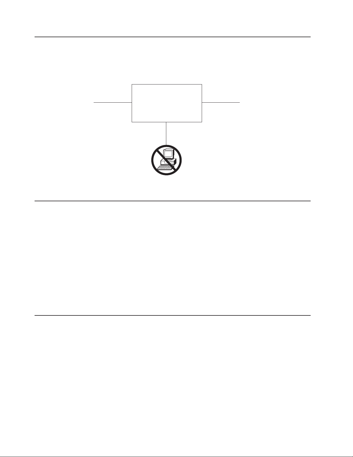
A headless appliance
The IP Storage 200i is a headless appliance; it does not come with a monitor or
keyboard. Do not attach a monitor or keyboard during installation or normal
operation.
Network Power
Setting up the appliance
To set up the IP Storage 200i:
1. If you are setting up a Model 210, install the engine in a rack (see “Installing a
Model 210 in a rack”).
2. Install any optional features (see “Installing optional features” on page 10).
3. Connect the power cords and network cables (see “Attaching the cables” on
page 26).
4. Start the appliance and verify that the power-on diagnostics completed
successfully (see “Powering on the appliance” on page 30).
5. Insert the Recovery CD in the CD-ROM drive. This CD might be required for
future system recovery and must be kept in the CD-ROM drive at all times.
6. Perform the initial configuration (see “Performing initial configuration” on
page 32).
IBM
IP Storage
Display and
keyboard
Installing a Model 210 in a rack
For Model 210, use the rack-mounting kit provided to install the engine in a rack.
Before you begin the installation:
v Review the documentation that comes with your rack enclosure.
v Ensure that the room air temperature is below 35°C (95°F).
v Maintain a 15-cm (6-in.) clearance around the engine for air circulation.
v Plan the installation working from the bottom of the rack up.
v Take precautions to prevent the rack from overloading the power outlets when
you install multiple components in the rack.
6 IBM TotalStorage IP Storage 200i Models 110 and 210 Installation Guide
Page 19
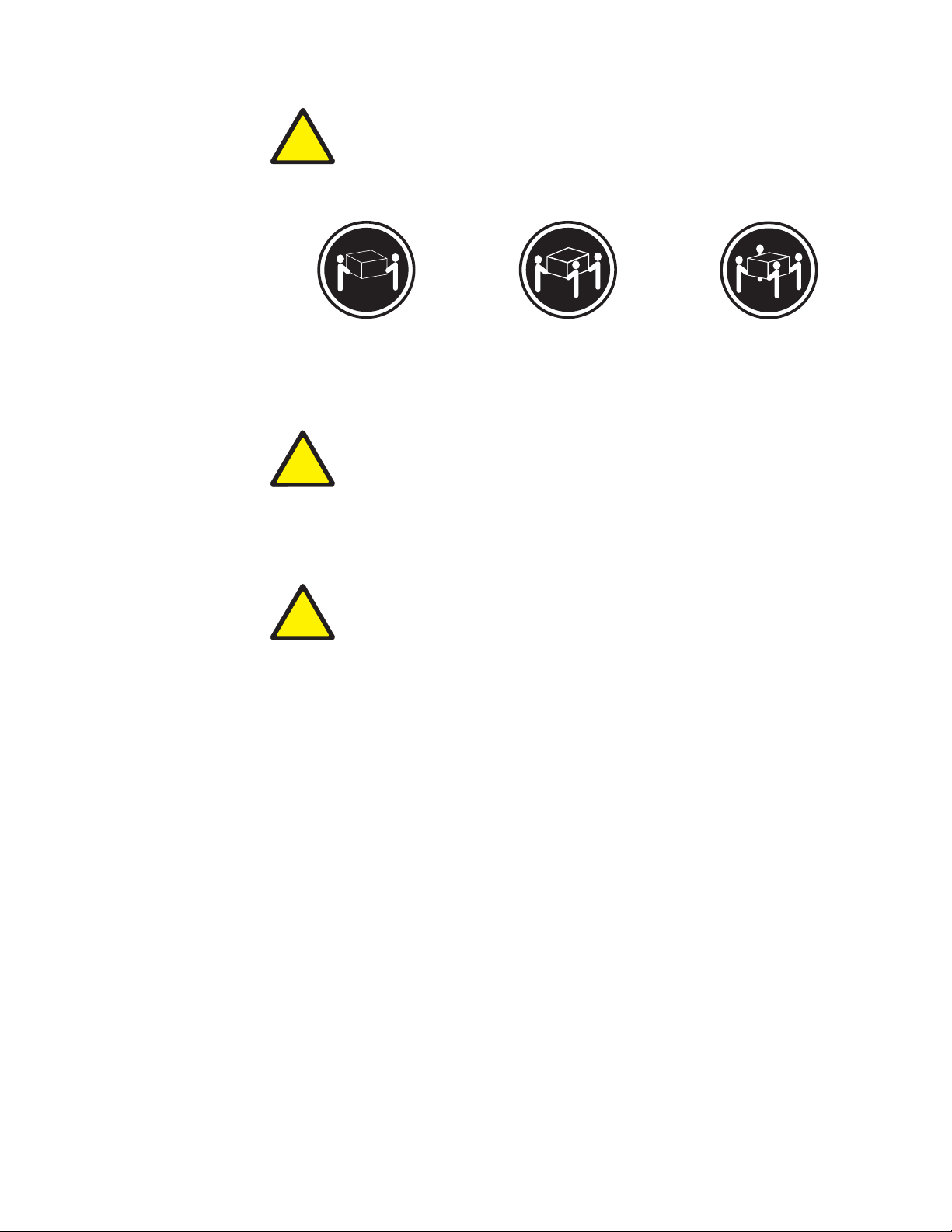
!
≥18 kg (37 lbs) ≥32 kg (70.5 lbs) ≥55 kg (121.2 lbs)
CAUTION:
<2–17> Use safe practices when lifting.
!
CAUTION:
<2–18> Do not place any object weighing more than 82 kg (180 lb) on top of
rack-mounted devices.
!
CAUTION:
<2-20> Do not place your fingers around the rack-support wheels when
lowering the engine onto the slide rails. Ensure that your fingers do not
become pinched between the wheels and the rail.
Note: For translations of this safety notice, refer to Safety Information, which can
be found on the Publications and Code CD that was shipped with your
appliance.
To install the Model 210 in a rack:
1. Review the safety precautions in “Safety precautions” on page ix.
2. Remove all hard disk drives before installing the engine in a rack to lighten the
weight of the engine:
a. Pull the drive tray handle to the open position (perpendicular to the hard
drive) to disengage the hard disk drive connector from the backplane at the
back of the drive bay.
b. Wait approximately 30 seconds to allow the hard disk drive to spin down.
c. Pull the hot-swap hard disk drive assembly from the drive bay.
3. Remove the rack doors and the side panels during the installation, if necessary.
Chapter 2. Installation procedures 7
Page 20
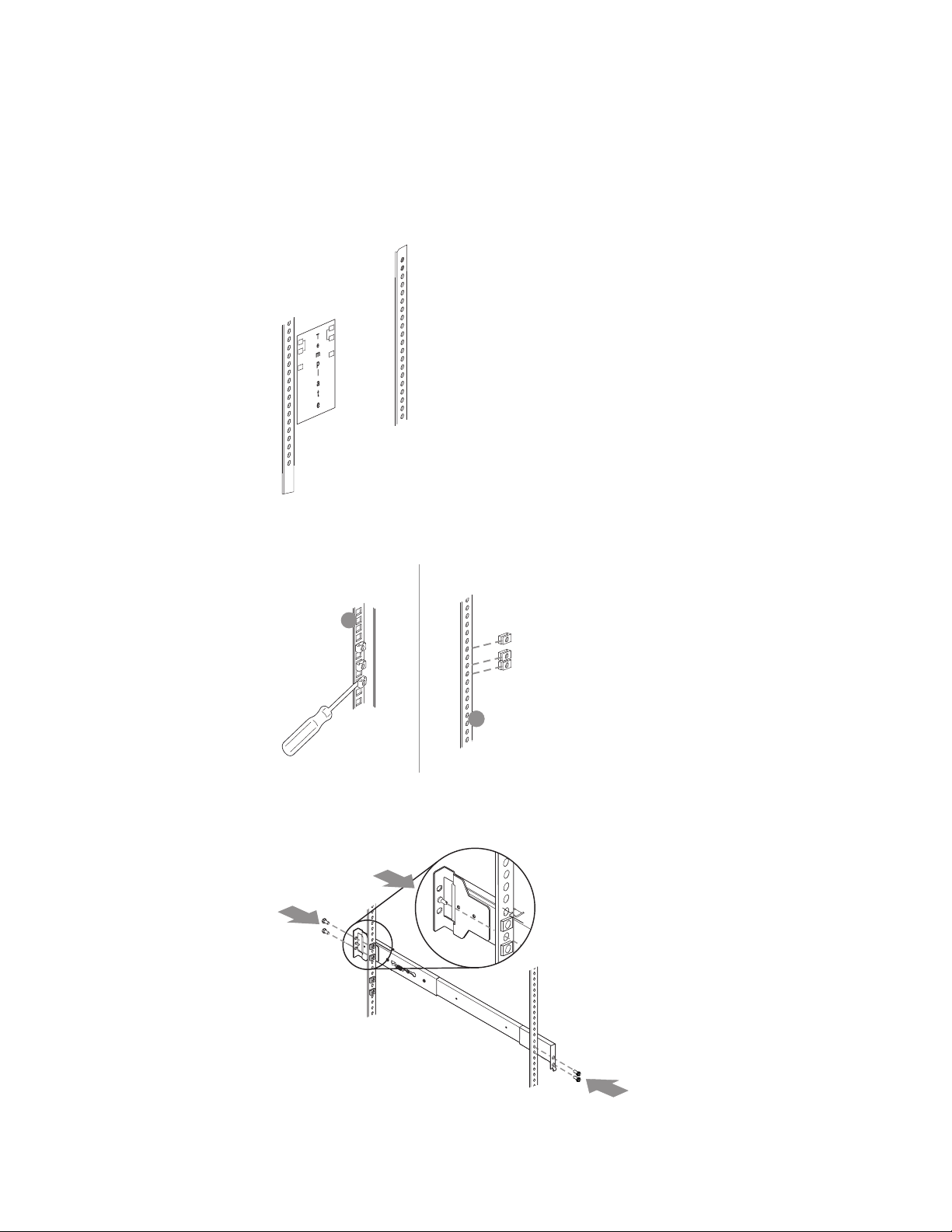
4. Using the stickers provided on the rack-mounting template, mark holes on the
front and rear of the rack in the locations indicated by the arrows. The stickers
indicate where to place the clip nuts or cage nuts in the next step.
Note: Position the template to the rack so that the edges of the template do
not overlap any other devices to be installed.
5. Insert the cage nuts using a screwdriver or the cage-nut-insertion tool or slide
on the clip nuts (as required for your rack) into all marked holes.
1
2
6. Use the pins on the slide rail to align the rail with the rack. Use the M6 screws
to secure the slide rail to the rack. Repeat this step for the other slide rail.
1
2
A
8 IBM TotalStorage IP Storage 200i Models 110 and 210 Installation Guide
2
Page 21
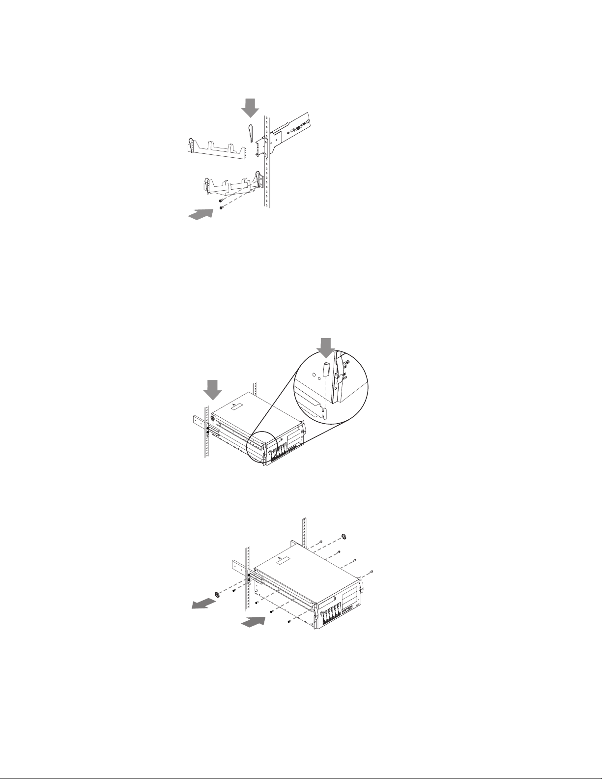
7. Use the M6 screws to attach the hinge bracket to the rear of the rack. Then,
use the hinge pin to attach the cable-management assembly to the slide rail.
2
1
8. Fully extend the slide rails out of the rack.
9. Lift the engine above the rails. Then, rest the rack-support wheels, located near
the rear of the engine, on the slide rails.
10. Lower the front of the engine onto the slide rails.
Note: Be sure that the bracket notches on the front of the engine fit securely
on the tabs located on the front of the slide rails.
2
A
1
B
C
11. Use the M4 screws to secure the engine to the rails. Unscrew the rear
rack-support wheels and store them in a safe place.
A
2
1
12. Replace the rack door and side panels, if necessary.
13. Replace the hard disk drives in the engine:
a. Ensure that the tray handle is open (that is, perpendicular to the hard disk
drive).
b. Align the rails on the hard disk drive assembly with the guide rails in the
drive bay.
Chapter 2. Installation procedures 9
Page 22
c. Gently push the hard disk drive assembly into the drive bay until the hard
disk drive connects to the backplane.
d. Push the tray handle toward the closed position until it locks the hard disk
drive in place.
Installing optional features
The section provides instructions for installing the optional features.
Connecting a storage unit to the Model 210
You can attach up to three Model EXP storage units to the Model 210.
For detailed installation and cabling instructions for the storage unit, refer to the IBM
TotalStorage IP Storage 200i Storage Unit Installation Guide.
To attach storage units to a Model 210:
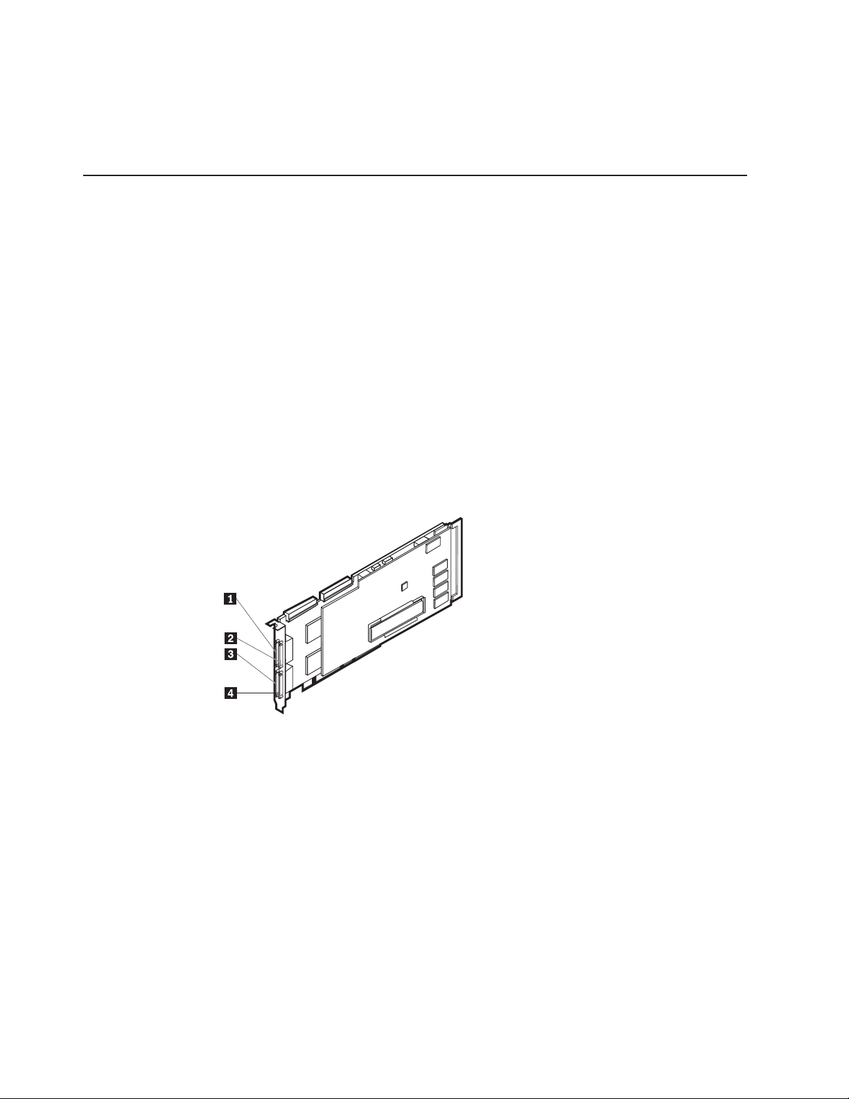
1. Connect one end of a 68-pin very-high density connector interface (VHDCI)
SCSI cable to the appropriate external channel connector on the ServeRAID-4H
adapter.
Important: Connect the first storage unit to Channel 2, the second to
Channel 3, and the third to Channel 4.
1 External channel 1
2 External channel 2
3 External channel 3
4 External channel 4
Figure 1. External channels of the ServeRAID-4H controller
2. Connect the other end of the SCSI cable to the storage unit.
10 IBM TotalStorage IP Storage 200i Models 110 and 210 Installation Guide
Page 23
Installing a hot-swap hard disk drive
Attention:
v To maintain correct system cooling, do not operate the appliance for more than 2
minutes without either a hard disk drive or a filler panel installed in each drive
bay. Therefore, if you are replacing a defective hot-swap drive, either leave the
defective drive in place or put in a filler panel until you have a replacement drive.
v When you handle electrostatic discharge-sensitive devices (ESDs), take
precautions to avoid damage from static electricity. For details about handling
these devices, refer to “Handling electrostatic discharge-sensitive devices” on
page 54.
v You cannot mix drives with different sizes in the Models 110 and 210. You can,
however, mix drives with different sizes in the storage unit Model EXP.
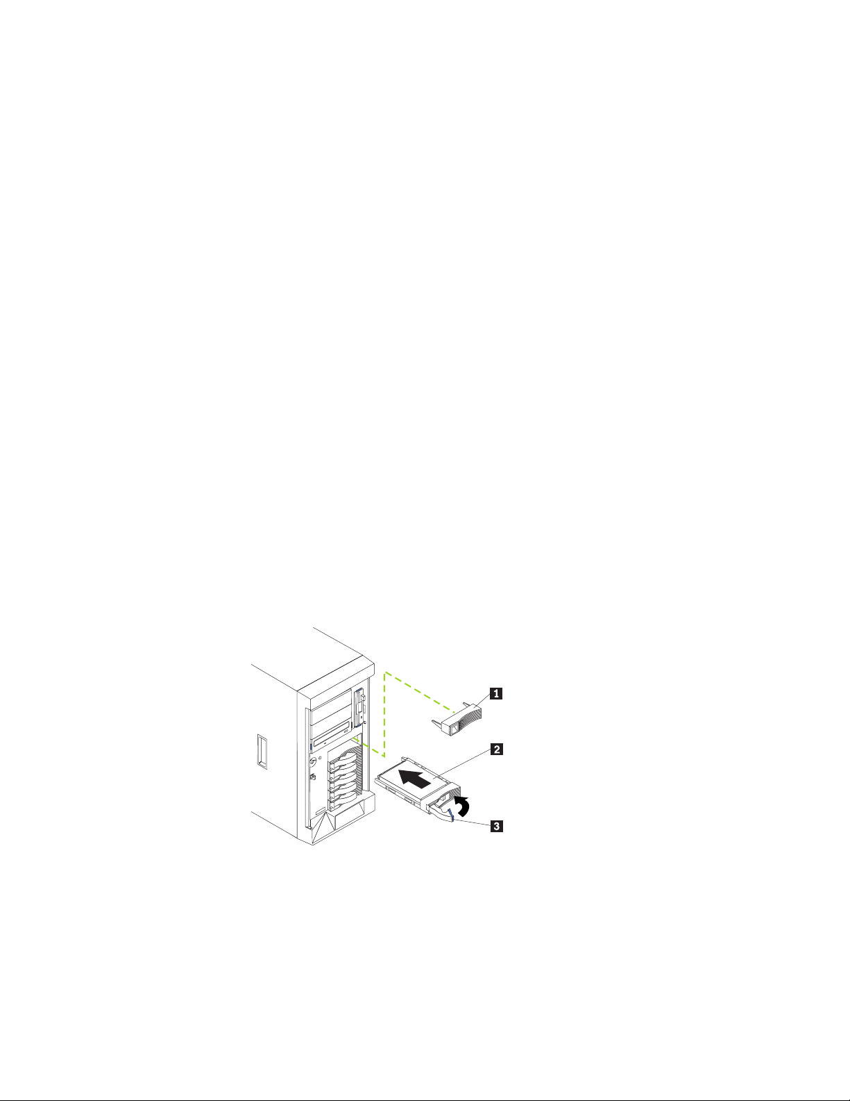
To install a hot-swap hard disk drive in a drive bay:
1. Remove the filler panel from one of the empty hot-swap drive bays by inserting
your finger in the depression on the left side of the filler panel and pulling it
away from the appliance.
2. Install the hot-swap hard disk drive in the drive bay:
a. Ensure that the tray handle is open (that is, perpendicular to the hard disk
drive).
b. Align the rails on the hard disk drive assembly with the guide rails in the
drive bay.
c. Gently push the hard disk drive assembly into the drive bay until it connects
to the backplane.
d. Push the tray handle toward the closed position until it locks the hard disk
drive in place.
1 Filler panel
2 Hard disk drive
3 Drive tray handle (in open position)
Figure 2. Installing a hard disk drive
Chapter 2. Installation procedures 11
Page 24

3. Check the hard disk drive status indicators to verify that the hard disk drives are
operating correctly. The Hard Disk Drive Status LED is immediately to the right
of the hard disk drive.
v When the green LED flashes rapidly (three flashes per second), the controller
is identifying the hard disk drive.
v When the green LED flashes slowly (one flash per second), the hard disk
drive is being rebuilt.
v When the amber LED is on continuously, the hard disk drive has failed.
Installing memory modules
Your appliance comes with two or more dual inline memory modules (DIMM)
installed on the system board in the DIMM connectors. You can install an additional
1 GB of memory in both models.
Notes:
1. Memory modules must be installed or replaced in matched pairs.
2. The Models 110 and 210 are shipped with two DIMMs installed in DIMM slots 1
and 4. These slots must be filled for correct operation. You can install additional
DIMMs as a matched pair in DIMM slots 2 and 3.
To install a memory module:
1. Prepare to install the memory module (see “Preparing to install a memory
module”).
2. Remove the cover (see “Removing the cover” on page 13).
3. Install the memory module (see “Installing and replacing a memory module” on
page 14).
4. Replace the cover (see “Replacing the cover” on page 17).
Preparing to install a memory module
Before installing a memory module:
v Become familiar with the safety and handling guidelines specified under
“Handling electrostatic discharge-sensitive devices” on page 54.
v The blue color on components and labels inside your Models 110 and 210
identifies touch points where a component can be gripped, a latch moved, and so
on. The only exception to this is the power supplies, which are orange.
v Make sure that you have an adequate number of correctly grounded electrical
outlets for the engines and any other options that you intend to install.
v Before you begin installing components, read the safety information found in
“Appendix C. Safety notices” on page 47.
Memory modules must be added, installed, or replaced two modules at a time.
System reliability considerations: To help ensure correct cooling and system
reliability, make sure that:
v Each of the drive bays has either a hard disk drive or a filler panel installed.
v You replace a removed hot-swap drive within 2 minutes of removal.
v The cover is in place during normal operations, or is removed for no longer than
30 minutes while the appliance is operating.
Note: The front door (Model 110) can be removed permanently without affecting
system reliability.
12 IBM TotalStorage IP Storage 200i Models 110 and 210 Installation Guide
Page 25
Removing the cover
This section describes how to remove the cover from Model 110 and Model 210.
Attention: For correct cooling and airflow, replace the cover before switching on
the appliance. Operating the appliance for extended periods of time (over 30
minutes) with the cover removed might damage appliance components.
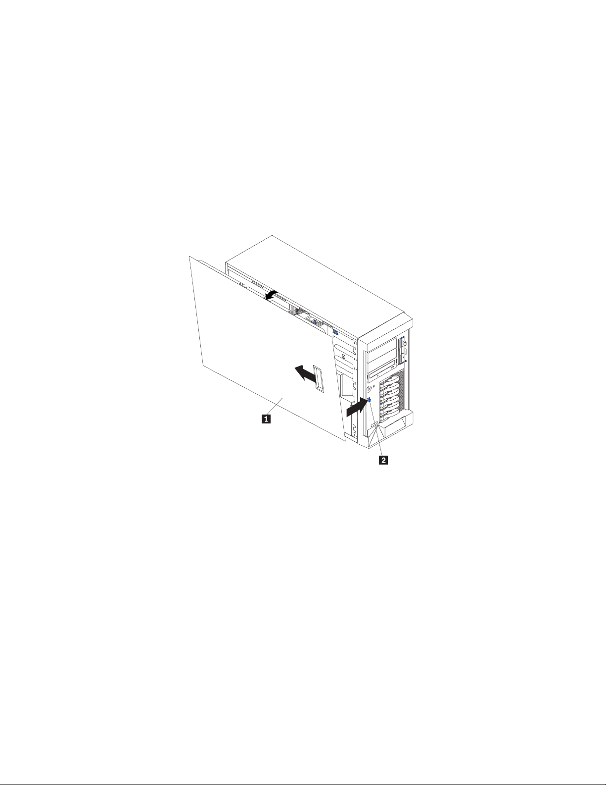
Removing the Model 110 cover: To remove the left-side cover of the Model 110:
1. Power OFF the appliance and all attached devices, and disconnect all external
cables and power cords.
2. Move the cover-release lever down while sliding the left-side cover toward the
rear of the appliance about 25 mm (1 in.).
3. Lift the cover off the appliance and set the cover aside.
1 Left-side cover
2 Cover release lever
Chapter 2. Installation procedures 13
Page 26
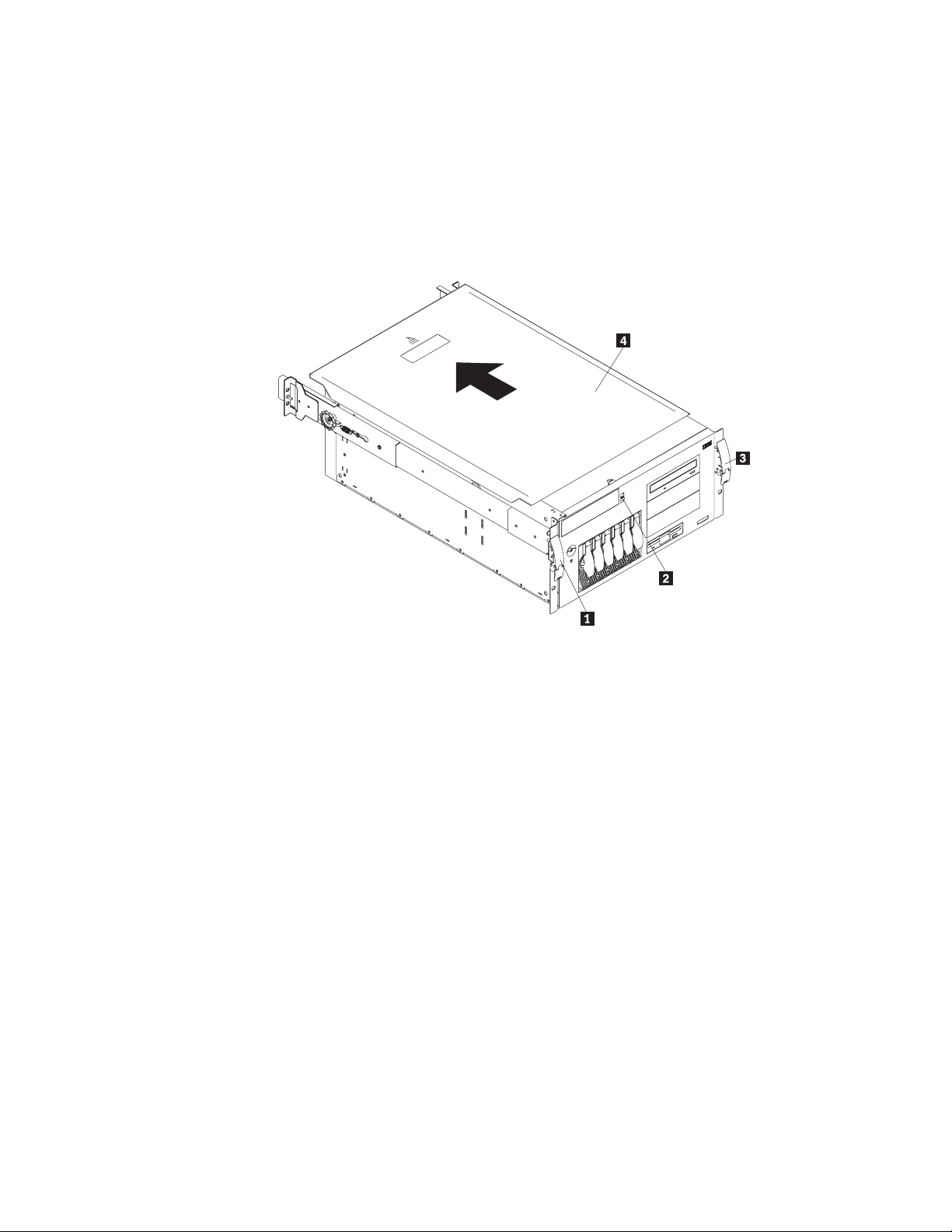
Removing the Model 210 cover: To remove the appliance top cover:
1. Power OFF the appliance and all attached devices and disconnect all external
cables and power cords.
2. Release the left and right safety latches and pull the appliance out of the rack
enclosure until both slide rails lock.
3. Move the cover-release lever down while sliding the top cover toward the rear of
the appliance about 25 mm (1 in.).
4. Lift the cover off the appliance and set the cover aside.
1 Left-side latch
2 Cover release lever
3 Right-side latch
4 Top cover
Installing and replacing a memory module
Model 110 and Model 210 support two additional 512-MB DIMMs. Model 110
support a maximum of 1.5 GB of memory. Model 210 support a maximum of 2 GB
of memory.
Attention: When you handle electrostatic discharge-sensitive devices (ESDs),
take precautions to avoid damage from static electricity. For details on handling
these devices, refer to “Handling electrostatic discharge-sensitive devices” on
page 54.
14 IBM TotalStorage IP Storage 200i Models 110 and 210 Installation Guide
Page 27
DANGER
<1–5> Electrical current from power, telephone and communication cables
is hazardous.
To avoid a shock hazard:
v Do not connect or disconnect any cables or perform installation,
maintenance, or reconfiguration of this product during an electrical
storm.
v Connect all power cords to a properly wired and grounded electrical
outlet.
v Connect to properly wired outlets any equipment that will be attached to
this product.
v When possible, use one hand only to connect or disconnect signal
cables.
v Never turn on any equipment when there is evidence of fire, water, or
structural damage.
v Disconnect the attached power cords, telecommunications systems,
networks, and modems before you open the device covers, unless
instructed otherwise in the installation and configuration procedures.
v Connect and disconnect cables as described in the following table when
installing, moving, or opening covers on this product or attached
devices.
To Connect To Disconnect
1. Turn everything OFF.
2. First, attach all cables to devices.
3. Attach signal cables to connectors.
4. Attach power cords to outlet.
5. Turn device ON.
1. Turn everything OFF.
2. First, remove power cords from outlet.
3. Remove signal cables from connectors.
4. Remove all cables from devices.
CAUTION:
<2–19> The power control button on the device and the power switch on the
power supply do not turn off the electrical current supplied to the device. The
device also might have more than one power cord. To remove all electrical
current from the device, ensure that all power cords are disconnected from
the power source.
Note: For translations of these safety notices, refer to Safety Information, which
can be found on the Model 210 that was shipped with your appliance.
Chapter 2. Installation procedures 15
Page 28
To install a memory module (DIMM):
1. Review the safety precautions listed in Statement 1 and Statement 5 in
“Appendix C. Safety notices” on page 47.
2. Review the documentation that comes with your DIMM.
3. Power OFF the appliance and peripheral devices, and disconnect all external
cables and power cords.
4. If you are replacing a DIMM, remove the defective DIMM by pulling it firmly out
of the connector.
5. Touch the static-protective package containing the DIMM to any unpainted
metal surface on the appliance, and remove the DIMM from the package. This
discharges any static electricity from the package and from your body.
6. Ensure that the DIMM retaining clips are in the open position.
Note: Handle the retaining clips gently to avoid breaking them or damaging
the DIMM connectors.
1 DIMM 1
2 DIMM 2
3 DIMM 3
4 DIMM 4
5 Retaining clip
Figure 3. Installing a DIMM
16 IBM TotalStorage IP Storage 200i Models 110 and 210 Installation Guide
Page 29
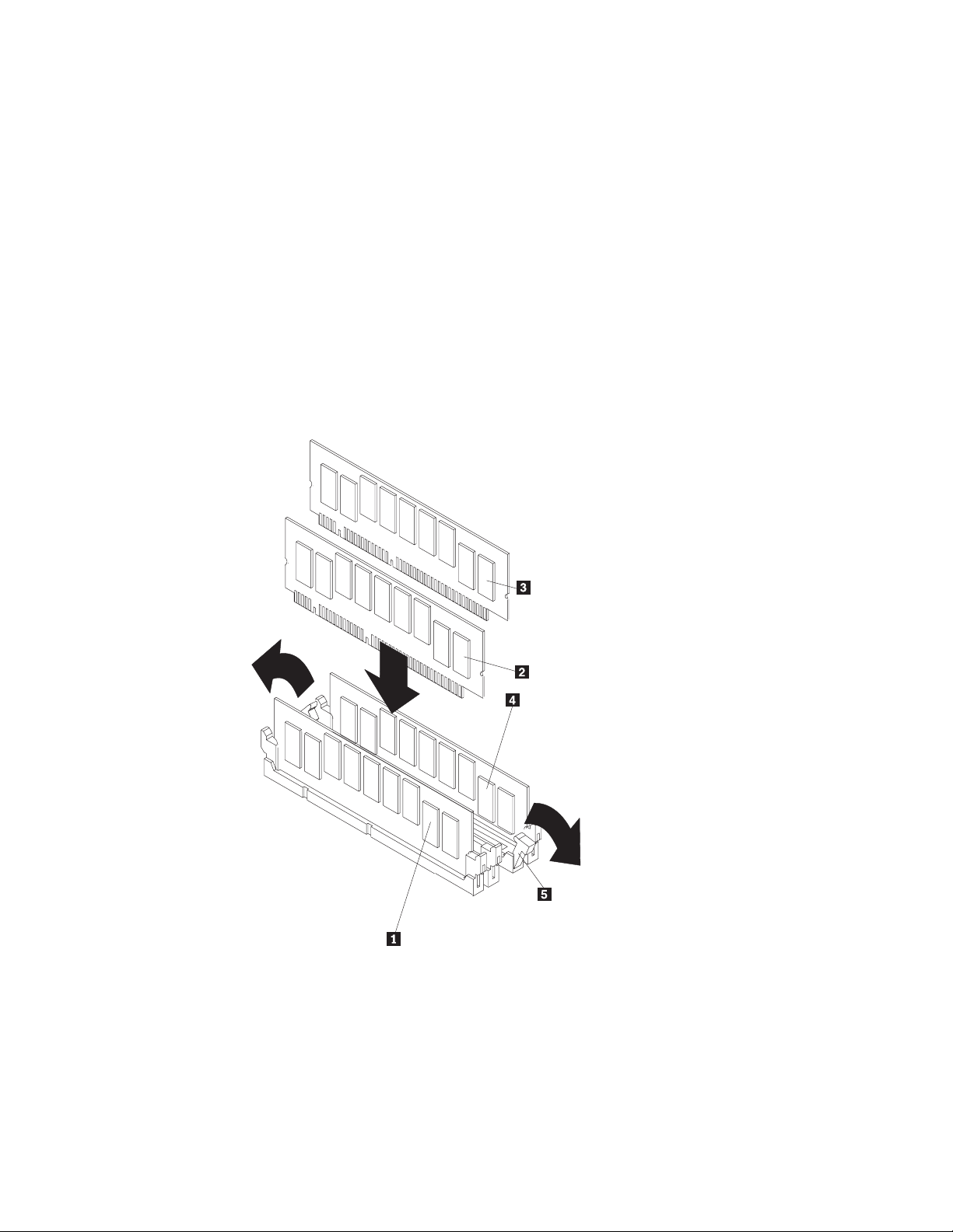
7. Turn the DIMM so that the pins align correctly with the connector. Note the
notches in the DIMM edge that key the DIMM to the connector.
8. Insert the DIMM into the connector by pressing on one end of the DIMM and
then on the other end of the DIMM. Be sure to press straight into the
connector. Be sure that the retaining clips snap into the closed position.
Note: DIMM slots 1 and 4 must be filled. You can place additional memory in
slots 2 and 3.
6
1 Memory module 1
2 Memory module 2
3 DIMM slot 1
4 DIMM slot 2
5 DIMM slot 3
6 DIMM slot 4
Figure 4. Installing a DIMM
9. Make sure that the retaining clips are in the closed position. If a gap exists
between the DIMM and the retaining clips, the DIMM has not been correctly
seated. In this case, open the retaining clips and remove the DIMM; then,
reinsert the DIMM.
10. Repeat steps 5 on page 16 through 9 for the remaining DIMM.
Replacing the cover
This section describes how to replace the cover on the Model 110 and Model 210.
Replacing the Model 110 cover: To replace the left-side cover:
1. Align the cover with the left side of the appliance, about 25 mm (1 in.) from the
front of the engine; place the bottom of the cover on the bottom rail of the
chassis.
2. Insert the tabs at the top of the cover into the slots at the top of the engine.
Chapter 2. Installation procedures 17
Page 30

3. Hold the cover against the engine and slide the cover toward the front of the
engine until the cover clicks into place.
1 Slots
2 Left-side cover
Replacing the Model 210 cover: To replace the top cover:
1. Align the top cover with the top of the engine, about 25 mm (1 in.) from the front
of the appliance; the flanges on the left and right sides of the cover should be
on the outside of the engine chassis.
2. Hold the cover against the engine and slide the cover toward the front of the
engine until the cover clicks into place.
1 Flange
2 Top cover
3 Side latches
18 IBM TotalStorage IP Storage 200i Models 110 and 210 Installation Guide
Page 31

Setting memory configuration
You are not required to attach a monitor or keyboard to the appliance to set the
memory configuration.
Replacing the Gigabit Ethernet adapter
Your appliance comes with a Gigabit Ethernet adapter in PCI slot 4. The Gigabit
Ethernet adapter can be either a Gigabit Ethernet Copper Adapter or a Gigabit
Ethernet SX Adapter, depending on your needs. Use these instructions to replace a
defective Gigabit Ethernet Adapter or to change your adapter type (for example,
changing from a Gigabit Ethernet Copper Adapter to a Gigabit Ethernet SX
Adapter).
Replacing the Gigabit Ethernet adapter
To replace the Gigabit Ethernet adapter:
1. Power OFF the appliance, and remove the power cords and external cables.
2. Remove the engine cover (see “Removing the cover” on page 13).
3. Remove the defective Gigabit Ethernet adapter:
1 Blue adapter-retention bracket
2 Expansion slot cover
3 Adapter
4 Adapter support bracket retaining clip
5 Adapter support bracket
Figure 5. Replacing the Gigabit Ethernet adapter
a. Remove the blue adapter-retention bracket by pressing down on the tab
and lifting up the bracket.
b. Remove the adapter support bracket by pressing down on both tabs and
lifting up the bracket.
c. Carefully lift out the Gigabit Ethernet adapter.
4. Touch the static-protective package containing the Gigabit Ethernet adapter to
an unpainted metal expansion-slot cover on the engine. This discharges any
static electricity from the package and from your body.
Chapter 2. Installation procedures 19
Page 32

5. Remove the adapter from the static-protective package holding the controller
by the edges. Do not touch any exposed components or gold-edge
connections on the controller.
6. Carefully grasp the adapter by its top edge or upper corners and align it with
the expansion slot on the system board.
7. Press the adapter firmly into the expansion slot.
Attention: When you install an adapter in the engine, be sure that it is
completely and correctly seated in the system-board connector before you
apply power. Incomplete insertion might cause damage to the system board or
the adapter.
8. Align the bottom tabs of the adapter-retention bracket with the holes at the top
of the expansion slots, and press the adapter-retention bracket toward the
back of the engine until it clicks into the locked position.
9. Align the bottom tabs of the adapter-support bracket with the holes on the side
of the fan assembly, and press the adapter-support bracket toward the front of
the engine until it clicks into the locked position.
10. Replace the cover (see “Replacing the cover” on page 17) and plug in the
power cords and network cables (see “Attaching network cables”).
11. Power ON the appliance. The PCI BIOS automatically assigns resources to the
adapter.
Attaching network cables
This section describes how to attach the network cable to a Gigabit Ethernet
Copper Adapter or Gigabit Ethernet SX Adapter.
Gigabit Ethernet Copper Adapter: Insert the Category 5 twisted-pair RJ-45
network cable into the adapter’s connector.
LINK
ACT
0
0
0
/
0
10
/
10
X
T
Figure 6. Attaching a Gigabit Ethernet Copper Adapter
20 IBM TotalStorage IP Storage 200i Models 110 and 210 Installation Guide
Page 33

For 1000BASE-T or 100BASE-TX, your network cable must be Category 5,
twisted-pair cabling. If you plan to run the adapter at 1000 Mbps, it must be
connected to a compatible 1000-Mbps switch.
For 10BASE-T, use Category 3, 4, or 5 twisted-pair cabling. If you want to use this
adapter in a residential environment, you must use a Category 5 cable.
Gigabit Ethernet SX Adapter: Remove and save the fiber-optic connection cover.
Insert a 1000BASE-SX duplex type SC fiber optic connector into the ports on the
Gigabit adapter bracket, as shown in the following illustration. The connector and
ports are keyed for correct orientation.
The fiber-based adapter must be connected to an IEEE 802.3z-compliant gigabit
switch, such as the Intel
TX
RX
LINK
®
470 Gigabit Switch.
1 Transmit port
2 Receive port
Figure 7. Attaching a Gigabit Ethernet SX Adapter
Chapter 2. Installation procedures 21
Page 34

Replacing the battery
IBM has designed this product with your safety in mind. The lithium battery must be
handled correctly to avoid possible danger. If you replace the battery, you must
adhere to the following safety guidelines.
!
CAUTION:
<2–16> When replacing the lithium battery, use only IBM Part Number
33F8354 or an equivalent type battery recommended by the manufacturer. If
your system has a module containing a lithium battery, replace it only with
the same module type made by the same manufacturer. The battery contains
lithium and can explode if not correctly used, handled, or disposed of.
Do not:
v Throw or immerse into water
v Heat to more than 100°C (212°F)
v Repair or disassemble
Dispose of the battery as required by local ordinances or regulations.
Note: For translations of this safety notice, refer to Safety Information, which can
be found on the support support Publications and Code CD that was shipped
with your appliance.
Note: In the U.S., call 1 800 BM-4333 for information about battery disposal.
If you replace the original lithium battery with a heavy-metal battery or a battery with
heavy-metal components, be aware of the following environmental consideration.
Batteries and accumulators that contain heavy metals must not be disposed of with
normal domestic waste. They will be taken back free of charge by the manufacturer,
distributor, or representative, to be recycled or disposed of in a correct manner. To
order replacement batteries, call 1 800 772-2227 within the United States.
Before you begin:
v Review the safety precautions listed in “Appendix C. Safety notices” on page 47.
v Follow any special handling and installation instructions supplied with the
replacement battery.
Note: After you replace the battery, you must reconfigure your appliance and reset
the system date and time.
22 IBM TotalStorage IP Storage 200i Models 110 and 210 Installation Guide
Page 35

To replace the battery:
1. Power OFF the appliance and peripheral devices, and disconnect all external
cables and power cords.
2. Remove the appliance cover.
3. Remove all of the adapters:
1 Blue adapter-retention bracket
2 Expansion slot cover
3 Adapter
4 Adapter support bracket retaining clip
5 Adapter support bracket
Figure 8. Removing adapters
a. Remove the blue adapter-retention bracket by pressing down on the tab and
lifting up the bracket.
b. Remove the adapter support bracket by pressing down on both tabs and
lifting up the bracket.
c. Carefully lift out the adapters.
Attention: Note the location of the adapters. You must replace each adapter
in the same slot from which it was removed.
Note: You do not need to unplug the internal adapter cables.
Chapter 2. Installation procedures 23
Page 36

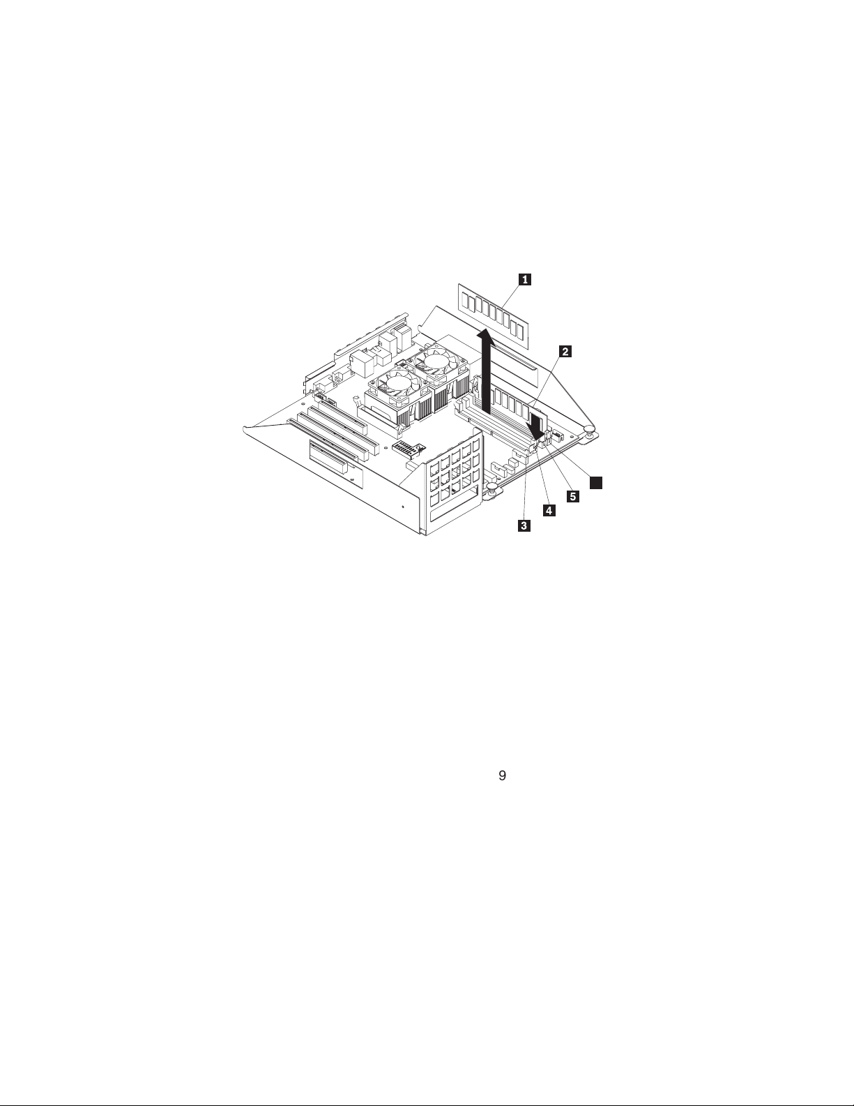
4. Remove the battery:
1 Battery
Figure 9. Replacing the battery
a. Use one finger to lift the battery clip over the battery.
b. Use another finger to slightly slide the battery out from its socket. The spring
mechanism will push the battery out toward you as you slide it from the
socket.
c. Use your thumb and index finger to pull the battery from under the battery
clip.
d. Ensure that the battery clip is touching the base of the battery socket by
pressing gently on the clip.
24 IBM TotalStorage IP Storage 200i Models 110 and 210 Installation Guide
Page 37

5. Insert the new battery:
Note: Ensure that the polarity of the battery is correct. The positive (+) side
must face up.
a. Tilt the battery so that you can insert it into the socket, under the battery
clip.
b. As you slide it under the battery clip, press the battery down into the socket.
6. Replace the adapters:
a. Carefully grasp the adapter by its top edge, align it with the expansion slot
on the system board, and press it firmly into the expansion slot.
Figure 10. Inserting an adapter into the PCI expansion slot
Attention: When you install an adapter in the engine, be sure that it is
completely and correctly seated in the system-board connector before you
apply power. Incomplete insertion might cause damage to the system board
or the adapter.
b. Align the bottom tabs of the adapter-retention bracket with the holes at the
top of the expansion slots, and press the adapter-retention bracket toward
the back of the engine until it clicks into the locked position.
c. Align the bottom tabs of the adapter-support bracket with the holes on the
side of the fan assembly, and press the adapter-support bracket toward the
front of the engine until it clicks into the locked position.
7. Reinstall the engine cover, and connect the power cords and external cables.
Note: Wait approximately 20 seconds after you plug the power cords of your
appliance into electrical outlets for the Power button to become active.
8. Power ON the appliance.
9. Start the Configuration/Setup Utility program and set configuration parameters:
v Set the system date and time
v Set the power-on password
v Reconfigure your appliance
Chapter 2. Installation procedures 25
Page 38

Installing the Tower-to-Rack Kit
Refer to the instructions that come with your Tower-to-Rack Kit for information on
converting a tower model to a rack-mountable model.
Attaching the cables
This section describes how to attach the power and network cables to your
appliance.
Model 110
To attach the cables:
1. For each of the three power cords, connect the appropriate end of the power
cord to a power supply and the opposite end to a properly wired and grounded
electrical outlet.
2. Connect one end of the Gigabit Ethernet cable to the Gigabit Ethernet adapter
located in expansion slot 4, and connect the opposite end to the system
network.
Note: You may use a 10/100 Ethernet cable if your network does not support
Gigabit Ethernet.
123
1
2
3. Route the power and network cables through the cable-restraint bracket on the
rear of the engine by opening the bracket and threading the cables through the
slots in interior of the bracket, and close the bracket.
26 IBM TotalStorage IP Storage 200i Models 110 and 210 Installation Guide
Page 39

Model 210
To attach the cables:
1. Press the safety latches and slide the engine halfway into the rack.
2. For each of the three power cords, connect one end of the power cord to a
power supply and the opposite end to a properly wired and grounded electrical
outlet.
3. Connect one end of the Gigabit Ethernet cable to the Gigabit Ethernet adapter
located in expansion slot 4, and connect the opposite end to the system
network.
Note: You may use a 10/100 Ethernet cable if your network does not support
Gigabit Ethernet.
4. Route the power and network cables through the cable-restraint bracket on the
rear of the engine by opening the bracket and threading the cables through the
slots in the interior of the bracket, and close the bracket.
5. Slide the engine into the rack until the safety latches snap shut.
6. Route the cables through the cable-management assembly on the rack.
Chapter 2. Installation procedures 27
Page 40

7. Use the cable straps or cable ties to secure the cables to the
cable-management assembly.
8. Insert the M6 screws through the release-latch bracket assembly.
Note: If you are moving the rack or if the rack is in a vibration-prone area,
inserting the M6 screw is required; otherwise, this step is optional.
Connecting external options
This section shows you the location of the parts to which you can connect any
external devices.
Before attaching an external device, read the documentation that comes with your
options. Use the information in this section to understand the input/output ports on
the appliance.
The IP Storage 200i is a headless appliance. Do not attach a keyboard or monitor
to the appliance during installation or normal operation.
28 IBM TotalStorage IP Storage 200i Models 110 and 210 Installation Guide
Page 41

Input/output connector locations
Figure 11 shows the input/output connectors (ports) and LEDs on the rear of the
engine.
6
7
8
1 DC power LED
2 AC power LED
3 Serial port A
4 Mouse port
5 Keyboard port
6 Ethernet port
7 ISM ports
8 USB ports
9 Serial port C
10 Video port
Figure 11. Input and output connector ports
Input/output ports
This section provides information about the input/output (I/O) ports supported for
your appliance.
Serial ports
Each appliance has two standard serial ports: Serial port A and Serial port B. The
operating system can use and share both serial ports; however, the integrated
Service Console can use only Serial port A.
Video port
Each appliance has an integrated super video graphics array (SVGA) video
controller to which you can attach a monitor. A monitor is not required during
installation or normal operation.
Keyboard port
There is one keyboard port on the rear of your appliance. The keyboard port is not
used during installation or normal operation.
Chapter 2. Installation procedures 29
Page 42

Service Ethernet port
Your appliance has an integrated 10/100 Ethernet controller. This controller provides
an interface for connecting to 10-Mbps or 100-Mbps networks and provides
full-duplex (FDX) capability, which enables simultaneous transmission and reception
of data on the Ethernet local area network (LAN).
Note: The 100BASE-TX Fast Ethernet standard requires that the cabling in the
network be Category 5 or higher.
Configuring the Service Ethernet controller: When you connect your appliance
to the network, the Service Ethernet controller automatically detects the
data-transfer rate (10 Mbps or 100 Mbps) on the network and then sets the Service
Ethernet controller to operate at the appropriate rate. That is, the Ethernet controller
will adjust to the network data rate, whether the data rate is standard Ethernet
(10BASE-T), Fast Ethernet (100BASE-TX), half-duplex (HDX), or full-duplex (FDX).
The controller supports HDX and FDX modes at both speeds.
The Service Ethernet controller is a PCI Plug and Play device. You do not need to
set any jumpers or configure the controller for your operating system before you
use the Service Ethernet controller.
Failover for redundant Ethernet: The Serivice Ethernet adapter does not support
a failover function.
Powering on and off the appliance
This section describes steps for powering on and off the appliance.
Powering on the appliance
To power on the appliance:
1. Wait at least 20 seconds after connecting the power cords.
2. Press the power button on the front of the engine to power on the appliance.
Attention: The first time you start the appliance, a series of configuration and
system preparation programs run automatically. These programs must finish
running before you use any included applications to connect to or configure your
appliance. Wait at least 5 minutes before connecting to or configuring the
appliance after the initial system start.
30 IBM TotalStorage IP Storage 200i Models 110 and 210 Installation Guide
Page 43

3. Check that the Power-on LED is on and the Information LED and System Error
LED are both off.
Note: Depending on the system status, other LEDs may be on.
34
OK
TX
LINK
100
OK
MB
RX
1 Information LED
2 System Error LED
3 Power-on LED
4 POST Complete (OK) LED
Note: This LED is not enabled on the appliance. For system status,
observe the Information LED and System Error LED. These
LEDs are both off when no problems are detected during startup.
If a problem is detected during the diagnostics, refer to the IBM TotalStorage IP
Storage 200i Administrator’s Guide.
Powering off the appliance
CAUTION:
<2–19> The power control button on the device and the power switch on the
power supply do not turn off the electrical current supplied to the device. The
device also might have more than one power cord. To remove all electrical
current from the device, ensure that all power cords are disconnected from
the power source.
Note: For translations of this safety notice, refer to Safety Information, which can
be found on the Publications and Code CD that was shipped with your
appliance.
Attention: Powering off the appliance using the power button can result in a loss
of data. Instead, it is recommended you use the Administrative Console to shut
down. Refer to the IBM TotalStorage IP Storage 200i Administrator’s Guide for
instructions.
To power off the appliance:
1. Review the safety precautions in “Safety precautions” on page ix.
2. Press and hold the power button for 4 seconds to causes an immediate
shutdown of the appliance and place the appliance in standby mode.
3. Disconnect the appliance power cords from the electrical outlets.
Chapter 2. Installation procedures 31
Page 44

Note: Wait approximately 15 seconds after disconnecting the power cords for
your appliance to stop running. Watch for the Power-on LED on the
operator information panel to stop blinking.
Performing initial configuration
Before the IP Storage 200i can be fully functional as an iSCSI server, you must
complete a set of required configuration tasks from the Web-based
appliance-management utility, called the Administrative Console. Because the
appliance is headless, configuration must be completed from another machine in
the same network, known as the management workstation.
This section steps you through the following procedures to perform the minimum
required configuration. Refer to the IBM TotalStorage IP Storage 200i
Administrator’s Guide for information about configuring your storage settings.
1. Accessing the Administrative Console
2. Logging in to the Administrative Console
3. Taking control of the Administrative Console
4. Configuring the network
5. Creating a logical drive
6. Creating and assigning VLUNs
Note: After you complete the required configuration tasks, it is important to back up
your configuration. See the IBM TotalStorage IP Storage 200i Administrator’s
Guide for instructions on backing up your configuration files.
Prerequisites
The IP Storage 200i requires a Web browser to access the Administrative Console.
The supported Web browsers are Microsoft Internet Explorer 5.0 (and later) and
Netscape 4.5 (and later) running on Windows 98, Windows Millennium, Windows
NT, or Windows 2000. An Internet connection is recommended.
Note: The IP Storage 200i requires a direct connection to the Internet from the
browser, not through a proxy server. If a proxy server is used for the Internet,
the IP Storage 200i must be excluded.
The Administrative Console requires the following plug-ins, which are available
online at java.sun.com:
™
v Java
v Sun Java Plug-in 1.3 or later
Note: The Sun Java Plug-in 1.3 is a product of Sun Microsystems, Inc. IBM does
Configuration files are backed up and recovered from a local FTP server. This FTP
server must support anonymous FTP. You can also update the system image from
this FTP server.
Swing 2
not distribute, support or maintain the Sun Java Plug-in 1.3, and your use of
this product is subject to license terms and conditions imposed by Sun
Microsystems, Inc. Contact Sun Microsystems, Inc. directly if you have any
questions about this product.
32 IBM TotalStorage IP Storage 200i Models 110 and 210 Installation Guide
Page 45

Accessing the Administrative Console
You can access the Administrative Console from the management workstation
through the Gigabit Ethernet (data port) or Service Ethernet (service port) . The
data port is the primary port used for storage traffic and configuration purposes. The
service port is used only for service purposes. No storage traffic occurs over the
service port.
Note: It is recommended that you use the service port for initally configuring the IP
Storage 200i.
Accessing the Administrative Console through the Service Ethernet
The Service Ethernet is preconfigured with IP address 192.9.200.1. The
Administrative Console must be configured on the 192.9.200 subnet to use the
preconfigured IP address.
Client Client
LAN
(same subnet)
100-Mb
switch
Administrative
Console
Windows NT , Windows 98,
Millenium, and 2000
Internet Explorer or Netscape
(direct connection, not proxy)
Java Plug-in 1.3 (see java.sun.com)
http://192.9.200.1:1959/IBM200i
®®
IBM
IP Storage
Service
port
Note:
Gigabit port
different subnets.
Gigabit
port
The Service port and
must be on
LAN
Gigabit
switch
Note: It is recommended that you use the default IP address of the Service
Ethernet; however, you can change the default IP address from the serial
console by typing enet and pressing Enter at the svc> prompt, and following
the instructions on the screen. (See the IBM TotalStorage IP Storage 200i
Administrator’s Guide for instructions on setting up the serial console.)
To access the Administrative Console through the Service Ethernet
1. Launch a Web browser from the management workstation.
2. Point the browser to the following address. Note that this address is
case-sensitive.
http://192.9.200.1:1959/IBM200i
When the workstation connects successfully to the appliance, a pop-up window
appears for login and password. Proceed to “Logging in to the Administrative
Console” on page 35.
Chapter 2. Installation procedures 33
Page 46

Accessing the Administrative Console through the Gigabit Ethernet
The Gigabit Ethernet is not preconfigured with an IP address.
Client
LAN
(same subnet)
Administrative
console
Windows 98, WindowsNT, Millenium, 2000
Internet Explorer or Netscape (direct connection, not proxy)
Java Plug-in 1.3 (see java.sun.com)
http://xxx.xxxx.xxx.xxx:3939/IBM200i
Client
Gigabit
switch
Client
Gigabit
Client
IBM
IP storage
To access the Administrative Console through the Gigabit Ethernet:
1. Launch a Web browser from the management workstation.
2. Point the Web browser to the appliance you are configuring using the following
address. Note that the address is case-sensitive.
http://IP_address:3939/IBM200i
where IP_address is the unique IP address you want to assign to the appliance.
This address must not be used by other systems in the network. For example:
http://128.1.3.1:3939/IBM200i
When the workstation connects successfully to the appliance, a pop-up window
appears for login and password. Proceed to “Logging in to the Administrative
Console” on page 35.
If the browser times out, the IP-address assignment was not successful. Go to a
command line on the management workstation. Type arp -a [n] (where n is a
user-defined IP address) and press Enter. If the corresponding MAC address does
not match the appliance’s MAC address, then the IP address is used by another
host; repeat this procedure using another IP address. If the ARP entry is resolved to
the correct appliance, delete the resolved entry by typing arp -d IP_address and
pressing Enter, and repeat this procedure. If you are setting up multiple appliances
simultaneously, retry with a different address after deleting the resolved entry.
Note: After you configure the IP address, use port number 1959 to access the
Administrative Console. For example:
http://128.1.3.1:1959/IBM200i
34 IBM TotalStorage IP Storage 200i Models 110 and 210 Installation Guide
Page 47

Logging in to the Administrative Console
To log in to the Administrative Console, use the following user name and password.
Note that these fields are case-sensitive.
User name administrator
Password password
Taking control of the Administrative Console
To make changes to the configuration, you must take control of the locks each time
you open the browser. Locks provide a way for multiple administrators to manage
the IP Storage 200i. After one administrator takes control of the lock, others see the
system only in read-only (browse) mode and are unable to make changes.
To take control of the Administrative Console and lock out all other administrators:
1. Click Network — Control locks.
2. Click Take control to change to edit mode.
Configuring the network
To configure the network:
1. Click Network — Data port. Select the port and click Edit. Set the IP address,
network mask, and host name. Then, click Apply.
2. Click Network — Settings. Set the domain name server address, domain, and
gateway address. Then, click Apply.
See the IBM TotalStorage IP Storage 200i Administrator’s Guide for detailed
instructions on configuring the network.
Creating a logical drive
A logical drive is a unit of storage that is made available to the network. It consists
of multiple physical disks combined using RAID 0, 1, 1E, 5, or 5E technology. A
physical disk cannot hold any user data until it belongs to a logical drive.
To create a logical drive:
1. Click Storage — RAID.
2. Highlight and right-click the controller. Then, click Add logical drive.
3. Select the RAID level, and write-cache method. Then, select the physical disks
from the Available disk list, and click >>> to move it to the Selected disks list.
4. Click Add.
See the IBM TotalStorage IP Storage 200i Administrator’s Guide for detailed
instructions on adding logical drives.
Chapter 2. Installation procedures 35
Page 48

Creating and assigning VLUNs
The IP Storage 200i is partitioned into virtual disks, known as virtual logical units
(VLUNs), that can be assigned to iSCSI client. The iSCSI client code installed on
the client machines allows iSCSI clients to access the VLUNs as directly-attached
devices.
To create and assign VLUNs:
1. Click Storage — iSCSI clients.
2. Select a logical drive, and then click Add VLUN.
3. Specify the size and number of the VLUNs, and then click Add.
4. Click a VLUN, and then click Assign Client.
5. Specify an iSCSI client name and password, and use the default iLUN. Then,
click Add.
6. Click Apply.
See the IBM TotalStorage IP Storage 200i Administrator’s Guide for detailed
instructions on creating and assigning virtual disks.
Configuring the system
To configure the system settings:
1. Click System — Date and time, and set the date and time on the appliance.
Then, click Apply.
2. Click System — Reset, and then click Reboot to reboot the appliance and
activate the configuration changes.
This completes the minimum required configuration procedures. See the IBM
TotalStorage IP Storage 200i Administrator’s Guide for more information about
configuring the appliance.
Note: You must reboot the appliance for changes to the data port, service port and
iSCSI targets to take affect; however, you can complete all your configuration
changes before rebooting.
36 IBM TotalStorage IP Storage 200i Models 110 and 210 Installation Guide
Page 49

Appendix A. Getting help, service, and information
If you need help, service, technical assistance, or just want more information about
IBM products, you will find a wide variety of sources available from IBM to assist
you.
IBM maintains pages on the World Wide Web where you can get information about
IBM products and services and find the latest technical information.
Table 4 lists some of these pages.
Table 4. IBM Web sites for help, services, and information
www.ibm.com Main IBM home page
www.storage.ibm.com IBM Storage home page
www.storage.ibm.com/support IBM NAS Support home page
Services available and telephone numbers listed are subject to change without
notice.
Service support
With the original purchase of an IBM hardware product, you have access to
extensive support coverage. During the IBM hardware product warranty period, you
may call the IBM Support Center (1 800 426-7378 in the U.S.) for hardware product
assistance covered under the terms of the IBM hardware warranty. See “Getting
help by telephone” on page 38 for Support Center telephone numbers in other
countries.
The following services are available during the warranty period:
v Problem determination: Trained personnel are available to assist you with
determining if you have a hardware problem and deciding what action is
necessary to fix the problem.
v IBM hardware repair: If the problem is determined to be caused by IBM hardware
under warranty, trained service personnel are available to provide the applicable
level of service.
v Engineering change management: Occasionally, there might be changes that are
required after a product has been sold. IBM or your reseller, if authorized by IBM,
will make Engineering Changes (ECs) available that apply to your hardware.
Be sure to retain your proof of purchase to obtain warranty service.
Please have the following information ready when you call:
v Machine type and model
v Serial numbers of your IBM hardware products
v Description of the problem
v Exact wording of any error messages
v Hardware and software configuration information
If possible, be at your computer when you call.
© Copyright IBM Corp. 2001 37
Page 50

A compatible monitor, keyboard, and mouse are required for many service activities.
Before you have the computer serviced, be sure to have these components
attached to your computer, either directly or through a console switch.
The following items are not covered:
v Replacement or use of non-IBM parts or nonwarranted IBM parts
Note: All warranted parts contain a 7-character identification in the format IBM
FRU XXXXXXX.
v Identification of software problem sources
v Configuration of BIOS as part of an installation or upgrade
v Changes, modifications, or upgrades to device drivers
v Installation and maintenance of network operating systems (NOSs)
v Installation and maintenance of application programs
Refer to your IBM hardware warranty for a full explanation of IBM’s warranty terms.
Before you call for service
Many computer problems can be solved without outside assistance, by using the
online help, by looking in the online or printed documentation that comes with your
network-attached storage appliance, or by consulting the support Web page noted
in Table 4 on page 37. Also, be sure to read the information in any README files
that come with your software.
Your network-attached storage appliance comes with documentation that contains
troubleshooting procedures and explanations of error messages. The
documentation that comes with your appliance also contains information about the
diagnostic tests you can perform.
If you receive a POST error code or beep code when you turn on your Network
Attached Server appliance, refer to the POST error-message charts in your
hardware documentation. If you do not receive a POST error code or beep code,
but suspect a hardware problem, refer to the troubleshooting information in your
hardware documentation or run the diagnostic tests.
If you suspect a software problem, consult the documentation (including any
README files) for the operating system or application program.
Getting customer support and service
Purchasing an IBM network-attached storage appliance entitles you to standard
help and support during the warranty period. If you need additional support and
services, a wide variety of extended services are available for purchase that
address almost any need.
Getting help online: www.ibm.com/storage/support
Be sure to visit the support page that is specific to your hardware, complete with
FAQs, parts information, technical hints and tips, technical publications, and
downloadable files, if applicable. This page is at: www.ibm.com/storage/support
Getting help by telephone
During the warranty period, you can get help and information by telephone through
the IBM Support Center. Expert technical-support representatives are available to
assist you with questions you might have on the following:
38 IBM TotalStorage IP Storage 200i Models 110 and 210 Installation Guide
Page 51

v Setting up your network-attached storage appliance
v Arranging for service
v Arranging for overnight shipment of customer-replaceable parts
In addition, if you purchased a network-attached storage appliance, you are eligible
for IBM up and running support for 90 days after installation. This service provides
assistance for:
v Setting up your network-attached storage appliance
v Limited configuration assistance
Please have the following information ready when you call:
v Machine type and model
v Serial numbers of your appliance and other components, or your proof of
purchase
v Description of the problem
v Exact wording of any error messages
v Hardware and software configuration information for your system
If possible, be at your computer when you call.
In the U.S. and Canada, these services are available 24 hours a day, 7 days a
week. In the U.K., these services are available Monday through Friday, from 9:00
a.m. to 6:00 p.m. In all other countries, contact your IBM reseller or IBM marketing
representative.
1
1. Response time will vary depending on the number and complexity of incoming calls.
Appendix A. Getting help, service, and information
39
Page 52

40 IBM TotalStorage IP Storage 200i Models 110 and 210 Installation Guide
Page 53

Appendix B. Notices
This information was developed for products and services offered in the U.S.A.
IBM may not offer the products, services, or features discussed in this document in
other countries. Consult your local IBM representative for information on the
products and services currently available in your area. Any reference to an IBM
product, program, or service is not intended to state or imply that only that IBM
product, program, or service may be used. Any functionally equivalent product,
program, or service that does not infringe any IBM intellectual property right may be
used instead. However, it is the user’s responsibility to evaluate and verify the
operation of any non-IBM product, program, or service.
IBM may have patents or pending patent applications covering the subject matter in
this document. The furnishing of this document does not give you any license to
these patents. You can send license inquiries, in writing, to:
IBM Director of Licensing
IBM Corporation
North Castle Drive
Armonk, NY 10504-1785
U.S.A.
For license inquiries regarding double-byte (DBCS) information, contact the IBM
Intellectual Property Department in your country or send inquiries, in writing, to:
IBM World Trade Asia Corporation
Licensing
2-31 Roppongi 3-chome, Minato-ku
Tokyo 106, Japan
The following paragraph does not apply to the United Kingdom or any other
country where such provisions are inconsistent with local law:
INTERNATIONAL BUSINESS MACHINES CORPORATION PROVIDES THIS
PUBLICATION ″AS IS″ WITHOUT WARRANTY OF ANY KIND, EITHER EXPRESS
OR IMPLIED, INCLUDING, BUT NOT LIMITED TO, THE IMPLIED WARRANTIES
OF NON-INFRINGEMENT, MERCHANTABILITY, OR FITNESS FOR A
PARTICULAR PURPOSE. Some states do not allow disclaimer of express or
implied warranties in certain transactions, therefore, this statement may not apply to
you.
This information could include technical inaccuracies or typographical errors.
Changes are periodically made to the information herein; these changes will be
incorporated in new editions of the publication. IBM may make improvements and/or
changes in the product(s) and/or program(s) described in this publication at any
time without notice.
Any references in this information to non-IBM Web sites are provided for
convenience only and do not in any manner serve as an endorsement of those
Web sites. The materials at those Web sites are not part of the materials for this
IBM product and use of those Web sites is at your own risk.
IBM may use or distribute any of the information you supply in any way it believes
appropriate without incurring any obligation to you.
© Copyright IBM Corp. 2001 41
Page 54

Information concerning non-IBM products was obtained from the suppliers of those
products, their published announcements or other publicly available sources. IBM
has not tested those products and cannot confirm the accuracy of performance,
compatibility or any other claims related to non-IBM products. Questions on the
capabilities of non-IBM products should be addressed to the suppliers of those
products.
All statements regarding IBM’s future direction or intent are subject to change or
withdrawal without notice, and represent goals and objectives only.
Environmental notices
Electronic emission notices
Federal Communications Commission (FCC) Statement
Federal Communications Commission (FCC) Class A Statement
Note: This equipment has been tested and found to comply with the limits for a
Class A digital device, pursuant to Part 15 of the FCC Rules. These limits are
designed to provide reasonable protection against harmful interference when the
equipment is operated in a commercial environment. This equipment generates,
uses, and can radiate radio frequency energy and, if not installed and used in
accordance with the instruction manual, may cause harmful interference to radio
communications. Operation of this equipment in a residential area is likely to cause
harmful interference, in which case the user will be required to correct the
interference at his own expense.
Properly shielded and grounded cables and connectors must be used in order to
meet FCC emission limits. Properly shielded and grounded cables and connectors
must be used in order to meet FCC emission limits. IBM is not responsible for any
radio or television interference caused by using other than recommended cables
and connectors or by unauthorized changes or modifications to this equipment.
Unauthorized changes or modifications could void the user’s authority to operate
the equipment.
This device complies with Part 15 of the FCC Rules. Operation is subject to the
following two conditions: (1) this device may not cause harmful interference, and (2)
this device must accept any interference received, including interference that may
cause undesired operation.
Industry Canada Class A emission compliance statement
This digital apparatus does not exceed the Class A limits for radio noise emissions
from digital apparatus as set out in the interference-causing equipment standard
entitled Digital Apparatus, ICES-003 of Industry Canada.
Avis de Conformité aux normes d’Industrie Canada
Cet appareil numérique respecte les limites de bruits radioélectriques applicables
aux appareils numériques de Classe A prescrites dans la norme sur le matériel
brouiller : Appareils Numériques, NMB-003 édictée par Industrie Canada.
Australia and New Zealand Class A statement
Attention: This is a Class A product. In a domestic environment this product may
cause radio interference in which case the user may be required to take adequate
measures.
42 IBM TotalStorage IP Storage 200i Models 110 and 210 Installation Guide
Page 55

United Kingdom telecommunications safety requirement
Notice to Customers
This apparatus is approved under approval number NS/G/1234/J/100003 for indirect
connection to public telecommunication systems in the United Kingdom.
European Union (EU) conformity statement
This product has been tested and found to comply with the limits for Class A
Information Technology Equipment according to European Standard EN 55022. The
limits for Class A equipment were derived for commercial and industrial
environments to provide reasonable protection against interference with licensed
communication equipment.
Warning:This is a Class A product. In a domestic environment this product may cause radio
interference in which case the user may be required to take adequate measures.
Properly shielded and grounded cables and connectors must be used in order to
reduce the potential for causing interference to radio and TV communications and
to other electrical or electronic equipment. Such cables and connectors are
available from IBM authorized dealers. IBM cannot accept responsibility for any
interference caused by using other than recommended cables and connectors.
EMC Directive 89/336/EEC Statements
This product is in conformity with the protection requirements of EU Council
Directive 89/336/EEC on the approximation of the laws of the Member States
relating to electromagnetic compatibility.
IBM cannot accept responsibility for any failure to satisfy the protection
requirements resulting from a non-recommended modification of the product,
including the fitting of non-IBM option cards.
FCCA (Text für alle in Deutschland vertriebenen EN 55022 Klasse A Geräte.)
Zulassungsbescheinigung laut dem Deutschen Gesetz über die
elektromagnetische Verträglichkeit von Geräten (EMVG) vom 30. August 1995
(bzw. der EMC EG Richlinie 89/336)
Dieses Gerät ist berechtigt, in Übereinstimmung mit dem Deutschen EMVG das
EG-Konformitätszeichen - CE - zu führen.
Verantwortlich für die Konformitätserklärung nach Paragraph 5 des EMVG ist Scott
Enke, Director, Worldwide Manufacturing Operations, PO Box 12195, 3039
Cornwallis, Research Triangle Park, NC U.S.A. 27709–2195.
Das Geräterfüllt die Schutzanforderungen nach EN 50082-1 und EN 55022 Klasse A.
EN 55022 Klasse A Geräte müssen mit folgendem Warnhinweis versehen werden:
“Warnung: Dies ist eine Einrichtung der Klasse A. Diese Einrichtung kann im
Wohnbereich Funkstörungen verursachen; in diesem Fall kann vom Betreiber
verlangt werden, angemessene Maßnahmen durchzuführen und dafür
aufzukommen.”
EN 50082-1 Hinweis:
Appendix B. Notices 43
Page 56

“Wird dieses Gerät in einer industriellen Umgebung betrieben (wie in EN 50082-2
festgelegt), dann kann es dabei eventuell gestört werden. In solch einem Fall ist
der Abstand bzw. die Abschirmung zu der industriellen Störquelle zu
vergrößern.”
Anmerkung:
Um die Einhaltung des EMVG sicherzustellen, sind die Geräte, wie in den IBM
Handbüchern angegeben, zu installieren und zu betreiben.
Taiwan electrical emission statement
Trademarks
Japanese Voluntary Control Council for Interference (VCCI) statement
Any references in this information to non-IBM Web sites are provided for
convenience only and do not in any manner serve as an endorsement of those
Web sites. The materials at those Web sites are not part of the materials for this
IBM product and use of those Web sites is at your own risk.
The following terms and logo are trademarks of International Business Machines
Corporation or Tivoli Systems Inc. in the United States or other countries or both:
IBM
IBM logo
ServeRAID
TotalStorage
Microsoft, Windows, and Windows NT are trademarks or registered trademarks of
Microsoft Corporation.
Java and all Java-based trademarks and logos are trademarks or registered
trademarks of Sun Microsystems, Inc. in the United States, other countries, or both.
44 IBM TotalStorage IP Storage 200i Models 110 and 210 Installation Guide
Page 57

Other company, product, and service names may be trademarks or service marks
of others.
Appendix B. Notices 45
Page 58

46 IBM TotalStorage IP Storage 200i Models 110 and 210 Installation Guide
Page 59

Appendix C. Safety notices
The following sections describe the safety and environmental items you must
consider for an IBM NAS Appliance.
Basic Safety information
DANGER
Before you begin to install this product, read the safety information in
Caution: Safety Information–Read This First, SD21-0030. This booklet
describes safe procedures for cabling and plugging in electrical equipment.
Gevarr: Voodrat u begint met de installatie van dit produkt, moet u eerst
de veiligheidsinstructies lezen in de brochure PAS OP! Veiligheidsinstructies–Lees
dit eerst, SD21-0030. Hierin wordt beschreven hoe u electrische apparatuur op een
veilige manier moet bekabelen en aansluiten
Danger: Avant de procéder à l’nstallation de ce produit, lisez d’abord les
consignes de sécurité dans la brochure ATTENTION: Consignes de sécurité–A lire
au préalable, SD21-0030. Cette brochure décrit les procédures pour câbler et
connecter les appareils électriques en toute sécurité.
Perigo: Antes de começar a instaler deste produto, leia as informações
de segurança contidas em Cuidado: Informações Sobre Segurança–Leia Primeiro,
SD21-0030. Esse folheto descreve procedimentos de segurança para a instalação
de cabos e conexões em equipamentos elétricos.
© Copyright IBM Corp. 2001 47
Page 60

Fare! Før du installerer dette produkt, skal du læse
sikkerhedsforskrifterne i NB: Sikkerhedsforskrifter – Læs dette først SD21-0030.
Vejledningen beskriver den fremgangsmåde, du skal bruge ved tilslutning af kabler
og udstyr.
Gevarr: Voordat u begint met het installeren van dit produkt, dient u eerst
de veiligheidsrichtlijnen te lezen die zijn vermeld in de publikatie Caution: Safety
Information - Read This First, SD21-0030. In dit boekje vindt u veilige procedures
voor het aansluiten van elektrische appratuur.
VARRA: Ennen kuin aloitat tämän tuotteen asennuksen, lue julkaisussa
Varoitus: Turvaohjeet–Lue tämä ensin, SD21-0030, olevat turvaohjeet. Tässä
kirjasessa on ohjeet siitä, mitensähkölaitteet kaapeloidaan ja kytketään turvallisesti.
Danger : Avant d’installer le présent produit, consultez le livret Attention :
Informations pour la sécurité–Lisez-moi d’abord, SD21-0030, qui décrit les
procédures à respecter pour effectuer les opérations de câblage et brancher les
équipments électriques en toute sécurité.
Vorsicht: Bevor mit der Installation des Produktes begonnen wird, die
Sicherheitshinweise in Achtung: Sicherheitsinformationen–Bitte zuerst lesen. IBM
48 IBM TotalStorage IP Storage 200i Models 110 and 210 Installation Guide
Page 61

Form SD21-0030. Diese Veröffentilchung beschreibt die Sicherheitsvorkehrungen
für das Verkabien und Anschließen elektrischer Geräte.
Vigyázat: Mielôtt megkezdi a berendezés üzembe helyezését, olvassa el
a Caution: Safety Information–Read This First, SD21-0030 könyvecskében leírt
biztonsági információkat. Ez a könyv leírja, miyen biztonsági intézkedéseket kell
megtenni az elektromos berendezés huzalozásakor illetve csatlakoztatásakor.
Pericolo: prima di iniziare l’installazione di questo prodotto, leggere le
informazioni relatie alla sicurezza riportate nell’opuscolo Attenzione: Informazioni di
sicurezza–Prime informazioni da leggere in cui sono descritte le procedure per il
cablaggio ed il collegamento di apparecchiature elettriche.
Appendix C. Safety notices 49
Page 62

Fare: Før du begynner å installere dette produktet, må du lese
sikkerhetsinformasjonen i Advarsel: Sikkerhetsinformasjon – Les dette forst,
SD21-0030 som beskriver sikkerhetsrutinene for kabling og tilkobling av elektrisk
utstyr.
Perigo: Antes de iniciar a instalação deste produto, leia as informações
de segurança Cuidado: Informações de Segurança–Leia Primeiro, SD21-0030. Este
documento descreve como efectuar, de um modo seguro, as ligações eléctricas
dos equipamentos.
50 IBM TotalStorage IP Storage 200i Models 110 and 210 Installation Guide
Page 63

Peligro: Antes de empezar a instalar este producto, lea la informaciónde
seguridad en Atención: Información de Seguridad–Lea Esto Primero, SD21-0030.
Este documento describe los procedimientos de seguridad para cablear y enchufar
equipos eléctricos.
Varning — livsfara: Innan du börjar installera den här produkten bördu
läsa säkerhetsinformationen i dokumentet Varning: Säkerhetsforeskrifter – Läs detta
först, SD21-0030. Där beskrivs hur du på ett säkert satt ansluter elektrisk
utrustning.
General safety
Follow these rules to ensure general safety:
v Observe good housekeeping in the area of the machines during and after
maintenance.
v When lifting any heavy object:
1. Ensure you can stand safely without slipping.
2. Distribute the weight of the object equally between your feet.
Appendix C. Safety notices 51
Page 64

3. Use a slow lifting force. Never move suddenly or twist when you attempt to
lift.
4. Lift by standing or by pushing up with your leg muscles; this action removes
the strain from the muscles in your back. Do not attempt to lift any objects
that weigh more than 16 kg (35 lb.) or objects that you think are too heavy for
you.
v Do not perform any action that causes hazards to the customer, or that makes
the equipment unsafe.
v Before you start the machine, ensure that other service representatives and the
customer’s personnel are not in a hazardous position.
v Place removed covers and other parts in a safe place, away from all personnel,
while you are servicing the machine.
v Keep your tool case away from walk areas so that other people will not trip over
it.
v Do not wear loose clothing that can be trapped in the moving parts of a machine.
Ensure that your sleeves are fastened or rolled up above your elbows. If your
hair is long, fasten it.
v Insert the ends of your necktie or scarf inside clothing or fasten it with a
nonconductive clip, approximately 8 centimeters (3 inches) from the end.
v Do not wear jewelry, chains, metal-frame eyeglasses, or metal fasteners for your
clothing.
Remember: Metal objects are good electrical conductors.
v Wear safety glasses when you are: hammering, drilling soldering, cutting wire,
attaching springs, using solvents, or working in any other conditions that might be
hazardous to your eyes.
v After service, reinstall all safety shields, guards, labels, and ground wires.
Replace any safety device that is worn or defective.
v Reinstall all covers correctly before returning the machine to the customer.
Electrical safety
Caution:
Electrical current from power, telephone, and communication cables can be
hazardous. To avoid personal injury or equipment damage, disconnect the
attached power cords, telecommunication systems, networks, and modems
before you open the appliance covers, unless instructed otherwise in the
installation and configuration procedures.
Observe the following rules when working on electrical equipment.
Important: Use only approved tools and test equipment. Some hand tools have
handles covered with a soft material that does not insulate you when
working with live electrical currents.
Many customers have, near their equipment, rubber floor mats that
contain small conductive fibers to decrease electrostatic discharges. Do
not use this type of mat to protect yourself from electrical shock.
52 IBM TotalStorage IP Storage 200i Models 110 and 210 Installation Guide
Page 65

v Find the room emergency power-off (EPO) switch, disconnecting switch, or
electrical outlet. If an electrical accident occurs, you can then operate the switch
or unplug the power cord quickly.
v Do not work alone under hazardous conditions or near equipment that has
hazardous voltages.
v Disconnect all power before:
– Performing a mechanical inspection
– Working near power supplies
– Removing or installing main units
v Before you start to work on the machine, unplug the power cord. If you cannot
unplug it, ask the customer to power-off the wall box that supplies power to the
machine and to lock the wall box in the off position.
v If you need to work on a machine that has exposed electrical circuits, observe
the following precautions:
– Ensure that another person, familiar with the power-off controls, is near you.
Remember: Another person must be there to switch off the power, if
necessary.
– Use only one hand when working with powered-on electrical equipment; keep
the other hand in your pocket or behind your back.
Remember: There must be a complete circuit to cause electrical shock. By
observing the above rule, you may prevent a current from passing through
your body.
– When using testers, set the controls correctly and use the approved probe
leads and accessories for that tester.
– Stand on suitable rubber mats (obtained locally, if necessary) to insulate you
from grounds such as metal floor strips and machine frames.
Observe the special safety precautions when you work with very high voltages;
these instructions are in the safety sections of maintenance information. Use
extreme care when measuring high voltages.
v Regularly inspect and maintain your electrical hand tools for safe operational
condition.
v Do not use worn or broken tools and testers.
v Never assume that power has been disconnected from a circuit. First, check that
it has been powered-off.
v Always look carefully for possible hazards in your work area. Examples of these
hazards are moist floors, nongrounded power extension cables, power surges,
and missing safety grounds.
v Do not touch live electrical circuits with the reflective surface of a plastic dental
mirror. The surface is conductive; such touching can cause personal injury and
machine damage.
v Do not service the following parts with the power on when they are removed from
their normal operating places in a machine:
– Power supply units
– Pumps
– Blowers and fans
– Motor generators
– Similar units
This practice ensures correct grounding of the units.
v If an electrical accident occurs:
– Use caution; do not become a victim yourself.
Appendix C. Safety notices 53
Page 66

– Switch off power.
– Send another person to get medical aid.
Safety inspection guide
The intent of this inspection guide is to assist you in identifying potentially unsafe
conditions on these products. Each machine, as it was designed and built, had
required safety items installed to protect users and service personnel from injury.
This guide addresses only those items. However, good judgment should be used to
identify potential safety hazards due to attachment of non-IBM features or options
not covered by this inspection guide.
If any unsafe conditions are present, you must determine how serious the apparent
hazard could be and whether you can continue without first correcting the problem.
Consider these conditions and the safety hazards they present:
v Electrical hazards, especially primary power (primary voltage on the frame can
cause serious or fatal electrical shock).
v Explosive hazards, such as a damaged CRT face or bulging capacitor
v Mechanical hazards, such as loose or missing hardware
The guide consists of a series of steps presented in a checklist. Begin the checks
with the power off, and the power cord disconnected.
Checklist:
1. Check exterior covers for damage (loose, broken, or sharp edges).
2. Power-off the computer. Disconnect the power cord.
3. Check the power cord for:
a. A third-wire ground connector in good condition. Use a meter to measure
third-wire ground continuity for 0.1 ohm or less between the external ground
pin and frame ground.
b. The power cord should be the appropriate type as specified in the parts
listings.
c. Insulation must not be frayed or worn.
4. Remove the cover.
5. Check for any obvious non-IBM alterations. Use good judgment as to the safety
of any non-IBM alterations.
6. Check inside the unit for any obvious unsafe conditions, such as metal filings,
contamination, water or other liquids, or signs of fire or smoke damage.
7. Check for worn, frayed, or pinched cables.
8. Check that the power-supply cover fasteners (screws or rivets) have not been
removed or tampered with.
Handling electrostatic discharge-sensitive devices
Any computer part containing transistors or integrated circuits (ICs) should be
considered sensitive to electrostatic discharge (ESD). ESD damage can occur when
there is a difference in charge between objects. Protect against ESD damage by
equalizing the charge so that the machine, the part, the work mat, and the person
handling the part are all at the same charge.
Notes:
1. Use product-specific ESD procedures when they exceed the requirements noted
here.
54 IBM TotalStorage IP Storage 200i Models 110 and 210 Installation Guide
Page 67

2. Make sure that the ESD protective devices you use have been certified (ISO
9000) as fully effective.
When handling ESD-sensitive parts:
v Keep the parts in protective packages until they are inserted into the product.
v Avoid contact with other people.
v Wear a grounded wrist strap against your skin to eliminate static on your body.
v Prevent the part from touching your clothing. Most clothing is insulative and
retains a charge even when you are wearing a wrist strap.
v Use the black side of a grounded work mat to provide a static-free work surface.
The mat is especially useful when handling ESD-sensitive devices.
v Select a grounding system, such as those listed below, to provide protection that
meets the specific service requirement.
Note: The use of a grounding system is desirable but not required to protect
against ESD damage.
– Attach the ESD ground clip to any frame ground, ground braid, or green-wire
ground.
– Use an ESD common ground or reference point when working on a
double-insulated or battery-operated system. You can use coax or
connector-outside shells on these systems.
– Use the round ground-prong of the AC plug on AC-operated computers.
Grounding (earthing) requirements
Electrical grounding (earthing) of the computer is required for operator safety and
correct system function. Proper grounding of the electrical outlet can be verified by
a certified electrician.
Appendix C. Safety notices 55
Page 68

56 IBM TotalStorage IP Storage 200i Models 110 and 210 Installation Guide
Page 69

IBM Glossary of Storage Networking Terms
This glossary includes terms and definitions from:
v The American National Standard Dictionary for Information Systems, ANSI
X3.172-1990, copyright 1990 by the American National Standards Institute
(ANSI). Copies can be purchased from the American National Standards
Institute, 1430 Broadway, New York, New York 10018. Definitions are identified
by the symbol (A) after the definition.
v The ANSI/EIA Standard - 440A: Fiber Optic Terminology, copyright 1989 by the
Electronics Industries Association (EIA). Copies can be purchased from the
Electronic Industries Association, 2001 Pennsylvania Avenue N.W., Washington,
D.C. 20006. Definitions are identified by the symbol (E) after the definition.
v The Information Technology Vocabulary, developed by Subcommittee 1, Joint
Technical Committee 1, of the International Organization for Standardization and
the International Electrotechnical Commission (ISO/IEC JTC1/SC1). Definitions of
published parts of this vocabulary are identified by the symbol (I) after the
definition; definitions taken from draft international standards, committee drafts,
and working papers being developed by ISO/IEC JTC1/SC1 are identified by the
symbol (T) after the definition, indicating that final agreement has not yet been
reached among the participating National Bodies of SC1.
Numerics
10BASE2. The IEEE 802.3 Ethernet standard that supports a transmission rate of 10 Mbps using RG 58 A/U and RG
58 C/U coaxial cable and BNC connectors. 10BASE2 is sometimes called thin Ethernet or thinnet.
10BASE5. The IEEE 802.3 Ethernet standard that supports a transmission rate of 10 Mbps using a 50-ohm coaxial
cable with Type N connectors over a distance of up to 500 m (1640 ft) without using repeaters. 10BASE5 is
sometimes called thick Ethernet or thicknet.
10BASE-FL. The IEEE 802.3 Ethernet standard that supports a transmission rate of 10 Mbps using optical fiber.
10BASE-T. The IEEE 802.3 Ethernet standard that supports a transmission rate of 10 Mbps using two twisted-pair
wires (Category 3 telephone wiring). 10BASE-T is the most widely deployed 10-Mbps Ethernet transmission protocol in
use today.
100BASE-T. The IEEE 802.3 Ethernet standard that supports a transmission rate of 100 Mbps using 2 twisted-pair
wires (Category 5 telephone wiring).
A
access control. In computer security, the process of ensuring that the resources of a computer system can be
accessed only by authorized users in authorized ways.
access control list (ACL). (1) In computer security, a collection of all access rights for one object. (2) In computer
security, a list associated with an object that identifies all the subjects that can access the object and their access
rights; for example, a list associated with a file that identifies users who can access the file and identifies their access
rights to that file.
accessory. An IBM designation for a separately orderable part that (a) has no type number, (b) is for purchase only,
and (c) does not receive normal IBM maintenance.
active-backup. A type of bond group that provides high availability. Two or more ports are combined under a logical
bond group with one link active and the other link or links left idle. The idle links are ready to take over in the event
that the currently active link fails. See bond group.
© Copyright IBM Corp. 2001 57
Page 70

active dispatcher node. The engine within a load-balancing group that functions as the load balancer for that group.
Because each NAS engine can have multiple physical and bonded interfaces, there can be more than one
load-balancing engine per set of engines. Each load-balancing engine acts as an active backup for another
load-balancing engine within that set. Alternatively, there can be only one active load-balancing engine per set of
engines and one passive backup (standby) load-balancing engine.
actual data transfer rate. The average number of bits, characters, or blocks per unit of time transferred from a data
source and received by a data sink.
adapter address. The hexadecimal digits that identify an adapter.
adaptive cut-through switching. A mode of operation for LAN switches in which they will automatically alternate
between cut-through switching and store-and-forward switching depending on user-configurable, per port, error-rate
thresholds.
advertise. To pass routing reachability information along from one router to another.
all-routes broadcast frame. A frame that has bits in the routing information field set to indicate that the frame is to
be sent to all LAN segments in the network (across all bridges, even if multiple paths allow multiple copies of the
frame to arrive at some LAN segments). The destination address is not examined and plays no role in bridge routing.
all-stations broadcast frame. A frame whose destination address bits are set to all ones. All stations on any LAN
segment on which the frame appears will copy it. The routing information, not the destination address, determines
which LAN segments the frame appears on. All-stations broadcasting is independent of all-routes broadcasting; the
two can be done simultaneously or one at a time.
alternate adapter. In a personal computer that is used on a LAN and that supports installation of two network
adapters, the adapter that uses alternate (not standard or default) mapping between adapter-shared RAM, adapter
ROM, and designated computer memory segments. The alternate adapter is usually designated as adapter 1 in
configuration parameters. Contrast with primary adapter.
alternate memory mapping. The mapping between adapter-shared RAM, adapter ROM, and the designated
computer memory segments for an alternate network adapter.
ASM (see advanced system management).
assigned disk. A disk that is mapped to a logical drive.
asynchronous. A class of data transmission service whereby all requests for service contend for a pool of
dynamically allocated ring bandwidth and response time.
asynchronous data transfer. A physical transfer of data to or from a device that occurs without a regular or
predictable time relationship following execution of an I/O request. Contrast with synchronous data transfer.
asynchronous transfer mode (ATM). A transfer mode in which the information is organized into cells; it is
asynchronous in the sense that the recurrence of cells containing information from an individual user is not necessarily
periodic. ATM is specified in international standards such as ATM Forum UNI 3.1.
asynchronous transmission. A method of transmission in which the time intervals between characters do not have
to be equal. Start and stop bits are added to coordinate the transfer of characters.
ATM (see asynchronous transfer mode).
attach. To make a device a part of a network logically. Not to be confused with connect, which implies physically
connecting a device to a network. Contrast with connect.
attachment. A port or a pair of ports, optionally including an associated optical bypass, that are managed as a
functional unit. A dual attachment includes two ports: a port A, and a port B. A single attachment includes a Port S.
attachment feature. (1) The circuitry by which some host processors or controllers are connected to a LAN access
unit or connection point. (2) A feature that can be added to enhance the capability, storage capacity, or performance of
a product, but is not essential for its basic work; for example, an adapter that allows a device to attach to a network.
attachment unit interface (AUI). Also known as thick Ethernet, thicknet or 10BASE5. This type of Ethernet
connector has a 15-pin D type connector.
58 IBM TotalStorage IP Storage 200i Models 110 and 210 Installation Guide
Page 71

attention (ATTN). An occurrence external to an operation that could cause an interruption of the operation.
AUI (see attachment unit interface).
authentication. In computer security, verification of the identity of a user or the user’s eligibility to access an object.
auto-removal. The removal of a device from data-passing activity without human intervention. This action is
accomplished by the adapter in the device, and can be initiated by a network management program.
B
balun. A transformer used to connect balanced cables, such as twisted-pair cables, to unbalanced cables, such as
coaxial cables, by matching the electrical characteristics of the cables.
bandwidth aggregation. The ability to establish more than one communication channel per connection.
bandwidth augmentation. The ability to add another communication channel to an already existing communication
channel.
bandwidth-distance product. The parameter specified for bulk fiber that defines the distance that a signal at a
defined frequency can be transmitted with a specified loss, usually half the power at zero frequency. Use of a fiber
with a bandwidth-distance product of 500 MHz-km would support 250 MHz for a distance of 2 km.
baseband LAN. A local area network in which data are encoded and transmitted without modulation of a carrier (T).
Basic Input/Output System. The personal computer code that controls basic hardware operations, such as
interactions with diskette drives, hard disk drives, and the keyboard.
baud. (1) A unit of signaling speed equal to the number of discrete conditions or signal events per second; for
example, one baud equals one-half dot cycle per second in Morse code, one bit per second in a train of binary
signals, and one 3-bit value per second in a train of signals each of which can assume one of eight different states
(A). Contrast with bits per second. (2) In asynchronous transmission, the unit of modulation rate corresponding to one
unit interval per second; that is, if the duration of the unit interval is 20 milliseconds, the modulation rate is 50 baud.
BIOS (see Basic Input/Output System).
bit-time. (1) The time required to transmit 1 bit on the network. For example, the IBM PC Network bit-time equals
500 nanoseconds (ns). (2) The reciprocal of the line data rate (or network data transfer rate).
bits per second (bps). The rate at which bits are transmitted per second. Contrast with baud.
block delay time. The time delay permitted for received frames to be assembled into blocks for retransmission.
bond group. A logical collection of two or more physical ports (on a per engine basis only) that becomes one
interface on the network. You can create two kinds of bond groups in the NAS appliance: aggregated links (see link
aggregration) and active-backup.
bonded interface (see bond group).
bonding. The act of combining two or more physical ports to create one logical network interface with one
associated IP address. Bonding can improve performance by either increasing bandwidth (see link aggregation) or
providing port backup (see active-backup).
bootstrap. (1) A sequence of instructions whose execution causes additional instructions to be loaded and executed
until the complete computer program is in storage (T). (2) A technique or device designed to bring itself into a desired
state by means of its own action, for example, a machine routine whose first few instructions are sufficient to bring the
rest of itself into the computer from an input device (A).
bps (see bits per second).
broadcast frame. A frame that is simultaneously transmitted to more than one destination. A broadcast frame is
forwarded by all bridges, unless otherwise restricted.
IBM Glossary of Storage Networking Terms 59
Page 72

broadcast topology. A network topology in which all attaching devices are capable of receiving a signal transmitted
by any other attaching device on the network.
buffer storage. (1) A special-purpose storage or storage area allowing, through temporary storage, the data transfer
between two functional units having different transfer characteristics. A buffer storage is used between
non-synchronized devices, or where one is serial and the other is parallel or between those having different transfer
rates. Synonymous with buffer (T). (2) In word processing, a temporary storage in which text is held for processing or
communication (T).
building cable. The permanently installed cable within a building that interconnects offices to wiring closets, wiring
closets to wiring closets, and wiring closets to computer rooms of building entrances.
building entrance. The entry point in a building where external communication cables are interconnected with
internal building cables.
C
cache. A high-speed buffer storage that contains frequently accessed instructions and data to reduce access time.
cascade. To connect in a series or in a succession of stages so that each stage derives from or acts upon the
product of the preceding stage.
catenet. A network in which hosts are connected to networks and the networks are interconnected by gateways. The
Internet is an example of a catenet.
CDDI (see Copper Distributed Data Interface).
Challenge Handshake Authorization Protocol (CHAP). A password protection protocol that describes how to
authenticate incoming data calls. The password is encrypted over the access line.
CHAP (see Challenge Handshake Authorization Protocol).
CIFS (see Windows networking).
client. A computer system or process that requests access to the data, services, or resources of a server (another
computer system or process). Multiple clients may share access to a common server. Synonym for requester.
client-server model. A common way to describe network services and the model user processes (programs) of
those services.
closed network. Synonym for closed path.
closed path. A network in which all of the cable paths and wiring closets are directly or indirectly connected.
Synonymous with closed network.
cluster. In high-availability cluster multiprocessing (HACMP), a set of independent systems (called nodes) that are
organized into a network for the purpose of sharing resources and communicating with each other. .
collision avoidance. In carrier sense multiple access with collision avoidance (CSMA/CA), the sending of a jam
signal and waiting a variable time before transmitting data, to avoid two or more simultaneous transmissions.
Common Internet File System (CIFS). A protocol that enables collaboration on the Internet by defining a remote
file-access protocol that is compatible with the way applications already share data on local disks and network file
servers (MS).
configuration list. In a LAN, a list of all of the names and addresses of stations attached to a LAN segment.
connect. In a LAN, to physically join a cable from a station to an access unit or network connection point. Contrast
with attach.
connection-oriented. The communication process that proceeds through three well-defined phases: connection
establishment, data transfer, and connection release. Examples are: X.25, Internet TCP, and ordinary telephone calls.
60 IBM TotalStorage IP Storage 200i Models 110 and 210 Installation Guide
Page 73

connection-oriented network. A network which requires that a setup procedure be executed to establish an
information channel between two logical nodes before they can interchange information.
control port. An alternate port that you can use to access the configuration when the data ports are not available.
control unit. A processor electronics assembly in a storage controller that exposes LUNs to the storage network and
connects internally to the storage controllers disk drives. A storage controller can have 1 to n, but typically has one for
each path group.
Copper Distributed Data Interface (CDDI). A proposed ANSI standard that defines a dual counter-rotating ring
which operates at a rate of 100 Mbps over Category 5 copper wire.
coprocessor. A secondary processor used to speed up operations by handling some of the workload of the main
CPU.
CRC (see cyclic redundancy check).
CRU (see customer-replaceable unit).
customer-replaceable unit (CRU). An assembly or part that a customer can replace in its entirety when any of its
components fail. Contrast with field-replaceable unit (FRU).
cyclic redundancy check (CRC). (1) A redundancy check in which the check key is generated by a cyclic algorithm
(T). (2) A system of error checking performed at both the sending and receiving station after a block-check character
has been accumulated.
D
daemon. A program that runs unattended to perform a standard service. Some daemons are triggered automatically
to perform their task; others operate periodically.
data port. Ethernet ports used for storage-traffic and configuration purposes.
DASD queue. A queue that resides on a direct access storage device (DASD).
data store. An abstraction for a repository where data is kept, independent of underlying implementation. Data stores
can be block based (a LUN or set of LUNs); file based (a local or remote file system); or relational (a database). Since
IBM TotalStorage NAS family appliances are file based, all of their datastores must be kept in file systems, directories,
or files which are kept on LUNs.
data bus. A bus used to communicate data internally and externally to and from a processing unit, storage, and
peripheral devices (A). (See bus.)
data integrity. (1) The condition that exists as long as accidental or intentional destruction, alteration, or loss of data
does not occur (T). (2) Preservation of data for its intended use.
DDP (see distributed data processing).
default route. A route, in the routing table, that is used when no other route is specified or appropriate.
device address. (1) In data communication, the identification of any device to which data can be sent or from which
data can be received. (2) The first subchannel address recognized by a channel-attached device.
device identifier (ID). An 8-bit identifier that uniquely identifies a physical I/O device.
device parity protection. A function that protects data stored on a disk unit subsystem from being lost because of
the failure of a single disk unit in the disk unit subsystem. When a disk unit subsystem has device parity protection
and one of the disk units in the subsystem fails, the system continues to run. The disk unit subsystem reconstructs the
data after the disk unit in the subsystem is repaired or replaced. See RAID and RAID-5.
DHCP (see Dynamic Host Configuration Protocol).
diagnostic diskette. A diskette containing diagnostic modules or tests used by computer users and service
personnel to diagnose hardware problems.
IBM Glossary of Storage Networking Terms 61
Page 74

direct access storage device (DASD). A mass-storage medium on which a computer stores data. Contrast with
random access memory (RAM).
Direct Memory Access (DMA). A technique in which an adapter bypasses a computer’s CPU, and handles the
transfer of data between itself and the system’s memory directly.
distributed data processing (DDP). Synonym for distributed processing.
DLR (see dynamic link routine).
DMA (see Direct Memory Access).
DNS (see domain name system).
Domain Name System (DNS). In the Internet suite of protocols, the distributed database system used to map
domain names to IP addresses.
drive bay. A receptacle into which you insert a disk drive module in an appliance. The bays are in storage units that
can be physically located in a separate rack from the appliance.
dual inline memory module (DIMM). A small circuit board with memory-integrated circuits containing signal and
power pins on both sides of the board.
Dynamic Host Configuration Protocol (DHCP). A protocol defined by the Internet Engineering Task Force (IETF)
that is used for dynamically assigning IP addresses to computers in a network.
dynamic link routine (DLR). A program or routine that can be loaded by an application or as part of a program.
E
EIA (see Electronic Industries Association).
EISA (see Extended Industry Standard Architecture).
ELAN (see emulated LAN).
electromagnetic interference. A disturbance in the transmission of data on a network resulting from the magnetism
created by a current of electricity.
Electronic Industries Association (EIA). An organization of electronics manufacturers that advances the
technological growth of the industry, represents the views of its members, and develops industry standards.
Electronic Industries Association (EIA) unit. A unit of measure equal to 4.45 cm (1.75 in).
electrostatic discharge (ESD). An undesirable discharge of static electricity that can damage equipment and
degrade electrical circuitry.
EMC. Electromagnetic compatibility.
emulate. To imitate one system with another, primarily by hardware, so that the imitating system accepts the same
data, executes the same programs, and achieves the same results as the imitated system (A).
emulated LAN (ELAN). A specific implementation of a virtual LAN, as it relates to LAN Emulation in ATM networks.
An ELAN consists of one or more LAN Emulation clients (LECs) that share the same LAN Emulation Server and
Broadcast and Unknown Server (LES/BUS). LECs gain membership in an ELAN based on configurable policies. Like
devices on traditional LANs, each ELAN member has a MAC address and can use the LES/BUS to send unicast and
broadcast packets to other members based on MAC addresses.
emulation. (1) The use of a data processing system to imitate another data processing system, so that the imitating
system accepts the same data, executes the same programs, and achieves the same results as the imitated system.
Emulation is usually achieved by means of hardware or firmware (T). (2) The use of programming techniques and
special machine features to permit a computing system to execute programs written for another system.
62 IBM TotalStorage IP Storage 200i Models 110 and 210 Installation Guide
Page 75

engine. The unit that contains the processors that respond to requests for data from clients. This is where the
operating software for the TotalStorage IP Storage 200i appliance resides.
equivalent paths. A collection of paths to the storage device. The paths have no switchover time penalty when
changing from one path group to another while accessing the storage device.
error. A discrepancy between a computed, observed, or measured value or condition and the true, specified, or
theoretically correct value or condition (A) (I).
ESD (see electrostatic discharge).
ESM (see environmental service monitor).
Ethernet. A standard protocol for a 10-Mbps baseband local area network (LAN) that allows multiple access and
handles contention by using Carrier Sense Multiple Access with Collision Detection (CSMA/CD) as the access method.
Ethernet network. A baseband LAN with a bus topology in which messages are broadcast on a coaxial cable using
a carrier sense multiple access/collision detection (CSMA/CD) transmission method.
event message. Synonym for call-progress event message.
executable statement. A statement that specifies one or more actions to be taken by a computer program at
execution time; for example, instructions for calculations to be performed, conditions to be tested, flow of control to be
altered (T).
expansion slot. In personal-computer systems, one of several receptacles in the rear panel of the system unit into
which a user can install an adapter.
extended configuration services. Configuration services that reside outside a CP processor. Extended configuration
services keeps a local cache of transmission group locations. Extended configuration services do not handle activation
and deactivation. See configuration services.
Extended Industry Standard Architecture (EISA). The PC bus standard that extends the AT bus (ISA bus) to 32
bits and provides busmastering. It was announced in 1988 as a 32-bit alternative to the Micro Channel that would
preserve investment in existing boards. PC and AT cards (ISA cards) can plug into an EISA bus.
F
failback. The restoration of the appliance to its initial configuration after detection and repair of a failed network or
appliance component.
failover. (1) The automatic recovery of resources in the event of a network outage, or failure of the hardware or
software. (2) A cluster event where the primary database server or application server switches over to a backup
system due to the failure of the primary server.
failover group. A type of virtual network interface. It is a collection of physical and bonded interfaces that provide
backup for each other. Each member of the failover group must have the same front-end and backend connectivity.
failure. (1) The termination of the ability of a functional unit to perform its required function. (2) An uncorrected
hardware error. Failures are either recoverable or not recoverable by the software or the operator. The operator is
always notified when failures occur. Contrast with error.
Fast Ethernet. An Ethernet standard that provides a data rate of 100 Mbps.
feature code. A code used by IBM to process hardware and software orders.
Federal Communications Commission (FCC). A board of commissioners appointed by the President under the
Communications Act of 1934, having the power to regulate all interstate and foreign communications by wire and radio
originating in the United States.
fiber optic cable (see optical cable).
Fiber Optic Inter-Repeater Link (FOIRL). An IEEE standard for fiber optic Ethernet.
IBM Glossary of Storage Networking Terms 63
Page 76

FIC (see File Image Capture).
Field-replaceable unit (FRU). An assembly that is replaced in its entirety when any one of its components fails. In
some cases, a field replaceable unit may contain other field replaceable units. Contrast with customer-replaceable unit
(CRU).
File Image Capture (FIC). Function that takes a file system clone and a read-only copy of the certain read-write
(active) file system. File Image Capture reflects the state of the file system at the time it was created.
File Image Restore. Function that allows a file system to revert to the state and contents of a previous File Image
Capture. This function can be used to recover a corrupted file system.
File Transfer Protocol (FTP). In the Internet suite of protocols, an application layer protocol that uses TCP and
Telnet services to transfer bulk-data files between machines or hosts.
FIR (see File Image Restore).
firewall. A logical barrier around systems in a network. A firewall consists of hardware, software, and a security policy
that control the access and flow of information between secure or trusted systems and nonsecure or untrusted
systems.
fixed-length record. A record having the same length as all other records with which it is logically or physically
associated.
flash memory. A memory chip that holds its content without power but must be erased in fixed blocks rather than
single bytes.
floating virtual connection (FVC). The ability to resume a virtual connection on a port other than the port
connection on which the original virtual connection was established.
frame alignment error. An error in a frame, indicated by a frame check sequence (FCS) indicator. When excessive
or missing bits occur during the reception of a frame, the frame is misaligned.
free disk. A physical disk that is not assigned as a hot-spare, as a standby hot-spare, or to a logical drive.
FRU (see field-replaceable unit).
FTP (see File Transfer Protocol).
FVC (see floating virtual connection).
G
gateway. A device that acts as a router, but occurs at the transport layer, to transfer packets between networks.
group definition. A list of directory numbers.
group definition ID. The identifier of a group definition.
group SAP. A single address assigned to a group of service access points (SAPs).
group separator (GS) character. The information separator intended to identify a logical boundary between groups.
H
hard failure. An error condition on a network that requires that the network be reconfigured or that the source of the
error be removed before the network can resume reliable operation. Synonym for hard error.
hertz (Hz). A unit of frequency equal to one cycle per second.
Note: In the United States, line frequency is 60 Hz or a change in voltage polarity 120 times per second; in Europe,
line frequency is 50 Hz or a change in voltage polarity 100 times per second.
64 IBM TotalStorage IP Storage 200i Models 110 and 210 Installation Guide
Page 77

higher level. In the hierarchical structure of a data station, the conceptual level of control or processing logic, above
the data link level that determines the performance of data link level functions such as device control, buffer allocation,
and station management.
host. (1) In TCP/IP, any system that has at least one internet address associated with it. A host with multiple network
interfaces may have multiple internet addresses associated with it. The host can be (a) a client, (b) a server, or (c)
both a client and a server simultaneously. (2) In Fibre Channel, any system that has at least one worldwide name
associated with it. A host with multiple network interfaces may have multiple worldwide names associated with it.
host application program. An application program processed in the host computer.
host attachment. A mode of SNA communication in which the processor acts as a secondary SNA device.
host computer. (1) In a computer network, a computer that usually performs network control functions and provides
end users with services such as computation and database access (T). (2) The primary or controlling computer in a
multiple computer installation or network. (3) A computer used to prepare programs for use on another computer or on
another data processing system; for example, a computer used to compile, link edit, or test programs to be used on
another system. (4) Synonym for host processor.
hot-spare disk. A physical disk that is automatically mapped to a logical drive if one of the logical drive’s disks goes
offline.
HTTP (see Hypertext Transfer Protocol).
Hypertext Transfer Protocol. In the Internet suite of protocols, the protocol that is used to transfer and display
hypertext documents.
I
IBM Disk Operating System (DOS). A disk operating system based on MS-DOS that operates with all
IBM-compatible personal computers.
IETF (see Internet Engineering Task Force).
iLUN. iSCSI client logical-unit number.
initial microcode load (IML). The action of loading the operational microcode.
initialize. In a LAN, to prepare the adapter (and adapter support code, if used) for use by an application program.
inoperative. The condition of a resource that has been active, but is no longer active. The resource could have failed
or could have been suspended while a reactivate command was being processed.
interference. (1) The prevention of clear reception of broadcast signals. (2) The distorted portion of a received
signal. (3) In optics, the interaction of two or more beams of coherent or partially coherent light.
Internet Engineering Task Force (IETF). The task force of the Internet Architecture Board (IAB) that is responsible
for solving the short-term engineering needs of the Internet. The IETF consists of numerous working groups, each
focused on a particular problem. Internet standards are typically developed or reviewed by individual working groups
before they can become standards.
Internet Protocol (IP). A protocol that routes data through a network or interconnected networks. IP acts as an
intermediary between the higher protocol layers and the physical network.
Internetwork Packet Exchange (IPX). The routing protocol used to connect Novell’s servers or any workstation or
router that implements IPX with other workstations. Although similar to TCP/IP, it uses different packet formats and
terminology.
interrupt level. The means of identifying the source of an interrupt, the function requested by an interrupt, or the
code or feature that provides a function or service.
IOPS. Input/output operations.
IP (see Internet Protocol).
IBM Glossary of Storage Networking Terms 65
Page 78

IPX. Internetwork Packet Exchange
IRQ. Interrupt request.
iSCSI. A technology that enables the SCSI transport protocol over an IP network by connecting clients (initiators) and
servers to storage.
iSCSI client. A device that creates and sends SCSI commands to the target IBM IP Storage appliance.
iSCSI client logical-unit number (iLUN). A unique number that is assigned to each VLUN. The iLUN for a single
client starts at zero and increments sequentially.
J
jumper. A connector between two pins on a network adapter that enables or disables an adapter option, feature, or
parameter value.
jumper cable. Synonym for patch cable.
K
Kerberos. Pertaining to the security system of the Massachusetts Institute of Technology’s Project Athena. It uses
symmetric key cryptography to provide security services to users in a network.
L
LAN (see local area network).
local area network. A network in which a set of devices are connected to one another for communication and that
can be connected to a larger network.
LAN emulation client (LEC). A LAN emulation component that represents users of the emulated LAN.
LAN emulation configuration server (LECS). A LAN emulation service component that centralizes and
disseminates configuration data.
LAN multicast. Sending of a transmission frame that is intended to be accepted by a group of selected data stations
on the same local area network.
LAN Segment Number. The identifier that uniquely distinguishes a LAN segment in a multi-segment LAN.
LAN-to-LAN. An access mode for connecting remote LAN sites.
large-scale integration (LSI). The process of integrating large numbers of circuits on a single chip of semiconductor
material.
LBG (see load-balancing group).
LDAP (see Lightweight Directory Access Protocol).
Lightweight Directory Access Protocol. In TCP/IP, a protocol that enables users to locate people, organizations,
and other resources in an Internet directory or intranet directory.
limited broadcast. Synonym for single-route broadcast.
link aggregation. A type of bond group that combines the bandwidth of two or more ports to serve as one IP
address. The bond group distributes data across the bonded ports by using an algorithm. See bond group.
LIP. Loop initialization process
load-balancing group (LBG). A type of virtual network interface that comprises a set of physical and bonded
interfaces. A set of nodes within a virtual server that has layer-2 front-end connectivity can be collectively identified by
a unique IP address and grouped into a load-balancing group (LBG). The intent of such a grouping is to enable all
66 IBM TotalStorage IP Storage 200i Models 110 and 210 Installation Guide
Page 79

nodes in the LGB to share the file serving load. A unique IP address and DNS host name combination identify each
load-balancing group. Depending on the front-end connectivity, you can configure a node to be a member of more
than one load-balancing group.
locally administered address. In a local area network, an adapter address that the user can assign to override the
universally administered address. Contrast with universally administered address.
logical connection. In a network, devices that can communicate or work with one another because they share the
same protocol.
logical drive. A unit of virtual storage that is made available to the network through VLUNs and iLUNs. It is made up
of one or more physical disks that are combined using RAID 0, 1, 1E, 5, or 5E technology.
logical node. Logical nodes exist and operate in the physical context of the primary devices. There are different
types of logical nodes and each is associated with a specific protocol stack.
loop. A closed unidirectional signal path connecting input/output devices to a system.
Low-smoke fire-retardant zero halogen. Describes materials that are not flammable and do not emit large amounts
of smoke or toxic gasses when burnt.
Low-smoke zero halogen. Describes materials that do not emit large amounts of smoke or toxic gasses when burnt.
LSFR0H (see Low-smoke fire-retardant zero halogen).
LS0H (see Low-smoke zero halogen).
M
macro. An instruction that causes the execution of a predefined sequence of instructions in the same source
language.
main storage. Program-addressable storage from which instructions and other data can be loaded directly into
registers for subsequent execution or processing (A) (I).
management information base (MIB). SNMP units of managed information that specifically describe an aspect of a
system, such as the system name, hardware number, or communications configuration. A collection of related MIB
objects is defined as a MIB.
megahertz (MHz). A unit of measure of frequency. One megahertz = 1 000 000 hertz.
MES (see miscellaneous equipment specification).
MIB. Management information base.
MIB browser. In the Simple Network Management Protocol (SNMP), a small PC or workstation application that can
load MIB definitions, query or set data items in a managed node, and decode returned values and results in an easily
readable form.
microinstruction. An instruction for operations at a level lower than machine instructions (T).
microprogram. A sequence of microinstructions. Microprograms are mainly used to implement machine instructions
(T).
migrate. To move to a changed operating environment, usually to a new release or version of a program, system, or
device.
miscellaneous equipment specification (MES). Any equipment that is added after the time of the initial order.
mode field diameter. A measure of the width of the guided optical power’s intensity distribution in the core and the
cladding of a single-mode fiber.
IBM Glossary of Storage Networking Terms 67
Page 80

modulation. (1) The process by which a characteristic of a carrier is varied in accordance with a characteristic of an
information-bearing signal (T). (2) The process by which a message signal is impressed upon a carrier signal so that
the carrier is altered to represent the message signal.
multicast address (see LAN multicast).
multimode optical fiber. (1) A graded-index or step-index optical fiber that allows more than one bound mode to
propagate (E). Contrast with single-mode optical fiber. (2) In FDDI, an optical fiber waveguide usually characterized by
a core diameter of 50 to 100 micron that will allow a large number of modes to propagate.
multiplexing. In data transmission, a function that permits two or more data sources to share a common
transmission medium so that each data source has its own channel (A) (I).
N
N (see Newton).
nanosecond (ns). One thousand millionth of a second.
NAS. Network-attached storage.
NDMP (see network data management protocol).
network-attached storage (NAS). A task-optimized storage device directly attached to a network that works
independent of the general-purpose file servers.
network data management protocol (NDMP). An open standard protocol for enterprise-wide network-based backup
for network attached storage.
network file system (NFS). A protocol, developed by Sun Microsystems, Incorporated, that allows any host in a
network to mount another host’s file directories. After a file directory is mounted, the it appears to reside on the local
host.
network information services (NIS). A set of UNIX network services (for example, a distributed service for retrieving
information about the users, groups, network addresses, and gateways in a network) that resolve naming and
addressing differences among computers in a network.
network interface.
newton (N). The force that when applied to a body having a mass of one kilogram gives it an acceleration of one
meter per second per second (1 m/s(2)).
NFS (see network file system).
NI (see network interface).
NIS (see network information services).
non-broadcast frame. A frame containing a specific destination address and that can contain routing information
specifying which bridges are to forward it. A bridge will forward a non-broadcast frame only if that bridge is included in
the frame’s routing information.
non-canonical. In this form, the most significant bit of an octet is transmitted first.
ns (see nanosecond).
O
ODI (see Open Data-Link Interface).
Open Data-Link Interface (ODI). A common interface for network drivers developed by Novell. It allows multiple
transport protocols to run on one network adapter.
68 IBM TotalStorage IP Storage 200i Models 110 and 210 Installation Guide
Page 81

optical cable. A fiber, multiple fibers, or a fiber bundle in a structure built to meet optical, mechanical, and
environmental specifications (E).
optical fiber. Any filament made of dielectric materials that guides light, regardless of its ability to send signals.
optical fiber coupler. (1) A device whose purpose is to distribute optical power among two or more ports (A). (2) A
device whose purpose is to couple power between a fiber and a source or detector (A).
P
packet internet groper (PING). In Internet communications, a program used in TCP/IP networks to test the ability to
reach destinations by sending the destinations an Internet Control Message Protocol (ICMP) echo request and waiting
for a reply.
parity check. (1) A redundancy check by which a recalculated parity bit is compared to the pre-given parity bit (T).
(2) A check that tests whether the number of ones (or zeros) in an array of binary digits is odd or even (A).
passive hub. A hub that adds nothing to the data being transmitted through it.
path. The connection between a storage port and the WWN (World Wide Name): target : LUN of a storage device.
path group. A collection of equivalent paths. Storage devices may have one, two or n path groups.
PCI (see Peripheral Component Interconnect).
PCNFS (see personal-computer network file system).
PCNFSD (see personal-computer NFS daemon).
PCMCIA (see Personal Computer Memory Card International Association).
PDC (see primary domain controller).
PDU. Power distribution unit.
Peripheral Component Interconnect (PCI). A local bus for PCs from Intel that provides a high-speed data path
between the CPU and up to 10 peripherals (video, disk, network, and so on). The PCI bus coexists in the PC with the
ISA or EISA bus. ISA and EISA boards still plug into an ISA or EISA slot, while high-speed PCI controllers plug into a
PCI slot.
Persistent Storage Manager (PSM). Columbia Data Products software that creates multiple point-in-time persistent
True Image data views of any or all system and data volumes residing on the NAS. All persistent images survive
system a power loss or a planned or unplanned reboot. Each instance of PSM seamlessly handles 250 concurrent
images of up to 255 independent volumes for a total of 63,750 independent data images.*
personal-computer NFS daemon (PCNFSD). A daemon that manages user authentication and print spooling.
Personal Computer Memory Card International Association (PCMCIA). An organization that standardizes
credit-card size memory and I/O adapters for personal computers.
PING (see packet internet groper).
pinout. Information that specifies which signal, signal line, or cable wire maps to each pin on a module, card, or
cable connector. A module is usually keyed to allow for pin number identification.
PPS (see per port switching).
primary adapter. In a personal computer that is used on a LAN and that supports installation of two network
adapters, the adapter that uses standard (or default) mapping between adapter-shared RAM, adapter ROM, and
designated computer memory segments. The primary adapter is usually designated as adapter 0 in configuration
parameters. Contrast with alternate adapter.
promiscuous mode. In a local area network (LAN), a method of processing and monitoring LAN frames that does
not discriminate based on address.
IBM Glossary of Storage Networking Terms 69
Page 82

PSM (see Persistent Storage Manager).
Q
QoS. Quality of service.
R
RAID (see redundant array of independent disks).
RAID-5. The RAID method used by the high-performance models of the IBM 9337 Disk Array Subsystem. See
redundant array of independent disks and device parity protection.
RAM (see random access memory).
random access memory (RAM). A temporary storage location in which the central processing unit (CPU) stores and
executes its processes. Contrast with direct access storage device.
redundant array of independent disks (RAID). A method of protecting data loss due to disk failure based on the
Redundant Array of Independent Disks specification published by the University of California in 1987. See device
parity protection and RAID-5.
remote procedure call (RPC). A facility that a client uses to request the execution of a procedure call from a server.
This facility includes a library of procedures and an external data representation.
S
Samba. A UNIX implementation of CIFS that enables Windows networking-file-system protocol to communicate with
UNIX operating systems.
SAN. Storage Area Network.
SCSI (see small computer system interface).
shared LAN. A LAN in which the total bandwidth is shared among all nodes attached to the LAN segment.
shared RAM. Shared memory provided by an adapter with onboard memory and requiring use of system CPU.
shielded twisted pair (STP). A cable medium consisting of a telephone wire wrapped in a metal sheath to eliminate
external interference.
Simple Mail Transfer Protocol (SMTP). In the Internet suite of protocols, an application protocol for transferring mail
among users in the Internet environment. SMTP specifies the mail exchange sequences and message format. It
assumes that the Transmission Control Protocol (TCP) is the underlying protocol.
Simple Network Management Protocol (SNMP). In the Internet suite of protocols, a network management protocol
that is used to monitor routers and attached networks. SNMP is an application layer protocol. Information on devices
managed is defined and stored in the application’s Management Information Base (MIB).
single system image (SSI). A system architecture in which a cluster of engines provides an external view of the
system such that it appears as a single entity in terms of administration, client-side attachment or both.
single-mode optical fiber. An optical fiber in which only the lowest-order bound mode (which can consist of a pair of
orthogonally polarized fields) can propagate at the wavelength of interest. Contrast with multimode optical fiber.
single-route broadcast. The forwarding of specially designated broadcast frames only by bridges which have
single-route broadcast enabled. If the network is configured correctly, a single-route broadcast frame will have exactly
one copy delivered to every LAN segment in the network. Synonym for limited broadcast.
small computer system interface (SCSI). A standard hardware interface that enables a variety of peripheral
devices to communicate with one another.
SMTP (see Simple Mail Transfer Protocol).
70 IBM TotalStorage IP Storage 200i Models 110 and 210 Installation Guide
Page 83

SNMP (see Simple Network Management Protocol).
splitter. In a local area network (LAN), a passive device used at a node to connect two or more branches (T).
standby hot-spare disk. A physical disk that is automatically mapped to a logical drive when no suitable hot-spare
disk is available.
Storage Area Network (SAN). A dedicated storage network tailored to a specific environment, combining servers,
storage products, networking products, software, and services.
storage controller. A device (such as a RAID Controller) that creates and manages other storage devices.
storage device. A LUN that terminates a collection of ports on the storage network.
storage network. Provides shared access to a set of LUNs across one to n storage client networks.
storage network device. A type of hub, switch, director or router on the Fibre Channel fabric that is directly
connected to the storage client network. A storage network device is part of the fabric infrastructure, but does not
directly provide LUNs.
storage client network. A classic interconnected Fibre Channel fabric with a single Fibre Channel fabric name.
storage port. A IP Storage 200i engine’s connection point to a storage client network. A storage port is a member of
a single fabric.
storage unit. Hardware that contains one or more drive bays, power supplies, and network interface. Some storage
units contain RAID controllers; their storage unit is accessed by the appliance.
store-and-forward. A mode of operation for a LAN switch in which it completely checks every frame before
forwarding, so customers can use the switch to isolate erroneous frames generated on one segment so they do not
traverse the switch onto another segment.
STP (see shielded twisted pair).
SVN (see switched virtual network).
switched LAN. A LAN that has a dedicated connection for each user whereby the full bandwidth is available to the
workstation.
switched virtual networks (SVN). A comprehensive approach for building and managing switched-based networks.
It combines the virtues of LAN switching, bridging, routing, ATM switching and other switched services.
synchronous data transfer. A physical transfer of data to or from a device that has a predictable time relationship
with the execution of an I/O request.
synchronous transmission. A method of transmission in which characters are synchronized by the transmission of
initial sync characters and a common clock signal.
T
tape device. A collection of tape units that come from one model type and serial number (such as all the LUNs of a
tape library).
tape unit. A tape drive or a robotics controller that is visible over a storage network. A tape unit is a member of a
single storage network (of 1 to n fabrics), but can have 1 to n equivalent paths.
target. A collection of logical units that are directly addressable on the network. The target corresponds to the server
in a client-server model.
TCP (see Transmission Control Protocol).
TCP/IP (see Transmission Control Protocol/Internet Protocol).
Telnet. In the Internet suite of protocols, a protocol that provides remote terminal connection service. It allows users
of one host to log on to a remote host and interact as directly attached terminal users of that host.
IBM Glossary of Storage Networking Terms 71
Page 84

timeout. A time interval that is allotted for certain operations to occur, for example, a response to polling or
addressing before system operation is interrupted and must be restarted.
Tivoli Storage Manager (TSM). A client/server product that provides storage management and data access services
in a heterogeneous environment.
Transmission Control Protocol (TCP). In TCP/IP, a host-to-host protocol that provides transmission in an internet
environment. TCP assumes Internet Protocol (IP) is the underlying protocol.
Transmission Control Protocol/Internet Protocol (TCP/IP). The Transmission Control Protocol and the Internet
Protocol, which together provide reliable end-to-end connections between applications over interconnected networks of
different types.
True Image data view. A data view that allows the file to be restored in the event of accidental deletion. It consists
of ‘point-in-time’ images that provide a near-instant virtual copy of an entire storage volume.
TSM (see Tivoli Storage Manager).
twinaxial cable. A three-conductor cable with the two inner conductors serving to carry the signal energy, and the
outer conductor serving as ground. The three conductors are insulated from each other.
U
universal serial bus (USB). A serial interface standard for telephony and multimedia connections to personal
computers.
unshielded twisted pair (UTP). A cable medium with one or more pairs of twisted insulated copper conductors
bound in a single plastic sheath.
USB (see universal serial bus).
V
VLAN (see virtual local area network).
VLU. Volume logical unit.
VLUN (see virtual logical unit).
virtual connection. A connection set up between two points that appears to the user to be available as a dedicated
connection. This phantom connection can be maintained indefinitely or can be ended at will. The three states of a
virtual connection are up, down or suspended.
virtual local area network (VLAN). A logical association of switch ports based upon a set of rules or criteria such as
MAC addresses, protocols, network address, or multicast address. This permits resegmentation of the LAN without
requiring physical rearrangement.
virtual logical unit (VLUN). A subset of a logical drive.
virtual port. Logical construct that corresponds to a logical adapter for a switched network port. A virtual port
organizes outgoing switched logical links by specifying incoming call acceptance criteria, by dynamically building and
relating logical adapters with selected hardware adapter ports, and by specifying adapter-related data link control
(DLC) profiles for use with those logical adapters.
VNI. Virtual network interface.
volume. (1) Unit of storage on disk, tape, or other data recording media. (2) A logical disk visible to the appliance
over a storage network. A member of a single storage network of 1 to n fabrics. It can have 1 to n path groups of 1 to
n equivalent paths.
72 IBM TotalStorage IP Storage 200i Models 110 and 210 Installation Guide
Page 85

W
Windows Internet Name Service (WINS). Program that provides a distributed database for registering and querying
dynamic NetBIOS names to IP address mapping in a routed network environment.*
WINS (see Windows Internet Naming Service).
Windows networking. Networking file-system protocol for the Windows operating system.
X
Xmodem. A public-domain asynchronous data link control (DLC) protocol that provides packet numbering and
checksum error control for the transfer of binary files.
IBM Glossary of Storage Networking Terms 73
Page 86

74 IBM TotalStorage IP Storage 200i Models 110 and 210 Installation Guide
Page 87

Index
A
accessing the Administrative Console
data port 34
service port 33
Administrative Console
description of 32
logging in 35
taking control 35
appliance
headless, description of 6
powering off 31
powering on 30
rebooting 36
setting up 6
assigning VLUNs 36
attention, description of vii
B
backing up the configuration 32
backplane 33
battery, replacing 22
browsers 32
C
cable-management arm 26
cabling
Gigabit Ethernet 20
Model 110 26
Model 210 27
cache 2
caution, description of vii
CDs 5
checklist, preinstallation 5
configuration, initial 32
configuring
data port 35
date 36
domain 35
domain name server 35
gateway address 35
host name 35
IP address 35
logical drives 35
memory 19
network 35
network mask 35
Service Ethernet 30
time 36
VLUNs 36
connecting a storage unit 10
considerations, system reliability 12
control locks 35
cover
removing 13
replacing 17
creating
logical drive 35
VLUNs 36
D
danger, description of vii
data port
accessing the Administrative Console through 34
configuring 35
description of 33
dimensions 4
DIMM See memory module 12
documentation set 5
domain, configuring 35
domain name server, configuring 35
E
electrical requirements 4
electrical safety 52
electrostatic discharge-sensitive devices, handling 54
engine, installing in a rack 6
ESD devices, handling 54
Ethernet
Gigabit 34
Service 33
standard features 2
expansion
bays 2
slots 2
external connectors, locations of 29
F
failover for redundant Ethernet 30
features
optional 3, 10
standard 2
G
gateway address, configuring 35
Gigabit Ethernet
attaching network cables 20
Copper Adapter 20
description of 33, 34
replacing adapter 19
SX Adapter 21
grounding (earthing) requirements 55
H
headless, description of 6
heat output 4
help
online 38
© Copyright IBM Corp. 2001 75
Page 88

help (continued)
telephone 38
host name, configuring 35
hot-swap hard disk drive
installing 11
optional features 3
standard features 2
humidity
nonoperating environment 4
operating environment 4
I
I/O ports 26
initial configuration 32
input and output connector locations 29
installation produres 5
installing
Gigabit Ethernet 19
hot-swap hard disk drive 11
memory module 12, 14
Model 110 6
Model 210 6
Model 210 in a rack 6
optional features 10
tower-to-rack kit 26
IP address, configuring 35
IP Storage 200i
description of 1
supported operating systems 1
iSCSI client
description of 1
Web site to download code 1
microprocessor 2
Model 110
attaching cables 26
description of 1
dimensions 4
heat output 4
humidity requirements 4
humidity specfications 4
installing in a rack 6
optional features 3
power requirements 4
setting up 6
standard features 2
temperature requirements 4
temperature specifications 4
weight 4
Model 210
attaching cables 27
description of 1
dimensions 4
heat output 4
humidity requirements 4
humidity specifications 4
installing in a rack 6
optional features 3
power requirements 4
setting up 6
standard features 2
temperature requirements 4
temperature specifications 4
weight 4
monitor, attaching 6
K
keyboard
attaching 6
port 29
L
logging in to the Administrative Console 35
logical drive, creating 35
M
management workstation, description of 32
memory
configuration changes 12
standard features 2
memory configuration, setting 19
memory module
installing 12
installing and replacing 14
optional features 3
order of installation 12
preparing to install 12
standard features 2
supported 12
N
network 2
cabling 20
configuring 35
network mask, configuring 35
nonoperating environment 4
note, description of vii
O
operating environment 4
operating systems 32
supported 1
optional features
description of 3
installing 10
P
password 35
plug-ins 32
ports
data 34
description of 29
keyboard 29
locations of 29
serial 29
76 IBM TotalStorage IP Storage 200i Models 110 and 210 Installation Guide
Page 89

ports (continued)
service 33
Service Ethernet 30
video 29
power requirements 4
power supply 2
powering off the appliance 31
powering on the appliance 30
preinstallation checklist 5
preparing to install a memory module 12
prerequisites 32
procedures, installation 5
Publications and Code CD 5
T
taking control of the Administrative Console 35
temperature
nonoperating environment 4
operating environment 4
tower-to-rack kit
installing 26
optional features 3
trademarks 44
U
user name 35
R
rack installation 6, 26
rack-mounting kit 5
RAID controller 2
rebooting the appliance 36
Recovery CD 5
reliability consideration, sytsem 12
removing the cover 13
replacing
battery 22
cover 17
Gigabit Ethernet 19
memory module 14
requirements, power 4
S
safety information
notices 47
safety inspection guide 54
safety notices
electrical 52
serial ports 29
Service Ethernet
accessing the Administrative Console through 33
description of 33
failover 30
service port
accessing the Administrative Console through 33
description of 33
setting up
Model 110 6
Model 210 6
specifications, hardware 4
standard features 2
starting the appliance 30
stopping the appliance 31
storage unit
connecting 10
optional features 3
support
online 38
service 37
telephone 38
system reliability consideration 12
system settings, configuring 36
V
video port 29
virtual disks, creating and assigning 36
VLUNs, creating and assigning 36
voltage 4
W
Web sites 37
weight 4
Index 77
Page 90

78 IBM TotalStorage IP Storage 200i Models 110 and 210 Installation Guide
Page 91

Readers’ Comments — We’d Like to Hear from You
IBM TotalStorage™IP Storage 200i
Models 110 and 210
Installation Guide
Publication No. GA27-4301-00
Overall, how satisfied are you with the information in this book?
Very Satisfied Satisfied Neutral Dissatisfied Very Dissatisfied
Overall satisfaction hhhhh
How satisfied are you that the information in this book is:
Very Satisfied Satisfied Neutral Dissatisfied Very Dissatisfied
Accurate hhhhh
Complete hhhhh
Easy to find hhhhh
Easy to understand hhhhh
Well organized hhhhh
Applicable to your tasks hhhhh
Please tell us how we can improve this book:
Thank you for your responses. May we contact you? h Yes h No
When you send comments to IBM, you grant IBM a nonexclusive right to use or distribute your comments in any
way it believes appropriate without incurring any obligation to you.
Name Address
Company or Organization
Phone No.
Page 92

___________________________________________________________________________________________________
Readers’ Comments — We’d Like to Hear from You
GA27-4301-00
_________________________________________________________________________________________
Fold and Tape Please do not staple Fold and Tape
NO POSTAGE
NECESSARY
IF MAILED IN THE
UNITED STATES
Cut or Fold
Along Line
BUSINESS REPLY MAIL
FIRST-CLASS MAIL PERMIT NO. 40 ARMONK, NEW YORK
POSTAGE WILL BE PAID BY ADDRESSEE
IBM Corp.
Dept. CFGA
PO Box 12195
Research Triangle Park, NC 27709-9990
_________________________________________________________________________________________
Fold and Tape Please do not staple Fold and Tape
GA27-4301-00
Cut or Fold
Along Line
Page 93

Page 94

Part Number: 38P8618
Printed in the United States of America
on recycled paper containing 10%
recovered post-consumer fiber.
GA27-4301-00
(1P) P/N: 38P8618
 Loading...