

IBM TotalStorage DS4500, TotalStorage DS4100, TotalStorage DS4300 Turbo, TotalStorage DS4400, TotalStorage EXP700 Hardware Maintenance Manual
...Page 1

IBM TotalStorage DS4000
Hardw are Maintenance Manual
GC26-7702-00
Page 2

Page 3

IBM TotalStorage DS4000
Hardw are Maintenance Manual
GC26-7702-00
Page 4

Note
Before using this information and the product it supports, be sure to read the general information in “Notices” on page 137.
First Edition (November 2004)
© Copyright International Business Machines Corporation 2004. All rights reserved.
US Government Users Restricted Rights – Use, duplication or disclosure restricted by GSA ADP Schedule Contract
with IBM Corp.
Page 5

Contents
Figures . . . . . . . . . . . . . . .v
Tables . . . . . . . . . . . . . . . vii
Safety . . . . . . . . . . . . . . .ix
Caution notice . . . . . . . . . . . . . .x
Safety information . . . . . . . . . . . .x
General safety . . . . . . . . . . . . .x
Grounding requirements . . . . . . . . .xi
Electrical safety . . . . . . . . . . . .xi
Handling ESD-sensitive devices . . . . . . xii
Safety inspection procedure . . . . . . . . xiii
About this document . . . . . . . .xv
FAStT product renaming . . . . . . . . . .xv
Who should read this document . . . . . . .xv
How this document is organized . . . . . . . xvi
DS4000 installation process overview . . . . . xvii
DS4000 Storage Server publications . . . . . . xvii
DS4500 storage server library . . . . . . . xviii
DS4400 storage server library . . . . . . . xix
DS4300 storage server library . . . . . . .xx
DS4100 storage server library . . . . . . .xx
DS4000-related hardware publications . . . . xxii
DS4000 Storage Manager Version 9 publications xxiii
Notices used in this document . . . . . . . xxiii
Getting information, help, and service . . . . . xxiv
Before you call . . . . . . . . . . . xxiv
Using the documentation . . . . . . . . xxiv
Web sites . . . . . . . . . . . . . . xxv
Software service and support . . . . . . . xxv
Hardware service and support . . . . . . xxv
Fire suppression systems . . . . . . . . xxvi
How to send your comments . . . . . . . . xxvi
Chapter 1. About hardware maintenance 1
Where to start . . . . . . . . . . . . . .1
Related documents . . . . . . . . . . . .1
Chapter 2. Type 3523 Fibre Channel Hub
and GBIC . . . . . . . . . . . . . .3
General checkout . . . . . . . . . . . . .4
Port Status LEDs . . . . . . . . . . . .4
Verifying GBIC and cable signal presence . . . .4
Additional service information . . . . . . . .5
Applications and configurations . . . . . . .5
Power on systems check for the fibre channel hub 6
Symptom-to-FRU index . . . . . . . . . . .8
Parts listing (Type 3523 fibre channel hub and GBIC) 9
Chapter 3. Fibre Channel PCI Adapter 11
General checkout . . . . . . . . . . . .11
Hardware problems . . . . . . . . . .11
System configuration problems . . . . . . .11
Fibre channel problems . . . . . . . . .11
Additional service information . . . . . . . .11
Chapter 4. DS4000 Host Adapter . . . .13
General checkout . . . . . . . . . . . .13
Hardware problems . . . . . . . . . .13
System configuration problems . . . . . . .14
Fibre channel problems . . . . . . . . .14
Additional service information . . . . . . . .14
Chapter 5. DS4000 FC2-133 Host Bus
Adapter . . . . . . . . . . . . . .17
General checkout . . . . . . . . . . . .17
Hardware problems . . . . . . . . . .17
System configuration problems . . . . . . .18
Fibre channel problems . . . . . . . . .18
Additional service information . . . . . . . .18
Chapter 6. Type 3526 Fibre Channel
RAID Controller . . . . . . . . . . .21
General checkout . . . . . . . . . . . .21
Additional service information . . . . . . . .22
Powering on the controller . . . . . . . .22
Recovering from a power supply shutdown . .22
Connectors and host IDs . . . . . . . . .22
Host and drive ID numbers . . . . . . . .22
Fibre channel host cable requirements . . . .23
LVD-SCSI drive cable requirements . . . . .23
Specifications . . . . . . . . . . . . .24
Tested configurations . . . . . . . . . .24
Symptom-to-FRU index . . . . . . . . . .32
Parts listing . . . . . . . . . . . . . .33
Chapter 7. FAStT200 Type 3542 and
FAStT200 HA Type 3542 . . . . . . .35
General checkout . . . . . . . . . . . .35
General information . . . . . . . . . . .35
Additional service information . . . . . . . .36
Operating specifications . . . . . . . . .36
Storage server components . . . . . . . .36
Interface ports and switches . . . . . . . .38
Diagnostics . . . . . . . . . . . . . .39
Monitoring status through software . . . . .40
Checking the LEDs . . . . . . . . . . .40
Symptom-to-FRU index . . . . . . . . . .44
Parts listing . . . . . . . . . . . . . .45
Chapter 8. Type 3552 FAStT500 RAID
Controller . . . . . . . . . . . . .47
General checkout . . . . . . . . . . . .47
Checking the indicator lights . . . . . . .47
Tested configurations . . . . . . . . . . .52
Symptom-to-FRU index . . . . . . . . . .57
Parts listing . . . . . . . . . . . . . .58
© Copyright IBM Corp. 2004 iii
Page 6

Chapter 9. Type 1722 DS4300 Storage
Server . . . . . . . . . . . . . . .61
General checkout . . . . . . . . . . . .62
General information . . . . . . . . . .62
Additional service information . . . . . . . .64
Operating specifications . . . . . . . . .64
Storage server components . . . . . . . .65
Interface ports and switches . . . . . . . .68
Diagnostics . . . . . . . . . . . . . .70
Monitoring status through software . . . . .70
Checking the LEDs . . . . . . . . . . .71
Cache memory and RAID controller battery . .74
Using the diagnostic hardware . . . . . . .76
Symptom-to-FRU index . . . . . . . . . .76
Parts listing . . . . . . . . . . . . . .79
Chapter 10. Type 1742 DS4400 Storage
Server . . . . . . . . . . . . . . .81
General checkout . . . . . . . . . . . .81
Checking the indicator lights . . . . . . .81
Using the diagnostic hardware . . . . . . .89
Symptom-to-FRU index . . . . . . . . . .89
Parts listing . . . . . . . . . . . . . .90
Chapter 11. Type 1742 DS4500 Storage
Server . . . . . . . . . . . . . . .93
General checkout . . . . . . . . . . . .93
Checking the indicator lights . . . . . . .94
Using the diagnostic hardware . . . . . . 101
Symptom-to-FRU index . . . . . . . . . . 101
Parts listing . . . . . . . . . . . . . . 103
Chapter 12. IBM TotalStorage FAStT
EXP15 and EXP200 Storage
Expansion Units . . . . . . . . . . 105
Diagnostics and test information . . . . . . . 105
Additional service information . . . . . . . 105
Performing a shutdown . . . . . . . . . 106
Turning the power on . . . . . . . . . 106
Specifications . . . . . . . . . . . . 106
Symptom-to-FRU index . . . . . . . . . . 108
Chapter 13. IBM TotalStorage FAStT
EXP500 Storage Expansion Unit . . . 111
Diagnostics and test information . . . . . . . 111
Additional service information . . . . . . . . 111
Turning the expansion unit on and off . . . . 111
Performing an emergency shutdown . . . .113
Restoring power after an emergency . . . . .113
Specifications . . . . . . . . . . . .113
Symptom-to-FRU index . . . . . . . . . .115
Parts listing . . . . . . . . . . . . . .116
Chapter 14. IBM Storage Area Network
Data Gateway Router (2108-R03) . . .119
Service Aids . . . . . . . . . . . . . .119
LED indicators . . . . . . . . . . . .119
POST . . . . . . . . . . . . . . . 120
Health Check . . . . . . . . . . . . 120
Event Log . . . . . . . . . . . . . 120
Service Port Commands . . . . . . . . . 120
Diagnostics . . . . . . . . . . . . . 133
Appendix. Power cords . . . . . . . 135
Notices . . . . . . . . . . . . . . 137
Trademarks . . . . . . . . . . . . . . 137
Important notes . . . . . . . . . . . . 138
Electronic emission notices . . . . . . . . . 138
Federal Communications Commission (FCC)
statement . . . . . . . . . . . . . . 138
Chinese class A compliance statement . . . . 139
Industry Canada Class A emission compliance
statement . . . . . . . . . . . . . . 139
Australia and New Zealand Class A statement 139
United Kingdom telecommunications safety
requirement . . . . . . . . . . . . . 139
European Union EMC Directive conformance
statement . . . . . . . . . . . . . . 139
Taiwan electrical emission statement . . . . . 140
Japanese Voluntary Control Council for
Interference (VCCI) statement . . . . . . . 140
Glossary . . . . . . . . . . . . . 141
141
Index . . . . . . . . . . . . . . . 151
iv IBM TotalStorage DS4000: Hardware Maintenance Manual
Page 7

Figures
1. Installation process flow by current
publications . . . . . . . . . . . . xvii
2. Verifying signal presence . . . . . . . .5
3. Verifying node end . . . . . . . . . .5
4. Type 3523 fibre channel hub . . . . . . .6
5. Type 3523 fibre channel hub power connector 6
6. Type 3523 fibre channel hub active LEDs . . .7
7. Type 3523 fibre channel hub port bypass LEDs 7
8. Type 3523 fibre channel hub parts listing . . .9
9. Fibre Host ID . . . . . . . . . . . .23
10. Media Interface Adapter . . . . . . . .23
11. Type 3526 fibre channel RAID controller basic
configuration . . . . . . . . . . . .25
12. Type 3526 fibre channel RAID controller basic
dual controller configuration . . . . . . .25
13. Type 3526 fibre channel RAID controller
orthogonal data striping . . . . . . . .26
14. Type 3526 fibre channel RAID controller
simple fully redundant . . . . . . . . .27
15. Type 3526 fibre channel RAID controller
cluster/non-cluster share . . . . . . . .27
16. Type 3526 fibre channel RAID controller
multi-MSCS no external hubs . . . . . .28
17. Type 3526 fibre channel RAID controller
multi-MSCS extended . . . . . . . . .28
18. Type 3526 fibre channel RAID controller
cornhusker configuration . . . . . . . .29
19. Type 3526 fibre channel RAID controller basic
storage partitions . . . . . . . . . .29
20. Type 3526 fibre channel RAID controller
capacity configuration . . . . . . . . .30
21. Type 3526 fibre channel RAID controller SAN -
Using partitions of clusters . . . . . . .30
22. Type 3526 fibre channel RAID controller
Legato HA/replication for MSCS . . . . .31
23. Type 3526 fibre channel RAID controller parts
list . . . . . . . . . . . . . . .33
24. FAStT200 and FAStT200 HA storage server
front view . . . . . . . . . . . . .37
25. FAStT200 and FAStT200 HA storage server
bays (back view) . . . . . . . . . . .38
26. FAStT200 and FAStT200 HA storage server
interface ports and switches . . . . . . .39
27. FAStT200 and FAStT200 HA storage server
LEDs (front) . . . . . . . . . . . .41
28. FAStT200 and FAStT200 HA storage server
LEDs (rear) . . . . . . . . . . . .42
29. FAStT200 and FAStT200 HA fan and power
supply LEDs . . . . . . . . . . . .43
30. FAStT200 and FAStT200 HA controller parts
list . . . . . . . . . . . . . . .46
31. FAStT500 RAID controller indicator lights
(front panel) . . . . . . . . . . . .48
32. FAStT500 RAID controller indicator lights
(back panel) . . . . . . . . . . . .49
33. FAStT500 RAID controller mini hub indicator
lights . . . . . . . . . . . . . . .50
34. FAStT500 RAID controller basic configuration 52
35. FAStT500 RAID controller simple fully
redundant . . . . . . . . . . . . .52
36. FAStT500 RAID controller cluster/non-cluster
share . . . . . . . . . . . . . . .53
37. FAStT500 RAID controller multi-MSCS no
external hubs . . . . . . . . . . . .53
38. FAStT500 RAID controller multi-MSCS
extended . . . . . . . . . . . . .54
39. FAStT500 RAID controller cornhusker
configuration . . . . . . . . . . . .54
40. FAStT500 RAID controller basic storage
partitions . . . . . . . . . . . . .55
41. FAStT500 RAID controller capacity
configuration . . . . . . . . . . . .55
42. FAStT500 RAID controller capacity
configuration host detail . . . . . . . .56
43. FAStT500 RAID controller SAN - Using
partitions of clusters . . . . . . . . .56
44. FAStT500 RAID controller Legato
HA/replication for MS . . . . . . . . .57
45. FAStT500 RAID controller parts listing . . .59
46. DS4300 storage server front controls and
components . . . . . . . . . . . .66
47. DS4300 dual-controller storage server (model
60U and 60X) back view . . . . . . . .67
48. DS4300 single-controller storage server (model
6LU and 6LX) back view . . . . . . . .68
49. DS4300 dual-controller storage server (model
60U and 60X) interface ports and switches . .69
50. DS4300 storage server LEDs (front) . . . .71
51. DS4300 RAID controller LEDs . . . . . .72
52. DS4300 storage server fan and power supply
LEDs . . . . . . . . . . . . . . .74
53. DS4300 storage server cache active LED 75
54. DS4300 storage server battery LED . . . . .76
55. DS4300 storage server parts list . . . . . .79
56. DS4400 storage server indicator lights . . . .82
57. DS4400 storage server RAID controller
indicator lights . . . . . . . . . . .83
58. DS4400 storage server battery indicator lights 84
59. DS4400 storage server fan and communications
module indicator light . . . . . . . . .85
60. DS4400 storage server power supply indicator
light . . . . . . . . . . . . . . .86
61. DS4400 storage server mini hub indicator
lights . . . . . . . . . . . . . . .86
62. DS4400 storage server parts listing . . . . .90
63. DS4500 storage server indicator lights . . . .95
64. DS4500 RAID controller indicator lights 96
65. DS4500 storage server battery indicator lights 97
66. DS4500 storage server fan and communications
module indicator light . . . . . . . . .98
© Copyright IBM Corp. 2004 v
Page 8

67. DS4500 storage server power supply indicator
light . . . . . . . . . . . . . . .98
68. DS4500 storage server mini hub indicator
lights . . . . . . . . . . . . . . .99
69. DS4500 storage server parts listing . . . . 103
70. FAStT EXP500 storage expansion unit parts
list . . . . . . . . . . . . . . .116
71. SDG Router front panel LEDs . . . . . .119
72. SDG Router showBox command output 130
vi IBM TotalStorage DS4000: Hardware Maintenance Manual
Page 9

Tables
1. Mapping of FAStT names to DS4000 Series
names . . . . . . . . . . . . . .xv
2. TotalStorage DS4500 storage server
document titles by user tasks . . . . . . xviii
3. TotalStorage DS4400 storage server document
titles by user tasks . . . . . . . . . . xix
4. TotalStorage DS4300 storage server document
titles by user tasks . . . . . . . . . .xx
5. TotalStorage DS4100 storage server document
titles by user tasks . . . . . . . . . . xxi
6. TotalStorage DS4000-related document titles
by user tasks . . . . . . . . . . . xxii
7. TotalStorage DS4000 Storage Manager
Version 9 titles by user tasks . . . . . . xxiii
8. Type 3523 fibre channel hub port status LEDs 4
9. Symptom-to-FRU index for Type 3523 fibre
channel hub and GBIC . . . . . . . . .8
10. Fibre channel PCI adapter operating
environment . . . . . . . . . . . .12
11. Fibre channel PCI adapter specifications 12
12. DS4000 host adapter operating environment 14
13. DS4000 host adapter specifications . . . . .14
14. DS4000 FC2-133 host bus adapter operating
environment . . . . . . . . . . . .18
15. DS4000 FC2-133 host bus adapter
specifications . . . . . . . . . . . .18
16. Type 3526 fibre channel RAID controller MIA
specifications . . . . . . . . . . . .23
17. Symptom-to-FRU index for Type 3526 fibre
channel RAID controller . . . . . . . .32
18. Model 3542-2RU storage server operating
specifications . . . . . . . . . . . .36
19. FAStT200 and FAStT200 HA storage server
LEDs (front) . . . . . . . . . . . .41
20. FAStT200 and FAStT200 HA storage server
RAID controller LEDs . . . . . . . . .42
21. FAStT200 and FAStT200 HA fan LEDs . . .43
22. FAStT200 and FAStT200 HA power supply
LEDs . . . . . . . . . . . . . . .43
23. Symptom-to-FRU index for FAStT200 and
FAStT200 HA Type 3542 controller . . . . .44
24. FAStT500 RAID controller indicator lights
(front panel) . . . . . . . . . . . .48
25. FAStT500 RAID controller indicator lights
(back panel) . . . . . . . . . . . .50
26. FAStT500 RAID controller mini hub indicator
lights . . . . . . . . . . . . . . .51
27. Symptom-to-FRU index for FAStT500 RAID
controller . . . . . . . . . . . . .57
28. Additional storage features available for the
DS4300 storage servers . . . . . . . . .63
29. DS4300 storage server operating specifications 65
30. DS4300 storage server LEDs (front) . . . .71
31. DS4300 RAID controller LEDs . . . . . .72
32. DS4300 storage server fan LED . . . . . .74
33. DS4300 storage server power supply LEDs 74
34. Symptom-to-FRU index for DS4300 storage
server . . . . . . . . . . . . . .77
35. DS4400 storage server indicator lights . . . .82
36. DS4400 storage server RAID controller
indicator lights . . . . . . . . . . .84
37. DS4400 storage server battery indicator lights 85
38. DS4400 storage server fan and communications
module indicator light . . . . . . . . .85
39. DS4400 storage server power supply indicator
light . . . . . . . . . . . . . . .86
40. DS4400 storage server host-side and drive-side
mini hub indicator lights . . . . . . . .87
41. Symptom-to-FRU index for DS4400 storage
server . . . . . . . . . . . . . .89
42. DS4500 storage server indicator lights . . . .95
43. DS4500 RAID controller indicator lights 96
44. DS4500 storage server battery indicator lights 97
45. DS4500 storage server fan and communications
module indicator light . . . . . . . . .98
46. DS4500 storage server power supply indicator
light . . . . . . . . . . . . . . .99
47. DS4500 storage server host-side and drive-side
mini hub indicator lights . . . . . . . .99
48. Symptom-to-FRU index for DS4500 RAID
controller . . . . . . . . . . . . . 101
49. Specifications for FAStT EXP15 and FAStT
EXP200 . . . . . . . . . . . . . 106
50. Symptom-to-FRU index for FAStT EXP15 and
FAStT EXP200 storage expansion units . . . 108
51. Symptom-to-FRU index for FAStT EXP500
storage expansion unit . . . . . . . .115
52. SDG Router LED indicators . . . . . . .119
53. SDG Router service port commands . . . . 120
54. SDG Router event log levels . . . . . . 126
© Copyright IBM Corp. 2004 vii
Page 10

viii IBM TotalStorage DS4000: Hardware Maintenance Manual
Page 11

Safety
Before installing this product, read the Safety information.
Antes de instalar este produto, leia as Informações de Segurança.
Pred instalací tohoto produktu si prectete prírucku bezpecnostních instrukcí.
Læs sikkerhedsforskrifterne, før du installerer dette produkt.
Lees voordat u dit product installeert eerst de veiligheidsvoorschriften.
Ennen kuin asennat tämän tuotteen, lue turvaohjeet kohdasta Safety Information.
Avant d’installer ce produit, lisez les consignes de sécurité.
Vor der Installation dieses Produkts die Sicherheitshinweise lesen.
Prima di installare questo prodotto, leggere le Informazioni sulla Sicurezza.
Les sikkerhetsinformasjonen (Safety Information) før du installerer dette produktet.
Antes de instalar este produto, leia as Informações sobre Segurança.
Antes de instalar este producto, lea la información de seguridad.
Läs säkerhetsinformationen innan du installerar den här produkten.
© Copyright IBM Corp. 2004 ix
Page 12
Caution notice
The following Caution notice is printed in English throughout this document. For a
translation of this notice, see IBM
®
Safety Information.
Statement 5:
CAUTION:
The power control button on the device and the power switch on the power
supply do not turn off the electrical current supplied to the device. The device
also might have more than one power cord. To remove all electrical current from
the device, ensure that all power cords are disconnected from the power source.
1
2
Safety information
Before you service an IBM computer, you must be familiar with the following
safety information.
General safety
Follow these rules to ensure general safety:
v Observe good housekeeping in the area of the machines during and after
maintenance.
v When lifting any heavy object:
1. Ensure that you can stand safely without slipping.
2. Distribute the weight of the object equally between your feet.
3. Use a slow lifting force. Never move suddenly or twist when you attempt to
lift.
4. Lift by standing or by pushing up with your leg muscles; this action removes
the strain from the muscles in your back. Do not attempt to lift any objects that
weigh more than 16 kg (35 lb) or objects that you think are too heavy for you.
v Do not perform any action that causes hazards to the customer, or that makes
the equipment unsafe.
v Before you start the machine, ensure that other service representatives and the
customer’s personnel are not in a hazardous position.
v Place removed covers and other parts in a safe place, away from all personnel,
while you are servicing the machine.
v Keep your tool case away from walk areas so that other people will not trip over
it.
v Do not wear loose clothing that can be trapped in the moving parts of a
machine. Ensure that your sleeves are fastened or rolled up above your elbows.
If your hair is long, fasten it.
x IBM TotalStorage DS4000: Hardware Maintenance Manual
Page 13

v Insert the ends of your necktie or scarf inside clothing or fasten it with a
nonconductive clip, approximately 8 centimeters (3 in.) from the end.
v Do not wear jewelry, chains, metal-frame eyeglasses, or metal fasteners for your
clothing. Remember: Metal objects are good electrical conductors.
v Wear safety glasses when you are doing any of the following: hammering,
drilling soldering, cutting wire, attaching springs, using solvents, or working in
any other conditions that might be hazardous to your eyes.
v After service, reinstall all safety shields, guards, labels, and ground wires.
Replace any safety device that is worn or defective.
v Reinstall all covers correctly before returning the machine to the customer.
Grounding requirements
Electrical grounding of the computer is required for operator safety and correct
system function. Proper grounding of the electrical outlet can be verified by a
certified electrician.
Electrical safety
Important
Use only approved tools and test equipment. Some hand tools have handles that are covered with a soft material
that does not insulate you when working with live electrical currents.
Many customers have, near their equipment, rubber floor mats that contain small conductive fibers to decrease
electrostatic discharges. Do not use this type of mat to protect yourself from electrical shock.
Observe the following rules when working on electrical equipment.
v Find the room emergency power-off (EPO) switch, disconnecting switch, or
electrical outlet. If an electrical accident occurs, you can then operate the switch
or unplug the power cord quickly.
v Do not work alone under hazardous conditions or near equipment that has
hazardous voltages.
v Disconnect all power before doing any of the following tasks:
– Performing a mechanical inspection
– Working near power supplies
– Removing or installing main units
v
Before you start to work on the machine, unplug the power cord. If you cannot
unplug it, ask the customer to power-off the wall box that supplies power to the
machine and to lock the wall box in the off position.
v If you need to work on a machine that has exposed electrical circuits, observe the
following precautions:
– Ensure that another person, familiar with the power-off controls, is near you.
Remember: Another person must be there to switch off the power, if
necessary.
– Use only one hand when working with powered-on electrical equipment;
keep the other hand in your pocket or behind your back.
Remember: There must be a complete circuit to cause electrical shock. By
observing the previous rule, you might prevent a current from passing
through your body.
– When using testers, set the controls correctly and use the approved probe
leads and accessories for that tester.
Safety xi
Page 14

– Stand on suitable rubber mats (obtained locally, if necessary) to insulate you
from grounds such as metal floor strips and machine frames.
Observe
the special safety precautions when you work with very high voltages;
these instructions are in the safety sections of maintenance information. Use
extreme care when measuring high voltages.
v Regularly inspect and maintain your electrical hand tools for safe operational
condition.
v Do not use worn or broken tools and testers.
v Never assume that power has been disconnected from a circuit. First, check that it
has been powered-off.
v Always look carefully for possible hazards in your work area. Examples of these
hazards are moist floors, nongrounded power extension cables, power surges,
and missing safety grounds.
v Do not touch live electrical circuits with the reflective surface of a plastic dental
mirror. The surface is conductive and can cause personal injury and machine
damage.
v Do not service the following parts (or similar units) with the power on when they
are removed from their normal operating places in a machine. This practice
ensures correct grounding of the units.
– Power supply units
– Pumps
– Blowers and fans
– Motor generators
v
If an electrical accident occurs:
– Use caution; do not become a victim yourself.
– Switch off power.
– Send another person to get medical aid.
Handling ESD-sensitive devices
Any computer part that contains transistors or integrated circuits (ICs) should be
considered sensitive to electrostatic discharge (ESD). ESD damage can occur when
there is a difference in charge between objects. Protect against ESD damage by
equalizing the charge so that the machine, the part, the work mat, and the person
that is handling the part are all at the same charge.
Notes:
1. Use product-specific ESD procedures when they exceed the requirements noted
here.
2. Make sure that the ESD protective devices that you use have been certified
(ISO 9000) as fully effective.
Use
the following precautions when handling ESD-sensitive parts:
v Keep the parts in protective packages until they are inserted into the product.
v Avoid contact with other people.
v Wear a grounded wrist strap against your skin to eliminate static on your body.
v Prevent the part from touching your clothing. Most clothing is insulative and
retains a charge even when you are wearing a wrist strap.
v Select a grounding system, such as those listed below, to provide protection that
meets the specific service requirement.
xii IBM TotalStorage DS4000: Hardware Maintenance Manual
Page 15

Note: The use of a grounding system is desirable but not required to protect
against ESD damage.
– Attach the ESD ground clip to any frame ground, ground braid, or green-wire
ground.
– Use an ESD common ground or reference point when working on a
double-insulated or battery-operated system. You can use coax or
connector-outside shells on these systems.
– Use the round ground-prong of the ac plug on ac-operated computers.
v
Use the black side of a grounded work mat to provide a static-free work surface.
The mat is especially useful when handling ESD-sensitive devices.
Safety inspection procedure
Use this safety inspection procedure to identify potentially unsafe conditions on a
product. Each machine, as it was designed and built, had required safety items
installed to protect users and service personnel from injury. This procedure
addresses only those items. However, good judgment should be used to identify
any potential safety hazards due to attachment of non-IBM features or options not
covered by this inspection procedure.
If any unsafe conditions are present, you must determine how serious the apparent
hazard could be and whether you can continue without first correcting the
problem.
Consider these conditions and the safety hazards they present:
v Electrical hazards, especially primary power (primary voltage on the frame can
cause serious or fatal electrical shock).
v Explosive hazards, such as a damaged cathode ray tube (CRT) face or bulging
capacitor
v Mechanical hazards, such as loose or missing hardware
Complete
the following checks with the power off, and with the power cord
disconnected.
1. Check the exterior covers for damage (loose, broken, or sharp edges).
2. Check the power cord for the following conditions:
a. A third-wire ground connector in good condition. Use a meter to measure
third-wire ground continuity for 0.1 ohm or less between the external
ground pin and frame ground.
b. The power cord should be the appropriate type as specified in the parts
listings.
c. Insulation must not be frayed or worn.
3.
Remove the cover.
4. Check for any obvious non-IBM alterations. Use good judgment as to the safety
of any non-IBM alterations.
5. Check the inside the unit for any obvious unsafe conditions, such as metal
filings, contamination, water or other liquids, or signs of fire or smoke damage.
6. Check for worn, frayed, or pinched cables.
7. Check that the power supply cover fasteners (screws or rivets) have not been
removed or tampered with.
Safety xiii
Page 16

xiv IBM TotalStorage DS4000: Hardware Maintenance Manual
Page 17

About this document
This document provides information about hardware maintenance for the IBM
TotalStorage
®
DS4000 product line.
FAStT product renaming
IBM is in the process of renaming some FAStT family products. Table 1 identifies
each new DS4000 product name with its corresponding FAStT product name. Note
that this change of product name only indicates no change in functionality or
warranty. All products listed below with new names are functionally-equivalent
and fully-interoperable. Each DS4000 product retains full IBM service as outlined
in service contracts issued for analogous FAStT products.
Table 1. Mapping of FAStT names to DS4000 Series names
Current FAStT Product Name New DS4000 Product Name
IBM TotalStorage FAStT storage server IBM TotalStorage DS4000
FAStT DS4000
FAStT Family DS4000 Mid-range Disk System
FAStT Storage Manager vX.Y (for example
9.10)
DS4000 Storage Manager vX.y (for example
v9.10)
FAStT100 DS4100
FAStT600 DS4300
FAStT600 with Turbo Feature DS4300 Turbo
FAStT700 DS4400
FAStT900 DS4500
EXP700 DS4000 EXP700
EXP100 DS4000 EXP100
FAStT FlashCopy FlashCopy for DS4000
FAStT VolumeCopy VolumeCopy for DS4000
FAStT Remote Mirror (RM) Enhanced Remote Mirroring for DS4000
FAStT Synchronous Mirroring Metro Mirroring for DS4000
Global Copy for DS4000
(New
Feature = Asynchronous Mirroring
without Consistency Group)
Global Mirroring for DS4000
(New
Feature = Asynchronous Mirroring
with Consistency Group)
Who should read this document
This document is intended for system operators and service technicians who have
extensive knowledge of fibre channel and network technology.
© Copyright IBM Corp. 2004 xv
Page 18

How this document is organized
The IBM TotalStorage DS4000 Hardware Maintenance Manual contains basic
information, such as specifications and symptom lists, about many of the
components of a fibre channel configuration. You can use this information to
complete the tasks that are given in the IBM TotalStorage DS4000 Problem
Determination Guide, which contains information that you can use to isolate and
solve problems that might occur in your fibre channel configurations. It provides
problem determination and resolution information for the issues most commonly
encountered with IBM fibre channel devices and configurations.
This document contains the following chapters:
Chapter 1, “About hardware maintenance,” on page 1 provides a brief overview on
how to use the hardware maintenance, diagnostic, and test information provided
in this document.
Chapter 2, “Type 3523 Fibre Channel Hub and GBIC,” on page 3 provides service
and diagnostic information for the Type 3523 fibre channel hub and GBIC.
Chapter 3, “Fibre Channel PCI Adapter,” on page 11 provides service and
diagnostic information for the fibre channel adapter (FRU 01K7354).
Chapter 4, “DS4000 Host Adapter,” on page 13 provides service and diagnostic
information for the DS4000 host adapter (FRU 09N7292).
Chapter 5, “DS4000 FC2-133 Host Bus Adapter,” on page 17 provides service and
diagnostic information for the IBM DS4000 FC2-133 (FRU 24P0962) host bus
adapter.
Chapter 6, “Type 3526 Fibre Channel RAID Controller,” on page 21 provides
service and diagnostic information for the Type 3526 fibre channel RAID controller.
Chapter 7, “FAStT200 Type 3542 and FAStT200 HA Type 3542,” on page 35
provides service and diagnostic information for the Type 3542 FAStT200 and Type
3542 FAStT200 HA.
Chapter 8, “Type 3552 FAStT500 RAID Controller,” on page 47 provides service
and diagnostic information for the Type 3552 FAStT500 RAID controller.
Chapter 9, “Type 1722 DS4300 Storage Server,” on page 61 provides service and
diagnostic information for the Type 1722 DS4300 RAID controller.
Chapter 10, “Type 1742 DS4400 Storage Server,” on page 81 provides service and
diagnostic information for the Type 1742 DS4400 storage server.
Chapter 11, “Type 1742 DS4500 Storage Server,” on page 93 provides service and
diagnostic information for the Type 1742 DS4500 storage server.
Chapter 12, “IBM TotalStorage FAStT EXP15 and EXP200 Storage Expansion Units,”
on page 105 provides service and diagnostic information for both the EXP15 and
EXP200 storage expansion units.
Chapter 13, “IBM TotalStorage FAStT EXP500 Storage Expansion Unit,” on page 111
provides service and diagnostic information for the EXP500 storage expansion unit.
xvi IBM TotalStorage DS4000: Hardware Maintenance Manual
Page 19
Chapter 14, “IBM Storage Area Network Data Gateway Router (2108-R03),” on
page 119 provides service and diagnostic information for the Storage Area Network
Data Gateway Router.
“Power cords,” on page 135 lists required power cords for the DS4000 storage
components discussed in this document by country and region.
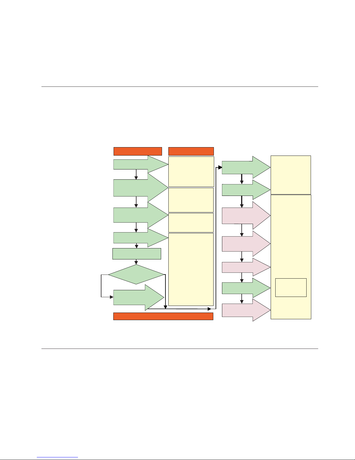
DS4000 installation process overview
The following flow chart gives an overview of the DS4000 hardware and the
DS4000 Storage Manager software installation process. Lined arrows in the flow
chart indicate consecutive steps in the hardware and software installation process.
Labeled arrows indicate which current documents provide detailed information
about those steps.
Install Process Documentation
Plan installation
Connect Power and
Start Server
DS4000 Storage Server
Installation Guide
Complete SM SW
Installation
Configure Storage
Hardware
Online Help
Configure Storage
Subsystems on Host
Verify Server
operation w/ LEDs
Prepare for
Installation of
SM Software
Install and Verify
SM SW on Host and
Workstation
* FC Planning and
Integration: User's Guide
and Svc Info
DS4000 Storage Manager
Concepts Guide
DS4000 Storage Exp Units
Install and User's Guides
DS4000 Fibre Channel
Storage Server
Installation Guides
Fibre Channel Cabling
Instructions
DS4000 and HBA Install
and User's Guides
DS4000 Storage Svr
Installation Guide
DS4000 RAID Controller
Enclosure Unit Install
and User's Guide
Copy Services
User's Guide
DS4000 Storage Manager
DS4000 Storage
Manager Installation
and Support
OS Guides
DS4000 Hardware
Maintenance Manual
DS4000 Problem
Determination Guide
Out-of-Band
In-Band
Make FC Connections
SET Link Speed
(1GB or 2GB)
Install Storage
Server/RAID Controller
Enclosure(s) in Rack
Install Network
Hardware; Prep are
Network Connection
Install Storage
Expansion Unit(s)
Determine
Management
Method
* For pSeries Server and 6227 or 6228 HBA use only
sj001046
DS4000 Storage Server publications
The following tables present an overview of the DS4500, DS4400, DS4300 Fibre
Channel, and DS4100 SATA Storage Server product libraries, as well as other
related documents. Each table lists documents that are included in the libraries and
what common tasks they address.
You can access the documents listed in these tables at one of the following Web
sites:
www-1.ibm.com/servers/storage/support/disk/
Figure 1. Installation process flow by current publications
About this document xvii
Page 20

www.ibm.com/shop/publications/order/
DS4500 storage server library
Table 2 associates each document in the DS4500 (previously FAStT900) storage
server library with its related common user tasks.
Table 2. TotalStorage DS4500 storage server document titles by user tasks
Title User Tasks
Planning Hardware
Installation
Software
Installation
Configuration Operation and
Administration
Diagnosis and
Maintenance
IBM TotalStorage
FAStT900 Installation
and Support Guide,
GC26-7530
U U U
IBM TotalStorage
FAStT900 Fibre
Channel Cabling
Instructions, 24P8135
U U
IBM TotalStorage
FAStT900 Storage
Server User’s Guide,
GC26-7534
U U U
IBM TotalStorage
FAStT FC2-133 Dual
Port Host Bus
Adapter Installation
and User’s Guide,
GC26-7532
U U
IBM FAStT FC2-133
Host Bus Adapter
Installation and
User’s Guide,
48P9823
U U
IBM TotalStorage
FAStT Rack
Mounting
Instructions, 19K0900
U U
IBM FAStT
Management Suite
Java User’s Guide,
32P0081
U U
IBM TotalStorage
DS4000 Hardware
Maintenance Manual,
GC26-7702
U
IBM TotalStorage
DS4000 Problem
Determination Guide,
GC26-7703
U
xviii IBM TotalStorage DS4000: Hardware Maintenance Manual
Page 21

DS4400 storage server library
Table 3 associates each document in the DS4400 (previously FAStT700) storage
server library with its related common user tasks.
Table 3. TotalStorage DS4400 storage server document titles by user tasks
Title User Tasks
Planning Hardware
Installation
Software
Installation
Configuration Operation and
Administration
Diagnosis and
Maintenance
IBM FAStT700 Fibre
Channel Cabling
Instructions, 32P0343
U U
IBM FAStT700 Fibre
Channel Storage
Server User’s Guide,
32P0341
U U U
IBM FAStT FC2-133
Dual Port Host Bus
Adapter Installation
and User’s Guide,
GC26-7532
U U
IBM TotalStorage
FAStT FC2-133 Host
Bus Adapter
Installation and
User’s Guide,
48P9823
U U
IBM FAStT
Management Suite
Java User’s Guide,
32P0081
U U
IBM TotalStorage
DS4000 Hardware
Maintenance Manual,
GC26-7702
U
IBM TotalStorage
DS4000 Problem
Determination Guide,
GC26-7703
U
About this document xix
Page 22

DS4300 storage server library
Table 4 associates each document in the DS4300 (previously FAStT600) storage
server library with its related common user tasks.
Table 4. TotalStorage DS4300 storage server document titles by user tasks
Title User Tasks
Planning Hardware
Installation
Software
Installation
Configuration Operation and
Administration
Diagnosis and
Maintenance
IBM TotalStorage
FAStT600 Fibre
Channel Storage
Server Installation
and User’s Guide,
GC26-7531
U U U
IBM TotalStorage
DS4000 Hardware
Maintenance Manual,
GC26-7702
U
IBM TotalStorage
DS4000 Problem
Determination Guide,
GC26-7703
U
IBM TotalStorage
FAStT FC2-133 Host
Bus Adapter
Installation and
User’s Guide,
48P9823
U U
IBM TotalStorage
FAStT FC2-133 Dual
Port Host Bus
Adapter Installation
and User’s Guide,
GC26-7532
U U
IBM TotalStorage
FAStT600 Rack
Mounting
Instructions, 24P8125
U U
IBM TotalStorage
FAST600 Fibre
Channel Cabling
Instructions, 24P8126
U U
DS4100 storage server library
Table 5 on page xxi associates each document in the DS4100 (previously FAStT100)
storage server library with its related common user tasks.
xx IBM TotalStorage DS4000: Hardware Maintenance Manual
Page 23

Table 5. TotalStorage DS4100 storage server document titles by user tasks
Title User Tasks
Planning Hardware
Installation
Software
Installation
Configuration Operation and
Administration
Diagnosis and
Maintenance
IBM TotalStorage
DS4100 Installation,
User’s, and
Maintenance Guide,
GC26-7712
U U U U
IBM TotalStorage
DS4100 Fibre
Channel Cabling
Instructions, 25R0325
U U
IBM TotalStorage
FAStT FC2-133 Dual
Port Host Bus
Adapter Installation
and User’s Guide,
GC26-7532
U U
IBM FAStT FC2-133
Host Bus Adapter
Installation and
User’s Guide,
48P9823
U U
IBM TotalStorage
DS4000 Hardware
Maintenance Manual,
GC26-7702
U
IBM TotalStorage
DS4000 Problem
Determination Guide,
GC26-7703
U
About this document xxi
Page 24

DS4000-related hardware publications
Table 6 associates each of the following documents related to DS4000 (previously
FAStT) operations with its related common user tasks.
Table 6. TotalStorage DS4000-related document titles by user tasks
Title User Tasks
Planning Hardware
Installation
Software
Installation
Configuration Operation and
Administration
Diagnosis and
Maintenance
IBM Safety
Information,
P48P9741
U
IBM TotalStorage
FAStT Quick Start
Guide, GC26-7662
U U
IBM TotalStorage
DS4000 Fibre
Channel and Serial
ATA Intermix
Premium Feature
Installation Overview
GC26-7713
U U U U
IBM TotalStorage
DS4000 EXP100
Storage Expansion
Unit Installation,
User’s, and
Maintenance Guide,
GC26-7694
U U U U U
Fibre Channel
Solutions - IBM
FAStT EXP500
Installation and
User’s Guide,
59P5637
U U U U U
IBM TotalStorage
FAStT EXP700 and
EXP710 Storage
Expansion Units
Installation, User’s,
and Maintenance
Guide, GC26-7647
U U U U U
IBM TotalStorage
DS4000 Hard Drive
and Storage
Expansion Enclosure
Installation and
Migration Guide,
GC26-7704
U U
IBM Fibre Channel
SAN Configuration
Setup Guide, 25P2509
U U U U
IBM FAStT Host
Adapter Installation
and User’s Guide,
59P5712
U U
xxii IBM TotalStorage DS4000: Hardware Maintenance Manual
Page 25

Table 6. TotalStorage DS4000-related document titles by user tasks (continued)
Title User Tasks
Planning Hardware
Installation
Software
Installation
Configuration Operation and
Administration
Diagnosis and
Maintenance
RS/6000 Eserver
pSeries Fibre Channel
Planning and
Integration: User’s
Guide and Service
Information,
SC23-4329
U U U U
DS4000 Storage Manager Version 9 publications
Table 7 associates each document in the DS4000 Storage Manager (previously
FAStT Storage Manager) library with its related common user tasks.
Table 7. TotalStorage DS4000 Storage Manager Version 9 titles by user tasks
Title User Tasks
Planning Hardware
Installation
Software
Installation
Configuration Operation and
Administration
Diagnosis and
Maintenance
IBM TotalStorage
DS4000 Storage
Manager Version 9
Installation and
Support Guide for
Windows 2000/Server
2003, NetWare, ESX
Server, and Linux,
GC26-7706
U U U
IBM TotalStorage
DS4000 Storage
Manager Version 9
Installation and
Support Guide for
AIX, UNIX, Solaris
and Linux on
POWER, GC26–7705
U U U
IBM TotalStorage
DS4000 Storage
Manager Version 9
Copy Services User’s
Guide, GC26-7707
U U U U
IBM TotalStorage
FAStT Storage
Manager Version 9
Concepts Guide,
GC26-7661
U U U U U U
Notices used in this document
This document can contain the following notices that are designed to highlight key
information:
v Note: These notices provide important tips, guidance, or advice.
About this document xxiii
Page 26

v Important: These notices provide information that might help you avoid
inconvenient or problem situations.
v Attention: These notices indicate possible damage to programs, devices, or data.
An attention notice is placed just before the instruction or situation in which
damage could occur.
v Caution: These statements indicate situations that can be potentially hazardous
to you. A caution statement is placed just before the description of a potentially
hazardous procedure step or situation.
v Danger: These statements indicate situations that can be potentially lethal or
extremely hazardous to you. A danger statement is placed just before the
description of a potentially lethal or extremely hazardous procedure step or
situation.
Getting information, help, and service
If you need help, service, or technical assistance or just want more information
about IBM products, you will find a wide variety of sources available from IBM to
assist you. This section contains information about where to go for additional
information about IBM and IBM products, what to do if you experience a problem
with your IBM Eserver xSeries
™
or IntelliStation
®
system, and whom to call for
service, if it is necessary.
Before you call
Before you call, make sure that you have taken these steps to try to solve the
problem yourself:
v Check all cables to make sure that they are connected.
v Check the power switches to make sure that the system is turned on.
v Use the troubleshooting information in your system documentation, and use the
diagnostic tools that come with your system.
v Check for technical information, hints, tips, and new device drivers at the IBM
Support Web site:
www-1.ibm.com/servers/storage/support/disk/
v Use an IBM discussion forum on the IBM Web site to ask questions.
You
can solve many problems without outside assistance by following the
troubleshooting procedures that IBM provides in the online help or in the
documents that are provided with your system and software. The information that
comes with your system also describes the diagnostic tests that you can perform.
Most xSeries and IntelliStation systems, operating systems, and programs come
with information that contains troubleshooting procedures and explanations of
error messages and error codes. If you suspect a software problem, see the
information for the operating system or program.
Using the documentation
Information about your xSeries or IntelliStation system and preinstalled software, if
any, is available in the documents that come with your system. This includes
printed documents, online documents, readme files, and help files. See the
troubleshooting information in your system documentation for instructions for
using the diagnostic programs. The troubleshooting information or the diagnostic
programs might tell you that you need additional or updated device drivers or
other software.
xxiv IBM TotalStorage DS4000: Hardware Maintenance Manual
Page 27

Web sites
IBM maintains pages on the World Wide Web where you can get the latest
technical information and download device drivers and updates.
v For DS4000 information, go to the following Web site:
www-1.ibm.com/servers/storage/support/disk/
The support page has many sources of information and ways for you to solve
problems, including:
– Diagnosing problems, using the IBM Online Assistant
– Downloading the latest device drivers and updates for your products
– Viewing frequently asked questions (FAQ)
– Viewing hints and tips to help you solve problems
– Participating in IBM discussion forums
– Setting up e-mail notification of technical updates about your products
v You can order publications through the IBM Publications Ordering System at the
following Web site:
www.elink.ibmlink.ibm.com/public/applications/publications/cgibin/pbi.cgi/
v For the latest information about IBM xSeries products, services, and support, go
to the following Web site:
www.ibm.com/eserver/xseries/
v For the latest information about the IBM IntelliStation information, go to the
following Web site:
www.ibm.com/pc/intellistation/
v For the latest information about operating system and HBA support, clustering
support, SAN fabric support, and Storage Manager feature support, see the
TotalStorage DS4000 Interoperability Matrix at the following We b site:
www.storage.ibm.com/disk/fastt/supserver.htm
Software service and support
Through IBM Support Line, for a fee you can get telephone assistance with usage,
configuration, and software problems with xSeries servers, IntelliStation
workstations, and appliances. For information about which products are supported
by Support Line in your country or region, go to the following We b site:
www.ibm.com/services/sl/products/
For more information about the IBM Support Line and other IBM services, go to
the following We b sites:
v www.ibm.com/services/
v www.ibm.com/planetwide/
Hardware service and support
You can receive hardware service through IBM Integrated Technology Services or
through your IBM reseller, if your reseller is authorized by IBM to provide
warranty service. Go to the following Web site for support telephone numbers:
www.ibm.com/planetwide
In the U.S. and Canada, hardware service and support is available 24 hours a day,
7 days a week. In the U.K., these services are available Monday through Friday,
from 9 a.m. to 6 p.m.
About this document xxv
Page 28

Fire suppression systems
A fire suppression system is the responsibility of the customer. The customer’s own
insurance underwriter, local fire marshal, or a local building inspector, or both,
should be consulted in selecting a fire suppression system that provides the correct
level of coverage and protection. IBM designs and manufactures equipment to
internal and external standards that require certain environments for reliable
operation. Because IBM does not test any equipment for compatibility with fire
suppression systems, IBM does not make compatibility claims of any kind nor
does IBM provide recommendations on fire suppression systems.
How to send your comments
Your feedback is important to help us provide the highest quality information. If
you have any comments about this document, you can submit them in one of the
following ways:
v E-mail
Submit your comments electronically to:
starpubs@us.ibm.com
Be sure to include the name and order number of the document and, if
applicable, the specific location of the text you are commenting on, such as a
page number or table number.
v Mail
Fill out the Readers’ Comments form (RCF) at the back of this document and
return it by mail or give it to an IBM representative. If the RCF has been
removed, you can address your comments to:
International Business Machines Corporation
Information Development
Department GZW
9000 South Rita Road
Tucson, Arizona 85744–0001
U.S.A.
When you send information to IBM, you grant IBM a nonexclusive right to use or
distribute the information in any way it believes appropriate without incurring any
obligation to you.
xxvi IBM TotalStorage DS4000: Hardware Maintenance Manual
Page 29

Chapter 1. About hardware maintenance
This hardware maintenance manual contains basic information, such as
specifications and symptom lists, about many of the components of a fibre channel
configuration. Yo u can use this information to complete the tasks given in the
problem determination procedures provided in the IBM TotalStorage DS4000
Problem Determination Guide.
Note: Graphics used in this document are for illustrative purposes only. The
appearance of actual device may differ from the graphic.
The component information that is provided in this document has been extracted
from the individual Hardware Maintenance Manuals or Installation and User’s
Guides for each component. Therefore, you might find it helpful to see the
individual documents for specific components.
Note: For information about how to use and troubleshoot problems with the FC
6228 2 gigabit fibre channel adapter in IBM Eserver pSeries
®
AIX hosts, see
Fibre Channel Planning and Integration: User’s Guide and Service Information,
SC23-4329.
Where to start
Start with the General Checkout sections in each chapter to help you to diagnose
problems with the IBM fibre channel products that this document describes.
For error codes and error messages, see the Symptom-to-FRU Index for the server
that the fibre channel hub, adapter, or RAID controller is connected to.
Related documents
For information about managed hubs and switches that can be in your installation,
see the following publications:
v IBM 3534 SAN Fibre Channel Managed Hub Installation and Service Guide,
SY27-7616
v IBM SAN Fibre Channel Switch 2109 Model S08 Installation and Service Guide,
SC26-7350
v IBM SAN Fibre Channel Switch 2109 Model S16 Installation and Service Guide,
SC26-7352
This installation and service information can be found at the following Web site:
www-1.ibm.com/servers/storage/san/index.html
© Copyright IBM Corp. 2004 1
Page 30

2 IBM TotalStorage DS4000: Hardware Maintenance Manual
Page 31

Chapter 2. Type 3523 Fibre Channel Hub and GBIC
Note: The problem determination (PD) maps found in the IBM TotalStorage DS4000
Problem Determination Guide provide you with additional diagnostic aids.
The type 3523 fibre channel hub and Gigabit Interface Converter (GBIC) are
compatible with the following IBM products:
v Fibre channel PCI adapter (FRU 01K7354) (see Chapter 3 on page 11)
v IBM DS4000 host adapter (FRU 09N7292) (see Chapter 4 on page 13)
v Type 3526 fibre channel RAID controller (see Chapter 6 on page 21)
The
IBM fibre channel hub is a 7-port central interconnection for Fibre Channel
Arbitrated Loops (FC-AL) that follow the ANSI FC-AL standard. Each fibre
channel hub port receives serial data from an attached node and retransmits the
data out of the next hub port to the next node attached in the loop. Each reception
includes data regeneration (both signal timing and amplitude) that supports
full-distance optical links.
The fibre channel hub detects any loop node that is missing or is inoperative and
automatically routes the data to the next operational port and attached node in the
loop. LED indicators provide status information to indicate whether the port is
active or bypassed.
Each port requires a GBIC to connect it to each attached node. The fibre channel
hub supports any combination of short-wave or long-wave optical GBICs. The
GBICs are hot-pluggable into the fibre channel hub, which means you can add host
computers, servers, and storage modules to the arbitrated loop dynamically
without powering off the fibre channel hub or any connected devices. If you
remove a GBIC from a fibre channel hub port, that port is automatically bypassed.
The remaining hub ports continue to operate normally with no degradation of
system performance. Conversely, if you plug a GBIC into the fibre channel hub, it
is automatically inserted and becomes a node on the loop if valid fibre channel
data is received from the device.
Data transfer within the fibre channel hub is implemented in serial differential
Positive Emitter Coupled Logic (PECL) AC coupled logic. Each fibre channel hub
port monitors the serial data input stream as well as the GBIC connected to it.
The following conditions cause the fibre channel hub to bypass a port:
v TX_FAULT: Detects a GBIC transmitter fault
v RX_LOS: Detects a loss of received signal amplitude from the device
v MOD_DEF: Detects the absence of a GBIC
The
fibre channel hub circuitry detects off-frequency data, excessive jitter, or
inadequate edge transition density on a per-port basis. The fibre channel hub uses
the standardized AMP SCA2 20-pin connector to implement hot plugging. Surge
currents, caused by hot plugging, are minimized by slow-start circuitry and a
pin-sequencing procedure on the GBIC. Electrostatic discharge (ESD) transients are
minimized by means of sequenced connector contacts.
The fibre channel hub includes a universal power supply that can operate from 95
to 250 V ac and from 50 to 60 Hz.
© Copyright IBM Corp. 2004 3
Page 32

General checkout
Installation and operational problems in an arbitrated loop environment are
typically caused by one of the following situations:
v Faulty cabling or cable connector
v Incorrect cable plugging
v Faulty GBIC
v Faulty hubs
v Invalid fibre channel signaling from the host bus adapter (HBA) or disk array
v Device driver or microcode conflicts between the HBAs and other devices
The
following information will help you to isolate and correct the physical layer
problems. For protocol-related problems, such as inoperability between devices, see
the documentation that came with the individual devices.
Port Status LEDs
The hub provides two status LEDs for each port (see Table 8). Use these LEDs to
help you quickly diagnose and recover from problems.
The upper, green LED is lit when an operational GBIC is installed. The lower,
amber LED is lit when the port is in the bypass mode. In the bypass mode, a port
is disabled, which prevents erratic signals or data from disrupting loop activity.
The bypass mode could be triggered by the loss of a valid signal or by a GBIC
fault. The combination of green and amber LEDs indicates one of the four
following states.
Table 8. Type 3523 fibre channel hub port status LEDs
Green LED Amber LED Port State
Off Off No GBIC Installed
On Off Operational GBIC; Valid Signal
Off On Faulty GBIC; Port Bypassed
On On Operational GBIC; No Valid Signal; Port Bypassed
Verifying GBIC and cable signal presence
Note: Do not look directly into any fiber cable or GBIC optical output. To view an
optical signal, use a mirror to view the reflected light.
Verifying signal presence
In addition to verifying port LED status, you can verify signal presence by using a
mirror to look for a reflected light at the fiber-optic cable ends and the GBIC
transmitter. To verify signal presence at the hub end of a link, insert a GBIC into
the hub and place a mirror at the bottom of the SC connector. If a signal is present,
you will see a low intensity red light in the mirror reflecting from the GBIC
transmitter. See Figure 2 on page 5.
4 IBM TotalStorage DS4000: Hardware Maintenance Manual
Page 33

Verifying node end
To verify the integrity of the fiber-optic cable at the node end of a link, make sure
the cable is attached to the GBIC at the hub and the hub is turned on. Dual SC
fiber-optic cable connectors are keyed and will insert into a GBIC in one direction
only. Place a mirror at the node end of the link. A low intensity red light is visible
in the mirror reflection of one of the SC leads, as shown in Figure 3.
If a fiber-optic cable has good transmitter output but a broken or degraded receiver
lead, the end node might sense a loop down state. Because the transmitter is good,
the hub responds to the end node valid fibre channel signal and adds the device to
the loop. But, because the end node is not receiving fibre channel signals, it will
stream loop-down sequences onto the loop. This prevents all data communications
among the devices on the loop and will continue to do so until the condition is
corrected.
Verifying hub end
To verify the integrity of the fiber-optic cable at the hub end, make sure the
fiber-optic cable is plugged into the host bus adapter at the host or into a
disk-array controller and that the device is enabled on the loop. Using a mirror,
examine the cable SC leads to verify that a low-intensity red light is visible on the
receiver lead.
Note: Some fiber-optic cables are marked with an A on the receiver lead and a B
on the transmitter lead and are keyed. Some multimode cables plugged into
a GBIC, HBA, or disk array controller are key-oriented with the B lead
inserted into the device transmitter. Place a mirror on the opposite end of
the cable to see the low-intensity red light on the A receiver lead.
Additional service information
This section contains additional service information for the fibre channel hub.
Applications and configurations
The fibre channel hub modular interface provides flexibility and is upgradable to
available short-wave and long-wave optical fibre channel product port interfaces.
Figure 2. Verifying signal presence
Connector
Keys
Figure 3. Verifying node end
Chapter 2. Type 3523 Fibre Channel Hub and GBIC 5
Page 34

Fibre channel products that are commonly interconnected to the fibre channel hub
are fibre channel host bus adapters, FC-AL storage devices, and FC-AL storage
arrays. SCSI initiators (workstations and servers) set up and initiate the transfer of
data to or from the storage devices. The storage devices that receive the requests
made by the SCSI initiators are the SCSI targets. Initiators and targets represent
individual nodes that are linked by the shared FC-AL. See Figure 4.
Power on systems check for the fibre channel hub
Power on the storage modules first, then the controller and the fibre channel hub,
then everything else.
Note: Make sure the fibre channel hub is powered on before the host adapter to
insure proper loop initialization.
Perform the following steps to insure proper operation of the fibre channel hub:
1. Connect the power cord to the fibre channel hub, then to the electrical outlet.
See Figure 5.
2. Power on the attached FC-AL compatible nodes.
3. Check the Device Active (green) LEDs on the fibre channel hub ports. See
Figure 6 on page 7.
Figure 4. Type 3523 fibre channel hub
Power Connector
Figure 5. Type 3523 fibre channel hub power connector
6 IBM TotalStorage DS4000: Hardware Maintenance Manual
Page 35

LED On
This indicates that a GBIC is present and functioning properly.
LED Off
This indicates a fault condition. Examples of a fault condition include: a
GBIC transmitter fault, an improperly seated GBIC, an absent GBIC, or
another failed device. The port will be in the bypass state, which
precludes the port from participating in the FC-AL. This is the normal
status of operation for fibre channel hub ports in which GBICs are not
installed.
Note:
FC-AL compatible nodes must perform loop initialization procedures at
power on to function properly on the loop. FC-AL nodes also perform
loop initialization or reinitialization depending on their prior state of
operation.
4. Check the Port Bypass (amber) LEDs. See Figure 7.
LED On
If the Active (green) LED of the port is off, the port is nonoperational
and the Bypass (amber) LED for the port is on. If a properly
functioning port (the Active green LED is on) with a GBIC present also
has the Bypass LED on, either the loss of signal or poor signal integrity
has caused the port to go into the bypass state. When the port is in this
state, it cannot participate in the FC-AL.
The bypass state is also the normal status condition when no GBIC is
present in the port, a GBIC is present but not attached to a FC-AL
node, or a GBIC is attached to a cable assembly with nothing attached
at the opposite end. Replacing such a port (or removing and reinserting
the GBIC into the same port twice) is considered to be a loop
configuration change that invokes the Loop Initialization Procedure.
LED Off
This indicates that the fibre channel hub port and device are fully
operational and actively participating in the FC-AL.
5.
The FC-AL should be fully operational. Check that proper loop discovery has
taken place and all required devices are participating in the loop. Some host
bus adapters might provide this level of functionality or it might be resident in
the application software on the host operating system.
Active On
Green LEDs on Top Row
Figure 6. Type 3523 fibre channel hub active LEDs
Bypass
Amber LEDs on Bottom Row
Figure 7. Type 3523 fibre channel hub port bypass LEDs
Chapter 2. Type 3523 Fibre Channel Hub and GBIC 7
Page 36

Symptom-to-FRU index
The Symptom-to-FRU index (see Table 9) lists symptoms, errors, and the possible
causes. The most likely cause is listed first.
The PD maps found in the IBM TotalStorage DS4000 Problem Determination Guide
provide you with additional diagnostic aids.
Note:
1. Always start with the “General checkout” on page 4. For IBM devices
not supported by this index, see the manual for that device.
2. Do not look directly into any fiber cable or GBIC optical output. Read
“Notices” on page 137. To view an optical signal, use a mirror to view
the reflected light.
Table 9. Symptom-to-FRU index for Type 3523 fibre channel hub and GBIC
Problem Action/FRU
GBIC installed in one or
more ports but no LED is
lit.
1. Power cord
2. Power source
GBIC installed but only the
amber LED is lit.
1. Reseat GBIC
2. GBIC
GBIC installed and both
green and amber LEDs are
lit.
The hub is not receiving a valid fibre channel signal from the end node. Perform
the following steps:
1. Unplug the fiber cable from the node and, using a mirror, verify that an optical
signal is present on the cable. If no red light is visible, replace the cable.
2. Using a mirror, examine the SC connectors on the HBA or disk controller. If no
red light is visible, check the HBA or disk controller.
3. If a light is present on both the cable lead and the end node, check the HBA or the
disk controller.
GBIC is installed, only the
green LED is lit, but no
communication occurs
between the devices.
The hub is receiving a valid fibre channel signal from the end device, but no
upper-level protocols are active. Perform the following steps:
1. Verify that the proper HBA device drivers are loaded for the appropriate
operating system and that the host has been configured to recognize the attached
disk devices.
2. Unplug the fiber cable from the end node and verify that an optical signal is
present on the cable lead. If no signal is present, the lead of the cable might be
defective. Replace the cable.
8 IBM TotalStorage DS4000: Hardware Maintenance Manual
Page 37

Parts listing (Type 3523 fibre channel hub and GBIC)
Figure 8 and the following table provide a parts listing for the type 3523 fibre
channel hub and GBIC.
Index Fibre channel hub (Type 3523) FRU
1 Port Fibre Hub Assembly 01K6738
2 Hub Tray Assembly 10L7042
3 Hub Tray Bezel 10L7041
4 Short-Wave GBIC 03K9206
Long-Wave GBIC (option) 03K9208
Misc. Hardware Kit 01K6739
1
2
3
4
Figure 8. Type 3523 fibre channel hub parts listing
Chapter 2. Type 3523 Fibre Channel Hub and GBIC 9
Page 38

10 IBM TotalStorage DS4000: Hardware Maintenance Manual
Page 39

Chapter 3. Fibre Channel PCI Adapter
Note: The PD maps found in the IBM TotalStorage DS4000 Problem Determination
Guide provide you with additional diagnostic aids.
The fibre channel PCI adapter (FRU 01K7354) is compatible with the following
IBM products:
v Type 3523 fibre channel hub and GBIC (see Chapter 2 on page 3)
v Type 3526 fibre channel RAID controller (see Chapter 6 on page 21)
v Type 2109 fibre channel switch
v Type 3534 managed hub
The
IBM TotalStorage DS4000 Problem Determination Guide provides detailed
configuration information for advanced users who want to use IBM Fast!UTIL to
customize the configuration of the fibre channel PCI adapter (FRU 01K7354).
General checkout
The following three basic types of problems can cause the fibre channel PCI
adapter to function incorrectly:
v Hardware problems
v System configuration problems
v Fibre channel problems
Hardware problems
The following list will help you determine whether a problem was caused by the
hardware:
v Verify that all of the adapters are installed securely.
v Verify that all of the cables are connected securely to the correct connectors. Be
sure that the SC connectors that attach from the J1 connector on the fibre
channel PCI adapter to the device are connected correctly.
v Verify that the fibre channel PCI adapter is installed correctly and seated firmly
in the expansion slot.
v Verify that all peripheral devices are properly powered on. See the IBM
TotalStorage DS4000 Problem Determination Guide for information about how to
use IBM Fast!UTIL to display attached devices.
System configuration problems
To determine whether a problem was caused by the system configuration, check
the system board to make sure it is configured properly (see the appropriate IBM
TotalStorage DS4000 Product Installation Guide).
Fibre channel problems
To determine whether a problem was caused by the fibre channel, verify that all of
the FC devices were powered on before you powered on the server.
Additional service information
The following information supports the fibre channel PCI adapter.
© Copyright IBM Corp. 2004 11
Page 40

The IBM fibre channel PCI adapter operating environment and specification
information is detailed in Table 10 and Table 11.
Table 10. Fibre channel PCI adapter operating environment
Environment Minimum Maximum
Operating temperature 0° C (32° F) 55° C (131° F)
Storage temperature -20° C (-4° F) 70° C (158° F)
Relative humidity
(noncondensing)
10% 90%
Storage humidity
(noncondensing)
5% 95%
Table 11 . Fibre channel PCI adapter specifications
Type Specification
Host bus Conforms to PCI Local Bus Specification, revision 2.1
PCI signaling
environment
3.3 V and 5.0 V buses supported
PCI transfer rate 264 MB per second maximum burst rate for 33 MHz operation
(ISP2100 chip)
Fibre channel
specifications
Bus type: fiber-optic media (QLA2100F)
Bus transfer rate: 100 MB per second maximum
Central processing unit
(CPU)
Single chip design that includes a RISC processor, fibre channel
protocol manager, PCI DMA controller, and 1-gigabit transceivers
Host data transfer 64-bit, bus master DMA data transfers to 264 MB per second
RAM 128 KB of SRAM
BIOS ROM 128 KB of flash ROM in two 64-KB, software selectable banks. The
flash is field-programmable.
NVRAM 256 bytes, field-programmable
Onboard DMA Three independent DMA channels: two data and one command.
Integrated 4-KB frame buffer FIFO for each data channel
Connectors (external) SC-style connector that supports non-OFC, multimode fiber-optic
cabling using 1x9 fiber-optic transceiver module. Total cable
length cannot exceed 500 meters.
Form factor 17.78 cm x 10.67 cm (7.0 in. x 4.2 in.)
Operating power Less than 15 watts
12 IBM TotalStorage DS4000: Hardware Maintenance Manual
Page 41

Chapter 4. DS4000 Host Adapter
Note: The PD maps found in the IBM TotalStorage DS4000 Problem Determination
Guide provide you with additional diagnostic aids.
The IBM DS4000 host adapter (FRU 09N7292) is a high-performance, direct
memory access (DMA), bus-master host adapter designed for high-end systems.
The function and performance are derived from the ISP2200A chip, making the
DS4000 host adapter a leading-edge host adapter.
The ISP2200A chip combines a powerful RISC processor, a fibre protocol module
(FPM) with gigabit transceivers, and a 64-bit peripheral component interconnect
(PCI) local bus interface in a single-chip solution. The DS4000 host adapter
supports all fibre channel peripheral devices that support private-loop direct attach
(PLDA) and fabric-loop attach (FLA).
The IBM DS4000 host adapter is compatible with the following IBM products:
v Type 3526 fibre channel RAID controller (see Chapter 6 on page 21)
v Type 3552 FAStT500 RAID controller (see Chapter 8 on page 47)
v FAStT200 Type 3542 and FAStT200 HA Type 3542 (see Chapter 7 on page 35)
v Type 2109 fibre channel switch
v Type 3534 managed hub
The IBM TotalStorage DS4000 Problem Determination Guide provides detailed
configuration information for advanced users who want to use IBM Fast!UTIL to
customize the configuration of the fibre channel adapter (FRU 09N7292).
General checkout
The following types of problems can cause the adapter to malfunction:
v Hardware problems
v System configuration problems
v Fibre channel problems
Hardware problems
The following list will help you determine whether your installation problem is
caused by the hardware:
v Verify that all adapters are installed securely.
v Verify that all cables are attached securely to the correct connectors. Be sure that
the FC connectors that attach from the J1 connector on the adapter to the device
are connected securely.
v Verify that the adapter is installed correctly and fully seated in the expansion
slot. Check for interference due to nonstandard PCI connectors.
v Verify that all peripheral devices are turned on. See the IBM TotalStorage DS4000
Problem Determination Guide for information about how to use IBM Fast!UTIL to
display attached devices.
© Copyright IBM Corp. 2004 13
Page 42

System configuration problems
To determine whether a problem was caused by the system configuration, check
the system board to make sure that it was configured properly (see the appropriate
IBM TotalStorage DS4000 Product Installation Guide).
Fibre channel problems
To determine whether your installation problem is caused by the fibre channel,
verify that all of the fibre channel devices were turned on before you turned on the
server. Also, ensure that all cables are connected properly.
The PD maps found in the IBM TotalStorage DS4000 Problem Determination Guide
provide you with additional diagnostic aids.
Additional service information
The following information supports the DS4000 host adapter.
This section contains the DS4000 host adapter operating environment and
specification information.
Table 12. DS4000 host adapter operating environment
Environment Minimum Maximum
Operating temperature 0° C (32° F) 55° C (131° F)
Storage temperature -20° C (-4° F) 70° C (158° F)
Relative humidity (noncondensing) 10% 90%
Storage humidity (noncondensing) 5% 95%
Table 13. DS4000 host adapter specifications
Type Specification
Host bus Conforms to PCI Local Bus Specification, revision 2.2
PCI signaling
environment
3.3 V and 5.0 V buses supported
PCI transfer rate
v 264 MB per second maximum burst rate for 33 MHz operation
(ISP2200A chip)
v Supports dual address bus cycles
Fibre channel
specifications
v Bus type: fiber-optic media (shortwave 50 micron)
v Bus transfer rate: 100 MB per second maximum (200 full-duplex)
v Supports both FCP-SCSI and IP protocols
v Supports point-to-point fabric connection: F-Port Fabric Login
v Supports FC-AL public loop profile: FL-Port Login
v Supports fibre channel services class 2 and 3
v FCP SCSI initiator and target operation
v Full-duplex operation
Processor Single chip design that includes a RISC processor, fibre channel
protocol manager, PCI DMA controller, and 1-gigabit transceivers
Host data
transfer
64-bit, bus master DMA data transfers to 528 MB per second
RAM 128 KB of SRAM
14 IBM TotalStorage DS4000: Hardware Maintenance Manual
Page 43

Table 13. DS4000 host adapter specifications (continued)
Type Specification
BIOS ROM 128 KB of flash ROM in two 64 KB, software selectable banks. The flash
is field-programmable.
NVRAM 256 bytes, field-programmable
Onboard DMA Three independent DMA channels: two data and one command.
Integrated 4 KB frame buffer FIFO for each data channel
Connectors
(external)
v SC-style connector that supports non-OFC, multimode fiber-optic
cabling using 1x9 fiber-optic transceiver module
v Total cable length cannot exceed 500 meters
v Tw o three-position, point-to-point cable (internal)
Form factor 17.8 cm x 10.7 cm (7.0 in. x 4.2 in.)
Operating power Less than 15 watts
Other compliance
v PCI 98, including ACPI
v Less than 28% processor utilization as measured in a TPCC
benchmark
v Operation system support for Microsoft
®
Windows NT
®
version 4,
Windows
®
2000 version 1, NetWare version 4.x and 5.x, SCO
UnixWare version 7.x
v Worldwide agency compliance as defined for IBM products
v 100% Plug and Play compatibility with your existing fibre channel
RAID controller
Chapter 4. DS4000 Host Adapter 15
Page 44

16 IBM TotalStorage DS4000: Hardware Maintenance Manual
Page 45

Chapter 5. DS4000 FC2-133 Host Bus Adapter
Note: The PD maps found in the IBM TotalStorage DS4000 Problem Determination
Guide provide you with additional diagnostic aids.
The IBM DS4000 FC2-133 host bus adapter (single port model, FRU 24P0962) is a 2
Gbps high-performance, direct memory access (DMA), bus master, fibre channel
host adapter designed for high-end systems. The function and performance are
derived from the ISP2312/ISP2340 chips, making the IBM DS4000 FC2-133 host bus
adapter a leading-edge host adapter.
The ISP2312/ISP2340 chips combine a powerful, reduced instruction set computer
(RISC) processor, a fibre channel protocol manager (FPM) with one 2 Gbps fibre
channel transceiver, and a peripheral component interconnect (PCI) or peripheral
component interconnect-extended (PCI-X) local bus interface in a single-chip
solution. The IBM DS4000 FC2-133 host bus adapter supports all fibre channel (FC)
peripheral devices that support private-loop direct attach (PLDA) and fabric-loop
attach (FLA).
The IBM TotalStorage DS4000 Problem Determination Guide provides detailed
configuration information for advanced users who want to use IBM Fast!UTIL to
customize the configuration of the DS4000 FC2-133 host bus adapter.
Note: For information about how to use and troubleshoot problems with the FC
6228 2 Gigabit fibre channel adapter in pSeries AIX
®
hosts, see Fibre Channel
Planning and Integration: User’s Guide and Service Information, SC23-4329-03.
General checkout
The following types of installation problems might cause your DS4000 FC2-133
host bus adapter to function incorrectly:
v Hardware problems
v System configuration problems
v Fibre channel problems
If you are having problems, use the following information to help you determine
the cause of the problem and the action to take.
Hardware problems
Take the following actions to determine if your installation problem is caused by
the hardware:
v Verify that all adapters are installed securely.
v Verify that all cables are attached securely to the correct connectors. Be sure that
one end of the LC-LC fibre channel cable is attached to the optical interface
connector (located at J1 on the adapter) and that the other end is connected to
the fibre channel device.
v Verify that the DS4000 FC2-133 host bus adapter is installed correctly and is
fully seated in the expansion slot. Check for interference due to nonstandard PCI
connectors.
v Verify that the Fast!UTIL data-rate setting is correct. The Fast!UTIL data-rate
setting must match the speed of the device to which you are connected.
© Copyright IBM Corp. 2004 17
Page 46

v Verify that all peripheral devices are turned on. See the IBM TotalStorage DS4000
Problem Determination Guide for information about how to use Fast!UTIL to
display attached fibre channel devices.
System configuration problems
To verify that your installation problem is caused by the system configuration,
check your server to ensure that it is configured properly (see the appropriate IBM
TotalStorage DS4000 Product Installation Guide).
Note: All PCI-compliant and PCI-X-compliant systems automatically detect 32-bit
or 64-bit adapters and set the appropriate bus speed (for example, 66 MHz
or 133 MHz).
Fibre channel problems
To determine if your installation problem is caused by an attached fibre channel
device, perform the following actions:
v Verify that all of the fibre channel devices were turned on before you turned on
the server.
v Ensure that all cables are connected properly.
v Verify that you configured your RAID storage subsystems using the utilities that
the manufacturer provided.
v If your fibre channel switch supports zoning, make sure that your peripheral
device is configured to the same switch zone as the DS4000 FC2-133 host bus
adapter. For more information, see your fibre channel switch documentation.
Additional service information
Table 14 and Table 15 contain the DS4000 FC2-133 host bus adapter operating
environment and specification information.
Table 14. DS4000 FC2-133 host bus adapter operating environment
Environment Minimum Maximum
Operating temperature 0° C (32° F) 55° C (131° F)
Storage temperature -20° C (-4° F) 70° C (158° F)
Relative humidity (noncondensing) 10% 90%
Storage humidity (noncondensing) 5% 95%
Table 15. DS4000 FC2-133 host bus adapter specifications
Type Specification
Host bus Conforms to Intel
™
PCI Local Bus Specification, revision 2.2
and the PCI-X Addendum, revision 1.0.
PCI/PCI-X signaling
environment
3.3 V and 5.0 V buses supported
PCI/PCI-X transfer rate
v Support for 32 bit and 64 bit PCI bus at 33 MHz and 64
MHz
v Support for 64 bit PCI-X bus at 50 MHz, 100 MHz, and
133 MHz
v PCI transfer rate 264 MB per second maximum burst rate
for 33 MHz operation (ISP2312/ISP2340 chips)
v Support for dual address bus cycles
18 IBM TotalStorage DS4000: Hardware Maintenance Manual
Page 47

Table 15. DS4000 FC2-133 host bus adapter specifications (continued)
Type Specification
Fibre channel specifications
v Fiber-optic media (shortwave multimode 50 micron cable)
v Bus transfer rate: 200 MBps maximum at half-duplex and
at 400 MBps maximum full-duplex
v Interface chip: ISP2312/ISP2340 (PCI-X QLA23xx boards)
v Support for both FCP-SCSI and IP protocols
v Support for point-to-point fabric connection: F-port Fabric
Login
v Support for FC-AL public loop profile: FL-port Login
v Support for fibre channel services class 2 and 3
v Support for FCP SCSI initiator and target operation
v Support for full-duplex operation
Processor Single-chip design that includes a RISC processor, fibre
channel protocol manager, PCI/PCI-X DMA controller, and
integrated serializer/deserializer (SERDES) and electrical
transceivers that can auto-negotiate a data rate of 2 Gbps
Host data transfer 64-bit, bus-master DMA data transfers to 528 MBps
RAM 256 KB of SRAM supporting parity protection
BIOS ROM 128 KB of flash ROM in two 64 KB, software selectable
banks. The flash is field programmable.
NVRAM 256 bytes, field-programmable
Onboard DMA Five-channel DMA controller: two data, one command, one
auto-DMA request, and one auto-DMA response
Frame buffer FIFO Integrated 4 KB transmit and 6 KB receive frame buffer
first-in first-out (FIFO) for each data channel
Connectors (external)
v LC-style connector that supports non-OFC, multimode
fiber-optic cabling using a small form factor (SFF)
fiber-optic transceiver module.
v Total cable length cannot exceed 500 m
Form factor 5.15 cm x 16.75 cm (2.5 in. x 6.7 in.)
Operating power Less than 15 watts
Chapter 5. DS4000 FC2-133 Host Bus Adapter 19
Page 48

20 IBM TotalStorage DS4000: Hardware Maintenance Manual
Page 49

Chapter 6. Type 3526 Fibre Channel RAID Controller
The Type 3526 fibre channel RAID controller is compatible with the following IBM
products:
v Type 3523 fibre channel hub and GBIC (see Chapter 2 on page 3)
v Fibre channel PCI adapter (FRU 01K7354) (see Chapter 3 on page 11)
v IBM DS4000 host adapter (FRU 09N7292) (see Chapter 4 on page 13)
v Type 2109 fibre channel switch
v Type 3534 managed hub
General checkout
Use the status LEDs and the “Symptom-to-FRU index” on page 32 to diagnose
problems.
Note: The PD maps found in the IBM TotalStorage DS4000 Problem Determination
Guide provide you with additional diagnostic aids.
The LEDs of the control unit indicate the hardware status:
v Green LED indicates normal operation
v Amber LED indicates a hardware problem
The
LEDs on the controller unit indicate the status of the controller unit and its
individual components. The green LEDs indicate a normal operating status; amber
LEDs indicate a hardware fault. Check all of the LEDs on the front and back of the
controller unit when it is powered on.
Notes:
1. If power was just applied to the controller unit, the green and amber LEDs
might turn on and off intermittently. Wait until the controller unit finishes
powering up before you begin checking for faults.
2. To view the controller Customer Replaceable Unit (CRU) LEDs, the front cover
must be removed from the controller unit.
Also use LEDs on the front cover, controller CRUs, and drive units (if applicable)
to determine whether the controllers and drives are responding to I/O
transmissions from the host.
The following list describes LED activities:
v If a Fast Write Cache operation to the controller unit (or attached drive units), or
if other I/O activity is in progress, then you might see several green LEDs
blinking, including: the Fast Write Cache LED (on the front cover), controller
CRU status LEDs, or applicable drive activity LEDs.
v The green Heartbeat LEDs on the controller CRUs blink continuously. The
number and pattern of green status LEDs lit on the controllers depend on how
the system is configured. An active controller will not have the same status
LEDs lit as a passive controller. See the appropriate IBM TotalStorage DS4000
Product Installation Guide.
© Copyright IBM Corp. 2004 21
Page 50

Additional service information
This section provides additional service information about the Type 3526 fibre
channel RAID controller.
Powering on the controller
Note: All drive modules must be powered on before you power on the controller.
The controller might take from three to 10 seconds to power on. During this time,
the amber and green LEDs on the controller unit flash.
After power on, check all fault LEDs to make sure they are off. If a fault LED is
on, see the “Symptom-to-FRU index” on page 32.
Recovering from a power supply shutdown
Both power supplies have a built-in temperature sensor designed to prevent the
power supplies from overheating. If a temperature sensor detects an
over-temperature condition (ambient air temperature of 70° C (158° F) or above),
the overheated power supply automatically shuts down. The other power supply
remains on as long as its temperature remains below 70° C (158° F). If not, the
second power supply shuts down, which turns off all power to the controller unit.
After the air temperature cools to below 70° C (158° F), the power supplies
automatically restart. An automatic restart resets the controllers, attempts to spin
up the drives (which has no effect on the drives if they are already running), and
returns the controller unit to a normal operating state. Typically, you will not need
to perform recovery procedures after an automatic power supply shutdown and
restart.
After a power supply shutdown, check all controller LEDs.
If the power supply power LED is off, or the amber power supply LED on the
front cover is on, go to the “Symptom-to-FRU index” on page 32.
Connectors and host IDs
The host ID switches and connectors for interface cables are on the connector plate
located on the back of the controller unit.
Host and drive ID numbers
Each controller must have a unique Fibre Host ID number (see Figure 9 on page
23). The Host ID numbers assigned to each controller are based on two elements:
v Host ID numbers set through hardware switches on the controller unit. Five
Host ID switches allow you to set ID numbers 0 through 127 for each controller.
The factory default settings are ID #5 for Controller A and ID #4 for controller B.
v Software algorithms that calculate the actual fibre channel address, based on the
controller unit’s hardware settings and position on the loop or hub
Note:
The preferred ID is assigned on the fibre channel loop unless it is already
being used. If the ID is already in use, a soft ID is assigned.
22 IBM TotalStorage DS4000: Hardware Maintenance Manual
Page 51

Fibre channel host cable requirements
For the Type 3526 fibre channel RAID controller, you must use multi-mode,
50-micrometer fiber-optic cable and a Media Interface Adapter (MIA), shown in
Figure 10.
Table 16 provides specifications for the MIA.
Table 16. Type 3526 fibre channel RAID controller MIA specifications
Cable Media type Data size
Transfer
speed Range
Fiber-optic (multi-mode,
50-micrometer)
Short-wave
laser
100 MBps 1062.5
Mbaud
up to 500 m
(1640 ft.)
LVD-SCSI drive cable requirements
To connect the controller unit to a drive module, you must use 68-pin, VHDCI
(very high density cable interface) LVD, Ultra 2 SCSI cables. The controller unit has
six drive connectors that support 16-bit interface protocols. Each connector
represents a single drive channel that supports up to 10 drives per channel for a
total of 60 drives.
Figure 9. Fibre Host ID
Figure 10. Media Interface Adapter
Chapter 6. Type 3526 Fibre Channel RAID Controller 23
Page 52

Specifications
Size
v With front panel:
– Depth: 610 mm (24 in.)
– Height: 174 mm (6.8 in.)
– Width: 482 mm (19 in.)
Weight
v Controller unit maximum weight: 34.5 kg (76 lb)
v Controller unit empty: 14.3 kg (31.6 lb)
v Battery: 9.7 kg (21.4 lb)
Electrical
Input
v Sign-wave input (50 to 60 Hz)
– Low range: Minimum: 90 V ac Maximum: 127 V ac
– High range: Minimum: 198 V ac Maximum: 257 V ac
v
Input Kilovolt-amperes (kVA) approximately:
– Minimum configuration: 0.06 kVA
– Maximum configuration: 0.39 kVA
Environment
v Air temperature:
– hub on: 10° to 35° C (50° to 95° F) Altitude: 0 to 914 m (3000 ft.)
– hub on: 10° to 32° C (50° to 90° F) Altitude: 914 m (3000 ft.) to 2133 m (7000
ft.)
v
Humidity:
– 8% to 80%
Heat
Output
v Approximate heat output in British Thermal Units (BTU) per hour:
– Maximum configuration: 731.8 BTU (214 watts)
Acoustical
Noise Emissions Values
v Sound Power (idling and operating):
– 6.4 bels
v
Sound Pressure (idling and operating):
– 50 dBA
Tested configurations
The following configurations (Figure 11 on page 25 through Figure 22 on page 31)
are for the Type 3526 fibre channel RAID controller.
24 IBM TotalStorage DS4000: Hardware Maintenance Manual
Page 53

Basic Configuration
3526
RAID Controller Unit
Ctrl
A
EXP10, 15 or 200
(up to 6 units)
FC Host adapter
Note: Basic as shipped, single controller, no hubs or switches
Figure 11. Type 3526 fibre channel RAID controller basic configuration
FC host adapter
FC host adapter
Note 1
Note 1: Adapters can be in the same or different systems; choice affects total redundancy
Note 2: No hubs or switches
Basic Dual Controller Configuration
3526
RAID Controller Unit
EXP10, 15 or 200
(up to 6 units)
Note 3: For max redundancy on the drive side use orthagonal striping (see
chart)
Note 4: This config does not provide for “NO single point of failure”
orthagonal striping
Ctrl
B
Ctrl
A
Figure 12. Type 3526 fibre channel RAID controller basic dual controller configuration
Chapter 6. Type 3526 Fibre Channel RAID Controller 25
Page 54

...
...
...
...
...
...
SCSI Channel 1
SCSI Channel 2
SCSI Channel 3
SCSI Channel 4
SCSI Channel 5
SCSI Channel 6
Data striped across channels
EXP10, 15 or 200
Orthogonal Data Striping
Figure 13. Type 3526 fibre channel RAID controller orthogonal data striping
26 IBM TotalStorage DS4000: Hardware Maintenance Manual
Page 55

Simple Fully Redundant
Redundant
Servers
,
FC host adapter
FC host adapter
FC host adapter
FC host adapter
3526
RAID Controller Unit
EXP10, 15 or 200
(up to 6 units)
Hub/switch
Ctrl
B
Ctrl
A
Hub/switch
Note 1: Since disks are seen from multiple places some form of protection such as MSCS, storage partitioning, Sanergy,
Oracle etc must be used.
Note 2: For best performance and managibility, a managed hub switch is preferred.
Note 3: Always try to keep connections to hub on adjacent ports and unplug all unused GBICs
Figure 14. Type 3526 fibre channel RAID controller simple fully redundant
Cluster/Non-Cluster Share
Managed Hub/Switch
Managed Hub/Switch
Clus1
Notes 1
File 1
DB 1
Clus1
LD1
Notes 1
File 1
DB 1
Partition
s1-4
FC host adapter
FC host adapter
FC host adapter
FC host adapter
FC host adapter
FC host adapter
FC host adapter
FC host adapter
FC host adapter
FC host adapter
1
2
3
4
Note : Factors such as performance and number of storage partitions
influence the number and type of nodes.
LD2
3526
RAID Controller Unit
Ctrl
A
EXP10, 15 or 200
(up to 6 units)
Ctrl
B
Figure 15. Type 3526 fibre channel RAID controller cluster/non-cluster share
Chapter 6. Type 3526 Fibre Channel RAID Controller 27
Page 56

Multi-MSCS No External Hubs
FC host adapter
FC host adapter
FC host adapter
FC host adapter
FC host adapter
FC host adapter
FC host adapter
FC host adapter
Clus1
Clus2
LD1 LD2
1
2
LD3 LD4
Clus1
Clus2
Notes:2partitions shown; Clus1 partition separate from Clus2 partition.
LD is a logical drive
3526
RAID Controller Unit
Ctrl
A
EXP10, 15 or 200
(upto6units)
Ctrl
B
Managed Hub/Switch
Managed Hub/Switch
Figure 16. Type 3526 fibre channel RAID controller multi-MSCS no external hubs
FC
Switches
Multi-MSCS extended
FC host adapter
FC host adapter
FC host adapter
FC host adapter
Notes :
- Each group of 4 ports on the switches (
) can support one cluster element (
)
red dash box
black dash box
- Storage partitioning is used to separate clusters
- Match performance needs of servers to max I/o available from 60 drives
- You may use some the switch ports to add 3526 units rather than hosts. Extending this to 16 port switches allows more of both
3526
RAID Controller Unit
Ctrl
A
EXP10, 15 or 200
(upto6units)
Ctrl
B
Figure 17. Type 3526 fibre channel RAID controller multi-MSCS extended
28 IBM TotalStorage DS4000: Hardware Maintenance Manual
Page 57

Notes: Running Cornhusker Software
4 to 8 node configs are supported
8 port Managed hubs or switches can be used as shown
Using 16 port switches removes need to cascade
Performance would be best with switches
HARP
HARP
HARP
HARP
HARP
HARP
HARP
HARP
HARP
HARP
HARP
HARP
HARP
HARP
HARP
HARP
ID 0
ID 0
ID 1
ID 1
ID 2
ID 3
ID 4
ID 5
ID 6
ID 7
ID 2
ID 3
ID 4
ID 5
ID 6
ID 7
ID 0
ID 7
Hub/switch 1
Hub/switch 2
ID 1
ID 2
ID 3
ID 4
ID 5
ID 6
Cntrl A or B
Managed hub/switch physical V
iew
Managed hub/switch logical View
3526
RAID Controller Unit
Ctrl
A
EXP10, 15 or 200
(upto6units)
Ctrl
B
Cornhusker configuration
Figure 18. Type 3526 fibre channel RAID controller cornhusker configuration
To m
Jim
Bill
Al
Al
Jim
Bill
To m
FC host adapter
FC host adapter
FC host adapter
FC host adapter
FC host adapter
FC host adapter
FC host adapter
FC host adapter
Notes:4partitions shown; 4 available in base
3526
RAID Controller Unit
Ctrl
A
EXP10, 15 or 200
(up to 6 units)
Ctrl
B
Managed Hub/Switch
Managed Hub/Switch
Base Storage Partitions
Figure 19. Type 3526 fibre channel RAID controller basic storage partitions
Chapter 6. Type 3526 Fibre Channel RAID Controller 29
Page 58

Capacity Configuration
Redundant
Servers
FC host adapter
FC host adapter
FC host adapter
FC host adapter
EXP10, 15 or 200
(up to 6 units)
3526
RAID Controller Unit
EXP10, 15 or 200
(up to 6 units)
EXP10, 15 or 200
(up to 6 units)
EXP10, 15 or 200
(up to 6 units)
EXP10, 15 or 200
(up to 6 units)
EXP10, 15 or 200
(up to 6 units)
60 - 36 GBdrives
60 - 36 GBdrives
60 - 36 GBdrives
60 - 36 GBdrives
Ctrl
A
Ctrl
A
Ctrl
A
Ctrl
A
Ctrl
A
Ctrl
A
Ctrl
B
Ctrl
B
Ctrl
B
Ctrl
B
Ctrl
B
Ctrl
B
10.9TB usable total
FC switch
FC switch
Figure 20. Type 3526 fibre channel RAID controller capacity configuration
SAN - Using Partitions of Clusters
Note: Storage partitioning and switch zoning are used to configure and run
Servers
N
O
T
E
S
N
O
T
E
S
N
O
T
E
S
N
O
T
E
S
F
I
L
E
F
I
L
E
F
I
L
E
F
I
L
E
F
I
L
E
F
I
L
E
F
I
L
E
F
I
L
E
16 port Sw 16 port Sw 16 port Sw 16 port Sw
Controller A Controller A Controller A Controller A Controller A Controller A
Controller BController BController BController BController BController B
File/Print
Storage
File/Print
Storage
File/Print
Storage
File/Print
Storage
Notes
Storage
Notes
Storage
Figure 21. Type 3526 fibre channel RAID controller SAN - Using partitions of clusters
30 IBM TotalStorage DS4000: Hardware Maintenance Manual
Page 59

Note 1:
Mirroring is done over IP using Gigabit ethernet
Note 2:
Requires Legato LME and MSCS
Legato HA/Replication for MSCS
Primary writes over FCP
Client Interconnect
Private Interconnect
Primary writes over FCP
Mirrored writes over IP
Site A Site B
Up to 10Km
FC-AL
Ethernet, Token Ring, etc.
Gigabit Ethernet
Figure 22. Type 3526 fibre channel RAID controller Legato HA/replication for MSCS
Chapter 6. Type 3526 Fibre Channel RAID Controller 31
Page 60

Symptom-to-FRU index
The Symptom-to-FRU index (Table 17) lists symptoms and the possible causes. The
most likely cause is listed first.
The PD maps found in the IBM TotalStorage DS4000 Problem Determination Guide
also provide you with additional diagnostic aids.
Notes:
1. Always start with the “General checkout” on page 21. For IBM devices not
supported by this index, see the manual for that device.
2. Do not look directly into any fiber cable or GBIC optical output. Read “Notices”
on page 137. To view an optical signal, use a mirror to view the reflected light.
Table 17. Symptom-to-FRU index for Type 3526 fibre channel RAID controller
Problem Action/FRU
Controller LED (front cover) is on.
1. Reseat Controller CRU
2. Place Controller online using DS4000 Storage Manager
GUI
3. If in passive mode, check Fibre path/GBIC
4. Controller CRU
Software issued a controller error message.
1. Check Controller Fan
2. Controller CRU
Software errors occur when attempting to access
controllers or drives.
1. Check appropriate software and documentation to make
sure the system is set up correctly and the proper
command was run.
2. Power to the Controller
3. Interface cables
4. ID settings
5. Controller
6. Drive
7. Controller backpanel
Fan LED (front cover) is on.
1. Power supply fan CRU
2. Controller fan CRU
Controller and Fan fault LEDs (front cover) are on.
1. Check both Fan and Controller CRUs for fault LED and
replace faulty CRU.
Fault-A or Fault-B LED (battery CRU) is on.
Note: The Fault-A or Fault-B LED will be on during
battery charging.
1. Battery CRU
Full Charge-A or Full Charge-B LED (battery CRU)
is off.
1. Power on Controller and allow batteries to charge for 24
hours until the Full Charge LEDs are on.
2. Battery CRU
3. Both power supplies
No power to controller (all power LEDs off).
1. Check power switches and power cords.
2. Power supplies
32 IBM TotalStorage DS4000: Hardware Maintenance Manual
Page 61

Table 17. Symptom-to-FRU index for Type 3526 fibre channel RAID controller (continued)
Problem Action/FRU
Power Supply LED is off.
1. Check and reseat power supply.
2. Check for overheating. Wait ten minutes for the power
supply CRU to cool down. See “Recovering from a power
supply shutdown” on page 22.
3. Power supply CRU
Power Supply CRU LEDs are on, but all other CRU
LEDs are off.
1. DC power harness
Parts listing
Figure 23 and the following table provide a parts listing for the type 3526 fibre
channel RAID controller.
Index Fibre channel RAID controller (Type 3526) FRU
1 350-W Power Supply 01K6743
2 Rear Fan Assembly (Power Supply Fan) 01K6741
3 Optical Cable - 5 Meters (option) 03K9202
3 Optical Cable - 25 Meters (option) 03K9204
4 Media Interface Adapter (MIA) 03K9280
5 Frame Assembly with Midplane 10L6981
6 Controller Assembly with 32 MB memory/128
MB cache
10L6993
7 Battery Backup Assembly 01K6742
8 Bezel Assembly 10L7043
2
3
4
5
6
7
8
9
1
Figure 23. Type 3526 fibre channel RAID controller parts list
Chapter 6. Type 3526 Fibre Channel RAID Controller 33
Page 62

Index Fibre channel RAID controller (Type 3526) FRU
9 Front Fan Assembly (Controller CRU Fan) 01K6740
128 MB cache module 10L5862
Battery Cable 03K9285
Fan Cable 03K9281
Power Cable 03K9284
Miscellaneous Hardware Kit 01K6739
Rail Kit 10L6982
“Power cords,” on page 135 lists required power cords for the DS4000 storage
components discussed in this document by country and region.
34 IBM TotalStorage DS4000: Hardware Maintenance Manual
Page 63

Chapter 7. FAStT200 Type 3542 and FAStT200 HA Type 3542
The FAStT200 Type 3542 and FAStT200 HA Type 3542 are compatible with the
following IBM products:
v IBM DS4000 host adapter (FRU 09N7292) (see Chapter 4 on page 13)
v IBM FAStT EXP500 storage expansion unit (see Chapter 13 on page 111)
v Type 3534-F08 fibre channel switch
v Type 2109 Series fibre channel switches
v Type 2005 Series fibre channel switches
v DS4000 FC2-66 host bus adapter (FRU 19K1247)
v DS4000 FC2-133 host bus adapter (FRU 24P0962) (see Chapter 5 on page 17)
General checkout
Use the status LEDs, symptom-to-FRU list, and the storage management software
to diagnose problems. See “Monitoring status through software” on page 40 and
“Checking the LEDs” on page 40.
To diagnose a cluster system, use the cluster problem determination procedure in
the IBM TotalStorage DS4000 Problem Determination Guide. The PD maps found in
the IBM TotalStorage DS4000 Problem Determination Guide also provide you with
additional diagnostic aids.
Note: If power was just applied to the controller unit, the green and amber LEDs
might turn on and off intermittently. Wait until the controller unit finishes
powering up before you begin to check for faults.
General information
The IBM FAStT200 storage server is available in two models.
The IBM FAStT200 HA storage server (Model 3542-2RU) comes with two RAID
controllers, two power supplies, and two cooling units and provides dual,
redundant controllers, redundant cooling, redundant power, and battery backup of
the RAID controller cache.
The IBM FAStT200 storage server (Model 3542-1RU) comes with one RAID
controller, two power supplies, and two cooling units and provides battery backup
of the RAID controller cache. A FAStT200 Redundant RAID controller option is
available for purchase. Contact your IBM reseller or IBM marketing representative.
The IBM FAStT200 HA storage server is designed to provide maximum host- and
drive-side redundancy. Each RAID controller supports direct attachment of one
host that contains one or two host adapters. By using external managed hubs and
switches in conjunction with the storage server, you can build even larger
configurations. (Throughout this chapter, the use of hub or external hub refers to a
managed hub.)
© Copyright IBM Corp. 2004 35
Page 64

Note: Throughout this chapter, the term storage server refers to both the IBM
FAStT200 storage server (Model 3542-1RU) and the IBM FAStT200 HA
storage server (Model 3542-2RU). Model-specific information is noted where
applicable.
Additional service information
This section provides additional service information about the IBM FAStT200
storage server.
Operating specifications
Table 18 summarizes the operating specifications of the controller unit.
Table 18. Model 3542-2RU storage server operating specifications
Size (with front panel and without mounting
rails)
v Depth: 57.5 cm (22.6 in)
v Height: 13.2 cm (5.2 in)
v Width: 48 cm (18.9 in)
Weight
v Standard storage server as shipped: 25.74 kg
(56.7 lb)
v Typical storage server fully configured: 37.65 kg
(83 lb)
Electrical
input
v Sine-wave input (50 to 60 Hz) is required
v Input voltage:
– Low range:
- Minimum: 90 V ac
- Maximum: 136 V ac
–
High range:
- Minimum: 198 V ac
- Maximum: 264 V ac
–
Input kilovolt-amperes (kVA) approximately:
- Minimum configuration: 0.06 kVA
- Maximum configuration: 0.37 kVA
Environment
v Air temperature:
– Storage server on:
10° to 35° C
(50°
to 95° F)
Altitude: 0 to 914 m
(3000 ft.)
– Storage server on:
10°
to 32° C
(50° to 90° F)
Altitude: 914 m (3000 ft.)
to 2133 m (7000 ft.)
v
Humidity:
– 8% to 80%
Acoustical noise emissions values
For open bay (0 drives installed) and typical
system configurations (8 hard disk drives
installed):
v Sound power (idling):
– 6.3 bels (open bay)
– 6.5 bels (typical)
v
Sound power (operating):
– 6.3 bels (open bay)
– 6.8 bels (typical)
v
Sound pressure (idling):
– 47 dBA (open bay)
– 65 dBA (typical)
v
Sound pressure (operating):
– 47 dBA (open bay)
– 68 dBA (typical)
These
levels are measured in controlled
acoustical environments according to ISO
7779 and are reported in accordance with ISO
9296. The declared sound power levels
indicate an upper limit, below which a large
portion of machines operate. Sound pressure
levels in your location might exceed the
average 1-meter values stated because of
room reflections and other nearby noise.
Storage server components
The following sections show the components of the storage server.
The hot-swap features of the storage server enable you to remove and replace hard
disk drives, power supplies, RAID controllers, and fans without turning off the
storage server. Therefore, you can maintain the availability of your system while a
hot-swap device is removed, installed, or replaced.
Front view
Figure 24 on page 37 shows the components and controls on the front of the server.
36 IBM TotalStorage DS4000: Hardware Maintenance Manual
Page 65

Power-on LED
When on, this green light indicates that the unit has adequate dc power.
General-system-error LED
When on, this amber LED indicates that the storage server has a fault, such
as in a power supply, fan unit, or hard disk drive.
Note: If the General-system-error LED is on continuously (not flashing),
there is a problem with the storage server. Use the storage
management software to diagnose and repair the problem. For more
information, see “Checking the LEDs” on page 40.
Hot-swap
drive CRU
You can install up to 10 hot-swap drive CRUs in the storage server. Each
drive CRU consists of a hard disk drive and tray.
Filler panel
The storage server comes without drives installed and contains filler panels
in the unused drive bays. Before you install new drives, you must remove
the filler panels and save them. Each of the 10 bays must always contain
either a filler panel or a drive CRU. Each filler panel contains a filler piece
for use with a slim drive.
Drive activity LED
Each drive CRU has a green Drive activity LED. When flashing, this green
LED indicates drive activity. When on continuously, this green LED
indicates that the drive is properly installed.
Drive fault LED
Each drive CRU has an amber Drive fault LED. When on, this amber LED
indicates a drive failure. When flashing, this amber LED indicates that a
drive identify or rebuild process is in progress.
Latch This multipurpose blue latch releases or locks the drive CRU in place.
Tray handle
You can use this multipurpose handle to insert and remove a drive CRU in
the bay.
For information on how to install and replace drive CRUs, see the appropriate IBM
TotalStorage DS4000 Product Installation Guide. For more information about the
LEDs, see “Checking the LEDs” on page 40.
Back view
Figure 25 on page 38 shows the components at the back of the storage server.
Drive activity LED
Hot-swap
drive CRU
Tray handle
Latch
Drive fault LED
Power-on LED
General-systemerror LED
Filler panel
Figure 24. FAStT200 and FAStT200 HA storage server front view
Chapter 7. FAStT200 Type 3542 and FAStT200 HA Type 3542 37
Page 66

Note: If your storage server is a Model 1RU, there is only one RAID controller.
There is a blank panel in the second RAID controller opening. The blank
panel must remain in place to maintain proper cooling.
RAID controller
The storage server comes with one or two hot-swap RAID controllers. Each
RAID controller contains two ports for Gigabit Interface Converters
(GBICs) which connect to the fibre channel cables. One GBIC connects to a
host system. The other GBIC is used to connect additional expansion units
to the storage server.
Each RAID controller also contains a battery to maintain cache data in the
event of a power failure. For more information, see the appropriate IBM
TotalStorage DS4000 Installation and User’s Guide.
Important: The replacement RAID controller CRU does not come with a
RAID controller cache battery installed. You must remove the cache battery
that is inside the existing RAID controller that you are replacing, and
install that battery inside the replacement RAID controller CRU. For the
steps to remove and replace the battery, see the appropriate IBM
TotalStorage DS4000 Installation and User’s Guide.
Hot-swap fans
The storage server has two interchangeable hot-swap and redundant fan
CRUs. Each fan CRU contains two fans. If one fan CRU fails, the second
fan CRU continues to operate. Yo u must install both fan CRUs to maintain
proper cooling within your storage server, even if one fan CRU is not
operational.
Hot-swap power supplies
The storage server comes with two hot-swap power supplies. You must
install both power supplies to maintain proper cooling.
Interface ports and switches
Figure 26 on page 39 shows the ports and switches on the back of the storage
server.
Hot-swap fan bays
Hot-swap
power supplies
Raid controllers
Figure 25. FAStT200 and FAStT200 HA storage server bays (back view)
38 IBM TotalStorage DS4000: Hardware Maintenance Manual
Page 67

RAID controller
Each RAID controller contains several connectors and LEDs. Each
controller has one host port and one expansion port for connecting the
storage server to hosts or expansion units. You first insert a GBIC into the
port and then connect the fibre channel cables.
Host port
The host port is used to connect fibre channel cables from the host
systems. Yo u first insert a GBIC into the port and then connect the fibre
channel cables.
Ethernet port
The Ethernet port is for an RJ-45 10 BASE-T or 100 BASE-T Ethernet
connection. Use the Ethernet connection to directly manage storage
subsystems.
Expansion port
The expansion port is used to connect additional expansion units to the
RAID controllers. You can connect one expansion unit to each RAID
controller. Yo u first insert a GBIC into the port and then connect the fibre
channel cables.
RS-232 port
The RS-232 port is a TJ-6 modular jack and is used for an RS-232 serial
connection. The RS-232 port is used by service personnel to perform
diagnostic operations on the RAID controllers. An RS-232 cable comes with
the storage server.
Diagnostics
To diagnose fibre channel problems, use FAStT MSJ (see the IBM TotalStorage
DS4000 Problem Determination Guide).
To diagnose the Type 3542 storage system, use the following diagnostic tools:
v Storage management software
v Checking LEDs
RAID controllers
Host port
Host port
Ethernet port
Ethernet port
RS-232 port
RS-232 port
Expansion port
Expansion port
AC power
connector
AC power
switch
AC power
switch
AC power
connector
Figure 26. FAStT200 and FAStT200 HA storage server interface ports and switches
Chapter 7. FAStT200 Type 3542 and FAStT200 HA Type 3542 39
Page 68

Monitoring status through software
Use the storage management software to monitor the status of the storage server.
Run the software constantly, and check it frequently.
The storage management software provides the best way to diagnose and repair
storage server failures. The software can help you:
v Determine the nature of the failure
v Locate the failed component
v Determine the recovery procedures to repair the failure
Although
the storage server has fault LEDs, these lights do not necessarily indicate
which component failed or needs to be replaced, or which type of recovery
procedure that you must perform. In some cases (such as loss of redundancy in
various components), the fault LED does not turn on. Only the storage
management software can detect the failure.
For example, the recovery procedure for a Predictive Failure Analysis
®
(PFA) flag
(impending drive failure) on a drive varies depending on the drive status (hot
spare, unassigned, RAID level, current logical drive status, and so on). Depending
on the circumstances, a PFA flag on a drive can indicate a high risk of data loss (if
the drive is in a RAID 0 volume) or a minimal risk (if the drive is unassigned).
Only the storage management software can identify the risk level and provide the
necessary recovery procedures.
Note: For PFA flags, the General-system-error LED and Drive fault LEDs do not
turn on, so checking the LEDs will not notify you of the failure, even if the
risk of data loss is high.
Recovering from a storage server failure might require you to perform procedures
other than replacing the component (such as backing up the logical drive or failing
a drive before removing it). The storage management software gives these
procedures.
Attention: Not following the software-recovery procedures can result in data loss.
Checking the LEDs
The LEDs display the status of the storage server and components. Green LEDs
indicate a normal operating status; amber LEDs indicate a possible failure.
It is important to check all the LEDs on the front and back of the storage server
when you turn on the power. In addition to checking for faults, you can use the
LEDs on the front of the storage server to determine whether the drives are
responding to I/O transmissions from the host.
40 IBM TotalStorage DS4000: Hardware Maintenance Manual
Page 69

Storage server LEDs (front)
Table 19. FAStT200 and FAStT200 HA storage server LEDs (front)
LED Color Operating states
1
Drive active Green
v On - Normal operation
v Flashing - The drive is reading or writing data.
v Off - One of the following situations has occurred:
– The storage server has no power.
– The storage subsystem has no power.
– The drive is not properly seated in the storage
server.
– The drive has not spun up.
Drive fault Amber
v Off - Normal operation
v Flashing - The storage management software is locating
a drive, logical drive, or storage subsystem.
v On - The drive failed, or a user failed the drive.
Power Green
v On - Normal operation
v Off - One of the following situations has occurred:
– The storage server has no power.
– The storage subsystem has no power.
– The power supply failed.
– There is an overtemperature condition.
Generalsystem-error
Amber
v Off - Normal operation
v On - A storage server component failed2.
1
Always use the storage management software to identify the failure.
2
Not all component failures turn on this LED. For more information, see “Monitoring
status through software” on page 40.
Drive activity LED
Drive fault LED
Power-on LED
General-systemerror LED
Figure 27. FAStT200 and FAStT200 HA storage server LEDs (front)
Chapter 7. FAStT200 Type 3542 and FAStT200 HA Type 3542 41
Page 70

Storage server LEDs (rear)
Table 20. FAStT200 and FAStT200 HA storage server RAID controller LEDs
Icon LED Color Operating states
1
Fault Amber
v Off - Normal operation
v On - The RAID controller failed.
Host loop Green
v On - Normal operation
v Off - One of the following situations has occurred:
– The host loop is down, not turned on, or not connected.
– A GBIC failed, or the host port is not occupied.
– The RAID controller circuitry failed, or the RAID controller
has no power.
Cache active Green
v On - There is data in the RAID controller cache.
v Off - One of the following situations has occurred:
– There is no data in cache.
– There are no cache options selected for this array.
– The cache memory failed, or the battery failed.
+
Battery Green
v On - Normal operation
v Flashing - The battery is recharging or performing a self-test.
v Off - The battery or battery charger failed.
Expansion port
bypass
Amber
v Off - Normal operation
v On - One of the following situations has occurred:
– The expansion port is not occupied.
– The fibre channel cable is not attached to an expansion unit.
– The attached expansion unit is not turned on.
– A GBIC failed, a fibre channel cable failed, or a GBIC failed
on the attached expansion unit.
Expansion loop Green
v On - Normal operation
v Off - The RAID controller circuitry failed, or the RAID
controller has no power.
Fault
Host loop
10BT 100BT Battery Expansion loop
Expansion port bypass
Cache active
Controller
Fault
10BT 100BT
FC-Host
FC-Expansion
Figure 28. FAStT200 and FAStT200 HA storage server LEDs (rear)
42 IBM TotalStorage DS4000: Hardware Maintenance Manual
Page 71

Table 20. FAStT200 and FAStT200 HA storage server RAID controller LEDs (continued)
Icon LED Color Operating states
1
No icon 10BT Green
v If the Ethernet connection is 10BASE-T: The 10BT LED is on,
100BT LED flashes faintly.
v If the Ethernet connection is 100BASE-T: The 10BT LED is
off, 100BT LED is on.
v If there is no Ethernet connection: Both LEDs are off.
No icon 100BT
1
Always use the storage management software to identify the failure.
Fan and power supply LEDs
Table 21. FAStT200 and FAStT200 HA fan LEDs
LED Color Operating states
1
Fault Amber
v Off - Normal operation
v On - The fan CRU failed.
1
Always use the storage management software to identify the failure.
Table 22. FAStT200 and FAStT200 HA power supply LEDs
LED Color Operating states
1
Fault Amber
v Off - Normal operation
v On - One of the following situations has occurred:
– The power supply failed.
– An overtemperature condition has occurred.
– The power supply is turned off.
Power Green
v On - Normal operation
v Off - One of the following situations has occurred:
– The power supply is disconnected.
– The power supply is seated incorrectly.
– The storage server has no power.
1
Always use the storage management software to identify the failure.
Power supply
fault LEDs
Power LED
Fan fault LED
Fan fault LED
Power LED
Figure 29. FAStT200 and FAStT200 HA fan and power supply LEDs
Chapter 7. FAStT200 Type 3542 and FAStT200 HA Type 3542 43
Page 72

Symptom-to-FRU index
Use the storage management software to diagnose and repair controller unit
failures. Use Table 23 also to find solutions to problems that have definite
symptoms.
See the PD maps in the IBM TotalStorage DS4000 Problem Determination Guide for
more detailed procedures for problem isolation.
Table 23. Symptom-to-FRU index for FAStT200 and FAStT200 HA Type 3542 controller
Problem Indicator Action/FRU
Amber LED on - Drive CRU
1. Replace the drive that failed.
Amber LED on - Fan CRU
1. Replace the fan that failed.
Amber LED on - RAID controller Fault LED
1. If the RAID controller Fault LED is lit, replace the
RAID controller.
Amber LED on - Expansion port Bypass LED
1. No corrective action needed if system is properly
configured and no attached expansion units.
2. Reattach the GBICs and fibre channel cables. Replace
input and output GBICs or cables as necessary.
3. Expansion unit
Amber LED on - Front panel
1. Indicates that a Fault LED somewhere on the storage
server has turned on. (Check for amber LEDs on CRUs).
Amber LED on and green LED off - Power supply
CRU
1. Turn on all power supply power switches.
2. Check ac power.
Amber and green LEDs on - Power-supply CRU
1. Replace the failed power-supply CRU.
All green LEDs off - All CRUs
1. Check that all storage server power cords are plugged in
and the power switches are on
2. Check that the main circuit breakers for the rack are
turned on.
3. Power supply
4. Midplane
Amber LED flashing - Drive CRUs
1. No corrective action is needed. (Drive rebuild or identity
is in process.)
One or more green LEDs off - Power supply CRUs
1. Make sure that the power cord is plugged in and the
power-supply switches are turned on.
One or more green LEDs off - All drive CRUs
1. Midplane
One or more green LEDs off - Front panel
1. Make sure that the cords are plugged in and power
supplies are turned on.
2. Midplane
One or more green LEDs off - Battery
1. Battery
One or more green LEDs off - Cache active
1. Use the storage management software to enable the
cache.
2. RAID controller
3. Battery
44 IBM TotalStorage DS4000: Hardware Maintenance Manual
Page 73

Table 23. Symptom-to-FRU index for FAStT200 and FAStT200 HA Type 3542 controller (continued)
One or more green LEDs off - Host Loop
1. Check if host managed hub or switch is on. Replace
attached devices that have failed.
2. Fibre channel cables
3. GBIC
4. RAID controller
One or more green LEDs off - Expansion Loop
1. Ensure drives are properly seated.
2. RAID controller
3. Drive
4. GBIC or fibre channel cable
Intermittent or sporadic power loss to the storage
server - Some or all CRUs
1. Check the ac power source.
2. Reseat all installed power cables and power supplies.
3. Replace defective power cords.
4. Check for a Fault LED on the power supply, and replace
the failed CRU.
5. Midplane
Unable to access drives on Drives and fibre channel
loop
1. Ensure that the fibre channel cables are undamaged and
properly connected.
2. RAID controller
Random errors on Subsystem
1. Midplane
The Storage Manager client Enterprise Management
window sees each storage server controller as an
independent storage subsystem.
No drives are present in the storage server. Ensure that at
least one drive is present in the storage server so that it can
be configured properly.
One controller was replaced incorrectly. The controller
firmware versions probably failed to synchronize correctly.
To recover, perform the following steps:
1. Remove and reinsert the controller blade.
2. Wait 5 minutes.
3. Delete the controller entry with the incorrect firmware
version from the DS4000 Storage Manager Enterprise
Management window.
4. Add the controller back to the DS4000 Storage Manager
Enterprise Management window using the Add Device
menu option in the Enterprise Management window.
5. If the Storage Manager client Enterprise Management
window still shows each storage server controller as an
independent storage subsystem or a partially managed
device, repeat this procedure. If the problem still persists,
contact IBM support.
Note: If you cannot find the problem in Table 23 on page 44, test the entire system.
Parts listing
Figure 30 on page 46 and the following table provide a parts listing for the
FAStT200 and FAStT200 HA controllers.
Chapter 7. FAStT200 Type 3542 and FAStT200 HA Type 3542 45
Page 74

This parts listing supports the following models: 1RU, 1RX, 2RU, and 2RX.
Index Type 3542- IBM FAStT200 and FAStT200 HA storage servers FRU No.
1 DASD Bezel Filler Asm (all models) 37L0198
2 Decorative Bezel (all models) 09N7307
3 Power Supply Asm (350 W) (all models) 19K1164
4 Blank, controller (model 1RU, 1RX) 19K1229
5 Blower Asm (all models) 09N7285
6 FC Controller, (all models) 19K1115
7 Rail Kit Left/Right (all models) 37L0067
8 Midplane/Frame (all models) 19K1220
Misc. Hardware Kit (all models) 09N7288
Short Wave GBIC (all models) 03K9206
Long Wave GBIC (all models) 03K9208
Cable, 5M Optical (all models) 03K9202
Cable, 25M Optical (all models) 03K9204
Cable, Serial (all models) 19K1179
Cable, 1M Optical (all models) 37L0083
9’ Line Cord (all models) 6952300
Battery, Cache (all models) 19K1219
Line Cord Jumper, High Voltage (model 1RX, 2RX) 36L8886
“Power cords,” on page 135 lists required power cords for the DS4000 storage
components discussed in this document by country and region.
1
2
3
4
5
6
7
8
Figure 30. FAStT200 and FAStT200 HA controller parts list
46 IBM TotalStorage DS4000: Hardware Maintenance Manual
Page 75

Chapter 8. Type 3552 FAStT500 RAID Controller
The IBM FAStT500 RAID controller is compatible with the following IBM products:
v IBM FAStT EXP500 storage expansion unit (see Chapter 13 on page 111)
v Type 2109 Series fibre channel switches
v Type 2005 Series fibre channel switches
v Type 3534-F08 fibre channel switch
v DS4000 FC2-66 host bus adapter (FRU 19K1247)
v DS4000 FC2-133 host bus adapter (FRU 24P0962) (see Chapter 5 on page 17)
General checkout
Use the indicator lights and the “Symptom-to-FRU index” on page 57 to diagnose
problems.
Note: The PD maps found in the IBM TotalStorage DS4000 Problem Determination
Guide provide you with additional diagnostic aids.
Checking the indicator lights
The controller unit indicator lights (see Figure 31 on page 48) display the status of
the controller unit and its components. Green indicator lights mean normal
operating status; amber indicator lights mean a possible failure.
It is important that you check all the indicator lights on the front and back of the
controller unit when you turn on the power. After you turn on the power, the
indicator lights might blink intermittently. Wait until the controller unit completes
its power up before checking for faults. It can take up to 15 minutes for the battery
to complete its self-test and up to 24 hours to fully charge, particularly after an
unexpected power loss of more than a few minutes.
Perform the following steps to check the controller unit indicator lights and
operating status.
1. To view the indicator lights, remove the controller unit bezel.
2. Check the indicator lights on the front of the controller unit.
3. Check the indicator lights on the back of the controller unit.
4. Check the indicator lights on the mini hubs.
5. If all indicator lights show a normal status, replace the bezel; otherwise, run the
storage management software to diagnose and repair the problem.
© Copyright IBM Corp. 2004 47
Page 76

Table 24. FAStT500 RAID controller indicator lights (front panel)
Indicator light Color
Normal
Operation
Problem
Indicator
Possible conditions suggested
by the problem indicator (1)
Component: controller CRU
Power Green On Off
v No power to controller unit
v No power to storage subsystem
v Cables are loose or the switches are off
v Power supply failed, is missing, or is not fully
seated
v Overtemperature condition
Fault Amber Off On Controller failure; controller fault condition
Heartbeat Green Blinking (2) Not blinking (2) No controller activity
Status
(eight lights
including
Heartbeat)
Green Various patterns
depending on
the condition
Various patterns
depending on
the condition
If the second, third, sixth, and seventh lights are on
or if all eight lights are on, there is a memory fault
that indicates that the controller CRU failed.
Component: controller fan
Power Green On Off
v No power to controller unit
v No power to storage subsystem
v Cables are loose or the switches are off
v Power supply failed, is missing, or is not fully
seated in controller unit
v Overtemperature condition
Power supply
fault
Amber Off On
v Power supply failed
v Overtemperature
v Power supply is turned off, disconnected, or not
fully seated in controller unit
v No power to controller unit or storage
subsystem (all indicator lights are off)
Power
Power
Power supply
Fault
Heartbeat
Fast write cache
Controller
Controller
fan
Full Charge-B
Full Charge-A
Fault-B
Fault-A
Figure 31. FAStT500 RAID controller indicator lights (front panel)
48 IBM TotalStorage DS4000: Hardware Maintenance Manual
Page 77

Table 24. FAStT500 RAID controller indicator lights (front panel) (continued)
Indicator light Color
Normal
Operation
Problem
Indicator
Possible conditions suggested
by the problem indicator (1)
Controller fan
fault
Amber Off On
v Controller fan failed
v Fan and communications module is missing,
unplugged, or failed
v Circuitry failure
v Overtemperature condition
Controller fault Amber Off On Controller failed; one or more memory modules
failed (SIMMs or DIMMs).
Fast write
cache
Green Steady or
blinking (3)
Software
dependent (3)
Normal operation is off if:
v Cache is not enabled.
v Battery is not ready.
Component: battery
Fault-A or
Fault-B
Amber Off On
v Left or right battery bank failed.
v Battery is either discharged or defective.
Full Charge-A
or
Full Charge-B
Green On (4) Off
v Left or right battery bank is not fully charged.
v Power has been off for an extended period and
has drained battery power.
v Batteries are weak.
1. Always use the storage management software to identify the failure.
2. There are eight status lights (the Heartbeat and seven others) that glow in various patterns, depending on the
controller status.
3. The fast write cache indicator light is on when there is data in the cache and it blinks during a fast write
operation.
4. If either Full Charge-A or Full Charge-B indicator light blink, the battery is in the process of charging.
More indicator lights are located on the back of the controller unit, as shown in
Figure 32.
Table 25 on page 50 describes the back panel FAStT500 RAID controller indicator
lights.
Power supply
fault
Power supply
fault
Fan and
communications
module fault
Figure 32. FAStT500 RAID controller indicator lights (back panel)
Chapter 8. Type 3552 FAStT500 RAID Controller 49
Page 78

Table 25. FAStT500 RAID controller indicator lights (back panel)
Indicator light Color
Normal
Operation
Problem
Indicator
Possible conditions suggested by the problem
indicator (1)
Fan and communications module
Fan and
communication
fault
Amber Off On
v Fan and communications module failed or is
installed incorrectly
v Overtemperature condition
Power supply
Power supply Green On Off
v No power to controller unit
v No power to storage subsystem
v Power supply failed
v Overtemperature condition
1. Always use the storage management software to identify the failure.
The mini hub indicator lights on the back of the controller unit are shown in
Figure 33.
Table 26 on page 51 describes the mini hub indicator lights.
OUT
IN
Fault
Bypass
(upper port)
Bypass
(lower port)
Loop
good
Mini-hub indicator lights
Figure 33. FAStT500 RAID controller mini hub indicator lights
50 IBM TotalStorage DS4000: Hardware Maintenance Manual
Page 79

Table 26. FAStT500 RAID controller mini hub indicator lights
Icon Indicator light Color
Normal
Operation
Problem
Indicator
Possible conditions suggested by the
problem indicator
Component: mini hub (host-side)
Fault Amber Off On Mini hub or GBIC failed.
Note: If a host-side mini hub is not
connected to a controller, this fault light is
always on.
Bypass (upper
port)
Amber Off On
v Upper mini hub port is bypassed.
v Mini hub or GBIC failed, is loose, or is
missing.
v Fiber-optic cables are damaged.
Note: If the port is unoccupied, the light
is on.
Loop good Green On Off
v The loop is not operational.
v Mini hub failed or a faulty device might
be connected to the mini hub.
v Controller failed.
Note: If a host-side mini hub is not
connected to a controller, the green light is
always off and the fault light is always on.
Bypass (lower
port)
Amber Off On
v Lower mini hub port is bypassed.
v Mini hub or GBIC failed, is loose, or is
missing.
v Fiber-optic cables are damaged.
Note: If the port is unoccupied, the light
is on.
Component: Mini hub (drive-side)
Fault Amber Off On Mini hub or GBIC failed.
Note: If a drive-side mini hub is not
connected to a controller, this fault light is
always on.
Bypass (upper
port)
Amber Off On
v Upper mini hub port is bypassed.
v Mini hub or GBIC failed, is loose, or is
missing.
v Fiber-optic cables are damaged.
Note: If the port is unoccupied, the light
is on.
Loop good Green On Off
v The loop is not operational.
v Mini hub failed or a faulty device might
be connected to the mini hub.
v Drive failed.
Note: If a drive-side mini hub is not
connected to a controller, the green light is
always off and the fault light is always on.
Bypass (lower
port)
Amber Off On
v Lower mini hub port is bypassed.
v Mini hub or GBIC failed, is loose, or is
missing.
v Fiber-optic cables are damaged.
Note: If the port is unoccupied, the light
is on.
Chapter 8. Type 3552 FAStT500 RAID Controller 51
Page 80

Tested configurations
The following configurations (shown in Figure 34 through Figure 44 on page 57)
are for the IBM FAStT500 RAID controller.
Basic Configuration
Mini-hub
Host side
Mini-hub
Mini-hub
Mini-hub
RAID Contr oller Unit
Ctrl
B
Ctrl
A
Mini-hub
Mini-hub
Mini-hub
Mini-hub
Drive side
Loop1
Loop1
OUT
OUT
OUT
OUT
IN
IN
IN
IN
Loop2
Loop2
Note2
Note1
Note1: Adapters can be in the same or different systems
Note 2: Redundant drive loops are shown and required
Note 3: Mini-hubs in dashes are options
Note 4: For dual redundant loops connect to the optional set of mini-hubs shown as dashed on the drive side
FC host adapter
FC host adapter
Figure 34. FAStT500 RAID controller basic configuration
Simple Fully Redundant
...
.
.
must
Ctlr
B
Figure 35. FAStT500 RAID controller simple fully redundant
52 IBM TotalStorage DS4000: Hardware Maintenance Manual
Page 81

Cluster/Non-Cluster Share
Managed Hub/Switch
Managed Hub/Switch
Clus1
DB 1
FC host adapter
FC host adapter
FC host adapter
FC host adapter
Notes 1
File 1
Note : Factors such as performance and number of storage partitions
influence the number and type of nodes.
Clus1
LD1
Notes 1
File 1
DB 1
Partition
s1-4
1
2
3
4
LD2
...
Host side Drive side
Mini-hub
Mini-hub
Mini-hub
Mini-hub
Mini-hub
Mini-hub
Mini-hub
Mini-hub
EXP500
Loop 1
Loop 1
Loop 2
Loop 2
IN IN
IN
OUT
IN
OUT OUT
OUT
FC host adapter
FC host adapter
FC host adapter
FC host adapter
FC host adapter
FC host adapter
Ctrl
B
Ctrl
A
Figure 36. FAStT500 RAID controller cluster/non-cluster share
Multi-MSCS No External Hubs
LD1
LD2
...
Host side Drive side
Mini-hub
Mini-hub
Mini-hub
Mini-hub
Mini-hub
Mini-hub
Mini-hub
Mini-hub
EXP500
Loop 1
Loop 1
Loop 2
Loop 2
IN IN
IN
OUT
IN
OUT OUT
OUT
Clus 1
LD3
LD4
Clus 2
1
2
Ctrl
B
Ctrl
A
FC host adapter
FC host adapter
FC host adapter
FC host adapter
FC host adapter
FC host adapter
FC host adapter
FC host adapter
Clus 1
Note: 2 partitions shown; Clus 1 partition separate from Clus 2 partition
LD is a logical drive
Clus 2
Figure 37. FAStT500 RAID controller multi-MSCS no external hubs
Chapter 8. Type 3552 FAStT500 RAID Controller 53
Page 82

FC
Switches
Multi-MSCS extended
Notes:
- Each group of 4 ports on the switches ( ) can support one cluster element (black dash box)
- Storage partitioning is used to separate clusters
- 16 port switches allow more clusters but this has to be within performance needs and available partitions
red dash box
FC host adapter
FC host adapter
FC host adapter
FC host adapter
...
Host side Drive side
Mini-hub
Mini-hub
Mini-hub
Mini-hub
Mini-hub
Mini-hub
Mini-hub
Mini-hub
EXP500
Loop 1
Loop 1
Loop 2
Loop 2
IN IN
IN
OUT
IN
OUT OUT
OUT
Ctrl
B
Ctrl
A
FAStT500 RAID Controller Unit
Figure 38. FAStT500 RAID controller multi-MSCS extended
Cornhusker configuration
...
Host side Drive side
Mini-hub
Mini-hub
Mini-hub
Mini-hub
Mini-hub
Mini-hub
Mini-hub
Mini-hub
EXP500
Loop 1
Loop 1
Loop 2
Loop 2
IN IN
IN
OUT
IN
OUT OUT
OUT
Ctrl
B
Ctrl
A
FAStT500 RAID Controller Unit
Managed hub 1
Managed hub 2
ID 0
ID 0
ID 1
ID 2
ID 3
ID 4
ID 4
ID 3
ID 2
ID 1
Notes: Running Cornhusker Software
4 to 8 node configs are supported
Managed hubs can be combined with optional mini-hubs or
use 16 ports switches without the optional mini-hubs
Performance would be best with external 16 port switches
FC host adapter
FC host adapter
FC host adapter
FC host adapter
FC host adapter
FC host adapter
FC host adapter
FC host adapter
FC host adapter
ID 0
ID 0
ID 1
ID 1
ID 2
ID 2
ID 3
ID 3
ID 4 ID 4 ID 5 ID 5 ID 6 ID 6 ID 7 ID 7
FC host adapter
FC host adapter
FC host adapter
FC host adapter
FC host adapter
FC host adapter
FC host adapter
FC host adapter
Figure 39. FAStT500 RAID controller cornhusker configuration
54 IBM TotalStorage DS4000: Hardware Maintenance Manual
Page 83

To m
Jim
Bill
Al
Al
Jim
Bill
To m
FC host adapter
FC host adapter
FC host adapter
FC host adapter
FC host adapter
FC host adapter
FC host adapter
FC host adapter
Notes:4partitions shown; 8 available in base
Base Storage Partitions
...
Host side Drive side
Mini-hub
Mini-hub
Mini-hub
Mini-hub
Mini-hub
Mini-hub
Mini-hub
Mini-hub
EXP500
Loop 1
Loop 1
Loop 2
Loop 2
IN IN
IN
OUT
IN
OUT OUT
OUT
Ctrl
B
Ctrl
A
FAStT500 RAID Controller Unit
Figure 40. FAStT500 RAID controller basic storage partitions
F
AStT500 RAID
Enclosure
Fibre Adapter
F
AStT500 RAID
Enclosure
Capacity Configuration
Fibre Adapter
Fibre Adapter
Fibre Adapter
Fibre Adapter
F1
F2
Notes: Optimized for capacity not performance
Drive redundant path not shown for clarity
Use partitioning, MSCS, etc
220 drives * 36.4GB = 8008GB (7.60TB usable in 9+1 RAID 5)
15.2TB usable total
220 drives * 36.4GB = 8008GB (7.60TB usable in 9+1 RAID 5)
Figure 41. FAStT500 RAID controller capacity configuration
Chapter 8. Type 3552 FAStT500 RAID Controller 55
Page 84

Fibre Adapter
Capacity Configuration - host detail
Fibre Adapter
Fibre Adapter
Fibre Adapter
Fibre Adapter
GBIC 2
GBIC 2
GBIC 2
GBIC 2
GBIC 2
GBIC 2
GBIC 2
GBIC 2
GBIC 1
GBIC 1
GBIC 1
GBIC 1
GBIC 1
GBIC 1
GBIC 1
GBIC 1
F2
F2
F2
F2
F1
F1
F1
F1
Host-side view
Controller B
Controller B
Controller B
Controller B
Controller A
Controller A
Controller A
Controller A
Figure 42. FAStT500 RAID controller capacity configuration host detail
SAN - Using Partitions of Clusters
Note: Storage partitioning and switch zoning are used to configure and run
Servers
N
O
T
E
S
N
O
T
E
S
N
O
T
E
S
N
O
T
E
S
F
I
L
E
F
I
L
E
F
I
L
E
F
I
L
E
F
I
L
E
F
I
L
E
F
I
L
E
F
I
L
E
16 port Sw 16 port Sw 16 port Sw 16 port Sw
Controller A Controller A Controller A Controller A Controller A Controller A
Controller BController BController BController BController BController B
File/Print
Storage
File/Print
Storage
File/Print
Storage
File/Print
Storage
Notes
Storage
Notes
Storage
Figure 43. FAStT500 RAID controller SAN - Using partitions of clusters
56 IBM TotalStorage DS4000: Hardware Maintenance Manual
Page 85

Symptom-to-FRU index
The Symptom-to-FRU index (Table 27) lists symptoms and the possible causes. The
most likely cause is listed first.
The PD maps found in the IBM TotalStorage DS4000 Problem Determination Guide
also provide you with additional diagnostic aids.
Note: Do not look directly into any fiber cable or GBIC optical output. To view an
optical signal, use a mirror to view the reflected light.
Table 27. Symptom-to-FRU index for FAStT500 RAID controller
Problem Action/FRU
Controller LED (front cover)
is on.
1. Reseat Controller CRU.
2. Place Controller online using DS4000 Storage Manager
GUI.
3. If in passive mode, check Fibre path/GBIC.
4. Controller CRU
Software issued a controller
error message.
1. Check Controller Fan
2. Controller CRU
Software errors occur when
attempting to access
controllers or drives.
1. Check appropriate software and documentation to
make sure the system is set up correctly and the proper
command was run.
2. Power to the Controller
3. Interface cables
4. ID settings
5. Controller
6. Drive
7. Controller backpanel
Note 1:
Mirroring is done over IP using Gigabit ethernet
Note 2:
Requires Legato LME and MSCS
Legato HA/Replication for MSCS
Primary writes over FCP
Client Interconnect
Private Interconnect
Primary writes over FCP
Mirrored writes over IP
Site A Site B
Up to 10Km
FC-AL
Ethernet, Token Ring, etc.
Gigabit Ethernet
Figure 44. FAStT500 RAID controller Legato HA/replication for MS
Chapter 8. Type 3552 FAStT500 RAID Controller 57
Page 86

Table 27. Symptom-to-FRU index for FAStT500 RAID controller (continued)
Problem Action/FRU
Fan LED (front cover) is on.
1. Power supply fan CRU
2. Controller fan CRU
Controller and Fan fault
LEDs (front cover) are on.
1. Check both Fan and Controller CRUs for fault LED and
replace faulty CRU.
Fault-A or Fault-B LED
(battery CRU) is on.
1. Battery CRU
Full Charge-A or Full
Charge-B LED (battery
CRU) is off.
1. Power-on Controller and allow batteries to charge for
24 hours until the Full Charge LEDs are on.
2. Battery CRU
3. Both power supplies
No power to controller (all
power LEDs off).
1. Check power switches and power cords.
2. Power supplies
Power Supply LED is off.
1. Check and reseat power supply.
2. Check for overheating. Wait ten minutes for the power
supply CRU to cool down.
3. Power supply CRU
Power Supply CRUs LED
are on, but all other CRU
LEDs are off.
1. DC power harness
The Storage Manager client
Enterprise Management
window sees each storage
server controller as an
independent storage
subsystem.
No drives are present in the storage server. Ensure that at
least one drive is present in the storage server so that it can
be configured properly.
One controller was replaced incorrectly. The controller
firmware versions probably failed to synchronize correctly.
To recover, perform the following steps:
1. Remove and reinsert the controller blade.
2. Wait 5 minutes.
3. Delete the controller entry with the incorrect firmware
version from the DS4000 Storage Manager Enterprise
Management window.
4. Add the controller back to the DS4000 Storage Manager
Enterprise Management window using the Add Device
menu option in the Enterprise Management window.
5. If the Storage Manager client Enterprise Management
window still shows each storage server controller as an
independent storage subsystem or a partially managed
device, repeat this procedure. If the problem still persists,
contact IBM support.
Parts listing
Figure 45 on page 59 and the following table provide a parts listing for the
FAStT500 RAID controller.
58 IBM TotalStorage DS4000: Hardware Maintenance Manual
Page 87

Index FAStT500 RAID controller (Type 3552) FRU
1 175-W Power Supply 01K6743
2 Mini Hub Card Assembly 37L0096
3 Optical Cable - 1 Meter 37L0083
3 Optical Cable - 5 Meters 03K9202
3 Optical Cable - 25 Meters 03K9204
4 Short Wave GBIC 03K9206
4 Long Wave GBIC 03K9208
5 Frame Assembly with Midplane 37L0093
6 RAID Controller 37L0098
7 Battery Backup Assembly 24P0953
8 Bezel Assembly 10L7043
9 Front Fan Assembly (Controller CRU Fan) 37L0094
10 Rear Fan Assembly 37L0102
256 MB DIMM 37L0095
Battery Cable 03K9285
Blank Mini Hub Canister 37L0100
Line Cord Jumper, High Voltage 36L8886
Power Cable 37L0101
Miscellaneous Hardware Kit 24P0954
Rail Kit 37L0085
Line Cord, US 6952300
“Power cords,” on page 135 lists required power cords for the DS4000 storage
components discussed in this document by country and region.
10
2
5
6
7
8
9
3
4
.
.
.
.
.
.
.
.
.
.
.
.
.
.
.
.
1
Figure 45. FAStT500 RAID controller parts listing
Chapter 8. Type 3552 FAStT500 RAID Controller 59
Page 88

60 IBM TotalStorage DS4000: Hardware Maintenance Manual
Page 89

Chapter 9. Type 1722 DS4300 Storage Server
The following chapter covers basic hardware maintenance information for the Type
1722 DS4300 storage server. For more detailed information on the installation and
use of the DS4300 storage server, refer to the IBM TotalStorage DS4300 Storage Server
Installation and User’s Guide.
Note: The problem determination maps found in the IBM TotalStorage DS4000
Problem Determination Guide provide you with additional diagnostic aids.
The Type 1722 DS4300 storage servers are compatible with the following IBM
products:
v IBM DS4000 EXP700 and DS4000 EXP710 (only the DS4300 with Turbo option
can connect to the DS4000 EXP710)
Note: There are no expansion ports on the Type 1722 DS4300 model 6LU and
6LX storage servers.
v IBM DS4000 EXP100
The DS4000 controller firmware version 05.41.xx.xx enables DS4300 storage
server support for the DS4000 EXP100. However, it recommended that you
upgrade the DS4300 storage server controller firmware to the latest version
available (06.11.xx.xx or higher).
Important: The DS4300 with Turbo storage server currently supports the
concurrent attachment, or intermixing, of fibre channel and Serial ATA storage
expansion units in a single DS4300 with Turbo storage server configuration. To
enable FC/SATA intermixing with the DS4300 with Turbo storage server, you
must purchase the FC/SATA Intermix premium feature and perform the
required DS4000 Storage Manager and firmware upgrades to support FC/SATA
intermixing.
Check with your IBM support representative for additional DS4300 model
support for FC/SATA intermixing in the future.
v DS4000 FC2-66 host bus adapter (FRU 19K1247)
v IBM DS4000 FC2-133 host bus adapter (FRU 24P0962) (see Chapter 5 on page 17)
v Type 3534-F08 fibre channel switch
v Type 2109 Series fibre channel switches
v Type 2005 Series fibre channel switches
For
the latest list of compatible devices, see the ServerProven
®
Web site at:
www.pc.ibm.com/us/compat/nos/cert.shtml
© Copyright IBM Corp. 2004 61
Page 90

General checkout
Important:
To ensure proper operation when you connect an EXP100 expansion unit to a
DS4300 storage server, you must perform the required software and firmware
support code upgrades to enable DS4300 support for the EXP100.
v Upgrade the DS4000 Storage Manager host software in the host servers and
the management station to version 8.41 or later. (It is recommended that
you update DS4000 Storage Manager to version 9.1.) See the IBM
TotalStorage DS4000 Storage Manager Installation and Support Guide for your
operating system.
v Upgrade the controller firmware and NVSRAM and the ESM firmware to
the required levels. See the IBM TotalStorage DS4000 EXP100 Storage
Expansion Unit Installation, User’s, and Maintenance Guide for firmware
requirements and instructions on how to perform these upgrades.
Attention: Do not upgrade your controller firmware to version 5.41.5x.xx
(or to version 6.11.xx.xx or higher) if your storage server is connected to an
EXP100 with ESM firmware version 953x or earlier.
When
the DS4300 storage server is connected to a DS4000 EXP100, the
DS4300 must not have fibre channel drives inserted in its slots. When
connected to a DS4000 EXP100, all the slots in the DS4300 storage server must
have blank drive trays to ensure proper cooling.
Important: The DS4300 with Turbo storage server currently supports the
concurrent attachment, or intermixing, of fibre channel and Serial ATA storage
expansion units in a single DS4300 with Turbo storage server configuration.
To enable FC/SATA intermixing with the DS4300 with Turbo storage server,
you must purchase the FC/SATA Intermix premium feature and perform the
required DS4000 Storage Manager and firmware upgrades to support
FC/SATA intermixing.
Check with your IBM support representative for additional DS4300 model
support for FC/SATA intermixing in the future.
Use the status LEDs, Symptom-to-FRU list, and the storage management software
to diagnose problems. See “Monitoring status through software” on page 70 and
“Checking the LEDs” on page 71.
To diagnose a cluster system, use the cluster problem determination procedure
found in the IBM TotalStorage DS4000 Problem Determination Guide.
Note: If power was just applied to the controller unit, the green and amber LEDs
might turn on and off intermittently. Wait until the controller unit finishes
powering up before you begin to check for faults.
General information
There are two types of the DS4300 storage server, the Type 1722 model 60U and
60X dual-controller storage server and the Type 1722 model 6LU and 6LX
single-controller storage server. The following section includes general information
on the two types as well as the Turbo option.
62 IBM TotalStorage DS4000: Hardware Maintenance Manual
Page 91

DS4300 dual-controller storage server (models 60U and 60X)
The DS4300 dual-controller storage server (models 60U and 60X) comes
with two RAID controllers, two power supplies, and two cooling units and
provides dual, redundant controllers, redundant cooling, redundant power,
and battery backup of the RAID controller cache.
The DS4300 model 60U and 60X storage server is designed to provide
maximum host- and drive-side redundancy. Each RAID controller supports
direct attachment of one host that contains one or two host adapters. By
using external managed hubs and switches in conjunction with the storage
server, you can build even larger configurations. (Throughout this
document, the use of hub or external hub refers to a managed hub.)
Note:
You must make fibre channel connections to both DS4300 controller
blades on the DS4300 model 60U and 60X to ensure full host-side
redundancy.
DS4300
dual-controller storage server (models 60U and 60X) with the Turbo
option The Turbo option consists of:
v Two 1-GB cache RAID controllers
v Storage Manager and firmware at 8.4 level
v License for connecting up to seven DS4000 EXP700 expansion units
DS4300
single-controller storage server (models 6LU and 6LX)
The DS4300 storage server Type 1722 Models 6LU and 6LX comes with one
RAID controller, one power supply, and one cooling unit to provide
efficient storage and retrieval capabilities.
DS4300 supports up to fourteen internal disk drive modules, supporting over 2 TB
of storage capacity when using 146-GB drives. You can add additional storage to
the DS4300 with up to seven DS4000 EXP700 expansion units using optional
EXP700 Attachment features, as described in Table 28.
The following list indicates the number of expansion units that each type of the
DS4300 supports:
DS4300 model 6LU and 6LX
No expansion units
DS4300 model 60U and 60X
Three expansion units
DS4300 model 60U and 60X Turbo
Seven expansion units
Table 28. Additional storage features available for the DS4300 storage servers
Expansion units Number of drives Feature number Part number
Two EXP700
expansion units
15 to 42 drives 7360 24P8066
First additional
EXP700 expansion
unit
15 to 28 drives 7361 24P8169
Second additional
EXP700 expansion
unit
29 to 42 drives, can
be purchased only
after Feature number
7361
7362 24P8151
Chapter 9. Type 1722 DS4300 Storage Server 63
Page 92

Table 28. Additional storage features available for the DS4300 storage servers (continued)
Expansion units Number of drives Feature number Part number
Third additional
EXP700 expansion
unit
43 to 56 drives, can
be purchased only
after Feature number
7362
7363 24P8183
Three EXP700
expansion units
15 to 56 drives 7368 24P8180
Seven EXP700
expansion units
Also includes 1-GB
cache controller
upgrade and Storage
Manager 8.4 client
and controller
firmware.
15 to 112 drives 2000 (for the
1722–60U) or 2010
(for the 1722–60X)
24P8215 (for the
1722–60U)
24P8216 (for the
1722–60X)
Utilizing these features and with the 14 internal disk drive modules, up to 112 disk
drives can be attached to the DS4300 Type model 60U and 60X with individual
drive module capacities ranging from 36.4 to 146.8 GB.
Additional service information
This section provides additional service information about the DS4300 storage
server.
Operating specifications
Table 29 on page 65 summarizes the operating specifications of the controller unit.
64 IBM TotalStorage DS4000: Hardware Maintenance Manual
Page 93

Table 29. DS4300 storage server operating specifications
Size (with front panel and without
mounting rails)
v Depth: 59.7 cm (23.6 in.)
v Height: 13.2 cm (5.2 in.)
v Width: 48 cm (18.9 in.)
Heat
output
v 390 watts (1330 BTU/hr)
Weight
v Standard storage server as shipped:
– Model 60U/60X: 39.10 kg (86.2 lb)
– Model 6LU/6LX: 34.34 kg (75.7 lb)
v
Unit weight:
– Model 60U/60X: 31.48 kg (69.4 lb)
– Model 6LU/6LX: 26.71 kg (58.9 lb)
Electrical
input
v Sine-wave input (50 to 60 Hz) is
required
v Input voltage:
– Low range:
- Minimum: 90 V ac
- Maximum: 136 V ac
–
High range:
- Minimum: 198 V ac
- Maximum: 264 V ac
– Input kilovolt-amperes (kVA)
approximately:
- Minimum configuration: 0.06 kVA
- Maximum configuration: 0.37 kVA
Environment
v Air temperature:
– Storage server on:
10° to 35° C
(50° to 95° F)
Altitude: 0 to 914 m (3000 ft.)
– Storage server on:
10° to 32° C
(50° to 90° F)
Altitude: 914 m (3000 ft.) to 2133 m
(7000 ft.)
v
Humidity:
– 8% to 80%
– Noncondensing
Acoustical noise emissions values
For open bay (0 drives installed) and
typical system configurations (14 hard
disk drives installed):
v Sound power (idling):
– 6.3 bels (open bay)
– 6.5 bels (typical)
v
Sound power (operating):
– 6.3 bels (open bay)
– 6.8 bels (typical)
v Sound pressure (idling):
– 47 dBA (open bay)
– 49 dBA (typical)
v Sound pressure (operating):
– 47 dBA (open bay)
– 53 dBA (typical)
These levels are measured in controlled
acoustical environments according to ISO
7779 and are reported in accordance with
ISO 9296. The declared sound power
levels indicate an upper limit, below
which a large portion of machines
operate. Sound pressure levels in your
location might exceed the average 1-meter
values stated because of room reflections
and other nearby noise.
Storage server components
The following sections show the components of the DS4300 storage server.
Note:
The graphics used in this document are for illustrative purposes only. The
appearance of the actual device may differ from the graphic.
All DS4300 storage server models support hot-swap fibre channel hard drive CRUs
and cooling fan CRUs, so you can remove and replace these components without
turning off the storage server. In addition, the DS4300 storage server models 60X
and 60U support hot-swap power supplies and RAID controller CRUs.
Note: The DS4300 single-controller storage server (model 6LU and 6LX) has one
power supply and one controller; therefore, you cannot hot swap these
components.
Front view
Figure 46 on page 66 shows the components and controls on the front of the
DS4300 storage server.
Chapter 9. Type 1722 DS4300 Storage Server 65
Page 94

Note: The graphics used in this document are for illustrative purposes only. The
appearance of the actual device may differ from the graphic.
Power-on
LED
When on, this green light indicates that the unit has good dc power.
The DS4300 single-controller storage server (model 6LU and 6LX) has a
single power supply therefore; when the power supply fails, the
General-system-error LED and the Power-on LED are not lit.
General-system-error LED
When on, this amber LED indicates that the storage server has a fault, such
as in a power supply, fan unit, or hard disk drive.
The DS4300 single-controller storage server (model 6LU and 6LX) has a
single power supply therefore; when the power supply fails, the
General-system-error LED and the Power-on LED are not lit.
Note: If the General-system-error LED is on continuously (not flashing),
there is a problem with the storage server. Use the storage
management software to diagnose and repair the problem. For more
information, see “Checking the LEDs” on page 71.
Locator
LED
When on, this blue light indicates the storage management software is
locating the server.
Hot-swap drive CRU
You can install up to 14 hot-swap drive customer replaceable units (CRUs) in
the storage server. Each drive CRU consists of a hard disk drive and tray.
Filler panel
The storage server comes without drives installed and contains filler panels
in the unused drive bays. Before installing new drives, you must remove
the filler panels and save them. Each of the 14 bays must always contain
either a filler panel or a drive FRU. Each filler panel contains a filler piece
for use with a slim drive.
Drive activity LED
Each drive CRU has a green Drive activity LED. When flashing, this green
LED indicates drive activity. When on continuously, this green LED
indicates that the drive is properly installed.
Hot-swap
drive CRU
Tray handle
Latch
Drive activity LED
Drive fault LED
Power-on LED
General-system-
error LED
Locator LED
Figure 46. DS4300 storage server front controls and components
66 IBM TotalStorage DS4000: Hardware Maintenance Manual
Page 95

Drive fault LED
Each drive CRU has an amber Drive fault LED. When on, this amber LED
indicates a drive failure. When flashing, this amber LED indicates that a
drive identify is in progress.
Latch This multipurpose blue latch releases or locks the drive CRU in place.
Tray handle
You can use this multipurpose handle to insert and remove a drive CRU in
the bay.
For information on how to install and replace drive CRUs, see the IBM TotalStorage
DS4300 Fibre Channel Storage Server Installation and User’s Guide. For more
information about the LEDs, see “Checking the LEDs” on page 71.
Back view
Figure 47 shows the components at the back of the DS4300 dual-controller storage
server (model 60U and 60X).
Figure 48 on page 68 shows the components at the back of the DS4300
single-controller storage server (model 6LU and 6LX).
Hot-swap fan bays
Hot-swap
power supplies
Raid controllers
Figure 47. DS4300 dual-controller storage server (model 60U and 60X) back view
Chapter 9. Type 1722 DS4300 Storage Server 67
Page 96

Note: The graphics used in this document are for illustrative purposes only. The
appearance of the actual device may differ from the graphic.
RAID
controller
Each RAID controller contains three ports for SFP modules that connect to
the fibre channel cables. Two of the ports, which are labeled Host 1 and
Host 2, are used to connect to host servers. The third port, which is labeled
Expansion and is available on the DS4300 model 60U and 60X only, is used
to connect additional expansion units to the storage server.
Each RAID controller also contains a battery to maintain cache data in the
event of a power failure. For more information, see “Cache memory and
RAID controller battery” on page 74.
Note:
The DS4300 single-controller storage server (model 6LU and 6LX)
contains only one RAID controller.
Hot-swap
fans
The storage server has two interchangeable hot-swap and redundant fan
FRUs. Each fan FRU contains two fans. If one fan FRU fails, the second fan
FRU continues to operate. Both fan FRUs must be installed to maintain
proper cooling within your storage server, even if one fan FRU is not
operational.
Note: The DS4300 single-controller storage server (model 6LU and 6LX)
contains only one fan.
Hot-swap
power supplies
The DS4300 dual-controller storage server (model 60U and 60X) comes
with two hot-swap power supplies. Both power supplies must be installed
to maintain proper cooling.
Note:
The DS4300 single-controller storage server (model 6LU and 6LX)
comes with one power supply. You must keep the second power
supply cover on to maintain proper cooling.
Interface ports and switches
Figure 49 on page 69 shows the ports and switches on the back of the storage
server.
Figure 48. DS4300 single-controller storage server (model 6LU and 6LX) back view
68 IBM TotalStorage DS4000: Hardware Maintenance Manual
Page 97

For a similar view of the DS4300 model 6LU and 6LX, see Figure 48 on page 68.
RAID controller
Each RAID controller contains several connectors and LEDs. Each
controller has two host ports and one expansion port for connecting the
storage server to hosts or expansion units. You first insert SFPs into the
ports and then connect the fibre channel cables.
Note:
The DS4300 single-controller storage server (model 6LU and 6LX)
contains only one RAID controller and does not contain any
expansion ports.
Host
ports
The host ports are used to connect a fibre channel cable from the host
systems. Yo u first insert an SFP into the port and then connect a fibre
channel cable. The two host ports in each controller are independent. They
are not connected in the controller module as they would be in a hub
configuration.
Ethernet port
The Ethernet port is for an RJ-45 10BASE-T or 100BASE-T Ethernet
connection. Use the Ethernet connection to directly manage storage
subsystems.
Expansion port
The expansion port is used to connect additional expansion units to the
RAID controllers. You first insert an SFP into the port and then connect a
fibre channel cable.
Note:
There are no expansion ports on the DS4300 single-controller storage
server (model 6LU and 6LX).
Serial
port
The serial port is used by service personnel to perform diagnostic
operations on the RAID controller or controllers.
Host port 1
Host port 2
Host port 2
Ethernet
Ethernet
Expansion port
Expansion port
AC power
connector
AC power
switch
AC power
switch
AC power
connector
Serial port Serial port
Host port 1
Tray ID
switch
Figure 49. DS4300 dual-controller storage server (model 60U and 60X) interface ports and
switches
Chapter 9. Type 1722 DS4300 Storage Server 69
Page 98

Tray ID switch
The Tray ID switch settings range from 0 through 7, and unique IDs
ranging from 00 through 77 can be set.
Note:
For controller firmware version 05.33.xx.xx, both host and expansion ports
operate at 2 Gbps only. For controller firmware version 05.4x.xx.xx, the host
ports can operate at either 1 or 2 Gbps (the expansion port speed is still
locked at 2 Gbps only).
Diagnostics
To diagnose fibre channel problems, use FAStT MSJ (see the IBM TotalStorage
DS4000 Problem Determination Guide).
To diagnose problems on the Type 1722 storage system, use the following
diagnostic tools:
v Storage management software
v System LEDs
Monitoring status through software
Use the storage management software to monitor the status of the storage server.
Run the software constantly, and check it frequently.
The storage management software provides the best way to diagnose and repair
storage server failures. The software can help you:
v Determine the nature of the failure
v Locate the failed component
v Determine the recovery procedures to repair the failure
Although
the storage server has fault LEDs, these lights do not necessarily indicate
which component failed or needs to be replaced, or which type of recovery
procedure you must perform. In some cases (such as loss of redundancy in various
components), the fault LED does not turn on. Only the storage management
software can detect the failure.
For example, the recovery procedure for an IBM Predictive Failure Analysis
®
(PFA)
flag (impending drive failure) on a drive varies depending on the drive status (hot
spare, unassigned, RAID level, current logical drive status, and so on). Depending
on the circumstances, a PFA flag on a drive can indicate a high risk of data loss (if
the drive is in a RAID 0 volume) or a minimal risk (if the drive is unassigned).
Only the storage management software can identify the risk level and provide the
necessary recovery procedures.
Note: For PFA flags, the General-system-error LED and Drive fault LEDs do not
turn on, so checking the LEDs will not notify you of the failure, even if the
risk of data loss is high.
Recovering from a storage server failure might require you to perform procedures
other than replacing the component (such as backing up the logical drive or failing
a drive before you remove it). The storage management software gives these
procedures.
Attention: You might lose data if you do not follow the software recovery
procedures.
70 IBM TotalStorage DS4000: Hardware Maintenance Manual
Page 99

Checking the LEDs
The LEDs display the status of the storage server and components. Green LEDs
indicate a normal operating status; amber LEDs indicate a possible failure.
It is important to check all the LEDs on the front and back of the storage server
when you turn on the power. In addition to checking for faults, you can use the
LEDs on the front of the storage server to determine if the drives are responding to
I/O transmissions from the host.
For information about the LEDs on the front of the storage server, see:
v Figure 50
v Table 30
For
information about the LEDs on the back of the storage server, see:
v Figure 52 on page 74
v Table 31 on page 72
v Table 32 on page 74
Table 30. DS4300 storage server LEDs (front)
LED Color Operating states
1
Drive active Green
v On - Normal operation
v Flashing - The drive is reading or writing data.
v Flashing every 5 seconds - The drive has not spun
up.
v Off - One of the following situations has occurred:
– The storage server has no power.
– The drive is not properly seated in the storage
server.
Drive fault Amber
v Off - Normal operation
v Flashing - The storage management software is
locating a drive, logical drive, or storage
subsystem.
v On - The drive failed, or a user failed the drive.
Drive activity LED
Drive fault LED
Power-on LED
General-system-
error LED
Locator LED
Figure 50. DS4300 storage server LEDs (front)
Chapter 9. Type 1722 DS4300 Storage Server 71
Page 100

Table 30. DS4300 storage server LEDs (front) (continued)
LED Color Operating states
1
Power Green
v On - Normal operation
v Off - One of the following situations has occurred:
– The storage server has no power.
– Both power supplies have failed.
– There is an overtemperature condition.
General-systemerror
Amber
v Off - Normal operation
v On - A storage server component failed.
2
Note: When the power supply fails on the DS4300
model 6LU and 6LX storage server, the
general-system-error LED (and the Power-on LED)
are not lit.
Locator Blue
v On - When on, this blue light indicates the storage
management software is locating the server.
v Off - When off, the storage management software
is not actively searching for the server.
1
Always use the storage management software to identify the failure.
2
Not all component failures cause this LED to turn on.
Table 31. DS4300 RAID controller LEDs
Icon LED Color Operating states
1
Fault Amber
v Off - Normal operation
v On - The RAID controller failed.
Host loop Green
v On - Normal operation
v Off - One of the following situations
has occurred:
– The host loop is down, not turned
on, or not connected.
– An SFP failed, or the host port is not
occupied.
– The RAID controller circuitry failed,
or the RAID controller has no power.
Controller
fault
Expansion
by-pass
Expansion
10BT
2Gb/s
2Gb/s
10101
100BT
Battery
charging
Expansion link indicator
Cache
active
10BT 100BT
Host 1
Host 1
indicator
Host 2
indicator
Host 2
+
2Gbps
Figure 51. DS4300 RAID controller LEDs
72 IBM TotalStorage DS4000: Hardware Maintenance Manual
 Loading...