

Page 1

ThinkPad s30, s31 Hardware
Maintenance Manual
Page 2

Before using this information and the product it supports,
be sure to read the general information under “Read This
First” on page 1.
Second Edition (October 2001)
The following paragraph does not apply to the United
Kingdom or any country where such provisions are
inconsistent with local law:
INTERNATIONAL BUSINESS MACHINES CORPORATION
PROVIDES THIS PUBLICATION ″AS IS″ WITHOUT ANY
WARRANTY OF ANY KIND, EITHER EXPRESS OR
IMPLIED, INCLUDING, BUT NOT LIMITED TO, THE
LIMITED WARRANTIES OF MERCHANTABILITY OR
FITNESS FOR A PARTICULAR PURPOSE. Some states
do not allow disclaimers or express or implied warranties in
certain transactions; therefore, this statement may not
apply to you.
This publication could include technical inaccuracies or
typographical errors. Changes are periodically made to the
information herein; these changes will be incorporated in
new editions of the publication. IBM may make
improvements or changes in the products or the programs
described in this publication at any time.
It is possible that this publication may contain references
to, or information about, IBM products (machines and
programs), programming, or services that are not
announced in your country. Such references or information
must not be construed to mean that IBM intends to
announce such IBM products, programming, or services in
your country.
Requests for technical information about IBM products
should be made to your IBM Authorized Dealer or your
IBM Marketing Representative.
© Copyright International Business Machines
Corporation 2001. All rights reserved. NotetoUS
Government Users — Documentation related to restricted
rights — Use, duplication, or disclosure is subject to
restrictions set forth in GSA ADP Schedule Contract with
IBM Corp.
Page 3

Contents
ThinkPad s30, s31 Hardware Maintenance Manual 1
Read This First .............1
What to Do First ...........2
How to Disable the Password .......3
Product Overview ............4
Fn Key Combinations ..........4
StatusIndicators...........5
Relatedserviceinformation.........7
Restoring the pre-installed software ......7
Creating the service partition for the s30 series . . 7
To create a recovery repair diskette ......8
To use the recovery repair diskette ......9
Checkout Guide.............9
Testing the computer ..........10
Audio Checkout ...........12
Fan ASM Checkout ..........12
Keyboard and Auxiliary Input Device Checkout 12
Memory Checkout...........13
1394/LAN or Wireless Board Checkout (s30 only) 13
Power System Checkout .........14
TrackPoint Checkout ..........16
Power Management Features .......16
Symptom-to-FRU Index ..........19
Numeric Error Codes ..........19
Error Messages ...........21
No Beep Symptoms ..........22
LCD-Related Symptoms .........22
Keyboard-Related Symptoms .......23
Indicator-Related Symptoms........23
Power-Related Symptoms ........23
PC Card (PCMCIA)-Related Symptoms ....23
CompactFlash Card-Related Symptoms ....23
Speaker-Related Symptoms ........24
Power Management-Related Symptoms ....24
Peripheral-Device-Related Symptom .....24
IntermittentProblems..........25
Undetermined Problems .........25
CE Utility Program Diskette .........27
Writing the Serialization Information .....27
Writing the UUID ...........27
Running the Diagnostics ..........27
FRU Removals and Replacements .......28
FRU Service Procedures.........28
1010 Battery ASM...........30
1020 Keyboard ASM ..........31
1030 Hard Disk Drive ASM ........32
1035 Hard Disk Drive FPC ASM ......35
1040 Suspend Board ASM ........36
1045 Suspend Board Cable ASM ......37
1050 Modem Card ASM .........38
iii
Page 4

1055 Modem Cable ASM ........39
1060 Wireless Card ASM (s30 only) .....40
1065 IEEE 1394/LAN Card ASM ......41
1070 IEEE 1394/LAN Card Cable ASM ....42
1075 DIMM Card ASM .........43
1080 Upper Cover ASM .........44
1085 Speaker ASM ..........45
1090 Palm Rest ASM..........46
1100FanASM............47
1130 PCMCIA Slots ..........49
1140 System Board ..........51
1145 Power Board ASM .........52
1150 LCD Bezel ASM .........53
1155 LCD Rear Cover ASM ........54
1160LCDInverterASM.........55
1170LCDFPCASM..........56
1180 LCD Panel ASM .........58
1185HingeASM...........59
1190 Hinge ASM (Wireless—s30only).....61
1195 Base ASM ...........63
Computer Parts Listing ..........64
LCDUnitPartsListing..........67
ServiceTools.............68
Notices...............69
Trademarks .............69
iv ThinkPad s30, s31
Page 5

ThinkPad s30, s31 Hardware Maintenance Manual
About This Manual
This manual contains service and reference information for
the IBM ThinkPad s30 and s31products. Use this manual
along with the diagnostics tests to troubleshoot problems
effectively.
The manual is divided into sections as follows:
v The introduction section provides general information,
guidelines, and safety information required to service
computers.
v The product-specific section includes service, reference,
and product-specific parts information.
This manual is intended for trained servicers who are
familiar with ThinkPad products. Use this manual along
with the PC-Doctor to troubleshoot problems effectively.
Read This First
Before you go to the checkout guide, be sure to read this
section.
Important Notes:
v Only certified trained personnel should service the
computer.
v Read the entire FRU service procedures before
replacing any FRUs.
v Use new nylon-coated screws when you replace
FRUs.
v Be extremely careful during write operations such
as copying, saving, or formatting. Drives in the
computer that you are servicing might have been
rearranged or the drive startup sequence might have
been altered. If you select an incorrect drive, data or
programs might be overwritten.
v Replace FRUs only for the correct model. When you
replace a FRU, make sure the model of the computer
and FRU part number are correct by referring to the
FRU parts list.
v A FRU should not be replaced because of a single,
unreproducible failure. Single failures can occur for a
variety of reasons that have nothing to do with a
hardware defect, such as: cosmic radiation, electrostatic
discharge, or software errors. FRU replacement should
be considered only when a recurring problem exists. If
1
Page 6

this is suspected, clear the error log and run the test
again. Do not replace any FRUs if log errors do not
reappear.
Be careful not to replace a non-defective FRU.
What to Do First
The servicer must include the following in the parts
exchange form or parts return form that is attached to the
returned FRU:
1. Name and phone number of servicer
2. Date of service
3. Date when part failed
4. Date of purchase
5. Failure symptoms, error codes appearing on the
display, and beep symptoms
6. Procedure index and page number in which the failing
FRU was detected
7. Failing FRU name and part number
8. Computer type, model number and serial number
9. Customer’s name and address
Before checking problems with the computer, determine
whether or not the damage applies to the warranty by
referring to the following:
Note for Warranty: During the warranty period, the
customer may be responsible for repair costs if the
computer damage was caused by misuse, accident,
modification, unsuitable physical or operating environment,
or improper maintenance by the customer. The following
list provides some common items that are not covered
under warranty and some symptoms that may indicate that
the system was subjected to stresses beyond normal use:
The following is not covered under warranty:
v LCD panel cracked by applying excessive force or from
being dropped
v Scratched (cosmetic) parts
v Cracked or broken plastic parts, broken latches, broken
pins, or broken connectors caused by excessive force
v Damage caused by liquid spilled into the system
v Damage caused by the improper insertion of a PC Card
or the installation of an incompatible card
v Damaged or bent PC Card eject button
v Fuses blown by attachment of a non-supported device
v Forgotten computer password (making the computer
unusable)
2 ThinkPad s30, s31
Page 7
v Sticky keys caused by spilling liquid onto the keyboard
The following symptoms might indicate damage caused by
non-warranted activities:
v Missing parts might be a symptom of unauthorized
service or modification.
v Hard disk drive spindles can become noisy from being
subjected to excessive force or from being dropped.
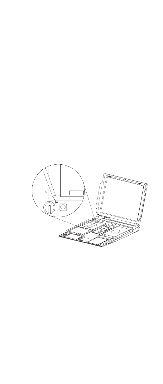
How to Disable the Password
There are three passwords used at a typical customer site:
the Supervisor Password, the hard disk drive password,
and the Power On password.
v Power On password:
1. Power off the computer.
2. Remove the battery pack and AC Adapter.
3. Remove the keyboard, see “1020 Keyboard ASM” on
page 31.
4. Short the jumper JP1. See the following figure:
JP1
5. Replace the keyboard.
6. Power on the computer and wait until POST ends.
7. Verify that the password prompt does not appear.
v Supervisor and hard disk drive passwords:
The Supervisor Password and hard disk drive password
are security features that are used to protect the system
and the hard disk drive data from unauthorized access.
No overriding capability is provided, so they cannot be
replaced if they are forgotten. If the customer forgets the
Supervisor Password, the system board must be
replaced. If the customer forgets the hard disk drive
password, the hard disk drive must be replaced.
ThinkPad s30, s31
3
Page 8

Product Overview
The following shows an overview of the system features of
the ThinkPad s30 and s31 series.
Feature Description
Processor Intel Mobile Pentium III 600 MHz, 128
Bus architecture PCI Bus
Memory 128 MB SDRAM onboard
BIOS ROM up to 512 Kbytes
Video
Audio
Hard disk drive s30
I/O ports
Internal Ethernet/modem 56 Kbps (depends on the model)
PC card (PCMCIA) One Type II
Mini-PCI card Mini-PCI Type-IIIa
AC Adapter 56–Watt type
KB L2 cache
32 MB, 64 MB or 128 MB DIMM card
(max. 256 MB)
v 10.4–inch, 16M colors, 640x480 or
1024x768 pixel TFT color LCD
v 20–bit stereo D/A and 18–bit stereo
A/D audio
v Internal stereo speakers
v 10/20 GB, 2.5–inch, IDE interface
s31
v 15/30 GB, 2.5–inch, IDE interface
v External monitor (mini-plug)
v Headphone/line-out
v Microphone-in
v USB
v RJ-11
v RJ-45
CardBus support
Fn Key Combinations
The following table shows the Fn key and function key
combinations and their corresponding functions.
The Fn key works independently of the operating system.
The operating system obtains the status through the
system management interface to control the system.
Fn + Result
F3 LCD off
4 ThinkPad s30, s31
Page 9
Fn + Result
F4 Suspend mode
F7 Switch between the LCD, the external monitor, and
F12 Hibernation mode
Insert Increases the volume
Delete Decreases the volume
Backspace Mutes the internal speaker
Home Increase brightness
End Decrease brightness
PgUp Toggle ThinkLight on/off
Spacebar
(s31 only)
both the LCD and external monitor.
Enables the FullScreen Magnifier
Note: Some models use the three volume control buttons
to adjust the volume. The volume control buttons
are located above the keyboard, next to the
ThinkPad button.
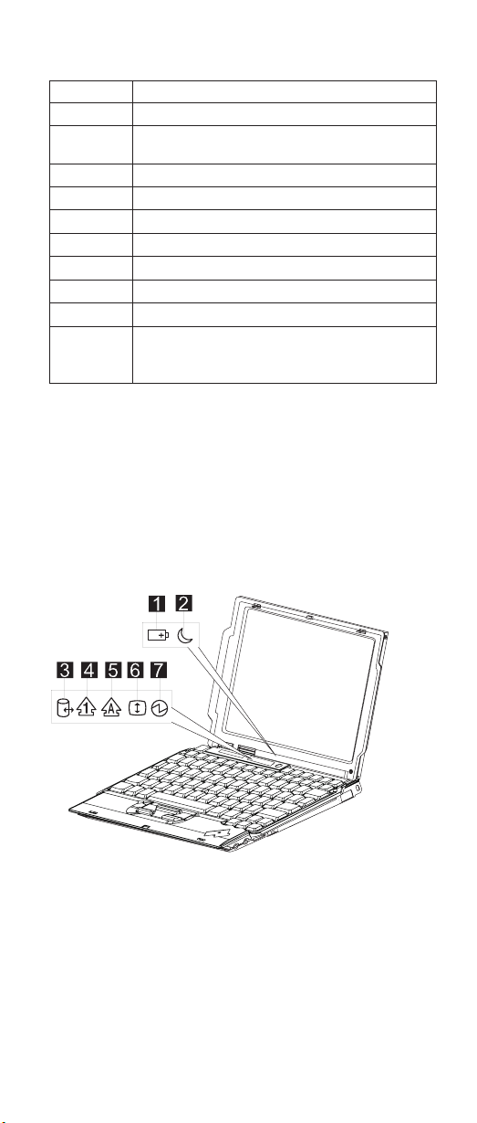
Status Indicators
The system status LED indicators show the current
computer status. The following shows the location of each
indicator symbol and the meaning of each indicator.
ThinkPad s30, s31 5
Page 10
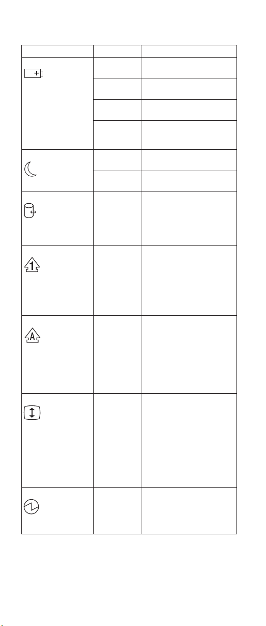
Symbol Color Meaning
(1) Battery status
(2) Suspend mode
(3) Drive in use
(4) Numeric lock
(5) Caps lock
(6) Scroll lock
(7) Power on
Green Enough battery power
Blinking
orange
Orange The battery pack is being
Blinking
green
Green The computer is in suspend
Blinking
green
Green Data is being read from or
Green The numeric keypad on the
Green Caps Lock mode is
Green Scroll Lock mode is
Green The computer is
remains for operation.
The battery pack needs to
be charged.
charged.
The battery pack is being
charged and is almost fully
charged.
mode.
The computer is entering
suspend mode.
written to the hard disk
drive. Do not enter
hibernation mode or power
off the computer when this
indicator is on.
keyboard is enabled. You
enable or disable the
keypad by pressing and
holding the Shift key, and
pressing the NumLk key.
For details, see the User’s
Reference.
enabled. All alphabetic
characters (A-Z) are
entered in capital letters
without the Shift key being
pressed. You enable or
disable the Caps Lock
mode by pressing the Caps
Lock key.
enabled. The Arrow keys
can be used as
screen-scroll function keys.
The cursor cannot be
moved with the Arrow
keys. Not all application
programs support this
function. You enable or
disable Scroll Lock mode by
pressing the ScrLk key.
operational. This indicator is
always on when the
computer is on or in
suspend mode.
6 ThinkPad s30, s31
Page 11

Related service information
This section provides information about restoring the
pre-installed software.
Restoring the pre-installed software
To restore the pre-installed software for the s30 you can
use either the Product Recovery Program or a Recovery
CD.
To restore the pre-installed software for the s31 you can
only use the Product Recovery Program.
The Product Recovery Program is in a section of the hard
disk drive (the Service Partition) that is not displayed by
Windows Explorer. Use the Recovery CD if it was provided
with the computer.
Note: The recovery process might take up to 2 hours.
To use the Product Recovery program to restore the
pre-installed software, do the following:
1. Save all files and shut down the desktop.
2. Turn off the computer.
3. Turn on the computer. Quickly press F11 when this
message is displayed on the screen: ...″To start the
Product Recovery Program, press F11″...This message
is displayed for only a few seconds.
Note: If this message does not appear, you can use a
Recovery Repair diskette to get access to the
Product Recovery program. (see “To create a
recovery repair diskette” on page 8 for
instructions of making the Recovery Repair
diskette).
4. From the list displayed on the screen, select the
operating system you want to recover.
5. Select the recovery options you want, and follow the
instructions on the screen.
Creating the service partition for the s30 series
To create the Service Partition and install the preloaded
system from the Recovery CD, do the following;
To create the Service Partition (SP):
1. Erase all partitions on the hard-disk drive using
FDISK or a similar application.
2. Boot with the Recovery CD (and the boot diskette if
required).
ThinkPad s30, s31
7
Page 12

3. A menu will appear stating ″Your computer originally
included a Product Recovery program...Reinstall the
Product Recovery Program? (Y/N)″.
Note: If the hard-disk drive contains any partitions,
you will not receive this menu-go to step 1.
4. Enter ″Y″ and the Service Partition will be created
and loaded with D2D files.
Note: If you do not want to create the Service
Partition, press ″N″, and then go to step 8.
5. Press Enter at the next window to continue.
The Service Partition is created. The system
automatically reboots during this process.
The recovery process copies some files to the Service
Partition and, PKUNZIPs others.
Follow the prompts-you may be prompted to change
CDs.
The system reboots when the process is complete.
Continue to step 6 to install the preloaded system.
Install the preloaded system from the CD.
6. Boot with the Recovery CD (and the boot diskette if
required).
7. If the hard disk drive is blank, a menu will appear
stating ″Your computer originally included a Product
Recovery program...Reinstall the Product Recovery
program? (Y/N)
To install the Service Partition, go to step 4.
To preload the hard disk drive without installing the
Service Partition, press ″N″.
8. If a menu appears asking which operating system to
install, highlight the proper operating system and
press ″ENTER″.
9. A menu will appear stating ″Full Recovery:″. Press
″ENTER″ to select.
10. Enter ″Y″ at the three windows which follow.
11. Follow the prompts to complete Recovery.
To create a recovery repair diskette
The Recovery Repair diskette is used to recover the
prompt that is needed to access the Product Recovery
program, if the prompt does not appear. Make a Recovery
Repair diskette and save it for future use. To make a
Recovery Repair diskette:
1. Shut down and restart the computer.
2. Attach the external diskette drive to the computer.
8 ThinkPad s30, s31
Page 13

3. At the prompt, press F11. (The option to press F11
appears for only a few seconds. You must press F11
quickly). The Product Recovery program main menu
appears.
4. If you are using Windows 2000 Professional, you will
be prompted to select the appropriate operating system
setting. This menu does not appear for Windows 98
SE.
5. Select System Utilities from the main menu. Press
Enter.
6. Select Create a Recovery Repair diskette. Press Enter.
7. Follow the on-screen instructions.
8. When the process is completed, label the diskette as
the Recovery Repair diskette and save it for future use.
To use the recovery repair diskette
1. Shut down and turn off the computer.
2. Attach the external diskette drive to the computer.
3. Insert the Recovery Repair diskette into the drive; then
turn on the computer.
4. Follow the on-screen instructions.
Checkout Guide
Use the following procedure as a guide for computer
problems.
Note: The diagnostic tests are intended to test only IBM
products. Non-IBM products, prototype cards, or
modified options can give false errors and invalid
system responses.
1. Obtain the failing symptoms in as much detail as
possible.
2. Verify the symptoms by attempting to recreate the
failure by running the diagnostic test or by repeating
the same operation.
Note: To run the diagnostics, refer to “Running the
Diagnostics” on page 27.
3. Use the following table with the verified symptom to
determine which page to go to. Search the symptoms
column and find the description that best matches your
symptom; then go to the page shown in the ″Go to″
column.
ThinkPad s30, s31
9
Page 14

Symptoms (Verified) Go to
Power failure. (The power-on
indicator does not go on or stay
on.)
POST does not complete. No
beeps or error codes/messages
are indicated.
POST beeps, but no error
codes are displayed.
POST detected an error and
displayed numeric error codes.
The diagnostic test detected an
error and displayed a FRU
code.
Other symptoms (such as LCD
display problems).
Symptoms cannot be recreated
(intermittent problems).
“Power System Checkout” on
page 14, then use table in
“Power-Related Symptoms” on
page 23.
“Symptom-to-FRU Index” on
page 19, then use table in “No
Beep Symptoms” on page 22.
“Symptom-to-FRU Index” on
page 19.
“Symptom-to-FRU Index” on
page 19, then use table in
“Numeric Error Codes” on
page 19.
“Running the Diagnostics” on
page 27.
“Symptom-to-FRU Index” on
page 19.
Use the customer-reported
symptoms, and go to
“Symptom-to-FRU Index” on
page 19.
Testing the computer
The ThinkPad computer has a test program called
PC-Doctor for DOS (hereafter called PC-Doctor). You can
detect errors by running the diagnostics test of PC-Doctor.
This section is an overview on detecting the problem.
To run the test, do the following:
Note: In the following procedure, you can select an item
not only with the arrow keys, but also with the
TrackPoint. Instead of pressing Enter, you can also
click the left click button.
1. Connect the USB diskette drive to the computer.
2. Insert the PC-Doctor DOS Disk into the diskette drive;
then power on the computer.
If the computer cannot be powered on, go to “Power
System Checkout” on page 14 and check the power
sources.
If an error code appears, go to “Symptom-to-FRU
Index” on page 19.
The PC-Doctor main panel appears.
3. Select Diagnostics with the arrow keys, and press
Enter.
A pull-down menu appears:
10 ThinkPad s30, s31
Page 15

Note: The pull-down menu differs depending on the
model.
4. Run the applicable function test.
5. Follow the instructions on the screen. If there is a
problem, PC-Doctor shows some messages.
6. Reseat the cable or connector of the detected FRU
and run the test again.
If the error recurs, replace the FRU that caused the
error.
Note: With some FRUs, especially the system board,
the problem may be caused by peripheral
FRUs. Verify that each peripheral FRU, such as
the flexible cable, has no problem by doing the
following:
a. Replace each peripheral FRU one at a time,
and run the test again.
b. If the peripheral FRUs have no problem,
replace the main FRU itself.
7. To exit the test, select Quit – Exit Diag.
To cancel the test, press Esc.
The following table lists the options on the test menu.
Diagnostics Interactive Tests
v Run Normal Test
v Run Quick Test
v CPU/Coprocessor
v Systemboard
v Video Adapter
v Fixed Disks
v Diskette Drives
v Other Devices
v Memory Test – Full
v Memory Test – Quick
Note: In Keyboard test within Interactive Tests, the Fn key is
scanned only once. Each key should be pressed for at least 2
seconds; otherwise, it cannot be sensed.
v Keyboard
v Video
v Internal Speaker
v Mouse
v Joystick Test
v Diskette Test
v System Load
v Stereo Speaker
Note: (s30 only) The testing of 802.11b requires an
Access Point properly prepared prior to conducting
the test. When testing 802.11b with PC-Doctor
DOS, please confirm the following points:
1. An OBI’s Access Point is located about 3 meters
from the system.
2. The encryption is disabled on the Access Point.
ThinkPad s30, s31
11
Page 16

If the distance between the Access Point and the
system is too far, the test may report failure even if
the device is properly working. If the encryption is
enabled on the Access Point, the test program
cannot properly communicate with the Access Point
to test the device, and will report failure.
Due to the nature of wireless connection, the test
may report failure with ″No LinkTest response
received″ error message in the log, even if the
device is working properly. When the test failed with
this error, please repeat the test for a few times.
The device may be working properly unless the
same error persists.
Audio Checkout
Do as follows:
1. Boot from the diagnostics diskette and start the
program.
2. Go to Interactive Tests on the main menu and select
the Internal Speakers test.
3. If no sound is heard, replace the speakers.
Fan ASM Checkout
To check the fan ASM, do the following:
1. Boot from the diagnostics diskette and start the
program.
2. Go to Diagnostics on the main menu and select Other
Devices.
3. Follow the description in the window. If the test detects
a fan ASM problem, replace the fan.
Keyboard and Auxiliary Input Device Checkout
Note: Remove the external keyboard if the internal
keyboard is to be tested.
If the internal keyboard does not work or an unexpected
character appears, make sure that the flexible cable
extending from the keyboard is correctly seated on the
connector.
If the keyboard cable connection is correct, run the
Keyboard Test. See “Running the Diagnostics” on page 27
for details.
If the test detects a keyboard problem, do the following
one at a time to correct the problem. Do not replace a
non-defective FRU.
12 ThinkPad s30, s31
Page 17

1. Replace the keyboard.
2. Replace the system board.
The following auxiliary input devices are supported for this
computer:
v Numeric keypad
v Mouse (USB-compatible)
v External keyboard (USB-compatible)
If any of these devices do not work, reseat the cable
connector and repeat the failing operation.
If the problem does not reoccur, replace the device and
then the system board.
Memory Checkout
DIMM are available for increasing memory capacity.
Onboard (MB) Slot (MB) Total Memory (MB)
128 0 128
128 32 160
128 64 192
128 128 256
Memory errors might stop system operation, show error
messages on the screen, or hang the system.
Use the following procedure to isolate memory problems:
1. Turn off the computer and remove any installed DIMM
from its slot.
2. Boot from the diagnostics diskette and start the
program.
3. Go to Diagnostics on the main menu and select
Memory Test. If an error appears, replace the system
board.
4. Turn off the computer and reinstall the DIMM; then turn
on the computer. Verify the memory size; then test the
memory. If an error appears, replace the DIMM.
Note: Make sure that the DIMM is properly installed into
the connector. A loose connection can cause an
error.
1394/LAN or Wireless Board Checkout (s30 only)
Do the following to isolate the problem to the system
internal 1394/LAN or wireless board:
ThinkPad s30, s31
13
Page 18
1. Boot from the diagnostics diskette and start the
program.
2. Go to Diagnostics on the main menu and select Other
Devices.
3. Follow the description in the window.
4. If the test detects a problem, replace the board.
Power System Checkout
To verify the symptom of the problem power on the
computer using each of the following power sources:
1. Remove the battery ASM.
2. Connect the AC Adapter and check that power is
supplied.
3. Disconnect the AC Adapter and install the charged
battery ASM; then check that power is supplied by the
battery ASM.
If you suspect a power problem, refer to the appropriate
power supply check listed below:
v “Checking the AC Adapter”
v “Checking the Operational Charging” on page 15
v “Checking the Battery ASM” on page 15
Checking the AC Adapter
You are here because the computer fails only when the AC
Adapter is used:
v If the power-on indicator does not turn on, check the
power cord of the AC Adapter for correct continuity and
installation.
v If the operational charge does not work, go to “Checking
the Operational Charging” on page 15.
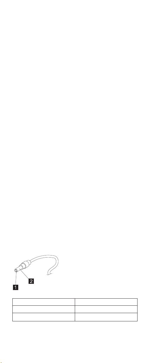
Unplug the AC Adapter cable from the computer and
measure the output voltage at the plug of the AC Adapter
cable. See the following figure.
Pin Voltage (V dc)
1 +15.5 to +17.0
2 Ground
If the voltage is not correct, replace the AC Adapter.
14 ThinkPad s30, s31
Page 19
If the voltage is within the range, do the following:
v Replace the system board.
v If the problem is not corrected, go to “Undetermined
Problems” on page 25.
Note: An audible noise from the AC Adapter does not
always indicate a defective adapter.
Checking the Operational Charging
To check operational charging, use a discharged battery
pack (battery ASM) or a battery ASM that has less than
50% of the total power remaining when installed in the
computer.
Perform operational charging. If the battery status indicator
does not turn on, remove the battery ASM and let it return
to room temperature. Reinstall the battery ASM.
If the charge indicator still does not turn on, replace the
battery ASM. If the charge indicator still does not turn on,
replace the system board. Then reinstall the battery ASM.
If the reinstalled battery ASM is not charged, go to the next
section.
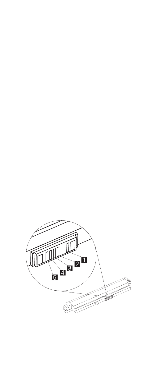
Checking the Battery ASM
Do the following:
1. Power off the computer.
2. Remove the battery ASM and measure the voltage
between battery terminals 1 (+) and 5 (-). See the
following figure:
Note: Signal lines, not used in these steps, are used
for communications between the system and the
battery.
ThinkPad s30, s31
15
Page 20

3. If the voltage is less than 10.6V, the battery ASM has
been discharged, recharge the battery ASM. If the
voltage is still less than 10.6V, replace the battery.
TrackPoint Checkout
If the external mouse is connected, the TrackPoint does
not work. In this case, please detach the external mouse to
check the TrackPoint.
If this does not correct the TrackPoint problem, continue
with the following:
After you use the TrackPoint, the pointer drifts on the
screen for a short time. This self-acting pointer movement
can occur when a slight, steady pressure is applied to the
TrackPoint pointer. This symptom is not a hardware
problem. No service actions are necessary if the pointer
movement stops in a short period of time.
If a click button problem or pointing stick problem occurs,
do the following:
1. Boot from the diagnostics diskette and start the
program.
2. Go to Interactive Tests on the main menu and select
Mouse.
3. Follow the instructions in the message window.
If either the pointing stick or the click button does not work,
do the following actions one at a time to correct the
problem. Do not replace a non-defective FRU.
1. Reseat the keyboard Touchbutton cables.
2. Replace the keyboard.
3. Replace the system board.
Power Management Features
Three power management modes are available in the
computer system to reduce power consumption and to
prolong battery life.
Standby Mode
In standby mode, the following occurs:
v The LCD backlight turns off.
v The hard disk drive motor stops.
Events that cause the computer to enter standby mode:
v Standby mode requested by the Fn key (Fn+F4).
The computer exits standby and resumes operation when
any key is pressed.
16 ThinkPad s30, s31
Page 21

Suspend Mode
In suspend mode, the following occurs:
v The LCD is powered off.
v The hard disk drive is powered off.
v The CPU stops.
Events that cause the computer to enter suspend mode:
v Suspend mode requested by the Fn key (Fn+F4).
v The Lid is closed.
v The specified time has elapsed.
v Battery low occurs and hibernation conditions are
insufficient.
Note: When battery is low, the battery status indicator
blinks orange.
Note: In the IBM BIOS Setup Utility, the computer can be
set to suspend when the lid is closed.
The following events cause the computer to resume
operation from suspend mode:
v The Lid is opened.
v The real time clock alarm is signaled.
v The ring indicator (RI) is signaled by a PC Card device
or the internal modem.
v The Fn key is pressed.
v Power switch is pressed.
The computer also exits suspend mode when the battery is
critically low or timer conditions are satisfied for entering
hibernation mode.
Hibernation Mode
Note: Before using hibernation mode, you need a
hibernation file.
In hibernation mode, the following occurs:
v The system status, RAM, VRAM, and setup data are
stored on the hard disk.
v The system is powered off.
Events that cause the computer to enter hibernation mode:
v Hibernation mode requested by function key (Fn+F12).
v Timer conditions are satisfied in suspend mode when
hibernate by timer is enabled.
v A critically low battery condition occurs.
v The power switch is pressed. (BIOS Setup)
ThinkPad s30, s31
17
Page 22

The computer exits hibernation mode and resumes
operation when the power-on switch is pressed. When
power is turned on, the hibernation file in the boot record
on the hard disk drive is read and the system status is
restored from the hard disk drive.
The power switch must be pressed to cause the computer
to resume operation from hibernation mode.
How to Create the Hibernation Function: Do as
follows:
v Turn off the computer.
v Connect the USB diskette drive to the computer.
v Insert the hibernation utility diskette into the diskette
drive (you can create the diskette using the Diskette
Factory).
v Turn on the computer.
v Follow the instructions on the screen.
Note: If you change the memory size, you need to
recreate the hibernation file or partition. For
partition-based hibernation, use the hibernation
utility to delete the partition first before creating a
new one.
18 ThinkPad s30, s31
Page 23

Symptom-to-FRU Index
The Symptom-to-FRU Index lists the symptoms and errors
and the possible causes. The most likely cause is listed
first.
Note: Perform the FRU replacement or actions in the
sequence shown in the FRU/Action columns. If a
FRU replacement does not solve the problem, put
the original part back in the computer. Do not
replace a non-defective FRU.
This index can also be used to help you decide the next
possible FRUs to be replaced when servicing a computer.
Numeric error codes show the errors detected in POST or
system operation (runtime). In the following error codes, X
can be any number. If no codes are available, use
narrative symptoms.
If the symptom is not listed, go to “Undetermined
Problems” on page 25.
Note: For IBM devices not supported by diagnostic codes
in this ThinkPad computer, see the manual for that
device.
Numeric Error Codes
The following is a list of the message that the BIOS can
display. Most of them occur during POST. Some of them
display information about a hardware device, e.g., the
amount of memory installed. Others may indicate a
problem with a device, such as the way it has been
configured. Following the list are explanations of the
messages and remedies for reported problems.
If the system fails after you make changes in the Setup
menus, reset the computer, enter Setup and install Setup
defaults or correct the error.
Symptom/Error FRU/Action in Sequence
0200
Failure Fixed Disk
0210
Keyboard error
1. Reseat hard disk drive.
2. Load Setup Defaults in BIOS Setup
Utility.
3. Hard disk drive
4. System board
Go to “Keyboard and Auxiliary Input Device
Checkout” on page 12.
ThinkPad s30, s31 19
Page 24

Symptom/Error FRU/Action in Sequence
0212
Keyboard
Controller Failed
0213
Keyboard locked
— Unlock key
switch
0220
Monitor type does
not match CMOS
— Run Setup
0230
Shadow RAM
Failed at
offset:nnnn
0231
System RAM
Failed at
offset:nnnn
0232
Extended RAM
Failed at
offset:nnnn
0250
System battery is
dead
0251
System CMOS
checksum bad —
Default
configuration used
0260
System timer error
0270
Real time clock
error
0280
Previous boot
incomplete —
Default
configuration used
Go to “Keyboard and Auxiliary Input Device
Checkout” on page 12.
Unlock external keyboard.
Load Setup Defaults in BIOS Setup Utility.
System board
1. DIMM
2. System board
1. DIMM
2. System board
System board
System board
1. Run BIOS Setup Utility to reconfigure the
system, then reboot the system.
2. System board
1. Run BIOS Setup Utility to reconfigure the
system, then reboot the system.
2. System board
1. Load Setup Defaults in the BIOS Setup
Utility.
2. System board
20 ThinkPad s30, s31
Page 25

Symptom/Error FRU/Action in Sequence
0281
Memory size
found by POST
differed from
CMOS
02D0
System cache
error — Cache
disabled
02F0
CPU ID:
02F5
DMA Test Failed
02F6
Software NMI
Failed
02F7
Fail-Safe Timer
NMI Failed
1. Load Setup Defaults in the BIOS Setup
Utility.
2. DIMM
3. System board
System board
System board
1. DIMM
2. System board
1. DIMM
2. System board
1. DIMM
2. System board
Error Messages
Symptom/Error FRU/Action in Sequence
Device Address
Conflict
Allocation Error
for: device
Failing Bits: nnnn
Invalid System
Configuration
Data
I/O device IRQ
conflict
1. Load Setup Defaults in BIOS Setup
Utility.
2. System board
1. Load Setup Defaults in BIOS Setup
Utility.
2. System board
1. DIMM
2. System board
System board
1. Load Setup Defaults in BIOS Setup
Utility.
2. System board
ThinkPad s30, s31 21
Page 26

Symptom/Error FRU/Action in Sequence
Operating system
not found
1. Check that the operating system has no
failure and is installed correctly.
2. Enter IBM BIOS Setup Utility and see
whether the hard disk drive and the
diskette drive are properly installed.
3. Diskette drive
4. Hard disk drive
5. System board
No Beep Symptoms
Symptom/Error FRU/Action in Sequence
No beep, power-on
indicator on, LCD blank,
no POST
No beep, power-on
indicator off, LCD blank
during POST
No beep, power-on
indicator on, LCD blank
during POST
No beep during POST
but system runs correctly.
1. Ensure every connector is
connected tightly and correctly.
2. DIMM
3. System board
1. Battery ASM
2. AC Adapter
3. System board
1. Reseat DIMM.
2. System board
Speaker
LCD-Related Symptoms
Symptom/Error FRU/Action in Sequence
LCD backlight not
working
LCD too dark
LCD brightness cannot
be adjusted
LCD screen unreadable
Character missing pels
Screen abnormal
Wrong color displayed
LCD has extra horizontal
or vertical lines
displayed.
22 ThinkPad s30, s31
1. Reseat the LCD connector.
2. LCD FPC ASM
3. LCD inverter
4. LCD
5. System board
1. Reseat the LCD connector.
2. LCD FPC ASM
3. LCD inverter
4. LCD
5. System board
1. LCD FPC ASM
2. LCD inverter
3. LCD
4. System board
Page 27

Keyboard-Related Symptoms
Symptom/Error FRU/Action in Sequence
Keyboard (one or more
keys) doesn’t work.
1. Reseat the keyboard cable.
2. Keyboard
3. System board
Indicator-Related Symptoms
Symptom/Error FRU/Action in Sequence
Indicator incorrectly
remains off or on, but
system runs correctly.
1. Reseat the keyboard connector.
2. Reseat the LCD-to-system-board
connector.
3. System board
Power-Related Symptoms
Symptom/Error FRU/Action in Sequence
Power shuts down during
operation.
The system will not
power on.
The system will not
power off.
Battery can’t be charged.
1. Battery
2. AC Adapter
3. System board
1. Battery ASM
2. AC Adapter
3. System board
System board
1. Battery
2. System board
PC Card (PCMCIA)-Related Symptoms
Symptom/Error FRU/Action in Sequence
System cannot detect the
PC Card (PCMCIA)
1. PC Card (PCMCIA) slots
assembly
2. System board
CompactFlash Card-Related Symptoms
Symptom/Error FRU/Action in Sequence
System cannot detect the
CompactFlash Card
System board
ThinkPad s30, s31 23
Page 28

Speaker-Related Symptoms
Symptom/Error FRU/Action in Sequence
Speakers make noise or
no sound comes from
system.
In DOS or Windows
multimedia programs, no
sound comes from the
computer.
1. Speakers
2. System board
1. Speakers
2. System board
Power Management-Related Symptoms
Symptom/Error FRU/Action in Sequence
The system will not enter
hibernation mode.
The system will not wake
up from hibernation
mode.
The system will not enter
suspend mode after
closing the LCD.
Battery fuel-gauge does
not go higher than 90%.
System configuration
does not match the
installed devices.
System hangs
intermittently.
1. Keyboard (if control is from the
keyboard)
2. Hard disk drive
3. System board
1. Keyboard (if control is from the
keyboard)
2. Hard disk drive
3. System board
1. Reseat suspend board cable
2. Suspend board ASM
3. System board
1. Remove battery ASM and let it
cool for 2 hours.
2. Refresh battery (continue using
battery in BIOS Setup mode until
power off, then charge battery).
3. Battery
4. System board
Load Setup Defaults and reboot the
system.
1. Fan ASM
2. System board
Peripheral-Device-Related Symptom
Symptom/Error FRU/Action in Sequence
External display does not
work correctly.
USB does not work
correctly.
24 ThinkPad s30, s31
1. CRT adapter
2. System board
1. Power board ASM
2. System board
Page 29

Symptom/Error FRU/Action in Sequence
IEEE 1394 does not work
correctly
Modem does not work
correctly
Ethernet does not work
correctly
Wireless LAN does not
work correctly (s30 only)
Print problems
1. IEEE 1394 cable
2. Card-to-system board cable
3. IEEE 1394/LAN card ASM
4. System board
1. Modem cable
2. Modem card ASM
3. System board
1. Card-to-system board cable
2. LAN/1394 combo card ASM
3. Base cover ASM
4. System board
1. Wireless card ASM
2. System board
1. Run printer self-test.
2. Printer driver
3. Printer cable
4. System board
Note: If you cannot find a symptom or an error in this list
and the problem remains, see “Undetermined
Problems”.
Intermittent Problems
Intermittent system hang problems can be caused by a
variety of reasons that have nothing to do with a hardware
defect, such as cosmic radiation, electronic discharge, or
software errors. FRU replacement should be considered
only when a recurring problem exists.
When analyzing an intermittent problem, do the following:
1. Run the diagnostic test for the system board in loop
mode at least 10 times.
2. If no error is detected, do not replace any FRUs.
3. If any error is detected, replace the FRU shown by the
FRU code. Rerun the test to verify that no more errors
exist.
Undetermined Problems
You are here because the diagnostic tests did not identify
which adapter or device failed, which installed devices are
incorrect, whether a short circuit is suspected, or whether
the system is inoperative. Follow these procedures to
isolate the failing FRU (do not isolate non-defective FRUs).
ThinkPad s30, s31
25
Page 30

Verify that the power supply being used at the time of the
failure is operating correctly. (See “Power System
Checkout” on page 14.)
1. Power off the computer.
2. Visually check for damage. If any problems are found,
replace the FRU.
3. Remove or disconnect all of the following devices:
a. Non-IBM devices
b. Printer, mouse, and other external devices
c. Battery ASM
d. Hard disk drive
e. DIMM
f. PC Cards (PCMCIA)
4. Power on the computer.
5. Determine if the problem has changed.
6. If the problem does not recur, reconnect the removed
devices one at a time until you find the failing FRU.
7. If the problem remains, replace the following FRUs one
at a time. Do not replace a non-defective FRU.
a. System board
b. LCD panel ASM
26 ThinkPad s30, s31
Page 31

CE Utility Program Diskette
Writing the Serialization Information
The EEPROM on the system board contains the
Serialization Information Data— that is, a system board
serial number and a system unit serial number. When you
replace the system board, restore the Serialization
Information Data using the ThinkPad CE Utility Diskette.
The serial number label is attached to the computer.
Writing the UUID
The EEPROM on the system board contains the Universal
Unique ID (UUID)— that is, for Microsoft or Internet use.
When you replace the system board, restore the new
UUID using the ThinkPad CE Utility Diskette. The
ThinkPad Utility will automatically generate and assign the
new UUID.
Running the Diagnostics
Use either the TrackPoint or the cursor move keys to
interact with the tests.
1. Connect the external floppy disk drive to the computer.
2. Insert the PC-Doctor startup disk into the diskette drive.
3. Power-on the computer.
4. At the main menu, select the test to run.
5. Press Enter to run the test selected.
6. After starting a test, do not press any key until
prompted, then follow the instructions on the screen.
7. When the test is completed, press Esc to return to the
main menu.
8. Select Quit/Exit Diags to exit the diagnostics utility.
ThinkPad s30, s31
27
Page 32

FRU Removals and Replacements
This section contains information about removals and
replacements.
v Do not damage any parts. Only certified and trained
personnel should service the computer.
v The arrows in this section show the direction of
movement to remove a FRU, or to turn a screw to
release the FRU. The arrows are marked in numeric
order, in square callouts, to show the correct sequence
of removal.
v When other FRUs must be removed before the failing
FRU is removed, they are listed at the top of the page.
v To replace a FRU, reverse the removal procedure and
follow any notes that pertain to replacement.
v When replacing a FRU, use the correct screw size, as
shown in the procedures.
Safety Notice 1::
Before the computer is powered on after FRU
replacement, make sure all screws, springs, or other small
parts, are in place and are not left loose inside the
computer. Verify this by shaking the computer and listening
for rattling sounds. Metallic parts or metal flakes can cause
an electrical short circuit.
Safety Notice 4::
The battery can cause a fire, explosion, or severe burn. Do
not recharge it, remove its polarized connector,
disassemble it, heat it above 100°C (212°F), incinerate it,
or expose its cell contents to water. Dispose of the battery
as required by local ordinances or regulations. Use only
the battery in the appropriate parts listing. Use of an
incorrect battery can result in ignition or explosion of the
battery.
Safety Notice 8::
Before removing any FRU, power-off the computer, unplug
all power cords from electrical outlets, remove the battery
ASM, and then disconnect any interconnecting cables.
An electrostatic discharge (ESD) strap (P/N 6405959) must
be used to establish personal grounding.
FRU Service Procedures
Review the following procedures before replacing any
FRU.
28 ThinkPad s30, s31
Page 33

LCD FRU Replacement Notice
The TFT LCD (XGA 10.4–inch) for the computer contains
many thin-film transistors (TFTs). A small number of
missing, discolored, or lighted dots (on all the time) is
characteristic of TFT LCD technology, but excessive pixel
problems can cause viewing concerns. The LCD should be
replaced if the number of missing, discolored, or lighted
dots in any background is: 5 or more bright dots, 5 or more
dark dots, or a total of 9 or more bright and dark dots.
Replacing the System Board
When you replace the system board, restore the computer
Serialization Information Data and reassign the UUID using
the ThinkPad CE Utility Diskette.
Note: Do not power off the computer while restoring the
Serialization Information Data and the UUID.
Important Notice
This computer uses special nylon-coated screws
with the following characteristics:
v They maintain tight connections.
v They do not easily come loose, even with shock
or vibration.
v They need additional force to tighten.
v They should be used only once.
Do the following when you service this computer:
v Have a screw kit (10L1956) available.
v Always use new screws if you are instructed.
v Use a torque screwdriver (U.S. only) if you have
one.
ThinkPad s30, s31 29
Page 34

1010 Battery ASM
To remove the battery ASM:
1. Slide the release latch as shown.
2. Remove the battery ASM.
Reverse the steps described above when installing a new
battery pack.
30 ThinkPad s30, s31
Page 35

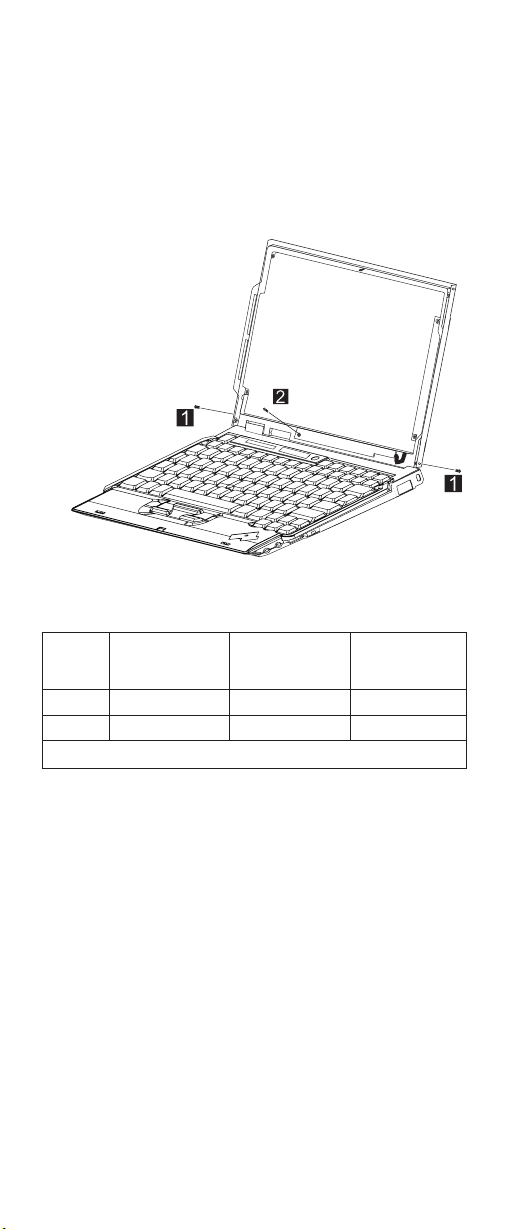
1020 Keyboard ASM
v 1010 Battery ASM
To remove the keyboard ASM:
1. Remove the four screws securing the keyboard.
2. Loosen the other three screws: these screws are fixed
to the computer.
3. Turn the notebook over; then move the keyboard as
shown.
4. Disconnect the keyboard connector from the system
board and remove the keyboard.
Size
Step
1 M2.0 x 7L (4) Flat head, black 2.5 kgf-cm
2 N/A N/A 2.0 kgf-cm
Note: Make sure you use the correct screw for replacement.
(Quantity) Head & Color Torque
ThinkPad s30, s31 31
Page 36

1030 Hard Disk Drive ASM
v 1010 Battery ASM
v 1020 Keyboard ASM
Warning:
v Do not drop or apply any shock to the hard disk drive.
The hard disk drive is sensitive to physical shock.
Incorrect handling can cause damage and permanent
loss of data on the drive.
v Before removing the drive, have the user make a
backup copy of all the information on the drive if
possible.
v Never remove the drive while the system is operating or
is in suspend mode.
For the s30 series
To remove the hard disk drive ASM:
1. Slide and lift the drive bracket as shown to remove the
bracket.
32 ThinkPad s30, s31
Page 37
2. Disconnect the IDE connector from the system board
and remove the hard disk drive.
For the s31 series
To remove the hard disk drive ASM:
1. Slide and lift the drive bracket as shown to remove the
bracket.
2. Remove the screw from the HDD/FPC bracket.
ThinkPad s30, s31
33
Page 38

3. Remove the HDD/FPC bracket.
4. Disconnect the IDE connector from the system board
and remove the hard disk drive.
Size
Step
2 M2.0 x 4L (1) Flat head, black 2.0 kgf-cm
Note: Make sure you use the correct screw for replacement.
(Quantity) Head & Color Torque
34 ThinkPad s30, s31
Page 39

1035 Hard Disk Drive FPC ASM
v 1010 Battery ASM
v 1020 Keyboard ASM
v 1030 Hard Disk Drive ASM
Warning:
v Do not drop or apply any shock to the hard disk drive.
The hard disk drive is sensitive to physical shock.
Incorrect handling can cause damage and permanent
loss of data on the drive.
v Before removing the drive or the FPC ASM, have the
user make a backup copy of all the information on the
drive if possible.
v Never remove the drive while the system is operating or
is in suspend mode.
To remove the hard disk drive FPC ASM:
v Grip the plastic strap as shown and remove the FPC
ASM.
ThinkPad s30, s31 35
Page 40

1040 Suspend Board ASM
v 1010 Battery ASM
v 1020 Keyboard ASM
To remove the suspend board:
1. Disconnect the cable from the suspend board.
2. Remove the two screws.
3. Remove the suspend board.
Size
Step
2 M2.0 x 4L (2) Flat head, black 2.0 kgf-cm
Note: Make sure you use the correct screw for replacement.
(Quantity) Head & Color Torque
36 ThinkPad s30, s31
Page 41

1045 Suspend Board Cable ASM
v 1010 Battery ASM
v 1020 Keyboard ASM
v 1040 Suspend Board ASM
To remove the suspend board cable ASM:
v Disconnect the suspend board cable from the system
board.
ThinkPad s30, s31 37
Page 42

1050 Modem Card ASM
v 1010 Battery ASM
v 1020 Keyboard ASM
To remove the modem card ASM:
1. Remove the two screws.
2. Lift the modem card to disconnect it from the system
board.
3. Disconnect the cable from the modem card.
Size
Step
1 M2.0 x 4L (2) Flat head, black 2.0 kgf-cm
Note: Make sure you use the correct screw for replacement.
(Quantity) Head & Color Torque
38 ThinkPad s30, s31
Page 43

1055 Modem Cable ASM
v 1010 Battery ASM
v 1020 Keyboard ASM
v 1050 Modem Card ASM
To remove the modem cable ASM:
v Disconnect the modem cable from the system board.
ThinkPad s30, s31 39
Page 44

1060 Wireless Card ASM (s30 only)
v 1010 Battery ASM
v 1020 Keyboard ASM
Warning:
Special care must be taken when disconnecting the
antenna cables from the wireless card not to damage the
connectors or cables. To replace either antenna cable, the
hinge ASM must be replaced.
Do not touch the antenna cables. Doing so can impair
antenna performance.
To remove the wireless card ASM:
1. Gently disconnect the two cables from the wireless
card.
2. Carefully release the latches on both sides of the
wireless card.
3. Remove the wireless card.
40 ThinkPad s30, s31
Page 45

1065 IEEE 1394/LAN Card ASM
v 1010 Battery ASM
v 1020 Keyboard ASM
To remove the IEEE 1394/LAN card ASM:
1. Disconnect the IEE 1394 cable from the card.
2. Disconnect the LAN cable from the card.
3. Disconnect the card-to-system board cable from the
card.
4. Carefully release the latches on both sides of the card.
5. Remove the IEEE 1394 card.
ThinkPad s30, s31
41
Page 46

1070 IEEE 1394/LAN Card Cable ASM
v 1010 Battery ASM
v 1020 Keyboard ASM
v 1065 IEEE 1394/LAN Card ASM
v 1040 Suspend Board ASM
To remove the IEEE 1394/LAN card cable ASM:
1. Remove the tape from the IEE 1394 cable.
2. Disconnect the IEE 1394 cable from the system board,
then remove the cable.
3. Disconnect the card-to-system board cable from the
system board, then remove the cable.
42 ThinkPad s30, s31
Page 47

1075 DIMM Card ASM
v 1010 Battery ASM
v 1020 Keyboard ASM
To remove the memory card ASM:
1. Carefully release the latches on both sides of the
memory card.
2. Gently remove the memory card.
ThinkPad s30, s31
43
Page 48

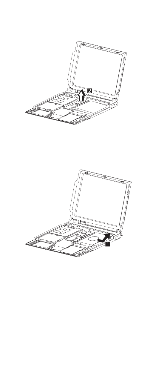
1080 Upper Cover ASM
v 1010 Battery ASM
v 1020 Keyboard ASM
To remove the upper cover ASM:
1. Remove the two screws.
A
2. Turn the computer over, then remove the upper cover
assembly as shown.
Size
Step
1 M2.5 x 5L (1) Flat head, black 2.5 kgf-cm
1A M2.0 x 4L (1) Flat head, black 2.5 kgf-cm
Note: Make sure you use the correct screw for replacement.
(Quantity) Head & Color Torque
44 ThinkPad s30, s31
Page 49

1085 Speaker ASM
v 1010 Battery ASM
v 1020 Keyboard ASM
To remove the speakers ASM:
1. Remove the connector.
2. Remove the four screws securing the speakers and
remove the speakers.
Size
Step
2 M2.0 x 4L (4) Flat head, black 2.0 kgf-cm
Note: Make sure you use the correct screw for replacement.
(Quantity) Head & Color Torque
ThinkPad s30, s31 45
Page 50

1090 Palm Rest ASM
v 1010 Battery ASM
v 1020 Keyboard ASM
v 1085 Speaker ASM
To remove the palm rest ASM:
1. Remove the three screws.
2. Remove the palm rest as shown.
Size
Step
1 M2.0 x 2.5L (3) Flat head, silver 2.0 kgf-cm
Note: Make sure you use the correct screw for replacement.
(Quantity) Head & Color Torque
46 ThinkPad s30, s31
Page 51

1100 Fan ASM
v 1010 Battery ASM
v 1020 Keyboard ASM
Warning:
Do not apply pressure on the fan blades or hub assembly;
doing so can damage the fan bearings.
To remove the fan ASM:
1. Remove the four screws securing the fan ASM.
2. Carefully lift the fan ASM.
A
Warning:
The fan ASM FRU includes a small pad of thermal rubber.
The thermal rubber has adhesive and protective paper on
both sides and must be fixed onto the fan ASM before
reassembly.
To fix the thermal rubber onto the fan ASM:
1. Remove the protective paper from one side of the
thermal rubber.
2. Press the thermal rubber firmly in place on the fan
ASM.
3. Remove the protective paper from the other side of the
thermal rubber.
ThinkPad s30, s31
47
Page 52

Protective paper
Size
Step
1 M2.0 x 7L (3) Flat head, black 2.5 kgf-cm
1A M2.0 x 9L (1) Flat head, black 2.0 kgf-cm
Note: Make sure you use the correct screw for replacement.
(Quantity) Head & Color Torque
Thermal rubber
48 ThinkPad s30, s31
Page 53

1130 PCMCIA Slots
v 1010 Battery ASM
v 1020 Keyboard ASM
v 1100 Fan ASM
Warning:
Special care must be taken when disconnecting the
PCMCIA slots not to cause a short or damage the
connector.
To remove the PCMCIA slots ASM:
1. Remove the three screws.
A
Note: The following steps 2 and 3 only apply to the
s31 series. If you are servicing the s30 series,
skiptostep4.
2. Remove the screw from the HDD/FPC bracket.
ThinkPad s30, s31
49
Page 54

3. Remove the HDD/FPC bracket.
4. Disconnect the FPC connector from the system board.
5. Grip firmly at the sides of the PCMCIA slots, then lift up
to remove.
Size
Step
1 M2.0 x 7L (2) Flat head, black 2.5 kgf-cm
1A M2.0 x 4L (1) Flat head, black 2.0 kgf-cm
2 M2.0 x 4L (1) Flat head, black 2.0 kgf-cm
Note: Make sure you use the correct screw for replacement.
(Quantity) Head & Color Torque
50 ThinkPad s30, s31
Page 55

1140 System Board
v 1010 Battery ASM
v 1020 Keyboard ASM
v 1030 Hard Disk Drive ASM
v 1040 Suspend Board ASM
v 1045 Suspend Board Cable ASM
v 1050 Modem Card ASM
v 1055 Modem Cable ASM
v 1060 Wireless Card ASM (s30 only)
v 1065 IEEE 1394/LAN Card ASM
v 1070 IEEE 1394/LAN Card Cable ASM
v 1075 DIMM Card ASM
v 1100 Fan ASM
v 1130 PCMCIA Slots
Note: See “CE Utility Program Diskette” on page 27 and
“Replacing the System Board” on page 29 before
proceeding.
To remove the system board ASM:
1. Remove the screw.
2. Disconnect the FPC connector from the system board.
3. Remove the system board.
Size
Step
1 M2.0 x 4L (1) Flat head, black 2.0 kgf-cm
Note: Make sure you use the correct screw for replacement.
(Quantity) Head & Color Torque
ThinkPad s30, s31 51
Page 56

1145 Power Board ASM
v 1010 Battery ASM
v 1020 Keyboard ASM
v 1030 Hard Disk Drive ASM
v 1040 Suspend Board ASM
v 1050 Modem Card ASM
v 1060 Wireless Card ASM (s30 only)
v 1100 Fan ASM
v 1130 PCMCIA Slots
v 1140 System Board
To remove the power board ASM:
1. Remove the two screws.
2. Remove the power board.
Size
Step
1 M2.0 x 2.5L (2) Flat head, silver 2.0 kgf-cm
Note: Make sure you use the correct screw for replacement.
(Quantity) Head & Color Torque
52 ThinkPad s30, s31
Page 57

1150 LCD Bezel ASM
v 1010 Battery ASM
To remove the LCD bezel ASM:
1. Remove the screw cap covers.
2. Remove the four screws as shown.
3. Gripping as shown, remove the LCD bezel.
Size
Step
2 M2.5 x 3L (4) Flat head, black 2.5 kgf-cm
Note: Make sure you use the correct screw for replacement.
(Quantity) Head & Color Torque
ThinkPad s30, s31 53
Page 58
1155 LCD Rear Cover ASM
v 1010 Battery ASM
v 1150 LCD Bezel ASM
To remove the LCD rear cover ASM:
1. Remove the two screws from the rear cover as shown.
2. Remove the screw from the inverter card, then remove
the rear cover ASM.
Size
Step
1 M2.5 x 3L (2) Flat head, black 2.5 kgf-cm
2 2.0 M x 4L (1) Flat head, black 2.0 kgf-cm
Note: Make sure you use the correct screw for replacement.
(Quantity) Head & Color Torque
54 ThinkPad s30, s31
Page 59

1160 LCD Inverter ASM
v 1010 Battery ASM
v 1150 LCD Bezel ASM
v 1155 LCD Rear Cover ASM
To remove the LCD inverter ASM:
1. Disconnect the flex cable from the inverter card.
2. Lift the two sides of the FPC connector as shown.
3. Disconect the FPC cable from the inverter card, then
remove the inverter card.
ThinkPad s30, s31
55
Page 60

1170 LCD FPC ASM
v 1010 Battery ASM
v 1020 Keyboard ASM
v 1080 Upper Cover ASM
v 1150 LCD Bezel ASM
v 1155 LCD Rear Cover ASM
To remove the LCD FPC ASM:
Note: Steps 1 and 2 in the following procedure only apply
to the s31 series. If you are servicing the s30
series, skip to step 3.
1. Remove the screw from the HDD/FPC bracket.
2. Remove the HDD/FPC bracket.
3. Disconnect the FPC connector from the system board.
56 ThinkPad s30, s31
Page 61

4. Remove the tape from the FPC cable.
5. Lift the two sides of the FPC connector as shown.
6. Disconect the FPC cable from the inverter card.
7. Disconnect the FPC cable from the LCD panel, then
remove the LCD FPC ASM.
Size
Step
1 M2.0 x 4L (1) Flat head, black 2.0 kgf-cm
Note: Make sure you use the correct screw for replacement.
(Quantity) Head & Color Torque
ThinkPad s30, s31 57
Page 62

1180 LCD Panel ASM
v 1010 Battery ASM
v 1020 Keyboard ASM
v 1080 Upper Cover ASM
v 1150 LCD Bezel ASM
v 1155 LCD Rear Cover ASM
v 1160 LCD Inverter ASM
v 1170 LCD FPC ASM
To remove the LCD panel ASM:
1. Remove the four screws, then remove the LCD panel.
Size
Step
1 M2.5 x 4L (4) Flat head, silver 2.0 kgf-cm
Note: Make sure you use the correct screw for replacement.
(Quantity) Head & Color Torque
58 ThinkPad s30, s31
Page 63

1185 Hinge ASM
v 1010 Battery ASM
v 1020 Keyboard ASM
v 1080 Upper Cover ASM
v 1150 LCD Bezel ASM
v 1155 LCD Rear Cover ASM
v 1160 LCD Inverter ASM
v 1170 LCD FPC ASM
v 1180 LCD Panel ASM
To remove the hinge ASM:
1. Remove the three screws.
2. Remove the hinges.
ThinkPad s30, s31 59
Page 64

Size
Step
1 M2.5 x 5L (3) Flat head, black 2.5 kgf-cm
Note: Make sure you use the correct screw for replacement.
(Quantity) Head & Color Torque
60 ThinkPad s30, s31
Page 65

1190 Hinge ASM (Wireless—s30 only)
v 1010 Battery ASM
v 1020 Keyboard ASM
v 1080 Upper Cover ASM
v 1150 LCD Bezel ASM
v 1155 LCD Rear Cover ASM
v 1160 LCD Inverter ASM
v 1170 LCD FPC ASM
v 1180 LCD Panel ASM
To remove the hinge ASM:
1. Remove the three screws.
2. Remove the hinges.
3. Remove the tape.
ThinkPad s30, s31
61
Page 66

4. Disconnect the cables from the wireless card.
Size
Step
1 M2.5 x 5L (3) Flat head, black 2.5 kgf-cm
Note: Make sure you use the correct screw for replacement.
(Quantity) Head & Color Torque
62 ThinkPad s30, s31
Page 67

1195 Base ASM
v 1010 Battery ASM
v 1020 Keyboard ASM
v 1030 Hard Disk Drive ASM
v 1040 Suspend Board ASM
v 1050 Modem Card ASM
v 1080 Upper Cover ASM
v 1060 Wireless Card ASM (s30 only)
v 1065 IEEE 1394/LAN Card ASM
v 1070 IEEE 1394/LAN Card Cable ASM
v 1100 Fan ASM
v 1130 PCMCIA Slots
v 1140 System Board
v 1145 Power Board ASM
v 1150 LCD Bezel ASM
v 1155 LCD Rear Cover ASM
v 1160 LCD Inverter ASM
v 1170 LCD FPC ASM
v 1180 LCD Panel ASM
v 1185 Hinge ASM
To remove the base ASM remove all the above FRUs, then
replace the base ASM.
ThinkPad s30, s31 63
Page 68

Computer Parts Listing
For s30 and s31
a
b
c
d
Note: Each FRU is available for all types or models,
unless specific types or models are given.
Index Description FRU
a—d See MISC PARTS list 26P9299
1 PALM REST ASM 26P9412
2 SPEAKER ASM 26P9298
Number
64 ThinkPad s30, s31
Page 69

Index Description FRU
3 KEYBOARD ASM 02K5916
KEYBOARD ASM (i-Series) 02K5923
KEYBOARD ASM US for s31 02K5917
KEYBOARD ASM Traditional Chinese
for s31
KEYBOARD ASM Korean for s31 02K6172
4 HARD DISK DRIVE ASM 20 GB for
5 MODEM CARD ASM for s30 08K3137
6 IEEE 1394/LAN CARD 26P8100
7 SYSTEM BOARD ASM PIII600/300,
8 PCMCIA SLOT 26P9297
9 BASE COVER ASM (WW) w/ RJ-45 26P9302
10 TRACKPOINT CAP 84G6536
11 FAN ASM 26P9300
12 HARD DISK DRIVE FPC ASM 27L0647
13 POWER BOARD ASM 26P8048
14 SUSPEND BOARD 26P8049
s30 (includes HDD bracket, see MISC
PARTS-b)
HARD DISK DRIVE ASM 15 GB for
s31 (includes HDD bracket, see MISC
PARTS-b)
HARD DISK DRIVE ASM 30 GB for
s31 (includes HDD bracket, see MISC
PARTS-b)
MODEM CARD ASM for s31 26P8219
WIRELESS CARD (s30 only) 08K3309
128 MB
BASE COVER ASM (WW) w/o RJ-45 26P9339
Number
02K6170
08K9612
08K9691
08K9689
12P3639
Description FRU Number
AC Adapter 56W (2 PIN) Delta for s30 02K6548
AC Adapter 56W (2 PIN) Sanken for s30 02K6554
AC Adapter 56W (3 PIN) Delta for s31 02K6550
AC Adapter 56W (3 PIN) Sanken for s31 02K6555
SCREW KIT 26P9301
TELEPHONE CABLE US 27L0478
32 MB DIMM 20L0263
64 MB DIMM 20L0264
128 MB DIMM 20L0265
6-CELL BATTERY for s30 02K6786
6-CELL BATTERY for s31 02K6895
ThinkPad s30, s31 65
Page 70

Description FRU Number
9-CELL BATTERY for s30 02K6802
9-CELL BATTERY for s31 02K6893
POWER CORD (Japan 2 PIN) 13H5273
CABLE PACK (RJ-11 cable, suspend board
cable)
COMBO CABLE PACK (IEEE 1394 cable,
card-to-system board cable)
MISC PARTS
(a) UPPER COVER
(b) HDD BRACKET
(c) HDD/FPC BRACKET for s31
(d) PCMCIA DUMMY
(e) ANTENNA HOLDER - R (s30 only)
(f) FPC HOLDER (upper)
(g) FPC HOLDER (lower)
(h) ANTENNA HOLDER - L (s30 only)
SCREW SHEET (LCD)
INSULATION SHEET
THERMAL PAD
27L0643
27L0661
26P9299
66 ThinkPad s30, s31
Page 71

LCD Unit Parts Listing
e
f
g
h
Index Computer FRU
e — h See MISC PARTS list 26P9299
1 LCD BEZEL ASM 26P9303
LCD BEZEL ASM (i-Series) 26P9509
2 HINGE-R w/o antenna ASM 26P9308
3 HINGE-R w/ antenna ASM (s30 only) 26P9306
4 LCD UNIT-TFT 10.4-inch 05K9937
5 LCD FPC CABLE ASM 27L0693
6 LCD REAR COVER ASM 26P9304
7 INVERTER CARD ASM 26P8050
8 HINGE-L w/ antenna ASM (s30 only) 26P9305
9 HINGE-L w/o antenna ASM 26P9307
Number
ThinkPad s30, s31 67
Page 72

Service Tools
Description FRU No.
Diagnostic Diskette N/A
CE Utility Diskette N/A
Recovery CD Japan Win2K for s30 (2639-4WJ,
42J)
Recovery CD Japan WinME for s30 (2639-43J,
4AJ)
Recovery CD Japan XPHome for s31
(2639-RAJ, R3J, RRJ, R5J)
Recovery CD English ASEAN, Hong Kong
XPHome for s31 (2639-53A, 53H)
Recovery CD T/C Taiwan XPHome for s31
(2639-54T)
Recovery CD T/C Hong Kong XPHome for s31
(2639-53B)
Tri-Connector Wrap Plug 72X8546
PC Test Card 35G4703
Audio Wrap Cable 66G5180
Screwdriver Kit 95F3598
USB Parallel Test Cable 05K2580
Torque Screwdriver (U.S. only) 05K4695
5 mm Socket Wrench 05K4694
Screwdriver 27L8126
46P4410
46P4414
46P6979
32P6298
46P6364
46P6366
68 ThinkPad s30, s31
Page 73

Notices
References in this publication to IBM products, programs,
or services do not imply that IBM intends to make these
available in all countries in which IBM operates. Any
reference to an IBM product, program, or service is not
intended to state or imply that only IBM product, program,
or service may be used. Subject to IBM’s valid intellectual
property or other legally protectable rights, any functionally
equivalent product program, or service may be used
instead of the IBM product, program, or service. The
evaluation and verification of operation in conjunction with
other products, except those expressly designated by IBM,
are the responsibility of the user.
IBM may have patents or pending patent applications
covering subject matter in this document. The furnishing of
this document does not give you any license to these
patents. You can send license inquiries, in writing, to:
IBM Director of Licensing
IBM Corporation
500 Columbus Avenue
Thornwood, NY 10594
U.S.A.
Trademarks
The following terms are trademarks or service marks of
IBM Corporation in the United States and other countries:
IBM
PS/2
ThinkPad
TrackPoint
TrackPoint IV
The following terms are trademarks or service marks of
other companies as follows:
Intel Intel Corporation
Mylar E.I. Du Pont de Nemours and Company
PCMCIA Personal Computer Memory Card Interface
Pentium Intel Corporation
Association
ThinkPad s30, s31 69
 Loading...