

Page 1

Please check out our eBay auctions for more great
deals on Factory Service Manuals:
Page 2

Title: C78JAMST CreationDate: 05/06/94 19:15:58
IBM ThinkPad
Dock II
User's Guide
Page 3

Title: C78JAMST CreationDate: 05/06/94 19:15:58
Page 4

Title: C78JAMST CreationDate: 05/06/94 19:15:58
IBM ThinkPad
Dock II
User's Guide
Page 5

Title: C78JAMST CreationDate: 05/06/94 19:15:58
Note
Before using this information and the product it supports, be sure to read the general information
under Appendix E, “Product Warranties, Notices, and Statements” on page 141.
First Edition (June 1994)
The following paragraph does not apply to the United Kingdom or any country where such provisions
are inconsistent with local law:
INTERNATIONAL BUSINESS MACHINES CORPORATION PROVIDES THIS PUBLICATION “AS IS”
WITHOUT ANY WARRANTY OF ANY KIND, EITHER EXPRESS OR IMPLIED, INCLUDING, BUT
NOT LIMITED TO, THE LIMITED WARRANTIES OF MERCHANTABILITY OR FITNESS FOR A
PARTICULAR PURPOSE. Some states do not allow disclaimer or express or implied warranties in
certain transactions, therefore, this statement may not apply to you.
This publication could include technical inaccuracies or typographical errors. Changes are periodically
made to the information herein; these changes will be incorporated in new editions of the publication.
IBM may make improvements and/or changes in the product(s) and/or the program(s) described in this
publication at any time.
It is possible that this publication may contain reference to, or information about, IBM products
(machines and programs), programming, or services that are not announced in your country. Such
references or information must not be construed to mean that IBM intends to announce such IBM
products, programming, or services in your country.
Requests for technical information about IBM products should be made to your IBM Authorized Dealer
or your IBM Marketing Representative.
Some parts of this manual are taken or adopted from the Adaptec
from Adaptec, Inc. IBM Corporation has rights and responsibility for this manual.
Copyright International Business Machines Corporation 1994. All rights reserved.
Copyright 1993, 1994 Adaptec, Inc. All rights reserved.
Note to U.S. Government Users — Documentation related to restricted rights — Use, duplication or
disclosure is subject to restrictions set forth in GSA ADP Schedule Contract with IBM Corp.
** EZ-SCSI** manual with permission
Page 6

Title: C78JAMST CreationDate: 05/06/94 19:15:58
This manual contains information that is needed when you use the
IBM ThinkPad* Dock II Expansion Unit (hereafter called the Dock II).
It is organized into the following chapters and appendixes:
Chapter 1, “Introduction” introduces the Dock II and describes
its features.
Chapter 2, “Using the Dock II” provides the procedures for
setting up the Dock II. Basic rules and operations for using the
Dock II are also described.
Chapter 3, “Using the Security Features” describes the ways you
can protect your Dock II against unauthorized use and theft.
Chapter 4, “Installing and Removing IBM Options” describes
how to install IBM options using both the documentation
provided with the options and this documentation.
About This Manual
Chapter 5, “Using the SCSI Controller” provides information
about the setup of the SCSI controller’s configuration.
Chapter 6, “Solving Problems” describes how you can detect
and resolve Dock II problems.
Appendix A, “Starting Up the Operating System” describes a
way to start up the operating system that resides on a device
attached to the Dock II.
Appendix B, “Using the SCSI Support Software” provides
information about the installation and use of the option device
drivers and the SCSI diagnostics utility program.
Appendix C, “Using the Selectable Program Load” shows how
to automatically load application programs into the memory of
the computer that enable the options installed in the Dock II
when only the computer is docked.
*
Trademark of the International Business Machines Corporation.
Copyright IBM Corp. 1994 iii
Page 7

Title: C78JAMST CreationDate: 05/06/94 19:15:58
Appendix D, “Specifications” describes the specifications
associated with your Dock II, the power cords, and the ports.
Appendix E, “Product Warranties, Notices, and Statements”
contains the warranty statement of the Dock II, notices,
trademarks, FCC statement, CDCC statement, and EC directive
conformance statement.
iv IBM ThinkPad Dock II User's Guide
Page 8

Title: C78JAMST CreationDate: 05/06/94 19:15:58
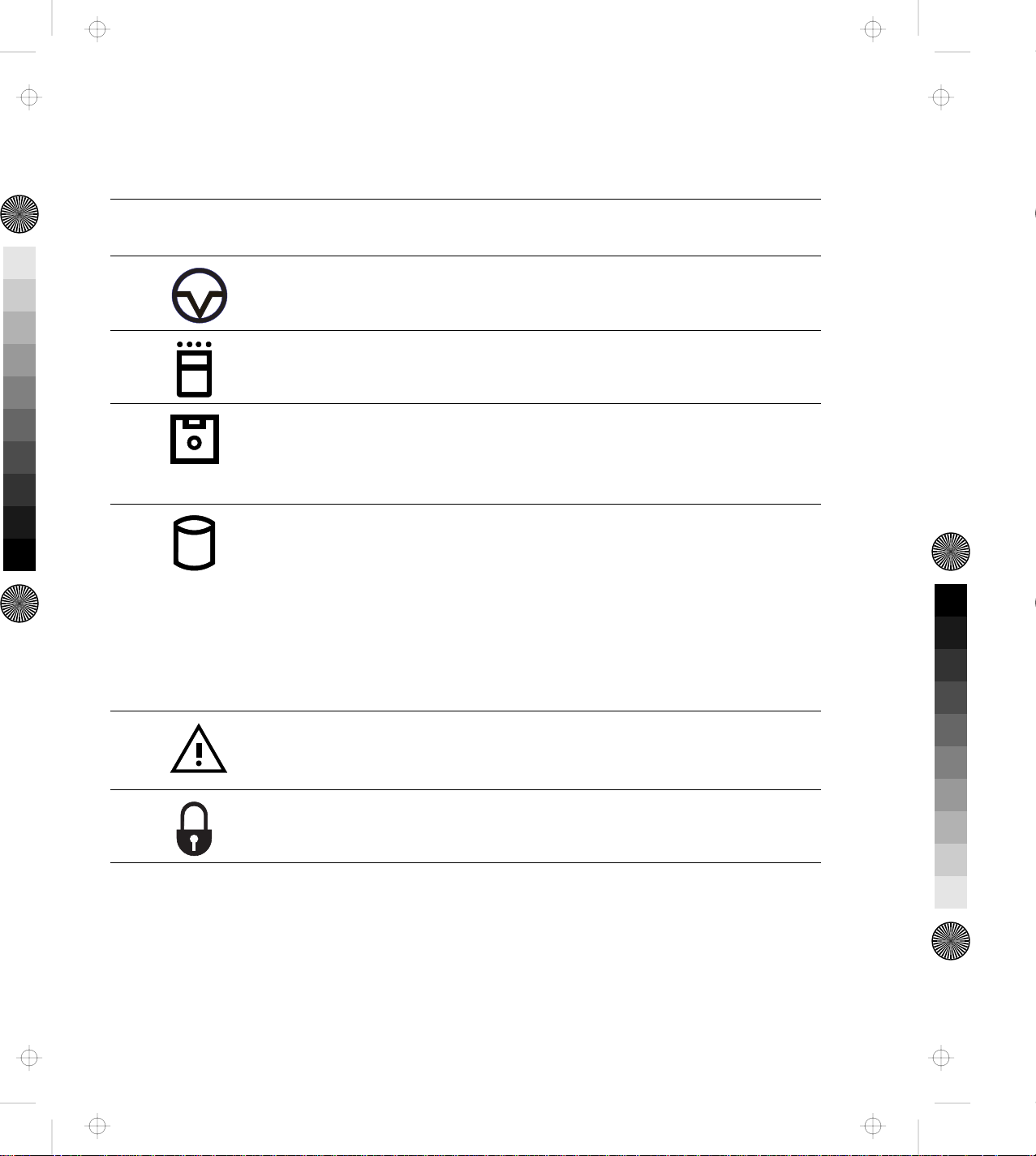
Information Notices
This User's Guide contains notices that relate to specific information or
text.
Note
Provides important hints, tips, guidance, or advice.
Warning
Indicates possible damage to programs, devices, system, or data. A
warning notice appears before the related instruction or situation in
which possible damage could occur.
Caution
Indicates situations that are potentially hazardous to you. A caution
appears in text before the instruction or situation that could be
hazardous.
Danger
Indicates situations that are potentially lethal or extremely hazardous
to you. It is indicated by the symbol ( ) and appears in text before
the instruction or situation that could be dangerous.
Important
Provides important information or guides that you should pay
attention to.
About This Manual v
Page 9

Title: C78JAMST CreationDate: 05/06/94 19:15:58
vi IBM ThinkPad Dock II User's Guide
Page 10

Title: C78JAMST CreationDate: 05/06/94 19:15:58
About This Manual ............................ iii
Information Notices . . . . . . . . . . . . . . . . . . . . . . . . . . . . v
Electrical Safety Notice ......................... xi
Chapter 1. Introduction . . . . . . . . . . . . . . . . . . . . . . . . . 1
Standard Features . . . . . . . . . . . . . . . . . . . . . . . . . . . . . 2
Checking the Items ............................ 3
Locating Dock II Features ........................ 4
Front View . . . . . . . . . . . . . . . . . . . . . . . . . . . . . . . . 4
Rear View . . . . . . . . . . . . . . . . . . . . . . . . . . . . . . . . 6
Dock II Status Indicators ......................... 8
Changing Modes . . . . . . . . . . . . . . . . . . . . . . . . . . . . . . 10
Warning Function . . . . . . . . . . . . . . . . . . . . . . . . . . . . . 10
Contents
Chapter 2. Using the Dock II ..................... 13
Setting Up the Dock II .......................... 14
Docking and Undocking the Computer ................ 16
Rules of Docking and Undocking .................. 16
Docking the Computer ........................ 19
Undocking the Computer ....................... 24
Turning On and Off the Computer and the Dock II ........ 28
Chapter 3. Using the Security Features ............... 29
Using the Security Lock ......................... 30
Security Lock Description ....................... 30
Key Positions and Their Functions ................. 31
Securing the Dock II with the Kensington Lock ........... 32
Securing the PCMCIA Cards ...................... 33
Ordering Additional Security Lock Keys ............... 35
Chapter 4. Installing and Removing IBM Options ........ 37
Handling Internal Options ........................ 38
Using the Display Shelf ......................... 39
Installing and Removing Devices in the 1-Inch-High Drive Space 46
Installing Devices . . . . . . . . . . . . . . . . . . . . . . . . . . . . 46
Copyright IBM Corp. 1994 vii
Page 11

Title: C78JAMST CreationDate: 05/06/94 19:15:58
Removing Devices . . . . . . . . . . . . . . . . . . . . . . . . . . . 51
Installing and Removing Devices in the Half-High Drive Space . 52
Installing Devices . . . . . . . . . . . . . . . . . . . . . . . . . . . . 52
Removing Devices . . . . . . . . . . . . . . . . . . . . . . . . . . . 56
Installing and Removing the ISA Adapter Cards .......... 57
Installing the Adapter Cards ..................... 57
Removing the Adapter Cards .................... 60
Using the PCMCIA Cards ........................ 61
Connecting External SCSI Devices ................... 62
Connecting Other External Options .................. 63
Removing and Installing the Top Cover ................ 64
Removing the Top Cover ....................... 64
Installing the Top Cover ....................... 66
Removing and Installing the Blank Bezel ............... 68
Removing the Blank Bezel for the 1-Inch-High and Half-High
Drives . . . . . . . . . . . . . . . . . . . . . . . . . . . . . . . . . . 69
Installing the Blank Bezel for the 1-Inch-High and Half-High
Drives . . . . . . . . . . . . . . . . . . . . . . . . . . . . . . . . . . 69
Removing the Blank Bezel for the ISA Adapter Cards ..... 70
Installing the Blank Bezel for the ISA Adapter Cards ...... 70
Releasing the Latch ............................ 71
Chapter 5. Using the SCSI Controller ................ 73
Default Settings . . . . . . . . . . . . . . . . . . . . . . . . . . . . . . 74
Connecting Peripherals . . . . . . . . . . . . . . . . . . . . . . . . . . 74
Assigning SCSI IDs .......................... 74
Terminating the SCSI Bus ....................... 75
Configuring the Host Adapter ..................... 76
Running the SCSISelect Utility .................... 76
Main Menu Options .......................... 77
Switch Block Settings .......................... 78
Chapter 6. Solving Problems . . . . . . . . . . . . . . . . . . . . . 81
Before Testing Is Started ......................... 83
Testing Your Dock II ........................... 85
Troubleshooting Charts . . . . . . . . . . . . . . . . . . . . . . . . . . 88
viii IBM ThinkPad Dock II User's Guide
Page 12

Title: C78JAMST CreationDate: 05/06/94 19:15:58
Computer Keyboard Problems .................... 88
External Display (CRT) Problems .................. 89
External Keyboard, External Numeric Keypad, or Pointing
Device Problems . . . . . . . . . . . . . . . . . . . . . . . . . . . 91
Intermittent Problems . . . . . . . . . . . . . . . . . . . . . . . . . 93
LCD Problems . . . . . . . . . . . . . . . . . . . . . . . . . . . . . 94
Option Problems . . . . . . . . . . . . . . . . . . . . . . . . . . . . 96
Printer Problems . . . . . . . . . . . . . . . . . . . . . . . . . . . . 99
Other Problems . . . . . . . . . . . . . . . . . . . . . . . . . . . . . 99
Getting Service . . . . . . . . . . . . . . . . . . . . . . . . . . . . . . 101
Appendix A. Starting Up the Operating System ........ 103
Planning for the Operating System Startup ............. 104
Starting DOS . . . . . . . . . . . . . . . . . . . . . . . . . . . . . . . 106
Starting the OS/2 2.1 Operating System ............... 110
Appendix B. Using the SCSI Support Software ......... 115
Installing EZ-SCSI for Windows ................... 117
Installing EZ-SCSI for DOS ...................... 118
Reinstalling Adaptec EZ-SCSI ..................... 119
Viewing More Online Information .................. 120
readme.txt File . . . . . . . . . . . . . . . . . . . . . . . . . . . . 120
Adaptec SCSI Interrogator ..................... 120
Formatting Utilities . . . . . . . . . . . . . . . . . . . . . . . . . . . 121
scsifmt . . . . . . . . . . . . . . . . . . . . . . . . . . . . . . . . . 121
Command Line Options ....................... 121
Running scsifmt . . . . . . . . . . . . . . . . . . . . . . . . . . . 121
afdisk . . . . . . . . . . . . . . . . . . . . . . . . . . . . . . . . . . 124
Command Line Option ....................... 125
Running afdisk . . . . . . . . . . . . . . . . . . . . . . . . . . . . 125
General Hardware Troubleshooting ................. 131
Technical Support . . . . . . . . . . . . . . . . . . . . . . . . . . 132
Appendix C. Using the Selectable Program Load ........ 133
Appendix D. Specifications . . . . . . . . . . . . . . . . . . . . . 135
Contents ix
Page 13

Title: C78JAMST CreationDate: 05/06/94 19:15:58
Physical Characteristics . . . . . . . . . . . . . . . . . . . . . . . . . 135
Environmental Requirements . . . . . . . . . . . . . . . . . . . . . 135
Temperature, Relative Humidity, and Wet Bulb Temperature 135
Maximum Altitude . . . . . . . . . . . . . . . . . . . . . . . . . . 135
Electrical Characteristics . . . . . . . . . . . . . . . . . . . . . . . . 136
Audio-Circuit Specifications . . . . . . . . . . . . . . . . . . . . . . 136
Speaker-In to Audio-Out ...................... 136
Speaker-In to Headphone Jack ................... 136
Speaker-In to Embedded Speaker ................. 137
IBM Power Cords ............................ 137
Appendix E. Product Warranties, Notices, and Statements .. 141
Notices . . . . . . . . . . . . . . . . . . . . . . . . . . . . . . . . . . 146
Trademarks . . . . . . . . . . . . . . . . . . . . . . . . . . . . . . . . 146
Federal Communications Commission (FCC) Statement ..... 147
Canadian Department of Communications Compliance Statement 147
Avis de conformité aux normes du ministère des
Communications du Canada ..................... 148
European Community (EC) Directive Conformance Statement . 148
Index . . . . . . . . . . . . . . . . . . . . . . . . . . . . . . . . . . . 149
x IBM ThinkPad Dock II User's Guide
Page 14
Title: C78JAMST CreationDate: 05/06/94 19:15:58
CAUTION:
Do not operate the Dock II with the top cover removed. To install
the top cover, see “Installing the Top Cover” on page 66.
DANGER:
Power is controlled by the power switch of the Dock II or the
computer. For emergencies, always use easily accessible electrical
outlets to turn off the power by unplugging the Dock II power
cord. The outlet should be installed near the Dock II and should
be easily accessible.
Electrical Safety Notice
DANGER:
To avoid a shock hazard, do not connect or disconnect any cables
or perform installation, maintenance, or reconfiguration of this
product during an electrical storm.
Copyright IBM Corp. 1994 xi
Page 15
Title: C78JAMST CreationDate: 05/06/94 19:15:58
To avoid a shock hazard:
DANGER:
The power cord must be connected to an outlet that has been
properly wired and grounded according to your local wiring
rules.
This equipment must have an earth ground.
Apparaten skall anslutas till jordat uttag när den ansluts till
ett nätverk.
Jordet stikkontakt skal benyttes når apparatet tilkobles
datanett.
Laite on liitettävä suojakosketinspistorasiaan.
Any equipment to which this product is attached must also be
connected to an outlet that has been properly wired and
grounded according to your local wiring rules.
xii IBM ThinkPad Dock II User's Guide
Page 16
Title: C78JAMST CreationDate: 05/06/94 19:15:58
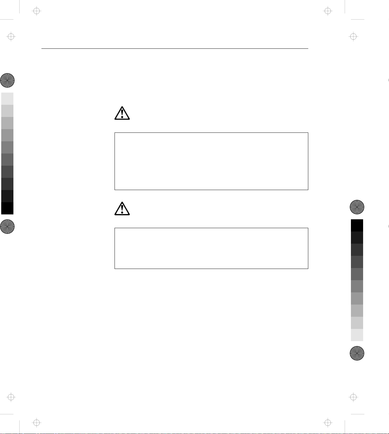
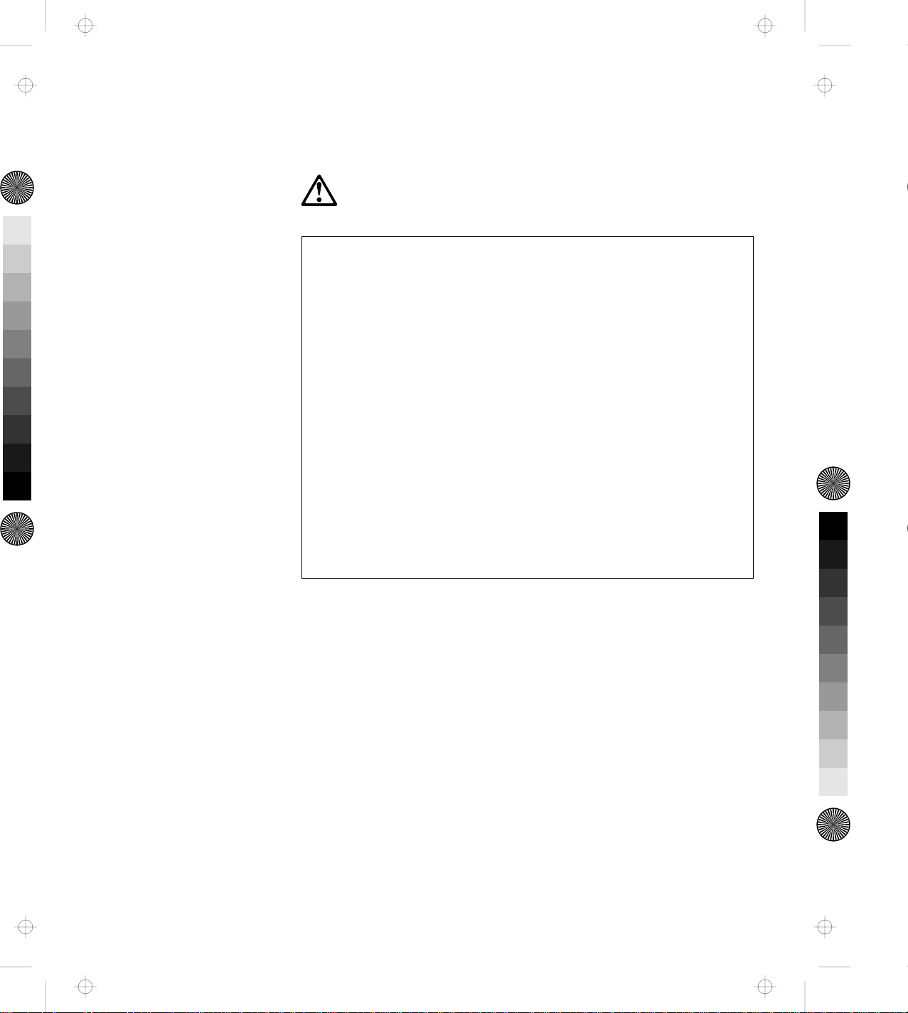
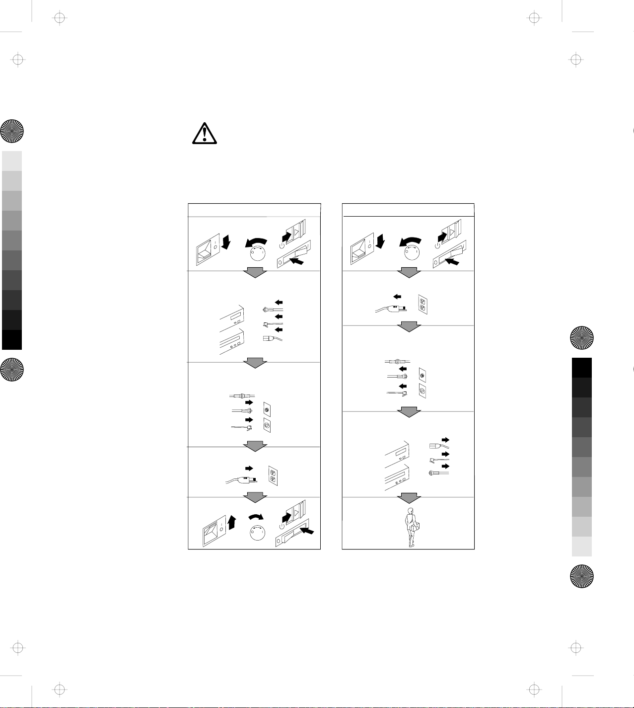
DANGER:
Electrical current from power, telephone, and communication
cables is hazardous. To avoid shock hazard, connect and
disconnect cables as shown below when installing, moving or
opening the covers of this product or attached devices. The
power cord must be used with a properly-grounded outlet.
Turn everything OFF.
To C o nn ec t
To Disconnect
Turn everything OFF.
First, attach all cables to devices.
Attach signal cables to
receptacles.
Attach power cord to outlet.
Turn device ON.
Note: In the U.K., by law, the telephone
line cable must be connected after the
power cord.
First, remove power cord from
outlet.
Rem ove signal cables from
receptacles.
Rem ove all cables from devices.
Note: In the U.K., by law, the power
cord must be disconnected after the
te le p ho n e lin e ca b le .
Electrical Safety Notice xiii
Page 17

Title: C78JAMST CreationDate: 05/06/94 19:15:58
xiv IBM ThinkPad Dock II User's Guide
Page 18

Title: C78JAMST CreationDate: 05/06/94 19:15:58
The Dock II provides expandability for the following IBM ThinkPad
computer systems (hereafter called the computer) providing the same
usability as a desktop computer system.
IBM ThinkPad 750 family
IBM ThinkPad 755 family
IBM ThinkPad 360 family
Portability of your computer is made easier because computer options
are installed in the Dock II, and docking and undocking are
effortlessly done. After your computer is docked to the Dock II, you
can readily use it with the Fail-safe Docking and Plug-and-Play
Ready features.
Chapter 1. Introduction
The Dock II has enhanced security features to protect it from theft
and unauthorized use.
This chapter contains:
Standard Features . . . . . . . . . . . . . . . . . . . . . . . . . . . . . 2
Checking the Items ............................ 3
Locating Dock II Features ........................ 4
Front View . . . . . . . . . . . . . . . . . . . . . . . . . . . . . . . . 4
Rear View . . . . . . . . . . . . . . . . . . . . . . . . . . . . . . . . 6
Dock II Status Indicators ......................... 8
Changing Modes . . . . . . . . . . . . . . . . . . . . . . . . . . . . . . 10
Warning Function . . . . . . . . . . . . . . . . . . . . . . . . . . . . . 10
Copyright IBM Corp. 1994 1
Page 19

Title: C78JAMST CreationDate: 05/06/94 19:15:58
Standard Features
The following summarizes the standard features on the Dock II.
Audio Features Speaker-in jacks
Audio-out jacks
A headphone jack
Stereo speakers
Compartments for CD-ROM drives
Security Features Security key lock
PCMCIA** card lock
A keyhole for Kensington** lock
Cable Management
Features
Desktop-Equivalent
Features
An external diskette drive connector
A keyboard/numeric keypad connector
A mouse/pointing device connector
A parallel connector
A serial connector
A SVGA connector
Two full-size ISA adapter card slots
A 1-inch-high drive space
A half-high drive space
External SCSI-II device connectors
Two PCMCIA slots
**
PCMCIA is a trademark of Personal Computer Memory Card International Association, and Kensington is a
trademark of Kensington Microware Inc.
2 IBM ThinkPad Dock II User's Guide
Page 20
Title: C78JAMST CreationDate: 05/06/94 19:15:58
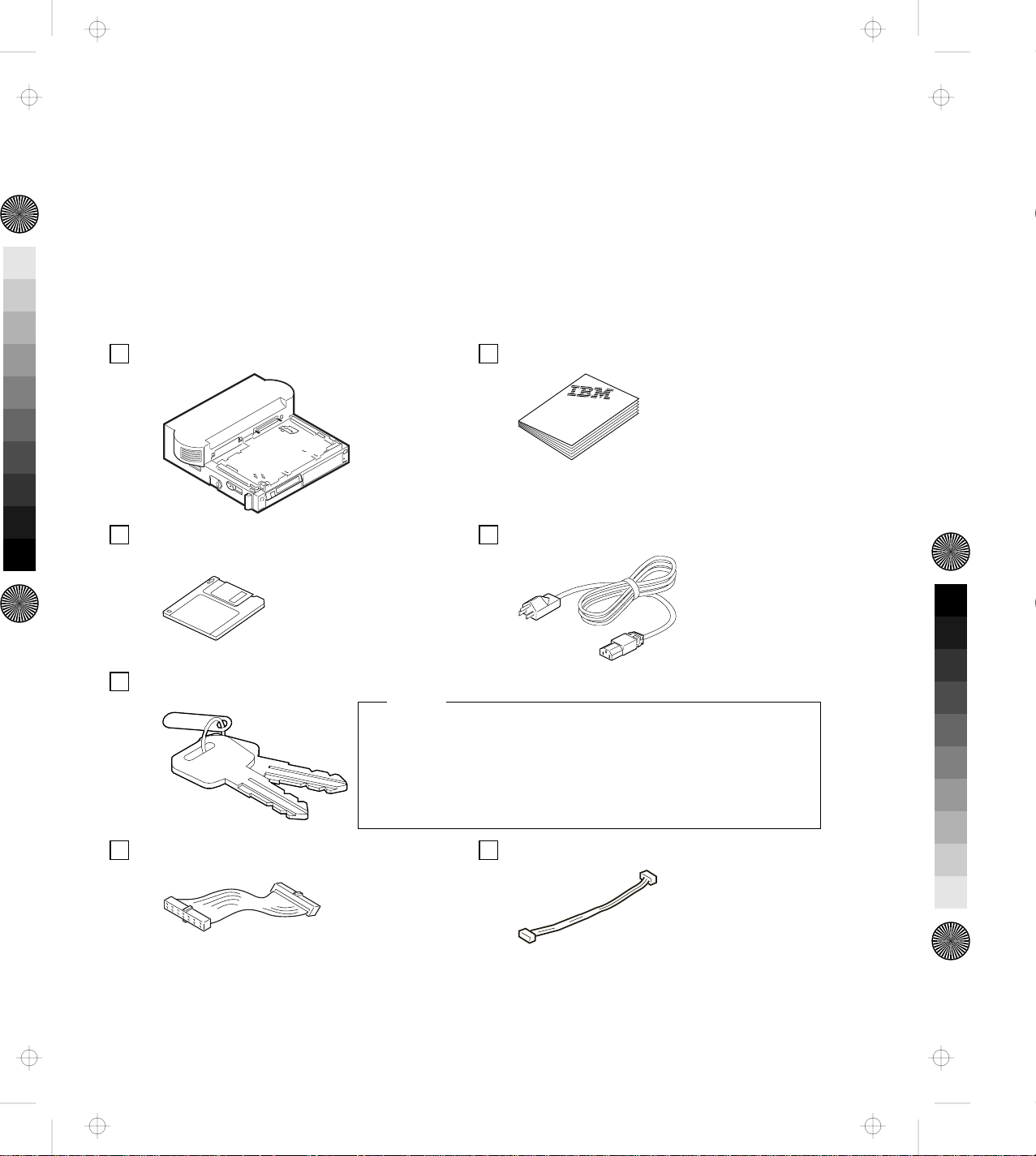
Checking the Items
Check that you have the following items.
If any are missing or damaged, call your IBM marketing
representative or dealer.
Dock II Manual
Option Diskette Power Cord
Security Lock Keys
Notes
1. An extra key is provided as a spare.
2. The key number is necessary when replacing lost keys.
See “Ordering Additional Security Lock Keys” on
page 35.
IDE Cable CD-ROM Extension Cable
Chapter 1. Introduction 3
Page 21
Title: C78JAMST CreationDate: 05/06/94 19:15:58
Locating Dock II Features
This section identifies the features for the Dock II. Symbols for
connectors are printed on the back of the Dock II above each
connector for easy identification.
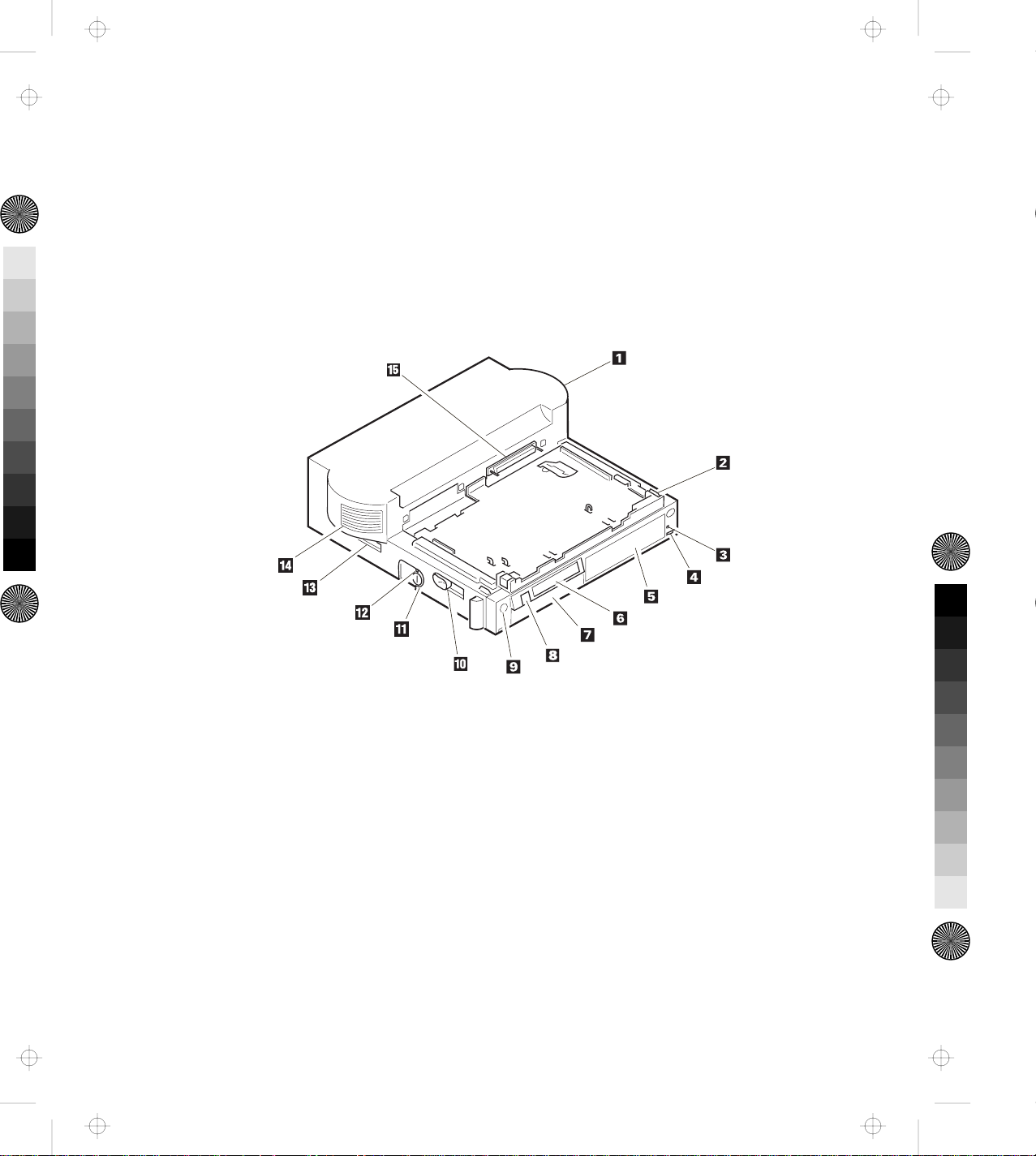
Front View
4 IBM ThinkPad Dock II User's Guide
Page 22
Title: C78JAMST CreationDate: 05/06/94 19:15:58
1 Top Cover
2 Tray is where the
computer is placed for
docking.
3 Headphone Jack is where
the plug of the stereo
headphone is connected.
Note
When the stereo
headphone plug is
connected to this jack, the
speakers do not operate.
4 Volume Control adjusts
the loudness of the speakers
and headphone.
5 Half-High Drive Space
accommodates one storage
device. The blank bezel is
removed when installing a
removable-media device.
6 Status Indicators
indicate the current status
of the Dock II by their
on/off status. For more
information about the status
indicators, see “Dock II
Status Indicators” on
page 8.
7 1-Inch-High Drive
Space accommodates one
storage device. The blank
bezel is removed when
installing a
removable-media device.
8 Power Switch turns the
computer on or off. See
“Turning On and Off the
Computer and the Dock II”
on page 28 for more
information.
9 Eject Switch unlatches
the tray and allows docking
or undocking.
1 Eject Lever ejects the
computer from the
connector of the Dock II.
11 Security Lock secures
various features on the Dock
II, depending on the position
of the key. This prevents the
top cover and the contents of
the Dock II from being
removed, prevents
unauthorized persons from
using the Dock II by securing
the power, and prevents the
computer from being
undocked from the Dock II.
(For more information, see
“Using the Security Lock” on
page 30.)
12 Unlatch Hole unlatches
the tray to undock the
computer in an emergency.
13 Reserved. (Always keep
this lever toward the rear of
the Dock II.)
14 Left Speaker
15 Computer Connector
(male-type, 240-pin) connects
the computer.
Chapter 1. Introduction 5
Page 23
Title: C78JAMST CreationDate: 05/06/94 19:15:58
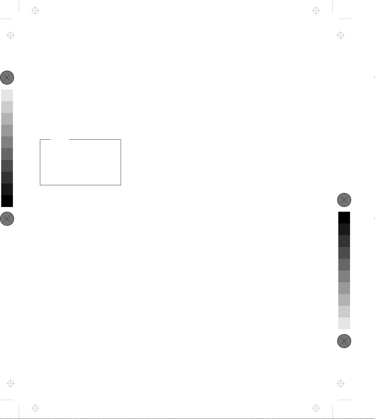
Rear View
6 IBM ThinkPad Dock II User's Guide
Page 24

Title: C78JAMST CreationDate: 05/06/94 19:15:58
16 Keyhole for Kensington
physically secures the Dock II
from theft. For more
information, see “Securing the
Dock II with the Kensington
Lock” on page 32.
17 Speaker-in and
Audio-out Jacks connect
external audio equipment to
use speakers in the Dock II,
and to use external speakers,
respectively.
18 Parallel Connector
(25-pin) connects a printer
signal cable.
19 Serial Connector (9-pin)
connects a modem or
serial-printer signal cable.
2 Mouse/Pointing Device
Connector (6-pin) connects a
mouse or other pointing
device cable.
21 Keyboard/Numeric
Keypad Connector (6-pin)
connects the keyboard cable
or the numeric keypad
cable.
Important
1. Use this connector if
you use an external
keyboard or a
numeric keypad.
2. The keyboard
(numeric keypad) on
the computer cannot
be used when the
external keyboard
(external numeric
keypad) is attached
through this
connector.
3. You cannot connect
a mouse or other
pointing device to a
external numeric
keypad that is
connected to this
connector. Connect
the mouse or other
pointing device
directly to the
mouse/pointing
device connector.
22 External SCSI Connector
(50-pin) connects an external
SCSI (Small Computer System
Interface) II device cable.
23 External Display
Connector (15-pin) connects
the display signal cable of an
external display that supports
Video Graphics Array (VGA)
of 640 by 480 resolution and
Super VGA (SVGA)
resolution.
24 External Diskette Drive
Connector (26-pin) connects
the 3.5-inch diskette drive
that has been removed from
the computer and set up with
the IBM ThinkPad 750 FDD
External Attachment Kit (an
IBM option).
25 Power Cord Connector
connects the ac power cord.
26 PCMCIA Slots
accommodate PCMCIA cards.
27 ISA Slots connects ISA
card connectors.
28 Right Speaker
Chapter 1. Introduction 7
Page 25
Title: C78JAMST CreationDate: 05/06/94 19:15:58
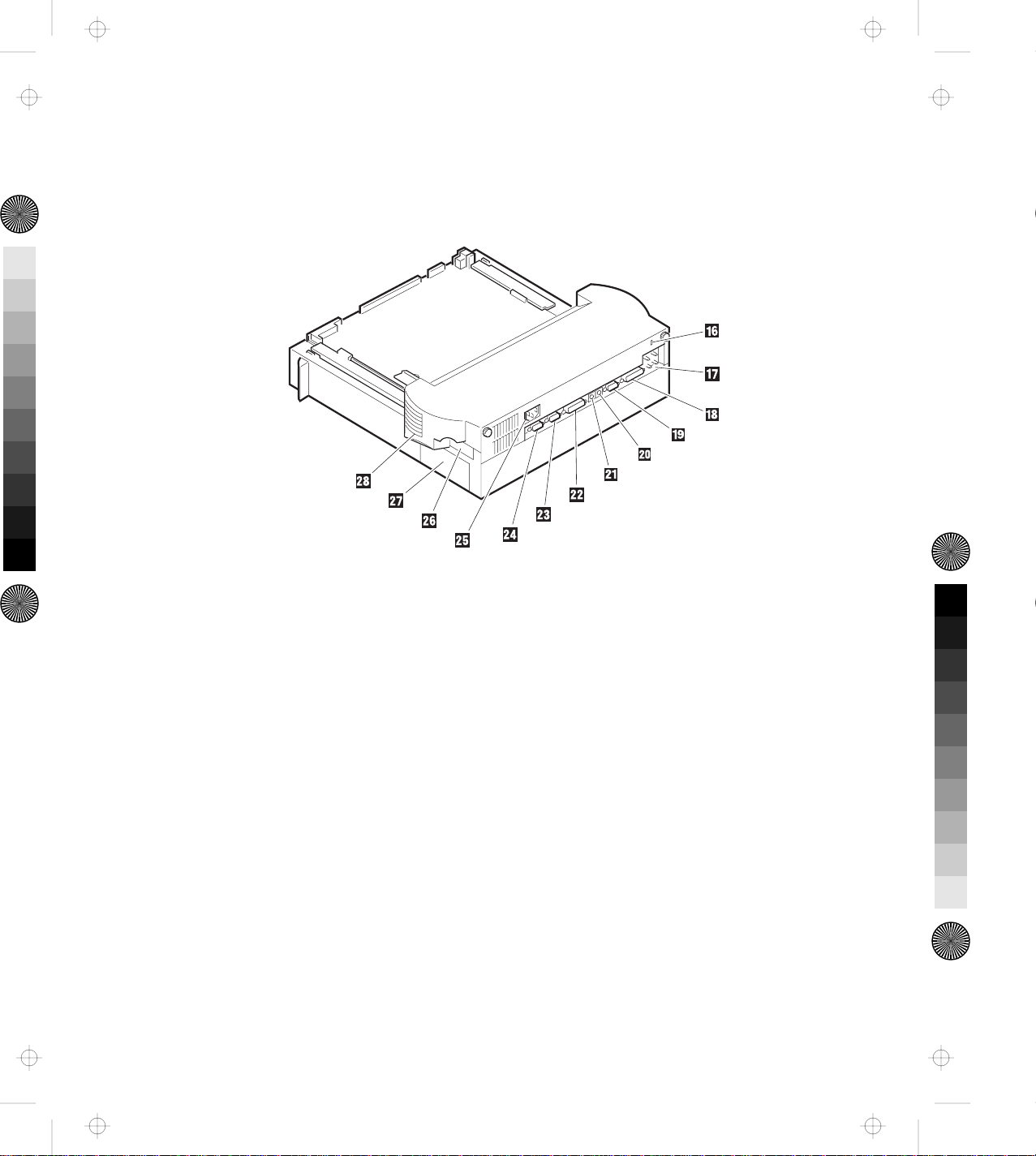
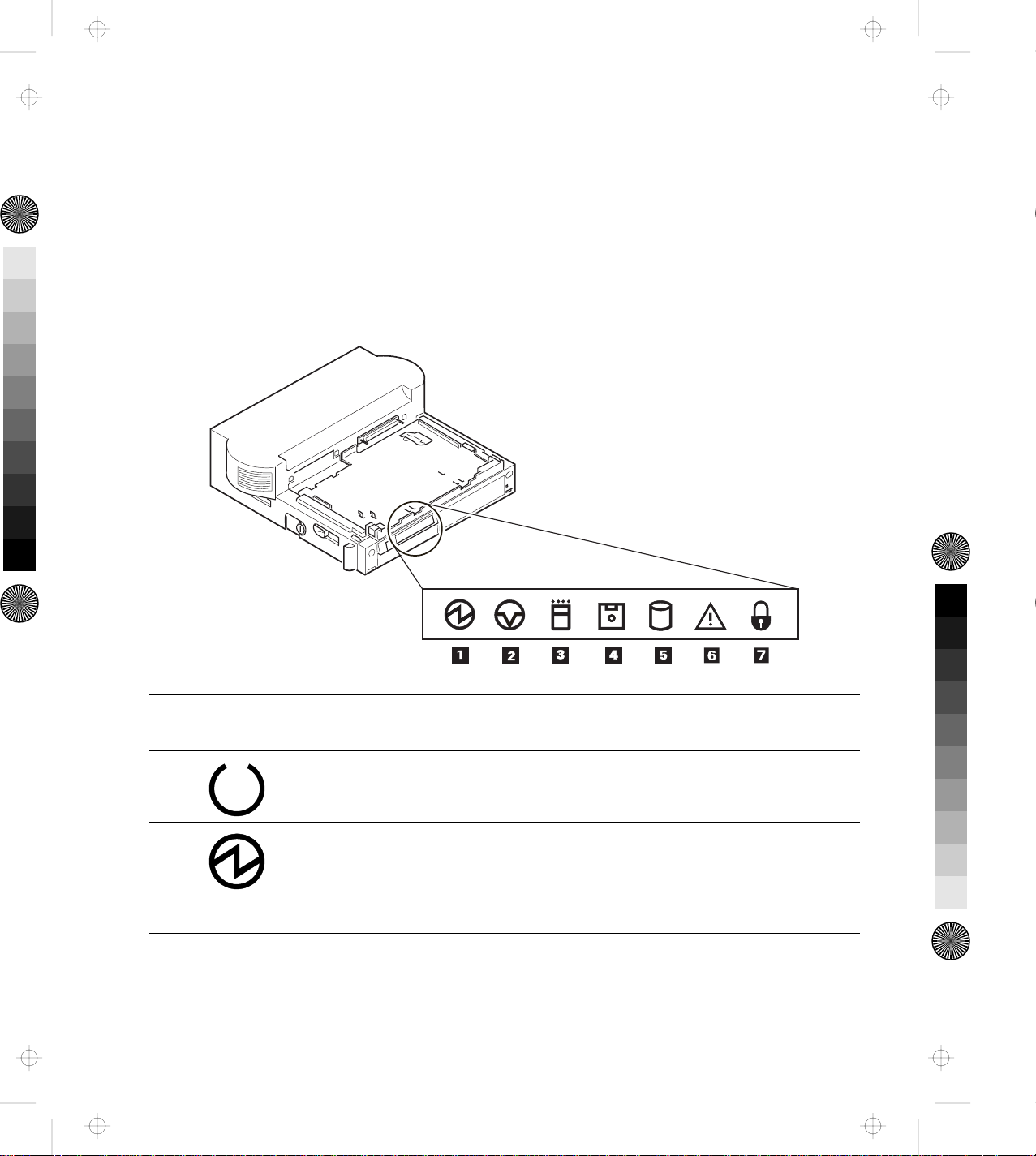
Dock II Status Indicators
The LCD status indicators show the current status of the Dock II by
their On/Off states or by blinking.
The following figure and table show the name and meaning of each
LCD indicator.
Symbol
Name of LCD
Indicator
1
1
1
LCD
Status Meaning
1
1
1 Docked On The computer is correctly docked with the
Dock II.
1 Power-On On The computer power is turned on.
Note: The "Docked" indicator changes to the
"Power-On" indicator when the
computer power is turned on.
8 IBM ThinkPad Dock II User's Guide
Page 26
Title: C78JAMST CreationDate: 05/06/94 19:15:58
Symbol
Name of LCD
Indicator
LCD
Status Meaning
2 Suspend Status On The computer is in suspend status.
3 PC Card In-Use On An inserted PC card (PCMCIA card) is
accessed.
4 Diskette Drive
In-Use
On The diskette drive in the computer is used.
When an external diskette drive is used, the
indicator on the IBM ThinkPad FDD External
Attachment Kit turns on.
5 Hard Disk In-Use On Either of the following is accessed.
The ThinkPad hard disk drive in the
computer
The ThinkPad hard disk drive in the
Dock II
The IDE hard disk drive in the Dock II
Internal or external SCSI devices
6 Warning On
or
Blink
Turns on or blinks to alert users about
operating conditions. For more information,
see “Warning Function” on page 10.
7 Security Key On Security key is locked.
Chapter 1. Introduction 9
Page 27
Title: C78JAMST CreationDate: 05/06/94 19:15:58
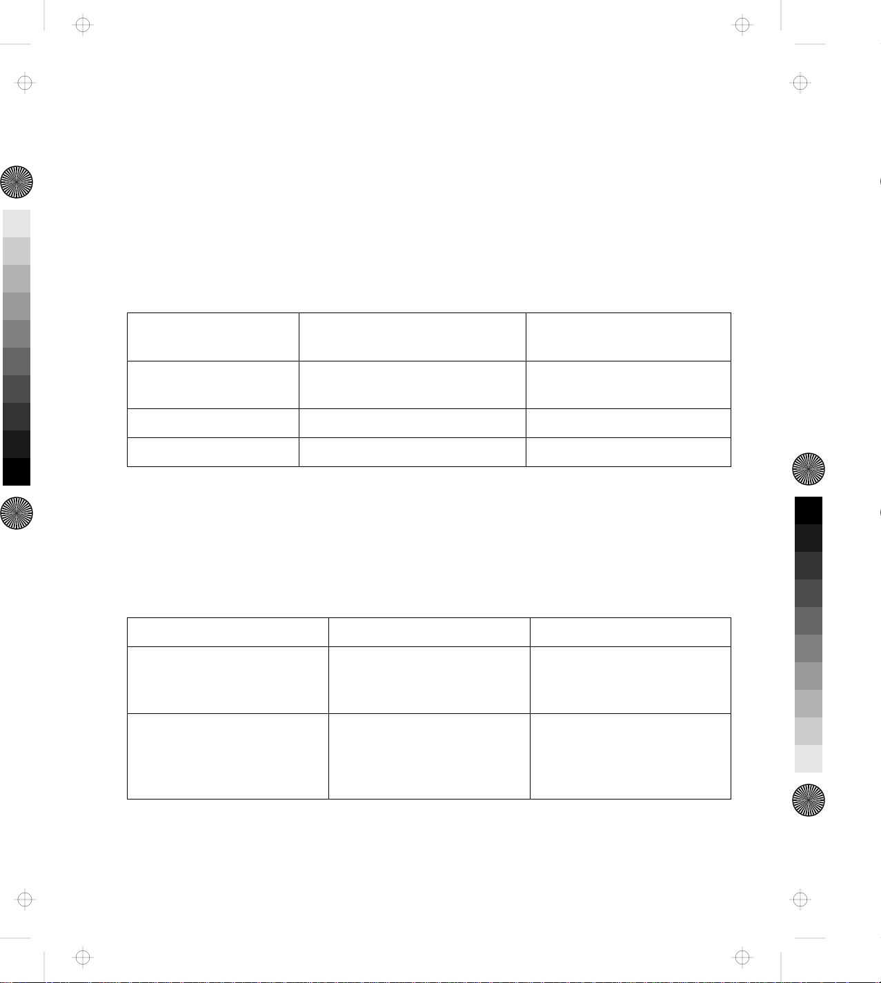
Changing Modes
When you are operating a computer docked to the Dock II, you
cannot put the computer in hibernation mode. You will hear a
warning beep from the computer if you attempt this. However, you
can enter suspend and standby modes. The following table
summarizes these conditions.
Attempt to Enter Can the Computer Enter the
Mode?
Suspend Mode Yes Power-on password is
Standby Mode Yes None
Hibernation Mode No None
Is a Password Needed to
Return to Operating Mode?
needed if you have set one.
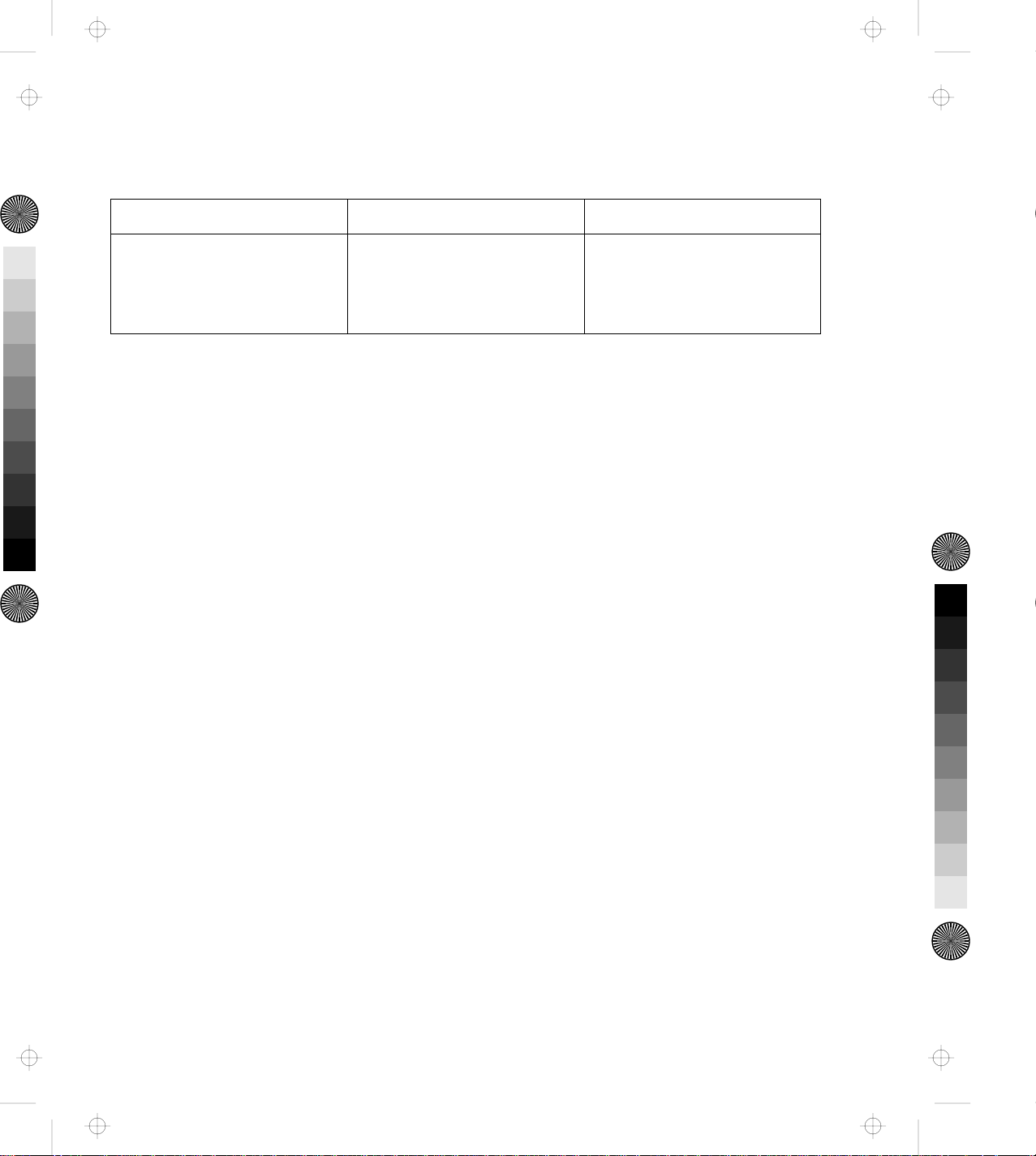
Warning Function
A combination of the warning indicator and the beep is used to alert
users about operating conditions. The combination is different
depending on the type and mode of the computer docked or
undocked. The following table summarizes the warnings.
Warning Cause How to Stop Warning
Beep sounds continuously
and the warning indicator
blinks.
A computer of the 750
series was docked during its
HOT/WARM status.
Undock or shut down the
computer.
Intermittent beep repeats
and the warning indicator
turns on.
10 IBM ThinkPad Dock II User's Guide
The eject switch was
pressed while a computer of
the 750 series was in the
HOT/WARM status.
Wait for timeout.
Page 28
Title: C78JAMST CreationDate: 05/06/94 19:15:58
Warning Cause How to Stop Warning
Beep sounds twice and the
warning indicator turns on
twice.
The eject switch was
pressed while the security
lock was at the locked
position.
Wait for timeout.
Chapter 1. Introduction 11
Page 29

Title: C78JAMST CreationDate: 05/06/94 19:15:58
12 IBM ThinkPad Dock II User's Guide
Page 30

Title: C78JAMST CreationDate: 05/06/94 19:15:58
This chapter contains rules and procedures for the initial and basic
operations for using the Dock II.
This chapter contains:
Setting Up the Dock II .......................... 14
Docking and Undocking the Computer ................ 16
Rules of Docking and Undocking .................. 16
Rules of Docking (750 Series) ................... 16
Rules of Undocking (750 Series) ................. 18
Rules of Docking (755 and 360 Series) .............. 18
Rules of Undocking (755 and 360 Series) ............ 18
Docking the Computer ........................ 19
Undocking the Computer ....................... 24
Turning On and Off the Computer and the Dock II ........ 28
Chapter 2. Using the Dock II
Copyright IBM Corp. 1994 13
Page 31

Title: C78JAMST CreationDate: 05/06/94 19:15:58
Setting Up the Dock II
Before you dock the computer to the Dock II, do the following.
1. If you install either the CD-ROM drive, tape backup unit, or other SCSI devices, do the
following:
Setup the SCSI controller. Go to Chapter 5, “Using the SCSI
Controller” on page 73.
Install the option device drivers and
SCSI diagnostics utility program.
2. Do the following depending on what options you will install:
To install and use the display shelf: Go to “Using the Display Shelf” on
To install devices in the 1-inch-high
drive space:
To install devices in the half-high
drive space:
To install ISA adapter cards: Go to “Installing and Removing the ISA
To use the PCMCIA cards: Go to “Using the PCMCIA Cards” on
To connect external SCSI devices: Go to “Connecting External SCSI Devices”
Go to Appendix B, “Using the SCSI
Support Software” on page 115.
page 39.
Go to “Installing and Removing Devices
in the 1-Inch-High Drive Space” on
page 46.
Go to “Installing and Removing Devices
in the Half-High Drive Space” on
page 52.
Adapter Cards” on page 57.
page 61.
on page 62.
To connect other external options: Go to “Connecting Other External
Options” on page 63.
14 IBM ThinkPad Dock II User's Guide
Page 32

Title: C78JAMST CreationDate: 05/06/94 19:15:58
If you have nothing to install or have
finished installing all options:
Go to “Docking and Undocking the
Computer” on page 16.
Chapter 2. Using the Dock II 15
Page 33

Title: C78JAMST CreationDate: 05/06/94 19:15:58
Docking and Undocking the Computer
This section describes the procedures for docking or undocking the
computer to or from the Dock II.
Rules of Docking and Undocking
When computer power is turned off, docking or undocking the
computer to or from the Dock II does not cause any problems.
When computer power is turned on, however, docking or undocking
the computer, or changing the operation mode can cause problems.
Make sure when you dock or undock the computer to or from the
Dock II you observe the following rules.
Rules of Docking (750 Series)
1. Return to operating mode.
2. Shut down the application.
3. Turn off the computer.
4. Dock the computer to the Dock II.
Do not dock the computer to the Dock II when:
An application is running on the computer (operating mode).
The computer has entered standby mode.
The computer has entered suspend mode.
The computer has entered hibernation mode.
16 IBM ThinkPad Dock II User's Guide
Page 34

Title: C78JAMST CreationDate: 05/06/94 19:15:58
When Docking is Incorrect (750 Series)
If you do not observe the docking rules, you will be notified by a
warning, and you will need to re-dock the computer. The following
table summarizes what will occur and what actions you need to take.
Current Status This Will Occur Action
Operating mode The Dock II warning
indicator blinks and
the beep sounds.
1. Undock the computer from the Dock II.
2. Follow the Rules of Docking 2 through
4 on page 16.
Standby mode 1. Undock the computer from the Dock II.
2. Follow the Rules of Docking 1 through
4 on page 16.
Suspend mode 1. Undock the computer from the Dock II.
2. Resume operating mode.
3. Follow the Rules of Docking 2 through
4 on page 16.
Hibernation
mode
When the computer is
turned on, a warning
screen appears.
1. Turn off the computer.
2. Undock the computer from the Dock II.
3. Turn on the computer.
4. Shut down the application.
5. Turn off the computer.
6. Dock the computer to the Dock II.
Chapter 2. Using the Dock II 17
Page 35

Title: C78JAMST CreationDate: 05/06/94 19:15:58
Rules of Undocking (750 Series)
1. Return to operating mode.
2. Shut down the application.
3. Turn off the computer.
4. Undock the computer from the Dock II.
Do not undock the computer from the Dock II when the computer is
in one of the following modes:
Operating mode
Standby mode
Suspend mode
When Undocking is Incorrect (750 Series)
If you do not observe the undocking rules, the warning indicator
blinks and the warning beep sounds. Retry the undocking by
observing the rules of undocking as stated above.
Rules of Docking (755 and 360 Series)
Computers can be docked to the Dock II when the computer is
turned off or turned on. For more information, read the READ.ME
file on the Utility Diskette.
Rules of Undocking (755 and 360 Series)
Computers can be undocked from the Dock II when the computer is
turned off or turned on. For more information, read the READ.ME
file on the Utility Diskette.
18 IBM ThinkPad Dock II User's Guide
Page 36

Title: C78JAMST CreationDate: 05/06/94 19:15:58
Docking the Computer
CAUTION:
Do not operate the Dock II with the top cover removed. To install
the top cover, see “Installing the Top Cover” on page 66.
To dock the computer to the Dock II, do the following:
1.
Observe the docking rules.
2.
Plug the power cord into the
power cord connector of the
Dock II.
3.
Unlock the security lock on the
left side of the Dock II by
turning the key to the middle
position.
4.
Slide and open the door 1 on
the rear of the computer.
See “Rules of Docking (750 Series)” on page 16 or “Rules of
Docking (755 and 360 Series)” on page 18.
See “Rear View” on page 6 for the location of the power
cord connector.
Chapter 2. Using the Dock II 19
Page 37

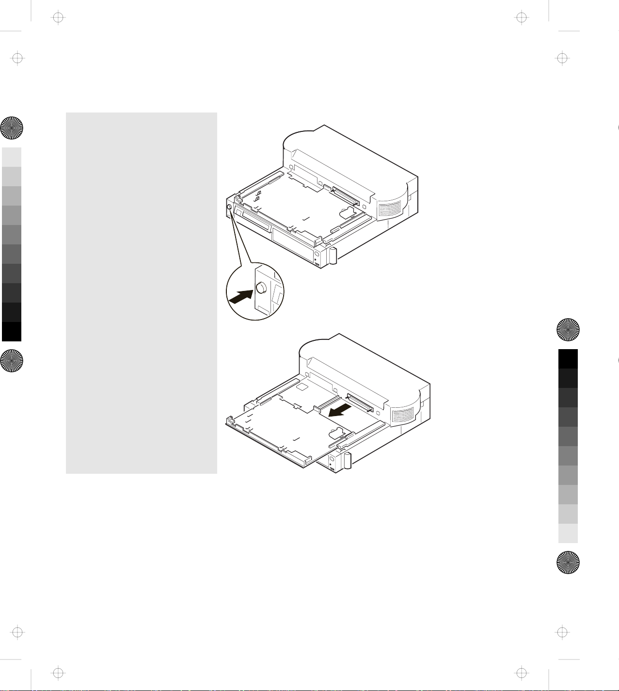
Title: C78JAMST CreationDate: 05/06/94 19:15:58
5.
Turn the computer upside down.
Slide the locking lever 1 on
the bottom of your computer
outward.
This is done to make sure that the
hard disk inside the computer
cannot be removed.
After you have removed the
computer, slide the locking
lever inward.
20 IBM ThinkPad Dock II User's Guide
Page 38
Title: C78JAMST CreationDate: 05/06/94 19:15:58
6.
Press the eject switch.
The tray is released and moves
out.
Chapter 2. Using the Dock II 21
Page 39

Title: C78JAMST CreationDate: 05/06/94 19:15:58
7.
Important
Wait at least ten seconds
before you re-dock the
computer after it has
been undocked.
Place the computer on the tray.
Using the docking-knobs 3 on
the left and right sides of the
Dock II as finger-holds, slide in
the computer until the guide
pins 1 fit into the alignment
holes 5 , the docking connector
2 fits firmly into the system
expansion connector 4 of the
computer, and the front edge of
the tray aligns with the front
edge of the Dock II.
8.
Lock the security lock on the
left side of the Dock II by
turning the key to the extreme
right position.
Remove the key and keep it in a
safe place.
22 IBM ThinkPad Dock II User's Guide
Page 40

Title: C78JAMST CreationDate: 05/06/94 19:15:58
9.
Open the LCD of the computer,
turn on all external devices;
then turn on the computer.
Notes
1. If the warning beep
sounds and the warning
indicator blinks, make
sure that the computer is
firmly docked to the
Dock II.
2. For turning on the
computer, see “Turning
On and Off the
Computer and the Dock
II” on page 28.
You have completed the installation of the computer, and can now use it.
Chapter 2. Using the Dock II 23
Page 41

Title: C78JAMST CreationDate: 05/06/94 19:15:58
Undocking the Computer
CAUTION:
Do not operate the Dock II with the top cover removed. To install
the top cover, see “Installing the Top Cover” on page 66.
To undock the computer from the Dock II, do the following:
1.
Observe the undocking rules.
2.
Unlock the security lock on the
left side of the Dock II by
turning the key to the middle
position.
See “Rules of Undocking (750 Series)” on page 18 or “Rules
of Undocking (755 and 360 Series)” on page 18.
24 IBM ThinkPad Dock II User's Guide
Page 42

Title: C78JAMST CreationDate: 05/06/94 19:15:58
3.
Press the eject switch 1 .
The eject lever 2 moves out.
Emergency Ejection
If ac power fails or the eject
switch does not work and
the eject lever does not
move out, do the following:
Make sure the security
lock is at the middle
(unlock) position.
Make sure that the
application program is
shut down, and the
computer and the Dock
II are turned off.
Unplug all power cords
connected to the Dock II
from the electrical outlet.
Insert a slim bar, such as
straightened paper clip,
into the hole 3 above
the key lock and firmly
push it until the eject
lever 2 moves out.
If the eject lever does
not move out, push the
tray toward the rear of
the Dock II; then retry
inserting and pushing
the slim bar.
Chapter 2. Using the Dock II 25
Page 43

Title: C78JAMST CreationDate: 05/06/94 19:15:58
4.
Slide the eject lever 1 to the
front of the Dock II.
The tray with the computer
moves out.
5.
Lift and undock the computer
from the Dock II.
Important
Handle the computer gently;
the hard disk is very
shock-sensitive.
1
26 IBM ThinkPad Dock II User's Guide
Page 44

Title: C78JAMST CreationDate: 05/06/94 19:15:58
6.
Push the tray until it latches.
7.
To prevent unauthorized
persons from using your Dock
II, lock the security lock on the
left side of the Dock II by
turning the key to the extreme
left position.
Remove the key and keep it in a
safe place.
Key Positions
The key positions and their
functions are explained in
“Key Positions and Their
Functions” on page 31.
You have completed the undocking of the computer from the Dock II.
Chapter 2. Using the Dock II 27
Page 45

Title: C78JAMST CreationDate: 05/06/94 19:15:58
Turning On and Off the Computer and the Dock II
If you are using a computer of the 750 series,
you can use only the power switch of the computer to turn on or
turn off the computer docked to the Dock II. The power switch of
the Dock II does not work.
If you are using a computer of the 755 or 360 series,
you can use the power switch of either the computer or the Dock II
to turn on or turn off the computer docked to the Dock II.
28 IBM ThinkPad Dock II User's Guide
Page 46

Title: C78JAMST CreationDate: 05/06/94 19:15:58
Chapter 3. Using the Security Features
This chapter contains information on how you can protect your Dock
II against theft or unauthorized use. The security is assured from the
three aspects; the security lock, the Kensington lock, and the PCMCIA
card lock.
This chapter contains:
Using the Security Lock ......................... 30
Security Lock Description ....................... 30
Key Positions and Their Functions ................. 31
Securing the Dock II with the Kensington Lock ........... 32
Securing the PCMCIA Cards ...................... 33
Ordering Additional Security Lock Keys ............... 35
Copyright IBM Corp. 1994 29
Page 47

Title: C78JAMST CreationDate: 05/06/94 19:15:58
Using the Security Lock
You can secure the Dock II and the computer by using the security
lock on the left side of the Dock II. The following describes the
security lock and shows the various ways to use it.
Security Lock Description
The security lock secures the following:
Top Cover When the top cover is locked by the security lock, the top cover is not
removable. This protects parts, optional devices, and cards installed in the
Dock II.
Computer The computer is not removable when the key position is Lock 1 or Lock 2.
When you dock or undock the computer to or from the Dock II, set the
key position to Unlock. For the key positions, see “Key Positions and Their
Functions” on page 31.
Power The Dock II power cannot be turned on when the power is locked by the
security lock.
30 IBM ThinkPad Dock II User's Guide
Page 48
Title: C78JAMST CreationDate: 05/06/94 19:15:58
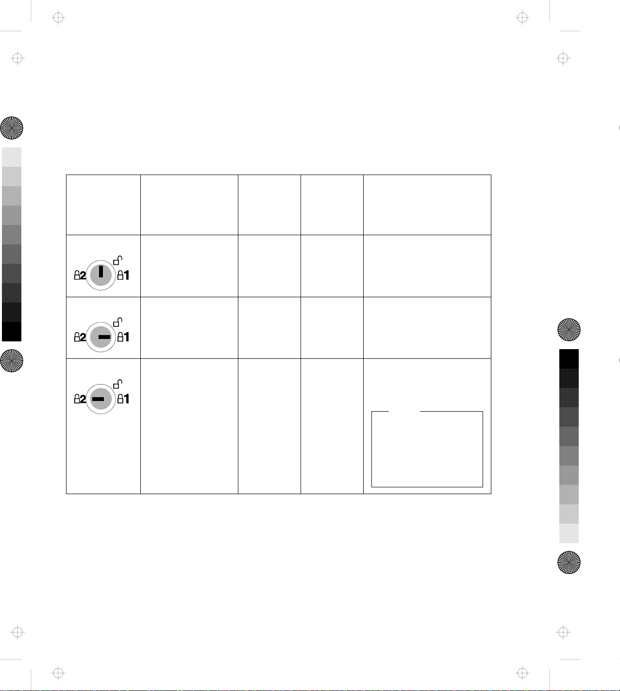
Key Positions and Their Functions
The following shows the key positions of the security lock and their
corresponding functions.
Key Position Explanation Can the
Top
Cover Be
Removed?
Unlock Turn to this
Yes Yes Yes
position to
remove the top
cover.
Lock 1 The key is turned
No No Yes
to this position
when the Dock II
is used.
Lock 2 The key is turned
No No Cannot be turned on
to this position to
prevent
unauthorized
persons from
turning on the
Dock II.
Can the
Computer
Be
Undocked?
Can the Dock II Power
Be Turned On or Off?
after the Dock II is
turned off.
Note
To turn on the Dock
II, turn the key to the
extreme right
position.
Chapter 3. Using the Security Features 31
Page 49

Title: C78JAMST CreationDate: 05/06/94 19:15:58
Securing the Dock II with the Kensington Lock
You can secure the Dock II to a
table or desk by using a
Kensington lock as shown.
Note
You must purchase the
Kensington lock from a PC
store.
For the installation of the
Kensington lock, refer to the
instruction that came with the
lock.
32 IBM ThinkPad Dock II User's Guide
Page 50

Title: C78JAMST CreationDate: 05/06/94 19:15:58
Securing the PCMCIA Cards
You can secure the PCMCIA cards inserted into the Dock II from
theft by using the PCMCIA card lock bar.
To install and secure the PCMCIA cards, do the following:
1.
Remove the top cover.
2.
Lift the PCMCIA card lock bar
1 and remove it.
Save the removed bar for the
later use.
See “Removing the Top Cover” on page 64.
1
Chapter 3. Using the Security Features 33
Page 51

Title: C78JAMST CreationDate: 05/06/94 19:15:58
3.
Insert the PCMCIA cards 1
until they completely stop.
Insert the PCMCIA card lock
bar 2 .
1
1
4.
Install the top cover.
See “Installing the Top Cover” on page 66.
You have completed making the PCMCIA cards secure.
34 IBM ThinkPad Dock II User's Guide
Page 52

Title: C78JAMST CreationDate: 05/06/94 19:15:58
Ordering Additional Security Lock Keys
Information for ordering additional keys may be obtained by writing
to the address given on the tag attached to the keys. When
requesting additional keys, be sure to include the key number from
the tag. An additional charge is required.
The following information should be recorded. The key number is on
the tag that is attached to the keys.
IBM Product Name ThinkPad Dock II
Key Number
Chapter 3. Using the Security Features 35
Page 53

Title: C78JAMST CreationDate: 05/06/94 19:15:58
36 IBM ThinkPad Dock II User's Guide
Page 54

Title: C78JAMST CreationDate: 05/06/94 19:15:58
Chapter 4. Installing and Removing IBM Options
Options are devices that you can attach to or install inside the Dock II
to expand the capabilities of your computer. This chapter provides
the instructions to add and remove the internal options. Instructions
for connecting external devices are also explained.
This chapter contains:
Handling Internal Options ........................ 38
Using the Display Shelf ......................... 39
Installing and Removing Devices in the 1-Inch-High Drive Space 46
Installing Devices . . . . . . . . . . . . . . . . . . . . . . . . . . . . 46
Removing Devices . . . . . . . . . . . . . . . . . . . . . . . . . . . 51
Installing and Removing Devices in the Half-High Drive Space . 52
Installing Devices . . . . . . . . . . . . . . . . . . . . . . . . . . . . 52
Removing Devices . . . . . . . . . . . . . . . . . . . . . . . . . . . 56
Installing and Removing the ISA Adapter Cards .......... 57
Installing the Adapter Cards ..................... 57
Removing the Adapter Cards .................... 60
Using the PCMCIA Cards ........................ 61
Connecting External SCSI Devices ................... 62
Connecting Other External Options .................. 63
Removing and Installing the Top Cover ................ 64
Removing the Top Cover ....................... 64
Installing the Top Cover ....................... 66
Removing and Installing the Blank Bezel ............... 68
Removing the Blank Bezel for the 1-Inch-High and Half-High
Drives . . . . . . . . . . . . . . . . . . . . . . . . . . . . . . . . . . 69
Installing the Blank Bezel for the 1-Inch-High and Half-High
Drives . . . . . . . . . . . . . . . . . . . . . . . . . . . . . . . . . . 69
Removing the Blank Bezel for the ISA Adapter Cards ..... 70
Installing the Blank Bezel for the ISA Adapter Cards ...... 70
Releasing the Latch ............................ 71
Copyright IBM Corp. 1994 37
Page 55

Title: C78JAMST CreationDate: 05/06/94 19:15:58
Handling Internal Options
Warning: Do not open the static-protective package containing the
option until you are instructed to install the option. Static electricity
can damage the option.
When you are instructed to install the option, observe these
precautions as you open the static-protective package:
Touch the static-protective package containing the option to a
metallic portion of the Dock II for at least 2 seconds. This action
reduces the static electricity from the package and from your
body.
Do not touch any exposed circuitry on the option.
Prevent other people from touching the option.
Limit your movement. Movement can cause static-electricity
buildup.
Always handle the option carefully and by its edges.
If you must put the option down after it has been removed from
the package, place the option on the static-protective package on
a level surface. Do not place the option on a metal table.
38 IBM ThinkPad Dock II User's Guide
Page 56

Title: C78JAMST CreationDate: 05/06/94 19:15:58
Using the Display Shelf
The display shelf is available as an option. It comes with the tray
cover.
To install and use the display shelf, do the following:
1.
Undock the computer from the
Dock II.
2.
Unplug all power cords of the
devices connected to the Dock II
from their electrical outlets.
See “Undocking the Computer” on page 24.
Chapter 4. Installing and Removing IBM Options 39
Page 57

Title: C78JAMST CreationDate: 05/06/94 19:15:58
3.
Install the display shelf on the
Dock II as shown.
Note
The display shelf can hold
up to 30 kg (66.1 lb).
40 IBM ThinkPad Dock II User's Guide
Page 58

Title: C78JAMST CreationDate: 05/06/94 19:15:58
4.
Install the tray cover 1 to the
tray by inserting its hooks 2
to the slots 3 on the tray.
Chapter 4. Installing and Removing IBM Options 41
Page 59

Title: C78JAMST CreationDate: 05/06/94 19:15:58
5.
Place the display to the rear of
the display shelf 1 ; then plug
the display power cord into the
display 2 . Connect the signal
cable of the display to the
display connector of the Dock II
3 and tighten the screws on
the signal cable of the display
4 .
42 IBM ThinkPad Dock II User's Guide
Page 60

Title: C78JAMST CreationDate: 05/06/94 19:15:58
6.
Connect the keyboard cable to
the external keyboard 1 and
to the keyboard connector 2
of the Dock II. Plug the power
cord into a correctly grounded
electrical outlet 3 .
Notes
1. The computer keyboard
does not work if an
external keyboard is
connected to the Dock II.
2. For the ThinkPad space
saver keyboard (black
keyboard), a cable with
three connectors is used.
Connect the two
connectors at one end of
the cable to the external
keyboard connector and
the mouse/pointing
device connector of the
Dock II, and the one
connector at the other
end of the cable to the
keyboard.
7.
Plug all power cords of the
devices connected to the Dock II
into correctly grounded
electrical outlets.
Chapter 4. Installing and Removing IBM Options 43
Page 61

Title: C78JAMST CreationDate: 05/06/94 19:15:58
8.
Dock the computer to the Dock
II.
9.
Lock the security lock on the
left side of the Dock II by
turning the key to the extreme
right position.
Remove the key and keep it in a
safe place.
See “Docking the Computer” on page 19.
44 IBM ThinkPad Dock II User's Guide
Page 62

Title: C78JAMST CreationDate: 05/06/94 19:15:58
10.
Turn on all external devices;
then turn on the Dock II and the
external display.
Note: You must turn on or off
the external display
separately from the Dock
II.
You have completed the installation of the display shelf and display.
Chapter 4. Installing and Removing IBM Options 45
Page 63

Title: C78JAMST CreationDate: 05/06/94 19:15:58
Installing and Removing Devices in the 1-Inch-High Drive Space
This section describes the procedures for installing and removing
devices in the 1-inch-high drive space.
Installing Devices
To install devices in the 1-inch-high drive space, do the following:
1.
Remove the top cover.
2.
If the device to install is in a
static-protective package,
carefully remove it from the
package.
3.
If the device to install is either
the SCSI device, the ThinkPad
hard disk drive, or the IDE
device, attach it to its optional
installation kit.
See “Removing the Top Cover” on page 64.
See “Handling Internal Options” on page 38 for their
handling.
See the manual that came with the kit for the attachment
guide.
46 IBM ThinkPad Dock II User's Guide
Page 64

Title: C78JAMST CreationDate: 05/06/94 19:15:58
4.
Attach the devices.
Cable Connectors
If cable connectors are
fastened together with a
twist-tie, undo the twist-tie
and separate them.
a)
To attach the CD-ROM drive,
do the following:
Insert the CD-ROM drive into
the 1-inch-high compartment.
Leave enough space in the back
of the drive so the cables can be
connected.
Insert the three connectors 1
of the cables in the Dock II to
the corresponding connectors of
the CD-ROM drive.
Go to the applicable step.
Device to Install Go to Step
CD-ROM drive 4a on page 47
SCSI device 4b on page 48
ThinkPad hard disk drive 4c on page 49
Tape backup unit 4d on page 50
CAUTION:
i. This CD-ROM drive uses a laser system. To ensure
correct use of this product, read the manual that came
with the CD-ROM drive carefully and keep the
manual for future reference. If the unit requires
maintenance, have it serviced by authorized
personnel.
ii. Use of controls, adjustments or the performance of
procedures other than those specified may result in
hazardous radiation exposure.
iii. To prevent direct exposure to the laser beam, do not
open the enclosure.
While pressing the connected
1
cables down so that they are not
above the CD-ROM drive, push
in the CD-ROM drive until it
completely stops and is latched.
Latch
If you need to remove
devices, you must release
the latch. See “Releasing the
Latch” on page 71.
Chapter 4. Installing and Removing IBM Options 47
Page 65

Title: C78JAMST CreationDate: 05/06/94 19:15:58
b)
To attach the SCSI device, do
the following:
Insert the SCSI device into the
1-inch-high compartment.
Leave enough space in the back
of the device so the cables can
be connected.
Insert the two connectors 1 of
the cables in the Dock II to the
corresponding connectors of the
SCSI device.
While pressing the connected
cables down so that they are not
above the SCSI device, push in
the SCSI device until it
completely stops and is latched.
Latch
If you need to remove
devices, you must release
the latch. See “Releasing the
Latch” on page 71.
1
48 IBM ThinkPad Dock II User's Guide
Page 66

Title: C78JAMST CreationDate: 05/06/94 19:15:58
c)
To attach ThinkPad hard disk
drive, do the following:
Insert the ThinkPad hard disk
drive into the 1-inch-high
compartment. Leave enough
space in the back of the device
so the cables can be connected.
Insert the connector 1 of the
flat-ribbon cable into the
connector 2 of the Dock II.
Note
If the flat-ribbon cable is not
long enough to reach the
connector 2 , unlatch the
cable clamp 3 from the
cable connector 1 and
remove the cable clamp to
extend the cable.
1
1
1
While pressing the connected
cables down so that they are not
above the ThinkPad hard disk
drive, push in the drive until it
completely stops and is latched.
Latch
If you need to remove
devices, you must release
the latch. See “Releasing the
Latch” on page 71.
Chapter 4. Installing and Removing IBM Options 49
Page 67

Title: C78JAMST CreationDate: 05/06/94 19:15:58
d)
To attach the tape backup unit,
do the following:
Insert the tape backup unit into
the 1-inch-high compartment.
Leave enough space in the back
of the device so the cables can
be connected.
Insert the two connectors 1 of
the cables in the Dock II to the
corresponding connectors of the
tape backup unit.
While pressing the connected
cables down so that they are not
above the tape backup unit,
push in the unit until it
completely stops and is latched.
Latch
If you need to remove
devices, you must release
the latch. See “Releasing the
Latch” on page 71.
1
5.
If the device to install is a
See “Removing the Blank Bezel for the 1-Inch-High and
Half-High Drives” on page 69.
removable-media device (the
CD-ROM drive or the tape
backup unit), remove the blank
bezel from the 1-inch-high drive
location on the top cover.
50 IBM ThinkPad Dock II User's Guide
Page 68

Title: C78JAMST CreationDate: 05/06/94 19:15:58
6.
Install the top cover.
Removing Devices
See “Installing the Top Cover” on page 66.
You have completed the installation of devices in the 1-inch-high drive space.
To remove devices from the 1-inch-high drive space, perform the
installation procedures in the reverse order.
Chapter 4. Installing and Removing IBM Options 51
Page 69

Title: C78JAMST CreationDate: 05/06/94 19:15:58
Installing and Removing Devices in the Half-High Drive Space
This section describes the procedures for installing and removing
devices in the half-high drive space.
Installing Devices
To install devices in the half-high drive space, do the following:
1.
Remove the top cover.
2.
If the device to install is in a
static-protective package,
carefully remove it from the
package.
3.
If the device to install is the IDE
device, attach it to its optional
installation kit.
4.
Attach the devices.
Cable Connectors
If cable connectors are
fastened together with a
twist-tie, undo the twist-tie
and separate them.
See “Removing the Top Cover” on page 64.
See “Handling Internal Options” on page 38 for their
handling.
See the manual that came with the kit for the attachment
guide.
Go to the applicable step.
Device to Install Go to Step
CD-ROM drive 4a on page 53
IDE device 4b on page 54
SCSI device 4c on page 55
52 IBM ThinkPad Dock II User's Guide
Page 70

Title: C78JAMST CreationDate: 05/06/94 19:15:58
a)
To attach the CD-ROM drive,
do the following:
Insert the CD-ROM drive into
the half-high compartment.
Leave enough space in the back
of the drive so the cables can be
connected.
Insert the audio-cable connector
1 from the Dock II to the
connector of the CD-ROM
extension cable 2 . Insert the
other connector of the extension
cable to the CD-ROM drive.
Insert other two connectors of
the cables from the Dock II to
corresponding connectors of the
CD-ROM drive.
While pressing the connected
cables down so that they are not
above the device, push in the
device compartment until it
completely stops and is latched.
CAUTION:
i. This CD-ROM drive uses a laser system. To ensure
correct use of this product, read the manual that came
with the CD-ROM drive carefully and keep the
manual for future reference. If the unit requires
maintenance, have it serviced by authorized
personnel.
ii. Use of controls, adjustments or the performance of
procedure other than those specified may result in
hazardous radiation exposure.
iii. To prevent direct exposure to the laser beam, do not
open the enclosure.
Chapter 4. Installing and Removing IBM Options 53
Page 71

Title: C78JAMST CreationDate: 05/06/94 19:15:58
b)
To attach the IDE drive, do the
following:
Insert the IDE device into the
half-high compartment. Leave
enough space in the back of the
device so the cables can be
connected.
Insert the one connector of the
IDE cable 2 to the connector
of the IDE 1 . Connect the
other connector of the IDE cable
to the connector 3 of the Dock
II.
While pressing the connected
cables down so that they are not
above the half-high
compartment, push in the IDE
drive until it completely stops
and is latched.
1
1
1
54 IBM ThinkPad Dock II User's Guide
Page 72

Title: C78JAMST CreationDate: 05/06/94 19:15:58
c)
To attach other types of SCSI
device, do the following:
Insert the SCSI device into the
half-high compartment. Leave
enough space in the back of the
device so the cables can be
connected.
Insert the connectors 1 of the
cables in the Dock II to the
corresponding connectors of the
SCSI device.
While pressing the connected
cables down so that they not are
above the half-high
compartment, push in the SCSI
device until it completely stops
and is latched.
1
5.
If the device to install is a
See “Removing the Blank Bezel for the 1-Inch-High and
Half-High Drives” on page 69.
removable-media device (the
CD-ROM drive, for example),
remove the blank bezel from the
half-high device location on the
top cover.
6.
See “Installing the Top Cover” on page 66.
Install the top cover.
Chapter 4. Installing and Removing IBM Options 55
Page 73

Title: C78JAMST CreationDate: 05/06/94 19:15:58
You have completed the installation of devices in the half-high drive space.
Removing Devices
To remove devices from the half-high drive space, perform the
installation procedures in the reverse order.
56 IBM ThinkPad Dock II User's Guide
Page 74

Title: C78JAMST CreationDate: 05/06/94 19:15:58
Installing and Removing the ISA Adapter Cards
The Dock II can accommodate two, full-size, AT-bus, 16-bit adapter
cards. This section describes the procedures for installing and
removing the adapter cards.
Installing the Adapter Cards
To install the adapter cards in the Dock II, do the following:
1.
Remove the top cover.
2.
Remove the rear cover.
See “Removing the Top Cover” on page 64.
Chapter 4. Installing and Removing IBM Options 57
Page 75

Title: C78JAMST CreationDate: 05/06/94 19:15:58
3.
Remove the screw 1 and
expansion slot cover 2 . Save
the screw for later use.
1
1
4.
If the adapter card has switches
or jumpers, use the switch and
jumper instructions supplied
with the adapter. Record any
switch or jumper information in
this guide for future reference.
58 IBM ThinkPad Dock II User's Guide
Page 76

Title: C78JAMST CreationDate: 05/06/94 19:15:58
5.
Hold the adapter card by its
edge with the components
facing upward. Align the
adapter with the support
brackets; then slide it into the
expansion slot.
6.
Push the adapter card firmly
into the connector.
7.
To secure the adapter card,
reinstall the screw you removed
in step 3 on page 58.
8.
If the inserted adapter card has
an external cable to be
connected, remove the blank
bezel that covers the ISA slots
from the top cover.
See “Rear View” on page 6 and “Removing the Blank Bezel
for the ISA Adapter Cards” on page 70.
Chapter 4. Installing and Removing IBM Options 59
Page 77

Title: C78JAMST CreationDate: 05/06/94 19:15:58
9.
Install the rear cover.
10.
Install the top cover.
You have completed the installation of the adapter card.
See “Installing the Top Cover” on page 66.
Removing the Adapter Cards
To remove the adapter cards from the Dock II, perform the
installation procedures in the reverse order.
60 IBM ThinkPad Dock II User's Guide
Page 78

Title: C78JAMST CreationDate: 05/06/94 19:15:58
Using the PCMCIA Cards
The two PCMCIA slots shown on “Rear View” on page 6 can
accommodate either of the following PCMCIA card combinations.
Type II (x2)
Type II (x1) + Type III (x1)
Type IV (x1)
The installed PCMCIA cards can be protected from theft by using the
PCMCIA card lock bar. To install the PCMCIA cards and the
PCMCIA card lock bar, see “Securing the PCMCIA Cards” on
page 33.
To remove the PCMCIA cards from the slots, remove the PCMCIA
card lock bar, if it is installed. Then press the eject button on the
right of each slot and remove the ejected cards.
Chapter 4. Installing and Removing IBM Options 61
Page 79

Title: C78JAMST CreationDate: 05/06/94 19:15:58
Connecting External SCSI Devices
You can connect external SCSI devices to the external SCSI connector
shown on “Rear View” on page 6.
Follow the installation instructions that came with the SCSI device.
Notes
1. Do not remove the system board terminator in the Dock II,
even if you are instructed to do so. The SCSI terminator
automatically controls the termination. This SCSI terminator
is not a removable part.
2. Turn on all external SCSI devices before you turn on the Dock
II.
3. Make sure you run the automatic configuration program after
connecting the external SCSI devices.
62 IBM ThinkPad Dock II User's Guide
Page 80

Title: C78JAMST CreationDate: 05/06/94 19:15:58
Connecting Other External Options
External options are devices that attach to connectors of the Dock II.
Notes
1. A mouse will not work if it is connected to the mouse
connector of the numeric keyboard.
2. The computer keyboard does not work if an external
keyboard is connected to the expansion unit.
See “Rear View” on page 6 for information about these connectors.
Symbols of connectors are printed above each connector for easy
identification.
To connect an external option, turn off the Dock II and refer to the
information supplied with the option.
Chapter 4. Installing and Removing IBM Options 63
Page 81

Title: C78JAMST CreationDate: 05/06/94 19:15:58
Removing and Installing the Top Cover
This section describes the procedures for removing and installing the
top cover of the Dock II.
Removing the Top Cover
To remove the top cover, do the following:
1.
Remove the computer from the
Dock II.
2.
Unplug all power cords of the
devices connected to the Dock II
from their electrical outlets.
3.
Unlock the security lock on the
left side of the Dock II by
turning the key to the middle
position.
4.
Make sure that the tray is fully
inserted to the rear of the Dock
II.
See “Undocking the Computer” on page 24.
64 IBM ThinkPad Dock II User's Guide
Page 82

Title: C78JAMST CreationDate: 05/06/94 19:15:58
5.
Loosen the two thumbscrews on
the rear of the Dock II. Use a
coin if the thumbscrews are
tight.
6.
Pull the top cover to the front of
the Dock II about 30 mm (1.0
in.); then lift it up.
You have completed the removal of the top cover.
Chapter 4. Installing and Removing IBM Options 65
Page 83

Title: C78JAMST CreationDate: 05/06/94 19:15:58
Installing the Top Cover
To install the top cover, do the following:
1.
Unlock the security lock on the
left side of the Dock II by
turning the key to the middle
position.
2.
Make sure that the tray is fully
inserted to the rear of the Dock
II.
3.
Place the top cover on the Dock
II about 30 mm (1.0 in.) from
the rear so that the cut-out 1
is over the security lock 2 .
66 IBM ThinkPad Dock II User's Guide
Page 84

Title: C78JAMST CreationDate: 05/06/94 19:15:58
4.
Slide the top cover until it
completely stops.
5.
Tighten the two thumbscrews.
You have completed the installation of the top cover.
Chapter 4. Installing and Removing IBM Options 67
Page 85

Title: C78JAMST CreationDate: 05/06/94 19:15:58
Removing and Installing the Blank Bezel
This section describes the procedures for removing and installing the
blank bezels.
As shown, there are three locations that the blank bezels are used.
The bezels 1 are used at the 1-inch-high and the half-high drive
locations, and should be removed when a removable-media device is
installed. The bezel 2 should be removed when ISA adapter cards
that need connection of the external cables are installed.
The top cover is removed when the bezels are installed or removed.
68 IBM ThinkPad Dock II User's Guide
Page 86
Title: C78JAMST CreationDate: 05/06/94 19:15:58
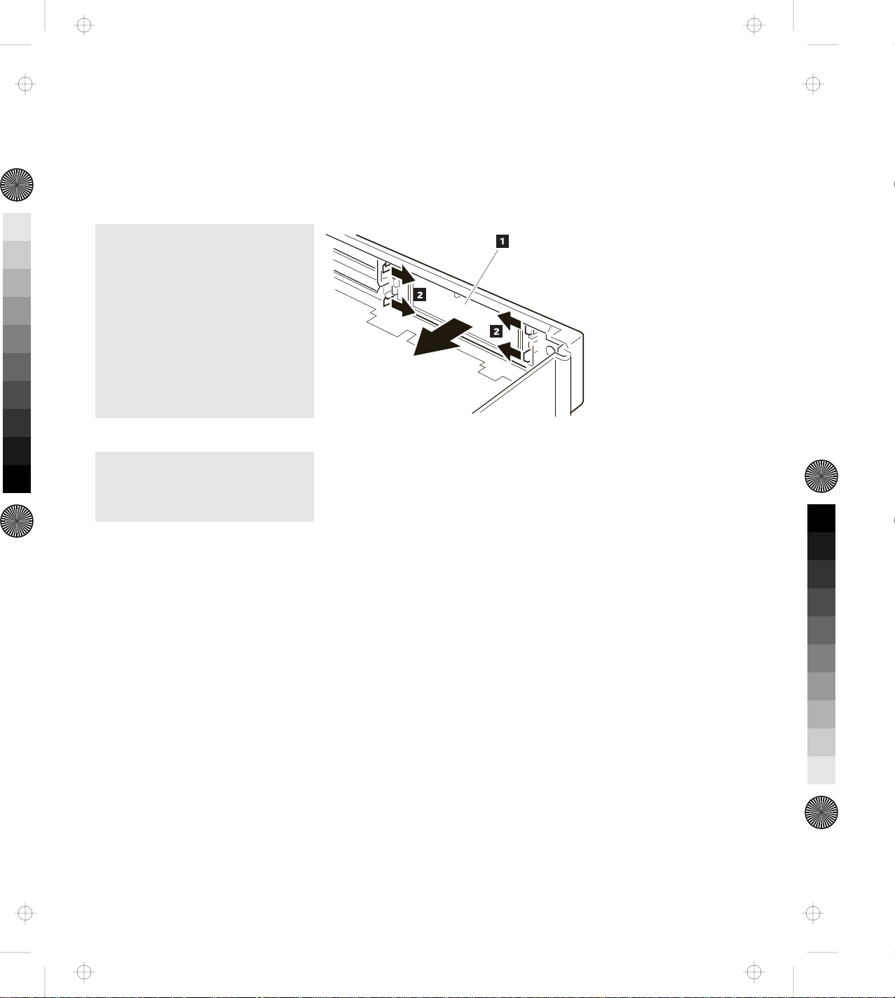
Removing the Blank Bezel for the 1-Inch-High and Half-High Drives
To remove the blank bezel, do the following:
1.
1
While pressing the latches 2
of the blank bezel 1 inward,
1
push and remove the bezel 1
from the top cover.
1
2.
Keep the removed blank bezel
for future use.
You have completed the removal of the blank bezel.
Installing the Blank Bezel for the 1-Inch-High and Half-High Drives
To install the blank bezel 1 , push it in the opposite direction (see
the previous figure) until it is latched by the latches 2 .
Chapter 4. Installing and Removing IBM Options 69
Page 87

Title: C78JAMST CreationDate: 05/06/94 19:15:58
Removing the Blank Bezel for the ISA Adapter Cards
To remove the blank bezel, do the following:
1.
Push the blank bezel 2 down
and outward with a screwdriver
1 ; then remove the bezel.
1
1
2.
Keep the removed blank bezel
for future use.
You have completed the removal of the blank bezel.
Installing the Blank Bezel for the ISA Adapter Cards
To install the blank bezel, place the bezel over the ISA slots and press
it in until it latches.
70 IBM ThinkPad Dock II User's Guide
Page 88

Title: C78JAMST CreationDate: 05/06/94 19:15:58
Releasing the Latch
The latch is installed in the 1-inch-high drive space to hold the
storage device after it is inserted. To remove the storage device, the
latch must be released.
To release the latch to remove an internal storage device, press the
latch 1 in an outward direction.
1
Chapter 4. Installing and Removing IBM Options 71
Page 89

Title: C78JAMST CreationDate: 05/06/94 19:15:58
72 IBM ThinkPad Dock II User's Guide
Page 90

Title: C78JAMST CreationDate: 05/06/94 19:15:58
Chapter 5. Using the SCSI Controller
This chapter explains how to prepare for connecting peripherals,
configuring the host adapter, and setting the switch block.
Important
This chapter must be referenced prior to the installation of SCSI
devices.
This chapter supersedes all other documents when conflicting
instructions are given. All relevant documents should be used.
This chapter contains:
Default Settings . . . . . . . . . . . . . . . . . . . . . . . . . . . . . . 74
Connecting Peripherals . . . . . . . . . . . . . . . . . . . . . . . . . . 74
Assigning SCSI IDs .......................... 74
Terminating the SCSI Bus ....................... 75
Configuring the Host Adapter ..................... 76
Running the SCSISelect Utility .................... 76
Main Menu Options .......................... 77
Switch Block Settings .......................... 78
Copyright IBM Corp. 1994 73
Page 91

Title: C78JAMST CreationDate: 05/06/94 19:15:58
Default Settings
The Dock II operates correctly with factory default settings for most
PCs. The default settings are:
Parameter Default Setting
Host Adapter SCSI ID 7
Interrupt Channel IRQ 11
Host Adapter Termination Enabled
Host Adapter BIOS Enabled at DC000h
Initiate Synchronous Negotiation Enabled
Port Address 340h–35Fh
SCSI Bus Parity Checking Enabled
SCSI Bus Reset at Host Adapter
Initialization
Greater than 1 GByte Support Disabled
BIOS Support for More than 2 Drives Disabled
SCSI Disconnection Enabled
Data Transfer Mode Programmed I/O
Send Start Unit Command Disabled
Include in BIOS Scan Enabled
Enabled
Disabling the BIOS
CD-ROM drives, tape drives, and other non-disk SCSI devices do not
use the host adapter BIOS. Therefore, if no SCSI hard disk drives are
connected to the host adapter, you can reduce bootup time if you
disable the host adapter BIOS.
Connecting Peripherals
Assigning SCSI IDs
Each device on the SCSI bus must have a different SCSI ID. When
you boot your PC, the SCAM (SCSI configured auto-magically)
protocol software included with the Dock II automatically assigns
SCSI IDs to SCAM-capable devices.
74 IBM ThinkPad Dock II User's Guide
Page 92

Title: C78JAMST CreationDate: 05/06/94 19:15:58
Conventional SCSI devices are not SCAM-capable; their SCSI IDs are
set by jumpers or switches and cannot be changed by SCAM
commands. This causes a problem only if two or more older devices
are set to the same SCSI ID, which will create a conflict. If this
happens, you must change the switch or jumper settings to a
different SCSI ID. See your SCSI peripheral documentation for
directions on how to do this.
The default host adapter ID is SCSI ID 7 and should not be
changed. Only the SCSISelect utility can change the host adapter
ID.
If you need to assign SCSI IDs manually, it is recommended that
you assign SCSI IDs 0 and 1 to the first two SCSI hard disk
drives in your system.
Terminating the SCSI Bus
The last physical SCSI device on either end of the SCSI but must have
a set of resistors called terminators. Terminators must be removed
from, or disabled on, all other devices on the SCSI bus.
The Dock II and most SCSI peripherals have built-in terminators that
can be enabled or disabled. Terminate only the devices at each end of
the SCSI bus.
Terminating the Host Adapter
Termination is enabled by default on the Dock II. You must disable
host adapter termination if you attach SCSI devices to both the
internal and external SCSI connectors.
The following table lists the three possible types of SCSI bus
configuration.
Devices Connected to SCSI Bus Host Adapter Termination
Internal devices only
Enabled
(host adapter at end of bus)
Chapter 5. Using the SCSI Controller 75
Page 93

Title: C78JAMST CreationDate: 05/06/94 19:15:58
Devices Connected to SCSI Bus Host Adapter Termination
External devices only
(host adapter at end of bus)
Internal and external devices
(host adapter in middle of bus)
The Dock II termination is controlled by the SCSISelect utility. If you
need to disable host adapter termination, first complete the physical
installation; then run this utility. (See “Configuring the Host
Adapter”)
Terminating SCSI Peripherals
1. Read the manufacturer's documentation to determine how to
enable or disable termination on SCSI peripheral devices.
2. Install or enable terminators on SCSI devices at the ends of the
SCSI bus (cable).
3. Remove or disable terminators on all other devices on the SCSI
bus.
4. Be sure the SCSI cables are connected securely. They may have
been loosened if you changed jumper or switch settings on the
peripherals.
Enabled
Disabled
Configuring the Host Adapter
The Dock II includes the menu-driven SCSISelect utility, which lets
you change settings such as host adapter termination without
opening your PC or setting switches. The SCSISelect utility also
includes disk formatting utilities.
Running the SCSISelect Utility
There are two ways to start the SCSISelect utility:
Press Ctrl+A when prompted at boot time.
At the DOS prompt type debug and press Enter.
Then at the Debug prompt (a hyphen), type:
76 IBM ThinkPad Dock II User's Guide
Page 94

Title: C78JAMST CreationDate: 05/06/94 19:15:58
g=xxxx:6
where xxxx are the first four digits of the host adapter BIOS
address in hex. (DC000h is the default address.)
Use the Up and Down Arrow keys (↑ or ↓ ) and Enter to make
selections. Press Esc at any time to return to the previous menu.
You can press F6 to restore the original default settings. To quit the
changes you made in the Configure/View Host Adapter Settings
menu, press Esc and select No when asked if you want to save the
changes.
Main Menu Options
Configure/View Host Adapter Settings
The Configuration screen displays the basic software configurable
options: IRQ, Host Adapter SCSI ID, Parity Checking, and Host
Adapter Termination. Highlight an option and press Enter to see a
list of possible values. Some options include information to help you
determine which value to select.
Note: The Configuration Manager assigns the host adapter's IRQ and
other resources at system bootup. It will override any IRQ
changes made in the SCSISelect utility.
If you select SCSI Device Configuration you can view another menu
and change these options for each device on the SCSI bus: Initiate
Synchronous Negotiation, Maximum Synchronous Transfer Rate,
Enable Disconnect, Send Start Unit Command, and Include in BIOS
Scan.
If you select Advanced Configuration Options you can view a menu
of these advanced options: Host Adapter BIOS Enable or Disable,
Extended BIOS Translation, and BIOS Support for More than 2 Drives
(DOS 5.0 and above).
SCSI Disk Utilities
When you select SCSI Disk Utilities from the Main Menu, a list of
installed SCSI devices appears. When you select a device, the
Utilities menu appears.
Chapter 5. Using the SCSI Controller 77
Page 95

Title: C78JAMST CreationDate: 05/06/94 19:15:58
Format Disk accesses the Adaptec SCSI low-level format utility. Most
SCSI devices are pre-formatted and do not need to be formatted with
this utility.
Verify Disk Media scans the selected device's media for defects. If it
finds bad blocks, it prompts you to reassign them; if you select Yes,
those blocks will no longer be used.
Switch Block Settings
The Dock II switch block 1 is located at the upper left hand corner
of the board.
1
To get access to the switch block, remove the top cover of the Dock
II. See “Removing the Top Cover” on page 64.
The following table shows all possible settings of the four switches in
the switch block. Default settings are marked with bold letters.
78 IBM ThinkPad Dock II User's Guide
Page 96

Title: C78JAMST CreationDate: 05/06/94 19:15:58
Memory Address
Switches
On Off
4
3
2
1
sw1 sw2 sw3 BIOS Address
Off
Off
Off
DC000h to DFFFFh
Off
Off
On
CC000h to CFFFFh
Off
On
Off
D4000h to D7FFFh
Off
On
On
BIOS disabled, board inactive on reset
On
Off
Off
D8000h to DBFFFh
On
Off
On
C8000h to CBFFFh
On
On
Off
D0000h to D3FFFh
On
On
On
BIOS disabled, board active on reset
sw4 Port Address
Off
On
340h to 35Fh
140h to 14Fh
Chapter 5. Using the SCSI Controller 79
Page 97

Title: C78JAMST CreationDate: 05/06/94 19:15:58
80 IBM ThinkPad Dock II User's Guide
Page 98

Title: C78JAMST CreationDate: 05/06/94 19:15:58
Computer and Dock II problems can be caused by your computer,
the Dock II, or both. To simplify diagnosing problems, isolate your
computer and diagnose it first. Then test the Dock II with the
computer docked. The diagnostic program on your computer
diagnoses the Dock II and the computer when docked. Many
problems can be diagnosed and solved with the assistance of the
self-tests and the diagnostics programs of your computer.
By using the diagnostic programs on your computer, you may be
able to solve the problem yourself or provide information to the
service representative. Make a note of all error messages and be
prepared to give them to the service representative if you need to call
for service. If the diagnostic programs on your computer cannot be
loaded, refer to the troubleshooting charts and other information
supplied with your computer.
Chapter 6. Solving Problems
The troubleshooting charts and other information in this chapter will
help you determine what corrective action to take for the Dock II.
Important
Use this chapter to test IBM products only. Other products may
cause misleading error information or incorrect computer
responses. Refer to the instructions supplied with those products
for testing information.
This chapter contains:
Before Testing Is Started ......................... 83
Testing Your Dock II ........................... 85
Troubleshooting Charts . . . . . . . . . . . . . . . . . . . . . . . . . . 88
Computer Keyboard Problems .................... 88
External Display (CRT) Problems .................. 89
External Keyboard, External Numeric Keypad, or Pointing
Device Problems . . . . . . . . . . . . . . . . . . . . . . . . . . . 91
Intermittent Problems . . . . . . . . . . . . . . . . . . . . . . . . . 93
LCD Problems . . . . . . . . . . . . . . . . . . . . . . . . . . . . . 94
Copyright IBM Corp. 1994 81
Page 99

Title: C78JAMST CreationDate: 05/06/94 19:15:58
Option Problems . . . . . . . . . . . . . . . . . . . . . . . . . . . . 96
Printer Problems . . . . . . . . . . . . . . . . . . . . . . . . . . . . 99
Other Problems . . . . . . . . . . . . . . . . . . . . . . . . . . . . . 99
Getting Service . . . . . . . . . . . . . . . . . . . . . . . . . . . . . . 101
82 IBM ThinkPad Dock II User's Guide
Page 100

Title: C78JAMST CreationDate: 05/06/94 19:15:58
Before Testing Is Started
Before starting the test, do the following:
Important
You may hear a continuous beep. This beep can be a message
from the warning function of the Dock II. See “Rules of Docking
and Undocking” on page 16 for the cause of the beep before you
do the following.
1.
Turn off the computer.
2.
Remove the computer from the Dock II. (See “Undocking the
Computer” on page 24.)
3.
Connect the cables (except the adapters), the storage device, or the
external keyboard, to the computer.
4.
Test your computer (refer to the information supplied with your
computer.) Did your computer detect any problems?
Yes Refer to any instructions supplied with your computer to
resolve the problems.
No Go to step 5 on page 84.
Chapter 6. Solving Problems 83
 Loading...