

Page 1

Please check out our eBay auctions for more great
deals on Factory Service Manuals:
Page 2

Title: C74AMST CreationDate: 06/23/93 17:09:07
IBM ThinkPad
Dock I
User’s Guide
Page 3

Title: C74AMST CreationDate: 06/23/93 17:09:07
Page 4

Title: C74AMST CreationDate: 06/23/93 17:09:07
IBM ThinkPad
Dock I
User’s Guide
Page 5

Title: C74AMST CreationDate: 06/23/93 17:09:07
Note
Before using this information and the product it supports, be sure to read the general information under
Appendix E, “Product Warranties, Notices, and Statements” on page E-1.
First Edition (July 1993)
The following paragraph does not apply to the United Kingdom or any country where such provisions are
inconsistent with local law:
INTERNATIONAL BUSINESS MACHINES CORPORATION PROVIDES THIS PUBLICATION “AS IS”
WITHOUT ANY WARRANTY OF ANY KIND, EITHER EXPRESS OR IMPLIED, INCLUDING, BUT NOT
LIMITED TO, THE LIMITED WARRANTIES OF MERCHANTABILITY OR FITNESS FOR A PARTICULAR
PURPOSE. Some states do not allow disclaimer or express or implied warranties in certain transactions,
therefore, this statement may not apply to you.
This publication could include technical inaccuracies or typographical errors. Changes are periodically made
to the information herein; these changes will be incorporated in new editions of the publication. IBM may
make improvements and/or changes in the product(s) and/or the program(s) described in this publication at
any time.
It is possible that this publication may contain reference to, or information about, IBM products (machines and
programs), programming, or services that are not announced in your country. Such references or information
must not be construed to mean that IBM intends to announce such IBM products, programming, or services in
your country.
Requests for technical information about IBM products should be made to your IBM Authorized Dealer or
your IBM Marketing Representative.
IBM may have patents or pending patent applications covering subject matter in this document. The
furnishing of this document does not give you license to these patents. You can send license inquiries, in
writing, to the IBM Director of Commercial Relations, IBM Corporation, Armonk NY 10577.
Some parts of this manual are taken or adopted from TMC-850IBM SCSI Adapter manuals with permission
from Future Domain** Corporation. IBM Corporation has rights and responsibility for this manual.
Copyright International Business Machines Corporation 1993. All rights reserved.
Note to U.S. Government Users — Documentation related to restricted rights — Use, duplication or disclosure
is subject to restrictions set forth in GSA ADP Schedule Contract with IBM Corp.
Page 6
Title: C74AMST CreationDate: 06/23/93 17:09:07
CAUTION:
Do not operate the Dock I when the bottom cover is removed. To install the bottom cover, see
“Installing the Bottom Cover” on page 4-5.
Electrical Safety Notice
DANGER:
The Dock I has no power switch. Power is controlled by the computer’s power switch. For
emergencies, always use easily accessible electrical outlets to turn off the power by unplugging the
Dock I power cord.
DANGER:
To avoid a shock hazard, do not connect or disconnect any cables or perform installation,
maintenance, or reconfiguration of this product during an electrical storm.
iii
Page 7

Title: C74AMST CreationDate: 06/23/93 17:09:07
DANGER:
To avoid a shock hazard:
The power cord must be connected to a outlet that has been properly wired and grounded
according to your local wiring rules.
This equipment must have an earth ground.
Apparaten skall anslutas till jordat uttag när skyddsklenspänningsutgången ansluts till ett nät
som passerar såväl ojordad som jordad miljö.
Jordet stikkontakt skal benyttes når apparatet tilkoples datanett.
Laite on liitettävä suojakosketinspistorasiaan.
Any equipment to which this product is attached must also be connected to a outlet that has
been properly wired and grounded according to your local wiring rules.
iv IBM ThinkPad Dock I User’s Guide
Page 8
Title: C74AMST CreationDate: 06/23/93 17:09:07
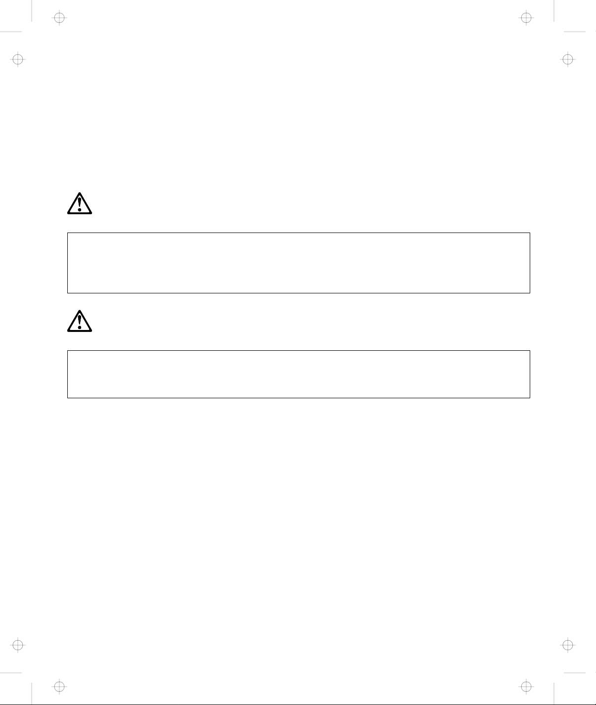
DANGER:
Electrical current from pow er, telephone, and com munication
cables is hazardous. To avoid shock hazard, connect and
disconnect cables as shown below when installing, m oving or
opening the covers of this product or attached devices. The
power cord m ust be used w ith a properly-grounded outlet.
To Con n ect
Turn everything OFF.
To Disconnect
Turn everything OFF.
First, attach all cables to devices.
Attach signal cables to
receptacles.
Attach pow er cord to outlet.
Turn device ON .
Note: In the U.K., by law, the telephone
line cable must be connected after the
power cord.
First, remove power cord from
outlet.
Rem ove signal cables from
receptacles.
Rem ove all cables from devices.
Note: In the U.K., by law, the power
cord must be disconnected after the
te lep h o n e lin e c a b le .
v
Page 9

Title: C74AMST CreationDate: 06/23/93 17:09:07
vi IBM ThinkPad Dock I User’s Guide
Page 10

Title: C74AMST CreationDate: 06/23/93 17:09:07
This manual contains the information that is needed when you use
the IBM* ThinkPad* Dock I (hereinafter referred to as the Dock I). It
is organized into the following chapters and appendixes:
About This Manual
Chapter 1, “Introduction” introduces the Dock I and describes
its features.
Chapter 2, “Using the Dock I” provides the procedures for
setting up the Dock I. Basic operations are also described.
Chapter 3, “Using the Security Features” describes the ways
you can protect your Dock I against unauthorized use.
Chapter 4, “Installing and Removing IBM Options” describes
how to install IBM options using both the documentation
provided with the option and this documentation.
Chapter 5, “Using the SCSI Controller and Support Software”
provides information about the setup of the SCSI controller’s
configuration, the installation of the option device drivers, and
the SCSI diagnostics utility program.
Chapter 6, “Solving Problems” describes how you can detect
and resolve Dock I problems.
Appendix A, “Starting up the OS from the Dock I” describes a
way to start up an operating system that resides on a device
attached to the Dock I.
Appendix B, “SCSI Information” provides information about
SCSI device ordering, connectors, termination, and cable lengths.
Appendix C, “Using the Selectable Program Load” shows how
to automatically load application programs into the memory of
the computer that enable the options installed in the Dock I
when only the computer is attached.
Appendix D, “Specifications” describes the specifications
associated with your Dock I, the power cords, and the ports.
Appendix E, “Product Warranties, Notices, and Statements”
contains the warranty statement of the Dock I, notices,
*
Trademark of the International Business Machines Corporation.
Copyright IBM Corp. 1993
vii
Page 11

Title: C74AMST CreationDate: 06/23/93 17:09:07
trademarks, service marks, FCC statement, CDCC statement,
and EC directive conformance statement.
viii IBM ThinkPad Dock I User’s Guide
Page 12

Title: C74AMST CreationDate: 06/23/93 17:09:07
Electrical Safety Notice ......................... iii
About This Manual ........................... vii
Chapter 1. Introduction . . . . . . . . . . . . . . . . . . . . . . . 1-1
Checking the Items .......................... 1-3
Locating Dock I Features ....................... 1-4
Dock I Status Indicators ....................... 1-9
Changing Modes . . . . . . . . . . . . . . . . . . . . . . . . . . . . 1-11
Warning Function . . . . . . . . . . . . . . . . . . . . . . . . . . . 1-12
Contents
Front View . . . . . . . . . . . . . . . . . . . . . . . . . . . . . . 1-4
Rear View . . . . . . . . . . . . . . . . . . . . . . . . . . . . . . 1-6
Rules of Attachment and Removal ............... 1-12
Attaching the Computer to the Dock I ............. 1-12
Removing the Computer from the Dock I ........... 1-14
Chapter 2. Using the Dock I .................... 2-1
Setting Up the Dock I ......................... 2-2
Attaching and Removing the Computer .............. 2-3
Attaching the Computer ..................... 2-3
Removing the Computer ..................... 2-10
Using the Display Stand ....................... 2-13
Carrying the Dock I with the Computer Attached ........ 2-14
Chapter 3. Using the Security Features ............. 3-1
Using the Security Lock ....................... 3-2
Security Lock Description ..................... 3-2
Key Positions and Their Functions ............... 3-2
Securing the Dock I with the Security Hook ........... 3-4
Ordering Additional Security Lock Keys ............ 3-5
Chapter 4. Installing and Removing IBM Options ...... 4-1
Handling Internal Options ...................... 4-2
Removing and Installing the Bottom Cover ............ 4-3
Removing the Bottom Cover ................... 4-3
Installing the Bottom Cover ................... 4-5
Removing and Installing the Blank Bezel ............. 4-7
Removing the Blank Bezel .................... 4-8
Installing the Blank Bezel ..................... 4-9
Releasing the Latches ......................... 4-10
Copyright IBM Corp. 1993 ix
Page 13

Title: C74AMST CreationDate: 06/23/93 17:09:07
Installing and Removing the Internal CD-ROM Drive ..... 4-11
Installing the Internal CD-ROM Drive ............. 4-11
Removing the Internal CD-ROM Drive ............. 4-13
Installing and Removing the Internal SCSI Hard Disk ..... 4-14
Installing the Internal SCSI Hard Disk ............. 4-14
Removing the Internal SCSI Hard Disk ............ 4-16
Installing and Removing the ThinkPad Hard Disk Drive ... 4-17
Installing the ThinkPad Hard Disk Drive ........... 4-17
Removing the ThinkPad Hard Disk Drive. .......... 4-18
Installing and Removing the Audio Cable ............ 4-19
Installing the Audio Cable .................... 4-19
Removing the Audio Cable .................... 4-21
Installing and Removing an Adapter Card ............ 4-22
Installing an Adapter Card .................... 4-22
Removing the Adapter Card ................... 4-23
Chapter 5. Using the SCSI Controller and Support Software 5-1
Setting up the SCSI Controller Configuration .......... 5-3
Default Settings . . . . . . . . . . . . . . . . . . . . . . . . . . . 5-3
SCSI Controller’s Memory Address Settings .......... 5-5
SCSI Controller’s Interrupt Settings ............... 5-5
SCSI ID . . . . . . . . . . . . . . . . . . . . . . . . . . . . . . . . 5-6
Terminator for a SCSI Device .................. 5-7
Checking Your Work ......................... 5-8
Installing Support Software ..................... 5-9
Before You Begin .......................... 5-9
Special Considerations . . . . . . . . . . . . . . . . . . . . . . . 5-9
Installing the DOS Device Drivers ............... 5-9
Installation Procedure . . . . . . . . . . . . . . . . . . . . . 5-9
Installing the OS/2 Device Drivers ............... 5-14
SCSI Adapter Support Installation for the Dock I ..... 5-14
SCSI Device Support Installation ............... 5-15
Installing the OS/2 Version 2.1 CD-ROM Device Driver 5-18
Using the SCSI Diagnostics Utility ................. 5-20
Preparing SCSI Drives ..................... 5-20
Starting the SCSI Diagnostics Utility .............. 5-21
Chapter 6. Solving Problems . . . . . . . . . . . . . . . . . . . 6-1
Before the Testing Is Started ..................... 6-3
Testing Your Dock I .......................... 6-5
x IBM ThinkPad Dock I User’s Guide
Page 14

Title: C74AMST CreationDate: 06/23/93 17:09:07
Troubleshooting Charts . . . . . . . . . . . . . . . . . . . . . . . . 6-7
Computer Keyboard Problems .................. 6-7
External Display (CRT) Problems ................ 6-8
External Keyboard, External Numeric Keypad, or Pointing
Device Problems . . . . . . . . . . . . . . . . . . . . . . . . . 6-10
Intermittent Problems . . . . . . . . . . . . . . . . . . . . . . . 6-12
LCD Problems . . . . . . . . . . . . . . . . . . . . . . . . . . . 6-12
Option Problems . . . . . . . . . . . . . . . . . . . . . . . . . . 6-14
Printer Problems . . . . . . . . . . . . . . . . . . . . . . . . . . 6-15
Screen Messages . . . . . . . . . . . . . . . . . . . . . . . . . . 6-15
Other Problems . . . . . . . . . . . . . . . . . . . . . . . . . . . 6-15
Getting Service . . . . . . . . . . . . . . . . . . . . . . . . . . . . . 6-17
Appendix A. Starting up the OS from the Dock I ...... A-1
Planning for the Operating System Startup ............ A-2
Starting DOS . . . . . . . . . . . . . . . . . . . . . . . . . . . . . . A-4
Starting OS/2 2.1 from the Additional Hard Disk ........ A-8
Appendix B. SCSI Information . . . . . . . . . . . . . . . . . . B-1
Device Ordering and the Boot Drive ................ B-2
External SCSI Connector ....................... B-2
Internal SCSI Connector ....................... B-3
Termination . . . . . . . . . . . . . . . . . . . . . . . . . . . . . . . B-4
SCSI Cable Length Specifications .................. B-4
Appendix C. Using the Selectable Program Load ....... C-1
Appendix D. Specifications . . . . . . . . . . . . . . . . . . . . D-1
Physical Characteristics . . . . . . . . . . . . . . . . . . . . . . . . D-1
Environment Requirements . . . . . . . . . . . . . . . . . . . . . D-1
Temperature, Relative Humidity, and Wet Bulb Temperature D-1
Maximum Altitude . . . . . . . . . . . . . . . . . . . . . . . . . D-1
Electrical Characteristics . . . . . . . . . . . . . . . . . . . . . . . D-2
Audio-Circuit Specifications . . . . . . . . . . . . . . . . . . . . . D-2
Speaker-In to Audio-Out ..................... D-2
Speaker-In to Headphone Jack .................. D-2
Speaker-In to Embedded Speaker ................ D-3
IBM Power Cords ........................... D-3
Appendix E. Product Warranties, Notices, and Statements . E-1
Contents xi
Page 15

Title: C74AMST CreationDate: 06/23/93 17:09:07
Notices . . . . . . . . . . . . . . . . . . . . . . . . . . . . . . . . . E-5
Trademarks and Service Marks ................... E-5
Federal Communications Commission (FCC) Statement .... E-6
Canadian Department of Communications Compliance
Statement . . . . . . . . . . . . . . . . . . . . . . . . . . . . . . . E-6
Avis de conformité aux normes du ministère des
Communications du Canada .................... E-6
European Community (EC) Directive Conformance Statement E-7
Index . . . . . . . . . . . . . . . . . . . . . . . . . . . . . . . . . . X-1
xii IBM ThinkPad Dock I User’s Guide
Page 16

Title: C74AMST CreationDate: 06/23/93 17:09:07
The Dock I provides expandability for your IBM ThinkPad notebook
models (hereinafter referred to as the computer), while providing the
same usability as a desktop computer system. Option cables
connected or disconnected to your computer can be connected to the
Dock I so you can easily carry your computer.
Because the Dock I is designed to be both multimedia-oriented and
portable, for example, you can give presentations at a customer’s
office more effectively with the full-motion images and stereo sound
of multimedia material.
The Dock I has enhanced security features to protect it from being
used by unauthorized persons.
The following summarizes the standard features or options on the
Dock I.
Chapter 1. Introduction
Multimedia-Oriented
Features
Portable-Oriented
Features
Cable Management
Features
Audio and
Video
Warning function to tolerate most of the inadvertent
miss-operations when docking and undocking the computer.
Handle
Security lock
Security hook
An external diskette drive connector
A keyboard/numeric keypad connector
A mouse/pointing device connector
A parallel connector
A serial connector
Speaker-in jacks
Audio-out jacks
A Headphone jack
Stereo speakers
A less than 1-inch-high drive location for a
CD-ROM player
Copyright IBM Corp. 1993 1-1
Page 17

Title: C74AMST CreationDate: 06/23/93 17:09:07
Desktop-Equivalent
Features
One full-size or half-size, AT-bus 16-bit slot
A less than 1-inch-high drive location for an internal storage
device
An internal and external SCSI device connectors
1-2 IBM ThinkPad Dock I User’s Guide
Page 18
Title: C74AMST CreationDate: 06/23/93 17:09:07
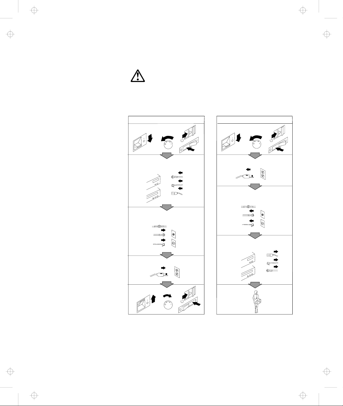
Checking the Items
Dock I Manual
Check that you have the following items.
If any are missing or damaged, call your IBM marketing
representative or dealer.
Option Diskette Power Cord
Security Lock Keys
Notes
1. An extra key is provided as a spare.
2. The key number is necessary when replacing lost keys. See
“Ordering Additional Security Lock Keys” on page 3-5.
Chapter 1. Introduction 1-3
Page 19
Title: C74AMST CreationDate: 06/23/93 17:09:07
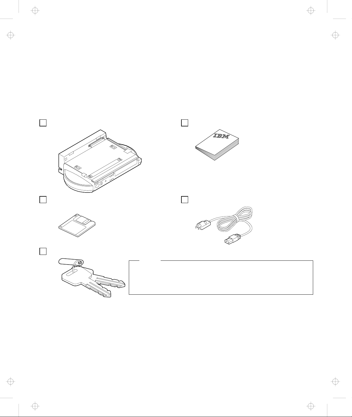
Locating Dock I Features
This section identifies the features for the Dock I. Symbols for
connectors are embossed on the back of the Dock I above each
connector for easy identification.
Front View
Name of Feature Description
1 Guide Pins The guide pins are used as guides when attaching the computer.
There are the matching alignment holes on the computer.
2 Docking
Connector
3 Lever Cover This cover is used to prevent the locking lever on the computer from
4 Right Speaker
5 Handle This handle is used when carrying the Dock I for short distances in
The docking connector (male-type, 240-pin) fits into the system
expansion connector.
being slid inward; the hard disk drive is removed from the computer
when the lever is slid inward. This cover also be used as a handhold
with the docking-knob 13 when attaching the computer to the Dock
I.
an indoor environment.
1-4 IBM ThinkPad Dock I User’s Guide
Page 20

Title: C74AMST CreationDate: 06/23/93 17:09:07
Name of Feature Description
6 Location for less
than 1-inch-High
The Dock I can accommodate one storage device here. The blank
bezel is removed when installing an internal option.
Drive
7 Status Indicators The status indicators are LEDs (light-emitting diode) that indicate the
current status of the Dock I by their On/Off states. Each status
indicator has a matching special symbol below it.
For more information about the status indicators, see “Dock I Status
Indicators” on page 1-9.
8 Headphone Jack The headphone jack is where the plug of the stereo headphone is
connected.
Headphone or Speakers
When the stereo headphone plug is connected to this jack, the
speakers do not operate.
9 Release/Lock
Lever
When the release/lock lever protrudes from the Dock I, snapping it
closed secures the computer by engaging the computer with the
hooks 14 . Sliding the slide-knob 11 to the left snaps the
release/lock lever open.
1 Security Lock The security lock is used to secure different features on the Dock I,
depending on the position of the key. This prevents the bottom cover
of the Dock I from being removed, prevents unauthorized persons
from using the Dock I by securing the power, and prevents the
computer from being removed from the Dock I. (For more
information, see “Using the Security Lock” on page 3-2.)
11 Slide-Knob Sliding this knob to the left snaps the release/lock lever open.
12 Left Speaker
13 Docking-Knob This knob is as a finger-hold with the lever cover 3 when attaching
the computer to the Dock I.
14 Hooks Snapping the release/lock lever 9 closed engages the computer
with the hooks.
Chapter 1. Introduction 1-5
Page 21
Title: C74AMST CreationDate: 06/23/93 17:09:07
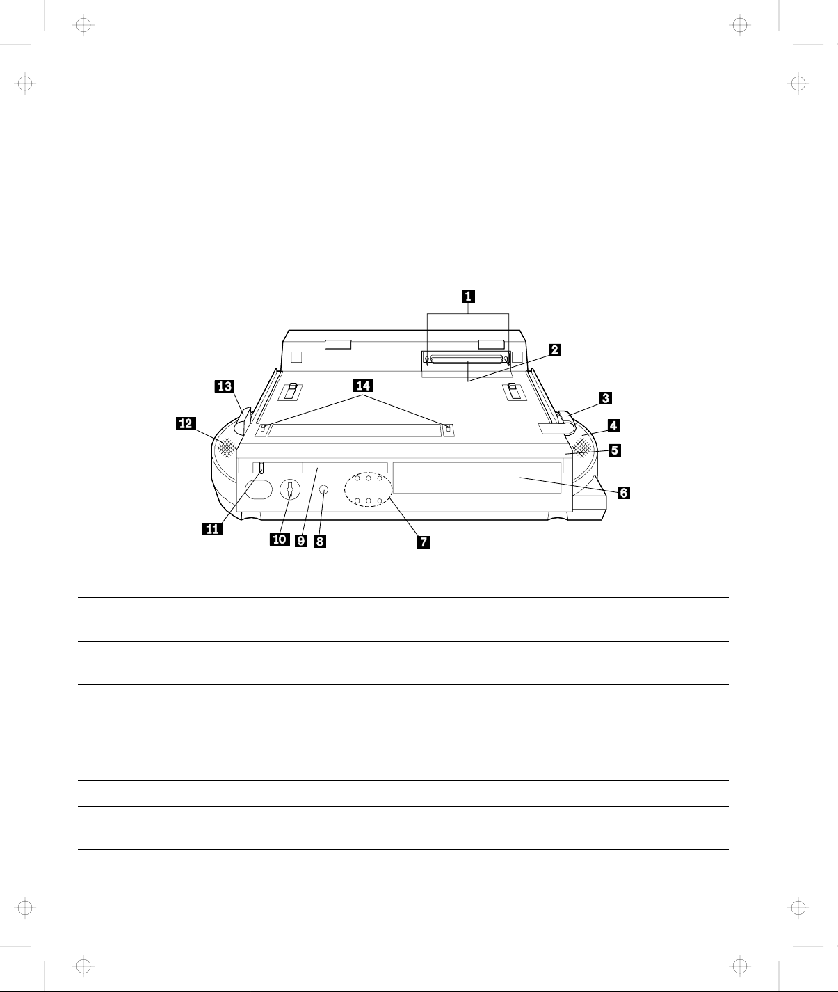
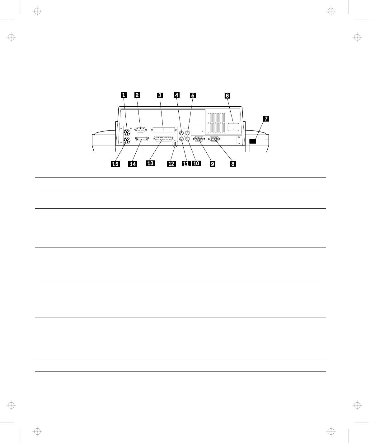
Rear View
Name of Feature Description
1 Mouse/Pointing
Device Connector
2 Serial Connector The serial connector (9-pin) usually connects a modem or
3 External SCSI
Connector
4 Audio-Out-Left
Jack
5 Speaker-In-Left
Jack
6 Power Cord
Connector
7 Cable Opening Used to route a cable from inside the Dock I without a slack.
The mouse/pointing device connector (6-pin) connects a mouse or
other pointing device cable.
serial-printer signal cable.
The external SCSI connector (60-pin) connects an external SCSI (small
computer system interface) device cable.
The audio-out-left jack (left-output sound, 2-pin) connects the
audio-out-left plug of the audio cable. For stereo speaker sound of
multimedia on external stereo speakers, use this jack with the
audio-out-right jack 11 through an amplifier.
The speaker-in-left jack (left-input sound, 2-pin) connects the
speaker-in-left plug of the audio cable. Use this jack with the
speaker-in-right jack 1 for stereo speaker sound of multimedia on
the Dock I.
The power cord connector connects the power cord. Power is
supplied to the Dock I and the computer. The battery pack inside the
computer is charged at the same time. Because the Dock I does not
have a power switch, power for it is controlled by the power switch
on the computer.
1-6 IBM ThinkPad Dock I User’s Guide
Page 22
Title: C74AMST CreationDate: 06/23/93 17:09:07
Name of Feature Description
8 Video-In
Connector
The video-in connector (15-pin) is used to view video images of
multimedia on the TFT LCD of the computer.
CAUTION:
The removable cap prevents damage to the pins of the external
display signal cable connector if it is inadvertently connected.
9 External Display
Connector
The external display connector (15-pin) connects the display signal
cable of the external display that supports Video Graphics Array
(VGA) of 640 by 480 resolution and Super VGA (SVGA) of 1024 by
768 resolution.
CAUTION:
Do not connect the external display signal cable connector to the
video-in connector 8 .
1 Speaker-In-Right
Jack
The speaker-in-right jack (right-input sound, 2-pin) connects the
speaker-in-right plug of the audio cable. Use this jack with the
speaker-in-left jack 5 for stereo speaker sound of multimedia on the
Dock I.
11 Audio-Out-Right
Jack
The audio-out-right jack (right-output sound, 2-pin) connects the
audio-out-right plug of the audio cable. For stereo speaker sound of
multimedia on external stereo speakers, use this jack with the
audio-in-left jack 4 through an amplifier.
12 Security Hook The security hook secures the Dock I. For more information, see
“Securing the Dock I with the Security Hook” on page 3-4.
13 Parallel
This parallel connector (25-pin) connects a printer signal cable.
Connector
Chapter 1. Introduction 1-7
Page 23

Title: C74AMST CreationDate: 06/23/93 17:09:07
Name of Feature Description
14 External Diskette
Drive Connector
(26-pin)
15 Keyboard/Numeric
Keypad
Connector
Connects the 3.5-inch diskette drive that has been removed from the
computer and set up with the IBM ThinkPad 750 FDD External
Attachment Kit (an IBM option).
The keyboard/numeric keypad connector (6-pin) connects the
keyboard or numeric keypad cable.
Important
1. Use this connector if you use an external keyboard or a
numeric keypad.
2. The keyboard (numeric keypad) on the computer cannot be
used when the external keyboard (external numeric keypad) is
attached through this connector.
3. You cannot connect a mouse or other pointing device to a
external numeric keypad that is connected to this connector.
Connect the mouse or other pointing device directly to the
mouse/pointing device connector 1 .
1-8 IBM ThinkPad Dock I User’s Guide
Page 24
Title: C74AMST CreationDate: 06/23/93 17:09:07
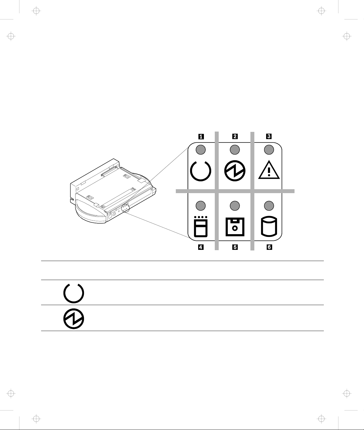
Dock I Status Indicators
The LED status indicators indicate the current status of the Dock I
by their On/Off states or their colors (green and orange). Each LED
indicator has a matching special symbol below it.
The following figure and table show the name, color, and meaning
of each LED indicator.
Symbol
1 Docked Green Turns on when the computer has been correctly
2 Power-On Green Turns on when the Dock I power is turned on using
Chapter 1. Introduction 1-9
Name of LED
Indicator
LED
Color
Meaning
docked with the Dock I.
the power switch on the computer.
Page 25
Title: C74AMST CreationDate: 06/23/93 17:09:07
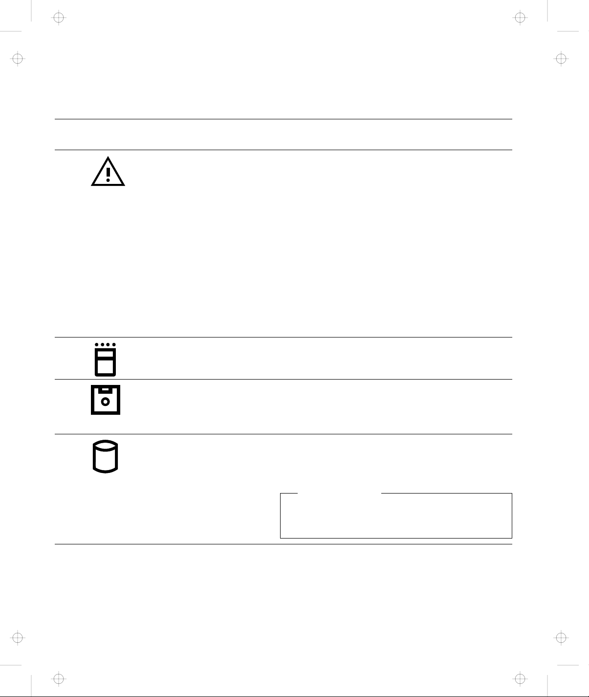
Symbol
Name of LED
Indicator
LED
Color
Meaning
3 Warning Orange Turns on or blinks when you attempt any of the
following operations. This LED warns you not to
continue the operation. For what happens if you
continue the operation, see “Warning Function” on
page 1-12.
Removing a computer that is working with a
Dock I.
Removing a computer that is in suspend mode
with a Dock I.
Removing a computer that is in standby mode
with a Dock I.
Attaching a computer that is in suspend mode
to a Dock I.
4 PC Card In-Use Orange Turns on when an inserted PC card (PCMCIA card)
is accessed.
5 Diskette Drive
In-Use
Orange Turns on when the diskette drive in the computer is
used. When an external diskette drive is used, the
indicator on the IBM ThinkPad 750 FDD External
Attachment Kit turns on.
6 Hard Disk In-Use Orange Turns on when either of the following is accessed.
The ThinkPad hard disk drive in the computer.
The ThinkPad hard disk drive in the Dock I.
SCSI Hard Disk
This indicator does not turn on when a SCSI
hard disk is accessed.
1-10 IBM ThinkPad Dock I User’s Guide
Page 26

Title: C74AMST CreationDate: 06/23/93 17:09:07
Changing Modes
When you are operating a computer that has been attached to the
Dock I, you cannot put the computer in hibernation mode. You will
hear a warning beep from the computer if you attempt this.
However, you can enter suspend and standby modes. The
following table summarizes these conditions.
Attempt to Enter Can the Computer Enter the Mode? Is a Password Needed?
Suspend Mode Yes Power-on password if you
have set one. The password
prompt and cursor do not
appear.
Standby Mode Yes None
Hibernation Mode No None
Chapter 1. Introduction 1-11
Page 27

Title: C74AMST CreationDate: 06/23/93 17:09:07
Warning Function
When computer power is turned off, attaching or removing the
computer to or from the Dock I causes no problems. Make sure that
if you attach or remove the computer to or from the Dock I you
observe the following rules.
Rules of Attachment and Removal
Rules of Attachment Rules of Removal
1. Return to operating mode.
2. Shut down the
application.
3. Turn off the computer.
4. Attach the computer to
the Dock I.
When computer power is on, attaching or removing the computer,
or changing the operation mode can cause a problem. The Dock I
informs you with a beep and a warning indicator that you should
stop the operation. The following explains this warning function.
Attaching the Computer to the Dock I
Do not attach the computer to the Dock I when:
An application is running on the computer.
The computer has entered standby mode.
The computer has entered suspend mode.
The computer has entered hibernation mode.
The following table shows what will occur.
1. Return to operating mode.
2. Shut down the
application.
3. Turn off the computer.
4. Remove the computer
from the Dock I.
1-12 IBM ThinkPad Dock I User’s Guide
Page 28

Title: C74AMST CreationDate: 06/23/93 17:09:07
Current Status This Will Occur
An application is running on
the computer.
The computer has entered
standby mode.
The computer has entered
suspend mode.
The computer has entered
hibernation mode.
These operations are not allowed.
This operation may cause all application memory-related data to
be lost even though you stop the attachment in the middle of
the operation.
Power Is Turned Off
This operation turns off the power of the computer and the
Dock I.
This operation is not allowed.
The Dock I warning indicator turns on and a warning beep
sounds.
Cannot Resume
You cannot resume the operation unless you stop and attach
the computer immediately.
This operation is not allowed.
When the computer is turned on, a warning screen appears. In
this case, do the following.
1. Turn off the the computer.
2. Remove the computer from the Dock I
3. Resume operating mode.
4. Shut down the application.
5. Turn off the computer.
6. Attach the computer to the Dock I
Chapter 1. Introduction 1-13
Page 29
Title: C74AMST CreationDate: 06/23/93 17:09:07
Removing the Computer from the Dock I
Do not remove the computer from the Dock I when the computer is
in one of the following modes:
Operating mode
Standby mode
Suspend mode
When the computer is in one of these modes and you inadvertently
move the slide-knob, the release/lock lever snaps open 1 , the
warning indicator blinks, and the warning beep sounds 2 .
To recover immediately snap, the release/lock lever closed 3 . The
computer stays in the same mode before you moved the slide-knob.
The following table summarizes the correct operation.
If you slide the slide-knob...
1
2 The warning indicator continues to
blink.
2 The warning beep continues to
sound.
Snap the release/lock
lever closed.
3
1-14 IBM ThinkPad Dock I User’s Guide
Page 30

Title: C74AMST CreationDate: 06/23/93 17:09:07
Warning: Computer and Dock I power will turn off if you pull the
release/lock lever any further after the warning beep is heard and
the warning indicator blinks. All application memory-related data
may be lost.
Chapter 1. Introduction 1-15
Page 31

Title: C74AMST CreationDate: 06/23/93 17:09:07
1-16 IBM ThinkPad Dock I User’s Guide
Page 32

Title: C74AMST CreationDate: 06/23/93 17:09:07
This chapter contains the procedures for the initial and basic
operations when using the Dock I.
This chapter contains:
Setting Up the Dock I ......................... 2-2
Attaching and Removing the Computer .............. 2-3
Using the Display Stand ....................... 2-13
Carrying the Dock I with the Computer Attached ........ 2-14
Chapter 2. Using the Dock I
Attaching the Computer ..................... 2-3
Removing the Computer ..................... 2-10
Copyright IBM Corp. 1993 2-1
Page 33

Title: C74AMST CreationDate: 06/23/93 17:09:07
Setting Up the Dock I
Before you attach the computer to the Dock I, do the following.
To install the internal CD-ROM drive: Go to “Installing and Removing the
To install the internal SCSI hard disk: Go to “Installing and Removing the
To install the ThinkPad hard disk drive: Go to “Installing and Removing the
To install the audio cable: Go to “Installing and Removing the
To install an adapter card: Go to “Installing and Removing an
Internal CD-ROM Drive” on page 4-11.
Internal SCSI Hard Disk” on page 4-14.
ThinkPad Hard Disk Drive” on
page 4-17.
Audio Cable” on page 4-19.
Adapter Card” on page 4-22.
To calculate the SCSI cable length: Go to “SCSI Cable Length Specifications”
on page B-4.
If you have nothing to install or have
finished installing all options:
Go to “Attaching and Removing the
Computer” on page 2-3.
2-2 IBM ThinkPad Dock I User’s Guide
Page 34

Title: C74AMST CreationDate: 06/23/93 17:09:07
Attaching and Removing the Computer
CAUTION:
Do not operate the Dock I with the bottom cover removed. To
install the bottom cover, see “Installing the Bottom Cover” on
page 4-5.
This section describes the procedures for attaching and removing
the computer to and from the Dock I.
Attaching the Computer
To attach the computer to the Dock I, do the following:
1.
See “Rules of Attachment and
Removal” on page 1-12.
2.
Make sure:
Your computer is turned off.
The LCD of your computer
is closed.
All cables of your computer
are disconnected.
3.
Plug the power cord into the
power cord connector of the
Dock I.
See page 1-6 for the location of the power cord connector.
Chapter 2. Using the Dock I 2-3
Page 35

Title: C74AMST CreationDate: 06/23/93 17:09:07
4.
Unlock the security lock on the
front of the Dock I by turning
the key to the middle position.
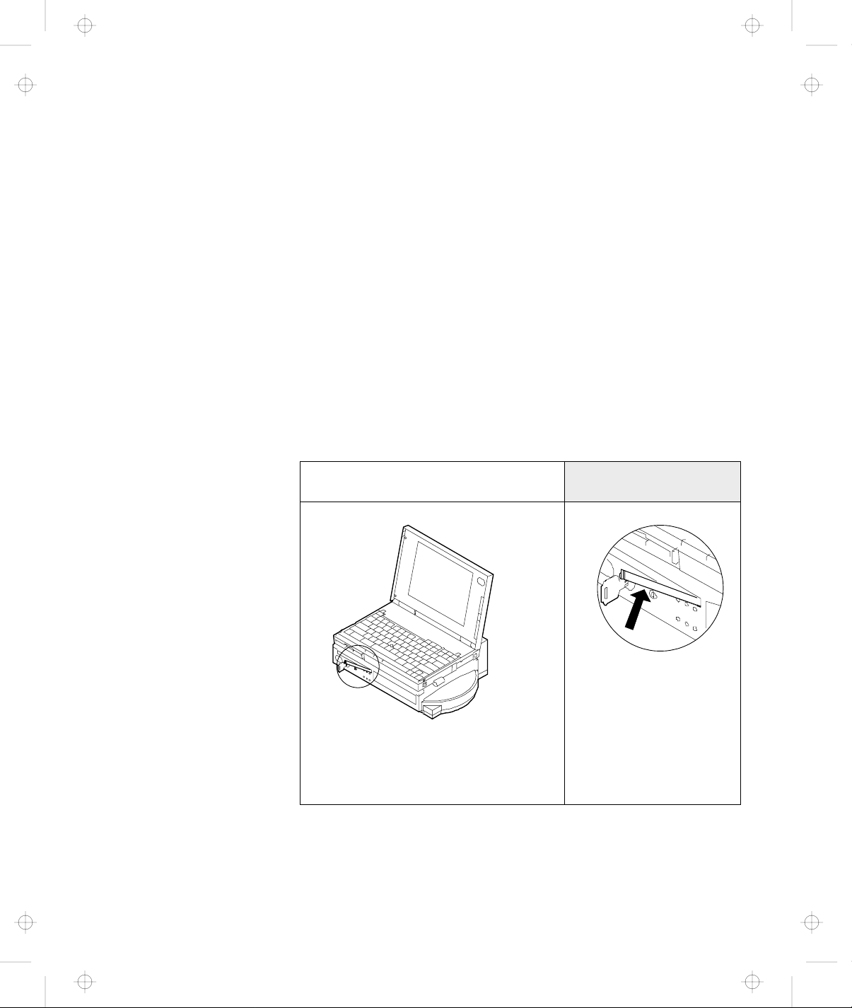
5.
Slide and open the door 1 on
the rear of the computer.
When you have removed the
computer, close the door.
2-4 IBM ThinkPad Dock I User’s Guide
Page 36

Title: C74AMST CreationDate: 06/23/93 17:09:07
6.
Important
Handle the computer
gently; the hard disk is
very shock-sensitive.
Turn the computer upside down.
Slide the locking lever 1 on
the bottom of your computer
outward.
This is done to make sure that the
hard disk inside the computer
cannot be removed.
When you have removed the
computer, slide the locking
lever inward.
Chapter 2. Using the Dock I 2-5
Page 37

Title: C74AMST CreationDate: 06/23/93 17:09:07
7.
Look at the Dock I. If the hooks
1 are raised as shown, you
cannot attach the computer.
Move the slide-knob 2 to the
left.
The hooks 3 are lowered and
the release/lock lever 4 snaps
open.
2-6 IBM ThinkPad Dock I User’s Guide
Page 38

Title: C74AMST CreationDate: 06/23/93 17:09:07
8.
Important
Wait at least ten
seconds before you
re-attach the
computer after it has
been removed.
Handle the
computer gently; the
hard disk is very
shock-sensitive.
Place the computer on top of
the Dock I and slide the
computer in until the guide pins
1 fit into the alignment holes
6 .
Use both the docking-knob 7
and the lever cover 2 as
finger-holds so that the docking
connector 5 fits firmly into the
system expansion connector 4 .
Note
If the computer is turned off,
you can install it with its
display (LCD) opened.
Chapter 2. Using the Dock I 2-7
Page 39

Title: C74AMST CreationDate: 06/23/93 17:09:07
9.
Snap the release/lock lever 1
closed.
Notes
1. Sound from the cooling
fan inside the Dock I is
normal.
2. When the computer is
installed correctly, the
docked indicator turns
on and stays on.
10.
Lock the security lock on the
front of the Dock I by turning
the key to the extreme right
position.
Remove the key and keep it in a
safe place.
2-8 IBM ThinkPad Dock I User’s Guide
Page 40

Title: C74AMST CreationDate: 06/23/93 17:09:07
11.
Open the LCD of the computer,
turn on all external devices,
then turn on the computer.
Notes
1. If the warning beep
sounds and the warning
indicator blinks, make
sure that the
release/lock lever is
locked. See step 9 on
page 2-8.
2. The Dock I is not
equipped with a power
switch. The power
switch of the computer
turns on and off the
power of itself and the
Dock I. If the battery
pack is installed in the
computer, charging of
the battery pack starts
automatically.
You can now use the computer.
Chapter 2. Using the Dock I 2-9
Page 41

Title: C74AMST CreationDate: 06/23/93 17:09:07
Removing the Computer
1.
See “Rules of Attachment and
Removal” on page 1-12.
2.
Shut down the application
program. Turn off the
computer; this also turns off the
Dock I. Close the LCD of the
computer.
To remove the computer from the Dock I, do the following:
3.
Unlock the security lock on the
front of the Dock I by turning
the key to the middle position.
4.
Slide the slide-knob to the left.
Refer to step 7 on page 2-6.
2-10 IBM ThinkPad Dock I User’s Guide
Page 42

Title: C74AMST CreationDate: 06/23/93 17:09:07
5.
Pull the release/lock lever 1
until it stops.
6.
Important
Handle the computer
gently; the hard disk is
very shock-sensitive.
Remove the computer from the
Dock I.
Chapter 2. Using the Dock I 2-11
Page 43

Title: C74AMST CreationDate: 06/23/93 17:09:07
7.
To prevent unauthorized
persons from using your Dock I,
lock the security lock on the
front of the Dock I by turning
the key to the extreme left
position.
Remove the key and keep it in a
safe place.
Key Positions
The key positions and their
functions are explained in
“Key Positions and Their
Functions” on page 3-2.
You have completed the removal of the computer from the Dock I.
Where to Go Next
Installation of the operating system on an additional hard
disk: page A-1
Display stand: page 2-13
Security hook: page 3-4
2-12 IBM ThinkPad Dock I User’s Guide
Page 44

Title: C74AMST CreationDate: 06/23/93 17:09:07
Using the Display Stand
The display stand is available as an IBM option. You can use the
display stand separately from the Dock I.
If you are going to view the screen when the external display is on
the display stand and are going to type on the keyboard of the
notebook computer, open the LCD at an angle of 180 degrees and
keep it out of the way under the display stand.
Chapter 2. Using the Dock I 2-13
Page 45
Title: C74AMST CreationDate: 06/23/93 17:09:07
Carrying the Dock I with the Computer Attached
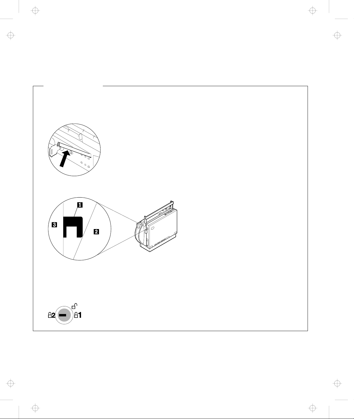
Correctly Attached?
Before you carry the Dock I with the computer attached, make sure that:
1. The release/lock lever is locked.
If it is not locked, the computer could separate from the Dock I.
2. The computer (represented by 2 ) is not attached to the Dock I (represented by 3 ) with the
hooks 1 as shown.
If it is attached in this manner, do the following.
a. Remove the computer by referring to “Removing the Computer” on page 2-10.
b. Re-attach the computer by referring to “Attaching the Computer” on page 2-3.
3. The security lock key is turned to the following position and the key is removed.
The handle in the Dock I can be used to carry the Dock I or carry
the Dock I with the computer attached for short distances.
2-14 IBM ThinkPad Dock I User’s Guide
Page 46

Title: C74AMST CreationDate: 06/23/93 17:09:07
When you carry the Dock I with the computer attached for longer
distances, use the carrying case. The carrying case is available as an
IBM accessory.
The handle can be used as a palm rest when you operate the
computer.
Note: If you are going to use the computer keyboard with the Dock
I attached for more than 30 minutes continuously or more
than a total of one hour a day, appropriately adjust the height
of the system or use an external keyboard.
Chapter 2. Using the Dock I 2-15
Page 47

Title: C74AMST CreationDate: 06/23/93 17:09:07
2-16 IBM ThinkPad Dock I User’s Guide
Page 48

Title: C74AMST CreationDate: 06/23/93 17:09:07
This chapter contains information on how you can protect your
Dock I against theft or unauthorized use. There are two ways to
secure the Dock I; use the security lock or attach the it to a work
surface.
This chapter contains:
Using the Security Lock ....................... 3-2
Securing the Dock I with the Security Hook ........... 3-4
Chapter 3. Using the Security Features
Security Lock Description ..................... 3-2
Key Positions and Their Functions ............... 3-2
Ordering Additional Security Lock Keys ............ 3-5
Copyright IBM Corp. 1993 3-1
Page 49

Title: C74AMST CreationDate: 06/23/93 17:09:07
Using the Security Lock
You can secure the Dock I and the computer by using the security
lock on the front of the Dock I. The following describes the security
lock and shows the various ways to use it.
Security Lock Description
The security lock secures the following:
Bottom Cover When the bottom cover is locked by the security lock, the bottom cover cannot be
removed to protect options installed in the Dock I.
Computer The computer cannot be removed when the key position is Lock 1 or Lock 2.
When you attach or remove the computer to or from the Dock I, set the key
position to Unlock. For the key positions, see “Key Positions and Their
Functions.”
Power The Dock I power cannot be turned on when the power is locked by the security
lock.
Key Positions and Their Functions
The following shows the key positions of the security lock and their
corresponding functions.
3-2 IBM ThinkPad Dock I User’s Guide
Page 50

Title: C74AMST CreationDate: 06/23/93 17:09:07
Key Position Explanation Can the
Bottom
Cover Be
Removed?
Unlock Turn to this position
Yes Yes (On or Off). No
to remove the
bottom cover.
Lock 1 The key is turned to
No Yes (On or Off). Yes
this position when
the Dock I is used.
Lock 2 The key is turned to
No Cannot be turned on after
this position to
prevent
unauthorized
persons from
turning on and
using the Dock I.
Can the Dock I Power Be
Turned On or Off?
the Dock I is turned off.
Note
To turn on the Dock I,
turn the key to the
extreme right position.
Can the
Key Be
Removed?
Yes
Chapter 3. Using the Security Features 3-3
Page 51

Title: C74AMST CreationDate: 06/23/93 17:09:07
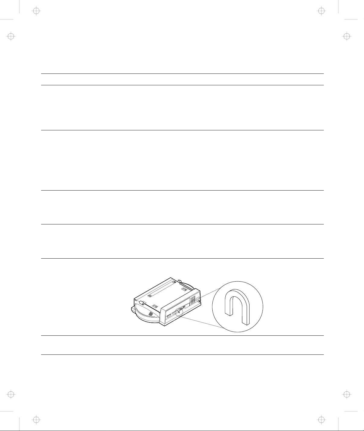
Securing the Dock I with the Security Hook
You can secure the Dock I to a
table or desk by routing a chain
or cable through the security
hook at the rear of the Dock I.
Note
You must purchase the chain
or cable and lock. The
diameter of the chain or
cable must be approximately
4 mm (0.15 in.) or less.
3-4 IBM ThinkPad Dock I User’s Guide
Page 52

Title: C74AMST CreationDate: 06/23/93 17:09:07
Ordering Additional Security Lock Keys
Information for ordering additional keys may be obtained by
writing to the address given on the tag attached to the keys. When
requesting additional keys, be sure to include the key number from
the tag. An additional charge is required.
The following information should be recorded. The key number is on
the tag that is attached to the keys.
IBM Product Name IBM ThinkPad Dock I
Key Number
Chapter 3. Using the Security Features 3-5
Page 53

Title: C74AMST CreationDate: 06/23/93 17:09:07
3-6 IBM ThinkPad Dock I User’s Guide
Page 54

Title: C74AMST CreationDate: 06/23/93 17:09:07
Chapter 4. Installing and Removing IBM Options
Options are devices that you can attach to or install inside the Dock
I to expand the capabilities of your computer. This chapter provides
the instructions to add internal options to your computer.
This chapter contains:
Handling Internal Options ...................... 4-2
Removing and Installing the Bottom Cover ............ 4-3
Removing and Installing the Blank Bezel ............. 4-7
Releasing the Latches ......................... 4-10
Installing and Removing the Internal CD-ROM Drive ..... 4-11
Installing and Removing the Internal SCSI Hard Disk ..... 4-14
Installing and Removing the ThinkPad Hard Disk Drive ... 4-17
Installing and Removing the Audio Cable ............ 4-19
Installing and Removing an Adapter Card ............ 4-22
Removing the Bottom Cover ................... 4-3
Installing the Bottom Cover ................... 4-5
Removing the Blank Bezel .................... 4-8
Installing the Blank Bezel ..................... 4-9
Installing the Internal CD-ROM Drive ............. 4-11
Removing the Internal CD-ROM Drive ............. 4-13
Installing the Internal SCSI Hard Disk ............. 4-14
Removing the Internal SCSI Hard Disk ............ 4-16
Installing the ThinkPad Hard Disk Drive ........... 4-17
Removing the ThinkPad Hard Disk Drive. .......... 4-18
Installing the Audio Cable .................... 4-19
Removing the Audio Cable .................... 4-21
Installing an Adapter Card .................... 4-22
Removing the Adapter Card ................... 4-23
Copyright IBM Corp. 1993 4-1
Page 55

Title: C74AMST CreationDate: 06/23/93 17:09:07
Handling Internal Options
Warning: Do not open the static-protective package containing the
option until you are instructed to install the option. Static electricity
can damage the option.
When you are instructed to install the option, observe these
precautions as you open the static-protective package:
Touch the static-protective package containing the option to a
metallic portion of the Dock I for at least 2 seconds. This action
reduces the static electricity from the package and from your
body.
Do not touch any exposed circuitry on the option.
Prevent other people from touching the option.
Limit your movement. Movement can cause static-electricity
buildup.
Always handle the option carefully and by its edges.
If you must put the option down after it has been removed from
the package, place the option on the static-protective package
on a level surface. Do not place the option on a metal table.
4-2 IBM ThinkPad Dock I User’s Guide
Page 56

Title: C74AMST CreationDate: 06/23/93 17:09:07
Removing and Installing the Bottom Cover
This section describes the procedures for removing and installing
the bottom cover of the Dock I.
Removing the Bottom Cover
To remove the bottom cover, do the following:
1.
Unlock the security lock on the
front of the Dock I by turning
the key to the middle position.
Move the slide-knob to the left.
(Refer to step 7 on page 2-6.)
2.
Turn the Dock I upside down
and place it on a book 5 as
shown. Unscrew the four
screws ( 1 2 3 4 ) using a
coin.
Chapter 4. Installing and Removing IBM Options 4-3
Page 57

Title: C74AMST CreationDate: 06/23/93 17:09:07
3.
Open the bottom cover. You
can remove the cable guide
cover 1 if a cable from inside
the Dock I cannot be routed
through the cable opening 2 .
You have completed the removal of the bottom cover.
4-4 IBM ThinkPad Dock I User’s Guide
Page 58

Title: C74AMST CreationDate: 06/23/93 17:09:07
Installing the Bottom Cover
To install the bottom cover, do the following:
1.
Install the cable guide cover 1
in the bottom cover if a cable
from inside the Dock I can be
routed through the cable
opening. Close the bottom
cover.
2.
Tighten the four screws ( 1 2
3 4 ) using a coin.
Chapter 4. Installing and Removing IBM Options 4-5
Page 59

Title: C74AMST CreationDate: 06/23/93 17:09:07
You have completed the installation of the bottom cover.
4-6 IBM ThinkPad Dock I User’s Guide
Page 60

Title: C74AMST CreationDate: 06/23/93 17:09:07
Removing and Installing the Blank Bezel
This section describes the procedures for removing and installing
the blank bezel 1 .
Chapter 4. Installing and Removing IBM Options 4-7
Page 61

Title: C74AMST CreationDate: 06/23/93 17:09:07
Removing the Blank Bezel
To remove the blank bezel, do the following:
1.
If you install an option in this
compartment, press the latches
2 of the blank bezel 1 at the
same time to remove it 3 .
2.
If you do not need to reinstall
the blank bezel 1 because of
an option, for example, the
internal CD-ROM drive, place
the blank bezel in the order of
2 and 3 .
If you need to reinstall the
blank bezel 1 because of an
option, for example, the internal
SCSI hard disk, perform step 1
in the reverse order.
You have completed the removal of the blank bezel.
4-8 IBM ThinkPad Dock I User’s Guide
Page 62

Title: C74AMST CreationDate: 06/23/93 17:09:07
Installing the Blank Bezel
To install the blank bezel, perform the installation procedure in the
reverse order.
Chapter 4. Installing and Removing IBM Options 4-9
Page 63

Title: C74AMST CreationDate: 06/23/93 17:09:07
Releasing the Latches
To release the latches for an internal storage device, press the left
and right latches ( 1 and 2 ) at the same time as shown.
4-10 IBM ThinkPad Dock I User’s Guide
Page 64

Title: C74AMST CreationDate: 06/23/93 17:09:07
Installing and Removing the Internal CD-ROM Drive
The Dock I can accommodate one internal CD-ROM drive.
This section describes the procedures for installing and removing
the internal CD-ROM drive.
CAUTION:
1. This CD-ROM drive uses a laser system. To ensure correct
use of this product, read the manual that came with the
CD-ROM drive carefully and keep the manual for future
reference. Should the unit ever require maintenance, contact
an authorized service location.
2. Use of controls, adjustments or the performance of procedure
other than those specified may result in hazardous radiation
exposure.
3. To prevent direct exposure to the laser beam, do not open the
enclosure.
Installing the Internal CD-ROM Drive
To install the CD-ROM drive in the Dock I, do the following:
1.
Remove the bottom cover.
2.
If you have installed an adapter
card, remove it.
3.
If the blank bezel is installed,
remove it.
See “Removing the Bottom Cover” on page 4-3.
See “Removing the Adapter Card” on page 4-23.
See “Removing the Blank Bezel” on page 4-8.
Chapter 4. Installing and Removing IBM Options 4-11
Page 65

Title: C74AMST CreationDate: 06/23/93 17:09:07
4.
Insert the connector 1 of the
flat-ribbon cable into the
connector 2 of the CD-ROM
drive.
5.
Note
If the audio connector 1
and the power connector 2
are fastened together with a
twist-tie, undo the twist-tie
and separate them.
Insert the CD-ROM drive into
the compartment 5 . Insert the
power connector 2 into the
connector 3 . Insert the audio
connector 1 into the connector
4 .
4-12 IBM ThinkPad Dock I User’s Guide
Page 66

Title: C74AMST CreationDate: 06/23/93 17:09:07
6.
Insert the CD-ROM in until it
stops 3 . Insert the connector
2 into the connector 1 .
Latches
If you need to remove the
CD-ROM, you must release
the latches. See “Releasing
the Latches” on page 4-10.
7.
See “Installing an Adapter Card” on page 4-22.
If you have removed an adapter
card, reinstall it.
8.
See “Installing the Bottom Cover” on page 4-5.
Install the bottom cover.
You have completed the installation of the internal CD-ROM drive in the
Dock I.
Removing the Internal CD-ROM Drive
To remove the internal CD-ROM drive, perform the installation
procedure in the reverse order.
Chapter 4. Installing and Removing IBM Options 4-13
Page 67

Title: C74AMST CreationDate: 06/23/93 17:09:07
Installing and Removing the Internal SCSI Hard Disk
The Dock I can accommodate one, under-1-inch-high internal SCSI
hard disk.
This section describes the procedures for installing and removing
the internal SCSI hard disk for the Dock I.
Installing the Internal SCSI Hard Disk
To install the internal SCSI hard disk in the Dock I, do the
following:
1.
Remove the bottom cover.
2.
If you have installed an adapter
card, remove it.
3.
If the blank bezel is installed,
remove it.
4.
Attach the internal SCSI hard
disk to the optional Internal
SCSI Device Installation Kit.
See “Removing the Bottom Cover” on page 4-3.
See “Removing the Adapter Card” on page 4-23.
See “Removing the Blank Bezel” on page 4-8.
Refer to the manual that came with the option.
4-14 IBM ThinkPad Dock I User’s Guide
Page 68

Title: C74AMST CreationDate: 06/23/93 17:09:07
5.
Note
If the power connector 2
and the other small
connector (not shown) are
fastened together with a
twist-tie, undo the twist-tie
and separate them.
Insert the SCSI hard disk into
the compartment 4 . Insert the
power connector 2 into the
connector 3 . Insert the
connector 5 into the connector
1 . Push the SCSI hard disk in
until it stops.
Latches
If you need to remove the
SCSI hard disk, you must
release the latches. See
“Releasing the Latches” on
page 4-10.
6.
See “Removing the Blank Bezel” on page 4-8.
Install the blank bezel. Perform
the removal procedure in the
reverse order.
7.
See “Installing an Adapter Card” on page 4-22.
If you have removed an adapter
card, reinstall it.
Chapter 4. Installing and Removing IBM Options 4-15
Page 69

Title: C74AMST CreationDate: 06/23/93 17:09:07
8.
Install the bottom cover.
See “Installing the Bottom Cover” on page 4-5.
You have completed the installation of the internal SCSI hard disk in the
Dock I.
SCSI Information
Read Chapter 5, “Using the SCSI Controller and Support
Software” on page 5-1 before you use the internal SCSI hard
disk.
Removing the Internal SCSI Hard Disk
To remove the internal SCSI hard disk, perform the installation
procedure in the reverse order.
4-16 IBM ThinkPad Dock I User’s Guide
Page 70

Title: C74AMST CreationDate: 06/23/93 17:09:07
Installing and Removing the ThinkPad Hard Disk Drive
The Dock I can accommodate one ThinkPad hard disk drive.
This section describes the procedures for installing and removing
the ThinkPad hard disk drive.
Installing the ThinkPad Hard Disk Drive
To install the ThinkPad hard disk drive in the Dock I, do the
following:
1.
Remove the bottom cover.
2.
If you have installed an adapter
card, remove it.
3.
If the blank bezel is installed,
remove it.
4.
Attach the ThinkPad hard disk
drive to the optional HDD
Installation Kit.
See “Removing the Bottom Cover” on page 4-3.
See “Removing the Adapter Card” on page 4-23.
See “Removing the Blank Bezel” on page 4-8.
Refer to the manual that came with the option.
Chapter 4. Installing and Removing IBM Options 4-17
Page 71

Title: C74AMST CreationDate: 06/23/93 17:09:07
5.
Insert the ThinkPad hard disk
drive into the compartment 3 .
Insert the connector 2 of the
flat-ribbon cable into the
connector 1 of the Dock I.
Push the ThinkPad hard disk
drive in until it stops.
Latches
If you need to remove the
ThinkPad hard disk drive,
you must release the latches.
See “Releasing the Latches”
on page 4-10.
6.
Install the blank bezel. Perform
the removal procedure in the
reverse order.
7.
If you have removed an adapter
card, reinstall it.
8.
Install the bottom cover.
See “Removing the Blank Bezel” on page 4-8.
See “Installing an Adapter Card” on page 4-22.
See “Installing the Bottom Cover” on page 4-5.
You have completed the installation of the ThinkPad hard disk drive in the
Dock I.
Removing the ThinkPad Hard Disk Drive.
To remove the ThinkPad hard disk drive, perform the installation
procedure in the reverse order.
4-18 IBM ThinkPad Dock I User’s Guide
Page 72

Title: C74AMST CreationDate: 06/23/93 17:09:07
Installing and Removing the Audio Cable
This section describes the procedures for installing and removing
the audio cable.
Installing the Audio Cable
To install the audio cable in the Dock I, do the following:
1.
Remove the bottom cover.
See “Removing the Bottom Cover” on page 4-3.
Chapter 4. Installing and Removing IBM Options 4-19
Page 73

Title: C74AMST CreationDate: 06/23/93 17:09:07
2.
Insert the plug 7 of the audio
cable into the speaker-in jack
6 of the adapter card.
Insert the plug (white) 4 of
the audio cable into the
speaker-in-left jack (white) 3
of the Dock I. Insert the plug
(red) 1 of the audio cable into
the speaker-in-right jack (red)
2 of the Dock I.
Route the audio cable through
the openings 5 .
4-20 IBM ThinkPad Dock I User’s Guide
Page 74

Title: C74AMST CreationDate: 06/23/93 17:09:07
3.
See “Installing the Bottom Cover” on page 4-5.
Install the bottom cover.
You have completed the installation of the audio cable in the Dock I.
Removing the Audio Cable
To remove the audio cable, perform the installation procedure in the
reverse order.
Chapter 4. Installing and Removing IBM Options 4-21
Page 75

Title: C74AMST CreationDate: 06/23/93 17:09:07
Installing and Removing an Adapter Card
The Dock I can accommodate one full- or half-size, AT-bus 16-bit
adapter card. This section describes the procedures for installing
and removing the adapter card.
Installing an Adapter Card
To install the adapter card in the Dock I, do the following:
1.
Remove the bottom cover.
2.
Remove the screw 2 .
Insert the adapter card into the
expansion slot connector of the
Dock I 1 .
Tighten the screw 2 .
See “Removing the Bottom Cover” on page 4-3.
Note
Remove the cable guide cover if the cable cannot be routed
through the cable opening.
3.
Install the bottom cover.
See “Installing the Bottom Cover” on page 4-5.
You have completed the installation of the adapter card.
4-22 IBM ThinkPad Dock I User’s Guide
Page 76

Title: C74AMST CreationDate: 06/23/93 17:09:07
Removing the Adapter Card
To remove the adapter card, perform the installation procedure in
the reverse order.
do the following:
Chapter 4. Installing and Removing IBM Options 4-23
Page 77

Title: C74AMST CreationDate: 06/23/93 17:09:07
4-24 IBM ThinkPad Dock I User’s Guide
Page 78

Title: C74AMST CreationDate: 06/23/93 17:09:07
Chapter 5. Using the SCSI Controller and Support Software
This chapter explains:
How to set up the SCSI controller’s configuration.
How to install the option device drivers that are supported on
the Dock I Option Diskette.
The device driver options, when installed, enable your option
devices to work in conjunction with your IBM ThinkPad.
Installing the options requires a knowledge of IBM DOS and/or
OS/2 commands.
How to run the SCSI Diagnostics Utility Program to verify the
configuration you just installed.
Important
This chapter must be referenced prior to installation.
This section supersedes all other documents in the event of
conflicting instructions. All relevant documents should be
utilized.
This chapter contains:
Setting up the SCSI Controller Configuration .......... 5-3
Default Settings . . . . . . . . . . . . . . . . . . . . . . . . . . . 5-3
SCSI Controller’s Memory Address Settings .......... 5-5
SCSI Controller’s Interrupt Settings ............... 5-5
SCSI ID . . . . . . . . . . . . . . . . . . . . . . . . . . . . . . . . 5-6
Terminator for a SCSI Device .................. 5-7
Checking Your Work ......................... 5-8
Installing Support Software ..................... 5-9
Before You Begin .......................... 5-9
Special Considerations . . . . . . . . . . . . . . . . . . . . . . . 5-9
Installing the DOS Device Drivers ............... 5-9
Installation Procedure . . . . . . . . . . . . . . . . . . . . . 5-9
Installing the OS/2 Device Drivers ............... 5-14
SCSI Adapter Support Installation for the Dock I ..... 5-14
SCSI Device Support Installation ............... 5-15
Installing the OS/2 Version 2.1 CD-ROM Device Driver 5-18
Using the SCSI Diagnostics Utility ................. 5-20
Preparing SCSI Drives ..................... 5-20
Copyright IBM Corp. 1993 5-1
Page 79

Title: C74AMST CreationDate: 06/23/93 17:09:07
Starting the SCSI Diagnostics Utility .............. 5-21
5-2 IBM ThinkPad Dock I User’s Guide
Page 80

Title: C74AMST CreationDate: 06/23/93 17:09:07
Setting up the SCSI Controller Configuration
This section explains how to set up the SCSI controller’s
configuration.
Default Settings
The configuration of the SCSI controller is preset to the default. The
default settings will serve most installations.
The default configuration of the SCSI controller and ROM BIOS is
set up as follows.
Memory Address Range CA00h–CBFFh
Interrupt select IRQ11
I/O Address None
The SCSI controller uses no DMA channels and no I/O ports. All
operations are memory-mapped I/O.
The standard configuration uses 8K of memory space at address
CA00h in the system (the area reserved for ROM BIOS), and uses
Interrupt Level 11.
Note: 8KB ROM BIOS is disabled when no SCSI device is installed.
Chapter 5. Using the SCSI Controller and Support Software 5-3
Page 81

Title: C74AMST CreationDate: 06/23/93 17:09:07
SCSI Controller Board Layout
The following figure is a diagram showing the SCSI controller’s
board layout. Locate the following switches and jumpers in the
Dock I
1 SCSI Controller’s Memory Address Switches
2 SCSI Controller’s IRQ Jumpers
5-4 IBM ThinkPad Dock I User’s Guide
Page 82

Title: C74AMST CreationDate: 06/23/93 17:09:07
SCSI Controller’s Memory Address Settings
Settings
Memory Address
Switches
Off On
1
2
3
4
For future reference, if you select an alternate address, record it
here.
SCSI Controller’s Alternate Memory Address:
SCSI Controller’s Interrupt Settings
To select the interrupt level, install the jumper in one of the IRQ
jumpers, IRQ 3, 5, 15, 14, 12, 11, 10. The following figure shows the
default setting.
JP1
SCSI SW0
SCSI SW1
SCSI
SW0
SCSI
SW1
Memory
Address Range
Off Off CA00h–CBFFh
On Off C800h–C9FFh
Off On CE00h–CFFFh
On On DE00h–DFFFh
IR Q 3
IR Q 5
IR Q 15
IR Q 14
IR Q 12
IR Q 11
IR Q 10
SCSI IR Q
To disable the interrupt level setting, install the jumper as shown.
Note: Do not disable the interrupt level setting if you are going to
use OS/2.
Chapter 5. Using the SCSI Controller and Support Software 5-5
Page 83

Title: C74AMST CreationDate: 06/23/93 17:09:07
SCSI ID
For future reference, if you select an interrupt, record it here.
IRQ No.:
Important
Ensure that no more than 5 SCSI devices (internal or
external) are attached to the Dock I SCSI controller.
Ensure that no more than 3 meters (approximately 10 feet)
total maximum of cable length are used.
There are eight SCSI IDs—7 through 0. SCSI ID 7 is reserved
exclusively for the SCSI controller. Each device must have a unique
SCSI ID. You can set your devices—a maximum of 5—to any of the
other available SCSI IDs.
Due to the method by which the SCSI controller services option
devices, follow the guidelines below for establishing device SCSI
IDs:
If you are installing:
IBM 3.5-inch SCSI Rewritable Optical Disk Drive, or
IBM 5.25-inch SCSI Rewritable Optical Disk Drive
use a lower SCSI ID than used for your hard disk drives.
If you are installing an IBM PS/2 CD-ROM drive (external), use
a lower SCSI ID than used for your hard disk drives and the
above rewritable optical disk drives.
An example of the recommended SCSI ID assignments is shown
below.
5-6 IBM ThinkPad Dock I User’s Guide
Page 84

Title: C74AMST CreationDate: 06/23/93 17:09:07
SCSI ID SCSI Device
7 SCSI Controller
6 Hard Disk Drive
5 Hard Disk Drive
4 IBM 3.5-inch SCSI Rewritable Optical Disk Drive, or
IBM 5.25-inch SCSI Rewritable Optical Disk Drive
3 IBM PS/2 CD-ROM Drive (external)
2
1
0
Write down the SCSI IDs of SCSI devices attached to your Dock I to
complete the following table.
SCSI ID SCSI Device
Terminator for a SCSI Device
If you have only one external device, it must be terminated. If you
have more than one external device, the last device in the chain (the
device farthest from the SCSI controller) must be terminated. If you
have an internal device, that device must be terminated.
7 SCSI Controller
6
5
4
3
2
1
0
Chapter 5. Using the SCSI Controller and Support Software 5-7
Page 85

Title: C74AMST CreationDate: 06/23/93 17:09:07
Checking Your Work
Requirements
Each SCSI device connected to the SCSI controller is set to a different SCSI ID.
If you have an internal device, that device is terminated.
If you have only one external device, that device is terminated.
If you have more than one external device, the last device in the chain (the device
farthest from the SCSI controller) is terminated.
The cabling is correct and no options or cables are loose.
Ensure that no more than 3 meters (approximately 10 feet) total maximum of cable
length are used.
Be sure that your installation meets the following requirements.
Ensure that no more than 5 SCSI devices (internal or external) are attached to the Dock
I SCSI controller.
5-8 IBM ThinkPad Dock I User’s Guide
Page 86

Title: C74AMST CreationDate: 06/23/93 17:09:07
Installing Support Software
This section provides an overview of the installation of support
software including the Dock I Option Diskette.
Before You Begin
Some SCSI devices are shipped with diskettes called:
Option diskettes
Option/device driver diskettes
Most SCSI hard disk drives do not require these diskettes. Most
SCSI devices other than hard disk drives, such as CD-ROMs and
optical drives, require an option diskette.
Check for option diskettes in the package containing SCSI devices
that you will be connecting to the Dock I SCSI controller. Also
check the manuals that came with those devices. If any diskettes
were included, keep these for use during the Dock I Option Diskette
installation procedures. These diskettes contain files necessary in
some installations.
Special Considerations
In this chapter, all references to the IBM PS/2 CD-ROM also refers
to IBM PS/2 SCSI CD-ROM II.
Where to Go Next
Installing the DOS Device Drivers Page 5-9
Installing the OS/2 Device Drivers Page 5-14
Using the SCSI Diagnostics Utility Page 5-21
Installing the DOS Device Drivers
This section explains how to install the DOS device drivers for the
IBM DOS operating system environment.
SCSI hard disk drives, when attached to the Dock I SCSI controller
under IBM DOS, require no device drivers. Follow the instructions
with the IBM DOS User’s Guide to prepare drives for use.
Installation Procedure
To install the DOS device drivers, do the following.
Chapter 5. Using the SCSI Controller and Support Software 5-9
Page 87

Title: C74AMST CreationDate: 06/23/93 17:09:07
1.
You will need to have IBM DOS
installed on your hard disk.
2.
By referring to the instructions
supplied with the SCSI device,
install the DOS device drivers
for the device.
3.
If the SCSI device is one of
these, it is required to update
the DOS device driver on the
Dock I Option Diskette.
If the SCSI device is other than
these, the installation of the
DOS device driver is complete.
IBM PS/2 CD-ROM Drive
IBM 3.5-inch Rewritable Optical Disk Drive
IBM 5.25-inch Rewritable Optical Disk Drive
5-10 IBM ThinkPad Dock I User’s Guide
Page 88

Title: C74AMST CreationDate: 06/23/93 17:09:07
4.
Insert the Dock I Option
Diskette into drive A. At the
operating system prompt, type
UINSTALL and press Enter. This
screen appears.
5.
Press Enter. This screen
appears.
Note
The reference to “SOURCE
medium” on this screen
means the Dock I Option
Diskette.
Chapter 5. Using the SCSI Controller and Support Software 5-11
Page 89

Title: C74AMST CreationDate: 06/23/93 17:09:07
6.
Press Enter. This screen
appears.
Note
IBM SCSI MAGNETO OPTICAL
DEVICE DRIVER is used for
the IBM 5.25-inch Rewritable
Optical Disk Drive. IBM
SCSI REWRITABLE OPTICAL
DEVICE DRIVER is used for
the IBM 3.5-inch Rewritable
Optical Disk Drive.
7.
Select a device name of the SCSI
device option you have
attached. Press Enter. This
screen appears.
5-12 IBM ThinkPad Dock I User’s Guide
Page 90

Title: C74AMST CreationDate: 06/23/93 17:09:07
8.
Use the letter and path name of
the drive where you want this
device driver to be installed.
The default is C:\. Press Enter.
The installation process begins.
Follow the screen prompts to
complete the option installation.
This screen appears.
Operation Completed Successfully.
The installation is complete. Press F3 to exit the Installation Options
menu, or continue with another option.
Note
If you have an IBM PS/2 CD-ROM option diskette version 1.x
and have IBM DOS version 5.0 or later installed, consult the IBM
DOS User’s Guide to execute the SETVER command for the
MSCDEX.EXE file. Set the version to 4. . CD-ROM option
diskette.
Chapter 5. Using the SCSI Controller and Support Software 5-13
Page 91

Title: C74AMST CreationDate: 06/23/93 17:09:07
Installing the OS/2 Device Drivers
This section explains how to install the device drivers for an IBM
OS/2 operating-system environment, Version 2.1.
SCSI Adapter Support Installation for the Dock I
You will need to have installed the SCSI adapter support during or
after the installation of the IBM OS/2 version 2.1.
To install the SCSI adapter support, do the following.
1.
Turn on all attached devices,
then turn on the computer and
wait for the OS/2 2.1 to
complete booting.
2.
From the OS/2 desktop, open
the “OS/2 System” icon.
3.
From the “OS/2 System”
window, open the “System
Setup” icon.
4.
From the “System Setup”
window, open the “Selective
Install” icon. The “System
Configuration” panel appears.
5-14 IBM ThinkPad Dock I User’s Guide
Page 92

Title: C74AMST CreationDate: 06/23/93 17:09:07
5.
In the panel, identify SCSI
Adapter Support. Then click on
the “OK” button.
Highlight the Future Domain
**
85 IBM from the “Select SCSI
Adapter(s)” menu. Then click
on the “OK” button.
SCSI Device Support Installation
OS/2 version 2.1 ships with a generic hard disk device driver built
into the operating system. By adding support for the Dock I
according to “SCSI Adapter Support Installation for the Dock I” on
page 5-14, any SCSI hard disk drives attached to the SCSI controller
will be automatically be recognized by the system. Refer to the
OS/2 documentation to prepare your hard disk drives for use.
1.
By referring to the instructions
supplied with the SCSI device,
install the OS/2 device drivers
for the device.
**
Trademark of the Future Domain Corporation.
To install the SCSI device support, do the following.
Chapter 5. Using the SCSI Controller and Support Software
5-15
Page 93

Title: C74AMST CreationDate: 06/23/93 17:09:07
2.
If the SCSI device is one of
these, it is required to update
the OS/2 device driver on the
Dock I Option Diskette.
If the SCSI device is a CD-ROM
drive and the instructions
supplied with the device contain
no information about OS/2
version 2.0, go to “Installing the
OS/2 Version 2.1 CD-ROM
Device Driver” on page 5-18.
3.
Turn on all attached devices,
then turn on the computer and
wait for the OS/2 2.1 to
complete booting.
4.
IBM 3.5-inch Rewritable Optical Disk Drive
IBM 5.25-inch Rewritable Optical Disk Drive
Make sure that the Dock I
Options Diskette is installed in
drive A.
5.
From the OS/2 desktop, open
the “OS/2 System” icon.
6.
From the “OS/2 System”
window, open the “System
Setup” icon.
5-16 IBM ThinkPad Dock I User’s Guide
Page 94

Title: C74AMST CreationDate: 06/23/93 17:09:07
7.
From the “System Setup”
window, open the “Device
Driver Install” icon. This starts
the “OS/2 2.1 Device Driver
Install” program (also known as
“DDINSTAL”).
8.
Set the source directory to
A:\IBMDEV. Accept the default
destination directory by clicking
on the “Install...” button. This
brings up a list of device drivers
to be installed.
Chapter 5. Using the SCSI Controller and Support Software 5-17
Page 95

Title: C74AMST CreationDate: 06/23/93 17:09:07
9.
Click on one of these entries.
Then click on the “OK” button.
The DDINSTAL program
automatically copies the
necessary files from the Dock I
Option Diskette to the system
hard disk and automatically
updates your CONFIG.SYS file.
Note
The IBM SCSI Magneto
Optical Driver is used for
the IBM 5.25-inch SCSI
Rewritable Optical Disk
Drive. The IBM SCSI
Optical Driver is used for
the IBM 3.5-inch SCSI
Rewritable Optical Disk
Drive.
10.
Install IBM SCSI Magneto Optical Driver for OS/2 2.
Install IBM SCSI Optical Driver for OS/2 2.1
Click on the “Exit” button to
complete the installation
procedure.
Installing the OS/2 Version 2.1 CD-ROM Device Driver
To install the OS/2 version 2.1 CD-ROM device driver, do the
following.
1.
Turn on all attached devices,
then turn on the computer and
wait for the OS/2 2.1 to
complete booting.
5-18 IBM ThinkPad Dock I User’s Guide
Page 96

Title: C74AMST CreationDate: 06/23/93 17:09:07
2.
From the OS/2 desktop, open
the “OS/2 System” icon.
3.
From the “OS/2 System”
window, open the “Selective
Install” icon.
4.
In the “System Configuration”
window, identify “CD-ROM
Device Support” and click on
the “OK” button.
5.
Highlight IBM CD-ROM II from
“Select CD-ROM Device(s)”.
Chapter 5. Using the SCSI Controller and Support Software 5-19
Page 97

Title: C74AMST CreationDate: 06/23/93 17:09:07
6.
Follow instructions on the
screen to install the CD-ROM
device driver.
PLAYCD Utility
The PLAYCD utility
program is not installed
during this installation
procedure. The
PLAYCD.EXE and
CDPLAY.HLP files are
available on the CD-ROM
Option/Device Driver
Diskette. If these files are
needed, use the OS/2 COPY
command to copy the
individual files from the
option diskette.
Now installation is complete.
Using the SCSI Diagnostics Utility
This section explains how to prepare your hard disk drives for use
with your computer system and how to identify the problems with
the SCSI diagnostics utility (FDSDA.EXE).
Preparing SCSI Drives
If your SCSI drive has been used previously in another system
configuration, it is advisable to run a low-level format first with
the SCSI diagnostics utility.
Then run your IBM DOS or OS/2 FDISK and FORMAT utilities
to partition and format the drives in accordance with your IBM
DOS or OS/2 documentation.
The low-level format prepares a drive to work with an
operating system. It also scans the disk surface and builds a
defect list to relocate any defective sectors to a known good area
of the disk.
5-20 IBM ThinkPad Dock I User’s Guide
Page 98

Title: C74AMST CreationDate: 06/23/93 17:09:07
If your SCSI drives are new, using the appropriate IBM DOS or
OS/2 utility programs is the only step you need.
The SCSI diagnostics utility helps you troubleshoot SCSI
controller and device problems through a series of menus.
Starting the SCSI Diagnostics Utility
This section explains how to run the SCSI diagnostics utility from
the Dock I Option Diskette to verify the configuration you just
installed.
To start the SCSI diagnostics utility, do the following.
1.
Insert the Dock I Option
Diskette into drive A.
2.
Turn on all attached devices,
then turn on the computer.
3.
In the main menu, select
“Diagnostics”. Then select “Test
SCSI Subsystems”. This screen
appears. Note that in this
screen the Dock I SCSI
controller is referred to as
adapter. Press Enter.
Note
If you have not attached a
SCSI device to the Dock I
SCSI controller, the
diagnostics utility reports an
error that no SCSI host
adapters were not found.
Chapter 5. Using the SCSI Controller and Support Software 5-21
Page 99

Title: C74AMST CreationDate: 06/23/93 17:09:07
4.
A screen similar the following
appears.
5.
The cursor highlights the first
option device, which is the
device with the lowest SCSI ID.
Select the device you want to
test by highlighting the device
and pressing Enter.
5-22 IBM ThinkPad Dock I User’s Guide
Page 100

Title: C74AMST CreationDate: 06/23/93 17:09:07
6.
The SCSI FIXED/REMOVAL
DRIVE MENU appears. This
menu lists 7 possible test
options. If your installation has
no hard disk drives, only Test
Options 0, 1, 2, 3, and 4 appear
on this menu. The individual
tests are described briefly below
the figure of the menu.
Adapter Diagnostics Three pass/fail tests are run on the SCSI
controller to check ROM, RAM, and the SCSI data bus.
Device Diagnostics This function issues the Device Diagnostics
command to the selected device. If the device is a removable media
type, it prompts for media to be inserted. If the command
completes successfully, the selected device is installed and
functioning properly.
Test Unit Ready This command is issued to each device to check
that the device is online and ready to accept command requests.
Get Device Status If either the Test Unit Ready, Read, or
Read/Write test resulted in an error condition, you should run Get
Device Status to isolate the specific problem causing the error
condition.
Read Test This test issues Read commands from the beginning to
the end of the entire drive to verify that the drive processes them
properly.
Chapter 5. Using the SCSI Controller and Support Software 5-23
 Loading...