

Page 1

IBM Storage Networking SAN512B-6
IBM
Installation, Service, and User Guide
MTM Service information: 8961-F08
SC27-8966-02
Page 2

Page 3

IBM Storage Networking SAN512B-6
IBM
Installation, Service, and User Guide
MTM Service information: 8961-F08
SC27-8966-02
Page 4

Read Before Using
This product contains software that is licensed under written license agreements. Your use of such software is subject to the
license agreements under which they are provided.
Before you use the information in this publication, be sure to read the general information under “Notices” on page 251.
Copyright
Portions Copyright © 2016 Brocade Communications Systems, Inc. All Rights Reserved.
© Copyright IBM Corporation 2017.
US Government Users Restricted Rights – Use, duplication or disclosure restricted by GSA ADP Schedule Contract
with IBM Corp.
Page 5

Contents
Figures .............. vii
Tables ............... ix
Read this first ............ xi
Getting help .............. xi
Accessibility features ........... xi
How to send your comments ........ xii
Safety and environmental notices ... xiii
Safety notices and labels.......... xiii
Cautions ............... xiii
Danger notices ............. xv
Safety labels ............. xviii
Attention notices ............ xx
ESD precautions............. xx
Rack safety .............. xx
Environmental notices ........... xx
About this document ........ xxi
Product documents ........... xxi
Brocade documents ........... xxi
IBM and Brocade product matrix....... xxii
Chapter 1. Introducing the SAN512B-6 . 1
Product features ............. 1
Hardware components ........... 2
Port-side view of device .......... 3
Port-side slot numbering .......... 5
Nonport-side view of the device ........ 5
Chapter 2. Preparing for the Installation 7
Safety precautions ............ 7
Facility requirements ........... 10
Time and items required for installation ..... 11
Quick installation checklists ......... 13
Items shipped ............. 15
Assembling the rack hardware ....... 30
Installing the device in the rack....... 32
Removing the protective cover ........ 34
Chapter 4. Initial Setup and Verification 37
Configuration and verification task guide .... 37
Items required ............. 38
Providing power to the device ........ 39
Connecting power cord to AC power supplies.. 39
||
|
Connecting power cord to HVAC/HVDC power
supplies .............. 40
||
Establishing a serial connection to the device ... 46
Configuring the IP addresses ........ 48
Establishing an Ethernet connection to the device.. 49
Setting the domain ID ........... 50
Setting the date and time .......... 50
Setting the time zone .......... 51
Synchronizing local time with an external source 52
Customizing the chassis and switch name .... 53
Veifying the PID mode .......... 53
Verifying installed licenses and license key .... 54
Verifying correct operation ......... 54
Backing up the configuration ........ 55
Powering down the chassis ......... 56
Chapter 5. Installing Transceivers and
Cables ............... 57
Supported transceivers and cables ....... 57
Core routing blades........... 58
Time and items required .......... 60
Precautions specific to transceivers and cables ... 61
Cleaning the fiber-optic connectors ...... 61
Cable management ............ 62
Installing an SFP+ transceiver ........ 62
Replacing an SFP+ transceiver ........ 64
Installing a QSFP transceiver ........ 65
Replacing a QSFP transceiver ........ 66
Verifying the operation of new transceivers.... 68
Chapter 3. Mounting the Device .... 17
Mounting options ............ 17
Mounting precautions ........... 17
Unpacking and transporting the device ..... 19
Port-side slot numbering .......... 20
Installing the 14U Rack Mount Kit for Four-Post
Racks ................ 20
Time and items required ......... 20
Parts list .............. 21
||
Parts list – NEBS kit .......... 22
Assembling the rack hardware ....... 23
Installing the device in the rack....... 26
Installing the 14U Chassis Mid-Mount Rack Kit for
Two-Post Racks ............. 28
Time and Items required ......... 28
Parts list .............. 29
© Copyright IBM Corp. 2017 iii
Chapter 6. Monitoring the switch ... 69
Interpreting port blade LEDs ........ 69
Interpreting extension blade LEDs....... 72
Interpreting control processor blade LEDs .... 74
Interpreting core routing blade LEDs ...... 77
Interpreting WWN card LEDs ........ 78
Interpreting power supply LEDs ....... 79
Interpreting fan assembly LEDs ....... 82
Interpreting POST and boot results ...... 84
POST ............... 84
Boot ................ 85
Using monitoring commands ........ 85
chassisShow ............. 86
errDump and errShow.......... 89
fanShow .............. 90
haShow............... 90
Page 6

historyShow ............. 91
psShow............... 92
sensorShow ............. 92
slotShow .............. 92
sfpShow .............. 93
switchShow ............. 99
supportSave ............. 100
tempShow ............. 101
Running diagnostic tests.......... 103
Chapter 7. Port and Extension Blades 105
Port blade overview ........... 105
FC32-48 blade port numbering and trunking 105
Extension blade overview ......... 107
Extension features ........... 108
SX6 blade port numbering and trunking ... 109
Precautions specific to the blade ....... 110
Faulty blade indicators .......... 111
Time and items required for removal and
installation .............. 111
Removing a blade ............ 111
Installing a blade ............ 114
Verifying blade operation ......... 115
Chapter 8. Core Routing Blades ... 117
Core routing blade overview ........ 117
CR32-8 port numbering ......... 117
ICL trunking groups .......... 119
ICL cabling configurations ........ 120
Precautions specific to the blade ....... 122
Faulty core routing blade indicators ...... 123
||
Time and items required.......... 124
Removing a core routing blade ....... 124
Installing a core routing blade........ 127
Verifying blade operation ......... 128
Chapter 9. Control Processor Blades 129
Control processor blade overview ...... 129
CPX6 port identification ......... 130
Precautions specific to the blade ....... 131
Blade fault indicators ........... 131
Blade replacement task guide ........ 132
Time and items required for replacement .... 133
Preparing for replacement ......... 133
Replacing a CP blade........... 134
Hot-swap procedure .......... 135
Cold-swap procedure.......... 141
Completing the replacement ....... 143
Verifying blade operation ......... 144
Chapter 10. WWN Cards....... 147
WWN card overview........... 147
WWN card location and numbering..... 147
Precautions specific to WWN cards ...... 148
WWN card fault indicators ......... 148
WWN card replacement task guide ...... 150
Time and items required for replacement .... 150
Using the wwnrecover utility ........ 151
Preparing for WWN card replacement ..... 152
Hot-swap replacement .......... 153
Cold-swap replacement .......... 154
Removing the WWN card and bezel...... 156
Configuring airflow direction on WWN cards .. 157
Verifying WWN card operation ....... 159
Chapter 11. Power Supply Assemblies 161
AC power supply overview ........ 161
||
Fan and power supply airflow ...... 162
||
Power supply assembly numbering ..... 163
||
HVAC/HVDC power supply overview.... 164
||
Precautions specific to power supply assembly .. 166
Power supply assembly fault indicators .... 166
Power supply assembly task guide ...... 167
Time and items required.......... 168
Removing a power supply ......... 168
Installing a power supply ......... 169
Verifying power supply operation ...... 170
Chapter 12. Fan Assemblies ..... 173
Fan assembly overview .......... 173
Fan and power supply airflow ...... 174
Fan assembly numbering ........ 176
Precautions specific to fan assemblies ..... 176
Fan assembly fault indicators ........ 177
Fan assembly task guide ......... 177
Time and items required.......... 178
Removing a fan assembly ......... 178
Installing a fan assembly ......... 179
Verifying fan operation .......... 180
Chapter 13. Blade Filler Panels .... 181
Blade filler panel removal and replacement ... 181
Removing a filler panel .......... 181
Installing a filler panel .......... 182
Chapter 14. Cable management comb 185
Cable management comb overview ...... 185
Time and items required for removal and
installation .............. 185
Removing cable management comb ...... 185
Installing cable management comb ...... 186
Chapter 15. Chassis door ...... 187
Chassis door overview .......... 187
Time and items required.......... 187
Removing a chassis door ......... 187
Installing a chassis door .......... 188
Chapter 16. Replacing the Chassis 191
Chassis replacement overview........ 191
Precautions specific to chassis replacement ... 191
Chassis replacement task guide ....... 192
Customer replacement responsibilities .... 193
IBM service replacement responsibilities ... 203
Chapter 17. Removing the battery .. 207
Appendix A. SAN rack ....... 209
||
Installing the IBM SAN rack ........ 209
||
iv SAN512B-6 Installation, Service, and User Guide
Page 7

Step 1. Position the rack ......... 210
||
Step 2. Level the rack.......... 210
||
Step 3. Attach the stabilizers ....... 211
||
Step 4. Attach the rack to a concrete floor ... 212
||
Step 5. Attach the rack to a concrete floor
|
beneath a raised floor ......... 214
||
Step 6. Attach the mounting plates ..... 217
||
Step 7. Attach the front door ....... 217
||
Step 8. Check the customer's ac power source 218
||
Step 9. Check the intelligent power distribution
|
units ............... 219
||
Step 10. Connect switch and device cables... 221
||
Step 11. Power on the rack ........ 221
||
Service procedures ........... 222
||
Director power-off procedure ....... 222
||
Removing and replacing the iPDUs ..... 223
||
Removing and replacing the front or rear rack
|
door ............... 224
||
Relocating the rack .......... 225
||
Parts information ........... 226
||
SAN rack specifications ......... 233
||
Appendix B. Product specifications 235
Notices .............. 251
Trademarks .............. 252
Homologation statement ......... 252
Electronic emission notices ......... 252
Federal Communications Commission Statement 252
Industry Canada Compliance Statement ... 253
Australia and New Zealand Class A Statement 253
European Union Electromagnetic Compatibility
Directive .............. 253
Germany Electromagnetic Compatibility
Directive .............. 254
People's Republic of China Class A Statement 256
Taiwan Class A Statement ........ 256
Taiwan Contact Information ....... 256
Japan Voluntary Control Council for Interference
Class A Statement ........... 256
Japan Electronics and Information Technology
Industries Association Statement ...... 257
Korean Communications Commission Class A
Statement ............. 257
Russia Electromagnetic Interference Class A
Statement ............. 258
Index ............... 259
Contents v
Page 8

vi SAN512B-6 Installation, Service, and User Guide
Page 9

Figures
1. Port side of the SAN512B-6 (sample
configuration) ............ 4
2. Nonport side of the SAN512B-6 (sample
configuration) ............ 6
3. Rack kit parts ............ 22
4. NEBS kit parts list .......... 23
||
5. Left and right shelf brackets installed on rails 24
6. Nut and screw locations for mounting the
device .............. 25
7. Positioning the device for installation in a rack 27
8. Attaching port side of device to rack rails 28
9. Rack kit parts ............ 30
10. Attaching the rear tray to the rack rails 31
11. Attaching the front tray to the rack rails 32
12. Placing the device in the trays ...... 33
13. Attaching trays to the device....... 34
14. Removing protective cover from SAN512B-6 35
15. QSFP transceiver with separate cable .... 58
16. 2 km QSFP 16 Gbps with integrated cable 59
17. 2 km LWL QSFP transceiver with integrated
cable ............... 60
18. Female-to-female patch cable for QFSP
connections ............ 60
19. Optical transceiver extraction tool ..... 61
20. Installing an SFP+ transceiver with pull tab
into blade port ........... 63
21. Installing an SFP+ transceiver with bail latch
into blade port ........... 63
22. Replacing a SFP+ optical transceiver with pull
tab into blade port .......... 64
23. Installing an SFP+ transceiver with bail latch
into blade port ........... 65
24. Installing a QSFP transceiver into blade port 66
25. Installing a QSFP optical transceiver into blade
port ............... 67
26. FC32-48 port blade LEDs ........ 70
27. SX6 Extension blade LEDs ....... 72
28. Control processor blade (CPX6) ...... 75
29. CR32-8 core routing blade LEDs ..... 77
30. WWN card LEDs on bezel ....... 79
31. 2870 W AC Power supply LED ...... 79
32. Fan assembly LEDs .......... 83
33. FC32-48 blade port numbering...... 106
34. SX6 extension blade port numbering 109
35. Removing and replacing port or extension
blade .............. 113
36. CR32-8 core routing blade port numbering 118
37. ICL cable connections (sample configuration) 121
38. Core-edge ICL topology ........ 122
39. Removing and installing a core routing blade 126
40. CPX6 blade port identification ...... 130
41. Removal and replacement of the control
processor blade (CPX6) ........ 136
42. Removal and replacement of the control
processor blade (CPX6) ........ 142
43. WWN card location and numbering .... 148
44. Removing and installing WWN cards 157
||
45. AC power supply assembly....... 161
||
46. Airflow labels ........... 162
47. Power supply assembly numbering .... 163
||
48. HVAC/HVDC power supply assembly 165
||
49. Removing and installing power supply
assembly ............. 169
50. Fan assembly ........... 174
51. Airflow labels ........... 175
52. Fan assembly numbering ....... 176
53. Removing and installing a fan assembly 179
54. Removing and installing the blade filler panel 182
55. Removing and installing the blade filler panel 183
56. Removing or installing cable management
comb .............. 186
57. Removal and replacement of the chassis door 188
58. Removing protective cover from SAN512B-6
chassis .............. 189
59. Removal and replacement of the chassis door 190
60. Location of battery holder ....... 207
61. Caster wheel ............ 210
||
||
62. Adjusting the leveling feet ....... 211
||
63. Stabilizers............. 211
64. Attaching the rack to a concrete floor 212
||
65. Leveling the rack .......... 214
||
||
66. Attaching the rack to a raised floor .... 215
||
67. Leveling the rack .......... 216
68. Attaching the mounting plate ...... 217
||
69. Attaching the front door ........ 218
||
||
70. Power cord cabling (rack side view) .... 221
||
71. SAN rack with iPDU locations ...... 223
72. Removing the rack door ........ 225
||
73. iPDU locations ........... 232
||
||
74. iPDU (PN 00FW787) for director attachment 233
© Copyright IBM Corp. 2017 vii
Page 10

viii SAN512B-6 Installation, Service, and User Guide
Page 11

Tables
1. Brocade and IBM product and model number
matrix .............. xxii
2. Facility requirements ......... 10
3. Installation tasks, time, and items required 12
4. Installation prerequisites ........ 13
5. Installation and basic system configuration 13
6. Configuration and verification tasks .... 37
||
7. HVAC/HVDC power cable ....... 45
8. Example: tsTimeZone command parameter
selection for the US time zones ...... 52
9. Supported transceivers and cables ..... 57
10. Port blade LED descriptions ....... 70
11. Extension blade LED descriptions ..... 73
12. CP blade LED descriptions ....... 75
13. Core routing blade LED descriptions .... 78
14. WWN card LED descriptions ...... 79
15. 2870 W AC Power supply LED descriptions 81
16. 2870 W AC Power supply LED descriptions
(continued)............. 82
17. Fan assembly LED descriptions ...... 83
18. External port to slotShow port mapping for
core blades ............ 119
19. Messages that may indicate WWN card
failure .............. 149
20. RASlog messages from WWN card audit 151
||
21. HVAC/HVDC power cable wiring .... 166
22. Critical information checklist ...... 195
||
23. Power cables for side-mount iPDUs .... 231
|
24. Items supplied with the 14U director chassis
||
||
mount kit............. 231
25. IBM SAN rack specifications ...... 233
© Copyright IBM Corp. 2017 ix
Page 12

x SAN512B-6 Installation, Service, and User Guide
Page 13

Read this first
Getting help
Summary of changes
This is the first edition of the IBM®Storage Networking SAN512B-6 Installation,
Service, and User Guide.
For the latest version of your product documentation, visit the web at
http://www.elink.ibmlink.ibm.com/public/applications/publications/cgibin/
pbi.cgi.
For more information about IBM SAN products, see the following Web
site:http://www.ibm.com/servers/storage/san/
For support information for this product and other SAN products, see the
following Web site:http://www.ibm.com/servers/storage/support/san
For detailed information about the Fibre Channel standards, see the Fibre Channel
Industry Association (FCIA) Web site at: www.fibrechannel.org/
Visit www.ibm.com/contact for the contact information for your country or region.
You can also contact IBM within the United States at 1-800-IBMSERV
(1-800-426-7378). For support outside the United States, you can find the service
number at: http://www.ibm.com/planetwide/.
Accessibility features
Accessibility features help users who have a disability, such as restricted mobility
or limited vision, to use information technology products successfully.
Accessibility features
The following list includes the major accessibility features in this product:
v Light emitting diodes (LEDs) that flash at different rates, to represent the same
information as the colors of the LEDs
v Industry-standard devices for ports and connectors
v Management of the product through management applications is available
through Web and Graphical User Interface (GUI) options
Keyboard navigation
This product does not have an attached or integrated keyboard. Any keyboard
navigation is provided through the management software and GUI.
Vendor software
This product includes certain vendor software that is not covered under the IBM
license agreement. IBM makes no representation about the accessibility features of
© Copyright IBM Corp. 2017 xi
Page 14

these products. Contact the vendor for the accessibility information about its
products.
Related accessibility information
You can view the publications for this product in Adobe Portable Document
Format (PDF) using the Adobe Acrobat Reader. The PDFs are provided on a
product documentation CD-ROM that is packaged with the product. The CD-ROM
also includes an accessible HTML version of this document.
IBM and accessibility
See the IBM Human Ability and Accessibility Center website at
www.ibm.com/able/ for more information about the commitment that IBM has to
accessibility.
How to send your comments
Your feedback is important in helping us provide the most accurate and
high-quality information. If you have comments or suggestions for improving this
document, you can send us comments electronically by using the following
addresses:
v Internet: starpubs@us.ibm.com
v IBMLink from U.S.A.: STARPUBS at SJEVM5
v IBMLink from Canada: STARPUBS at TORIBM
v IBM Mail Exchange: USIB3VVD at IBMMAIL
You can also mail your comments by using the Reader Comment Form in the back
of this manual or direct your mail to:
International Business Machines Corporation
Information Development
Department GZW
9000 South Rita Road
Tucson, Arizona 85744–0001 U.S.A.
When you send information to IBM, you grant IBM a nonexclusive right to use or
distribute the information in any way it believes appropriate without incurring any
obligation to you.
xii SAN512B-6 Installation, Service, and User Guide
Page 15

Safety and environmental notices
This section contains information about:
v “Safety notices and labels”
v “Rack safety” on page xx
v “Environmental notices” on page xx
Safety notices and labels
When using this product, observe the danger, caution, and attention notices
contained in this guide. The notices are accompanied by symbols that represent the
severity of the safety condition. The danger and caution notices are listed in
numerical order based on their IDs, which are displayed in parentheses, for
example (D004), at the end of each notice. Use this ID to locate the translation of
these danger and caution notices in the Safety Notices publication that is shipped
with this product.
The following notices and statements are used in IBM documents. They are listed
below in order of increasing severity of potential hazards. Follow the links for
more detailed descriptions and examples of the danger, caution, and attention
notices in the sections that follow.
v Note: These notices provide important tips, guidance, or advice.
v “Attention notices” on page xx: These notices indicate potential damage to
programs, devices, or data.
v “Cautions”: These statements indicate situations that can be potentially
hazardous to you.
v “Danger notices” on page xv: These statements indicate situations that can be
potentially lethal or extremely hazardous to you. Safety labels are also attached
directly to products to warn of these situations.
v In addition to these notices, “Safety labels” on page xviii may be attached to the
product to warn of potential hazards.
Cautions
A Caution statement alerts you to situations that can be potentially hazardous to
you or cause damage to hardware, firmware, software, or data.
General cautions
CAUTION:
Changes or modifications made to this device that are not expressly
approved by the party responsible for compliance could void the
user's authority to operate the equipment.
CAUTION:
Disassembling any part of the power supply and fan assembly voids
the warranty and regulatory certifications. There are no
user-serviceable parts inside the power supply and fan assembly.
© Copyright IBM Corp. 2017 xiii
Page 16
CAUTION:
Make sure the airflow around the front, sides, and back of the device
is not restricted.
CAUTION:
Ensure that the airflow direction of the power supply unit matches
that of the installed fan tray. The power supplies and fan trays are
clearly labeled with either a green arrow with an "E", or an orange
arrow with an "I."
CAUTION:
To protect the serial port from damage, keep the cover on the port
when not in use.
CAUTION:
Never leave tools inside the chassis.
CAUTION:
Use the screws specified in the procedure. Using longer screws can
damage the device.
CAUTION:
To avoid damaging blade and chassis, do not push the blade into a
slot or pull the blade from a slot using the ejector handles.
CAUTION:
Remove the protective cover on the port side of chassis before
applying power. This cover is attached over the air vents. If not
removed, the chassis can overheat and will eventually shut down.
Electrical cautions
CAUTION:
Use a separate branch circuit for each power cord, which provides
redundancy in case one of the circuits fails.
CAUTION:
For the NEBS-compliant installation of a device with AC or DC
systems, use a ground wire of at least 2 AWG. The ground wire
should have an agency-approved crimped connector (provided with
the device) attached to one end, with the other end attached to
building ground. The connector must be crimped with the proper tool,
allowing it to be connected to both ground screws on the enclosure.
Before crimping the ground wire into the provided ground lug, ensure
that the bare copper wire has been cleaned and antioxidant is applied
to the bare wire. In addition, anti-rotation devices or lock washers
must be used with all screw connections for the grounding wire.
xiv SAN512B-6 Installation, Service, and User Guide
Page 17
CAUTION:
18-32kg(39.7-70.5lbs)
svc00167
18-32kg(39.7-70.5lbs)
svc00167
All devices with AC power sources are intended for installation in
restricted access areas only. A restricted access area is a location where
access can be gained only by service personnel through the use of a
special tool, lock and key, or other means of security.
CAUTION:
Before plugging a cable into any port, be sure to discharge the voltage
stored on the cable by touching the electrical contacts to ground
surface.
CAUTION:
Static electricity can damage the chassis and other electronic devices.
To avoid damage, keep static-sensitive devices in their static-protective
packages until you are ready to install them.
CAUTION:
If you do not install a module or a power supply in a slot, you must
keep the slot filler panel in place. If you run the chassis with an
uncovered slot, the system will overheat.
Cautions related to equipment weight
Danger notices
CAUTION:
Do not use the port cover tabs to lift the module. They are not
designed to support the weight of the module, which can fall and be
damaged.
CAUTION:
To prevent damage to the chassis and components, never attempt to
lift the chassis using the fan or power supply handles. These handles
were not designed to support the weight of the chassis.
A Danger statement indicates conditions or situations that can be potentially lethal
or extremely hazardous to you. Safety labels are also attached directly to products
to warn of these conditions or situations.
General dangers
DANGER
The procedures in this manual are for qualified service personnel.
DANGER
Be careful not to accidently insert your fingers into the fan tray
while removing it from the chassis. The fan may still be spinning
at a high speed.
Safety and environmental notices xv
Page 18
DANGER
18-32kg(39.7-70.5lbs)
svc00167
18-32kg(39.7-70.5lbs)
svc00167
18-32kg(39.7-70.5lbs)
svc00167
18-32kg(39.7-70.5lbs)
svc00167
18-32kg(39.7-70.5lbs)
svc00167
This equipment is suitable for mounting on concrete or other
noncombustible surfaces only.
Dangers related to equipment weight
DANGER
Use safe lifting practices when moving the product.
DANGER
Make sure the rack housing the device is adequately secured to
prevent it from becoming unstable or falling over.
DANGER
Mount the devices you install in a rack as low as possible. Place
the heaviest device at the bottom and progressively place lighter
devices above.
DANGER
A completely empty chassis weighs approximately 35.61 kg (78.5 lb)
and requires a hydraulic or assisted lift to install it.
DANGER
A fully populated chassis weighs approximately 145.83 kg (321.5
lbs) and requires a hydraulic or assisted lift to install it.
xvi SAN512B-6 Installation, Service, and User Guide
Page 19
18-32kg(39.7-70.5lbs)
svc00167
DANGER
If a lift tool with a capacity of at least 350 lbs is not available, the
director chassis must be depopulated completely before installing
it into the rack. Remove the power supplies, fan modules, all of the
blades, the cable management comb, and the chassis door (if
equipped). Install the empty chassis into the rack following the
chassis installation instructions. The weight of the empty chassis is
78.5 lbs (35.6 kg) and must be lifted by minimum 3 people. After
securing the chassis to the rack, reinstall the power supplies, fan
modules, and the blades and proceed with the installation.
Electrical dangers
DANGER
Make sure that the power source circuits are properly grounded,
then use the power cord supplied with the device to connect it to
the power source.
DANGER
Before beginning the installation, see the precautions in “Power
precautions.”
DANGER
For safety reasons, the ESD wrist strap should contain a series 1
megaohm resistor.
DANGER
If the installation requires a different power cord than the one
supplied with the device, make sure you use a power cord
displaying the mark of the safety agency that defines the
regulations for power cords in your country. The mark is your
assurance that the power cord can be used safely with the device.
DANGER
Disconnect the power cord from all power sources to completely
remove power from the device.
Safety and environmental notices xvii
Page 20
Laser dangers
DANGER
High Touch Current. Earth connection essential before connecting
supply.
DANGER
All fiber-optic interfaces use Class 1 lasers.
DANGER
Use only optical transceivers that are qualified by IBM and comply
with the FDA Class 1 radiation performance requirements defined
in 21 CFR Subchapter I, and with IEC 825 and EN60825. Optical
products that do not comply with these standards might emit light
that is hazardous to the eyes.
Safety labels
DANGER
Laser Radiation. Do Not View Directly with Optical Instruments.
Class 1M Laser Products.
As an added precaution, safety labels are often installed directly on products or
product components to warn of potential hazards. These can be either danger or
caution notices, depending upon the level of the hazard.
The actual product safety labels may differ from these sample safety labels:
DANGER
Hazardous voltage, current, or energy levels are present inside
any component that has this label attached. Do not open any
cover or barrier that contains this label. (L001)
Do not service, there are no serviceable parts.
xviii SAN512B-6 Installation, Service, and User Guide
Page 21
DANGER
Use Only
Professional Movers!
Use Only Professional Movers!
> (> )500 lbs. 227 kg.
especializado
a69i0332
Rack-mounted devices are not to be used as a shelf or work space.
(L002)
DANGER
Multiple power cords. This product might be equipped with
multiple power cords. To remove all power to the device,
disconnect all power cords. (L003)
DANGER
High voltage present. Voltages present constitute a shock hazard,
which can cause severe injury or death. (L004)
CAUTION:
High energy present (L005)
DANGER
Heavy Equipment - Personal injury
or equipment damage may result if
mishandled (D006)
CAUTION:
Hazardous moving parts nearby (L008)
Safety and environmental notices xix
Page 22

or
Attention notices
An attention notice indicates the possibility of damage to a program, device, or
system, or to data. An exclamation point symbol may accompany an attention
notice, but is not required. A sample attention notice follows:
Attention: Do not bend a fibre cable to a radius less than 5 cm (2 in.); you can
damage the cable. Tie wraps are not recommended for optical cables because they
can be easily overtightened, causing damage to the cable.
ESD precautions
Attention: Many of the field replaceable units (FRUs) are sensitive to electrostatic
discharge (ESD), and can potentially be damaged by improper handling. When
working with any FRU, use correct ESD precautions:
v Attach ground to the indicated area on the chassis
v Wear a wrist grounding strap connected to chassis ground (if the switch is
CAUTION:
Pinch hazard. (L012)
plugged in) or a bench ground.
Note: For safety reasons, the ESD wrist strap should contain a series 1
megaohm resistor.
v Store ESD-sensitive components in antistatic packaging
Rack safety
Environmental notices
Use the environmental statements and warning in this section to guide you when
using this product and in properly disposing of the product and its components.
xx SAN512B-6 Installation, Service, and User Guide
Page 23

About this document
This document is intended for use by systems administrators and technicians
experienced with networking, Fibre Channel, and storage area network (SAN)
technologies. It describes how to install, service, and use the IBM Storage
Networking SAN512B-6 (machine type-models 8961-F08 Switch). Throughout this
document, the product is referred to as the SAN512B-6, or simply the switch.
This document has been created to include information specific to SAN512B-6
switches running on Fabric OS version 8.0.1 or later. This document does not
support all Fabric OS versions. It is specific to Fabric OS v8.0.1 or later. Refer to the
Fabric OS Release Notes for more information.
Product documents
The following documents contain information related to this product. The
documentation may be printed material or may be on the documentation CD that
is shipped with the product.
v IBM Storage Networking SAN512B-6 Installation, Service, and User Guide, SC27-8966
(this document)
v IBM Storage Networking SAN512B-6 Quick Start Guide, GI13-4550
v Safety Notices
v IBM Systems Environmental Notices and User Guide, Z125-5823
v Warranty Information, 45W6626
Newer versions of product documentation may be available through the IBM
Publications Center website www.ibm.com/shop/publications/order. Search by
publication title or publication number.
Newer versions may also be available through the IBM Support Portal
www.ibm.com/supportportal. Enter your product machine type (8961) or product
name in the search field, and then select Documentation from the displayed page.
Brocade documents
IBM b-type switches use software licensed from Brocade Communications Systems,
Inc. You can find information related to the software that supports the switch in
the following documents on the CD-ROM supplied with this product:
Brocade Fabric OS
v EZSwitchSetup Administrator's Guide
v Fabric OS Administrator's Guide
v Fabric OS Command Reference Manual
v Fabric OS MIB Reference Manual
v Fabric OS Message Reference Manual
v Fabric OS Troubleshooting and Diagnostics Guide
Brocade Fabric OS optional features
v Fabric Watch Administrator's Guide
© Copyright IBM Corp. 2017 xxi
Page 24

v Web Tools Administrator's Guide
IBM and Brocade product matrix
The product matrix provides a cross-reference between the comparable IBM and
Brocade product models.
When you use any of the Brocade documents, such as Fabric Operating System
(FOS) publications, you will notice that the model numbers reflect the
corresponding Brocade products. Table 1 provides a product matrix to correlate the
Brocade products and models to the IBM product names and machine types and
model numbers. Products withdrawn from marketing are not listed.
Table 1. Brocade and IBM product and model number matrix
Brocade product name IBM product name
Brocade G620 SAN64B-6 8960 Models F64 and N64
Brocade X6-4 Director SAN256B-6 8961 Models F04
Brocade X6-8 Director SAN512B-6 8961 Models F08
Brocade 6520 SAN96B-5 2498 Models F96 and N96
Brocade 6505 SAN24B-5 2498 Model X24
Brocade 6510 SAN48B-5 2498 Model F48
Brocade DCX 8510-4 SAN384B-2 2499 Model 416
Brocade DCX 8510-8 SAN768B-2 2499 Model 816
Brocade 7800 SAN06B-R 2498 Model R06
Brocade 7840 SAN42B-R 2498 Model R42
Brocade 300 SAN24B-4 2498 Models B24 and 24E
IBM machine type and
model number
xxii SAN512B-6 Installation, Service, and User Guide
Page 25

Chapter 1. Introducing the SAN512B-6
This chapter provides the following information:
v “Product features”
v “Hardware components” on page 2
v “Port-side view of device” on page 3
v “Port-side slot numbering” on page 5
v “Nonport-side view of the device” on page 5
Product features
Key product features for this device include the following:
v Redundant and hot-swappable SFP, SFP+, SFP28, and QSFP+ transceivers; port,
extension, control processor (CP) and core routing (CR) blades; power supply
assemblies, fan assemblies, and WWN cards that enable a high availability
platform and allow nondisruptive software upgrades for mission-critical SAN
applications.
v Up to 384 32-Gbps external ports and 32 4x32-Gbps QSFP (ICL) ports in a single
chassis, enabling high density SAN configurations with reduced footprint.
v Up to 192 32-Gbps external ports and 16 4x32-Gbps QSFP (ICL) ports in a single
chassis, enabling high density SAN configurations with reduced footprint.
v Support for 48 4-, 8-, 16-, and 32-Gbps autosensing Fibre Channel ports on
FC32-48 port blades. Trunking technology groups up to eight ports to create
high performance 256-Gbps ISL trunks between switches using 32-Gbps ports.
v 10-Gbps FC-type SFPs on FC32-48 port blades and 10-GbE SFPs on the SX6
application blades. The two types of SFPs are not interchangeable. The 10-Gbps
transceivers can be used for any port on the FC32-48 port blades.
v Support for 16 Fibre Channel ports supporting 4-, 8-, 16-, and 32-Gbps; 16 GbE
ports supporting 1 or 10 Gbps; and two GbE ports supporting 40 Gbps on SX6
extension blades. Trunking technology groups up to eight ports to create high
performance 256-Gbps ISL trunks between switches using 32-Gbps ports.
v Support for FC quad SFP (QSFP) ports supporting 4x16 Gbps and 4x32 Gbps on
core CR blades. Up to nine chassis in a full-mesh topology and 12 chassis in a
core-to-edge topology can be connected using these Fibre Channel ports for
inter-chassis links (ICLs).
v Universal ports that self-configure as E_Ports, F_Ports, EX_Ports, M_Ports
(mirror ports), and FICON ports. The 10-Gbps ports on the port blade can
function as E_Ports only.
v ClearLink Diagnostic port (D_Port) functionality on Fibre Channel ports.
v Data compression capabilities through the port blades when ports are configured
as ISLs.
v The SX6 blades perform as extension platforms to support Fibre Channel (FC)
and FICON data flows and IP-based storage data flows over an IP WAN.
© Copyright IBM Corp. 2017 1
Page 26

Hardware components
The device has a modular and scalable mechanical construction that allows a wide
range of flexibility in installation, fabric design, and maintenance. The device can
be mounted with the cables facing either the front or the rear of the equipment
rack, and consists of the following:
v Up to eight slots for hot-swappable port blade assemblies, providing up to 384
32-Gbps Fibre Channel ports.
v Two half-size slots for control processor (CP) blades:
– A single active CP blade can control all the ports in the device.
– The standby CP blade assumes control of the device if the active CP blade
fails.
v Two slots for core routing (CR) blades:
– CR blade interconnects all port blades.
– Up to 32 4x32-Gbps QSFP (ICL) ports.
– ICL ports allow interconnection with neighboring chassis
– Both CR blades are active.
v Up to four slots for modular, hot-swappable 34-port SX6 extension blades.
Blades provide 16 32– Gbps Fibre Channel (FC) ports supporting 8, 16, and 32
Gbps or 16 16-Gbps FC ports supporting 4, 8, and 16 Gbps; 16 GbE ports
supporting 1 or 10 Gbps; and 2 GbE ports supporting 40 Gbps. Extension blades
enable long-distance communication over an existing IP infrastructure.
v Modular, hot-swappable field-replaceable units (FRUs):
– Three fan assemblies, available with nonport-side intake (NPI) or
nonport-side exhaust (NPE) airflow.
– Up to four power supply assemblies, available with nonport-side intake (NPI)
or nonport-side exhaust (NPE) airflow. The power supplies are approved for
100–120 VAC and 200–240 VAC.
- At 100–120 VAC (nominal): Four power supply assemblies are required for
high availability. Refer to the "Power requirements" section in the
Appendix B, “Product specifications,” on page 235 for specific high
availability–requirements.
- 200–240 VAC (nominal) is recommended for efficiency. Depending on
quantity ordered, three or four power supply assemblies are provided.
Refer to the "Power requirements" section in the Appendix B, “Product
specifications,” on page 235 for specific high-availability requirements.
- Redundant AC primary power connections ensure high availability. Each
power supply assembly has its own connector, so four is the number of
primary power connections for optimum efficiency and redundancy.
– Two World Wide Name (WWN) cards located on the nonport side of the
device behind the WWN card bezel.
– Blades use small form-factor pluggable (SFP+ and QSFP+) optical
transceivers.
- The 10-Gbps speed must be manually set and requires special 10-Gbps FC
SFP+ transceivers.
- The 32-Gbps SFP+ transceivers support speeds of 8, 16, and 32 Gbps.
- The 16-Gbps SFP+ transceivers support speeds of 4, 8, and 16 Gbps.
- The 4x32-Gbps QSFP+ transceivers on the core routing blades provide four
32–Gbps inter-chassis links (ICL) clustered in a single quad connector and
cable.
2 SAN512B-6 Installation, Service, and User Guide
Page 27

- The 4x16-Gbps QSFP+ transceivers on the core routing blades provide four
16–Gbps inter-chassis links (ICL) clustered in a single quad connector and
cable).
v Chassis door. This door must be installed to meet EMI compliance certification.
v A cable management comb. These are installed on the chassis below the blades
for cable management.
Port-side view of device
The following illustration shows the port-side view of the SAN512B-6 with
installed blades identified. Note that SX6 extension blades are not shown in the
following illustration, but would install in the same slots as the FC32-48 port blade.
A maximum of four SX6 blades are supported.
Chapter 1. Introducing the SAN512B-6 3
Page 28
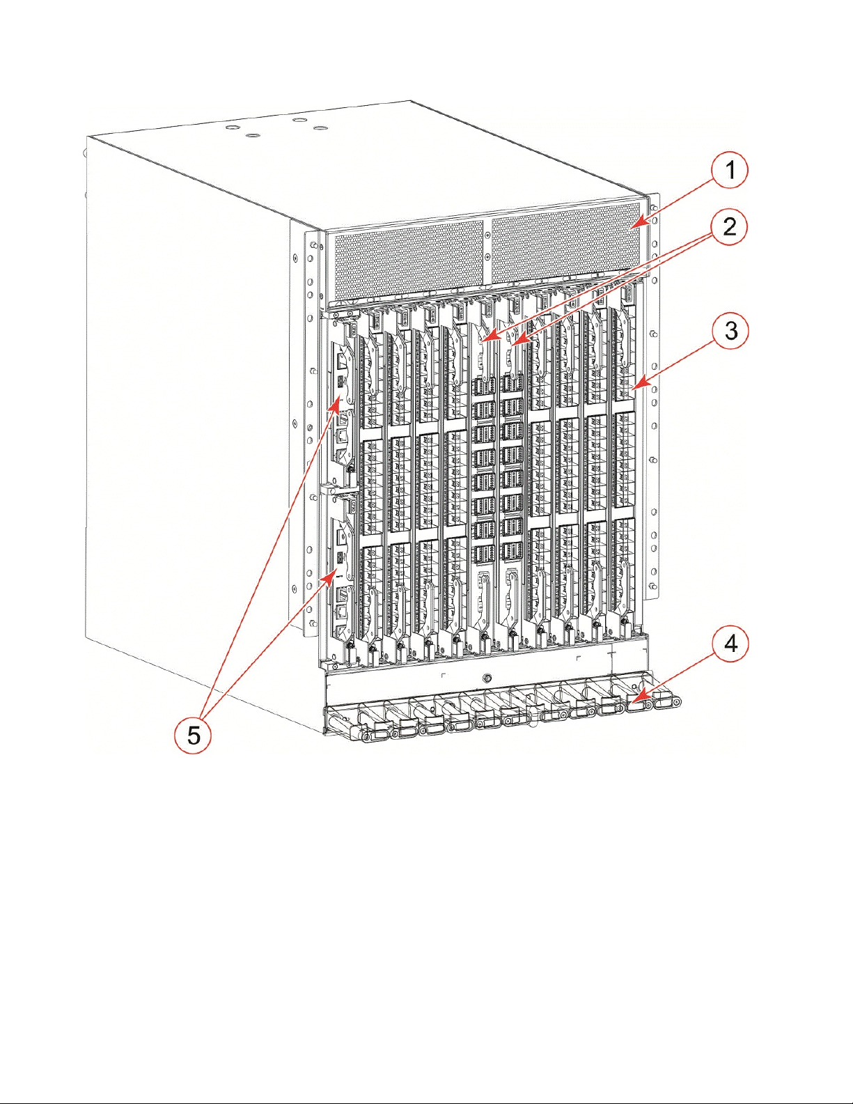
1 - Air vent
2 - Core routing blades (CR32-8)
3 - Port blades (FC32-48)
4 - Cable management comb
5 - Control processor blades (CPX6) – slot 1 (upper), slot 2 (lower)
Figure 1. Port side of the SAN512B-6 (sample configuration)
Notes:
v Depending on the fans and power supplies installed, airflow can be from the
port side to the nonport side of chassis or from the nonport side to the port side
of the chassis.
v Do not attempt to lift the chassis by the protective cover attached over the air
vents at the top of the chassis.
4 SAN512B-6 Installation, Service, and User Guide
Page 29

Port-side slot numbering
The SAN512B-6 contains 10 full-height slots and two half-height slots, for a total of
12 slots. Facing the port side of the device, the half-height slots are on the left,
numbered 1 (top slot) and 2 (bottom slot). The remaining full-height slots are
numbered 3 through 12, counting from left to right of chassis.
Slots contain guide pins and connectors designed for specific blade types. Only
install the control processor (CP), core routing (CR), port, and extension blades into
slot numbers as follows:
v Slots 1– 2 are restricted to CP blades. Note that the blade installed in slot 1 will
be designated as CP0, while the blade in slot 2 will be designated as CP1 in CLI
command and message output.
v Slots 3–6 and slots 9–12 are restricted to port and extension blades.
v Slots 7– 8 are restricted to CR32-8 blades.
Nonport-side view of the device
The following illustration shows the nonport-side view of the SAN512B-6 with all
fan and power supply assemblies installed.
Chapter 1. Introducing the SAN512B-6 5
Page 30
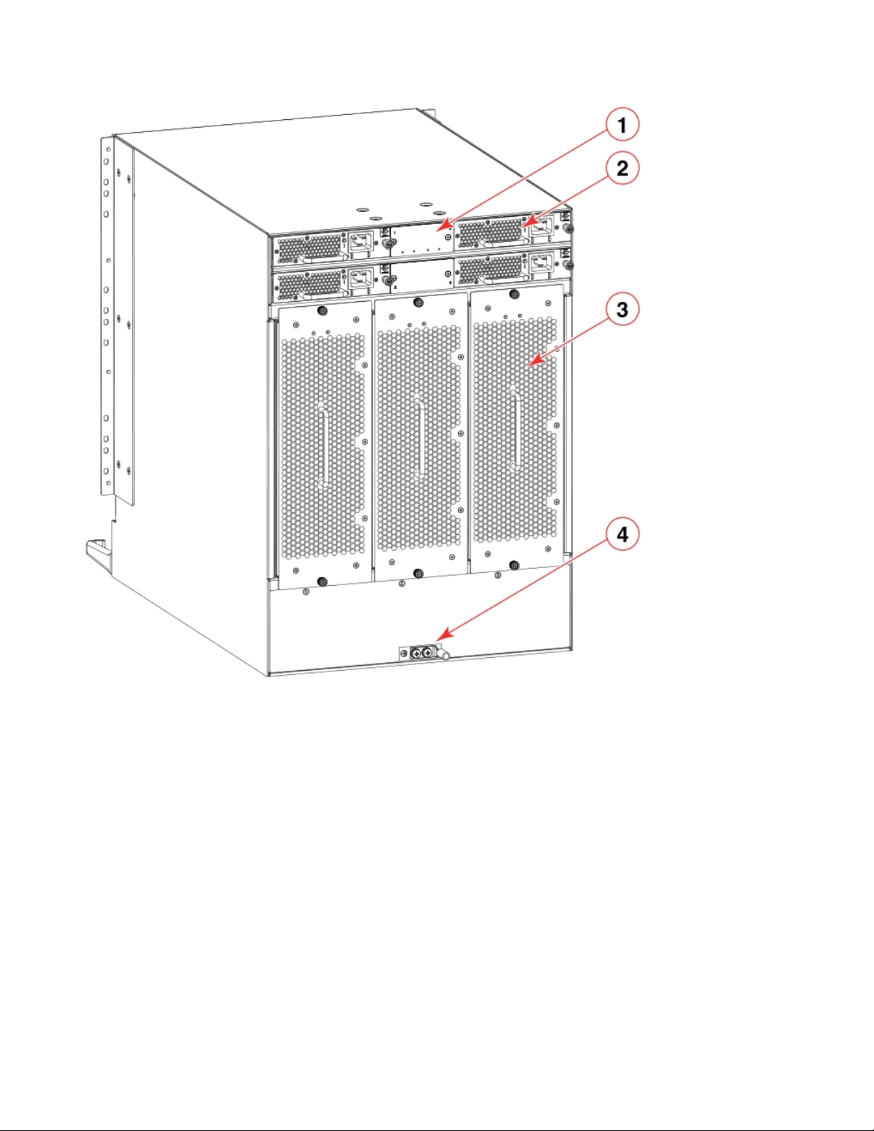
Figure 2. Nonport side of the SAN512B-6 (sample configuration)
1 - WWN bezel (WWN cards behind)
2 - Power supply assembly
3 - Fan assembly
4 - 2AWG Panduit LCD2-14AF lug for building ground connection
Depending on fans and power supplies installed, airflow can be from the port side
to the nonport side of the chassis or the nonport side to the port side of chassis.
Although not illustrated, the chassis label containing the serial number, SKU, and
WWN is located on the lower portion of the chassis, below the fan assemblies.
6 SAN512B-6 Installation, Service, and User Guide
Page 31

Chapter 2. Preparing for the Installation
This chapter provides the following information:
v “Safety precautions”
v “Facility requirements” on page 10
v “Time and items required for installation” on page 11
v “Quick installation checklists” on page 13
v “Items shipped” on page 15
Safety precautions
When using this product, observe all danger, caution, and attention notices in this
manual. The safety notices are accompanied by symbols that represent the severity
of the safety condition.
Refer to the Cautions and Danger Notices at the end of this guide for translations
of safety notices for this product.
General precautions
DANGER
The procedures in this manual are for qualified service personnel.
DANGER
Before beginning the installation, see the precautions in “Power
precautions.”
CAUTION:
Changes or modifications made to this device that are not expressly
approved by the party responsible for compliance could void the
user's authority to operate the equipment.
CAUTION:
Disassembling any part of the power supply and fan assembly voids
the warranty and regulatory certifications. There are no
user-serviceable parts inside the power supply and fan assembly.
CAUTION:
Make sure the airflow around the front, sides, and back of the device
is not restricted.
CAUTION:
To protect the serial port from damage, keep the cover on the port
when not in use.
© Copyright IBM Corp. 2017 7
Page 32

CAUTION:
Never leave tools inside the chassis.
CAUTION:
Use the screws specified in the procedure. Using longer screws can
damage the device.
ESD precautions
DANGER
For safety reasons, the ESD wrist strap should contain a series 1
megaohm resistor.
Power precautions
DANGER
For safety reasons, the ESD wrist strap should contain a series 1
megaohm resistor.
DANGER
If the installation requires a different power cord than the one
supplied with the device, make sure you use a power cord
displaying the mark of the safety agency that defines the
regulations for power cords in your country. The mark is your
assurance that the power cord can be used safely with the device.
DANGER
Make sure that the power source circuits are properly grounded,
then use the power cord supplied with the device to connect it to
the power source.
CAUTION:
Use a separate branch circuit for each power cord, which provides
redundancy in case one of the circuits fails.
DANGER
High Touch Current. Earth connection essential before connecting
supply.
8 SAN512B-6 Installation, Service, and User Guide
Page 33

Lifting precautions
18-32kg(39.7-70.5lbs)
svc00167
18-32kg(39.7-70.5lbs)
svc00167
18-32kg(39.7-70.5lbs)
svc00167
18-32kg(39.7-70.5lbs)
svc00167
CAUTION:
Use safe lifting practices when moving the product.
CAUTION:
A fully populated chassis weighs approximately 145.83 kg (321.5 lbs)
and requires a hydraulic or assisted lift to install it.
Note: Do not attempt to lift the device by the protective cover attached
to the air vents on the nonport-side of the chassis.
DANGER
If a lift tool with a capacity of at least 350 lb is not available, the
director chassis must be depopulated completely before installing
it into the rack. Remove the power supplies, fan modules, all of the
blades, the cable management comb, and the chassis door (if
equipped). Install the empty chassis into the rack following the
chassis installation instructions. The weight of the empty chassis is
78.5 lb (35.6 kg) and must be lifted by minimum 3 people. After
securing the chassis to the rack, reinstall the power supplies, fan
modules, and the blades and proceed with the installation.
Laser precautions
DANGER
All fiber-optic interfaces use Class 1 lasers.
DANGER
Laser Radiation. Do Not View Directly with Optical Instruments.
Class 1M Laser Products.
DANGER
Use only optical transceivers that are qualified by Brocade
Communications Systems, Inc. and comply with the FDA Class 1
radiation performance requirements defined in 21 CFR Subchapter
I, and with IEC 825 and EN60825. Optical products that do not
comply with these standards might emit light that is hazardous to
the eyes.
Chapter 2. Preparing for the Installation 9
Page 34

Facility requirements
Before installing the device, be sure the following facilities requirements are met.
Table 2. Facility requirements
Type Requirements
Device specifications Ensure that the facility can accommodate system, power, and
Electrical Ensure that there are dedicated electrical branch circuits with the
environmental specifications for this device as outlined in the
Appendix B, “Product specifications,” on page 235.
following characteristics are available:
v 200–240 VAC, 50-60 Hz, four branch circuits are recommended
for high availability and maximum blade usage.
v 110–120 VAC, 50–60 Hz, four branch circuits are highly
recommended.
v Four cables for 110–120 VAC or 200–240 VAC service.
v Protected by a circuit breaker in accordance with local electrical
codes.
v Supply circuit, line fusing, and wire size adequate to the
electrical rating on the chassis nameplate.
v Location close to the chassis and easily accessible.
v Grounded outlets installed by a licensed electrician and
compatible with the power cords.
Ensure that all equipment in rack is grounded through a reliable
branch circuit connection.
Make sure that power distribution units (PDUs) can handle
maximum input amperage of power supplies. Use cables with
adequate amperage rating from PDUs to power source.
Thermal Ensure that the air intake and exhaust vents have a minimum of
5.1 cm (2 in.) of airspace.
Ensure that the air intake temperature is less than 40°C (104°F)
during operation.
10 SAN512B-6 Installation, Service, and User Guide
Page 35

Table 2. Facility requirements (continued)
Type Requirements
Rack (when
rack-mounted)
Ensure that these airflow requirements are met:
v Plan to install the device with the air-intake side facing the cool
air aisle. The device can be installed facing either direction if
serviceability and cooling requirements are met.
v Ensure that the airflow available at the air vents meets the
minimum requirements for the device.
v Install the device with the airflow aligned with other devices in
the rack. Some devices have airflow running from port side to
nonport side and others have the opposite arrangement. Make
sure that the airflow for all devices moves in the same direction
to maximize cooling.
Ensure that the following amount of space is available in the rack:
v 14 rack units (14U) high. 1U is equal to 4.45 cm (1.75 inches).
v 61.29 cm (24.09 inch) deep.
v 43.74 cm (17.22 inch) wide.
Ensure that the rack meets these additional requirements:
v Additional weight of chassis will not exceed the rack’s weight
limits.
v The rack is secured to ensure stability in case of unexpected
movement.
Time and items required for installation
You can set up and install the device in the following ways:
v As a standalone unit on a flat surface.
v In a 19-inch Electronic Industries Association (EIA) rack or in a
telecommunications (Telco) rack using a rack mount kit. Refer to“Mounting
options” on page 17 for applicable rack mount kits.
The following table describes the main installation and setup tasks, the estimated
time required for each, and the items required to complete the task for a device
that is fully populated with port blades. Configurations with fewer blades or ports
require less time. These time estimates assume a prepared installation site and
appropriate power and network connectivity.
Chapter 2. Preparing for the Installation 11
Page 36

Table 3. Installation tasks, time, and items required
Installation task Time estimate Items required
Site preparation and
unpacking the device.
Installing rack mount kit . 30 minutes Refer the procedures for
Mounting and securing the
device in rack.
Installing power cables and
powering on the device.
Establishing serial
connection, logging in to the
device, and configuring IP
addresses.
30 minutes 1/2-in. socket wrench
(optional).
#1 and #2 Phillips
screwdrivers.
Pallet jack.
Hydraulic or assisted lift
with a minimum raise of 140
cm (55 in.) and a minimum
capacity of 158.76 kg (350 lb)
To find the weight of your
device fully populated with
the required port blades,
refer to Appendix B,
“Product specifications,” on
page 235.
30 minutes
20 minutes Power cables. These are
20 minutes Serial cable (provided in the
your rack mount kit located
in this guide.
ordered and shipped
separately based on country
where device is installed.
accessory kit).
Workstation computer with a
serial port or terminal server
port and a terminal emulator
application (such as
HyperTerminal).
Installing an Ethernet cable,
opening a Telnet session, and
configuring the device
domain ID, date and time,
and additional system
parameters. Verify and back
up configuration.
Installing transceivers as
needed.
Attaching fiber-optic cables,
cable ties, and cable guides.
12 SAN512B-6 Installation, Service, and User Guide
Ethernet IP addresses for the
device and for both control
processor blades; total of
three addresses.
20 minutes Ethernet cabling (optional)
for Telnet access.
Refer to the Fabric OS
Administrator's Guide.
20-30 minutes or longer if
you are using high-density
port blades.
2-3 hours Fiber-optic cables, cable ties,
SFP+ and QSFP28 optical
transceivers as needed.
and cable management
comb.
Page 37

Quick installation checklists
These checklists provides a high-level overview of the basic installation process
from the planning stage to the point where the device comes online and is ready to
be deployed. Completing all the tasks in the suggested order ensures successful
installation. It is recommended that you print these checklists and take them to the
installation site.
Pre-installation tasks
Review all installation requirements ahead of time as part of your site preparation.
Careful planning and site preparation ensures seamless installation, especially
when installing multiple devices.
Table 4. Installation prerequisites
Task Task details or additional information Completed
Unpack the device. Take an inventory of the hardware components included in your
shipment. Refer to “Items shipped” on page 15.
Gather necessary components and
required tools.
Review the safety precautions. Refer to “Safety precautions” on page 7.
Plan the installation. Obtain the appropriate rack mount kit. Refer to “Mounting options”
Review and verify installation
requirements.
Gather network configuration
parameters.
Review the time and items required information at the beginning of
the following sections in this guide to ensure you have gathered all
necessary components required:
v Mounting the Device
v Initial Setup and Verification
v Port and Extension Blades (if required to install)
v Power Supplies (if required to install)
on page 17.
Verify that the following requirements are met. Refer to “Facility
requirements” on page 10.
v Electrical
v Environmental
v Rack
v Thermal
v IP address
v Subnet mask
v Default gateway
v Domain ID
v Time zone
Installation and initial configuration
The initial setup includes mounting the device on a flat surface or in a rack and
completing the configuration tasks necessary to bring the device online and verify
the operation.
Table 5. Installation and basic system configuration
Task Task details or additional information Completed
Install blades or power supply
assemblies
Install any blades or power supply assemblies that have shipped
separately from the chassis. Be sure to use a #1 Phillips screwdriver
for captive screws to lock these FRUs into place.
Chapter 2. Preparing for the Installation 13
Page 38

Table 5. Installation and basic system configuration (continued)
Task Task details or additional information Completed
Mount the device Choose one of the following mounting options:
v Mount the device in a four-post rack. Refer to the instructions in
this guide for mounting your device in a four-post rack.
v Mount the device in a two-post rack. Refer to the instructions in
this guide for mounting your device in a two-post rack.
Check the airflow of the power
supply and fan assembly
Gather all components required
for the initial setup
Provide power to the device Refer to “Providing power to the device” on page 39.
Attach a management station,
establish a serial connection, and
change the default passwords
(optional)
Set the IP address, subnet mask,
and the default gateway IP
address
Set the date and time
Customize the switch name and
chassis name
Establish an Ethernet connection By establishing an Ethernet connection, you can complete the
Optional: Configure the DNS
service
Optional: Customize the domainIDUse the configure command to change the domain ID (default ID
The airflow direction of the power supply and fan should match.
The power supplies and fan trays are clearly labeled with either a
green arrow with an "E", or an orange arrow with an "I." For more
details, refer to “Fan and power supply airflow” on page 162.
Refer to “Items required” on page 38.
Refer to “Establishing a serial connection to the device” on page 46.
After completing this task, log in to the serial port to configure the
device.
Use the ipaddrset command to configure a static device IP address,
subnet mask, and gateway IP address, or you can use a DHCP
server to obtain the information dynamically. Refer to “Configuring
the IP addresses” on page 48.
v Use the date command to display and set the date and time.
v Use the tstimezone command to display and set the time zone.
v Use the tsclockserver command to synchronize the time with an
external NTP server.
Refer to “Setting the date and time” on page 50 for more
information.
v Use the switchname command to change the default switch name.
v Use the chassisname command to change the default chassis
name.
Refer to“Customizing the chassis and switch name” on page 53 for
more information.
device configuration using a serial session, Telnet, or management
application, such as IBM Network Advisor. Refer to“Establishing an
Ethernet connection to the device” on page 49.
Use the dnsconfig command to create DNS server entries. Refer to
theFabric OS Administrator's Guide.
is 1). Refer to“Setting the domain ID” on page 50 for more
information.
14 SAN512B-6 Installation, Service, and User Guide
Page 39

Table 5. Installation and basic system configuration (continued)
Task Task details or additional information Completed
Verify that the device operates
correctly
Back up the configuration Use the interactive configupload command to back up the
Optional: Power off the devices Enter the shutdown command and wait for the device to power
v Check the LEDs to verify operation of functional parts. Refer to
the Monitoring the Device section of this guide.
v The following commands can be useful to establish an
operational baseline for the device. Refer to the Fabric OS
Command Reference for more information on these commands.
– psshow
– fanshow
– tempshow
– historyshow
– errdump
configuration. Refer to “Backing up the configuration” on page 55
for more information.
down, and then unplug the power cords. Refer to “Powering down
the chassis” on page 56 for more information.
Items shipped
When unpacking the device, follow procedures under "Unpacking and transporting
the device". Verify that you have the following items. Save shipping cartons and
packaging in the event you need to return the device.
Packaged in device shipping carton:
v SAN512B-6 switch with shipping tray
v Packing foam
v Antistatic plastic
v Inner foam
Packaged in device shipping carton or separate carton.
v Door (for EMI compliancy)
v Power cords as ordered for installed power supplies
v Serial cable
v ESD wrist strap
v SFP extraction tool
v Power cord retainer clips
v Cable management comb assembly
v China-RoHS Hazardous/Toxic Substance statement
v Network Advisor web pointer card
v IBM documentation web pointer card
v Rack mount kit for your device
v Ground lug kit
Chapter 2. Preparing for the Installation 15
Page 40

16 SAN512B-6 Installation, Service, and User Guide
Page 41

Chapter 3. Mounting the Device
18-32kg(39.7-70.5lbs)
svc00167
This chapter provides the following information:
v “Mounting options”
v “Mounting precautions”
v “Unpacking and transporting the device” on page 19
v “Port-side slot numbering” on page 5
v “Installing the 14U Rack Mount Kit for Four-Post Racks” on page 20
v “Installing the 14U Chassis Mid-Mount Rack Kit for Two-Post Racks” on page 28
v “Removing the protective cover” on page 34
Mounting options
You can mount the device in the following locations:
v In a four-post 19 in. (48.3 cm) EIA rack:
– Use the 14U rack mount kit for four-post racks (XBR-DCX-0120), which
contains shelf brackets that telescope from 27 in. (68.58 cm) to 31 in. (78.74
cm) to fit the majority of racks.
– Use the 14U rack mount kit for four-post racks (XBR-DCX-0152), which
contains 22 in. (55.88 cm) fixed shelf brackets designed for specific racks.
– Refer to “Installing the 14U Rack Mount Kit for Four-Post Racks” on page 20
for instructions.
v In a two-post Telco rack:
– Use the 14U mid-mount rack kit for two-post racks (XBR-DCX-0121).
– Refer to “Installing the 14U Chassis Mid-Mount Rack Kit for Two-Post Racks”
on page 28 for instructions .
Note: Review the “Mounting precautions” before mounting the device and ensure
that all “Facility requirements” on page 10 are met.
Mounting precautions
The following precautions specifically apply to mounting the device.
CAUTION:
Do not use the port cover tabs to lift the module. They are not
designed to support the weight of the module, which can fall and be
damaged.
DANGER
Make sure the airflow around the front, sides, and back of the
device is not restricted.
© Copyright IBM Corp. 2017 17
Page 42

18-32kg(39.7-70.5lbs)
svc00167
DANGER
18-32kg(39.7-70.5lbs)
svc00167
18-32kg(39.7-70.5lbs)
svc00167
18-32kg(39.7-70.5lbs)
svc00167
Mount the devices you install in a rack as low as possible. Place
the heaviest device at the bottom and progressively place lighter
devices above.
DANGER
Use safe lifting practices when moving the product.
CAUTION:
To prevent damage to the chassis and components, never attempt to
lift the chassis using the fan or power supply handles. These handles
were not designed to support the weight of the chassis.
CAUTION:
Do not attempt to lift the chassis by the protective cover attached over
the air vents on the port side.
CAUTION:
You can connect the device to building ground by connecting an
appropriate 2 AWG wire from a grounded connection to the 2AWG
Panduit LCD2-14AF lug on the nonport-side of the device.
18 SAN512B-6 Installation, Service, and User Guide
Page 43

Unpacking and transporting the device
About this task
Use the following procedure to unpack and install your device.
DANGER
A fully populated chassis weighs approximately 145.83 kg (321.5 lbs) and
requires a hydraulic or assisted lift to install it.
If a lift tool with a capacity of at least 350 lb is not available, the director
chassis must be depopulated completely before installing it into the rack.
Note any possible interconnecting cables so that you will be able to reconnect
them correctly. Remove the power supplies, fan modules, all of the blades,
the cable management comb, and the chassis door (if equipped). Install the
empty chassis into the rack following the chassis installation instructions.
The weight of the empty chassis is 78.5 lb (35.6 kg) and must be lifted by
minimum 3 people. After securing the chassis to the rack, reinstall the power
supplies, fan modules, the blades and any possible interconnecting cables
and proceed with the installation.
Procedure
1. Unpack the device.
a. Cut the bands that encircle the packaging.
b. Open the top of the shipping box and remove accessory kit, rack mount
kits, and foam from the top of the device.
c. Lift the cardboard shipping container and inner cardboard sleeve off the
device.
d. Remove the antistatic plastic off the device.
e. Leave the device on top the foam shipping tray and wood pallet if the
device must be transported to the installation location.
f. Verify the contents of the shipping carton by referring to “Items shipped”
on page 15.
g. Save foam packing material and wooden pallet for reuse.
2. Use a pallet jack or other assisted lift to transport the device to the installation
area. Doorways must be wider than 36 in. (91 cm) to accommodate the device.
3. Remove the chassis door if installed.
4. Remove the cable management comb if attached to the device.
5. Use a lift to raise the device to the correct level. Use two people, one to
operate the lift and the other to secure the device on the lift.
Note: Do not attempt to lift the device by the protective cover attached to
over the air vents on the port side of the chassis.
Note: Orient the device on the lift so that you can slide it into correct side of
rack to provide cool air intake. Fans and power supply FRUs in this device
have a green "E" or "I" symbol on the FRU faceplate. An "E" indicates that the
FRU pulls air from the port side of the device and exhausts out the nonport
side. An "I" indicates that the FRU pulls air from the nonport side of the
device and exhausts out the nonport side. Fans and power supplies must have
Chapter 3. Mounting the Device 19
Page 44

the same airflow indicator. Be sure that you are pulling cool air into the air
intake side of the device. For more details, refer to“Fan and power supply
airflow” on page 162.
6. If applicable, lock the wheels of the lift.
7. Install the applicable rack mount kit in your equipment rack and mount the
device using the rack mount kit's installation instructions.
Note: When installing the device into the rack, use one person on each side of
the device to gently slide it onto the final installation surface and ensure that
it remains supported during the transfer.
8. Reinstall the cable management comb if you removed it.
9. Install the vertical cable management fingers on the rack's upright posts.
10. Reinstall the chassis door. The door must be installed to meet EMI
compliance.
Port-side slot numbering
The SAN512B-6 contains 10 full-height slots and two half-height slots, for a total of
12 slots. Facing the port side of the device, the half-height slots are on the left,
numbered 1 (top slot) and 2 (bottom slot). The remaining full-height slots are
numbered 3 through 12, counting from left to right of chassis.
Slots contain guide pins and connectors designed for specific blade types. Only
install the control processor (CP), core routing (CR), port, and extension blades into
slot numbers as follows:
v Slots 1– 2 are restricted to CP blades. Note that the blade installed in slot 1 will
be designated as CP0, while the blade in slot 2 will be designated as CP1 in CLI
command and message output.
v Slots 3–6 and slots 9–12 are restricted to port and extension blades.
v Slots 7– 8 are restricted to CR32-8 blades.
Installing the 14U Rack Mount Kit for Four-Post Racks
Use the following instructions to install a modular device in a 19-in. (48.3 cm) EIA
rack using the 14U Rack Mount Kit for Four-Post Racks. Any updates to these
instructions will be added to the hardware installation guide for your product.
Two rack-mount kits are available.
1. Contains shelf brackets that telescope from 27 in. (68.58 cm) to 31 in. (78.74 cm)
to fit the majority of racks.
2. Contains 22 in. (55.88 cm) fixed shelf brackets that are designed for specific
racks.
Note: Hardware devices illustrated in these procedures are only for reference and
may not depict the device you are installing into the rack.
Time and items required
Allow approximately one hour to unpack and install a device in a rack.
The following tools are required when installing the 14U Rack Mount Kit for
Four-Post Rack:
v Torque screwdriver with #2 Phillips screwdriver tip
20 SAN512B-6 Installation, Service, and User Guide
Page 45

v Slotted (flat blade) screwdriver
v Hydraulic or assisted lift with a minimum raise of 140 cm (55 in.) and a
Parts list
The following table lists the parts supplied in the 14U Chassis Rack Mount Kit. for
Four-Post Racks.
Note:
Depending on the device and installation, not all parts may be used on the device
type.
minimum capacity of 158.76 kg (350 lbs)
DANGER
If a lift tool with a capacity of at least 350 lbs is not available, the director
chassis must be depopulated completely before installing it into the rack.
Note any possible interconnecting cables so that you will be able to
reconnect them correctly. Remove the power supplies, fan modules, all of
the blades, the cable management comb, and the chassis door (if equipped).
Install the empty chassis into the rack following the chassis installation
instructions. The weight of the empty chassis is 78.5 lbs (35.6 kg) and must
be lifted by minimum 3 people. After securing the chassis to the rack,
reinstall the power supplies, fan modules, the blades and any possible
interconnecting cables and proceed with the installation.
Chapter 3. Mounting the Device 21
Page 46

1 - Left rack mount shelf bracket
2 - Right rack mount shelf bracket
3 - 10-32 x 5/8 in. (1.58 cm) panhead Phillips screw and washer
4 - 10-32 clip nut for racks that have rails with round holes
5 - 1/4-20 x 1/2 in. (1.27 cm) panhead Phillips screw with lock washer for racks that have rails with round holes
6 - 10-32 retainer nut for racks that have rails with square holes
7 - 1/4-20 x 1/2 in. (1.27 cm) panhead Phillips screw with thread locker for racks that have rails with square holes
8 - 3/8 in. (0.953 cm) alignment washer for racks that have rails with square holes
Figure 3. Rack kit parts
|
|
|
|
|
Parts list – NEBS kit
The following table lists the parts supplied in the NEBS KIT to help direct airflow
away from the rack area. This kit is only supported for specific devices, and may
not apply to the device that you are installing.
Note: Depending on the device and installation, not all of the parts may be used.
22 SAN512B-6 Installation, Service, and User Guide
Page 47

|
|
Verify that the items listed in the following figure are included in the NEBS kit.
|
|
Figure 4. NEBS kit parts list
|
|
|
|
|
|
|
|
|
Assembling the rack hardware
1. Left cable comb assembly (1)
2. Right cable comb assembly (1)
3. Air filter (1)
4. Chassis door (1)
5. Velcro strap (8)
6. Screw, 10-32 x .63-in., square cone washer (10)
7. Screw, 8-32 x .312 in., flathead (20)
8. Nut retainer (6)
About this task
Attach the left and right rack mount shelf brackets to the rack rails.
Chapter 3. Mounting the Device 23
Page 48

Note: If cables are to be routed down through the cable management comb, allow
space below the brackets for cable management.
Procedure
1. Locate the shelf brackets in the device.
2. Locate and loosen the screws on the adjustable ends of the brackets (see the
following figure) to allow for adjustment to rack depth.
Figure 5. Left and right shelf brackets installed on rails
1 - Left rack mount shelf bracket
2 - Right rack mount shelf bracket
3 - 1/4-20 x 1/2 in. (1.27 cm) panhead Phillips screw with lock washer for
rails with round holes (4 on each end of each bracket, 16 total)
4 - 3/8 in. (0.953 cm) alignment washer for rails with square holes (4 on
each end of each bracket, 16 total)
5 - 1/4-20 x 1/2 in. (1.27 cm) panhead Phillips screw with thread locker for
rails with square holes (4 on each end of each bracket, 16 total)
6 - Adjustable ends of shelf brackets
7 - Intake air direction
8 - Exhaust air direction
CAUTION:
Use the screws specified in the procedure. Using longer screws can
damage the device.
3. Position the shelf brackets with the adjustable ends on the intake air aisle side
of the rack (see the previous figure).
v For rails with round holes, do the following:
– Position the left and right rack mount shelf brackets and attach them to
the rack rails. Use eight screws with lock washers per bracket (four on
each end). Tighten the screws to a torque of 80 in-lb (92 cm-kg).
v For rails with square holes, do the following:
24 SAN512B-6 Installation, Service, and User Guide
Page 49

– Position the left and right rack mount shelf brackets and attach them to
the rack rails. Use eight screws and alignment washers per bracket (four
on each end). Tighten the screws to a torque of 80 in-lb (92 cm-kg).
Figure 6. Nut and screw locations for mounting the device
1 - 10-32 clip nuts (for round holes)
2 - Rail
3 - 10-32 retainer nut (for square holes)
4 - Rail
5 - Top screws in shelf bracket
6 - Bottom screws in shelf bracket
7 - Left rack mount shelf bracket
8 - Right rack mount shelf bracket
9 - Hole 1
Note: Standard EIA rails have holes in sets of three; spaces between the holes
are 5/8 in, 5/8 in, and 1/2 in. (1.58 cm, 1.58 cm, and 1.27 cm).
4. Tighten the adjusting screws on the sliding portion of the rack mount shelf
brackets to a torque of 32 in-lb (37 cm-kg).
5. Attach the clip nuts (for rails with round holes) or retainer nuts (for rails with
square holes) to the vertical rails on the exhaust aisle side of the rack (see the
previous figure). These clip nuts are used for securing the port side of the
Chapter 3. Mounting the Device 25
Page 50

device to the rack rails with 10-32 x 5/8 inch screws. Use three clips on each
18-32kg(39.7-70.5lbs)
svc00167
rail. Place the clips in optimum locations for securing the device to the rails.
Note: Do not align the clip or retainer nuts with the top or bottom holes of the
mounting bracket because the screw heads will interfere with the door.
Installing the device in the rack
About this task
Use the following procedure to install the device in the rack.
DANGER
Use safe lifting practices when moving the product.
Procedure
1. Ensure that the door, if installed, is removed from the port side of the device.
For instructions, refer to instructions for removing and replacing the device
door in the device installation guide.
2. Use a lift to raise the device to the level of the shelf brackets.
3. Move the lift as close as possible to the rack, with the air-intake side of the
device facing the front of the rack (see the following figure).
4. If applicable, lock the wheels of the lift.
5. Gently slide the device onto the shelf brackets, ensuring that it remains
supported during the transfer.
6. Fasten the port side of the device to the rack rails. Use three 10-32 x 5/8 inch
(1.58 cm) screws per rail. Tighten the screws to a torque of 32 in-lb (37 cm-kg).
Refer to Figure 5.
Note: Do not use the top or bottom holes of the mounting bracket because the
screw heads will interfere with the door.
26 SAN512B-6 Installation, Service, and User Guide
Page 51

Figure 7. Positioning the device for installation in a rack
1 - Rack
2 - Nonport side of device
Chapter 3. Mounting the Device 27
Page 52

Figure 8. Attaching port side of device to rack rails
1 - 10-32 x 5/8 in. (1.58 cm) panhead Phillips screw with washer
7. Reinstall the device door if removed from your device. For instructions, refer to
the door removal and replacement procedures in your device installation guide.
Installing the 14U Chassis Mid-Mount Rack Kit for Two-Post Racks
Use the following instructions to install a modular device in a telecommunications
(Telco) rack, using the 14U Chassis Mid-Mount Rack Kit for Two-Post Racks.
The kit is compatible with rack rails that are either 3 inches or 5 inches wide
(adapters are provided for 3-in. rails). Any updates to these instructions will be
added to the hardware installation guide for your product.
Note: Hardware devices illustrated in these procedures are only for reference and
may not depict the device you are installing into the rack.
Time and Items required
Allow approximately one hour to unpack and install a chassis in a rack.
The following tools are required when installing the 14U Chassis Mid-Mount Rack
Kit for Two-Post Racks.
v Torque wrench with #2 Phillips screwdriver tip.
28 SAN512B-6 Installation, Service, and User Guide
Page 53

v Flathead screwdriver.
v Hydraulic or assisted lift with a minimum raise of 140 cm (55 in.) and a
Parts list
The following parts are provided with the 14U Chassis Mid-Mount Rack Kit for
Two-Post Racks.
minimum capacity of 158.76 kg (350 lbs)
DANGER
If a lift tool with a capacity of at least 350 lbs is not available, the director
chassis must be depopulated completely before installing it into the rack.
Remove the power supplies, fan modules, all of the blades, the cable
management comb, and the chassis door (if equipped). Install the empty
chassis into the rack following the chassis installation instructions. The
weight of the empty chassis is 78.5 lbs (35.6 kg) and must be lifted by
minimum 3 people. After securing the chassis to the rack, reinstall the
power supplies, fan modules, and the blades and proceed with the
installation.
Chapter 3. Mounting the Device 29
Page 54

Figure 9. Rack kit parts
1 - Tray, front, mid-mount, chassis
2 - Tray, rear, mid-mount, chassis
3 - Adapter, rear, mid-mount, right
4 - Adapter, rear, mid-mount, left
5 - Screw, 10-32 x 3/8”, pan head Phillips, ST, zinc (requires a torque of 32
inch-pounds)
Note: Not all parts may be used with certain installations depending on the device
type.
Assembling the rack hardware
About this task
Perform the following steps to assemble the rack hardware.
30 SAN512B-6 Installation, Service, and User Guide
Page 55

Procedure
1. Attach the rear tray (with or without adapter, as required) to both rack rails.
Orient the tray (refer the following figure) and use nine screws (Item E) for
each rail.
2. Attach the front tray to both rack rails. Orient the tray (Figure 3) and use nine
screws (Item E) for each rail.
3. Verify that the rear edge of the front tray is seated into the front edge of the
rear tray.
1 - Tray, rear, mid-mount, chassis
2 - Adapter, rear, mid-mount, right
3 - Adapter, rear, mid-mount, left
4 - Screws
Figure 10. Attaching the rear tray to the rack rails
Chapter 3. Mounting the Device 31
Page 56

18-32kg(39.7-70.5lbs)
svc00167
1 - Tray, front, mid-mount, chassis
2 - Screws
Figure 11. Attaching the front tray to the rack rails
Installing the device in the rack
About this task
DANGER
Use safe lifting practices when moving the product.
Note: A fully populated device requires a hydraulic or assisted lift to install into a
rack.
Perform the following steps to load the device into the mid-mount trays.
32 SAN512B-6 Installation, Service, and User Guide
Page 57

Procedure
1. Ensure that the door is removed from the port side of the device. For
instructions, refer to the door removal and replacement procedures in your
device installation guide.
2. Orient the device (refer the following figure) and use a hydraulic lift to raise it
to the level of the trays.
3. If applicable, lock the wheels of the lift.
4. Slide the device into the trays until the front edge of the device is seated
against the front tray.
Figure 12. Placing the device in the trays
1 - Tray, front, mid-mount, chassis
2 - Tray, rear, mid-mount, chassis
5. Use three screws (Item 5) to attach each side of the rear tray to the device (refer
the following figure).
Note: The screw holes in the device walls have pem nuts on the inside surface.
Chapter 3. Mounting the Device 33
Page 58

6. Use four screws (Item 5) to attach each side of the front tray to the device
7. Use six screws (Item 5) to attach the lip on each side of the front tray to the lip
on the front of the device.
Note: Do not use the top or bottom holes of the mounting bracket because the
door will interfere with the screw heads.
Figure 13. Attaching trays to the device
8. Reinstall the device door. For instructions, refer to the door removal and
installation instructions in your device installation guide.
Removing the protective cover
About this task
The chassis ships with a protective cover installed over the air vents at the top of
the port side of the chassis.
34 SAN512B-6 Installation, Service, and User Guide
Page 59

CAUTION:
You must remove the protective cover on the port side of the chassis
before applying power to the chassis. The chassis can overheat if air
vents are blocked with this cover.
Remove this cover by removing the Phillips screws securing it to the mounting
bracket on each side of the chassis.
Figure 14. Removing protective cover from SAN512B-6
Note: Do not attempt to lift or support the chassis by the protective cover.
Chapter 3. Mounting the Device 35
Page 60

36 SAN512B-6 Installation, Service, and User Guide
Page 61

Chapter 4. Initial Setup and Verification
This chapter provides the following information:
v “Configuration and verification task guide”
v “Items required” on page 38
v “Providing power to the device” on page 39
v “Establishing a serial connection to the device” on page 46
v “Configuring the IP addresses” on page 48
v “Establishing an Ethernet connection to the device” on page 49
v “Setting the date and time” on page 50
v “Customizing the chassis and switch name” on page 53
v “Veifying the PID mode” on page 53
v “Verifying installed licenses and license key” on page 54
v “Verifying correct operation” on page 54
v “Backing up the configuration” on page 55
v “Powering down the chassis” on page 56
Configuration and verification task guide
Before connecting the device to the fabric, use the following tasks to initially
configure and setup the device, verify correct operation, and back up the
configuration.
The configuration information is mirrored to the standby CP blade, which allows
the current configuration to remain available even if the active CP blade fails. The
configuration information for the device is stored in the WWN cards and the flash
memory of the CP blades. The configuration can be backed up to a workstation
(uploaded) and then downloaded to the active CP blade if necessary.
Note: The device WWN is set by the factory to match the license ID (which is
based on the chassis serial number).
Table 6. Configuration and verification tasks
Task Task details or additional information
Establish a serial connection to the device
(chassis).
Configure IP addresses for the device. Configure an IP address and subnet mask
Connect a serial cable to the console port on
active CP blade and use a terminal emulator
program (such as HyperTerminal on a PC,
or TERM, TIP, or Kermit in a UNIX
environment) to log in to the console port
and device. The blue "Active" LED
illuminates on the active CP blade.
for a chassis management connection.
Configure IP addresses, host names, subnet
masks, and gateway addresses for both
control processor (CP) blades.
© Copyright IBM Corp. 2017 37
Page 62

Table 6. Configuration and verification tasks (continued)
Task Task details or additional information
Establishing an Ethernet connection to the
device.
Set a unique domain ID for the device. Disable the device using the switchDisable
Set the date and time for the device. Use the date, tsTimeZone, and
Customize a switch and chassis name for the
device.
Verify installed licenses and license key Enter the licenseShow command to
Connect Ethernet cable to active CP blade
Ethernet port labeled "Management" and
establish a connection.
command, and then use the configure
command to step through prompts to
configure a domain ID. Use switchEnable to
re-enable the device.
tsClockServer commands to set date, time
zone, and synchronize local time of device
with NTP server.
Use the switchName command, followed by
new name in quote marks (switchname
"bigswitch".)
Use the chassisName command followed by
the new name in quote marks (chassisname
"chassis_002").
determine display enabled licenses and the
license key.
Items required
Enter the licenseIdShow command to obtain
the chassis ID.
Record the license key and chassis ID for
future reference.
Verify correct operation of device. Check LEDs on blades and FRUs, and use
the following commands to verify operation:
v psShow
v fanShow
v switchShow
v fabricShow
v slotShow
v tempShow
v historyShow
v errdump
Back up the configuration. Use the configUpload command.
The following items are required for initial setup and verification of the device:
v The device, mounted and installed with the required blades, FRUs, transceivers,
and cables and is connected to a power source.
v A workstation computer with an installed terminal emulator application, such as
HyperTerminal for Windows.
v An unused IP address with corresponding subnet mask and gateway address.
v A serial cable (provided) with an RJ-45 connector.
v An RJ-45 to DB-9 adapter.
38 SAN512B-6 Installation, Service, and User Guide
Page 63

v Three Ethernet cables (including one spare).
v Access to an FTP server or USB device for backing up (uploading) or
downloading the device configuration or collecting supportsave output data
(optional).
v A USB drive for collecting supportsave output data (optional)
Providing power to the device
Before you begin
Before connecting power, refer the following.
v Electrical caution and danger statements in “Safety precautions” on page 7 and
“Facility requirements” on page 10
v Power supply specifications section in the Appendix B, “Product specifications,”
on page 235 for power supply requirements of your device.
About this task
Perform the steps to provide power that are applicable to your power supply
model. Observe the following for all power connections:
Procedure
1. Connect each power supply to a different power source or circuit to provide
full redundancy.
2. Route the power cords so they will be out of the way when connected to the
power source. Ensure that the power cords have a minimum service loop of
15.2 cm (6 in.) and are routed to avoid stress.
3. Remember that power is supplied to the device as soon as the first power
supply is connected to a power source.
|
|
|
|
|
|
|
|
|
|
|
|||
|
|
|
|
|
|
|
|
Connecting power cord to AC power supplies
About this task
Complete the following steps to connect the power cord from the facility AC
power source to the device 's AC power supply. Before connecting to power, be
sure to observe all "Power Precautions" in “Safety precautions” on page 7. In
addition, refer to the power supply specifications and requirements in Appendix B,
“Product specifications,” on page 235.
Procedure
1. Remove the protective cover if it is still installed over the top air vents on the
port side of the chassis.
CAUTION:
Remove the protective cover on the port side of chassis before
applying power. This cover is attached over the air vents. If not
removed, the chassis can overheat and will eventually shut down.
2. Install all power supplies provided for your device if not already installed.
Refer to “Installing a power supply” on page 169 for procedures.
3. When installing device in a rack, route power cables from power distribution
units (PDUs) so they do not cover air vents in chassis.
Chapter 4. Initial Setup and Verification 39
Page 64

|
|
|
4. Connect the provided AC power cords to a power source with voltage of
200–240 VAC, 50/60 Hz or optionally to a power source with voltage of
100–120 VAC, 50/60 Hz.
|
|||
|
|
|
|
|
|
|
|
|
|
|
|
|
|
|
|
|
|
|
|
|
|
|
|
|
|
|
Note: Use of the high-voltage line (200–240 VAC) is highly recommended
because of better power-conversion efficiency. With 120 VAC primary input, the
power distribution unit (PDU) supplies roughly half the available wattage,
which can limit blade and port configurations. For a "fully-loaded" chassis with
maximum supported blades and optics, two power supplies connected to
200–240 VAC are required for full N+N redundancy. For details on power
supplies required for operation and high availability, refer to "Power supply
requirements" and "Power consumption" tables in the Appendix B, “Product
specifications,” on page 235.
5. Route the cords so they will be out of the way when connected to the power
source. Ensure that the power cords have a minimum service loop of 15.2 cm (6
in.) available and are routed to avoid stress.
6. Plug the power cords into power supplies. The power supply LED will light
green when power is applied. Note that after one power supply is plugged into
AC power, LEDs on the remaining installed power supplies will flash green
until they also have power applied.
The director performs a power-on self-test (POST) each time it is powered on.
POST takes approximately 10 minutes, during which time status LEDs on
installed blades and other FRUs may display amber. Power LEDs on all FRUs
display green when power-on self-test (POST) is complete and all FRUs are
functional. You can bypass POST by using the fastBoot command. You can also
disable POST for successive reboots using the diagDisablePost command.
DANGER
High Touch Current. Earth connection essential before connecting
supply.
|
|
|
|
|
|
|
|
|
|
|
|
|
|
|
|
|
Connecting power cord to HVAC/HVDC power supplies
Note: Do not connect the device to the network until the IP addresses are
configured.
7. After POST is complete, verify that the power LEDs on blades and other FRUs
are green.
For information about LED patterns, refer to Chapter 6, “Monitoring the
switch,” on page 69.
8. Ground the chassis by attaching a ground wire from building ground to an
appropriate crimp connector and attaching the connector to the 2AWG Panduit
LCD2-14AF lug located to the left of the bottom fan assembly near the bottom
of the chassis.
About this task
Use steps in this section to apply power to the dual-function high-voltage AC and
DC (HVAC/HVDC) power supply. This power supply converts high-voltage DC or
AC input to appropriate DC power for the device.
Make sure that you observe the electrical caution and danger statements in “Safety
precautions” on page 7 when connecting this power supply.
40 SAN512B-6 Installation, Service, and User Guide
Page 65

|
|
Note: The equipment installation must meet NEC/CEC code requirements.
Consult local authorities for regulations.
|
|
|
|
|
|
|
|
|
|
|
|
|
|
|
|
|
|
|
|
|
|
|
|
|
|
|
|
|
|
|
|
|
|
|
|
Note: Power is supplied to the device as soon as the first power supply is
connected to a power source.
CAUTION:
The maximum input voltage for connection to the HVAC/HVDC power supply
should not exceed 305 VAC and 400 VDC.
CAUTION:
The maximum input voltage for connection to the HVAC power supply must not
exceed 305VAC.
Procedure
1. If connecting to AC power, attach an AC power plug to the unterminated
wires on the HVAC/HVDC power cord that meets your facility and local code
requirements. If connecting to DC power, verify how you will attach these
unterminated wires to your site's DC power terminal blocks. For more
information on the HVAC/HVDC power cord available for these power
supplies, refer to “Using HVAC/HVDC power cords” on page 45.
2. Ground the chassis by attaching a ground wire from building ground to an
appropriate crimp connector and attaching the connector to the 2AWG
Panduit LCD2-14AF lug located to the left of the bottom fan assembly near
the bottom of the chassis.
3. Remove the protective cover if it is still installed over the top air vents on the
port side of the chassis.
CAUTION:
Remove the protective cover on the port side of chassis before applying
power. This cover is attached over the air vents. If not removed, the chassis
can overheat and will eventually shut down.
4. Install all power supplies provided for your device if not already installed.
Refer to “Installing a power supply” on page 169 for procedures.
5. When installing the device in a rack, route power cables from power
distribution units (PDUs) so they do not cover air vents in chassis.
6. Before connecting the power cord to a power supply, first remove the cable
restraint cover, if it is installed under the power cord connector. Remove the
cover by unscrewing the two torx head screws. Save the retainer cover and
screws for reinstallation after plugging in the power cord.
CAUTION:
When removing the metal cable restraint cover under the high voltage
power supply inlet, remove the 2 Torx head screws only.
|
Chapter 4. Initial Setup and Verification 41
Page 66

|
|
|
|
|
|
|
|
|
|
7. Connect power cords to installed power supplies. The connector on the power
1. Torx head screws
2. Metal cable restraint cover
cord is keyed so that it only fits one way into the power supply connector.
Note that the connector's latch should be positioned under the connector and
will latch when the power cord connector is fully inserted into the power
supply.
42 SAN512B-6 Installation, Service, and User Guide
Page 67

|
|
|
|
|
8. Attach the cable restraint cover under the power cord connector using its two
|
|
|
|
9. If connecting to an AC power source, use the following steps. (If connecting to
|
|
|
|
|
|
|
|
1. Power cable
2. Connector latch
torx head screws (refer to step 4).
Note: This retainer cover protects the power cord from being accidentally
unlatched and disconnected from the power supply.
a DC power source, go on to step 8.)
a. Make sure that you observe the electrical caution and danger statements in
“Safety precautions” on page 7 when connecting this power supply.
b. Make sure that AC power plug is attached to the power-source end of the
HVAC/HVDC power cord that meets your facility and local code
requirements. For more information on the HVAC/HVDC power cord
available for these power supplies, refer to “Using HVAC/HVDC power
cords” on page 45.
Chapter 4. Initial Setup and Verification 43
Page 68

|
|
|
|
|
|
|
DANGER
Make sure that the power source circuits are properly grounded, then
use the power cord supplied with the device to connect it to the
power source.
c. If connecting to an AC power source, connect to a power source with
voltage of 200–277 VAC, 50/60 Hz (recommended).
|
|
|
|
|
|
|
|
|
|
|
|
|
|
|
|
|
|
|
|
|
|
|
|
10. If connecting to an DC power source, use the following steps. (If connecting to
Note: Use of a high-voltage line (200–277 VAC) is highly recommended
because of better power-conversion efficiency. For a "fully-loaded" chassis
with maximum supported blades and optics, two power supplies
connected to 200–277 VAC are required for full N+N redundancy. For
details on power supplies required for operation and high availability, refer
to "Power supply requirements" and "Power consumption" tables in the
Appendix B, “Product specifications,” on page 235.
DANGER
High Touch Current. Earth connection essential before connecting
supply.
CAUTION:
Use a separate branch circuit for each power cord, which provides
redundancy in case one of the circuits fails.
a AC power source, go to step 7.)
a. Make sure that you observe applicable electrical caution and danger
statements in “Safety precautions” on page 7 when connecting this power
supply.
b. Terminate the negative (-) and positive (+) unterminated wires on the
HVAC/HVDC power cord to the DC power source. Connect the ground
wire to building ground. For more information on the HVAC/HVDC
power cord available for these power supplies, refer to “Using
HVAC/HVDC power cords” on page 45.
|
|
|
|
|
|
|
|
|
|
|
|
|
|
|
|
|
|
11. Route the cords so they will be out of the way when connected to the power
12. After power is applied, the power supply LED will light green.
13. After POST is complete, verify that the power LEDs on blades and other FRUs
Note: Make sure that there is an adequate circuit breaker in the DC input
circuit to the system based on input wiring to the product and input
voltage.
source. Ensure that the power cords have a minimum service loop of 15.2 cm
(6 in.) available and are routed to avoid stress.
The director performs a power-on self-test (POST) each time it is powered on.
POST takes approximately 10 minutes, during which time status LEDs on
installed blades and other FRUs may display amber. Power LEDs on all FRUs
display green when power-on self-test (POST) is complete and all FRUs are
functional. You can bypass POST by using the fastBoot command. You can
also disable POST for successive reboots on the device using the
diagDisablePost command.
Note: Do not connect the device to the network until the IP addresses are
configured.
are green.
44 SAN512B-6 Installation, Service, and User Guide
Page 69

|
|
|
|
|
|
For information about LED patterns, refer to Chapter 6, “Monitoring the
switch,” on page 69.
14. Ground the chassis by attaching a ground wire from facilities ground to an
appropriate crimp connector and attaching the connector to the 2AWG
Panduit LCD2-14AF lug located to the left of the bottom fan assembly near
the bottom of the chassis.
|
|
|
|
|
|
|
|
|
|
|||
|||
|||
|||
Using HVAC/HVDC power cords
HVAC/HVDC power supply power cords, available from Brocade, are shipped
with an Anderson Saf-D-Grid®400 connector on the power supply end and three
unterminated 14 AWG UL 600V 90C wires with ring lugs on the power source end.
Power cord length is 6 m (19 ft. 8 in.). For connecting to a power source, attach
either an AC power plug to these wires that meets your facility and local code
requirements, or connect these wires to appropriate DC power terminal blocks.
The following table defines the function of the 14 AWG wires in the power cable:
Table 7. HVAC/HVDC power cable
Wire label Color Function
L+ Brown Return positive (+)
– Blue Negative (-)
PE Green with yellow stripe Earth ground (PE)
|
|
|
|
|
The Anderson Saf-D-Grid®connector on the power supply end of the cord is
keyed so that it only fits one way into the power supply. Note that the connector's
latch should be positioned under the connector and will latch when the power
cord connector is fully inserted into the power supply.
|
Chapter 4. Initial Setup and Verification 45
Page 70

|
|
|
|
1. Power cable
2. Connector latch
Establishing a serial connection to the device
About this task
To establish a serial connection to the console port on the device, complete the
following steps.
Procedure
1. Verify that the device is powered on and that POST is complete by verifying
that all power LED indicators on the power supplies, fans, and blades display a
steady green light.
2. Remove the shipping cap from the console (I0I0) port on the active CP blade.
The active CP is indicated by an illuminated blue LED on the CP blade front
panel.
Note: The console, or serial port is intended primarily for the initial setting of
the IP address and for service purposes.
46 SAN512B-6 Installation, Service, and User Guide
Page 71

3. Use the serial cable provided with the device to connect the console (serial)
port on the active CP to a computer workstation.
Note: The active CP is indicated by an illuminated blue LED, labeled "Active,"
on the CP blade front panel.
If the serial port on the workstation is RJ-45 instead of RS-232, remove the
adapter on the end of the serial cable and insert the exposed RJ-45 connector
into the RJ-45 serial port on the workstation.
4. Access the device using a terminal emulator application (such as
HyperTerminal in a Windows environment or tip in a UNIX environment).
5. Disable any serial communication programs running on the workstation (such
as synchronization programs).
6. Open a terminal emulator application (such as HyperTerminal on a PC, or
TERM, TIP, or Kermit in a UNIX environment), and configure the application
as follows:
v In a Windows environment:
Parameter Value
Bits per second 9600
Data bits 8
Parity None
Stop bits 1
Flow control None
Note: Flow control is not supported on the serial consoles when attached to
remote terminal servers and must be disabled on the customer-side remote
terminal server and the host-side clients.
v In a UNIX environment, enter the following string at the prompt:
tip /dev/ttyb -9600
If ttyb is already in use, use ttya -9600 instead.
When the terminal emulator application stops reporting information, press
Enter. The following login prompt displays:
CP0 Console Login:
Note: CP0 in the preceding prompt is an example. "CP1" will display if it is
the active CP.
7. Log in to the console using admin as the default login name and password as the
default password. As login to the device occurs, you are prompted to change
the device passwords.
Please change passwords for switch default accounts now.
Use Control-C to exit or press ’Enter’ key to proceed.
8. Press Enter to step through a procedure to change the passwords as shown in
the following example. To skip modifying the password, press Ctrl+C.
----------------------------------------------------for user - admin
Changing password for admin
Enter old password:
Enter new password:
Re-type new password:
passwd: all authentication tokens updated successfully
Chapter 4. Initial Setup and Verification 47
Page 72

Passwords can be 8 to 40 characters long. They must begin with an alphabetic
character. They can include numeric characters, periods (.), and underscores (_)
only. Passwords are case-sensitive, and they are not displayed when you enter
them on the command line. For more information on passwords, refer to the
Fabric OS Administrator's Guide.
Configuring the IP addresses
About this task
The device requires three IP addresses, which are configured using the ipAddrSet
command. IP addresses are required for both CP blades (CP0 and CP1) and for
chassis management (shown as SWITCH under the ipAddrShow command) in the
device.
The default IP addresses and host names for the device are:
v 10.77.77.75 / CP0 (the CP blade in slot 1 at the time of configuration)
v 10.77.77.74 / CP1 (the CP blade in slot 2 at the time of configuration)
Use one of the following formats for IPv4 or IPv6 addressing when entering the IP
address using the ipaddrset command:
v If you using an IPv4 IP address, enter the IP address in dotted decimal notation
as prompted.
Ethernet IP Address: [192.168.74.102]
v If using an IPv6 address, enter the network information in colon-separated
notation as prompted.
device:admin> ipaddrset -ipv6 --add 1080::8:800:200C:417A/64
Note:
Resetting an IP address while the device has active IP traffic or has management
and monitoring tools running, such as DCFM, Fabric Watch, and SNMP, can cause
traffic to be interrupted or stopped.
Complete the following steps to set the IP addresses for the device.
Procedure
1. Log into the device through a serial console connection to the active CP blade.
The active CP is indicated by an illuminated blue LED on the blade front panel.
If you are already logged through a console port, you can determine whether
you are logged into the active or standby CP by entering hashow at the prompt.
The following example shows local login at CP1, which is the active blade.
swDir:admin> hashow
Local CP (Slot 2, CP1) : Active, Warm Recovered
Remote CP (Slot 1, CP0) : Standby, Healthy
HA Enabled, Heartbeat Up, HA State Synchronized
2. Configure the chassis management IP address by entering the ipaddrset
-chassis command:
swDir:admin> ipAddrSet -chassis
Enter required information at the prompts. Specify the -chassis IP address. The
-sw 0 IP address is not valid on this device.
Note: The addresses 10.0.0.0 through 10.0.0.255 are reserved and used
internally by the device. External IPs must not use these addresses.
48 SAN512B-6 Installation, Service, and User Guide
Page 73

Following is example configuration for setting the chassis IP address.
swDir:admin> ipaddrset -chassis
DHCP [Off]:
Ethernet IP Address [10.0.0.0]:192.168.1.1
Ethernet Subnetmask [255.0.0.0]:255.255.240.0
IP address is being changed...
3. Set up the CP0 IP address by entering the ipaddrset -cp 0 command:
swDir:admin> ipAddrSet -cp 0
Enter required information at the prompts. Following is example configuration
for setting the CP0 IP address
swDir:admin> ipaddrset -cp 0
DHCP [Off]:
Host Name [cp0]:
Ethernet IP Address [10.0.0.0]:192.168.1.2
Ethernet Subnetmask [255.0.0.0]:255.255.260.0
Gateway IP Address [10.0.0.0]:10.38.160.1
IP address is being changed...
Done.
4. Set up the CP1 IP address by entering the ipaddrset -cp 1 command:
swDir:admin> ipAddrSet -cp 1
Enter required information at the prompts. Following is example configuration
for setting the CP1 IP address.
Following is sample configuration for setting the CP1 IP address:
swDir:admin> ipaddrset -cp 1
DHCP [Off]:
Host Name [cp0]:
Ethernet IP Address [10.0.0.0]:192.168.3
Ethernet Subnetmask [255.0.0.0]:255.255.230.0
Gateway IP Address [10.0.0.0]:10.38.160.1
IP address is being changed...
Done.
Establishing an Ethernet connection to the device
About this task
After using a serial connection to configure the IP addresses for the device, you
can connect the active CP blade to the local area network (LAN).
Note: Connecting the CP blades to a private network or VLAN is recommended.
After establishing an Ethernet connection, you can complete the device
configuration using a serial console connection, Telnet connection, or management
applications, such as Web Tools or IBM Network Advisor.
Perform the following steps to establish an Ethernet connection to the device.
Procedure
1. Remove the shipping plug from the Ethernet port on the active CP blade. The
active CP is indicated by an illuminated blue LED on the blade front panel.
2. Insert one end of an Ethernet cable into the Management (MGMT) Ethernet
port.
3. Connect the other end to an Ethernet 10/100/1000 BaseT LAN.
4. Complete any additional device configuration procedures for the device using
one of the following steps:
v Log into the device using a serial console connection and admin login.
Chapter 4. Initial Setup and Verification 49
Page 74

v Log into the device through a Telnet session using the chassis management
IP address and admin login.
Setting the domain ID
About this task
Each device in the fabric must have a unique domain ID. The default domain ID is
1. If the device is not powered on until after it is connected to the fabric and the
default domain ID is already in use, the domain ID for the new device is
automatically reset to a unique value. If the device is connected to the fabric after
it has been powered on and the default domain ID is already in use, the fabric
segments.
You can use the fabricShow command on another device in the fabric to view
domain IDs already assigned. Manually configure a unique domain ID using the
configure command as in the following steps:
Procedure
1. Log into the device using one of the following methods:
v A serial console connection to the active CP blade. The active CP is indicated
by an illuminated blue LED on the blade front panel.
v A Telnet session using the chassis management IP address.
2. Log into the device using admin as your password. If you have not changed the
default password, usepassword.
3. Perform the following steps to modify the Domain ID.
a. Disable the device by entering the switchDisable command.
b. Enter the configure command. The command prompts display sequentially.
Enter a new value or press Enter to accept each default value.
c. Enter y after the "Fabric param" prompt.
Fabric param (yes, y, no, n): [no] y
d. Enter a unique domain ID (such as the domain ID used by the previous
device, if still available).
Domain: (1..239) [1] 3
e. Complete the remaining prompts or press Ctrl+D to accept the remaining
settings without completing all the prompts.
f. Re-enable the device by entering the switchEnable command.
Setting the date and time
About this task
The date and time settings are used for logging events, error detection, and
troubleshooting, and hence you should set them correctly. However, device
operation does not depend on the date and time; a device with incorrect date or
time values still functions properly.
You can synchronize the local time of the principal or primary fabric configuration
server (FCS) device to that of an external Network Time Protocol (NTP) server.
Perform the following steps to set the date and time.
50 SAN512B-6 Installation, Service, and User Guide
Page 75

Procedure
1. Log into the device using one of the following methods:
v A serial console connection to the active CP blade. The active CP is indicated
by an illuminated blue LED on the blade front panel.
v A Telnet session using the chassis management IP address.
2. Log into the device using admin. If you have not changed the default password,
usepassword.
3. Enter the date command, using the following syntax:
date "mmddHHMMyy"
The values are:
v mm is the month; valid values are 01 through 12.
v dd is the date; valid values are 01 through 31.
v HH is the hour; valid values are 00 through 23.
v MM is minutes; valid values are 00 through 59.
v yy is the year; valid values are 00 through 99 (values greater than 69 are
interpreted as 1970 through 1999, and values less than 70 are interpreted as
2000 through 2069).
switch:admin> date
Fri Sep 28 17:01:48 UTC 2016
switch:admin> date "0927123016"
Thu Sep 27 12:30:00 UTC 2016
switch:admin>
Setting the time zone
About this task
The default time zone is Coordinated Universal Time (UTC). The time zone needs
to be set only once because the value is stored in nonvolatile memory. Use the
following procedure to set the time zone. The time zone change will take affect
after the next system reboot.
Procedure
1. Log into the device using one of the following methods:
v A serial console connection to the active CP blade. The active CP is indicated
by an illuminated blue LED on the blade front panel.
v A Telnet session using the chassis management IP address.
2. Log into the device using admin. If you have not changed the default password,
use password.
3. Use one of the following steps for the tsTimeZone command.
v Enter tsTimeZone --interactive command, enter the appropriate number as
shown in the following example, then follow prompts.
sw0:admin> tstimezone --interactive
Please identify a location so that time zone rules can be set correctly.
Please select a continent or ocean.
1) Africa
2) Americas
3) Antarctica
4) Arctic Ocean
5) Asia
6) Atlantic Ocean
7) Australia
8) Europe
Chapter 4. Initial Setup and Verification 51
Page 76

9) Indian Ocean
10) Pacific Ocean
11) none - I want to specify the time zone using the POSIX TZ format.
Enter number or control-D to quit ?
v Enter tsTimeZone [houroffset [, minuteoffset]] command as follows:
– For Pacific Standard Time, enter tsTimeZone -8,0.
– For Central Standard Time, enter tsTimeZone -6,0.
– For Eastern Standard Time, enter tsTimeZone -5,0.
Table 8. Example: tsTimeZone command parameter selection for the US time zones
tsTimeZone
parameter
(difference
Local time
Atlantic Standard -4,0
Atlantic Daylight -3,0
Eastern Standard -5,0
Eastern Daylight -4,0
Central Standard -6,0
Central Daylight -5,0
Mountain Standard -7,0
Mountain Daylight -6,0
Pacific Standard -8,0
Pacific Daylight -7,0
Alaskan Standard -9,0
Alaskan Daylight -8,0
Hawaiian Standard -10,0
from UTC)
v Enter the tsTimeZone command followed by the time zone, such as
US/Pacific, US/Central, or US/Eastern as in the following example.
switch_99:Admin> tstimezone US/Pacific
System Time Zone change will take effect at next reboot
Synchronizing local time with an external source
About this task
Perform the following steps to synchronize the local time of the principal or
primary FCS device with that of an external NTP server.
Procedure
1. Log into the device using one of the following methods:
v A serial console connection to the active CP blade. The active CP is indicated
by an illuminated blue LED on the blade front panel.
v A Telnet session using the chassis management IP address.
2. Log into the device using admin. If you have not changed the default password,
usepassword.
3. Enter the tsClockServer ipaddr command.
The ipaddr variable represents the IP address of the NTP server that the device
can access. This argument is optional; by default, the value is "LOCL".
52 SAN512B-6 Installation, Service, and User Guide
Page 77

switch:admin> tsclockserver 192.168.126.60
Updating Clock Server configuration...done.
Updated with the NTP servers
Customizing the chassis and switch name
About this task
The switch name of the device can be up to 31 characters long and must begin
with a letter. It can include letters, numbers, hyphens, and underscore characters.
The chassis name and switch name of the device can be up to 31 characters long;
can include letters, numbers, hyphens, and underscore characters; and must begin
with a letter. The name cannot include spaces.
Note: Changing the name causes a domain address format RSCN to be issued.
Procedure
1. Log into the device using one of the following methods:
v A serial console connection to the active CP blade. The active CP is indicated
by an illuminated blue LED on the blade front panel.
v A Telnet session using the chassis management IP address.
2. Log into the device usingadmin as your password. If you have not changed the
default password, use password.
3. Enter chassisName followed by the new name.
switch:admin> chassisname Chassis_01
A message displays explaining that the chassis name change is applied and the
new name will display at next login. You can enter chassisName to verify the
new name after login.
4. To change the switch name, enter switchName followed by the new name.
swDir:admin> switchName Switch_01
Committing configuration...
Done.
Switch name has been changed.Please re-login into the switch for the
change to be applied.
A message displays that the name change is applied and the new name will
display at next login. You can enter switchName to verify the new name after
login.
5. Record the new names for future references.
Veifying the PID mode
About this task
Before connecting the device to the fabric, verify that the WWN-based persistent
port identifier (PID) feature on the device matches the other switches in the fabric.
This parameter must be identical for all switches in the fabric and is set using the
configure command.
Procedure
1. Log into the device using one of the following methods:
Chapter 4. Initial Setup and Verification 53
Page 78

v A serial console connection to the active CP blade. The active CP is indicated
by an illuminated blue LED on the blade front panel.
v A Telnet session using the chassis management IP address.
2. Log into the device using admin as your password. If you have not changed the
default password, use password.
3. Check the PID setting using the configshow command as in the following
example. You can use the| grep -i pid qualifier to pinpoint the PID information.
switch:admin> configshow | grep -i pid
fabric.ops.mode.pidFormat:1
fabric.wwnPidMode:1
The 1 indicates that the WWN-based persistent PID feature is enabled. The
default value is 0 for disabled.
4. Set the PID mode if necessary using the configure command.
Refer to the "Fabric Parameters" section under the "Configure" command in the
Fabric OS Command Reference for details on configuring WWN Based persistent
PID.
Verifying installed licenses and license key
About this task
Depending on the vendor agreement, certain licenses are factory installed on the
device. Use the following steps to list installed licenses and to record your license
key and chassis ID for future reference.
Procedure
1. Log into the device using one of the following methods:
v A serial console connection to the active CP blade. The active CP is indicated
by an illuminated blue LED on the blade front panel.
v A Telnet session using the chassis management IP address.
2. Log into the device using admin as your password. If you have not changed the
default password, use password.
3. Enter the licenseShow command to determine which licenses are enabled. This
will list installed licenses and display a license key, such as
aNYtMJg7tcMZrTZ9JTXBC4SXWLJMY3QfBKYHG.
4. Enter the licenseIdShow command on the active CP blade to obtain the chassis
ID. The chassis ID is required to obtain and activate licenses for the device.
5. Record the license key and chassis ID for future reference.
What to do next
Refer to the Fabric OS Software Licensing Guide for more information.
Verifying correct operation
About this task
Perform the following steps to verify correct operation of the device.
Procedure
1. Check the LEDs of all power supplies, fans, and blades to verify that all are
functional.
54 SAN512B-6 Installation, Service, and User Guide
Page 79

2. Log into the device using one of the following methods:
v A serial console connection to the active CP blade. The active CP is indicated
by an illuminated blue LED on the blade front panel.
v A Telnet session using the chassis management IP address.
3. Log into the device using admin as your password. If you have not changed the
default password, use password.
4. Verify the correct operation of the device by entering the following commands.
Copy the output to a file to save the information.
Command Description
slotshow -m Displays blades (with model numbers) detected in each slot
slotshow -p Displays power consumption data and enabled status for
installed blades.
psShow Displays power supply status and information
fanShow Displays fans status and information
switchShow Displays switch status and information
fabricShow Displays information about the device operation in the
fabric and general information about the fabric
slotShow Displays the current status of each slot in the device
tempShow Displays temperature status and information
historyShow Displays the device history
errDump Displays any errors
Backing up the configuration
About this task
It is recommended that the configuration be backed up on a regular basis to ensure
that a complete configuration is available for downloading to a replacement
chassis.
Observe the following notes about configuration data:
v Passwords are not saved in the configuration file, and are not uploaded during a
configuration upload.
v Besides saving configuration files to an FTP server or local file system, you can
save to a USB device by using the usbstorage command.
Procedure
1. Log into the device using one of the following methods:
v A serial console connection to the active CP blade. The active CP is indicated
by an illuminated blue LED on the blade front panel.
v A Telnet session using the chassis management IP address.
2. Log into the device using admin as your password. If you have not changed the
default password, use password.
3. Back up the device configuration using the configUpload command. Follow the
prompts to upload the configuration to an external host using the file transfer
protocol (FTP), secure copy protocol (SCP), or secure FTP (SFTP), or save the
configuration to the local file system on device or attached USB device.
Chapter 4. Initial Setup and Verification 55
Page 80

sb_70:admin> configupload
Protocol (scp, ftp, local) [ftp]:
Server Name or IP Address [host]: 192.168.0.100
User Name [user]: anonymous
Path/Filename [<home dir>/config.txt]: /dumps/supportsave/pz/switch85/G20-1.txt
Section (all|chassis|switch [all]): all
configUpload complete: All selected config parameters are uploaded
4. Back up the virtual fabric configuration using the configUpload -vf command.
For more information on using the configUpload and configUpload -vf
command, refer to the Fabric OS Command Reference.
5. Enter the following commands for additional configuration information that
you can save to files:
v configShow
v ipaddrShow
v licenseShow
v switchShow
Powering down the chassis
About this task
Perform the following steps to power down the chassis.
Procedure
1. Shut down the chassis using the sysShutdown command.
switch::admin> sysshutdown
This command will shutdown the operating systems on your switch.
You are required to power-cycle the switch in order to restore operation.
Are you sure you want to shutdown the switch [y/n]?y
HA is disabled
Stopping blade 1
Shutting down the blade....
Stopping blade 2
Shutting down the blade....
Stopping blade 8
Shutting down the blade....
Broadcast message from root (pts/1) Tue Aug 23 14:23:06 2010...
The system is going down for system halt NOW !!
Note: If you do not use the sysshutdown command and you sequence power
off on power distribution units (PDU) with a few seconds between power-offs,
be aware that a low-power condition will be detected and logged along with
possible blade power-offs before shutdown. This is an expected error condition
due to delays in powering down PDUs without halting the control processors
first using sysShutdown
2. Power off the chassis by disconnecting all power cords or switching off rack
power source.
Note that power supply LEDs will continue to flash green briefly after
disconnecting power until power supply is completely off.
56 SAN512B-6 Installation, Service, and User Guide
Page 81

Chapter 5. Installing Transceivers and Cables
This chapter provides the following information:
v “Supported transceivers and cables”
v “Time and items required” on page 60
v “Precautions specific to transceivers and cables” on page 61
v “Cleaning the fiber-optic connectors” on page 61
v “Cable management” on page 62
v “Installing an SFP+ transceiver” on page 62
v “Replacing an SFP+ transceiver” on page 64
v “Installing a QSFP transceiver” on page 65
v “Replacing a QSFP transceiver” on page 66
v “Verifying the operation of new transceivers” on page 68
Supported transceivers and cables
The following table is a general reference to the types of transceivers supported on
device blades.
Table 9. Supported transceivers and cables
Auto-negotiate/
Blade Transceiver Type
FC32-48 port blade 32 Gbps SFP28, SWL, LWL Auto negotiate 8, 16, 32
16 Gbps SFP+, SWL, LWL,
ELWL
10 Gbps SFP+, SWL, LWL Fixed 10
SX6 extension
blade
CR32-8 core routing
blade
32 Gbps SFP28, SWL, LWL Auto negotiate 8, 16, 32
16 Gbps SFP+, SWL, LWL,
ELWL
10 Gbps, SFP+, SWL, LWL Fixed 10
10 GbE SFP+, SR, LR Fixed 10
10GBase-ZRD tunable SFP+ Fixed 10
1 GbE SFP, Copper Fixed 1
1 GbE SX SFP, LX SFP, and
CWDM SFP+
1 GbE CWDM SFP+ Fixed 1
40 GbE QSFP,
SR4/LR4/ER4
4x16 Gbps QSFP, SWL, Fixed (each 16 Gbps
4x32 Gbps QSFP28, SWL Fixed (each 32 Gbps
4x16 Gbps 2 km QSFP, LWL Fixed (each 16 Gbps
Fixed
Auto negotiate 4, 8, 16
Auto negotiate 4, 8, 16
Fixed 1
Fixed 40
channel)
channel)
channel)
Speeds supported
(Gbps)
16
32
16
© Copyright IBM Corp. 2017 57
Page 82

The following notes apply to QSFP transceivers on core routing blades.
v You cannot connect an ICL between a 4x32 Gbps QSFP on a SAN512B-6 core
blade and a 16-Gbps QSFP on a DCX 8510 core routing blade. You must use a
4x16 Gbps QSFP on the SAN512B-6 blade.
v The 4x32 Gbps QSFP28 transceiver has four links that operate at 32 Gbps to
achieve a 128 Gbps link speed. The 4x16 Gbps QSFP+ transceiver has four links
that operate at 16 Gbps to achieve a 64 Gbps link speed. The cables come in
specific predetermined fixed lengths that are qualified by IBM.
For current information on transceivers and cables supported by this device, refer
to the Fibre Channel Transceiver Support Matrix on www.brocade.com and to the
current Fabric OS Release Notes:
Core routing blades
QSFPs installed in core routing blades are used for connecting inter-switch links
(ICLs) between SAN512B-6 and SAN256B-6 switches or between SAN512B-6 or
SAN256B-6 and SAN384B-2 or SAN768B-2 switches. Interconnecting these devices
increases the number of usable ports for device connections.
Following are types of QSFPs installed in core routing blades:
v Separate MTP cable and transceiver. The transceiver is inserted into the blade
port and the cable plugs into a QSFP on the other end of the ICL.
Figure 15. QSFP transceiver with separate cable
1 - Pull tab
2 - QSFP cable
3 - QSFP transceiver
Note: If the fiber optic cables are not connected to the transceivers, make sure
the rubber sealing gaskets are plugged into the transceivers.
v 2 km LWL 16 Gbps QSFP transceiver with integrated MTP cable. The transceiver
is inserted into the blade port connector and integrated cable plugs into a QSFP
on the other end of the ICL, a patch panel, or a patch cable.
58 SAN512B-6 Installation, Service, and User Guide
Page 83

Figure 16. 2 km QSFP 16 Gbps with integrated cable
1 - MTP 1x12 fiber male connector
2 - Integrated 3 meter MTP cable
3 - Transceiver with pull-tab
Follow these guidelines for using QSFPs when connecting ICLs. Refer to“Installing
a QSFP transceiver” on page 65 to install cables and QSFP transceivers.
v The QSFP ports on the core switch blades can be used only with an inter-chassis
link (ICL) license. After the addition or removal of a license, the license
enforcement is performed on the ports only when the portdisable and
portenable commands are issued on the ports. An ICL license must be installed
on all SAN512B-6 and SAN256B-6 switches forming the ICL connection. Up to
nine neighboring switches can be connected with the MTP cables.
v The 32 Gbps QSFP28 transceivers on SAN512B-6 core routing blades only
operate at 32 Gbps and cannot be configured at 16 Gbps for Fabric OS v8.0.1.
Therefore, you cannot connect an ICL between a 32 Gbps transceiver on a
SAN512B-6 core blade and a 16 Gbps QSFP transceiver on a SAN384B-2 or
SAN768B-2 core routing blade. You must connect between 16 Gbps transceivers
on each blade.
v An off-the-shelf MTP cable up to 100 meters can be used as an ICL cable when
using the standard SWL optics. The 2 km 16 Gbps QSFP with LWL optics has an
integrated 3 meter single-mode pigtail with a male MTP connector for
connectivity to a patch panel or female terminated MTP patch cable to achieve
up to 2 km distances.
v IBM supports fully populating a switch with ICL connections using a mixture of
50 and 100 m SWL optics and 16 Gbps 2 km LWL optics.
v Any number of ICL ports can be used for 2 km distances when using 2 km LWL
16 Gbps QSFPs and configuring 20 buffer credits per virtual channel. There are
no limitations on the number of ICL ports if all ICL distances are a few hundred
meters.
On the core routing blade faceplates, QSFP ports belonging to the same trunking
groups are indicated with the same color border under the ports. These colors are
also applied to the port map labels on each blade faceplate to indicate ports
belonging to the same trunking groups.
For details on the following subjects, refer to the "Inter-Chassis Links' section of the
Fabric OS Administrator's Guide:
v ICL topologies
v ICL trunking
v Configuring ICLs between SAN512B-6 and SAN256B-6 switches
v Configuring ICLs between SAN512B-6 or SAN256B-6 switches and SAN384B-2
or SAN768B-2 switches
Chapter 5. Installing Transceivers and Cables 59
Page 84

2 km LWL QSFPs
All 16 ICL ports can be used for 2km distances when we configure 20 buffer
credits are configured per virtual channel.
The 2 km LWL QSFP, is a hot-swappable, low-voltage (3.3 V) digital diagnostic
optical transceiver that supports high-speed serial links over parallel single-mode
optical fibers at signaling rates up to 4×14.025 Gbps. The QSFP is integrated with a
3 m ribbon fiber cable with a male MTP 1x12 connector. The QSFP supports 2 km
link length on parallel single-mode fiber.
Figure 17. 2 km LWL QSFP transceiver with integrated cable
1 - MTP 1x12 fiber male connector
2 - Integrated 3-meter MTP cable
3 - Transceiver with pull-tab
Following are cabling options and recommendations:
v Connect the 3-meter integrated single mode transceiver cable directly to a
female-terminated connector in a patch panel or patch cable using a
key-up/key-down MPO/MTP coupler.
v Use female-to-female patch cable with the following specifications:
– Single-mode (not OM3 MMF or OMM MMF)
– MTP/MPO 1x12 fiber
– MTP female angled polished connector (APC)
– Key-up/key-down connectors for polarity
Figure 18. Female-to-female patch cable for QFSP connections
Time and items required
The installation or replacement procedure for one transceiver takes less than 5
minutes. Ensure that the following items are available:
v Required number of compatible power cables
v Required number of supported IBM-branded transceivers
v Required number of compatible fiber-optic cables
v Optical transceiver extraction tool (for 10 Gbps transceiver only)
Note: Most devices come with a transceiver extraction tool and holster. The
extraction tool is designed to remove transceivers from modules where the space
is limited.
60 SAN512B-6 Installation, Service, and User Guide
Page 85

18-32kg(39.7-70.5lbs)
svc00167
Figure 19. Optical transceiver extraction tool
Precautions specific to transceivers and cables
CAUTION:
All fiber-optic interfaces use Class 1 lasers.
CAUTION:
Use only optical transceivers that are qualified by IBM and comply
with the FDA Class 1 radiation performance requirements defined in
21 CFR Subchapter I, and with IEC 825 and EN60825. Optical products
that do not comply with these standards might emit light that is
hazardous to the eyes.
CAUTION:
Do not use the port cover tabs to lift the module. They are not
designed to support the weight of the module, which can fall and be
damaged.
CAUTION:
Before plugging a cable into any port, be sure to discharge the voltage
stored on the cable by touching the electrical contacts to ground
surface.
Cleaning the fiber-optic connectors
To avoid problems with the connection between the fiber-optic transceiver (SFP+ or
QSFP) and the fiber cable connectors, IBM strongly recommends cleaning both
connectors each time you disconnect and reconnect them. Dust can accumulate on
the connectors and cause problems such as reducing the optic launch power.
A fiber-optic reel-type cleaner is recommended for cleaning the fiber cable
connectors. When not using an SFP+, or QSFP connector, make sure to keep the
protective covering in place.
Chapter 5. Installing Transceivers and Cables 61
Page 86

Cable management
The minimum radius that a 50 micron cable can be bent under full tensile load is
5.1 cm (2 in.). For a cable under no tensile load, that minimum is 3.0 cm (1.2 in.).
Cables can be organized and managed in a variety of ways, for example, using
cable channels on the sides of the rack or patch panels to minimize cable
management. Following is a list of additional recommendations:
v Plan for rack space required for cable management before installing the switch.
v Leave at least 1 m (3.28 ft) of slack for each port cable. This provides room to
remove and replace the switch, allows for inadvertent movement of the rack,
and helps prevent the cables from being bent to less than the minimum bend
radius.
v If you are using ICL Trunking, consider grouping cables by trunking groups.
The cables used in trunking groups must meet specific requirements, as
described in the Fabric OS Administrator's Guide.
v For easier maintenance, label the fiber-optic cables and record the devices to
which they are connected.
v Keep LEDs visible by routing port cables and other cables away from the LEDs.
v Do not route the cables in front of air vents.
v Use Velcro®type straps to secure and organize fiber-optic cables.
v Route the cables away from LEDs to keep them visible.
v The cable management comb attaches to the lower part of the chassis and allows
for simple cable management. The comb can be installed without service
disruption.
CAUTION:
Before plugging a cable into any port, be sure to discharge the voltage
stored on the cable by touching the electrical contacts to ground
surface.
Note: Do not use tie wraps with optical cables because they are easily
overtightened and can damage the optic fibers.
Installing an SFP+ transceiver
About this task
The device supports only IBM-qualified transceivers. If you use an unqualified
transceiver, the switchshow command output shows the port in a Mod_Inv state.
Fabric OS also logs the issue in the system error log. To insert an SFP+ transceiver,
complete the following steps:
Note: Always use the pull tab to insert or remove 16 Gbps and 32 Gbps
transceivers as they might be hot.
Procedure
1. Perform one of the following steps, depending on your transceiver type.
v If transceiver has a pull tab (16- and 32-Gbps SFP+ transceivers), use the pull
tab to help push the transceiver into the port until it is firmly seated and the
latching mechanism clicks.
62 SAN512B-6 Installation, Service, and User Guide
Page 87

Figure 20. Installing an SFP+ transceiver with pull tab into blade port
1 - Pull tab
2 - Transceiver
v If transceiver has a bail latch mechanism (10 GbE transceivers), ensure that
the bail (wire handle) is in the unlocked position, grasp the transceiver, and
push it into the port until firmly seated. Close the bail to latch the
transceiver in the slot.
1 - Bail
Figure 21. Installing an SFP+ transceiver with bail latch into blade port
Transceivers are keyed so that they can only be inserted with the correct
orientation. If a transceiver does not slide in easily, ensure that it is correctly
oriented.
2. Position a cable so that the key (the ridge on one side of the cable connector) is
aligned with the slot in the transceiver. Insert the cable into the transceiver
until the latching mechanism clicks.
Note: Cables are keyed so that they can be inserted in only one way. If a cable
does not slide in easily, ensure that it is correctly oriented. Do not insert any
unsupported cable intended for an other type of transceiver into a regular SFP+
transceiver. You may damage the cable as well as the transceiver.
Chapter 5. Installing Transceivers and Cables 63
Page 88

Replacing an SFP+ transceiver
About this task
Complete the following steps to remove and then install a new SFP+ transceiver.
Note: The 16- and 32-Gbps SFP+ transceivers do not have bails but pull tabs.
Always use the pull tab to insert or remove the SFP+ transceivers, as the
transceiver might be hot.
Procedure
1. Remove any cables that are inserted into the transceiver.
2. To remove the transceiver, perform one of the following steps, depending on
your transceiver type.
v If transceiver has a pull tab (16- and 32-Gbps SFP+ transceivers), grasp the
pull tab and pull the transceiver straight out from the port.
Note: Grasp the pull tab near the body of the transceiver to reduce the
chances of bending the pull tab. As the transceiver may be hot, avoid
touching it.
Figure 22. Replacing a SFP+ optical transceiver with pull tab into blade port
1 - Pull tab
2 - Transceiver
v If transceiver has a bail latch mechanism (10 GbE transceivers), unlatch from
the port by pulling the bail (wire handle) away from its pivot point using
your fingers or the hooked end of the transceiver extraction tool. Pull the
transceiver out from the port slightly using the bail, and then gasp the
transceiver with your fingers and slide it straight out of the port.
64 SAN512B-6 Installation, Service, and User Guide
Page 89

Figure 23. Installing an SFP+ transceiver with bail latch into blade port
1 - Bail
3. To install the transceiver, perform one of the following steps depending on
your transceiver type:
v If transceiver has a pull tab (16 and 32 Gbps SFP+ transceivers), use the pull
tab to help push the transceiver into the port until it is firmly seated and the
latching mechanism clicks.
v If transceiver has a bail latch mechanism (10 GbE transceivers), ensure that
the bail (wire handle) is in the unlocked position, grasp the transceiver, and
push it into the port until firmly seated. Close the bail to latch the
transceiver in the slot.
Transceivers are keyed so that they can only be inserted with the correct
orientation. If a transceiver does not slide in easily, ensure that it is correctly
oriented.
4. Position a cable so that the key (the ridge on one side of the cable connector) is
aligned with the slot in the transceiver. Insert the cable into the transceiver
until the latching mechanism clicks.
Cables are keyed so that they can be inserted in only one way. If a cable does
not slide in easily, ensure that it is correctly oriented.
Installing a QSFP transceiver
About this task
The device supports only IBM-qualified transceivers. If you use an unqualified
transceiver, the switchshow command output shows the port in a Mod_Inv state.
Fabric OS also logs the issue in the system error log. Also note the following:
v Each QSFP contains four individual 16 Gbps or 32 Gbps ports. Be aware that
any problems with one port could affect all four ports in the quad if the QSFP
must be replaced.
v Although installation and removal procedures are the same for QSFP
transceivers installed in port blades and extension blades, these transceivers are
not interchangeable between the two blade types.
v Some QSFPs, such as the 4x16 Gbps 2 km QSFP, have an integrated cable
attached. You do not need to install a separate cable.
To insert an QSFP transceiver and cable, complete the following steps.
Chapter 5. Installing Transceivers and Cables 65
Page 90

Procedure
1. Push the transceiver into the port using the pull tab. Transceivers are keyed so
that they can only be inserted with the correct orientation. If a transceiver does
not slide in easily, ensure that it is correctly oriented. Push the correctly
oriented transceiver into the port until it is firmly seated and the latching
mechanism clicks.
Note: Always use the transceiver pull tab to insert or remove the QSFP
transceivers, as the transceiver might be hot.
Figure 24. Installing a QSFP transceiver into blade port
1 - Pull tab
2 - QSFP cable
3 - QSFP transceiver
The port LED initially blinks amber after installation, then displays steady
amber.
2. Position the cable so that the key (the ridge on one side of the cable connector)
is aligned with the slot in the transceiver. Insert the cable into the transceiver
until the latching mechanism clicks.
Note: If your transceiver has an integrated cable, you will not need to install a
cable.
The port LED displays steady amber until both ends of the cable are inserted
and the link is established. When the link is fully established, the LED displays
steady green.
Note: Cables are keyed so that they can be inserted in only one way. If a cable
does not slide in easily, ensure that it is correctly oriented. Do not insert any
unsupported cable intended for an other type of transceiver into a regular
QSFP transceiver. You may damage the cable as well as the transceiver.
3. Organize cables to avoid covering LEDs and air vents. Refer to “Cable
management” on page 62.
Replacing a QSFP transceiver
About this task
The device supports only IBM-qualified transceivers. If you use an unqualified
transceiver, the switchshow command output shows the port in a Mod_Inv state.
Fabric OS also logs the issue in the system error log. Also note the following:
66 SAN512B-6 Installation, Service, and User Guide
Page 91

v Each QSFP contains four individual 16 Gbps or 32 Gbps ports. Be aware that
any problems with one port could affect all four ports in the quad if the QSFP
must be replaced.
v Although installation and removal procedures are the same for QSFP
transceivers installed in port blades and extension blades, these transceivers are
not interchangeable between the two blade types.
v Some QSFPs, such as the 4x16 Gbps 2 km QSFP, have an integrated cable
attached. You do not need to install a separate cable.
Complete the following steps to remove and then install a new QSFP transceiver.
Procedure
1. Remove any cables that are inserted into the transceiver.
Note: If your transceiver has an integrated cable, you cannot remove the cable.
2. Grasp the transceiver pull tab and gently pull the transceiver straight out from
the port.
Note: Grasp the pull tab near the body of the transceiver to reduce the chances
of bending the pull tab. As the transceiver may be hot, always use the pull tab
and avoid touching the transceiver body.
3. To insert the replacement transceiver, use the pull tab to carefully push the
transceiver into the port. Transceivers are keyed so that they can only be
inserted with the correct orientation. If a transceiver does not slide in easily,
ensure that it is correctly oriented. Gently push the correctly oriented QSFP
transceiver until the latching mechanism clicks.
Figure 25. Installing a QSFP optical transceiver into blade port
1 - Pull tab
2 - QSFP cable
3 - QSFP transceiver
The port's status LED initially blinks amber after installation, then displays
steady amber.
4. Position a cable so that the key (the ridge on one side of the cable connector) is
aligned with the slot in the transceiver. Insert the cable into the transceiver
until the latching mechanism clicks.
Note: If your transceiver has an integrated cable attached, you will not install
a cable.
Chapter 5. Installing Transceivers and Cables 67
Page 92

The port's status LED displays steady amber until both ends of the cable are
inserted and the link is established. When the link is fully established, the LED
displays steady green.
Note: Cables are keyed so that they can be inserted in only one way. If a cable
does not slide in easily, ensure that it is correctly oriented.
5. Organize cables to avoid covering LEDs and air vents. Refer to “Cable
management” on page 62.
Verifying the operation of new transceivers
About this task
You can use the following commands to verify if the transceivers are working
correctly:
v sfpShow
v switchShow
v switchshow-slot slot, where slot is slot number
v switchshow -qsfp
v errDump
v fabricShow
Example
For output examples and additional information on Fabric OS commands, refer to
“Using monitoring commands” on page 85 and the Fabric OS Command Reference.
For more information about error messages, refer to the Fabric OS Message
Reference.
68 SAN512B-6 Installation, Service, and User Guide
Page 93

Chapter 6. Monitoring the switch
This switch is engineered for high reliability, high availability, and enhanced
serviceability (RAS) and requires no routine operational steps or maintenance. This
chapter provides information about determining the status of each component
using LEDs and CLI commands. Refer to the Web Tools Administrator's Guide and
the Fabric OS Administrator's Guide for additional information.
This chapter provides the following information:
v “Interpreting port blade LEDs”
v “Interpreting extension blade LEDs” on page 72
v “Interpreting control processor blade LEDs” on page 74
v “Interpreting core routing blade LEDs” on page 77
v “Interpreting WWN card LEDs” on page 78
v “Interpreting power supply LEDs” on page 79
v “Interpreting fan assembly LEDs” on page 82
v “Interpreting POST and boot results” on page 84
v “Using monitoring commands” on page 85
v “Running diagnostic tests” on page 103
Interpreting port blade LEDs
Refer to the following illustration and table to interpret the LED patterns for the
FC32-48 blade. The LED patterns will temporarily change during POST and other
diagnostic tests.
© Copyright IBM Corp. 2017 69
Page 94

Figure 26. FC32-48 port blade LEDs
1 - Blade power LED
2 - Blade status LED
3 - Status LED for right FC port
4 - Status LED for left FC port
The following table describes the port blade LED patterns and the recommended
actions for those patterns.
Table 10. Port blade LED descriptions
LED purpose Color Status Recommended action
Steady green Blade is operational. No action required.
Power
No light (LED is off) Blade is not powered on. Ensure that the blade is
firmly seated, with ejectors
pushed in fully to center of
blade and captive screw for
each ejector fully tightened.
70 SAN512B-6 Installation, Service, and User Guide
Page 95

Table 10. Port blade LED descriptions (continued)
LED purpose Color Status Recommended action
Status
No light (LED is off) Blade is either healthy or
does not have power.
Verify that the power LED
is on.
Steady amber Blade is faulty. Ensure that the blade is
firmly seated and check the
status by entering the
slotShow command. If LED
remains amber, consult the
device supplier.
Slow-flashing amber (on 2
seconds, then off 2 seconds)
Blade is not seated correctly
or is faulty.
Pull the blade out and
reseat it. If LED continues
to flash, replace the blade.
Fast-flashing amber (on 1/2
second, then off 1/2
second)
FC port Status No light (LED is off) Port has no incoming
Environmental range
exceeded.
power, or there is no light
or signal carrier detected.
Check for out-of-bounds
environmental condition
and correct it.
Verify that the power LED
is on, check the transceiver
and cable.
Polling is in progress. Allow 60 seconds for
polling to complete.
Connected device is
configured in an offline
Verify the status of the
connected device.
state.
Steady green Port is online (connected to
No action required.
an external device) but has
no traffic.
Slow-flashing green (on 1
second, then off 1 second)
Port is online but
segmented, indicating a
loopback plug or cable or
Verify that the correct
device is attached to the
chassis.
an incompatible switch.
Fast-flashing green (on 1/4
second, then off 1/4
Port is in internal loopback
(diagnostic).
No action required.
second)
Flickering green Port is online, with traffic
No action required.
flowing through port.
Steady amber Port is receiving light or
signal carrier, but it is not
online yet.
Reset the port from the
workstation using the
portEnable or
portCfgPersistentEnable
command.
Slow-flashing amber (on 2
seconds, then off 2 seconds)
Fast-flashing amber (on 1/2
second, then off 1/2
second)
Port is disabled due to
diagnostic tests or
portDisable or
portCfgPersistentEnable
command.
Reset the port from the
workstation using the
portEnable or
portCfgPersistentEnable
command.
Transceiver or port is faulty. Change the transceiver or
reset the switch from the
workstation.
Alternating green/amber Port is beaconing. No action.
Chapter 6. Monitoring the switch 71
Page 96

Interpreting extension blade LEDs
Refer to the following illustration and table to interpret the LED patterns on the
SX6 extension blade. The LED patterns may temporarily change during POST and
other diagnostic tests.
Figure 27. SX6 Extension blade LEDs
1 - Blade power LED
2 - Blade status LED
3 - Right 40 GbE QSFP (port 0) status LED
4 - Left 40 GbE QSFP (port 1) status LED
5 - Right 1 or 10 GbE port status LED
6 - Left 1 or 10 GbE port status LED
7 - Right FC port status LED
8 - Left FC port status LED
72 SAN512B-6 Installation, Service, and User Guide
Page 97

The following table describes the extension blade LED patterns and the
recommended actions for those patterns.
Table 11. Extension blade LED descriptions
LED purpose Color Status Recommended action
Steady green Blade is operational. No action required.
Power
Status
GbE port status No light (LED is off) Port has no incoming
No light (LED is off) Blade is not powered on. Ensure that the blade is
firmly seated, with ejectors
pushed in fully to center of
blade and captive screw for
each ejector fully tightened.
No light (LED is off) Blade is either healthy or
does not have power.
Steady amber Blade is faulty or
initializing.
Blinking amber and green. Attention. Blade is not
seated correctly or is faulty.
Green Blade is operational. No action required.
power, or is offline.
Steady green Port is online but has no
traffic.
Blinking green Port is online, with traffic
flowing through port.
Steady amber Transceiver or port has
error or is faulty.
Verify that the power LED
is on.
Ensure that the blade is
firmly seated and check the
status by entering the
slotShow command. If LED
remains amber, consult the
device supplier.
Pull the blade out and
reseat it. If LED continues
to flash, replace the blade.
Verify that the power LED
is on, check the transceiver
and cable.
No action required.
No action required.
Change the transceiver or
reset the switch from the
workstation.
Chapter 6. Monitoring the switch 73
Page 98

Table 11. Extension blade LED descriptions (continued)
LED purpose Color Status Recommended action
FC port status No light (LED off) Port has no incoming
power, or there is no light
or signal carrier detected.
Polling is in progress. Allow 60 seconds for
Connected device is
configured in an offline
state.
Steady green Port is online (connected to
an external device) but has
no traffic.
Slow-flashing green (on 1
second, then off 1 second)
Fast-flashing green (on 1/4
second, then off 1/4
second)
Flickering green Port is online, with traffic
Steady amber Port is receiving light or
Slow-flashing amber (on 2
seconds, then off 2 seconds)
Fast-flashing amber (on 1/2
second, then off 1/2
second)
Alternating green and
amber
Port is online but
segmented, indicating a
loopback plug or cable or
an incompatible switch.
Port is in internal loopback
(diagnostic).
flowing through port.
signal carrier, but it is not
online yet.
Port is disabled due to
diagnostic tests or
portDisable or
portCfgPersistentEnable
command.
Transceiver or port has
error or is faulty.
Port is bypassed. Reset the port from the
Verify that the power LED
is on, check the transceiver
and cable.
polling to complete.
Verify the status of the
connected device.
No action required.
Verify that the correct
device is attached to the
chassis.
No action required.
No action required.
Reset the port from the
workstation using the
portEnable or
portCfgPersistentEnable
command.
Reset the port from the
workstation using the
portEnable or
portCfgPersistentEnable
command.
Change the transceiver or
reset the switch from the
workstation.
workstation using the
portEnable or
portCfgPersistentEnable
command.
Interpreting control processor blade LEDs
Refer to the following illustration and table to interpret the LED patterns on the
CPX6 blade. The LED patterns may temporarily change during POST and other
diagnostic tests.
74 SAN512B-6 Installation, Service, and User Guide
Page 99

Figure 28. Control processor blade (CPX6)
1 - Blade power LED
2 - Blade status LED
3 - Chassis beacon LED
4 - Active (blue) CP LED
5 - 10/100/1000 Mb/s Ethernet port (MGMT) link status LED
6 - 10/100/1000 Mb/s Ethernet port (MGMT) link activity LED
7 - 10/100/1000 Mb/s Ethernet port (SERVICE) link status LED
8 - 10/100/1000 Mb/s Ethernet port (SERVICE) link activity LED
Note: The 10 Gbps Base-T RJ45 Ethernet port, shown below the blade beacon LED,
is reserved for future use.
The following table describes the CP blade LED patterns and the recommended
actions for those patterns.
Table 12. CP blade LED descriptions
LED purpose Color Status Recommended action
Steady green CP blade is on. No action required.
Power
No light (LED is off) CP blade is not on. Ensure that the blade is
firmly seated and has
power.
Chapter 6. Monitoring the switch 75
Page 100

Table 12. CP blade LED descriptions (continued)
LED purpose Color Status Recommended action
No light (LED is off) CP blade is either healthy
Attention
Beacon Steady white LED illuminates white on
Ethernet link status (10
Gb/s port)
Ethernet link activity (10
Gb/s port)
Active CP Steady blue Active CP blade. No action required.
Ethernet link status
(10/100/1000 Mb/s port)
Steady amber If on for more than 5
Slow-flashing amber (on 2
seconds, then off 2 seconds)
Fast-flashing amber (on 1/2
second, then off 1/2
second)
No light (LED is off) Either an Ethernet link is
Blinking green Activity is present on link. No action required.
No light (LED is off) No activity on link. Ensure that the blade has
Blinking green Activity is present on link. No action required.
No light (LED is off) CP blade is either booting,
No light (LED is off) Ethernet link speed is 10
LED is on Ethernet link speed is
or does not have power.
seconds, the CP blade is
faulty.
CP blade is not seated
correctly or is faulty.
Environmental range
exceeded.
both CP blades when
chassisbeacon 1 is issued
from management interface
to locate chassis in
equipment racks. To turn
off beaconing, issue the
chassisbeacon 0.
not detected, or the blade
does not have incoming
power.
negotiating to be active, or
is the standby CP blade.
Mb/s or link is not
established.
100/1000 Mb/s.
Verify that the power LED
is on.
Ensure that the blade is
firmly seated and the
switch has completed
booting. If LED remains
amber, consult the device
supplier.
Pull the blade out and
reseat it. If the LED
continues to flash, replace
the blade.
Check for out-of-bounds
environmental condition
and correct it.
No action required.
Ensure that the blade has
power, the Ethernet cable is
firmly seated, and the
connected device is
functioning.
power, the Ethernet cable is
firmly seated, and the
connected device is
functioning.
No action required.
Ensure that the CP has
power.
NOTE: To force a persistent
Ethernet link speed, enter
the ifModeSet command.
No action required.
76 SAN512B-6 Installation, Service, and User Guide
Ethernet link is healthy and
traffic is flowing through
port.
 Loading...