

Page 1

IBM Storage Networking SAN192C-6, SAN384C-6 and
SAN768C-6
IBM
Installation, Service, and User Guide
MTM Service information: 8978-E04, 8978-E08, 8978-E16
SC27-9276-00
Page 2

Page 3

IBM Storage Networking SAN192C-6, SAN384C-6 and
SAN768C-6
IBM
Installation, Service, and User Guide
MTM Service information: 8978-E04, 8978-E08, 8978-E16
SC27-9276-00
Page 4

Read Before Using
This product contains software that is licensed under written license agreements. Your use of such software is subject to the
license agreements under which they are provided.
Before you use the information in this publication, be sure to read the general information under “Notices” on page 125.
Page 5

Contents
Figures ............... v
Tables ............... vii
Read this first ............ ix
Getting help .............. ix
Accessibility features ........... ix
How to send your comments ......... x
Safety and environmental notices ... xi
Safety notices and labels .......... xi
Caution notices ............. xi
Danger notices ............. xiii
Safety labels .............. xvi
Attention notices ............ xvii
ESD precautions ............ xviii
Rack safety .............. xviii
Rack installation ........... xviii
Rack relocation (19" rack)......... xx
Product recycling and disposal ........ xx
About this document ........ xxi
Product documentation .......... xxi
IBM and Cisco product matrix ........ xxi
Chapter 1. Introducing the IBM c-type
SAN Directors ............ 1
IBM SAN768C-6 ............. 1
IBM SAN384C-6 ............. 2
IBM SAN192C-6 ............. 2
Supported Components........... 3
Supported Components on the SAN768C-6 ... 3
Supported Components on the SAN384C-6 ... 3
Supported Components on the SAN192C-6 ... 4
Chassis Description ............ 4
SAN768C-6 Chassis ........... 4
SAN384C-6 Chassis ........... 7
SAN192C-6 Chassis ........... 9
System LEDs ............. 11
Supervisor Modules ........... 12
IBM Supervisor-1E Module ........ 12
IBM Supervisor-1 Module ........ 16
Crossbar Fabric Modules .......... 19
SAN768C-6 Crossbar Fabric Modules ..... 20
SAN384C-6 Crossbar Fabric Modules ..... 22
SAN192C-6 Crossbar Fabric Modules ..... 24
Fibre Channel Switching Modules ....... 27
IBM 48 port 32 Gbps Fibre Channel Switching
Module............... 27
LEDs on the 48 port 32 Gbps Fibre Channel
Switching Modules ........... 28
SAN Extension Modules .......... 29
IBM c-type SAN Director 24/10 port SAN
Extension Module ........... 29
LEDs on the 24/10 Port SAN Extension Module 30
Fan Modules .............. 32
SAN768C-6 Fan Modules ......... 32
SAN384C-6 Fan Modules ......... 33
SAN192C-6 Fan Modules ......... 34
Power Supplies ............. 35
Power Modes............. 38
Supported Transceivers .......... 40
Fibre Channel SFP+ Transceivers ...... 40
Chapter 2. Rack Installation ...... 41
Rack Requirements ............ 41
General Requirements for Open Four-Post Racks 41
General Rack and Cabinet Requirements for IBM
c-type SAN switches and directors ..... 41
Rack and Cabinet Requirements for the
SAN768C-6 Chassis........... 42
Rack and Cabinet Requirements for the
SAN384C-6 Chassis........... 42
Rack and Cabinet Requirements for the
SAN192C-6 Chassis........... 43
Clearance Requirements for IBM c-type SAN
switches and directors .......... 43
Rack-Mounting Guidelines ......... 45
Before Installing the Rack-Mount Support
Brackets .............. 45
Installing and Removing the Brackets...... 45
Required Equipment .......... 45
Installing the IBM c-type SAN Director Shelf
Bracket Kit into a Rack ......... 46
Installing the Switch on the Brackets ..... 46
Chapter 3. Installing the IBM c-type
SAN Device............. 49
Precautions for Installation ......... 49
Preparing for Installation .......... 49
Unpacking and Inspecting the Switch .... 50
Required Equipment .......... 51
Installation Guidelines.......... 51
Attaching Bottom-Support Rails to a Two-Post Rack
for the SAN192C-6 Director ......... 52
Attaching Bottom-Support Rails to a Four-Post Rack 53
Installing the SAN192C-6 Chassis in a Two-Post
Rack................. 58
Installing the SAN384C-6 or SAN768C-6 Device on
a Four-Post Rack or Cabinet ......... 62
System Grounding ............ 71
Proper Grounding Practices ........ 71
Preventing Electrostatic Discharge Damage ... 72
Installing, Removing and Verifying Field
Replaceable Units ............ 75
Installing Supervisor Modules ....... 76
Removing Supervisor Modules ....... 76
Installing a Switching Module ....... 77
Removing a Switching Module ....... 78
© Copyright IBM Corp. 2018 iii
Page 6

Verifying Installation of the Supervisor and
Switching Modules ........... 79
Installing and Removing a Crossbar Fabric
Module............... 79
Installing and Removing a Power Supply ... 81
Installing and Removing Fan Modules .... 86
Starting Up the Switch .......... 87
Verifying Component Installation ...... 87
Powering Up the Switch ......... 88
Console Port Pinouts .......... 113
Connecting the Console Port to a Computer
Using the DB-25 Adapter ........ 113
MGMT 10/100/1000 Ethernet Port ...... 114
Supported Power Cords and Plugs ...... 115
Power Cords ............. 115
Supported Plugs for 3000 W AC Power Supplies 116
Power Supply AC Power Cords ...... 117
AC Power Cord Illustrations ....... 117
Chapter 4. Connecting the IBM c-type
SAN Director ............ 91
Connection Guidelines........... 91
Preparing for Network Connections ...... 91
Connecting to the Console Port........ 91
Connecting to the MGMT 10/100/1000 Ethernet
Port ................. 92
Connecting to a Fibre Channel Port ...... 93
Removing and Installing SFP+ and QSFP+
Transceivers ............. 93
Maintaining SFP+ and QSFP+ Transceivers and
Fiber-Optic Cables ........... 97
Appendix A. Product Specifications .. 99
Switch Specifications ........... 99
SAN768C-6 Director Specification ...... 99
SAN384C-6 Director Specification ..... 100
SAN192C-6 Director Specification ..... 100
Module Specifications .......... 100
Power Specifications for the IBM c-type SAN
Director ............... 102
Power Supply Specifications ....... 102
Component Power Requirements and Heat
Dissipation ............. 103
AC Power Consumption for the SAN768C-6
Director .............. 105
AC Power Consumption for the SAN384C-6
Director .............. 105
AC Power Consumption for the SAN192C-6
Director .............. 106
AC Power Supply Requirements for Grid
Redundancy............. 106
SFP+ Transceiver Specifications ....... 107
Fibre Channel SFP+ Transceivers ...... 107
Maximum Environmental and Electrical Ratings
for Fibre Channel SFP+ Transceivers..... 112
Appendix C. Site Planning and
Maintenance Records ........ 121
Contacting Customer Service ........ 121
Finding the Chassis Serial Number ...... 121
Site Preparation Checklist ......... 121
Appendix D. IBM c-type SAN Director
Accessory Kit Contents ....... 123
Notices .............. 125
Trademarks .............. 126
Homologation statement ......... 126
Electronic emission notices ......... 126
Federal Communications Commission Statement 126
Industry Canada Compliance Statement ... 127
Australia and New Zealand Class A Statement 127
European Union Electromagnetic Compatibility
Directive .............. 127
Germany Electromagnetic Compatibility
Directive .............. 128
People's Republic of China Class A Statement 130
Taiwan Class A Statement ........ 130
Taiwan Contact Information ....... 130
Japan Voluntary Control Council for Interference
Class A Statement ........... 130
Japan Electronics and Information Technology
Industries Association Statement ...... 131
Korean Communications Commission Class A
Statement ............. 131
Russia Electromagnetic Interference Class A
Statement ............. 132
Index ............... 133
Appendix B. Cable and Port
Specifications ........... 113
Cables and Adapters Provided........ 113
Console Port.............. 113
iv SAN192C-6, SAN384C-6 and SAN768C-6 Installation, Service, and User Guide
Page 7

Figures
1. SAN768C-6 Chassis Front View ...... 5
2. SAN768C-6 Chassis Rear View ...... 6
3. SAN384C-6 Chassis Front View ...... 8
4. SAN384C-6SAN384C-6 Chassis Rear View 9
5. SAN192C-6 Chassis Front View ...... 10
6. SAN192C-6 Chassis Rear View ...... 11
7. IBM Supervisor-1E Module ....... 13
8. IBM Supervisor-1 Module ........ 16
9. SAN768C-6 Crossbar Fabric Module .... 20
10. SAN384C-6 Crossbar Fabric Module .... 22
11. SAN192C-6 Crossbar Fabric Module .... 25
12. IBM 48 port 32 Gbps Fibre Channel Switching
Module .............. 27
13. IBM c-type SAN Director 24/10 Port SAN
Extension Module .......... 30
14. SAN768C-6 Fan Modules External and Internal
View............... 33
15. SAN384C-6 Fan Modules External and Internal
View............... 34
16. SAN192C-6 Fan Modules External and Internal
View............... 35
17. 3000 W AC Power Supply ....... 36
18. 3000 W DC Power Supply ....... 37
19. SAN768C-6 Grid-PSU Connections ..... 39
20. SAN384C-6 Grid-PSU Connections ..... 40
21. SAN192C-6 Grid-PSU Connections ..... 40
22. Clearance Requirements for IBM c-type SAN
switches and directors (Top View) ..... 44
23. Installing the Shelf Bracket Kit into a Rack 46
24. Attaching Bottom-Support Rails to a Rack 53
25. Positioning Bottom-Support Rail - SAN384C-6
Chassis .............. 55
26. Positioning Bottom-Support Rail - SAN768C-6
Chassis .............. 56
27. Attaching Bottom-Support Rails to a Rack -
SAN384C-6 Chassis .......... 57
28. Attaching Bottom-Support Rails to a Rack -
SAN768C-6 Chassis .......... 57
29. Moving a Chassis onto a Rack or Cabinet 60
30. Attaching the Chassis to the Rack ..... 61
31. Chassis onto a Rack or Cabinet - SAN384C-6
Chassis .............. 66
32. Moving a Chassis onto a Rack or Cabinet -
SAN768C-6 Chassis .......... 67
33. Attaching the Chassis to the two vertical the
Chassis to the Rack - SAN384C-6 Chassis .. 68
34. Attaching the Chassis to the Rack - SAN768C-6
Chassis .............. 69
35. Removing the Safety Cover for the Terminal
Box on the 3-kW DC Power Supply .... 84
36. SFP+ Transceiver with Mylar Tab Latch 94
37. SFP+ Transceiver with Bale-Clasp Latch 94
38. Alternate Removal Method for Bale Clasp
SFP+ or QSFP+ Transceivers ....... 95
39. Connecting the LC-Type Cable to a Fibre
Channel Port ............ 97
40. RJ-45 Interface Cable Connector ..... 114
41. Twisted-Pair 10/100/1000BASE-T Cable
Schematic ............. 115
42. 3000-W AC Power Supply Plugs ..... 116
43. Additional Power Supply Plug Supported for
3000 W 110 VAC Only ........ 117
44. AJK5 .............. 118
45. AJJX .............. 118
46. AJK4 .............. 118
47. AJK2 .............. 119
48. AJK1 .............. 119
49. AJJY .............. 119
50. AJJV .............. 120
© Copyright IBM Corp. 2018 v
Page 8

vi SAN192C-6, SAN384C-6 and SAN768C-6 Installation, Service, and User Guide
Page 9

Tables
1. Cisco and IBM product and model number
matrix .............. xxi
2. IBM c-type SAN switches and directors System
LEDs............... 11
3. IBM Supervisor-1E Module LEDs ..... 14
4. IBM Supervisor-1 Module LEDs...... 17
5. SAN768C-6 Crossbar Modules LEDs .... 21
6. SAN384C-6 Crossbar Modules LEDs .... 23
7. SAN192C-6 Crossbar Modules LEDs .... 26
8. IBM 48 Port 32 Gbps Fibre Channel Switching
Module LEDs ............ 28
9. IBM c-type SAN switches and directors 24/10
Port SAN Extension Module LEDs ..... 30
10. Power Supply LEDs.......... 37
11. Contents of Rack-Mount Support Brackets Kit 45
12. Contents of Shelf Bracket Kit....... 45
13. Best practices ............ 71
14. Specifications for the IBM c-type SAN
Directors ............. 99
15. Specifications for the SAN768C-6 Director
Director .............. 99
16. Specifications for the SAN384C-6 Director 100
17. Specifications for the SAN192C-6 Director 100
18. Supervisor-1 Module Specifications .... 100
19. Supervisor-1E Module Specifications 101
20. Fabric Switching Module Specifications 101
21. Extension Module Specifications ..... 101
22. IBM c-type SAN Director 48-Port 32-Gbps
Fibre Channel Switching
Module Specifications ........ 102
23. SAN c-type Director Power Supplies 102
24. Requirements for 3000 W AC Power
Supplies ............. 104
25. Dissipation for 3000 W AC Power Supplies
for Different Solutions with 32-G Fibre
Channel ports using IBM c-type SAN Director
48 port 32Gbps Switching Module and six
Fabric Modules............ 104
26. Consumption for SAN768C-6 Director 105
27. Consumption for SAN384C-6 Director 105
28. Consumption for SAN192C-6 Director 106
29. AC PSU Requirements for Grid Redundancy 106
30. Fibre Channel transceivers ....... 107
31. General Specifications for 32 Gbps Fibre
Channel SFP+ Transceivers ....... 108
32. Specification for 32 Gbps Fibre Channel SFP+
Transceivers ............ 109
33. Environmental Specifications for 32 Gbps
Fibre Channel SFP+ Transceivers ..... 109
34. General Specifications for 16 Gbps Fibre
Channel SFP+ Transceivers ....... 110
35. Specification for 16 Gbps Fibre Channel SFP+
Transceivers ............ 110
36. Environmental Specifications for 16 Gbps
Fibre Channel SFP+ Transceivers ..... 111
37. General Specifications for 8 Gbps Fibre
Channel SFP+ Transceivers ....... 111
38. Specification for 8 Gbps Fibre Channel SFP+
Transceivers ............ 112
39. Specifications for 8 Gbps Fibre Channel SFP+
Transceivers ............ 112
40. Maximum Environmental and Electrical
Ratings for Fibre Channel SFP+ Transceivers . 112
41. Console Port Pinouts ......... 113
42. Port Mode Signaling and Pinouts with the
DB-25 Adapter ........... 114
43. 10/100/1000BASE-T Management Port Cable
Pinout (MDI)............ 114
44. Power Cords for the IBM c-type Director 115
45. Power Supply AC Power Cords ..... 117
46. IBM c-type SAN Director Accessory Kit
Contents ............. 123
© Copyright IBM Corp. 2018 vii
Page 10

viii SAN192C-6, SAN384C-6 and SAN768C-6 Installation, Service, and User Guide
Page 11

Read this first
Getting help
Summary of changes
This is the first edition of the IBM®Storage Networking SAN192C-6, SAN384C-6
and SAN768C-6 Installation, Service, and User Guide.
For the latest version of your product documentation, visit the web at
http://www.elink.ibmlink.ibm.com/public/applications/publications/cgibin/
pbi.cgi.
For more information about IBM SAN products, see the following Web
site:http://www.ibm.com/servers/storage/san/
For support information for this product and other SAN products, see the
following Web site:http://www.ibm.com/servers/storage/support/san
For detailed information about the Fibre Channel standards, see the Fibre Channel
Industry Association (FCIA) Web site at: www.fibrechannel.org/
Visit www.ibm.com/contact for the contact information for your country or region.
You can also contact IBM within the United States at 1-800-IBMSERV
(1-800-426-7378). For support outside the United States, you can find the service
number at: http://www.ibm.com/planetwide/.
Accessibility features
Accessibility features help users who have a disability, such as restricted mobility
or limited vision, to use information technology products successfully.
Accessibility features
The following list includes the major accessibility features in this product:
v Light emitting diodes (LEDs) that flash at different rates, to represent the same
information as the colors of the LEDs
v Industry-standard devices for ports and connectors
v Management of the product through management applications is available
through Web and Graphical User Interface (GUI) options
Keyboard navigation
This product does not have an attached or integrated keyboard. Any keyboard
navigation is provided through the management software and GUI.
Vendor software
This product includes certain vendor software that is not covered under the IBM
license agreement. IBM makes no representation about the accessibility features of
© Copyright IBM Corp. 2018 ix
Page 12

these products. Contact the vendor for the accessibility information about its
products.
Related accessibility information
You can view the publications for this product in Adobe Portable Document
Format (PDF) using the Adobe Acrobat Reader. The PDFs are provided on a
product documentation CD-ROM that is packaged with the product. The CD-ROM
also includes an accessible HTML version of this document.
IBM and accessibility
See the IBM Human Ability and Accessibility Center website at
www.ibm.com/able/ for more information about the commitment that IBM has to
accessibility.
How to send your comments
Your feedback is important in helping us provide the most accurate and
high-quality information. If you have comments or suggestions for improving this
document, send us your comments by email to starpubs@us.ibm.com. Be sure to
include the following information:
v Exact publication title
v Form number (for example, GC27-2270-00)
v Page numbers to which you are referring
You can also mail your comments to:
International Business Machines Corporation
Information Development
Department GZW
9000 South Rita Road
Tucson, Arizona 85744-0001 U.S.A.
When you send information to IBM, you grant IBM a nonexclusive right to use or
distribute the information in any way it believes appropriate without incurring any
obligation to you.
x SAN192C-6, SAN384C-6 and SAN768C-6 Installation, Service, and User Guide
Page 13

Safety and environmental notices
This section contains information about:
v “Safety notices and labels”
v “Rack safety” on page xviii
v “Product recycling and disposal” on page xx
Safety notices and labels
When using this product, observe the danger, caution, and attention notices
contained in this guide. The notices are accompanied by symbols that represent the
severity of the safety condition. The danger and caution notices are listed in
numerical order based on their IDs, which are displayed in parentheses, for
example (D004), at the end of each notice. Use this ID to locate the translation of
these danger and caution notices in the Safety Notices publication that is shipped
with this product.
The following notices and statements are used in IBM documents. They are listed
below in order of increasing severity of potential hazards. Follow the links for
more detailed descriptions and examples of the danger, caution, and attention
notices in the sections that follow.
v Note: These notices provide important tips, guidance, or advice.
v “Attention notices” on page xvii: These notices indicate potential damage to
programs, devices, or data.
v “Caution notices”: These statements indicate situations that can be potentially
hazardous to you.
v “Danger notices” on page xiii: These statements indicate situations that can be
potentially lethal or extremely hazardous to you. Safety labels are also attached
directly to products to warn of these situations.
v In addition to these notices, “Safety labels” on page xvi may be attached to the
product to warn of potential hazards.
Caution notices
A caution notice calls attention to a situation that is potentially hazardous to
people because of some existing condition. A caution notice can be accompanied
by different symbols, as in the examples below:
Example
symbol Symbol meaning
A hazardous electrical condition with less severity than electrical danger.
A generally hazardous condition not represented by other safety
symbols.
© Copyright IBM Corp. 2018 xi
Page 14

Example
svc00169
55kg(121.2lbs)
P/N 18P5850-B
SJ000752
svc00169
55kg(121.2lbs)
symbol Symbol meaning
A specification of product weight that requires safe lifting practices. The
weight range of the product is listed below the graphic, and the wording
of the caution varies, depending on the weight of the device.
>55kg (121.2 lb)
A potential hazard of pinching the hand or other body parts between
parts.
A hazardous condition due to moving parts nearby.
A hazardous condition due to the use of a laser in the product. Laser
symbols are always accompanied by the classification of the laser as
defined by the U. S. Department of Health and Human Services (for
example, Class I, Class II, and so forth).
Read and comply with the following caution notices before installing or servicing
this device.
CAUTION:
Energy hazard present. Shorting may result in system outage and
possible physical injury. Remove all metallic jewelry before servicing.
(C001)
>55kg (121.2 lb)
CAUTION:
The weight of this part or unit is more than 55 kg (121.2 lb). It takes
specially trained persons, a lifting device, or both to safely lift this
part or unit. (C011)
CAUTION:
The system contains circuit cards, assemblies, or both that may contain
lead solder. To avoid the release of lead (Pb) into the environment, do
not burn. Discard the circuit card as instructed by local regulations.
(C014)
CAUTION:
This product is equipped with a 3-wire (two conductors and ground)
power cable and plug. Use this power cable with a properly grounded
electrical outlet to avoid electrical shock. (C018)
xii SAN192C-6, SAN384C-6 and SAN768C-6 Installation, Service, and User Guide
Page 15

CAUTION:
This product might contain one or more of the following devices:
CD-ROM drive, DVD-ROM drive, DVD-RAM drive, or laser module,
which are Class 1 laser products. Note the following information:
v Do not remove the covers. Removing the covers of the laser product
could result in exposure to hazardous laser radiation. There are no
serviceable parts inside the device.
v Use of the controls or adjustments or performance of procedures
other than those specified herein might result in hazardous
radiation exposure.
(C026)
CAUTION:
The power-control button on the device does not turn off the electrical
current supplied to the device. The device might also have more than
one connection to dc power. To remove all electrical current from the
device, ensure that all connections to dc power are disconnected at the
dc power input terminals. (C031)
CAUTION:
Servicing of this product or unit is to be performed by trained service
personnel only. (C032)
Danger notices
CAUTION:
For CA residents only: IBM recommends installing this product in a room size
of 62 cubic meters (2190 cubic feet) or larger at 0.4 ACH ventilation rate to
reduce the concentrations of any chemicals emitted by the product.
A danger notice calls attention to a situation that is potentially lethal or extremely
hazardous to people. A lightning bolt symbol accompanies a danger notice to
represent a dangerous electrical condition. Read and comply with these danger
notices before installing or servicing this device.
DANGER
To prevent a possible shock from touching two surfaces with
different protective ground (earth), use one hand, when possible, to
connect or disconnect signal cables. (D001)
Safety and environmental notices xiii
Page 16

DANGER
Overloading a branch circuit is potentially a fire hazard and a
shock hazard under certain conditions. To avoid these hazards,
ensure that your system electrical requirements do not exceed
branch circuit protection requirements. Refer to the information
that is provided with your device or the power rating label for
electrical specifications. (D002)
DANGER
If the receptacle has a metal shell, do not touch the shell until you
have completed the voltage and grounding checks. Improper wiring
or grounding could place dangerous voltage on the metal shell. If
any of the conditions are not as described, STOP. Ensure the
improper voltage or impedance conditions are corrected before
proceeding. (D003)
DANGER
An electrical outlet that is not correctly wired could place
hazardous voltage on metal parts of the system or the devices that
attach to the system. It is the responsibility of the customer to
ensure that the outlet is correctly wired and grounded to prevent
an electrical shock. (D004)
A general electrical danger notice provides instructions on how to avoid shock
hazards when servicing equipment. Unless instructed otherwise, follow the
procedures in this danger notice.
xiv SAN192C-6, SAN384C-6 and SAN768C-6 Installation, Service, and User Guide
Page 17

DANGER
When working on or around the system, observe the precautions:
Electrical voltage and current from power, telephone, and
communication cables are hazardous. To avoid a shock hazard:
v Connect power to this unit only with the IBM provided power
cord. Do not use the IBM provided power cord for any other
product.
v Do not open or service any power supply assembly.
v Do not connect or disconnect any cables or perform installation,
maintenance, or reconfiguration of this product during an
electrical storm.
v The product might be equipped with multiple power cords. To
remove all hazardous voltages, disconnect all power cords.
v Connect all power cords to a properly wired and grounded
electrical outlet. Ensure that the outlet supplies proper voltage
and phase rotation according to the system rating plate.
v Connect any equipment that will be attached to this product to
properly wired outlets.
v When possible, use one hand only to connect or disconnect
signal cables.
v Never turn on any equipment when there is evidence of fire,
water, or structural damage.
v Disconnect the attached power cords, telecommunications
systems, networks, and modems before you open the device
covers, unless instructed otherwise in the installation and
configuration procedures.
v Connect and disconnect cables as described below when
installing, moving, or opening covers on this product or attached
devices.
To disconnect:
1. Turn off everything (unless instructed otherwise).
2. Remove the power cords from the outlets.
3. Remove the signal cables from the connectors.
4. Remove all cables from the devices.
To connect:
1. Turn off everything (unless instructed otherwise).
2. Attach all cables to the devices.
3. Attach the signal cables to the connectors.
4. Attach the power cords to the outlets.
5. Turn on the devices.
(D005)
Delivery and subsequent transportation of the equipment
The customer should prepare his environment to accept the new product based on
the installation planning information provided, with assistance from an IBM
Safety and environmental notices xv
Page 18

> (> )500 lbs. 227 kg.
a69i0333
Safety labels
Installation Planning Representative (IPR) or IBM authorized service provider. In
anticipation of the equipment delivery, the final installation site should be prepared
in advance such that professional movers/riggers can transport the equipment to
the final installation site within the computer room. If for some reason, this is not
possible at the time of delivery, the customer will need to make arrangements to
have professional movers/riggers return to finish the transportation at a later date.
Only professional movers/riggers should transport the equipment. The IBM
authorized service provider will only perform minimal frame repositioning within
the computer room, as needed, to perform required service actions. The customer
is also responsible for using professional movers/riggers in the case of equipment
relocation or disposal.
DANGER
Heavy equipment—personal injury or equipment damage might
result if mishandled. (D006)
As an added precaution, safety labels are often installed directly on products or
product components to warn of potential hazards. These can be either danger or
caution notices, depending upon the level of the hazard.
The actual product safety labels may differ from these sample safety labels:
DANGER
Hazardous voltage, current, or energy levels are present inside
any component that has this label attached. Do not open any
cover or barrier that contains this label. (L001)
DANGER
Rack-mounted devices are not to be used as a shelf or work space.
(L002)
DANGER
Multiple power cords. The product might be equipped with
multiple power cords. To remove all hazardous voltages,
disconnect all power cords. (L003)
xvi SAN192C-6, SAN384C-6 and SAN768C-6 Installation, Service, and User Guide
Page 19

Attention notices
An attention notice indicates the possibility of damage to a program, device, or
system, or to data. An exclamation point symbol may accompany an attention
notice, but is not required. A sample attention notice follows:
Attention: Do not bend a fibre cable to a radius less than 5 cm (2 in.); you can
damage the cable. Tie wraps are not recommended for optical cables because they
can be easily overtightened, causing damage to the cable.
DANGER
Hazardous voltage present. Voltages present constitute a shock
hazard, which can cause severe injury or death. (L004)
CAUTION:
Hazardous moving parts nearby. (L008)
Safety and environmental notices xvii
Page 20

ESD precautions
Attention: Many of the field replaceable units (FRUs) are sensitive to electrostatic
discharge (ESD), and can potentially be damaged by improper handling. When
working with any FRU, use correct ESD precautions:
v Attach ground to the indicated area on the chassis
v Wear a wrist grounding strap connected to chassis ground (if the switch is
v Store ESD-sensitive components in antistatic packaging
Rack safety
Rack installation
DANGER
plugged in) or a bench ground.
Note: For safety reasons, the ESD wrist strap should contain a series 1
megaohm resistor.
Observe the following precautions when working on or around your IT rack system:
v Heavy equipment—personal injury or equipment damage might result if
mishandled.
v Always lower the leveling pads on the rack cabinet.
v Always install stabilizer brackets on the rack cabinet.
v To avoid hazardous conditions due to uneven mechanical loading, always install the
heaviest devices in the bottom of the rack cabinet. Always install servers and
optional devices starting from the bottom of the rack cabinet.
v Rack-mounted devices are not to be used as shelves or work spaces. Do not place
objects on top of rack-mounted devices.
v Each rack cabinet might have more than one power cord. Be sure to disconnect all
power cords in the rack cabinet when directed to disconnect power during servicing.
v Connect all devices installed in a rack cabinet to power devices installed in the
same rack cabinet. Do not plug a power cord from a device installed in one rack
cabinet into a power device installed in a different rack cabinet.
v An electrical outlet that is not correctly wired could place hazardous voltage on the
metal parts of the system or the devices that attach to the system. It is the
responsibility of the customer to ensure that the outlet is correctly wired and
grounded to prevent an electrical shock.
(R001 part 1 of 2)
xviii SAN192C-6, SAN384C-6 and SAN768C-6 Installation, Service, and User Guide
Page 21

CAUTION:
v Do not install a unit in a rack where the internal rack ambient temperatures will
exceed the manufacturer’s recommended ambient temperature for all your
rack-mounted devices.
v Do not install a unit in a rack where the air flow is compromised. Ensure that air flow
is not blocked or reduced on any side, front, or back of a unit used for air flow
through the unit.
v Consideration should be given to the connection of the equipment to the supply circuit
so that overloading of the circuits does not compromise the supply wiring or
overcurrent protection. To provide the correct power connection to a rack, refer to the
rating labels located on the equipment in the rack to determine the total power
requirement of the supply circuit.
v (For sliding drawers) Do not pull out or install any drawer or feature if the rack stabilizer
brackets are not attached to the rack. Do not pull out more than one drawer at a time.
The rack might become unstable if you pull out more than one drawer at a time.
v (For fixed drawers) This drawer is a fixed drawer and must not be moved for servicing
unless specified by the manufacturer. Attempting to move the drawer partially or
completely out of the rack might cause the rack to become unstable or cause the
drawer to fall out of the rack.
(R001 part 2 of 2)
Safety and environmental notices xix
Page 22

Rack relocation (19" rack)
CAUTION:
Removing components from the upper positions in the rack cabinet improves
rack stability during relocation. Follow these general guidelines whenever you
relocate a populated rack cabinet within a room or building:
v Reduce the weight of the rack cabinet by removing equipment starting at the
top of the rack cabinet. When possible, restore the rack cabinet to the
configuration of the rack cabinet as you received it. If this configuration is not
known, you must complete these steps:
– Remove all devices in the 32U position and above.
– Ensure that the heaviest devices are installed in the bottom of the rack
cabinet.
– Ensure that there are no empty U-levels between devices installed in the
rack cabinet below the 32U level.
– If the rack cabinet you are relocating is part of a suite of rack cabinets,
detach the rack cabinet from the suite.
– Inspect the route that you plan to take when moving the rack to eliminate
potential hazards.
– Verify that the route that you choose can support the weight of the loaded
rack cabinet. Refer to the documentation that came with your rack cabinet
for the weight of a loaded rack cabinet.
– Verify that all door openings are at least 760 x 2030 mm (30 x 80 in.).
– Ensure that all devices, shelves, drawers, doors, and cables are secure.
– Ensure that the four leveling pads are raised to their highest position.
– Ensure that there is no stabilizer bracket installed on the rack cabinet
during movement.
– Do not use a ramp inclined at more than 10 degrees.
– Once the rack cabinet is in the new location, do the following:
- Lower the four leveling pads.
- Install stabilizer brackets on the rack cabinet.
- If you removed any devices from the rack cabinet, repopulate the rack
cabinet from the lowest position to the highest position.
– If a long distance relocation is required, restore the rack cabinet to the
configuration of the rack cabinet as you received it. Pack the rack cabinet in
the original packaging material, or equivalent. Also, lower the leveling
pads to raise the casters off of the pallet and bolt the rack cabinet to the
pallet.
(R002)
Product recycling and disposal
Refer to the IBM Systems Environmental Notices and User Guide (Z125-5823) for
translated environmental statements and information regarding product recycling
and disposal. This document may be provided either in printed version or on the
product documentation CD. A more current version may be available through this
link ftp://public.dhe.ibm.com/systems/support/warranty/envnotices/
environmental_notices_and_user_guide.pdf.
xx SAN192C-6, SAN384C-6 and SAN768C-6 Installation, Service, and User Guide
Page 23

About this document
This document is intended for use by systems administrators and technicians
experienced with networking, Fibre Channel, and storage area network (SAN)
technologies. It describes how to install, service, and use the IBM Storage
Networking IBM SAN192C-6, SAN384C-6, and SAN768C-6 (machine type-models
8978 director). Throughout this document, the product is referred to as the IBM
SAN192C-6, SAN384C-6, and SAN768C-6, or simply the director.
This document has been created to include information specific to IBM
SAN192C-6, SAN384C-6, and SAN768C-6 switches running on NX-OS version
8.1(1b) or later. This document does not support all NX-OS versions. It is specific
to NX-OS version 8.1(1b) or later. Refer to the NX-OS version 8.1(1b) Release Notes
for more information.
Product documentation
The following documents contain information related to this product:
v IBM Storage Networking SAN192C-6, SAN384C-6 and SAN768C-6 Installation,
Service, and User Guide , (this document)
v IBM Systems Safety Notices, G229–9054
IBM and Cisco product matrix
The product matrix provides a cross-reference between the comparable IBM and
Cisco product models.
When you use any of the Cisco documents, such as the Fabric Configuration
Guide, you will notice that the model numbers reflect the corresponding Cisco
products. Table 1 provides a product matrix to correlate the Cisco products and
models to the IBM product names and machine types and model numbers.
Products withdrawn from marketing are not listed.
Table 1. Cisco and IBM product and model number matrix
IBM machine type and
Cisco product name IBM product name
9132T Fabric Switch SAN32C-6 8977 Model T32
9250i Multiservice Switch SAN50C-R 8977 Model R50
9706 Multilayer Director SAN192C-6 8978 Model E04
9710 Multilayer Director SAN384C-6 8978 Model E08
9718 Multilayer Director SAN768C-6 8978 Model E16
model number
© Copyright IBM Corp. 2018 xxi
Page 24

xxii SAN192C-6, SAN384C-6 and SAN768C-6 Installation, Service, and User Guide
Page 25

Chapter 1. Introducing the IBM c-type SAN Directors
The IBM c-type SAN directors includes the SAN768C-6, the SAN384C-6, and the
SAN192C-6.
This chapter has the following topics:
v “IBM SAN768C-6”
v “IBM SAN384C-6” on page 2
v “IBM SAN192C-6” on page 2
v “Supported Components” on page 3
v “Chassis Description” on page 4
v “Supervisor Modules” on page 12
v “Fibre Channel Switching Modules” on page 27
v “SAN Extension Modules” on page 29
v “Fan Modules” on page 32
v “Power Supplies” on page 35
v “Supported Transceivers” on page 40
IBM SAN768C-6
Key product features for the IBM SAN768C-6 device.
The SAN768C-6 includes the following components:
v An 18 slot chassis
v One to two supervisor modules
v 1 to 16 I/O modules
v Three fan modules
v 1 to 16 Power Supply Units
The SAN768C-6 delivers the following features:
v Port density of 768 line rate 32 and 16 Gbps Fibre Channel ports.
v Supports IBM c-type SAN Director 48 Port 32 Gbps Fibre Channel Switching
Module and IBM c-type SAN Director 24/10 port SAN Extension module.
v Reliability, high availability, and scalability through nondisruptive software
upgrades, stateful process restart and failover, and redundancy of all major
components including:
– Hot-swappable redundant supervisor modules
– Hot-swappable redundant crossbar fabric modules
– Hot-swappable redundant power supplies
– Hot-swappable fan modules with integrated temperature and power
management
– Hot swappable enhanced QSFP+, and SFP+ optics (2/4/8 Gbps, 4/8/16
Gbps, and 8/16/32 Gbps)
– Hot-swappable switching modules
v Powers storage environments with up to 48 Tbps of Fibre Channel bandwidth.
v Comprehensive security features
© Copyright IBM Corp. 2018 1
Page 26

IBM SAN384C-6
v Intelligent network services, including VSAN technology, IVR, and smart zoning
v SAN management tools including Data Center Network Manager (DCNM) and
the command-line interface (CLI)
v Online diagnostics (GOLD, Call Home, and so on)
v Multiprotocol architecture, including Fibre Channel.
Key product features for the IBM SAN384C-6 device.
The SAN384C-6 is a high-performance SAN switch that is designed to meet the
requirements of enterprise data center storage environments. The SAN384C-6
includes the following components that are designed specifically for deployment in
the IBM c-type SAN switches and directors:
v A ten-slot chassis
v A crossbar switching fabric module
v A supervisor module
v A 48 Port 32 Gbps Fibre Channel Switching Module
v A 24/10 port SAN Extension module
The SAN384C-6 delivers the following features:
v Up to 24 Tbps of Fibre Channel switching bandwidth
v Reliability, high availability, and scalability through nondisruptive software
upgrades, stateful process restart and failover, and redundancy of all major
components including:
– Hot-swappable redundant supervisor modules
– Hot-swappable redundant crossbar fabric modules
– Hot-swappable redundant power supplies
– Hot-swappable fan modules with integrated temperature and power
management
– Hot swappable enhanced QSFP+, and SFP+ optics (2/4/8 Gbps, 4/8/16
Gbps)
– Hot-swappable switching modules
v Intelligent network services, including VSAN technology, IVR, and smart
zoning
v Comprehensive security features
v SAN management tools including Data Center Network Manager (DCNM) and
the command-line interface (CLI)
v Online diagnostics
v Multiple protocol support, including Fibre Channel.
IBM SAN192C-6
Key features for the IBM SAN192C-6 device.
The SAN192C-6 is designed for deployment in small- to medium-sized storage
networks that can support enterprise clouds and business transformation.
The SAN192C-6 includes the following components:
v A 6-slot chassis
2 SAN192C-6, SAN384C-6 and SAN768C-6 Installation, Service, and User Guide
Page 27

v A crossbar switching fabric module
v A supervisor module
v A 48 Port 32 Gbps Fibre Channel Switching Module
v A 24/10 port SAN Extension module
The SAN192C-6 supports up to 192 ports in a 6-slot modular chassis, with up to
768 ports in a single rack. The ports can be configured as Fibre Channel (2/8/4
Gbps, 4/8/16 Gbps, or 8/16/32 Gbps). The SAN192C-6 supports the same Fibre
Channel switching modules as the SAN768C-6 and SAN384C-6 for a high degree
of system commonality.
The following are the major features offered by SAN192C-6.
v Up to 192 32 Gbps Fibre Channel
v Up to 12 terabits per second (Tbps) front-panel, Fibre Channel, line-rate,
nonblocking system-level switching capacity
v Exceptional capabilities with intelligent fabric services
v Virtual SANs (VSANs) for consolidating individual physical SAN islands while
maintaining logical boundaries
v Inter-VSAN routing (IVR) for sharing resources across VSANs
Supported Components
v “Supported Components on the SAN768C-6”
v “Supported Components on the SAN384C-6”
v “Supported Components on the SAN192C-6” on page 4
Supported Components on the SAN768C-6
The SAN768C-6 director supports the following components:
v SAN768C-6 Chassis
v IBM c-type SAN switches and directors Supervisor-1E Module
v IBM c-type SAN Director 48 Port 32 Gbps Fibre Channel Switching Module
v IBM c-type SAN Director 24/10 port SAN Extension module
v SAN768C-6 Crossbar Switching Fabric1 Module
v SAN768C-6 Fan Module
v IBM c-type SAN Director 3000W AC power supply
v IBM c-type SAN Director 3000W DC power supply
v SAN768C-6 Accessory Kit
Supported Components on the SAN384C-6
The SAN384C-6 Director supports the following components:
v SAN384C-6 Chassis
v IBM c-type SAN Director Supervisor-1 Module
v IBM c-type SAN Director 48 Port 32 Gbps Fibre Channel Switching Module
v IBM c-type SAN Director 24/10 port SAN Extension module
v SAN384C-6 Crossbar Switching Fabric1 Module
v SAN384C-6 Fan Module
v IBM c-type SAN Director 3000W AC power supply
v IBM c-type SAN Director 3000W DC power supply
Chapter 1. Introducing the IBM c-type SAN Directors 3
Page 28

v IBM c-type SAN Director 3500W High-Voltage power supply
v SAN384C-6 Accessory Kit
Supported Components on the SAN192C-6
The SAN192C-6 director supports the following components:
v SAN192C-6 Chassis
v IBM c-type SAN Director Supervisor-1 module
v IBM c-type SAN Director 48 Port 32 Gbps Fibre Channel Switching Module
v IBM c-type SAN Director 24/10 port SAN Extension module
v SAN192C-6 Crossbar Switching Fabric1 Module
v SAN192C-6 Fan Module
v IBM c-type SAN Director 3000W AC power supply
v IBM c-type SAN Director 3000W DC power supply
v IBM c-type SAN Director 3500W High Voltage power supply
v SAN192C-6 Accessory Kit
Chassis Description
This section describes the chassis in the IBM c-type SAN directors:
v “SAN768C-6 Chassis”
v “SAN384C-6 Chassis” on page 7
v “SAN192C-6 Chassis” on page 9
SAN768C-6 Chassis
The SAN768C-6 has 18 slots for up to two supervisor modules and up to 16 I/O
modules. The chassis also holds up to six fabric modules, up to 16 AC or DC 3 kW
power supplies, and three fan modules. To group the many networking cables for
each I/O module on this chassis, you can install cable management frames on the
chassis. Figure 1 on page 5 shows the standard hardware features seen from the
front of the chassis.
4 SAN192C-6, SAN384C-6 and SAN768C-6 Installation, Service, and User Guide
Page 29

Figure 1. SAN768C-6 Chassis Front View
1. I/O modules (slots 1-8 and 11-18)
2. Supervisor modules (slots 9 and 10)
3. Power supplies (16 bays)
4. Chassis mounting brackets
5. Chassis handles
6. System LEDs
7. Ground point
8. Grid A PSU bays
Chapter 1. Introducing the IBM c-type SAN Directors 5
Page 30

9. Grid B PSU bays
Note: Handles are to be used only for positioning empty chassis.
Figure 2 shows the standard hardware features seen from the rear of the chassis.
Figure 2. SAN768C-6 Chassis Rear View
1. Fan module
2. Fabric modules
3. Fan module handle
4. Fan module exhaust
5. Fan power connector
6. Fan and Fabric LEDs
7. Ground point
8. PSU exhaust
6 SAN192C-6, SAN384C-6 and SAN768C-6 Installation, Service, and User Guide
Page 31

SAN384C-6 Chassis
The SAN384C-6 has a ten-slot chassis that supports two supervisor modules, up to
six fabric modules, three fan modules, and up to eight power supplies. Airflow is
front-to-back in the SAN384C-6 chassis.
Note: The base configuration of the SAN384C-6 ships with three fabric modules
and six power supplies.
The slots on the front of the chassis are numbered as follows:
v Line card slots 1 to 4 and 7 to 10 are numbered top to bottom. Each slot can
hold one SAN384C-6 48 port 32 Gbps Fibre Channel switching module.
v Slots 5 and 6 are side-by-side and numbered left to right. Each slot is half the
width of the chassis and each slot can hold one supervisor module.
v There are two rows of power supply bays at the bottom of the chassis. The top
row has bays 1 to 4, numbered left to right. The bottom row has bays 5 to 8,
numbered left to the right. Each bay can hold one power supply.
The slots on the rear of the chassis are numbered as follows:
v Fan modules 1 to 3 are numbered left to the right. When the fan modules are
installed, they cover the fabric modules.
v Fabric module slots 21 to 26 are numbered left to the right. Slots 21 and 22 hold
fabric modules 1 and 2; slots 23 and 24 hold fabric modules 3 and 4; and slots 25
and 26 hold fabric modules 5 and 6. The slots for the fabric modules are behind
the fan modules.
Figure 3 on page 8 shows the front view of the SAN384C-6 chassis.
Chapter 1. Introducing the IBM c-type SAN Directors 7
Page 32

Figure 3. SAN384C-6 Chassis Front View
1. System LEDs
2. Rack-mount bracket
3. Switching modules (1 to 4)
4. Supervisor modules (1 to 2)
5. Switching modules (5 to 8)
6. Power supply modules
7. Handles used for adjusting the chassis placement
Figure 4 on page 9 shows the rear view of the SAN384C-6 chassis.
8 SAN192C-6, SAN384C-6 and SAN768C-6 Installation, Service, and User Guide
Page 33

Figure 4. SAN384C-6SAN384C-6 Chassis Rear View
1. Fan modules
2. Crossbar module
3. Midplane
4. Crossbar and fan LEDs
The SAN384C-6 chassis can be mounted on a standard 19-inch EIA equipment rack
by using the standard rack-mount hardware, or mounted on a standard two-post
Telco rack, with mounting rails.
SAN192C-6 Chassis
The SAN192C-6 has a six-slot chassis that supports one or two supervisor
modules, up to six fabric modules, three fan modules, and up to four AC or DC 3
kW power supplies. Airflow is front-to-back in the SAN192C-6 chassis.
Note: The base configuration of the SAN192C-6 ships with two supervisor
modules, three cross bar fabric modules, and four 3K AC power supplies.
Chapter 1. Introducing the IBM c-type SAN Directors 9
Page 34

Figure 5 shows the front view of the SAN192C-6 chassis.
Figure 5. SAN192C-6 Chassis Front View
1. System LEDs
2. Rack-mount brackets
3. Cable management frame
4. Switching modules (1 to 4)
5. Supervisor module (1 to 2)
6. Power supply modules (up to 4)
7. Handles used for adjusting the chassis placement
Figure 6 on page 11 shows the rear view of the SAN192C-6 chassis.
10 SAN192C-6, SAN384C-6 and SAN768C-6 Installation, Service, and User Guide
Page 35

Figure 6. SAN192C-6 Chassis Rear View
1. Fan modules
2. Crossbar modules
3. LEDs for fan module and fabric modules
4. Handles used for adjusting the chassis placement
5. Vertical mounting brackets
System LEDs
Table 2 describes the System LEDs for the IBM c-type SAN switches and directors.
Table 2. IBM c-type SAN switches and directors System LEDs
LED Status Description
PSU Green Power supply units are
FAN Green Fan modules are operational.
operational.
Amber One of the following
problems has occurred:
v Any power supply unit
LED is red.
v Any power supply unit is
down.
Amber At least one I/O module has
a red STATUS LED.
Chapter 1. Introducing the IBM c-type SAN Directors 11
Page 36
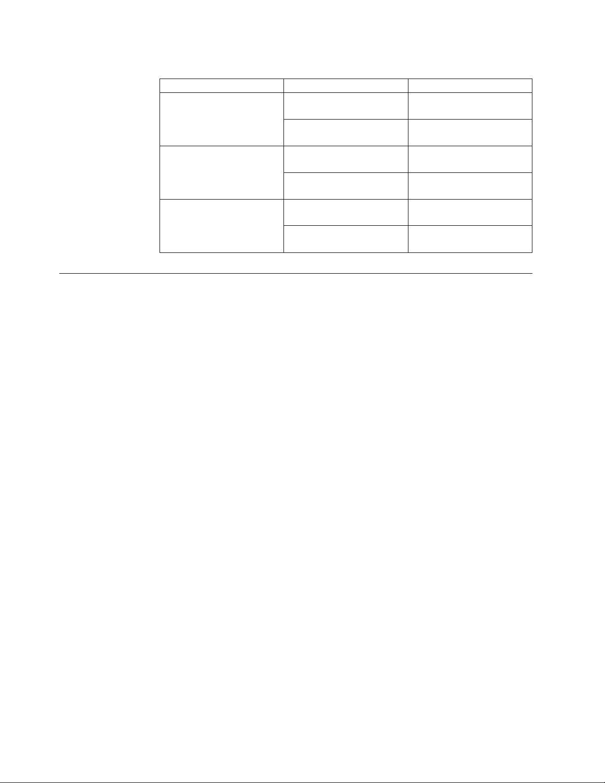
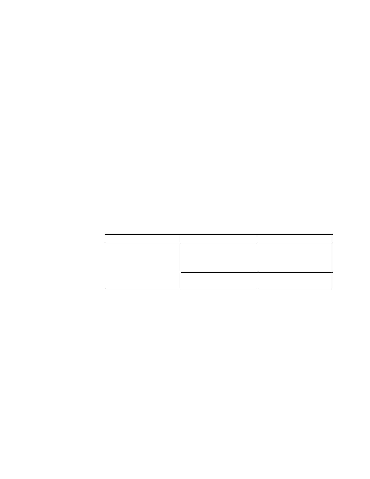
Table 2. IBM c-type SAN switches and directors System LEDs (continued)
LED Status Description
SUP Green Supervisor modules are
FAB Green Fabric modules are
IOM Green Switching modules are
Supervisor Modules
This section describes supervisor modules supported by different IBM c-type SAN
switches and directors:
v “IBM Supervisor-1E Module”
v “IBM Supervisor-1 Module” on page 16
operational.
Amber At least one I/O module has
a red STATUS LED.
operational.
Amber At least one I/O module has
a red STATUS LED.
operational.
Amber At least one I/O module has
a red STATUS LED.
IBM Supervisor-1E Module
The Supervisor-1E Module is designed specifically for the SAN768C-6. This
supervisor module delivers the latest advanced switching technology and resources
to support the 18 slot chassis.
This supervisor module supports the following features:
v Nondisruptive software upgrades
v Stateful process restart and failover
v Fully redundant operation
v Support for up to 768 2/4/8 Gbps, 4/8/16 Gbps, or 8/16/32 Gbps full line-rate
autosensing Fibre Channel ports in a single chassis
v Support for up to 48 Tbps of Fibre Channel system bandwidth
v Multipathing based on Fabric Shortest Path First (FSPF)
v Ability to dynamically reroute traffic in the event of a switch failure
v Network management through the command-line interface (CLI) and through
Data Center Network Manager (DCNM)
v Extensive security features including RADIUS and TACACS+, Fibre Channel
Security Protocol (FC-SP), Secure File Transfer Protocol (SFTP), Secure Shell
(SSH) Protocol, and Simple Network Management Protocol Version 3 (SNMPv3)
implementing Advanced Encryption Standard (AES), VSANs, hardware-enforced
zoning, ACLs, and per-VSAN role-based access control (RBAC)
v Support for virtual SAN (VSAN) technology and inter-VSAN routing (IVR)
v Network services such as access control lists (ACLs) and quality of service (QoS)
v Smart zoning
v Power-on self-test (POST) and diagnostics
v Switched Port Analyzer (SPAN) and Remote Switched Port Analyzer (RSPAN)
12 SAN192C-6, SAN384C-6 and SAN768C-6 Installation, Service, and User Guide
Page 37

Figure 7 shows the IBM c-type SAN switches and directors Supervisor-1E Module.
Figure 7. IBM Supervisor-1E Module
1. Module retaining screw
2. ID: locator LED
3. Link: management port link status LED
4. MGMT Ethernet: system out of band Ethernet management port
5. ACT: management port packet activity LED
6. Console Serial Port: module serial console port
7. Eject Request: eject request button for USB1 device
8. USB1: usb1 status LED
9. USB1 USB port
10. Slot0: slot0 status LED
11. Eject Request: eject request button for slot0 device
12. Reset: module reset button
13. Module lock release button
14. Status: system diagnostic test status LED
15. System: system environment status LED
16. Active: supervisor redundancy status LED
17. PWR MGMT: system power status LED
18. Management port operational status LED
19. Module ejection lever
20. Slot0 USB port
Table 3 on page 14 describes the LEDs on the IBM c-type SAN switches and
directors Supervisor-1E Module.
Chapter 1. Introducing the IBM c-type SAN Directors 13
Page 38

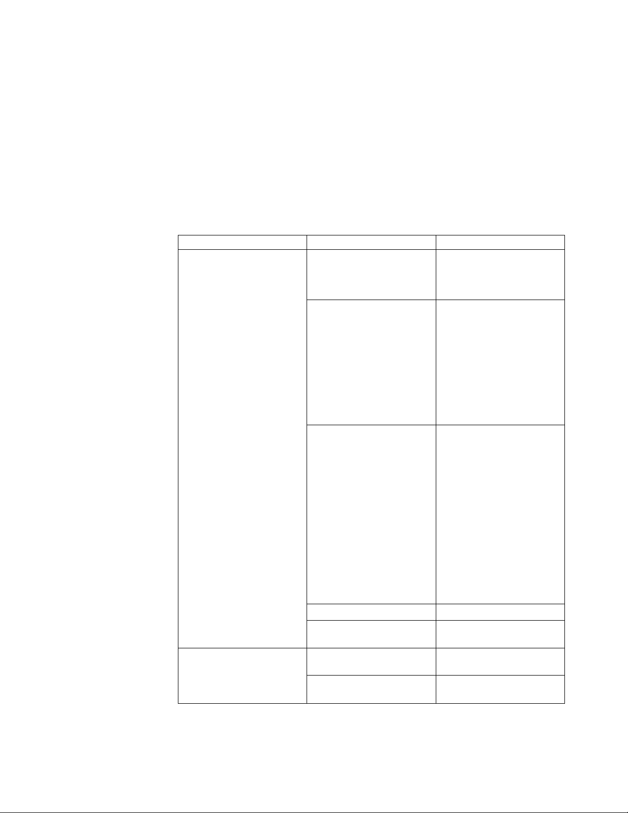
Table 3. IBM Supervisor-1E Module LEDs
LED Status Description
ID Flashing blue A user has activated this
LED to allow a person to
find this module in the
chassis.
Off Location identification is
deactivated for this module.
Status Green All module diagnostics
passed. The module is
operational.
Red The module has detected an
error and cannot power on
or boot up.
The module is not properly
inserted.
A bootup or runtime
diagnostic test has failed.
Flashing Red Indicates one of the
following conditions:
The temperature of the
module has exceeded the
safe operating temperature
limits (a major temperature
alarm has occurred). The
module has been shut down
to prevent permanent
damage. The system will be
shut down after two minutes
if this condition is not
cleared.
Off The module is not receiving
System Green All environmental sensors in
Amber At least one power supply
Red The temperature of the
Off The slot has detected a slot
14 SAN192C-6, SAN384C-6 and SAN768C-6 Installation, Service, and User Guide
The module is resetting.
The ejector lever is open.
power.
the system are within
operational bounds.
has failed or the power
supply fan has failed.
supervisor module exceeded
the major threshold.
ID parity error
Page 39

Table 3. IBM Supervisor-1E Module LEDs (continued)
LED Status Description
Active Green The supervisor is operational
and in HA active state.
Amber The supervisor module is in
HA standby state.
Power Management Green There is sufficient power
available for all installed
modules.
Amber There is insufficient power
for all installed modules.
MGMT Ethernet Green The mgmt0 interface is
administratively active and
the supervisor is in HA
active state.
Amber The mgmt0 interface is
administratively active and
the supervisor is in the HA
standby state.
Flashing amber The management port link is
bad and has been disabled
due to a hardware failure.
Off The mgmt0 interface is
uninitialized. No signal is
detected.
ACT Flashing Green Frames are being transmitted
or received by the interface.
Off There is no activity on the
interface.
Link Green The management port link is
operational.
Off No link signal received.
LOG FLASH Green The log flash CompactFlash
or USB disk is being
accessed. Do not remove the
media until the LED is off..
Off The expansion flash
CompactFlash or USB disk is
not being accessed. You can
remove the media while this
LED is off.
Slot0 Green The log flash CompactFlash
or USB disk is being
accessed. Do not remove the
media until the LED is off.
Off The expansion flash
CompactFlash or USB disk is
not being accessed. You can
remove the media while this
LED is off.
Chapter 1. Introducing the IBM c-type SAN Directors 15
Page 40

IBM Supervisor-1 Module
The IBM Supervisor-1 Module is designed specifically for the SAN192C-6 and
SAN384C-6 chassis. This supervisor module provides control and management
functions for the switch and enables high-performance switching.
This supervisor module supports the following features:
v Nondisruptive software upgrades
v Stateful process restart and failover
v Fully redundant operation
v Support for up to 384 Fibre Channel ports in a single chassis and 1152 Fibre
Channel ports in a single rack
v Support for up to 24 Tbps of Fibre Channel system bandwidth
v Multipathing based on Fabric Shortest Path First (FSPF)
v Ability to dynamically reroute traffic in the event of a switch failure
v Network management through the command-line interface (CLI) and through
Data Center Network Manager (DCNM)
v Extensive security features including RADIUS and TACACS+, Fibre Channel
Security Protocol (FC-SP), Secure File Transfer Protocol (SFTP), Secure Shell
(SSH) Protocol, and Simple Network Management Protocol Version 3 (SNMPv3)
implementing Advanced Encryption Standard (AES), VSANs, hardware-enforced
zoning, ACLs, and per-VSAN role-based access control
v Support for virtual SAN (VSAN) technology and inter-VSAN routing (IVR)
v Network services such as access control lists (ACLs) and quality of service
(QoS)
v Smart zoning
v Power-on self-test (POST) and diagnostics
v Switched Port Analyzer (SPAN) and Remote Switched Port Analyzer (RSPAN)
Figure 8 shows the IBM c-type SAN switches and directors Supervisor-1 module.
Figure 8. IBM Supervisor-1 Module
1. Module retaining screw
2. ID: locator LED
16 SAN192C-6, SAN384C-6 and SAN768C-6 Installation, Service, and User Guide
Page 41
3. Link: management port link status LED
4. MGMT Ethernet: system out of band Ethernet management port
5. ACT: management port packet activity LED
6. Console Serial Port: module serial console port
7. Eject Request: eject request button for USB1 device
8. USB1: usb1 status LED
9. USB1 USB port
10. Slot0: slot0 status LED
11. Eject Request: eject request button for slot0 device
12. Reset: module reset button
13. Module lock release button
14. Status: system diagnostic test status LED
15. System: system environment status LED
16. Active: supervisor redundancy status LED
17. PWR MGMT: system power status LED
18. Management port operational status LED
19. Module ejection lever
20. Slot0 USB port
Table 4 describes the LEDs on the IBM c-type SAN switches and directors
Supervisor-1 Module.
Table 4. IBM Supervisor-1 Module LEDs
LED Status Description
ID Flashing blue A user has activated this
LED to allow a person to
find this module in the
chassis.
Off Location identification is
deactivated for this module.
Chapter 1. Introducing the IBM c-type SAN Directors 17
Page 42

Table 4. IBM Supervisor-1 Module LEDs (continued)
LED Status Description
Status Green All module diagnostics
passed. The module is
operational.
Red Indicates one of the
following conditions:
The module has detected an
error and cannot power on
or boot up.
The module is not properly
inserted.
A bootup or runtime
diagnostic test has failed.
Flashing Red Indicates one of the
following conditions:
The temperature of the
module has exceeded the
safe operating temperature
limits (a major temperature
alarm has occurred). The
module has been shut down
to prevent permanent
damage. The system will be
shut down after two minutes
if this condition is not
cleared.
The module is resetting.
The ejector lever is open.
Off The module is not receiving
power.
System Green All environmental sensors in
the system are within
operational bounds.
Amber At least one power supply
has failed or the power
supply fan has failed.
Red The temperature of the
supervisor module exceeded
the major threshold.
Active Green The supervisor is operational
and in HA active state.
Amber The supervisor module is in
HA standby state.
Power Management Green There is sufficient power
available for all installed
modules.
Amber There is insufficient power
for all installed modules.
18 SAN192C-6, SAN384C-6 and SAN768C-6 Installation, Service, and User Guide
Page 43

Table 4. IBM Supervisor-1 Module LEDs (continued)
LED Status Description
MGMT Ethernet Green The mgmt0 interface is
administratively active and
the supervisor is in HA
active state.
Amber The mgmt0 interface is
administratively active and
the supervisor is in the HA
standby state.
Off The mgmt0 interface is
uninitialized. No signal is
detected.
ACT Green Frames are being transmitted
or received by the interface.
Off There is no activity on the
interface.
Link Green The management port link is
operational.
Amber The management port link
has been disabled by
software.
Flashing amber The management port has
been disabled by a hardware
fault.
Off No link signal received.
USB1 Green The flash device is mounted.
Red The device is a valid device
type, but failed to be
mounted. This can be due to
an invalid file system format.
Off The flash device is not
mounted and can be safely
removed.
Slot0 Green The flash device is mounted.
Red The device is a valid device
type, but failed to be
mounted. This can be due to
an invalid file system format.
Off The flash device is not
mounted and can be safely
removed.
Crossbar Fabric Modules
This section describes the crossbar fabric modules supported by different IBM
c-type SAN director switches:
v “SAN768C-6 Crossbar Fabric Modules” on page 20
v “SAN384C-6 Crossbar Fabric Modules” on page 22
v “SAN192C-6 Crossbar Fabric Modules” on page 24
Chapter 1. Introducing the IBM c-type SAN Directors 19
Page 44

SAN768C-6 Crossbar Fabric Modules
The SAN768C-6 supports up to six crossbar fabric modules. There is a crossbar
fabric module designed specifically for the SAN768C-6. The crossbar fabric
modules are installed vertically in slots 21 through 26, numbered from left to right,
at the back of the chassis behind the fan modules.
Figure 9. SAN768C-6 Crossbar Fabric Module
1. Locking lever
2. Unlocking button
3. Fabric module LEDs
20 SAN192C-6, SAN384C-6 and SAN768C-6 Installation, Service, and User Guide
Page 45

4. Connector pins
The fan modules cover the fabric modules in the back of the chassis. Fan module 1
must be removed to access fabric modules 1 and 2, fan module 2 must be removed
to access fabric modules 3 and 4, and fan module 3 must be removed to access
fabric modules 5 and 6.
The LEDs on the crossbar fabric modules indicate the status of the modules.
Table 5 describes the LEDs.
Table 5. SAN768C-6 Crossbar Modules LEDs
LED Status Description
Status Green All diagnostics pass. The
module is operational
(normal initialization
sequence).
Red Indicates one of the
following: The diagnostic test
has failed. The module is not
operational because a fault
has occurred during the
initialization sequence.
The inlet air temperature of
the system has exceeded the
safe operating temperature
limits of the card (a major
environmental warning). The
card has been shut down to
prevent permanent damage.
Flashing Red Indicates one of the
following: The fabric module
has just been inserted and is
booting up.
An overtemperature
condition has occurred and
the module has powered
down.
The power was turned off
with a CLI command. The
module is resetting and both
ejector levers are out.
Off The module is not receiving
power.
Locater ID Flashing Blue The operator has activated
this LED to identify this
module in the chassis.
Off Operator has not flagged this
card for identification.
Chapter 1. Introducing the IBM c-type SAN Directors 21
Page 46

SAN384C-6 Crossbar Fabric Modules
The SAN384C-6 supports up to six crossbar fabric modules. There is a crossbar
fabric module designed specifically for the SAN384C-6. The crossbar fabric
modules are installed vertically in slots 21 through 26, numbered from left to right,
at the back of the chassis behind the fan modules. A minimum of 3 crossbar fabric
modules are required to deliver full line rate and bandwidth for the switch. A
fourth crossbar fabric module is required for N+1 protection.
Figure 10. SAN384C-6 Crossbar Fabric Module
1. Locking lever
2. Unlocking button
3. Fabric module LEDs
4. Connector pins
22 SAN192C-6, SAN384C-6 and SAN768C-6 Installation, Service, and User Guide
Page 47
Each crossbar fabric module connects to 8 switching modules and 2 supervisor
modules. In addition, each crossbar fabric module supports four 55 Gbps fabric
ports connected to each switching module and one 55 Gbps fabric port connected
to each supervisor module.
The fan modules cover the fabric modules in the back of the chassis. Fan module 1
must be removed to access fabric modules 1 and 2, fan module 2 must be removed
to access fabric modules 3 and 4, and fan module 3 must be removed to access
fabric modules 5 and 6.
The LEDs on the crossbar fabric modules indicate the status of the modules.
Table 6 describes the LEDs.
Table 6. SAN384C-6 Crossbar Modules LEDs
LED Status Description
Status Green All diagnostics pass. The
module is operational
(normal initialization
sequence).
Orange One of the following occurs:
The module is booting or
running diagnostics (normal
initialization sequence).
An over-temperature
condition occurred (a minor
threshold was exceeded
during environmental
monitoring).
Red, flashing One of the following occurs:
The diagnostic test failed.
The module is not
operational because a fault
occurred during the
initialization sequence.
An over-temperature
condition occurred (a major
threshold was exceeded
during environmental
monitoring).
Fabric module has been
manually powered off.
Red Bad slot ID parity.
Off The module is not receiving
power.
Locater ID Blue flashing Operator has flagged this
card for identification.
Off Operator has not flagged this
card for identification.
Since the crossbar fabric modules are located behind the fan modules in the
chassis, the LEDs on the crossbar fabric module are not easily visible from the back
Chapter 1. Introducing the IBM c-type SAN Directors 23
Page 48

of the chassis. So, crossbar fabric status LEDs are provided on the fan modules as
well. Since each fan module covers two fabric modules, the status LEDs for two
crossbar fabric modules are present on each fan module. If the fan module is
removed the status and locator LEDs on crossbar fabric modules will be visible.
When a fabric module needs to be located, the locator LED of the corresponding
fan module needs to be activated, followed by the locator LED of fabric module,
using CLIs locator-led fan <fan module number> and locator-led xbar <xbar
slot number>. For example, to locate crossbar fabric module 4, the locator LED of
fan module 2 needs to be activated followed by the locator LED of fabric module
4.
SAN192C-6 Crossbar Fabric Modules
The SAN192C-6 supports up to six crossbar fabric modules. There is a crossbar
fabric module designed specifically for the SAN192C-6. The crossbar fabric
modules are installed vertically at the back of the chassis behind the fan modules.
Fabric slots 1 and 2 are behind fan module slot 1, fabric slots 3 and 4 are behind
fan module slot 2, and fabric slots 5 and 6 are behind fan module slot 3.
24 SAN192C-6, SAN384C-6 and SAN768C-6 Installation, Service, and User Guide
Page 49

Figure 11. SAN192C-6 Crossbar Fabric Module
1. Locking lever
2. Unlocking button
3. Fabric module LEDs
4. Connector pins
The LEDs on the crossbar fabric modules indicate the status of the modules.
Table 7 on page 26 describes the LEDs.
Chapter 1. Introducing the IBM c-type SAN Directors 25
Page 50

Table 7. SAN192C-6 Crossbar Modules LEDs
LED Status Description
Status Green All diagnostics pass. The
module is operational
(normal initialization
sequence).
One of the following occurs:
The module is booting or
running diagnostics (normal
initialization sequence).
An over-temperature
condition occurred (a minor
threshold was exceeded
during environmental
monitoring).
Red, flashing One of the following occurs:
The diagnostic test failed.
The module is not
operational because a fault
occurred during the
initialization sequence.
An over-temperature
condition occurred (a major
threshold was exceeded
during environmental
monitoring).
Fabric module has been
manually powered off.
Red Bad slot ID parity.
Off The module is not receiving
power.
Locater ID Blue flashing Operator has flagged this
card for identification.
Off Operator has not flagged this
card for identification.
Each crossbar fabric module connects to 4 switching modules and 2 supervisor
modules. In addition, each crossbar fabric module supports four 55 Gbps fabric
ports connected to each switching module and one 55 Gbps fabric port connected
to each supervisor module.
Since the crossbar fabric modules are located behind the fan modules in the
chassis, the LEDs on the crossbar fabric module are not easily visible from the back
of the chassis. So, crossbar fabric status LEDs are provided on the fan modules as
well. Since each fan module covers two fabric modules, the status LEDs for two
crossbar fabric modules are present on each fan module. If the fan module is
removed the status and locator LEDs on crossbar fabric modules will be visible.
26 SAN192C-6, SAN384C-6 and SAN768C-6 Installation, Service, and User Guide
Page 51

When a fabric module needs to be located, the locator LED of the corresponding
fan module needs to be activated, followed by the locator LED of fabric module,
using CLIs locator-led fan <fan module number> and locator-led xbar <xbar
slot number>. For example, to locate crossbar fabric module 4, the locator LED of
fan module 2 needs to be activated followed by the locator LED of fabric module
4.
Fibre Channel Switching Modules
This section describes “IBM 48 port 32 Gbps Fibre Channel Switching Module”
supported by the IBM c-type SAN switches and directors switches.
IBM 48 port 32 Gbps Fibre Channel Switching Module
The IBM 48 port 32 Gbps Fibre Channel switching module is designed specifically
for the IBM c-type SAN directors.
With 768 line-rate 32 Gbps Fibre Channel ports per director, the 32 Gbps 48 port
Fibre Channel switching module meets the high-performance needs for
flash-memory and Non-Volatile Memory Express (NVMe) over Fibre Channel
workloads. The switching module is hot swappable and compatible with 4 Gbps, 8
Gbps, 16 Gbps, and 32 Gbps Fibre Channel interfaces. This module also supports
hot swappable Enhanced Small Form-Factor Pluggable (SFP+) transceivers.
Individual ports can be configured with 32 Gbps, 16 Gbps, 8 Gbps and 4 Gbps
SFP+ transceivers. Each port supports 500 buffer credits for exceptional
extensibility without the need for additional licenses. With the Enterprise Package
license, up to 8191 buffer credits can be allocated to an individual port, enabling
full link bandwidth over long distances with no degradation in link utilization.
For more information on the IBM 48 port 32 Gbps Fibre Channel Switching
Module, see the IBM 48-Port 32-Gbps Fibre Channel Switching Module Data Sheet.
Figure 12 shows a IBM 48 port 32 Gbps Fibre Channel Switching Module.
Figure 12. IBM 48 port 32 Gbps Fibre Channel Switching Module
1. Captive screw
2. Unlock button
3. Unlocking lever
4. Status LED
5. ID LED
6. Fibre Channel ports
7. Link LEDs
8. Fibre Channel port group
Chapter 1. Introducing the IBM c-type SAN Directors 27
Page 52

LEDs on the 48 port 32 Gbps Fibre Channel Switching Modules
Table 8 describes the LEDs for the 48 port 32 Gbps Fibre Channel switching
module.
Table 8. IBM 48 Port 32 Gbps Fibre Channel Switching Module LEDs
LED Status Description
Status Green All diagnostics pass. The
module is operational
(normal initialization
sequence).
Orange One of the following occurs
or occurred:
The module is booting or
running diagnostics (normal
initialization sequence).
An over temperature
condition has occurred. (A
minor temperature threshold
has been exceeded during
environmental monitoring.)
Blinking Red One of the following occurs:
The module is resetting. The
switch has been powered on
or the module has been hot
inserted during the normal
initialization sequence.
An over temperature
condition has occurred. (A
major temperature threshold
has been exceeded during
environmental monitoring.)
If the module fails to
download code and
configuration information
successfully during the initial
reset, the LED stays blinking
red; the module does not
come online.
Solid Red The module has detected a
slot ID parity error on the
mid plane. The module
cannot determine its slot
number and will not respond
to the supervisor.
Off The module is not receiving
power.
ID Flashing blue Identifier LED. The operator
has selected this module for
service from the CLI.
Off This module is not selected.
28 SAN192C-6, SAN384C-6 and SAN768C-6 Installation, Service, and User Guide
Page 53

Table 8. IBM 48 Port 32 Gbps Fibre Channel Switching Module LEDs (continued)
LED Status Description
Link Green The port is active (the link is
SAN Extension Modules
This section describes the SAN Extension modules supported by the IBM c-type
SAN switches and directors switches:
v “IBM c-type SAN Director 24/10 port SAN Extension Module”
v “LEDs on the 24/10 Port SAN Extension Module” on page 30
IBM c-type SAN Director 24/10 port SAN Extension Module
The IBM c-type SAN Director 24/10 port SAN Extension Module provides a high
performance, flexible, unified platform for deploying enterprise class disaster
recovery and business continuance SAN extension solutions. The MDS 24/10 port
SAN Extension Module is supported on IBM c-type SAN switches and directors.
With 24 line rate 2-, 4-, 8-, 10-, and 16 Gbps Fibre Channel ports and eight 1 and
10GE or two 40GE Fibre Channel over IP (FCIP) ports, this module enables large
and scalable deployment of SAN extension solutions. The SAN extension module
has two independent service engines that can each be individually and
incrementally enabled to scale as business requirements expand. The SAN
extension module supports the full range of services available on other IBM c-type
SAN Director Fibre Channel switching modules, including virtual SAN (VSAN),
security, and traffic management services. The FCIP module uses IBM expertise
and knowledge of IP networks to deliver outstanding SAN extension performance,
reducing latency for disk and tape operations with FCIP acceleration features,
including FCIP write acceleration and FCIP tape write and read acceleration.
Hardware-based encryption helps secure sensitive traffic with IP Security (IPsec),
and hardware-based compression dramatically enhances performance for both high
and low speed links, enabling immediate cost savings in expensive WAN
infrastructure. Multiple FCIP interfaces within a single engine or across service
engines can be grouped into a port channel of up to 16 links for high availability
and increased aggregate throughput.
connected and operational).
Orange The module or port is
disabled through the CLI
command or the module is
initializing.
Blinking Orange The port is faulty and has
been disabled.
Off The port is not active or the
link is not connected.
For more information on the IBM c-type SAN Director 24/10 Port SAN Extension
Module, see the IBM c-type SAN Director 24/10 port SAN Extension Module for
IBM c-type SAN Switches and Directors Datasheet.
Note: In NX-OS Release 7.3(0)DY(1), 40GE IP Storage interfaces are not supported.
Figure 13 on page 30 shows a IBM c-type SAN Director 24/10 Port SAN Extension
Module.
Chapter 1. Introducing the IBM c-type SAN Directors 29
Page 54

Figure 13. IBM c-type SAN Director 24/10 Port SAN Extension Module
1. Captive screw
2. Unlock button
3. Unlocking lever
4. Status LED
5. ID LED
6. FCIP ports
7. Link LEDs
8. FCIP port group
LEDs on the 24/10 Port SAN Extension Module
Table 9 describes the LEDs for the 24/10 port SAN Extension module.
Table 9. IBM c-type SAN switches and directors 24/10 Port SAN Extension Module LEDs
LED Status Description
30 SAN192C-6, SAN384C-6 and SAN768C-6 Installation, Service, and User Guide
Page 55

Table 9. IBM c-type SAN switches and directors 24/10 Port SAN Extension Module
LEDs (continued)
Status Green All diagnostics pass. The
module is operational
(normal initialization
sequence).
Orange One of the following occurs
or occurred:
The module is booting or
running diagnostics (normal
initialization sequence).
An over temperature
condition has occurred. (A
minor temperature threshold
has been exceeded during
environmental monitoring.)
Blinking Red One of the following occurs:
The module is resetting. The
switch has just been powered
on or the module has been
hot inserted during the
normal initialization
sequence.
An over temperature
condition has occurred (a
major temperature threshold
has been exceeded during
environmental monitoring).
If the module fails to
download the code and
configuration information
successfully during the initial
reset, the LED stays blinking
red; the module does not
come online.
Solid Red The module has detected a
slot ID parity error on the
mid plane. The module can
not determine its slot
number and hence will not
respond to the Supervisor.
ID Flashing blue The operator has activated
this LED to identify this
module in the chassis.
Off This module is not being
identified.
Chapter 1. Introducing the IBM c-type SAN Directors 31
Page 56

Fan Modules
Table 9. IBM c-type SAN switches and directors 24/10 Port SAN Extension Module
LEDs (continued)
Link Solid green Link is up.
Steady Flashing Green Port Beacon On (beacon is
used to identify port).
Intermittent Flashing Green Link is up (traffic on port).
Solid Orange SFP not present or admin is
down.
Flashing Orange A fault condition exists.
Off The port is not active or the
link is not connected.
This section describes the fan modules present in the IBM c-type SAN switches
and directors.
One fan can fail without affecting the thermal performance of the system.
Redundant fan controllers and other internal mechanisms are in place to ensure
that any single fan module does not go down.
Any single fan can fail and the system continues to operate under all conditions.
Two fan failures might cause alarms from ASIC when temperature exceeds the
threshold. At 86 degrees F (30° C) or less, a single fan module can be removed and
the system can continue to operate up to 72 hours to allow for replacement of a
failed fan module. When the temperature exceeds the threshold, the device
automatically shuts down in 3 minutes.
SAN768C-6 Fan Modules
The SAN768C-6 has three fan modules, each with six fans, that are installed
vertically at the back of the chassis. Each fan module can be removed while the
other two fan modules continue to move air through the chassis.
The fan modules cover the fabric modules in the back of the chassis. Fan module 1
must be removed to access fabric modules 1 and 2, fan module 2 must be removed
to access fabric modules 3 and 4, and fan module 3 must be removed to access
fabric modules 5 and 6.
32 SAN192C-6, SAN384C-6 and SAN768C-6 Installation, Service, and User Guide
Page 57

Figure 14. SAN768C-6 Fan Modules External and Internal View
1. Fan handles
2. Fan module status LED
3. Fan module ID LED
4. Left fabric module status LED
5. Right fabric module status LED
6. Fans (6)
7. Fan module connectors
SAN384C-6 Fan Modules
The SAN384C-6 has three fan modules, each with four fans, that are installed
vertically at the back of the chassis. Each fan module can be removed while the
other two fan modules continue to move air through the chassis.
The fan modules cover the fabric modules in the back of the chassis. Fan module 1
must be removed to access fabric modules 1 and 2, fan module 2 must be removed
to access fabric modules 3 and 4, and fan module 3 must be removed to access
fabric modules 5 and 6.
Figure 15 on page 34 shows the front and rear view of a SAN384C-6 fan module.
Chapter 1. Introducing the IBM c-type SAN Directors 33
Page 58

Figure 15. SAN384C-6 Fan Modules External and Internal View
1. Left fabric module status LED
2. Fan module status LED
3. Fan module ID LED
4. Right fabric module status LED
5. Fans (4)
6. Fan module connectors
SAN192C-6 Fan Modules
The SAN192C-6 has three fan modules, each with two fans, that are installed
vertically at the back of the chassis. Each fan module can be removed while the
other two fan modules continue to move air through the chassis.
The fan modules cover the fabric modules in the back of the chassis. Fan module 1
must be removed to access fabric modules 1 and 2, fan module 2 must be removed
to access fabric modules 3 and 4, and fan module 3 must be removed to access
fabric modules 5 and 6.
34 SAN192C-6, SAN384C-6 and SAN768C-6 Installation, Service, and User Guide
Page 59

Figure 16. SAN192C-6 Fan Modules External and Internal View
1. Left fabric module status LED
2. Fan module status LED
3. Fan module ID LED
4. Right fabric module status LED
5. Fans (4)
6. Fan module connectors
Power Supplies
The IBM c-type SAN switches and directors supports the following types of power
supplies:
v 3000 W AC power supply (AC input and DC output)
v 3000 W DC power supply (DC input and DC output)
The SAN768C-6 supports up to 16 hot-swappable 3000 W AC or DC power
supplies. The SAN384C-6 supports up to eight hot-swappable 3000 W AC power
supplies (AC input). The SAN192C-6 supports up to four hot-swappable 3000 W
AC power supplies (AC input).
The 3000 W AC power supply unit may be connected to either 220 V or 110 V AC
power sources. When connected to 220 V each PSU has a maximum output
capacity of 3000 W. When connected to 110 V each PSU has a maximum output
capacity of 1450 W.
Each power supply module monitors its output voltage and provides the status to
the supervisor. In addition, the power supply modules provide information about
local fans, power, shutdown control, and E2PROM to the supervisor.
Chapter 1. Introducing the IBM c-type SAN Directors 35
Page 60

Note: The minimum number of AC PSUs required to achieve grid redundancy on
each of the IBM c-type SAN switches and directors differ. For more information see
the AC Power Supply Requirements for Grid Redundancy section.
When PSUs are in 1450 W mode and the system is configured in redundant power
mode, the total power available to the system may not be sufficient to power all
modules installed in the chassis. For more information, refer to the Cisco NX-OS
Fundamentals Configuration Guide.
Starting from NX-OS Release 6.2(19), all NX-OS 6.2(x) releases support a 3500 W
high voltage DC (HVDC) power supply unit on SAN192C-6 and SAN384C-6
Directors.
Figure 17. 3000 W AC Power Supply
1. Power supply switch
2. Power module handle
3. AC power connection
4. Unlocking lever
5. Power cable retainer
6. Power module LEDs
36 SAN192C-6, SAN384C-6 and SAN768C-6 Installation, Service, and User Guide
Page 61

Figure 18. 3000 W DC Power Supply
1. Power supply switch
2. Negative terminals
3. Positive terminals
4. Power module LEDs
5. Power supply handle
6. Power supply exhaust
7. Unlocking lever
Table 10 describes the power supply LEDs for the IBM c-type SAN switches and
directors.
Table 10. Power Supply LEDs
LED Status Description
Input 1 Green The AC or DC input voltage
Input 2 (available only on
DC power supply units)
Output Green The AC or DC output power
is within the valid range.
Off The AC or DC input voltage
is outside the valid range.
Green The DC input voltage is
within the valid range.
Off The DC input voltage is
outside the valid range.
is within the valid range.
Off The AC or DC output power
is outside the valid range.
Chapter 1. Introducing the IBM c-type SAN Directors 37
Page 62

Table 10. Power Supply LEDs (continued)
LED Status Description
Fault Red, blinking (The blinking
ID Blue, blinking The operator has activated
Power Modes
A c-type SAN Director has a flexible power system.
Any operational power supply provides power to the system power bus. This
allows the power load of the system to be shared equally across all operational
power supplies.
Power supply output can be allocated to one of two pools. The available pool is
available to bring up system components. The reserve pool is kept in reserve and
not counted towards the available power.
Self-diagnostic tests have
stops when the fault
condition is cleared.)
Off The AC or DC output
Off This module is not being
failed or another power
supply failure has occurred.
voltage and power supply
unit tests are okay.
this LED to identify this
module in the chassis.
identified.
The system can be configured in one of several modes which vary the size of the
available and reserve power pools, according to user requirements.
Combined mode
This mode allocates the output power of all power supplies to available power for
switch operations. This mode does not reserve any output power in case of power
outages or power supply failures.
Power supply redundancy mode (N+1)
In this mode one power supply's output is allocated to the reserve power pool.
This provides the system with enough reserve power in case a single power
supply fails. The remaining power supplies are allocated to the available power
pool. The reserve power supply must be at least as powerful as the most powerful
power supply in the available pool to potentially replace the full power output of
the failed power supply in the worst case. Because it is impossible to predict which
power supply may fail, we recommend provisioning the system with power
supplies of equal rating. This way the output of any power supply that fails can be
replaced by the remaining power supplies.
For example, a system with four 3 kW power supplies in N+1 redundancy mode
has a total of 12 kW. 9 kW are allocated to the available power pool and 3 kW are
reserved. If any of the power supplies fail enough power is reserved that the
remaining power supplies can still meet the 9 kW commitment.
Input grid redundancy mode (grid redundancy)
In this mode half of the power supply's output is allocated to the reserve power
pool and half to the available power pool. This provides the system with enough
reserve power in the case of 50% of the power supplies failing, as when a power
grid fails. The system logically allocates the left two columns of PSU bays to Grid
38 SAN192C-6, SAN384C-6 and SAN768C-6 Installation, Service, and User Guide
Page 63

A and sums the output power of operational PSUs. It does the same for the right
two columns (Grid B) and uses the minimum of the two as the available power
pool. To utilize maximum power the sum of power supply outputs of Grid A and
Grid B PSU bays must be equal.
For example, a system with four 3 kW PSUs in Grid A bays and three 3 kW PSUs
in Grid B bays and in grid redundancy mode has 12 kW available from Grid A and
9 kW from Grid B. The minimum of the two grids is 9 kW so 9 kW is allocated to
the available power pool and 9 kW are reserved. If either grid fails enough power
is reserved that the remaining power supplies can still meet the 9 kW commitment.
The output of the fourth PSU in Grid A is not considered in the calculations even
though it provides power.
Full redundancy mode
This mode supports both grid redundancy or N+1 redundancy. 50% of the power
supply output is allocated to the reserve pool and the other 50% of the power
supply outputs are allocated to the available power pool. The reserved power may
be used to backup either single power supply failures or a grid failure.
For example, a system with six 3 kW power supplies in grid redundancy mode has
a total of 18 kW. 9 kW are allocated to the available power pool and 9 kW are
allocated to the reserve pool. If a grid failure occurs (half of the power supplies
loose power) the full reserve power pool is available to meet the 9 kW
commitment. Otherwise, as single power supplies fail power is allocated to the
available pool from the remaining reserve power pool until the reserve power pool
is exhausted.
Note: Once a single power supply has failed in this mode, grid redundancy is no
longer available.
Figure 19 shows how to connect power supplies in a SAN768C-6 for grid
redundancy
Figure 19. SAN768C-6 Grid-PSU Connections
Figure 20 on page 40 shows how to connect power supplies in a SAN384C-6 for
grid redundancy
Chapter 1. Introducing the IBM c-type SAN Directors 39
Page 64

Figure 20. SAN384C-6 Grid-PSU Connections
Figure 21 shows how to connect power supplies in a SAN192C-6 for grid
redundancy
Figure 21. SAN192C-6 Grid-PSU Connections
Supported Transceivers
The SAN384C-6 supports the Fibre Channel SFP+ transceivers in either SWL or
LWL.
Fibre Channel SFP+ Transceivers
The transceivers are field-replaceable and hot-swappable. You can use any
combination of SFP+ transceivers that are supported by the switch. The only
restrictions are that SWL transceivers must be paired with SWL transceivers, and
LWL transceivers with LWL transceivers, and the cable must not exceed the
stipulated cable length for reliable communications.
For more information about a specific SFP+ transceiver, see the “SFP+ Transceiver
Specifications” on page 107. SFP+ transceivers can be ordered separately or with
the IBM c-type SAN switches and directors.
Note: Use only Cisco transceivers in the IBM c-type SAN switches and directors.
Each transceiver is encoded with model information that enables the switch to
verify that the transceiver meets the requirements for the switch.
40 SAN192C-6, SAN384C-6 and SAN768C-6 Installation, Service, and User Guide
Page 65

Chapter 2. Rack Installation
This chapter provides information on the rack installation and includes the
following sections:
v “Rack Requirements”
v “Rack-Mounting Guidelines” on page 45
v “Installing and Removing the Brackets” on page 45
v “Installing the Switch on the Brackets” on page 46
Rack Requirements
This section provides the requirements for the following type of racks, assuming
an external ambient air temperature range of 32 to 104 degrees F (0 to 40 degrees
C):
v “General Requirements for Open Four-Post Racks”
v “General Rack and Cabinet Requirements for IBM c-type SAN switches and
directors”
v “Rack and Cabinet Requirements for the SAN768C-6 Chassis” on page 42
v “Rack and Cabinet Requirements for the SAN384C-6 Chassis” on page 42
v “Rack and Cabinet Requirements for the SAN192C-6 Chassis” on page 43
v “Clearance Requirements for IBM c-type SAN switches and directors” on page
43
General Requirements for Open Four-Post Racks
The rack must be a standard 19-inch four-post EIA rack, with mounting rails that
conform to English universal hole spacing per section 1 of ANSI/EIA-310-D-1992.
See the “Clearance Requirements for IBM c-type SAN switches and directors” on
page 43 section.
General Rack and Cabinet Requirements for IBM c-type SAN switches and directors
You can install the following types of racks or cabinets for your switch:
v Standard perforated-doors cabinets
v Solid-walled cabinets with a roof fan module (bottom to top cooling)
v Standard open four-post Telco racks
v Standard open two post Telco racks
Note: IBM c-type SAN switches and directors are compatible with IBM racks and
PDUs.
Use a standard 19 inch, four post Electronic Industries Alliance (EIA) cabinet or
rack with mounting rails that conform to English universal hole spacing per
section 1 of the ANSI/EIA-310-D-1992 standard.
The depth of a four post rack or a cabinet must be 24 to 32 inches (61.0 to 81.3 cm)
between the front and rear mounting vertical rails.
© Copyright IBM Corp. 2018 41
Page 66

Ensure that the airflow and cooling are adequate and there is sufficient clearance
around the air vents on the switch, as described in Appendix A, “Product
Specifications,” on page 99.
The rack must have sufficient vertical clearance for the chassis along with 2 RU for
the shelf brackets, and any desired clearance for the installation process.
The front and rear doors of enclosed racks must have at least 60% open area
perforation pattern.
Additionally, you must consider the following site requirements for the rack:
v Power receptacles must be located within reach of the power cords used with
the switch.
v AC power supplies
v Power cords for 3-kW AC power supplies are 8 to 12 feet (2.5 to 4.3 m) long.
v DC power supplies
v Power cords for 3.0-kW DC power supplies are supplied and dimensioned by
the customer.
v HVAC/HVDC power supplies
v Power cords for 3.5-kW HVAC/HVDC power supplies are 14 feet (4.26 m) long.
v Where necessary, have a seismic rating of Network Equipment Building
Standards (NEBS) Zone 3 or Zone 4, per GR-63-CORE.
Rack and Cabinet Requirements for the SAN768C-6 Chassis
To correctly install the switch in a cabinet located in a hot-aisle/cold-aisle
environment, you should fit the cabinet with baffles to prevent exhaust air from
recirculating into the chassis air intake. Work with your cabinet vendors to
determine which of their cabinets meet the following requirements or see the IBM
Support for recommendations:
v The height of the rack or cabinet must accommodate the 25 RU (43.75 inches or
111.1 cm) height of the switch and its bottom support bracket.
v Minimum gross load rating of 2000 lb (907.2 kg) (static load rating) if supporting
two switches.
Rack and Cabinet Requirements for the SAN384C-6 Chassis
The rack must meet the following requirements:
v The minimum vertical rack space per chassis is 24.5 inches (62.2 cm) or 14 RU.
v The width between the mounting rails must be at least 17.75 inches (45.1 cm).
For four-post EIA racks, this is the distance between the two front rails and rear
rails.
To correctly install the switch in a cabinet located in a hot-aisle/cold-aisle
environment, you should fit the cabinet with baffles to prevent exhaust air from
recirculating into the chassis air intake. Work with your cabinet vendors to
determine which of their cabinets meet the following requirements or see the IBM
Support for recommendations:
v The height of the rack or cabinet must accommodate the 14-RU (24.5 inches or
62.2 cm) height of the switch and its bottom support bracket.
v Minimum gross load rating of 2000 lb (907.2 kg) (static load rating) if supporting
three switches.
42 SAN192C-6, SAN384C-6 and SAN768C-6 Installation, Service, and User Guide
Page 67

Rack and Cabinet Requirements for the SAN192C-6 Chassis
To correctly install the switch in a cabinet located in a hot-aisle/cold-aisle
environment, you should fit the cabinet with baffles to prevent exhaust air from
recirculating into the chassis air intake. Work with your cabinet vendors to
determine which of their cabinets meet the following requirements or see the IBM
Support for recommendations:
v The height of the rack or cabinet must accommodate the 9 RU (15.75 inches or
40.0 cm) height of the switch and its bottom support bracket. The bottom
support bracket ships as a part of the accessory kit for the switch.
v Minimum gross load rating of 2000 lb (907.2 kg) (static load rating) if supporting
four switches.
Clearance Requirements for IBM c-type SAN switches and directors
You must provide adequate clearance between the chassis and any other rack,
device, or structure so that you can properly install the chassis, route cables,
provide airflow, and maintain the switch. Ensure that the following clearance
requirements are met:
v 7 inches (17.78 cm) between the front of chassis and inside of cabinet.
v 34 inches (86.36 cm) [40 inches recommended (101 cm)] in front of the cabinet so
that a fully loaded 34 inches (86.36 cm) chassis box can be moved.
v 2 inches (5.08 cm) for module handles.
v 3 inches (7.62 cm) between the rear of the chassis and the inside of the cabinet,
that is, the perforated rear door (required for airflow in the cabinet if used).
v 25 inches (63.5 cm) outside of the cabinet to remove fabric modules.
v No clearance is required between the chassis and the sides of the rack or cabinet
(no side airflow).
v Clearance required for cables that connect to as many as 400 ports (in addition
to the cabling required for other devices in the same rack). These cables must
not block access to any removable chassis modules or block airflow into or out
of the chassis. Route the cables through the cable management frames on the left
and right sides of the chassis.
Figure 22 on page 44 illustrates the front, rear, and side clearance requirements for
IBM c-type SAN switches and directors:
Chapter 2. Rack Installation 43
Page 68

Figure 22. Clearance Requirements for IBM c-type SAN switches and directors (Top View)
1. Chassis
2. Cable Management Frames
3. Vertical rack-mount posts and rails
4. Area used for fan tray handles at the rear of the chassis (allow 2 inches [5
cm])
5. Nearest object or inside of cabinet (no side clearance required)
6. Fibre Channel ports. Air intake from the cold aisle for all modules and power
supplies
7. Air exhaust to the hot aisle for all modules and power supplies
8. No left side clearance required (no airflow on left side)
9. Chassis width
10. No right side clearance required (no airflow on right side)
11. Rear service clearance required to replace fan trays and fabric modules
12. Airflow clearance area required at the rear of the chassis within the cabinet (if
a cabinet is used)
13. Chassis depth
44 SAN192C-6, SAN384C-6 and SAN768C-6 Installation, Service, and User Guide
Page 69

14. Clearance required between the front of the chassis and the inside of the
cabinet (if used) or the edge of the cold aisle (if no cabinet) for the cable
management frames and the optional front doors
15. Front service clearance required for installing the chassis and replacing the
modules on the front of the chassis
Rack-Mounting Guidelines
CAUTION:
If the rack is on wheels, ensure that the brakes are engaged or the rack is
otherwise stabilized.
CAUTION:
If installing this kit in an EIA rack, attach the switch to all four rack-mounting
rails; the EIA rails may not be thick enough to prevent flexing of the shelf
brackets if only two rails are used.
Before Installing the Rack-Mount Support Brackets
Before installing the rack-mount support brackets for the IBM c-type SAN switches
and directors, check the contents of your kit. Table 11 lists the contents of the shelf
bracket kit.
Table 11. Contents of Rack-Mount Support Brackets Kit
Quantity Part Description
2 Bottom support brackets
20 12-24 x 3/4-in. Phillips screws
20 M6 x 19 mm Phillips binder-head screws
20 10-32 x 3/4-inch screws
Installing and Removing the Brackets
This section provides information on how to install and remove brackets.
Before installing the shelf brackets, check the contents of your kit. Table 12 lists the
contents of the shelf bracket kit.
Table 12. Contents of Shelf Bracket Kit
Quantity Part Description
2 Slider brackets
2 Shelf brackets
1 Crossbar
2 10-32 x 3/8-in. Phillips pan-head screws
16 12-24 x 3/4-in. Phillips screws
16 10-24 x 3/4-in. Phillips screws
Required Equipment
You need the following equipment for this installation:
v Number 2 Phillips screwdriver
v Tape measure and level (to ensure shelf brackets are level)
Chapter 2. Rack Installation 45
Page 70

Installing the IBM c-type SAN Director Shelf Bracket Kit into a Rack
About this task
Figure 23 shows the installation of the IBM c-type SAN Director Shelf Bracket Kit
into a four-post rack.
Figure 23. Installing the Shelf Bracket Kit into a Rack
Use this procedure to install the shelf brackets in a rack.
Procedure
1. Position a shelf bracket inside the rack-mounting rails. Align the screw holes at
the front of the shelf bracket with the holes in the front rack-mounting rail, and
then attach the shelf bracket to the front rack-mounting rail using a minimum
of three (M6, 12-32 or 12-24) screws.
2. Align the screw holes at the back of the shelf bracket with the holes in the back
rack-mounting rail, and then attach the shelf bracket to the back rack-mounting
rail using a minimum three (M6, 12-32 or 12-24) screws.
3. Verify that the shelf brackets are at the same height (using the level or tape
measure as desired).
Installing the Switch on the Brackets
This section provides information on how to install the switch on the rack-mount
support brackets and on the shelf brackets and includes the following subsections:
v “Installing the Switch on the Rack-Mount Support Brackets”
v “Installing the Switch on the Shelf Brackets” on page 47
Installing the Switch on the Rack-Mount Support Brackets
About this task
This topic provides general instructions for installing the switch on top of the
rack-mount support brackets.
46 SAN192C-6, SAN384C-6 and SAN768C-6 Installation, Service, and User Guide
Page 71

Note: This unit is intended for installation in restricted access areas. A restricted
access area can be accessed only by using a special tool, lock and key, or other
means of security.
Note: Only trained and qualified personnel should be allowed to install, replace,
or service this equipment.
Note: Before you install, operate, or service the system, see the IBM Systems Safety
Notices for important safety information.
Use this procedure to install the switch on top of the rack-mount support brackets.
Procedure
1. Verify that the rack-mount support brackets are level and securely attached to
the rack-mounting rails, the support rack-mount support brace is securely
attached to the brackets, and the rack is stabilized.
2. Slide a mechanical lift under the switch and lift the switch up onto the
rack-mount support brackets, ensuring it is squarely positioned.
3. Attach the switch to the rack-mounting rails. See the “Required Equipment” on
page 45.
CAUTION:
We recommend grounding the chassis, even if the rack is already grounded.
There is a grounding pad with two threaded M4 holes on the chassis for
attaching a grounding lug.
Installing the Switch on the Shelf Brackets
This section provides general instructions for installing the switch on top of the
shelf brackets.
About this task
For detailed information about the items required for installation, see the
“Required Equipment” on page 45.
The IBM c-type SAN Director Shelf Bracket Kit can be used to support the switch
in a non-threaded rack. This shelf bracket kit can be used as a permanent support
when installing a IBM c-type SAN Director in a rack that meets the requirements
listed in the “Rack Requirements” on page 41.
Note: This unit is intended for installation in restricted access areas. A restricted
access area can be accessed only by using a special tool, lock and key, or other
means of security.
Note: Only trained and qualified personnel should be allowed to install, replace,
or service this equipment.
Note: Before you install, operate, or service the system, see the IBM Systems Safety
Notices for important safety information.
Use this procedure to install the switch on top of the shelf brackets.
Procedure
1. Verify that the shelf brackets are level and securely attached to the
rack-mounting rails, the crossbar is securely attached to the shelf brackets, and
the rack is stabilized.
Chapter 2. Rack Installation 47
Page 72

2. Slide the switch onto the shelf brackets, ensuring that it is squarely positioned.
3. Attach the IBM c-type SAN director switch to the rack-mounting rails.
a. Slide the clip nuts over the holes on the non threaded rails on the rack.
These clip nuts provide the threading for the screws that will secure the
chassis to the rack.
b. Use the 12 10-32 x 1/2 inch screws provided in this shelf bracket kit to
secure the chassis to the rack. See “Required Equipment” on page 45.
CAUTION:
We recommend that grounding the chassis, even if the rack is already
grounded. There is a grounding pad with two threaded M4 holes on the
chassis for attaching a grounding lug.
Removing the Shelf Bracket Kit
About this task
The shelf bracket kit can be removed after the IBM c-type SAN director switch has
been installed in a two-post telco (only SAN192C-6 Director) or four-post EIA rack,
and the front rack-mount brackets are securely attached to the rack-mounting rails.
For additional support in an EIA rack, ensure that the C brackets on the
SAN384C-6 Switch are attached to the rear rack-mounting rails.
Use this procedure to remove the shelf bracket kit.
Procedure
1. Remove the screws fastening the slider brackets to the rear rack-mounting rails.
Then slide the slider brackets out of the shelf brackets.
2. Remove the screws fastening the crossbar to the shelf brackets and remove the
crossbar.
3. Remove the screws fastening the shelf brackets to the front rack-mounting rails.
Then remove the shelf brackets from the rack.
48 SAN192C-6, SAN384C-6 and SAN768C-6 Installation, Service, and User Guide
Page 73

Chapter 3. Installing the IBM c-type SAN Device
This chapter describes how to install the IBM c-type SAN Device chassis and its
components, and includes the following information:
v “Attaching Bottom-Support Rails to a Four-Post Rack” on page 53
v “Attaching Bottom-Support Rails to a Four-Post Rack” on page 53
v “Attaching Bottom-Support Rails to a Two-Post Rack for the SAN192C-6
Director” on page 52
v “Installing the SAN384C-6 or SAN768C-6 Device on a Four-Post Rack or
Cabinet” on page 62
v “System Grounding” on page 71
v “Installing, Removing and Verifying Field Replaceable Units” on page 75
v “Installing and Removing a Power Supply” on page 81
v “Installing and Removing Fan Modules” on page 86
Precautions for Installation
Note: Before you install, operate, or service the system, read the IBM Systems
Safety Notices for important safety information.
Note: IMPORTANT SAFETY INSTRUCTIONS
This warning symbol indicates danger. You are in a situation that could cause
physical injury. Before you work on any equipment, be aware of the hazards
involved with electrical circuitry and be familiar with standard practices for
preventing accidents. Use the statement number provided at the end of each
warning to locate its translation in the translated safety warnings that accompanied
this device.
SAVE THESE INSTRUCTIONS
Note: This unit is intended for installation in restricted access areas. A restricted
access area can be accessed only through the use of a special tool, lock and key, or
other means of security.
Note: Only trained and qualified personnel should be allowed to install, replace,
or service this equipment.
Note: A readily accessible two-poled disconnect device must be incorporated in
the fixed wiring.
Preparing for Installation
This section provides the following topics:
v “Unpacking and Inspecting the Switch” on page 50
v “Required Equipment” on page 51
v “Installation Guidelines” on page 51
© Copyright IBM Corp. 2018 49
Page 74

Unpacking and Inspecting the Switch
Before you install a new chassis, you need to unpack and inspect it to be sure that
you have all the items that you ordered and verify that the switch was not
damaged during shipment. If anything is damaged or missing, contact your
customer representative immediately.
About this task
CAUTION:
We recommend that you use a mechanical lift when the chassis is being moved
or lifted. Fully loaded, SAN192C-6 chassis can weigh up to 325 lb (147.5 kg),
SAN384C-6 chassis can weigh up to 449.5 lb (203.8 kg), and SAN768C-6 chassis
can weigh up to 923 lb (419 kg).
CAUTION:
When handling switch components, wear an ESD strap and handle modules by
the carrier edges only. An ESD socket is provided on the chassis. For the ESD
socket to be effective, the chassis must be grounded either through the power
cable, the chassis ground, or metal-to-metal contact with a grounded rack.
Tip: Keep the shipping container for use when moving or shipping the chassis in
the future. The shipping carton can be flattened and stored with the pallet.
Note: The switch was thoroughly inspected before shipment. If any damage
occurred during transportation or any items are missing, contact your customer
service representative immediately.
To inspect the shipment, follow these steps:
Procedure
Compare the shipment to the equipment list provided by your customer service
representative and ensure that you have received all items, including the following:
v 1 or 2 supervisor modules
v 1 to 4, 8, or 16 switching modules depending on the IBM c-type SAN Device
v Up to six crossbar fabric modules
v 3 fan modules
v 1 to 4, 8, or 16 power supplies depending on the IBM c-type SAN Device
v Grounding lug kit
v Mounting kit
v ESD wrist strap
v Cables and connectors
v Cable management frames
v Left and right side frames
v Top frame
v M4 x 12 mm flat-head Phillips screws (12)
v Front door kit optional
v Front door (1)
v M3X8 mm pan-head screws (2)
50 SAN192C-6, SAN384C-6 and SAN768C-6 Installation, Service, and User Guide
Page 75

Required Equipment
You need to obtain the following items before beginning the installation:
v Number 1 and number 2 Phillips screwdrivers with torque capability
v 3/16-inch flat-blade screwdriver
v Tape measure and level
v ESD wrist strap or other grounding device
v Antistatic mat or antistatic foam
v Torque wrench and socket for the DC power supply lug nuts
In addition to the grounding items provided in the accessory kit, you need the
following items:
v Grounding cable (6 AWG recommended), sized according to local and national
installation requirements; the required length depends on the proximity of the
IBM c-type SAN Device to proper grounding facilities.
v Crimping tool large enough to accommodate girth of the DC lug
v Wire-stripping tool
v For the IBM c-type SAN Device, you need a mechanical lift to handle the weight
of the fully-loaded chassis.
Installation Guidelines
Follow these guidelines when installing the IBM c-type SAN Device.
v Plan your site configuration and prepare the site before installing the chassis. We
recommend that you use the site planning tasks listed in Appendix C, “Site
Planning and Maintenance Records,” on page 121.
v Ensure that there is adequate space around the switch to allow for servicing the
switch and for adequate airflow. Airflow requirements are listed in Appendix A,
“Product Specifications,” on page 99.
v Ensure that the air-conditioning meets the heat dissipation requirements listed in
Appendix A, “Product Specifications,” on page 99.
v Ensure that the rack meets the requirements listed in “Rack Requirements” on
page 41.
v Ensure that the site power meets the power requirements listed in Appendix A,
“Product Specifications,” on page 99. You can use an uninterruptible power
supply (UPS) to protect against power failures.
CAUTION:
Avoid UPS types that use ferroresonant technology. These UPS types can become
unstable with systems such as the IBM c-type SAN Director series, which can
have substantial current draw fluctuations because of fluctuating data traffic
patterns.
v Ensure that circuits are sized according to local and national codes. For North
America:
v The 3000-W AC power supplies require a 20-A circuit.
v If you are using 200/240 VAC power sources in North America, the circuits
must be protected by two-pole circuit breakers.
CAUTION:
To prevent loss of input power, ensure that the total maximum loads on the
circuits supplying power are within the current ratings of the wiring and
breakers.
Chapter 3. Installing the IBM c-type SAN Device 51
Page 76

v Record your installation and configuration information as you work. See
Appendix C, “Site Planning and Maintenance Records,” on page 121.
Use the following screw torques when installing the switch:
v Captive screws: 4 in-lb
v M3 screws: 4 in-lb
v M4 screws: 12 in-lb
v M6 screws: 20 in-lb
v 12-24 screws: 30 in-lb
v 10-20 screws: 22 in-lb
Attaching Bottom-Support Rails to a Two-Post Rack for the SAN192C-6 Director
Use this procedure to attach the bottom support rails to a two-post rack for the
SAN192C-6 Director.
Before you begin
Before you can install the bottom support rails for the chassis, you must do the
following:
v Verify that a two-post rack is installed and secured to the concrete subfloor (see
Installing a Rack or Cabinet).
v If any other devices are stored in the rack or cabinet, verify that they are located
below where you plan to install the switch. Also, verify that lighter devices in
the same rack are located above where you plan to install this switch.
v Verify that the two-post bottom-support rails kit was ordered and shipped with
the chassis.
About this task
The bottom-support rails support the weight of the switch chassis in the rack or
cabinet. To maximize the stability of the rack, you must attach these rails at the
lowest possible rack unit (RU).
Note: To prevent bodily injury when mounting or servicing this unit in a rack, you
must take special precautions to ensure that the system remains stable. The
following guidelines are provided to ensure your safety:
v This unit should be mounted at the bottom of the rack if it is the only unit in
the rack.
v When mounting this unit in a partially filled rack, load the rack from the bottom
to the top with the heaviest component at the bottom of the rack.
v If the rack is provided with stabilizing devices, install the stabilizers before
mounting or servicing the unit in the rack.
Procedure
1. Position one of the two bottom-support rails at the lowest possible RU in the
rack or cabinet. Be sure there is at least 9 RU of vertical space above the rails to
install the chassis.
2. Use a manual Phillips torque screwdriver to attach the bottom-support rail to
the rack using four M6 x 19 mm or 12-24 x 3/4 inch screws and tighten each
52 SAN192C-6, SAN384C-6 and SAN768C-6 Installation, Service, and User Guide
Page 77

screw to 40 in. lbs (4.5 N.m) of torque.
Figure 24. Attaching Bottom-Support Rails to a Rack
1. Adjustable bottom-support rails
2. M6 x 19 mm (or 12-24 x 3/4 in.) Phillips screws 3(6 to 8 per rail)
3. Cross bar aligned to the lower back of both rails
4. M4 x 8 mm screws (1 for each of two ends of the cross bar)
3. Repeat Steps 1 and 2 to attach the other bottom-support rail to the rack.
Note: Make sure that the two bottom-support rails are level with one another.
If they are not level, adjust the higher rail down to the level of the lower rail.
4. Align the crossbar to the lower back of the two bottom-support rails and use
two M4 x 8 mm screws to attach it to each rail (one screw for each rail). See
Callouts 3 and 4 in Figure 24 for the placement of the crossbar and its screws.
When the bottom-support rails are installed at the lowest possible RU and are
level, you are ready to install the chassis in the rack or cabinet.
Attaching Bottom-Support Rails to a Four-Post Rack
Before you begin
Before you can install the bottom support rails for the chassis, you must do the
following:
v Verify that a four-post rack or cabinet is installed and secured to the concrete
subfloor.
v If any other devices are stored in the rack or cabinet, verify that they are
located below where you plan to install the switch. Also, verify that lighter
devices in the same rack are located above where you plan to install this switch.
Chapter 3. Installing the IBM c-type SAN Device 53
Page 78

v Verify that the bottom-support rails kit is included in the switch accessory kit
(Unpack and inspect the chassis shipment for completeness and damage).
About this task
The bottom-support rails support the weight of the switch chassis in the rack or
cabinet. To maximize the stability of the rack, you must attach these rails at the
lowest possible rack unit (RU).
Note: To prevent bodily injury when mounting or servicing this unit in a rack, you
must take special precautions to ensure that the system remains stable. The
following guidelines are provided to ensure your safety:
v This unit should be mounted at the bottom of the rack if it is the only unit in
the rack.
v When mounting this unit in a partially filled rack, load the rack from the
bottom to the top with the heaviest component at the bottom of the rack.
v If the rack is provided with stabilizing devices, install the stabilizers before
mounting or servicing the unit in the rack.
Procedure
1. Position one of the two adjustable bottom-support rails at the lowest possible
RU in the rack or cabinet and adjust the length of the rail so that it stretches
from the outer edges of the front and rear vertical mounting rails. Be sure there
is at least 9 RU of vertical space above the rails to install the chassis.
You can expand the rail so that its mounting brackets are spaced between 24 to
32 inches (61.0 to 81.3 cm).
54 SAN192C-6, SAN384C-6 and SAN768C-6 Installation, Service, and User Guide
Page 79

Figure 25. Positioning Bottom-Support Rail - SAN384C-6 Chassis
1. Position two bottom-support rails at the lowest RU on the rack.
2. Allow at least 24.5 inches (62.2 cm) (14 RU) for each chassis.
Chapter 3. Installing the IBM c-type SAN Device 55
Page 80

Figure 26. Positioning Bottom-Support Rail - SAN768C-6 Chassis
1. Position two bottom-support rails at the lowest RU on the rack.
2. Allow at least 45.5 inches (115.6 cm) (26 RU) for each chassis.
2. Use a manual Phillips torque screwdriver to attach the bottom-support rail to
the rack using at least three or four M6 x 19 mm or 12-24 x 3/4 inch screws for
each end of the rail (using a total of 6 to 8 screws for the rail as shown
Figure 27 on page 57 ) and tighten each screw to 40 in. lbs (4.5 N.m) of torque.
56 SAN192C-6, SAN384C-6 and SAN768C-6 Installation, Service, and User Guide
Page 81

Figure 27. Attaching Bottom-Support Rails to a Rack - SAN384C-6 Chassis
1. Adjustable bottom-support rails (2)
2. M6 x 19 mm (or 12-24 x 3/4 in.) Phillips screws (6 to 8 per rail).
Figure 28. Attaching Bottom-Support Rails to a Rack - SAN768C-6 Chassis
1. M6 x 19 mm (or 12-24 x 3/4 in.) Phillips screws (8 per rail)
2. Adjustable bottom-support rails (2)
3. Repeat Steps 1 and 2 to attach the other bottom-support rail to the rack.
Make sure that the two bottom-support rails are level with one another. If they
are not level, adjust the higher rail down to the level of the lower rail. When
the bottom-support rails are installed at the lowest possible RU and are level,
you are ready to install the chassis in the rack or cabinet.
Chapter 3. Installing the IBM c-type SAN Device 57
Page 82

Installing the SAN192C-6 Chassis in a Two-Post Rack
Before you begin
v Verify that the chassis shipment is complete and undamaged.
v Verify that a two-post rack is installed and secured to the subfloor.
Note: Stability hazard. The rack stabilizing mechanism must be in place, or the
rack must be bolted to the floor before you slide the unit out for servicing. Failure
to stabilize the rack can cause the rack to tip over.
Note: Stability hazard. The rack stabilizing mechanism must be in place, or the
rack must be bolted to the floor before you slide the unit out for servicing. Failure
to stabilize the rack can cause the rack to tip over.
v Verify that the bottom-support rails have been attached to the lowest possible
RU in the rack or cabinet and there is 9 RU (15.75 inches [40.0 cm]) of space
above the rails to install the chassis.
v If there are other devices in the rack, verify that the devices that are heavier than
this chassis are installed below where you are going to install the chassis and
lighter devices are installed above where you are going to install the chassis.
v Verify that the data center ground is accessible where you are installing the
chassis.
v Verify that you have the following tools and equipment:
– Mechanical lift capable of lifting the full weight of the chassis and its installed
modules
Note: Fully loaded, the SAN192C-6 chassis can weigh up to 325 lb (147.5 kg).
You can lighten the chassis for easier moving by removing its power supplies,
fan modules, and fabric modules. To determine the full weight of the chassis
and the appropriate weight rating for the mechanical lift, see Appendix A,
“Product Specifications,” on page 99.
CAUTION:
You must use a mechanical lift or floor jack to elevate a switch weighing over
120 pounds (55 kg).
– Manual Phillips-head torque screwdriver
Note: You should also have at least two persons to push the chassis when you
slide it onto the rack.
Note: To prevent bodily injury when mounting or servicing this unit in a rack, you
must take special precautions to ensure that the system remains stable. The
following guidelines are provided to ensure your safety:
v This unit should be mounted at the bottom of the rack if it is the only unit in
the rack.
v When mounting this unit in a partially filled rack, load the rack from the bottom
to the top with the heaviest component at the bottom of the rack.
v If the rack is provided with stabilizing devices, install the stabilizers before
mounting or servicing the unit in the rack.
Procedure
1. If you need to make the chassis as light as possible for moving, you can
optionally remove the fabric modules, fan modules, and power supplies.
To remove a power supply, follow these steps:
58 SAN192C-6, SAN384C-6 and SAN768C-6 Installation, Service, and User Guide
Page 83

a. Push and hold the release handle on the power supply to the left.
b. Pull the power supply about two inches (about 5 cm) out of the chassis.
c. Place one hand under the power supply to support its weight and pull the
power supply out of the chassis.
d. Place the power supply on an antistatic surface.
To remove a fan module, follow these steps:
a. Unscrew the four captive screws on the front of the fan module (one
captive screw in each corner of the front of the fan module).
b. Hold both handles on the fan module with both of your hands and pull
the fan module out of the chassis.
c. Place the fan module on an antistatic surface.
To remove a fabric module, follow these steps:
Note: Before you can remove a fabric module, you must remove the fan
module that is installed in front of it.
a. Press the lever eject button found in the middle of the front of the module.
b. Rotate both of the levers away from the fabric module.
c. When the other end of each lever is no longer holding onto the chassis,
pull the two levers to slide the module a couple inches out of the chassis.
d. Rotate the two levers back to the fabric module. Each lever will click when
locked in place.
e. Place one hand on the front of the module and place your other hand
under the module to support its weight.
f. Slide the module out of the chassis and place the module on an antistatic
surface.
2. Load the chassis onto a mechanical lift or floor jack as follows:
a. Position the mechanical lift next to the shipping pallet that holds the
chassis.
b. Elevate the lift platform to the level of the bottom of the chassis (or no
more than 1/4 inch [0.635 cm] below the bottom of the chassis).
c. Use two persons to slide the chassis fully onto the lift so that the side of
the chassis touches or is close to the vertical rails on the lift. Make sure
that the front and rear of the chassis are unobstructed so you can easily
push the chassis into the rack.
Note: To prevent personal injury or damage to the chassis, never attempt to
lift or tilt the chassis using the handles on modules (such as power supplies,
fans, or cards); these types of handles are not designed to support the weight
of the unit.
CAUTION:
To lift the chassis, use a mechanical lift. Do not use the handles on the side
of the chassis (the handles are not rated for lifting over 200 pounds [91 kg]).
Use the side handles for only repositioning the chassis after it is already on
the mechanical lift or in the rack or cabinet.
3. Use the mechanical lift to move and align the rear of the chassis to the front
of the rack or cabinet. Make sure that the bottom of the chassis is elevated to
the height of the bottom-support rails or no more than 1/4 inch (0.6 cm)
above the rails.
4. Push the chassis halfway onto the rack or cabinet.
Use two persons to push the chassis onto the bottom-support rails. Push the
lower half of the front side of the chassis so that the back side enters the rack
Chapter 3. Installing the IBM c-type SAN Device 59
Page 84

first, and push until the chassis is halfway onto the rack (see the following
figure). Ensure that the chassis does not get caught on any of the expansion
edges of the bottom-support rail.
Figure 29. Moving a Chassis onto a Rack or Cabinet
1. Push the sides of the lower half of the front side of the chassis.
2. Push the chassis into the rack until its mounting bracket touches the
vertical mounting rails on the rack.
Tip: To adjust the placement of the chassis on the bottom-support rails, you
can use the handles on the sides of the chassis.
5. If the mechanical lift is raised above the height of the bottom-support rails,
gently lower it to the level of the rails or no more than 1/4 inch (0.6 cm)
below the rails. This action helps to prevent the bottom of the chassis from
getting caught on the bottom expansion edges of the bottom-support rails.
6. Push the chassis all the way onto the rack so that the vertical mounting
brackets on the chassis come in contact with the vertical mounting rails on the
rack.
7. Use seven M6 x 19 mm or 24 x 3/4-inch screws to attach each of the two
vertical mounting brackets on the chassis to the two vertical mounting rails on
the rack (total of 14 screws). See Figure 30 on page 61.
60 SAN192C-6, SAN384C-6 and SAN768C-6 Installation, Service, and User Guide
Page 85

Figure 30. Attaching the Chassis to the Rack
1. Vertical mounting rails on the rack.
2. Mounting brackets for two post racks
3. Six M6 x 19 mm or 10-24 x 3/4 in. Phillips screws used to attach each
side bracket to a front mounting rail (use a total of 12 screws)
4. Eight M6 x 10 mm screws used to attach each bottom support rail to the
chassis (use a total of 16 screws for both rails)
8. Use eight M6 x 10 mm screws to attach the bottom-support rails to the chassis
(use a total of 16 screws for both bottom support rails). See Figure 30.
9. If you removed any fabric modules before moving the chassis, replace each
one in the chassis as follows:
a. Holding the front of the fabric module (the side with the LEDs), turn the
module so that the front side is vertical.
Note: The top of the module has an alignment bracket running from the
rear to the front. The electrical connectors will be at the bottom.
b. Align the rear of the fabric module to an open fabric slot and insert the
bracket on top of the module into the track at the top of the slot.
Note: If there are only three fabric modules to install, install them in fabric
slots 1, 3, and 5, and be sure that there are blank filler plates installed in
the open slots.
c. Slide the module part way into the slot.
d. Press the ejector button on the front of the module, to release the levers
from the front of the module.
e. Rotate the levers away from the front of the module and hold them while
sliding the module all the way into the slot.
f. Simultaneously rotate both levers to the front of the module. They click
when locked to the front of the module.
Chapter 3. Installing the IBM c-type SAN Device 61
Page 86

10. If you removed any fan modules before moving the chassis, reinstall each one
in the chassis as follows:
a. Holding each of the two handles on the fan module with your two hands,
align the fan module to an open fan module slot.
Note: The two alignment brackets on top of the fan module should align
to two tracks at the top of the slot.
b. Slide the fan module into the slot until the front of the fan module comes
in contact with the rear of the chassis.
Note: The two alignment pins on the fan module (on the top and one on
the bottom) should go into holes in the chassis and the four captive screws
on the fan module should align to screw holes in the chassis.
c. Screw in the four captive screws to the chassis and tighten each screw to 8
in-lb (0.9 N-m).
11. If you removed any power supplies before moving the chassis, reinstall each
one as follows:
a. Determine which power supply slots to fill and ensure that each of those
slots is open.
b. If you are using the combined or power supply redundancy mode, you
can use any slot for the power supply that you are installing.
c. If you are using the input-source or full redundancy mode, you must
group the power supplies that are to be connected to the same grid on
either the left or right power supply slots in the chassis (that is, place the
power supplies for grid A in slots 1 or 2 or both slots and place the power
supplies for grid B in slots 3 or 4 or both slots).
d. Place one hand on the front of the power supply and place your other
hand under it to support its weight.
e. Align the power supply to an open power supply slot.
Note: The alignment bracket on top of the power supply should align to a
track at the top of the slot and a bar at the bottom of the power supply
should be guided by a track at the bottom of the slot.
12. Slide the power supply all the way into the slot until its release handle clicks
and the module stops.
Installing the SAN384C-6 or SAN768C-6 Device on a Four-Post Rack or Cabinet
This section is applicable to the SAN384C-6 and SAN768C-6 switches.
Before you begin
Before installing the device into a rack or cabinet, verify the following:
v Verify that the chassis shipment is complete and undamaged.
v Verify that a rack or cabinet is installed and secured to the subfloor.
Note: Stability hazard. The rack stabilizing mechanism must be in place, or the
rack must be bolted to the floor before you slide the unit out for servicing. Failure
to stabilize the rack can cause the rack to tip over.
62 SAN192C-6, SAN384C-6 and SAN768C-6 Installation, Service, and User Guide
Page 87

v Verify that the bottom-support rails have been attached to the lowest possible
RU in the rack or cabinet and there is 14 RU (24.5 inches [62.2 cm]) of space
above the rails to install the chassis.
v For SAN768C-6 chassis, verify that the bottom-support rails have been attached
to the lowest possible RU in the rack or cabinet and there is 25 RU (43.75 inches
[111 cm]) of space above the rails to install the chassis.
v If there are other devices in the rack, verify that the devices that are heavier than
this chassis are installed below where you are going to install the chassis and
lighter devices are installed above where you are going to install the chassis.
v Verify that the data center ground is accessible where you are installing the
chassis.
v Verify that you have the following tools and equipment:
– Mechanical lift capable of lifting the full weight of the chassis and its installed
modules
CAUTION:
If the rack is on wheels, ensure that the brakes are engaged or that the rack is
otherwise stabilized. If connecting a IBM c-type SAN Device to a 110-VAC
power system, ensure that sufficient power is provided to meet the chassis
power requirements for the number of modules installed.
CAUTION:
All power supplies must be grounded. The receptacles of the AC power cables
used to provide power to the chassis must be the grounding type, and the
grounding conductors should connect to protective earth ground at the service
equipment. For a IBM c-type SAN Device with a DC power supply, a
grounding cable must be connected to the terminal block.
When connected to 220 VAC, the 3000-W AC power supplies DS-CAC97-3KW
for the IBM c-type SAN Device are designed to provide an output power of 3000
W to power the modules and fans. When connected to a 110 VAC power system,
the power supply provides approximately 1450 W. In this case, and if the power
supplies are used in redundant rather than combined mode, they might not
provide adequate power, depending on the number of modules loaded in the
chassis.
If a 110-VAC input is chosen, a 110-VAC power cord (CAB-7513AC=) must be
ordered separately.
Note: When installing or replacing the unit, the ground connection must always
be made first and disconnected last. Statement 1046
Note: Fully loaded, the SAN384C-6 chassis can weigh up to 449.5 lb (203.8 kg),
and the SAN768C-6 chassis can weigh up to 923 lb (419 kg).You can lighten the
chassis for easier moving by removing its power supplies, fan modules, and
fabric modules. To determine the full weight of the chassis and the appropriate
weight rating for the mechanical lift, see Appendix A, “Product Specifications,”
on page 99, “Fan Modules” on page 32, and “Power Supplies” on page 35.
CAUTION:
You must use a mechanical lift or floor jack to elevate a switch weighing over
120 pounds (55 kg).
– Phillips-head torque screwdriver
– Bottom-support rails kit (shipped with the accessory kit)
Chapter 3. Installing the IBM c-type SAN Device 63
Page 88

Part of this kit has already been used to install the bottom-support rails. You
should still have 14 12-24 x 3/4-inch or M6 x 19 mm Phillips screws, which are
required for attaching the chassis to the rack.
Note: You should also have at least two persons to push the chassis when you
slide it onto the rack.
Note: To prevent bodily injury when mounting or servicing this unit in a rack, you
must take special precautions to ensure that the system remains stable. The
following guidelines are provided to ensure your safety:
v This unit should be mounted at the bottom of the rack if it is the only unit in
the rack.
v When mounting this unit in a partially filled rack, load the rack from the bottom
to the top with the heaviest component at the bottom of the rack.
v If the rack is provided with stabilizing devices, install the stabilizers before
mounting or servicing the unit in the rack
About this task
Use this procedure to install the IBM SAN384C-6 or SAN768C-6 device on a
Four-Post Rack or Cabinet.
Procedure
1. If you need to make the chassis as light as possible for moving, you can
optionally remove the fabric modules, fan modules, and power supplies.
To remove a power supply, follow these steps:
a. Slide the handle in the middle of the ejector lever towards the end of the
lever and rotate the lever away from the power supply.
b. Pull the power supply a couple of inches (about 5 cm) out of the chassis.
c. Place one hand under the power supply to support its weight and pull the
power supply out of the chassis.
d. Place the power supply on an antistatic surface.
To remove a fan module, follow these steps:
a. Unscrew the four captive screws on the front of the fan module (one
captive screw in each corner of the front of the fan module).
b. Hold both handles on the fan module with both of your hands and pull
the fan module out of the chassis.
c. Place the fan module on an antistatic surface.
To remove a fabric module, follow these steps:
Note: Before you can remove a fabric module, you must remove the fan
module that is installed in front of it.
a. Press the lever eject button found in the middle of the front of the module.
b. Rotate both of the levers away from the fabric module.
c. When the other end of each lever is no longer holding onto the chassis,
pull the two levers to slide the module a couple inches out of the chassis.
d. Rotate the two levers back to the fabric module. Each lever will click when
locked in place.
e. Place one hand on the front of the module and place your other hand
under the module to support its weight.
64 SAN192C-6, SAN384C-6 and SAN768C-6 Installation, Service, and User Guide
Page 89

f. Slide the module out of the chassis and place the module on an antistatic
surface.
2. Load the chassis onto a mechanical lift or floor jack as follows:
a. Position the mechanical lift next to the shipping pallet that holds the
chassis.
b. Elevate the lift platform to the level of the bottom of the chassis (or no
more than 1/4 inch [0.635 cm] below the bottom of the chassis).
c. Use two persons to slide the chassis fully onto the lift so that the side of
the chassis touches or is close to the vertical rails on the lift. Make sure
that the front and rear of the chassis are unobstructed so you can easily
push the chassis into the rack.
Note: To prevent personal injury or damage to the chassis, never attempt to
lift or tilt the chassis using the handles on modules (such as power supplies,
fans, or cards); these types of handles are not designed to support the weight
of the unit.
CAUTION:
To lift the chassis, use a mechanical lift. Do not use the handles on the side
of the chassis (the handles are not rated for lifting over 200 pounds [91 kg]).
Use the side handles for only repositioning the chassis after it is already on
the mechanical lift or in the rack or cabinet.
3. Use the mechanical lift to move and align the rear of the chassis to the front
of the rack or cabinet. Make sure that the bottom of the chassis is elevated to
the height of the bottom-support rails or no more than 1/4 inch (0.6 cm)
above the rails.
Note: The IBM c-type SAN Device has the front-to-back cold-aisle and
hot-aisle air flow design. We recommend that you maintain a minimum air
space of 7 inches (30.5 cm) at the chassis front and back air vents.
4. Push the chassis halfway onto the rack or cabinet.
Use two persons to push the chassis onto the bottom-support rails. Push the
lower half of the front side of the chassis so that the back side enters the rack
first, and push until the chassis is halfway onto the rack. See Figure 31 on
page 66. Ensure that the chassis does not get caught on any of the expansion
edges of the bottom-support rail.
Chapter 3. Installing the IBM c-type SAN Device 65
Page 90

Figure 31. Chassis onto a Rack or Cabinet - SAN384C-6 Chassis
1. Push the sides of the lower half of the front side of the chassis.
2. Chassis mounting brackets.
3. Rack vertical mounting rails.
66 SAN192C-6, SAN384C-6 and SAN768C-6 Installation, Service, and User Guide
Page 91

Figure 32. Moving a Chassis onto a Rack or Cabinet - SAN768C-6 Chassis
1. Push the sides of the lower half of the front side of the chassis (do not
push on any of the modules or module handles).
2. Chassis mounting brackets.
3. Rack vertical mounting rails.
4. Bottom support rails
Tip: To adjust the placement of the chassis on the bottom-support rails, you
can use the handles on the sides of the chassis.
5. If the mechanical lift is raised above the height of the bottom-support rails,
gently lower it to the level of the rails or no more than 1/4 inch (0.6 cm)
below the rails. This action helps to prevent the bottom of the chassis from
getting caught on the bottom expansion edges of the bottom-support rails.
Chapter 3. Installing the IBM c-type SAN Device 67
Page 92

6. Push the chassis all the way onto the rack so that the vertical mounting
brackets on the chassis come in contact with the vertical mounting rails on the
rack.
7. Use seven M6 x 19 mm or 24 x 3/4-inch screws to attach each of the two
vertical mounting brackets on the chassis to the two vertical mounting rails on
the rack (total of 14 screws). See Figure 33.
Figure 33. Attaching the Chassis to the two vertical the Chassis to the Rack - SAN384C-6 Chassis
1. Handles used to adjust the chassis placement
2. Seven M6 x 19 mm or 10-24 x 3/4 in. Phillips screws used to attach each
side bracket to a front mounting rail (use a total of 12 screws)
68 SAN192C-6, SAN384C-6 and SAN768C-6 Installation, Service, and User Guide
Page 93

Figure 34. Attaching the Chassis to the Rack - SAN768C-6 Chassis
1. Handles used to adjust the chassis placement
2. Nine M6 x 19 mm or 10-24 x 3/4 in. Phillips screws used to attach each
side bracket to a front mounting rail (use a total of 18 screws)
8. If you removed any fabric modules before moving the chassis, replace each
one in the chassis as follows:
a. Holding the front of the fabric module (the side with the LEDs), turn the
module so that the front side is vertical.
Note: The top of the module has an alignment bracket running from the
rear to the front. The electrical connectors will be at the bottom.
b. Align the rear of the fabric module to an open fabric slot and insert the
bracket on top of the module into the track at the top of the slot.
Chapter 3. Installing the IBM c-type SAN Device 69
Page 94

Note: If there are only three fabric modules to install, install them in fabric
slots 1, 3, and 5, and be sure that there are blank filler plates installed in
the open slots.
c. Slide the module part way into the slot.
d. Press the ejector button on the front of the module, to release the levers
from the front of the module.
e. Rotate the levers away from the front of the module and hold them while
sliding the module all the way into the slot.
f. Simultaneously rotate both levers to the front of the module. They click
when locked to the front of the module.
9. If you removed any fan modules before moving the chassis, reinstall each one
in the chassis as follows:
a. Holding each of the two handles on the fan module with your two hands,
align the fan module to an open fan module slot.
Note: The two alignment brackets on top of the fan module should align
to two tracks at the top of the slot.
b. Slide the fan module into the slot until the front of the fan module comes
in contact with the rear of the chassis.
Note: The two alignment pins on the fan module (on the top and one on
the bottom) should go into holes in the chassis and the four captive screws
on the fan module should align to screw holes in the chassis.
c. Screw in the four captive screws to the chassis and tighten each screw to 8
in-lb (0.9 N-m).
10. If you removed any power supplies before moving the chassis, reinstall each
one as follows:
a. Determine which power supply slots to fill and ensure that each of those
slots is open.
b. If you are using the combined or power supply redundancy mode, you
can use any slot for the power supply that you are installing.
If you are using input-source or full redundancy mode, you must group
the power supplies that are to be connected to the same grid on either the
left or right power supply slots in the chassis (that is, place the power
supplies for grid A in slots 1 or 2 or both slots and place the power
supplies for grid B in slots 3 or 4 or both slots).
c. Place one hand on the front of the power supply and place your other
hand under it to support its weight.
d. Align the power supply to an open power supply slot.
Note: The alignment bracket on top of the power supply should align to a
track at the top of the slot and a bar at the bottom of the power supply
should be guided by a track at the bottom of the slot.
e. Slide the power supply all the way into the slot until it stops.
f. Slide the handle in the middle of the ejector lever toward the end of the
lever and rotate the lever to the front of the power supply. Release the
middle handle.
Note:
v The lever should grab the inside of the slot and push the power supply
onto its mid-plane connectors.
70 SAN192C-6, SAN384C-6 and SAN768C-6 Installation, Service, and User Guide
Page 95

System Grounding
This section describes the need for system grounding and explains how to prevent
damage from electrostatic discharge.
Proper Grounding Practices
Grounding is one of the most important parts of equipment installation. Proper
grounding practices ensure that the buildings and the installed equipment within
them have low-impedance connections and low-voltage differentials between
chassis. When you properly ground systems during installation, you reduce or
prevent shock hazards, equipment damage due to transients, and data corruption.
Table 13 lists grounding best practices.
Table 13. Best practices
Environment
Commercial building is
subjected to direct lightning
strikes.
For example, some places in
the United States, such as
Florida, are subject to more
lightning strikes than other
areas.
Commercial building is
located in an area where
lightning storms frequently
occur but is not subject to
direct lightning strikes.
Commercial building
contains a mix of information
technology equipment and
industrial equipment, such as
welding.
v If you are using the combined power or power-supply redundancy
mode, you can fill any power supply slot with the power supplies. If
you are using input-source or full redundancy modes, you must place
half of the power supplies in slots 1 and 2, and you must place the other
half of the power supplies in slots 3 and 4 (half will be used for available
power and the other half will be used for redundant power).
g. Screw in the two captive screws on the front of the power supply to the
chassis. Tighten each screw to 8 in-lb (0.9 N-m)
Electromagnetic Noise
Severity Level
High All lightning protection
High Appropriate grounding
Medium to high Appropriate grounding
Grounding
Recommendations
devices must be installed in
strict accordance with
manufacturer
recommendations.
Conductors carrying
lightning current should be
spaced away from power
and data lines in accordance
with applicable
recommendations and codes.
Appropriate grounding
practices must be closely
followed.
practices must be closely
followed.
practices must be closely
followed.
Chapter 3. Installing the IBM c-type SAN Device 71
Page 96

Table 13. Best practices (continued)
Electromagnetic Noise
Environment
Existing commercial building
is not subject to natural
environmental noise or
man-made industrial noise.
This building contains a
standard office environment.
This installation has a history
of malfunction due to
electromagnetic noise.
New commercial building is
not subject to natural
environmental noise or
man-made industrial noise.
This building contains a
standard office environment.
Existing commercial building
is not subject to natural
environmental noise or
man-made industrial noise.
This building contains a
standard office environment.
Severity Level
Medium Appropriate grounding
Low Appropriate grounding
Low Appropriate grounding
Grounding
Recommendations
practices must be closely
followed. Determine source
and cause of noise if
possible, and mitigate as
closely as possible at the
noise source or reduce
coupling from the noise
source to the victim
equipment.
practices should be followed
as closely as possible.
Electromagnetic noise
problems are not anticipated,
but installing a best practice
grounding system in a new
building is often the least
expensive route and the best
way to plan for the future.
practices should be followed
as much as possible.
Electromagnetic noise
problems are not anticipated,
but installing a best practice
grounding system is always
recommended.
Note: In all situations, grounding practices must comply with local National
Electric Code (NEC) requirements or local laws and regulations.
Note: Always ensure that all of the modules are completely installed and that the
captive installation screws are fully tightened. In addition, ensure that all I/O
cables and power cords are properly seated. These practices are normal installation
practices and must be followed in all installations.
Preventing Electrostatic Discharge Damage
Electrostatic discharge (ESD) damage, which can occur when modules or other
Field Replaceable Units (FRU - a circuit board, part, or an assembly which can be
easily removed and replaced without having to send the entire product to a repair
facility.) are improperly handled, results in intermittent or complete failures.
Modules consist of printed circuit boards that are fixed in metal carriers.
Electromagnetic interference (EMI) shielding and connectors are integral
components of the carrier. Although the metal carrier helps protect the board from
ESD. Always wear an ESD grounding strap when handling modules.
Follow these guidelines for preventing ESD damage:
v Always wear an ESD wrist strap and ensure that it makes maximum contact
with bare skin. ESD grounding straps are available with banana plugs, metal
spring clips, or alligator clips. All IBM c-type SAN devices are equipped with a
banana plug connector (identified by the ground symbol next to the connector)
72 SAN192C-6, SAN384C-6 and SAN768C-6 Installation, Service, and User Guide
Page 97

somewhere on the front panel. We recommend that you use a personal ESD
grounding strap equipped with a banana plug.
v If you choose to use the disposable ESD wrist strap supplied with most FRUs or
an ESD wrist strap equipped with an alligator clip, you must attach the system
ground lug to the chassis in order to provide a proper grounding point for the
ESD wrist strap.
Note: This system ground is also referred to as the network equipment building
system (NEBS) ground.
v If your chassis does not have the system ground attached, you must install the
system ground lug. For installation instructions and location of the chassis
system ground pads, see “Establishing the System Ground.”
Note: You do not need to attach a supplemental system ground wire to the system
ground lug; the lug provides a direct path to the bare metal of the chassis.
Establishing the System Ground
This section describes how to connect a system ground to the SAN c-type switch.
Note: This system ground is also referred to as the network equipment building
system (NEBS) ground.
Note: You must use the system (NEBS) ground on both AC- and DC-powered
systems if you are installing this equipment in a U.S. or European Central Office.
The system (NEBS) ground provides additional grounding for EMI shielding
requirements and grounding for the low-voltage supplies (DC-DC converters) on
the modules and is intended to satisfy the Telcordia Technologies NEBS
requirements for supplemental bonding and grounding connections. You must
observe the following system grounding guidelines for your chassis:
You must install the system (NEBS) ground connection with any other rack or
system power ground connections that you make. The system ground connection
is required if this equipment is installed in a U.S. or European Central Office.
You must connect both the system (NEBS) ground connection and the power
supply ground connection to an earth ground. The system (NEBS) ground
connection is required if this equipment is installed in a U.S. or European Central
Office.
For IBM c-type SAN devices that are equipped with DC-input power supplies, you
must install the system (NEBS) ground before you attach the source DC power
cables to the DC PEM. If the chassis is powered up, you must power down the
chassis before attaching the system (NEBS) ground. If you are installing the system
(NEBS) ground on models of the IBM c-type SAN Device chassis that are equipped
with either AC-input or DC-input power supplies, you do not need to power
down the chassis.
Note: The system (NEBS) ground serves as the primary safety ground for the IBM
c-type SAN Directors that are equipped with DC-input PEMs. The DC-input power
supplies for these chassis do not have a separate ground.
Connecting to the Ground System
About this task
To connect the ground system, you need the following tools and materials:
Chapter 3. Installing the IBM c-type SAN Device 73
Page 98

v Grounding lug-A two-hole standard barrel lug. Supports up to 6 AWG wire.
Supplied as part of accessory kit.
v Grounding screws-Two M4 x 8mm (metric) pan-head screws. Supplied as part of
the accessory kit.
v Grounding wire-Not supplied as part of accessory kit. The grounding wire
should be sized according to local and national installation requirements.
Depending on the power supply and system, a 6 AWG copper conductor is
required for U.S. installations. Commercially available 6 AWG wire is
recommended. The length of the grounding wire depends on the proximity of
the switch to proper grounding facilities.
Note: For safety on a ground fault, we recommend that you should avoid using
a grounding wire that is smaller than the power wire. The grudging wire must
be sized to meet local and national standard for installation requirements.
v No. 1 Phillips screwdriver.
v Crimping tool to crimp the grounding wire to the grounding lug.
v Wire-stripping tool to remove the insulation from the grounding wire.
After you install the system ground lug, follow these steps to correctly attach the
ESD wrist strap:
Procedure
1. Attach the ESD wrist strap to bare skin as follows:
a. If you are using the ESD wrist strap supplied with the FRUs, open the wrist
strap package and unwrap the ESD wrist strap. Place the black conductive
loop over your wrist and tighten the strap so that it makes good contact
with your bare skin.
b. If you are using the ESD wrist strap supplied with the FRUs, open the wrist
strap package and unwrap the ESD wrist strap. Place the black conductive
loop over your wrist and tighten the strap so that it makes good contact
with your bare skin.
c. If you are using an ESD wrist strap equipped with an alligator clip, open
the package and remove the ESD wrist strap. Locate the end of the wrist
strap that attaches to your body and secure it to your bare skin.
2. Grasp the spring or alligator clip on the ESD wrist strap and momentarily
touch the clip to a bare metal spot (unpainted surface) on the rack. It is
recommended that you touch the clip to an unpainted rack rail so that any
built-up static charge is then safely dissipated to the entire rack.
3. To plug the strap into the port (and alternatively clip an alligator clip onto the
grounding lug screws) attach either the spring clip or the alligator clip to the
ground lug screw.
a. If you are using the ESD wrist strap that is supplied with the FRUs,
squeeze the spring clip jaws open, position the spring clip to one side of the
system ground lug screw head, and slide the spring clip over the lug screw
head so that the spring clip jaws close behind the lug screw head.
Note: The spring clip jaws do not open wide enough to fit directly over the
head of the lug screw or the lug barrel.
b. If you are using an ESD wrist strap that is equipped with an alligator clip,
attach the alligator clip directly over the head of the system ground lug
screw or to the system ground lug barrel.
c. Follow these additional guidelines when handling modules:
74 SAN192C-6, SAN384C-6 and SAN768C-6 Installation, Service, and User Guide
Page 99

v Handle carriers by available handles or edges only; avoid touching the
printed circuit boards or connectors.
v Place a removed component board-side-up on an antistatic surface or in a
static shielding container. If you plan to return the component to the
factory, immediately place it in a static shielding container.
v Never attempt to remove the printed circuit board from the metal carrier.
CAUTION:
For safety reasons, check the resistance value of the antistatic strap
periodically. The measurement should be between 1 and 10 megohm
(Mohm).
Installing, Removing and Verifying Field Replaceable Units
This section provides the following information:
v “Installing Supervisor Modules” on page 76
v “Removing Supervisor Modules” on page 76
v “Installing a Switching Module” on page 77
v “Removing a Switching Module” on page 78
v “Verifying Installation of the Supervisor and Switching Modules” on page 79
v “Installing and Removing a Crossbar Fabric Module” on page 79
v “Installing and Removing a Power Supply” on page 81
v “Installing and Removing Fan Modules” on page 86
Note: Invisible laser radiation may be emitted from disconnected fibers or
connectors. Do not stare into beams or view directly with optical instruments.
Note: Use of controls, adjustments, or performing procedures other than those
specified may result in hazardous radiation exposure.
Note: Hazardous voltage or energy is present on the backplane when the system is
operating. Use caution when servicing.
CAUTION:
To prevent ESD damage, wear grounding wrist straps during these procedures
and handle modules by the carrier edges only.
CAUTION:
Make sure that you do not accidentally press one or more of the ejector release
buttons on a switching, supervisor, and fabric modules. These buttons and their
mechanical levers are designed so that you can easily power down and remove
these modules when you need to replace them. If you press one of these
buttons, the lever for that button releases from the front of the module, but the
module remains operational and connected to the system. If you press the other
ejector button on the same module at the same time as you press the first button
or while the lever for the first button is released, the lever for the second button
releases, and the module powers down and disconnects from the system.
This behavior can be disabled with the no hardware ejector enable command. To
minimize the chance of accidentally disconnecting a module with a released lever,
press the lever back toward the module until it clicks. If both levers are released,
the system has disconnected and powered down the module, and the STATUS LED
will be unlit. To reconnect and power up the module, either remove and reinsert
Chapter 3. Installing the IBM c-type SAN Device 75
Page 100

the module in the chassis or close the lever and use these system commands:
out-of-service module and no poweroff module.
Note: Install the IBM c-type SAN Device chassis in the rack before installing
modules. See the Wire-stripping tool to remove the insulation from the grounding
wire.
Note: In systems with redundant supervisor modules, you can replace the faulty
supervisor while the system is operating, provided that one supervisor is always
operating.
Installing Supervisor Modules
About this task
Note: You need a flat-blade or number 2 Phillips-head screwdriver to loosen or
tighten the captive screw on the supervisor module.
Use this procedure to install a supervisor module on a IBM c-type SAN Device.
Procedure
1. Before installing any modules in the chassis, we recommend that you install the
chassis in the rack. See the “Installing the SAN384C-6 or SAN768C-6 Device on
a Four-Post Rack or Cabinet” on page 62.
2. Verify that there is enough clearance to accommodate any cables or interface
equipment that you want to connect to the module.
3. Verify that the captive screws are tightened to 8 in-lb on all modules already
installed in the chassis. This ensures that the EMI gaskets are fully compressed
and maximizes the opening space for the module being installed.
4. If a filler panel is installed, remove the Phillips pan-head screw from the filler
panel and remove the panel. To remove a currently installed module, see the
“Removing Supervisor Modules.”
5. Open the ejector lever on the new or replacement module by pressing on the
ejector button. Allow the ejector to open fully.
6. Position the module in the chassis as follows:
a. Slide the module carefully into the desired slot until its rear connectors
touch the mid-plane surface and the ejector levers swing inward about 25
degrees. This indicates that the ejector lever jaw is now inside the chassis
jaw cutout and the module is ready to close the ejector lever.
b. After visually confirming that both the ejector lever is swung inward about
25 degrees, push in the ejector lever to fully insert the supervisor module
into the chassis until the ejector levers are in mechanically locked position.
The ejector lever should be parallel to the face plate when locked.
Note: Ensure that the ejector lever is fully closed before tightening the
captive screw. Failure to fully seat the module in the backplane connector
can result in error messages.
c. Tighten the captive screw on the supervisor module to 8 in-lb.
Removing Supervisor Modules
Before you begin
Note: You need a flat-blade or number 2 Phillips-head screwdriver to loosen or
tighten the captive screws on the supervisor module.
76 SAN192C-6, SAN384C-6 and SAN768C-6 Installation, Service, and User Guide
 Loading...