

Page 1

IBM System Storage SAN384B
Installation, Service, and User Guide
Service information: 2499-192
Read Before Using
This product contains software that is licensed under written license agreements. Your use of such software is subject to
the license agreements under which they are provided.
GC52-1333-02
Page 2

Page 3

IBM System Storage SAN384B
Installation, Service, and User Guide
Service information: 2499-192
GC52-1333-02
Page 4

Note:
Before using this information and the product it supports, read the information in “Notices” on page 141.
Copyright © 2009-2010 Brocade Communications Systems, Inc. All Rights Reserved.
The following paragraph does not apply to any country (or region) where such provisions are inconsistent with
local law.
INTERNATIONAL BUSINESS MACHINES CORPORATION PROVIDES THIS PUBLICATION "AS IS" WITHOUT
WARRANTY OF ANY KIND, EITHER EXPRESS OR IMPLIED, INCLUDING, BUT NOT LIMITED TO, THE
IMPLIED WARRANTIES OF MERCHANTABILITY OR FITNESS FOR A PARTICULAR PURPOSE. Some states (or
regions) do not allow disclaimer of express or implied warranties in certain transactions; therefore, this statement
may not apply to you.
© Copyright IBM Corporation 2009, 2010.
US Government Users Restricted Rights – Use, duplication or disclosure restricted by GSA ADP Schedule Contract
with IBM Corp.
Page 5

Read this first
Summary of changes
|
|
|
|
|
|
|
|
|
|
Third edition
This is the third edition of the IBM System Storage SAN384B Installation, Service, and
User Guide. The content changes since the last edition of this publication are noted
by a vertical line placed in the left margin beside each change. Minor edits are not
identified by this mark. A summary of the changes for each edition are listed
below.
The following changes were made in this edition:
v Addition of a Fibre Channel 8 Gbps 64-port blade (FC8-64)–Feature code 3864
v New mini-SFP (mSFP) transceivers associated with the FC8-64 blade
v Introduction of 8 Gbps FICON Accelerator
v Addition of the Server Application Optimization (SAO) optional feature
v A change to the Fabric Operating System (FOS) version required for the FC8-64
blade
v Update of the Notices section
Second edition
The following changes were made in the second edition:
v The addition of the CEE 10GbE 24-port blade (FCOE10-24)
v The addition of the 8 Gbps routing blade (FX8-24)
v 3-way ICL connection configuration was added
v An update of how to submit comments on this publication
v Battery removal and disposal instructions were added
Getting help
For the latest version of your product documentation, visit the web at
www.ibm.com/e-business/linkweb/publications/servlet/pbi.wss?. Search by form
number or title.
®
For more information about IBM
www.ibm.com/servers/storage/san/
|
|
|
© Copyright IBM Corp. 2009, 2010 iii
IBM Redbooks often provide in depth information about product best practices,
configurations, and more technical information. For redbooks associated with this
product, enter search terms on the following Web site: www.redbooks.ibm.com/.
For support information for this product and other SAN products, see the
following Web site: www.ibm.com/systems/support/, select System Storage, then
select Storage Area Network (SAN) from the linked page.
For Fabric OS Release Notes and access to Fabric OS firmware downloads, go to
www.ibm.com/systems/support/, select System Storage, then select Storage Area
SAN products, see the following Web site:
Page 6

Network (SAN) from the linked page. From the displayed page, select your
product, then select Download. From the displayed page, click the release notes or
firmware links.
You can also contact IBM within the United States at 1-800-IBMSERV
(1-800-426-7378). For support outside the United States, you can find the service
number at: http://www.ibm.com/planetwide/.
Visit www.ibm.com/contact for the contact information for your country or region.
For detailed information about the Fibre Channel standards, see the Fibre Channel
Industry Association (FCIA) Web site at: www.fibrechannel.org/
For information about storage industry standards, see the Storage Networking
Industry Association (SNIA) Web site at: www.snia.org/
Taiwan Contact Information
IBM Taiwan Product Service Contact Info:
IBM Taiwan Corporation
3F, No 7, Song Ren Rd., Taipei Taiwan
Tel: 0800-016-888
How to send your comments
Your feedback is important in helping us provide the most accurate and
high-quality information. If you have comments or suggestions for improving this
document, send us your comments by e-mail to starpubs@us.ibm.com . Be sure to
include the following:
v Exact publication title
v Publication form number (for example, GC26-1234-02)
v Page, table, or illustration numbers
v A detailed description of any information that should be changed
iv SAN384B Installation, Service, and User Guide
Page 7

Contents
Read this first ............iii
Summary of changes ...........iii
Third edition .............iii
||
Second edition ............iii
Getting help ..............iii
Taiwan Contact Information ........iv
How to send your comments ........iv
Figures ...............ix
Tables ...............xi
Safety notices ...........xiii
Safety notices and labels..........xiii
Danger notices ............xiii
Caution notices ............xvi
Safety labels.............xvii
Attention notices ...........xviii
Rack safety ..............xix
Rack installation ...........xix
Rack relocation (19" rack).........xx
Safety inspections ............xxi
Removing AC power ..........xxi
External machine checks .........xxi
Internal machine checks .........xxi
Product recycling and disposal .......xxii
About this document ........xxiii
Who should read this document .......xxiii
Product documents ...........xxiii
Brocade documents ...........xxiii
IBM and Brocade product matrix .....xxiv
Accessibility features for SAN384B .....xxiv
Chapter 1. Introduction ........1
Overview of the SAN384B ..........1
Hardware components ...........2
SAN384B blades .............5
High availability .............7
Reliability ...............7
Serviceability ..............7
Software features .............8
Security ...............8
Network Manageability..........9
Unpacking the SAN384B .........16
Installing the port-side exhaust kit ......18
Torque requirements ..........20
Installing the exhaust kit hardware .....20
Installing the SAN384B into the cabinet ....24
Port numbering .............28
Chassis slots ..............30
||
Cable organization ............30
Chapter 3. Starting and configuring the
SAN384B..............33
Providing power to the SAN384B .......35
Connecting the SAN384B and host with a serial
cable ................35
Logging in to the serial console port ......36
Configuring the IP addresses ........36
Logging off the serial console port and
disconnecting the serial cable .......37
Establishing an Ethernet connection ......38
Customizing the switch name ........38
Customizing a chassis name.........38
Setting the Domain ID...........39
Setting the date and time ..........39
Setting the date ............39
Setting the time zone ..........39
Synchronizing local time .........40
Verifying the PID mode and connecting to the fabric 41
||
Software licenses ............41
Installing transceivers and attaching cables ....41
||
Managing cables.............42
||
Verifying correct operation and backing up the
configuration ..............43
Fabric OS firmware updates .........43
Downloading and installing firmware ....44
Powering off the SAN384B .........44
Chapter 4. Monitoring system
components ............45
Port or application blade status ........45
Control processor blade (CP8) status ......53
Core switch blade (CR4S-8) status .......55
Power supply status ...........56
Blower assembly status ..........57
WWN card status ............59
Chapter 2. Installing a SAN384B in a
cabinet...............11
Ordering the lift tool ...........11
World trade locations ..........12
United States locations .........12
Installation guidelines ...........13
Installing a SAN384B in a 2109 C36 cabinet....14
Time required ............14
Unpacking and assembling the lift tool ....15
© Copyright IBM Corp. 2009, 2010 v
Chapter 5. Removing and installing
components ............61
Removing and installing the chassis door ....61
Time and items required .........61
Removing the chassis door ........61
Removing and installing cable management finger
assemblies ...............62
Time and items required .........62
Removing a cable management finger assembly 62
Page 8

Installing a cable management finger assembly 63
Removing and installing port and application blades 64
Time and items required .........64
Removing a blade ...........64
Installing a blade ...........66
Removing and installing blade filler panels ....67
Removing a filler panel .........67
Installing a filler panel..........67
Removing and installing a CP8 control processor
blade ................68
Time and items required .........68
Verifying the need for replacement .....68
Recording critical SAN384B information ....69
Removing a control processor blade (CP8) . . . 69
Installing a control processor blade (CP8) . . . 70
Verifying operation of the new CP blade....71
Downloading firmware from an FTP server. . . 71
||
Downloading firmware from a USB drive . . . 72
||
Removing and installing a CR4S-8 core switch blade 72
Time and items required .........73
Verifying the necessity of installation .....73
Removing a CR4S-8 core switch blade ....73
Installing a CR4S-8 core switch blade .....74
Removing and installing a power supply ....75
Time and items required .........75
Removing a power supply ........75
Installing a power supply ........76
Removing and installing a blower assembly . . . 77
Time and items required .........77
Removing a blower assembly .......77
Installing a blower assembly........78
Removing and installing a WWN bezel and WWN
card.................78
Time and items required .........78
Verifying necessity of installation ......79
Determining the status of a WWN card ....79
Removing the WWN bezel and WWN card. . . 79
Installing the WWN bezel and WWN card . . . 80
Removing and installing transceivers ......81
Time required ............81
Items required ............81
Removing and replacing an SFP, SFP+, or XFP
|
optical transceiver ...........82
||
Removing and replacing an mSFP optical
|
transceiver..............83
||
Removing and installing inter-chassis link (ICL)
cables ................84
Time and items required .........85
Removing an ICL cable .........85
Installing an ICL cable ..........85
Removing and replacing a SAN384B chassis . . . 91
Time required ............92
Items required ............92
Verifying need for replacement .......92
Recording critical SAN384B and SAN
information .............92
Disconnecting from the network and fabric . . . 96
Removing components from the chassis ....97
Removing a SAN384B from the cabinet ....98
Installing the replacement chassis ......99
Installing components into the new chassis . . . 99
Downloading the configuration ......100
Verifying correct operation of system ....100
Reconnecting the system to the network and
fabric ...............102
Verifying correct configuration of the fabric . . 102
Cable routing table template .......104
Removing the battery ..........105
Chapter 6. Installing new features . . 107
FC3816, FC3832, FC3848 - Installing a 8-Gb port
blade (16, 32, or 48 ports) .........107
Time required ............107
Items required ............107
Procedures .............108
FC3864 - Installing an 8-Gb 64-port port blade . . 109
||
Time required ............109
||
Items required ............109
||
Procedures .............109
||
FC3850 - Installing an FR4-18i routing blade . . . 111
Time required ............111
Items required ............111
Procedures .............111
FC3870 - Installing an FC10-6 10 Gb blade....112
Time required ............112
Items required ............112
Procedures .............113
FC3880 - Installing an FCOE10-24 blade ....114
Time required ............114
Items required ............114
Procedures .............114
FC3890 - Installing an FX8-24 extension blade . . 115
Time required ............115
Items required ............115
Procedures .............115
FC7870 - Installing an inter-chassis cable kit . . . 116
Time required ............116
Items required ............116
Procedures .............116
Appendix A. Product specifications 119
General specifications...........119
System architecture ...........119
System size and weights..........122
System blade and FRU weights ......122
Facility requirements ...........123
Environmental requirements ........123
Fibre channel port specifications .......124
Power specifications ...........124
Data transmission ranges .........125
FR4-18i routing blade port specifications ....125
Fibre Channel port specifications ......125
GbE port specifications .........126
Powercords..............126
Appendix B. Application blades . . . 127
FR4-18i blade .............127
FX8-24 blade .............127
FCOE10-24 blade ............129
vi SAN384B Installation, Service, and User Guide
Page 9

Appendix C. Diagnostics and
troubleshooting ..........131
Obtaining chassis and component status ....131
Interpreting POST and boot results ......132
POST...............132
Boot ...............133
Diagnostics ..............133
Troubleshooting ............133
Appendix D. Blade port numbering 137
Notices ..............141
Trademarks ..............143
Electronic emission notices .........144
Federal Communications Commission (FCC)
Class A Statement ...........144
Industry Canada Class A Emission Compliance
Statement .............144
Avis de conformité à la réglementation
d'Industrie Canada ..........144
European Union EMC Directive Conformance
Statement .............144
Germany Electromagnetic Compatibility
Directive ..............145
People's Republic of China Class A Electronic
Emission Statement ..........146
Japan VCCI Council Class A Statement....146
Japan Electronics and Information Technology
Industries Association (JEITA) Statement . . . 146
Korea Communications Commission (KCC)
Statement .............146
Russia Electromagnetic Interference (EMI) Class
A Statement .............147
Australia and New Zealand Class A Statement 147
Index ...............149
Contents vii
Page 10

viii SAN384B Installation, Service, and User Guide
Page 11

Figures
1. Port side of the SAN384B (sample
configuration) ............3
2. Port side of the SAN384B with the exhaust kit
installed (sample configuration) ......4
3. Blower (non-port) side of the SAN384B . . . 4
4. Assembled lift tool with 24-inch load plate 16
5. Lift tool positioned next to the chassis on the
shipping tray ............17
6. Port-side exhaust kit assembly for 27 to 31 in.
(68.58 to 78.74 cm) cabinets .......19
7. Clip and retainer nut locations on exhaust side
cabinet rails (example showing relative
positions) .............21
8. Shelf installed in cabinet ........22
9. Air duct installed into side slot in shelf 22
10. Installing the top rail assembly to the duct
assembly and cabinet rails .......23
11. Lift tool and chassis positioned at rear of
cabinet ..............24
12. Load plate extended inside the cabinet to the
exhaust kit shelf ...........25
13. Chassis half way into cabinet on load plate 26
14. Location of screws to attach the chassis to the
cabinet rails ............27
15. Attaching the vertical cable management
finger assemblies to the cabinet rails ....28
16. Cable design for the mSFP patch cables for the
|
||
||
||
FC8-64 high density port blade ......30
17. Flow of configuration tasks for the SAN384B 34
18. FC8-16 port blade ..........46
19. FC8-32 port blade ..........46
20. FC8-48 port blade ..........47
21. FC8-64 port blade ..........47
22. FC10-6 port blade ..........48
23. FR4-18i routing blade .........49
24. FX8-24 extension blade.........49
25. FCOE10-24 blade...........49
26. Control processor blade (CP8) LEDs ....54
27. Core switch blade (CR4S-8) .......55
28. Power supply ............57
29. Blower assembly LEDs .........58
30. WWN bezel ............59
31. Chassis door ............62
32. Cable management finger assemblies ....63
33. Port blade removal and installation (48-port
blade shown as example) ........65
34. Filler panel removal and installation ....67
35. Removing the control processor (CP8) blade 70
36. Removing and replacing the core switch blade 74
37. Location of the two power supplies ....75
38. Removing and installing a power supply 76
39. Blower assembly removal and replacement 78
40. WWN bezel and card removal and installation 80
41. Optical transceiver (SFP, SFP+, and XFP)
|
||
||
||
|
||
||
||
||
||
||
||
||
||
extraction tool............82
42. Replacing an optical transceiver......82
43. Optical mSFP transceiver ........83
44. ICL cable .............85
45. ICL cable connections between two SAN384B
chassis ..............87
46. ICL cable connections between a SAN384B
chassis and a SAN768B chassis. ......88
47. 3-way ICL cable connections between a
SAN384B chassis and two SAN768B chassis. . 89
48. 3-way ICL cable connections between a
SAN768B chassis and two SAN384B chassis. . 90
49. 3-way ICL cable connections between three
SAN384B chassis. ..........91
50. Battery locations on the SAN384B.....106
51. FC8-16 port blade ..........137
52. FC8-32 port blade ..........137
53. FC8-48 port blade ..........138
54. FC8-64 port blade ..........138
55. FC10-6 port blade, ports 0-5 from right to left 138
56. FR4-18i routing blade .........138
57. FX8-24 extension blade ........139
58. FCOE10-24 blade ..........139
© Copyright IBM Corp. 2009, 2010 ix
Page 12

x SAN384B Installation, Service, and User Guide
Page 13

Tables
1. Brocade and IBM product and model
number matrix ...........xxiv
2. Blades available for the SAN384B .....5
3. Security features ...........8
4. Installation tasks, time, and items required 14
5. Parts list for port-side exhaust kit for C36
cabinets ..............18
6. Torque requirements for mounting screws 20
7. Port blades available on the SAN384B....28
8. Configuration parameters ........36
9. Port and routing blade LED descriptions 51
10. CP blade LED descriptions .......54
11. CR4S-8 blade LED descriptions ......56
12. Power supply LED descriptions ......57
13. Blower assembly LED descriptions .....58
14. Messages that may indicate WWN card failure 59
15. Commands identifying the WWN card status 79
16. WWN card related system log messages 79
17. ICL connector port LEDs ........84
18. Critical information checklist example....94
||
19. Cable routing table for SAN384B (64 ports
|
||
shown)..............104
20. General product specifications ......119
21. System architecture .........119
22. System sizes and weights .......122
23. System FRU weights .........122
24. Environmental requirements ......123
25. Power specifications .........124
26. Supported optics, speeds, cables, and
distances .............125
27. Environmental status and maintenance
commands ............132
28. Troubleshooting...........133
© Copyright IBM Corp. 2009, 2010 xi
Page 14

xii SAN384B Installation, Service, and User Guide
Page 15

Safety notices
This section contains information about:
v “Safety notices and labels”
v “Rack safety” on page xix
v “Safety inspections” on page xxi
Safety notices and labels
When using this product, observe the danger, caution, and attention notices
contained in this guide. The notices are accompanied by symbols that represent the
severity of the safety condition. The danger and caution notices are listed in
numerical order based on their IDs, which are displayed in parentheses, for
example (D004), at the end of each notice. Use this ID to locate the translation of
these danger and caution notices in the IBM Systems Safety Notices (G229–9054)
publication, which is on the CD-ROM that accompanies this product.
The following notices and statements are used in IBM documents. They are listed
below in order of increasing severity of potential hazards. Follow the links for
more detailed descriptions and examples of the danger, caution, and attention
notices in the sections that follow.
v Note: These notices provide important tips, guidance, or advice.
v “Attention notices” on page xviii: These notices indicate potential damage to
programs, devices, or data.
v “Caution notices” on page xvi: These statements indicate situations that can be
potentially hazardous to you.
v “Danger notices”: These statements indicate situations that can be potentially
lethal or extremely hazardous to you. Safety labels are also attached directly to
products to warn of these situations.
v In addition to these notices, “Safety labels” on page xvii may be attached to the
product to warn of potential hazards.
Danger notices
A danger notice calls attention to a situation that is potentially lethal or extremely
hazardous to people. A lightning bolt symbol accompanies a danger notice to
represent a dangerous electrical condition. Read and comply with the following
danger notices before installing or servicing this device.
DANGER
To prevent a possible shock from touching two surfaces with
different protective ground (earth), use one hand, when possible, to
connect or disconnect signal cables. (D001)
© Copyright IBM Corp. 2009, 2010 xiii
Page 16
DANGER
Overloading a branch circuit is potentially a fire hazard and a
shock hazard under certain conditions. To avoid these hazards,
ensure that your system electrical requirements do not exceed
branch circuit protection requirements. Refer to the information
that is provided with your device or the power rating label for
electrical specifications. (D002)
DANGER
If the receptacle has a metal shell, do not touch the shell until you
have completed the voltage and grounding checks. Improper wiring
or grounding could place dangerous voltage on the metal shell. If
any of the conditions are not as described, STOP. Ensure the
improper voltage or impedance conditions are corrected before
proceeding. (D003)
DANGER
An electrical outlet that is not correctly wired could place
hazardous voltage on metal parts of the system or the devices that
attach to the system. It is the responsibility of the customer to
ensure that the outlet is correctly wired and grounded to prevent
an electrical shock. (D004)
A general electrical danger notice provides instructions on how to avoid shock
hazards when servicing equipment. Unless instructed otherwise, follow the
procedures in the following danger notice.
xiv SAN384B Installation, Service, and User Guide
Page 17

DANGER
When working on or around the system, observe the following
precautions:
Electrical voltage and current from power, telephone, and
communication cables are hazardous. To avoid a shock hazard:
v Connect power to this unit only with the IBM provided power
cord. Do not use the IBM provided power cord for any other
product.
v Do not open or service any power supply assembly.
v Do not connect or disconnect any cables or perform installation,
maintenance, or reconfiguration of this product during an
electrical storm.
v The product might be equipped with multiple power cords. To
remove all hazardous voltages, disconnect all power cords.
v Connect all power cords to a properly wired and grounded
electrical outlet. Ensure that the outlet supplies proper voltage
and phase rotation according to the system rating plate.
v Connect any equipment that will be attached to this product to
properly wired outlets.
v When possible, use one hand only to connect or disconnect
signal cables.
v Never turn on any equipment when there is evidence of fire,
water, or structural damage.
v Disconnect the attached power cords, telecommunications
systems, networks, and modems before you open the device
covers, unless instructed otherwise in the installation and
configuration procedures.
v Connect and disconnect cables as described below when
installing, moving, or opening covers on this product or attached
devices.
To Disconnect:
1. Turn off everything (unless instructed otherwise).
2. Remove the power cords from the outlets.
3. Remove the signal cables from the connectors.
4. Remove all cables from the devices.
To Connect:
1. Turn off everything (unless instructed otherwise).
2. Attach all cables to the devices.
3. Attach the signal cables to the connectors.
4. Attach the power cords to the outlets.
5. Turn on the devices.
(D005)
The weight of the SAN cabinet (2109-C36) with two SAN384Bs is greater than 227
kg (500 lb), and has a fully loaded capacity of 816 kg (1795 lb). Under these
conditions, the following statement and notice apply.
Safety notices xv
Page 18
Delivery and subsequent transportation of the equipment
The customer should prepare his environment to accept the new product based on
the installation planning information provided, with assistance from an IBM
Installation Planning Representative (IPR) or IBM authorized service provider. In
anticipation of the equipment delivery, the final installation site should be prepared
in advance such that professional movers/riggers can transport the equipment to
the final installation site within the computer room. If for some reason, this is not
possible at the time of delivery, the customer will need to make arrangements to
have professional movers/riggers return to finish the transportation at a later date.
Only professional movers/riggers should transport the equipment. The IBM
authorized service provider will only perform minimal frame repositioning within
the computer room, as needed, to perform required service actions. The customer
is also responsible for using professional movers/riggers in the case of equipment
relocation or disposal.
>(>)500 lbs. 227 kg.
Caution notices
A caution notice calls attention to a situation that is potentially hazardous to
people because of some existing condition. A caution notice can be accompanied
by different symbols, as in the examples below:
DANGER
Heavy equipment—personal injury or equipment damage might
result if mishandled. (D006)
a69i0333
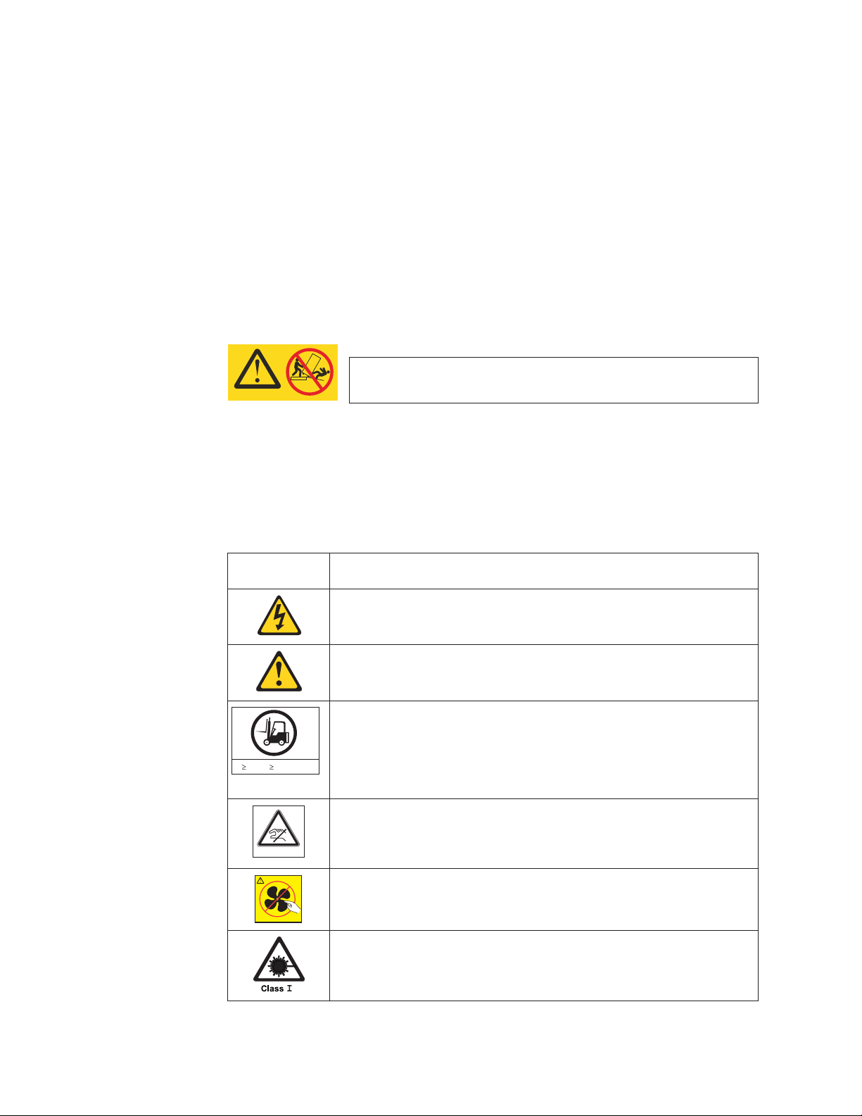
If the symbol
is... It means....
A hazardous electrical condition with less severity than electrical danger.
A generally hazardous condition not represented by other safety
symbols.
A specification of product weight that requires safe lifting practices. The
weight range of the product is listed below the graphic, and the wording
of the caution varies, depending on the weight of the device.
55 kg ( 121.2 lbs)
svc00169
>55kg (121.2 lb)
A potential hazard of pinching the hand or other body parts between
parts.
P/N 18P5850-B
SJ000752
A hazardous condition due to moving parts nearby.
A hazardous condition due to the use of a laser in the product. Laser
symbols are always accompanied by the classification of the laser as
defined by the U.S. Department of Health and Human Services (for
example, Class I, Class II, and so forth).
xvi SAN384B Installation, Service, and User Guide
Page 19
Read and comply with the following caution notices before installing or servicing
this device.
CAUTION:
Energy hazard present. Shorting may result in system outage and
possible physical injury. Remove all metallic jewelry before servicing.
(C001)
CAUTION:
The weight of this part or unit is more than 55 kg (121.2 lb). It takes
specially trained persons, a lifting device, or both to safely lift this
55 kg ( 121.2 lbs)
>55kg (121.2 lb)
part or unit. (C011)
svc00169
CAUTION:
This product is equipped with a 3-wire (two conductors and ground)
power cable and plug. Use this power cable with a properly grounded
electrical outlet to avoid electrical shock. (C018)
CAUTION:
Servicing of this product or unit is to be performed by trained service
personnel only. (C032)
CAUTION:
For CA residents only: IBM recommends installing this product in a room size
of 62 cubic meters (2190 cubic feet) or larger at 0.4 ACH ventilation rate to
reduce the concentrations of any chemicals emitted by the product.
Safety labels
As an added precaution, safety labels are often installed directly on products or
product components to warn of potential hazards. These can be either danger or
caution notices, depending upon the level of the hazard.
The actual product safety labels may differ from these sample safety labels:
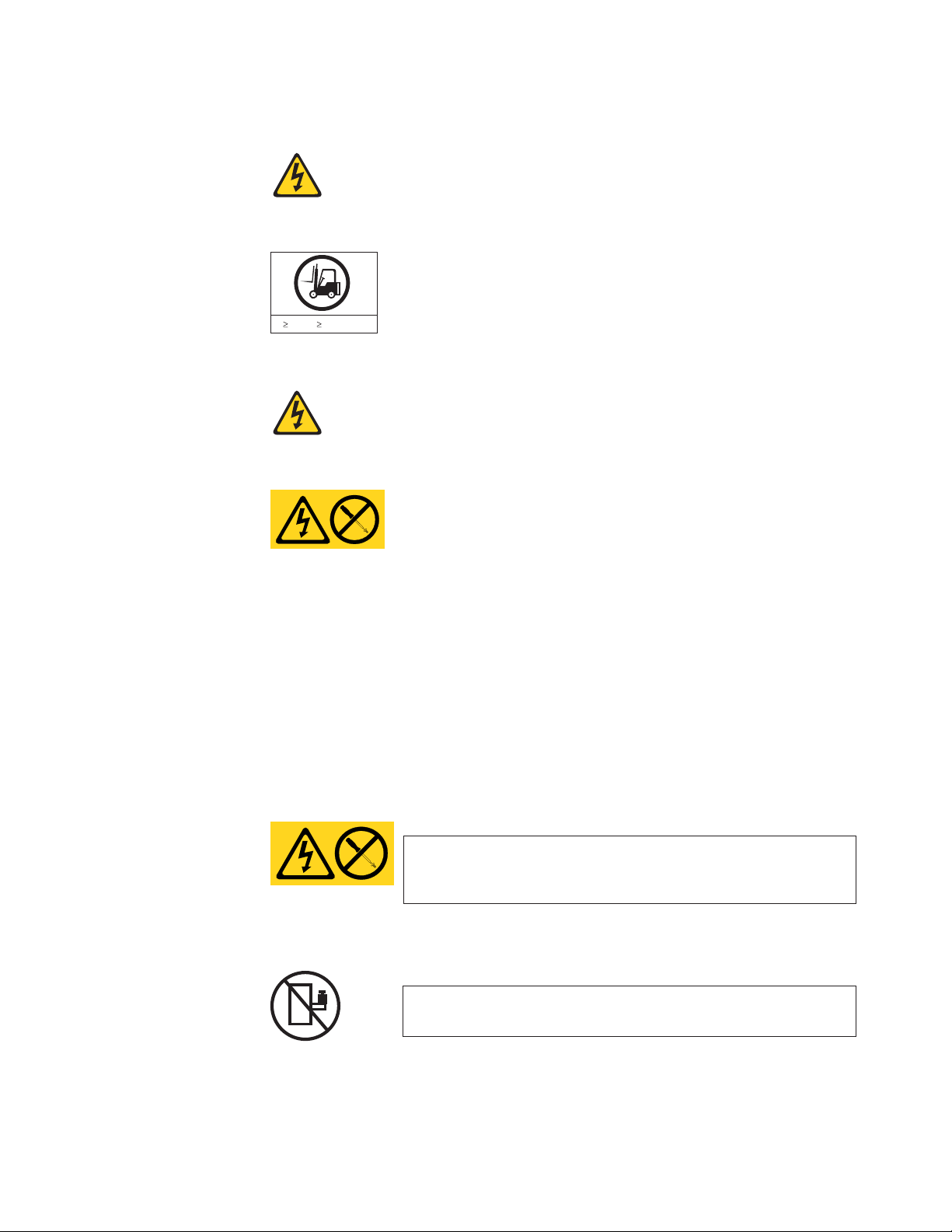
DANGER
Hazardous voltage, current, or energy levels are present inside
any component that has this label attached. Do not open any
cover or barrier that contains this label. (L001)
DANGER
Rack-mounted devices are not to be used as a shelf or work space.
(L002)
Safety notices xvii
Page 20
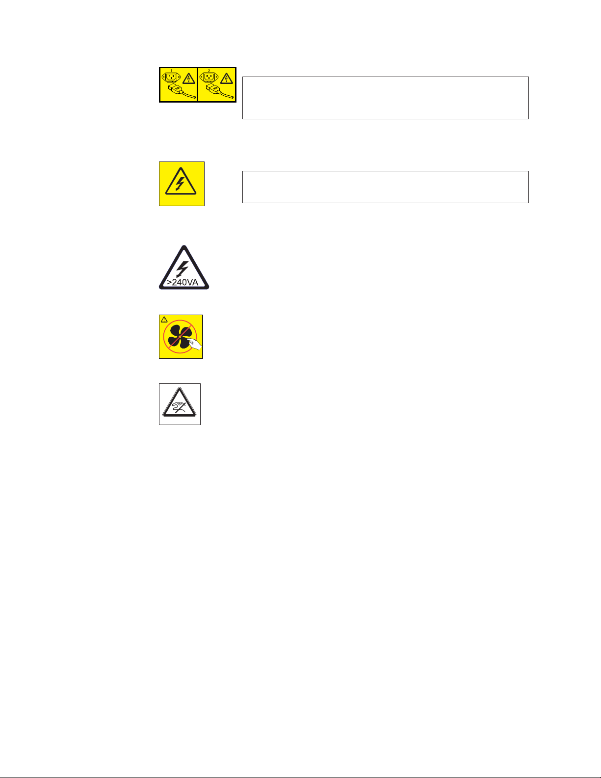
DANGER
Multiple power cords. The product might be equipped with
multiple power cords. To remove all hazardous voltages,
disconnect all power cords. (L003)
DANGER
Hazardous voltage present. Voltages present constitute a shock
hazard, which can cause severe injury or death. (L004)
CAUTION:
Hazardous energy present. Voltages with hazardous energy might
cause heating when shorted with metal, which might result in
splattered metal, burns, or both. (L005)
CAUTION:
Hazardous moving parts nearby (L008)
P/N 18P5850-B
SJ000752
Attention notices
An attention notice indicates the possibility of damage to a program, device, or
system, or to data. An exclamation point symbol may accompany an attention
notice, but is not required. A sample attention notice follows:
Attention: Do not bend a fibre cable to a radius less than 5 cm (2 in.); you can
damage the cable. Tie wraps are not recommended for optical cables because they
can be easily overtightened, causing damage to the cable.
ESD precautions
Attention: Many of the field replaceable units (FRUs) are sensitive to electrostatic
discharge (ESD), and can potentially be damaged by improper handling. Wear a
wrist grounding strap connected to chassis ground (if the SAN384B is plugged in)
or a bench ground. Store all ESD-sensitive components in antistatic packaging.
CAUTION:
Pinch hazard. (L012)
xviii SAN384B Installation, Service, and User Guide
Page 21

Rack safety
Rack installation
DANGER
Observe the following precautions when working on or around your IT rack system:
v Heavy equipment—personal injury or equipment damage might result if
mishandled.
v Always lower the leveling pads on the rack cabinet.
v Always install stabilizer brackets on the rack cabinet.
v To avoid hazardous conditions due to uneven mechanical loading, always install the
heaviest devices in the bottom of the rack cabinet. Always install servers and
optional devices starting from the bottom of the rack cabinet.
v Rack-mounted devices are not to be used as shelves or work spaces. Do not place
objects on top of rack-mounted devices.
v Each rack cabinet might have more than one power cord. Be sure to disconnect all
power cords in the rack cabinet when directed to disconnect power during servicing.
v Connect all devices installed in a rack cabinet to power devices installed in the
same rack cabinet. Do not plug a power cord from a device installed in one rack
cabinet into a power device installed in a different rack cabinet.
v An electrical outlet that is not correctly wired could place hazardous voltage on the
metal parts of the system or the devices that attach to the system. It is the
responsibility of the customer to ensure that the outlet is correctly wired and
grounded to prevent an electrical shock.
(R001 part 1 of 2)
CAUTION:
v Do not install a unit in a rack where the internal rack ambient temperatures will
exceed the manufacturer’s recommended ambient temperature for all your
rack-mounted devices.
v Do not install a unit in a rack where the air flow is compromised. Ensure that air flow
is not blocked or reduced on any side, front, or back of a unit used for air flow
through the unit.
v Consideration should be given to the connection of the equipment to the supply circuit
so that overloading of the circuits does not compromise the supply wiring or
overcurrent protection. To provide the correct power connection to a rack, refer to the
rating labels located on the equipment in the rack to determine the total power
requirement of the supply circuit.
v (For sliding drawers) Do not pull out or install any drawer or feature if the rack stabilizer
brackets are not attached to the rack. Do not pull out more than one drawer at a time.
The rack might become unstable if you pull out more than one drawer at a time.
v (For fixed drawers) This drawer is a fixed drawer and must not be moved for servicing
unless specified by the manufacturer. Attempting to move the drawer partially or
completely out of the rack might cause the rack to become unstable or cause the
drawer to fall out of the rack.
(R001 part 2 of 2)
Safety notices xix
Page 22

Rack relocation (19" rack)
CAUTION:
Removing components from the upper positions in the rack cabinet improves
rack stability during relocation. Follow these general guidelines whenever you
relocate a populated rack cabinet within a room or building:
v Reduce the weight of the rack cabinet by removing equipment starting at the
top of the rack cabinet. When possible, restore the rack cabinet to the
configuration of the rack cabinet as you received it. If this configuration is not
known, you must do the following:
– Remove all devices in the 32U position and above.
– Ensure that the heaviest devices are installed in the bottom of the rack
cabinet.
– Ensure that there are no empty U-levels between devices installed in the
rack cabinet below the 32U level.
– If the rack cabinet you are relocating is part of a suite of rack cabinets,
detach the rack cabinet from the suite.
– Inspect the route that you plan to take when moving the rack to eliminate
potential hazards.
– Verify that the route that you choose can support the weight of the loaded
rack cabinet. Refer to the documentation that came with your rack cabinet
for the weight of a loaded rack cabinet.
– Verify that all door openings are at least 760 x 2030 mm (30 x 80 in.).
– Ensure that all devices, shelves, drawers, doors, and cables are secure.
– Ensure that the four leveling pads are raised to their highest position.
– Ensure that there is no stabilizer bracket installed on the rack cabinet
during movement.
– Do not use a ramp inclined at more than 10 degrees.
– Once the rack cabinet is in the new location, do the following:
- Lower the four leveling pads.
- Install stabilizer brackets on the rack cabinet.
- If you removed any devices from the rack cabinet, repopulate the rack
cabinet from the lowest position to the highest position.
– If a long distance relocation is required, restore the rack cabinet to the
configuration of the rack cabinet as you received it. Pack the rack cabinet in
the original packaging material, or equivalent. Also, lower the leveling
pads to raise the casters off of the pallet and bolt the rack cabinet to the
pallet.
(R002)
xx SAN384B Installation, Service, and User Guide
Page 23
Safety inspections
Perform the following safety checks to identify unsafe conditions. Be cautious of
potential safety hazards that are not covered in the safety checks. If unsafe
conditions are present, determine how serious the hazards are and whether you
should continue before you correct the problem.
Removing AC power
Perform the following steps to remove the alternating current (ac) power:
1. Perform a controlled system shutdown.
2. Set the power switch on the product to the off position.
3. Disconnect the power cables from the power source.
External machine checks
Perform the following external machine checks:
1. Verify that all external covers are present and are not damaged.
2. Ensure that all latches and hinges are in correct operating condition.
3. Check the power cable for damage.
4. Check the external signal cable for damage.
5. Check the cover for sharp edges, damage, or alterations that expose the internal
6. Check that any unused serial ports are covered for dust and ESD protection.
7. Correct any problems that you find.
DANGER
Multiple power cords. (L003)
parts of the device.
The cover should be kept on the serial port whenever it is not being used.
Internal machine checks
Perform the following internal machine checks:
1. Check for any non-IBM changes that might have been made to the machine. If
any are present, obtain the “Non-IBM Alteration Attachment Survey” form,
number R009, from the IBM branch office. Complete the form and return it to
the branch office.
2. Check the condition of the inside of the machine for:
v Metal or other contaminants
v Indications of water or other fluid
v Fire or smoke damage
3. Check for any obvious mechanical problems, such as loose components.
4. Check any exposed cables and connectors for wear, cracks, or pinching.
Safety notices xxi
Page 24

Product recycling and disposal
Refer to the IBM Systems Environmental Notices and User Guide (Z125-5823) on the
product documentation CD for translated environmental statements and
information regarding product recycling and disposal. This document may be
provided either in printed version or on the product documentation CD. See
“Removing the battery” on page 105 for battery removal instructions, if needed to
meet environmental regulations.
xxii SAN384B Installation, Service, and User Guide
Page 25

About this document
This document describes how to install and service the IBM System Storage
SAN384B fabric backbone product. Throughout this document, the product is
|
|
|
|
referred to as the SAN384B. This document includes information specific to the
SAN384B running Fabric OS version 6.4.0. and later. For information about a Fabric
OS version other than 6.4.0, refer to the documentation specific to your Fabric OS
version.
The sections that follow provide information about:
v “Who should read this document”
v “Product documents”
v “Brocade documents”
v “Accessibility features for SAN384B” on page xxiv
Who should read this document
This document is intended for trained service representatives who are responsible
for installing and servicing the SAN384B, and for network administrators
responsible for maintaining and using the SAN384B.
Product documents
The following documents contain information related to this product. The
documentation may be printed material or may be on the documentation CD that
is shipped with the product.
v IBM System Storage SAN384B Installation, Service, and User Guide, GC52-1333 (this
document, which is also available in accessible HTML format on the
documentation CD)
v IBM Systems Safety Notices, G229–9054
v IBM Systems Environmental Notices and User Guide, Z125-5823
v IBM Warranty
|
|
v Implementing an IBM/Brocade SAN with 8 Gbps Directors and Switches, (an IBM
Redbook), SG24-6116
™
Brocade documents
IBM switches use software licensed from Brocade Communications Systems, Inc.
You can find information related to the software that supports the SAN384B in the
following documents on the CD-ROM supplied with this product:
Brocade Fabric OS
v Fabric OS Administrator's Guide
v Fabric OS Command Reference Manual
v Fabric OS MIB Reference
v Fabric OS Message Reference
v Fabric OS Troubleshooting and Diagnostics Guide
v Fabric OS FCIP Administrator's Guide
v FICON Administrator's Guide
© Copyright IBM Corp. 2009, 2010 xxiii
Page 26

v SAN Glossary
Brocade Fabric OS optional features
v Fabric Watch Administrator's Guide
v Web Tools Administrator's Guide
|
|
Brocade HBA publication
v Brocade Adapters Administrator’s Guide
IBM and Brocade product matrix
When you use any of the Brocade documents, you will notice that the model
numbers reflect the original Brocade products. Table 1 provides a product matrix
for you to use to correlate the Brocade products and models to the IBM product
names and machine types and model numbers. Products withdrawn from
marketing are not listed.
Table 1. Brocade and IBM product and model number matrix
IBM machine type and
Brocade product name IBM product name
Brocade DCX-4S SAN384B 2499 Model 192
Brocade DCX SAN768B 2499 Model 384
Brocade 48000 SAN256B Director 2109 Model M48
Brocade 8000 IBM Converged Switch B32 3758 Models B32 and L32
Brocade 7800 SAN06B-R 2498 Model R06
Brocade 7500E SAN04B–R 2005 Model R04
Brocade 5300 SAN80B-4 2498 Model B80
Brocade 5100 SAN40B-4 2498 Models B40 and 40E
Brocade 300 SAN24B-4 2498 Models B24 and 24E
model number
Accessibility features for SAN384B
Accessibility features help users who have a disability, such as restricted mobility
or limited vision, to use information technology products successfully.
Accessibility features
Use and operation of this device is accomplished primarily through external
devices which may provide different accessibility features.
The following list includes the major accessibility features in the SAN384B either
directly or through external devices or interfaces:
v Keyboard-only operation
v Interfaces that are commonly used by screen readers
v Keys that are discernible by touch but do not activate just by touching them
v Industry-standard devices for ports and connectors
v The attachment of alternative input and output devices
Keyboard navigation
This product uses standard Microsoft®Windows®navigation keys.
xxiv SAN384B Installation, Service, and User Guide
Page 27

Vendor software
The SAN384B includes certain vendor software that is not covered under the IBM
license agreement. IBM makes no representation about the accessibility features of
these products. Contact the vendor for the accessibility information about its
products.
Related accessibility information
You can view the publications for the SAN384B in Adobe Portable Document
Format (PDF) using the Adobe Acrobat Reader. The PDFs are provided on a CD
that is packaged with the product. An accessible HTML version of this document is
also included on the documentation CD for this product.
IBM and accessibility
See the IBM Human Ability and Accessibility Center for more information about
the commitment that IBM has to accessibility: www.ibm.com/able.
About this document xxv
Page 28

xxvi SAN384B Installation, Service, and User Guide
Page 29

Chapter 1. Introduction
This chapter introduces the features and components of the IBM System Storage
SAN384B fabric backbone. Throughout this document, the product is referred to as
the SAN384B, or more generically as system, device,orchassis, where appropriate.
This chapter contains the following information:
v “Overview of the SAN384B”
v “Hardware components” on page 2
v “High availability” on page 7
v “Reliability” on page 7
v “Serviceability” on page 7
v “Software features” on page 8
Overview of the SAN384B
The SAN384B is part of IBM's industry-leading backbone-class product line, a
highly robust class of network switching platform that combines breakthrough
performance, scalability, and energy efficiency with long-term investment.
Supporting open systems and System z
the data growth and application demands of evolving enterprise data centers,
achieve server, SAN, and data center consolidation, and reduce infrastructure and
administrative costs.
®
, SAN backbones are designed to address
Key features of the SAN384B include:
|
|
v A horizontal chassis with up to 256 ports through four port blades (in addition
to two core switching and two core processing blades).
v Support for all of the application, port blade, and control processor (CP) blades
supported in the SAN768B, providing flexible system configurations and fewer
types of new blades. (SAN768B CR8 core switch blades are not supported in the
SAN384B chassis.)
v Up to 768 ports can connect with the use of inter-chassis links (ICLs).
v Support for high-performance port blades running at 1-, 2-, 4-, 8-, or 10-Gbps,
enabling flexible system configuration.
v Supports 1-, 2-, 4-, and 8-Gbps auto-sensing Fibre Channel ports. Trunking
technology groups up to eight ports to create high performance 64-Gbps ISL
trunks between switches. (10 Gbps ports (FC10-6) are 10 Gbps only.)
v Dual-redundant control processor blades (CP8) and core switch blades (CR4S-8)
provide high availability and enable nondisruptive software upgrades.
v Redundant and hot-swappable CP8 and CR4S-8 blades, power supplies, blower
assemblies, and WWN cards enable a high availability platform for mission
critical SAN applications.
v Universal ports that self-configure as E_ports, F_ports, FL_ports, Ex_ports, and
M_ports (mirror ports). 10 Gbps ports (FC10-6) are E-Ports only.
v Fibre Channel over IP (FCIP) functionality through the FX8-24 blade.
v Fibre Channel over Ethernet (FCoE) capability through the FCOE10-24 blade.
© Copyright IBM Corp. 2009, 2010 1
Page 30

Hardware components
The SAN384B features a modular and scalable mechanical construction that allows
a wide range of flexibility in installation, fabric design, and maintenance. The
chassis may be mounted with the cables facing the front of the equipment rack or
to the rear, and consists of the following:
v Up to four hot-swappable port blade assemblies can be configured in a single
|
|
|
|
|
|
|
|
|
chassis, delivering up to 256 Fibre Channel ports
v Two slots for control processor blades (CP8):
– A single active CP8 blade can control all 256 ports in the chassis
– The standby CP8 blade assumes control of the SAN384B if the active CP fails
v Two slots for core switch blades (CR4S-8):
– CR4S-8 blade interconnects all port blades
– Two inter-chassis link (ICL) connectors per blade to connect to another chassis
– Both CR4S-8 blades are active
v Modular hot-swappable port blades:
– 16-port, 8-Gbps blades (FC8-16)
– 32-port, 8-Gbps blades (FC8-32)
– 48-port, 8-Gbps blades (FC8-48)
– 64-port 8-Gbps blades (FC8-64)
– 6-port, 10-Gbps blades (FC10-6)
v Modular hot-swappable application blades:
– FR4-18i: 18-port (16 FC + 2 GbE), up to 4 blades per chassis, supporting Fibre
– FX8-24: 24-port (12 FC, 10 GbE, 2 10GbE) FCIP extension blade enabling long
– FCOE10-24: 24-port (24 10GbE) CEE-based FCoE blade enabling enhanced
v Modular hot-swappable field replaceable units (FRUs):
– Two blower assemblies
– Two 100 to 240 VAC power supplies. 240 VAC is recommended for efficiency
– Two WWN cards
– Small Form-factor Pluggable (SFP, SFP+, and mSFP) optical transceivers. SFP
– Extended Form-factor Pluggable (XFP) optical transceivers (10-Gbps)
– 1 GbE copper SFP transceivers for the IP ports on the routing blade
Channel Routing Services and FCIP
distance communication over existing IP infrastructure
connectivity using existing Ethernet infrastructure. This blade cannot be used
in the same chassis as the high density port blade FC8-64 or the FX8-24 or
FR4-18i application blades.
and high availability.
transceivers support speeds of 1, 2, and 4 Gbps. SFP+ and mSFP transceivers
support speeds of 2, 4, and 8 Gbps.
|
|
Note: The 8-Gbps SFPs and mSFPs auto-negotiate at 2, 4, and 8 Gbps. The
4-Gbps SFPs auto-negotiate at 1, 2, and 4 Gbps.
v Port-side exhaust kit (standard), which directs the exhaust airflow to the cabinet
service aisle
v All blades are serviced from the port side of the SAN384B. Blowers, power
supplies, and power cables are serviced from the nonport side
v World Wide Name (WWN) cards on the nonport side, with WWN status LEDs
located under the bezel
2 SAN384B Installation, Service, and User Guide
Page 31

v Improved cable management using two vertical cable management finger
assemblies
v Constant intake and FRU temperature monitoring
v Redundant AC primary power connections to ensure high availability. Each
power supply has its own connector
Note: Airflow in the SAN384B is from the non-port (non-cable) side to the left side
of the chassis. With the port-side exhaust kit installed (see Figure 2 on page
4, the air flows out the vent on the port side of the chassis.
Figure 1 shows a sample configuration of the port side of the SAN384B with four
FC8-48 port blades installed.
1
2
4
Figure 1. Port side of the SAN384B (sample configuration)
1 FC8-48 port blade (example, 4x) 3 Control processor blade (CP8) (2x)
2 Core switch blade (CR4S-8) (2x) 4 Exhaust vent
Figure 2 on page 4 shows the SAN384B with the port-side exhaust kit installed
over the chassis exhaust vent (sample configuration). The exhaust is routed from
the chassis exhaust vent through the port-side exhaust kit. The exhaust exits
through the vent grill below the chassis.
3
384b001
Chapter 1. Introduction 3
Page 32

384b002
Figure 2. Port side of the SAN384B with the exhaust kit installed (sample configuration)
Figure 3 shows the non-port side of the SAN384B.
1
2
3
Figure 3. Blower (non-port) side of the SAN384B
1 WWN bezel 3 Blower assembly (2x)
2 Power supply (2x)
4 SAN384B Installation, Service, and User Guide
384b003
Page 33

SAN384B blades
|
|
|
|
|
|
|
|
Table 2 summarizes the port, application, control processor, and core switch blades
that are available for the SAN384B.
Table 2. Blades available for the SAN384B
Description Feature Code Name Function
Control processor
blade
Core switch blade N/A CR4S-8 The CR4S-8 blade
16-port 8-Gbps port
blade
32-port 8-Gbps port
blade
48-port 8-Gbps port
blade
N/A CP8 The CP8 blade
contains the control
plane for the chassis.
There are two CP8
blades for
redundancy. This
control processor
blade is compatible
with the SAN768B
and SAN384B.
contains the ASICs
for switching
between port blades.
Every port blade
connects to each core
switch blade. There
can be up to 256 total
ports for port blades.
Each core switch
blade connects to 128
backplane ports. Core
switch blades have
additional front port
connectivity to
connect multiple
chassis and
backplane
connections for the
storage server blade.
This core switch
blade is compatible
only with the
SAN384B.
FC3816 FC8-16 A 16-port blade
supporting 1–, 2–, 4–,
and 8–Gbps port
speeds.
FC3832 FC8-32 A 32-port blade
supporting 1-, 2-, 4-,
and 8-Gbps port
speeds.
FC3848 FC8-48 A 48-port blade
supporting 1-, 2-, 4-,
and 8-Gbps port
speeds.
Chapter 1. Introduction 5
Page 34

Table 2. Blades available for the SAN384B (continued)
Description Feature Code Name Function
|||
|
|
|
|
|
|
|
|
|
|
|
|
|
64-port 8-Gbps port
blade
6-port 10-Gbps port
blade
Fibre Channel router
blade
FCIP extension blade FC3890 FX8-24 The FX8-24 blade
Fibre Channel over
Ethernet blade
FC3864 FC8-64 A 64-port port blade
supporting 2, 4, and
8 Gbps port speeds.
This blade cannot be
used in the same
chassis with an
FCOE10-24 blade.
FC3870 FC10-6 A 6-port blade
supporting 10-Gbps
port speed. Blade
provides 10-Gbps
ISLs.
FC3850 FR4-18i The FR4-18i blade
has 16 4-Gbps
physical Fibre
Channel SFP ports
supporting Fibre
Channel Routing
Services and two
physical Gigabit
Ethernet (GbE) SFP
ports supporting
Fibre Channel Over
IP (FCIP). The two
physical GbE ports
can support up to 16
virtual E_ports.
enables FCIP
functionality over
existing IP
infrastructure. It has
twelve FC ports, ten
1 GbE ports, and two
10 GbE ports
available.
FC3880 FCOE10-24 The FCOE10-24 blade
enables FCoE
functionality over
existing Ethernet
infrastructure
utilizing CEE
protocols. It has
twenty-four 10 GbE
ports available. This
blade cannot be used
in the same chassis
with an FC8-64 high
density port blade or
the FR4-18i or FX8-24
application blades.
6 SAN384B Installation, Service, and User Guide
Page 35

High availability
The following features contribute to the SAN384B's high-availability design:
v Redundant, hot-swappable blades and FRUs
v Enhanced data integrity on all data paths
v Fabric Shortest Path First (FSPF) rerouting around failed links
v Integration with Simple Network Management Protocol (SNMP) managers
v Automatic control processor failover
v Nondisruptive "hot" software code loads and activation
v Easy configuration, save, and restore
v Hot-swappable World Wide Name (WWN) cards
The high-availability software architecture of the SAN384B provides a common
framework for all applications that reside on the system, allowing global and local
status to be maintained through any component failure. High-availability elements
consist of the High Availability Manager, the heartbeat, the fault/health
framework, the replicated database, initialization, and software upgrade.
The High Availability Manager controls access to the standby control processor,
facilitates software upgrades, prevents extraneous switchover activity, closes and
flushes streams, provides flow control and message buffering, and supports a
centralized active and standby state.
Reliability
|
|
|
Serviceability
|
|
The SAN384B uses the following error detection and correction mechanisms to
ensure reliability of data:
v Error Detection and Fault Isolation (EDFI) mechanism, which checks for encoder
errors and fault isolation, such as cyclic redundancy checking (CRC), parity
checking, checksum, and illegal address checking.
v Power-on self test (POST)
v Dual control processors that enable hot, nondisruptive fast firmware upgrades
v Each control processor contains one serial port and two Ethernet ports, for
management and for service. Offline control processor diagnostics and remote
diagnostics simplify troubleshooting. The standby control processor monitors
diagnostics to ensure it is operational, should a failover be necessary
v Bus monitoring and control of blades and other field-replaceable units (FRUs).
The SAN384B provides the following features to enhance and ensure serviceability:
v Modular design with hot-swappable components
v Flash memory that stores two firmware images per control processor
v USB port on control processor blades for all tasks that formerly required an
FTP/SCP server, including software and firmware upgrades
v Nonvolatile random-access memory (NVRAM), containing the OEM serial
number, IBM serial number, revision information, and part number information
v Background health-check daemon
v Memory scrubber, self test, and bus ping to determine if a bus is not functioning
v RASlog messages
Chapter 1. Introduction 7
Page 36

v SMI-S compliant
v Watchdog timers
v Status LEDs
v Predictive diagnostics analysis through Fabric Watch
v SNMP (including version 3) integration with higher-layer managers
v Vertical cable management finger assemblies to accommodate the horizontal
Software features
The Fabric OS allows any Fibre Channel-compliant device to attach to the switches
as long as it conforms to the device login, name service, and related Fibre Channel
standards. Each operating environment requires that a Fibre Channel host bus
adapter (HBA) be available with a standards-compliant driver for correct interface
to the fabric.
orientation of the blades
Fabric OS consists of a set of embedded applications running on top of an
embedded Linux
v Name server
v Alias server
v Zone server
v Simple Network Management Protocol (SNMP) agent
v SMI-S compliant API
v Syslog auditing
v RCS (Reliable Commit Service)
v NTP
v Tasks to manage address assignment, routing, link initialization, fabric
v Integrated Routing (optional feature)–This feature allows any port in a SAN384B,
v FICON
Security
Table 3 highlights some of the key security features available for the SAN384B and
for other switches running Fabric OS 5.2.0 or later.
®
operating system kernel. These applications include:
initialization, link shutdown, SAN384B shutdown, and the user interface.
SAN80B-4, and SAN40B-4 to be configured as an EX_port supporting Fibre
Channel (FC) routing. This eliminates the need to add a routing blade or use of
the SAN18B-R for FC routing (FCR) purposes, and this also provides double the
bandwidth for each FC router connection when connected to another 8
Gbps-capable port.
®
Accelerator (optional feature), which is designed to support secure
high-speed data movement between multiple locations
Table 3. Security features
Security features Description
DH-CHAP Login banner
SSHv2 (using AES, 3DES, RSA) Monitoring of attempted security breaches
HTTPS (using AES) Monitoring of attempted security breaches
SNPMv3 Fibre Channel security policies: DCC and
8 SAN384B Installation, Service, and User Guide
(through audit logging)
(through Fabric Watch Security Class)
SCC
Page 37

Table 3. Security features (continued)
Security features Description
FC-SP Trusted Switch (FCS) for central security
management
Secure RPC Management access controls (SNMPv3,
Telnet, FTP, serial port, front panel)
Secure file copy (SCP) Hardware-enforced zoning by WWN and/or
domain/port ID
Telnet disable Default zoning
Telnet timeout RSCN suppression and aggregation
IP filters (block listeners) Configurable RSCN suppression by port
Secure passwords (centralized control via
RADIUS/CHAP)
Up to 255 multiple user accounts (MUAs). Event auditing
Role-based access controls (RBACs) Change tracking
Administrative domains/Virtual fabrics Firmware change alerts in Fabric Manager
Boot PROM password reset Persistent port disable
Password hardening policies Persistent domain ID
Upfront login in Web Tools E_port disable
NTPv3 (to synchronize timestamps)
Network Manageability
The SAN384B has a single domain and is managed as a single element with the
Data Center Fabric Manager or Web Tools. The SAN384B responds to its own IP
address and appears as a separate entity to the Telnet protocol and SNMP.
All management interfaces, such as Telnet, Web Tools, standards compliant SMI-S,
and Management Server, support a "port N within blade M" naming scheme.
The SAN384B supports SNMPv1 and SNPMv3. When SNMP devices send SNMP
messages to a management console running SAN management software, the
information is stored in a management information base (MIB). Fabric OS v6.2 and
later supports the latest Fibre Alliance Fibre Channel Management (FCMGMT) and
Storage Management Initiative (SMI) MIBs, which allow common information
necessary for management software to provide information to a SAN
administrator.
Note: Refer to the Fabric OS MIB Reference for additional MIB information.
Chapter 1. Introduction 9
Page 38

10 SAN384B Installation, Service, and User Guide
Page 39
Chapter 2. Installing a SAN384B in a cabinet
The SAN384B is only available for installation in the IBM TotalStorage®2109 SAN
Switch Cabinet C36. This product is to be installed and serviced only by qualified
IBM service representatives. The SAN384B can be ordered pre-installed in the
cabinet, or it can be added to an existing C36 cabinet. The cabinet is designed to
support a total of three SAN384Bs. Each installation of the SAN384B requires the
port-side exhaust vent kit, which directs the exhaust to the service aisle and also
serves as the rack installation kit. If three SAN384B products are ordered, two will
be pre-installed in the C36 cabinet, and the third will be installed in the cabinet at
the customer site.
This chapter describes how to install a SAN384B into a C36 cabinet, and how to
remove the SAN384B from the cabinet in the event you need to move or replace
the SAN384B. If all SAN384B units are already installed in the cabinet, continue on
to Chapter 3, “Starting and configuring the SAN384B,” on page 33. The installation
requires a minimum of two people for a safe installation.
Attention: Refer to “Safety notices” on page xiii for general safety instructions
“Safety notices and labels” on page xiii, and “Rack safety” on page xix before
performing any installation or service procedures.
CAUTION:
The weight of this part or unit is more than 55 kg (121.2 lb). It
takes specially trained persons with a lifting device to safely lift
this part or unit. (C011)
55 kg ( 121.2 lbs)
svc00169
CAUTION:
A fully populated SAN384B weighs approximately 68 kg (150 lb). Before you
install it, verify that the additional weight of the chassis does not exceed the
cabinet's weight limit or unbalance the cabinet. When you calculate the
additional weight, include the weights of all components that can potentially be
added, to avoid overloading in the future.
CAUTION:
For CA residents only: IBM recommends installing this product in a room size
of 62 cubic meters (2190 cubic feet) or larger at 0.4 ACH ventilation rate to
reduce the concentrations of any chemicals emitted by the product.
Ordering the lift tool
Important
The lift tool is required only when you install an additional SAN384B or
when you install or remove the SAN384B from the cabinet. Ensure that the
lift tool will be available on location at the time of the installation.
The ordering procedures for the lift tool vary depending on your location. You
should direct questions about these procedures to your regional representative.
© Copyright IBM Corp. 2009, 2010 11
Page 40

World trade locations
The following ordering procedures are for world trade locations:
v Order the lift tool by using the parts order system, like any other part.
v Use the following part numbers when you order:
– Lift tool: PN 09P2481
– 24–inch load plate: PN 11P4369
v You do not record parts usage.
v Return the lift tool and the 24–inch load plate to the parts center after you
complete the installation or removal of the SAN384B.
United States locations
In the United States, call UPS Logistics at 800–528–6070 to order the lift tool and
the 24–inch load plate.
Note: For the SSR branch and territory, the United States cannot order the lift tool
or 24–inch load plate through the parts order system. UPS Logistics are used
to ship and return the lift tool and 24–inch load plate.
Use the following part numbers when you order:
v Lift tool: PN 09P2481
v 24–inch load plate: PN 11P4369
Attention: When you order the lift tool, you will receive an 18–inch load plate.
Do not use the 18–inch load plate. You must order and use a 24–inch load plate
when you install the SAN384B to be able to safely install this product. The 24-inch
load plate includes a platform with a middle section that can slide out to extend
across the gap between the lift tool and the mounting position inside the C36
cabinet.
You must provide the following information when you order the lift tool. This
information is necessary to ensure that the lift tool is delivered when you need it.
Failure to provide this information might delay the completion of the order request
and the shipping request. It might also result in a time and date to return the tool
that is different from what you need.
v Phone number and customer contact
v Account code: 98577
v Time and date of delivery
v Accurate destination address with zip code
v Time and date of return pickup
You must return the lift tool at the time that was scheduled with UPS Logistics. If
you need to change the scheduled return time or date, contact UPS Logistics.
You are responsible for ensuring that all of the paperwork and components are
packed and restored in the arbocrate (shipping container) of the lift tool. Ensure
that the lift tool is functioning properly before you release the tool to UPS Logistics
for return. You are accountable for the lift tool until UPS Logistics picks up the lift
tool for return delivery to their parts storage facility.
Contact your branch office tools coordinator or your region specialist if you have
any questions or concerns.
12 SAN384B Installation, Service, and User Guide
Page 41

Installation guidelines
Follow these general installation guidelines:
1. Provide a space that is 9 rack units (9U) high, 61.19 cm (24.09 in.) deep, and
43.74 cm (17.22 in.) wide. 1U is equal to 4.45 cm (1.75 in.).
2. Ensure that dedicated electrical branch circuits with the following requirements
are met:
v 200 – 240 VAC, 50–60 Hz (two branch circuits)
v Two cables for the 200 - 240 VAC service
v Power supply standards (“Power specifications”) are met
v Protected by a circuit breaker in accordance with local electrical codes
v Supply circuit, line fusing, and wire size adequate to the electrical rating on
the chassis nameplate
v Location close to the chassis and easily accessible
v Grounded outlets installed by a licensed electrician and compatible with the
power cords
Attention: To maximize fault tolerance, connect each power cord to a
separate power source.
3. To ensure adequate cooling, plan to install the chassis with the port side facing
the aisle where exhaust air is released (usually called the service aisle). This
prevents the fans from pulling in heated exhaust air.
4. Plan for managing the cables before you install the chassis. A fully populated
SAN384B will have a large number of cables that must be carefully routed to
minimize problems with installation and replacement of components, and in
order to maintain the minimum bend radius required for optical cables. Due to
port density and the potentially large number of cables, if cables are not routed
to the sides, then removal and replacement of blades and other components
may be difficult to accomplish. Refer to “Managing cables” on page 42 for more
specific information. You can manage the cables in a variety of ways, such as:
v Routing the cables through the vertical cable management finger assemblies
installed on either side of the chassis
v Routing the cables out to either side of the chassis
v Routing the cables through the cable channels on the sides of the cabinet
v Using patch panels
5. Ensure that the following are available for configuration:
v Workstation with an installed terminal emulator, such as HyperTerminal
v Serial cable (provided)
v Three Ethernet cables (including one spare)
v Access to an FTP server for backing up the switch configuration or collecting
supportsave output data (optional)
v SFPs and compatible cables
6. Ensure that the air intake vents have a minimum of 2 inches of airspace.
7. Ensure that the air temperature on the air intake side is less than 40°C (104°F )
during operation.
Chapter 2. Installing a SAN384B in a cabinet 13
Page 42

Installing a SAN384B in a 2109 C36 cabinet
This section describes how to install the SAN384B in the Model C36 cabinet. These
procedures use parts that are included in the hardware accessory kit and the
port-side exhaust kit, which also functions as a lower supporting shelf. No
rack-mount rail kit is required for this installation.
To safely complete the installation, a minimum of two people are required.
Time required
Allow approximately 3 hours to complete this entire procedure. This total includes
unpacking, assembling, disassembling, and repacking the lift tool. The time
estimate is for the physical installation of the SAN384B only. It does not include
|
installing Ethernet cables, transceivers, attaching and routing the fiber optic cables,
or completing the initial configuration.
The SAN384B and the lift tool should be delivered to a location near to the final
installation, with clear aisles for maneuvering the lift tool loaded with the chassis.
Since the lift tool can be used to move the chassis the short distance from the
delivery location to the installation, it is recommended that you assemble the lift
tool before starting the installation steps.
Note: Brief assembly instructions for the lift tool are attached to the back of the lift
tool. Additional instructions are included below in “Unpacking and
assembling the lift tool” on page 15.
Table 4 provides a summary of time estimates for the different installation tasks
and the tools required for each task.
Table 4. Installation tasks, time, and items required
Installation task Time estimate Items required
Unpacking and assembling
the lift tool
Site preparation and
unpacking the SAN384B
Installing the port-side
exhaust kit
Mounting and securing the
SAN384B in the rack
Installing power cables and
powering on the SAN384B
Establishing serial
connection, logging on to the
SAN384B, and configuring IP
addresses.
15 minutes No special tools required.
30 minutes #2 Phillips screwdriver (for
cable management comb)
Pallet jack (if the shipment
has not been positioned near
the installation site)
15 minutes Torque wrench with #2
Phillips screwdriver tip
Flathead screwdriver
15 minutes Torque wrench with #2
Phillips screwdriver tip
Lift tool and load plate
20 minutes Power cables
20 minutes Serial cable (provided in the
accessory kit). Workstation
computer with a serial port
or terminal server port and a
terminal emulator
application (such as
HyperTerminal). Ethernet IP
addresses for the switch.
14 SAN384B Installation, Service, and User Guide
Page 43

Table 4. Installation tasks, time, and items required (continued)
Installation task Time estimate Items required
Installing an Ethernet cable,
opening a Telnet session, and
configuring the SAN384 B
domain ID, date and time,
and additional system
parameters. Verifying and
backing up the configuration.
|
|
|
|
|
|
Installing SFP, SFP+, mSFP,
and XFP (10-Gbps) optical
transceivers as needed
Attaching fiber optic cables,
cable wraps, and cable
guides
Disassembling and packing
the lift tool
20 minutes Ethernet cable for Telnet
access. Refer to the Fabric OS
Administrator’s Guide.
15-30 minutes (depending on
port blades installed)
2-3 hours Fiber optic cables and cable
20 minutes No special tools required.
Optical transceivers.
wraps.
Unpacking and assembling the lift tool
Assembling the lift tool before starting the installation will simplify the installation.
The lift tool consists of several parts, including:
v The fully assembled main vertical section of the lift tool with wheels, wheel lock,
cables and winch attached
v Attachable lift forks, which slide onto the front of the lift tool and are secured in
place by spring-loaded pins and ring pins
v 24-inch load plate with sliding middle section (ordered separately to use in place
of the 18-inch solid single-piece load plate)
v Anti-tip bars
v Retention straps
v Wheel chocks
Assembly instructions are attached to the back of the main vertical section of the
lift tool. The following supplemental information may help with the assembly.
1. With one person at either end, lift the main section of the lift tool out of the
shipping crate.
2. Review the assembly instructions attached to the back of the lift tool, if
necessary.
3. With the lift tool still horizontal, insert the two legs with caster wheels into
the holes in the front of the lift tool.
4. Pull up on the spring-loaded leg lock pins, sliding the legs in until the pins
snap into place through the holes in the legs, securing them in place.
5. Tilt the lift tool upright, resting on all four wheels. Set the wheel brake, if
desired, by stepping down on the brake pedal. (Note the brake release on the
left side of the brake pedal.)
6. Attach the two forks to the lift tool, sliding the two holes in each over the
ends of the two bars. If the winch is in the lowest position, you may need to
raise it to provide enough clearance to slide the forks into position. Secure
each lifting fork in place with two ring-pins.
Chapter 2. Installing a SAN384B in a cabinet 15
Page 44
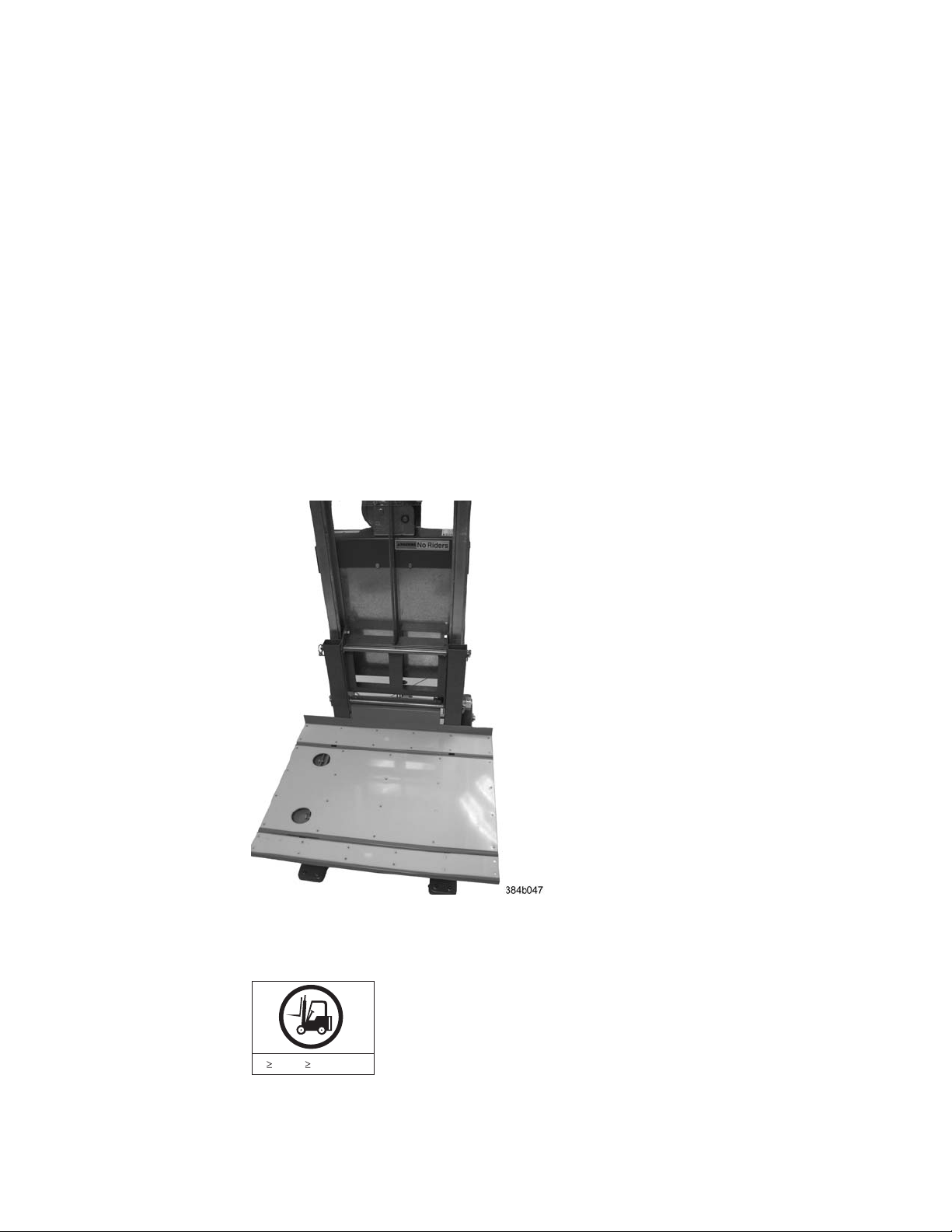
7. Attach the 24-inch load plate, by slipping the top curved portion under the
horizontal bar, and resting the load plate on the forks.
8. Attach the anti-tip bars (recommended to provide additional stability when
the loaded lift tool is raised more than 45 cm (18 in) high). Install these from
the rear of the lift tool, by sliding them inside the horizontal legs, pulling up
on the leg lock pins to allow the pins to engage the holes in the legs and the
anti-tip bars.
9. Secure the anti-tip brackets to the lift tool with the supplied brackets and
bolts.
10. The lift plate has a middle section that can be extended to the right (when
viewed from the back of the lift tool). This middle section is secured in place
by two spring-loaded pins. Familiarize yourself with releasing the pins and
sliding this section. There are two stops: half-way extended and fully
extended. This middle section will need to be fully extended during the
installation to safely span the gap between the lift tool and the cabinet
mounting position.
11. Move the assembled lift tool and retention straps near the equipment to be
installed. Figure 4 shows the assembled lift tool with the 24-inch load plate
installed.
Figure 4. Assembled lift tool with 24-inch load plate
Unpacking the SAN384B
55 kg ( 121.2 lbs)
To unpack the SAN384B, follow these steps:
16 SAN384B Installation, Service, and User Guide
CAUTION:
The weight of this part or unit is more than 55 kg (121.2 lb). It
takes specially trained persons with a lifting device to safely lift
this part or unit. (C011)
svc00169
Page 45

1. If the product needs to be transported a long distance, or if there are uneven
floors to cross, keep the product in its original packaging, and relocate the
entire shipment close to the installation location, using a pallet jack to lift and
move it.
Note: The standard packaging does not incorporate a wood pallet and pallet
brackets. The chassis sits on top of a plastic shipping tray.
2. Once the shipment is in a location close to the installation, cut the bands that
encircle the packaging.
3. Lift the cardboard box off the chassis. Installation kits are packed within this
outer carton, so you may need to open the top of the box to remove the kits
or to press down on them as you lift the outer carton. Save the packing
materials if you are returning an old chassis.
4. Remove the port side exhaust kit, hardware accessory kit, chassis door, cable
management finger assemblies, and foam from the top of the chassis. Remove
the loose foam blocks from the corners of the chassis. Remove the anti-static
plastic from the chassis.
5. Place the kits and other installation pieces near the installation.
6. Move the lift tool next to the plastic shipping tray at the blower and power
supply end of the chassis. Position the lift tool with its left side next to the
shipping tray (see Figure 5).
Figure 5. Lift tool positioned next to the chassis on the shipping tray
7. Using the lift tool winch mechanism, adjust the height of top of the load plate
to slightly below the bottom surface of the chassis.
8. Set the lift tool brake.
9. Carefully slide the chassis across the foam blocking in the shipping tray and
onto the center of the load plate. Do not use any of the handles on the
blowers or power supplies to move the chassis.
Chapter 2. Installing a SAN384B in a cabinet 17
Page 46

10. Attach the lift tool retention straps to secure the chassis to the load plate. This
is particularly important if you will be moving the chassis across any uneven
floor, or will be raising the chassis more than 45 cm (18 inches).
11. For safety considerations during moving, lower the load platform to its lowest
position.
12. Release the lift tool brake, and carefully move the chassis near the cabinet for
installation.
Installing the port-side exhaust kit
Complete the following instructions to install the port-side exhaust kit in a
2109-C36 cabinet before installing the SAN384B chassis.
Exhaust kit parts list
Table 5 lists items illustrated in Figure 6 on page 19.
Table 5. Parts list for port-side exhaust kit for C36 cabinets
Item Description Quantity
A Top rail 1
B Duct 1
C Shelf 1
D 10-32 x .5 in. (1.27 cm)
Phillips screw (blue Loctite
on threads)
E 10-32 x .63 in.(1.60 cm)
Phillips screw with square
cone washer
F 10-32 clip nut for cabinets
that have rails with round
holes
G 10-32 retainer nut for
cabinets that have rails with
square holes
H Alignment washer for
cabinets that have rails with
square holes
I 6-32 x .25 in. (.635 cm)
Phillips screw
12
12
8
8
12
2
18 SAN384B Installation, Service, and User Guide
Page 47

I-1
I-3
I-2
I-4
I-5
I-6
I-7
C
Port Side
(Exhaust)
DEF
10-32 x .5" 10-32 x .63"
10-32 Clip Nut
GH I
10-32 Retainer Nut Alignment Washer
Figure 6. Port-side exhaust kit assembly for 27 to 31 in. (68.58 to 78.74 cm) cabinets
6-32 x .25"
Chapter 2. Installing a SAN384B in a cabinet 19
384b032
Page 48

Torque requirements
Use the following torque settings when tightening screws that secure the port-side
exhaust kit and SAN384B to the equipment cabinet.
Table 6. Torque requirements for mounting screws
Screw size Torque
6-32 x .25 in. (.635 cm) Phillips screw 8.75 in.-lbs (10 cm-kg)
10-32 x .63 in.(1.60 cm) Phillips screw 32 in.-lbs (36.86 cm-kg)
Installing the exhaust kit hardware
1. Remove the rear door (exhaust side) from the C36 cabinet. Set the door aside,
away from the installation.
2. The exhaust side of the port side exhaust kit will be installed facing the rear of
the C36 cabinet, and the port side of the SAN384B chassis will also face this
direction.
3. Install 10 clip nuts (F in Figure 6 on page 19) or retainer nuts (G) in the rear
vertical cabinet rail locations shown in Figure 7 on page 21, and 4 clip nuts or
retainer nuts in the front vertical cabinet rails. Eight clip nuts and retainer nuts
are provided with the exhaust kit, and six are provided with the hardware
accessory kit. Install the lower two nuts at the same relative locations on all
four cabinet vertical rails, to provide a level mounting of the shelf. The fourteen
nuts will secure the eight 10-32 screws that mount the port side exhaust kit
shelf (position 23 in Figure 7 on page 21) and the six that are used to attach the
SAN384B chassis to the cabinet (positions 25, 28, and 30 in Figure 7 on page
21).
Note: For rails with round holes, use clip nuts. For rails with square holes, use
retainer nuts. Figure 7 on page 21 is only an example showing relative
positions for these nuts in the cabinet rails to mount the shelf and
chassis. You can mount the shelf and chassis in9Uofcabinet space
higher or lower in the cabinet than shown.
Note: Screws, clip nuts, and retainer nuts for attaching the SAN384B to the
cabinet are provided in the SAN384B hardware accessory kit.
20 SAN384B Installation, Service, and User Guide
Page 49
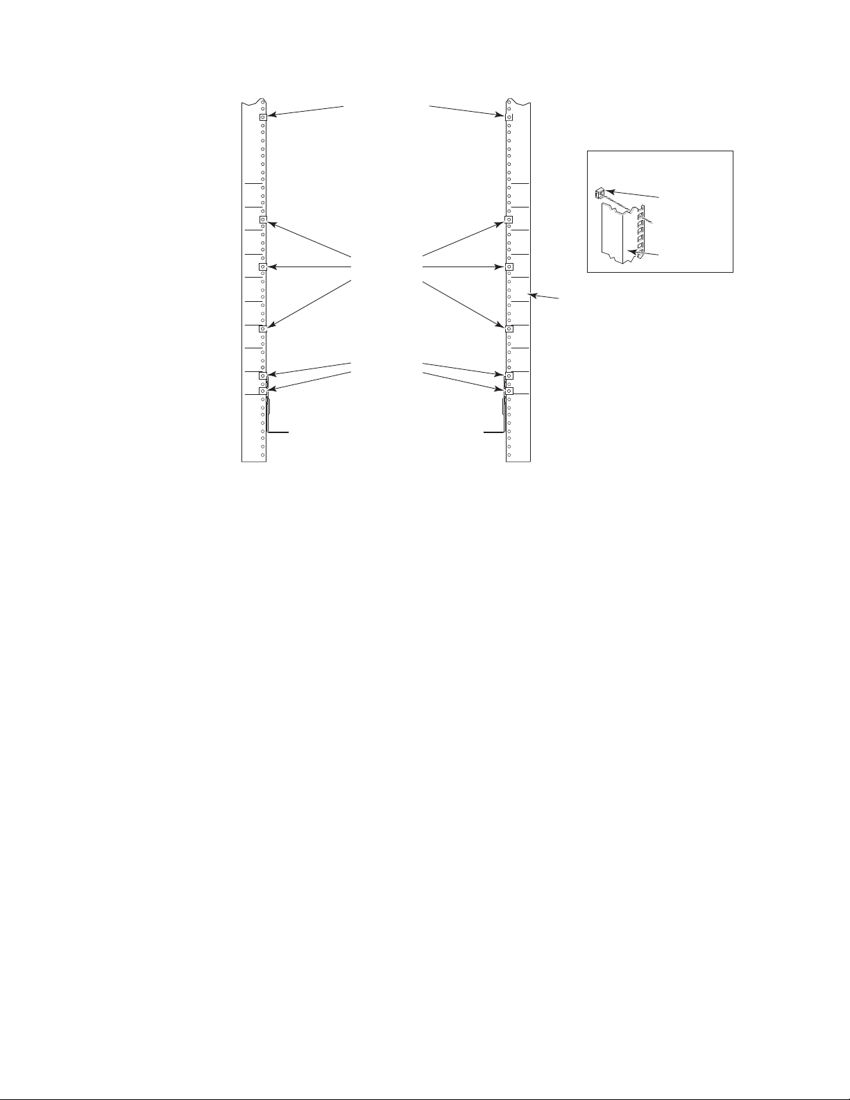
clip nut attachment
for round-hole rails
Setup for Rails
with Square Holes
31
30
29
28
27
26
25
24
23
clip or retainer
nut locations
for chassis
clip or retainer
nut locations
for shelf
31
30
29
28
27
26
25
24
23
rail
384b046
retainer nut
(Item G)
Rail
Figure 7. Clip and retainer nut locations on exhaust side cabinet rails (example showing
relative positions)
4. Install the shelf (C in Figure 6 on page 19), using these steps:
a. The shelf can be adjusted to a length of between 27 and 31 inches (68.58
and 78.74 cm) to match the cabinet size. To lengthen or shorten the shelf,
loosen by approximately 1/2 turn the four 6-32 screws in the four slots on
the shelf (I-4 through I-7 Figure 6 on page 19) and adjust the shelf to the
desired length.
Note: We recommend two people for the installation of the shelf, one at
either end of the cabinet to support and align it correctly while
attaching it to the cabinet.
b. Tilt the shelf at an angle to fit it between the rails, and then position it
horizontally and level with the shelf mounting tabs on the outside of the
cabinet vertical rails, and aligned with the clip nuts you installed earlier.
c. Secure the shelf to the cabinet with eight 10-32 screws with washers (E in
Figure 6 on page 19), two screws in each corner of the shelf (see Figure 8 on
page 22). Tighten screws according to specifications under “Torque
requirements” on page 20.
Chapter 2. Installing a SAN384B in a cabinet 21
Page 50

Port Side
(Exhaust)
384b034
Figure 8. Shelf installed in cabinet
d. Tighten the four 6-32 screws on the top of the shelf, which were loosened
to adjust the shelf length.
5. Install the air-duct assembly (B in Figure 6 on page 19) by inserting it down
into the side slot on left side of the shelf (see Figure 9). Ensure that the tabs of
the duct align and engage with the slots in the shelf, with the open side of the
duct facing towards the center of the cabinet.
Figure 9. Air duct installed into side slot in shelf
6. Attach the top-rail assembly (A in Figure 6 on page 19) to the air-duct assembly.
a. The top-rail assembly can be adjusted to a length of between 27 and 31
inches (68.58 to 78.74 cm) to fit on the inside of the cabinet rails. To lengthen
or shorten the top-rail assembly, loosen, by approximately 1/2 turn, the two
22 SAN384B Installation, Service, and User Guide
384b036
Page 51

6-32 screws (I-3 in Figure 6 on page 19) and adjust the top-rail assembly to
the desired length. The length will be approximately the length of the
adjustable shelf.
b. Insert the top-rail assembly down into the air-duct assembly and then
secure the top-rail assembly to the air-duct assembly with two 6-32 screws,
one screw on each side of the air-duct assembly (I-1 and I-2 in Figure 6 on
page 19). Tighten screws according to specifications under “Torque
requirements” on page 20.
7. Secure the top-rail assembly to the cabinet with four 10-32 screws, two screws
on each end of the top-rail assembly (see Figure 10).
384b037
Figure 10. Installing the top rail assembly to the duct assembly and cabinet rails
a. For rails with round holes:
Use two 10-32 screws with washers (E in Figure 6 on page 19) on each end
of the top rail assembly. Tighten screws according to specifications under
“Torque requirements” on page 20.
b. For rails with square holes:
Use the two standard 10-32 screws (D in Figure 6 on page 19) with blue
Loctite on the threads and alignment washers (H in Figure 6 on page 19) on
each end of the top rail assembly. Tighten screws according to specifications
under “Torque requirements” on page 20.
8. Tighten the two 6-32 screws (I-3 in Figure 6 on page 19) that were loosened in
step 6a to adjust the top rail length.
Chapter 2. Installing a SAN384B in a cabinet 23
Page 52
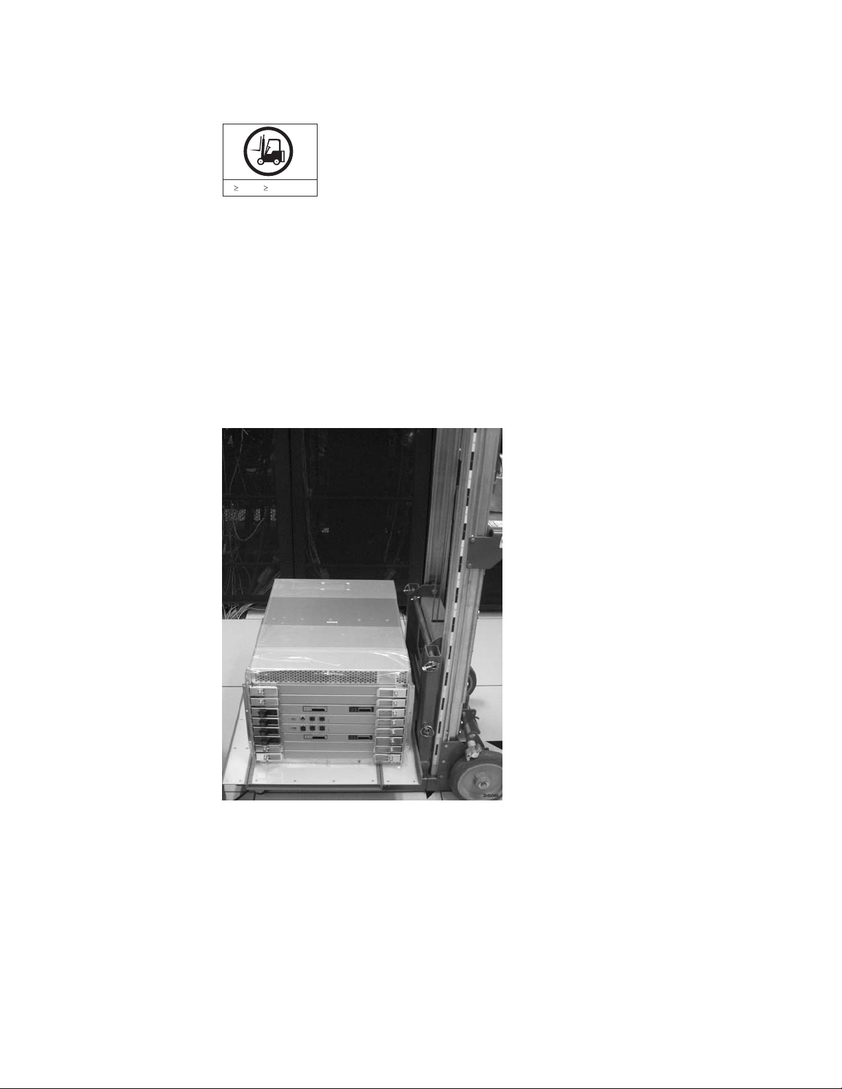
Installing the SAN384B into the cabinet
CAUTION:
A fully populated SAN384B weighs approximately 68 kg (150 lb) and
requires a minimum of two people and a lift tool to install it. (C011)
55 kg ( 121.2 lbs)
svc00169
Now that the port-side exhaust kit is securely installed, the SAN384B chassis can
be safely installed into the C36 cabinet. Perform the following steps to install the
chassis.
Note: The cabinet should already be fully installed, with leveling legs lowered to
prevent it from moving during the chassis installation.
1. Move the lift tool to a position as close as possible to the rear of the cabinet.
Position the lift tool so that the blower assemblies are facing towards the
inside of the cabinet and the port side of the chassis facing away from the
cabinet (see Figure 11).
Figure 11. Lift tool and chassis positioned at rear of cabinet
2. Set the wheel brake by pressing down on the wheel brake pedal.
3. Remove the lift tool retention straps from the chassis and the lift tool.
4. Carefully center the chassis over the middle section of the lift tool load plate.
5. Turn the lift tool winch handle clockwise to raise the load plate and chassis to
approximately 2 cm (3/4 in.) above the height of the port side exhaust kit
shelf.
6. Rotate the winch handle 1/4 turn counter clockwise to lock the winch.
24 SAN384B Installation, Service, and User Guide
Page 53

7. Release the two spring-loaded pins on the under side of the load plate and
slide the middle section as far as possible into the cabinet until it stops. The
chassis should not move with the middle section.
Note: If the chassis is not carefully centered over the middle section, the
weight of the chassis may prevent the middle section from sliding.
Adjust the alignment if needed.
8. Release the spring-loaded pin closest to the cabinet one more time, and slide
the middle section to its full extension. Make sure the spring-loaded pin snaps
back into place. The gap between the end of the load plate middle section and
the port side exhaust kit shelf should be no more than 2.5 cm (1 in.). If the
gap is larger than this, either the lift tool is not positioned close enough to the
cabinet, or the load plate middle section is not fully extended. Adjust as
needed. Figure 12 shows a view from inside the cabinet, with the middle
section of the lift tool load plate extended, and the chassis centered on the
load plate.
Figure 12. Load plate extended inside the cabinet to the exhaust kit shelf
9. Carefully slide the chassis into the cabinet between the shelf and the upper
edge of the exhaust kit duct assembly until the chassis rests securely on the
shelf. Figure 13 on page 26 shows a view from outside the cabinet with the
middle of the load plate fully extended and the chassis pushed approximately
half way into the cabinet. Reposition the nut clips installed earlier if necessary.
Push the chassis all the way into the cabinet until the flanges on the port side
of the chassis are firmly against the cabinet vertical rails.
Note: If necessary, adjust the height of the load plate to allow a smooth
transfer of the chassis from the extended load plate to the top of the
shelf.
Chapter 2. Installing a SAN384B in a cabinet 25
Page 54

Figure 13. Chassis half way into cabinet on load plate
Note: For rails with round holes, use the clip nuts (F in Figure 6 on page 19)
on the rails for securing the 10-32 screws. For rails with square holes,
use the retainer nuts (G Figure 6 on page 19). Also refer to Figure 7 on
page 21.
10. Release the spring-loaded pins under the load plate, and slide the middle
section of the load plate back into load plate.
11. Lower the lift plate to its lowest position, release the wheel brake on the lift
tool, and move the lift tool away from the cabinet.
12. If necessary, adjust the rubber strips on the exhaust kit duct to ensure a good
seal against the chassis.
13. The chassis will be secured to the cabinet with six 10-32 screws with washers
(see Figure 14 on page 27). Four of these screws will also be used to attach the
cable management finger assemblies. Do not install the screws until you
determine the position of the cable management fingers.
Note: Screws, clip nuts, and retainer nuts to secure the chassis to the cabinet
are provided in the SAN384B hardware accessory kit.
26 SAN384B Installation, Service, and User Guide
Page 55

Install screws
Figure 14. Location of screws to attach the chassis to the cabinet rails
Install screws
384b038
14. Attach the two cable management finger assemblies to the cabinet vertical
rails, using two screws each. The two assemblies are identical and can be
installed on either side. The screws will extend through the chassis flange
used to attach the chassis to the cabinet rails, and into the clip nuts you have
installed. Select the holes on the cable management assemblies that match two
of the holes on the chassis flange. You will be able to position the cable
management finger assemblies either towards the top of the chassis or
towards the bottom of the chassis, depending on your requirements for
routing cables. The third screw for each side is used to secure the chassis to
the rails, directly through the chassis flange into the clip nuts. These screws
do not attach the cable management assemblies to the chassis or rack.
Figure 15 on page 28 shows the cable management fingers positioned towards
the top of the chassis.
Chapter 2. Installing a SAN384B in a cabinet 27
Page 56
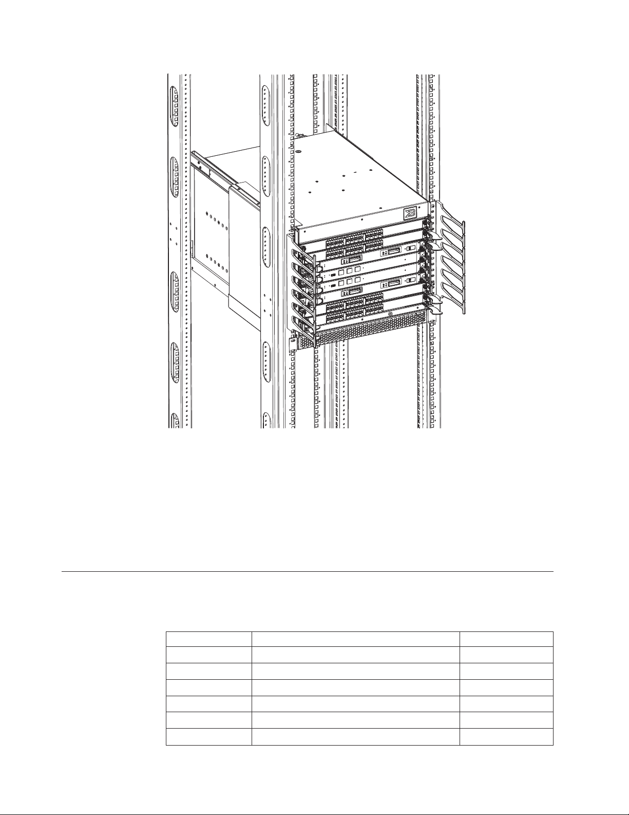
Port numbering
|
384b016
Figure 15. Attaching the vertical cable management finger assemblies to the cabinet rails
15. Disassemble and pack the lift tool into the shipping crate. Follow the return
instructions provided.
Note: For turning on the power and for the configuration instructions, see
Chapter 3, “Starting and configuring the SAN384B,” on page 33.
Attention: Do not connect the SAN384B to the network until the IP addresses are
correctly set.
Table 7 provides a list of available port blades for the SAN384B.
Table 7. Port blades available on the SAN384B
Blade label IBM blade name Feature code
FC8-16 16 port 8Gb Switch Blade 3816
FC8-32 32 port 8Gb Switch Blade 3832
FC8-48 48 port 8Gb Switch Blade 3848
FC8-64 64 port 8Gb Switch Blade 3864
FC10-6 10Gb Fibre Channel Blade 3870
FR4-18i FC Routing Blade 3850
28 SAN384B Installation, Service, and User Guide
Page 57

Table 7. Port blades available on the SAN384B (continued)
Blade label IBM blade name Feature code
FX8-24 FCIP extension blade 3890
FCoE10-24 Fibre Channel over Ethernet blade 3880
The SAN384B uses the following port numbering for each of the blades that can be
|
|
|
|
installed in the chassis. See illustrations of the different blades in Appendix D,
“Blade port numbering,” on page 137. Refer to Implementing an IBM/Brocade SAN
with 8 Gbps Directors and Switches, (an IBM Redbook), SG24-6116 for more details
on port numbering and other technical information.
Note: Blades are installed in a horizontal orientation in the SAN384B chassis, so
the normal top of the blade is oriented to the left, and the normal bottom of
the blade is oriented to the right when the blades are installed in the chassis.
v FC8-16 port blade - Ports are numbered from 0 through 15 from right to left.
v FC8-32 port blade - Ports are numbered from 0 through 15 from right to left on
the lower row of ports and 16 through 31 from right to left on the upper row of
ports.
v FC8-48 port blade - Ports are numbered from 0 through 23 from right to left on
the lower row of ports and 24 through 47 from right to left on the upper row of
ports.
|
|
|
|
|
v FC8-64 port blade - Ports are numbered from 0 through 31 from right to left on
the lower row of ports and 32 through 63 from right to left on the upper row of
ports. See Figure 54 on page 138 for an illustration of the blade. Trunking groups
are permitted with up to eight ports per group. Trunking groups are as follows:
0-7, 8-15, 16-23, 24-31, 32-39, 40-47, 48-55, and 56-63.
v FC10-6 port blade - Ports are numbered from 0 through 5 from right to left.
v FR4-18i router blade - The 16 physical Fibre Channel ports are numbered from 0
through 15 from right to left. The two GbE ports, numbered GE0 and GE1, are
located to the right of the Fibre Channel ports. These ports, when fully
configured, enable 16 VE_ports or VEX_ports and appear in the switchShow
command as ports 16 through 31.
v FX8-24 FCIP extension blade - The port numbering scheme is fairly complex for
this blade, but is displayed for reference on the blade itself in a diagram towards
the right end of the blade (see Figure 57 on page 139). There are twenty-four
physical ports. Twelve FC ports are located towards the right end of the blade,
with ports 0 through 5 in the lower row, and ports 6 through 11 in the upper
row. Two 10 Gigabit Ethernet (10GbE or XGE) ports are located in the lower row
of ports and are numbered 0 and 1, from right to left. Ten GbE ports are located
towards the left end of the blade, with eight clustered to the far left, and the
remaining two located above the two 10GbE ports. The GbE ports 0 through 3,
numbered from right to left are located in the lower row to the far left side of
the blade. Ports 4 and 5 are located above the two 10GbE ports, and ports 6
through 9 (numbered right to left) are in the top row above ports 0 through 3.
|
|
|
|
|
Up to three FC trunking groups. The three groups are defined as:
– Trunk group 0: FC ports 0, 1
– Trunk group 1: FC ports 6, 7
– Trunk group 2: FC ports 2, 3, 4, 5, 8, 9, 10, 11
–
Chapter 2. Installing a SAN384B in a cabinet 29
Page 58

|
Chassis slots
v FCoE10-24 FC over Ethernet blade - The 24 physical ports are numbered 0
through 11 from right to left on the lower row of ports and 12 through 23 from
right to left on the upper row of ports.
|
|
|
|
|
|
|
|
|
|
|
Cable organization
|
|
|
Slots are numbered 1 through 8, from bottom to top of the chassis when facing the
port side of the SAN384B. Control processor blades (CP8) can be installed only in
slots 4 and 5. Core switch blades (CR4S-8) can be installed only in slots 3 and 6.
Port blades can be installed only in slots 1, 2, 7, and 8. Unused slots must be filled
with blade filler panels to maintain adequate cooling.
See Appendix D, “Blade port numbering,” on page 137 for different SAN384B port
blades. Also refer to the IBM Redbook, Implementing an IBM/Brocade SAN with 8
Gbps Directors and Switches, SG24-6116, for more comprehensive information on
port numbering and area port numbering, and other technical information. This
publication is available through www.redbooks.ibm.com/. Search by title or
publication number.
Two vertical cable management finger assemblies (shown in Figure 32 on page 63)
are attached to the rack vertical rails. They are not attached directly to the
SAN384B chassis. This pair of cable management finger assemblies can be used to
keep the cables from hanging down in front of other blades, and to route them
away from the exhaust vent of the port-side exhaust kit, which is located below
the SAN384B chassis.
Route the cables across in front of the blades, keeping the LEDs visible. Leave at
least one meter of slack for each fiber optic cable to provide room to remove and
replace blades.
|
|
|
|
|
|
|
|
|
|
|
|
|
2 3
1
|
Figure 16. Cable design for the mSFP patch cables for the FC8-64 high density port blade
|
|
Attention: Do not route the cables in front of the air exhaust vents, located at the
top and bottom of the port side of the chassis.
The FC8-64 high density port blade cannot use the standard LC cables because the
pitch between optics in the new mSFP transceiver is smaller than in standard SFPs.
Patch cables and panels can be used to attach standard size cabling to the blade if
necessary. Figure 16 illustrates the mSFP to SFP patch cable. The mSFP transceivers
are used only with the FC8-64 port blade. Narrower OM-3 LC cables are used to
connect the FC8-64. These cables are offered by several major manufacturers.
Contact your IBM representative for options regarding different cable and patch
panel configurations to simplify cable management with higher density FC8-64
port blades.
4
b768ig045
30 SAN384B Installation, Service, and User Guide
Page 59

|
||||
||||
1 mini-SFP connector 3 1.6 mm cable
2 Duplex clip (black) 4 SFP connector
|
|
|
|
Note that the duplex clip on the mSFP end of the cable is black for easier
recognition. See Table 26 on page 125 for a listing of the qualified mSFP optical
cables for the FC8-64 port blade.
If ISL Trunking is in use, group the cables by trunking group. The ports are
color-coded to indicate which ports can be used in the same ISL Trunking group:
eight ports marked with solid black ovals alternate with eight ports marked with
oval outlines.
|
|
|
|
Table 26 on page 125 provides a listing of supported cable speeds and distances.
Optional inter-chassis link cables (ICL) can also be installed between two or three
chassis. See “Removing and installing inter-chassis link (ICL) cables” on page 84
for instructions on installing these cables.
Chapter 2. Installing a SAN384B in a cabinet 31
Page 60

32 SAN384B Installation, Service, and User Guide
Page 61

Chapter 3. Starting and configuring the SAN384B
Attention: Refer to the latest Fabric OS Release Notes or Interoperability Matrix
for information regarding Fabric OS compatibility. This is particularly important
for fabrics with 1-Gbps switches using earlier Fabric OS versions. To access the
appropriate matrix:
v Go to the IBM SAN web page www.ibm.com/systems/storage/san
v Select the SAN384B product link
v On the SAN384B product page, click the Interoperability Matrix link.
The SAN384B must be configured before it is connected to the fabric, and all of the
configuration commands must be entered through the active CP blade. The
SAN384B configuration includes the following parameters:
v IP address and subnet mask for the SAN384B
v IP addresses, host names, subnet masks, and gateway addresses for both CP
blades
v Switch name
v Domain ID (optional)
v WWN (optional)
Note: The SAN384B WWN is initially set by the factory to match the license ID
(which is based on the chassis serial number). The WWN can be changed,
but the license ID cannot be modified.
The configuration information is mirrored to the standby CP blade, which allows
the most current configuration to remain available even if the active CP blade fails.
The configuration information for the SAN384B is stored in the WWN cards and
the flash memory of the CP blades. The configuration can be backed up to a
workstation (uploaded) and then downloaded to the active CP blade if necessary.
Figure 17 on page 34 provides an overview of the sequence of tasks to configure
the SAN384B.
© Copyright IBM Corp. 2009, 2010 33
Page 62

Configuration Tasks
Connect Serial Cable
between Switch and Host
Log In to Serial Console Port
Set IP Address
Log off Serial Console Port
and Disconnect Serial Cable
Connect Ethernet Cable
and Open Telnet Session
Set Domain ID
Set Date and Time
Install SFPs and
Attach Cables
Manage Cables
Verify Operation and
Back Up Configuration
Figure 17. Flow of configuration tasks for the SAN384B
384b004
The initial physical hardware installation continues with the following steps:
v “Providing power to the SAN384B” on page 35
v “Connecting the SAN384B and host with a serial cable” on page 35
v “Logging in to the serial console port” on page 36
v “Configuring the IP addresses” on page 36
|
|
v Installing optical transceivers and cables (see “Removing and installing
transceivers” on page 81 and “Managing cables” on page 42)
The following additional steps are customer responsibilities required for the initial
configuration:
1. Establish an Ethernet connection. See “Establishing an Ethernet connection” on
page 38.
2. Specify a switch name. See “Customizing the switch name” on page 38.
3. Specify a domain ID for the SAN384B. See “Setting the Domain ID” on page
39.
4. Set the date and time. See “Setting the date and time” on page 39.
|
|
5. Connect to the fabric. See “Verifying the PID mode and connecting to the
fabric” on page 41
34 SAN384B Installation, Service, and User Guide
Page 63

6. Enable software licenses. See “Software licenses” on page 41.
7. Back up the configuration. See “Verifying correct operation and backing up the
configuration” on page 43.
Providing power to the SAN384B
DANGER
An electrical outlet that is not correctly wired could place hazardous voltage
on the metal parts of the system or the devices that attach to the system. It is
the responsibility of the customer to ensure that the outlet is correctly wired
and grounded to prevent an electrical shock. (D004)
Attention: Use only the supplied power cords.
To provide power to the SAN384B:
1. Connect the two AC power cords to each of the two power supplies.
2. Connect the power cords to a power source with a voltage of 200 to 240 VAC,
47 to 63 Hz..
3. Turn the AC power switches on the power supplies to ON (|). The AC power
switches light green when switched on and power is supplied.
4. The SAN384B performs a power-on self-test (POST) each time it is powered on.
POST takes approximately 10 minutes and is complete when indicator light
activity displays the operational state. For information about LED patterns, see
Chapter 4, “Monitoring system components,” on page 45.
You can bypass POST by using the fastBoot command. You can also disable
POST for successive reboots on the SAN384B using the diagDisablePost
command.
Attention: To prevent a potential IP address conflict, do not connect the
SAN384B to the network until the IP addresses are configured.
Note: To power off the SAN384B, see “Powering off the SAN384B” on page 44.
Connecting the SAN384B and host with a serial cable
Follow these steps to connect a serial cable.
1. Verify that the SAN384B is powered on and that POST is complete by
confirming that all power LED indicators on the port, control processor, and
core switch blades display a steady green light.
2. Remove the shipping cap from the CONSOLE port on the active CP. Use the
serial cable provided with the product to connect the CONSOLE port on the
active CP to a computer workstation. The active CP blade is indicated by an
illuminated (blue) LED.
Attention: The CONSOLE port is intended primarily for the initial setting of
the IP address and for service purposes.
3. Access the SAN384B using a terminal emulator application (such as
HyperTerminal in a Windows environment or TIP in a UNIX environment).
4. Disable any serial communication programs running on the workstation (such
as synchronization programs).
Chapter 3. Starting and configuring the SAN384B 35
Page 64

5. Open the terminal emulator application and configure as follows:
v In a Windows environment:
Table 8. Configuration parameters
Parameter Value
Bits per second 9600
Data bits 8
Parity None
Stop bits 1
Flow control None
v In a UNIX®environment, enter the string at the prompt:
term /dev/ttyb -9600
If ttyb is already in use, use ttya instead and enter the following string at the
prompt:
term /dev/ttya -9600
Logging in to the serial console port
To log in to the SAN384B through the serial connection, follow these steps.
1. When the terminal emulator application stops reporting information, press
Enter. You will receive the following login prompt: CP0 Console Login:
2. Log in to the SAN384B as admin. The default password is "password." At the
initial login, you are prompted to change the default passwords. Record the
new passwords and keep this information in a secure location. The example
below shows the login without changing the password.
swDir login: admin
Password:
Please change your passwords now.
Use Control-C to exit or press 'Enter' key to proceed.
Password was not changed. Will prompt again at next login
until password is changed.
swDir:admin>
3. (Optional) Modify passwords. To skip modifying the password, press Ctrl+C
.Passwords can be 8 to 40 characters long. They must begin with an alphabetic
character. They can include numeric characters, the dot (.), and the underscore
(_). Passwords are case-sensitive, and they are not displayed when you enter
them on the command line. For more information on passwords, refer to the
Fabric OS Administrator’s Guide.
Configuring the IP addresses
The SAN384B requires three IP addresses, which are configured using the
ipAddrSet command. IP addresses are required for both CP blades (CP0 and CP1)
and for the single logical switch (shown as SWITCH under the ipAddrShow
command) in the
Note: The default IP addresses and host names for the SAN384B are as follows:
v 10.77.77.75 for CP0 (the CP blade in slot 4 at the time of configuration)
v 10.77.77.74 for CP1 (the CP blade in slot 5 at the time of configuration)
36 SAN384B Installation, Service, and User Guide
Page 65

Attention: Resetting an IP address while the SAN384B has active IP traffic such
as Fabric Manager, Fabric Watch, SNMP, or other applications can cause traffic to
be interrupted or stopped. Changing the IP address causes a domain address
format RSCN to be issued.
Follow these steps to configure the IP addresses for both CP blades (from the
active CP blade):
1. Log in to the active CP as admin using the serial cable connection.
2. Set up the SAN384B IP address by entering the ipaddrset -chassis command at
the prompt.
swDir:admin> ipAddrSet -chassis
Enter the information at the prompts. Specify the -chassis IP address. The -sw
0 IP address is no longer valid on this chassis.
Note: The addresses 10.0.0.0 through 10.0.0.255 are reserved and used
internally by the SAN384B. External IPs must not use these addresses.
3. Set up the CP0 blade IP address by entering the ipaddrset -cp 0 command at
the prompt.
swDir:admin> ipAddrSet -cp 0
Enter the requested information at the prompts.
4. Set up the CP1 IP address by entering the ipaddrset -cp 1
command:swDir:admin> ipAddrSet -cp 1
Enter the requested information at the prompts.
The following is a sample IP configuration, for the SAN384B (sw -0) and the
two CP blades (cp0 and cp1):
swDir:admin> ipaddrset -chassis
Ethernet IP Address [0.0.0.0]: 123.123.123.120
Ethernet Subnetmask [0.0.0.0]: 123.123.123.123
Fibre Channel IP Address [0.0.0.0]:
Fibre Channel Subnetmask [0.0.0.0]:
Issuing gratuitous ARP...Done.
Committing configuration...Done.
swDir:admin> ipaddrset -cp 0
Host Name [cp0]:
Ethernet IP Address [10.77.77.75]: 123.123.123.121
Ethernet Subnetmask [0.0.0.0]: 123.123.123.123
Gateway IP Address [0.0.0.0]: 123.123.123.124
IP address is being changed...Done.
Committing configuration...Done.
swDir:admin> ipaddrset -cp 1
Host Name [cp1]:
Ethernet IP Address [10.77.77.74]: 123.123.123.122
Ethernet Subnetmask [0.0.0.0]: 123.123.123.123
Gateway IP Address [0.0.0.0]: 123.123.123.124
IP address of remote CP is being changed...Done.
Committing configuration...Done.
swDir:admin> reboot
5. Enter reboot to reboot the SAN384B.
Logging off the serial console port and disconnecting the serial cable
You can use the serial port to monitor error messages through the serial
connection, however it is generally used for initial configuration and service
Chapter 3. Starting and configuring the SAN384B 37
Page 66

purposes. If the serial port is no longer required, use the logout command to log
out of the serial console, remove the serial cable, and replace the plug in the serial
port.
Establishing an Ethernet connection
After using a serial connection to configure the IP addresses for the SAN384B, you
can connect the active CP blade to the local area network (LAN).
Note: Connecting the CP blades to a private network/VLAN is recommended.
By establishing an Ethernet connection, you can complete the SAN384B
configuration using a serial session, Telnet , or through a management application
such as Web Tools or DCFM.
To establish an Ethernet connection to the SAN384B, follow these steps:
1. Remove the shipping plug from the Ethernet port on the active CP blade.
2. Insert one end of an Ethernet cable into the Ethernet port.
3. Connect the other end to an Ethernet 10/100/1000 BaseT LAN.
The SAN384B can now be accessed by remote connection using any of the
available management tools, such as Telnet, Web Tools, or DCFM.
4. To complete any additional SAN384B configuration procedures through a
Telnet session, log in to the SAN384B by Telnet, using the admin login. The
default password is password.
Customizing the switch name
|
|
The switch name of the SAN384B can be up to 30 characters long as of Fabric OS
release 6.3.0; can include letters, numbers, and underscore characters; and must
begin with a letter. Fabric OS releases earlier than 6.3.0 require switch names of 15
characters or less.
Note: Changing the name causes a domain address format RSCN to be issued.
To customize the name, follow these steps:
1. Enter the switchName command with the new name in quotes.
swDir:admin> switchName "ModularSwitch5"
Committing configuration...
Done.
ModularSwitch5:admin
2. Record the new name for future reference.
Customizing a chassis name
For Fabric OS 6.2.0 and later, the chassis name of the SAN384B can be up to 15
characters long; can include alpha, numeric, and underscore characters; and must
begin with an alpha character.
1. Enter chassisName followed by the new name in double quotes.
switch:admin> chassisname "SAN384B_chassis_1"
Committing configuration...
Done.
2. 2. Display the new chassis name.
38 SAN384B Installation, Service, and User Guide
Page 67

switch:admin> chassisname SAN384B_chassis_1
3. Record the new name for reference.
Setting the Domain ID
Each switch in the fabric must have a unique Domain ID. The Domain ID can be
set using the configure command or can be automatically set. The default Domain
ID for the SAN384B is "1". Use the fabricShow command to view the already
assigned domain IDs.
To set the Domain ID, follow these steps:
1. Enter the switchDisable command to disable the SAN384B.
2. Enter the configure command.
3. Enter y at the "Fabric parameters" prompt:
Fabric parameters (yes, y, no, n): [no] y
4. Enter a unique Domain ID:
Domain: (1.239) [1] 3
5. Complete the remaining prompts or press Ctrl+D to accept the settings and to
exit.
6. Enter the switchEnable command to re-enable the SAN384B.
Setting the date and time
The date and time settings are used for logging events. Switch operation does not
depend on the date and time; a switch with an incorrect date and time value still
functions properly. However, because the date and time are used for logging, error
detection, and troubleshooting, they should be set correctly.
Setting the date
To set the date, follow these steps.
1. If necessary, log on to the SAN384B by Telnet, using the admin account.
2. Enter the date command, using the following syntax:date "mmddHHMMyy"
Where:
v mm is the month; valid values are 01 through 12.
v dd is the date; valid values are 01 through 31.
v HH is the hour; valid values are 00 through 23
v MM is minutes; valid values are 00 through 59.
v yy is the year; valid values are 00 through 99 (values greater than 69 are
interpreted as 1970 through 1999, and values less than 70 are interpreted as
2000-2069).
switch:admin> date
Fri Sep 26 17:01:48 UTC 2008
switch:admin> date "0926123008"
Fri Sep 26 12:30:00 UTC 2008
switch:admin>
Setting the time zone
To set the time zone, follow these steps.
1. If necessary, log on to the switch by Telnet, using the admin account.
Chapter 3. Starting and configuring the SAN384B 39
Page 68

2. Enter the tsTimeZone command as follows:
switch:admin> tstimezone [--interactive]/ [, timezone_fmt]
Use timezone_fmt to set the time zone by Country/City or by time zone ID,
such as MST.
The following example shows how to change the time zone to US/Mountain.
switch:admin> tstimezone
Time Zone : US/Pacific
switch:admin> tstimezone US/Mountain
switch:admin> tstimezone
Time Zone : US/Mountain
The following procedure describes how to set the current time zone using
interactive mode.
1. Enter the tsTimeZone command as follows:
switch:admin> tstimezone --interactive
You are prompted to select a general location.
Please identify a location so that time zone rules can be set correctly.
2. Enter the appropriate number or Ctrl+D to quit.
3. At the prompt, select a country location.
4. At the prompt, enter the appropriate number to specify the time zone region or
Ctrl+D to quit.
Synchronizing local time
To synchronize the local time of the principal or primary switch with that of an
external NTP server, follow these steps.
1. If necessary, log on to the switch by Telnet, using the admin account.
2. switch:admin> tsclockserver "<ntp1;ntp2>"
where ntp1 is the IP address or DNS name of the first NTP server, which the
switch must be able to access. The variable ntp2 is the second NTP server and
is optional. The operand "<ntp1;ntp2>" is optional; by default, this value is
LOCL, which uses the local clock of the principal or primary switch as the
clock server.
The tsClockServer command accepts multiple server addresses in either IPv4,
IPv6, or DNS name formats. When multiple NTP server addresses are passed,
tsclockserver sets the first obtainable address as the active NTP server. The rest
will be stored as backup servers that can take over if the active NTP server
fails. The principal or primary FCS switch synchronizes its time with the NTP
server every 64 seconds.
switch:admin> tsclockserverLOCL
switch:admin> tsclockserver "132.163.135.131"
switch:admin> tsclockserver
132.163.135.131
switch:admin>
The following example shows how to set up more than one NTP server using a
DNS name:
switch:admin> tsclockserver "10.32.170.1;10.32.170.2;ntp.localdomain.net"
Updating Clock Server configuration...done.
Updated with the NTP servers
Changes to the clock server value on the principal or primary FCS switch are
propagated to all switches in the fabric
40 SAN384B Installation, Service, and User Guide
Page 69

Verifying the PID mode and connecting to the fabric
|
|
|
|
|
|
|
|
|
|
|
|
Software licenses
To verify PID mode, connect the system to the fabric and verify status, follow these
steps:
1. Before connecting the SAN384B to the fabric, verify that the port identifier
(PID) mode on the SAN384B matches the other switches in the fabric. This
parameter must be set identically on all switches in the fabric. This parameter
is set using the configure command. For information on PID mode, refer to the
Fabric OS Administrator's Guide.
2. Verify the chassis and port status by entering the switchShow command. This
command provides detailed information about the SAN384B.
3. Verify fabric connectivity by entering the fabricShow command. This command
provides general information about the fabric.
Certain licenses may be factory installed on the SAN384B. To determine which
licenses are currently enabled, use the licenseShow command.
swDir:admin> licenseshow
AAbbccDDeeFFeeGG:
Web license
Zoning license
Extended Fabric license
Fabric Watch license
Performance Monitor license
Trunking license
Security license
In the example above, the license key is AAbbccDDeeFFeeGG. Keep a copy of the
license key for reference.
The 64-bit chassis ID is required to obtain and activate licenses for the SAN384B.
The chassis ID is available through the licenseIdShow command.
The licenseShow and licenseIdShow commands must be entered on the active CP
blade.
Refer to the Fabric OS Administrator's Guide for more information.
Installing transceivers and attaching cables
|
|
|
|
|
|
|
|
|
|
|
Follow these steps to install SFPs, SFP+s, mSFPs (FC8-64 port blade only), or XFPs
(FC10-6 port blade only) and cables to the blades and chassis.
Note: For a listing of transceivers compatible with this product:
v Go to the IBM SAN web page www.ibm.com/systems/storage/san
v Select the SAN384B product link
v On the SAN384B product page, click the Interoperability Matrix link.
v In the Interoperability matrix, click the Transceivers link.
Attention: mSFP transceivers are compatible only with the FC8-64 port blade.
While they will fit in other blades, this configuration is unsupported and will
generate an error.
Chapter 3. Starting and configuring the SAN384B 41
Page 70

|
|
|
|
|
|
|
|
|
|
|
|
|
|
|
|
|
|
|
|
Managing cables
|
The ports are color-coded to indicate which can be used in the same port group for
trunking (trunking port groups can be up to eight ports). The ports and cables
used in trunking groups must meet specific requirements. Refer to the Fabric OS
Administrator’s Guide for more information.
1. Position one of the optical transceivers so that the key is oriented correctly to
the port. Insert the transceiver into the port until it is firmly seated and the
latching mechanism clicks.
Transceivers are keyed so that they can only be inserted with the correct
orientation. If a transceiver does not slide in easily, ensure that it is correctly
oriented.
2. Position a cable so that the key (the ridge on one side of the cable connector) is
aligned with the slot in the transceiver; then, insert the cable into the
transceiver until the latching mechanism clicks.
Cables are keyed so that they can only be inserted with the correct orientation.
If a cable does not slide in easily, ensure that it is correctly oriented.
3. Repeat steps 1 and 2 for the remaining ports.
4. Organize the cables as required. For recommendations regarding cable
management, refer to “Managing cables.”
5. Verify the chassis and port status using the switchShow command.
6. Verify fabric connectivity using the fabricShow command.
|
|
|
|
|
|
|
|
|
|
|
|
|
|
|
|
|
|
|
|
|
Attention: The minimum bend radius should be no smaller than 10x the cable
radius.
Note: Contact your IBM representative for options regarding different cable and
patch panel configurations to simplify cable management with higher
density FC8-64 port blades.
Cable management recommendations:
v Leave at least 1 m (3.28 ft) of slack for each port cable. This provides room to
remove and replace blades in the chassis, allows for inadvertent movement of
the rack, and helps prevent the cables from being bent to less than the minimum
bend radius.
v If ISL Trunking is in use, group the cables by trunking group. The ports are
color-coded to indicate which ports can be used in the same ISL Trunking group:
eight ports marked with solid black ovals alternate with eight ports marked with
oval outlines.
v Use only hook-and-loop fasteners for securing cables. Do not use cable ties. They
can be easily overtightened and can break the optical cables.
v For easier maintenance, label the fiber optic cables and record the devices to
which they are connected.
v Use the cable management fingers attached to the rack rails to organize the
cables off to the side of the chassis, and away from the chassis exhaust vents.
v Keep LEDs visible by routing port cables and other cables away from the LEDs.
|
|
For the procedure to install the ICL cables see “Removing and installing
inter-chassis link (ICL) cables” on page 84.
42 SAN384B Installation, Service, and User Guide
Page 71

Verifying correct operation and backing up the configuration
To verify correct operation and to back up the system, follow these steps.
1. Check the LEDs to verify that all components are functional. For information
about LED patterns, see Chapter 4, “Monitoring system components,” on page
45.
2. If necessary, log on to the switch by Telnet, using the admin account.
3. Verify the correct operation of the system by entering the switchShow
command from the workstation. This command provides information about
switch and port status.
4. Verify the correct operation of the SAN384B in the fabric by entering the
fabricShow command from the workstation. This command provides general
information about the fabric.
|
|
|
|
|
|
|
5. To back up the configuration, run the following two steps:
a. Enter the configupload -vf command. This command uploads the system
virtual fabric data.
b. Enter the configupload command. This command uploads the system
configuration.
6. Run the following commands to see additional configuration information that
you can then copy to a file to save:
v configShow
v ipAddrShow
v licenseShow
v switchShow
Note: Passwords are not saved in the configuration file, and are not uploaded
during a configUpload. Password information should be saved in hardcopy
in a secure location for reference, subject to your security and password
management policy.
Note: It is recommended that the configuration be backed up on a regular basis to
ensure that a complete configuration is available for downloading to a
replacement device.
Fabric OS firmware updates
To ensure optimum functioning of your system, IBM recommends operating your
system with the latest Fabric OS version and firmware updates. Refer to the latest
Fabric OS Release Notes and Interoperability Matrix for information regarding
Fabric OS compatibility. This is particularly important for fabrics with 1-Gbps
switches using earlier Fabric OS versions. Detailed information on downloading
and installing firmware are provided in the Fabric OS Administrator's Guide.
To access the appropriate matrix:
v Go to the IBM SAN web page www.ibm.com/systems/storage/san
v Select the SAN384B product link
v On the SAN384B product page, click the Interoperability Matrix link.
Firmware release notes and download files are available through the IBM SAN
Support web pages.
To view release notes and to download firmware:
Chapter 3. Starting and configuring the SAN384B 43
Page 72

v Go to www.ibm.com/systems/support.
v Select System Storage.
v On the next page that is displayed, select Download, and then select Storage
area network (SAN).
v Select your product, then in the Recommended fix section, select the
appropriate firmware version release notes. Review the release notes before
installing the firmware update.
v Select the firmware download version and follow the online prompts.
Downloading and installing firmware
1. The firmware version on both the active and backup CP blade should match,
and should be at the latest level. If High Availability is enabled (haEnable), the
system will automatically update the firmware level on both CP blades.
Attention: Firmware downloads require Ethernet connections to both CP
blades. Procedures for loading downloading and installing firmware are fully
described in the Fabric OS Administrator's Guide.
2. When you have navigated to the appropriate download site, follow the online
instructions on the displayed Fabric OS download pages, referring to the Fabric
OS Administrator's Guide as needed.
3. Enter firmwareDownload -s on your to download the firmware to one of the
CP blades from your server.
Powering off the SAN384B
If you need to power off the SAN384B, follow these steps to avoid loss of data.
1. Shut down the SAN384B using the sysShutdown command.
switch::admin> sysshutdown
This command will shutdown the operating systems on your switch.
You are required to power-cycle the switch in order to restore operation.
Are you sure you want to shutdown the switch [y/n]? y
HA is disabled
Stopping blade 1
Shutting down the blade....
Stopping blade 2
Shutting down the blade....
Stopping blade 8
Shutting down the blade....
Broadcast message from root (pts/1) Tue Aug 23 14:23:06 2008...
The system is going down for system halt NOW !!
2. Power off the chassis by flipping the AC power switches on the power supplies
to "O". The LEDs inside AC power switches should turn off. To maintain the
ground connections, leave the power cords connected to the power supplies
and to the electrical outlets.
44 SAN384B Installation, Service, and User Guide
Page 73

Chapter 4. Monitoring system components
The SAN384B is engineered for reliability and requires no routine operational steps
or maintenance. This chapter provides information about determining the status of
the following components using LEDs and CLI commands. Refer to the Fabric OS
Administrator's Guide and the Web Tools Administrator's Guide for more information
on monitoring component status.
v “Port or application blade status”
v “Control processor blade (CP8) status” on page 53
v “Core switch blade (CR4S-8) status” on page 55
v “Power supply status” on page 56
v “Blower assembly status” on page 57
v “WWN card status” on page 59
Port or application blade status
To determine the status of a port or routing blade:
1. Check the LEDs on the blade. The illustrations show the blades oriented
horizontally, as they are installed in the SAN384B chassis.
v Figure 18 on page 46 illustrates the FC8-16 port blade
v Figure 19 on page 46 illustrates the FC8-32 port blade
v Figure 20 on page 47 illustrates the FC8-48 port blade
|
v Figure 21 on page 47 illustrates the FC8-64 port blade
v Figure 22 on page 48 illustrates the FC10-6 port blade
v Figure 23 on page 49 illustrates the FR4-18i routing blade
v Figure 24 on page 49 illustrates the FX8-24 extension blade
v Figure 25 on page 49 illustrates the FCOE10-24 Fibre Channel over Ethernet
blade
The LED patterns may temporarily change during POST and other diagnostic
tests. For information about how to interpret the LED patterns, see Table 9 on
page 51.
2. Check the blade status by typing slotShow.
Table 9 on page 51 describes the port and routing blade LED patterns and the
recommended actions for those patterns.
© Copyright IBM Corp. 2009, 2010 45
Page 74

1
2
Figure 18. FC8-16 port blade
1 Status LED 3 Fibre Channel port
2 Power LED 4 Port Status LED
1
2
3
4
384b005
3
4
Figure 19. FC8-32 port blade
1 Status LED 3 Fibre Channel port
2 Power LED 4 Port Status LED
384b006
46 SAN384B Installation, Service, and User Guide
Page 75

3
1
47
!
35
4
8
9
32
33
34
10
11
2
23
!
44204521462247
Figure 20. FC8-48 port blade
|
1
7
11
15
19
40164117421843
36123713381439
328339341035
3
28429530631
1 StatusLED 3 Fibre Channel port
2 Power LED 4 Port Status LED
2
3
4
24025126227
384b007
384b059
|
Figure 21. FC8-64 port blade
|
|
|
|
1 Status LED 3 Fibre Channel port
2 Power LED 4 Port Status LED
Note: The FC8-64 port blade requires narrower OM-3 LC cables offered by several
major manufacturers
Chapter 4. Monitoring system components 47
Page 76
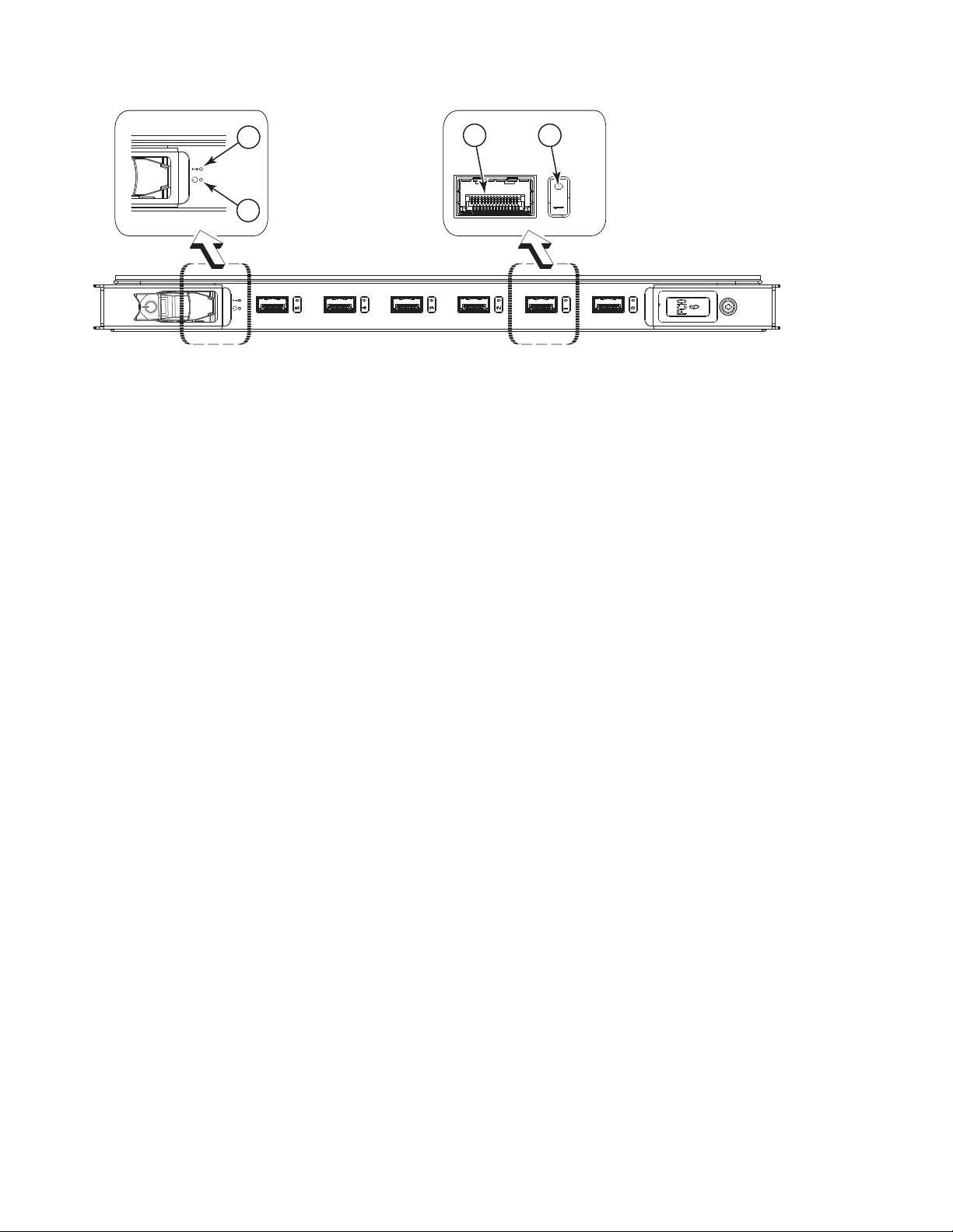
1
2
Figure 22. FC10-6 port blade
1 Status LED 3 Fibre Channel Port
2 Power LED 4 Port Status LED
3
4
384b008
48 SAN384B Installation, Service, and User Guide
Page 77

1
!
2
15
14
!
Figure 23. FR4-18i routing blade
13
1 Status LED 3 Fibre Channel Port
2 Power LED 4 Port Status LED
3
4
7
6
5
4
9
8
7
6
5
4
3
2
0
11
12
10
1
GE1
GE0
18i
FR4
384b009
1
2
Figure 24. FX8-24 extension blade
1 Status LED 5 FC ports 0-5 (numbered right to left)
2 Power LED 6 FC ports 6-11 (numbered right to left)
3 1 GbE ports 0-3 (numbered right
4 10 GbE ports 0-1 (numbered right
|
1
3
to left)
to left)
7
4
6
384b052
5
7 1 GbE ports 4-9 (numbered right to left)
4
384b053
2
|
Figure 25. FCOE10-24 blade
|
|
|
||||
||||
||||
3
1 Power LED 4 Status LED for CEE port 9
2 Status LED 5 CEE port 19
3 CEE port 9 6 Status LED for CEE port 19
Chapter 4. Monitoring system components 49
Page 78

|
50 SAN384B Installation, Service, and User Guide
Page 79

Table 9. Port and routing blade LED descriptions
LED purpose Color Status Recommended Action
Power LED Steady green Blade is enabled. No action required.
No light (LED is off) Blade is not powered on. Ensure that the blade is firmly
seated and either the
thumbscrew is fully engaged
or the slider is pushed up and
the ejectors are fully engaged.
Chapter 4. Monitoring system components
51
Page 80

Table 9. Port and routing blade LED descriptions (continued)
LED purpose Color Status Recommended Action
Status LED FCPort Status No light (LED is off) Blade is either healthy or does
Steady amber Blade is faulty. Ensure blade is firmly seated
not have power.
|
|
|
|
|
Slow-flashing amber (on 2
seconds, then off 2 seconds)
Fast-flashing amber (on 1/2
second, then off 1/2 second)
No light (LED is off) Port has no incoming power,
Steady green Port is online (connected to an
Slow-flashing green (on 1
second, then off 1 second)
Fast-flashing green (on 1/4
second, then off 1/4 second
Flickering green Port is online, with traffic
Steady amber Port is receiving light or signal
Slow-flashing amber (on 2
seconds, then off 2 seconds)
Fast-flashing amber (on 1/2
second, then off 1/2 second)
Alternating green/amber Port is bypassed Reset the port from the
|
|
|
|
Green, amber, off (cycle is
about 1 second)
Amber, amber, pause (cycle is
about 1 second)
Blade is not seated correctly or
is faulty.
Environmental range exceeded. Check for out-of-bounds
or there is no light or signal
carrier detected.
Polling is in progress. Allow 60 seconds for polling to
Connected device is configured
in an offline state.
external device) but has no
traffic.
Port is online but segmented,
indicating a loopback plug or
cable or an incompatible
switch.
Port is in internal loopback
(diagnostic).
flowing through port.
carrier, but it is not online yet.
Port is disabled due to
diagnostic tests or portDisable
or portCfgPersistentEnable
command.
Transceiver or port is faulty. Change the transceiver or reset
Beaconing initiated on the local
switch.
Beaconing initiated on the
HBA and reflected on the port.
Verify that the power LED is
on.
and check the status with the
slotShow command.Blade may
not be compatible with other
blades in the chassis. See
“FCOE10-24 blade” on page
129 for limitations. If the LED
remains amber, contact IBM.
Pull blade out and reseat it. If
the LED continues to flash,
replace the blade.
environmental condition and
correct it.
Verify that the power LED is
on, check the transceiver and
cable.
complete.
Verify the status of the
connected device.
No action required.
Verify that the correct device is
attached to the SAN384B.
No action required.
No action required.
Reset the port from the
workstation using the
portEnable or
portCfgPersistentEnable
command.
Reset the port from the
workstation using the
portEnable or
portCfgPersistentEnable
command.
the switch from the
workstation.
workstation using the
portEnable or
portCfgPersistentEnable
command.
No action required. Beaconing
used to locate/identify port.
No action required. Beaconing
used to locate/identify port.
52 SAN384B Installation, Service, and User Guide
Page 81

Table 9. Port and routing blade LED descriptions (continued)
LED purpose Color Status Recommended Action
GbE Port Status (FX8-24) - both
GbE and 10 GbE ports
10GbE Port Status (FCOE10-24) No light (LED is off) Port is offline. Verify that the power LED is
No light (LED is off) Port has no incoming power,
Steady green Port is online but has no
Slow-flashing green (on 1
second, then off 1 second)
Flickering green Port is online, with traffic
Fast-flashing amber (on 1/4
second, then off 1/4 second)
Steady green Port is online but has no
Flickering green Port is online, with traffic
Steady amber Port is receiving light but it is
Slow-flashing amber (on 2
seconds, then off 2 seconds)
Fast-flashing amber (on 1/4
second, then off 1/4 second)
or there is no light or signal
carrier detected.
traffic.
Beacon. Used to identify
specific ports.
flowing through port.
Transceiver or port is faulty. Change the transceiver or reset
traffic.
flowing through port.
not online yet.
Port is disabled. Enable the port by using the
Transceiver or port is faulty. Change the transceiver or reset
Verify that the power LED is
on, check the transceiver and
cable.
No action required.
No action required.
No action required.
the switch from the
workstation.
on, check the transceiver and
cable.
No action required.
No action required.
Reset the port by doing a
shutdown and no shutdown
sequence from a cmsh session.
no shutdown command from a
cmsh session.
the port by doing a shutdown
and no shutdown sequence
from a cmsh session.
For more information on the CEE Management Shell (cmsh), see the Fabric OS
Command Reference Manual or the Converged Enhanced Ethernet Command Reference.
Control processor blade (CP8) status
To determine the status of a CP blade:
1. Check the LED indicators on the CP blade (see Figure 26 on page 54). The LED
patterns may temporarily change during POST and other diagnostic tests. For
information about how to interpret the LED patterns, see Table 10 on page 54.
2. Check port blade status by typing slotShow and haShow.
Figure 26 on page 54 identifies the control processor blade (CP8).
Chapter 4. Monitoring system components 53
Page 82

2
1
3
Figure 26. Control processor blade (CP8) LEDs
1 Status LED 5 Console port (IOIOI)
2 Power LED 6 Ethernet port (MGMT)
3 USB LED 7 Ethernet port (SERVICE)
4 USB port 8 Active CP LED
Table 10. CP blade LED descriptions
LED purpose Color Status
Power Steady green CP blade has is on. No action required.
Status No light (LED is off) CP blade is either
5
4
6
7
8
No light (LED is off) CP blade does not
on.
healthy or does not
have power.
Steady amber CP blade is faulty or
the switch is still
booting.
Slow-flashing amber
(on 2 seconds; then
off 2 seconds)
Fast-flashing amber
(on 1/2 second; then
off 1/2 second)
CP blade is not
seated correctly or is
faulty.
Environmental range
exceeded.
384b010
Recommended
Action
Ensure that the blade
is firmly seated and
has power.
Verify that the power
LED is on.
Ensure that the blade
is firmly seated and
the switch has
completed booting. If
the LED remains
amber, contact IBM.
Pull the blade out
and reseat it. If the
LED continues to
flash, replace blade.
Check for
out-of-bounds
environmental
condition and correct
it.
54 SAN384B Installation, Service, and User Guide
Page 83

Table 10. CP blade LED descriptions (continued)
Recommended
LED purpose Color Status
Ethernet Link Status No light (LED is off) Either an Ethernet
link is not detected,
or it does not have
incoming power.
Flickering
green/amber
Ethernet Link Speed No light (LED is off) Ethernet link speed is
Steady green Ethernet link speed is
Active CP Steady blue Active CP blade. No action required.
No light (LED is off) Standby CP blade. No action required.
Ethernet link is
healthy and traffic is
flowing through port.
10 Mbps or CP blade
does not have
incoming power.
100/1000 Mbps.
Action
Ensure that the blade
has power, the
Ethernet cable is
firmly seated, and
the connected device
is functioning.
No action required.
Ensure that the CP
has power.
Note: To force a
persistent Ethernet
link speed, type the
ifModeSet
command.
No action required.
Core switch blade (CR4S-8) status
To determine the status of a CR4S-8 core switch blade:
1. Check the LED indicators on the core switch blade (Figure 27). The LED
patterns may temporarily change during POST and other diagnostic tests; for
information about how to interpret the LED patterns, see Table 11 on page 56.
2. Check core switch blade status by entering slotShow and haShow.
Figure 27 shows the CR4S-8 core switch blade and its components.
2
1
Figure 27. Core switch blade (CR4S-8)
3
4
5
384b011
1 Status LED 4 ATTN LED
2 Power LED 5 ICL Connector
3 LINK LED
Chapter 4. Monitoring system components 55
Page 84

Table 11. CR4S-8 blade LED descriptions
Recommended
LED purpose Color Status
Power Steady green CR4S-8 blade is on. No action required.
No light (LED is off) CR4S-8 blade is not
on.
Status No light (LED is off) CR4S-8 is either
healthy or does not
have power.
Steady amber CR4S-8 blade is
faulty or the switch
is still booting.
Slow-flashing amber
(on 2 seconds; then
off 2 seconds)
Fast-flashing amber
(on 1/2 second; then
off 1/2 second)
LINK LED No light (LED is off) No ICL or ICL cable
Steady green ICL connected No action required.
ATTN LED No light (LED is off) ICL is operational No action required.
Blinking amber Attention required Ensure that the ICL
CR4S-8 blade is not
seated correctly or is
faulty.
Environmental range
exceeded.
present, but no
connection.
Action
Ensure blade is
firmly seated and has
power.
Verify that the power
LED is on.
Ensure that the blade
is firmly seated and
the switch has
completed booting. If
the LED remains
amber, contact IBM..
Pull the blade out
and reset it. If the
LED continues to
flash, replace the
blade.
Check for
out-of-bounds
environmental
condition and correct
it.
Ensure that the ICL
cable is correctly
installed.
cable is correctly
installed.
Power supply status
To determine the status of a power supply:
1. Check the LED indicator on the power supply (see Figure 28 on page 57). The
LED patterns may temporarily change during POST and other diagnostic tests;
for information about how to interpret the LED patterns, see Table 12 on page
57.
2. Check the power supply status by entering psShow.
The power supply status displays OK, Absent,orFaulty. If a power supply is
absent or faulty, contact IBM.
56 SAN384B Installation, Service, and User Guide
Page 85

1
Figure 28. Power supply
1 Power LED
Table 12. Power supply LED descriptions
LED purpose Color Status
Power No light (LED is off) Power supply does
not have incoming
power and is not
providing power to
the SAN384B.
Steady green Power supply has
incoming power and
is providing power to
the SAN384B.
Flashing green Power supply is
about to fail.
384b012
Recommended
Action
Ensure that the
power supply is
firmly seated, the
SAN384B has
incoming power,
both power cables
are connected, and
AC power switches
are on.
No action required.
Replace the power
supply.
Blower assembly status
To determine the status of a blower assembly:
1. Check the LED indicators on the blower assembly (see Figure 29 on page 58).
The LED patterns may temporarily change during POST and other diagnostic
tests; for information about how to interpret the LED patterns, see Table 13 on
page 58.
2. Check the blower assembly status using the fanShow command.
The status for each blower assembly displays OK, Absent,orFaulty. The RPM
of each fan in the assembly is also provided. If a blower assembly is absent or
faulty, contact IBM.
Figure 29 on page 58 displays the blower assembly.
Chapter 4. Monitoring system components 57
Page 86

1
Figure 29. Blower assembly LEDs
1 Power LED
2 Fault LED
Table 13. Blower assembly LED descriptions
LED purpose Color Status
Power No Light (LED is off) Blower assembly
does not have power.
Steady green Blower assembly has
power.
Fault No Light (LED is off) Blower assembly is
either healthy or
does not have power.
Steady amber Blower assembly has
a failure (full or
partial).
Slow-flashing amber
(on 2 sec, then off 2
sec)
Flashing amber (on
1/2 sec, then off 3.5
sec)
Fast-flashing amber
(on 1/2 sec, then off
1/2 sec)
Blower assembly is
not seated correctly
or is faulty.
Fan is disabled. Run fanEnable to
Environmental range
exceeded.
2
384b013
Recommended
action
Ensure that the
blower assembly is
firmly seated and has
power.
No action required.
Ensure that the
blower assembly has
power.
Replace the blower
assembly.
Pull the unit out and
reseat it. If the LED
continues to flash,
replace the unit.
enable the fan.
Check for
out-of-bounds
environmental
condition, resolve
any problems, and
reseat the unit. If the
LED continues to
flash, replace the
unit.
58 SAN384B Installation, Service, and User Guide
Page 87
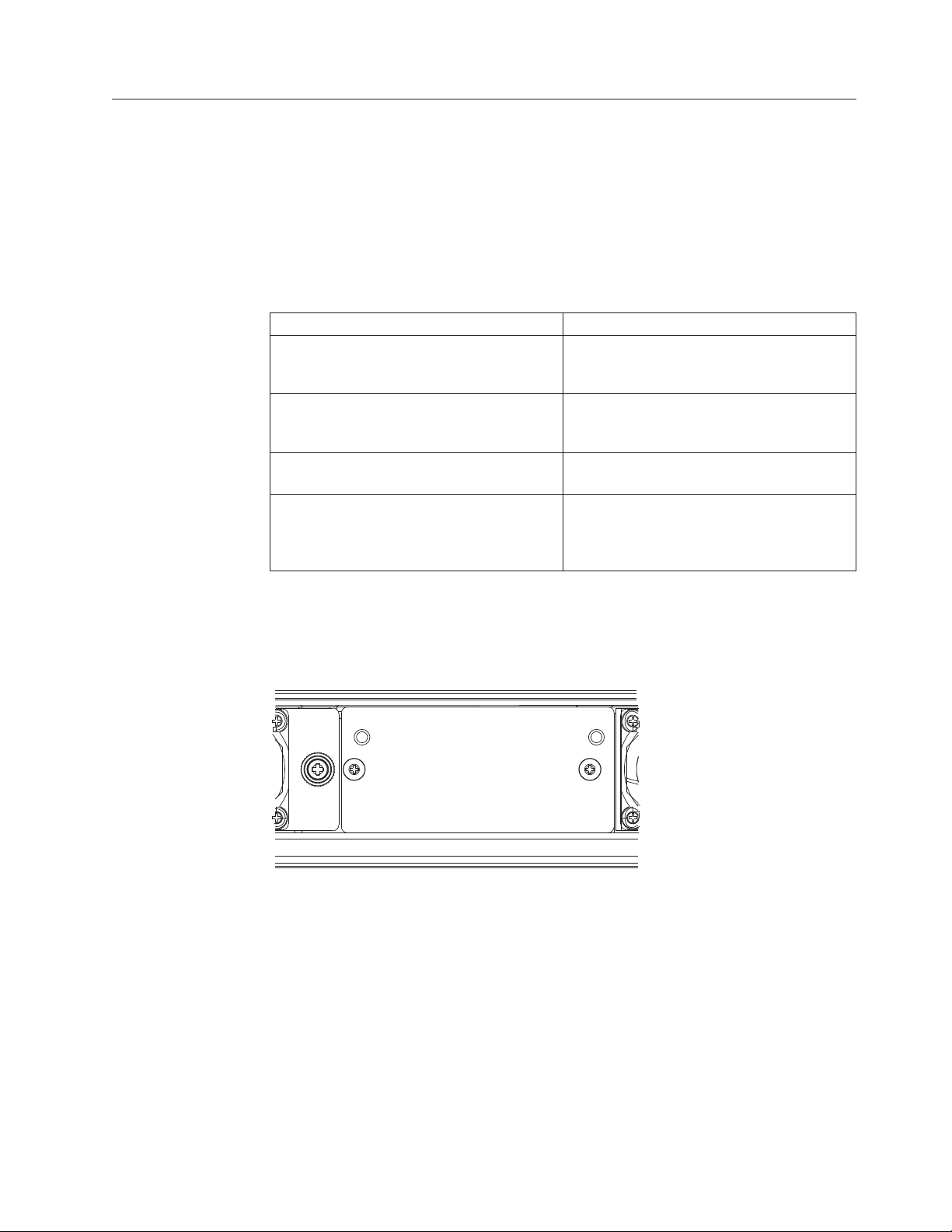
WWN card status
Note: The WWN bezel (see Figure 30) covers the WWN cards. The LEDs on the
To determine the status of the WWN card, enter the chassisShow command to
display information about the WWN card. (WWN units correspond to information
specific to the WWN card.) Error messages that may indicate problems with a
WWN card are summarized in Table 14.
Table 14. Messages that may indicate WWN card failure
Type of Message Sample error message
WWN unit fails its FRU (field replaceable
unit) header access.
WWN unit is being faulted. 0x24c (fabos): Switch: switchname,
WWN unit is not present or is not
accessible.
Writing to the FRU history log
(hilSetFruHistory) has failed.
WWN cards are not visible unless the bezel is removed.
0x24c (fabos): Switch: switchname, error
EM-I2C_TIMEOUT, 2, WWN 1 I2C timed out:
state 0x4
Critical EM-WWN_UNKNOWN, 1, Unknown WWN
#2 is being faulted
0x24c (fabos): Switch: switchname, Error
EM-WWN_ABSENT, 2, WWN #1 not present
0x24c (fabos): Switch: switchname, Error
EM-HIL_FAIL, 2, HIL Error:
hilSetFruHistory failed, rc=-3 for SLOT
3
Figure 30 displays the WWN bezel. The WWN bezel must be removed to reveal
the WWN cards and LEDs. See “Removing and installing a WWN bezel and WWN
card” on page 78 for removal instructions.
384b014
Figure 30. WWN bezel
Chapter 4. Monitoring system components 59
Page 88

60 SAN384B Installation, Service, and User Guide
Page 89

Chapter 5. Removing and installing components
Attention: Read the safety notices before servicing (see “Safety notices and
labels” on page xiii).
The field replaceable units (FRUs) in the SAN384B can be removed and installed
without special tools. The SAN384B can continue operating during many of the
FRU replacements if the conditions specified in the procedures are followed.
The following sections contain FRU removal and installation procedures.
v “Removing and installing the chassis door”
v “Removing and installing cable management finger assemblies” on page 62
v “Removing and installing port and application blades” on page 64
v “Removing and installing blade filler panels” on page 67
v “Removing and installing a CP8 control processor blade” on page 68
v “Removing and installing a CR4S-8 core switch blade” on page 72
v “Removing and installing a power supply” on page 75
v “Removing and installing a blower assembly” on page 77
v “Removing and installing a WWN bezel and WWN card” on page 78
v “Removing and installing transceivers” on page 81
v “Removing and installing inter-chassis link (ICL) cables” on page 84
v “Removing and replacing a SAN384B chassis” on page 91
Removing and installing the chassis door
Note: The chassis door must be installed to ensure the SAN384B meets EMI and
other regulatory certifications. Additionally, if ICL cables are not used, EMI
plugs must be inserted in the ICL cable ports to meet certification standards.
Time and items required
The replacement procedure for the chassis door takes less than 5 minutes.
Removing the chassis door
To remove a chassis door:
1. Support the door to prevent it from falling.
2. Pull and remove the door.
To install a chassis door, align the door and push it into place. See Figure 31 on
page 62.
© Copyright IBM Corp. 2009, 2010 61
Page 90

Figure 31. Chassis door
Removing and installing cable management finger assemblies
The SAN384B comes equipped with two vertical cable management finger
assemblies. It can continue to operate during the replacement of the cable
management assemblies. Due to the horizontal orientation of the blades, the cable
management assemblies are attached to the uprights of the mounting rack.
Time and items required
The replacement procedure for the cable management fingers takes less than five
minutes. A #1 Phillips screwdriver is required.
Removing a cable management finger assembly
To remove the cable management finger assembly:
|
1. Remove the chassis door.
2. Remove the cables from the cable management finger assembly and rearrange
the cables around the assembly.
3. Unscrew and save the two screws that attach the cable management assembly
to the rack upright (see Figure 32 on page 63). Support the assembly to prevent
it from falling.
4. Remove the cable management assembly.
5. If necessary, repeat steps 1-3 for the other cable management assembly.
384b015
62 SAN384B Installation, Service, and User Guide
Page 91

384b016
Figure 32. Cable management finger assemblies
Installing a cable management finger assembly
To install a cable management finger assembly:
1. Position the vertical cable management finger assembly along the upright rails
of the rack, aligning the holes on the assembly with the holes in the SAN384B
chassis.
2. Insert and tighten the two screws to secure the cable management assembly to
the rack's vertical rails.
Note: Three screws secure the chassis to the cabinet vertical rails, two of which
are also used to secure the cable management assembly. The holes on the
assembly will only match two of the holes on the chassis at a time. This
will allow the cable management assemblies to be mounted either
towards the top or towards the bottom of the chassis, depending on
cable density and desired cable routing.
3. Arrange the cables through the fingers of the cable management assembly.
4. Repeat steps 1-3 for the other cable management assembly.
|
5. Replace the chassis door.
Chapter 5. Removing and installing components 63
Page 92

Removing and installing port and application blades
This section describes how to remove and install port and application blades.
Attention: A blade should be removed only when being replaced with another
blade or a filler panel. Any slot that is not occupied by a blade should be occupied
by a filler panel to ensure correct cooling of the chassis and protection from dust.
Slots are numbered from 1 through 8, from bottom to top when facing the port
side of the SAN384B. Port, application, and router blades can be installed in slots
1–2 and 7–8.
Attention: Follow ESD precautions (see “ESD precautions” on page xviii) for
removal or replacement of any blades.
Time and items required
|
|
|
|
The replacement procedure for each blade takes 5 to 25 minutes, depending on the
number of ports, transceivers, and cables involved. The following items are
required for the blade and filler panel replacement:
v ESD (electrostatic discharge) grounding strap
v Workstation computer
v Replacement blade or filler panel
v #2 Phillips screwdriver
v Small form-factor pluggable (SFP, SFP+, or mSFP) or extended form-factor
pluggable (XFP) (FC10-6 blade only) transceivers (as needed)
v Optical cables (as needed)
Removing a blade
To remove a port or router blade, do the following:
Attention: Follow ESD precautions (see “ESD precautions” on page xviii) for
removal or replacement of any blade.
1. Remove the chassis door. (See “Removing and installing the chassis door” on
page 61.)
2. Check the power LED, status LED, and port status LEDs to identify any
possible problems. A failed port or router blade can be identified by
inspecting the LEDs on the front panel of each blade. See Figure 18 on page 46
to Figure 23 on page 49 for LED locations.
3. Establish a Telnet or console session.
Before installing a blade, establish a Telnet or console connection to determine
a failure and verify operation after installation. Use the slotShow command to
view the status of blades.
4. Check for adequate cable slack. Ensure there is plenty of cable slack to remove
a blade without cable obstruction.
5. Ensure that the part number on the unit being installed matches the
replacement part number. The chassisShow command displays information
about the blades, including part numbers, serial numbers, and additional
status.
6. Ensure that traffic is not flowing through the blade (port status LED should be
off) prior to disconnecting cables.
64 SAN384B Installation, Service, and User Guide
Page 93

Note: Before removing any cables from a blade, note the cable order (identify
each cable by its physical port). If multiple blades are being installed,
install one blade at a time. Labeling the cables before removal is
recommended.
|
|
|
|
|
Note: If multiple blades are being replaced, replace one blade at a time.
7. Disconnect all cables and the SFP, SFP+, or XFP transceivers from the blade.
For mSFP transceivers(FC8-64 only), it is recommended that you use the pull
tab to remove the transceiver from the blade before removing the cable from
the transceiver.
8. Perform the appropriate action based on the type of blade:
|
|
|
|
|
v For FC8-16, FC8-32, FC8-48, and FC8-64, port blades and the FX8-24 and
FCOE10-24 application blades: Unscrew the two thumbscrews from the left
and right ejectors on the blade using the Phillips screwdriver. Unscrew the
left thumbscrew until it pops out. This initiates a hot-swap request. Adjust
the ejectors to the open position (Figure 33),
v For FC10-6 port blade and FR4-18i router blades: Turn the blade off by
sliding the slider switch in the left ejector to the right, to the off position.
This initiates a hot-swap request.
Figure 33. Port blade removal and installation (48-port blade shown as example)
9. Wait for the power LED to turn off in response to the hot-swap request before
removing the blade.
10. Perform the appropriate action based on the type of blade:
Chapter 5. Removing and installing components 65
384b017
Page 94

|
|
|
|
v For FC8-16, FC8-32, FC8-48, and FC8-64, port blades and the FX8-24 and
FCOE10-24 application blades Open the ejectors by pulling them toward
the center of the blade face. Pull the blade out of the chassis using the
ejectors (Figure 33 on page 65).
v For FC10-6 port blade and FR4-18i router blades: Unscrew the two
thumbscrews from the left and right ejectors on the blade using the Phillips
screwdriver. Open both ejectors simultaneously to approximately 45 degrees
and pull the blade out of the chassis.
11. If the blade is not being replaced by another blade, install a filler panel. See
“Installing a filler panel” on page 67.
Installing a blade
To install a port blade, do the following:
Attention: Follow ESD precautions (see “ESD precautions” on page xviii).
Note: An FA4-18i routing blade and the SAN384B must have the same version of
firmware. To upgrade firmware versions, refer to the Fabric OS
Administrator’s Guide. See also “Fabric OS firmware updates” on page 43.
1. Orient the blade so that the ports are at the front of the chassis and the flat side
of the blade is on the bottom.
2. Perform the appropriate following action based on the type of blade:
|
|
|
|
|
|
|
|
|
|
|
|
v For FC8-16, FC8-32, FC8-48, and FC8-64, port blades and the FX8-24 and
FCOE10-24 application blades Adjust the ejectors to the open position, align
the flat side of the blade inside the left and right rail guides in the slot, and
slide the blade into the slot until it is firmly seated.
v For FC10-6 port blade and FR4-18i router blades: Open the ejectors to
approximately 45 degrees, align the flat side of the port blade inside the left
and right rail guides in the slot, and slide the blade into the slot until it is
firmly seated.
3. Perform the appropriate following action based on the type of blade:
v For FC8-16, FC8-32, FC8-48, and FC8-64, port blades and the FX8-24 and
FCOE10-24 application blades Adjust the ejectors to the closed position by
pulling them away from the center of the blade.
v For FC10-6 port blade and FR4-18i router blades: Close the ejectors by
pushing the handles toward the center of the blade until the ejectors lock.
The levering action of the handles seats the blade in the slot.
4. Perform the appropriate following action based on the type of blade:
v For FC8-16, FC8-32, FC8-48, and FC8-64, port blades and the FX8-24 and
FCOE10-24 application blades Tighten the left and right thumb screws using
the Phillips screwdriver.
v For FC10-6 port blade and FR4-18i router blades: Tighten the thumb screw
inside each handle using the Phillips screwdriver.
5. Perform the appropriate following action based on the type of blade:
v For FC8-16, FC8-32, FC8-48, and FC8-64, port blades and the FX8-24 and
FCOE10-24 application blades Skip to step 6.
v For FC10-6 port blade and FR4-18i router blades: Turn the blade on by
sliding the slider switch in the left ejector to the left, covering the thumb
screw.
66 SAN384B Installation, Service, and User Guide
Page 95

6. Verify that the power LED on the blade displays a steady green light (it might
require a few seconds to turn on). If it does not turn on, ensure that the blade
is firmly seated.
|
|
|
7. Install the SFP, SFP+, or XFP (FC10-6 only) transceivers and cables in the port
blade. For mSFP (FC8-64 only) transceivers, it is recommended that you install
the cables in the transceivers before installing the transceivers in the blade.
8. Group and route the cables through the vertical cable management fingers.
9. Install the chassis door.
Removing and installing blade filler panels
This section describes how to remove and install port blade filler panels.
Removing a filler panel
Attention: A filler panel should be removed only when being replaced with a
port blade or new filler panel. Any slot that is not occupied by a blade should be
occupied by a filler panel to ensure correct cooling of the chassis and protection
from dust.
To remove a filler panel, do the following:
1. Remove the chassis door (“Removing and installing the chassis door” on page
61).
2. Unscrew the thumb screws at the right end of the panel using the Phillips
screwdriver.
3. Pull the filler panel out of the chassis, using the handles on the filler panel
(Figure 34).
Figure 34. Filler panel removal and installation
Installing a filler panel
To install a filler panel, do the following:
1. Orient the filler panel in front of the empty slot (see Figure 34).
384b018
Chapter 5. Removing and installing components 67
Page 96

2. Slide the filler panel into the slot until it is firmly seated.
3. Tighten the thumb screws at the right end of the panel.
4. Install the chassis door (see “Removing and installing the chassis door” on
page 61).
Removing and installing a CP8 control processor blade
This section describes how to remove and install a control processor (CP8) blade.
Each SAN384B has two CP8 blades located in slot 4 and slot 5.
Note: If the new CP blade does not have the same firmware as the active CP
blade, the new blade must be upgraded to the same firmware version. Refer
to the Fabric OS Administrator’s Guide for information. Also see “Fabric OS
firmware updates” on page 43.
Time and items required
The installation procedure for the CP blade takes approximately 30 minutes. The
following items are required for the CP blade installation:
v ESD (electrostatic discharge) grounding strap
v Workstation computer
v Serial cable
v IP address of an FTP server for backing up the SAN384B configuration
v #2 Phillips screwdriver
v Replacement CP blade. The SAN384B requires the CP8 blade.
Verifying the need for replacement
Confirm that you need to install the CP blade. The following events might indicate
that a CP blade is faulty:
v The status LED on the CP blade is lit amber, or the power LED is not lit.
v The CP blade does not respond to Fabric OS commands, or the serial console is
not available.
v The slotShow command does not show that the CP blade is enabled.
v The haShow command indicates an error.
v The clock is inaccurate, or the CP blade does not boot up or shut down
normally.
v Any of the following messages display in the error log:
– “Slot unknown” message relating to a CP slot
2
– CP blade errors or I
– FRU: FRU_FAULTY messages for a CP blade
– Configuration loader messages or “Sys PCI config” messages
– Generic system driver messages (“FABSYS”)
– Platform system driver messages (“Platform”)
– EM messages that indicate a problem with a CP blade
– Function fail messages for the CP master
For more information about error messages, refer to the Fabric OS Message
Reference.
C timeouts
68 SAN384B Installation, Service, and User Guide
Page 97

Recording critical SAN384B information
Back up the SAN384B configuration before you replace a CP blade. Refer to the
Fabric OS Administrator’s Guide for backup information.
1. Login to the functioning CP blade as admin, using either a Telnet or a serial
console connection.
2. Enter haShow to determine which CP blade is active:
swDir:admin> haShow
Local CP (Slot 7, CP1) : Active
Remote CP (Slot 6, CP0) : Standby, Healthy
HA Enabled, Heartbeat Up, HA State Synchronized
3. Enter all remaining commands from the serial console for the active CP blade,
unless otherwise indicated. For more information about commands, refer to the
Fabric OS Command Reference.
|
|
|
|
|
|
|
|
|
|
|
|
|
|
|
|
|
|
|
|
|
|
4. If one CP blade is faulted, confirm that the other CP blade is now the active CP
blade and log in to the active CP blade and skip to step 7
5. If both CP blades are healthy and you want to replace the standby CP blade,
log in to the active CP blade and skip to step 7.
6. If both CP blades are healthy and you want to replace the active CP blade, log
in to the active CP blade and run the following steps:
a. Run the haFailover command to make the standby CP blade the active
blade. The currently active CP blade becomes the standby blade. Wait until
the status LED on the currently active CP blade is no longer lit.
b. Confirm the completion of the failover by running the hashow command.
c. Log in to the new active CP blade.
d. Run the firmwareShow command to confirm the firmware version of the
active CP blade.
e. Run the haDisable command to prevent failover or communication between
the CP blades during the replacement.
f. Continue with step 7.
7. Enter firmwareShow to note the firmware version of the active CP blade.
8. EnterhaDisable from the active CP blade to prevent failover or communication
between the CP blades during the replacement.
9. Logged into the active CP, run the following two steps to upload the system
configuration to a specified FTP server. Enter information at the prompts.
a. Enter the configupload -vf command. This command uploads the system
virtual fabric data.
b. Enter the configupload command. This command uploads the system
configuration.
Removing a control processor blade (CP8)
The SAN384B continues to operate while a CP blade is being installed if the
redundant CP blade is active and a failover does not occur. You can prevent
failover by entering the haDisable command.
Attention: Follow ESD precautions (see “ESD precautions” on page xviii) when
handling any blades.
Note: The CP8 blade is compatible only with the SAN384B and SAN786B
products.
To remove a CP blade, do the following:
Chapter 5. Removing and installing components 69
Page 98

1. Remove the chassis door. (See “Removing and installing the chassis door” on
page 61.)
|
2. Power off the blade you are replacing by sliding the slider switch in the left
ejector to the right, to the off position.
3. Disconnect all cables from the CP blade you are replacing.
4. Unscrew the thumb screws from both ejectors using the Phillips screwdriver.
5. Lever open both ejector handles simultaneously to approximately 45 degrees
and pull the CP blade out of the chassis (see Figure 35).
Figure 35. Removing the control processor (CP8) blade
Installing a control processor blade (CP8)
Attention: Follow ESD precautions (see “ESD precautions” on page xviii)
whenever handling a blade.
To install a CP blade (slot 4 or 5):
1. Open the ejector handles to approximately 45 degrees. Orient the CP blade so
that the handles are toward you and the flat metal side is on the bottom.
2. Align the flat metal side of the CP blade inside the left and right blade guides
in the slot. Slide the CP blade into the slot until it is firmly seated.
3. Tighten the thumb screws inside each handle using the Phillips screwdriver.
4. Turn the CP blade on by sliding the ON/OFF switch in the left handle to the
left, to cover the thumb screw.
5. Verify that the power LED is green. If not, ensure that the CP blade has power
and is firmly seated and that the ejectors are in the locked position.
6. Connect the cables to the new CP blade.
7. Remain logged in to the active CP and continue to“Verifying operation of the
new CP blade” on page 71.
384b019
70 SAN384B Installation, Service, and User Guide
Page 99

Verifying operation of the new CP blade
To verify that boot and POST are complete on the new CP blade and that the CP
blade has achieved failover redundancy, complete the following steps.
1. Enter slotShow. The command output shows the new CP blade as “enabled.”
2. Determine the version by entering firmwareShow.
|
|
|
|
|
|
|
|
|
|
3. If the firmware versions for both CP blades are the same, skip to step 8 under
“Downloading firmware from an FTP server.”
4. If the firmware version on the replacement blade does not match that on the
active CP blade, a warning message appears with the results of the
firmwareShow command. You must bring the replacement blade to the same
firmware level as the active blade using the firmwareDownload -s command to
bring it up to the proper level. If you are using an FTP Server to download the
firmware, skip to “Downloading firmware from an FTP server.” If you are
using a USB device to download the firmware, skip to “Downloading firmware
from a USB drive” on page 72.
|
|
|
|
|
|
|
|
|
|
|
|
|
|
|
|
|
|
|
|
|
|
|
|
|
|
|
|
|
|
|
|
Downloading firmware from an FTP server
1. Log out of the active CP blade and log in to the standby CP blade.
2. Enter firmwareDownload -s to download the firmware to the standby CP
blade. The -s option also disables the autoreboot, so you will have to
manually issue a reboot after the download finishes to initiate
firmwareCommit. Enter all requested information (use default values).
3. To download firmware, go to www.ibm.com/servers/storage/support/san
and select your product, then click on the Download tab. Select the
appropriate firmware version and release notes version. Enter all requested
information (use default values):
4. Enter firmwareDownloadStatus to verify that the firmware has been updated.
5. Ensure that you are still logged in to the standby CP blade (the blade for
which you just changed the firmware level) and type reboot. The reboot of the
standby CP will initiate a firmwarecommit to the secondary partition and log
you out.
6. Log back in to the standby CP blade and type firmwaredDownloadStatus on
the standby CP blade to validate a successful commit. This may take up to 10
minutes.
7. Log out of the standby CP blade and log in to the active CP blade.
8. Type haEnable to re-enable HA on the active CP blade.
Note: For Fabric OS 6.3.0 and later, haEnable will cause the standby CP blade
to reboot. Wait until the power cycles and the POST completes before
moving to the next step.
9. Type haShow and verify that the command output includes “HA Enabled
Heartbeat Up”. If not, re-enter the command until you have verified that
redundancy is achieved.
10. Type version or firmwareShow to verify that the firmware version has been
updated.
11. Pack the faulty CP blade in the packaging provided with the new CP blade for
return to IBM, following local procedures.
12. Install the chassis door (See “Removing and installing the chassis door” on
page 61.)
Chapter 5. Removing and installing components 71
Page 100

|
|
|
|
|
|
|
|
Downloading firmware from a USB drive
Firmware can be downloaded from a Brocade USB drive. The folder structure on
the USB device must be as follows in order to allow the device to be enabled:
brocade>
config
firmware
firmwareKey
support
|
|
|
|
|
|
|
|
|
|
|
|
|
|
|
|
|
|
|
|
|
|
|
|
|
|
|
|
|
|
|
|
|
|
The firmware folder contains the folder for the specific release you are installing.
1. Insert the USB drive into the USB port of the active CP blade.
2. Attach a serial cable from the PC to the active CP blade.
3. Log in to the active CP blade and enter usbStorage - e to enable the USB
device.
4. Remove the serial cable from the active CP blade and attach it to the standby
CP blade.
5. Enter firmwareDownload -s -U vX.X.X (where X.X.X is the firmware version
you are downloading) to download the firmware to the standby CP blade.
The -s option also disables the autoreboot, so you must manually issue a
reboot after the download finishes to initiate firmwarecommit. Enter all
requested information (use default values).
The -U option indicates that the download should come from the USB device.
If you do not use this option, you are prompted with Download from USB [No}:
Enter Y to download from the USB device.
6. When the download process finishes, type firmwareDownloadStatus to verify
that the firmware has been updated.
7. Ensure that you are still logged in to the standby CP blade (the blade for
which you just changed the firmware level) and type reboot. The reboot of the
standby CP will initiate a firmwarecommit to the secondary partition and log
you out.
8. Log back in to the standby CP blade and type firmwareDownloadStatus on
the standby CP blade to validate a successful commit. This may take up to 10
minutes.
9. Log out of the standby CP blade and log in to the active CP blade.
10. Type haShow and verify that the command output includes “HA enabled,
Heartbeat Up, HA State synchronized”. If not, re-enter the command until
you have verified that redundancy is achieved.
11. Type firmwareShow to verify that the firmware version has been updated and
that the versions are the same on the two CP blades.
12. Pack the faulty CP blade in the packaging provided with the new CP blade
for return to IBM, following local procedures.
13. Install the chassis door (“Removing and installing the chassis door” on page
61).
Removing and installing a CR4S-8 core switch blade
This section describes how to remove and install a core switch blade. The
SAN384B has two core switch blades: one in slot 3 and one in slot 6. Note that the
blade shown in Figure 36 on page 74 is shown with EMI plugs installed.
72 SAN384B Installation, Service, and User Guide
 Loading...