

Page 1

IBM TotalStorage SAN16B-2
Installation, Service, and User’s Guide
Service information: 2005 / B16, 16B
GC26-7753-00
Read Before Using
This product contains software that is licensed under written license agreements. Your use of such software is subject to
the license agreements under which they are provided.
Page 2

Page 3

IBM TotalStorage SAN16B-2
Installation, Service, and User’s Guide
Service information: 2005 / B16, 16 B
GC26-7753-00
Page 4

Note:
Before using this information and the product it supports, read the information in “Notices” on page 43.
First Edition (August 2005)
The following paragraph does not apply to any country (or region) where such provisions are inconsistent with local
law.
INTERNATIONAL BUSINESS MACHINES CORPORATION PROVIDES THIS PUBLICATION “AS IS” WITHOUT
WARRANTY OF ANY KIND, EITHER EXPRESS OR IMPLIED, INCLUDING, BUT NOT LIMITED TO, THE IMPLIED
WARRANTIES OF MERCHANTABILITY OR FITNESS FOR A PARTICULAR PURPOSE. Some states (or regions) do
not allow disclaimer of express or implied warranties in certain transactions; therefore, this statement may not apply
to you.
Order publications through your IBM representative or the IBM branch office serving your locality.
© Copyright International Business Machines Corporation 2005. All rights reserved.
US Government Users Restricted Rights – Use, duplication or disclosure restricted by GSA ADP Schedule Contract
with IBM Corp.
Page 5

Contents
Figures . . . . . . . . . . . . . . . . . . . . . . . . . . . .v
Tables . . . . . . . . . . . . . . . . . . . . . . . . . . . . vii
Safety and environmental notices . . . . . . . . . . . . . . . . .ix
Safety notices and labels . . . . . . . . . . . . . . . . . . . . .ix
Danger notices . . . . . . . . . . . . . . . . . . . . . . . .ix
Labels . . . . . . . . . . . . . . . . . . . . . . . . . . .xi
Caution notices . . . . . . . . . . . . . . . . . . . . . . . .xi
Attention notices . . . . . . . . . . . . . . . . . . . . . . . xii
Laser safety . . . . . . . . . . . . . . . . . . . . . . . . . . xii
Usage restrictions . . . . . . . . . . . . . . . . . . . . . . . xii
Rack safety . . . . . . . . . . . . . . . . . . . . . . . . . . xiii
Rack installation . . . . . . . . . . . . . . . . . . . . . . . xiii
Rack relocation (19″ rack) . . . . . . . . . . . . . . . . . . . . xiv
Environmental notices . . . . . . . . . . . . . . . . . . . . . .xv
Product recycling and disposal . . . . . . . . . . . . . . . . . .xv
Battery return program . . . . . . . . . . . . . . . . . . . . . xvi
Cable warning . . . . . . . . . . . . . . . . . . . . . . . . xvi
About this document . . . . . . . . . . . . . . . . . . . . . xvii
Who should read this document . . . . . . . . . . . . . . . . . . xvii
Product documents . . . . . . . . . . . . . . . . . . . . . . . xvii
Brocade documents . . . . . . . . . . . . . . . . . . . . . . . xvii
IBM and Brocade product matrix . . . . . . . . . . . . . . . . . xvii
Getting help . . . . . . . . . . . . . . . . . . . . . . . . . xviii
How to send your comments . . . . . . . . . . . . . . . . . . . xviii
Chapter 1. Introducing the SAN16B-2 switch . . . . . . . . . . . . .1
Features and functions of the SAN16B-2 switch . . . . . . . . . . . . .1
Supported connectivity . . . . . . . . . . . . . . . . . . . . . .2
Switch characteristics . . . . . . . . . . . . . . . . . . . . . . .2
Port side of the SAN16B-2 switch . . . . . . . . . . . . . . . . .2
Non-port side of the SAN16B-2 switch . . . . . . . . . . . . . . . .3
Supported (optional) features . . . . . . . . . . . . . . . . . . . .3
Additional Port Activation . . . . . . . . . . . . . . . . . . . . .3
Full Fabric Activation . . . . . . . . . . . . . . . . . . . . . .3
Fabric Watch . . . . . . . . . . . . . . . . . . . . . . . . .3
Advanced Security . . . . . . . . . . . . . . . . . . . . . . .4
Performance Bundle (Performance Monitoring and ISL Trunking) . . . . . .4
Chapter 2. Installing and configuring the SAN16B-2 . . . . . . . . . .7
Items included with the switch . . . . . . . . . . . . . . . . . . . .7
Installation and safety considerations . . . . . . . . . . . . . . . . .8
Facility requirements . . . . . . . . . . . . . . . . . . . . . .8
Electrical requirements . . . . . . . . . . . . . . . . . . . . .9
Environmental requirements and considerations . . . . . . . . . . . .9
Installing a stand-alone SAN16B-2 . . . . . . . . . . . . . . . . . .9
Installing a SAN16B-2 into an EIA cabinet . . . . . . . . . . . . . . .10
Time required . . . . . . . . . . . . . . . . . . . . . . . .10
Items required . . . . . . . . . . . . . . . . . . . . . . . .10
Installation instructions . . . . . . . . . . . . . . . . . . . . .10
Cabling and configuring the SAN16B-2 . . . . . . . . . . . . . . . .16
© Copyright IBM Corp. 2005 iii
Page 6

Recommendations for cable management . . . . . . . . . . . . . .16
Items required for installation . . . . . . . . . . . . . . . . . . .16
Configuring the SAN16B-2 . . . . . . . . . . . . . . . . . . .16
Verifying the configuration . . . . . . . . . . . . . . . . . . . .20
Backing up the configuration . . . . . . . . . . . . . . . . . . .20
Chapter 3. Operating the SAN16B-2 . . . . . . . . . . . . . . . .21
Powering the SAN16B-2 on and off . . . . . . . . . . . . . . . . .21
Interpreting LED activity . . . . . . . . . . . . . . . . . . . . .21
LED location . . . . . . . . . . . . . . . . . . . . . . . . .21
LED patterns and recommended actions . . . . . . . . . . . . . .22
POST and boot specifications . . . . . . . . . . . . . . . . . . .25
POST . . . . . . . . . . . . . . . . . . . . . . . . . . .25
Boot . . . . . . . . . . . . . . . . . . . . . . . . . . . .25
Interpreting POST results . . . . . . . . . . . . . . . . . . . . .26
Chapter 4. Monitoring and maintaining the SANB16-2 . . . . . . . . .27
Management features of the SANB16-2 . . . . . . . . . . . . . . . .27
Maintaining the SANB16-2 . . . . . . . . . . . . . . . . . . . .27
Diagnostic tests . . . . . . . . . . . . . . . . . . . . . . .27
Installing, removing, and testing SFPs . . . . . . . . . . . . . . . .28
Installing an SFP . . . . . . . . . . . . . . . . . . . . . . .29
Removing SFP modules . . . . . . . . . . . . . . . . . . . .32
Appendix A. Product specifications . . . . . . . . . . . . . . . .37
Data transmission ranges . . . . . . . . . . . . . . . . . . . . .37
Fibre Channel port specifications . . . . . . . . . . . . . . . . . .37
Serial port specifications . . . . . . . . . . . . . . . . . . . . .37
Power supply specifications . . . . . . . . . . . . . . . . . . . .38
Weight and physical dimensions . . . . . . . . . . . . . . . . . .39
Memory specifications . . . . . . . . . . . . . . . . . . . . . .39
System general specifications . . . . . . . . . . . . . . . . . . .39
Appendix B. Power cord information . . . . . . . . . . . . . . . .41
Types of plugs . . . . . . . . . . . . . . . . . . . . . . . . .42
Notices . . . . . . . . . . . . . . . . . . . . . . . . . . .43
Trademarks . . . . . . . . . . . . . . . . . . . . . . . . . .45
Electronic emission notices . . . . . . . . . . . . . . . . . . . .45
Federal Communications Commission (FCC) Class A Statement . . . . .45
Industry Canada Class A Emission Compliance Statement . . . . . . . .45
Avis de conformité à la réglementation d’Industrie Canada . . . . . . . .46
European Union (EU) Electromagnetic Compatibility Directive . . . . . . .46
Germany Electromagnetic Compatibility Directive . . . . . . . . . . .46
People’s Republic of China Class A Electronic Emission Statement . . . .47
Japan VCCI Class A ITE Electronic Emission Statement . . . . . . . . .47
Korea Class A Electronic Emission Statement . . . . . . . . . . . .47
Glossary . . . . . . . . . . . . . . . . . . . . . . . . . . .49
Index . . . . . . . . . . . . . . . . . . . . . . . . . . . .63
iv SAN16B-2 Installation, Service, and User’s Guide
Page 7

Figures
1. Port side of the SANB16-2 switch . . . . . . . . . . . . . . . . . . . . . . . . .3
2. Trunking groups . . . . . . . . . . . . . . . . . . . . . . . . . . . . . . .5
3. Rack assembly . . . . . . . . . . . . . . . . . . . . . . . . . . . . . . .11
4. Separating the inner and outer rails. . . . . . . . . . . . . . . . . . . . . . . . .12
5. Mounting the moving portion of the slide and mounting brackets to the switch . . . . . . . .13
6. Mounting the fixed portion of the rail and the locking ears to the rack . . . . . . . . . . .14
7. Inserting slides into the rack rails . . . . . . . . . . . . . . . . . . . . . . . . .15
8. SAN16B-2 port side details . . . . . . . . . . . . . . . . . . . . . . . . . . .17
9. LEDs on the port side of the SAN16B-2 . . . . . . . . . . . . . . . . . . . . . .22
10. SFP plastic tab variety . . . . . . . . . . . . . . . . . . . . . . . . . . . . .28
11. SFP wire bale variety . . . . . . . . . . . . . . . . . . . . . . . . . . . . .28
12. Removing the protective cap from a plastic tab type SFP . . . . . . . . . . . . . . . .29
13. Removing the protective cap from a wire bale type SFP . . . . . . . . . . . . . . . .29
14. Installing a plastic tab type SFP . . . . . . . . . . . . . . . . . . . . . . . . .30
15. Installing a wire bale type SFP . . . . . . . . . . . . . . . . . . . . . . . . . .30
16. Locking wire bale SFP in place . . . . . . . . . . . . . . . . . . . . . . . . .31
17. Removing the caps from fiber-optic cables . . . . . . . . . . . . . . . . . . . . .31
18. Inserting a fiber-optic cable into an SFP module . . . . . . . . . . . . . . . . . . .32
19. Fiber-optic cable lever and latches . . . . . . . . . . . . . . . . . . . . . . . .32
20. Removing a fiber-optic cable . . . . . . . . . . . . . . . . . . . . . . . . . .33
21. Unlocking the SFP module latch, plastic tab type . . . . . . . . . . . . . . . . . . .33
22. Removing an SFP module, plastic tab type . . . . . . . . . . . . . . . . . . . . .34
23. Unlocking the SFP module latch, wire bale type . . . . . . . . . . . . . . . . . . .35
24. Types of plugs . . . . . . . . . . . . . . . . . . . . . . . . . . . . . . . .43
© Copyright IBM Corp. 2005 v
Page 8

vi SAN16B-2 Installation, Service, and User’s Guide
Page 9

Tables
1. Brocade and IBM product and model number matrix . . . . . . . . . . . . . . . . . xviii
2. Facility requirements . . . . . . . . . . . . . . . . . . . . . . . . . . . . . .8
3. Environmental requirements . . . . . . . . . . . . . . . . . . . . . . . . . . .9
4. Parts supplied with the rack-mount kit . . . . . . . . . . . . . . . . . . . . . . .11
5. Example of changing an IP address . . . . . . . . . . . . . . . . . . . . . . . .18
6. System LED patterns during normal operation . . . . . . . . . . . . . . . . . . . .23
7. Port LED patterns during normal operation . . . . . . . . . . . . . . . . . . . . .24
8. Ethernet LED patterns . . . . . . . . . . . . . . . . . . . . . . . . . . . . .25
9. Management options for the switch . . . . . . . . . . . . . . . . . . . . . . . .27
10. Laser data transmission ranges . . . . . . . . . . . . . . . . . . . . . . . . .37
11. SAN16B-2 power supply specifications . . . . . . . . . . . . . . . . . . . . . . .38
12. Switch specifications . . . . . . . . . . . . . . . . . . . . . . . . . . . . .39
13. Memory specifications . . . . . . . . . . . . . . . . . . . . . . . . . . . . .39
14. General specifications . . . . . . . . . . . . . . . . . . . . . . . . . . . . .39
15. Power cord information . . . . . . . . . . . . . . . . . . . . . . . . . . . .41
© Copyright IBM Corp. 2005 vii
Page 10

viii SAN16B-2 Installation, Service, and User’s Guide
Page 11

Safety and environmental notices
This section contains information about:
v “Safety notices and labels”
v “Laser safety” on page xii
v “Rack safety” on page xiii
v “Environmental notices” on page xv
Safety notices and labels
When using this product, observe the danger, caution, and attention notices
contained in this guide. The notices are accompanied by symbols that represent the
severity of the safety condition. The danger and caution notices are listed in
numerical order based on their IDs, which are displayed in parentheses, for
example (D004), at the end of each notice. Use this ID to locate the translation of
these danger and caution notices in the IBM eServer Safety Notices (G229–9054)
publication, which is on the CD-ROM that accompanies this product. See the
following examples of danger and caution notices for the location of the ID number.
The following sections define each type of safety notice and provide examples.
The following notices and statements are used in IBM
®
documents. They are listed
below in order of increasing severity of potential hazards. Follow the links for more
detailed descriptions and examples of the danger, caution, and attention notices in
the sections that follow.
v Note: These notices provide important tips, guidance, or advice.
v “Attention notices” on page xii: These notices indicate potential damage to
programs, devices, or data.
v “Caution notices” on page xi: These statements indicate situations that can be
potentially hazardous to you.
v “Danger notices”: These statements indicate situations that can be potentially
lethal or extremely hazardous to you. Safety labels are also attached directly to
products to warn of these situations.
v In addition to these notices, “Labels” on page xi may be attached to the product
to warn of potential hazards.
Danger notices
A danger notice calls attention to a situation that is potentially lethal or extremely
hazardous to people. A lightning bolt symbol accompanies a danger notice to
represent a dangerous electrical condition. A sample danger notice follows.
DANGER
An
electrical outlet that is not correctly wired could place
hazardous voltage on metal parts of the system or the devices
that attach to the system. It is the responsibility of the customer
to ensure that the outlet is correctly wired and grounded to
prevent an electrical shock. (D004)
© Copyright IBM Corp. 2005 ix
Page 12

A comprehensive danger notice provides instructions on how to avoid shock
hazards when servicing equipment. Unless instructed otherwise, follow the
procedures in the following danger notice.
DANGER
Electrical
voltage and current from power, telephone, and
communication cables are hazardous.
To avoid a shock hazard:
v Do not connect or disconnect any cables or perform
installation, maintenance, or reconfiguration of this product
during an electrical storm.
v Connect all power cords to a properly wired and grounded
electrical outlet. Ensure outlet supplies proper voltage and
phase rotation according to the system rating plate.
v Connect any equipment that will be attached to this product to
properly wired outlets.
v When possible, use one hand only to connect or disconnect
signal cables.
v Never turn on any equipment when there is evidence of fire,
water, or structural damage.
v Disconnect the attached power cords, telecommunications
systems, networks, and modems before you open the device
covers, unless instructed otherwise in the installation and
configuration procedures.
v Connect and disconnect cables as described below when
installing, moving, or opening covers on this product or
attached devices.
To
Disconnect:
1. Turn everything OFF (unless instructed otherwise).
2. Remove power cords from the outlet.
3. Remove signal cables from connectors.
4. Remove all cables from devices.
To
Connect:
1. Turn everything OFF (unless instructed otherwise).
2. Attach all cables to devices.
3. Attach signal cables to connectors.
4. Attach power cords to outlet.
5. Turn device ON.
(D005)
x SAN16B-2 Installation, Service, and User’s Guide
Page 13
Labels
As an added precaution, safety labels are often installed directly on products or
product components to warn of potential hazards.
The actual product safety labels may differ from these sample safety labels:
DANGER
Hazardous
voltage, current, or energy levels are present
inside any component that has this label attached.
(L001)
Do not service, there are no serviceable parts.
DANGER
Multiple
power cords (L003)
To remove all power to the device, disconnect all power cords.
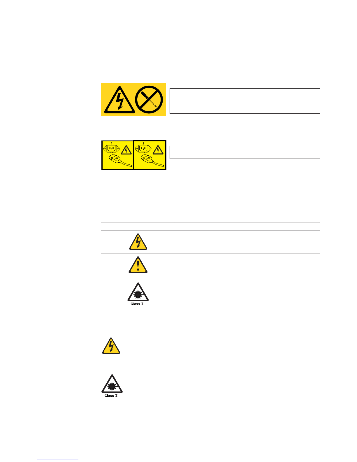
Caution notices
A caution notice calls attention to a situation that is potentially hazardous to people
because of some existing condition. A caution notice can be accompanied by
different symbols, as in the examples below:
If the symbol is... It means....
A hazardous electrical condition with less severity than
electrical danger.
A generally hazardous condition not represented by other
safety symbols.
A hazardous condition due to the use of a laser in the
product. Laser symbols are always accompanied by the
classification of the laser as defined by the U. S.
Department of Health and Human Services (for example,
Class I, Class II, and so forth).
Sample caution notices:
CAUTION:
This product is equipped with a 3–wire (two conductors and
ground) power cable and plug. Use this power cable with a properly
grounded electrical outlet to avoid electrical shock. (C018)
CAUTION:
Data processing environments can contain equipment transmitting
on system links with laser modules that operate at greater than
Class 1 power levels. For this reason, never look into the end of an
optical fiber cable or open receptacle. (C027)
Safety and environmental notices xi
Page 14

Attention notices
An attention notice indicates the possibility of damage to a program, device, or
system, or to data. An exclamation point symbol may accompany an attention
notice, but is not required. A sample attention notice follows:
Attention: Do not bend a fibre cable to a radius less than 5 cm (2 in.);
you can damage the cable. Tie wraps are not recommended for optical
cables because they can be easily overtightened, causing damage to the
cable.
Laser safety
This equipment contains Class 1 laser products, and complies with FDA radiation
Performance Standards, 21 CFR Subchapter J and the international laser safety
standard IEC 825-2.
CAUTION:
Data processing environments can contain equipment transmitting on
system links with laser modules that operate at greater than Class 1
power levels. For this reason, never look into the end of an optical fiber
cable or open receptacle. (C027)
Attention: In the United States, use only SFP or GBIC optical transceivers that
comply with the FDA radiation performance standards, 21 CFR Subchapter J.
Internationally, use only SFP or GBIC optical transceivers that comply with IEC
standard 825–1. Optical products that do not comply with these standards may
product light that is hazardous to the eyes.
Usage restrictions
The optical ports of the modules must be terminated with an optical connector or
with a dust plug.
xii SAN16B-2 Installation, Service, and User’s Guide
Page 15

Rack safety
Rack installation
DANGER
v
Always lower the leveling pads on the rack cabinet.
v Always install stabilizer brackets on the rack cabinet.
v To avoid hazardous conditions due to uneven mechanical
loading, always install the heaviest devices in the bottom of
the rack cabinet. Always install servers and optional devices
starting from the bottom of the rack cabinets.
v Rack-mounted devices are not to be used as a shelf or work
space. Do not place any object on top of rack-mounted
devices.
v Each rack cabinet might have more than one power cord. Be
sure to disconnect all power cords in the rack cabinet before
servicing any device in the rack cabinet.
v Connect all devices installed in a rack cabinet to power
devices installed in the same rack cabinet. Do not plug a
power cord from a device installed in one rack cabinet into a
power device installed in a different rack cabinet.
CAUTION:
v Do not install a unit in a rack where the internal rack ambient
temperatures will exceed the manufacturer’s recommended
ambient temperature for all your rack-mounted devices.
v Do not install a unit in a rack where the air flow is compromised.
Ensure that air flow is not blocked or reduced on any side, front,
or back of a unit used for air flow through the unit.
v Consideration should be given to the connection of the
equipment to the supply circuit so that overloading of the
circuits does not compromise the supply wiring or overcurrent
protection.
v To provide the correct power connection to a rack, refer to the
rating labels located on the equipment in the rack to determine
the total power requirement of the supply circuit.
v (For sliding drawers.) Do not pull out or install any drawer or
feature if the rack stabilizer brackets are not attached to the rack.
Do not pull out more than one drawer at a time. The rack may
become unstable if you pull out more than one drawer at a time.
v (For fixed drawers.) This drawer is a fixed drawer and should not
be moved for servicing unless specified by manufacturer.
Attempting to move the drawer partially or completely out of the
rack may cause the rack to become unstable or cause the drawer
to fall out of the rack.
(R001)
Safety and environmental notices xiii
Page 16

Rack relocation (19″ rack)
CAUTION:
Removing components from the upper positions in the rack cabinet improves
rack stability during relocation. Follow these general guidelines whenever you
relocate a populated rack cabinet within a room or building:
v Reduce the weight of the rack cabinet by removing equipment starting at
the top of the rack cabinet. When possible, restore the rack cabinet to the
configuration of the rack cabinet as you received it. If this configuration is
not known, you must do the following:
– Remove all devices in the 32U position and above.
– Ensure that the heaviest devices are installed in the bottom of the rack
cabinet.
– Ensure that there are no empty U-levels between devices installed in the
rack cabinet below the 32U level.
– If the rack cabinet you are relocating is part of a suite of rack cabinets,
detach the rack cabinet from the suite.
– Inspect the route that you plan to take when moving the rack to
eliminate potential hazards.
– Verify that the route that you choose can support the weight of the
loaded rack cabinet. Refer to the documentation that came with your
rack cabinet for the weight of a loaded rack cabinet.
– Verify that all door openings are at least 760 x 2030 mm (30 x 80 in.).
– Ensure that all devices, shelves, drawers, doors, and cables are secure.
– Ensure that the four leveling pads are raised to their highest position.
– Ensure that there is no stabilizer bracket installed on the rack cabinet
during movement.
– Do not use a ramp inclined at more than ten degrees.
– Once the rack cabinet is in the new location, do the following:
- Lower the four leveling pads.
- Install stabilizer brackets on the rack cabinet.
- If you removed any devices from the rack cabinet, repopulate the rack
cabinet from the lowest position to the highest position.
– If a long distance relocation is required, restore the rack cabinet to the
configuration of the rack cabinet as you received it. Pack the rack
cabinet in the original packaging material, or equivalent. Also, lower the
leveling pads to raise the casters off of the pallet and bolt the rack
cabinet to the pallet.
(R002)
xiv SAN16B-2 Installation, Service, and User’s Guide
Page 17

Environmental notices
Use the environmental statements and warning in this section to guide you when
using this product and in properly disposing of the product and its components.
Product recycling and disposal
This unit must be recycled or discarded according to applicable local and national
regulations. IBM encourages owners of information technology (IT) equipment to
responsibly recycle their equipment when it is no longer needed. IBM offers a
variety of product return programs and services in several countries to assist
equipment owners in recycling their IT products. Information on IBM product
recycling offerings can be found on IBM’s Internet site at
http://www.ibm.com/ibm/environment/products/prp.shtml
Note: This mark applies only to countries within the European Union (EU) and
Norway.
Appliances are labeled in accordance with European Directive 2002/96/EC
concerning waste electrical and electronic equipment (WEEE). The Directive
determines the framework for the return and recycling of used appliances as
applicable throughout the European Union. This label is applied to various products
to indicate that the product is not to be thrown away, but rather reclaimed upon end
of life per this Directive.
In accordance with the European WEEE Directive, electrical and electronic
equipment (EEE) is to be collected separately and to be reused, recycled, or
recovered at end of life. Users of EEE with the WEEE marking per Annex IV of the
WEEE Directive, as shown above, must not dispose of end of life EEE as unsorted
municipal waste, but use the collection framework available to customers for the
return, recycling and recovery of WEEE. Customer participation is important to
minimize any potential effects of EEE on the environment and human health due to
the potential presence of hazardous substances in EEE. For proper collection and
treatment, contact your local IBM representative.
Safety and environmental notices xv
Page 18

Battery return program
This product may contain sealed lead acid, nickel cadmium, nickel metal hydride,
lithium, or lithium ion battery. Consult your user manual or service manual for
specific battery information. The battery must be recycled or disposed of properly.
Recycling facilities may not be available in your area. For information on disposal of
batteries outside the United States, go to
http://www.ibm.com/ibm/environment/products/batteryrecycle.shtml or contact your
local waste disposal facility.
In the United States, IBM has established a return process for reuse, recycling, or
proper disposal of used IBM sealed lead acid, nickel cadmium, nickel metal hydride,
and other battery packs from IBM equipment. For information on proper disposal of
these batteries, contact IBM at 1-800-426-4333. Please have the IBM part number
listed on the battery available prior to your call.
For Taiwan:
Cable warning
WARNING: Handling the cord on this product or cords associated
with accessories sold with this product, will expose you to lead, a
chemical known to the State of California to cause cancer and birth
defects or other reproductive harm. Wash hands after handling.
xvi SAN16B-2 Installation, Service, and User’s Guide
Page 19

About this document
This document describes how to install, service, and use the IBM TotalStorage
®
SAN16B-2 SAN Switch (2005 Models B16 and 16B). Throughout this document, the
product is referred to as the SAN16B-2 , or simply the switch to apply to both
models. If information applies to only one model, the model will be specified as the
B16 or the 16B.
The sections that follow provide information about:
v “Who should read this document”
v “Product documents”
v “Brocade documents”
v “Getting help” on page xviii
v “How to send your comments” on page xviii
Who should read this document
This document is intended for clients who are responsible for installing, servicing,
and using the SAN16B-2 SAN switches.
Product documents
The following documents contain information related to this product:
v IBM TotalStorage SAN16B-2 Installation, Service, and User’s Guide, GC26-7753
(this document)
v IBM eServer Safety Notices, G229–9054
v IBM TotalStorage SAN b-type 2005 Statement of Limited Warranty, GC26–7654
Brocade documents
IBM b-type switches use software licensed from Brocade Communications Systems,
Inc. Yo u can find information related to the software that supports the director in the
following documents on the CD-ROM supplied with this product:
Brocade Fabric OS
v Brocade Fabric OS Administrator’s Guide
v Brocade Fabric OS Command Reference Manual
v Brocade Fabric OS MIB Reference Manual
v Brocade Fabric OS System Error Message Reference Manual
Brocade Fabric OS optional features
v Brocade Fabric Watch Administrator’s Guide
v Brocade Secure Fabric OS User’s Guide
v Brocade Web Tools Administrator’s Guide
IBM and Brocade product matrix
When you use any of the Brocade documents, you will notice that the model
numbers reflect the original Brocade switches. Table 1 on page xviii provides a
product matrix for you to use to correlate the Brocade model numbers to the IBM
product names and machine types and model numbers. Note that a number of
© Copyright IBM Corp. 2005 xvii
Page 20

these products are no longer marketed by IBM or Brocade.
Table 1. Brocade and IBM product and model number matrix
Brocade product
name
IBM TotalStorage product
name
IBM product and model
number
SilkWorm AP7420 SAN16B-R multiprotocol router 2109 Model A16
SilkWorm 200E SAN16B-2 2005 Models B16 and 16B
SilkWorm 3250 SAN Switch H08 2005 Model H08
SilkWorm 3800 SAN Switch F16 2109 Model F16
SilkWorm 3850 SAN Switch H16 2005 Model H16
SilkWorm 3900 SAN Switch F32 2109 Model F32
SilkWorm 4100 SAN32B-2 2005 Models B32 and 32B
SilkWorm 12000 SAN Switch M12 2109 Model M12
SilkWorm 24000 SAN Switch M14 2109 Model M14
SilkWorm 48000 SAN256B Director 2109 Model M48
Getting help
For the latest version of your product documentation, visit the web at
http://www.elink.ibmlink.ibm.com/public/applications/publications/cgibin/pbi.cgi.
For more information about IBM SAN products, see the following Web site:
http://www.ibm.com/servers/storage/san/
For support information for this product and other SAN products, see the following
Web site:
http://www.ibm.com/servers/storage/support/san
For detailed information about the Fibre Channel standards, see the Fibre Channel
Industry Association (FCIA) Web site at:
www.fibrechannel.org/
Visit www.ibm.com/contact for the contact information for your country or region.
You can also contact IBM within the United States at 1-800-IBMSERV
(1-800-426-7378). For support outside the United States, you can find the service
number at:
http://www.ibm.com/planetwide/.
How to send your comments
Your feedback is important in helping us provide the most accurate and high-quality
information. If you have comments or suggestions for improving this document,
send us your comments by e-mail to starpubs@us.ibm.com or use the Readers’
Comments form at the back of this publication. Be sure to include the following:
v Exact publication title
v Form number (for example, GC26-1234-02)
v Page numbers to which you are referring
If
the Reader Comment Form in the back of this manual is missing, you can direct
your mail to:
xviii SAN16B-2 Installation, Service, and User’s Guide
Page 21

International Business Machines Corporation
Information Development
Department GZW
9000 South Rita Road
Tucson, Arizona 85744-0001 U.S.A.
When you send information to IBM, you grant IBM a nonexclusive right to use or
distribute the information in any way it believes appropriate without incurring any
obligation to you.
About this document xix
Page 22

xx SAN16B-2 Installation, Service, and User’s Guide
Page 23

Chapter 1. Introducing the SAN16B-2 switch
The IBM TotalStorage SAN16B-2 fabric switch provides a 16–port addition to the
IBM TotalStorage SAN b-type 4 Gbps switch family. This family of products provide
enhancements to storage networking with improved affordability, higher throughput,
and increased port density.
The SAN16B-2 switch provides 4 gigabit throughput capability to small and
mid-range Storage Area Networks (SANs). The switch is a 1U Fibre Channel switch
which is scalable in 8–, 12–, and 16–port increments. The 16 non-blocking ports
provide full-duplex throughput at 1, 2, or 4 Gbps link speeds. This switch includes
Fabric OS 5.0, and features full compatibility with all existing IBM TotalStorage
b-SAN switch models. The switch can operate in a fabric containing multiple
switches, or operate independently.
This chapter provides the following information:
v “Features and functions of the SAN16B-2 switch”
v “Supported connectivity” on page 2
v “Switch characteristics” on page 2
v “Supported (optional) features” on page 3
Features and functions of the SAN16B-2 switch
The switch provides the following features and functions:
v 4 gigabit per second port-to-port throughput with auto-sensing capability for
connecting to existing 1-, 2-, and 4-gigabit host servers, storage, and switches
v 1U form factor for enhanced port density and space utilization
v 16 non-blocking ports with full-duplex throughput at 1–, 2–, or 4–Gbps link
speeds
v High availability features: automatic path routing, and nondisruptive firmware
upgrades
v Scalable ports on demand: 8–, 12–, or 16–port increments to accommodate a
broad range of connectivity solutions
v Support for 2– and 4–gigabit short wave and long wave small form-factor
pluggable (SFP) optical transceivers
v Open Fibre Channel Protocol (FCP) support
v Base firmware features: Web Tools and Advanced Zoning.
v Optional features:
– Additional Port Activation
– Fabric Watch
– Advanced Security
– Enhanced ISL Trunking
– Performance Monitoring
© Copyright IBM Corp. 2005 1
Page 24

Supported connectivity
Specific details on supported operating systems, servers, and devices, storage
products attachability, SAN connectivity products, and configuration options are
available at the following web site: http://www.ibm.com/totalstorage/san/b-type.
The switch supports Fibre Channel connectivity for the following:
Servers
v IBM eServer
™
pSeries
®
and selected RS/6000
®
servers
v IBM eServer iSeries
™
and selected AS/400
®
servers
v IBM eServer xSeries
®
and selected Netfinity
®
servers
v Other Intel-based servers with Linux
™
and Windows
®
2000 and Windows 2003
Server
v Selected Sun and HP servers
Storage
Systems
v IBM TotalStorage DS4000 Series
v IBM TotalStorage DS6000 Series
v IBM TotalStorage DS8000 Series
v IBM TotalStorage FAStT Family of Storage Servers
v IBM TotalStorage Enterprise Storage Server
®
(ESS)
v IBM TotalStorage SAN Volume Controller
v IBM TotalStorage 3580, 3588, 3590 and 3592 Tape Drives
v IBM TotalStorage 3494, 3582, 3583, and 3584 Tape Libraries
v IBM TotalStorage 3581 Tape Autoloader
v IBM TotalStorage 3584 High Availability Frame Model HA1
v Other selected storage systems
Switch characteristics
The following sections describe the physical characteristics of the switch.
Port side of the SAN16B-2 switch
Figure 1 on page 3 shows the port side of the switch. The serial port, Ethernet port,
and the Fibre Channel ports are all located on this side of the switch. All LEDs are
also located on the port side of the switch. These LEDs display the system status,
power status, port status, and port speed. See “Interpreting LED activity” on page
21 for a complete description of the locations and interpretations of these LEDs.
The switch enclosure has forced-air cooling, with the fans pushing the air from the
non-port side of the chassis through the enclosure, and exhausting through the
holes on the port side. Three dual speed fans provide the cooling for the switch.
2 SAN16B-2 Installation, Service, and User’s Guide
Page 25

1 AC power receptacle
2 Ethernet port
3 Serial port
4 Fibre Channel ports (16)
Non-port side of the SAN16B-2 switch
The non-port side of the switch is used solely for air flow and for serial number
labels. The three built-in fans are located on this side of the switch. These fans
cannot be removed or replaced.
Supported (optional) features
The switch supports the following optional software, which can be activated with the
purchase of the corresponding license key.
v “Additional Port Activation”
v “Full Fabric Activation”
v “Fabric Watch”
v “Advanced Security” on page 4
v “Performance Bundle (Performance Monitoring and ISL Trunking)” on page 4
Additional Port Activation
The base switch model provides the first eight ports (0 through 7) enabled.
Additional 4–port activation enables an upgrade to 12 and 16 ports. Customers can
optionally purchase port activation for ports eight to eleven (first four-port
increment), and ports twelve to fifteen (second four-port increment). Port activation
features do not include fiber optic transceivers.
Full Fabric Activation
Full Fabric Activation is required to enable E_Ports. The switch, by default, cannot
be connected to another switch until Full Fabric is installed. Without this license
activation, the switch can be directly connected to hosts and storage devices. Full
Fabric is a prerequisite to Advanced Security Activation and Performance Bundle
Activation.
Fabric Watch
Fabric Watch enables real-time proactive awareness of the health, performance,
and security of each switch and automatically alerts network managers to problems
in order to avoid costly failures. Fabric Watch includes the following functions:
v Real-time tracking of numerous fabric and switch elements
scale: 5/16" = 1"
!
IOIOI
0
4
3
7
152
6
8
12
11
15
91310
14
1
2
3
4
b1600007
Figure 1. Port side of the SANB16-2 switch
Chapter 1. Introducing the SAN16B-2 switch 3
Page 26

v Automatic event notifications when switch and fabric elements exceed thresholds
v Security, availability, and congestion monitoring thresholds and alerts
Advanced Security
Advanced Security Activation is designed to enables policy-based security
mechanisms integrated within Fabric Operating System V2.6, and later. To enable
advanced security capabilities, all switches within the IBM SAN Switch Fabric must
be configured with their respective Fabric operating system version (2.6 or later)
before activating the Advanced Security feature license key. When activated across
the IBM SAN Switch Fabric, the Advanced Security Activation feature supports the
following security capabilities:
v Centralized security management (trusted switches)
v Fabric-wide security policies to control access
v Port-level access control
v Switch-level access control
v Management access controls (Telnet, SNMP, HTTP, API)
v Encryption of management data such as passwords
v Strong and non-reputable authentication between switches
Performance Bundle (Performance Monitoring and ISL Trunking)
Performance Bundle Activation is a plant order only feature consisting of both
Enhanced Inter-Switch Link (ISL) Trunking and Performance Monitoring capabilities.
Activation of either feature can be ordered separately for field installation.
Performance Monitoring helps identify end-to-end bandwidth usage by host/target
pairs and is designed to provide information for capacity planning. Trunking enables
Fibre Channel packets to be efficiently distributed across multiple Inter-Switch
connections (links) between two SAN b-type fabric switches, while preserving
in-order delivery. Both SAN b-type fabric switches must have ISL Trunking
activated.
ISL Trunking
Enhanced ISL Trunking is supported between two SAN16B-2, SAN32B-2, or
SAN256B 4-Gbps models and enables Fibre Channel packets to be distributed
across up to eight 4 Gbps-capable ISLs for a combined bandwidth of up to 32
Gbps. When connecting the 4 Gbps-capable switches to earlier 2-Gbps b-type
fabric switch models, ISL Trunking is supported with link speeds operational at 2
Gbps and Fibre Channel packets distributed across up to four ISLs for a combined
bandwidth of up to 8 Gbps.
If your switch is licensed for ISL Trunking, use the trunking groups available on the
switch. For the SAN16B-2, the maximum number of ports per trunk is four. The
Fibre Channel ports are numbered from left to right, color-coded into groups of four
to indicate the groups of ports that can be used in the same interswitch link (ISL)
trunking group. The number of trunked lines can be from two through four ports
within a single trunk group. The trunk groups are shown in Figure 2 on page 5.
4 SAN16B-2 Installation, Service, and User’s Guide
Page 27

Trunking group Port numers
Group 1 Ports 0–3
Group 2 Ports 4–7
Group 3 Ports 8–11
Group 4 Ports 12–15
Note: For more information about trunking, refer to the Brocade Fabric OS
Administrator’s Guide.
0
4
3
7
152
6
8
12
11
15
91310
14
Trunking Group 1
Trunking Group 2
Trunking Group 3
Trunking Group 4
h1600002
Figure 2. Trunking groups
Chapter 1. Introducing the SAN16B-2 switch 5
Page 28

6 SAN16B-2 Installation, Service, and User’s Guide
Page 29

Chapter 2. Installing and configuring the SAN16B-2
You can install the SAN16B-2 in either of two ways:
v As a stand-alone unit on a flat surface
v In an Electronic Industries Association (EIA) cabinet using a slide-rail rack mount
kit, which is provided with the switch. When you mount the switch into a slide-rail
rack, you can mount the chassis to slide from either the port side or the non-port
side.
This
chapter provides the following information:
v “Items included with the switch”
v “Installation and safety considerations” on page 8
v “Installing a stand-alone SAN16B-2” on page 9
v “Installing a SAN16B-2 into an EIA cabinet” on page 10
v “Cabling and configuring the SAN16B-2” on page 16
Items included with the switch
The following items are included with the standard shipment of the switch . When
you open the packaging, verify that these items are included in the package and
that no damage occurred during shipping.
v One SAN16B-2 switch
v An accessory kit that contains the following items:
– One grounded 1.8 m (6 ft) country-specific power cables
– One RS–232 serial cable (with removable adapter for converting to an RJ-45
connector)
– Four rubber mounting feet, required for setting up the switch as a stand-alone
unit
– One slide-rail rack mount kit, with instructions
– SFP transceivers (quantity depending upon features ordered)
– SAN16B-2 Installation, Service, and User’s Guide (this document).
– IBM documentation CD
© Copyright IBM Corp. 2005 7
Page 30

Installation and safety considerations
Use this section to prepare your site for a safe and successful installation.
Attention: Although the switch has been designed for customer installation and
replacement procedures, you must first ensure that the rack into which the switch is
to be installed is also customer accessible. If it is not, then only trained personnel
can install and service these switches in such a rack.
Attention: Read the “Safety and environmental notices” on page ix
before attempting any installation or maintenance procedures.
Facility requirements
To ensure correct operation of the switch, the facility where the switch is in use
must meet the requirements listed in Table 2.
Table 2. Facility requirements
Type Requirements
Thermal
v A minimum air flow of 40.1 cubic meters
per hour (24 cubic feet per minute)
available in the immediate vicinity of the
switch
v Ambient air temperature not exceeding
40°C (104°F) while the switch is operating
Cabinet (when rack-mounted)
v A minimum of one EIA unit (4.45 cm; 1.75
inches) high in a 19-in. (48.3 cm.) cabinet
, and at least 30 inches (76.2 cm) deep.
v Ground all equipment in the cabinet
through a reliable branch circuit
connection and maintain ground at all
times. Do not rely on a secondary
connection to a branch circuit, such as a
power strip.
v Ensure that airflow and temperature
requirements are met on an ongoing
basis, particularly if the switch is installed
in a closed or multicabinet assembly.
v Verify that the additional weight of the
switch does not exceed the cabinet's
weight limits or unbalance the cabinet in
any way.
v Cabinet must be secured to insure stability
in case of unexpected movement, such as
an earthquake
8 SAN16B-2 Installation, Service, and User’s Guide
Page 31

Electrical requirements
For successful installation and operation of the switch, ensure that the following
electrical requirements are met.
v Primary ac input 100-240 V ac (the switch autosenses input voltage)
v Correctly wired primary outlet, with circuit protected by a circuit breaker and
grounded in accordance with local electrical codes
v Adequate supply circuit, line fusing, and wire size, as specified by the electrical
rating on the switch nameplate
Environmental requirements and considerations
To ensure proper operation, the switch must not be subjected to environmental
conditions beyond those for which it was tested. The ranges specified in Table 3 list
the acceptable environment for both operating and non-operating conditions.
Table 3. Environmental requirements
Condition Acceptable range during operation Acceptable range during
non-operation
Temperature -10° to + 40° C (14° to 104° F) -50° to 100° C (-22° to 212° F)
Humidity 20% to 85% RH non-condensing, at 40°
C (104° F), with maximum gradient of
10% per hour
10% to 85% RH
non-condensing, at 70° C (158°
F)
Altitude 0 to 3,000 m (9,800 ft) above sea level 0 to 12 km (39,370 ft) above sea
level
Shock 20 G, 6 ms duration, half-sine wave 15 G, 12–18 ms duration,
trapezoid
Vibration 0.5 G, 5–500 Hz 2.0 G, 5–500 Hz
Air flow 40.1 cubic meters per hour (24 cubic feet
per minute)
None required
Installing a stand-alone SAN16B-2
To install the switch as a stand-alone unit, use the following procedure:
1. Unpack the switch and verify that all items listed in “Items included with the
switch” on page 7 are present and undamaged.
Note:
If any items are damaged or missing, contact the IBM Quality Hotline
toll-free at 1-800-442-6773 within the United States and Canada, or
direct dial 770-858-8459 in other locations.
2. Clean the four corner depressions on the bottom of the switch enclosure, place
an adhesive rubber foot in each one, and firmly press into place. Applying the
rubber feet onto the switch helps prevent the switch from sliding off the
supporting surface.
3. Place the switch on a flat, sturdy surface.
4. Provide power to the switch as described in “Powering up the switch and
logging in” on page 18.
Attention: Do not connect the switch to the network until the IP address is
correctly set. For instructions on how to cable and configure the switch, and how to
set the IP address, see “Cabling and configuring the SAN16B-2” on page 16.
Chapter 2. Installing and configuring the SAN16B-2 9
Page 32

Installing a SAN16B-2 into an EIA cabinet
Attention: Refer to “Rack safety” on page xiii for danger and caution notices
related to rack and cabinet installations.
You can install the rack mount kit in either of two ways:
v To allow the port side of the switch to slide out of the exhaust-air side of the
cabinet. In this installation, the port side of the switch is flush with the edge of the
cabinet.
v To allow the non-port side of the switch to slide out the cool-air side of the
cabinet. In this installation, the port side of the switch is set 3 in. (7.62 cm.) back
from the edge of the cabinet, allowing a more gradual bend in the fiber optic
cables.
Time required
Approximately 30 minutes
Items required
You need the following items to install the switch in a slide-rail rack:
v Straight slot screwdriver
v Rack space: 1.5 EIA units of rack space, 48.26 cm (19 in.) wide, and 60.96 cm
(24 in.) deep
v Two power cables that are provided with the switch
v Two power outlets
v Rack mount kit
Attention: Use the exact screws specified in the procedure for use with the
switch chassis. Using screws longer than 3/16 in. can damage the switch. The
different types of screws are listed in Table 4 on page 11.
Note:
Make sure that you tighten all screws used in this procedure.
Installation instructions
To install the switch in a slide-rail rack that meets EIA standards, use the following
procedure.
Note: These procedures use parts that are included in the rack-mount kit. These
parts are listed in Table 4 on page 11. The installation procedure
cross-references the items in this table. Be sure to use the referenced parts
when you perform each step.
Before you start the rack-mount installation process, locate the rack-mount slides
and the mounting bracket that are provided in the shipping container.
Figure 3 on page 11 shows the rack assembly. The number keys, such as 1, refer
to the items listed in Table 4 on page 11.
10 SAN16B-2 Installation, Service, and User’s Guide
Page 33

1. Unpack the rack-mount kit and verify that all ordered items and parts are
present and undamaged. See Table 4 for a list of parts and the quantities
supplied.
Table 4. Parts supplied with the rack-mount kit
Item Description Quantity
1 Rack mount slide (inner and outer slide) 2
2 Right rack mount bracket (optional bracket for
front of switch)
1
3 Left rack mount bracket (optional bracket for
front of switch)
1
4 Rack mounting bracket (3-hole) 4
5 Nut clip, M5 11
6 Screw, 8-32 x 3/16 in., zinc 11
7 Screw, M5 x 12 11
8 Bracket to slide rack kit (contains items 9 -
12)
1
9 Screw, 8-32 x 3/8 in., zinc 5
10 Washer, flat, No. 8 5
11 Washer, lock, No. 8 5
12 Nut, hex, 8-32 5
SJ000153
Outer Slide
EIA Rack Rail
Inner Slide
Front of Switch
See
Detail A
4
4X
9
8X
1
2X
7
4X
6
2X
Detail A
10
8X
11
8X
12
8X
2
7
2X
6
5X
7
4X
4X
5
3
Figure 3. Rack assembly
Chapter 2. Installing and configuring the SAN16B-2 11
Page 34

2. Separate the inner and outer slides.
a. Open one of the slides until the lock engages.
b. Press the lock release lever (1 in Figure 4) and remove the inner rail from
the outer rail.
c. Repeat step 2a and step 2b for the other rail.
Note: For racks with flush-mount doors, such as the 9306 Netfinity racks, do
not install the ears. Instead, use the rack-mount slides by attaching the
switch to the set of mounting holes, which are offset 3 inches into the
rack.
3. Install the inner (smaller) slide on the switch chassis, as Figure 3 on page 11
shows.
Attention: If you use screws longer than 3/16 in., you can damage the switch.
a. Position the flat side of the inner rail along one side of the switch. Align the
holes in the rail with the threaded holes in the side of the switch chassis.
The chamfered end of the inner rail should face toward the rear of the
switch (away from the ports) as shown in Figure 5 on page 13.
b. Attach the inner rail by using three of the 8-32 x 3/16 in. zinc screws (6 in
Table 4 on page 11).
SJ000046
1
Figure 4. Separating the inner and outer rails.
12 SAN16B-2 Installation, Service, and User’s Guide
Page 35

c. Repeat step 3a on page 12 and step 3b on page 12 for the second inner rail
on the other side of the switch chassis.
4.
Optional step: If desired, install the right rack mount bracket 2 (see Figure 3
on page 11) and the left rack mount bracket 3 on the switch chassis. Use
these brackets to secure the switch to the rack as shown in Figure 5.
Attention: Do not use screws longer than 3/16 in.; they can damage the
switch.
a. Position the left rack mount bracket at the left front corner of the switch
chassis. Align the two holes in the bracket with the two threaded holes in the
switch chassis.
b. Attach the bracket by using two of the 8-32 x 3/16 in. zinc screws (see 6
in Figure 3 on page 11)
c. Repeat step 4a and step 4b for the right rack mount bracket on the right
front corner of the switch chassis.
5.
Attach all four of the 3-hole rack mounting brackets 4 in Figure 6 on page 14.
a. Position a 3-hole rack mounting bracket 4 at the end of one of the outer
slides.
b. Attach the bracket by using the 8-32 x 3/8 in. zinc screws 9. Ensure that
the screw heads are inside the slides.
c. Place one each of the following items on the outer end of the screw in the
order listed:
1) Washer, flat No. 8 10
2) Washer, lock No. 8 11
3) Nut, hex, 8-32 12
d. Repeat steps 5a through 5c for the three remaining rail ends.
SJ000047
Front
1
6
3
Figure 5. Mounting the moving portion of the slide and mounting brackets to the switch
Chapter 2. Installing and configuring the SAN16B-2 13
Page 36

6. Install the outer (larger) slides in the rack, as shown in Figure 6.
a. At the desired height, install the five M5 nut clips 5. Put three M5 nut clips
in the front of the rack and two in the back. The middle clip in the front of
the rack is for the locking ears.
Note:
Some rack mount kits might use 10-32 nut clips in place of the M5
nut clips for the locking ears.
b. Attach the slides by using four M5 x 12 screws 7 (see Figure 3 on page
11).
c. Repeat step 6a and step 6b for the other rail.
7.
Install the switch in the rack.
a. Position the switch in front of the rack. Insert the switch into the rack by
sliding the inner slides that are mounted on the switch into the outer slides
that are mounted on the rack. See Figure 7 on page 15.
SJ000048
3
9
11
12
10
5
4
4
1
Figure 6. Mounting the fixed portion of the rail and the locking ears to the rack
14 SAN16B-2 Installation, Service, and User’s Guide
Page 37

b. Check the alignment of the slides by sliding the switch in and out of the
rack. Any difficulty moving the switch indicates lateral stress or
misalignment. If this situation occurs, adjust the slide positions until the
movement is smooth.
8. Optional step: If the right and left rack mount brackets are installed on the front
corners of the switch, attach both brackets to the cabinet rack by using M5 x 12
screws 7. See step 4 on page 13 and Figure 3 on page 11. The screws
should pass through the front of each bracket and the slide rail.
Note:
Some rack mount kits might use 10-32 nut clips in place of the M5 nut
clips for the locking ears.
9. Continue with initial setup of the switch by following the procedures in “Cabling
and configuring the SAN16B-2” on page 16.
DANGER
An
electrical outlet that is not correctly wired could place
hazardous voltage on metal parts of the system or the devices
that attach to the system. It is the responsibility of the customer
to ensure that the outlet is correctly wired and grounded to
prevent an electrical shock. (D004)
Note: Do not connect the switch to the network until you perform one of the
following steps:
v Set the internet protocol (IP) address.
v Verify that the default IP address does not conflict with the existing IP
addresses in the same network.
SJ000049
Figure 7. Inserting slides into the rack rails
Chapter 2. Installing and configuring the SAN16B-2 15
Page 38

Cabling and configuring the SAN16B-2
You must configure the switch to ensure correct operation within a network and
fabric. For instructions about how to configure the switch to operate in a fabric that
contains switches from other vendors, refer to the Brocade Fabric OS
Administrator’s Guide.
For more information about the commands used in this procedure, refer to the
Brocade Fabric OS Command Reference Manual.
Recommendations for cable management
Attention: The minimum bend radius for a 50 micron cable is 51 mm (2 in.) under
full tensile load and 30.5 mm (1.2 in.) with no tensile load. Because they are easily
overtightened, tie wraps are not recommended for optical cables.
Cables can be organized and managed in a variety of ways: for example, using
cable channels on the sides of the cabinet or patch panels to minimize cable
management. A list of recommendations follows:
v Plan for rack space required for cable management before installing the switch.
v Leave at least 1 meter (3.28 ft) of slack for each port cable. This provides room
to remove and replace the switch, allows for inadvertent movement of the rack,
and helps prevent the cables from being bent to less than the minimum bend
radius.
v If you are using ISL Trunking, consider grouping cables by trunking groups. The
cables used in trunking groups must meet specific requirements, as described in
the Brocade Fabric OS Administrator’s Guide.
v For easier maintenance, label the fiber optic cables and record the devices to
which they are connected.
v Keep LEDs visible by routing port cables and other cables away from the LEDs.
v Use Velcro straps to secure and organize fibre optic cables. Do not use tie wraps
on fiber optic cables, because wraps are easily overtightened and can damage
the optic fibers.
Items required for installation
The following items are required for configuring and connecting the switch for use in
a network and fabric:
v SAN16B-2 switch installed and connected to a power source
v Workstation with an installed terminal emulator, such as HyperTerminal
v Available IP address and corresponding subnet mask and gateway address
v Serial cable (provided)
v Ethernet cable
v SFP transceivers and compatible fibre cables, as required
v Access to an FTP server for backing up the switch configuration (optional)
Configuring the SAN16B-2
Follow the steps described in the next sections to configure your switch.
1. “Creating a serial connection” on page 17
2. “Powering up the switch and logging in” on page 18
3. “Setting the IP address” on page 18
16 SAN16B-2 Installation, Service, and User’s Guide
Page 39

4. “Creating an Ethernet connection and logging in” on page 19
5. “Modifying the domain ID (optional)” on page 19
6. “Installing the SFP transceivers” on page 19
7. “Connecting the cables” on page 20
Creating a serial connection
Before you can begin configuring the switch, you must create a connection by way
of the serial port. To create a serial connection to the switch, perform the following
steps:
1. Using the provided serial cable, connect a workstation to the serial port on the
switch. (see 2 in Figure 8)
2. Disable any serial communication programs running on the workstation.
3. Open a terminal emulator application (such as HyperTerminal on a PC or TERM
in a UNIX
®
environment) and configure the application as follows:
v In a Windows 95, 98, 2000, or NT environment:
Bits per second 9600
Databits 8
Parity None
Stop bits 1
Flow control None
v
In a UNIX environment, type the following string at the prompt:
tip /dev/ttyb -9600
scale: 5/1 6" = 1"
!
IOIOI
0
4
3
7
152
6
8
12
11
15
91310
14
0
4
1
5
IOIOI
!
2
6
3
7
1
2
3
4
5
6
7
8
9
10
11
b1600008
Figure 8. SAN16B-2 port side details
Chapter 2. Installing and configuring the SAN16B-2 17
Page 40

Powering up the switch and logging in
After you create the serial connection using the steps in “Creating a serial
connection” on page 17, provide power to the switch by completing the steps below.
Note: Power is supplied to the switch as soon as the power supply is connected to
a power source, you should then see POST messages.
1. Connect the power cord to the power supply and the power source.
Attention: Ensure that the power cable is routed so that it is not pinched or
exposed to stress when the switch is moved on the slide-rails. Ensure that the
cord has a minimum service loop of six inches available at the connection to the
switch.
The power supply LED (8 in Figure 8 on page 17) lights up green, and the
switch begins running a Power On Self-Test (POST). The POST should
complete and the switch will complete the boot process in about three minutes.
2. After POST is complete, verify that the System Status 9 and Power Status
8 LEDs are green (see “Interpreting LED activity” on page 21 for more
details).
3. Using a serial connection, when the terminal emulator application stops
reporting information, press Enter to display the login prompt.
4. Log in using the administrative account. The logon is admin and the default
password is password. You can create up to two simultaneous admin sessions
and four user sessions. For details, refer to the Brocade Fabric OS
Administrator’s Guide and the Brocade Fabric OS Command Reference Manual.
You will be prompted to change the default passwords on the switch during
initial login; you can bypass this by pressing Ctrl-C.
Setting the IP address
Replace the default IP address and related information with the information
provided by your network administrator. By default, the IP address is set to
10.77.77.77.
1. Type ipAddrSet at the terminal emulator application prompt, as shown in the
following example.
2. Enter the requested information as prompted. In this example, the items in bold
are the new values that were entered.
Table 5. Example of changing an IP address
switch:admin> ipAddrSet
Ethernet IP Address [192.168.1.1]:10.32.53.47
Ethernet Subnetmask [255.255.255.0]:255.255.240.0
Fibre Channel IP Address [0.0.0.0]:
Fibre Channel Subnetmask [0.0.0.0]:
Gateway IP Address [0.0.0.0]:10.32.48.1
Set IP address now? [y = set now, n = next reboot]:y
IP address being changed...
Committing configuration...Done.
switch:admin>
3. Optionally, verify that the address was correctly set by entering the ipaddrShow
command at the prompt.
4. Record the IP address on the label on the port side of the chassis.
5. If the serial port is no longer required, log out of the serial console, remove the
serial cable, and replace the plug in the serial port.
18 SAN16B-2 Installation, Service, and User’s Guide
Page 41

Note: Any time the serial port is not in use, install the protective plug to keep
foreign material out of the port.
Creating an Ethernet connection and logging in
Create an Ethernet connection to the switch by performing the following steps:
1. Connect an Ethernet cable to the Ethernet port (1 in Figure 8 on page 17) and
to the workstation or to an Ethernet network that contains the workstation. After
this connection is made, the switch can be accessed remotely by command line
or by using Advanced Web Tools. Ensure that the switch is not being modified
from any other connections during the remaining steps.
2. Log in to the switch with Telnet using the admin account.
Modifying the domain ID (optional)
If desired, you can modify the domain ID. The default domain ID is domain 1. If the
switch is not powered on until after it is connected to the fabric and the default
domain ID is already in use, the domain ID for the new switch is automatically reset
to a unique value. If the switch is connected to the fabric after it has been powered
on and the default domain ID is already in use, Principal Switch in the fabric detects
the attempt to use a previously allocated domain ID and segments the ISL to that
switch. The fabric is otherwise unaffected and continues to operate normally.
To find the domain IDs that are currently in use, run the fabricShow command on
another switch in the fabric.
Note: The SAN16B-2 is an entry-level switch and should not be included in fabrics
with more than 10 domains.
To modify the domain ID, perform the following steps:
1. Disable the switch by entering switchDisable.
2. Enter configure. Enter a new value or press Enter to accept each default
value.
3. At the Fabric Parameters prompt, enter y and press Enter, as the following
example shows:
Fabric parameters (yes, y, no, n): [no] y
4. Enter a unique domain ID, such as the domain ID used by the previous switch,
if still available, as the following example shows:
Domain: (1..239) [1] 3
5. Complete the remaining prompts or press Ctrl+D to accept the remaining
default settings without going through each prompt.
6. Re-enable the switch by entering the switchEnable command.
Installing the SFP transceivers
If your switch came without SFP transceivers installed, or if the transceivers have
been removed, use the following procedure to install them into the Fibre Channel
ports. See “Installing an SFP” on page 29 for more detailed instructions.
The ports selected for use in trunking groups must meet specific requirements. For
a list of these requirements, refer to the Brocade Fabric OS Administrator’s Guide.
To install SFP transceivers, perform the following steps:
1. Remove the protective plugs from the ports to be used.
Chapter 2. Installing and configuring the SAN16B-2 19
Page 42

2. Position a transceiver so that it is oriented correctly and insert it into a port until
the latching mechanism clicks. The transceivers are keyed to ensure correct
orientation. If a transceiver does not install easily, ensure that it is correctly
oriented.
3. Repeat for the remaining ports, as required.
Connecting the cables
See “Installing fiber-optic cables” on page 31 for more detailed instructions with
illustrations.
Attention: The minimum bend radius for a 50-micron cable is 2 inches under full
tensile load, and 1.2 inches with no tensile load. Because they are easily
overtightened, tie wraps are not recommended for optical cables.
Connect the cables to the transceivers:
1. Remove the plugs from the end of the cable and from the SFP.
2. The cable connectors are keyed to ensure correct orientation. Orient a cable
connector so that the key (ridge on one side of connector) aligns with the slot in
the transceiver and insert cable into transceiver until latching mechanism clicks.
If a cable does not install easily, ensure it is correctly oriented. For instructions
specific to cable type, refer to the cable manufacturer's documentation.
3. Repeat for the remaining cables and transceivers, as required.
The
cables used in trunking groups must meet specific requirements. For a list of
these requirements, refer to the Brocade Fabric OS Administrator’s Guide.
Verifying the configuration
After you complete the configuration, use the LEDs and commands to verify that the
configuration has been accepted:
1. Check the LEDs to verify that all components are functional. For information
about LED patterns, refer to “Interpreting LED activity” on page 21.
2. Verify the correct operation of the switch by entering the switchShow command
from the workstation. This command provides information about the switch and
port status.
3. Verify the correct operation of the switch in the fabric by entering the
fabricShow command from the workstation. This command provides general
information about the fabric.
Backing up the configuration
Back up regularly to ensure that a recent configuration is available for downloading
to a replacement switch, if required. For specific instructions about how to back up
the configuration, refer to the Brocade Fabric OS Administrator’s Guide.
Back up the switch configuration to an FTP server by entering the configUpload
command and following the prompts. This command uploads the switch
configuration to the server, making it available for downloading to a replacement
switch, if necessary.
20 SAN16B-2 Installation, Service, and User’s Guide
Page 43

Chapter 3. Operating the SAN16B-2
This chapter provides the following information:
v “Powering the SAN16B-2 on and off”
v “Interpreting LED activity”
v “POST and boot specifications” on page 25
v “Interpreting POST results” on page 26
Powering the SAN16B-2 on and off
See Chapter 2, “Installing and configuring the SAN16B-2,” on page 7 for initial setup
instructions before powering the switch on for the first time. Once the switch has
been properly configured, follow these instructions to power the switch on and off at
other times.
To power on the switch, connect the power cable to the ac receptacle on the switch
and to a power source. The switch runs POST by default each time it is powered
on, reset, or rebooted, and requires a minimum of 3 minutes to run. To end the flow
of power to the switch, remove the power cord from the power source.
Interpreting LED activity
System activity and status can be determined through the activity of the LEDs on
the switch. All the switch’s LEDs are located on the port side of the switch.
There are three possible LED states: no light, a steady light, and a flashing light.
The steady lights and flashing lights can be green or amber.
Sometimes the LEDs flash either of these colors during boot, POST, or other
diagnostic tests. This is normal and does not indicate a problem unless all boot
processes and diagnostic tests are complete, and the LEDs continue to indicate a
problem status.
LED location
The LEDs are located on the port side of the switch (see Figure 9 on page 22).
They include:
v Power Status 8 (green only) to indicate a valid power supply to the system
v System Status 9 (green/amber) to indicate the current system status
v Ethernet Link 11 to indicate an active Ethernet connection
v Ethernet Speed 10 to indicate the Ethernet speed
v Port Status 7 (green/amber), located in pairs below each pair of Fibre Channel
ports (left LED of each pair)
v Port Speed 6 (green/amber), located in pairs below each pair of Fibre Channel
ports (right LED of each pair)
Note:
The pairs of port LEDs for all 16 ports are arrayed below the lower row of
ports. The pairs of port LEDs are located in the array in the same relative
positions as the ports. The port number of the associated Fibre Channel port
appears between the Port Status and Port Speed LEDs.
© Copyright IBM Corp. 2005 21
Page 44

Figure 9 shows the location of the LEDs on the port side of the switch. See “LED
patterns and recommended actions” for details about how to interpret the activity of
these LEDs, and possible actions to take.
1 Ethernet port 7 Port status LEDs (16
total)
2 Serial port 8 Power status LED
3 Fibre Channel ports
(16 total)
9 System status LED
4 LEDs for top row of
ports
10 Ethernet speed LED
5 LEDs for lower row of
ports
11 Ethernet link LED
6 Port speed LEDs (16
total)
LED patterns and recommended actions
Table 6 on page 23, Table 7 on page 24, and Table 8 on page 25 summarize LED
location, color, and meaning of the LEDs on the switch, as well as any
recommended user responses.
System and power LED patterns
The system and power LED patterns are shown in Table 6 on page 23.
scale: 5/1 6" = 1"
!
IOIOI
0
4
3
7
152
6
8
12
11
15
91310
14
0
4
1
5
IOIOI
!
2
6
3
7
1
2
3
4
5
6
7
8
9
10
11
b1600008
Figure 9. LEDs on the port side of the SAN16B-2
22 SAN16B-2 Installation, Service, and User’s Guide
Page 45

Table 6. System LED patterns during normal operation
LED name LED color Status of Hardware Recommended action
Power Status No light Switch is off or power supply has
failed.
Verify that the system is on and has
completed booting. If the system is
on, the unit is faulty. Contact IBM
Support.
Steady green Switch is on and power supply is
functioning properly
No action required.
System Status No light Switch is off , boot is not complete,
or boot failed.
Verify that the system is on and has
completed booting.
Steady green Switch is operational No action required.
Slow-flashing
green
(on 1 second, off
1 second)
One or both of the following are true:
v One or more environmental
ranges are exceeded.
v Error log contains one or more
port diagnostic error messages.
Complete the following steps:
1. Check environmental conditions,
error log, Port Status LEDs, SFPs,
cables, and loopback plugs.
2. Correct error condition
3. Clear error log.
4. Rerun diagnostics to verify fix.
5. Contact IBM Support if unable to
resolve.
Amber Switch is faulty, or is initializing. Wait a few moments to verify that the
switch is not initializing. Contact IBM
Support, if required.
Chapter 3. Operating the SAN16B-2 23
Page 46

Port LED patterns
Each port has two LEDs: a port speed and a port status indicator. These LEDs are
located below both rows of ports, and each set is labeled with the port number.
Table 7 shows the LED location, color, and meaning for these port LEDs.
Table 7. Port LED patterns during normal operation
LED name LED color Status of hardware Recommended action
Port Status No light No light or signal carrier (SFP or
cable) detected.
Check SFP and cable.
Steady green Port is online (connected to external
device) but has no traffic.
No action required.
Slow-flashing
green (on one
second, off one
second)
Port is online but segmented,
indicating a loopback cable or
incompatible switch.
Verify that the correct device is
connected to port and that the switch
and port settings are correct.
Fast-flashing
green (on 1/4
second, off 1/4
second)
Port is in internal loopback
(diagnostic).
No action required.
Flickering green Port is online with traffic flowing
through port.
No action required.
Steady amber Port is receiving light or signal carrier
but is not yet online.
No action required.
Slow-flashing
amber (on one
second, off one
second)
Port is disabled as the result of
diagnostics or portDisable command.
If all ports are slow-flashing amber,
the switch could be disabled.
Enable the port using the portEnable
command. See the Brocade Fabric
OS Command Reference Manual for
more information.
If all ports are slow-flashing amber,
enable the switch using the
switchEnable command.
Fast-flashing
amber (on 1/4
second, off 1/4
second)
Port is faulty. Perform the following steps:
1. Check the Port Status LEDs, error
log, SFP, and cable or loopback
plug.
2. Clear the error log.
3. Rerun the diagnostics to verify
that the error condition is fixed.
Alternating green
and amber
Port is bypassed. Check configuration of Fibre Channel
loop.
Port Speed Green on, amber
off
Port is transmitting/receiving at 2
Gb/sec.
No action required.
Green off, amber
off
Port is transmitting/receiving at 1
Gb/sec.
No action required.
Amber on, green
off
Port is transmitting/receiving at 4
Gb/sec.
No action required.
Ethernet LED patterns
Each Ethernet port has two LEDs, the Link LED, and the Speed LED (see Figure 9
on page 22 for the Ethernet port and Ethernet LED locations). Table 8 on page 25
describes the location, color, and meaning for the Ethernet LED activity.
24 SAN16B-2 Installation, Service, and User’s Guide
Page 47

Table 8. Ethernet LED patterns
LED name, location LED color Status of hardware Recommended action
Ethernet link Amber Link is valid. No action required.
Blinking amber Traffic.
Ethernet Speed No light Port speed is 10 Mb/sec No action required.
Steady green Port speed is 100 Mb/sec.
POST and boot specifications
When the switch is turned on (plugged in) or rebooted, the switch performs POST.
Total boot time with POST is a minimum of 3 minutes.
POST can be omitted after subsequent reboots by using the fastboot command or
entering the diagDisablePost command to persistently disable POST. For more
information about these commands, refer to the Brocade Fabric OS Command
Reference Manual.
POST
The success/failure results of the diagnostic tests that run during POST can be
monitored through the error log or the command line interface.
POST includes the following steps:
1. Preliminary POST diagnostics are run.
2. Operating system is initialized.
3. Hardware is initialized.
4. Diagnostic tests are run on several functions, including circuitry, port
functionality, memory, statistics counters, and serialization.
Boot
Boot completes in a minimum of 3 minutes if POST is run. In addition to POST,
boot includes the following steps after POST is complete:
1. Universal port configuration is performed.
2. Links are initialized.
3. Fabric is analyzed, and if any ports are connected to other switches, the switch
participates in a fabric configuration.
4. Switch obtains a domain ID and assigns port addresses.
5. Unicast routing tables are constructed.
6. Normal port operation is enabled.
Chapter 3. Operating the SAN16B-2 25
Page 48

Interpreting POST results
POST is a system check that is performed each time the switch is powered on,
rebooted, or reset. During POST, the LEDs flash amber and green. Any errors that
occur during POST are listed in the error log.
To determine whether POST completed successfully and whether or not any errors
were detected:
1. Verify that the switch LEDs indicate that all components are healthy. See the
tables in “LED patterns and recommended actions” on page 22 for descriptions
and interpretation of LED patterns. If one or more LEDs do not display a healthy
state, verify that the LEDs on the switch are not set to beacon; use the
switchShow command.
2. Verify that the switch prompt displays on the terminal of a computer workstation
connected to the switch. If there is no switch prompt when POST completes,
press Enter. If the switch prompt still does not display, open another Telnet
session or access the switch through another management tool. If this is not
successful, the switch did not successfully complete POST. Contact IBM Service
for repair.
3. Review the switch system log for errors. Any errors detected during POST are
written to the system log, which is accessible through the errShow command.
For
information about all referenced commands, and on accessing the error log,
refer to Brocade Fabric Administrator’s Guide. For information about error
messages, refer to the Brocade Fabric OS System Error Message Reference
Manual.
26 SAN16B-2 Installation, Service, and User’s Guide
Page 49

Chapter 4. Monitoring and maintaining the SANB16-2
Once the SANB16-2 is installed and configured, it does not require any regular
physical maintenance. You can monitor the health of the fabric as well as maintain
the health of the switch by using the information in this chapter.
v “Management features of the SANB16-2”
v “Maintaining the SANB16-2”
Management features of the SANB16-2
Using any of the management tools built into the switch listed in Table 9, you can
monitor fabric topology, port status, physical status, and other information used for
performance analysis and system debugging.
When running IP over Fibre Channel, these management tools must be run on both
HBA and switch and must be supported by both HBA and HBA driver.
Table 9. Management options for the switch
Management tool Out-of-band
support
In-band support
Command line interface
Up to two admin sessions and four user sessions simultaneously.
For more information, see the Brocade Fabric OS Administrator’s Guide and
the Brocade Fabric OS Command Reference Manual
Ethernet or serial
connection
IP over Fibre
Channel
Fabric Manager Ethernet
connection
IP over Fibre
Channel
Brocade Advanced Web Tools
For information, see the Brocade Web Tools Administrator's Guide
Ethernet
connection
IP over Fibre
Channel
Standard SNMP applications
For information, see the Brocade Fabric OS MIB Reference Manual.
Ethernet
connection
IP over Fibre
Channel
Management server
For information, see the Brocade Fabric OS Administrator’s Guide and the
Brocade Fabric OS Command Reference Manual.
Ethernet
connection
Native in-band
interface (over
HBA only)
Maintaining the SANB16-2
The SANB16-2 was designed to minimize the chance of failure, and does not
require any regular physical maintenance. Periodically monitor the switch
environment to ensure that the environmental conditions, described in “System
general specifications” on page 39, are met. This helps prevent failure of the switch
due to distress or abuse. In addition to running diagnostic tests and using various
management tools, you can monitor the condition of the switch through the LEDs.
See the tables in “Interpreting LED activity” on page 21 for descriptions and
interpretation of LED patterns, and recommended user interventions.
Diagnostic tests
In addition to POST, Fabric OS includes diagnostic tests to help troubleshoot the
hardware and the firmware. This includes tests of internal connections and circuitry,
fixed media, and the SFPs and cables in use. The tests are implemented by
command, either through a Telnet session or through a terminal set up for a serial
© Copyright IBM Corp. 2005 27
Page 50

connection to the switch. Some tests require the ports to be connected by external
cables, to allow diagnostics to verify the serializer/deserializer interface, SFP, and
cable.
All diagnostic tests are run at link speeds of 1, 2, and 4 Gbit/sec, depending on the
speed of the link being tested.
Note: Diagnostic tests can temporarily lock the transmit and receive speed of the
links during diagnostic testing.
For information about specific diagnostic tests, refer to the Brocade Fabric OS
Administrator’s Guide.
Installing, removing, and testing SFPs
If your switch did not come with installed SFP modules (transceivers), or you are
replacing older ones, follow the instructions in “Installing an SFP” on page 29 to
install the SFPs. Follow the instructions in “Removing SFP modules” on page 32 to
replace faulty SFPs, or to remove SFPs that are no longer needed in the switch.
SFPs are supplied by several different manufacturers and have different designs.
Some SFPs have plastic tabs, as shown in Figure 10, and others have wire bales,
as shown in Figure 11. Follow the instructions appropriate to the type of SFP you
are installing.
Note: The illustrations of the SFPs and cable connectors in this section are not
oriented in the same direction that they are installed in the switch.
sfpp0001
Figure 10. SFP plastic tab variety
sfpw0001
Figure 11. SFP wire bale variety
28 SAN16B-2 Installation, Service, and User’s Guide
Page 51

Installing an SFP
If your switch did not come with installed SFPs, or you are replacing older ones,
follow the instructions below to install your SFPs.
Note: SFPs are keyed so that they can be inserted only in the correct orientation.
The ports in the top row the switch are oriented in one direction, and the
lower row of ports are oriented in the opposite direction. If an SFP does not
install easily, ensure that it is oriented and aligned correctly, and that the port
is not blocked by a protective cap or other object.
1. Remove the protective cap (if any) from the switch port. Save the cap for future
use.
2. Remove the SFP from its static-protective package.
3. Remove the protective cap from the SFP module, as shown in Figure 12 and
Figure 13. Save the cap for future use.
4. Hold the SFP correctly oriented towards the port as shown in Figure 14 on page
30 and Figure 15 on page 30 (for wire bale type SFPs, make sure the bale is
open, in the unlocked position, as shown in 2 of Figure 15 on page 30). Slide
the SFP into the port until you feel it click into place. For the top row of ports,
SFPs will be oriented as shown. To install SFPs in the bottom row of ports,
orient the SFPs with the plastic tab or wire bale on the top.
Protective cap
SFP module
sfpp0002
Figure 12. Removing the protective cap from a plastic tab type SFP
Protective
cap
SFP
module
Wire
tab
sfpw0002
Figure 13. Removing the protective cap from a wire bale type SFP
Chapter 4. Monitoring and maintaining the SANB16-2 29
Page 52

1 Switch chassis
2 Wire bale (in open, unlocked position)
3 SFP
5. For SFPs with wire bales, close the bale to lock it in place (see as shown in 2
in Figure 15.
OIOI
!
sfpp0004
SFP
Figure 14. Installing a plastic tab type SFP
IOIOI
!
1
2
3
b1600009
Figure 15. Installing a wire bale type SFP
30 SAN16B-2 Installation, Service, and User’s Guide
Page 53

1 Switch chassis
2 Wire bale (in closed, locked position)
6. Repeat this procedure for the remaining SFPs and ports, as required. For the
top row of ports, SFPs will be oriented as shown in Figure 14 on page 30 and
Figure 15 on page 30. To install SFPs in the bottom row of ports, orient the
SFPs with the plastic tab or wire bale on the top.
Installing fiber-optic cables
To connect fiber-optic cables to SFP modules, follow the steps below.
Note:
Fiber-optic cable connectors are keyed to ensure that they are inserted in
the SFPs correctly. If a cable does not install easily, ensure that it is oriented
and aligned correctly, and that the SFP or cable end is not blocked by a
protective cap or other object.
1. Remove the protective caps from the end of the fiber-optic cable. See
Figure 17. Remove the protective cap (if any) from the SFP. Save the caps for
future use.
scale: 1/2" = 1"
IOIOI
!
1
2
b1600010
Figure 16. Locking wire bale SFP in place
Protective cap
Fiber-optic
cable
foc00001
Figure 17. Removing the caps from fiber-optic cables
Chapter 4. Monitoring and maintaining the SANB16-2 31
Page 54

2. Holding the cable by its connector, align the cable end with the SFP module,
and push it into the SFP (see Figure 18) until the connector clicks in place .
Removing SFP modules
In some cases you might need to remove an SFP module, either because it is no
longer needed or because you must replace it. If fiber-optic cables are installed,
they must be removed before you can remove the SFP module.
Note: In the illustrations below, the SFPs and cables are shown outside of the
switch’s ports for clarity, and are not oriented in the direction that they are
installed in the switch.
Removing fiber-optic cables
Follow the steps below to remove a fiber optic cable.
1. Press down and hold the lever (see Figure 19) to release the cable latches.
2. Carefully pull on the connector to remove the cable from the SFP module, as
shown in Figure 20 on page 33.
foc00002
Figure 18. Inserting a fiber-optic cable into an SFP module
Lever
Latches
foc00004
Figure 19. Fiber-optic cable lever and latches
32 SAN16B-2 Installation, Service, and User’s Guide
Page 55

3. Replace the protective caps on the cable ends.
4. If you are leaving the SFP in place, replace the protective cap on the SFP.
Removing a plastic tab type SFP
Follow the steps below to remove a plastic tab type SFP.
1. Pull the plastic tab outward 10° from the SFP to unlock it (see Figure 21).
Note: If there is not enough room because of an adjacent cable and SFP, you
may need to temporarily remove that cable.
2. Using the plastic tab, pull the SFP from the port (see Figure 22 on page 34).
foc00003
Figure 20. Removing a fiber-optic cable
Plastic
tab
10
SFP
module
sfpp0003
Figure 21. Unlocking the SFP module latch, plastic tab type
Chapter 4. Monitoring and maintaining the SANB16-2 33
Page 56

3. Replace the protective cover on the SFP module.
4. Place the SFP module into a static-protective package.
5. Replace the protective cover on the switch port.
6. Repeat this procedure for any additional SFPs, as required.
Removing a wire bale type SFP
Follow the steps below to remove a wire bale type SFP.
1. Unlock the bale (wire handle) by pulling it outwards 90° to release the SFP(see
1 in Figure 23 on page 35).
Note: If there is not enough room because of an adjacent cable and SFP, you
may need to temporarily remove that cable.
OIOI
!
sfpp0005
SFP
Figure 22. Removing an SFP module, plastic tab type
34 SAN16B-2 Installation, Service, and User’s Guide
Page 57

2. Grasping it by the bale, gently but firmly pull the SFP out of the port (see 2 in
Figure 23).
3. Replace the protective cover on the SFP module.
4. Place the SFP module into a static-protective package.
5. Replace the protective cover on the switch port.
6. Repeat this procedure for any additional SFPs, as required.
OIOI
!
Bale
IOIOI
!
Open Bale
1
2
spfw0005
SFP
Figure 23. Unlocking the SFP module latch, wire bale type
Chapter 4. Monitoring and maintaining the SANB16-2 35
Page 58

36 SAN16B-2 Installation, Service, and User’s Guide
Page 59

Appendix A. Product specifications
This appendix contains the following information:
v “Data transmission ranges”
v “Fibre Channel port specifications”
v “Serial port specifications”
v “Power supply specifications” on page 38
v “Weight and physical dimensions” on page 39
v “Memory specifications” on page 39
v “System general specifications” on page 39
Data transmission ranges
Table 10 provides the data transmission ranges for different cable types and port
speeds.
Table 10. Laser data transmission ranges
Port speed Cable size (microns) Short wavelength (SWL) Long wavelength (LWL)
1 Gb/sec 50 500 m (1,640 ft) N/A
62.5 300 m (984 ft) N/A
9 N/A up to 10 km (6.2 mi)
2 Gb/sec 50 300 m (984 ft) N/A
62.5 150 m (492 ft) N/A
9 N/A N/A
4 Gbit/sec 50 150 m (492 ft) N/A
62.5 70 m (230 ft) N/A
9 N/A N/A
Fibre Channel port specifications
The Fibre Channel ports in the SAN16B-2 are compatible with SWL and LWL SFPs.
The strength of the signal is determined by the type of SFP in use.
The ports are capable of operating at 1, 2, or 4 Gb/sec, and are able to autosense
to the highest speed capable for all attached devices.
Serial port specifications
The serial port is located on the port side of the switch. It is a three-wire RS–232
port with a DB–9 male connector, designed to connect to a DTE port.
Note: To provide dust and ESD protection, keep the safety plug on the serial port
whenever the port is not in use.
You can use the serial port to connect to a computer workstation to configure the
switch IP address without connecting to the fabric. The serial port's parameters are
9600 baud, 8 data bits, no parity, 1 stop bit, and no flow control.
© Copyright IBM Corp. 2005 37
Page 60

The port requires a straight (extension) serial cable with a female 9–pin
subminiature-D connector. Only pins 2, 3, and 5 are supported.
Power supply specifications
The power supply is universal and capable of functioning worldwide without using
voltage jumpers or switches. It meets IEC 61000-4-5 surge voltage requirements
and is autoranging in terms of accommodating input voltages and line frequencies.
The power supply has its own built-in fan for cooling, pushing the air toward the
port side of the switch. The power supply is not removable.
Table 11 lists the power supply specifications of the switch.
Table 11. SAN16B-2 power supply specifications
Specification Values
Outlet The outlet must be correctly wired and
earth-grounded
Maximum output from power supply 210 watts, with fans operating
Maximum system power consumption 50–65 watts (depending on SFP vendor)
Input voltage 100—240 Vac (nominal 80% efficiency),
autoranging
Input line frequency 47—63 Hz
Harmonic distortion Active power factor correction per
IEC1000–3–2
BTU rating at 80% efficiency 266 BTU
Inrush current 25A, each line input
Input line protection Fused in both hot and neutral lines
38 SAN16B-2 Installation, Service, and User’s Guide
Page 61

Weight and physical dimensions
Table 12 lists the weight and physical dimensions of the SAN16B-2.
Table 12. Switch specifications
Dimension Value
Height 1U = 4.29 cm (1.69 in.)
Width 42.85 cm (16.87 in.)
Depth 30.734 cm (12.10 in.)
Weight 4.0 kg (8.8 lb)
Memory specifications
The switch memory specifications are listed in Table 13.
Table 13. Memory specifications
Memory type Installed Memory
Main memory (SDRAM) 128 MB
Compact flash 256 MB
System general specifications
Table 14 lists the system specifications for the SAN16B-2 switch.
Table 14. General specifications
Specification Descriptions
Auto-configuring port types F_Port, FL_Port, and E_Port
System architecture Nonblocking shared-memory switch
System processor PowerPC440GP, 333 MHz CPU
ANSI Fibre-channel protocol FC-PH (Fibre Channel Physical and
Signalling Interface standard)
Modes of operation Fibre Channel Class 2, Class 3, Class F
Fabric initialization Complies with FC–SW–2 6.6
Ethernet port One 10/100 Mbit/sec Ethernet port; accessed
through RJ45 connector
Terminal port One UART interface for terminal, accessed
through DB9 connector
ASIC Goldeneye ASIC for Fibre Channel Switching
FC-IP (IP over Fibre Channel) Complies with FC-IP 2.3 of FCA profile
Aggregate switch I/O bandwidth 128 Gb/sec if all 16 ports running at 4
Gb/sec, full duplex
Port-to-port latency Less than 2 microseconds with no contention
(destination port is free)
Appendix A. Product specifications 39
Page 62

40 SAN16B-2 Installation, Service, and User’s Guide
Page 63

Appendix B. Power cord information
Table 15 lists the description, feature code number, part number, plug standard
reference, and country or region for the power cords available through IBM.
Figure 24 on page 43 shows the plugs associated with each power cord. These
feature codes and part numbers apply to products purchased through IBM or IBM
resellers. For products purchased through the Web at www.ibm.com, the power
cord part numbers are different.
Table 15. Power cord information
Description, Feature
Code (FC), and Part
Number (PN)
Plug Standard
Reference
Country or Region
Index
Number in
Figure 24
on page 43
US/Canada
2.8 m, 125V
FC 9800
PN 6952300
(See Note)
NEMA 5-15P Aruba, Bahamas, Barbados, Bermuda, Bolivia,
Brazil, Canada, Cayman Islands, Colombia, Costa
Rica, Curacao, Dominican Republic, Ecuador, El
Salvador, Guatemala, Guyana, Haiti, Honduras,
Jamaica, Japan, Liberia, Mexico, Netherlands
Antilles, Nicaragua, Panama, Peru, Philippines,
Saudi Arabia, South Korea, Suriname, Taiwan,
Trinidad Tobago, Venezuela, US
1
Chicago
1.8 m, 125 V
FC 9986
PN 6952301
NEMA 5-15P Chicago, U.S.A. 1
US/Canada
2.8 m, 250 V
FC 9833
PN 1838574
NEMA 6-15P Aruba, Bahamas, Barbados, Bermuda, Bolivia,
Brazil, Canada, Cayman Islands, Costa Rica,
Curacao, Dominican Republic, Ecuador, El
Salvador, Guatemala, Guyana, Haiti, Honduras,
Jamaica, Japan, Liberia, Netherlands Antilles,
Nicaragua, Panama, Peru, Philippines, Suriname,
Taiwan, Thailand, Trinidad Tobago, Venezuela,
US
2
Australia
2.8 m, 250V
FC 9831
PN 39M5102
AS 3112
NZS 198
Argentina, Australia, China, Colombia, New
Zealand, Papua New Guinea, Paraguay, Uruguay,
Western Samoa
3
France, Germany
2.8 m, 250V
FC 9820
PN 13F9979
CEE 7 - VII Afghanistan, Algeria, Andorra, Angola, Aruba,
Austria, Belgium, Benin, Brazil, Bulgaria, Burkina
Faso, Burundi, Cameroon, Central African
Republic, Chad, Congo-Brazzaville, Curacao,
Czech Republic, Democractic Republic of Congo,
Denmark, Egypt, Finland, France, French Guiana,
Germany, Greece, Guinea, Hungary, Iceland,
Indonesia, Iran, Ivory Coast, Jordan, Kenya,
Korea, Lebanon, Luxembourg, Macau, Malagasy,
Mali, Martinique, Mauritania, Mauritius, Monaco,
Morocco, Mozambique, Netherlands, Netherlands
Antilles, New Caledonia, Niger, Norway, Poland,
Portugal, Romania, Russia, Saudi Arabia,
Senegal, Spain, Sweden, Sudan, Syria, Togo,
Tunisia, Turkey, Yugoslavia, Zaire, Zimbabwe,
Vietnam
4
© Copyright IBM Corp. 2005 41
Page 64

Table 15. Power cord information (continued)
Description, Feature
Code (FC), and Part
Number (PN)
Plug Standard
Reference
Country or Region
Index
Number in
Figure 24
on page 43
Denmark
2.8 m, 250V
FC 9821
PN 13F9997
DK2-5A Denmark 5
South Africa
2.8 m, 250V
FC 9829
PN 14F0015
SABS 164 Bangladesh, Burma, Pakistan, South Africa, Sri
Lanka
6
United Kingdom
2.8 m, 250V
FC 9825
PN 14F0033
BS 1363 Antigua, Bahrain, Bermuda, Brunei, Channel
Islands, China (Hong Kong S.A.R.), Cyprus, Fiji,
Ghana, Guyana, India, Iraq, Ireland, Jordan,
Kenya, Kuwait, Malaysia, Malawi, Malta, Nepal,
Nigeria, Oman, Polynesia, Qatar, Sierra Leone,
Singapore, Tanzania, Uganda, UK, United Arab
Emirate (Dubai), Yemen, Zambia
7
Switzerland
2.8 m, 250V
FC 9828
PN 14F0051
SEV SN 416534 Liechtenstein, Switzerland 8
Italy
2.8 m, 250V
FC 9830
PN 14F0069
CEI 23- 16 Chile, Ethiopia, Italy, Libya, Somalia 9
Israel
2.8 m, 250V
FC 9827
PN 14F0087
S11-32-1971 Israel 10
Argentina
2.8 m, 250V
FC 9834
PN 36L8880
IEC 83-A5 Argentina, Brazil, Colombia, Paraguay, Trinidad
Tobago, Uruguay
11
China
2.8 m, 250V
FC 9840
PN 02K0546
CCEE People’s Republic of China 12
Note: Part number 6952300 is the default power cord for the countries or regions listed. If you do not specify a
power cord when you place your order, IBM provides this power cord.
Types of plugs
Figure 24 on page 43 shows the plugs for the power cords in Table 15 on page 41.
Match the index number that is beside each plug to the index number in the table.
42 SAN16B-2 Installation, Service, and User’s Guide
Page 65

Notices
This information was developed for products and services offered in the U. S. A.
IBM may not offer the products, services, or features discussed in this document in
other countries. Consult your local IBM representative for information on the
products and services currently available in your area. Any reference to an IBM
product, program, or service is not intended to state or imply that only that IBM
product, program, or service may be used. Any functionally equivalent product,
program, or service that does not infringe on any IBM intellectual property right may
be used instead. However, it is the user’s responsibility to evaluate and verify the
operation of any non-IBM product, program, or service.
IBM may have patents or pending patent applications covering subject matter
described in this document. The furnishing of this document does not give you any
license to these patents. Yo u can send license inquiries, in writing to:
IBM Director of Licensing
IBM Corporation
North Castle Drive
Armonk, N.Y. 10504-1785
U.S.A.
For additional information, visit the web at:
http://www.ibm.com/ibm/licensing/contact/
The following paragraph does not apply to the United Kingdom or any other
country where such provisions are inconsistent with local law:
INTERNATIONAL BUSINESS MACHINES CORPORATION PROVIDES THIS
PUBLICATION “AS IS” WITHOUT WARRANTY OF ANY KIND, EITHER EXPRESS
OR IMPLIED, INCLUDING, BUT NOT LIMITED TO, THE IMPLIED WARRANTIES
OF NON-INFRINGEMENT, MERCHANTABILITY OR FITNESS FOR A
123
4
56 7 8
910 11 12
x26416
Figure 24. Types of plugs
© Copyright IBM Corp. 2005 43
Page 66

PARTICULAR PURPOSE. Some states do not allow disclaimer of express or
implied warranties in certain transactions, therefore, this statement may not apply to
you.
This information could include technical inaccuracies or typographical errors.
Changes are periodically made to the information herein; these changes will be
incorporated in new editions of the publication. IBM may make improvements and/or
changes in the product(s) and/or the program(s) described in this publication at any
time without notice.
Any references in this information to non-IBM web sites are provided for
convenience only and do not in any manner serve as an endorsement of those web
sites. The materials at those web sites are not part of the materials for this IBM
product and use of those web sites is at your own risk.
IBM may use or distribute any of the information you supply in any way it believes
appropriate without incurring any obligation to you.
Any performance data contained herein was determined in a controlled
environment. Therefore, the results obtained in other operating environments may
vary significantly. Some measurements may have been made on development-level
systems and there is no guarantee that these measurements will be the same on
generally available systems. Furthermore, some measurement may have been
estimated through extrapolation. Actual results may vary. Users of this document
should verify the applicable data for their specific environment.
Information concerning non-IBM products was obtained from the suppliers of those
products, their published announcements or other publicly available sources. IBM
has not tested those products and cannot confirm the accuracy of performance,
compatibility or any other claims related to non-IBM products. Questions on the
capabilities of non-IBM products should be addressed to the suppliers of those
products.
If you are viewing this information in softcopy, the photographs and color
illustrations may not appear.
44 SAN16B-2 Installation, Service, and User’s Guide
Page 67

Trademarks
The following terms are trademarks of the International Business Machines
Corporation in the United States, other countries, or both:
IBM
TotalStorage
eServer
IBMLink
iSeries
pSeries
xSeries
zSeries
®
Brocade and SilkWorm are trademarks of Brocade Communications Systems, Inc.,
or its subsidiaries in the United States, other countries, or both.
Linux is a trademark of Linus Torvalds.
Microsoft®, Windows, and Windows NT
®
are trademarks of Microsoft Corporation in
the United States, other countries, or both.
UNIX is a registered trademark of The Open Group in the United States and other
countries.
Other company, product, or service names may be trademarks or service marks of
others.
Electronic emission notices
The following statements apply to this product. The statements for other products
intended for use with this product will appear in their accompanying manuals.
Federal Communications Commission (FCC) Class A Statement
Note: This equipment has been tested and found to comply with the limits for a
Class A digital device, pursuant to Part 15 of the FCC Rules. These limits are
designed to provide reasonable protection against harmful interference when the
equipment is operated in a commercial environment. This equipment generates,
uses, and can radiate radio frequency energy and, if not installed and used in
accordance with the instruction manual, may cause harmful interference to radio
communications. Operation of this equipment in a residential area is likely to cause
harmful interference, in which case the user will be required to correct the
interference at his own expense.
IBM is not responsible for any radio or television interference caused by
unauthorized changes or modifications to this equipment. Unauthorized changes or
modifications could void the user’s authority to operate the equipment.
This device complies with Part 15 of the FCC Rules. Operation is subject to the
following two conditions: (1) this device may not cause harmful interference, and (2)
this device must accept any interference received, including interference that may
cause undesired operation.
Industry Canada Class A Emission Compliance Statement
This Class A digital apparatus complies with Canadian ICES-003.
Notices 45
Page 68

Avis de conformité à la réglementation d’Industrie Canada
Cet appareil numérique de la classe A est conform à la norme NMB-003 du
Canada.
European Union (EU) Electromagnetic Compatibility Directive
This product is in conformity with the protection requirements of EU Council
Directive 89/336/EEC on the approximation of the laws of the Member States
relating to electromagnetic compatibility. IBM cannot accept responsibility for any
failure to satisfy the protection requirements resulting from a non-recommended
modification of the product, including the fitting of non-IBM option cards.
This product has been tested and found to comply with the limits for Class A
Information Technology Equipment according to European Standard EN 55022. The
limits for Class A equipment were derived for commercial and industrial
environments to provide reasonable protection against interference with licensed
communication equipment.
Attention: This is a Class A product. In a domestic environment this product may
cause radio interference in which case the user may be required to take adequate
measures.
Germany Electromagnetic Compatibility Directive
Zulassungsbescheinigung laut dem Deutschen Gesetz über die
elektromagnetische Verträglichkeit von Geräten (EMVG) vom 18. September
1998 (bzw. der EMC EG Richtlinie 89/336)
Dieses Gerät ist berechtigt, in Übereinstimmung mit dem Deutschen EMVG das
EG-Konformitätszeichen - CE - zu führen.
Verantwortlich für die Konformitätserklärung nach Paragraph 5 des EMVG ist die:
IBM Deutschland Informationssysteme GmbH 70548 Stuttgart.
Informationen in Hinsicht EMVG Paragraph 4 Abs. (1) 4:
Das Gerät erfüllt die Schutzanforderungen nach EN 55024 und
EN 55022 Klasse A.
EN 55022 Klasse A Geräte müssen mit folgendem Warnhinweis versehen werden:
″Warnung: dies ist eine Einrichtung der Klasse A. Diese Einrichtung kann im
Wohnbereich Funkstörungen verursachen; in diesem Fall kann vom Betreiber
verlangt werden, angemessene Maßnahmen durchzuführen und dafür
aufzukommen.″
Anmerkung: Um die Einhaltung des EMVG sicherzustellen, sind die Geräte wie in
den IBM Handbüchern angegeben zu installieren und zu betreiben.
46 SAN16B-2 Installation, Service, and User’s Guide
Page 69

People’s Republic of China Class A Electronic Emission Statement
Japan VCCI Class A ITE Electronic Emission Statement
Korea Class A Electronic Emission Statement
Notices 47
Page 70

48 SAN16B-2 Installation, Service, and User’s Guide
Page 71

Glossary
This glossary provides definitions for Fibre
Channel and switch terminology used for IBM
TotalStorage SAN switches and related products.
It also provides additional definitions of technical
terms and abbreviations. If you do not find the
term you are looking for, see the IBM Terminology
located at http://www.ibm.com/ibm/terminology/
This glossary includes terms and definitions from:
v Information Technology Vocabulary by
Subcommittee 1, Joint Technical Committee 1,
of the International Organization for
Standardization and the International
Electrotechnical Commission (ISO/IEC
JTC1/SC1). Definitions are identified by the
symbol (I) after the definition; definitions taken
from draft international standards, committee
drafts, and working papers by ISO/IEC
JTC1/SC1 are identified by the symbol (T) after
the definition, indicating that final agreement
has not yet been reached among the
participating National Bodies of SC1.
The
following cross-reference conventions are
used in this glossary:
See Refers you to (a) a term that is the
expanded form of an abbreviation or
acronym, or (b) a synonym or more
preferred term.
See also
Refers you to a related term.
A
access control list (ACL). In computer security, a list
associated with an object that identifies all the subjects
that can access the object and their access rights. For
example, an access control list is a list that is
associated with a file that identifies the users who can
access the file and that identified the user’s access
rights to that file.
ACL. See access control list.
address identifier. A 24–bit or 8–bit value used to
identify the source or destination of a frame.
alias. An alternate name for an element or group of
elements in the fabric. Aliases can be used to simplify
the entry of port numbers and worldwide names
(WWNs) when creating zones.
alias address identifier. An address identifier
recognized by a port in addition to its standard identifier.
An alias address identifier can be shared by multiple
ports.
alias AL_PA. An arbitrated loop physical address
(AL_PA) value recognized by a loop port (L_port) in
addition to the AL_PA assigned to the port. See also
arbitrated loop physical address.
alias server. A fabric software facility that supports
multicast group management.
AL_PA. See arbitrated loop physical address.
American National Standards Institute (ANSI). The
governing body for Fibre Channel standards in the U.S.
ANSI. See American National Standards Institute.
API. See application programming interface.
application programming interface (API). An
interface that allows an application program that is
written in a high-level language to use specific data or
functions of the operating system or another program.
application-specific integrated circuit (ASIC). A
computer chip designed for a particular application.
ARB. See arbitrative primitive signal.
arbitrative primitive signal (ARB). A primitive signal
that is transmitted as the fill word by a loop port (L_port)
to indicate that the L_port is arbitrating to access to the
loop. Applies only to the arbitrated loop topology.
arbitrated loop. A shared 100 MBps Fibre Channel
transport structured as a loop and supporting up to 126
devices and one fabric attachment. A port must
successfully arbitrate before a circuit can be
established.
arbitrated loop physical address (AL_PA). An 8–bit
value used to uniquely identify an individual port within
a loop. A loop can have one or multiple AL_PAs.
arbitration. A method of gaining orderly access to a
shared-loop topology.
arbitration wait timeout value (AW_TOV). The
minimum time an arbitrating loop port (L_port) waits for
a response before beginning loop initialization.
area number. A number that is assigned to each
potential port location in the switch. Used to distinguish
ports that have the same port number but are on
different port cards.
ASIC. See application-specific integrated circuit.
© Copyright IBM Corp. 2005 49
Page 72

asynchronous transfer mode (ATM). A method of
transmission in which the sending and receiving of data
is controlled by control characters such as a start bit
and a stop bit, instead of by a timing sequence.
ATM . See asynchronous transfer mode.
autonegotiation. A universal mechanism to exchange
network capabilities between two Ethernet nodes. The
exchange takes place at power-up (or link reset) time. It
automatically establishes a link that takes advantage of
the highest common denominator of the mutual
capabilities of the two Ethernet nodes. The universal
mechanism negotiates capabilities that include link
speed, PHY types, and full duplex or half duplex.
autoranging. A power supply that accommodates
different input voltages and line frequencies.
AW_TOV. See arbitration wait timeout value.
B
backup FCS switch. The switch or switches assigned
as backup in case the primary fabric configuration
server (FCS) switch fails. See also fabric configuration
server switch and primary FCS switch.
bandwidth. (1) The total transmission capacity of a
cable, link, or system. Usually measured in bits per
second (bps). (2) The range of transmission frequencies
available to a network. See also throughput.
basic input/output system (BIOS). Code that controls
basic hardware operations, such as interactions with
diskette drives, hard disk drives, and the keyboard.
BB_credit. See buffer-to-buffer credit.
beacon. When all the port light-emitting diodes (LEDs)
on a switch are set to flash from one side of the switch
to the other, to enable identification of an individual
switch in a large fabric. A switch can be set to beacon
by a CLI command or through Web Tools.
beginning running disparity. The disparity at the
transmitter or receiver when the special character
associated with an ordered set is encoded or decoded.
See also disparity.
BER. See bit error rate.
BIOS. See basic input/output system.
BISR. Built-in self-repair.
BIST. Built-in self-test.
bit error rate (BER). The rate at which bits are
expected to be received in error. Expressed as the ratio
of error bits to total bits transmitted. See also error.
blade. A component that provides application-specific
services and components. A blade is typically a hot
swappable hardware device.
block. As applies to Fibre Channel, upper-level
application data that is transferred in a single sequence.
boot code. Software that initialized the system
environment during the early phase of the boot-up
process. For example, boot code might determine the
amount of available memory and how to access it.
boot flash. Flash memory that stores the boot code
and boot parameters. The processor runs its first
instructions from boot flash. Data is cached in random
access memory (RAM).
British thermal unit (Btu). The amount of heat
required to raise a pound of water by 1 degree
Fahrenheit.
broadcast. The transmission of data from a single
source to all devices in the fabric, regardless of zoning.
See also multicast and unicast.
Btu. See British thermal unit.
buffer-to-buffer credit. The number of frames that
can be transmitted to a directly-connected recipient or
within an arbitrated loop. Determined by the number of
receive buffers available. See also buffer-to-buffer flow
control.
buffer-to-buffer flow control. Management of the
frame transmission rate in either a point-to-point
topology or in an arbitrated loop. See also
buffer-to-buffer credit.
C
CAM. Content addressable memory.
cache. A buffer that contains frequently accessed
instructions and data; it is used to reduce access time.
cascade. Two or more interconnected Fibre Channel
switches that can build large fabrics. Switches can be
cascaded up to 239 switches, with a recommended
maximum of seven inter-switch links (no path longer
than eight switches). See also fabric and inter-switch
link.
central processing unit (CPU). The part of a
computer that includes the circuits that control the
interpretation and running of instructions. A CPU is the
circuitry and storage that executes instructions.
Traditionally, the complete processing unit was often
regarded as the CPU, whereas today the CPU is often
a microchip. In either case, the centrality of a processor
or processing unit depends on the configuration of the
system or network in which it is used.
50 SAN16B-2 Installation, Service, and User’s Guide
Page 73

Challenge Handshake Authentication Protocol
(CHAP). (1) An authentication protocol that protects
against eavesdropping by encrypting the user name and
password. (2) Allows remote servers and clients to
securely exchange authentication credentials.
chassis. The metal frame in which the switch and
switch components are mounted.
CIM. See Common Information Model
circuit. An established communication path between
two ports. Consists of two virtual circuits capable of
transmitting in opposite directions. See also link.
class 1 service. The class of frame-switching service
for a dedicated connection between two communicating
ports (also called ″connection-oriented service″).
Includes acknowledgement of frame delivery or
nondelivery.
class 2 service. A connectionless class of
frame-switching service that includes acknowledgement
of frame delivery or nondelivery.
class 3 service. A connectionless class of
frame-switching service that does not include
acknowledgement of frame delivery or nondelivery. Can
be used to provide a multicast connection between the
frame originator and recipients, with acknowledgement
of frame delivery or nondelivery.
class 4 service. A connection-oriented service that
allows fractional parts of the bandwidth to be used in a
virtual circuit.
class 6 service. A connection-oriented multicast
service geared toward video broadcasts between a
central server and clients.
class F service. The class of frame-switching service
for a direct connection between two switches, allowing
communication of control traffic between the E_Ports.
Includes acknowledgement of data delivery or
nondelivery.
class of service. A specified set of delivery
characteristics and attributes for frame delivery.
CLI. See command line interface.
client. A system or process that is dependent on
another system or process (usually called the server) to
provide it with access to data, services, programs, or
resources.
comma. A unique pattern (either 1100000 or 0011111)
used in 8b/10b encoding to specify character alignment
within a data stream.
command line interface (CLI). Interface that depends
entirely on the use of commands, such as through
Telnet or simple network management protocol (SNMP),
and does not involve a graphical user interface.
Common Information Model (CIM). An
implementation-neutral, object-oriented schema for
describing network management information. The
Distributed Management Task Force (DMTF) develops
and maintains CIM specifications.
community (SNMP). A relationship between a simple
network management protocol (SNMP) agent and a set
of SNMP managers that defines authentication, access
control, and proxy characteristics.
compact flash. Flash (temporary) memory that is
used in a manner similar to hard disk storage. It is
connected to a bridging component that connects to the
PCI bus of the processor. Not visible within the
processor’s memory space.
control processor (CP). The central processing unit
that provides all control and management functions in a
switch.
control processor card (CP card). The central
processing unit of the director/switch, which contains
two control processor (CP) card slots to provide
redundancy. Provides Ethernet, serial, and modem ports
with the corresponding light-emitting diodes (LEDs).
CP. See control processor.
CP card. See control processor card.
CPU. See central processing unit.
credit. When applied to a switch, the maximum
number of receive buffers provided by a fabric port
(F_port) or fabric loop port (FL_port) to its attached
node port (N_port) or node loop port (NL_port),
respectively, such that the N_port or NL_port can
transmit frames without over-running the F_port or
FL_port.
CRU. See customer replaceable unit
CSA. Canadian Standards Association.
customer replaceable unit (CRU). An assembly that
is replaced in its entirety by a customer when any one
of its components fails. In contrast, a field replaceable
unit (FRU) can only be replaced by a qualified service
representative.
cut-through. A switching technique that allows the
route for a frame to be selected as soon as the
destination address is received. See also route.
D
data rate. The rate at which data is transmitted or
received from a device. Interactive applications tend to
require a high data rate, while batch applications can
usually tolerate lower data rates.
Glossary 51
Page 74

DB-9 connector. A 9–pin version of the RS–232C port
interface.
dc. Direct current.
defined zone configuration. The complete set of all
zone objects that are defined in the fabric. The defined
configuration can include multiple zone configurations.
See also enabled zone configuration and zone
configuration.
DHCP. Dynamic Host Configuration Protocol.
disparity. The proportion of ones and zeros in an
encoded character. Neutral disparity means an equal
number of each, positive disparity means a majority of
ones, and negative disparity means a majority of zeros.
DLS. See dynamic load sharing.
DMA. See direct memory access.
DNS. Distributed name server.
domain_ID. Unique identifier for the switch in a fabric.
Usually automatically assigned by the switch, but can
also be assigned manually. Can be any value between
1–239.
DRAM. See dynamic random access memory.
DTE. Data terminal equipment. Usually refers to a
terminal.
DWDM. Dense wavelength division multiplexing.
Allows more wavelengths to use the same fiber.
dynamic random access memory (DRAM). A
storage in which the cells require repetitive application
of control signals to retain stored data.
E
edge fabric. A single fabric that uses two or more
switches as a core to interconnect multiple edge
switches. Synonymous with dual-core fabric. See also
resilient core.
edge switch. A switch whose main task is to connect
nodes into the fabric. See also core switch.
E_D_TOV. See error detect timeout value.
EE_credit. See end-to-end credit.
effective zone configuration. The particular zone
configuration that is currently in effect. Only one
configuration can be in effect at once. The effective
configuration is built each time a zone configuration is
enabled.
EIA. Electronic Industries Alliance.
EIA rack. A storage rack that meets the standards set
by the Electronics Industries Alliance (EIA).
electromagnetic compatibility (EMC). The design
and test of products to meet legal and corporate
specifications dealing with the emissions and
susceptibility to frequencies in the radio spectrum.
Electromagnetic compatibility is the ability of various
electronic equipment to operate properly in the intended
electromagnetic environment.
electromagnetic interference (EMI). Waves of
electromagnetic radiation, including but not limited to
radio frequencies, generated by the flow of electric
current.
electrostatic discharge (ESD). The flow of current
that results when objects having a static charge come
into close enough proximity to discharge.
ELP. Extended link parameters.
ELWL. See extra long wavelength.
EMC. See electromagnetic compatibility.
EMI. See electromagnetic interference.
enabled zone configuration. The currently enabled
configuration of zones. Only one configuration can be
enabled at a time. See also defined zone configuration
and zone configuration.
end port. A port on an edge switch that connects a
device to the fabric.
end-to-end credit (EE_credit). The number of receive
buffers allocated by a recipient port to an originating
port. Used by class 1 and class 2 services to manage
the exchange of frames across the fabric between
source and destination. See also end-to-end flow control
and buffer-to-buffer credit.
end-to-end flow control. Governs flow of class 1 and
class 2 frames between node ports (N_ports). See also
end-to-end credit.
E_port. See expansion port.
error. As applies to fibre channel, a missing or
corrupted frame, timeout, loss of synchronization, or
loss of signal (link errors). See also loop failure.
error detect timeout value (E_D_TOV). The time that
the switch waits for an expected response before
declaring an error condition. Adjustable in 1
microsecond increments from 2—10 seconds.
ESD. See electrostatic discharge.
exchange. The highest level Fibre Channel
mechanism used for communication between node
52 SAN16B-2 Installation, Service, and User’s Guide
Page 75

ports (N_ports). Composed of one or more related
sequences, and can work in either one or both
directions.
expansion port (E_port). A port is designated an
expansion port (E_port) when it is used as an
inter-switch expansion port to connect to the E_port of
another switch, to build a larger switch fabric.
F
fabric. A collection of Fibre Channel switches and
devices, such as hosts and storage. Also referred to as
a ″switched fabric.″
fabric login (FLOGI). The process by which a device
gains access to the fabric.
fabric loop port (FL_port). A fabric port that is loop
capable. Used to connect node loop ports (NL_ports) to
the switch in a loop configuration.
Fabric Manager. An optionally licensed software
feature. Fabric Manager is a GUI that allows for
fabric-wide administration and management. Switches
can be treated as groups, and actions such as firmware
downloads can be performed simultaneously.
fabric mode. One of the modes for a loop port
(L_port). An L_port is in fabric mode when it is
connected to a port that is not loop capable and is using
fabric protocol. See also loop port and loop mode.
fabric name. The unique identifier assigned to a fabric
and communicated during login and port discovery.
Fabric OS. An operating system made up of two
software components: the firmware that initializes and
manages the switch hardware, and diagnostics.
fabric port (F_port). A port that is able to transmit
under fabric protocol and interface over links. Can be
used to connect a node port (N_port) to a switch. See
also fabric loop port and Fx_port.
Fabric Watch. An optionally licensed software feature.
Fabric Watch can be accessed through either the
command line or Advanced Web Tools, and it provides
the ability to set thresholds for monitoring fabric
conditions.
failover. The process of passing control from one
redundant unit to another, in a nondisruptive manner.
FAN. Fabric address notification.
FC. See fibre channel.
FCA. See Fibre Channel arbitrated loop.
FC-AL. See Fibre Channel arbitrated loop.
FC-AL-3. The Fibre Channel Arbitrated Loop standard
defined by ANSI. Defined on top of the FC-PH
standards.
FCC. Federal Communications Commission.
FC-FLA. The Fibre Channel Fabric Loop Attach
standard defined by ANSI.
FCP. See Fibre Channel protocol.
FC-PDLA. The Fibre Channel Private Loop Direct
Attach standard defined by ANSI. Applies to the
operation of peripheral devices on a private loop.
FC-PH-1,2,3. The Fibre Channel Physical and
Signaling Interface standards defined by ANSI. (first,
second, and third generations)
FC-PI. The Fibre Channel Physical Interface standard
defined by ANSI.
FCS switch. See fabric configuration server switch.
FC-SW-2. The second generation of the Fibre Channel
Switch Fabric standard defined by ANSI. Specifies tools
and algorithms for the interconnection and initialization
of Fibre Channel switches in order to create a
multiswitch Fibre Channel fabric.
Fibre Channel (FC). The primary protocol used for
building SANs to transmit data between servers,
switches, and storage devices. Unlike IP and Ethernet,
Fibre Channel was designed to support the needs of
storage devices of all types. It is a high-speed, serial,
bidirectional, topology-independent, multiprotocol, and
highly scalable interconnection between computers,
peripherals, and networks.
Fibre Channel arbitrated loop (FC-AL). A standard
defined on top of the FC-PH standard. It defines the
arbitration on a loop where several FC nodes share a
common medium.
Fibre Channel protocol (FCP). The protocol for
transmitting commands, data, and status using Fibre
Channel FC-FS exchanges and information units. Fibre
Channel is a high-speed serial architecture that allows
either optical or electrical connections at data rates from
265 Mbps up to 4–Gbps.
Fibre Channel service (FS). A service that is defined
by Fibre Channel standards and exists at a well-known
address. For example, the Simple Name Server is a
Fibre Channel service. See also Fibre Channel service
protocol.
Fibre Channel service protocol (FSP). The common
protocol for all fabric services, transparent to the fabric
type or topology. See also Fibre Channel service.
Fibre Channel shortest path first (FSPF). A routing
protocol used by Fibre Channel switches.
Glossary 53
Page 76

Fibre Channel transport. A protocol service that
supports communication between Fibre Channel service
providers. See also Fibre Channel service protocol.
field replaceable unit (FRU). An assembly that is
replaced in its entirety by a service representative when
any one of its components fails. In some cases, a field
replaceable unit can contain other field replaceable
units.
File Transfer protocol (FTP). In Transmission Control
protocol/Internet protocol (TCP/IP), an application
protocol used for transferring files to and from host
computers.
fill word. An IDLE or ARB ordered set that is
transmitted during breaks between data frames to keep
the Fibre Channel link active.
firmware. The basic operating system provided with
the hardware.
FLA. Fabric loop attach.
flash partition. Two redundant usable areas, called
partitions into which firmware can be downloaded in the
director/switch.
FLOGI. See fabric login.
FL_port. See fabric loop port.
F_port. See fabric port.
frame. The Fibre Channel structure used to transmit
data between ports. Consists of a start-of-frame
delimiter, header, any optional headers, the data
payload, a cyclic redundancy check (CRC), and an
end-of-frame delimiter. There are two types of frames:
link control frames (transmission acknowledgements,
and so on) and data frames.
frame delimiter. A part of an ordered set that marks
frame boundaries and describes frame contents. See
also ordered set.
FRU. See field replaceable unit.
FS. See Fibre Channel service.
FSP. See Fibre Channel service protocol.
FSPF. See Fibre Channel shortest path first.
FTP. See File Transfer protocol.
full duplex. A mode of communication that allows the
same port to simultaneously transmit and receive
frames. See also half duplex.
Fx_port. A fabric port that can operate as either a
fabric port (F_port) or fabric loop port (FL_port). See
also fabric port and fabric loop port.
G
gateway. Hardware that connects incompatible
networks by providing the necessary translation for both
hardware and software.
GBIC. See gigabit interface converter.
Gbps. Gigabits per second.
GBps. Gigabytes per second.
generic port (G_port). A generic port that can operate
as either an expansion port (E_port) or a fabric port
(F_port). A port is defined as a G_port when it is not yet
connected or has not yet assumed a specific function in
the fabric.
gigabit interface converter (GBIC). A removable
serial transceiver module designed to provide gigabaud
capability for fibre channel (FC) and other products that
use the same physical layer.
G_port. See generic port.
H
HA. See high availability.
half duplex. A mode of communication that allows a
port to either transmit or receive frames at any time, but
not simultaneously (with the exception of link control
frames, which can be transmitted at any time). See also
full duplex.
hard address. The arbitrated loop physical address
(AL_PA) that a node loop port (NL_port) attempts to
acquire during loop initialization.
hardware translative mode. Method for achieving
address translation. The two hardware translative
modes that are available to a QuickLoop-enabled switch
are standard translative mode and QuickLoop mode.
See also standard translative mode and QuickLoop
mode.
HBA. See host bus adapter.
high availability. An attribute of equipment that
identifies it as being capable of operating well in excess
of 99 percent of the time. High Availability is typically
identified by the number of nines in that percentage. For
example, a switch that is rated at five nines would be
capable of operating 99.999 percent of the time without
failure.
host. A computer that is connected to a network and
provides an access point to that network. The host can
be a client, a server, or both a client and server
simultaneously.
54 SAN16B-2 Installation, Service, and User’s Guide
Page 77

host bus adapter (HBA). The interface card between
a server or workstation bus and the Fibre Channel
network.
hot-pluggable. A field replaceable unit (FRU) that can
be removed or installed without turning the system off.
Also called ″hot swappable.″
hot swappable. See hot-pluggable.
HTTP. See Hypertext Transfer Protocol.
hub. A Fibre Channel device that connects nodes into
a logical loop by using a physical star topology. Hubs
will automatically recognize an active node and insert
the node into the loop. A node that fails or is powered
off is automatically removed from the loop.
Hypertext Transfer Protocol (HTTP). In the Internet
suite of protocols, the protocol that is used to transfer
and display hypertext and XML documents on the Web.
I
ID. Identification.
idle. Continuous transmission of an ordered set over a
Fibre Channel link when no data is being transmitted, to
keep the link active and maintain bit, byte, and word
synchronization.
in-band. Transmission of management protocol over
the Fibre Channel.
initiator. A server or workstation on a Fibre Channel
network that initiates communications with storage
devices. See also target.
in-order delivery (IOD). A parameter that, when set,
guarantees that frames are either delivered in order or
dropped.
Internet protocol (IP). A protocol that routes data
through a network or interconnected networks. Internet
Protocol (IP) acts as an intermediary between the
higher protocol layers and the physical network.
inter-switch link (ISL). A Fibre Channel link that
connects two switches (a link from the expansion port
(E_port) of one switch to the E_port of another).
IOD. See in-order delivery.
IP. See internet protocol.
ISL. See inter-switch link.
ISL Trunking. A feature that enables distribution of
traffic over the combined bandwidth of up to four
inter-switch links (ISLs) (between adjacent switches),
while preserving in-order delivery. A set of trunked ISLs
is called a trunking group; each port employed in a
trunking group is called a trunking port. See also master
port.
isolated E_port. An expansion port (E_port) that is
online but not operational between switches due to
overlapping domain ID or nonidentical parameters such
as error delay timeout values (E_D_TOVs). See also
expansion port.
J
JBOD. Just a bunch of disks.
K
K28.5. A special 10–bit character used to indicate the
beginning of a transmission word that performs fibre
channel control and signaling functions. The first seven
bits of the character are the comma pattern. See also
comma.
kernel flash. Flash memory that stores the bootable
kernel code and is visible within the memory space of
the processor. Data is stored as raw bits.
key. A string of data (usually a numeric value) shared
between two entities and used to control a
cryptographic algorithm. Usually selected from a large
pool of possible keys to make unauthorized
identification of the key difficult. See also key pair.
key pair. In public key cryptography, a pair of keys
consisting of a public and private key of an entity. The
public key can be publicized, but the private key must
be kept secret.
L
LAN. See local area network.
latency. The period of time required to transmit a
frame, from the time it is sent until it arrives.
LED. See light-emitting diode.
light-emitting diode (LED). An electronic component
that gives off visible or infrared light when electricity is
passed through it. It is used to indicate the status of
elements on a switch.
link. As applies to fibre channel, a physical connection
between two ports, consisting of both transmit and
receive fibers. See also circuit.
link services. A protocol for link-related services.
LIP. See loop initialization primitive.
LM_TOV. See loop master timeout value.
Glossary 55
Page 78

local area network (LAN). A network that connects
several devices into a limited area (such as a single
building or campus) and that can be connected to a
larger network.
logical unit number (LUN). An identifier used on a
SCSI bus to distinguish among devices (logical units)
with the same SCSI ID.
long wavelength (LWL). A type of fiber optic cabling
that is based on 1300 mm lasers and supports link
speeds of 1.0625 Gbps. Can also refer to the type of
GBIC or SFP. See also short wavelength.
loop. A configuration of devices that are connected to
the fabric by way of a fabric loop port (FL_port)
interface card.
loop circuit. A temporary bidirectional communication
path established between loop ports (L_ports).
loop failure. Loss of signal within a loop for any
period of time, or loss of synchronization for longer than
the timeout value.
loop_ID. A hexadecimal value representing one of the
127 possible arbitrated loop physical address (AL_PA)
values in an arbitrated loop.
loop initialization. The logical procedure used by a
loop port (L_port) to discover its environment. Can be
used to assign arbitrated loop physical address (AL_PA)
addresses, detect loop failure, or reset a node.
loop initialization primitive (LIP). The signal used to
begin initialization in a loop. Indicates either loop failure
or resetting of a node.
looplet. A set of devices connected in a loop to a port
that is a member of another loop.
loop master timeout value (LM_TOV). The minimum
time that the loop master waits for a loop initialization
sequence to return.
loop mode. One of the modes for a loop port (L_port).
An L_port is in loop mode when it is in an arbitrated
loop and is using loop protocol. An L_port in loop mode
can also be in participating mode or nonparticipating
mode. See also loop port, fabric mode, participating
mode, and nonparticipating mode.
loop port (L_port). A node port (NL_port) or fabric
port (FL_port) that has arbitrated loop capabilities. An
L_port can be either in fabric mode or loop mode. See
also fabric mode , loop mode, nonparticipating mode,
and participating mode.
loop port state machine (LPSM). The logical entity
that performs arbitrated loop protocols and defines the
behavior of loop ports (L_ports) when they require
access to an arbitrated loop.
L_port. See loop port.
LPSM. See loop port state machine.
LSAN. Logical storage area network. An LSAN
enables device and storage connectivity that spans two
or more fabrics.
LSR. Link state record.
LSU. Link state update.
LUN. See logical unit number.
LWL. See long wavelength.
M
management information base (MIB). A simple
network management protocol (SNMP) structure to help
with device management, providing configuration and
device information.
master port. As relates to trunking, the port that
determines the routing paths for all traffic flowing
through the trunking group. One of the ports in the first
inter-switch link (ISL) in the trunking group is designated
as the master port for that group. See also ISL
Trunking.
MIB. See management information base.
multicast. The transmission of data from a single
source to multiple specified node ports (N_ports), as
opposed to all the ports on the network. See also
broadcast and unicast.
multimode. A fiber optic cabling specification that
allows up to 500 m (1640.5 ft) between devices.
N
name server. Frequently used to indicate Simple
Name Server. See also simple name server.
NEMA. National Electrical Manufacturers Association.
network time protocol (NTP). An Internet standard
protocol that provides synchronization of computer clock
times in a network with times provided by radio or
atomic clocks on the Internet.
NL_port. See node loop port.
node. A Fibre Channel device that contains a node
port (N_port) or node loop port (NL_port).
node loop port (NL_port). A node port that has
arbitrated-loop capabilities. Used to connect an
equipment port to the fabric in a loop configuration
through an FL_Port.
node name. The unique identifier for a node,
communicated during login and port discovery.
56 SAN16B-2 Installation, Service, and User’s Guide
Page 79

node port (N_port). A port on a node that can
connect to a Fibre Channel port or to another N_Port in
a point-to-point connection.
nonparticipating mode. A mode in which a loop port
(L_port) in a loop is inactive and cannot arbitrate or
send frames, but can retransmit any received
transmissions. This mode is entered if there are more
than 127 devices in a loop and an arbitrated loop
physical address (AL_PA) cannot be acquired. See also
participating mode.
nonvolatile random access memory (NVRAM).
Random access memory (storage) that retains its
contents after the electrical power to the machine is
shut off. A specific part of NVRAM is set aside for use
by the system ROS for the boot device list.
N_port. See node port.
NTP. See network time protocol
NVRAM. See nonvolatile random access memory.
Nx_port. A node port that can operate as either a
node port (N_port) or node loop port (NL_port). See
also node port and node loop port.
O
operating system (OS). A collection of system
programs that control the overall operation of a
computer system.
ordered set. A transmission word that uses 8b/10b
mapping and begins with the K28.5 character. Ordered
sets occur outside of frames, and include frame
delimiters, primitive signals, and primitive sequences.
Ordered sets are used to differentiate Fibre Channel
control information from data frames and to manage the
transport of frames. See also frame delimiter, primitive
signal, and primitive sequence.
OS. See operating system.
out-of-band. Transmission of management protocol
outside of the Fibre Channel network, usually over
Ethernet.
P
packet. A set of information transmitted across a
network. See also frame.
parallel. The simultaneous transmission of data bits
over multiple lines.
participating mode. A mode in which a loop port
(L_port) in a loop has a valid arbitrated loop physical
address (AL_PA) and can arbitrate, send frames, and
retransmit received transmissions. See also
nonparticipating mode.
path selection. The selection of a transmission path
through the fabric. Switches use the Fibre Channel
shortest path first (FSPF) protocol.
PDU. Power distribution unit.
Performance Monitoring. A software feature that
provides error and performance information to the
administrator and user for use in storage management.
phantom address. An arbitrated loop physical
address (AL_PA) value that is assigned to a device that
is not physically in the loop. Also known as phantom
AL_PA.
phantom device. A device that is not physically in an
arbitrated loop, but is logically included through the use
of a phantom address.
PLDA. See private loop direct attach.
PLOGI. See port login.
P/N. Part number.
point-to-point. A Fibre Channel topology that employs
direct links between each pair of communicating
entities. See also topology.
port cage. The metal casing extending out of the
optical port on the switch, and in which the gigabit
interface converter (GBIC) or small form-factor
pluggable (SFP) can be inserted.
port card. A hardware component that provides a
platform for field-replaceable, hot swappable ports.
port login (PLOGI). The port-to-port login process by
which initiators establish sessions with targets. See also
fabric login.
port module. A collection of ports in a switch.
port_name. The unique identifier assigned to a Fibre
Channel port. Communicated during login and port
discovery.
POST. See power-on self-test.
PPP. Point-to-Point Protocol.
power-on self-test (POST). A series of diagnostics
that are automatically run by a device when the power
is turned on.
primary FCS switch. Primary fabric configuration
server switch. The switch that actively manages the
configuration and security parameters for all switches in
the fabric. See also backup FCS switch and FCS
switch.
primitive sequence. A part of an ordered set that
indicates or initiates port states. See also ordered set.
Glossary 57
Page 80

primitive signal. A part of an ordered set that
indicates events. See also ordered set.
principal switch. The switch that assumes the
responsibility to assign domain IDs. The role of principal
switch is negotiated after a “build fabric” event.
private device. A device that supports arbitrated loop
protocol and can interpret 8–bit addresses, but cannot
log into the fabric.
private loop. An arbitrated loop that does not include
a participating fabric loop port (FL_port).
private key. The secret half of a key pair.
private loop direct attach (PLDA). A subset of fibre
channel standards for the operation of peripheral
devices.
private NL_port. A node loop port (NL_port) that
communicates only with other private NL_ports in the
same loop and does not log into the fabric.
protocol. A defined method and a set of standards for
communication.
public device. A device that supports arbitrated loop
protocol, can interpret 8–bit addresses, and can log into
the fabric.
public loop. An arbitrated loop that includes a
participating fabric loop port (FL_port), and can contain
both public and private node loop ports (NL_ports).
public NL_port. A node loop port (NL_port) that logs
into the fabric, can function within either a public or
private loop, and can communicate with either private or
public NL_ports.
Q
quad. A group of four adjacent ports that share a
common pool of frame buffers.
QuickLoop. (1) A software feature that makes it
possible to allow private devices within loops to
communicate with public and private devices across the
fabric through the creation of a larger loop. (2) The
arbitrated loop created using this software. A QuickLoop
can contain a number of devices or looplets; all devices
in the same QuickLoop share a single arbitrated loop
physical address (AL_PA) space.
QuickLoop mode. A hardware translative mode that
allows private devices to communicate with other private
devices across the fabric. See also hardware translative
mode and standard translative mode.
R
RAID. See redundant array of independent disks.
RAM. See random access memory.
random access memory (RAM). A temporary storage
location in which the central processing unit (CPU)
stores and executes its processes.
R_A_TOV. See resource allocation timeout value.
read only memory (ROM). Memory in which stored
data cannot be changed by the user except under
special conditions.
receiver ready (R_RDY). A primitive signal indicating
that the port is ready to receive a frame.
redundant array of independent disks (RAID). A
collection of disk drives that appear as a single volume
to the server and are fault tolerant through mirroring or
parity checking.
registered state change notification (RSCN). A
switch function that allows notification of fabric changes
to be sent from the switch to specified nodes.
remote fabric. A fabric that spans across wide area
networks (WANs) by using protocol translation (a
process also known as tunneling) such as fibre channel
over asynchronous transfer mode (ATM) or fibre
channel over Internet protocol (IP).
remote switch. A optional feature for long distance
fabrics, requireing a Fibre Channel to ATM or SONET
gateway.
request rate. The rate at which requests arrive at a
servicing entity. See also service rate.
resilience. A fabric’s ability to adapt to or tolerate a
failure of a component within the fabric.
resilient core. A single fabric that uses two or more
switches as a core to interconnect multiple edge
switches. Synonymous with dual-core fabric.
resource allocation timeout value (R_A_TOV). Used
to time out operations that depend on the maximum
possible time that a frame can be delayed in a fabric
and still be delivered. This value is adjustable in one
microsecond increments from 10—120 seconds.
resource recover timeout value (RR_TOV). The
minimum time a target device in a loop waits after a
loop initialization primitive (LIP) before logging out a
small computer systems interface (SCSI) initiator. See
also error detect timeout value and resource allocation
timeout value.
RLS probing. Read link status of the arbitrated loop
physical addresses (AL_PAs).
58 SAN16B-2 Installation, Service, and User’s Guide
Page 81

ROM. See read only memory.
route. As applies to a fabric, the communication path
between two switches. Can also apply to the specific
path taken by an individual frame, from source to
destination. See also Fibre Channel shortest path first.
routing. The assignment of frames to specific switch
ports, according to frame destination.
R_RDY. See receiver ready.
RR_TOV. See resource recovery timeout value.
RS-232 port. An older standard for a port that has
been replaced by EIA/TIA-232-E. Used to connect data
terminal equipment (DTE) and data communications
equipment (DCE) devices for communication between
components, terminals, and modems. See also DB–9
connector, DCE port, and DTE port.
RSCN. See registered state change notification.
rw. Read-write.
S
SAN. See storage area network.
SC. Standard connector.
SCSI. See small computer systems interface.
SCSI Enclosure Services (SES). A subset of the
small computer systems interface (SCSI) protocol used
to monitor temperature, power, and fan status for
enclosure devices.
SDRAM. See synchronous dynamic random access
memory.
Secure Fabric OS. An optionally-licensed software
product that runs on top of the Fabric OS and provides
customizable security restrictions through local and
remote management channels on a switch.
secure sockets layer (SSL). A security protocol that
provides communication privacy. SSL enables
client/server applications to communicate in a way that
is designed to prevent eavesdropping, tampering, and
message forgery.
sequence. A group of related frames transmitted in the
same direction between two node ports (N_ports).
service rate. The rate at which an entity can service
requests. See also request rate.
SES. See SCSI Enclosure Services.
SFP. See small form-factor pluggable.
short wavelength (SWL). A type of fiber optic cabling
that is based on 850 mm lasers and supports 1.0625
Gbps link speeds. Can also refer to the type of gigabit
interface converter (GBIC) or small form-factor
pluggable (SFP). See also long wavelength.
SID. The 3–byte source ID of the originator device, in
the 0xDomainAreaALPA format.
SID-DID. Source identifier-destination identifier.
SIMMS. Single in-line modules.
simple name server (SNS). A switch service that
stores names, addresses, and attributes for up to 15
minutes, and provides them as required to other devices
in the fabric. SNS is defined by Fibre Channel
standards and exists at a well-known address. Can also
be referred to as directory service. See also Fibre
Channel service.
simple network management protocol (SNMP). In
the Internet suite of protocols, a network management
protocol that is used to monitor routers and attached
networks. SNMP is an application layer protocol.
Information on devices managed is defined and stored
in the application’s Management Information Base
(MIB).
single mode. The fiber optic cabling standard that
corresponds to distances of up to 10 km (6.214 mi)
between devices.
small computer systems interface (SCSI). A parallel
bus architecture and a protocol for transmitting large
data blocks up to a distance of 15—25 m (49—82 ft).
small form-factor pluggable (SFP). An optical
transceiver used to convert optical and electrical signals
between optical fiber cables and switches.
SNMP. See simple network management protocol.
SNMPv1. The original standard for SNMP, now labeled
v1.
SNS. See simple name server.
SOF. Start-of-frame.
SSL. See secure sockets layer.
standard translative mode. A hardware translative
mode that allows public devices to communicate with
private devices across the fabric. See also hardware
translative mode and QuickLoop mode.
storage. A device used to store data, such as a disk
or tape.
storage area network (SAN). A network of systems
and storage devices that communicate using Fibre
Channel protocols. See also fabric.
subordinate switch. All switches in the fabric other
than the principal switch. See also principal switch.
Glossary 59
Page 82

switch. Hardware that routes frames according to
Fibre Channel protocol and is controlled by software.
switch name. The arbitrary name assigned to a
switch.
switch port. A port on a switch. Switch ports can be
expansion ports (E_ports), fabric ports (F_ports), or
fabric loop ports (FL_ports).
SWL. See short wavelength.
synchronous dynamic random access memory
(SDRAM). The main memory for the switch. Used for
volatile storage during switch operation.
T
target. A storage device on a Fibre Channel network.
See also initiator.
TCP. See transmission control protocol.
tenancy. The time from when a port wins arbitration in
a loop until the same port returns to the monitoring
state. Also referred to as loop tenancy.
throughput. The rate of data flow achieved within a
cable, link, or system. Usually measured in bits per
second (bps). See also bandwidth.
topology. As applies to fibre channel, the configuration
of the Fibre Channel network and the resulting
communication paths allowed.
transceiver. A device that converts one form of
signaling to another for transmission and reception; in
fiber optic applications, optical and electrical signals are
converted.
translative mode. A mode in which private devices
can communicate with public devices across the fabric.
transmission character. A 10–bit character encoded
according to the rules of the 8b/10b algorithm.
Transmission control protocol (TCP). A
communications protocol used in the Internet and in any
network that follows the Internet Engineering Task Force
(IETF) standards for Internet protocol.
transmission word. A group of four transmission
characters.
trap (SNMP). The message sent by a simple network
management protocol (SNMP) agent to inform the
SNMP management station of a critical error. See also
simple network management protocol.
tunneling. A technique for enabling two networks to
treat a transport network as though it were a single
communication link or local area network (LAN).
Tx. Transmitted.
U
U. Unit of measure for rack-mounted equipment.
UDP. See user datagram protocol.
ULP. See upper-level protocol.
ULP_TOV. See upper-level timeout value.
unicast. The transmission of data from a single source
to a single destination. See also broadcast and
multicast.
universal port (U_port). A switch port that can
operate as a generic port (G_port), expansion port
(E_port), fabric port (F_port), or fabric loop port
(FL_port). A port is defined as a U_port when it is not
connected or has not yet assumed a specific function in
the fabric.
U_port. See universal port.
upper-level protocol (ULP). The protocol that runs on
top of Fibre Channel. Typical upper-level protocols are
small computer system interface (SCSI), Internet
protocol (IP), HIPPI, and IPI.
upper-level timeout value (ULP_TOV). The minimum
time that a small computer system interface (SCSI)
upper-level protocol (ULP) process waits for SCSI
status before initiating ULP recovery.
user datagram protocol (UDP). A protocol that runs
on top of Internet protocol (IP) and provides port
multiplexing for upper-level protocols.
V
VC. See virtual circuit.
VCCI. Voluntary Control Council for Interference
virtual circuit (VC). A one-way path between node
ports (N_ports) that allows fractional bandwidth.
W
WAN. See wide area network.
WDM. Wave division multiplexing. Allows multiple
wavelengths to be combined or filtered on a single
cable.
well-known address. As it pertains to fibre channel, a
logical address defined by the Fibre Channel standards
as assigned to a specific function, and stored on the
switch.
60 SAN16B-2 Installation, Service, and User’s Guide
Page 83

wide area network (WAN). A network that provides
communication services to a geographic area larger
than that served by a local area network or a
metropolitan network, and that can use or provide public
communications facilities.
workstation. A computer used to access and manage
the fabric. Can also be referred to as a management
station or host.
worldwide name (WWN). Uniquely identifies a switch
on local and global networks.
World Wide Web (WWW). A network of servers that
contain programs and files. Many of the files contain
hypertext links to other documents available through the
network.
WWN. See worldwide name.
WWW. See World Wide Web.
Z
zone. A set of devices and hosts attached to the same
fabric and configured as being in the same zone.
Devices and hosts within the same zone have access
permission to others in the zone, but are not visible to
any outside the zone. See also zoning.
zone alias. An alias for a set of port numbers or
worldwide names (WWNs). Zone aliases can be used to
simplify the entry of port numbers and WWNs. For
example, “host” could be used as an alias for a WWN of
110:00:00:60:69:00:00:8a.
zone configuration. A set of zones designated as
belonging to the same zone configuration. When a zone
configuration is in effect, all valid zones in that
configuration are also in effect.
zone member. A port, node, worldwide name (WWN),
or alias, which is part of a zone.
zone scheme. The level of zoning granularity
selected. For example, zoning can be done by switch or
port, worldwide name (WWN), arbitrated loop physical
address (AL_PA), or a mixture. See also zone
configuration.
zone set. See zone configuration.
Zoning. A feature that runs on Fabric operating
system (OS) and allows partitioning of the fabric into
logical groupings of devices. Devices in a zone can only
access and be accessed by devices in the same zone.
See also zone.
Glossary 61
Page 84

62 SAN16B-2 Installation, Service, and User’s Guide
Page 85

Index
A
about this document xvii
how to send your comments xviii
additional port activation 3
address, IBM xviii
Advanced Security 4
attention notice
definition
xii
example xii
attention notices xii
B
backing up
configuration
20
battery
disposal
xvi
return program xvi
battery disposal xvi
battery return xvi
bend radius, minimum
fiber-optic
cables 20
Boot 25
Boot steps 25
Brocade
documents
xvii
IBM product and model number matrix xviii
Brocade documents xvii
C
cable management 16
cable management recommendations 16
cable warning
lead
content xvi
cables, connecting 20
cables, fiber-optic 20
cabling
switch
16
caution notices xi
definition xi
examples xi
comments
how
to send xviii
configuration
backing
up 20
verifying 20
configuring
SAN16B-2
7, 16
switch 16
connecting
fiber-optic
cables 20
connectivity 2
creating a serial connection 17
creating an Ethernet connection and logging in 19
D
danger notices ix
definition ix
example ix
diagnostic tests 27
documents
Brocade
xvii
product xvii
domain ID 19
modifying 19
E
edition notice ii
electrical requirements 8
electronic emission notices 45
environmental
notices
ix
notices and statements xv
environmental notices xv
environmental requirements 9
Ethernet connection 19
Ethernet LED patterns 24
F
Fabric Watch 3
facility requirements 8
feature activation
additional
port 3
Full Fabric 3
Performance Bundle 4
features
base
switch 1
Fabric OS 5.0 1
Fibre Channel ports 1
features, optional 3
fiber-optic
cables
20
fiber-optic cables
installing
31
removing 32
Full Fabric 3
activation 3
G
getting help xviii
H
help xviii
Web sites xviii
how to send your comments xviii
© Copyright IBM Corp. 2005 63
Page 86

I
IBM
address
xviii
notices 43
trademarks 45
IBM product and model number matrix xviii
installation
instructions
10
rack xiii
installing
electrical
requirements 8
environmental requirements 9
facility requirements 8
fiber-optic cables 31
rack-mounted switch 10
required items 16
SAN16B-2 7, 10
SFP transceivers 19
SFPs 28, 29
slide-rail rack 8, 10
stand-alone unit 8, 9
installing the switch 8
instructions, installation 10
intellectual property 43
interpreting LED activity 21
Interpreting POST results 26
ISL Trunking 4
items included 7
L
labels, safety xi
laser safety xii
lead content
cable
warning xvi
LED activity, interpreting 21
LED location 21
LED patterns 22
Ethernet 24
Port 24
Power 22
System 22
LEDs
Ethernet
Link 21
Ethernet Speed 21
interpreting activity 21
patterns 22
Port Speed 21
Port Status 21
Power Status 21
System Status 21
license, patents 43
licensing
address
43
Web address 43
logging in 18
M
maintaining
SANB16-2
27
management features 27
management options 27
memory specifications 39
minimum bend radius
fiber-optic
cables 20
modifying the domain ID 19
N
non-port side
switch
3
notice, edition ii
notices
attention
xii
battery xvi
caution xi
danger ix
environmental xv
IBM 43
safety and environmental ix
types ix
notices, environmental xv
O
optical port terminators xii
optional features 3
additional port activation 3
Advanced Security 4
Fabric Watch 3
Full Fabric 3
Performance Bundle 4
P
parts
rack-mount
kit 11
patents 43
Performance Bundle 4
Performance Monitoring 4
physical dimensions 39
port activation 3
Port LED patterns 24
port side
switch
2
POST 25
interpreting results 26
POST and boot specifications 25
POST steps 25
power supply specifications 38
powering up 18
pre-installation and safety considerations 8
product
characteristics
2
disposal xv
documents xvii
features 1
64 SAN16B-2 Installation, Service, and User’s Guide
Page 87

product (continued)
introduction
1
recycling xv
specifications 37
product disposal xv
product documents xvii
product recycling xv
product specifications 37
data transmission ranges 37
Fibre Channel ports 37
memory 39
physical dimensions 39
power supply 38
serial port 37
weight 39
R
rack installation xiii
safety xiii
rack mount kit 11
rack relocation xiv
safety xiv
rack safety xiii
reader comment form xviii
recycling and disposal xv
relocation
rack
xiv
removing
fiber-optic
cables 32
SFPs 28, 32
restrictions, usage xii
return program
battery
xvi
return program, battery xvi
S
safety
environmental
notices ix
labels ix
laser xii
notices ix
rack xiii
rack installation xiii
rack relocation xiv
safety information
rack
safety xiii
safety labels xi
SAN16B-2
cabling
and configuring 16
configuring 7, 16
features
See
features
installing 7
items included 7
library xvii
physical dimensions 39
powering off 21
powering on 21
weight 39
SAN16B-2 switch
introduction
1
SANB16-2
maintaining
27
management features 27
management options 27
monitoring 27
product specifications
See
product specifications
serial connection 17
creating 17
serial port specifications 37
setting the IP address 18
SFP
installing
19
SFPs
installing
28, 29
removing 28, 32
testing 28
specifications
boot
25
data transmission ranges 37
Fibre Channel ports 37
general 39
memory 39
POST 25
power supply 38
serial port 37
system 39
support xviii
Web sites xviii
supported (optional) features 3
supported connectivity 2
supported features 3
switch
cabling
16
characteristics 2
configuring 7, 16
Ethernet connection 19
installing 7
items included 7
logging in 18
non-port side 3
physical dimensions 39
port side 2
powering up 18
setting the IP address 18
specifications 37
weight 39
switch characteristics 2
system specifications 39
T
terminators
optical
ports xii
testing
SFPs
28
trademarks 45
Index 65
Page 88

U
usage restrictions xii
V
verify
configuration
20
W
warning
cable
xvi
warning, cable xvi
Web sites xviii
WEEE directive xv
weight 39
who should read this document xvii
66 SAN16B-2 Installation, Service, and User’s Guide
Page 89

Readers’ Comments — We’d Like to Hear from You
IBM TotalStorage SAN16B-2
Installation, Service, and User’s Guide
Service information: 2005 / B16, 16B
Publication No. GC26-7753-00
Overall, how satisfied are you with the information in this book?
Very Satisfied Satisfied Neutral Dissatisfied Very Dissatisfied
Overall satisfaction hhhhh
How satisfied are you that the information in this book is:
Very Satisfied Satisfied Neutral Dissatisfied Very Dissatisfied
Accurate hhhhh
Complete hhhhh
Easy to find hhhhh
Easy to understand hhhhh
Well organized hhhhh
Applicable to your tasks hhhhh
Please tell us how we can improve this book:
Thank you for your responses. May we contact you? h Yes h No
When you send comments to IBM, you grant IBM a nonexclusive right to use or distribute your comments in any
way it believes appropriate without incurring any obligation to you.
Name
Address
Company or Organization
Phone No.
Page 90

Readers’ Comments — We’d Like to Hear from You
GC26-7753-00
GC26-7753-00
Cut or Fold
Along
Line
Cut
or Fold
Along Line
Fold
and Tape Please do not staple Fold and Tape
Fold
and Tape Please do not staple Fold and Tape
NO
POSTAGE
NECESSARY
IF
MAILED IN THE
UNITED
STATES
BUSINESS REPLY MAIL
FIRST-CLASS MAIL PERMIT NO. 40 ARMONK, NEW YORK
POSTAGE WILL BE PAID BY ADDRESSEE
International Business Machines Corporation
Information Development
Department GZW
9000 South Rita Road
Tucson, AZ 85744-0001
_________________________________________________________________________________________
_________________________________________________________________________________________
___________________________________________________________________________________________________
Page 91

Page 92

Part Number: 22R5515
Printed in USA
GC26-7753-00
(1P) P/N: 22R5515
Page 93

Spine information:
IBM TotalStorage SAN16B-2 SAN16B-2 Installation, Service, and User’s Guide
Service information: 2005
/ B16, 16B
 Loading...