

IBM PC 300PL, PC 300PL Type 6565, PC 300GL Type 6563, PC 300GL Type 6564, PC 300GL Type 6574 User Manual
Page 1

PC 300PL User Guide Type 6565
PC 300GL User Guide Types 6563, 6564, 6574
Page 2

Page 3

PC 300PL User Guide Type 6565
PC 300GL User Guide Types 6563, 6564, 6574
IBM
Page 4

Note
Before using this information and the product it supports, be sure to read the
general information under Appendix C, “Product warranties and notices” on
page 141.
Second Edition (January 2000)
The following paragraph does not apply to the United Kingdom or any country where
such provisions are inconsistent with local law: INTERNATIONAL BUSINESS
MACHINES CORPORATION PROVIDES THIS PUBLICATION “AS IS” WITHOUT
WARRANTY OF ANY KIND, EITHER EXPRESS OR IMPLIED, INCLUDING, BUT NOT
LIMITED TO, THE IMPLIED WARRANTIES OF MERCHANTABILITY OR FITNESS
FOR A PARTICULAR PURPOSE. Some states do not allow disclaimer of express or
implied warranties in certain transactions, therefore, this statement may not apply to
you.
This publication could include technical inaccuracies or typographical errors. Changes
are periodically made to the information herein; these changes will be incorporated in
new editions of the publication. IBM may make improvements and/or changes in the
product(s) and/or the program(s) described in this publication at any time.
This publication was developed for products and services offered in the United States of
America. IBM may not offer the products, services, or features discussed in this
document in other countries, and the information is subject to change without notice.
Consult your local IBM representative for information on the products, services, and
features available in your area.
Requests for technical information about IBM products should be made to your IBM
reseller or IBM marketing representative.
Copyright International Business Machines Corporation 2000. All rights reserved.
Note to U.S. Government Users — Documentation related to restricted rights — Use,
duplication or disclosure is subject to restrictions set forth in GSA ADP Schedule
Contract with IBM Corp.
Page 5

Contents
Safety information . . . . . . . . . . . . . . . . . . . . . . . . . . . . ix
Modem safety information ........................ xi
Laser compliance statement ........................ xii
Lithium battery notice ........................... xiv
About this book .............................. xv
Related information . . . . . . . . . . . . . . . . . . . . . . . . . . . . xv
Chapter 1. IBM PC 300PL and PC 300GL overview ........... 1
Identifying your computer ......................... 1
Desktop model . . . . . . . . . . . . . . . . . . . . . . . . . . . . . . 2
Tower model . . . . . . . . . . . . . . . . . . . . . . . . . . . . . . . 2
Features . . . . . . . . . . . . . . . . . . . . . . . . . . . . . . . . . . . 3
Specifications: Desktop model ........................ 7
Specifications: Tower model ......................... 8
Chapter 2. Setting up your computer ................... 9
Selecting a location for your computer ................... 9
Arranging your workspace ......................... 9
Comfort . . . . . . . . . . . . . . . . . . . . . . . . . . . . . . . . . . 9
Glare and lighting ........................... 10
Air circulation . . . . . . . . . . . . . . . . . . . . . . . . . . . . . 11
Electrical outlets and cable lengths .................. 11
Cable connections and switch settings .................. 12
Desktop model connections ...................... 12
Tower model connections ....................... 13
Setting the voltage-selection switch .................. 14
Connecting cables . . . . . . . . . . . . . . . . . . . . . . . . . . . 14
Turning on power ............................. 18
Finishing the installation ......................... 19
Installing your own operating system ................. 19
Computers without preinstalled software ............... 19
Chapter 3. Operating and caring for your computer .......... 21
Controls and status indicators ...................... 21
Starting your computer .......................... 23
Shutting down . . . . . . . . . . . . . . . . . . . . . . . . . . . . . . . 24
Using diskettes . . . . . . . . . . . . . . . . . . . . . . . . . . . . . . . 24
Handling and storing diskettes .................... 24
Inserting and removing diskettes ................... 25
Write-protecting diskettes . . . . . . . . . . . . . . . . . . . . . . . 25
Using CD-ROM, CD-RW, or DVD drives ................ 26
Handling CDs,CD-RW, and DVDs .................. 26
Loading a CD, CD-RW, or DVD .................... 27
Copyright IBM Corp. 2000 iii
Page 6

System management features ....................... 27
Wake on LAN ............................. 28
Alert on LAN .............................. 28
Remote Program Load or Dynamic Host Configuration Protocol .. 28
Remote Administration . . . . . . . . . . . . . . . . . . . . . . . . . 29
LANClient Control Manager (LCCM) ................. 29
System Migration Assistant ...................... 29
Desktop Management Interface .................... 29
Wake on Ring .............................. 30
Using security features .......................... 30
Using a padlock loop .......................... 30
Using a security U-bolt ......................... 30
Diskette write-protect switch ..................... 30
SMART III hard disk drive ...................... 30
Virus protection . . . . . . . . . . . . . . . . . . . . . . . . . . . . 31
Locking the keyboard ......................... 31
Additional security features of the PC 300PL 6565 .......... 31
Using video features ............................ 33
Video device drivers .......................... 33
Changing monitor settings ....................... 34
Using audio features ............................ 34
Updating system programs ........................ 35
Taking care of your computer ....................... 36
Basics . . . . . . . . . . . . . . . . . . . . . . . . . . . . . . . . . . 36
Cleaning your computer ........................ 36
Moving your computer ......................... 38
Chapter 4. Using the Configuration/Setup Utility program ...... 39
Starting and using the Configuration/Setup Utility program ...... 39
Viewing and changing settings .................... 40
Exiting from the Configuration/Setup Utility program ....... 41
Using passwords . . . . . . . . . . . . . . . . . . . . . . . . . . . . . . 42
Using a power-on password ...................... 42
Using an administrator password ................... 45
Using Security Profile by Device ................... 47
Using Enhanced Security ......................... 48
Enabling the Pentium III processor serial number feature ........ 49
Other settings in the Configuration/Setup Utility program ....... 49
Changing keyboard speed ....................... 50
Setting the startup sequence ...................... 50
Settings that affect the startup procedure ............... 50
Setting Remote Administration .................... 51
Interrupt and DMA resources ..................... 52
Power management features ...................... 52
Quick reference for network-related settings ............. 56
Chapter 5. Installing options . . . . . . . . . . . . . . . . . . . . . . 61
iv PC 300PL and PC 300GL User Guide
Page 7

Handling static-sensitive devices ..................... 61
Available options . . . . . . . . . . . . . . . . . . . . . . . . . . . . . 62
Tools required . . . . . . . . . . . . . . . . . . . . . . . . . . . . . . . 62
Removing the cover — desktop model .................. 64
Locating components — desktop model ................. 65
Moving the power supply — desktop model .............. 66
Removing the cover — tower model ................... 68
Locating components — tower model .................. 70
Moving the power supply — tower model ................ 71
Working with options on the system board ............... 74
Accessing the system board ...................... 74
Identifying parts on the system board ................. 74
Working with memory ......................... 76
Setting the diskette write-protect switch ............... 78
Working with adapters .......................... 79
PCI adapters . . . . . . . . . . . . . . . . . . . . . . . . . . . . . . 79
Adapter slots . . . . . . . . . . . . . . . . . . . . . . . . . . . . . . 79
Installing adapters — desktop model ................. 79
Installing adapters — tower model .................. 80
Working with internal drives ....................... 83
Internal drives . . . . . . . . . . . . . . . . . . . . . . . . . . . . . 83
Drive specifications . . . . . . . . . . . . . . . . . . . . . . . . . . . 85
Power and signal cables for internal drives .............. 85
Installing internal drives — desktop model .............. 87
Installing internal drives — tower model ............... 90
Installing a security U-bolt ........................ 94
Completing the installation ........................ 95
Replacing the cover and connecting the cables .............. 95
Updating the computer configuration .................. 97
Configuring Plug and Play adapters ................. 97
Starting the Configuration/Setup Utility program .......... 98
Configuring startup devices ...................... 98
Chapter 6. Troubleshooting . . . . . . . . . . . . . . . . . . . . . . . 99
Power-on self-test (POST) ........................ 100
Troubleshooting MAP . . . . . . . . . . . . . . . . . . . . . . . . . . 101
Diagnostic error codes and messages .................. 103
POST error . . . . . . . . . . . . . . . . . . . . . . . . . . . . . . . . 104
POST beep codes ............................. 109
Device troubleshooting charts ...................... 110
Diskette drive problems ....................... 112
Monitor problems . . . . . . . . . . . . . . . . . . . . . . . . . . 113
General problems . . . . . . . . . . . . . . . . . . . . . . . . . . . 115
Intermittent problems . . . . . . . . . . . . . . . . . . . . . . . . 115
Keyboard, mouse, or pointing device problems .......... 116
Memory problems . . . . . . . . . . . . . . . . . . . . . . . . . . 117
Option problems . . . . . . . . . . . . . . . . . . . . . . . . . . . 118
Contents v
Page 8

Parallel-port problems . . . . . . . . . . . . . . . . . . . . . . . . 119
Serial-port problems . . . . . . . . . . . . . . . . . . . . . . . . . 120
Printer problems . . . . . . . . . . . . . . . . . . . . . . . . . . . 120
Software problems . . . . . . . . . . . . . . . . . . . . . . . . . . 121
Universal Serial Bus port problems ................. 121
IBM Enhanced Diagnostics program .................. 122
Other diagnostic programs on the Software Selections CD ...... 124
Recovering from a POST/BIOS update failure ............. 124
Installing files from Option Diskettes .................. 125
Replacing the battery .......................... 125
Chapter 7. Getting help, service, and information .......... 127
Service support . . . . . . . . . . . . . . . . . . . . . . . . . . . . . 127
Before you call for service ........................ 129
Getting customer support and service ................. 129
Using the World Wide Web ..................... 129
Using electronic support services .................. 130
Getting information by fax ...................... 130
Getting help online .......................... 131
Getting help by telephone ...................... 131
Getting help around the world ................... 133
Purchasing additional services ..................... 133
Enhanced PC support line ...................... 133
900-number operating system and hardware support line ..... 134
Network and server support line .................. 134
Ordering support line services .................... 134
Warranty and repair services .................... 135
Ordering publications . . . . . . . . . . . . . . . . . . . . . . . . . . 136
Appendix A. Using the Software Selections CD ........... 137
Features of the CD ............................ 137
Starting the CD ............................. 138
Appendix B. Computer records . . . . . . . . . . . . . . . . . . . . 139
Serial numbers . . . . . . . . . . . . . . . . . . . . . . . . . . . . . . 139
Device records . . . . . . . . . . . . . . . . . . . . . . . . . . . . . . 139
Appendix C. Product warranties and notices ............ 141
Warranty Statements . . . . . . . . . . . . . . . . . . . . . . . . . . . 141
IBM Statement of Limited Warranty for United States, Puerto Rico,
and Canada (Part 1 - General Terms) ............... 141
IBM Statement of Warranty Worldwide except Canada, Puerto Rico,
Turkey, United States (Part 1 - General Terms) .......... 145
Part 2 - Worldwide Country-Unique Terms ............ 148
Notices . . . . . . . . . . . . . . . . . . . . . . . . . . . . . . . . . . 152
Year 2000 readiness and instructions ................ 152
Trademarks . . . . . . . . . . . . . . . . . . . . . . . . . . . . . . 153
vi PC 300PL and PC 300GL User Guide
Page 9

Electronic emission notices ....................... 154
Class B Notices ............................ 154
Class A Notices ............................ 156
Power cord notice .......................... 161
Index . . . . . . . . . . . . . . . . . . . . . . . . . . . . . . . . . . . 163
Contents vii
Page 10

viii PC 300PL and PC 300GL User Guide
Page 11

Safety information
DANGER:
Tur n everything OFF.
Attach signal cables to
receptacles.
To Disconnect
Tur n device ON.
To Connect
First, remove power cord from
outlet.
Tur n everything OFF.
Remove signal cables from
receptacles.
Remove all cables from devices.
Attach power cord to outlet.
First, attach all cables to devices.
Electrical current from power, telephone, and communication
cables is hazardous. To avoid shock hazard, connect and
disconnect cables as shown below when installing, moving or
opening the covers of this product or attached devices. The
power cord must be used with a properly grounded outlet.
Copyright IBM Corp. 2000 ix
Page 12

Pour deconnecter
Pour connecter
Branchez le cordon d'alimentation
sur la prise murale.
Débranchez d'abord le cordon
d'alimentation de la prise murale.
Déconnectez les câbles
de signaux des prises murales.
Déconnectez tous les câbles
de unités.
Mettez tout hors tension.
Mettez tout hors tension.
Le courant électrique provenant des câbles d'alimentation,
télephoniques et de transmission peut présenter un danger.
Pour éviter tout risque de choc électrique, connectez et
déconnectez ces câbles comme indiqué ci- dessous lorsque
vous installez ou déplacez ce matériel ou les unités
connectées, ou que vous soulevez un carter.*
Connectez les câbles de signaux
sur les prises murales.
Connectez d'abord tous les câbles
sur les unités.
*Le cordon d'alimentation doit être
branché sur un socle de prise de
courant correctement mis à la terre.
DANGER:
Mettez l'unité sous tension.
x PC 300PL and PC 300GL User Guide
Page 13

Modem safety information
To reduce the risk of fire, electrical shock, or injury when using telephone
equipment, always follow basic safety precautions, such as:
Never install telephone wiring during a lightning storm.
Never install telephone jacks in wet locations unless the jack is
specifically designed for wet locations.
Never touch uninsulated telephone wires or terminals unless the
telephone line has been disconnected at the network interface.
Use caution when installing or modifying telephone lines.
Avoid using a telephone (other than a cordless type) during an
electrical storm. There may be a remote risk of electric shock from
lightning.
Do not use the telephone to report a gas leak in the vicinity of the leak.
DANGER
To avoid a shock hazard, do not connect or disconnect any cables
or perform installation, maintenance, or reconfiguration of this
product during an electrical storm.
DANGER
Pour éviter tout risque de choc électrique, ne manipulez pas de
câbles ni de cordons et n'effectuez pas d'opération d'installation,
de maintenance ou de reconfiguration pendant un orage.
Safety information xi
Page 14

Laser compliance statement
Some IBM Personal Computer models are equipped from the factory with a
CD-ROM drive or a DVD-ROM drive. CD-ROM drives and DVD-ROM
drives are also sold separately as options. CD-ROM drives and DVD-ROM
drives are laser products. These drives are certified in the U.S. to conform
to the requirements of the Department of Health and Human Services 21
Code of Federal Regulations (DHHS 21 CFR) Subchapter J for Class 1 laser
products. Elsewhere, these drives are certified to conform to the
requirements of the International Electrotechnical Commission (IEC) 825
and CENELEC EN 60 825 for Class 1 laser products.
When a CD-ROM drive or a DVD-ROM drive is installed, note the
following.
CAUTION:
Use of controls or adjustments or performance of procedures other than
those specified herein might result in hazardous radiation exposure.
Removing the covers of the CD-ROM drive or DVD-ROM drive could result
in exposure to hazardous laser radiation. There are no serviceable parts
inside the CD-ROM drive or DVD-ROM drive. Do not remove the drive
covers.
Some CD-ROM drives and DVD-ROM drives contain an embedded Class
3A or Class 3B laser diode. Note the following.
DANGER
Laser radiation when open. Do not stare into the beam, do not
view directly with optical instruments, and avoid direct exposure
to the beam.
Certains modèles d'ordinateurs personnels sont équipés d'origine d'une
unité de CD-ROM ou de DVD-ROM. Mais ces unités sont également
vendues séparément en tant qu'options. L'unité de CD-ROM/DVD-ROM est
un appareil à laser. Aux État-Unis, l'unité de CD-ROM/DVD-ROM est
certifiée conforme aux normes indiquées dans le sous-chapitre J du DHHS
21 CFR relatif aux produits à laser de classe 1. Dans les autres pays, elle est
certifiée être un produit à laser de classe 1 conforme aux normes CEI 825 et
CENELEC EN 60 825.
Lorsqu'une unité de CD-ROM/DVD-ROM est installée, tenez compte des
remarques suivantes:
xii PC 300PL and PC 300GL User Guide
Page 15

ATTENTION
Pour éviter tout risque d'exposition au rayon laser, respectez les consignes
de réglage et d'utilisation des commandes, ainsi que les procédures
décrites.
L'ouverture de l'unité de CD-ROM/DVD-ROM peut entraîner un risque
d'exposition au rayon laser. Pour toute intervention, faites appel à du
personnel qualifié.
Certaines unités de CD-ROM/DVD-ROM peuvent contenir une diode à
laser de classe 3A ou 3B. Tenez compte de la consigne qui suit:
DANGER
Rayonnement laser lorsque le carter est ouvert. Évitez toute
exposition directe des yeux au rayon laser. Évitez de regarder
fixement le faisceau ou de l'observer à l'aide d'instruments
optiques.
Safety information xiii
Page 16

Lithium battery notice
CAUTION:
Danger of explosion if battery is incorrectly replaced.
When replacing the battery, use only IBM Part Number 33F8354 or an
equivalent type battery recommended by the manufacturer. The battery
contains lithium and can explode if not properly used, handled, or
disposed of.
Do not:
Throw or immerse into water
Heat to more than 100°C (212°F)
Repair or disassemble
Dispose of the battery as required by local ordinances or regulations.
ATTENTION
Danger d'explosion en cas de remplacement incorrect de la batterie.
Remplacer uniquement par une batterie IBM de type 33F8354 ou d'un
type équivalent recommandé par le fabricant. La batterie contient du
lithium et peut exploser en cas de mauvaise utilisation, de mauvaise
manipulation ou de mise au rebut inappropriée.
Ne pas :
Lancer ou plonger dans l'eau
Chauffer à plus de 100°C (212°F)
Réparer ou désassembler
Mettre au rebut les batteries usagées conformément aux règlements
locaux.
xiv PC 300PL and PC 300GL User Guide
Page 17

About this book
This book will help you become familiar with your IBM Personal
Computer and its features. It describes how to set up, operate, maintain,
and install options in your computer. In the unlikely event you experience
problems, you will find helpful troubleshooting information and
instructions for obtaining service in this book.
Related information
Following is a description of the documentation that contains additional
information about your computer. These documents are also available in
Adobe PDF format at http://www.ibm.com/pc/support on the World
Wide Web.
About Your Software
This publication (provided only with computers that have
IBM-preinstalled software) contains information about the preinstalled
software package.
Understanding Your Personal Computer
This online publication (provided on the Software Selections CD that
comes with your computer) includes general information about using
personal computers. For information on how to access this online
publication, see About Your Software.
Hardware Maintenance Manual
This publication contains information for trained service technicians. It
can be found at http://www.ibm.com/pc/support/us/ on the World
Wide Web.
Type the machine type/model number into the Quick Path field and
click Go. Click Online publications and then click Hardware
Maintenance Manuals.
This manual can also be ordered from IBM. To purchase a copy, refer
to Chapter 7, “Getting help, service, and information” on page 127.
Technical Information Manual
This publication contains information for individuals who want to
know more about the technical aspects of their computer. It can be
found at http://www.ibm.com/pc/support/us/ on the World Wide
Web.
Type the machine type/model number into the Quick Path field and
click Go. Click Online publications and then click Technical Manuals.
Copyright IBM Corp. 2000 xv
Page 18

xvi PC 300PL and PC 300GL User Guide
Page 19

Chapter 1. IBM PC 300PL and PC 300GL
overview
Thank you for selecting an IBM PC computer. Your computer incorporates
many of the latest advances in computer technology and can be upgraded
as your needs change.
This section provides an overview of the computer features, preinstalled
software, and specifications.
Identifying your computer
In most instances, the best way to identify your computer is by the machine
type/model number. The machine type/model number indicates the
various features of the computer, such as the type of microprocessor and
the number of bays. You can find this number on the small label on the
front of your computer. An example of a machine type/model number is
6564-110.
The information in this guide is for both PC 300GL desktop and tower and
PC300PL desktop models, and the different machine types of these models.
When it is necessary to distinguish between models and machine types, you
will be given a reference to the specific model and type number (for
example, PC 300PL 6565). When the model or machine type is not
specified, the information applies to all computer models and machine
types.
Copyright IBM Corp. 2000 1
Page 20

Desktop model
Tower model
2 PC 300PL and PC 300GL User Guide
Page 21

Features
System summary
The following information covers a variety of models. For a listing of
features for your specific model, refer to the System Summary screen in
the Configuration/Setup Utility program. See Chapter 4, “Using the
Configuration/Setup Utility program” on page 39 for more information.
Microprocessor
Intel
Pentium III microprocessor
Internal L2 cache memory (depending on model)
100 or 133 front side bus (FSB) (depending on microprocessor speed)
Memory
Two dual inline memory module (DIMM) sockets
133 MHz synchronous dynamic random access Memory (SDRAM)
64 MB, 128 MB, 256 MB, and 512 MB non-ECC DIMMs (standard)
64 MB, 128 MB, and 256 MB ECC DIMMs (standard)
Maximum of 1024 MB (1 GB)
512 KB flash memory for system programs
Expansion slots
One AGP video/graphics slot
Three PCI slots
Internal drives
Four drive bays total
One 3.5-inch, 1.44 MB diskette drive (standard)
One internal hard disk drive (standard)
One EIDE CD-ROM drive (some models)
One EIDE Read/Write CD-ROM drive, CD-RW drive, or DVD drive
(some models)
Graphics Subsystem
SR9 AGP 2X Adapter with 8MB of SGRAM (some models)
SR9 AGP 4X Adapter with 16MB of SGRAM (some models)
NVidia AGP 4X Adapter with 32MB of SGRAM and DVI-I out (some
models)
S3/Diamond AGP 4X Adapter with 8MB of SGRAM(some models)
Audio subsystem
Integrated on the system board
16-bit Sound Blaster Pro compatible
Chapter 1. IBM PC 300PL and PC 300GL overview 3
Page 22

Communications
Ethernet adapter (some models)
56K V.90 data/fax modem (some models)
Conexant ADSL modem (some models)
System management features
Remote Program Load (RPL) and Dynamic Host Configuration Protocol
(DHCP)
Wake on LAN
(requires Wake on LAN-supported network adapter)
Wake on Ring (in the Configuration/Setup Utility program, this feature
is called Serial Port Ring Detect for an external modem and Modem
Ring Detect for an internal modem)
Wake on Alarm
Alert on LAN included in some models (requires Alert on
LAN-supported network adapter)
Ability to update POST and BIOS over the network (in the
Configuration/Setup Utility program, this feature is called Remote
Administration)
Automatic power-on startup
System Management (SM) BIOS and software
Ability to store POST hardware test results
Input/output features
25-pin, ECP/EPP parallel port
Two 9-pin, 16550 UART serial ports
Two 4-pin, USB ports
Mouse port
Keyboard port
SVGA monitor connector on AGP adapter (some models)
Digital Visual Interface (DVI) monitor connector on AGP adapter (some
models)
Three audio connectors (line/headphone out, line in, and microphone)
Power
145 Watts
Manual switch between ranges, 90–137/180–265 V ac
Automatic switching, 57–63/47–53 Hz input frequency range
Built-in overload and surge protection
Advanced Power Management support
Advance Configuration and Power Interface (ACPI) support
4 PC 300PL and PC 300GL User Guide
Page 23

Security features
Cover lock and keys (some models)
Chassis-intrusion detector (some models)
Asset ID capability (some models)
IBM security solutions for electronic business (some models)
Power-on and administrator passwords
Built-in loop for locking the cover using a customer-supplied padlock
Support for the addition of a U-bolt and lockable cable
Startup sequence control
Startup without diskette drive, keyboard, or mouse
Unattended start mode
Diskette and hard disk I/O control
Serial and parallel port I/O control
Alert on LAN included in some models (requires Alert on LAN
supported network adapter)
Security Profile by Device
IBM preinstalled software
Your computer might come with preinstalled software. If so, an operating
system, device drivers to support built-in features, and other support
programs are included. See About Your Software for a detailed description
of the preinstalled software.
Operating systems (supported)
Microsoft
Windows NT Workstation 4.0
Microsoft Windows 95
Windows 98
Windows 2000 Professional
Operating systems (tested for compatibility)
1
Linux
Microsoft Windows NT Server
Microsoft Windows for Workgroups 3.11
Novell NetWare Versions 3.2, 4.2, 5.0
OS/2 Versions 3.0, 4.0
OS/2 Warp Server Version 4.0
1
The operating systems listed here are being tested for compatibility at the time this
publication goes to press. Additional operating systems might be identified by IBM
as compatible with your computer following the publication of this booklet.
Corrections and additions to the list are available in the IBM online compatibility
report, which can be found on the World Wide Web. For World Wide Web pages,
see Chapter 7, “Getting help, service, and information” on page 127.
Chapter 1. IBM PC 300PL and PC 300GL overview 5
Page 24

PC DOS 2000
SCO OpenServer 5.0.5
6 PC 300PL and PC 300GL User Guide
Page 25

Specifications: Desktop model
Dimensions
Height: 138 mm (5.43 in.)
Width: 400 mm (15.75 in.)
Depth: 429 mm (16.9 in.)
Weight
Minimum configuration as shipped: 9.53
kg (21 lb)
Maximum configuration: 10.4 kg (23 lb)
Environment
Air temperature:
– System on: 10° to 35°C (50° to 95°F)
– System off: 10° to 43°C (50° to 110°F)
Humidity:
– System on: 8% to 80%
– System off: 8% to 80%
Maximum altitude: 2134 m (7000 ft)
Electrical input
Input voltage:
– Low range:
- Minimum: 90 V ac
- Maximum: 137 V ac
- Input frequency range: 57 – 63
Hz
- Voltage switch setting: 115 Vac
– High range:
- Minimum: 180 V ac
- Maximum: 265 V ac
- Input frequency range: 47 – 53
Hz
- Voltage switch setting: 230 Vac
– Input kilovolt-amperes (kVA)
(approximately):
- Minimum configuration as
shipped: 0.08 kVA
- Maximum configuration: 0.51
kVA
Note: Power consumption and heat
output vary depending on the
number and type of optional
features installed and the optional
power-management features in
use.
Heat output
Approximate heat output in British
thermal units (Btu) per hour:
– Minimum configuration: 256 Btu/hr
(75 watts)
– Maximum configuration: 706 Btu/hr
(207 watts)
Airflow
Approximately 0.5 cubic meters per
minute (18 cubic feet per minute)
Acoustical noise-emission values
Average sound-pressure levels:
– At operator position:
- Idle: 33 dBA
- Operating: 39 dBA
– At bystander position–1 meter (3.3
ft):
- Idle: 30 dBA
- Operating: 34 dBA
Declared (upper limit) sound power
levels:
– Idle: 4.4 bels
– Operating: 4.9 bels
Note: These levels were measured in
controlled acoustical environments
according to procedures specified by the
American National Standards Institute
(ANSI) S12.10 and ISO 7779, and are
reported in accordance with ISO 9296.
Actual sound-pressure levels in your
location might exceed the average values
stated because of room reflections and
other nearby noise sources. The declared
sound power levels indicate an upper
limit, below which a large number of
computers will operate.
Chapter 1. IBM PC 300PL and PC 300GL overview 7
Page 26

Specifications: Tower model
Dimensions
Height: 378 mm (14.9 in.)
Width: 192 mm (7.6 in.)
Depth: 383 mm (15.1 in.)
Weight
Minimum configuration as shipped: 8.30
kg (18.3 lb)
Maximum configuration: 10.2 kg (22.5 lb)
Environment
Air temperature:
– System on: 10° to 35°C (50° to 95°F)
– System off: 10° to 43°C (50° to 110°F)
Humidity:
– System on: 8% to 80%
– System off: 8% to 80%
Maximum altitude: 2134 m (7000 ft)
Electrical input
Input voltage:
– Low range:
- Minimum: 90 V ac
- Maximum: 137 V ac
- Input frequency range: 57 – 63
Hz
- Voltage switch setting: 115 Vac
– High range:
- Minimum: 180 V ac
- Maximum: 265 V ac
- Input frequency range: 47 – 53
Hz
- Voltage switch setting: 230 Vac
– Input kilovolt-amperes (kVA)
(approximately):
- Minimum configuration as
shipped: 0.08 kVA
- Maximum configuration: 0.51
kVA
Note: Power consumption and heat
output vary depending on the
number and type of optional
features installed and the optional
power-management features in
use.
Heat output
Approximate heat output in British
thermal units (Btu) per hour:
– Minimum configuration: 256 Btu/hr
(75 watts)
– Maximum configuration: 706 Btu/hr
(207 watts)
Airflow
Approximately 0.5 cubic meters per
minute (18 cubic feet per minute)
Acoustical noise-emission values
Average sound-pressure levels:
– At operator position:
- Idle: 33 dBA
- Operating: 40 dBA
– At bystander position–1 meter (3.3
ft):
- Idle: 30 dBA
- Operating: 34 dBA
– Declared (upper limit) sound power
levels:
- Idle: 4.4 bels
- Operating: 4.9 bels
Note: These levels were measured in
controlled acoustical environments
according to procedures specified by the
American National Standards Institute
(ANSI) S12.10 and ISO 7779, and are
reported in accordance with ISO 9296.
Actual sound-pressure levels in your
location might exceed the average values
stated because of room reflections and
other nearby noise sources. The declared
sound power levels indicate an upper
limit, below which a large number of
computers will operate.
8 PC 300PL and PC 300GL User Guide
Page 27

Chapter 2. Setting up your computer
This section provides information for connecting cables to your computer
and turning on the power.
Before you begin
Read “Safety information” on page ix before setting up your computer.
You will need the following:
Computer
Computer power cord
Keyboard
Mouse
Monitor (sold separately with signal cable and power cord)
If you are missing an item, contact your place of purchase.
Selecting a location for your computer
Make sure you have an adequate number of properly grounded electrical
outlets for the computer, monitor, and any other devices. Select a location
for the computer where it will remain dry. Leave about 50 mm (2 in.) of
space around the computer for proper air circulation.
Arranging your workspace
To get the most from your computer, arrange both the equipment you use
and your work area to suit your needs and the kind of work you do. Your
comfort is of foremost importance, but light sources, air circulation, and the
location of electrical outlets also can affect the way you arrange your
workspace.
Comfort
Although no single working position is ideal for everyone, the following
guidelines will help you find a position that suits you best.
Choose a good chair to reduce the frequency of fatigue from sitting in the
same position for a long time. The backrest and seat should adjust
independently and provide good support. The seat should have a curved
front to relieve pressure on the thighs. Adjust the seat so that your thighs
Copyright IBM Corp. 2000 9
Page 28

are parallel to the floor and your feet are either flat on the floor or on a
footrest.
When using the keyboard, keep your forearms parallel to the floor and your
wrists in a neutral, comfortable position. Try to keep a light touch on the
keyboard and your hands and fingers relaxed. You can change the angle of
the keyboard for maximum comfort by adjusting the position of the
keyboard feet.
Viewing Distance
Lower
Back
Support
Seat
Height
Adjust the monitor so that the top of the screen is at, or slightly below, eye
level. Place the monitor at a comfortable viewing distance, usually 51 to 61
cm (20 to 24 in.), and position it so that you can view it without having to
twist your body.
Note: If your monitor weighs more than 100 pounds (45.4 Kg), do not
place it on the top of a desktop model computer.
Glare and lighting
Position the monitor to minimize glare and reflections from overhead lights,
windows, and other light sources. Place the monitor at right angles to
windows and other light sources whenever possible. Reduce overhead
lighting, if necessary, by turning off lights or using lower wattage bulbs. If
you install the monitor near a window, use curtains or blinds to block the
sunlight. You might have to adjust the Brightness and Contrast controls on
the monitor as the room lighting changes throughout the day.
Where it is impossible to avoid reflections or to adjust the lighting, place an
antiglare filter over the screen. However, these filters might affect the
clarity of the image on the screen; try them only after you have exhausted
other methods of reducing glare.
10 PC 300PL and PC 300GL User Guide
Page 29

Dust buildup compounds problems associated with glare. Remember to
clean your monitor screen periodically using a soft cloth moistened with a
nonabrasive liquid glass cleaner.
Air circulation
Your computer and monitor produce heat. The computer has a fan that
pulls in fresh air and forces out hot air. The monitor lets hot air escape
through vents. Blocking the air vents can cause overheating, which might
result in a malfunction or damage. Place the computer and monitor so that
nothing blocks the air vents; usually, 51 mm (2 in.) of air space is sufficient.
Also, make sure the vented air is not blowing on someone else.
Electrical outlets and cable lengths
The location of electrical outlets and the length of power cords and cables
that connect to the monitor, printer, and other devices might determine the
final placement of your computer.
When arranging your workspace:
Avoid the use of extension cords. Whenever possible, plug the
computer power cord directly into an electrical outlet.
Keep power cords and cables neatly routed away from walkways and
other areas where they might be kicked accidentally.
For more information about power cords, see “Power cord notice” on
page 161.
Chapter 2. Setting up your computer 11
Page 30

Cable connections and switch settings
This section shows the location of the connectors on the back of your
computer. You might not have all of the connectors shown.
Desktop model connections
USB 1
Parallel
Microphone
Headphone/
Line Out
Line In
Keyboard
Mouse
Serial 1
Serial 2
USB 2
1
1
2
2
DVI Monitor
SVGA Monitor
12 PC 300PL and PC 300GL User Guide
Page 31

Tower model connections
1
1
2
2
USB 1
USB 2
Serial 2
Mouse
Keyboard
Serial 1
Parallel
Microphone
Line In
Headphone/
Line Out
DVI Monitor
SVGA Monitor
Chapter 2. Setting up your computer 13
Page 32

Setting the voltage-selection switch
Check the position of the voltage-selection switch. Use a ballpoint pen to
slide the switch, if necessary.
If the voltage supply range is 90–137 V ac, set the switch to 115 V.
If the voltage supply range is 180–265 V ac, set the switch to 230 V.
Voltage Switch
115
Connecting cables
The connectors on the rear of the computer have color-coded icons to help
you connect the cables properly. Use the following steps to connect your
cables:
1. Connect the keyboard cable to the gray keyboard connector and the
mouse cable to the green mouse connector.
Keyboard Mouse
Desktop
Mouse
Keyboard
Tower
14 PC 300PL and PC 300GL User Guide
Page 33

Note: If your computer comes with Windows NT Workstation and a
ScrollPoint mouse, the first time you start up your computer,
your mouse will work but the ScrollPoint function might not
work. To enable the ScrollPoint function, you must shut down
and restart your computer.
2. Connect the monitor cable to the monitor (if it is not already attached),
and then to the monitor connector; tighten the attachment screws.
Note: If your computer has an SVGA monitor converter, it might
already be connected and it might look different than the one
shown.
SVGA
Monitor
DVI
Monitor
SVGA
Monitor
Converter
Desktop
SVGA
Monitor
SVGA
Monitor
Converter
DVI
Monitor
Tower
3. Connect any additional devices you have.
Any printer or parallel device
Parallel
Desktop
Parallel
Tower
Chapter 2. Setting up your computer 15
Page 34

Any serial device or external modem
Serial
Device
Desktop
Serial
Device
Tower
Any Universal Serial Bus (USB) device.
USB
Device
Desktop
USB
Tower
Any optional device, such as speakers, microphones, or
headphones.
Audio
Desktop
Audio
Tower
16 PC 300PL and PC 300GL User Guide
Page 35

Connect the power cord to the power connector. If there is a label
covering the power connector, remove it. Connect the power cords
to the computer, monitor, and other devices first, and then plug
the cords into properly grounded electrical outlets.
Power
Important:
When the power cord is first plugged in, the computer
turns on for a few seconds, then turns off. This is normal
operation.
In some circumstances, the computer might not turn off
immediately when the power switch is pressed. In this
case, hold the power switch down until the computer
turns off.
Connect the phone line connector (for models with a modem).
If your computer comes with an Ethernet adapter, connect the
Ethernet cable.
Ethernet
Important
Category 5 Ethernet cable must be used for operation of the
system within FCC Class A limits.
Chapter 2. Setting up your computer 17
Page 36

Turning on power
Turn on the monitor and other external devices first; then press and release
the computer power switch. See the illustration below for the location of
the power switches for the monitor and the computer. You see a logo
screen while the computer performs a short self-test. When the task
completes successfully, the logo screen disappears, the BIOS is loaded, and
the software is loaded (in models with preinstalled software).
Note: If you suspect a problem, see Chapter 6, “Troubleshooting” on
page 99.
18 PC 300PL and PC 300GL User Guide
Page 37

Finishing the installation
Locate identification numbers (serial and model/type) and record this
information in Appendix B, “Computer records” on page 139.
See “Related information” on page xv in the front of this book for sources
of other information about your computer. For information about
IBM-installed software, see About Your Software in your applications
package. Additional programs and device drivers are on the Product
Recovery CD, and in some cases on other CDs and diskettes.
Installing your own operating system
If your computer came with preinstalled software but you decide to install
your own operating system, make sure you install the device drivers after
installing the operating system. Device drivers are provided on the Product
Recovery CD and are also available at http:/www.ibm.com/pc/support/ on
the World Wide Web. Installation instructions are provided with the media
or in README files on the diskettes or CDs.
Computers without preinstalled software
If your computer came without a preinstalled operating system, device
drivers are available on the Device Driver and IBM Enhanced Diagnostics CD
that comes with your computer. This CD includes a README file that
contains information on using the Device Driver and IBM Enhanced
Diagnostics CD to recover or install device drivers. To view or print the
README file, you must access it through your operating system.
To view the README file, do the following:
1. Remove the Device Driver and IBM Enhanced Diagnostics CD from the
CD-ROM drive.
2. Restart your computer and operating system.
3. Insert the Device Driver and IBM Enhanced Diagnostics CD into your
CD-ROM drive.
4. Display the directory structure of the CD by using a file-management
program, such as Microsoft Windows Explorer or DOS's dir command.
5. Double-click README.TXT or use a text editor to view the file.
Chapter 2. Setting up your computer 19
Page 38

20 PC 300PL and PC 300GL User Guide
Page 39

Chapter 3. Operating and caring for your
computer
This chapter provides information to help you in the day-to-day use of your
computer.
Controls and status indicators
Each button at the front of your computer is a control that enables you to
perform a specific function, such as turning on the computer. The lights are
status indicators that tell you when a certain device is in use, such as the
diskette drive.
The following illustrations show the controls and status indicators for the
desktop and tower models.
Diskette
Drive Light
Hard-Disk
Drive Light
Power
Switch
Power-On
Light
Diskette
Eject Button
Copyright IBM Corp. 2000 21
Page 40

Power Switch
Power-On Light
Diskette
Drive Light
Diskette
Eject
Button
Hard-Disk
Drive Light
The following list describes the controls and status indicators for your
computer.
Power switch: Press this switch to turn your computer on or off. Do
not turn off your computer if the in-use light for the hard disk drive or
diskette drive is on.
Note: The power switch normally operates with a single touch.
However, in some circumstances the computer might not
immediately turn off. If this happens, hold the power switch
down for approximately 5 seconds, and the computer will then
turn off.
Power-on light: This status indicator lights when you turn on your
computer.
Hard disk drive light: When this light is on, it indicates that the hard
disk drive heads are being positioned or that your computer is reading
from or writing to the hard disk.
Diskette eject button: Push this button to release a diskette from the
drive.
Diskette drive light: When this light is on, it indicates that the diskette
drive heads are being positioned or that your computer is reading from
or writing to a diskette.
22 PC 300PL and PC 300GL User Guide
Page 41

Note: If your computer has a preinstalled CD-ROM drive, see “Using
CD-ROM, CD-RW, or DVD drives” on page 26 for information
about controls and status indicators.
Starting your computer
What you see and hear when you start up your computer depends on the
settings in the Start Options menu of the Configuration/Setup Utility
program. The default settings are Power On Status Disabled and Power On
Self Test Quick.
Note: Other selections also might change what is displayed when the
computer starts up.
The following briefly describes what happens in the default mode when
you turn on your computer:
Note: The following screens or messages might display only for a very
short period.
1. The IBM logo appears.
2. The following messages appear:
Press F12 to boot from the network
Press F1 for Configuration/Setup
3. If any errors were detected during POST, messages about them are
displayed.
4. If you have set a power-on password, a prompt appears on the screen.
If you have set both power-on and administrator passwords, you can
type either password at the password prompt. When you type your
password at the prompt and press Enter, the first screen of your
operating system or application program appears.
5. If the system hardware configuration has changed or an error is
detected, the Configuration/Setup Utility program menu might be
displayed when you press Enter.
For more information, see “Power-on self-test (POST)” on page 100.
If Power On Status is Enabled, and the power-on self-test (POST) finishes
without detecting a problem, you hear one beep. If POST detects a problem
when you start your computer, you hear multiple beeps or no beep. In
most cases, an error code appears in the top-left corner of the screen, and in
some cases a description of the error is displayed beside the code. The
screen will sometimes display multiple error codes and descriptions. Write
down all error code numbers and descriptions.
Chapter 3. Operating and caring for your computer 23
Page 42

If Power On Self Test is Enhanced, numbers showing the amount of
memory being tested appear in the top-left corner of the screen until the
total amount of memory in the system is reached. Prompts for running a
fast POST or accessing the Configuration/Setup Utility program appear in
the lower-left corner of the screen.
Shutting down
When you are ready to turn off your computer, follow the shutdown
procedure for your operating system. This prevents the loss of unsaved
data or damage to your software programs. See your operating system
documentation for instructions.
Using diskettes
You can use 3.5-inch diskettes in the diskette drive of your computer. The
information that follows will help you use 3.5-inch diskettes.
Handling and storing diskettes
Inside the protective diskette case is a flexible disk with a
magnetic-sensitive coating. This disk can be damaged by heat, dust, a
magnetic field, or even a fingerprint. Use the following guidelines when
handling and storing diskettes:
Data is stored on the magnetic surface of the diskette. This surface is
protected by a plastic cover. If the cover is damaged, do not use the
diskette. A damaged diskette might damage the diskette drive.
A protective slide on the top of a 3.5-inch diskette covers part of the
magnetic surface. The diskette drive moves this slide to read data from
or write data to the diskette. Do not move this slide because
fingerprints and dust can cause loss of data.
Never touch the magnetic disk itself.
Keep diskettes away from magnets or devices that create a strong
magnetic field, such as electric motors and generators. Diskettes are
sensitive to magnets found in television sets, telephones, stereo
speakers, and other such items. A magnetic field can erase the data on
your diskettes. Do not set diskettes on the monitor or use magnets to
attach notes to your computer.
Do not store diskettes at high temperatures, low temperatures, or in
direct sunlight. Temperatures ranging from 4° to 53°C (39° to 127°F)
are acceptable for 3.5-inch diskettes. Keep diskettes away from heat.
The plastic outer covering might warp, damaging the diskette.
24 PC 300PL and PC 300GL User Guide
Page 43

Inserting and removing diskettes
To insert a 3.5-inch diskette, hold the diskette with the label facing up and
insert the end with the protective slide first. Push the diskette into the
diskette drive until the diskette clicks into place.
To remove the diskette, press the eject button and slide the diskette out of
the drive. Do not remove the diskette while the in-use light is on.
Write-protecting diskettes
It is possible to accidentally format a diskette or unintentionally write data
to it. Important information can be written over or lost. For this reason, it
is a good idea to write-protect important diskettes. You can read data from
a write-protected diskette, but you cannot erase or change the data.
Most 3.5-inch diskettes have a write-protect switch that can be used to
prevent data from being written to or erased from the diskette. If a 3.5-inch
diskette does not have a write-protect switch, it is permanently
write-protected.
The write-protect switch is located on the back of 3.5-inch diskettes.
To allow writing to the diskette, slide the switch so the write-protect
window is covered.
To prevent writing to the diskette, slide the switch so the write-protect
window is open.
Your computer also has a switch on the system board that when set to ON,
prevents writing to a diskette regardless of the position of the write-protect
switch on the diskette. See “Setting the diskette write-protect switch” on
page 78 for instructions for setting diskette write-protect on the system
board.
Chapter 3. Operating and caring for your computer 25
Page 44

Using CD-ROM, CD-RW, or DVD drives
Some models have preinstalled CD-ROM, CD-RW (CD-Rewritable), or DVD
drives. CD-ROM drives can play back or read a CD, but cannot write
information to it. CD-RW drives use prerecorded or recordable CDs. DVD
drives can play back CDs, CD-RWs, and DVD discs. DVD technology
allows for more data storage over CD-ROM and CD-RW, therefore, DVD
drives use DVD recording media. CD-ROM and CD-RW drives use
industry standard, 12 cm (4.75-inch) CDs.
Follow these guidelines when using a CD-ROM, CD-RW, or DVD drive:
Do not place the drive where there is:
– High temperature
– High humidity
– Excessive dust
– Excessive vibration or sudden shock
– An inclined surface
– Direct sunlight
Use only prerecorded CDs in CD-ROM drives. Use prerecorded CDs
and CD-RWs in CD-RW drives. Use DVDs, CD-RWs, and prerecorded
CDs in DVD drives. DVDs and CD-RWs will not work in CD-ROM
drives. Do not insert any object other than a compact disc or DVD into
a CD or DVD drive.
Before moving the computer, remove the CD from the drive.
Handling CDs,CD-RW, and DVDs
When handling a CD, CD-RW, or DVD, follow these guidelines:
Hold the disk by its edges. Do not touch the surface of the side that is
not labeled.
To remove dust or fingerprints, wipe the disk with a clean, soft cloth
from the center to the outside. Wiping the disk in a circular direction
might cause loss of data.
Do not write or stick paper on the disk.
Do not scratch or mark the disk.
Do not place or store the disk in direct sunlight.
Do not use benzene, thinners, or other cleaners to clean the disk.
Do not drop or bend the disk.
26 PC 300PL and PC 300GL User Guide
Page 45

Loading a CD, CD-RW, or DVD
To load a CD, CD-RW, or DVD into the drive:
1. Press the eject/load button. The tray slides out of the drive. (Do not
manually force the tray open.)
2. Place the disk in the tray with the label facing up.
3. Close the tray by pressing the eject/load button or by gently pushing
the tray forward. When the tray is closed, the indicator light on the
front of the drive will activate to indicate that the drive is in use.
4. To eject the disk, press the eject/load button. When the tray slides out,
carefully remove the disk.
5. Close the tray by pressing the eject/load button or by gently pushing
the tray forward.
Note: If the tray does not slide out of the drive when you press the
eject/load button, insert the pointed end of a large paper clip into
the emergency-eject hole located on the front of the CD-ROM drive.
Important
If you set up your computer so that the CD-ROM drive tray is in a
vertical position, make sure that the CD retainer devices on the tray are
positioned to hold the CD in place after you close the tray. (Several
different retainer device designs are found on CD-ROM drives. For
some, you will need to rotate or extend two or more tabs or clips.
Other designs use a wire bail that you need to reposition in the drive so
that it will hold the CD in place.)
System management features
This section describes features that enable a network administrator or file
server to remotely manage and control your computer. For more
information about system management, refer to Understanding Your Personal
Computer (provided on the Software Selections CD that comes with your
computer).
IBM Universal Manageability tools streamline and automate PC systems
management and support tasks, such as computer equipment use and
tracking. These leading-edge PC tools are available for IBM PCs at no
additional charge, helping to reduce total cost of ownership of your
networked PCs and allowing you to focus vital company resources on
essential business activities. For more information go to
http://www.ibm.com/pc/us/software/sysmgmt on the World Wide Web.
Chapter 3. Operating and caring for your computer 27
Page 46

Wake on LAN
The Wake on LAN feature requires a Wake on LAN network card. A
network administrator can use this feature to turn on your computer from a
remote location. When Wake on LAN is used in conjunction with
network-management software, such as Netfinity Manager (available on
the World Wide Web) many types of functions, such as data transfers,
software updates, and POST or BIOS updates to your computer can be
initiated remotely. For more information, see the documentation that comes
with your Ethernet adapter.
Note: If the computer power cord is plugged into a surge protector, make
sure that when you turn off power you use the computer power
switch and not the surge protector switch. Otherwise, the Wake on
LAN feature will not work.
Alert on LAN
Your computer supports Alert on LAN technology. Alert on LAN
technology provides notification of changes in the computer system even if
the computer is turned off. Working with Desktop Management Interface
(DMI) and Wake on LAN technologies, Alert on LAN helps to manage and
monitor the hardware and software features of your computer.
Alert on LAN generates notifications when POST fails during a Wake on
LAN attempt, the computer is disconnected from the network, or when the
computer is unplugged from the electrical outlet. Alert on LAN can be
integrated with network-management software such as LANClient Control
Manager and IBM Netfinity Manager.
Remote Program Load or Dynamic Host Configuration
Protocol
If your computer comes with an Ethernet adapter, a network administrator
can use Remote Program Load (RPL) or Dynamic Host Configuration
Protocol (DHCP) to control your computer. If you use RPL in conjunction
with software such as IBM LANClient Control Manager, you can use a
feature called Hybrid RPL, which installs hybrid images (or files) on the
hard disk. Then, each time the computer starts from the network,
LANClient Control Manager recognizes your computer as a Hybrid RPL
client and a bootstrap program is downloaded to your computer hard disk.
This bootstrap program is small, which helps prevent network congestion.
Hybrid RPL avoids the network traffic associated with a standard RPL.
28 PC 300PL and PC 300GL User Guide
Page 47

Remote Administration
A network administrator can use this feature to update remotely the POST
and BIOS in your computer. Network management software, such as
LANClient Control Manager, is required in order to take advantage of this
feature. Refer to “Setting Remote Administration” on page 51 for
configuration information.
LANClient Control Manager (LCCM)
LANClient Control Manager (LCCM) is a graphical, server-based program
that aids in system deployment by enabling unattended system installation
of operating systems, complete software images, device drivers, and BIOS
updates. When used with Wake on LAN, LCCM can remotely start your
computer from an off state, which means all this can be done while the
system is not being used. When you purchase an IBM PC, LCCM is
available for downloading at no additional charge (Internet access fees
excepted).
For more information or to download this software, visit
http://www.ibm.com/pc/us/desktop/lccm on the World Wide Web.
System Migration Assistant
System Migration Assistant (SMA) delivers wizard-like functionality to help
administrators remotely transfer configurations, profile settings, printer
drivers, and files from an IBM or non-IBM PC to supported IBM systems.
If you have purchased an IBM PC, SMA is available for downloading at no
additional charge (Internet access fees excepted).
For more information or to download this software, visit
http://www.ibm.com/pc/us/software/sysmgmt/products/sma on the
World Wide Web.
Desktop Management Interface
Desktop Management Interface (DMI) provides a method for gathering
information about the hardware and software in your computer. In a
network environment, network administrators can use DMI to remotely
monitor and control your computer. For more information about DMI,
refer to Understanding Your Personal Computer (provided on the Software
Selections CD that comes with your computer).
Chapter 3. Operating and caring for your computer 29
Page 48

Wake on Ring
The Wake on Ring feature can be used to turn on your computer when a
Wake on Ring-supported modem receives a call from the telephone line to
which it is connected. You can configure this feature using the
Configuration/Setup Utility program.
Using security features
To help protect your computer hardware and software, you can use the
security features mentioned here.
Using a padlock loop
Some models come with a built-in padlock loop. Use this loop to lock the
cover to your computer with a padlock.
Using a security U-bolt
With the optional security U-bolt and a steel cable, you can secure your
computer to a desk, table, or other fixture. This helps protect against theft.
For instructions on installing a security U-bolt, see “Installing a security
U-bolt” on page 94.
Diskette write-protect switch
To help deter software and data theft, you can set the diskette write-protect
switch on the system board to prevent writing data to diskettes. See
“Setting the diskette write-protect switch” on page 78 for instructions on
setting this switch.
SMART III hard disk drive
Your computer comes with a SMART III (Self-Monitoring, Analysis, and
Reporting Technology) hard disk drive that is enabled to report potential
hard disk failures. If an error is detected, a DMI-compliant warning
message is sent to the computer screen and, if the computer is part of a
network, to an administrator console. Once an error is detected, the data on
the hard disk can be backed up and the drive replaced.
30 PC 300PL and PC 300GL User Guide
Page 49

Virus protection
Your computer has built-in virus protection that can be enabled through the
Configuration/Setup Utility program. In addition, Norton AntiVirus for
IBM is available on the IBM Software Selections CD. For further information
about Norton AntiVirus for IBM or other software, see About Your Software.
Locking the keyboard
You can lock the keyboard so that others are unable to use it. To lock the
keyboard, you must set a power-on password. Once a power-on password
is set, you must type the correct password to unlock the keyboard. You can
enable the power-on password feature in the Configuration/Setup Utility
program. For more information, see “Using a power-on password” on
page 42.
Some operating systems have a keyboard and mouse lock-up feature.
Check the documentation that comes with your operating system for more
information.
Additional security features of the PC 300PL 6565
If you have a PC 300PL 6565, your computer contains additional security
features. Some of these features include Enhanced Security, a
chassis-intrusion detector, a cover lock and keys for the computer chassis,
and IBM security solutions to protect your electronic business transactions.
Enhanced Security
Enhanced Security is provided in the PC 300PL 6565 for additional
protection of your administrator password and startup sequence. If you
enable Enhanced Security, your administrator password and startup
sequence are stored in a highly-protected, nonvolatile, security EEPROM
module that is separate from CMOS memory and the EEPROM module that
stores system programs. When your administrator password and security
sequence are protected by Enhanced Security, they remain intact even if the
battery in your computer expires or is removed by someone. For more
information, see “Using Enhanced Security” on page 48.
Cover lock
A cover lock built into the chassis of the PC 300PL 6565 prevents the cover
from being easily removed. The cover lock comes with two identical keys.
Chapter 3. Operating and caring for your computer 31
Page 50

Important
A tag attached to the keys lists the serial number of the keys and the
address of the key manufacturer. Record the key code number, key
manufacturer address, and phone number in the space provided in
Appendix B, “Computer records” on page 139.
Locksmiths are not authorized to duplicate the cover lock keys. If you
need to order replacement keys, you will need this important
information.
Chassis-intrusion detector
A chassis-intrusion detector inside the PC 300PL 6565 alerts the system
administrator if the computer cover has been removed. This detector is
enabled after you set an administrator password in the Configuration/Setup
Utility program.
After the password is set, if the computer cover is removed, a POST error
message (176) displays on the computer screen the next time the computer
is turned on. If the chassis-intrusion detector detects that the cover has
been removed, then before you can start up the computer you must first
enter the correct administrator password. For information on setting
passwords, see “Using an administrator password” on page 45.
Asset ID capability
Asset ID capability is installed in the PC 300PL 6565.
With Asset ID, you can use a radio-frequency device, such as a portable
scanner, and the antenna attached to the front of your computer to access
information about your computer. An EEPROM module on the system
board stores the information about your computer, including configuration
data and the serial numbers of key components. It also includes blank
fields that you can use to record specific information about your computer,
if your choose. (Asset ID is intended for use only with radio frequency
equipment that meets ANSI/IEEE C95.1 1991 RF Radiation Limits.)
For the latest information on personal computer security features, visit the
IBM support page at
http://www.ibm.com/pc/ww/ibmpc/security/index.html on the World
Wide Web. For the latest information on IntelliStation security features,
visit the IBM support page at
http://www.ibm.com/pc/ww/intellistation/security/index.html on the
World Wide Web.
32 PC 300PL and PC 300GL User Guide
Page 51

IBM security solutions
The PC 300PL 6565 includes IBM security solutions. IBM security solutions
help to make your electronic business transactions more secure. An
integrated security chip called the IBM Embedded Security Chip gives your
computer the functionality of a SmartCard without the added cost. IBM
security solutions also includes User Verification Manager software that
helps manage authentication so that you decide who has access to the
components of your system.
Using video features
Your computer has a video adapter preinstalled in the AGP slot. Some
models come with a super video graphics array (SVGA) adapter while
others come with a DVI (Digital Video Interactive) adapter. A DVI adapter
will also support an SVGA monitor by using a converter connected to the
output connector. Each of these adapters support a variety of video modes.
Video modes are different combinations of resolution, refresh rate, and color
defined by a video standard for displaying text or graphics. For more
information on video modes, refer to Understanding Your Personal Computer
(provided on the Software Selections CD that comes with your computer).
Video device drivers
To take full advantage of the graphics adapter in your computer, some
operating systems and application programs require software, known as
video device drivers. These device drivers provide support for greater
speed, higher resolution, more available colors, and flicker-free images.
Device drivers for the graphics adapter and a README file with
instructions for installing the device drivers are provided on the Product
Recovery CD or the Device Driver and IBM Enhanced Diagnostics CD that
comes with your computer. If your computer has IBM-preinstalled
software, video device drivers have already been installed on the hard disk.
However, you can use the device driver installation instructions if you need
to reinstall the device drivers or if you need information on obtaining and
installing updated device drivers.
See Chapter 7, “Getting help, service, and information” on page 127 for
more information.
Chapter 3. Operating and caring for your computer 33
Page 52

Changing monitor settings
To get the best possible image on your screen and to reduce flicker, you
might need to reset the resolution and refresh rate of your monitor. You
can view and change monitor settings through the control panel of your
operating system. See your operating system documentation for further
information on monitor settings.
Attention
Before you change any monitor settings, be sure to review the
information that comes with your monitor. Using a resolution or
refresh rate that is not supported by your monitor might cause the
screen to become unreadable and could damage the monitor. The
information that comes with your monitor usually includes the
resolutions and refresh rates that the monitor supports. If you need
additional information, contact the manufacturer of the monitor.
To minimize screen flicker and jitter, set your monitor for the highest
noninterlaced refresh rate that the monitor supports. If your monitor
complies with the VESA Display Data Channel (DDC) standard, it is
probably already set to the highest refresh rate that the monitor and video
controller can support. If you are not sure if your monitor is
DDC-compliant, refer to the documentation provided with the monitor.
Using audio features
Your computer has an integrated audio controller that supports Sound
Blaster applications and is compatible with the Microsoft Windows Sound
System. These models also have a single internal speaker and three audio
connectors. The audio controller provides you with the ability to record
and play back sound and music and to enjoy sound with multimedia
applications. Optionally, you can connect stereo speakers to the line-out
connector to enjoy better sound with multimedia applications.
The audio connectors in your computer are 3.5 mm (1/8-in.) mini-jacks. A
description of the connectors follows. (For the location of the connectors,
refer to “Desktop model connections” on page 12 or “Tower model
connections” on page 13.)
34 PC 300PL and PC 300GL User Guide
Page 53

Line/Headphone out
This jack is used to send audio signals from the computer to external
devices, such as powered stereo speakers with built-in amplifiers,
headphones, multimedia keyboards, or the audio line-in jack on a stereo
system.
Note: The internal speaker in your computer is disabled when an external
speaker is connected to the headphone connector on your computer.
Audio line in
This jack is used to accept audio signals from external devices (such as line
output from a stereo, television, or musical instrument) into the computer
sound system.
Microphone
This jack is used to connect a microphone to your computer when you want
to record voice or other sounds on the hard disk. This jack can also be
used with speech recognition software.
Note: If you experience interference or speaker feedback while recording,
try reducing the microphone recording volume (gain).
Procedures for recording and playing back sound vary by operating system.
See your operating system documentation for information and instructions.
Updating system programs
System programs are the basic layer of software built into your computer.
They include the power-on self-test (POST), the basic input/output system
(BIOS) code, and the Configuration/Setup Utility program. POST is a set of
tests and procedures that is performed each time you turn on your
computer. BIOS is a layer of software that translates instructions from other
layers of software into electrical signals that the computer hardware can
understand. You can use the Configuration/Setup Utility program to view
and change the configuration and setup of your computer.
Your computer system board has a module called electrically erasable
programmable read-only memory (EEPROM, also referred to as flash memory).
You can easily update POST, BIOS, and the Configuration/Setup Utility
program by starting your computer using a flash update diskette or by
using the Remote Administration feature, if it is enabled. See “Setting
Remote Administration” on page 51 for more information.
As part of the continuing work to improve quality, IBM might make
changes and enhancements to the system programs. When updates are
released, they are available as downloadable files on the World Wide Web.
Chapter 3. Operating and caring for your computer 35
Page 54

Instructions for using system program updates are available in a README
file included in the update files.
Taking care of your computer
Follow these guidelines for the proper handling and care of your computer.
Basics
Here are some basic points about keeping your computer functioning
properly:
Keep your computer in a clean, dry environment. Make sure it rests on
a flat, sturdy surface.
Do not place items on top of the monitor or cover any of the vents in
the monitor or computer. These vents allow air flow to keep your
computer and monitor from overheating.
Keep food and drinks away from all parts of your computer. Food
particles and spills might make the keyboard and mouse sticky and
unusable.
Do not get the power switches or other controls wet. Moisture can
damage these parts and cause an electrical hazard.
Always disconnect a power cord by grasping the plug, not the cord.
Cleaning your computer
It is a good practice to clean your computer periodically to protect the
surfaces and ensure trouble-free operation.
CAUTION:
Be sure to turn off the computer and monitor before cleaning the
computer and monitor screen.
Computer and keyboard
Use only mild cleaning solutions and a damp cloth to clean the painted
surfaces of the computer.
36 PC 300PL and PC 300GL User Guide
Page 55

Monitor screen
Do not use abrasive cleaners when cleaning the surface of the monitor
screen. The screen surface is easily scratched, so avoid touching it with
pens, pencil points, and erasers.
To clean the screen surface, wipe it gently with a soft, dry cloth, or blow on
the screen to remove grit and other loose particles. Then use a soft cloth
moistened with a nonabrasive liquid glass cleaner.
Mouse
If the pointer on the screen does not move smoothly with the mouse, you
might need to clean the mouse.
To clean your mouse:
1. Turn off the computer.
2. Disconnect the mouse cable from the computer.
3. Turn the mouse upside down. Unlock the retainer on the bottom of
the mouse by moving it in the direction indicated by the arrow on the
retainer.
4. Turn the mouse right-side up, and the retainer and ball will drop out.
5. Wash the ball in warm, soapy water and dry it well.
6. Using a damp cloth, wipe the outside of the mouse and the retainer.
Be sure to wipe the rollers inside the mouse.
7. Insert the ball and retainer. Lock the retainer by moving it in the
opposite direction of the arrow.
8. Reconnect the mouse cable to the computer.
Chapter 3. Operating and caring for your computer 37
Page 56

Moving your computer
Take the following precautions before moving your computer.
1. Back up all files and data from the hard disk.
Operating systems can vary in the way they perform backup
procedures. See your operating system documentation for information
about software backup.
2. Remove all media (such as diskettes, compact discs, and tapes) from
the drives.
3. Shut down your operating system and turn off the computer and all
attached devices. Your hard disk drive automatically parks the
read/write heads in a nondata area. This process prevents damage to
the hard disk.
4. Unplug the power cords from electrical outlets.
5. Note where you have attached your cables to the rear of the computer;
then remove them.
6. If you saved the original shipping cartons and packing materials, use
them to pack the units. If you are using different cartons, cushion the
units to avoid damage.
38 PC 300PL and PC 300GL User Guide
Page 57

Chapter 4. Using the Configuration/Setup Utility
program
The Configuration/Setup Utility program is stored in the electrically
erasable programmable read-only memory (EEPROM) of your computer.
You can use the Configuration/Setup Utility program to view and change
the configuration settings of your computer, regardless of which operating
system you are using. However, the settings you select in your operating
system might override any similar settings in the Configuration/Setup
Utility program.
Starting and using the Configuration/Setup Utility
program
The Configuration/Setup Utility program starts automatically when a
hardware configuration change is detected during POST. The computer
will display a POST-error message that starts with the number 162. See
“Power-on self-test (POST)” on page 100.
To start the Configuration/Setup Utility program:
1. Turn on your computer. If your computer is already on when you start
this procedure, you must shut down the operating system, turn off the
computer, wait a few seconds until all in-use lights go off, and restart
the computer. (Do not use Ctrl+Alt+Del to restart the computer.)
2. When the Configuration/Setup Utility prompt appears in the lower-left
corner of the screen during startup, press F1. (This prompt appears on
the screen for only a few seconds. You must press F1 quickly.)
3. If you have not set an administrator password, the Configuration/Setup
Utility program menu appears on the screen. If you have set an
administrator password, the Configuration/Setup Utility program
menu will not appear until you type your administrator password and
press Enter. See “Using passwords” on page 42 for more information.
Note: If new system hardware has been added and one or more of the
following statements are true, the Configuration/Setup Utility
program menu will display before control is passed to the
operating system.
Enhanced POST is in effect.
Power-on password is enabled.
Administrator password is enabled.
Copyright IBM Corp. 2000 39
Page 58

The menu you see on your computer might look slightly different from the
menu shown here, but it will operate the same way.
Viewing and changing settings
The Configuration/Setup Utility program menu lists items that identify
system configuration topics. You might see symbols next to configuration
menu items. See the following table for the meaning of the symbols.
Configuration/Setup Utility
Select Option:
System Summary
Product Data
Devices and I/O Ports
Start Options
Date and Time
System Security
Advanced Setup
ISA Legacy Resources
Power Management
Save Settings
Restore Settings
Load Default Settings
Exit Setup
Symbol Explanation
An additional menu or screen is available
5 A change to that item has been made in the system
configuration or the Configuration/Setup Utility program
has detected an error and attempted to correct it. Also, an
additional menu might follow a menu item with a 5
beside it.
* A system resource conflict was detected. Resolve this
conflict before exiting from the Configuration/Setup
Utility program so that your computer will function
properly.
[ ] In the Configuration/Setup Utility program menus, the
configuration information you can change is enclosed in
brackets like these. You cannot change information that is
not surrounded by brackets.
40 PC 300PL and PC 300GL User Guide
Page 59

When working with the Configuration/Setup Utility program menu, you
must use the keyboard. See the following table for the keys used to
accomplish various tasks.
Note: Active keys are displayed at the bottom of each screen; not all of the
above keys are active on every menu.
In the Configuration/Setup Utility program menus, the configuration
information you can change is enclosed in brackets like these [ ]. You
cannot change information that is not surrounded by brackets.
Exiting from the Configuration/Setup Utility program
When you finish viewing or changing settings, press Esc until you return to
the Configuration/Setup Utility program menu. Depending on where you
are in the program, you might have to press Esc several times to get back to
the Configuration/Setup Utility menu. If you want to save the changes or
settings, select Save Settings before you exit. Otherwise, your changes will
not be saved.
Keys Function
↑ ↓ Use these arrow keys to move among menu items until
the item you want is highlighted.
← → Use these arrow keys to display and toggle among choices
for a menu item.
Enter Press this key to select a highlighted menu item.
Esc Press this key to exit from a menu after viewing or
making changes to the settings in the menu.
+ Use this key in some menus to increase the numerical
value of a setting.
− Use this key (the minus or hyphen key) in some menus to
decrease the numerical value of a setting.
0–9 Use these number keys in some menus to change the
numerical value of a setting.
F1 Press this key for help on a selected menu item.
F9 Press this key if you changed and saved the setting of a
selected menu item and you want to restore the setting
that was active before you made the change.
F10 Press this key to return the setting of a selected menu item
to a default value.
Chapter 4. Configuration/Setup Utility program 41
Page 60

Using passwords
You can use passwords to provide security for your computer and data.
You can set two kinds of passwords: a power-on password and an
administrator password. You do not have to set a password of either type
to use your computer. However, if you decide to set one, read the
following sections before you do so.
Note: When typing passwords that include numeric characters, do not use
the numeric keypad.
Using a power-on password
The Power-on Password feature deters unauthorized persons from gaining
access to your computer. When you set the power-on password, you can
choose one of three password prompt modes:
On In password prompt On mode, you are prompted for the
power-on password when you turn on the computer. Until the
correct password is entered, the computer operating system will
not start, and you will not be able to use the keyboard to input
any other information. If you have a mouse connected to the
mouse port, it will remain locked. If you have a mouse
connected to a serial port, it will be activated when the
computer is started, regardless of whether a password is set.
Note: If Remote Administration is enabled, you cannot select
On. In this case, select Dual. If you try to set this
mode to On when Remote Administration is enabled, it
will automatically be reset to Dual. For more
information, see “Setting Remote Administration” on
page 51.
Off In password prompt Off mode (sometimes referred to as
unattended start mode), you are not prompted to enter your
power-on password when you turn on the computer. The
computer will start the operating system. However, if you
have a mouse connected to the mouse port, see the following
information.
42 PC 300PL and PC 300GL User Guide
Page 61

Important information for mouse users
This information applies only to those who have a mouse
connected to the mouse port; a serial mouse is not affected
by the password prompt Off mode.
The password prompt Off mode prevents the computer
from detecting that a mouse is attached. In this mode, the
mouse device driver does not load automatically. Instead,
the operating system displays an error message that
informs you that the mouse connector is disabled. To
enable the operating system to load without displaying this
error message on future restarts, type either your power-on
or administrator password and press Enter. Then use the
tab key and spacebar on the keyboard to put a check mark
in the Do not display this message in the future check
box.
Once the operating system starts in password prompt Off
mode, the computer will remain locked until you type your
password. However, the mouse connected to the mouse
port remains locked.
Dual In the password prompt Dual mode, the startup behavior of the
computer depends on whether the computer is started from the
computer power switch or by an unattended method, such as a
modem or timer.
If you start the computer by using the power switch, the
computer operates the same as it does in password prompt On
mode. See page 42 for further information.
If the computer is started by an unattended method, such as
remotely over a LAN, the computer operates the same as it
does in password prompt Off mode. See page 42 for further
information.
Once you enter your power-on password, you will be able to view limited
information in the Configuration/Setup Utility program, but you will not be
able to change any settings.
The password does not appear on the screen as you type it. If you type the
wrong password, you receive a screen message telling you so. If you type
the wrong password three times, you must turn off the computer and start
again. When you type the correct password, the keyboard and mouse
unlock, and the computer begins normal operation.
Chapter 4. Configuration/Setup Utility program 43
Page 62

Setting, changing, and deleting a power-on password
A power-on password can be any combination of up to seven characters
(A–Z, a–z, and 0–9).
Attention
Keep a record of your power-on password in a secure place. If you lose
or forget your password, you must remove the computer cover and
change a switch on the system board to erase it. See “Erasing a lost or
forgotten password” on page 46 for further information.
To set, change, or delete a power-on password:
1. Start the Configuration/Setup Utility program (see “Starting and using
the Configuration/Setup Utility program” on page 39).
2. From the Configuration/Setup Utility program menu, select System
Security and press Enter.
3. Select Power-On Password and press Enter.
4. To delete a power-on password, select Delete Power-On Password and
go to step 9.
5. To change a power-on password, select Change Power-On Password
and follow the instructions on the screen.
6. To set a new password, type your new password and press Down
Arrow (↓).
7. Type your new password again.
8. At Password Prompt, select Off, On, or Dual. Press Left Arrow (←) or
Right Arrow (→) to change selections.
Note: If Remote Administration is enabled, you cannot select On.In
this case, select Dual. If you try to set this mode to On, when
Remote Administration is enabled, the mode will automatically
be reset to Dual.
9. Press Esc twice to return to the Configuration/Setup Utility program
menu.
10. Select Save Settings from the Configuration/Setup Utility menu, then
press Esc and follow the instructions on the screen.
44 PC 300PL and PC 300GL User Guide
Page 63

Using an administrator password
Important
If Enhanced Security is enabled, keep a record of your administrator
password in a secure place. If you forget or lose the administrator
password, you must replace the system board in order to recover.
Setting an administrator password deters unauthorized persons from
changing configuration settings. If you are responsible for maintaining the
settings of several computers, you might want to set an administrator
password.
After you set an administrator password, a password prompt appears each
time you try to access the Configuration/Setup Utility program. If you type
the wrong password, you receive a message telling you so. If you type the
wrong password three times in succession, you must turn the computer off
and start again.
If both a power-on and administrator password are set, you can type either
of the passwords. However, in order to change any settings, you must use
your administrator password. If you enter the power-on password, you
will only be able to view limited information.
Setting, deleting, or changing an administrator password
An administrator password can be any combination of up to seven
characters (A–Z, a–z, and 0–9).
To set, change, or delete an administrator password:
1. Start the Configuration/Setup Utility program (see “Starting and using
the Configuration/Setup Utility program” on page 39).
2. From the Configuration/Setup Utility program menu, select System
Security and press Enter.
3. Select Administrator Password and press Enter.
4. To delete an administrator password, select Delete Administrator
Password and go to step 8 on page 46.
5. To set an administrator password, type your password, press Down
Arrow (↓), and type your password again.
6. At Power-On Password Changeable by User, select Yes or No. Press
Left Arrow (←) or Right Arrow (→) to toggle between selections. (If
you select Yes and an administrator password is set, the power-on
password can be changed without having to enter the administrator
password. If you select No and an administrator password is set, the
Chapter 4. Configuration/Setup Utility program 45
Page 64

power-on password cannot be changed unless the administrator
password is entered.)
7. Select Change Administrator Password and follow the instructions on
the screen.
8. Press Esc until you return to the Configuration/Setup Utility program
menu.
9. Select Save Settings from the Configuration/Setup Utility program
menu, then press Esc and follow the instructions on the screen.
Erasing a lost or forgotten password
Important
If possible, run ConfigSafe (or a similar application) to take a snapshot of
your computer configuration before moving the Clear CMOS switch. If
you have problems configuring after clearing CMOS, ConfigSafe allows
you to restore the configuration to the previous settings.
To erase a lost or forgotten password:
1. Turn off the computer and all attached devices.
2. Unplug the power cords for the computer and all attached devices
from electrical outlets.
3. Remove the cover. See “Removing the cover — desktop model” on
page 64 or “Removing the cover — tower model” on page 68.
4. See the system board label inside the computer to locate the Clear
CMOS switch (switch 2 on the small rocker switch).
5. Move switch 2 from the OFF to the ON position.
6. Replace the cover.
7. Plug in the power cord. The computer will beep after about 30
seconds.
8. Press and hold the power switch for about 5 seconds to turn off power.
9. Unplug the power cord and remove the cover. See “Removing the
cover — desktop model” on page 64 or “Removing the cover — tower
model” on page 68.
10. Move switch 2 back to the OFF position.
11. Replace the computer cover.
12. Plug in the power cord.
46 PC 300PL and PC 300GL User Guide
Page 65

After clearing CMOS memory, you must reconfigure the computer. After
reassembling the computer, use the Configuration/Setup Utility program to
reset the date and time, reset any passwords, and reconfigure the computer.
Using Security Profile by Device
Security Profile by Device enables you to control the level of security for the
following:
IDE controller (for example, hard disk drives) - when the feature is set
to Disable, all devices connected to the IDE controller are disabled and
will not appear in the system configuration.
Diskette Drive Access - when the feature is set to Disable, the diskette
drive cannot be accessed.
Diskette Write Protect - when the feature is set to Enable, all diskettes
are treated as if write-protected.
Setting Security Profile by Device also enables you to control which devices
require a password before they start up. There are three classes of these
devices:
Removable media, such as diskette drives and CD-ROM drives
Hard disk drives
Network devices
You can set these devices to request a user password, an administrator
password, or not to require a password. This way, if you have a power-on
or administrator password set for your system, you can configure your
computer to prompt you for a password only when certain devices are
accessed at startup. For example, if you set Hard Disk Devices to require a
User password, each time you attempt to start up from the hard disk, you
will be prompted to type the password before the startup proceeds.
Some operating systems require you to type a password before the
operating system will load. Security Profile by Device does not change the
way the operating system works. If an operating system password is
required, you must still type it when prompted, regardless of the Security
Profile by Device settings.
To set Security Profile by Device:
1. Start the Configuration/Setup Utility program (see “Starting and using
the Configuration/Setup Utility program” on page 39).
2. From the Configuration/Setup Utility program menu, select System
Security and press Enter.
3. Select Security Profile by Device and press Enter.
Chapter 4. Configuration/Setup Utility program 47
Page 66

4. Select the desired devices and settings and press Enter.
5. Press Esc twice to return to the Configuration/Setup Utility program
menu.
6. Select Save Settings from the Configuration/Setup Utility menu; then
press Esc and follow the instructions on the screen to exit from the
Configuration/Setup Utility program.
Using Enhanced Security
Enhanced Security is an additional security feature available on the PC
300PL 6565.
Enhanced Security can be enabled or disabled only when you update
system programs. If Enhanced Security is enabled and you have not set an
administrator password, your computer will operate as if Enhanced Security
is disabled. For more information about setting an administrator password,
see “Using an administrator password” on page 45.
If Enhanced Security is enabled and you have set an administrator
password, your computer has these additional security measures:
The contents of the security EEPROM (your administrator password
and startup sequence) are protected if the battery or CMOS memory
fails.
The security EEPROM is protected from unauthorized access. The
security EEPROM cannot be read from or written to by any software
application or system software until Enhanced Security is disabled and
the computer is restarted. In a network environment, this might
prevent certain functions from being performed on your computer.
Remote Administration is locked and cannot be unlocked until
Enhanced Security is disabled and the computer is restarted. This
prevents the system programs in your computer from being updated
remotely.
The configuration settings in the Configuration/Setup Utility program
are protected and cannot be changed until you enter the administrator
password. Any changes in computer hardware detected by the system
programs in your computer will generate a configuration error until
you enter the administrator password.
To enable or disable Enhanced Security:
1. Insert a system programs update diskette into the diskette drive (drive
A) in your computer. System programs updates are available at
http://www.ibm.com/pc/support/us/ on the World Wide Web.
48 PC 300PL and PC 300GL User Guide
Page 67

2. Turn on the computer. If it is on already, you must turn it off and
back on again.
3. The update begins, your computer halts, and you are prompted for
your administrator password (if you have set an administrator
password). The computer remains in a halted state until you enter the
administrator password.
4. When you enter the administrator password, or if no administrator
password has been set, the update diskette will continue to run, and
you are given the option of enabling or disabling Enhanced Security.
Your choice is automatically recorded in the System Security menu of
the Configuration/Setup Utility program.
Enabling the Pentium III processor serial number
feature
Some models come with a Pentium III microprocessor that features a
processor serial number. The processor serial number is an electronic
number unique to every Pentium III microprocessor. This feature is used
primarily to enhance security with Internet transactions. Models equipped
with the Pentium III microprocessor are shipped to you with this feature OFF
(disabled).
To enable this feature, use the following procedure:
1. Start the Configuration/Setup Utility program.
2. Select Advanced Setup and press Enter.
3. Select Processor Control and press Enter.
4. Change the value for Processor Serial Number Access from Disabled
to Enabled and press Enter.
5. Save the settings, exit the program and restart your computer with the
computer power switch to activate the new setting.
Other settings in the Configuration/Setup Utility
program
The information in this section includes instructions for changing other
settings in the Configuration/Setup Utility, such as the keyboard speed, the
startup sequence, remote administration, and power management.
Chapter 4. Configuration/Setup Utility program 49
Page 68

Changing keyboard speed
You can change the speed at which the keyboard responds when you hold
down a key. This setting can be found under Start Options in the
Configuration/Setup Utility program. The default typematic rate is 30
characters per second (fast rate).
Setting the startup sequence
Your computer can be started from several devices including the hard disk
drive, diskette drive, CD-ROM drive, or from the network. The startup
program looks for these devices in a selected sequence. You can use
Configuration/Setup Utility to select the startup sequence.
To set the startup sequence:
1. Start the Configuration/Setup Utility program (see “Starting and using
the Configuration/Setup Utility program” on page 39).
2. Select Start Options and press Enter.
3. Select Startup Sequence from the Start Options menu and press Enter.
4. Under Primary Startup Sequence, select First Startup Device and press
Enter.
5. Use the arrow keys to make your selection and press Enter.
6. If necessary, repeat the above steps for Second Startup Device, Third
Startup Device, and Fourth Startup Device.
7. If Automatic Power On Startup Sequence is Enabled, select the
sequence and devices from the choices provided.
8. Press Esc until you return to the Configuration/Setup Utility program
menu.
9. Select Save Settings from the Configuration/Setup Utility menu, then
press Esc and follow the instructions on the screen.
Settings that affect the startup procedure
Settings for the following features in the Configuration/Setup Utility
program can affect the startup procedure for your computer:
Start Options, including the startup sequence, power-on status, and
power-on self-test.
Security options, including administrator and power-on passwords.
For more information, see “Using passwords” on page 42, “Using a
power-on password” on page 42, and “Using an administrator
password” on page 45.
50 PC 300PL and PC 300GL User Guide
Page 69

Security Profile by Device. For more information, see “Using Security
Profile by Device” on page 47.
Setting Remote Administration
You can remotely update the system programs, such as POST and BIOS,
from a network server when remote administration is enabled. If you have
set an administrator password for your computer, the password does not
have to be entered in order to remotely update programs. Consult your
network administrator for information on setting up your network server to
perform POST and BIOS updates.
To set Remote Administration, follow these steps:
1. Start the Configuration/Setup Utility program. See “Starting and using
the Configuration/Setup Utility program” on page 39.
2. Select System Security and press Enter.
3. Select Remote Administration and press Enter.
4. To enable update Remote Administration, select Enabled. To disable,
select Disabled. Press Enter.
5. Press Esc until you return to the Configuration/Setup Utility program
main menu.
6. Select Save Settings from the Configuration/Setup Utility program
menu, then press Esc and follow the instructions on the screen.
Chapter 4. Configuration/Setup Utility program 51
Page 70

Interrupt and DMA resources
This section lists the settings for the default interrupt and direct memory
access (DMA) resources for your computer. The interrupt and DMA
settings might change when your computer is reconfigured.
Note: IRQs 3, 4, 7, and 9 and DMA 3 can be modified to alternative
settings or disabled.
Power management features
Your computer comes with built-in energy-saving capabilities. You can
view and change energy-saving settings using the power-management
menu in the Configuration/Setup Utility program. This section describes
both advanced power management (APM) and automatic configuration and
power interface (ACPI) power-management features that are supported by
your computer.
Interrupt request System resource
0 Timer
1 Keyboard
2 Interrupt controller
3 Serial port B
4 Serial port A
5 Available
6 Diskette
7 Parallel port
8 Real time clock
9 ACPI
10 Available
11 Available
12 Mouse
13 Coprocessor
14 IDE drives
15 IDE drives
DMA request System resource
0 Available
1 Available
2 Diskette
3 Parallel port
4 System resource
5 Available
6 Available
7 Available
52 PC 300PL and PC 300GL User Guide
Page 71

Attention
If a device, such as a monitor, does not have power-management
capabilities, it can be damaged when exposed to a reduced-power state.
Before you make energy-saving selections for your monitor, check the
documentation that comes with your monitor to see if it supports
Display Power Management Signaling (DPMS).
ACPI BIOS IRQ
ACPI BIOS IRQ enables the operating system to control the
power-management features of your computer. You can use the ACPI BIOS
IRQ setting to configure the interrupts that this feature uses so that you can
free resources for other devices. Not all operating systems support ACPI
BIOS IRQ. See your operating system documentation to determine if ACPI
is supported.
ACPI standby mode
Some models allow you to select which power level your system goes to
when it enters standby mode.
Standby mode S1
Standby mode S1 is supported on all models. When the computer enters S1
mode, power is maintained to all devices but microprocessor activity is
halted.
Standby mode S3
Standby mode S3 is supported on some models. If the standby mode
setting in your computer does not allow you to select S3, only standby
mode S1 is supported. When the computer enters S3 mode, power is
maintained only for main memory. To wake up from S3 standby mode,
press and release the power switch.
Note: If the standby mode setting in your computer allows you to select
S3, be sure to read the important text box below.
Important
Some option adapters might not wake up properly from standby mode
S3. If your computer appears to be hung in standby, press and hold the
power switch for 5 seconds. Your computer will exit standby mode and
turn off. Press the power switch to turn the computer back on.
If you encounter a problem with standby mode S3, set this option to S1
and find out if updated device drivers that support standby mode S3
are available for your option adapters.
Chapter 4. Configuration/Setup Utility program 53
Page 72

Setting APM features
With power management, the computer and monitor (if the monitor
supports DPMS) can be set to go into a reduced-power state if they are
inactive for a specified length of time.
Time to Low Power: When you enable Automatic Hardware Power
Management, you can use this option to specify the amount of time
that the computer must be inactive before power-management features
are activated. You can select from 5 minutes to 1 hour.
System Power: With this option, you can select ON if you want the
computer to remain on, or OFF if you want the computer to shut down
when power-management features are activated.
Display: You can use this option to select one of the following
reduced-power states:
– Standby: In this mode, the screen is blanked, but the screen image
is restored immediately when any activity is detected.
– Suspend: In this mode, the monitor uses less power than in
Standby mode. The screen is blanked, but the screen image is
restored within a few seconds after any activity is detected.
– OFF: In this mode, the monitor power is turned off. To restore
power to the monitor, you must press the monitor power switch.
On some monitors, you might have to press the power switch
twice.
If any of the above settings are enabled, you must specify the Time
to Display 'off'. You can select from 5 minutes to 1 hour. (Time
to display 'off' is the amount of time from when the
reduced-power state begins until the display turns off.)
– Disable: In this mode, the monitor is unaffected by the
power-management settings.
IDE Drives: You can use this selection to specify if the IDE drives are
enabled or disabled when power-management features are activated.
To set power management features:
1. Start the Configuration/Setup Utility program (see “Starting and using
the Configuration/Setup Utility program” on page 39).
2. Select Power Management and press Enter.
3. Select APM and press Enter.
4. Set Automatic Hardware Power Management to Enabled.
5. Select values for power management (time to low power, system
power, processor speed, display, and time to display off), as desired.
54 PC 300PL and PC 300GL User Guide
Page 73

6. Select Low Power Entry Activity Monitor and press Enter.
7. Set to Enabled or Disabled devices you want to be monitored for
power management.
Note: If all devices are set to disabled, you must restart the computer
to wake the system.
8. Press Esc three times to return to the Configuration/Setup Utility
program menu.
9. Select Save Settings from the Configuration/Setup Utility program
menu, then press Esc and follow the instructions on the screen.
Setting automatic power-on features
You can use the automatic power-on features on the Power Management
menu to enable and disable features that automatically turn on your
computer. You must also select the startup sequence you want to use for
the type of power-on event you select.
Wake on LAN: If you have remote network-management software and
a Wake on LAN-supported network adapter, you can use the
IBM-developed Wake on LAN feature. When you set Wake on LAN to
Enabled, your computer will turn on when it receives a specific signal
from another computer on your local area network (LAN). For more
information, see the documentation that comes with your network
adapter.
Serial Port Ring Detect: If your computer has an external modem
connected to a serial port and you want the computer to turn on
automatically when a ring is detected on the modem, set this feature to
Enabled. The modem must also support this feature.
PCI Modem Ring Detect: If your computer has a PCI modem and you
want the computer to turn on automatically when a ring is detected on
the modem, set this feature to Enabled.
Wake Up on Alarm: With this feature, you can specify a date and time
at which the computer will be turned on automatically. This can be
either a single event, a daily event, or a weekly event.
PCI Wake Up: If this setting is enabled, your computer turns on in
response to wake up requests from PCI devices that support this
feature.
To set automatic power-on features, follow these steps:
1. Start the Configuration/Setup Utility program (see “Starting and using
the Configuration/Setup Utility program” on page 39).
2. Select Power Management and press Enter.
3. Select Automatic Power On and press Enter.
Chapter 4. Configuration/Setup Utility program 55
Page 74

4. Select the menu item for the feature you want to set. Use Left Arrow
(←) or Right Arrow (→) to select either Enabled or Disabled. Press
Enter.
5. Select Startup Sequence for the feature. Use Left Arrow (←) or Right
Arrow (→) to select either Primary or Automatic. If you select
Automatic, make sure Automatic Power On Startup Sequence in the
Startup Sequence menu is set to Enabled. Otherwise, the system will
use the Primary startup sequence.
6. Press Esc until you return to the Configuration/Setup Utility program
menu.
7. Select Save Settings from the Configuration/Setup Utility program
menu, then press Esc and follow the instructions on the screen.
Quick reference for network-related settings
Some models come with a network adapter or modem. The following
tables provide a quick reference to help you if your computer is connected
to other computers on a network. This information is intended to help you
quickly find specific network settings. You can view the current setting or
select a different setting. When finished, you can either save the settings
and exit the utility program or exit without saving the settings.
The steps in the following table always start at the Configuration/Setup
Utility main menu.
To enable: Select: Comments:
Remote
Administration
1. System Security
2. Remote Administration
3. Enabled
Enable Remote
Administration to allow
POST/BIOS updates over
the LAN.
Bypass of
normal boot
and use
network
1. Start options
2. Network boot F12
option
3. Enabled
56 PC 300PL and PC 300GL User Guide
Page 75

To enable: Select: Comments:
Wake on LAN 1. Power Management
2. Automatic Power On
3. Wake on LAN
4. Enabled
5. Startup Sequence
6. Automatic
Press Esc to go back to
the main menu.
7. Start Options
8. Startup Sequence
9. Automatic Power On
Startup Sequence
10. Enabled
11. First, second, third,
and fourth startup
devices
You might not be able to
select four startup devices
for your model.
Wake on PCI 1. Power Management
2. Automatic Power On
3. Wake on PCI
4. Enabled
5. Startup Sequence
6. Automatic
Press Esc to go back to
the main menu.
7. Start Options
8. Startup Sequence
9. Automatic Power On
Startup Sequence
10. Enabled
11. First, second, third,
and fourth startup
devices
You might not be able to
select four startup devices
for your model.
Chapter 4. Configuration/Setup Utility program 57
Page 76

To enable: Select: Comments:
Wake on Alarm 1. Power Management
2. Automatic Power On
3. Wake on Alarm
4. Single Event, Daily
Event, or Weekly
Event
5. Alarm settings
6. Startup Sequence
7. Automatic
Press Esc to go back to
the main menu.
8. Start Options
9. Startup Sequence
10. Automatic Power On
Startup Sequence
11. Enabled
12. First, second, third,
and fourth startup
devices
You might not be able to
select four startup devices
on your model.
Serial Port Ring
Detect
1. Power Management
2. Automatic Power On
3. Serial Port A Ring
Detect
4. Enabled
5. Startup Sequence
6. Automatic
Press Esc to go back to
the main menu.
7. Start Options
8. Startup Sequence
9. Automatic Power On
Startup Sequence
10. Enabled
11. First, second, third,
and fourth startup
devices
You might not be able to
select four startup devices
for your model.
Wake on Ring is enabled
for communications port
COM1 only.
58 PC 300PL and PC 300GL User Guide
Page 77

To enable: Select: Comments:
PCI Modem
Ring Detect
1. Power Management
2. Automatic Power On
3. Modem Ring Detect
4. Enabled
5. Startup Sequence
6. Automatic
Press Esc to go back to
the main menu.
7. Start Options
8. Startup Sequence
9. Automatic Power On
Startup Sequence
10. Enabled
11. First, second, third,
and fourth startup
devices
You might not be able
to select four startup
devices for your
model.
Chapter 4. Configuration/Setup Utility program 59
Page 78

60 PC 300PL and PC 300GL User Guide
Page 79

Chapter 5. Installing options
You can expand the capabilities of your computer by adding memory,
drives, or adapters. When adding an option, use these instructions along
with the instructions that come with the option.
Attention
Before you install or remove any option, read the “Safety
information” on page ix. These precautions and guidelines will
help you work safely.
The presence of 5 V standby power might result in damage to your
hardware unless you disconnect the power cord from the electrical
outlet before opening the computer cover.
Handling static-sensitive devices
Static electricity, although harmless to you, can seriously damage computer
components and options.
When you add an option, do not open the static-protective package
containing the option until you are instructed to do so.
When you handle options and other computer components, take these
precautions to avoid static electricity damage:
Limit your movement. Movement can cause static electricity to build
up around you.
Always handle components carefully. Handle adapters and memory
modules by the edges. Never touch any exposed circuitry.
Prevent others from touching components.
When you install a new option, touch the static-protective package
containing the option to a metal expansion-slot cover or other
unpainted metal surface on the computer for at least two seconds. This
reduces static electricity in the package and your body.
When possible, remove the option and install it directly in the
computer without setting the option down. When this is not possible,
place the static-protective package that the option came in on a smooth,
level surface and place the option on it.
Do not place the option on the computer cover or other metal surface.
Copyright IBM Corp. 2000 61
Page 80

Available options
The following are some available options:
System memory, called dual in-line memory modules (DIMMs)
Peripheral component interconnect (PCI) adapters
AGP video adapters
Internal drives
– CD-ROM
– CD-RW
– DVD
– Hard disk
– Diskette drives and other removable media drives.
For the latest information about available options, see the following World
Wide Web pages:
http://www.ibm.com/pc/us/options/
http://www.ibm.com/pc/support/
You can also obtain information by calling the following telephone
numbers:
Within the United States, call 1-800-IBM-2YOU (1-800-426-2968), your
IBM reseller, or IBM marketing representative.
Within Canada, call 1-800-565-3344 or 1-800-465-7999.
Outside the United States and Canada, contact your IBM reseller or
IBM marketing representative.
Tools required
To install or remove some options in your computer, you will need a
flat-blade screwdriver. Additional tools might be needed for certain
options. See the instructions that come with the option.
62 PC 300PL and PC 300GL User Guide
Page 81

Important
Run ConfigSafe (or a similar application) to take a snapshot of your
computer configuration before installing an optional device. Using this
snapshot, you can view and compare the changes in the computer
configuration after you install an option. Also, if you have problems
configuring the option after it is installed, ConfigSafe allows you to
restore the configuration to the previous settings.
When you started your computer for the first time, ConfigSafe took a
snapshot of the initial configuration of your computer. You might be
able to use this snapshot to restore the configuration to the initial
settings.
ConfigSafe is a part of the preinstalled software in your computer. For
more information, see About Your Software that comes with your
computer.
Chapter 5. Installing options 63
Page 82

Removing the cover — desktop model
Important:
Read “Safety information” on page ix and “Handling static-sensitive
devices” on page 61 before removing the cover.
To remove the cover:
1. Shut down your operating system, remove any media (diskettes, CDs,
or tapes) from the drives, and turn off all attached devices and the
computer.
2. Unplug all power cords from electrical outlets.
3. Disconnect all cables attached to the computer. This includes power
cords, input/output (I/O) cables, and any other cables connected to the
computer.
4. Remove the three thumbscrews located on the rear of the computer that
hold the cover onto the chassis. Use a screwdriver to loosen the
thumbscrews if necessary.
5. Slide the cover straight toward the rear approximately 25mm (1.0 in.)
until it stops and lift the cover from the chassis.
Attention
Proper cooling is required for the reliable performance of internal
components. Do not operate your computer with the cover removed.
64 PC 300PL and PC 300GL User Guide
Page 83

Locating components — desktop model
To install options in your computer, you will need to remove the cover.
See “Removing the cover — desktop model” on page 64. You also will
need to locate components inside your computer.
The following illustration will help you locate various components in your
computer.
Bay 4 (hard disk drive)
Bay 3 (diskette drive)
System Board
PCI Adapter
AGP Adapter
Power Supply
Microprocessor
Bay 2
Bay 1
Chapter 5. Installing options 65
Page 84

Moving the power supply — desktop model
To install a drive in bay 1 or 2 of your desktop model, you will need to
move the power supply. This enables you to easily attach signal and power
cables to the rear connectors of the drives.
DANGER
Do not detach the power supply bracket from the power supply
or remove any of the power supply screws.
1. Unscrew the four screws securing the power supply to the rear of the
computer.
2. Remove the air duct from the power supply.
3. Slide the power supply unit toward the front of the chassis until the tab
holding the power supply to the chassis is free.
66 PC 300PL and PC 300GL User Guide
Page 85

4. Rotate the power supply toward the system board slightly.
5. Lift the power supply up and carefully rotate it toward the front of the
chassis. Lay it on the diskette drive bay, taking care to give yourself
room to access the rear of the drive bay with which you are working.
6. To replace the power supply, reverse these steps.
Chapter 5. Installing options 67
Page 86

Removing the cover — tower model
Important:
Read “Safety information” on page ix and “Handling static-sensitive
devices” on page 61 before removing the cover.
To remove the cover:
1. Shut down your operating system, remove any media (diskettes, CDs,
or tapes) from the drives, and turn off all attached devices and the
computer.
2. Unplug all power cords from electrical outlets.
3. Disconnect all cables attached to the computer. This includes power
cords, input/output (I/O) cables, and any other cables connected to the
computer.
4. Remove the three thumbscrews located on the rear of the computer that
hold the cover onto the chassis. Use a screwdriver to loosen the
thumbscrews if necessary.
5. Slide the cover straight toward the rear approximately 25mm (1.0 in.)
until it stops and lift the cover from the chassis.
68 PC 300PL and PC 300GL User Guide
Page 87

Attention
Proper cooling is required for the reliable performance of internal
components. Do not operate your computer with the cover removed.
Chapter 5. Installing options 69
Page 88

Locating components — tower model
To install options in your computer, you will need to remove the cover.
See “Removing the cover — tower model” on page 68. You also will need
to locate components inside your computer.
The following illustration will help you locate various components in your
computer.
PCI Adapter
AGP Adapter
Power Supply
System Board
Microprocessor
Note: If you prefer, you can place the computer on its side to install or
remove options.
70 PC 300PL and PC 300GL User Guide
Page 89

Moving the power supply — tower model
To perform some operations inside the computer, you might need to move
the power supply. This enables easy access to parts of the system board
that are difficult to see or hard to reach.
DANGER
Do not detach the power supply bracket from the power supply
or remove any of the power supply screws.
1. Remove the screw securing the power supply to the rear of the chassis.
2. Push in on the metal tab securing the power supply to the chassis to
release the power supply.
3. Slide the power supply unit up toward the top of the chassis.
Chapter 5. Installing options 71
Page 90

4. Rotate the power supply toward the opened side slightly.
72 PC 300PL and PC 300GL User Guide
Page 91

5. Pull the power supply forward and carefully rotate it toward the front
of the chassis. Lay it to the side.
6. To replace the power supply, reverse these steps.
Chapter 5. Installing options 73
Page 92

Working with options on the system board
This section provides instructions for installing options and setting the
diskette write protect switch on the system board.
Accessing the system board
To access the system board, you must remove the computer cover. For
information on removing the computer cover, see “Removing the cover —
desktop model” on page 64 or “Removing the cover — tower model” on
page 68, depending on your computer model. You might need to remove
adapters in order to access some components of the system board. For
information about expansion adapters, see “Working with adapters” on
page 79. When disconnecting cables, be sure to note where they attach, so
you can correctly reattach them later.
Note: For easier access to the system board in a tower model, it helps to
place the computer on its side.
Identifying parts on the system board
The system board, also called the planar or motherboard, is the main circuit
board in your computer. It provides basic computer functions and supports
a variety of devices that are IBM-installed or that you can install later.
Refer to the following illustration for the location of parts on the system
board.
Note: An illustration of the system board and additional information is
provided on a label located inside the computer.
74 PC 300PL and PC 300GL User Guide
Page 93
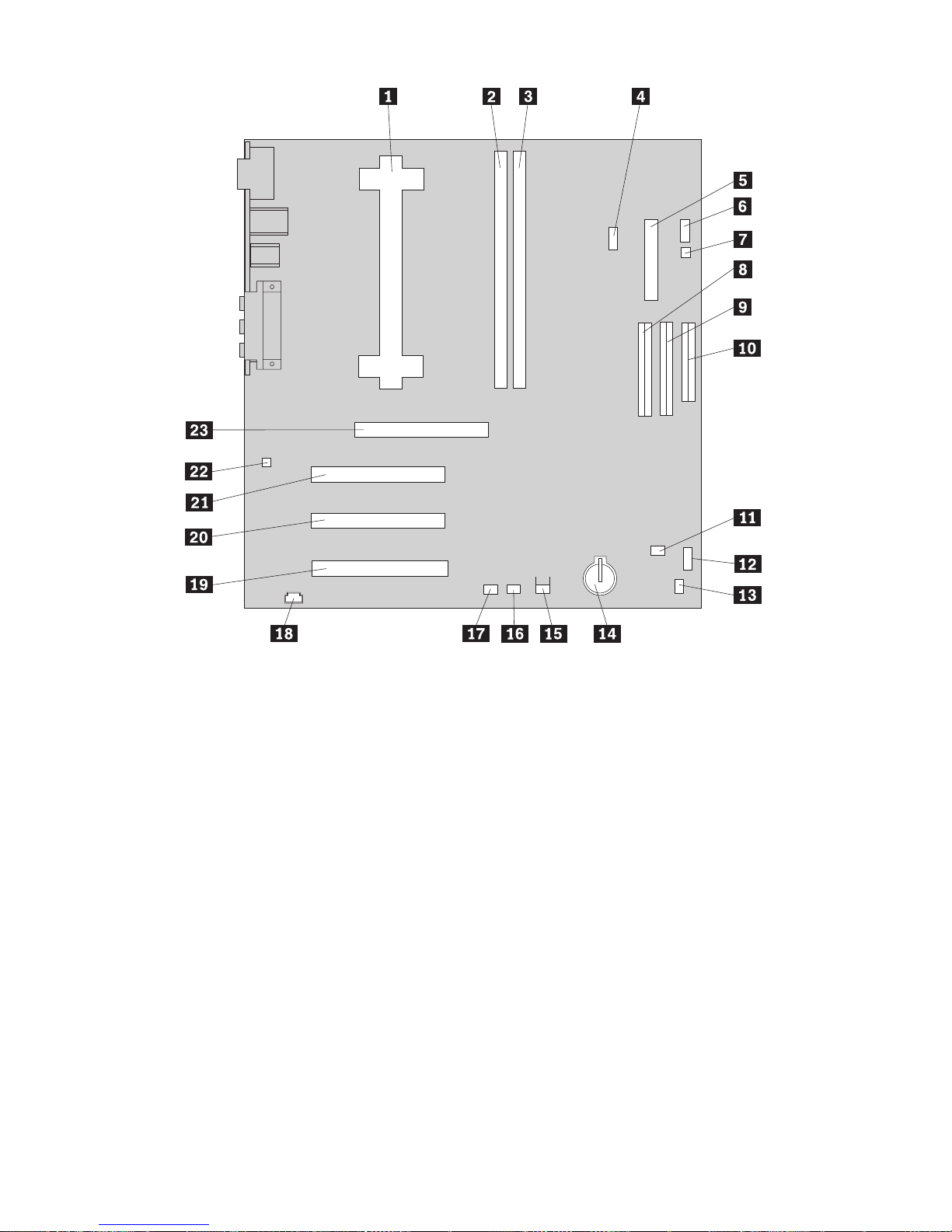
.1/ Microprocessor
.2/ DIMM 0
.3/ DIMM 1
.4/ Fan connector
.5/ Power connector
.6/ Switch/LED connector
.7/ RFID antenna connector
.8/ Primary EIDE connector
.9/ Secondary EIDE connector
.1ð/ Diskette drive connector
.11/ Fan connector
.12/ Large rocker switch (not on
all models)
.13/ Small rocker switch
.14/ Battery
.15/ Chassis intrusion detection
connector
.16/ Wake on LAN connector
.17/ Alert on LAN connector
.18/ CD-ROM connector
.19/ PCI adapter slot 1
.2ð/ PCI adapter slot 2
.21/ PCI adapter slot 3 (use this
slot for an Alert on LAN
adapter)
.22/ Chassis speaker connector
.23/ AGP adapter slot
Note: Your system board might not have all connectors that are shown.
Chapter 5. Installing options 75
Page 94

Working with memory
You can add memory to your computer to increase system performance.
Your computer has two connectors for installing memory modules that
provide up to a maximum of 1 GB of system SDRAM.
Your computer uses dual inline memory modules (DIMMs). The
IBM-installed DIMMs that come with your computer are unbuffered,
synchronous dynamic random access memory (SDRAM).
When installing or replacing DIMMs, the following rules apply:
Fill each system memory connector sequentially, starting at DIMM 0.
Use only 3.3 V, 133 MHz, unbuffered, SDRAM DIMMs.
Use only 64, 128, 256, or 512 MB DIMMs in any combination of
supported SDRAM DIMMs.
Note: To locate the memory connectors on the system board, see the
system board label inside your computer.
Before you begin:
Read “Safety information” on page ix and “Handling
static-sensitive devices” on page 61.
Read the instructions that come with the new system memory.
Turn off the computer and all other connected devices.
Disconnect all cables attached to the computer and remove the
computer cover (see “Removing the cover — tower model” on
page 68 or “Removing the cover — desktop model” on page 64).
Read “Accessing the system board” on page 74 to learn the
location of the parts on the system board.
Notes:
1. You might need to remove the power supply to gain access to the
DIMM sockets. See “Moving the power supply — desktop model” on
page 66 or “Moving the power supply — tower model” on page 71.
2. You might have to remove an adapter to access the DIMM sockets.
76 PC 300PL and PC 300GL User Guide
Page 95

To install a DIMM:
1. Remove the retaining screw from the adapter slot cover.
2. Open the module retaining clips on the DIMM socket.
3. Make sure that the notches in the DIMM are properly aligned with the
connector. Push the DIMM straight down into the connector until the
retaining clips close.
Notches
4. Reinstall any adapters that you removed. See “Installing adapters —
desktop model” on page 79 or “Installing adapters — tower model” on
page 80 for instructions to reinstall the adapter.
5. Reinstall the power supply if you removed it.
Chapter 5. Installing options 77
Page 96

What to do next:
To work with another option, go to the appropriate section.
To complete the installation, go to “Completing the installation” on
page 95.
Setting the diskette write-protect switch
The diskette write-protect switch controls whether you can write
information to a diskette using a diskette drive. The ability to prevent
writing to a diskette is particularly useful if you are concerned about the
security of information that can be obtained through a network.
Note:
This switch does not affect the ability to read information from a diskette.
Before you begin:
Read “Safety information” on page ix and “Handling
static-sensitive devices” on page 61.
Turn off the computer and all other connected devices.
Disconnect all cables attached to the computer and remove the
computer cover (see “Removing the cover — tower model” on
page 68 or “Removing the cover — desktop model” on page 64).
1. Locate the small rocker switch on the system board. See the label
inside the computer or “Identifying parts on the system board” on
page 74. It might be helpful to use a small screwdriver to set the
switch.
2. Set the switch as follows:
For read-only diskette operation, set switch 1 to the ON position.
Write-protect is now enabled.
For normal diskette operation, set switch 1 to the OFF position.
Write-protect is now disabled.
78 PC 300PL and PC 300GL User Guide
Page 97

Working with adapters
This section provides information and instructions for installing and
removing adapters.
PCI adapters
All adapters supported by your computer use Plug and Play technology that
enables the computer to automatically configure the adapter. For more
information, see “Updating the computer configuration” on page 97.
Adapter slots
Your computer system board has three peripheral component interconnect
(PCI) expansion slots used to connect adapters to the bus. There is also one
AGP adapter slot. You can install an adapter up to 330 mm (13 inches)
long in the desktop model and 228 mm (9 inches) long in the tower model.
Installing adapters — desktop model
Before you begin:
Read “Safety information” on page ix and “Handling
static-sensitive devices” on page 61.
Read the instructions that come with the new adapter.
Turn off the computer and all other connected devices.
Disconnect all cables attached to the computer and remove the
computer cover (see “Removing the cover — desktop model” on
page 64).
To install an adapter:
1. Remove the screw and slot cover for the appropriate expansion slot.
2. Remove the adapter from its static-protective package.
3. Install the adapter into the appropriate slot on the system board.
Chapter 5. Installing options 79
Page 98
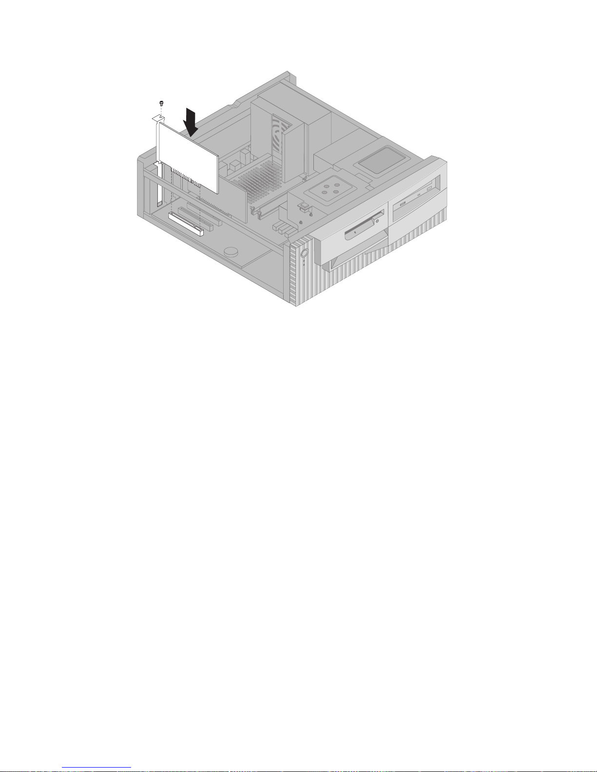
4. Install the screw that secures the adapter.
Note: If you are installing a Wake on LAN-supported network
adapter, attach the Wake on LAN cable that comes with the
adapter to the Wake on LAN connector on the system board.
(This might not be necessary with all computers.) If you also
want to take advantage of the Alert on LAN feature of your
computer, you must install your network adapter in PCI slot 3.
For the location of PCI slot 3 and the Wake on LAN connector,
see the diagram of the system board on the inside of your
computer.
5. Replace the cover.
What to do next:
To work with another option, go to the appropriate section.
To complete the installation, go to “Completing the installation” on
page 95.
Installing adapters — tower model
80 PC 300PL and PC 300GL User Guide
Page 99

Before you begin:
Read “Safety information” on page ix and “Handling
static-sensitive devices” on page 61.
Read the instructions that come with the new adapter.
Turn off the computer and all other connected devices.
Disconnect all cables attached to the computer and remove the
computer cover (see “Removing the cover — tower model” on
page 68).
Chapter 5. Installing options 81
Page 100

To install an adapter:
1. Move the power supply aside if necessary. See “Moving the power
supply — tower model” on page 71.
2. Remove the screw and slot cover for the appropriate expansion slot.
3. Remove the adapter from its static-protective package.
4. Install the adapter into the appropriate slot on the system board.
5. Install the screw that secures the adapter.
Note: If you are installing a Wake on LAN supported network
adapter, attach the Wake on LAN cable that comes with the
adapter to the Wake on LAN connector on the system board.
(This might not be necessary with all computers.) If you also
want to take advantage of the Alert on LAN feature of your
computer, you must install your network adapter in PCI slot 3.
For the location of PCI slot 3 and the Wake on LAN connector,
see the diagram of the system board on the inside of your
computer.
6. If you moved the power supply aside, replace it. See “Moving the
power supply — tower model” on page 71.
7. Replace the cover.
82 PC 300PL and PC 300GL User Guide
 Loading...