

Page 1
International Technical Support Organization
P/390 and R/390 with OS/390: An Introduction
August 1996
SG24-4847-00
Page 2

Page 3

IBML
International Technical Support Organization
P/390 and R/390 with OS/390: An Introduction
August 1996
SG24-4847-00
Page 4

Take Note!
Before using this information and the products it supports, be sure to read the general information under
Appendix B, “Special Notices” on page 169.
First Edition (August 1996)
Comments may be addressed to:
IBM Corporation, International Technical Support Organization
Dept 541 Mail Station P099
522 South Road
Poughkeepsie, New York 12601-5400
When you send information to IBM, you grant IBM a non-exclusive right to use or distribute the information in any
way it believes appropriate without incurring any obligation to you.
Copyright International Business Machines Corporation 1996. All rights reserved.
Note to U.S. Government Users — Documentation related to restricted rights — Use, duplication or disclosure is
subject to restrictions set forth in GSA ADP Schedule Contract with IBM Corp.
Page 5

Contents
Preface . . . . . . . . . . . . . . . . . . . . . . . . . . . . . . . . . . . . . . . . . . vii
How This Redbook Is Organized
The Team That Wrote This Redbook
Comments Welcome
. . . . . . . . . . . . . . . . . . . . . . . . . . . . . . . . . viii
........................... vii
........................ viii
Chapter 1. Product Descriptions
1.1 Functional Flow
. . . . . . . . . . . . . . . . . . . . . . . . . . . . . . . . . . . 3
1.2 P/390 Microprocessor Complex
1.2.1 Channel Emulator and Device Managers
1.2.2 Starting the P/390 Subsystem - Overview
1.3 PC Server System/390 System
1.4 RISC/6000 S/390 Systems
1.4.1 RISC/6000 S/390 (Model 7012-390)
1.4.2 RISC/6000 S/390 (Model 7013-591)
1.5 Support Programs
. . . . . . . . . . . . . . . . . . . . . . . . . . . . . . . . . 14
1.6 Adapters and Connections
1.7 OS/390 on CD-ROM
................................ 19
1.8 Positioning and Usage
1.8.1 Selecting a System
. . . . . . . . . . . . . . . . . . . . . . . . . . . 1
......................... 4
................. 7
................. 9
.......................... 10
............................. 12
..................... 13
..................... 14
............................ 18
............................... 20
.............................. 22
Chapter 2. Configurations and the P/390 Configurator
2.1 Server Workload Considerations (P/390)
2.2 PC Server System/390 Configurations
2.3 RISC/6000-591 S/390 Configurations
2.4 3270 Connection Configurations - Overview
2.5 Tape Configurations
2.6 The P/390 Configurator
Chapter 3. Installation
. . . . . . . . . . . . . . . . . . . . . . . . . . . . . . . . 34
.............................. 36
. . . . . . . . . . . . . . . . . . . . . . . . . . . . . . . . . 43
3.1 PC Server System/390 OS/390 Installation
3.1.1 Hardware Installation
3.1.2 OS/2 Installation
3.1.3 CM/2 Installation
3.1.4 P/390 Support Programs
3.1.5 OS/390 CD-ROM Installation
3.2 IPL and Use MVS
.................................. 49
. . . . . . . . . . . . . . . . . . . . . . . . . . . . . 43
. . . . . . . . . . . . . . . . . . . . . . . . . . . . . . . . 46
. . . . . . . . . . . . . . . . . . . . . . . . . . . . . . . 46
........................... 47
......................... 48
3.3 RISC/6000 S/390 OS/390 Installation
3.3.1 Hardware Installation
3.3.2 AIX Installation
3.3.3 P/390 Support Programs
3.3.4 OS/390 CD-ROM Installation
3.3.5 IPLing OS/390
. . . . . . . . . . . . . . . . . . . . . . . . . . . . . 50
. . . . . . . . . . . . . . . . . . . . . . . . . . . . . . . . . 50
........................... 53
......................... 54
. . . . . . . . . . . . . . . . . . . . . . . . . . . . . . . . . 57
3.4 Expanding the CD-ROM Systems
3.5 Working With the P/390 Configurator
3.6 Non-RAID Installation (PC Server)
3.7 Installing Other MVS or OS/390 Systems
3.7.1 Creating and Initializing Disk Volumes
.................... 23
..................... 24
....................... 29
.................. 30
................... 43
...................... 50
........................ 58
...................... 59
........................ 63
.................... 64
.................. 65
.............. 23
Chapter 4. Device Managers and Commands
4.1 Starting Device Managers
4.2 Device Managers for DASD
Copyright IBM Corp. 1996 iii
............................ 69
............................ 70
................... 69
Page 6

4.2.1 AWSCKD . . . . . . . . . . . . . . . . . . . . . . . . . . . . . . . . . . . . 70
4.2.2 AWSFBA
4.3 Device Managers for Simple Terminals
4.3.1 AWS3274 (P/390)
4.3.2 AWS3274 (R/390)
4.3.3 LAN3274 (P/390 only)
4.4 Device Managers for Tape Drives
4.4.1 AWSTAPE Device Manager
4.4.2 SCSI34x0 and AWS34x0
4.4.3 ISITAPE Device Manager (P/390 Only)
4.5 Device Managers for Unit Record
4.5.1 AWS2540
4.5.2 AWS2821 Device Manager
4.5.3 AWS3215 Device Manager
4.6 Device Managers for Communications
4.6.1 LAN3172 Device Manager (P/390)
4.6.2 LAN3172 Device Manager (R/390)
4.6.3 WAN3172 Device Manager (P/390)
4.6.4 WAN3172 Device Manager (R/390)
4.6.5 LCS3172 Device Manager (P/390)
4.6.6 LCS3172 (R/390)
4.6.7 MGR3172 (P/390 OS/390 Only)
4.6.8 AWSICA Device Manager (P/390 Only)
4.6.9 AWSPBS Device Manager (Normally VM and VSE)
4.7 Other Device Managers
4.7.1 AWSC370 Device Manager
4.7.2 LAN3088 Device Manager (P/390 only)
4.7.3 AWS2703 Device Manager (P/390 only)
4.7.4 AWSOMA Device Manager (P/390 only)
4.7.5 AWSPCSRV (VM Only)
4.7.6 AWSMOUNT Command (P/390 and R/390)
4.7.7 AWSSTAT (P/390 only)
4.7.8 AWSSTART
4.7.9 AWSPROF Command (P/390)
4.7.10 CLRIO Command (P/390)
4.7.11 AWSCFG Commands (P/390)
4.7.12 DEV2NAME
4.7.13 IPL Command (P/390)
4.7.14 ipl390 Command (R/390)
4.7.15 LTRENAME Command (P/390 Only)
4.7.16 RDEVMAP Command (P/390 Only)
4.7.17 BLDLIST Command (P/390)
4.7.18 C370MAP Command (P/390)
4.7.19 AWSCMLT Command (P/390)
4.7.20 TRCC370 Command (P/390)
4.8 Other Commands
. . . . . . . . . . . . . . . . . . . . . . . . . . . . . . . . . . . . 75
.................... 75
................................ 75
. . . . . . . . . . . . . . . . . . . . . . . . . . . . . . . 76
............................. 78
........................ 82
......................... 82
........................... 86
................... 89
........................ 90
. . . . . . . . . . . . . . . . . . . . . . . . . . . . . . . . . . . . 90
.......................... 92
.......................... 96
..................... 96
..................... 97
..................... 99
.................... 100
.................... 101
.................... 101
. . . . . . . . . . . . . . . . . . . . . . . . . . . . . . . 103
...................... 104
................. 105
.......... 106
............................. 106
........................ 106
................. 110
................. 110
................. 112
........................... 113
............... 113
........................... 115
. . . . . . . . . . . . . . . . . . . . . . . . . . . . . . . . . . 115
....................... 116
......................... 116
....................... 116
. . . . . . . . . . . . . . . . . . . . . . . . . . . . . . . . . 117
........................... 117
......................... 117
................... 118
................... 118
....................... 118
....................... 119
...................... 119
....................... 119
. . . . . . . . . . . . . . . . . . . . . . . . . . . . . . . . . 119
iv P/390 MVS
Chapter 5. Other Topics
. . . . . . . . . . . . . . . . . . . . . . . . . . . . . . . 121
5.1 S/390 Manual Operations
5.2 Diagnostic Facilities
5.3 Tape Drives
. . . . . . . . . . . . . . . . . . . . . . . . . . . . . . . . . . . . 127
. . . . . . . . . . . . . . . . . . . . . . . . . . . . . . . 123
5.4 XTAPE Product (P/390 Only)
5.5 OS/390 Device Planning
5.6 Security
. . . . . . . . . . . . . . . . . . . . . . . . . . . . . . . . . . . . . . 133
5.7 OS/2 and Hardware Tuning
............................ 121
.......................... 131
............................. 132
........................... 134
Page 7

5.8 System/390 Activity Window .......................... 136
5.9 Device Manager Letters and Names
5.10 3270 Emulator Keyboards
5.11 Writing a Device Manager
5.12 Send and Receive
................................ 138
5.13 Backing Up OS/390
........................... 137
........................... 138
............................... 139
5.14 OS/390 Performance and Capacity (P/390)
5.15 tn3270 Emulators
5.15.1 xant 3270 Emulator
5.15.2 hcon 3270 Emulator
5.16 AWSICA and BSC NJE
5.17 Internet Address
5.18 LAN Connection
. . . . . . . . . . . . . . . . . . . . . . . . . . . . . . . . 149
............................ 151
............................ 152
............................. 153
. . . . . . . . . . . . . . . . . . . . . . . . . . . . . . . . . 154
. . . . . . . . . . . . . . . . . . . . . . . . . . . . . . . . . 154
..................... 137
................. 140
Chapter 6. Frequent Questions
6.1 PC Server System/390 Systems
6.2 RISC/6000 S/390 Systems
6.3 Questions Common to Both Bases
. . . . . . . . . . . . . . . . . . . . . . . . . . . 155
........................ 155
............................ 157
...................... 158
Appendix A. AWS2821 Translation Table (P/390)
Appendix B. Special Notices
Appendix C. Related Publications
Appendix D. How To Get ITSO Redbooks
. . . . . . . . . . . . . . . . . . . . . . . . . . . . 169
. . . . . . . . . . . . . . . . . . . . . . . . . 171
..................... 173
D.1 How IBM Employees Can Get ITSO Redbooks
D.2 How Customers Can Get ITSO Redbooks
D.3 IBM Redbook Order Form
Index
. . . . . . . . . . . . . . . . . . . . . . . . . . . . . . . . . . . . . . . . . . . 177
........................... 175
.................. 174
................ 167
............... 173
Contents v
Page 8

vi P/390 MVS
Page 9

Preface
This document introduces the IBM PC Server System/390 (commonly known as
the P/390), with special emphasis on its use with OS/390. The discussion also
includes the IBM RISC/6000 with S/390 Server on Board (commonly known as the
R/390), but in less detail. The emphasis is on understanding the nature of these
products, with their advantages and limitations. The reader is assumed to be a
technical professional, with an MVS background. Typical configurations are
described. Installation is described, briefly, as it is covered in detail in other
documents. A small amount of observed performance data is included.
(181 pages)
This replaces an earlier redbook
GG24-2538. The general discussion context is for a system used for
programming development, and suitable configurations are described for this
purpose.
OS/390 or MVS.
introduction to OS/390 running on the PC Server System/390 or the RISC/6000
S/390.
The reader is assumed to have a system programmer′s knowledge of
This document is not an introduction to OS/390. It is an
How This Redbook Is Organized
The descriptions in this document correspond with Version 2.1 of the P/390
support programs, level 4.0.0.1 of the R/390 support programs, and the IBM
S/390 Developers′ Association version of OS/390 on a CD-ROM. Later updates
and releases may change some details, but the basic comments and
recommendations should remain valid.
You should have
′
s Guide for MVS/ESA
User
Messages and Codes
These documents contain detailed installation instructions. You should also
have the redbooks
Printing with MVS on the IBM PC Server System/390
SG24-4612, for more information in these areas.
PC Server 500 System/390: Installation, Configuration, and
MVS and the IBM PC Server 500 System/390
, SA22-7210-1, and
, SA22-7227, before installing your P/390 MVS system.
Connectivity on a PC Server System/390
PC Server 500 System/390:
, SG24-4624, and
,
,
The first chapter of this document describes the products concepts and
positioning, and describes the general operation of the products.
The second chapter describes the variety of configurations that can be used, and
how the P/390 configuration utility is used.
The third chapter describes, briefly, the steps required to install a system -- from
Server hardware to OS/390.
The fourth chapter provides detailed information about the various device
managers provided with the P/390 support programs.
The fifth chapter contains discussions of a number of areas related to OS/390
operation. A limited amount of performance information is provided.
The sixth chapter lists many frequently asked questions about these products,
with associated answers.
Copyright IBM Corp. 1996 vii
Page 10

The Team That Wrote This Redbook
This document is the result of work in the International Technical Support
Organization at the Poughkeepsie Center. The author was Bill Ogden.
We extend thanks to the following people for substantial assistance in producing
this document:
•
Chuck Berghorn - IBM P/390 Development (Poughkeepsie)
•
Bohdan Demczar - IBM Development (Poughkeepsie)
•
Marty Ziskind - IBM P/390 Development (Poughkeepsie)
•
Louis Voerman - IBM P/390 Development (Poughkeepsie)
•
Carmine Castaldo - IBM R/390 Development (Poughkeepsie)
•
Joel Naslow - IBM P/390 Development (Poughkeepsie)
•
Doris Conti - IBM Development (Poughkeepsie)
•
Gordon Chamberlain - Interprocess Systems, Inc. (Roswell, Georgia)
Comments Welcome
We want our redbooks to be as helpful as possible. Should you have any
comments about this or other redbooks, please send us a note at the following
address:
redbook@vnet.ibm.com
Your comments are important to us!
viii P/390 MVS
Page 11

Chapter 1. Product Descriptions
The products discussed in this document are built around a single adapter card,
the S/390 Microprocessor Complex. This adapter is often referred to as the
P/390 adapter
Complex” on page 4. The adapter is part of several products, one based on an
IBM PC Server and two based on RISC/6000 systems.
To avoid writing “PC Server or RISC/6000 system” hundreds of times throughout
this document, we will refer to a generic “Server” in any discussion that applies
to both PC Server and RISC/6000 based products. This usage ignores the
common distinction between
purpose of this document. We elected not to use the word “host” for the PC
Server or RISC/6000 base system. Although it is a more logical word, it is very
firmly associated with mainframes, and could be especially confusing in a
document dealing with OS/390 and MVS.
, and is explained in some detail in 1.2, “P/390 Microprocessor
workstations
and
servers
, and is solely for the
The proper names for the products are
with System/390 Server On Board
. They are often referred to as P/390 and R/390
IBM PC Server S/390
and
IBM RISC/6000
systems, respectively, although these names are not strictly proper, and may
1
confuse the adapter card with the total system.
The key portion of the names,
“S/390,” indicates the unique nature of the products. With proper setup of the
underlying Server systems, they provide System/390 environments. OS/390
(MVS), VM, and VSE, with all their subsystems and applications, will run on
these systems -- with very few limitations.
We will use the term “OS/390” to mean both OS/390 and any reasonably current
release of MVS. For the purposes of this document, there is no distinction
between OS/390 and MVS. This document is about P/390 OS/390; much of what
is discussed also applies to VM and VSE systems, but they are not the subject
here and are seldom mentioned. Also, as a final note on terminology, we will
use “storage” rather than “memory” for P/390 storage.
We will reference the document
P/390 & R/390: OS/390 New Owner′s Cookbook
SG24-4757, a number of times and simply refer to it as the
2
Cookbook
,
. It contains
brief, specific instructions for some of the basic administrative tasks needed with
OS/390. The descriptions are based on the S/390 Developers′ Association
OS/390 CD-ROM system, which is described later in this document. (The
Cookbook
is scheduled to be available in late 1996.)
The P/390 adapter contains a S/390 processor. It does not emulate or simulate a
is
S/390 processor, it
S/390 I/O subsystem. The underlying Servers are used to emulate
a S/390 processor. While it is a S/390 processor, it is not a
3
the I/O
subsystem and a selected set of S/390 I/O devices. Most of this document, as
1
Thus a “P/390 system” could be either a PC Server or a RISC/6000 system, with the “P/390” referring to the S/390 adapter.
In another context, “P/390” may refer to the PC Server S/390 system, in contrast to an R/390 system. The context of a
discussion usually indicates which meaning is implied.
2
Memory and storage are the same thing, but mainframe terminology is usually “storage” and PC/RISC terminology is usually
“memory”
3
Some documents imply subtly different meanings for the words “simulate” and “emulate.” This document is not so
sophisticated, and arbitrarily uses the word “emulate” when describing the functions of the P/390 support programs.
Copyright IBM Corp. 1996 1
Page 12

well as other redbooks dealing with these products, is concerned with this
emulation of S/390 I/O functions.
There are differences between these systems and a S/390 mainframe, but these
differences are generally outside the normal operating system and application
program interfaces. The differences include:
•
System partitioning into multiple system images (“LPARs”) is not available.
•
Multiprocessor functions are not available.
•
Shared DASD, with a mainframe or another P/390 OS/390 system, is not
available (at the time this was written).
•
IOCDS configuration functions are not used. These are replaced by (simpler)
I/O configuration controls through an OS/2 or AIX program, and a file known
as DEVMAP.
•
Integrated communications I/O, as found on IBM 9370 and 9221 systems, is
emulated through various Server drivers. Not all integrated communications
functions are emulated. (OS/390 does not support these integration
communication adapters for VTAM use. OS/390 can use them as basic
bisync devices, such as JES2 might use, but this is no longer common and is
not formally supported.)
•
Sysplex connections are not supported.
•
Parallel bus and tag channel connections are available, using a S/370
channel adapter card and a driver program on Servers. Only certain devices
are supported through this path. In particular, DASD connections are not
supported at this time.
•
ESCON channel connections are not available at this time.
•
Integrated console attachments (such as used on IBM 4381, 9370, and 9221
systems) are not supported. The Server provides a 3270 emulator which
operates as though an IBM 3174 control unit were attached. The emulator
provides multiple 3270 sessions, and can be used for both console and user
sessions.
•
Expanded storage functions are supported. You can partition the S/390
storage into standard and expanded storage. However, there is a one-to-one
tradeoff between standard and expanded storage, and most users elect to
use full standard storage and no expanded storage.
2 P/390 MVS
In addition to emulating a S/390 I/O subsystem, the Server uses P/390 adapter
interfaces to initiate IPLs, perform various S/390 resets, and provide most S/390
operator functions -- such as register and storage displays.
A package of P/390 support programs must be installed in the Server to provide
the I/O emulation and console functions for programs executing in the P/390
adapter. These
P/390 support programs
are a key part of the complete products.
(In keeping with the slightly confusing terminology that exists for these products,
P/390 support programs are used to support the P/390 adapter, which is used in
both P/390 and R/390 systems. There are two packages of P/390 support
programs: one for P/390 systems and one for R/390 systems.)
Page 13

1.1 Functional Flow
The functional flow shown in Figure 1 is very important in understanding these
systems, and we suggest you take time to understand the concepts involved.
While the figure is a high-level abstraction, it represents a Server with a P/390
adapter, running an OS/390 application. Two processors are indicated: the left
side (in the figure) is the S/390 processor, and the right side is the Server
processor (a Pentium or RISC processor). Each “side” has its own storage.
processors do not share storage
have 128 MB storage; the size of Server memory will vary, but it will have at
least 32 MB.
In the figure, an OS/390 application is executing -- this means it is executing
S/390 instructions, just as though it were running on a mainframe. At the same
time, the Server can be executing its own workload
go like this:
•
•
•
•
The
. For OS/390, the P/390 adapter will normally
4
. The flow of control might
The OS/390 application encounters an I/O function, such as a GET macro.
This passes control to an access method. The access method may construct
a channel program and issue an EXCP request (or something similar) to
OS/390. For example, this might be a read operation for a 3380 disk at S/390
address 120. As far as OS/390 is concerned, it thinks it has a “real” 3380 at
this address.
OS/390 gets control, schedules the channel program, and eventually issues
5
an SSCH
instruction. Up to this point, operation has been exactly the same
as mainframe operation.
The SSCH instruction works differently than on a mainframe. It constructs
several control blocks, in control storage not visible to OS/390, and causes
an interrupt in the Server system.
Figure 1. Conceptual Flow of Control
4
We will discuss the practicalities of additional Server workloads later.
5
Start Subchannel. This is the modern equivalent of the original SIO (Start I/O) instruction in the S/360.
Chapter 1. Product Descriptions 3
Page 14

•
A P/390 support program (running under OS/2 or AIX) gets control (based on
the interrupt from the P/390 adapter).
•
It gives control to the P/390 channel emulator program. As its name implies,
this program emulates many of the functions of a S/390 channel. It sustains
a number of parallel operations in the “channel,” permitting OS/390 to have
multiple outstanding I/O operations. It interprets portions of CCWs, and
provides initial condition codes for SSCH instructions.
•
The channel emulator determines which device type and address are
involved (a 3380 disk at address 120, in this example, based on the
definitions in a DEVMAP that is not shown), and gives control to a device
manager program. At the same time, it usually returns initial status to the
P/390, completing the SSCH instruction. The P/390 continues executing
S/390 instructions, running in parallel with the emulation programs on the
Server. In the Server, a DEVMAP (device map) is used to relate S/390
addresses (such as 120) to particular device managers (such as the one
used to emulate a 3380 disk). The DEVMAP is maintained by the P/390
configurator program (operating on the Server), and is remotely similar to
the IOCDS of a mainframe. The DEVMAP is described in considerable detail
later.
•
The P/390 support programs include many device managers, for different
types of devices. In general, a device manager emulates a particular type of
6
“real” mainframe device.
. In this example, the particular device manager
(which would be the AWSCKD.EXE program for a P/390 system) emulates a
3380 disk drive.
•
The device manager uses a real Server I/O device, and issues normal
READ/WRITE instructions through OS/2 or AIX to access the device. The
device manager calls the channel emulator, as needed, to transfer data
to/from P/390 storage. The channel emulator does not need to interrupt the
P/390 to do this; it can access P/390 storage by using a movable
window
is accessed from the Server side.
•
When the device manager completes the requested function, it notifies the
channel emulator. The channel emulator then causes an I/O interruption in
the P/390, and creates a CSW (channel status word) with appropriate
indicators, such as channel end and device end.
that
While the analogy is not exact, the P/390 channel emulator functions much as a
mainframe channel does, and P/390 device managers tend to perform the
functions of mainframe control units.
1.2 P/390 Microprocessor Complex
This section provides slightly more detail about the system. None of this
material is necessary for system use, but it may help you become more
comfortable with general concepts. The S/390 processor card used is shown in
Figure 2 on page 5. It is a Micro Channel adapter card. The S/390 processor is
a single chip on the card. The processor has approximately 220K gates and
uses 420 signal pins of the 647-pin mount. (The other pins are used for power
and grounds.) It has 32KB of control storage and uses horizontal microcode with
136 bits per word. Internal data flow is 64 bits wide.
6
This is not exactly the case when a S/370 Channel Emulator/A adapter is used, but this is described later.
4 P/390 MVS
Page 15
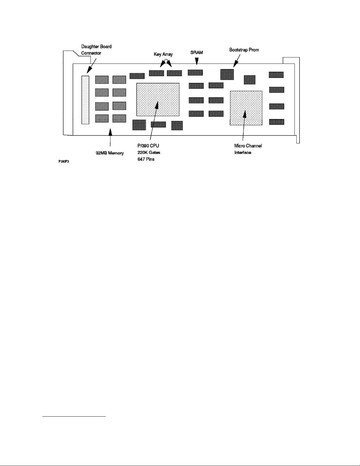
Figure 2. P/390 Processor Complex Adapter
The basic P/390 adapter has 32 MB storage. When a daughter card is used (to
7
add 96 MB additional S/390 storage), the storage is interleaved.
The 32MB
storage on the S/390 processor card is not the “first 32MB.” We assume the
additional 96 MB is always used when OS/390 is used. The daughter card
requires a Micro Channel slot; it uses the slot for power and ground connections,
but does not transfer data through the Micro Channel.
The P/390 adaptor contains its own timing circuits, and its clocking is
independent of the Server. The current P/390 contains a 71 MHz clock that is
divided into a four-phase clock of approximately 17.7 MHz. Different S/390
instructions require different numbers of clock cycles to complete, but the
average performance is approximately 4.5 S/390 processor MIPS.
An important design goal was to avoid any modifications to OS/390 (or any other
S/390 operating system used with the system). The key to doing this was to
move all I/O operations to the OS/2 side of the system. No modifications are
required for OS/390 to run on this system, although some reconfiguration may be
appropriate.
The S/390 microprocessor is a single chip. It is controlled by microcode that is
8
loaded when the P/390 subsystem is started.
The S/390 processor (through
hardware and microcode) implements the full S/390 subchannel architected
interfaces; that is, a S/390 program can issue all the defined I/O instructions and
work with the control blocks associated with these instructions. The subchannel
control blocks (as used in all System/390 platforms) are the link between the
S/390 processor and the OS/2 support programs.
When the S/390 program (usually OS/390′s IOS code) issues an SSCH instruction
(Start SubChannel), an interrupt is generated for the OS/2 side of the processor.
The OS/2 code (part of the I/O subsystem provided on the P/390 diskettes) can
7
Two different daughter cards were originally available, one with 32 MB and one with 96 MB. The 32 MB card (which brought
the total P/390 adapter to 64 MB) is no longer available.
8
The microcode is included on the P/390 support diskettes.
Chapter 1. Product Descriptions 5
Page 16

access S/390 memory and can “see” the ORB, CCWs, I/O areas, and so forth,
that are associated with the I/O operation. A combination of OS/2 code and
P/390 microcode maintains SCHIBs that correspond to emulated subchannels.
An IOCDS is not used. A n equivalent mapping operation (and an IOCDS is
essentially a map) is built from the DEVMAP file you build with the P/390
10
subsystem configurator function.
There is a single path to each emulated
device.
The S/390 processor is a full System/390 ESA processor. It executes S/390
instructions as its native instruction set. In addition:
•
All of the “ESA” and “XA” instructions (such as Branch and Save) are
present.
•
Extended instructions are available, including string instructions, square root,
cancel I/O, compression, expanded sorting, move inverse, move page(2),
PER-2 and extensions, private space, data spaces, ACL protection, address
limit checking, broadcast purging, subspace group, compare until substring
equal, incorrect length indication suppression, set address space control
fast, storage protection override, suppression on protection, and so forth.
•
Some “assist microcode” is present, including Interpretive Execution
(Interception format 2, PER extensions, VM data space, Storage-Key
functions), add FRR, SVC assist, Obtain/Release Local Lock, Obtain/Release
CMS lock).
•
Low address protection, fetch protection override, and public storage key
control are supported.
9
A few other considerations are:
•
Emulated disks (3380s, for example) do not have a “CE” track. They need to
be initialized as though they were minidisks. (Both the stand-alone ICKDSF
program and the OS/390 version do this.)
•
In general, diagnostic CCWs are not fully processed. The intention is that all
“real” device recovery is done by the OS/2 programs, and OS/390 will see
only successful I/O operations or simple failures (“device not ready,” for
example). OS/390 will not be called upon to issue complex I/O diagnostic
operations. IBM S/390 I/O maintenance tools may not work correctly (and
should not be used).
•
Obscure sense bits are not emulated.
•
Older devices, potentially attached through a S/370 Channel Emulator/A
11
adapter, have not been tested.
•
The S/370 Channel Emulator/A adapter does not support “Read Backward”
commands. (These commands were used by the SORT program, in
conjunction with 3420 tape drives, many years ago. The only current usage
of read backwards that we have encountered is with OS/390 standard label
processing; special-case code is included to handle this usage.)
9
See the S/390 Principles of Operation manual for definitions of these terms.
10
Suitable DEVMAPs are included with the various operating system releases on CD-ROM that are intended for use with these
systems.
11
For example, a real 3420 tape drive has a sense bit that indicates that the “left reel is turning.”
6 P/390 MVS
Page 17

•
There is no hardware support for 2K storage keys; only 4K keys are
supported. (VS1 used 2K keys.)
The P/390 subsystem provides several trace functions. By using the Trace icon,
trace data can be displayed or sent to a file. There are two trace types:
1. Kernel trace, that records all S/390-Server interactions
2. Device trace, that records only interactions associated with a specific
emulated device
The normal trace table (this is the P/390 subsystem trace table, which has no
relation to the OS/390 trace table) has 2000 entries. It is most useful for
debugging emulated I/O problems.
1.2.1 Channel Emulator and Device Managers
To a certain extent, the P/390 support programs are structured like mainframe
hardware. The CPU and central storage communicate with channels, the
channels communicate with control units, and the control units work with
devices. In our case, the AWSCHAN.EXE (using the P/390 module names for
these examples) progr am is the channel. On one side, it works with CPU
interrupts, I/O requests, and storage, and on the other side it works with control
units, emulated or real.
The AWSCKD.EXE device manager program is an example of an emulated
control unit. Real control units can be attached through the S/370 Channel
Emulator/A adaptor, although the AWSC370.EXE module is needed to interface
the channel (AWSCHAN) to the adapter. The Server system and devices, to
some extent, correspond to the end devices that are managed by control units.
The analogy with mainframe hardware is not exact, but it is close enough to help
understand the general design of the P/390 support programs.
Like a mainframe channel, AWSCHAN supports multiple concurrent activities
between the CPU and various control units. A mainframe channel is often
limited to eight control units, while AWSCHAN has no fixed limit to the number of
device managers (emulated control units) it can manage. It is limited to 255 total
devices, as seen by the P/390 configurator (which is described later).
AWSCHAN provides handling of all S/390 I/O instructions, initial handling of all
CCWs, manages all accesses between device managers and the S/390 main
12
storage
, and manages all I/O interrupts sent to the S/390. It general, it handles
many parallel functions. Internally, it uses a fixed number of buffers to pass data
to/from device managers and S/390 storage. AWSCHAN is both a very complex
module, and a key module for P/390 support, and its developers have continually
refined and improved it. Some of these improvements account for the dramatic
performance improvements included in Version 2.1 of the P/390 support
programs.
13
The key improvements were in handling (emulated) PCI
functions. OS/390
program fetch, which involves reading program text and relocation information
from disk, and relocating programs as they are placed into main storage, is
12
There are a few exceptions to this, in which other programs or adapters directly access S/390 storage, but these exceptions
do not negate the general design.
13
Program Controlled Interruption. This is a flag in a CCW that causes the channel to interrupt the CPU when operation for that
CCW is started. The channel continues to process the CCW and the rest of the channel program. After receiving the interrupt,
Chapter 1. Product Descriptions
7
Page 18

much faster if PCI is fully used. The same changes in AWSCHAN also improved
the processing of partitioned data set directories. These two areas, PCI fetch
and PDS directory processing, are two of the most important underlying
functions for OS/390 performance.
The device managers are the key to emulating S/390 devices. A device manager
has these characteristics:
•
It emulates a device and its control unit.
•
It interprets CCWs and performs whatever OS/2 I/O is required to emulate
the requested I/O.
•
It generates sense data as required.
•
It may emulate multiple devices (such as multiple 3380 drives) and multiple
device types (such as 3380 and 3390).
•
It may (or may not) be multithreaded. A few major device drivers (such as
AWSCKD for the P/390) are multithread, with one thread for each emulated
device.
•
Some serialization may be enforced to allow orderly operation by the device
manager code.
•
Each device manager decides how it wants to handle overlap of multiple
devices. Complex drivers (such as AWSCKD) provide as much overlap as
possible (and are usually limited by the underlying Server I/O design and
devices).
There is no requirement for a device manager to use multiple threads; the
managers for the R/390 generally do not use threads while many P/390
managers do use threads. Figure 3 shows the basic threads of a simple device
manager for a P/390 base. The main line code receives an initial I/O request
and provides initial status (so the SSCH instruction can complete). Final status
(when the emulated I/O operation is complete) is provided by the back-end code
(and thread). Asynchronous functions (such as an attention interrupt) are
handled by the async code and thread.
The support programs have several interfaces to the S/390 processor card:
1. Interrupts (both ways).
2. Shared Memory. The Server can read S/390 storage through a movable
window. Either real or virtual addresses can be used.
3. A communications buffer (on the adapter card). This buffer contains ICBs
(interrupt control blocks) and SCHIBs (subchannel information blocks).
4. Manual operations functions such as alter/display, IPL, stop, start, and so
forth.
The SSCH operation is the primary link between S/390 code and the supporting
P/390 subsystem. The complete process, using the channel emulator and device
manager, goes like this:
1. OS/390 issues an SSCH instruction to start an I/O operation.
the CPU can dispatch a program that processes data received from the channel thus far. The CPU could also chain additional
CCWs, depending on the data obtained earlier, to the channel program.
8 P/390 MVS
Page 19

Figure 3. General Thread Structure for Device Manager
2. P/390 microcode moves data to the SCHIB, completes a ICB, and interrupts
the Server.
3. The P/390 router gets control and passes control to the P/390 channel
support program.
4. The channel module:
a. Checks if the correct device manager is available
b. Checks the emulated device state
c. Releases the S/390 with CC=0 (if the device state warrants it)
d. Routes the SSCH request to the device manager
5. The device manager:
a. Validates the CCW
b. Passes initial status to the channel
c. Interprets the CCWs, performs Server I/O, emulates CCW chaining,
provides PCI interrupts, and so forth
d. Returns final status to the channel
The timing characteristics of this process do not exactly match the
characteristics of a mainframe. If programs follow correct coding practices (and
all the major MVS products do, as far as we know) there are no problems. If a
program modifies CCWs too soon, there could be incompatibilities. Good
program design calls for using PCIs before modifying active CCW chains, and
this works properly.
1.2.2 Starting the P/390 Subsystem - Overview
When the Server system is booted, the P/390 adapter is idle. The Server must
load P/390 microcode and then use control instructions to start P/390 processing.
There is no requirement to use the P/390 adapter, of course. A user can boot
OS/2 or AIX and use it normally. The P/390 adapter becomes active only when
the appropriate commands are issued to start it. The P/390 functions are useful
only when a S/390 program is available (on disk or tape) to execute. The S/390
program to be executed is normally the operating system (OS/390), but it could
be a standalone program such as ICKDSF or a tape-to-disk restore program.
Chapter 1. Product Descriptions 9
Page 20

The P/390 functions are normally started with the IPL.CMD REXX command
procedure. (The “IPL P/390” icon issues this command internally.) The startup
operation goes like this:
1. Issue the IPL.CMD command (usually by clicking on an icon).
2. IPL.CMD starts AWSMAIN (one of the P/390 support programs).
3. AWSMAIN, among other things:
a. Loads the S/390 processor microcode (if it is not already loaded)
b. Loads the current DEVMAP.
c. Starts AWSCHAN (to begin emulated channel operations)
d. Builds SCHIBs to correspond to devices defined in the DEVMAP.
4. Start all the device managers. Each manager will decide (by inspecting the
DEVMAP details) whether it is needed.
5. Wait for the device managers to initialize.
6. Issue an IPL function to the S/390 processor.
7. The S/390 processor executes an SSCH instruction to the I/O address
specified in the IPL function.
8. The I/O operation is emulated by the appropriate device manager.
9. Control is given to the program instructions read by the initial I/O operation.
10. Operation continues, and OS/390 (or whatever was selected) loads itself.
1.3 PC Server System/390 System
The original P/390 (announced mid-1995) used a PC Server 500 as the base. T he
current P/390 (announced mid-1996) uses a PC Server 520 as the base.
Characteristics include:
•
CPU - a 133MHz Pentium (The PC Server/500 had a 90Mhz Pentium.)
•
Memory - 32MB (default) to 256MB 70 ns, 2-way interleaved on a 64-bit
interface. ECC error detection and correction is standard.
•
Six Micro Channel and two PCI slots are included. (The Server 500 had eight
Micro Channel slots.)
•
Two serial ports and two parallel ports
•
A SCSI adapter is standard, on the mother board. (The Server 500 did not
have this.)
•
An SVGA adapter is standard, on the mother board. (The Server 500 did not
have this.)
•
Enclosure - 18 disk bays (!), up to 38GB internal disk storage (with
combinations of 1 inch, HH, and FH drives), 434 watt power supply, variable
speed fans, lockable media door, tamper-evident covers, LogicLock (C2
functionality), message LED, and other features.
•
Systems intended for P/390 use include:
10 P/390 MVS
− A fast/wide SCSI RAID adapter with two or three channels. (The Server
500 RAID adapter had two channels.)
− A 4mm tape drive and a CD-ROM drive.
− Five 2.25 GB fast/wide disk drives
Early experience with the PC Server 520 indicates that the faster Pentium
processor leaves more capacity available for OS/2 work (while OS/390 is also
running). It does not cause OS/390 to run significantly faster, although we expect
it will allow more effective parallel usage of disk drives.
Page 21

Figure 4. Basic PC Server System/390 for OS/390. This is the base configuration of a system intended for use
with OS/390. Use with OS/390 implies that the additional P/390 memory “daughter card” is installed, and five 2.25
GB disk drives are installed. Later versions of the P/390 may use the planar SCSI adapter for the 4mm tape and
the CD-ROM drive.
This basic system, as shown in Figure 4, leaves four Micro Channel slot and one
PCI slot available for additional adapters. One potential disk bay slot may be
lost in providing a SCSI connection for the 4mm tape drive, depending on the
internal connections selected. The two lower disk bays can each be used for six
thin (one inch high) disk drives, or three half-high disk drives. All disks must be
mounted in
hot swap trays
. (Note that the integrated SCSI adapter, on the planar
board, could also be used to drive the CD-ROM and 4mm tape drive since both
this adapter and these devices use 8-bit SCSI interfaces. Production systems,
built after this was written, may use this method.)
The RAID adapter controls the first bay of disk drives (five or six drives) and
possibly the CD-ROM and 4mm tape drive. It has one or two more channels.
The second channel is used for another bank of internal disk drives. The third
channel can be used for yet another bank of internal disk drives, or for external
SCSI devices. In general, the planar SCSI adapter would be the first choice for
external SCSI connections.
Using the two lower disk bays requires two
trays connect) and one additional
power supply
backplanes
. You can order these when your
(into which the hot swap
initial system is built, or you can order them later.
A large number of configurations are possible, based on this initial configuration.
Several of these are described in Chapter 2, “Configurations and the P/390
Configurator” on page 23. The base configuration, as shown in the figure, is
completely sufficient for OS/2 and has sufficient disk space to emulate 3380
drives to load and run OS/390, with space for DLIBs, CICS, DB2, work volumes,
Chapter 1. Product Descriptions 11
Page 22

and a reasonable amount (a double-capacity 3380 drive, for example) of data
space. The server display is used for up to five 3270 sessions, including one for
the OS/390 console.
The supported operating system is Warp Server. In this case,
supported
means
that IBM will accept problems reported on the system. A substantial number of
systems are known to be using Warp Connect, although this is not officially
supported
.
The base Server system includes 32 MB memory, and this is sufficient for use
with the P/390 subsystem. More memory should be considered if there will be
significant Server memory use in parallel with P/390 activity.
The planar board provides an SVGA adapter. A display must be ordered. Use
of the P/390 functions is not dependent on any particular display size or
resolution, however we strongly recommend using a good quality 17-inch display
in 1024x768 mode. Normal P/390 utilization will have several 3270-emulation
windows open, and this becomes marginal on smaller displays or with lower
resolution.
The P/390 support programs emulate certain DASD devices for OS/390 to use.
The emulated DASD uses large files on normal OS/2 disks. These OS/2 disks
14
are in either FAT or HPFS format.
We recommend using HPFS for your OS/2
disk partitions that will contain emulated volumes. FAT partitions cannot exceed
15
2 GB; you will be working with much more space than this
, and attempting to
use FAT partitions may cause unnecessary disk fragmentation or reloading of
emulated volumes.
1.4 RISC/6000 S/390 Systems
Two R/390 systems based on RISC/6000 units are available. One is intended as
an entry system, and the other as a high-end production system. Both use AIX
as the Server operating system. AIX Version 4.1 (or later) is required. Earlier
releases are not
supported
The configurations for the R/390 are not as standardized as is the PC Server
P/390. Especially for the larger model, a wide range of disk configurations,
display adapters, LAN adapters, and so forth, is possible. The S/390 functions
place no unique requirements on the RISC/6000 base, other than two Micro
Channel adapter slots for the P/390 adapter (and additional storage), and
sufficient disk space for OS/390.
14
FAT is the disk format used by DOS and Windows. It is named after the File Allocation Table that it uses to manage files. The
High Performance File System is unique to OS/2. OS/2 supports both file systems. A disk partition is formatted with one or
the other. In general, FAT disks are used for compatibility with DOS, since DOS can work with a FAT disk but not an HPFS
disk. HPFS disks (partitions) are used when DOS compatibility is not needed. HPFS has advantages in allocation granularity,
fragmentation control, and error recovery.
15
A single emulated 3380-K volume is about 1.8 GB.
as bases for R/390 systems.
12 P/390 MVS
Page 23
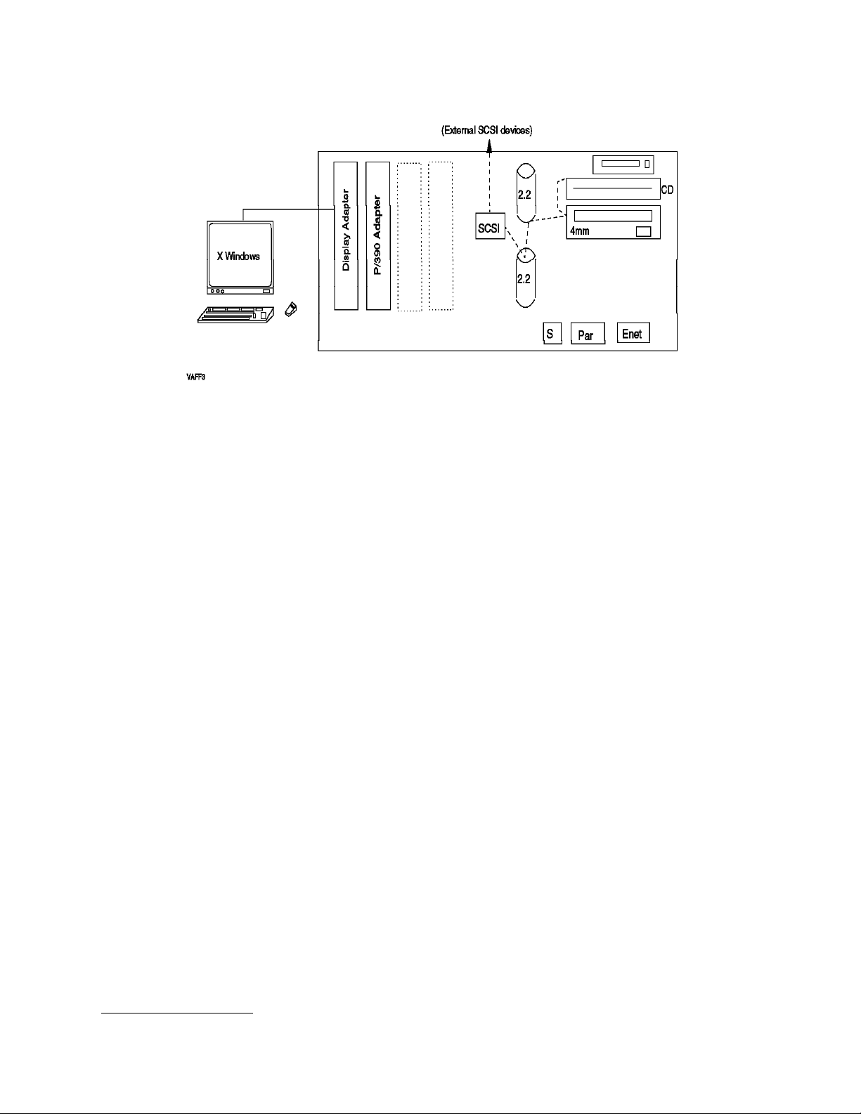
Figure 5. Basic RISC/6000 S/390 System (Model 7012-390)
1.4.1 RISC/6000 S/390 (Model 7012-390)
This system is based on the desk-top model 390.16 The basic configuration is
indicated in Figure 5. Key characteristics are:
•
67 MHz POWER2 processor
•
32 MB memory standard, with 512 MB maximum
•
80 MB/sec Micro Channel, with four slots
•
Integrated SCSI-2 dual-port fast/wide adapter
•
Integrated Ethernet adapter
•
Two internal disk bays
•
CD-ROM drive
•
4mm tape drive (optional, but required for R/390)
A display must be ordered for the system. We recommend a 17-inch unit with at
least 768x1024 or 1024x1024 resolution. Normal R/390 utilization will involve
several 3270-emulation windows (under X Windows) and a smaller screen, or
one with less resolution will impact usability.
This system, the RISC/6000-390 S/390, is not recommended for use with OS/390.
The configuration shown does not have sufficient S/390 storage (there is only the
32 MB on the P/390 adapter) or disk space for OS/390. This system is intended
for use with VM or VSE. It could be upgraded to run OS/390, by adding the S/390
96 MB storage daughter card, and by changing the disks to larger ones or by
adding external disks. This would tend to create a “maxed out” system suitable
only as an entry-level OS/390 platform.
16
The presence of the characters “390” in the base RISC model name is just a coincidence. The 7012-390 systems were in use
before the S/390 adapter and functions were added to it.
Chapter 1. Product Descriptions
13
Page 24

1.4.2 RISC/6000 S/390 (Model 7013-591)
This is a larger system, with more adapter slots and more disk bays. A general
outline is shown in Figure 10 on page 30. Characteristics include:
•
77 MHz POWER2 processor, with 256KB data cache
•
64 MB memory standard, with 2 GB maximum
•
80 MB/sec Micro Channel, with eight slots
•
Integrated SCSI adapter
•
SCSI-2 dual-port fast/wide adapter (uses one MC slot)
•
Six internal disk bays (3.5 inch, half high)
•
CD-ROM drive
•
Standard display adapter
•
4mm tape drive (optional, but required for R/390)
A display must be ordered, and the same considerations apply as for the
7012-390.
1.5 Support Programs
The P/390 adapter is useless without the P/390 support programs, which are
usually delivered on a set of diskettes. (There are two sets of diskettes: one for
the PC Server and one for RISC/6000 Servers.) A number of components are
included:
•
The channel emulator, already mentioned, and a number of programs
involved in interrupt handling and routing
•
A considerable number of device managers
•
Configurator programs, support programs, and tables
•
Microcode for the P/390 adapter, and a program to load it
•
Operator functions for the P/390 adapter
•
Window functions and icons for OS/2 or AIX
•
Documentation files for the various device managers, and one or more
READ.ME files
•
Trace tools
•
Various other utility functions, which typically operate as OS/2 or AIX
commands.
14 P/390 MVS
The use of many of the support programs is centered around the
program
. This is the program that defines the mapping of OS/390 devices (a
configuration
3380 volume, for example) to the device managers and files used under OS/2 or
AIX to emulate the devices. You will frequently use this program while setting
up your system, and installing OS/390. This program is also used for systems
running VM and VSE; some of the functions are specific to those operating
systems. Use of the configurator is described in more detail in 2.6, “The P/390
Configurator” on page 36.
Another key support area provides console (IPL, stop/start, reset, storage
display, and so forth) functions for the S/390 processor. (These functions are
Page 25

provided through the “Manual Operations” icon in the “P/390” window.) Some
of these functions are described in more detail in 5.1, “S/390 Manual
Operations” on page 121.
The device managers are used to emulate various mainframe I/O devices. The
device managers that are relevant to OS/390 are discussed, in detail, in
Chapter 4, “Device Managers and Commands” on page 69.
Device Manager Names
For the P/390 system, most device managers have names beginning with the
letters AWS, although a few have other names. For the R/390, there is more
variation in the device manager names. The following tables always show the
P/390 name, followed by the R/390 name in parenthesis, if it is different. The
R/390 configurator panel, described in detail later, uses the same names as the
P/390. Internally, it then translates these names to the appropriate R/390 module
names. For this reason, we almost always refer to the P/390 device manager
names throughout this document. The only time you, as a system administrator,
would see the R/390 module names is if you list the contents of the directory
containing the modules or if you edit the R/390 IPL or STOP scripts.
Do not assume that R/390 and P/390 device managers have exactly the same
characteristics because they have the same names.
In some cases the equivalent
P/390 and R/390 device managers are essentially the same code (within the
limits of porting between OS/2 and AIX), but in other cases the underlying code
is totally different. Briefly, the device managers include:
•
AWSCKD (dmckd) - CKD DASD emulator, used to emulate 3380, 3390, 9345,
3375, 3350, and 3330 disk drives.
•
AWSFBA (dasd) - FBA DASD emulator for 3370, 3310, 0671-4, 9332, 9335,
9336-10, FB-512 devices.
•
AWSC370 (dmhuron) - S/370 channel adapter manager, used with the S/370
Channel Adapter/A card to attach “real” control units and devices. Only a
limited set of control units and devices are usable through this attachment.
•
AWSTAPE (dmtape) - 3803 3420/3422 emulator, which uses Server files for
tape volumes.
•
SCSI3420 (dm34xx) - uses 4mm or other SCSI-attached tape drives to
emulate an IBM 3420 drive.
•
SCSI3480 (dm34xx) - uses 4mm or other SCSI-attached tape drives to
emulate an IBM 3480 drive.
•
AWS3420 - is a second copy of the SCSI3420 device manager, permitting the
use of a second SCSI-attached tape drive as a 3420 device.
•
AWS3480 - is a second copy of the SCSI3480 device manager, permitting the
use of a second SCSI-attached tape drive as a 3480 device.
•
AWS2821 (printer) - Printer emulator, which emulates an IBM 2821/1403
printer, with output directed to a Server file or to a printer port.
•
AWS2540 (dm2540) - Card reader emulator, uses Server files to emulate
input from a card reader.
17
17
The R/390 module names are different for backward compatibility with a previous system. The module names may be
changed in a later release to match the P/390 names.
Chapter 1. Product Descriptions
15
Page 26

•
AWS3215 (dm3215) - Console keyboard emulator, used to emulate an IBM
3215 typewriter/keyboard. Some stand-alone utility functions (S/390) may
require this, and it can be used by VM.)
•
AWS3274 (dm3270) - IBM 3274 (non-SNA) control unit emulator, which
provides several 3270 sessions on the Server display terminal. For P/390, it
uses a special interface from CM/2. For R/390, it uses TCP/IP tn3270
sessions.
•
LAN3172 (dm3172) - IBM 3172 LAN gateway (SNA), provides an SNA gateway
for external OS/2, DOS, and Windows systems (usually with 3270 emulation
programs) to communicate with OS/390. It can also be used for SNA
connections to a mainframe or to other SNA devices such as printers.
LAN3172 replaces an older device manager, AWS3172. References to
AWS3172 are automatically mapped to LAN3172.
•
WAN3172 - Provides SDLC connections for VTAM
•
LAN3088 - IBM 3088 CTC emulation over a LAN, used only between multiple
P/390 (OS/390, VM, or VSE) systems. (Not available for R/390.)
•
AWSICA (sdlcdm) - Integrated Communications Adapter (ICA) support for
SDLC (not with OS/390) and BSC.
•
AWSPBS - Provides BSC and SDLC links using Portmaster adapters
•
LAN3274 - Permits LAN (non-SNA) 3270 emulation sessions, using a simple
(NetBios or TCP/IP) protocol. These sessions appear as local
(coax-attached) 3270 units to OS/390. LAN3274 does not exist for R/390,
where AWS3274 provides similar functions.
•
LCS3172 (lcs3172tx, lcs3172rx) - Provides an interface similar to a IBM 3172
Channel Station for TCP/IP interfaces.
•
MGR3172 - Provides NetView connectivity to emulated 3172 devices running
LAN3172 or WAN3172.
•
AWSTFA - Transparent File Access (for VM). This permits a P/390 VM user
to link and access a mainframe VM minidisk.
•
AWS5080 - Provides 5088-like functions using FSLA or MSLA adapters.
•
AWS2703 (dm2703) - IBM 2703 communications controller emulator, uses the
Server′s serial (COM) ports to emulate asynchronous ports on an IBM 2703,
for connections (via modems) to ASCII terminal devices. (The 2703 is no
longer supported by OS/390.)
•
AWSOMA - Reads a CD-ROM in OMA format. To OS/390, this appears as a
3420 or 3422 tape drive.
•
AWSPCSRV - Uses P/390 VM users to work directly with Server (OS/2 or AIX)
files.
There are a considerable number of device managers; the following table may
help catorgize them:
Table 1 (Page 1 of 2). Device Manager Utilization
Manager Description OS/390 VM VSE P/390 R/390
AWSCKD (dmckd) CKD DASD Y NR NR YY
AWSFBA (dasd) FBA DASD N Y Y YY
AWSC370 (dmhuron) Bus & tag channel Y Y Y YY
16 P/390 MVS
Page 27

Table 1 (Page 2 of 2). Device Manager Utilization
AWSTAPE (dmtape) pseudo tape drive Y(1) Y Y YY
SCSI3480 (dm34xx) SCSI-attached tape Y Y Y YY
SCSI3420 (dm34xx) SCSI-attached tape Y Y Y YY
AWS34x0 SCSI-attached tape (2) Y Y Y YY
AWS2821 (printer) 1403 pr i n t e r s Y Y Y YY
AWS2540 (dm2540) Emulated card reader Y Y Y YY
AWS3215 (dm3215) Typewriter console NR(3) Y Y YY
AWS3274 local 3270s via CM/2 Y Y Y YN
AWS3274 (dm3270) local 3270s via TCP/IP Y Y Y NY
LAN3172 (dm3172) SNA over LAN Y Y Y YY
WAN3172 SDLC connections Y N N YY
AWSICA (sdlcdm) SDLC, BSC N(4) Y Y YY
AWSPBS BSC, SDLC N(4) Y Y YY
AWSX25 X.25 N(4) Y Y NY
LAN3274 NetBIOS and TCP/IP 3270s Y Y Y YN
LCS3172 (lcs3172tx,
lcs3172rx)
MGR3172 NetView Y N N YN
LAN3088 LAN as CTC Y Y Y YN
AWSTFA VM file access N Y Y YN
AWS5080 5080 displays N Y N YN
AWS2703 (dm2703) S/S terminals N Y ? Y?
AWSOMA pseudo tape drive Y(5) Y Y YY
AWSPCSRV Access Server files N Y N YY
TCP/IP on 390 OS Y Y Y YY
Table notes: NR means not recommended. (1) AWSTAPE does not implement
read backwards commands that are sometimes used by OS/390 standard label
processing. (2) AWS3420 and AWS3480 are second copies of SCSI3420 and
SCSI3480, permitting two drives of each type to be used. (3) AWS3215 is not
recommended for the OS/390 console, but it can be useful for standalone
utilities. (4) AWSICA and AWSPBS cannot be used with OS/390 VTAM; they can
be used with non-VTAM BSC programs, such as JES2 NJE/RJE, although this is
not formally supported. (5) The OMA format is not used for any OS/390 program
distributions by IBM.
The multiple communications-oriented device managers can be confusing. The
following table may help position them.
Table 2 (Page 1 of 2). Communications Device Managers
Manager Use OS/390 VM VSE
AWS3274
(P/390)
3270s on Server display, only. For OS/390
console and a few TSO and/or CICS sessions.
Appears as local, coax-attached 3270s to
OS/390.
Y YY
Chapter 1. Product Descriptions 17
Page 28

Table 2 (Page 2 of 2). Communications Device Managers
AWS3274
(R/390)
LAN3274
(P/390 only)
LAN3172 Full LAN SNA. Appears as CTC-attached 3172.
WAN3172 SDLC connections. Appears to VTAM as
AWSICA Emulate ICA (1-2 lines). Not supported by
AWSPBS Emulate ICA (more lines). Not supported by
LCS3172 Full TCP/IP on LAN. Appears as CTC-attached
MGR3172
(P/390 only)
AWS2703 Not supported by OS/390. Sometimes used for
3270s sessions through TCP/IP (on the Server)
and tn3270-type emulators. Used for the MVS
master console, TSO, CICS, and so forth. Users
can connect through any TCP/IP path. Appears
as local, coax-attached 3270s to OS/390.
Two connection modes: NetBios and TCP/IP (on
the server). NetBios is for OS/2 CM/2 users on
the local LAN, and is very simple to set up.
TCP/IP is for any tn3270-type emulator. Both
modes appear as local, coax-attached 3270s.
Full VTAM definitions required. Can use SNA
3270 emulators, NJE, or any other SNA LAN
connection.
CTC-attached 3172 with LAN-like connections.
WAN3172 translates real SDLC SNA connections
to LAN SNA connections.
OS/390 VTAM. Can be used (VM, VSE) for SDLC
or BSC lines.
OS/390 VTAM. Can be used (VM, VSE) for SDLC
or BSC lines.
3172, using two CTC addresses. Provides
connection to OS/390 TCP/IP.
Connect to NetView, and associated with VTAM
resources defined for LAN3172 and WAN3172
device managers.
dial-in ports to VM.
Y YY
Y YY
Y YY
Y NN
N YY
N YY
Y YY
Y YN
N YY
1.6 Adapters and Connections
A number of optional adapters can be used with the systems. The important
ones are:
•
The S/370 Channel Emulator/A adapter provides a parallel channel (“bus and
tag”) connection between Servers and mainframe control units. Only a
limited range of control units have been used with this connection. Please
see 4.7.1, “AWSC370 Device Manager” on page 106 for more detail. The
same adapter is used with both P/390 and R/390 systems.
•
Token-ring and Ethernet adapters are supported for emulating an IBM 3172
Channel Station. The (emulated) 3172 can be used in a number of ways, and
can provide the primary connectivity link between an OS/390 system and
other systems.
•
Portmaster adapters provide up to eight SDLC (or BSC, in some cases) lines.
Two of these adapters may be used.
•
Wide Area Connector (WAC) adapters are used to emulate the integrated
communication adapters (ICAs) found with IBM 9221 and 9370 systems.
18 P/390 MVS
Page 29

OS/390 does not generally support these devices through VTAM, but bisync
(non-VTAM) can be used with these adapters. These are not used with
R/390 systems. (The PS/2 Multiprotocol Adapter is no longer supported, and
has been replaced by the WAC.)
•
A 4mm tape drive (standard with the system) is used (via a driver program)
to emulate an IBM 3420 or 3480 tape drive.
•
A CD-ROM drive (standard with the system) is normally used for installing
OS/2 programs. In principle, it should be possible to use it to hold read-only
emulated 3380 disks (or read-only emulated 3420/3422 tape files), but we did
not try this function. The CD-ROM can also be used through the OMA
(Optical Media Attach) device manager.
•
A SCSI-attached 3480 or 3490 type tape system can be used (with the
appropriate driver) as a 3480 tape system (supported by OS/390).
•
A SCSI-attached 3420 type tape system can be used (with the appropriate
driver) as a 3420 tape system (supported by OS/390).
•
A number of different disk drives can be used with the systems.
1.7 OS/390 on CD-ROM
IBM has available two different CD-ROM sets for OS/390. One is known as the
Preconfigured System
Application Developers
products included with the systems.
, and the other is the
Partners in Development
or
version. The difference is in the number of program
OS/390, and all the auxiliary program products that are used with it, are
program products
. You must pay the required license fees to obtain and use the
licensed
products. Other things being equal, a system with more program products will
have higher total license fees than a smaller system. Some program products,
from IBM and other vendors, have special license fees for P/390 systems. These
are often known as ESL (Entry System Level) prices. In cases where such prices
do not exist, a P/390 (meaning both PC Server and RISC/6000 versions) will use
the lowest tier price for the software product.
You are not required to use either of the CD-ROM OS/390 systems. However,
you are required to have a proper license for any licensed software you install
on your P/390 system. Note that this is a license for the software
P/390.
An existing license for another processor may not be acceptable, unless
for use on the
it is in the nature of a site license. After making the required license
arrangements, you could use your existing MVS software, order new OS/390 (or
MVS) software, purchase a custom-built (or express-built) OS/390 system from
IBM, order the preconfigured CD-ROM, or use some other path to obtain your
operating system and associated program products.
The Preconfigured System CD-ROM contains a basic OS/390 system, with no
18
additional program products.
It is usable, as is, but would normally be used as
a base for adding additional software products. The Open Edition functions are
not usable because they require RACF (an additional product) or equivalent.
18
OS/390 incorporates the base MVS control program, JES2, OpenEdition, DFSMS/MVS, TCP/IP, SMP/E, TIOC, TSO/E, VTAM, LE,
ISPF, HLASM, DFSMSdfp, and a number of other products. These produce a minimal, usable system. Key functions not
included are RACF, SDSF, and PSF.
Chapter 1. Product Descriptions
19
Page 30

IBM provides special P/390 support and terms for bona fide OS/390 (or VM or
VSE) software developers. This is through the S/390
group (previously known as the
information is available by telephoning 1-800-627-8363 or 1-404-835-9900 (in North
America), or 49-7031-16-2809 in Europe. I n other locations, please ask your IBM
representative for information.
A special OS/390 CD-ROM is available for members of this association. At the
time this was written, the Application Developers′ CD-ROM contained the base
OS/390 system, plus RACF, COBOL, C, Fortran, CICS, DB2, IMS, PSF, and a
substantial list of other products.
The Preconfigured OS/390 CD-ROM has a subset of the addresses generated for
the Developers′ Association CD-ROM. The full set of addresses is listed here,
and all the examples in this document (and other redbooks) use these
addresses. The addresses are:
S/390 Developers′ Association
Partners in Development
). More
S/390 Addresses Device Type
00C 2540R
00E 1403
00F 3203-5
010 3270-X (These two 3270 devices are relics of
063 3270-X the system used to built the CD-ROMs)
120-15F 3380
240-25F 3380 (Reduced from 200-25F range)
260-27F 3390 (Added for OS/390 AD CD-ROM)
560-57F 3480
580-5AF 3400 (Range extended to 5AF)
5A0-5AF 3422
700 3270 (OS/390 console)
700-73F 3277
900-91F 3277
A80-ABF 3390
E20-E27 CTC
E40-E47 CTC
After installing OS/390 from the CD-ROMs, you can change or add to these
addresses by using HCD in the normal manner.
1.8 Positioning and Usage
Experienced MVS customers will naturally compare P/390 and R/390 systems
with their mainframes. While the P/390-based systems use “real” mainframe
software, OS/390 and a large variety of subsystems and applications, they should
not be considered mainframes. Some differences are:
•
IBM mainframes have many layers of (hardware) recovery functions, some of
which (in newer systems) are very sophisticated. Major mainframes have
multiple processors, and transparent recovery mechanisms operate across
the complete complex.
•
The Servers uses small-system disks (and the P/390 support programs do
the necessary functions to emulate mainframe disks).
•
Mainframe channels and control units use intricate webs of multiple paths to
devices, and devices shared with multiple processors. In later mainframes,
this all takes place at a level below the operating system. This sharing of
devices has become a fundamental design element of production
installations.
20 P/390 MVS
Page 31

•
Modern mainframes can be partitioned into multiple systems. This is often
important for supporting production, development, and testing on the same
mainframe. It is also important for software license management.
Who needs P/390 OS/390 or R/390 OS/390? A t the time this was written, P/390
MVS had been available for one year. The range of uses has been surprising;
perhaps the most interesting being a large number of UNIX software developers
who want to port their products to OS/390. Potential users of P/390 OS/390
include:
•
Developers (programming, testing, and so forth)
•
Packaged, turn-key “solutions”
•
Distributed (departmental) production operations
•
“Old Iron” replacement production operations
•
Other, more specialized uses
These categories have implications. For example, a development system may
be a fairly minimal system, in terms of storage and DASD. It may have LAN
connections (for emulated 3270 terminals), but is likely to have no
channel-attached devices. It will probably have a current OS/390 system. It may
have subsystems, such as DB2 and CICS, but in minimal configurations. Many of
the comments in this document are oriented to this type of usage.
A distributed production system is likely to have substantial DASD (for
production data), and may have channel-attached devices (especially 38xx
printers, 3174 controllers, and so forth). By implication, the OS/390 or MVS
system and most program products will be relatively current and may have been
ordered/customized just for the smaller system. The system may have a small
37x5 communications controller for remote mainframe attachment, and/or
SNA-attached 3172 controllers. It is very likely running CICS and DB2. (Both
3172s and 3174s can be emulated, using LAN functions, so the “real” devices
may not be needed.)
An “old iron” replacement system may have a substantial number of internal
disks (since mainframe DASD cannot be attached through the current channel
adapter). It will have channel-attached devices (through the S/370 Channel
Adapter/A), and these are likely to be rather old devices (card readers, punches,
27xx communications controllers, and so forth). The P/390 may be expected to
run the existing level of the old system′s operating system, with few (if any)
changes.
A P/390 OS/390 system is adaptable to many (but not all) of these types of
environments. Limitations are due to (a) not all channel-attached devices can be
used, (b) the I/O bandwidth (and DASD access arm independence) is usually less
than that of a mainframe configuration, (c) meaning that practical paging rates
may be lower, and (d) owners must deal with the Server side of the P/390, as
well as the S/390 environment.
The “other” category is endless. For example, the P/390 could be used to
demonstrate OS/390 products at a trade show. It is certainly easier to transport
and set up than a mainframe, and provides better response times than a remote
link. It could be a test system for the “Year 2000 Problem” by simply setting the
date in the P/390 to a later date than January 1, 2000.
Chapter 1. Product Descriptions 21
Page 32

1.8.1 Selecting a System
We have briefly described three systems:
1. PC Server System/390
2. RISC/6000 S/390 (Model 7012-390)
3. RISC/6000 S/390 (Model 7013-591)
Some thought is needed to select the best base system for your needs. This
discussion assumes you intend to run OS/390; considerations for VM or VSE may
differ.
Key issues are:
•
The 7012-390 is not recommended for OS/390, and is excluded from
consideration. The limited number of internal disk bays and adapter slots
are the key factors involved here.
•
The underlying performance of the 7013-591 processor is better than that of
the current PC Server. This permits the device managers to run faster, and
improves overall performance. (Device manager overhead, especially for
CKD emulation, is often a constraining factor for system performance.)
•
The PC Server offers more expandability, without requiring external boxes.
In practice, it can house 17 disk drives with 2.25 GB per drive.
•
The RISC/6000 systems use AIX as the Server operating system. AIX is
more complex than OS/2, but may offer better dispatching, SMP support, and
more effective use of SCSI disks. However, system administration can be
more complex than with OS/2.
•
The PC Server system uses OS/2 as the Server operating system. OS/2 is
less complex than AIX, and may be easier to administer. However, OS/2
support of SMP hardware is more restricted than that of AIX, limiting
performance growth in this driection.
•
In practice, running substantial OS/2 applications while OS/390 is also active
is not generally advisable. The superior speed and more sophisticated
dispatching function of the AIX systems may permit significant AIX
applications to run in parallel with OS/390. However, at the time this was
written, we were unable to quantify this.
•
More device managers, more mature (better tested), are available for the PC
Server system. This advantage will change over time, of course.
•
The PC Server system costs less than the RISC/6000-based system.
19
19
This is true at the time this was written. Disk products offer increased capacity at frequent intervals, and larger drives, in the
one-inch height that best suits this Server, may become available soon.
22 P/390 MVS
Page 33

Chapter 2. Configurations and the P/390 Configurator
This chapter describes several typical PC Server System/390 configurations, and
several RISC/6000 S/390 configurations, with emphasis on adapters required and
adapter slots used. There are many potential configurations possible, and the
ones described are merely representative samples.
A later part of this chapter describes the P/390 configurator function. This
configurator, in direct and indirect ways, contains parameters related to the
Server configuration, and also to the OS/390 I/O definitions.
PC Server System/390 configurations are described in more detail, because we
have had more experience with these configurations. At the time this was
written, the RISC/6000 S/390 systems were new and we had much less
experience with possible configurations.
2.1 Server Workload Considerations (P/390)
Experience has shown us that, if the S/390 portion is heavily loaded, there is
little processing capacity left on the OS/2 side of a PC Server System/390,
although the PC Server 520 may improve this situation. One reason we assume
the OS/2 side is generally busy when running OS/390 on the S/390 side is that
CKD disk emulation, always required by OS/390, presents a heavy workload for
OS/2.
Furthermore, we have found that high utilization on the OS/2 side sometimes
delays emulated DASD response to the point where OS/390 goes into error
recovery, thinking that a disk I/O operation has failed. Once OS/390 begins disk
error recovery, the emulation process can fail, bringing down the whole P/390
subsystem. One of the reasons is that complex CCWs associated only with error
recovery are not fully emulated -- the assumption being that all “real” error
recovery is performed under OS/2 by the relevant device manager. We have
encountered such situations, even with fairly light OS/390 loads. OS/390 expects
certain timing responses from its channels (remember that OS/390 has no
special code for P/390 systems -- it assumes it is running with real hardware
channels and control units), regardless of the OS/390 workload present.
For these reasons we recommend that you do not plan to run a heavy workload
on OS/2 while OS/390 is running. The situation with VM or VSE is different.
They normally use FBA disk emulation, which requires much less OS/2
processing, and a parallel workload on OS/2 (such as LAN Server functions) may
be feasable.
The situation may be different with RISC/6000 S/390, for two reasons: the
20
processors are faster
, and AIX has a more flexible dispatching mechanism.
20
This means that the effective integer processing speed is faster; this is not necessarily related to comparative processor clock
speeds.
Copyright IBM Corp. 1996 23
Page 34

Figure 6. Basic PC Server System/390 Unit. A PC Server 520 is the base unit.
2.2 PC Server System/390 Configurations
Any PC Server System/390 system requires OS/2 as the Server operating
system. Additional program products, such as CM/2 (or TCP/IP with a telnet
3270 option, or a future version of PC/3270) are needed. The P/390 support
programs and files are always needed. OS/2 and the other programs require
disk space. We generally allocate 200 - 250 MB for this purpose. Our most
common allocation (in the sense of partitioning disks) is to create a 250 MB “C”
drive (for OS/2, CM/2, and so forth), and (assuming a RAID system), a very large
“D” drive for the P/390 support programs and emulated 3380 and 3390 volumes.
This allocation for C is larger than required, and allows a comfortable amount of
free space.
Figure 6 illustrates the basic configuration of a PC Server System/390 for use
with OS/390. It contains a RAID adapter and five 2.25 GB disk drives. The RAID
adapter (operating in RAID-5 mode) effectively removes the space equivalent of
one drive
(and the 4mm tape drive and the CD-ROM drive), and the other two are unused
in this configuration. The top disk bay will accept only five drives, because the
SCSI address normally used for the sixth drive has been used for the 4mm tape
drive. (Newer systems may use the internal SCSI adapter for the CD-ROM and
4mm drives, removing this restriction.)
21
The RAID adapter has three SCSI channels; one goes to the disks
The 2.25 GB disk drives, indicated in the illustration, are the standard units at the
time this was written. Lower capacity drives should not be considered for use
with OS/390. Larger capacity drives can be used, although there was not a
21
.This space is used to store redundant data that permits RAID to survive the loss of any one disk drive.
24 P/390 MVS
Page 35

Figure 7. PC Server System/390 Configured for Additional Disks. A PC Server 520 is the base unit.
standard larger one-inch high drive available at the time this was written. A ll
the disk drives in a RAID array should be the same size. If they are not, then all
are treated as though they were the size of the smallest unit.
Figure 8. PC Server System/390 With Channel-Attached Devices. A PC Server 520 is the base unit.
Chapter 2. Configurations and the P/390 Configurator 25
Page 36

Figure 9. PC Server System/390 With Sixteen SDLC Lines. A PC Server 520 is the base unit.
A system ordered for OS/390 will always include 128 MB of S/390 storage. This
currently requires two adapter slots, one for the P/390 adapter and one to
provide space and power for the additional storage daughter card.
An adequate SVGA adapter is built on the planar, and no slot is required for it.
The standard PC Server System/390 has 32 MB memory (on the Pentium or OS/2
side), and this has proven to be sufficient. We do not recommend adding
additional memory, unless you have specific OS/2-side requirements for it.
Figure 7 illustrates a larger PC Server System/390, with emphasis on availability.
All three RAID channels are used, and each channel is defined as an array.
HS
Each array has a hot-standby disk, noted by the
A hot-standby disk normally contains no data. If a data drive in the RAID array
fails, the RAID controller will immediately (without operator intervention) rebuild
the data from the failed disk on the hot-standby disk. The hot-standby disk does
not replace the “extra” disk required by a RAID 5 array for storing redundant
data. Thus, in the top bay in the illustration, the effective disk capacity is 3 x 2.25
GB; in effect, the fourth drive is for redundant data and the fifth drive is for the
hot-standby unit.
This design requires a number of extra disk drives, but provides two levels of
automatic failure recovery. Since the system is configured for high availability,
an external UPS (uninterruptable power supply) is shown.
symbol in the illustration.
26 P/390 MVS
This example includes an external SCSI-attached 3480- or 3490-type tape drive,
permitting tape exchange with mainframes. Such tape drives are frequently
used with PC Server/390 and RISC/6000 S/390 systems. Tape drives are
Page 37

discussed in more detail in 2.5, “Tape Configurations” on page 34. An Ethernet
LAN adapter is shown, and would probably be used to connect to workstations
running 3270 emulators. Two SDLC lines are shown, for wide-area connectivity.
This example also includes a PC laser printer. One of the device managers,
AWS2821, can be configured to provide excellent OS/390 output using this
device. It is also possible to drive it through PSF and PSF/2; this is discussed in
detail in
Printing with MVS on the IBM PC Server System/390
, order number
SG24-4612.
Figure 8 illustrates a system with emphasis on connections to mainframe control
units. In this case, two parallel channels are used, and a 3174 control unit (for
3270 terminals), a large 3900 AFP printer, and 3480 tape drives are shown. Other
control units can be used; there were selected for illustration and because they
are typical of the devices that might be considered for use with P/390 OS/390.
The parallel channels are provided by the S/370 Channel Emulator/A adapters.
A maximum of two of these can be used. Multiple control units can be chained
on each of these channels, although the number of control units and the total
length of the cables used are somewhat more restrictive than with mainframe
channels. Mainframe disk drives cannot be attached through these channels.
See 4.7.1, “AWSC370 Device Manager” on page 106 for considerations about
using these channels.
This illustration also reinforces the message that the basic PC Server disk
configuration, with five 2.25 GB drives, can be adequate for OS/390 operation.
Figure 9 illustrates a system with emphasis on SDLC communications. It has
two PortMaster adapters, each of which can provide eight SDLC lines. A S/370
channel adapter is included. It is shown attached to a 3745 communications
controller, but the channel could also continue to includes printers or other
channel devices.
Two disks are attached to the internal SCSI adapter, and are not part of a RAID
array. This was done because the disks are different sizes than those in the
RAID array. Disks in a RAID array should all be the same size; there is no
restriction about sizes attached to a simple SCSI controller. In the system
shown, some disks (in the RAID array) have higher availability than other disks
(attached to the simple SCSI adapter). The user would probably place
non-critical emulated OS/390 volumes on the SCSI-adapter disks: scratch
volumes, paging volumes, perhaps JES2 spool, and so forth.
How many disks (or how much disk space) should you order for your P/390
OS/390 system? This is obviously an open question. How much data do you
want to put on the disks? How many DASD volumes do you want to emulate?
Do you have enough physical disk arms for your OS/390 workload? Here are a
few considerations that may help your planning:
•
If you will use an array model of the system (that is, a RAID model), try to
order enough disks in advance. Extending a RAID array (adding additional
disks) requires you to redefine the array, and with some RAID adapters you
lose all the data in the process. (You would take a backup first, of course,
but this may take some time for a large disk array.)
•
You can add disks to an array model, and define a new array to use the new
disks. This will avoid the problem of saving and restoring all your disk data,
Chapter 2. Configurations and the P/390 Configurator 27
Page 38

but you will now have multiple disks (as seen by OS/2) because each array
is seen as a (large) OS/2 disk.
•
It is possible to have a one-disk array (using RAID 0). This is not common,
but might be needed when extending a configuration.
•
The RAID SCSI adapter cannot be used to attach disk drives that are not part
of an array. It can be used to attach non-disk SCSI devices (which are not
part of an array, of course). The RAID adapter has an external connector
that can be used for disks (in a RAID array) or non-disk devices. This
external connector parallels one of the internal connectors; you can use the
internal disk path, or the external connector, but not both. There is a
maximum of seven devices per channel.
•
It is possible to have both RAID and non-RAID SCSI adapters in the same
server.
•
All disks attached to a RAID SCSI adapter should be the same size. If they
are not, all will be used as though they were the size of the smallest disk.
For example, if you have four 2GB disks and one 1GB disk, the RAID adapter
will treat them as five 1GB units (if they are all defined into the same array).
•
Other things being equal, a non-RAID disk may be faster but may exhibit
slightly lower reliability. RAID (meaning RAID 5, the mode that is usually
used) always requires access to two disks for a write operation (including
OS/390 paging and spooling, of course). Trying to generalize about RAID
versus non-RAID performance is difficult. In some cases, RAID might be
faster due to the automatic spreading out of files across all disks in an array.
•
The system normally requires the use of special “hot swap” holders
(“trays”) for disks. (Disks purchased with the system are already mounted in
these trays.) It can use several different models of disks, but all must be
22
mounted in these trays.
You can buy empty trays and mount your own
disks. There are two models of trays, for “narrow” 8-bit disks and for “wide”
16-bit disks.
Server (see the announcement marketing materials).
Be certain your disks are among those supported by the PC
The disk connectors
must match the connectors in the appropriate tray. Order empty trays at the
same time the system is ordered.
•
The system has three shelves (bays) for disk drives. The first bay can
accept five or six one-inch disks. (One slot may be lost “lost” to the 4mm
tape drive SCSI interface.) If half-high disks are used, only three will fit in
the bay. The second and third bays will each accept six one-inch disks, or
three half-high disks, or a mixture.
•
To use the second and third bays you must add one additional power supply,
one (or two) backplane kits. (Read the information supplied with your IBM
PC Server System for specific information about upgrades. Some models
may have one extra backplane and the extra power supply already installed.)
•
The 1.12GB and 2.25GB disk drives marketed with the IBM PC Server are
one-inch units. The 4.5GB drive is half-high. Slightly older disks (1GB and
2GB) are usually half-high.
23
22
Once you acquire or convert disks using the hot-swap trays, you will find they are convenient and easy to use. They permit
the installation of a large number of disks in a modest space.
23
The author′s unit has one one-inch 1GB drive and two half-high 2GB units on the first shelf. No additional drives will fit in that
bay.
28 P/390 MVS
Page 39

•
If the first bay holds five 2.25GB drives, this provides 11.25 GB total space;
using three 4.5GB drives provides 13.5GB total space. Ignoring price, five
disks may be better than three disks because there is more freedom of disk
arm movement. Use of RAID will change this storage discussion, of course.
The numbers uses here are for non-RAID models. With RAID 5, you will lose
the equivalent capacity of one physical drive for each RAID 5 array. In this
case, you are left with 9GB effective space for either 5x2.25 GB or 3x4.5 GB
configurations. Using six 2.25 GB drives, with RAID 5, provides the maximum
effective disk space.
•
The Application Developer′s CD-ROM OS/390 Release 1 system requires the
following space:
1. 2.8 GB for the OS/390 IPL volume (3390)
2. 2.8 GB for a DLIB volume (3390) (if you decide to install the DLIBs)
3. .2 GB for an SMS-managed volume for HFS files (mini-3380)
4. 1.2 GB for the volume containing paging, spooling, catalog, PARMLIB,
and so forth (3380)
5. 1.2 GB for CICS, DB2, IMS (3380) (if you decide to install this volume
6. Perhaps .8 GB for TSO and scratch volumes (mini-3380). These are not
included with the CD-ROM, but you are likely to want to create them.
This is 9GB, or 5GB if you do not install the DLIB and DB volumes. You can
have a reasonable, basic OS/390 system by filling the first disk shelf with
2.25GB drives.
2.3 RISC/6000-591 S/390 Configurations
An R/390 system requires disk space for AIX, the P/390 support programs, other
programs (such as 3270 emulators), and the emulated S/390 volumes. AIX
partitions disks by using logical volumes and multiple file systems.
Approximately 400-500 MB is required for base AIX (including normal workspace
for /tmp and similar files). See 3.3, “RISC/6000 S/390 OS/390 Installation” on
page 50 for more information about suggested disk layouts.
Figure 10 on page 30 illustrates the basic RISC/6000-591 S/390 configuration.
This base system has four disk drives, with 2.2 GB each, attached to a SCSI
adapter. A 4mm tape drive (required, for practical OS/390 usage) and a
CD-ROM drive are also connected to the SCSI adapter. The frame can hold a
maximum of six disk drives. A fast/wide SCSI adapter has two channels, and
each channel can control six devices. One of the channels can be attached to
external SCSI devices (in which case that channel cannot be attached to any
internal SCSI devices).
One LAN adapter is shown. Only one TCP/IP “stack” can use a LAN adapter at
any one time. AIX must have a functional TCP/IP system (to provide a telnet
session for OS/390 consoles and TSO users). In this configuration, it would not
be possible to use OS/390 TCP/IP because there is no LAN adapter for it.
This configuration leaves three free Micro Channel slots for future adapters.
This base system includes 64 MB memory, but 128MB is recommended for
optimum S/390 performance. The improvement is due to AIX using the extra
memory as a disk cache. This improves the performance of CKD emulation, and
we have seen up to 30% improvement in selected workloads.
Chapter 2. Configurations and the P/390 Configurator 29
Page 40

Figure 10. RISC/6000-591 S/390 Basic Configuration. There is not a “standard” configuration for a basic OS/390
system. This illustrates an entry configuration that would serve for basic OS/390 usage. The disk drives would
probably be 2.25 GB units, although you have a choice of drives. See Chapter 3, “Installation” on page 43 for a
discussion of the amount of disk space needed.
Figure 11 illustrates a larger system. In particular, it uses an external IBM 7137
Disk “Tower,” containing up to eight 2.2 GB drives operated as a RAID array.
These towers use differential SCSI attachments (permitting longer cable lengths),
and require a differential SCSI adapter. A S/370 Channel Adapter/A is also
shown (the same as used with the PC/Server System/390, but with different
driver code).
An external SCSI-attached 3480/3490-type tape drive is attached to the standard
SCSI adapter. This permits direct interchange of tape volumes with most
mainframe systems, and would be a typical device for P/390 and R/390 systems.
See 2.5, “Tape Configurations” on page 34 for more information about external
tape drives.
Two LAN adapters are shown, permitting both AIX and OS/390 to use TCP/IP
connections.
2.4 3270 Connection Configurations - Overview
Any practical OS/390 system requires 3270 terminals -- for the system console,
for TSO users, for CICS control and many CICS applications, and so forth. There
are a number of ways to provide 3270 terminals for P/390s, and these are partly
summarized in Figure 12 on page 32. The R/390 connections are slightly
different, and are described later. Using Figure 12 on page 32,
30 P/390 MVS
Page 41

Figure 11. RISC/6000-591 S/390 Larger Configuration
1. The first method uses AWS3274 and applies only to 3270 sessions in the PC
Server; that is, 3270 windows on the OS/2 display of the PC Server
System/390. The
coax UCBs
methods) means that OS/390 views these terminals as being coax connected
through a channel-attached non-SNA 3174 control unit. This is the most
basic method of attaching 3270 terminals, and is often used for OS/390
consoles. CM/2 recognizes a
3270 data streams through an API that talks with the AWS3274 device
manager.
The 3270 emulator functions that use this connection are being
withdrawn from CM/2. The P/390 developers intend to use the same
connection mode with a future change to PC3270.
for providing several 3270 sessions for OS/390. OS/390 must have a UCB for
each terminal, and the P/390 configurator must have a line for each terminal.
(Each 3270 emulator window is a “terminal.”)
2. The LAN3274 device manager accepts TCP/IP connections, and emulates
coax-connected3270 terminals. The TCP/IP connection uses 3270 telnet
protocols. In order to use this connection, you must install TCP/IP on the
Server.
A given LAN adapter can be used for only one TCP/IP product. You
cannot have OS/390 TCP/IP and Server TCP/IP use the same LAN adapter
24
Once the Server TCP/IP is installed, you can connect to it from a 3270
port.
emulator in the Server, or from anywhere on the connected LAN. Any
emulator can be used. Again, these emulated 3270 sessions appear as
notation for this method (and several other
LOCAL
attachment mode, in which it passes
This is the easiest method
telnet
24
Some LAN adapters have multiple ports, and different TCP/IP products could be running on different ports.
Chapter 2. Configurations and the P/390 Configurator 31
Page 42

Figure 12. Methods of Connecting 3270 Terminals to the P/390
local, coax-connected terminals to OS/390. An OS/390 UCB and a P/390
configurator line are required for each emulated session.
3. IBM developers have discussed a modification to the PC/3270 product, such
that it can work directly with the AWS3274 device manager -- very much like
the CM/2 connection shown at the top of the figure. This function was not
available, at the time this was written, and was being investigated as time
was available.
4. The P/390 support programs include a modification for CM/2 that produces
the next connection method in the drawing. It assumes workstations with
OS/2 and CM/2 (plus a simple module replacement in CM/2) are connected
32 P/390 MVS
Page 43

Figure 13. Methods of Connecting 3270 Terminals to the R/390. Note that the device manager names shown are
the generic names used in the configurator, not the actual R/390 module names. See 1.5, “Support Programs” on
page 14 for a brief discussion of device manager naming.
to the Server via a local LAN. NetBios is used by the LAN3274 device
manager and the modified CM/2. This connection works only with local
LANs, since NetBios is not routable in complex networks. Again, the
terminals appear to be local, coax-attached terminals to OS/390. OS/390
must have a UCB for each terminal session (a CM/2 user can have up to five
3270 emulator sessions) and there must be a P/390 configurator line for each
3270 terminal (session or window).
This method will soon be obsolete, as the
3270 emulator functions are being withdrawn from new releases of CM/2.
5. The LAN3172 device manager emulates the functions of an IBM 3172 LAN
station used for SNA connections. It is connected to OS/390 through a CTC
(channel-to-channel) interface (also known as a 3088 interface), and is used
through normal VTAM functions. There is one CTC address, regardless of
the number of 3270 sessions connected this way, and only one line in the
P/390 configurator. This device manager uses a Server LAN adapter (token
ring or Ethernet) for general LAN connectivity. It works with SNA 3270
emulators on the LAN. There is no specific limit to the number of sessions
supported, but there must be VTAM definitions for each session. The VTAM
parameters are exactly the same as for a “real” 3172 unit on a mainframe.
The use of the LAN adapter can be shared with other Server programs and
with TCP/IP (but only one TCP/IP).
Chapter 2. Configurations and the P/390 Configurator 33
Page 44

6. The LCS3172 device manager emulates the functions of an IBM 3172 LAN
station used for TCP/IP connections. In this case two CTC addresses are
used, regardless of the number of telnet 3270 sessions involved. Two lines
are required, with consecutive unit addresses, in the P/390 configurator
table. An OS/2 LAN adapter (token ring or Ethernet) is used for external
connections. OS/390 TCP/IP must be installed and operational. This use of
a PC Server LAN adapter is mutually exclusive with any use by the Server
TCP/IP on the same adapter.
7. The next method, using WAN3172, is for remote (via modem) use. A WAC
(Wide Area Connector, two lines, P/390 only) or a PortMaster (eight lines,
P/390 and R/390) adapter is used. The P/390 support programs will accept
dial-in connections, but cannot generate dial-out connections. Leased lines
can be used.
8. The last method shown uses a S/370 Channel Emulator/A adapter, with bus
and tag cable, to connect to a 3174. This, in turn, connects to 3270 terminals
via coax cables. If a non-SNA 3174 is used, there must be one OS/390 UCB
and one P/390 configurator line for each terminal. If an SNA 3174 is used,
there is only one OS/390 UCB and one P/390 configurator line, regardless of
the number of terminals. Experience has shown that SNA 3174 connections,
via the channel emulator, are not reliable, and we do not recommend this
usage.
The 3270 connections for R/390 systems are shown in Figure 13 on page 33
1. In the R/390, the AWS3274 device manager uses a TCP/IP interface to either
local or remote tn3270-type emulators.
2. The LAN3274 device manager does not exist for the R/390.
3. The other device managers have the same functions as for the R/390.
2.5 Tape Configurations
You have several options for using tape drives with P/390 OS/390, as illustrated
in Figure 14 on page 35:
1. Use a channel emulator adapter to connect to a “real” IBM 3480/3490 or IBM
3803 control unit. These control units have multiple channel interfaces. The
channel adapter would represent just another channel attached to the control
unit. Of course, the Server must be within channel-attachment distance to
use this option. This is the least expensive way to use 3480/3490 or 3420
tapes (provided you already have the tape drives, of course). It tends to be
slower than the expected speed of the tape units (due to the current channel
adapter), but performance is still acceptable (unless you have small,
unblocked records on tape). This option has the advantage that the whole
string of tape drives attached to the control unit is available to the OS/390
system. Please read 4.7.1, “AWSC370 Device Manager” on page 106 for
considerations about using channel-attached devices.
2. Purchase one or two SCSI-attached (external) 3480/3490-type tape drive, and
attach them to a SCSI adapter in your system. For the P/390 this requires a
25
25
This is almost the same function provided by one of the LAN3274 options on the P/390, and is the only case in which P/390 and
R/390 device managers with the same name (AWS3274) have different functions on the two systems. The thought was that
AWS3274 should always represent the most basic 3270 connection, as used for the OS/390 console, for example.
34 P/390 MVS
Page 45

Figure 14. Ways to Configure Tape Drives. The device manager names associated with each mode of attachment
are shown in parenthesis.
“single-ended” SCSI adapter in the tape drives.26 IBM does not market this
type of unit. We used tape drives from Overland Data, Fujitsu, and other
vendors. A drive such as this is very convenient because it can interchange
tape cartridges with any host OS/390 system, and has reasonable
performance. These drives are relatively small, and are usually placed on
top of the Server. If you do not have jobs that require more than one or two
tape drives, this is an attractive option. The SCSI3480 device manager is
used for the first such drive, and the AWS3480 device manager is used for
27
the second drive.
The R/390 versions of SCSI3480 and SCSI3420 each
supports more than a single SCSI drive. IBM does market a 3490E drive with
a differential SCSI interface.
3. Purchase a SCSI-attached (external) 3420-type tape drive. The SCSI3420
device manager is used for these drives. A second 3420-type drive can be
emulated with the AWS3420 device manager.
The SCSI3420 device manager can also be used with 3480/3490-type tape
drives, and the SCSI3480 device manager can be used with 3420-type tape
drives. See 4.4, “Device Managers for Tape Drives” on page 82 for more
discussion.
4. Use the 4mm tape drive that is included with your system. Device manager
SCSI3420 or SCSI3480 is used with the unit. Performance is good, but there
26
The RAID adapter in the PC Server System/390 provides an acceptable external SCSI interface. You can use a differential
SCSI tape drive if you purchase a differential SCSI adapter for your system.
27
If you need more than two SCSI-attached 3480/3490 drives, see 4.4.3, “ISITAPE Device Manager (P/390 Only)” on page 89
Chapter 2. Configurations and the P/390 Configurator 35
Page 46

is no compatibility with host systems. There is compatibility with other P/390
OS/390 systems using the same option, of course. Again, there is normally
only one 4mm tape drive with a system. Many IBM products (and service)
are available on 4mm tape, and IBM service will accept dumps on 4mm
tapes.
5. Use emulated tapes, that are emulated using Server files and the AWSTAPE
device manager. This may be suitable for work tapes, or for “tapes” that are
retained for a while.
While performance is poor, the emulated tape can even be on diskette when
using a P/390. A diskette has some obvious limitations, but it may be usable
where tape processing is designed into an application, but the total amount
of data involved) is relatively small.
With the P/390, you can have up to four SCSI tape drives. One (4mm tape) is
included with your system. You can add more; they can be 4mm drive, 9-track
drive, or 3480/3490 type drives. (You can also use 8mm drives with the R/390,
and its SCSI34x0 device manager can support multiple SCSI drives.) There are
four SCSI tape device managers: SCSI3480, AWS3480, SCSI3420, and AWS3420.
Each device manager is used with only one device for the P/390, and this creates
the limit of four SCSI tape drives. Of the four, two can emulate 3480 drives and
two can emulate 3420 drives. The OS/390 UCB (address) associated with each
drive must be the proper device type: 3480 or 3420. Do not use a 3490 UCB; it
will not receive the correct sense codes from the SCSI3480 device manager. If
you need more SCSI-attached tape drives than possible within these limits, see
4.4.3, “ISITAPE Device Manager (P/390 Only)” on page 89.
3480 emulation means that the device manager will respond to the additional
device commands available on these drives. 3420 drives have fewer device
commands. In general, OS/390 application programs can use the two device
types interchangeably. Ignoring questions about data compression, a 4mm tape
written with the SCSI3480 device manager can be read using the SCSI3420
device manager and vice versa.
2.6 The P/390 Configurator
The P/390 Configurator is an OS/2 or AIX program. Its primary purpose is to
maintain a table (stored in a Server file) that connects S/390 device addresses to
P/390 device managers. The basic table might look like this, for a PC Server
System/390 system:
S/390 Address Device Device Manager
120 3380 AWSCKD.EXE
121 3380 AWSCKD.EXE
560 3480 SCSI3480.EXE
700 3270 AWS3274.EXE
701 3270 AWS3274.EXE
A80 3390 AWSCKD.EXE
Using a table such as, if OS/390 issues an I/O instruction (such as SSCH) for
address 120, the P/390 channel emulator will give control to device manager
AWSCKD. The device manager then reads the CCWs from S/390 memory (via
the channel emulator) and emulates 3380 I/O using Server files. If the I/O
operation is for device address 700, the AWS3274 device manager is called to
emulate a 3270 terminal (in a window on the Server′s display). In this example,
36 P/390 MVS
Page 47

note that device manager AWSCKD is used several times, and for different types
of devices. Some device managers can appear multiple times in the
configurator, and some (such as SCSI3480) cannot be used more than once.
The channel and control unit emulation is device-by-device. There is no sense
string
of a
3380, are completely arbitrary. You could have a system with three emulated
3380 drives, at addresses 001, 6AF, and EE3. O f course, your OS/390 must have
UCBs generated (via HCD) at the corresponding addresses. If you have
mainframe devices attached through a S/370 Channel Emulator/A adapter, these
would retain their original string of addresses, if appropriate.
The configuration table is stored in a DEVMAP file. This is a normal Server
(OS/2 or AIX) file. I t can have any name, but the convention is to name it
DEVMAP.xxx, where xxx is used to differentiate between several DEVMAP files.
For example, you might have DEVMAP.MVS, DEVMAP.VSE, DEVMAP.TST, and so
forth. The
current
of disk drives or tape units. The channel addresses, such as 120 for a
current
DEVMAP is changed with the AWSPROF command; for example:
DEVMAP is used, by default, for most P/390 functions. T he
D:> AWSPROF D:\DEVMAP.MVS (make DEVMAP.MVS the current DEVMAP)
D:> AWSPROF (No operand. Will display current DEVMAP name.)
For OS/2, you
directory. For both OS/2 and AIX, you must supply the full path name. The
configurator program (and the IPL process used to start the P/390 subsystem
and OS/390) always use the
reason, you must remember to use the AWSPROF command. The name of the
current DEVMAP is retained across Server startups.
The complete installation process is outlined in Chapter 3, “Installation” on
page 43. Once the P/390 subsystem is installed, you need to access the primary
P/390 window in order to perform most P/390 functions. For OS/2, this is done
by double clicking the P/390 icon on the desktop. For AIX, it is done by starting
X Windows and then entering the command r390 in an AIX window.
must
enter the leading backslash, even if the file is in a root
current
DEVMAP. I f you want to change it for some
Chapter 2. Configurations and the P/390 Configurator 37
Page 48

Figure 15. Base P/390 Window. Practically all P/390 administration starts from this
window. The equivalent window for the R/390 is obtained by entering the command r390
after starting X windows.
┌─────┐
│icon │
└─────┘
P/390
┌──────────────────────────────┐
│ │┌────┐ │
│ ││icon│IPL P/390 │
opens │ │└────┘ │
to │ │┌────┐ │
│ ││icon│End P/390 │
└────────── │└────┘ │
│┌────┐ │
││icon│P/390 Configuration │
│└────┘ │
│┌────┐ │
││icon│P/390 Manual Operations │
│└────┘ │
│┌────┐ │
││icon│P/390 I/O Trace │
│└────┘ │
│┌────┐ │
││icon│P/390 Snap Shot Dump │
│└────┘ │
└──────────────────────────────┘
To use the P/390 configurator, open (double click with OS/2, single click with AIX)
the P/390 Configuration icon. This should produce a “Configuration Password”
panel such as the one shown here:
The configurator system │ Configurator Filenames │
is password protected. │ │
Please type your password │ Device map > D:\DEVMAP.MVS │
and press ENTER. │ DMKRIO.ASM > │
@───────────────────────┐ │ Directory > │
│ PASSWORD>> │ │ │
└───────────────────────┘ └─────────────────────────────────────────┘
┌────────────────────────┐
│ FUNCTION KEYS │
││
│ F1 - Help │
│ F10 - Exit Configurator│
└────────────────────────┘
Figure 16. Configurator Password Panel. Typically, no password is set. Simply press
Enter to proceed to the next screen.
────────────────────────────────────────────┐
│ C O N F I G U R A T O R P A S S W O R D │
└────────────────────────────────────────────
┌─────────────────────────────────────────┐
││
38 P/390 MVS
By default, there is no password. Just press Enter. Before doing this (the first
time you use this panel), check the upper right window, for Configurator
Filenames.
These parameters are for VM, and OS/390 will not work properly if these two
it.
If there is anything in the “DMKRIO.ASM” or “Directory” lines, erase
Page 49

parameters exist. You cannot directly change the “Device map” parameter; you
would need to exit from the P/390 subsystem and use the AWSPROF command
to change it.
You cannot use a normal text editor with the DEVMAP files.
DEVMAP file with a text editor, it will probably not work afterwards. Only the
P/390 configurator program should be used to alter DEVMAP files, and only the
configurator can view a DEVMAP file in a reasonable format. (A utility,
DEV2NAME, also can be used to print a DEVMAP in a reasonable format.)
Changes to DEVMAPs are detected only when the P/390 subsystem is started.
For example, using the IPL icon will start (or restart) the P/390 subsystem and
read the current DEVMAP. Changes made to DEVMAP while OS/390 is running
(or any other S/390 system is running) are not activated until the P/390
subsystem is restarted. This always requires a reIPL for the S/390 operating
system being used.
Press Enter in the password panel. This should produce the next panel:
Press the FUNCTION KEY for the activity you want.
┌─────────────────────────────────┐ ┌───────────────────────────────────┐
│ Major Functions │ │ Description of Major Function │
│F1 Help │ │F2 Allocate new files, delete data │
│F2 Update System Devices │ │ from the system, modify address.│
│F3 Update User Data (VM only) │ │ Update all DEVMAP information. │
│F4 Update System Environment │ │ │
│F5 Change Configurator Password │ │F3 Add/Delete/Change USERIDs, mini │
│F6 END - SAVE ALL, then EXIT │ │ disks, and user links. (VM) │
│F7 Update 3270 LT Sessions │ │ │
│F8 SAVE - SAVE ALL, Do not EXIT │ │F4 Change CPUID, GMT Offset, Cache │
│F9 Display Files Not Found │ │ buffer size, IPL address │
│F10 QUIT - Do not Save Anything │ │ │
│F11 Configure 3172 SDLC Gateway │ │F7 Allocate/Change LT 3270 sessions│
││ │ │
└─────────────────────────────────┘ └───────────────────────────────────┘
┌─────────────────────┐
│ F U N C T I O N S │
└─────────────────────┘
If you alter a
Figure 17. Main Menu of Configuration Program
Function key F2 produces the “Update System Devices” panel where all your
emulated S/390 devices are defined. You will probably update this data many
times, and you should devote some time to understanding this panel. It is the
single most important panel in the P/390 support system. This panel displays
(and alters) data in the
specified with the AWSPROF command. If you install one of the CD-ROM OS/390
systems, following the normal instructions, your initial device map file is
D:\P390\DEVMAP.MVS for OS/2, or /mvs/devmap.mvs for AIX. Your display
should look something like the following:
current
device map file. The
Chapter 2. Configurations and the P/390 Configurator 39
current
device map file is
Page 50

U P D A T E S Y S T E M D E V I C E S
Available disk space in Kbytes: 47,123
@───────────────────────────────────────────────────────────────────────┐
│ Addr Device Label Atype Size Mgr FN/P PATH=D:\P390 │
│> > > > > > > │
│ 00E 1403 6 LPT1 │
│ 120 3380 MVSR5S CKD 1770C 2 E:\MVSR5S.120 │
│ 122 3380 SCPMV5 CKD 885C 2 E:\SCPMV5.122 │
│ 580 3420 G D:\DFDSS.IPL │
│ 581 3420 G D:\ICKDSF.IPL │
│ 700 3278 3 MVS Console │
│ 701 3278 3 TSO Terminal │
│ B71 3480 N │
└───────────────────────────────────────────────────────────────────────┘
MGR Codes:1=AWSFBA 2=AWSCKD 3=AWS3274 4=LAN3274 5=AWS3215 6=AWS2821
7=AWS2540 8=LAN3088 9=LAN3172 A=LCS3172 B=MGR3172 C=WAN3172 D=AWS2703
E=AWSICA F=AWSPBS G=AWSTAPE H=SCSI3480 I=SCSI3420 J=AWSOMA K=AWS9346
L=AWSTFA M=AWSPCSRV N=CHAN370 O=AWS3480 P=AWS3172
F1 Help ALT+F1 Key Definitions F10 Main Menu ESC No Change
Figure 18. Main Configuration Panel
The bottom lines of the display list various P/390 device managers and assign a
single character code to each one. For example, code 2 is AWSCKD (the CKD
disk emulator). This technique is used to save space in the line displayed for
each emulated address. The actual device manager name, rather than the
single-letter code, is saved in the DEVMAP file. The single-letter codes have no
intrinsic meanings, and may change when new device managers are added.
You can use F1 to obtain help information about any of the device managers.
Move the cursor to the device manager name, and press F1 to display the DOC
file corresponding to that device manager.
The central box in the display is the area for all your configuration work. (In the
remainder of this document, we will usually reproduce lines only from this
central box.) You must use the first line (in the central box) to enter a new line.
ALT+F1 displays a large list of function keys. The most important are F9 to
delete a line (position the cursor on it first), ALT-F3 to turn off a device (but leave
28
it in the table), and ALT-F5 to turn on a device.
The R/390 uses the CTL key
instead of the ALT key in these multiple-key combinations.
This table contains one line for all I/O devices that your OS/390 system can
access. In one sense, it is like an IODF or IOCDS on a mainframe; it
defines
the
I/O system. Two columns are critical: the “Addr” column contains the (hex)
address of the emulated device, and the “Mgr” column indicates which device
manager should be called when OS/390 attempts to use this device. In the
figure, for example, 700 is associated with device manager 3 (which is AWS3274).
This emulates a local (3174-attached) 3270 terminal. In our case, this is the
primary OS/390 console.
28
The “off” or “on” function applies to the device where the cursor is positioned, and all devices immediately (contiguous) below
it that use the same device manager.
40 P/390 MVS
Page 51

The other columns may, or may not be relevant, depending on the device
manager involved. See Chapter 4, “Device Managers and Commands” on
page 69 for specific information about various device managers. You should
make an entry in the “Device” column; the DASD device manager checks this
value to determine device geometry and sense format. The “Label” column is
29
unused (in an OS/390 environment)
; however, we suggest you enter disk volser
names here as a matter of documentation. The “Atype” column also appears to
be unused in an OS/390 environment. The “Size” is used for emulated DASD,
and is explained in detail in 4.2.1, “AWSCKD” on page 70. The “FN/P” field is
used for emulated DASD and tape drives, and contains the OS/2 file name used
for the emulated device. Do not place comments in this field; use it only if the
specified device manager expects operands in this field.
In the example, there is a device at address B71, managed by the CHAN370
device manager. This is a 3480 tape drive that we attached through the S/370
Channel Emulator/A adapter. Devices 580 and 581 are defined as emulated tape
drives, each using an OS/2 file in place of a tape drive. In this case, the “FN/P”
field points to the OS/2 file. These files, which contain stand-alone utilities, are
IPLed directly.
In the example, two disks are defined at S/390 addresses 120 and 122. The size
fields indicate the number of cylinders on the emulated 3380 volumes. These
are written in the indicated format: nnnnC. The FN field contains the name of the
OS/2 file used to hold the emulated 3380 drive. You can use any file name, but
we suggest a naming convention so that you can correlate the OS/2 name to the
S/390 drive or volser.
The configurator can associate OS/2 files with tape and disk drives, as just
described. The AWSMOUNT command (executed in an OS/2 command window)
can change the file name associated with a device. This command is described
in 4.7.6, “AWSMOUNT Command (P/390 and R/390)” on page 113. The
configurator can also associate OS/2 files with simulated 2540 card readers
(device manager AWS2540) and 1403 printers (AWS2821). In some cases, the
device manager can dynamically create a new output file. The DOC files briefly
describe these capabilities.
One other panel contains configuration information. From the menu panel
shown in Figure 17 on page 39, press F4 to Update System Environment. This
should produce the following panel:
29
You must specify a label in order to define a new volume. OS/390 does not use this label; OS/390 gets the volser from the
VTOC of the volume
Chapter 2. Configurations and the P/390 Configurator
41
Page 52

┌─────────────────────────────────────────────────┐
│ U P D A T E S Y S T E M E N V I R O N M E N T │
└─────────────────────────────────────────────────┘
Use TAB or ARROW keys to move cursor. Press ENTER to make changes.
┌────────────────────────────────────────────────────────────────┐
│ Local Area NetID >P390MVS (Char) │
│ System IPL Address >120 (Hex) │
│ System IPL Parm > (Hex) │
│ System MODE >ESA (370/ESA) │
│ System GMT Offset >05:00 W (HH MM West/East) │
│ System CPUID >222222 (Hex) │
│ Cache Size >0 (Max Megabytes) │
│ Expanded Store Size >0 (Megabytes) │
│ Character Font Name > │
└────────────────────────────────────────────────────────────────┘
Figure 19. System Environment Panel
F1=Help F10/ENTER = Accept Data-Main Menu ESC=No Changes
Set the parameters as appropriate, including the normal IPL address for your
OS/390 system. Address 120, shown in the example, is the address often used
by IBM-provided OS/390 systems. The “Cache Size” is for VM; leave it blank.
The “Local Area NetID” is used for connecting LAN PCs with 3270 emulators,
30
using the LAN3274 device manager, and appears only for P/390 systems.
The
“Expanded Store Size” partitions your S/390 memory, and uses the indicated
amount as expanded storage. Most OS/390 users leave this value zero, on the
assumption that the 128 MB storage is best used as all main storage. The
“Character Font Name” is for emulated 3215 consoles (often used with VM).
Leave it blank. The “System CPUID” is used to form the CPUID that can be read
by OS/390. You can set any value here.
The IPL address you set in this panel becomes the default IPL address that is
used when you click “IPL P/390” in the primary P/390 icon window.
30
This parameter assigns a NetBios network name. For your initial OS/390 installation, you will use only local 3270 sessions
(local in your base OS/2 system), and a LAN name is not relevant.
42 P/390 MVS
Page 53

Chapter 3. Installation
Your system may be delivered with everything installed and operational.
However, you are likely to need to rebuild your system sometime during its
lifetime. There are many reasons for this: a desire to start again “from
scratch,” a really disastrous series of hardware problems, the availability of
totally new operating system code, and so forth.
This chapter provides an overview of the installation processes for PC Server
System/390 and RISC/6000 S/390 systems using OS/390. The two server bases
are covered separately. The purpose of these overviews is to describe the
general structure and goals of the installation process. We will only briefly
describe some of the specific steps. Much more complete installation
instructions are found in IBM publication SA22-7210-01 (for the PC Server
System/390) and SA22-7228 (for the RISC/6000 S/390).
The installation discussion assumes you are using either the
OS/390
CD-ROM.
or the
OS/390 Application Development
3.1 PC Server System/390 OS/390 Installation
There are a number of steps in the installation process we used:
1. Installing hardware components
2. OS/2 installation
3. CM/2 installation
4. P/390 support programs installation
5. Restoring the CD-ROM OS/390 operating system
6. Configuring P/390 support:
a. Configuring local 3270 terminals
b. Setting S/390 environmental parameters
c. Configuring OS/390 I/O
7. IPLing OS/390 and using it
8. Initializing emulated 3380 disks
Preconfigured
system that is available on
9. Adding additional device manager functions
Each of the areas is discussed in this chapter. We assume the reader is familiar
with both OS/2 and OS/390 and will not go into detail about common operations.
3.1.1 Hardware Installation
The standard IBM PC Server 520 System/390 used as the base for a P/390 MVS
system has a RAID adapter and an integrated SVGA display adapter. It will have
a CD-ROM drive and a 4mm tape drive. It will have some number of SCSI disk
drives. The number of disk drives (and any extra power supplies and
backplanes needed to install them) is discussed in Chapter 2, “Configurations
and the P/390 Configurator” on page 23
Copyright IBM Corp. 1996 43
Page 54

The S/390 microprocessor complex (adapter card, with second card containing
the additional 96 MB memory) is normally installed in the last two Micro Channel
slots. The daughter card should be attached to the P/390 adapter before
installing the adapter in the server.
Many P/390 MVS systems will have a S/370 Channel Emulator/A adapter card.
must
This card can be installed in any slot. You
give some thought to handling
the cable for this card. A very large, heavy cable connects to the card through a
62-pin D-shell connection on the back of the card (just like connectors are
attached to other PS/2 adapters). This cable is about 2m long and the other end
splits into standard parallel channel bus and tag connectors. The card/cable
connection is not mechanically strong. Undue movement of the cable could
damage the adapter card. With a little thought and care this is not a problem,
but the thought and care are necessary.
Most systems will have a LAN adapter: token ring or ethernet. This can be
installed in any free slot.
After the adapters are installed, the system is started and the standard reference
31
program is run.
The program will note there have been configuration changes
and will offer to run the autoconfiguration process. This should be rejected until
option diskettes are copied to the system partition (where the “reference
diskette” files reside). Copy the option diskettes in this order:
1. Option diskettes other than the P/390 option diskette and the Channel
Emulator option diskette.
2. Do not use the S/370 Channel Emulator/A option diskette
3. P/390 Option Diskette
Your system may already have these option files copied to the system area of
the hard disk. The key here is to copy the options information on the P/390
after
option diskette
copying the other diskettes. In particular, the P/390 options
replace files that were copied from the Channel Emulator diskette (which you do
not need to copy).
After copying the option diskettes, run autoconfiguration. After it runs, start the
reference program again (using F1 during the PC Server 520 boot process). G o
to the Set Configuration panel, and then the Change Configuration subpanel. B e
careful here; do not make any accidental changes. The display should include
the following:
S/390 Microprocessor Computer (P/390)
Adapter I/O Space I/O base 1C00h-1C1Fh
Adapter Memory Window 4 MB at EOC-----H <---check
Interrupt Level 10 (use 10, 11, or 15)
IBM Token-Ring Network 16/4 Adapter A
Adapter Data Rate 16 Mbps <---check
ROM Address Range DA000-DBFFF
RAM Size and Address Range 16KB / DC000-DFFFF <---check
Interrupt Level 3 <---change
S/370 Channel Emulator/A for P/370 (or P/390)
31
On some IBM PS/2 systems, this program is run from diskettes and is often identified as the “reference diskette” program
(even when it resides on a hard disk).
44 P/390 MVS
Page 55

Control Interface Location C8000 (8K)
I/O Buffer Location PROGRAMMED 64K > 1M <---check
I/O Interrupt Level 11
The above listing is not complete; the system will display many other parameters
for these and other adapters. When using previous P/390 systems based on the
PC Server 500, interrupt 12 may have been used for the Channel Emulator
adapter. In the Server 520, interrupt 12 is reserved for PCI adapters. The same
interrupt number may be used for the P/390 adapter and the Channel Emulator.
Also, the above listing assumes use of the older Token-Ring Network 16/4
Adapter. If you are using the more recent LAN streamer, you will not need to
worry about buffer sizes. You can change a parameter by tabbing to it and
pressing F5 and F6.
than level 2.
We suggest level 3 if it does not interfere with anything else in your
system. Verify that the token-ring adapter has a 16K RAM area; if you need to
change this, you may have to juggle other addresses to avoid conflicts.
any changes before exiting from the panels.
Verify your SCSI addresses, using the SCSI configuration panel. Do not change
the addresses of SCSI devices supplied with the system, but be certain that any
disks you added have their unique SCSI address set properly.
There is no need to connect the Channel Emulator or token-ring cables to
anything before completing the installation process.
Change the token-ring interrupt level to something other
32
Save
33
There are cases when the autoconfiguration program appears unable to handle
the S/370 Channel Emulation/A adapter. That is, it reports
conflicts
after the
autoconfiguration. The recovery from this is unusual:
1. Remove the Channel Emulation adapter
2. Run autoconfigure, and ensure that the results are good (no conflicts
reported)
3. Reinstall the Channel Emulator adapter
4. Place the reference diskette in the diskette drive before powering on the
system.
first
5. When the system
asks permission to run autoconfigure, reply YES.
6. This should resolve the conflicts.
The unusual nature of this recovery procedure is that
first
operation is slightly different when it
detects a new adapter. Running
autoconfigure
internal
autoconfigure later, from one of the reference diskette menu items, is not quite
the same thing.
32
If the process described in this paragraph is new to you, find an experienced PS/2 person to help.
33
The SCSI backplanes used with the PC Server 520 are intended to set SCSI addresses automatically. Jumper cables are
provided to connect the SCSI address pins on a disk drive to the hot-swap carrier tray, which is then plugged into the
backplane.
We found that the address jumper cables provided did not fit the address pins on our disks. (We were using some old drives,
not the nice one-inch drives that are normally delivered with the Server.) We set the SCSI address on our disks by using the
normal disk jumper pins. We then connected the disk tray to the backplane connector that corresponded to the SCSI address
we used. (We do not know if this correspondence was necessary.)
Slot 6 in a disk bay is for SCSI address 5, slot 5 is for SCSI address 4, and so forth. Slot 1 is for SCSI address 0, but this slot
(in the top disk bay) should not be used because SCSI address 0 is used by the 4mm tape drive.
Chapter 3. Installation
45
Page 56

3.1.2 OS/2 Installation
We installed Warp, using a standard distributed version. A CD-ROM version of
Warp is shipped with every PC Server S/390. At the time this was written, the
standard version of Warp (without any corrective service diskettes added) was
supported for the PC Server 500 systems, and Warp Server for PC Server 520
systems. Our installation was absolutely standard. We did not install
BootManager or DOS/Windows, but you could install them if you need them.
If you have an array (RAID) model, remember to add the IBMRAID.ADD file to
the OS/2 installation diskette #1, and the statement BASEDEV=IBMRAID.ADD
added to CONFIG.SYS on that diskette. (Instructions are in the documentation
provided with your system.) This file should be dated 2-14-95, or later.
We used the FDISK function during Warp installation to partition our primary
disk. If you have a RAID system, your RAID array will appear as a single very
large disk.
•
250MB (HPFS) for Warp OS/2 (Drive C). This is more space than required,
but it provides additional work space and room for small products.
•
A large (HPFS) partition for all the remaining space (Drive D). This is about
8 GB in the most common PC Server System/390 configuration, with five 2.25
GB disks.
HPFS must be used for disk partitions larger than 2 GB; we saw no reason to
have a mixture of FAT and HPFS, so we used HPFS for both partitions.
34
We created two disk partitions:
In general, a 4mm tape drive cannot be used by both OS/2 and OS/390
booting OS/2 with a given CONFIG.SYS file. (See 5.4, “XTAPE Product (P/390
Only)” on page 131 for an exception to this statement.) Different drivers are
required in CONFIG.SYS for these two uses, and only one driver can become
operational when OS/2 is initialized. Which OS/2 4mm driver might be used
depends on additional products you might purchase, such as an OS/2 tape
backup program. These products usually supply their own tape driver, since
there is not a
and OS/2 use, you must edit your CONFIG.SYS file and reboot the system.
(OS/390 must be stopped before doing this, of course.)
3.1.3 CM/2 Installation
CM/2 is used to provide “local” 3270 display windows for P/390 MVS.35 Release
1.11 for Warp should be used. (Note that this is a special release for Warp. The
CD-ROM says “for Warp” on the title side. A copy is provided with your system.)
CM/2 is shipped on a CD-ROM containing LAPS (more properly known as
Network Transport Services/2, or NTS/2). This is a prerequisite for CM/2.
Simply run the installation program in the NTS2 directory to install it. The LAPS
configuration is not very important at this time.
CM/2 can handle multiple communication paths. For example, it can work with
the P/390 (direct communication through storage, no LAN necessary), or with
standard
after
OS/2 tape driver. If you want to switch between OS/390
34
You can create multiple RAID arrays, working with the RAID utilities, but there is no reason to do this here.
35
This was true at the time this was written. IBM plans to remove 3270 emulator functions from CM/2. You can also use OS/2
TCP/IP at this point, but setup is more complex. The P/390 developers plan to provide direct connection from the PC/3270
emulator product to the AWS3274 device manager, although there is no stated schedule for this function. These changes will
eliminate the need for CM/2 for basic P/390 operation.
46 P/390 MVS
Page 57

coax 3270 connections, or with a variety of LAN connections. In many cases, you
probably want several of these options. CM/2 installation and setup is
moderately complex. It begins with the CMSETUP program on the distribution
media. (We installed from CD-ROM, and this program was in the CM2 directory.)
For your initial work, we suggest you configure only the LOCAL 3270 terminal
sessions of CM/2. You can add coax and LAN operation later, if you need them
for other purposes.
Observe the following instructions carefully, because they do not follow the
intuitive path through CM/2 setup. You want to SETUP either a new or existing
CM/2 configuration file.
1. In the appropriate panel, select “3270 Emulation through Coaxial (DFT)”
36
2. Click on the “Configure” button.
3. Set the number of terminal sessions. We used three, which should be
regarded as a minimum, to have a less cluttered OS/2 screen; the maximum
number is five. This is the number of 3270 emulation windows that appear
on your OS/2 screen when you start CM/2 communications. Set the number
of printer sessions to zero.
4. Click on “Advanced.”
5. Double click on “Required 3270 Emulation.”
6. Position the pointer on the “A” under the heading “Long Session/LU
Names.” Double click.
37
7. Change the presentation space to 33x80
. Turn off “Activate presentation
space print.”
8. Click on “Change” for the “Alarm” option. Turn off “Screen update alarm.”
9. Repeat the last steps for sessions B, C, D, and E.
10. Exit by double clicking on the upper left corner icon.
11. Click on “Close.”
Later, when you want more connectivity, you can rework this configuration as
needed. Once your OS/390 system is installed and in production, you might
want to place a “shadow” (a common Warp term) of the CM/2 startup icon in the
OS/2 startup folder. This will automatically start the 3270 emulator sessions
when OS/2 is started.
3.1.4 P/390 Support Programs
There should be six P/390 diskettes with your system, and installing them is
easy. Insert diskette 1 in your diskette drive and enter
OS/2 command-line window), where “d” is the target drive for the installation.
We used our drive D. Do not make drive A the current drive before entering the
INSTALL command.
The installation process will automatically create the P390 directory on the target
disk. The installation program will prompt you to load the diskettes, in order. It
A:INSTALL d: (using an
36
This label seems inappropriate, because we are generating a local 3270, not a coax-attached 3270 session. Nevertheless, you
must select this option.
37
We assume you want to emulate 3279-3 terminals. Most users prefer these.
Chapter 3. Installation 47
Page 58

will ask permission to update CONFIG.SYS. Reply “Y” unless your CONFIG.SYS
already has the statements added by the P/390 support programs installation
process.
After diskette installation is complete, you may need to edit CONFIG.SYS, using
your favorite OS/2 text editor. If you have a Channel Emulator adapter or SCSI
tape drives, you will need to edit it. (You will also need to edit CONFIG.SYS after
installing the WAN SDLC device manager, but this is covered in a separate step.)
The P/390 support program installation process placed a number of lines at the
end of the file. If you have a channel emulator, locate and remove the REM at
the beginning of the lines:
REM DEVICE=D:\P390\CHAN370.SYS
REM RUN=D:\P390\CHAN370.EXE
If you have a 4mm tape drive and do not have an external 3480 drive, we
suggest you enable the SCSI3480 driver for your 4mm drive. Leave the REM in
place for the SCSI3420 driver. You need to edit your CONFIG.SYS to activate the
line:
DEVICE=D:\P390\SCSI3480.SYS 00,00
or something similar. (This device manager is described in Chapter 4, “Device
Managers and Commands” on page 69.) This enables use of your 4mm drive or
an external SCSI 3480-type drive to emulate a 3420 drive. This statement is
already in your CONFIG.SYS; you need to remove the “REM” from the beginning.
DEVICE=D:\P390\SCSI3420.SYS 00,00
If you have additional SCSI tape drives, you will need to have more of these
DEVICE statements, with slightly different driver names and addresses (the
“00,00” parameters). This customization, described in 4.4.2, “SCSI34x0 and
AWS34x0” on page 86, may be done later.
This completes the installation of the standard P/390 support programs. You will
need to reboot your OS/2 system to activate the changes to CONFIG.SYS.
Always shut down OS/2 properly before rebooting or turning the power off.
you reboot, you should have a new desktop icon for “P/390.”
3.1.5 OS/390 CD-ROM Installation
An emulated CKD volume, such as a 3380 volume, is a single (large) file to OS/2.
The CD-ROM contains several of these large files, each being an emulated 3380
volume. Even by CD-ROM standards, these files are large. For this reason, the
PKZIP utility was used to compress the files before creating the master CD-ROM.
Installing the CD-ROM consists of PKUNZIPing the files as they are copied to
your hard disks.
In addition to the compressed CKD volumes, the CD-ROM contains the file
DEVMAP.MVS, which is a device map file already configured for the OS/390
system on the CD-ROM. It also contains two standalone utility programs
(ICKDSF and a tape restore program) in the format used by the AWSTAPE device
manager, and a README file.
When
48 P/390 MVS
The README file contains installation instructions. In the most basic case,
installation is something like this (where drive E is the CD-ROM drive):
C> E:INSTALL
Page 59

When installation completes (including loading a second CD-ROM for the
Developers′ Association system), you will have this:
•
A new subdirectory on drive D, named MVS.
•
In the MVS subdirectory will be:
− Two or four (depending on which CD-ROM version you use) large files
− The DEVMAP.MVS file.
− A README file
− Two standalone utilities (ICKDSF and DFSMSdss) in AWSTAPE format
If you need to reinstall only one of the volumes, see the instructions in 3.6,
“Non-RAID Installation (PC Server)” on page 63.
3.2 IPL and Use MVS
Current OS/390 (and MVS) systems usually require an IPL Parameter in order to
IPL. For the Application Development CD-ROM, this parameter is 012200. You
should verify that your IPL Parameter is specified correctly in the Update System
Environment panel of the Configurator.
You must start 3270 emulator sessions (for your OS/390 console and at least one
TSO session) before IPLing OS/390. If you are using CM/2 for 3270 emulation,
you should open (double click) the CM/2 icon, and then Start Communications
(double click). Wait for the 3270 windows to appear before proceeding. (You can
close the CM/2 folder, leaving the 3270 sessions running. This gives a less
cluttered screen.)
containing emulated 3380 volumes
Open (double click) the P390 icon, then double click the IPL P/390 option. T he
S/390 Activity window should appear and you should see processor activity.
After a few seconds you should see OS/390′s SPECIFY SYSTEM PARAMETERS
message on the first 3270 session. Select this window (position the mouse
pointer in the window and single click) and press Enter. (Remember that the
3270 Enter key is the right-hand Cntl key on the PC keyboard.) Continue with a
normal MVS IPL.
IPL is mostly automatic. You will need to reply “NOREQ” to the JES2 startup
message. VTAM and TSO will start automatically, although you may need to
reply RETRY if TCAS is ready before VTAM initialization completes.
When VTAM starts it should display a logo on the 3270 sessions. Select one of
the 3270 windows (with the mouse) and log onto TSO. Enter LOGON P390; the
password is P390. Use the command ISPF to start ISPF.
38
When you are finished with OS/390, stop it cleanly.
Then double click on STOP
P/390 and you are finished. Remember to shutdown OS/2 cleanly, as well.
(Stopping OS/2 cleanly may be more important than stopping OS/390 cleanly.
HPFS can require a considerable amount of time to verify a LARGE file system,
after an OS/2 crash.)
38
Not everyone does this, of course. You should at least log off any TSO sessions and stop CICS and DB2 (if running) before
crashing OS/390. You can crash it by simply double clicking the STOP P/390 icon.
Chapter 3. Installation
49
Page 60

3.3 RISC/6000 S/390 OS/390 Installation
Installing an RISC/6000-based system follows most of the same basic concepts
as installing a PC Server-based system, although many of the details are
different. The normal marketing and support channels for R/390 systems are
such that most systems are delivered with at least the Preconfigured OS/390
system installed, and in a ready-to-IPL state. We will briefly discuss some of the
installation steps because many owners, at some point in their usage, may want
to reconfigure or upgrade their hardware or software.
3.3.1 Hardware Installation
Because a much wider range of hardware configurations are possible for an
R/390 (assuming it is based on an RISC/6000-591 system), we cannot provide
much specific information about hardware installation. Our system had 256MB
memory (left over from another project) and the following adapters:
1. Ethernet (single port)
2. P/390 adapter
3. Additional memory for P/390 adapter
4. Portmaster adapter (for SDLC lines to WAN3172)
5. Token Ring (single port)
6. Display adapter
7. Differential SCSI adapter (unused in our configuration)
8. S/370 Channel Emulator/A adapter
We also had four 2.25 GB disks attached to the integrated SCSI adapter, along
with a CD-ROM drive, an 8mm tape drive, and a 4mm tape drive.
Install as much hardware as possible before installing AIX. The AIX installation
process detects what hardware is present and installs drivers only for that
hardware. If you add adapters later, for example, you may need to install
additional driver modules.
3.3.2 AIX Installation
We installed AIX 4.1.4 from CD-ROM, using very basic installation options. This
was done by loading the CD-ROM, turning the system key to Service, applying
power to the system, and following the instructions on the screen.
After the AIX CD-ROM installation process starts, you are given several choices
by selecting the Change/Show Installation Settings and Install option. In this
panel, we elected to do a New and Complete Overwrite form of installation (as
opposed to a Preservation installation). In this same panel, we selected the disk
we wanted to use for AIX and elected to install the tcb (Trusted Computing
Base). R/390 operation does not depend on any of these choices, and you may
do something different.
The installation process took about 30 minutes once it started. When it finishes,
it displays the VSM Installation Assistant Task List. At this point, we used an
option to set root′s password, and then used the Tasks Complete option. This
causes the Installation Assistant to end, and AIX returns to a normal command
line prompt. Some of the steps listed in the remainder of this R/390 installation
description could be done with the Installation Assistant. We elected to use a
combination of smit and basic commands. Again, it makes no different to R/390
functions how you choose to complete these steps.
50 P/390 MVS
Page 61

At this point, AIX had the following file systems on a single disk that constituted
the rootvg volume group:
allocated used
hd4 / 8192 (4 MB) 46%
hd2 /usr 270336 (135 MB) 98%
hd9var /var 8192 (4 MB) 13%
hd3 /tmp 16384 (12 MB) 4%
hd1 /home 8192 (4 MB) 5%
hd6 paging 64 LP (256 MB)
hd5 boot 1 LP (4 MB)
hd8 jfslog 1 LP (4 MB)
The allocated space is given in 512-byte blocks or in LPs, which are 4 MB logical
partitions. The paging logical volume is unusually large because our system had
256 MB of real memory, left over from another project.
We later found that we needed to install a number of additional programs from
the AIX CD-ROM. There were:
1. The dosdir, dosread, and doswrite commands.
2. Basic printer support for the Lexmark printer we had attached to the system.
3. The bos.compat.lan files.
4. The X11.font.compat files.
5. The bos.dlc files. (The dlc files will not be needed for R/390 releases after
4.0.15.0. The LAN3172.DOC file with your R/390 support diskettes will
indicate whether the dlc files are needed. It will not hurt to install them,
whether needed or not.)
We found the DOS utility commands in a
support we wanted and CDE. (We did not particularly want CDE, but did not
object to it.) This was the
you are installing a system by following these instructions, we suggest you
install these additional programs now. We used the following SMIT process to
install the bundle:
Personal Productivity
bundle
that also included the printer
bundle on the AIX CD-ROM. If
smit
Software Installation and Maintenance
Install and Update Software
Install Bundles of Software (Easy Install)
Install Bundle Contents
Input device - /dev/cd0 (or press F4)
select Pers-Prod Bundle
ENTER to begin installation
check the SUCCESS messages
We then used smit again to install the other components:
smit
Software Installation and Maintenance
Install and Update Software
Install/Update Selectable Software (Custom Install)
Install Software Products at Latest Level
Install New Software Products at Latest Level
Input device - /dev/cd0 (or press F4)
SOFTWARE to install (press F4 for list)
(It takes some time to produce the list)
Chapter 3. Installation 51
Page 62

Scroll through the list, and use F7 to mark the components you
want to install. In the X11.compat group, mark
″4.1.3.0 AIXwindows PC850 Fonts Compatibility″, in the bos.compat
group, mark ″4.1.3.0 LAN COMIO Compatibility Software″, and
mark the whole ″4.1.0.0 bos.dlc″ group.
ENTER to begin installation
check the SUCCESS messages
(Note: you must reboot AIX before this LAN software is used.)
This additional installation processes took about 30 minutes, most of which is
spent installing CDE. The installation process expands file systems, if required.
At this point, our file systems took the following space (in 512-byte blocks):
allocated used
/ 8192 (4 MB) 57%
/usr 434176 (217 MB) 98%
/var 8192 (4 MB) 14%
/tmp 24576 (12 MB) 5%
/home 8192 (4 MB) 5%
The total allocated space shown here is about 236 MB, plus the space used for
the paging, boot, and jfs logical volumes.
We observed that the /usr file system was almost full, and knew that the P/390
support programs (and other products we might want to install) would go into
this file system. An AIX file system is in a logical volume. If you expand the file
system, the logical volume is automatically expanded (provided there is room in
the volume group containing the logical volume). To expand a file system:
smit
System Storage Management
File System
Add / Change / Show / Delete File System
Journaled File System
Change / Show Characteristics of a Journaled File System
(Select /usr from list shown)
SIZE (in 512-byte blocks) = nnnnnnn
(overtype the size field with a larger number)
ENTER
52 P/390 MVS
For example, the SIZE shown for /usr was 434176 512-byte blocks. W e changed
this to 510000 blocks, which added about 40 MB to /usr. The system
automatically added a number of LPs (logical partitions) to /usr to match the
requested size. We also added 32000 blocks (16 MB) to the root file system, and
the same amount to the /home file system.
We added another user ID at this point. This is not required, since all the P/390
support functions and operation are under the root user ID.
smit
Security and Users
Users
Add a User
User NAME = OGDEN
(no other parameters needed. Press ENTER)
Change a User′ s Password
User NAME = OGDEN
Page 63

If you are using hcon for 3270 emulation, you will need to install, configure, and
add users for it. This is described in 5.15.2, “hcon 3270 Emulator” on page 152.
At this point we shut down AIX, turned off the power, and verified that the P/390
adapter was installed. When AIX was restarted, the CDE (full-screen X Windows)
logon screen appeared. There is an option to use a standard command-line
logon instead, and we used this option to complete the installation process.
(You can install and operate the R/390 under CDE if you like; we are not aware
of any restrictions in this area.)
3.3.3 P/390 Support Programs
The P/390 support programs, on multiple diskettes, are installed with smit:
1. Log in as root, start X windows, use an aixterm window.
2. Enter
3. Specify /dev/fd0 as the input device (and insert the first diskette in the
4. Press ENTER twice to start the installation.
5. At the end, the messages should indicate that both the
The P/390 support programs are installed in /usr/lpp/r390/bin, which is linked to
/usr/bin/r390. That is, the files are actually installed in directory
/usr/lpp/r390/bin, but can also be accessed in directory /usr/bin/r390. This
second directory path name is shorter, and is normally used for references.
smitty install_latest
diskette drive).
portions were successful. The process takes about five minutes.
(enter password)
to start smit at the right point.
root
and
user
You need to add this directory to your PATH. Edit /etc/environment and add
/usr/bin/r390 to the end of the PATH definition:
PATH=/usr/bin:/etc:/usr/sbin:.../usr/bin/X11:/sbin:/usr/bin/r390
There is one global environmental variable that must be defined. First change
the permissions for /etc/profile:
chmod 755 /etc/profile
and then edit /etc/profile and add:
CONFIG_FILE=/mvs/devmap.mvs
PS1=′ $PWD # ′
export CONFIG_FILE PS1
at some appropriate place, using the directory and file name you will use for
your system. (Our use of these names is described in the next section.) You
are not required to change the PS1 prompt, as shown here; however we found
usage easier if the AIX prompt line displayed the current directory. (If you have
a more sophisticated prompt command, this is the time to install it.)
The P/390 licensed code and diagnostics should be installed next. They are on
the IBM PC Server S/390 Advanced Diagnostics and Option Diskette, which is
separate from your other R/390 diskettes. To install, insert the diskette in the
reader and:
cd /usr/bin/r390
./loadlic
This process takes several minutes, and places files in /usr/lpp/r390/bin and
/etc/asw. It uses dosread, so this program must be available by this point in the
installation process. (Remember that /usr/bin/r390 is a link to /usr/lpp/r390/bin.
Chapter 3. Installation 53
Page 64

Descriptions in this document and most R/390 documentation refer to
/usr/bin/r390.)
3.3.4 OS/390 CD-ROM Installation
A complex shell script is provided for installing various CD-ROM systems:
OS/390, VM, and VSE. This shell script generally assumes you have a newly
installed AIX, with sufficient free disks (not in any volume group), and it builds a
complete environment. For the initial installation of a CD-ROM system, probably
done before your R/390 system was delivered to you, this installation shell script
is completely appropriate.
If you need to reinstall OS/390 from CD-ROM, or need to reinstall a single
volume from the CD-ROM, the shell script may be too complex. The following
steps describe a minimal installation, using AIX commands. It is unlikely to
match exactly what you want to do, but you may be able to adapt it to what is
needed.
1. Log into AIX as
2. You will need to write large files, and you must change the
to permit this. Edit /etc/security/limits and add the line (if you have not
already done this):
root:
fsize=4194303
root
. All of the steps assume you are working as root.
ulimit
parameter
to the stanza for root. This permits you to write files up to 2GB. (The
number is the maximum number of 512-byte blocks.) We found we needed to
log out and log in again to have this new size take effect. Issue the
command to verify that your maximum file size is at least 4000000; if it is not,
the following installation steps will fail.
3. Our system had three disks that were unused so far. We started with four
disks, and directed AIX installation to hdisk3, leaving hdisk0, hdisk1, and
hdisk2 free. (There was no reason for selecting hdisk3 for AIX; you can use
any disk arrangement.) We now want to make a large volume group to hold
the emulated S/390 volumes. We decided to use the name
command:
mvs
ulimit
. The AIX
mkvg -d 3 -y mvs hdisk0 hdisk1 hdisk2
will create the volume group. If your drives are larger than about 4.0 GB, or
if you have a RAID array that makes a large logical drive, you will need
another operand to force the physical partition (PP) size to larger than the
default value of 4 MB. A sample command would be mkvg -d 3 -y mvs -s 8
hdisk0 hdisk1 hdisk2. This would cause all physical partitions to be 8 MB,
and is suitable for a drive up to 8 GB. The operand -s 64 would be used with
a RAID array up to 64 GB. Most documentation assumes that the PP size
(and the LP size) is 4 MB. If you must use a larger size than 4 MB, take care
reading instructions and examples that assume a 4 MB PP/LP size.
You are not required to have a separate volume group for R/390 emulated
volumes. You can place them anywhere, in any file system. However, since
they are such large files, and since their use is completely separate from
any other AIX usage, we expect most users will want to place them in a
separate file system.
54 P/390 MVS
4. Use the command
varyonvg mvs
Page 65

to make the volume group accessable.
5. Make a mount point for a new file system in the root directory:
mkdir mvs
creates a directory named mvs, and we will mount a new file system over
this directory. (There is nothing special about the name mvs; we wanted
something that would clearly indicate R/390 files and selected this name. A t
mvs
this point we are using the name
for a volume group, a directory, and
(in the next step) for a file system; these multiple usages do not conflict.
6. We now want to make a file system that uses all (or almost all) the space in
the volume group. We used this command:
crfs -v jfs -m /mvs -g mvs -A yes -p rw -a size=9500000
This will take several minutes to create a file system of size 9500000 * 512 or
4.86 GB. (This leaves a small amount of free space in our volume group.
We were uncertain whether this would be needed for the jfs log file.) You
should adjust the size parameter to whatever fits in your mvs volume group,
of course. The file system will be mounted automatically when AIX is
started.
7. Use the command:
lsfs
to determine the logical volume name that was created for the file system.
In our case, it was /dev/lv00.
8. Mount the file system:
mount /dev/lv00 /mvs
9. Now we need to mount the first CD-ROM volume. We had already
determined (by listing /dev) that the name of the drive was /dev/cd0. We
first created a mount point for it:
mkdir /cdrom
This could be any name, but
inserted the CD-ROM in the reader, and used this command:
cdrom
is widely used for this purpose. We the
mount -v cdrfs -r /dev/cd0 /cdrom
10. Use the ls command to explore the CD-ROM. The files we want to move are
in the subdirectory mvs:
39
ls /cdrom
ls /cdrom/mvs
11. Unzip the required files, and place them in /mvs:
/usr/bin/r390/unzip -j /cdrom/mvs/mvsv5r.zip -d /mvs
This will unzip the emulated MVSV5R volume, which will take at least 20
minutes. We also needed the devmap.mvs file from this CD-ROM, and this
was not in ZIP format.
cp /cdrom/mvs/devmap.mvs /mvs/devmap.mvs
39
The examples and instructions here are for the MVS 5.2.2 AD CD-ROM. The OS/390 CD-ROM was not available in time to
include specific instructions for it. It may use different directories and different file names, but the principles of installation are
the same.
Chapter 3. Installation
55
Page 66

The second emulated volume we wanted was on the second CD-ROM, so we
needed to do this:
umount /cdrom
(change the CD-ROM)
mount -v cdrfs -r /dev/cd0 /cdrom
/usr/bin/r390/unzip -j /cdrom/mvs/scpmv5.zip -d /mvs
12. After this completes, check your /mvs directory and determine if the file
names are all lower case. AIX is case sensitive, but OS/2 is not. The
creation process for the CD-ROMs sometimes produces files with upper-case
names after they are unzipped.
ls /mvs
devmap.mvs MVSV5R.120 scpmv5.122 (<-- displayed line)
mv /mvs/MVSV5R.120 /mvs/mvsv5r.120
You can use upper-case file names, but this is unusual in AIX and may
confuse someone. We suggest you change all the names to lower case, as
shown in this example.
13. Issue the commands:
cd /usr/bin/r390
awsprof
to verify that the current profile is /mvs/devmap.mvs. If it is not, issue the
command:
awsprof /mvs/devmap.mvs
14. We now had the two emulated volumes we needed to IPL, and a DEVMAP.
The DEVMAP we copied (devmap.mvs) was intended for P/390 instead of
R/390, so we needed to correct some of the file names. In particular, we
needed to change the Server file names for the emulated 3380 volumes. To
start the configurator:
xinit
a. Start X windows with
b. In an aixterm window, enter the command
r390
command
c. The configurator should start. Press ENTER to get through the password
screen. Press F2 to Update System Devices.
d. The initial DEVMAP has at least four 3380 devices defined at addresses
120-123. I f you look in the parameter portion of each line; these may use
OS/2-style file names. You can overtype the file names. In our example,
we would change address 120 (our planned IPL volume) to use
/mvs/mvsv5r.120, and 122 would point to /mvs/scpmv5.122. After you
enter the correct file name, the configurator should update the display to
show the size (in cylinders) of the emulated volumes.
e. You can
remove the file parameter completely. Do not leave file names with
invalid AIX syntax as pointers.
f. Remember to save the changes when you exit the configurator. Use F10
followed by F6.
instead, to obtain the complete P/390 main menu.)
turn off
the DASD devices you do not need at this time, or
.
awscnf
. (You could use the
56 P/390 MVS
Page 67

3.3.5 IPLing OS/390
Someone must log into AIX as
process for OS/390. In principle, this could be changed such that these tasks
could be done under some other user ID, but we did not explore this option. The
standard IPL script for the R/390 automatically starts two telnet 3270 sessions
(one normally becomes the OS/390 master console) and these will run under the
user ID in effect when they are started. This will usually be root.
S/390 console functions will require a root user.
To IPL, verify that the correct IPL address and IPL Parameter are set in the
Update System Environment panel of the Configurator, and then:
After a few seconds, you should see two 3270 windows and the S/390 activity
display (showing the PSW and a busy-state indicator). Within a minute or so,
you should see the SPECIFY SYSTEM PARAMETERS message in one of the 3270
windows, and you can continue the IPL process in the usual way.
We found a few points of interest:
•
root
to start the P/390 subsystem and start the IPL
40
Also, any
xinit (to start X windows)
r390 & (in the aixterm window)
(click IPL) (in the P/390 main menu, which should appear)
Starting the r390 process (which produces the base menu) as a background
process frees the AIXwindow for other use. That is:
r390 ties down the AIXwindow
r390 & frees the AIXwindow for other use
Either command method will work, but we recommend starting r390 as a
background process. Startup messages will still appear in the window that
issued the r390 command, even if the command is run as a background
process.
•
Single-click (with the mouse) to select functions in the P/390 Menu. (This is
easy to say and difficult to do for anyone who frequently uses OS/2 or
Microsoft Windows, where double-clicking is normal!)
•
After OS/390 was running, we could close the P/390 Main Menu without
seeming to harm anything. However, there is no reason to do this -- other
than trying to clear a cluttered screen.
•
We could use the CDE login process, and run the whole P/390 function in a
CDE session. Our only problem doing this was that the CONFIG_FILE
variable (set in /etc/profile) was not set for some reason. We needed to
enter it, using a terminal command line in one of the CDE sessions:
export CONFIG_FILE=\mvs\devmap.mvs
before issuing the r390 command from the same command line. You could
correct this problem by placing the CONFIG_FILE variable in the standard
profile used by CDE. The starting point for doing this is
/usr/dt/config/sys.dtprofile. We elected to run without CDE and did not
bother to update the CDE profile.
•
If you want to disable the default use of CDE, do the following:
40
The developers are aware that requiring routine operation as root is not desirable, and future releases may restructure the
user ID needed for routine operations.
Chapter 3. Installation
57
Page 68

smit
System Environments
Change System User Interface
F4 (for list)
Select the Command-line login option
•
The colors and structure of the P/390 Main Menu were different under CDE
than under basic X windows, and not as attractive.
•
The default ENTER key for 3270 sessions (under both X windows and CDE)
was the carriage-return key (the NL key). This is disconcerting to 3270 users
(especially those using ISPF panels). This was the result of particular 3270
emulator startup options. See 5.15.1, “xant 3270 Emulator” on page 151 for a
discussion of one of the default emulators.
•
The default 3270 sessions are restricted to 24-line screens and do not
respond as respected to resizing. Resizing, by dragging the corner of a
window, produces more blank space around the 3270 data lines, but does not
make the font larger. See 5.15.1, “xant 3270 Emulator” on page 151 for more
information.
•
No Send and Receive commands are available with the default xant 3270
emulator.
•
When running under CDE, there is a default timeout period. After a period of
lock
no screen activity, CDE will
logged in at the screen must be entered to unlock it. Since the screen user
is normally root, this means the root password must be known to anyone
who might need to use the screen.
•
The standard AIX tn3270 emulator cannot be used for full-screen applications
such as ISPF. You cannot use tn3270 on the R/390 system itself, or on any
other AIX system to connect to OS/390 through the AWS3274 device
manager.
•
You will need to edit the ipl390 script (in /usr/bin/r390) to start additional
device drivers such as LCS3172, LAN3172, WAN3172, and the channel
emulator. The editing needed is described with each of these device
managers in Chapter 4, “Device Managers and Commands” on page 69.
•
The standard ipl390 script will try to start hcon, X3270, and xant (in that
order) to obtain two local 3270 sessions. If you have hcon installed, you
should define two TCP/IP sessions named a and b. These names are coded
in the ipl390 script; you can change the hcon session names by editing the
script.
the screen. The password of whoever is
3.4 Expanding the CD-ROM Systems
The CD-ROM OS/390 systems are intended as delivery vehicles. As installed,
they are usable but not intended for immediate full-scale use. We strongly
suggest you add several emulated volumes before beginning any significant
work on your P/390 or R/390 system. For example, you should add, at least, a
volume for your files (the generic name TSOPAK is often used for this), and a
scratch volume. Step-by-step details for doing this are given in the Cookbook.
The Cookbook also includes a number of other steps you might want to perform
before considering your system ready for production. These include RACF
administration, SMS volume management, SMF setup, and so forth.
58 P/390 MVS
Page 69

3.5 Working With the P/390 Configurator
If you installed your system from CD-ROM, following standard instructions, you
will already have a current DEVMAP (located in D:\MVS\DEVMAP.MVS or
/mvs/devmap.mvs). If you want to create another DEVMAP, we suggest you
copy
an existing DEVMAP to a new file, and then alter that file using the P/390
configurator. The P/390 configurator (as well as the P/390 IPL function, and
practically all other P/390 functions) works with the
make another DEVMAP the
D:> AWSPROF D:\DEVMAP.ALT (for OS/2)
# /usr/bin/r390/awsprof /mvs/devmap.alt (for AIX)
You cannot edit a DEVMAP with a normal text editor. You can change it only
with the P/390 configurator. If you attempt to alter it with an editor, it will not be
usable.
If you installed a CD-ROM system, the DEVMAP provided can probably be used
for your first P/390 OS/390 IPL without any changes. For the first R/390 IPL, you
may need to change it slightly. When you start to customize your system
(adding disk volumes, adding tape drives, adding terminals, and so forth), you
must work with the configurator extensively.
Starting the Configurator was described in 2.6, “The P/390 Configurator” on
page 36. When you first open the base OS/2 P/390 window, the icons are
displayed horizontally. You may find that a vertical format is easier to use. You
can change this using standard OS/2 display functions. Once you have a
number of 3270 windows open, plus various other Server and P/390 windows,
you will have a very busy screen. We shortened the titles in the base P/390
window, allowing the window to use less screen space. You can do this (under
Warp) by clicking on a title with the right-hand mouse button, selecting the
General page in the settings notebook, and changing the title. For example, we
changed “P/390 Manual Operations” to “ManOps,” and so forth.
current
current
DEVMAP. You can
DEVMAP with the command:
41
This base P/390 window is important. You will use it many times. Briefly, the
functions are:
•
IPL P/390 starts the P/390 I/O subsystem, loads the S/390 microcode, and
initiates an IPL from the standard IPL address set in the configuration panel.
There are no submenus for this function.
•
END P/390 stops the S/390 processor and stops the I/O subsystem. This is
the proper way to terminate the whole S/390 function. After using this
function, you would normally close the base P/390 window by double clicking
the top left corner icon.
•
P/390 CONFIGURATION begins a set of panels you will use to manage your
system. Some of these are described below.
•
P/390 MANUAL OPERATIONS provides a window with many pull-down
submenus. These provide S/390 manual operations such as system reset,
clear, external interrupt, address stops, S/390 storage display, manual IPL,
and so forth.
41
If shut down properly, Warp remembers all these changes. You only need to do it once.
Chapter 3. Installation 59
Page 70

┌─────┐
│icon │
└─────┘
P/390
┌──────────────────────────────┐
│ │┌────┐ │
│ ││icon│IPL P/390 │
opens │ │└────┘ │
to │ │┌────┐ │
│ ││icon│End P/390 │
└────────── │└────┘ │
│┌────┐ │
││icon│P/390 Configuration │
│└────┘ │
│┌────┐ │
││icon│P/390 Manual Operations │
│└────┘ │
│┌────┐ │
││icon│P/390 I/O Trace │
│└────┘ │
│┌────┐ │
││icon│P/390 Snap Shot Dump │
│└────┘ │
└──────────────────────────────┘
Figure 20. Main P/390 Window. The R/390 version is started with the
instead of a desktop icon.
•
P/390 I/O TRACE produces a window displaying trace entries produced by
the P/390 support programs. Various pull-down functions are available.
•
SNAP DUMP takes an immediate dump of critical P/390 control information
(this does not include any S/390 storage). This function is primarily for use
by the P/390 developers.
The Update System Devices panel, shown in Figure 18 on page 40, provides the
key functions of the configurator. An example of adding a new disk volume will
illustrate typical operation.
Entries for disks look like this:
r390
command
Addr Device Label Atype Size Mgr FN/P
>> > > > >>
120 3380 P390R5 CKD 1770C 2 D:\MVS\P390R5.120
122 3380 SCPMV5 CKD 885C 2 D:\MVS\P390DX.122
In this example, two disks are defined at S/390 addresses 120 and 122. The size
field indicates the number of cylinders on the emulated 3380 volume. It is
written in the indicated format: nnnnC. The FN field contains the name of the
OS/2 file used to hold the emulated 3380 drive. You can use any file name, but
we suggest a naming convention so that you can correlate the OS/2 name to the
S/390 drive or volser.
60 P/390 MVS
Suppose, for example, we want to define a new 3390 volume, with 500 cylinders.
(We can define any number of cylinders for 3380 and 3390 volumes, up to the
maximum size of the largest “real” 3380 or 3390.) Furthermore, we know that
3390 drives are already defined in our OS/390 system at addresses A80-ABF.
We have checked that there is sufficient space on our D drive by using the DIR
command (OS/2); the equivalent check for AIX would use the df command to
Page 71

check the free space in the selected file system. For OS/2 P/390, we would use
the Update System Devices panel of the configurator and enter the first line
shown here:
Addr Device Label Atype Size Mgr FN/P
>A80 >3390 >TSO002 >CKD > 500C > 2 >D:\MVS\TSO002.A80<---enter
120 3380 P390R5 CKD 1770C 2 D:\MVS\P390R5.120
122 3380 SCPMV5 CKD 885C 2 D:\MVS\P390DX.122
You can use any name you like for the Server file name (entered in the FN/P
field), but we recommend using a meaningful one incorporating the volser and
OS/390 address. Allow for about 714,250 bytes of Server disk space per defined
3380 cylinder, or 852,486 bytes per defined 3390 cylinder. After you press
RETURN, the configuration program will indicate “Creating File...” This may take
some time; the program is writing the whole file in the format used by the CKD
emulation program. For example, our system took 22 minutes to define a 1770
cylinder 3380 drive.
Note that creating an emulated disk volume does not initialize it (write a VTOC,
among other things). It formats the created volume in the special format used by
AWSCKD to emulate CKD tracks, and that is all. You must use other tools, such
as ICKDSF, to initialize the volume after it is created.
The configurator panel calls the CKDALC program to actually create the file used
for the emulated volume. You can call CKDALC directly, from an OS/2 or AIX
command line, and not use the configurator panel to create new emulated
volumes. This is described in the AWSCKD.DOC file distributed with the P/390
support programs. We recommend you use the configurator panel, but the
results are the same with either method. Uisng CKDALC directly does not
update the DEVMAP; you would need to do this manually, after using CKDALC.
You can delete emulated drives by moving the cursor to the correct line and
pressing F9. The deletion process can also delete the associated Server file. (It
will ask you to press F9 several times to confirm the deletions.)
The configurator can associate Server files with tape and disk drives, as just
described. The AWSMOUNT command (executed in a Server command window)
can change the file name associated with a device. This command is described
in 4.7.6, “AWSMOUNT Command (P/390 and R/390)” on page 113. The
configurator can also associate OS/2 files with simulated 2540 card readers
(device manager AWS2540) and 1403 printers (AWS2821). In some cases, the
device manager can dynamically create a new output file.
We suggest you try defining several devices (including DASD) with the
configuration functions. You can always delete any unwanted files you create on
the PC disks, and you can reload the DEVMAP.MVS file if you destroy it. (This
never happened to us; the configurator program appears quite robust.) You
need to be comfortable with the configuration functions.
A typical, small MVS configuration (with a limited disk configuration such as we
had) might look like this for a P/390 system (see Figure 18 on page 40 for the
full panel illustration):
Chapter 3. Installation 61
Page 72

Addr Device Label Atype Size Mgr FN/P
>> > > > >>
00E 1403 6 C=D:\PRT.00E
00F 1403 6 D:\PRINT2.TXT
120 3380 P390R5 CKD 1770C 2 D:\MVS\P390R5.120
122 3380 SCPMV5 CKD 885C 2 D:\MVS\SCPMV5.122
123 3380 P390DX CKD 885C 2 D:\MVS\P390DX.123
130 3380 TSOPAK CKD 885C 2 D:\MVS\TSOPAK.130
131 3380 WORK01 CKD 400C 2 D:\MVS\WORK01.131
560 3480 H
580 3420 G
581 3420 G
700 3278 3 MVS Console
702 3278 3 Local TSO
703 3278 3 Local TSO
704 3278 4 LAN TSO
705 3278 4 LAN TSO
706 3278 4 LAN TSO
707 3278 4 LAN TSO
708 3278 4 LAN TSO
A80 3390 TSO002 CKD 500C 2 D:\MVS\TSO002.A80
Unit 560 is used with a SCSI-attached tape drive, to emulate a 3480 unit. This
might use be the 4mm drive, appearing as a 3480 to OS/390. Units 580 and 581
are emulated tape drives, using the AWSTAPE device manager. The user would
issue the AWSMOUNT command, naming an OS/2 or AIX file, in order to
“mount” a tape on one of these units.
Another function of the configurator, not mentioned yet, is the Allocate/Change
LT3270 function -- F7 on the configurator menu. This is used only with P/390
systems, and partly redefines CM/2 emulator terminals. It produces a window
with each CM/2 3270 session listed, where each line looks something like this:
This example indicates that logical terminal A is defined as LOCAL, meaning
connected to the P/390 AWS3274 device manager. With your mouse button,
select one of the small icons in the LT Type box (shown arrows here). These
icons should cycle the LT types among HOST, LOCAL, and LAN. For now, set all
the logical terminals to LOCAL types. This is the type required for local
connection to your P/390 MVS.
Select SAVE and exit from the LT Sessions panel.
Remember to save your configuration session when you make changes. Use the
F6 key to do this when exiting from the configurator.
62 P/390 MVS
Page 73

3.6 Non-RAID Installation (PC Server)
The normal PC Server System/390 uses RAID disks. This has two advantages:
better availability and less fragmentation. A RAID array causes the disk drives
within it to appear as a single large drive. In our examples, we allocated a 250
MB drive C and an 8+ GB drive D in our RAID array. We then allocated our
emulated DASD volumes on drive D. (The same considerations about
fragmentation may apply to R/390 systems. AIX′s LVM may be used to create a
single large logical volume from several smaller physical volumes, and the
normal R/390 installation process assumes this has been done.)
If you do not use a RAID system, or if you have some non-RAID drives, or if your
R/390 has not used LVM to make a large logical volume, you need to do some
planning about disk usage. There is nothing complex about this planning. You
must match the required sizes of your emulated volumes with your available
disks.
For example, a double capacity (emulated) 3380 requires 1.2 GB. If you have
several 2.2 GB disks installed, you can fit only one such emulated volume on a
disk, leaving 1.0 GB unused. You could allocate a single-capacity (.6 GB)
emulated volume on the same disk, leaving .4 GB unused. You could then
allocate another 3380 with about 550 cylinders to use this remaining .4 GB.
With the exception of 3390-3 drives (triple capacity), all emulated volumes are
single
files to the Server, and a single file must fit on a single disk. (This might
be a logical disk, in the case of RAID or LVM, but it is treated as a single disk for
the purposes of file allocation.) You have the option of using odd-size disks,
such as the 550 cylinder 3380 mentioned here, to minimize disk fragmentation.
OS/390 appears to fully support odd-size 3380 and 3390 drives, provided the size
does not exceed the largest “real” drive.
If you install one of the MVS or OS/390 CD-ROM systems on a non-RAID (or
non-LVM) system, you will not be able to use the INSTALL command that is on
the CD-ROM. This command, in the case of the P/390, assumes that all
emulated volumes will go on your D drive. If you do not have a RAID system, it
is unlikely that your D drive is large enough. In this case, you can recreate the
installation process manually. You might use some of these same steps if you
want to restore a single volume from the CD-ROM.
42
There are two CD-ROMs for the Developers′ Association version of MVS 5.2.2.
The general contents are:
43
CD-ROM #1
root directory
INSTALL.CMD (OS/2 installation procedure)
README.MVS
UNZIP.EXE
/mvs directory
42
This has happened to a number of early users. The usual problem is that various SYS1.PARMLIB members were altered
without creating alternate members that were known to work. Mistakes in this area can make OS/390 fail during IPL. On e
solution, if you have not invested much time in other customization on SCPMV5, is to simply restore that volume again from
the CD-ROM.
43
The corresponding OS/390 CD-ROMs were not available at the time this was written. Their general structure will be the same,
although three CD-ROMs may be required. The OS/390 AD CD-ROMs will include an additional volume (OS39H1) that is
SMS-managed and is intended for HFS data sets created by OE users.
Chapter 3. Installation
63
Page 74

DEVMAP.MVS (matches the distributed system)
DEVMAP.NME (ignore this)
ICKDSF.IPL (standalone utility in AWSTAPE format)
MIGRATE.* (several files. See text below)
MVSV5D.ZIP (3380 volume with DLIBs)
MVSV5R.ZIP (3380 IPL volume)
README.MVS (same as in root directory)
SADSS.IPL (standalone restore utility)
CD-ROM #2
root directory
UNZIP.EXE (same as on first CD-ROM)
/mvs directory
P390DX.ZIP (3380 volume with CICS, DB2, etc)
SCPMV5.ZIP (3380 volume; catalog, paging, spool)
The installation process is quite simple. The emulated volumes are all in PKZIP
format. You simply UNZIP them onto whatever disk you wish. For example, if
you have four 2.25 GB disks as drives D, E, F, and G, and if the CD-ROM drive is
drive H, the commands might be:
(start with CD-ROM #1)
C> H:\unzip -o -j h:\mvs\mvsv5r.zip -d d: (IPL volume)
C> H:\unzip -o -j h:\mvs\mvsv5d.zip -d e: (DLIBs)
C> copy h:\mvs\devmap.mvs d:\devmap.mvs (DEVMAP)
(change to CD-ROM #2)
C> H:\unzip -o -j h:\mvs\scpmv5.zip -d f: (page, spool, ..)
C> H:\unzip -o -j h:\mvs\p390dx.zip -d g: (CICS, DB2, ...)
You can also copy the smaller IPLable files for the standalone utilities, if you
like. You might want to copy, or at least read, the README file. After manually
installing the 3380 volumes, as shown here, you must use the P/390 configurator
to correct the Server file names associated with emulated DASD volumes.
Only the MVSV5R and SCPMV5 volumes are needed to IPL. You are not
required to restore MVSV5D or P390DX unless you need the contents for some
reason. There are several MIGRATE files on the CD-ROM, including
MIGRATE.DOC. This file explains how to install a new version of the CD-ROM
without destroying your previous SCPMV5 volume, if you have a previous
CD-ROM MVS or OS/390 system already installed. Much of the customization for
OS/390 is reflected in data sets in the SCPMV5 volume, and the MIGRATE
process permits you to preserve much of your previous customization work.
3.7 Installing Other MVS or OS/390 Systems
(The following discussion uses 3380 drives as examples, but 3390 or 9345 drives
could also be used.) There are two ways to distribute an OS/390 or MVS system
for a P/390 or R/390:
1. Using normal OS/390 methods, with dump/restore tapes or other formats
known to OS/390
2. Using a method unique to P/390 and R/390 systems, involving Server file
distribution. This is used with the OS/390 CD-ROMs, for example.
64 P/390 MVS
The “normal” OS/390 methods are described in the next several sections of this
chapter. They involve defining your emulated 3380 volumes (described in the
previous section), initializing these volumes using ICKDSF, and restoring the
OS/390 tapes, using DFDSS.
Page 75

An alternative to this is to use Server files as the distribution format. Remember
that a complete emulated 3380 volume is a single Server file. Once an OS/390
system is built (by IBM, or whoever supplies your OS/390 package), the Server
files (each containing a complete 3380 or 3390 volume) may be copied to tape or
optical media. This has the advantage that the 3380/3390 format has already
been established in these files; you can simply copy them (using Server tools) to
your disks and they are ready to use. This bypasses the ICKDSF and DFDSS
steps needed for a “normal” OS/390 installation. The CD-ROMs are produced
this way.
Working with an emulated 3380 volume, using Server tools, has another
advantage. The file can be compressed very effectively. Using tools in the
44
PKZIP family
we typically obtained a 5:1 compression factor, making it possible
to place OS/390, DLIBs, and a reasonable set of program products on two
CD-ROMS.
3.7.1 Creating and Initializing Disk Volumes
If you want to restore an existing MVS system (which we assume you have on
dump tapes), you must create (emulated) 3380 volumes and initialize these
volumes before you can restore the dump tapes. (If you
volumes from a CD-ROM, you do not need to initialize anything. It was done
when the original volumes were created, before they were loaded and copied to
the CD-ROM master.)
copied
(or PKUNZIPed)
The creation of emulated volumes was described in 3.5, “Working With the P/390
Configurator” on page 59. You should use the configurator to create emulated
disk volumes for whatever volumes you need to restore. You must then initialize
them. The initialization corresponds exactly to initializing a new drive when
“real” mainframe DASD is involved. The volumes must be initialized in a
minidisk format (even though you are not using VM). This is discussed in 4.2.1,
“AWSCKD” on page 70. Recent versions of ICKDSF will detect this requirement
automatically. If you are using an older MVS, it would be safer to use the recent
stand-alone version of ICKDSF (Release 16.0A or later) to initialize emulated
volumes.
If you have a working MVS (or OS/390) on your P/390, you can do the
initialization under it. If not, you must use the standalone version of ICKDSF to
initialize the volumes. To use the standalone ICKDSF, do the following:
Copy the ICKDSF.IPL file from one of the MVS or P/390 CD-ROMs to a Server
file. This file is the ICKDSF program, in the format used by the AWSTAPE device
manager. Copy the SADSS.IPL program to the Server. This is the standalone
restore program, in the format used by AWSTAPE.
Use the P/390 configurator to define the devices needed to initialize your DASD
volumes and restore your tapes. It should include a console (we recommend a
3215), the (emulated) tape drives for the standalone programs, the target
(emulated) DASD volumes, and a tape drive for your tapes. This tape drive
might be a SCSI-attached 3480/3490 type, or a channel-attached 3480/90. Y ou
can add the necessary devices to your DEVMAP.MVS configuration file, or copy
DEVMAP.MVS to a new file (DEVMAP.TMP, for example), and make the changes
44
These are produced by PKWARES, Inc.; 9025 North Deerwood Drive; Brown Deer, WI, 53223. A copy of PKUNZIP is usually
included on any diskette or CD-ROM containing ZIPed files.
Chapter 3. Installation
65
Page 76

there. (Remember to issue the command AWSPROF D:\MVS\DEVMAP.TMP to
make the new DEVMAP the current DEVMAP.)
An example of a configuration file might be:
Addr Device Label Atype Size Mgr FN/P
>> > > > >>
009 3215 5
140 3380 OURMVS CKD 1770C 2 D:\OURMVS.140
141 3380 OURCAT CKD 1770C 2 D:\OURCAT.141
142 3380 OURSPL CKD 1770C 2 D:\OURSPL.142
560 3480 H
580 3420 G D:\SADSS.IPL
581 3420 G D:\ICKDSF.IPL
In this example, address 560 is a SCSI-attached tape drive that matches your
dump tapes. You plan to restore the three DASD volumes listed. You will IPL
from address 581 to run ICKDSF to initialize each of the emulated DASD units,
then IPL from 580 to run the restore program. There is nothing special about
any of the addresses shown; you can use any addresses you like.
To make things easier, go to the Environment Settings (F4 in the configuration
menu) and set the IPL address to 581 (which is the tape containing ICKDSF).
Save and exit from the configuration functions. Click on IPL P/390. This will
start all the device managers and then attempt to IPL the indicated device. You
should see a 3215 window on your OS/2 display.
45
If the IPL of ICKDSF was successful, you should see activity in the System/390
Activity window for 10-15 seconds, and then you should see PSW wait code
FFFFFF. This indicates that ICKDSF is waiting for input. Move the mouse pointer
to the the 3215 window and click (to select the window) and press RETURN. Y ou
should see the message ICK005E DEFINE INPUT DEVICE, REPLY
OR ′ CONSOLE′ and so forth. The console session to initialize the first 3380
should look like this:
′ DDDD,CUU′
ICK005E DEFINE INPUT DEVICE, REPLY ′ DDDD,CUU′ OR ′CONSOLE′
ENTER INPUT/COMMAND:
console
ICK006E DEFINE OUTPUT DEVICE, REPLY ′ DDD,CUU′ OR ′CONSOLE′
ENTER INPUT/COMMAND:
console
ICKDSF - SA/XA/ESA DEVICE SUPPORT FACILITIES 16.0A
ENTER INPUT/COMMAND:
init unit(140) nvfy devtyp(3380) volid(ourmvs) nocheck noval
ICK00700I DEVICE INFORMATION FOR 0C00 IS CURRENTLY AS FOLLOWS:
PHYSICAL DEVICE = 3380
STORAGE CONTROLLER = 3880
STORAGE CONTROL DESCRIPTER = 03
DEVICE DESCRIPTOR = 02
ADDITIONAL DEVICE INFORMATION = 0000FFFF
ICK00703I DEVICE IS OPERATED AS A MINIDISK
ICK003D REPLY U TO ALTER VOLUME 0120 CONTENTS, ELSE T
ENTER INPUT/COMMAND:
45
Instead of changing the IPL address in the Environmental Settings and clicking the IPL icon, you could open a Server window,
switch to the P390 subdirectory and enter the command IPL 581 CLEAR.
66 P/390 MVS
Page 77

u
ICK31061I 0120 VTOC INDEX CREATION SUCCESSFUL. VOLUME IN INDEX FORMAT
ICK061I 0120 VTOC INDEX CREATION SUCCESSFUL. VOLUME IN INDEX FORMAT
ICK01313I VOLUME CONTAINS 0 ALTERNATE TRACTS - 0 AVAILABLE
ICK01314I VTOC IS LOCATED AT CCHH = ′0000 0001′ AND IS 14 TRACKS
ICK00001I FUNCTION COMPLETED. HIGHEST CONDITION CODE WAS 0.
ENTER INPUT/COMMAND:
You should use the initialization command shown above, with appropriate unit
and volser data. This performs a minimal initialization (writes the VTOC) and
takes only a few seconds. You can continue to enter INIT commands to initialize
all your disks.
ICKDSF communicates using wait state codes, and some of the common ones
are:
•
xx000022 - Unit check on IPL device
•
xx000044 - Channel error on the IPL channel
•
xx0000E2 - A machine check occurred
•
xx111111 - Waiting for an interrupt (from the console, for example)
If you need to re-IPL, you can STOP P/390 and IPL P/390 again. If you do not
STOP P/390, you will need to logically rewind the IPL tape, before IPLing it again.
(Stopping the P/390 subsystem and starting it has the effect of rewinding all
emulated tapes.) Use the AWSMOUNT 581 /REW command to do this.
After initializing the emulated 3380 volumes, you can restore your OS/390 tapes.
Use the DFDSS program, which is IPLable from tape 580 in the system we are
describing. Mount the first restore tape before starting DFDSS. (You will
probably have 4mm tapes, so you need to use the internal 4mm tape drive in
your system.)
46
Use the configuration program to change the standard IPL address to 580
and
IPL again.
Switch to the 3215 window and press RETURN (to generate the initial interrupt).
The session should look like this:
ADR505A DEFINE INPUT DEVICE.
input=cnsl
ADR507A ENTER CONTROL CARD STATEMENT
job
ADR507A ENTER CONTROL CARD STATEMENT
msg todev=cnsl,toaddr=009
ADR507A ENTER CONTROL CARD STATEMENT
restore fromdev=3480,fromaddr=b71,todev=3380,toaddr=140,volid=ourmvs
ADR507A ENTER CONTROL CARD STATEMENT
end
At this point the job should start. The example here restored from our
SCSI-attached 3480type tape drive. Restoring from a 4mm drive is the same
(with a different fromaddr value). If the there is more than one tape volume,
46
Instead of changing the standard IPL address in the Environment panel, you can enter the command IPL 580 from a Server
command line; this produces some extraneous output in the window but does the IPL. You can also use an IPL pull-down
window in the P/390 Manual Operations panel; however, you cannot use this for the first IPL of a S/390 program (because it
does not start the I/O subsystem).
Chapter 3. Installation
67
Page 78

DFDSS will ask you to mount it and then DEPRESS INTERRUPT KEY. Use the
P/390 Manual Operations panel (the Control pull-down) to generate an external
interrupt.
The common wait codes of DFDSS include:
•
00E2 - Machine check
•
6666 - Wait for operator intervention
•
EEEE - DFDSS has completed the job (You need to rewind the DFDSS tape
and IPL it again to restore another tape.)
•
FFFF - Wait for initial operator input.
If you used a different DEVMAP for the standalone operations, you can just
switch back to your primary DEVMAP. If you used your primary DEVMAP, we
suggest you return to the P/390 configuration panel and delete (or turn off) the
3215 console. OS/390 does not use it, and it will clutter up your desktop display.
Place the cursor in the 3215 line and use F9 to delete it, or ALT-F3 to turn it off.
Turning it off means that the device manager will not be started when the P/390
I/O system is started, and the 3215 window will not appear on your desktop.
Save your configuration and exit.
Use the configuration function (F4) to change the standard IPL address to that of
your OS/390 IPL volume. (This was 140 in the example shown here.) Your IPL
address (and other addresses) must match addresses known to your MVS
system, of course.
Double click on STOP P/390 to stop the I/O subsystem. Then start the 3270
emulator sessions you will need for your MVS console and at least one TSO
session:
•
For OS/2, double click on the CM/2 icon, and double click on the “Start
Comm” icon. After a few seconds, the emulated 3270 windows should
appear on your desktop.
before IPLing OS/390.
You should always start CM/2 communications
(If you do not, the NIP routines will be unable to find a
console and OS/390 goes into a disabled wait state.)
•
For AIX (or OS/2 if you are using TCP/IP for all emulated terminals), start
tn3270
several
sessions with AWS3274. The standard IPL shell script does
this automatically, so you should not need to do it unless you have altered
the IPL script or are using an unusual configuration.
Now click on IPL P/390. The S/390 Activity window should appear and you
should see processor activity. After a few seconds you should see the SPECIFY
SYSTEM PARAMETERS message on the first 3270 session. S elect the window
(with the mouse) and press Enter. (Remember that the 3270 Enter key is the
right-hand Cntl key on the PC keyboard.) Continue with a normal OS/390 IPL.
68 P/390 MVS
Page 79

Chapter 4. Device Managers and Commands
Device Managers are Server (OS/2 or AIX) programs, and are distributed as part
of the P/390 Support Programs. A device manager emulates a mainframe device
(or class of devices), permitting OS/390 to operate as if it were connected to the
“real” device. Different device managers use different techniques to accomplish
their purpose.
The list of device managers is not fixed. New device managers are being written
by IBM. At least one independent vendor markets device managers. You can
write your own device managers, although we do not recommend doing this.
Many device managers have the same names for P/390 and R/390 systems. This
is done if the device managers provide similar functions on the two base
systems. However, just because device managers have the same name on
P/390 and R/390 systems, you should not assume that their functions are exactly
the same. In some cases the two versions may be very similar, and in other
cases they may use totally different methods to emulate their device classes.
The P/390 support program diskettes contain DOC files for all of the device
managers. These files contain the most recent information about each device
manager, and you should review the appropriate DOC file if you have questions
about a specific device manager.
4.1 Starting Device Managers
The usual way to start the P/390 subsystem is to display the base P/390 window
(Figure 15 on page 38), and then click on IPL P/390. This starts an IPL script.
The script is different for the P/390 and R/390.
Among other differences, the P/390 script starts all known device managers (as
listed in the IPL.CMD file). Each device manager will scan the current DEVMAP
to determine whether i t is needed. If there are no AWSFBA devices in the
DEVMAP, for example, the AWSFBA device manager knows it is not needed and
deletes itself. Starting unused device managers adds a second or two to the
startup time, but is convenient in other ways. There is no need to edit the IPL
command script whenever you add or delete a device type in your configuration.
The P/390 IPL script defines a function named DMSTART, and this is used to
start all the device managers. For example,
call dmstart ″AWS2821.EXE N″
A device manager can also be started from an OS/2 command line. The
command AWSSTART is provided for this. For example,
AWSSTART AWS2821.EXE N
The double quotes are required by DMSTART, but not used with AWSSTART.
You would not use the AWSSTART for normal P/390 use, but might need it in
rare cases. The “N” means that a separate OS/2 window should not be created
for this program.
The R/390 IPL script is not quite as sophisticated. You are expected to edit it,
and comment or uncomment various lines depending on which device managers
you will need. The instructions for doing this are in the appropriate DOC files,
Copyright IBM Corp. 1996 69
Page 80

and are sometimes noted in the descriptions in this chapter. A typical device
manager start in the R/390 ipl390 file might be:
# $DMDIR/AWSStart dmhuron
# if [ ″$?″ != 0 ]
# then
# echo ″* S/370 Channel device manager failed to start.″
# fi
Early in the ipl390 script, $DMDIR is set to /usr/lpp/r390/bin, which is the
directory where most of the R/390 device manager and support files are stored.
To use the device manager in the example above, you would edit the ipl390 file,
and delete the first two characters of these lines; this
might need to add additional operands to the start command, as described in the
appropriate DOC file or later in this chapter. You might have, for example:
uncomments
them. You
$DMDIR/AWSStart dmhuron -D2 -H2
if [ ″$?″ != 0 ]
then
echo ″* S/370 Channel device manager failed to start.″
fi
which would start the device manager for the S/370 Channel Emulator/A adapter,
and set the adapter in slot two for 4.5 MB data streaming, with high-speed
transfer enabled. Other device managers for the R/390 are run as background
processes. The ipl390 file contains:
# $DMDIR/dm3172 tok0 ent0 &
# sleep 2
Uncommenting these lines would start the dm3172 device manager. Tw o
operands are specified, and the ampersand indicates that the program should be
run as a background process.
4.2 Device Managers for DASD
There are two primary categories of mainframe DASD: CKD and FBA. OS/390
(and MVS) uses only the CKD architecture. VM and VSE can use either CKD or
FBA. FBA is much easier to emulate using PC or RISC/6000 devices, and
generally provides better performance in P/390 and R/390 operations. Since
OS/390 must use CKD DASD, the characteristics and performance of the CKD
device manager are critical for OS/390 operation and capacity.
4.2.1 AWSCKD
For OS/390 users, AWSCKD is the most important device manager. CKD means
Count, Key, and Data. This is a type of disk format, using variable-length
physical records on the disks. AWSCKD also provides ECKD (extended CKD)
processing where appropriate, and the following discussion applies to CKD and
ECKD. The present P/390 and R/390 systems cannot be attached to mainframe
DASD units.
This is the function of AWSCKD.
47
This means that all DASD must be emulated using Server disks.
47
This is due to microsecond response times required between the channel and the DASD control units. A P/390 or R/390
cannot reliably provide the require response because their “channel” is a program (AWSCHAN) and, as such, is subject to the
dispatching load and priorities of the Server.
70 P/390 MVS
Page 81

AWSCKD emulates IBM 3390, 3380, 9345, 3375, 3350, and 3330 disk units. Only a
single copy of AWSCKD is executed. It can emulate any number of these disk
units, with any mixture required by the user. It uses Server (OS/2 or AIX) disks
to do this. Server disks use fixed-block sectors and organization.
48
Emulating CKD (and ECKD) functions, using Server disks, is complex.
Performing this function requires considerable processing in both the AWSCKD
module and the AWSCHAN (emulated channel) module, and this processing
often accounts for most of the Server processing required to run OS/390. There
is no simple way to map CKD disk formats to the fixed-block format used by
Server disks. The only general-purpose mapping possible would be based on
full tracks or full cylinders of the CKD units.
49
The AWSCKD program always reads and writes an emulated full track of data,
using a
track buffer
device, AWSCKD
. A 3380 track is about 47K bytes; when emulating a 3380
always
works in units of 47K bytes. Likewise, 3390 emulation
works with tracks of about 57K, and 9345 emulation works with tracks of about
This is transparent to OS/390,
46K.
which continues to think it is using real
mainframe DASD. If, for example, an OS/390 program needs to read a 3380 disk
block that is 1K, the AWSCKD program will read the complete (emulated) track
(47K), extract the requested 1K block, and send that 1K block (via the AWSCHAN
channel emulator) to OS/390. If OS/390 writes a page to a paging data set,
AWSCKD must first read the (emulated) track containing the targeted disk block,
update the 4K block in the
track buffer
, and then rewrite the whole 47K
(emulated) track. There is substantial overhead involved here, and random I/O
of small disk blocks is the worst possible workload for the system.
Again, this is all transparent to OS/390. OS/390 thinks it is using real mainframe
DASD, is generates whatever channel programs are appropriate for the DASD
device type.
AWSCKD maintains a
track buffer
for each emulated disk unit. If your system
has four 3380 and five 3390 emulated drives, AWSCKD will have nine track
buffers. The track buffer acts as a cache. If a required track, from an emulated
drive, is already in the track buffer, it is not read again. Changes to data in the
track buffer are held until another track is referenced, at which time the track
buffer is written to disk. For sequential processing, the track buffer provides
relatively efficient I/O.
AWSCKD uses its own format for maintaining emulated disk data. This format is
a mixture of AWSCKD′s own control blocks and the OS/390 data written to the
(emulated) disk. This format is not documented, and may change in future
releases of the P/390 support programs. The format is the same for P/390 and
R/390 systems. You cannot write Server programs (OS/2, AIX) to process data
on emulated disks (unless you reverse engineer the formats, at your own risk).
An emulated drive is a single, very large file to the server. A single-capacity
3380 drive, for example, appears as a single 632 MB file to the server. You can
back up, restore, copy, and delete these files from the Server, because these
functions ignore the internal format of the data in the file. In fact, backing up
48
AIX uses logical blocks of 4096 bytes, built on 512-byte sectors. OS/2 uses the 512-byte sectors directly.
49
Multi-track, track overflow, and multi-cylinder operation of CKD devices is possible, but the track and cylinder boundaries are
still apparent. These functions are properly emulated by AWSCKD.
Chapter 4. Device Managers and Commands
71
Page 82

these files using Server programs is often more attractive than backing up using
OS/390 programs.
Note that emulated disk drives contain whatever binary data is written by OS/390
programs. Character data is in EBCDIC. Except for the addition of control
blocks needed for CKD emulation, the data is not translated in any way. If you
use a Server program to inspect an emulated disk volume, you are unlikely to
see any ASCII data.
The emulated types of drives have some special characteristics:
•
When OS/390 requests device characteristics from an emulated disk (via a
standard CCW for this purpose), the data will indicate that the volume is a
minidisk, supports ECKD, has n cylinders (depending on how many you
specified when you allocated the emulated volume), and is a certain model:
− If emulating 3390, it always uses the identity of a 3390-3.
− If emulating 3380, it will report the model corresponding to the exact
number of cylinders, or the next larger model if an odd size. A n
emulated volume with 1-885 cylinders will be reported as a 3380-AJ4,
with 886-1770 cylinders as a 3380-AE4, and with 1771-2655 cylinders as a
3380-AK4. ECKD capability is reported for all sizes of 3380s.
− If emulating 9345, it always uses the identity of a 9345-2.
− The P/390 allocation function will permit you to allocate an emulated
DASD unit with more cylinders than the largest “real” device. However,
OS/390 may not function correctly if you do this.
− Emulated 3390 devices larger than 2518 cylinders (substantially larger
than a 3390-2) require two Server files for emulation. See the
AWSCKD.DOC file for more information.
− IBM 3330, 3350, and 3375 drives can be emulated, but are not supported
by OS/390. This emulation is provided for use in unusual situations and
is not addressed in this document.
•
They do not have “CE” tracks, used for diagnostics and spare data tracks.
This means they must be initialized (ICKDSF) as minidisks. Recent versions
of ICKDSF (standalone or OS/390) will detect (by reading device
characteristics) that minidisk initialization is required. Other than a slightly
different initialization, there is no difference in OS/390 use of the (emulated)
disk. OS/390 uses it as though it were a “real” disk drive of the emulated
type.
•
We have used odd-sized disks (such as 500 cylinder 3380s) and know of no
restrictions on the use of these with OS/390. However, we cannot state that
all IBM program products fully support odd-sized disks. Most P/390 system
owners tend to use emulated DASD with standard sizes for their important
system volumes, and use odd-size drives for data volumes, scratch volumes,
and so forth.
72 P/390 MVS
We have described the appearance of CKD devices in the configurator several
times. An example is:
Addr Device Label Atype Size Mgr FN/P
>> > > > >>
120 3380 P390R5 CKD 1770C 2 D:\MVS\P390R5.120
or 120 3380 P390R5 CKD 1770C 2 /usr/p390/mvs/p390r5.120
When you create an emulated volume, the configurator uses the value in the
Device field to determine the type of emulated device. It can be 3380, 3390, 9345,
and so forth. The value in the Label field is used to create the volume label (not
Page 83

the VTOC). The value in the Atype field is not used for OS/390 volumes, but is
displayed as CKD. The Size field is usually the number of cylinders to be
allocated. The FN/P field should always contain the fully-qualified name of the
Server file.
If the Server file already exists (and contains data properly formatted for
AWSCKD), the Label, Atype, and Size fields are determined from the Server file
and are automatically displayed when you display the configurator panel.
Direct Allocation
Emulated volumes for use by AWSCKD are normally created using the P/390
configurator, as described in 3.5, “Working With the P/390 Configurator” on
page 59. You can also use the command CKDALC to directly allocate a new
emulated volume. The CKDALC command will not make an entry in DEVMAP,
so you must do this manually. The command format is:
CKDALC D:\CKDDASD\TESTCKD.200 /S500 /VTEST01 /D3390
This would allocate a 3390 device with 500 cylinders and a volume label of
TEST01. You must later intialize the volume (with ICKDSF) to create a VTOC.
The Server file name, in this example, is TESTCKD.200. This does not assign the
address 200 to the unit; it is just part of the name. You must make an entry in a
DEVMAP in order to use the volume, and your DEVMAP entry will assign the
OS/390 address. (Nevertheless, we recommend having the Server file name
reflect the intended OS/390 address.) The DEVMAP entry you create must
specify the full file name. When you create the DEVMAP entry, the configurator
will determine if the indicated file name already exists. If it does, the existing file
is used.
DASD Addresses
Mainframe disks have three or four digit (hexadecimal) addresses. The address
contains channel, control unit, and specific drive identifiers. (The address
information might be transformed by the I/O subsystem that operates below
OS/390 on a mainframe, but we will ignore this detail.) On a mainframe, these
addresses are not arbitrary -- they are determined by the hardware configuration
(and I/O subsystem definition). On the P/390 system, the corresponding
addresses are completely arbitrary. The device emulation programs use a
simple table to translate an MVS address to an emulated device. If you had
three emulated disks, you might assign them S/390 addresses of 100, 9FF, and
C83. The DASD simulation programs have absolutely no sense of channels and
control units.
OS/390 does have a sense of channels, control units, and “strings” of DASD
units. While it can work with any addresses, we suggest you define your OS/390
I/O in terms of addresses that represent reasonable strings of DASD units.
Again, this is not required. You can use arbitrary addresses and mix (emulated)
disk types. However, a “normal” address convention is to your advantage,
because it is less confusing to other OS/390 people.
Format Verification
It is possible for the Server file containing an emulated DASD unit to become
corrupted. If this happens, the AWSCKD program is likely to fail. If AWSCKD
fails, OS/390 will fail (because all its DASD has appeared to fail). The P/390 and
R/390 support diskettes contain a program named CKDCHECK that may be used,
when the P/390 subsystem is not running, to verify the internal format of
Chapter 4. Device Managers and Commands 73
Page 84

emulated DASD volumes. This command is explained, in detail, in
Disk Integrity
in the Cookbook.
How to Verify
Performance Conflicts
The P/390 AWSCKD device manager is executed at one of two dispatching
priorities. (No equivalent function is needed for the R/390 version.) By default it
executes at a
normal
OS/2 dispatcher.
OS/390 is unaware that it is using emulated DASD when it is used with a P/390
system. It assumes that its DASD units should be treated as “real” mainframe
units, including all the timing characteristics of real units. Mainframe DASD
operates with very tight response requirements, and OS/390 can detect failures
to meet these normal responses. When this happens, OS/390 will begin error
recovery and issue various HALT commands and recovery CCWs to the channel
and DASD control units in an attempt to retry what it sees as a failed operation.
The P/390 support programs do not always handle these recovery commands
and CCWs correctly, and such retry situations must be avoided when possible.
Observations with early P/390 systems have always associated these problems
with high OS/2 activity levels. That is, events in OS/2 prevent AWSCKD from
being dispatched quickly enough to prevent “failure” detection in OS/390. We
have very seldom seen this occur when the P/390 subsystem is the only
workload in the OS/2 system. We have seen it more frequently when there is
additional workload (such as a LAN Server, heavy communications, or large
compilations) run under OS/2 while OS/390 is running.
priority, meaning it is handled as a normal process by the
50
The OS/390 symptoms of this problem are not always clear. It usually involves
apparent DASD failures, often in the JES2 checkpoint data set, or in a paging
data set (such as PLPA or COMMON) with complaints from ASM (auxiliary
storage manager).
It is possible to run AWSCKD at a special, high OS/2 priority to avoid these
problems.
We recommend doing this only if you encounter problems.
When
AWSCKD runs at high priority, it introduces other effects: 3270 emulator sessions
and OS/2 windows have erratic response times, among other things.
To change the priority of AWSCKD, you must edit the IPL.CMD file (in the P390
directory), using your favorite text editor. Find a line like this:
call dmstart ″AWSCKD.EXE N″
and add a /PH parameter after the N. It will then read CALL DMSTART
″AWSCKD.EXE N /PH″. This indicates Priority High. You can also use /PN
(Priority Normal), but this is the default and does not need to be specified. You
must restart the P/390 subsystem for the change to be effective.
50
OS/390′s MIH (missing interrupt handler) functions address only part of the timing issues; changing values in
SYS1.PARMLIB(IECIOS00) will not resolve the problems discussed here.
74 P/390 MVS
Page 85

4.2.2 AWSFBA
This device manager is used only with VM or VSE, and is not described at length
here. It emulates FBA devices with the types 3370, 3310, 0671-4, 9332, 9335,
9336-10, and FB-512. The AWSFBA.DOC file, on the P/390 support diskettes,
contains more information about this device manager.
4.3 Device Managers for Simple Terminals
2.4, “3270 Connection Configurations - Overview” on page 30 discusses a
number of ways to provide 3270 terminals (emulated or real) for OS/390. To help
structure this discussion, we will regard any device manager that appears to
OS/390 as a channel-attached 3174 non-SNA coax connection to be a “simple”
terminal. This is the type of terminal that OS/390 uses for its master console, for
example. Two device managers are in this group: AWS3274 and LAN3274. A
channel-attached 3174 control unit would also be in this group, but is discussed
separately in 4.7.1, “AWSC370 Device Manager” on page 106
4.3.1 AWS3274 (P/390)
AWS3274 allows the P/390 to emulate a local 3274 control unit and allows the
P/390 to support 3270 devices such as 3277, 3278, and 3279. Practically all P/390
OS/390 systems will use this device manager.
Each 3270 emulator session appears to OS/390 as a coax-attached local 3270.
Each session is associated (by AWS3274) with an entry in the configurator, and
through it, with a UCB address in OS/390. The first CM/2 3270 emulator session
AWS3274 detects is associated with the lowest address AWS3274 entry in the
configurator, and so forth. (The emulator functions of CM/2 will not be in future
releases. The function will probably be provided by PC/3270. However, we will
continue to use CM/2 in the discussion here.) If the OS/390 master console is to
use an AWS3274 terminal, you must ensure that there are enough 3270 sessions
available at IPL to cover the master console address.
51
CM/2 supports a maximum of five DFT logical terminals. Any of these can be
configured as a LOCAL session, a LAN session, or a HOST session, but any
HOST sessions must be defined before any LOCAL sessions. A LOCAL session
is a logical terminal active on the P/390, and is what we are discussing here. A
HOST session is usually a connection through a 3270 emulator adapter,
connected by coax to a “real” 3174 control unit. A LAN session session is
discussed later, with the LAN3274 device manager.
The CM/2 3270 emulator does not distinguish between a local and host session.
Both types are configured using CM/2′s Advanced Configuration. Also, all
functions available to a host session are also available to a local session, for
example, GDDM graphics, font selection, cut and paste, and so forth. The only
difference between a local and host session is the way 3270 data streams are
processed. For a host session, the data stream is transmitted between the PS/2
and control unit over coax. The coax is attached to a 3270 Connection adapter
which uses a device driver (DFTDD.SYS) to interpret the data streams and
perform the appropriate inbound or outbound function. For a local session, the
51
In principle, you could use a channel-attached 3174 (P/390 and R/390) or the LAN3274 device manager (P/390 only) to provide
an OS/390 master console and local TSO terminals. In practice, we have never seen a P/390 system that does not use the
AWS3274 device manager.
Chapter 4. Device Managers and Commands
75
Page 86

P/390 session is physically in the same PS/2 as CM/2, so no coax or 3270
Connection card is needed. Instead, there are hooks in CM/2 to route 3270 data
streams to and from the AWS3274 device manager, using CM/2′s outbound and
inbound router functions.
The normal setup for CM/2 3270 sessions, for use with P/390 OS/390, is
described in 3.1.3, “CM/2 Installation” on page 46. In the FN/P field at the right,
you may specify the name of the window. This will appear at the top of the
displayed emulator window, but has no other effect. When using CM/2, there is
a maximum of five AWS3274 devices, because this is the maximum number of
3270 sessions that CM/2 can produce. If you define more than five AWS3274
devices in the configurator, the higher addresses will never be used. If the
OS/390 console address is among these higher addresses, it will not be found
and OS/390 will enter a wait state.
The initial definition of the CM/2 emulator sessions is described in 3.1.3, “CM/2
Installation” on page 46. You can manipulate the CM/2 emulator sessions by
using the configurator “Update 3270 LT Sessions” (F7) screen to specify which of
the five sessions are local and which are host sessions. The formal
documentation for P/390 contains instructions to define five CM/2 sessions. We
found this was excessive and cluttered up the OS/2 display. W e normally
defined three sessions: one for the OS/390 console, and two for TSO (or CICS)
use. (We did not have a 3270 Connection adapter in our systems, and had no
CM/2 connection to a “real” host. If we had such a connection, we would have
defined another one or two CM/2 emulator sessions for it.)
CM/2 must be running (with the local 3270 windows displayed) before IPLing
OS/390. I f it is not, NIP will not find a console and go into wait state 0007.
4.3.2 AWS3274 (R/390)
AWS3274 allows the R/390 to emulate a local 3274 control unit and allows the
R/390 to support 3270 devices such as 3277, 3278, and 3279. Practically all R/390
OS/390 systems will use this device manager.
manager uses TCP/IP (running in the Server, not in OS/390) to work with 3270
emulator sessions. These emulator sessions are typically
programs.
Each 3270 emulator session appears to OS/390 as a coax-attached local 3270.
Each session is associated (by AWS3274) with an entry in the configurator, and
through it, with a UCB address in OS/390. The first 3270 emulator session
AWS3274 detects is associated with the lowest address AWS3274 entry in the
configurator, and so forth. If the OS/390 master console is to use an AWS3274
terminal (which is the normal situation), you must ensure that there are enough
3270 sessions available at IPL to cover the master console address. (The
CD-ROM OS/390 systems are set up to handle this function.)
R/390 AWS3274 supports any reasonable number of 3270 sessions, and is used
with both local sessions (in the same system with the R/390) and remote
connections. Again, these sessions appear to OS/390 to be coax-attached local
3270s. A n OS/390 UCB (and a line in the P/390 configurator) is required for each
session. AWS3274 does not distinguish between 3270 sessions in the R/390
system and sessions from remote TCP/IP users. It does not distinguish between
52
The R/390 AWS3274 device
telnet
or
tn3270
client
52
In principle, you could use a channel-attached 3174 to provide an OS/390 master console and local TSO terminals.
76 P/390 MVS
Page 87

multiple sessions on one workstation and sessions on different workstations.
Every 3270 session uses a configurator line entry and an OS/390 UCB.
The S/390 addresses (and UCBs) are used in ascending order, whenever a new
3270 telnet client connects. The addresses used for closed sessions are reused.
In general, you will define a reasonable number of connection addresses and
AWS3274 will use these as needed. The CD-ROM OS/390 systems have 96
addresses already defined for local 3270s, at addresses 700-73F and 900-91F.
This may be excessive for an R/390 and you may not want to define configurator
lines for this many connections.
There are operational considerations that must be noted:
1. Your OS/390 system has one (or more) master consoles defined. The
CD-ROM systems, for example, look for a master console at address 700. A
3270 (in some emulated form) must be connected to this address, or IPL will
fail. Someone must initiate the telnet connection that connects to the MCS
address (a) after AWS3274 is started (so there is a telnet server available),
but (b) before OS/390 IPL gets to the point where it senses the MCS console.
(The IPL command script supplied with the R/390 diskettes automatically
starts two telnet sessions at the right place in the script.)
2. Suppose you define to OS/390 (using HCD, of course) local 3270 addresses
380-39F, and you assign the MCS console to address 39F. Furthermore,
assume you have defined 32 AWS3274 devices in DEVMAP, to cover these
addresses. If these are your only terminals, you cannot IPL OS/390 unless
you first start AWS3274 and then initiate 32 telnet sessions to it. The first
telnet session will be assigned UCB address 380, the second session will be
address 381, and so forth. Unless there are at least 32 telnet sessions
started
before IPL
, there will be no terminal at address 39F and OS/390 will
enter wait state 007 because it cannot use its console.
3. The OS/390 master console should have one of the lowest 3270 addresses
that are defined for AWS3274 in the configurator. OS/390 may have lower
addresses for 3270s, but if they are not defined in the configurator, they do
not matter.
4. AWS3274 cannot create a 3270 session. Every telnet session must be
initiated externally. The ipl390 script is, in this sense, an external initiator
and it starts two telnet sessions. These are normally used for the OS/390
master console and a TSO session.
5. AWS3274 does not distinguish between telnet sessions. An external telnet
client -- someone on your network -- might connect to AWS3274 before you
start your first telnet session (and before you IPL OS/390), and thus become
the master console. If you use the CD-ROM system, and the IPL script on
the R/390 diskettes, this is unlikely because there is a very small time
window of exposure.
telnet
6. When we say
here, we mean a form of telnet that emulates 3270
terminals. There are often special telent names for these functions, such as
tn3270, xant, and so forth.
A configurator entry for AWS3274 terminals is simple, like this (assuming the
device manager code for AWS3274 is 3):
Chapter 4. Device Managers and Commands 77
Page 88

Addr Device Mgr FN/P
------------------------------------------------------------------
> > > >
700 3278 3
701 3278 3
702 3278 3
...
71F 3278 3
Do not use the FN/P field.
Remember that the AIX TCP/IP cannot share a LAN adapter with OS/390 TCP/IP.
AWS3274 uses AIX TCP/IP. I f you want users to telnet directly to OS/390, you
must add another LAN adapter and use the LCS3172 device manager to provide
that connectivity.
The AWS3274 telnet interface uses a nonstandard port address, offering some
protection against accidental connections. Commands to connect various
telnet-3270 emulators are discussed in 5.15.1, “xant 3270 Emulator” on page 151.
Note that the telnet port address is different between R/390 AWS3274 and P/390
LAN3274. I n both cases the intention was to pick a random, nonstandard port
address, different than the standard TCP/IP telnet daemon port address.
4.3.3 LAN3274 (P/390 only)
This device manager provides two connection methods: a special use of NetBios,
and TCP/IP telnet (tn3270-type) sessions. The TCP/IP connections operate
exactly as described for AWS3274 (R/390). The only difference is that the
LAN3274 device manager is specified in the P/390 configuration. The NetBios
function is used only by LAN3274 (P/390) and is described in this section.
Note that LAN3274 devices are seen as local 3270 devices by OS/390. You could,
for example, use LAN3270 terminals as OS/390 master consoles.
The P/390 support programs provide a unique way to provide “local” 3270
terminals by using OS/2 workstations on a LAN. This solution is limited to OS/2
(and requires CM/2); it does not apply to DOS or Windows workstations, or to
R/390 Servers. I t needs a NetBios environment, which implies a local LAN
connection (with no routers involved). To OS/390, the connections appear as
channel-attached 3174 coax connections, just like those from the AWS3274
device manager.
To use this device manager, you must install several files from your P/390
diskettes on the client workstations (that is, the OS/2 systems that will be your
LAN 3270 terminals).
On the P/390 system, ensure that enough 3278 terminals are defined (at
addresses known to OS/390 as local 3270 terminals, of course). Assuming
LAN3274 is device manager code 4, the configurator entires would appear like
this:
Addr Device Label Atype Size Mgr FN/P
> > > > > > >
700 3278 3 MVS Console
702 3278 3 Local TSO
703 3278 3 Local TSO
704 3278 4 LAN1
78 P/390 MVS
Page 89

705 3278 4 LAN2
706 3278 4 LAN3
707 3278 4 LAN4
In this example of a configuration display, 700-703 are defined as local (in the
host P/390 system) terminals (device manager 3 is AWS3274), and 704-707 are
LAN terminals as described in this section (device manager 4 is LAN3274).
There is no particular limit to the number of LAN3274 devices you can define.
Remember that you must restart the P/390 subsystem (and reIPL OS/390) after
making changes to the DEVMAP.
As the LAN3274 detects connections from client OS/2 CM/2 emulators, it will
assign them to AWS3274 sessions, starting at the lowest address. Each emulator
session will have a different OS/390 (UCB) address. A given client might have
several sessions defined for AWS3274 LAN connections; each of these sessions
will be seen at a different address. A given client might not always have the
same UCB addresses, depending on which clients are waiting when the P/390
subsystem is started, and the order in which other clients are started.
To start ASW3274 setup, check the System Environment panel of the P/390
configurator (F4). The first line contains the Local Area NetID. Enter a unique
name (up to eight characters). Client stations (running the 3270 emulator
sessions provided by the process we are describing) must specify this same
NetID in their CM/2 configuration.
On your P/390 system
to start the LAPS configuration process. (You may have installed it in a different
directory or disk.) You need to verify or reconfigure several options. You need
to configure IEEE 802.2 and NetBios for your LAN adapter. (The following
description assumes a token-ring adapter; you may need to adapt it to other LAN
types.)
1. Click on “Configure”
2. Select “Configure LAN transports” and then click on “Continue”
3. Select the appropriate adapter (token ring, in our case) and, if necessary,
“Add” it.
4. If necessary, select and “Add” both IEEE 802.2 and NetBios protocols for this
adapter. (You must do one at a time. The lower box on the screen displays
which protocols are already added for the selected adapter.)
5. In the lower box, select the token-ring adapter and the NetBios line under it.
Then click on “Edit.”
6. On the NetBios parameters screen change:
, open an OS/2 command window. Enter C:\IBMCOM\LAPS
Maximum sessions 64 (default was 40)
Maximum commands 64 (default was 95)
Maximum names 30 (default was 21)
(You may need larger numbers if you are running additional (non-P/390
related) NetBios applications on the OS/2 side of your P/390.) Click on “OK”
to save the changes.
7. In the lower box, select the token-ring adapter and the IEEE 802.2 line under
it. Then click on “Edit.”
8. On the 802.2 parameters screen change:
Chapter 4. Device Managers and Commands 79
Page 90

Maximum link stations 64 (default was 8)
Maximum SAPs 7 (default was 0)
Maximum number users 7 (default was 3)
(Again, you may need larger numbers if you are running additional
(non-P/390 related) LAN applications on the OS/2 side of your P/390.) Click
on “OK” to save the changes.
9. Exit LAPS. (Click on “OK” “Continue” “Update CONFIG.SYS” and so forth.)
10. Shutdown and restart OS/2.
11. Before restarting OS/2, you might run the PS/2 configuration program to
verify that the interrupt level for your token-ring adapter is not set to 2. If it
is, change it to 3 (or any valid number other than 2.)
On each client system
1. Verify that OS/2 (2.1 or later) and CM/2 (1.1 or later) are installed. Verify that
CM/2 has 3270 emulation installed and enabled. (“Setup,” “OK,” verify
that “Token Ring or other LAN” is selected and, “3270 emulation” is
selected. Other emulators and protocols may also be present.)
2. Insert P/390 diskette 1 and (using an OS/2 command window) enter
A:INSTALL CLIENT. Follow the prompts. A C:\P390\ subdirectory will be
created with the following files in it:
:
AWSCMLT.EXE
AWSCMLT.ICO
LTRENAME.EXE
AWSDFTN.DLL
AWSDFTS.DLL
AWSNTCA.DLL
AWSSTCA.DLL
A new desktop icon “Update 3270 LT Sessions” will appear.
3. Double click on this icon.
4. Select one (or more) of the 3270 sessions listed and change the session type
from HOST or LOCAL to LAN. Enter your P/390 NetID name in the
appropriate box for each selected session.
5. Click on “Save”
80 P/390 MVS
6. Make the same LAPS changes that were described above for the Server
P/390 system.
7. You may want to customize the 3270 emulator sessions on the clients, as
described in 3.1.3, “CM/2 Installation” on page 46.
8. Shutdown and reboot OS/2.
To use the new 3270 sessions, start CM/2 on the workstation. After a few
seconds, one or more 3270 windows should appear. (If not, use the Window List
to find them.) Select the 3270 session that was defined as type LAN. You should
see your OS/390 logo, and should be able to logon to TSO. (If not, check your
LAN connections and be certain VTAM is up, the 3278 addresses (which OS/390
thinks are local, channel-attached 3270 terminals) are correctly defined to the
configurator, OS/390, and VTAM.)
Please note that the LAPS parameters shown above represent minimum values
that are known to work in many situations. You may specify higher values.
Page 91

TCP/IP Connections
LAN3274 also accepts telnet connections, where the client provides 3270
emulation functions. In order to use this, TCP/IP must be installed and
operational on the Server OS/2 system. The telnet connection is to the LAN3274
device manager, which is an OS/2 program. OS/390 is unaware that TCP/IP is
being used; it sees only local 3270 terminals.
LAN3270 uses a nonstandard port address for the telnet connection; the client
must specify this port address. Examples client commands are:
TN3270 1.234.56.789 -p 7490 -ext (OS/2)
PMANT 1.234.56.789 -p 7490 -ext (OS/2)
XANT -port 7490 -ext 1.234.56.789 (AIX)
TELNET 1.234.56.789 7490 (VM)
In these examples, 1.345.56.789 is the IP address. You can specify a system
name instead of using the IP address if your TCP/IP connection can resolve the
name. The LAN3274 port address is 7490. This is hardcoded in LAN3274, and
you must specify it as part of the client connection command. (You can override
the port address by changing IPL.CMD; see the LAN3274.DOC file for details.)
Connection Controls
You may want to control which LAN terminal (NetBios or TCP/IP) connects to
which LAN3274 emulated terminal. For example, you may want a certain
terminal to always connect to the address used for a secondary MCS console,
even if the terminal is not available at IPL time. This control is provided by
operands in the FN/P field. The controls are one of the following:
•
Blanks or comments - this means that this address is used for either a
NetBios or TCP/IP connection, and may be assigned to any user whose
terminal is not directed to a specific connection.
•
NETBIOS - this address will be used only for NetBios connections, but is not
reserved for a specific NetBios terminal.
•
TCP/IP - this address will be used only for TCP/IP connections, but is not
reserved for any specific IP address.
•
IP address, in dotted-decimal format - this address is reserved only for a
telnet connection from the indicated IP address.
•
MAC address - this address is reserved for a NetBios connection from the
indicated MAC address. (You can use the AWSCMLT command to display
the MAC address. AWSCMLT is installed when you install CLIENT P/390
software on a remote OS/2 CM/2 system.)
The configurator data might look like this:
Addr Device Label Atype Size Mgr FN/P
> > > > > > >
700 3278 3 MVS Console
702 3278 3 Local TSO
703 3278 3 Local TSO
704 3278 4 LAN1
705 3278 4 LAN2
706 3278 4 9.12.2.70
707 3278 4 9.12.0.89
708 3278 4 NETBIOS
709 3278 4 NETBIOS
70A 3278 4 400000123456
70B 3278 4 400000123654
70C 3278 4 TCPIP
Chapter 4. Device Managers and Commands 81
Page 92

70D 3278 4 TCPIP
In this example:
•
Addresses 700-703 are managed by AWS3274 and are windows in the P/390
Server display. The contents of the FN/P field are displayed in the emulated
3270 window title line.
•
Addresses 702-705 are managed by LAN3274 and are used for any
connecting terminal that does not have a specific IP or MAC address
reserved in a later entry. The contents of the FN/P field (since they cannot
be parsed as an IP or MAC address) are ignored.
•
Addresses 706-707 are managed by LAN3274 and are reserved for the
indicated IP addresses.
•
Addresses 708-709 are managed by LAN3274 and is used for any NetBios
connection for which there is not a specific MAC entry.
•
Addresses 70A-70B are managed by LAN3274 and are reserved for the
specific NetBios MAC addresses shown.
•
Addresses 70C-70D are managed by LAN3274 and is used for any IP
connection for which there is not a specific IP address entry.
When a terminal attempts to connect to LAN3274, all the configurator entries are
scanned to determine if there is a dedicated connection for the connecting
terminals. If there is not, it is connected to the lowest available general-purpose
LAN3274 address.
No reasonable system would have a connection list such as the one shown
above; it is shown merely to illustrate the potential controls.
4.4 Device Managers for Tape Drives
Various ways of attaching tape drives are discussed in 2.5, “Tape
Configurations” on page 34. The device managers associated with these are
AWSTAPE, SCSI32x0, AWS34x0, and AWSC370. This last one, AWSC370, is for
channel-attached drives and is discussed later in 4.7.1, “AWSC370 Device
Manager” on page 106 The others are discussed here. Also described here is
ISITAPE, a SCSI tape manager from an independent software vendor.
There is a general discussion of tape drives and tape usage in 5.3, “Tape
Drives” on page 127.
4.4.1 AWSTAPE Device Manager
AWSTAPE emulates 3420 and 3422 drives using Server disk files. A file
corresponds to a tape volume. A file can reside on either disk or diskette. It
could also reside on a file server.
specific size for the tape file is not allocated. Normal OS/2 or AIX file expansion
occurs as the “tape” is written.
To configure a 3420 (or 3422) emulated tape, use the Update System Devices
menu and enter the OS/390 address of a 3420 or 3422 tape device in the Addr
field, the MGR code for AWSTAPE in the Mgr field, and either a fully qualified
OS/2 filename in the FN/P field or blanks. For example:
53
Unlike P/390 emulated DASD files, the a
53
File servers are not practical for emulated DASD volumes unless very slow response can be tolerated. However, a file server
may provide acceptable performance for an emulated tape volume.
82 P/390 MVS
Page 93

Addr Device Mgr FN/P
----------------------------------------------------------------- > > > >
>580 >3420 > G >E:\TAPE\IPLDDR.580
>581 >3420 > G >
You can use the OS/2 AWSMOUNT command to change the filename that is
associated with the emulated tape or to issue Rewind and Rewind Unload
commands. In this example, two tape drives are defined at addresses 580 and
581. Your OS/390 system must have 3420 (or 3422) drives defined at the
corresponding addresses, of course. In this example, drive 580 has a tape
volume permanently mounted (although this can be changed with AWSMOUNT).
Drive 581 has no volume mounted, and AWSMOUNT must be issued before the
drive is used. The AWSMOUNT command, with an example, is described in
4.7.6, “AWSMOUNT Command (P/390 and R/390)” on page 113.
You can have a maximum of 16 AWSTAPE devices, and the low-order address
digit must be different for each one. For example, you cannot have AWSTAPE
devices at addresses 580 and 590, because both have the same low-order digit
(“0”) in the address.
If you routinely use AWSTAPE devices, you will probably mount a number of tape
volumes on a given drive during the course of a day. You can have any number
of emulated AWSTAPE volumes on your Server disks, limited only by the amount
of disk space available. An emulated tape is mounted on an emulated tape
drive (with the AWSMOUNT command) in a way similar to mounting a real tape
on a real tape drive.
Emulated tape volumes are Server files. The files can have any valid Server
names. If you plan to use AWSTAPE emulated devices, you should decide on a
naming convention for your emulated tape volumes. Something such as
volser
.TAP might be used. The TAP suffix would be sufficiently unique to identify
the file as an AWSTAPE volume, and using the tape volser as the file name
offers a meaningful correlation to OS/390 JCL and mount messages.
AWSTAPE Operational Characteristics
The PC file is opened when data is read or written to the tape, or when tape
positioning commands, such as FORWARD SPACE FILE or FORWARD SPACE
RECORD, are issued. The PC file is closed when a REWIND or REWIND UNLOAD
is issued. If the PC file has the read-only attribute set, it appears as read only
(no ring) to the P/390.
For a P/390 (but not for an R/390) the file can be on diskette; diskettes are
convenient for storage or moving data to another P/390 system.
use the AWSMOUNT xxx /RUN command before removing the diskette.
general, we suggest that you do not use diskettes for AWSTAPE output.
Operation is slow (about 12 minutes (P/390) to write a full diskette, versus 6
seconds for the same job writing to disk) because the AWSTAPE device manager
must constantly verify that enough space is available to write the next block.
Remember to
In
54
If
54
This is necessary because there is no way to duplicate the end-of-tape (EOT) condition associated with a “real” tape drive.
The EOT condition warns that the end of tape is near, but the program can continue writing the current block (plus a few more,
for labels). AWSTAPE must verify the space available frequently because other Server programs might be writing to the same
disk or diskette and consuming free space.
Chapter 4. Device Managers and Commands
83
Page 94

you need an AWSTAPE file on diskette, you can create it on disk and later (with
Server commands) copy it to diskette. Reading an AWSTAPE file from diskette
took 4 minutes (for a 1.4MB file).
If your OS/390 tape drive definitions include (or default to) OFFLINE=NO, then
55
MVS will consider any tape drives it detects at IPL to be ONLINE.
OS/390 will
detect all AWSTAPE tape drives defined in your P/390 configuration file (if they
correspond to tape addresses known to OS/390, of course), and they are ONLINE
after IPL. When OS/390 needs to mount a tape (in response to a submitted job),
it will sense/read tape drives that are ONLINE to determine if the requested tape
has been premounted. If AWSTAPE drives are defined (via the P/390
configuration file) with no associated file (as in our example above), OS/390 will
produce a variety of error messages when it attempts to sense/read these
drives. A typical message is:
IOS000I 584,01,FPR,02,0E40,,01000000 .....
You can ignore these messages. You will sometimes get a message such as
this:
*06 IEC613A OGDEN5, ,583,TAPEAA TAPE POSITION ERROR
REPLY ′ R′ RETRY OR ′U′ CONTINUE WITH ABEND
This may occur before you issue the AWSMOUNT command. After you issue
your AWSMOUNT command, reply “R” to this message. OS/390 should then
issue the IEF503 message about an incorrect label, and you would proceed as
usual.
If your output disk (or diskette) becomes full, AWSTAPE signals an end-of-tape
(EOT) condition. OS/390 will call for another tape volume, and you must use the
AWSMOUNT command to “mount” another volume (probably a diskette, but
possibly a file on another disk). This process creates a multivolume file, just as
it would if “real” tapes were used. AWSTAPE cannot fully emulate the EOT
environment of a tape drive. There may be situations that cannot be handled;
the results (to OS/390) would be similar to a tape running off the end of a reel
before the last blocks were written. We suggest that, when possible, you do not
use AWSTAPE if your expected tape size is larger than the free space on your
disk (or diskette).
A REWIND UNLOAD command does not actually unload or demount the tape. It
sets the sense bits so that a SENSE (or READ or WRITE) command reports
“intervention required.” However, if you issue other tape commands, such as
REWIND or FSF, they succeed. The tape status is reset, and subsequent WRITE
or READ commands proceed normally. This difference from real 3420 operation
should not matter, although special programs (such as DITTO) might exhibit
slightly unusual operation.
When data is written to the middle of an emulated tape, any data following it is
erased and the PC file representing the tape is truncated. This allows the file to
grow and shrink as the “tape” is reused. Programs that depend on the ability to
rewrite records in the middle of a tape will not work with the AWSTAPE 3420
tape emulator.
55
If you rework your MVS configuration, we suggest that you might want to specify OFFLINE=YES for your tape drives.
56
Rewriting records in the middle of a tape has always been a questionable practice, and is very rarely done.
56
84 P/390 MVS
Page 95

AWSTAPE does not support read backwards channel commands.
This may
produce errors when attempting to process emulated tape volumes with standard
labels.
under some circumstances.
OS/390 standard label processing performs read backward operations
57
Our limited experimentation indicates that this
may occur when opening an existing labeled tape for rewriting. In cases where
we simply created an SL tape, and later (in other jobs) mounted and read it, we
did not encounter problems.
The most common error is “equipment check,” which is set if the file mounted is
not in AWSTAPE format. I n other words, you probably AWSMOUNTed the wrong
file. If that is not the case, then the file has been damaged and cannot be used
with AWSTAPE.
AWSTAPE File Format
The AWSTAPE device manager automatically adds (when writing) or removes
(when reading) extra control information in the file that it is using to emulate the
tape. The control information helps AWSTAPE to emulate normal 3420/3422
operation. You are not concerned with these details unless you want to examine
(read or write) an AWSTAPE-formatted file with a Server program. If, for
example, your OS/390 program writes tape output (and you assign that tape
drive to the AWSTAPE device manager) and you want to read the resulting file
with an OS/2 program, the OS/2 program must know how to deal with this extra
control information.
The tape file consists of a series blocks. Each block begins with a 6 byte header
followed by a (possibly null) data block. The header block specifies the length of
the data block. Currently, data blocks must not be longer than 4096 bytes. This
is not a restriction on OS/390 programming, because AWSTAPE will
automatically create or combine multiple blocks as needed.
The header is defined as follows:
DCL 1 T_Header,
2 t_size fixed(16), /* Size of the following block */
2 t_psize fixed(16), /* Size of the previous block */
2 t_flags, /* Control flags. */
3 t_Newrec bit, /* start of new record */
3 t_eof bit, /* end-of-file mark */
3 t_Endrec bit, /* End of a record */
3 * bit, /* Must be zero */
3 * bit, /* Reserved */
3 reserved bit(11); /* Must be zero */
T_Size and T_PSize are two byte integers in PC format; that is in little end-ian
form. They currently must be less than or equal to 4096 bytes. (This is the
maximum size currently supported; however do not depend on it not getting
larger.) Because tape records can be longer than 4096, T_Newrec and T_Endrec
define the mapping of these internal tape blocks to emulated tape records.
If both Newrec and Endrec are on, the record is entirely within one block; it is
t_size bytes long. If a record is longer than one block but fits in two blocks, then
the first has T_Newrec set, and the second has T_endrec set. If the record is
57
We could not determine
reader who understands
exactly
what triggers the read backwards function; the authors would appreciate a note from any
exactly
what controls this action.
Chapter 4. Device Managers and Commands 85
Page 96

three blocks or longer, the middle blocks have both newrec and endrec turned
off.
T_EOF is set for a filemark; if it is on, Newrec and Endrec should be off and
T_size should be zero. An EOF block should be followed by header block, or
another EOF block, or it should be at the end of the file.
T_size and T_Psize do not include the length of the header block. Thus, the first
block on the tape has T-Psize = 0. An EOF block has T_size equal to zero, and
the second of two EOF blocks in a row has both T_size and T_Psize = 0.
The Server files used for emulated tapes contain S/390 data. There is no
automatic EBCDIC to ASCII conversion. The tape data can be used by Server
programs, but these programs must process the extra control information in the
files and perform any required data conversion. These tasks are not difficult
(although floating point or packed decimal data conversion is messy), and
emulated tapes are a convenient way to exchange data between Server and
MVS applications. (Emulated 1403 printers and emulated 2540 card readers can
be used the same way, and provide automatic EBCDIC-ASCII conversion in some
cases. These may provide an easier way to send data back and forth between
the Server and OS/390.)
4.4.2 SCSI34x0 and AWS34x0
The SCSI3480 and SCSI3420 device managers are very similar. One emulates a
3480 drive -- that is, it accepts the CCWs and generates the sense codes
corresponding to a 3480 unit. The other emulates a 3420 drive in a
corresponding way. Either of these device managers can use any one of the
following types of physical tape drives:
•
SCSI-attached 3480-type drive
•
SCSI-attached 3490-type drive
•
SCSI-attached 3420-type drive
•
SCSI-attached 4mm drive
•
SCSI-attached 8mm drive (R/390 only)
86 P/390 MVS
This may be confusing. The SCSI3480 device manager, for example, can use a
3420-type drive and still emulate (to OS/390) a 3480 drive, within the constraints
of what can be done with the physical drive. Or it can use a 3490 drive (36
tracks) to emulate a 3480 (18 tracks) drive. The SCSI3420 device manager can,
for example, use a 3490-type drive to emulate a 3420 unit. OS/390 should have
3480 or 3420 units generated to use these device managers. The OS/390
CD-ROM systems, for example, have 3480s generated at addresses 560-57F and
3420-8s generated at addresses 580-59F.
These device managers, when using 3420/3480/3490 types of drives, can create
or read tapes used by corresponding mainframe tape drives. Many P/390 and
R/390 systems have at least one of these SCSI drives, usually a 3480-type unit, in
order to exchange tapes with mainframes.
For the P/390, each of these device managers can drive only a single device.
For example, SCSI3480 may be used only once (in a given DEVMAP) to emulate
a single 3480 drive. AWS3480 is, in essence, simply another copy of SCSI3480,
and can be used to emulate a second 3480 drive (using another SCSI-attached
tape unit, of course). Likewise, AWS3420 is used to emulate a second 3420
exact
drive. The AWS34x0 modules are not
copies of the SCSI34x0 modules; you
cannot simply copy and rename these modules to create more emulated drives.
Page 97

(The ISITAPE device manager, described later, does not have the single-device
restriction.)
For the R/390, the SCSI34x0 device managers can handle more than one tape
drive.
The implementation of these device managers is quite different between the
P/390 and the R/390. The P/390 uses OS/2 device drivers, specified in
CONFIG.SYS, for low-level device control. The R/390 uses standard AIX
functions for low-level device control. OS/390 tape usage is very different than
AIX tape usage, and not all tape drives used with AIX are suitable for use with
R/390 OS/390.
Installation (P/390 only)
There are a number of steps involved in defining a drive for use by P/390
systems. These are:
1. Set the SCSI address of the unit. This is a number in the range 0-6. (We
suggest avoiding the address 0, as this may add confusion with the internal
4mm drive whose SCSI address is also 0, but on a different SCSI channel.)
You must not have duplicate SCSI addresses on the same SCSI adapter (or
adapter channel in the case of the IBM RAID or F/W SCSI adapters).
2. Connect a cable between the SCSI drive and the Server, boot the server, and
run whatever reference diskettes or RAID tool is needed to make the new
device known to the Server hardware.
3. Boot OS/2 and edit CONFIG.SYS:
•
Verify that these two lines are already in CONFIG.SYS:
BASEDEV=IBM2SCSI.ADD
BASEDEV=OS2SCSI.DMD
•
Find the lines similar to this:
REM DEVICE=D:\P390\SCSI3420.SYS 00,00
and change it as described here.
4. The “00,00” parameter has two parts, “id,ai.” The id element is the SCSI
address of the tape drive; you selected this when you set up your tape drive.
(The 4mm drive is already installed in a typical Server, and has SCSI
address 0.) The ai element is the SCSI adapter index, and is relevant if you
have more than one SCSI or RAID adapter. Typically, adapter 00 is the SCSI
adapter in the lowest-numbered slot, 01 is the next SCSI adapter, and so
forth. However, we suggest you use the /T operand (described later in this
section) to verify the SCSI adapter index numbers if you have more than one
adapter.
5. There should be one CONFIG.SYS line for each SCSI tape device. The
maximum would be:
DEVICE=D:\P390\SCSI3480.SYS id,ai
DEVICE=D:\P390\SCSI3420.SYS id,ai
DEVICE=D:\P390\AWS3480.SYS id,ai
DEVICE=D:\P390\AWS3420.SYS id,ai
Any unused lines in CONFIG.SYS should be removed or commented out.
6. If you have, for example, the standard 4mm drive on the base RAID adapter
and a 3490 drive at SCSI address 4 on a separate SCSI adapter, you would
have:
Chapter 4. Device Managers and Commands 87
Page 98

DEVICE=D:\P390\SCSI3480.SYS 00,00 (4mm)
DEVICE=D:\P390\AWS3480.SYS 04,01 (3490)
7. If you use either of the AWS34x0 device managers, edit file AWSCTYPE.MGR
(in the P390 directory) and, if necessary, add the lines:
AWS3420 3420
AWS3480 3480
This step causes the AWS3420 and AWS3480 device managers to be
displayed at the bottom of the P/390 configurator panel, and assigns a
one-character device code for them. Do not add the lines if they are already
in the file. Do not reorder the other lines in the file. Next edit the file
IPL.CMD and add one or both of these lines (if it is not already there) to the
section contining the other dmstart commands:
call dmstart ″awsdev.exe n /cu=AWS3420 /dd=AWS3420″
call dmstart ″awsdev.exe n /cu=AWS3480 /dd=AWS3480″
8. Add the appropriate lines in the P/390 configurator. Note that there should
be a different device manager code for each of these device managers. For
example,
Addr Device Mgr FN/P
----------------------------------------------------------------- > > > >
>560 >3480 >H > (SCSI3480)
>561 >3480 >O > (AWS3480)
9. You must reboot OS/2 to make changes to CONFIG.SYS effective, and restart
the P/390 subsystem to make changes to the P/390 configuration effective.
Determining the SCSI adapter index, needed to set the address parameters in
CONFIG.SYS, can be difficult. If there is a problem, edit CONFIG.SYS and place
a /T parameter in the first SCSI34x0 line (and comment out any other SCSI34x0
or AWS34x0 lines). For example:
DEVICE=D:\P390\SCSI3480.SYS 00,00 /T
REM DEVICE=D:\P390\AWS3480.SYS 04,01
Reboot OS/2. During startup it will display something like this:
SCSI3420: P/390 SCSI Tape Device Driver
Total sequential devices detected = 03.
Available tape unit = 00,00
Available tape unit = 04,01
Requested tape unit = 00,00
Allocated tape unit = 00,00
>> Press ENTER to continue ....
Note the addresses of the available units and use these addresses when you
edit CONFIG.SYS again. (In this example, there were three sequential device
known to OS/2; one had already be claimed by some other device driver started
before SCSI3480.)
Note that you must have the tape unit turned on when you boot the server AND
when you IPL OS/390. If it is not on at both times, it cannot be accessed and
used by the device managers. Once OS/390 is running, you can turn the tape
drive off (until you want to use it, of course). If the tape drive is turned off when
OS/2 is booted, you may see warning messages from OS/2. If it is turned off
when OS/390 is IPLed (or if it was off when OS/2 was booted) you will see a
warning window about P/390 Error, CU=SCSI348, DD=SCSI3480. If you do not
88 P/390 MVS
Page 99

plan to use the tape drive, simply click OK to remove the warning window, and
continue operation.
By the way, the IBM part number for a SCSI cable with a large Centronics-type
(8 bit) connector on one end (to fit most external SCSI tape drives, and a small
F/W connector on the other end (to fit the P/390 RAID adapter) is 32G3915.
Installation (R/390 only)
For the R/390, the device name of the tape drive must appear in the parameter
field. Multiple tape drives would each have a different name, of course. The
R/390 SCSI3480 (and SCSI3420) device manager can be assigned to multiple
units in the configurator; it does not have the single-unit-per-manager limitation
of the P/390.
Addr Device Mgr FN/P
----------------------------------------------------------------- > > > >
>560 >3480 >I > /dev/rmt0
>561 >3480 >I > /dev/rmt1
A tape drive can be shared between OS/390 and AIX. To return control of the
drive to AIX, the following steps may be needed:
•
Vary the unit offline to OS/390
•
Use AWSMOUNT to issue a RUN (Rewind UNload) command
•
Remove any tape from the unit.
To use the drive again with OS/390, be certain no AIX program is using it and
vary it online to OS/390.
At the time this was written, it was necessary to have a tape cartridge (or reel)
loaded and ready before OS/390 IPL in order for the SCSI34x0 device manager to
function properly.
4.4.3 ISITAPE Device Manager (P/390 Only)
ISITAPE is available from Interprocess Systems, Inc., 11660 Alpharetta Highway
Suite 455, Roswell, Georgia, 30078. Their telephone number is 770-410-1700 (fax
770-410-1773). This device manager has these characteristics:
•
It will emulate 3420, 3480, 3490, and 3490E drives.
•
It will support multiple (two or more) SCSI drives, with any mixture of
emulated device types.
•
Only one device driver (in CONFIG.SYS) is needed.
•
The same device driver supports XTAPE, making it possible to coordinate the
sharing of a a SCSI tape drive between OS/390 and the OS/2 environment.
XTAPE (from the same vendor) is described in 5.4, “XTAPE Product (P/390
Only)” on page 131.
•
It supports a wider range of tape drives, from a variety of vendors, than the
SCSI34x0 device managers. See 5.3, “Tape Drives” on page 127 for a
discussion of SCSI tape drives.
If your use of SCSI tape drives is minimal, perhaps limited mostly to product or
fix installation using the 4mm drive, you should not need ISITAPE. If your SCSI
tape usage is extensive, especially if you may require more than two SCSI drives
or you purchase the newest SCSI drives, you are more likely to need ISITAPE. A
Chapter 4. Device Managers and Commands 89
Page 100

product package containing ISITAPE, XTAPE, and an OS/2 tape utility is in the
$500-$600 price range. (XTAPE is described in 5.4, “XTAPE Product (P/390 Only)”
on page 131; it also works in conjunction with the SCSI34x0 device managers
and their CONFIG.SYS drivers.)
ISITAPE Installation
Installation instructions are provided with the product, and consists of:
•
Copying a diskette to the P390 directory
•
Adding CONFIG.SYS lines such as:
DEVICE=D:\P390\ISITAPE.SYS
•
Adding a line to AWSCTYPE.MGR (add at the end of the file).
ISITAPE 3420 3480 3490
•
Assigning appropriate devices to the ISITAPE device manager, using the
P/390 configurator screen. The device manager will be given the next
sequential identifier character, such as Q. The parameter field of each
ISITAPE configurator line identifies the associated SCSI tape drive by using
the sequential tape unit ID number listed in the ISITAPE.LOG file. When
ISITAPE initializes during CONFIG.SYS processing, it generates a
C:\ISITAPE.LOG file which contains a map of the available SCSI tape drives,
and identifies each with a sequential number plus the name (vendor and
model) of the tape drive.
4.5 Device Managers for Unit Record
Card readers, printers, and (sometimes) typewriter consoles are considered
record
devices. There are P/390 device managers to emulate these. “Real” unit
record devices may be attached to a P/390 or R/390 system, using the channel
adapter described in 4.7.1, “AWSC370 Device Manager” on page 106.
4.5.1 AWS2540
The simulated 2540 card reader can be used to submit jobs to OS/390 from the
Server or, under certain conditions, from other workstations on the LAN. The
submitted job (JCL and data) can be in ASCII or EBCDIC. With a little planning,
this is very useful. For this description, we assume that you have defined a
2540R card reader in your OS/390 system, and added it to your JES2 definitions.
(Using JES2 or JES3 is not required. You could allocate the card reader directly
to a program, using the UNIT= parameter in JCL, but this would be unusual.
We have never tried it.)
The AWS2540 device manager polls a specified directory frequently. When a file
is found, it sends a device attention interrupt (for the emulated 2540 card reader)
to OS/390. JES2 will then read the card input. (JES2 assumes it is a job, with
proper JCL.) This is normal OS/390 JES operation.
When the device manager finds a file in the directory associated with the 2540, it
checks the first two characters of the first record. If they are ASCII slashes (such
as //ABC JOB ...), it assumes the file is in ASCII and automatically translates it to
EBCDIC before passing it to OS/390. (If you have binary data in your job, such
as an object deck, you would not use this method for sending it to OS/390.)
Variable length records (ending with CR/LF (OS/2) or NL (AIX) characters, as is
normal for Server text files) are padded to fixed-length 80-byte records before
being passed to OS/390.
unit
90 P/390 MVS
 Loading...