

Page 1

8271 Nways Ethernet LAN Switch
ATM OC-3c Module
User’s Guide
Page 2

Before using this inform ation an d the prod uct i t supports, b e sure
to read the general information under Appendix A,“Safety Infor-
mation” and Appendix F, “Notices, Trademarks, and Warranties”.
First Edition (October 1997)
This e ditio n ap pl ies t o the IB M 82 71 Nw ays Eth er net L A N Swi tch ATM
3C-Oc Module with agent software version 1.05 and IBM 8271 Nways
Ethernet LAN Switch Models 524, 612, 624, 712 with agent software
version 3.1.
Department CGF
Design & Information Dev elopment
IBM Cor pora tion
PO Box 12195
RESEARCH TRIANGLE PARK NC 27709
U.S.A.
Order pu blic at ions t hroug h yo ur I BM r eprese nta tive or t he IB M bra nch
office serving your locality. Publications are not stocked at the address
given belo w.
If you have any comments on this publication, please address them to:
When yo u send in form at ion to IB M, you gra nt IBM a no n -exc lusiv e ri ght to
use or distribute th e in formatio n in a ny way it beli eves a ppropriat e w ithou t
incurr ing any obli gatio n t o you .
© COPYRIGHT INTERNATIONAL BUSINESS M ACHINES CO RPORATION
1997. ALL RIGHTS RESERVED.
Note to US Gover nment Users — Do cumentation release d to restricted
rights — Use, duplication or disclo sure is subject to restrictions set for th in
GSA ADP Schedule Co ntract with IBM Corporation.
Page 3

C
ONTENTS
A
BOUT THIS GUIDE
Introduc tion 1
Terminology 1
AT M Te rmino logy 1
Finding Information in This Guide 2
Conventions 2
Related Documentation 3
1
F
EATURES AND BENEFITS
ATM Benefits 1-1
ATM Module Features 1-2
2
N
ETWORK LAYER CONCEPTS
The Layered Network Architecture 2-1
Upper Layer Protocols 2-2
What is LAN Emulation (LANE)? 2-2
LAN Emulation Components 2-3
LAN Emulation Client (LEC) 2-3
LAN Emulation Server (LES) 2-3
Broadcast and Unknown Server (BUS) 2-3
LAN Emulation Configuration Server (LE C S) 2-3
LAN Emulation Components in Your Network 2-4
LAN Emulation and IBM Dev ices 2-4
Joining th e ELAN 2- 5
Locating the LECS 2-5
Mapping Ethernet and ATM Addresses 2-6
Address Resolution 2-6
LAN Emulation Address Resolution Protocol (LE_ARP)
2-7
What Happens to Unic ast Frames? 2-7
What Happens to Broadcast and Mult icast Frames? 2-7
AT M Adaptation Layer (AAL) 2-8
Asynchronous Transfer Mode (ATM) Layer 2-8
ATM is Cell-based 2-8
AT M i s Service Transparent 2-9
AT M is Connection-oriented 2-9
Switched Virtual Circuits (SVCs) 2-12
Permanent Virtual Ci rcuits (PVCs) 2-12
ATM Interfaces 2-12
Interim Local Man agem ent Interface ( ILMI) 2-13
ATM Address Registration 2-13
The A TM Layer and Cell Stru cture 2-14
Physical Layer 2-15
SONET STS-3c 2-15
SDH STM-1 2-15
3
V
IRTUAL
LAN C
ONCEPTS
What is a Virtual LAN (VLAN)? 3-1
Creating Inter-switch VLANs 3-1
Extending VLANs into the AT M N e tw o rk 3-2
Page 4

4
P
UTTING YOUR
ATM N
ETWORK TOGETHER
Planning Your Network 4-1
ATM Configuration Rules 4-2
Extending VLANs Through the A TM Network 4-2
A TM Connections Within Your Network 4-3
5
N
ETWORK CONFIGURATION EXAMPLES
A TM Backbone in the Buildi ng 5-1
Campus Configuration 5-2
Making a Building Resilient to Network Failure 5-4
6
I
NSTALLING AND SETTING UP THE MODULE
Following Saf ety Information 6-1
Device Support 6-3
Pre-installation Procedure 6-3
Check the Power Supply 6-3
Installa tion 6-4
Connecting a cable to the ATM Port 6-5
Powering Up the Switch 6-5
Power On Sel f Test (POST) 6-5
Post-Installation Checks 6-5
LED Summary 6-6
Checking the Power Supply 6-7
Checking that the ATM Module is Installed Cor rectly 6-7
Checking the Physical Connections 6-7
7
A
CCESSING MANAGEMENT FEATURES
Screen Map 7-1
Keyboard Shortcuts 7-1
Correcting Text Entry 7-1
Logging On 7-3
Logging Off 7-4
Automatic Logout 7-4
8
M
ANAGING THE
ATM M
ODULE
Configuring an ATM Port 8-2
Extending VLANs into the AT M N e tw o rk 8-4
Displaying all VLANs 8-5
AT M Por t Setup 8-6
Mapping Far End MAC Addresses 8-8
Creating a MAC Addre ss to ATM Ent ry 8-9
Finding an Addre ss Entry 8-10
Updating Addres s Entries 8-10
Deleting an Address Entry 8-10
Displaying an ATM Connecti on 8-10
Finding an ATM Connectio n 8-11
Updating Addres s Entries 8-11
Setting Up Resilient Links 8-11
Upgrading Software 8-12
Error Messages 8-13
Status Messa ges 8-14
9
M
ONITORING THE
ATM M
ODULE
Statisti cs O verview 9-2
ATM Port Statistics 9-3
AT M VLAN LEC Status 9-5
AT M Physical Layer Statistics 9-10
Using Physical Layer Statistics to Troubleshoot 9-12
Page 5

A
S
AFETY INFORMATION
Safety Notices A-1
World Trade Safety Information A-1
B
S
CREEN ACCESS RIGHTS
C
ATM M
ODULE TECHNICAL SPECIFICATIONS
Environm ental Specifications C-1
ATM Cable Specification C-1
Does the Cable Provide Sufficient Bandwidth? C-2
D
T
ROUBL ESHOOTING
How to Use this Guide to Troubleshoot D -1
Using LEDs D-2
Identifying the Problem D-3
ELAN Configuration Problems D-15
Solving Known Problems D-17
Power Supply Problems D-18
Power On Self Test (POST) Failure D-19
Cable Connection Problems D-20
ATM Problems D-21
VLAN or ELAN Problems D-22
Cleaning Dirty Fiber Optic Connectors D-24
E
T
ECHNICAL SUPPORT AND SERVICE
Electr onic Support E-1
WWW E-1
FTP E-1
IBM Bulletin Board System E-1
Vo ice Support E-1
F
N
OTICES
, T
RADEMARKS, AND WARRANTIES
T rademarks F-1
Statement of Limited Warranty F-2
Production Status F-2
The IBM Warranty for Machines F-2
Warranty Service F-3
Exten t of Warr a nt y F -3
Limitation of Liability F-4
Electronic Emission Notices F-5
Federal Communications Commission (FCC) Statement
F-5
Canadian Department of Comm unications (DOC)
Compliance Statement F-5
Avis de confor mite aux normes du ministere des
Communications du Canada F-5
European Union (EU) Statement F-6
Japanese Voluntary Control Council for Inter ference
(VCCI) Statement Class B F-7
Korean Communications Statement F-7
Information To The User F-7
G
LOSSARY
B
IBLIOGRAPHY
Asynchronous Transfer Mode (ATM) 1
LAN Emulation (LANE) 1
I
NDEX
Page 6

Page 7

A
BOUT THIS
G
UIDE
Introduction
This guide provides the information that you need to
install and configure the IBM 8271 Nways Ethernet
LAN Switch ATM OC-3c Module (agent software
version 1.05) within an IBM 8271 Nways Ethernet
LAN switch which has version 3.1 agent software
installed.
This guide is intended for use by network administrators
who are responsible for installing and setting up
networking equipment. It assumes a basic working
knowledge of Local Area Networks.
This guide explai ns Asynchronous Transfer Mode (ATM)
and LAN Emulatio n (LANE) concepts, and provides a
Bibliography for further reading.
The Release Notes shipped with the ATM Module may
contain information that updates or overrides
information in this guide. You should always follow
the informa t ion in t he Rel ea se N ot es if it is dif f e rent
from the information given in this guide.
Terminology
In this User’ s Guide the term ATM Module is used when
referring to the IBM 8271 Nways Ethernet LAN Switch
ATM OC-3c Module.
The device into which the ATM Module is fitted, is
known simply as the Switch. An example of a Switch
is the IBM 8271 Nways Ethernet LAN Switch
Model 624.
This type of Switch is often referred to as an
edge-device, edge-switch or boundary switch.
The term ATM S witch is used to identify the ATM
device to which the edge-switch is connected.
Switches in IBM’s 8271 Nways Ether net LAN Switc h
device range provide support for the ATM Module.
ATM Terminology
This user guide uses the term Network-To-Network
Interface (NNI). You may know this protocol by its
alternative name, Network-to-Node Interface (NNI).
Additional ATM definitions can be found in the
Glossary at the end of this guide.
Page 8
2 A
BOUT THIS GUIDE
Finding Information in This Guide
The following table shows you where to find specific
information within this guide.
Convent ions
Table 1 and Table 2 list conventions that are used
throughout this guide.
Task Location
Learning
concepts
Chapter 1, ‘Features and Benefits”
Chapter 2, ‘Network Layer Concepts”
Chapter 3, ‘Virtual LAN Concepts”
Planning your
network
Chapter 1, ‘Features and Benefits”
Chapter 4, ‘Putting Your ATM Network Together”
Chapter 5, ‘Network Configuration Examples”
Appendix C, ‘ATM Module T echnical Specifications”
Upgrading
Software
Chapter 8, ‘Managing the ATM Module”
Installing the
A TM Mo dule
Chapter 6, ‘Installing and Setting Up the Module”
Appendix A, ‘Safety Information”
Accessing screens Chapter 7, ‘Accessing Management Features”
Appendix B, ‘Screen Access Rights”
Managing
the ATM Module
Chapter 8, ‘Managing the ATM Module”
Monitoring
the ATM Module
Chap ter 9, ‘Monit oring t he ATM Modu le”
Troubleshooting Appendix D, ‘Troubleshooting”
Getting Technical
Support
Appendix E, ‘Technical Support and Service”
Identifying terms ‘Glossary”
Further reading ‘Bibliography”
Table 1
Notice Icons
Icon Notice Type Alerts you to...
Information
note
Important features or instructions
ATTENTION Risk of system damage or data loss
CAUTION Conditions or procedures that can cause
personal injury that is neither lethal nor
extremely hazardous
DANGER Conditions or proce dures that can result in
death or severe personal injury
Table 2
Text Conventions
Convention Description
Screen
display
This typeface represents information as it appears on
the screen.
The words
“Enter” and
“Type”
The word “enter” means type something and then
press the Retu rn or En ter k ey. Do not press the Return
or Enter key when an instruction simply says “type.”
[Key] names Key names appear in text in one of two ways:
■
Referred to by their labels, such as “the Return
key” or “the Escape key”.
■
Enclosed within brackets, such as [Return] or [Esc].
If you must press two or more keys simultaneously,
the key names are linked with a plus sign (+). For
example: Press [Ctrl]+[Alt]+[Del].
Page 9

Related Documentation 3
Related Documentation
The ATM OC-3c Module documetation set includes:
■
IBM 8271 Nways Ethernet LAN Switch ATM OC-3c
Module Quick Reference Guide.
Part Number 02L1333
■
IBM 8271 Nways Ethernet LAN Switch ATM OC-3c
Module Release Notes.
Part Number 02L1334
Words in
Italics
Italics emphasize a point or denote new terms at the
place where they are defined in the text.
Words in
bold
Bold text denotes key features.
Table 2
Text C onventions (continued)
Convention Description
Page 10

4 A
BOUT THIS GUIDE
Page 11

1
F
EATURES AND
B
ENEFITS
This chapter describes the main features of the IBM
8271 Nways Ethernet LAN Switch ATM OC-3c
Module and the benefits of ATM within your
network.
The ATM Module provides a high-speed ATM
connection between your IBM 8271 Nways Etherne t
LAN Switch and the ATM network.
Positioned within a workgroup or departmental LAN,
the A TM Module p ro vides a fas t ATM downlink to the
building or ATM campus.
Resilient links protect your Switch from network and
equipment failure, while the software upgrade
feature future-proofs your Switch by allowing you to
add new features as they become available.
Additional featur es ar e provided by the Switch, and
you should refer to the guide that accompanies y our
Switch for mor e details. The Release Notes that
accompany the ATM Module list the IBM 8271 Nways
Ethernet LAN Switches that support the ATM Module.
ATM Benefits
ATM is the only technology specifically designed to
carry voice, video and data traffic simultaneously and
to provide the required level of service that these
different applications need in order to run effectively
across a network. ATM provides the following
benefits:
■
It is easy and low cost to add additional services to
the ATM network.
■
Services can be added as and when they are
needed. It is easier to scale ATM networks
compared to other network technologies.
■
ATM devices interoperate with your existing
network. LAN Emulation (LANE) is a standards
based technology specifically designed to provide
interoperability between existing Ethernet/Fast
Ethernet networks and ATM networks. LANE
allows users to interoperate with ATM or
traditional LAN based servers over ATM for higher
performance and functionality.
Page 12

1-2 C
HAPTER
1: F
EATURES AND BENEFITS
ATM Module Features
The following list summarizes the ATM Module
featu re s . These feat u res are d escrib ed in more detail
in this guide.
■
Conforms to ATM Forum Standards
■
OC-3c 155Mbps Interface
■
SONET (STS 3c) and SDH (STM-1) compliant
■
Multi-mode Fiber, SC connectors
■
LAN Emulation (LANE)
version 1.0
■
16 Emulated LAN Clients
■
512 Virtual Circuits
■
1024 remote MAC Addresses
■
User -To-Network Interf ace (UN I)
version 3.0 and 3.1
■
Interim Local Management Interface (ILMI)
■
AAL5 ATM Adaptation Layer
■
16 Virtual LANs (VLANs)
■
RMON per Em ul ate d L AN. R MON Gr ou ps su pp ort e d:
■
Alarms
■
Events
■
Statistics
■
History
■
Data buffer to store 40,000 ATM cells
■
High performance with fast data transfer
■
Wire Rate Transmission
on ATM port
■
Low Latency (68 microseconds when using
Store and Forward traffic management between
ATM and Ethernet components)
■
Resilient Links protect your network against cable
and equipment failure
■
SNMP management
■
Telnet and local management (using VT100
screens)
Cabling and environmental specifications are listed in
Appendix C, ‘ATM Module Technical Specifications”.
Page 13
2
N
ETWORK LAYER
C
ONCEPTS
This guide contains several chapters that describe the
basic concepts behind ATM technology, and
integrating ATM into your existing network:
■
This chapter describes some of the concepts
behind the network layer architecture of a typical
AT M network.
■
Chapter 3, “Virtual LAN Concepts” describes how
Virtual LANs (VLANs) are extended into the ATM
network.
■
Chapter 4, “Putting Y our ATM Network Together”
describes how to plan your ATM network.
■
Chapter 5, “Network Configuration Examples”
provides some examples of how you can use the
AT M Module within an ATM networks.
If you are already familiar with these concepts, refer
to Chapter 6, “Installing and Setting Up the Module”.
If you have read the concepts chapters and still
requir e a more in-depth explan ati on , refer to the
technical publications listed in the Bibliography.
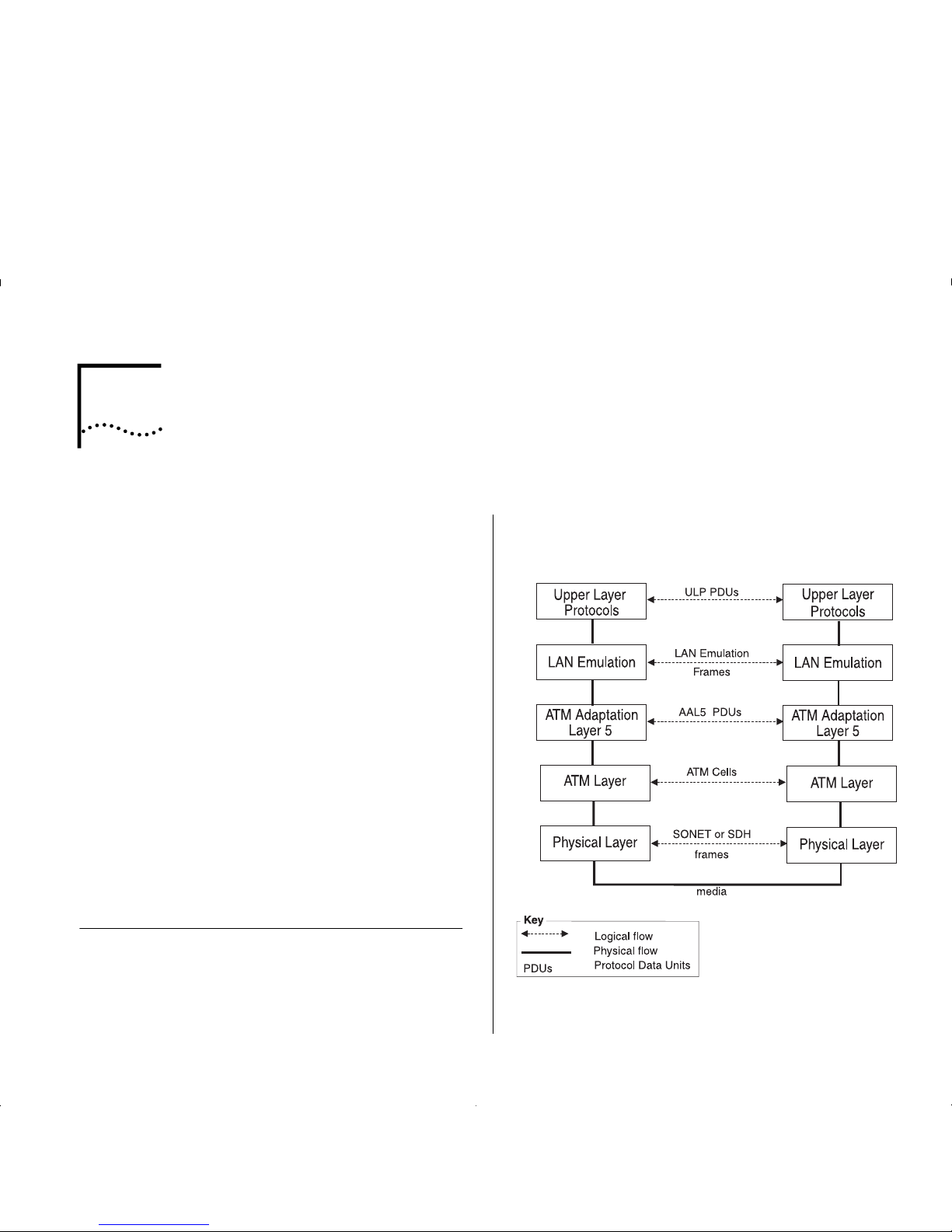
The Layered Network Architecture
Asynchronous Transfer Mode (ATM) is on ly part of a
layered net wo rk arch ite ct u re. Th is ar chit e c ture is
shown in Figure 2-1.
Each of the layers in discussed in turn; starting with
the Upper Layer and working down to the Physical
Layer.
Figure 2-1
Network Layer Architecture
Page 14

2-2 C
HAPTER
2: N
ETWORK LAYER CONCEPTS
Upper Layer Protocols
The
Upper Layer
is the layer in the network architecture
that rel a tes to user applications and service requ ests.
For example, an application could be fi l e transfer
softwar e, and t he ser vic e reque st c ould be a req uest t o
transfer a file from a user’s PC to a shared file server.
User data and control information is passed down the
network layers in the source device, and passed up
the layers at the destination device.
What is LAN Emulation (LANE)?
LAN Emulation (LANE)
allows users on Ethernet,
Token Ring, and other traditional LAN networks, to
communicate with each other over an ATM network.
LANE emulates the broadcast nature of traditional
LANs. Each LANE broadcast domain is known as an
Emulated LAN (ELAN)
.
Each ELAN can only carry one type of traffic. For
example, an ELAN could carry either Ethernet frames
or Token Ring frames, but not both.
There can be several ELANs on a single ATM network.
Some of these ELANs could be carrying Ethernet
traffic and others could be carrying Token Ring traffic.
T raffic from one ELAN is not seen on another ELAN, as
they are logically separate broadcast domains. If devices
from different ELANs need to communicate with each
other, t hey must do so using an ATM ro uter.
LAN emulation software is contained within ATM
devices which can be added to your existing network.
LANE allows you to add ATM to your network
without having to replace or upgrade the whole of
your underlying technology. LANE allows you to do
this because it is completely transparent to the ATM
network and to the traditional LAN network,
end-users, operating systems and applications.
LAN Emulation allows users on traditional LANs to
communicate over ATM by performing the following
tasks:
■
Emulates the broadcast nature of LANs.
■
Maps MAC addresses to ATM addresses.
■
Maps upper layer connection-less technologies to
the
connection-oriented
ATM network.
Although LAN Emulation emulates a range of
network technologies, all examples in this guide are
be based on an Ethernet network.
Page 15

What is LAN Emulation (LANE)? 2- 3
LAN Emulation Components
Each
Emulated LAN (ELAN)
is composed of a set of
LAN Emulation components. This section describ es
each of these components.
LAN Emulation Client (LEC)
Each ATM de v ic e has a number of LAN Emul at i on
clients. Each
LAN Emulation Client (LEC)
is responsibl e
for tak i ng Ethernet fr am e s and passing them through
the ATM network to the LEC se rving the destination
address. The dest ination LEC is r esponsible for re ceiving
the frame from the ATM network and passing it to the
local Ethernet network, where it can be delivered to the
destination address.
LAN Emulation Server (LES)
Each
LAN Emulation Server (LES)
controls a single
Emulated LAN (ELAN)
. The purpose of the LES is to
store address and control information for the ELAN it
is serving, and to pass this information onto the
clients and other components within the ELAN.
The LES, therefore, needs to know the address of
every client and component in the ELAN.
Broadcast and Unknown Server (BUS)
Each ELAN has a
Broadcast and Unknown S erver (BU S)
.
The BUS fo rward s frames that it receiv es fro m a n y
client to all of the clients in the ELAN. The BUS is used
to forward broadcast and multicast frames so that they
are
flooded
throu ghout the ELAN . The BUS also
floods
unicast frames if the location of the destination MAC
address is u nkn own.
LAN Emulation Configuration Ser ver (LECS)
The
LAN Emulation Configuration Server (LECS)
is an
optional component, and is not essential for the
normal running of an ELAN
.
The LECS stores the names of all th e ELA Ns that ha ve
been set up on the ATM network, and the address of
the
LAN Emulation Server (LES)
that serves each of
these ELANs.
If there is an LECS on the network, any client can
interrogate the LECS to find the address of the server
associated with the ELAN they wish to join. The
clients may also get ELAN configuration information
from the LECS.
If a LECS is not present on the A TM network, the server
addres s to be used by the clie nt must be specif ied using
the management software on that client’s ATM d evice.
Page 16

2-4 C
HAPTER
2: N
ETWORK LAYER CONCEPTS
LAN Emulation Components in Your Network
Each Emulated LAN consists of a single
LANE Service
,
and a number of LAN Emulation clients.
A LANE Service consists of:
■
A
LAN Emulation Server (LES)
■
A
Broadcast and Unknown Server (BUS)
■
Optional
LAN Emulation Configuration Server (LECS)
.
Figure 2-2 shows a logical view of a typical ELAN.
Figure2-2
LAN Emulation Components
The router shown in Figure 2-2 is not a LAN
Emulation component, but would be required should
a device on one Emulated LAN need to communicate
with a device on another Emulated LAN.
You may wish to have more than one LECS on your
network for security reasons. For example, you may
wish the Finance department to be controlled by one
LECS and the rest of your network to be controlled by
a different LECS.
LAN Emulation and IBM Devices
LAN Emulation components are implemented in ATM
dev ic e s . The L A N Emulatio n standards ( re f erence d i n
the Bibliography) do not specify how each vendor
implements each of these components.
Page 17

What is LAN Emulation (LANE)? 2- 5
Joining the ELAN
Before a LAN Emulation Client (LEC) can transmit any
Ethernet frames onto the ATM network it must first
join an ELAN . To join the ELAN:
1
The LEC must know the name of the ELAN it is to
join.
The ELAN name is specified through the management
software on the Switch.
2
The LEC must communicate with the LAN
Emulation Server (LES) that is serving that ELAN.
To communicate with the LES, the LEC must first
locate the LES. The LEC can find the ATM address of
the LES in one of the following ways:
■
If there is a LAN Emulation Configuration Server
(LECS) on the networ k, the LE C gets the ad dr ess of
the LES from the LECS.
The way in which the LECS determines which LES
the LEC needs to communicate with, depends on
the
policy
that the LECS is running. Refer to the
user guide that accompanies your LECS for more
details of the policies your LECS uses.
■
If the network does not have a LECS, the LEC gets
the LES address from the management software
on the ATM device.
3
The LEC must have a connection to the
Broadcast and Unknown Server (BUS).
When the LEC has joined the LES, the LES helps the
LEC locate the
Broadcast and Unknown Server
(BUS)
associated with that ELAN.
Locating the LECS
Before the LEC can ask the LECS for the address of
the LES, the LEC must first locate the LECS. There are
three ways i n w h ich th e LEC can locat e the LECS, and
the LEC tries these methods in the following order:
■
The LEC can ask the adjacent ATM Switch using
the
Interim Local Management Interface (ILMI)
.
■
The LEC can use a well known ATM addr es s that is
reserved for the LECS. The well known address is
pre-programmed into most LECS devices. The well
known address is:
47007900000000000000000000:00A 03E000001:00
■
The LEC can use a reserved
Permanent Virtual
Circuit (PVC)
which the ATM Switch has already
routed to the LECS. The reserved PVC is
VPI 0, VCI 17.
Page 18

2-6 C
HAPTER
2: N
ETWORK LAYER CONCEPTS
Mapping Ethernet and ATM Addresses
Each device connected to an Ethernet port has one or
more MAC addresses.
Each ATM device has a number of LAN Emulation
clients, and each
LAN Emulation Client (LEC)
has an
A TM address . A n exa mpl e of t hi s i s s how n in F i gur e2-3.
Figure2-3
LAN Emulation Clients and Ethernet Hosts
These clients represent (act as a proxy) for devices
connected to the Ethernet ports.
Whenever an Ethernet device wants to communicate
with another device over the ATM network, the LEC
must first discover the ATM address of the LEC that is
acting as a proxy for the destination MAC address.
The LEC must do this for each unicast Ethernet fram e
sent. The process is known as
Address Resolution.
Address Resolution
The process by which a LEC associates a LAN
destination address with the ATM address of another
LEC (or the BUS) is known as
Address Resolution
.
Each LEC keeps a LAN Emulation
ARP Table
(which
should not to be confused with the IP ARP Table). The
ARP T able lists the remote destination MAC addresses
and the ATM address of the LEC though which each
destination MAC address can be reached.
Prior to sending a frame with a known destination,
the LEC checks th e ARP Table to s ee if the dest inati on
MAC address of the frame is listed in the ARP Table.
The action the LEC then takes depends on whether
the MAC address is listed in the ARP Table:
■
If the destination MAC address is listed in the
ARP Table:
■
and there is an A TM connection to that LEC, the
frame is sent directly to that LEC.
■
and an ATM connection has not already been
set up, the LEC sets up an ATM connection.
■
If the destination MAC address is not listed in
the ARP Table
, the LEC sends the frame to the
BUS. The BUS then sends the frame to all LECs on
the Emulated LAN.
Sending a frame to every LEC is an inefficient use
of resources, so the LEC also tries to locate the
MAC address for future use.
To discover the correct address, the LEC uses a
process called
LAN Emulation Address Resolution
Protocol (LE_ARP)
.
Page 19

What is LAN Emulation (LANE)? 2- 7
LAN Emulation Address Resolution Protocol
(LE_ARP)
An LE_ARP request is sent to the LES to locate the
destination MAC address. The LES in turn sends the
LE_ARP request to all of the LECs in the E mulated LAN.
LECs represent (act as a proxy) for MAC address
devices connected to the Ethernet ports. When a LEC
receives an LE_ARP request it checks whether the
MAC address is on its Switch. It does this by checking
the entries in the Switch database.
If the MAC address belongs to one of the devices
connected to an Ethernet port, the LEC sends an
LE_ARP response to the LEC that sent the original
LE_ARP request.
The LEC that sent the LE_ARP request adds this
information to its ARP Table. The LEC then sets up a
direct connection through the ATM network to the
appropriate LEC, so that subsequent frames are
forwarded more efficiently.
What Happens to Unicast Frames?
The path a unicast frame takes through the ATM
network depends on whether the location of the
destination address is known to the sending LEC.
■
If the location of the destination address is
known
, the LEC sets up a direct connection to the
LEC serving the destination address.
■
If the location of the destination address is
unknown
, a unicast frame is sent to the
Broadcast
and Unknown Server (BUS)
; where it is treated in
the same way as a broadcast or multicast frame.
In addition the sending LEC attempts to locate the
LEC serving the destination address. It does this
using the LE_ARP process, described in “LAN
Emulation Address Resolution Protocol (LE_ARP)”.
What Happens to Broadcast and Multicast Frames?
Each
Emulated LAN (ELAN)
acts as a broadcast
domain. When a broadcast or multicast frame is
passed to the LEC for transmission, the frame is sent
to the
Broadcast and Unknown Server (BUS)
.
When the LEC receives a broadc as t, mul tic as t, or
unicast frame it checks to see if it originally sent the
frame, and then does the following:
■
If the LEC sent the frame, it discards the frame.
■
If the LEC did not send the frame, the LEC passes
the frame to the Ethernet device so that it can be
forwarded to the appropriate port(s).
Unlike broadcast and multicast frames, the number of
unicast frames that can be sent to the BUS every
second is limited so as not to overload the BUS and
LECs with too much traffic.
Page 20

2-8 C
HAPTER
2: N
ETWORK LAYER CONCEPTS
ATM Adaptation Layer (AAL)
Ethernet frames can be between 64 and 1514 bytes
in length. ATM transmits data in fixed length
cells
.
Each cell contains 48 bytes of user data. The
ATM
Adaptation Layer (AAL)
converts data between the
Ethernet and A TM formats.
The AAL has a
Segmentation and Reassemb ly (SAR)
sub-layer that does the conversion.
In the sending device the LEC passes the Ethernet
frames to the SAR. The SAR converts the user data
into fixed length cells, and passes these cells to the
ATM Layer for transmission across the ATM network.
In the receiving device, the SAR converts the ATM
cells back into the appropriate user data again, and
passes this data to the LEC.
As ATM can carry different traffic types (for example,
voice, video, and other data), several Adaptation
Layer protocols have been defined. These protocols
operate simultaneously within the Adaptation Layer,
and allow the ATM Layer to support different
applications and traffic types.
The IBM 8271 Nways Ethernet LAN Switch ATM
OC-3c Module uses the AAL5 ATM Adaptation Layer
protocol, which is a data-oriented protocol. The ATM
Module will only work with other AAL5 devices.
Asynchronous Transfer Mode (ATM) Layer
Asynchronous Transfer Mode (ATM)
is a connectionoriented transmission protocol that has the following
features:
■
ATM us es the
Signalling Protocol (Q.2931)
to
dynamically create, maint ain and clear ATM
connections between end-systems.
■
ATM uses fixed length packets known as
cells
, and
each cell identifies the connection to be used.
■
ATM is transparen t to the m ul t ip l e se rv i ces it
supports and c a n c arry cells f rom diffe rent
applications over the same physical connection.
■
ATM has well-defined user and network interfaces.
ATM is Cell-based
ATM uses fixed length packets called
cells
. The first
five bytes of the cell is the
cell header
. The cell he ader
contains the information necessary to deliver the cell
to the correct destination.
Fixed-length cells offer smaller and more predictable
switchin g d e la ys, be ca u se ce ll switching is le ss
complex than variable-length packet switching.
Having all the data in the same cell format also
dramatically increases the speed of transmission, by
eliminating the need for protocol recognition and
decoding. A good analogy is containerized shipping,
where uniform shape and weight containers with
standardized labelling, ease and speed up processing.
Page 21

Asynchronous Transfer Mode (ATM) Layer 2-9
ATM is Service Transparent
ATM allows for the high speed transfer of a wide range
of user traffic, inc l uding voice, v ideo and other da ta.
The cell format means that more than one service
(traffic type) can be
multip lexed
over the same
physical line, see Figure 2-4.
Figure2-4
Service Processing
Cells ar e
de-multiplexed
at the other end of the
connection and forwarded to the correct service
destination.
Multi-service processing promotes scalability by
significantly reducing the number of changes needed
to add new service traffic types to your network.
ATM is Connection-oriented
ATM is a
connection-oriented
transport service that
requires a communication channel to be set up
between the ATM source and destination end-systems
before ATM cells can pass between them.
Before a direct data connection can be set up
between two end-systems, a number of control
connections are set up. These control connections are
beyond the scope of this guide. If you require further
information about control connections, refer to the
ATM Forum’s “LAN Emulation Over ATM” document.
Figure 2-5 shows the logical structure of a
communication channel.
Figure 2-5
Communication Channels
Several communication channels can operate over the
same physical link. Each
Virtual Path Connection (VPC)
contains several communication channels known as
Virtual Channel Connections (VCCs)
.
The ATM Module only manages Virtual Channel
Connections (VCC).
Page 22

2-10 C
HAPTER
2: N
ETWORK LAYER CONCEPTS
A VCC is defined as spanning end-to-end, whereas a
Virtual Channel (VC)
is the name given to a section of
the VCC, refer to Figure 2-6.
Figure2-6
Connection Terminology
Many virtual channels can exist on the same physical
link. Each virtual channel is identi fie d by a pair of
numbers:
■
The
Virtual Path Identifier (VPI)
and
■
The
Virtual Channel Identifier (VCI)
.
Any end-system that wishes to communicate with
another end-system must first use the
Signalling
protocol to set up the VCC.
The
Signalling
protocol negotiates with each ATM
device between the end-systems to set up a series of
virtual channels. Each of these virtual channels is
identified u sing the VPI and VCI values.
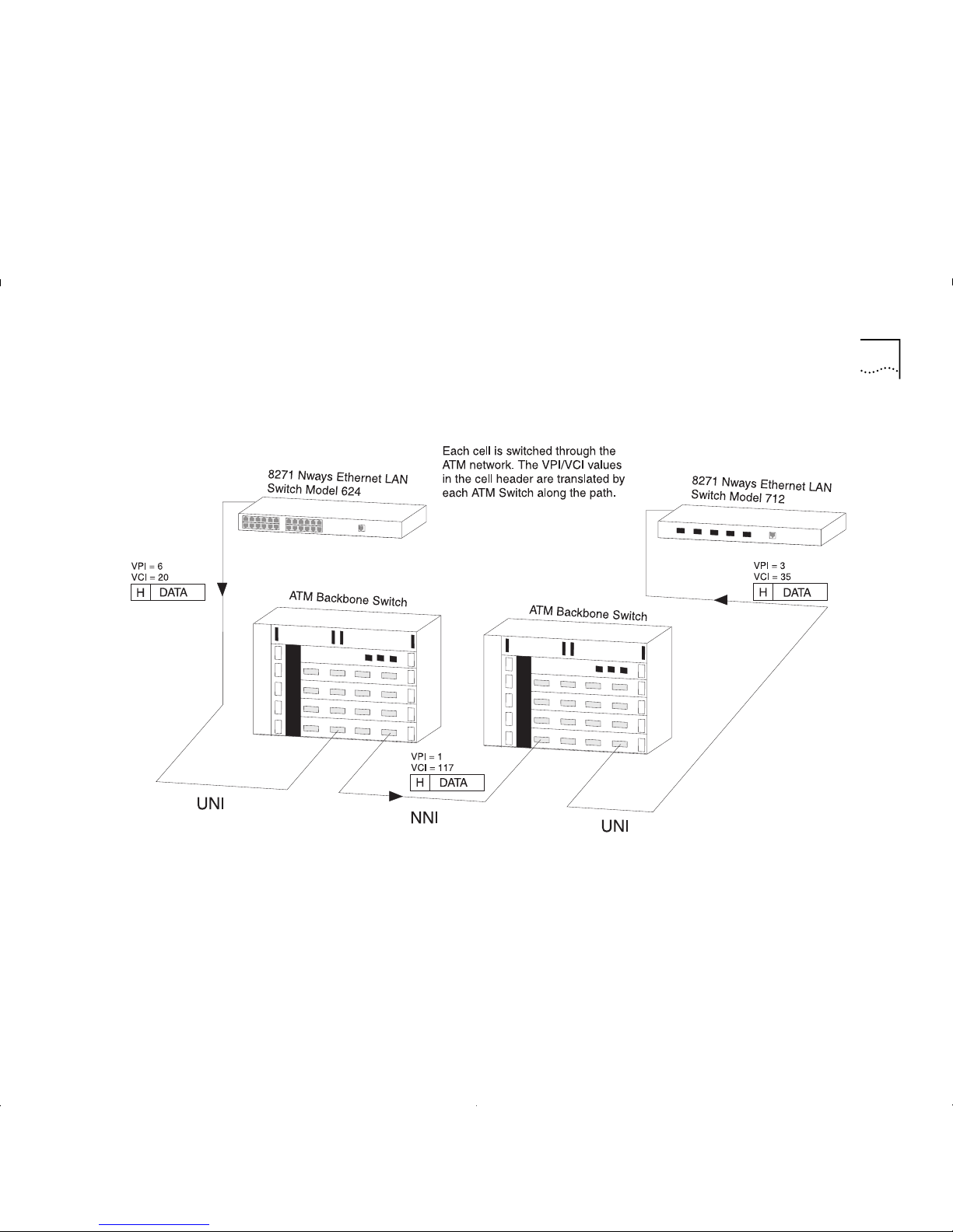
Figure 2-7 on page 2-11 shows how ATM cells are
switched through the A TM network using the VPI/VCI
values.
Instead of containing the ATM address of the final
destination device, each cell header contains the
VPI/VCI values associated with the virtual channel it is
going to take to get to the next ATM Switch in the
connection.
Each ATM switch kno w s th at when it r eceives a cel l
with a particular VPI/VCI value on one port that it must
transmit the cell on another port with another VPI/VCI.
Cells are switched through the network based on
these VPI/ VC I va lues, and swit c hin g is p e rf o rme d
independently for every cell. Each cell can be thought
of as taking a virtual channel connection.
The VPI/VCI values are only meaningful in the c onte xt
of that user-to-switch, or switch-to-switch, interface.
Identica l VP I/ VCI values ca n e xist on differ e nt
interfaces within the network.
Connections t ha t ar e e stabl ishe d d ynamica lly usi ng the
Signalling protocol are known as
Switched Virtual
Circuits (SVCs). Switche d V irtual C i rc uits
are described
in “Switched Vir tual Circu i ts (SVCs)” on pa ge 2-12.
ATM connections can also be established via
management, and these type of connections are
known as
Permanent Virtual Circuits (PVCs)
.
Permanent Virtual Circuits
are described in
“Permanent Virtual Circuits (PVCs)” on page 2-12.
Page 23
Asynchronous Transfer Mode (ATM) Layer 2-11
Figure2-7
Switching Cells using VPI and VCI values.
Page 24

2-12 C
HAPTER
2: N
ETWORK LAYER CONCEPTS
Switched Virtual Circuits (SVCs)
SVCs use the signalling protocol to dynamically define
connections as they are needed and to release them
when they are no longer needed.
SVCs use signalling for:
■
Connections initiated by the user/application.
■
Connections established and dropped dynamically.
■
Varied connection time.
■
Connections not automatically re-established after
network failure.
Permanent Virtual Circuits (PVCs)
The most basic connection setup requires the
definition of each connection via management. These
type of connections generally remain established for
long periods of time.
PVC attributes include:
■
Connections initiated by network management.
■
Long-term connection duration.
■
Automatically re-established after network failure.
■
Supported by MIB or other management entity.
The ATM Module does not support PVCs.
ATM Interfaces
ATM technology is implemented in A TM edge-devices
and ATM Switches.
ATM provides a
User-to-Network I n terface
(UNI). The
User-to-Netw o rk Interfac e (UNI) is us ed to con nect an
ATM edge devic e to an ATM switch that is managed
as part of the same network.
ATM al so provides a
Network-to-Network Interface (NNI)
that is typically used to interconnect two ATM switches
managed as part of the same network.
The ATM Interfaces are shown in Figure 2-8.
Figure 2-8
ATM Interfaces
The User-to-Network Interface (UNI) is managed by the
Interim Loca l Management Interface (ILMI)
protocol.
Page 25
Asynchronous Transfer Mode (ATM) Layer 2-13
Interim Local Management Interface (ILMI)
The ATM Forum produced the
Interim Local
Management Interface (ILMI)
to increase monitoring
and diagnostic facilities, and to provide ATM address
registration at the
User-to-Network Interface (UNI)
.
ILMI uses a
Management Information Base (MIB)
and
the
SNMP
protocol.
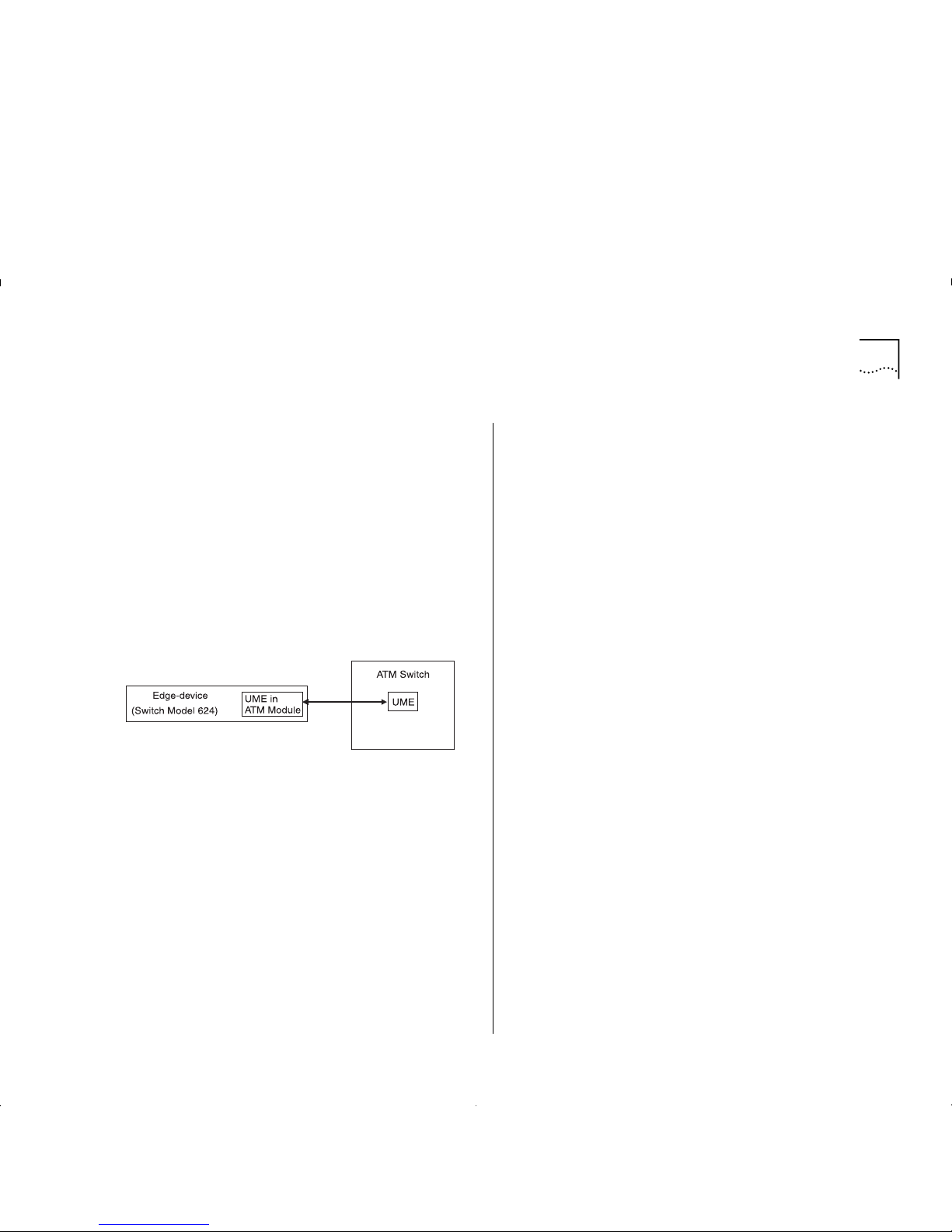
Each device that provides ILMI support contains a
UNI Management Entity (UME)
, which uses SNMP to
access management information stored in the ILMI
MIB of the adjacent switch, see Figure 2-9.
Figure2-9
UNI Management Enti ti es
ATM Address Registrati on
In order to establish an ATM connection, both the
user and the network must know the ATM addresses
used at that
User -to-Ne twork Int erfac e (UNI)
. An
example of an ATM address is shown below.
47007900000000000000000000:00A03E000001:00
An ATM address consists of three sections of
information and is 20 bytes in length:
network:host:identifier
Where
network
is a network prefix assigned to the
device by the ATM Switch, and is 13 bytes long.
Where
host
is the edge-device identifier, and is 6
bytes long.
Where
identifier
identifies the client within the
edge-device, and is 1 byte long.
ILMI provides a mechanism for the edge-device (in
this case the ATM Module) to inform the ATM Sw i tch
of the addresses it represents.
When the ATM Module initializes, the ATM Switch
sends a network prefix to th e ATM Module. The ATM
Module then tries to register itself with the ATM
Switch by attaching the prefix to the front of its MAC
address, and an identifier to the end of the address. It
then sends this back to the A TM switch. If a cceptable,
the ATM Switch registers the address as the ATM
Module’s ATM address.
Page 26

2-14 C
HAPTER
2: N
ETWORK LAYER CONCEPTS
The ATM Layer and Cell Structure
This section describes the cell structure, and how the
ATM Layer uses the information stored in the cell
header to perform each of its task s.
The ATM Layer’ s primary responsibility is to manage
the sending and receiving of cells between the user
and the network.
The A TM Layer acc ept s the user data and control
information from the ATM Adaptation Layer , adds the
cell header, and passes the resulting 53 byte cell to
the physical layer.
In addition, it also receives cells from the physical
layer, strips off the cell header and passes the
remaining 48 bytes to the higher layer protocols.
The ATM cell has 48 bytes of payload (information to
be carried) and five bytes of header information,
making the cell 53 bytes in length.
The cell header contains the information used by the
network to forward each cell to its destination. The
AT M cell structure is shown in Figure 2-10.
Figure2-10
ATM Cell Structure
The ATM cell header consists of the following fields:
Generi c Flow Control (GFC)
— Provides local
functions, such as flow control over the
User- to Network I nterface (UNI)
. The valu e enco ded i n
the GFC is not carried end-to-end and can be
overwritten by the ATM Switch.
Virtual Path Identifier (VPI)
and
Virtual Channel
Identifier (VCI)
— The VPI/VCI values allow the
network to associate a cell with a given connection,
so that the cell can be switched to its destination.
Payload Type Identifier (PTI)
— The PTI is used to
indicate whether the cell contains user information,
or management information. The management
information is used for resource and network
congestion management.
Cell Loss Priority (CLP)
— The purpose of the
Cell
Loss Priority (CLP)
bit in the A TM cell is to i ndicate that
cells with this bit set should be discarded before cells
which do not have the CLP bit set. Cells can be
discarded based on CLP condition and according to
the network load. When the network overloads, a
discard mechanism, based on the value of the CLP bit
in the cell header, may come into operation.
Header Error Check (HEC)
— The HEC field is used
for detecting bit errors in the cell header. It is also
used for cell delineation, defining where the cell
begins in a SONET frame.
Page 27

Physical Layer 2-15
Physical Layer
The physical layer is responsible for transmitting and
receiving ATM cells over a physical medium. It is also
responsible for checking the integrity of the bits being
transferred over a physical media, and for making
sure that they are error-free.
The ATM Module is compliant with both
SONET STS-3c
and
SDH STM-1
physical layer standard s.
These standar d s ar e similar, and most devices allow
you to use either framing standar d on each link in the
AT M network.The same framing standard must be
used at each end of the link.
Many users prefer to use the same framing st anda rd
throughout the ir ne twork (f or example SONET STS-3c ).
The physical layer is sub-divided into:
■
Path
— SONET and SDH are capable of carrying
traffic for a number of uppers layers, and ATM is
only one of those layers. Each upper layer uses its
own
Path
through the SONET/SDH layer.
■
Line
— A
line
is the whole path between one ATM
device and the adjacent ATM switch or ATM
end-station.
■
Section
— When ATM is used for telephone
networks, a
line
may cover a large distance,
requiring optical repeaters to boost the signal
along its way . The part of a
line
between an optical
repeater and the adjacent repeater or switch is
known as a
section
.
SONET STS-3c
Synchronous Optical N et w ork (SONET) is the phy sical
layer most often associated with ATM. SONET provides,
throug h a f raming struc ture, the mechanism for the
transport of AT M c ells. Data c a n be transferred at
155.52Mbps.
SDH STM-1
SDH STM-1 is a physical layer similar to the SONET layer,
but with some differences in frame fields. SDH STM-1 is
the physical layer commonly used in Europe.
The physical layer and ATM layers in the network
provide simple performance monitoring functions
between ATM devices; providing basic information
about the health of the link. These functions are
known as “Operation and Maintenance (OAM)”
functions.
Page 28

2-16 C
HAPTER
2: N
ETWORK LAYER CONCEPTS
Page 29

3
V
IRTUAL
LAN C
ONCEPTS
This chapter provides a brief overv i ew of
Virt ual LAN (VLAN) concepts, and describes how to
extend VLANs into the ATM network.
This user guide does not describe how to create or
configure VLANs. VLAN configuration is described in
the user guide that accompanies your Switch.
What is a Virtual LAN (VLAN)?
A V irtual LAN (VLAN) is a fle xibl e, loc ati on and t opolog y
independent group of end-stati ons communicating as
if they are on a common physical LAN.
You can create VLANs that closely correspond to how
your network and business functions. For example,
marketing personnel in different physical locations
could be part of one VLAN and finance personnel
could be in another VLAN.
VLANs provide the following benefits:
■
VLANs make mo ves an d cha nge s sim ple .
■
As each VLAN is a common broadcast domain, you
can erect firewalls against broadcast storms.
■
VLANs improve security.
For a full description of VLAN functionality, refer to
the user guide that accompanies your Switch.
Creating Inter-switch VLANs
You can create inter-switch VLANs using Virt ual LAN
Trunks (VLTs ) on Fast Etherne t connec tions, as shown
in Figure 3-1.
Figure 3-1
Inter-sw itch VLANs
Page 30

3-2 C
HAPTER
3: V
IRTUAL
LAN C
ONCEPTS
Extending VLANs into the ATM Network
You can use LAN Emulation to define and extend
VLANs seamlessly through the ATM network, as
shown in the example in Figure 3-3.
Traffic from one
Emulated LAN (ELAN)
is not seen on
another ELAN as they are logically separate domains.
For this reason, when you plan your network, you
should consider what ELANs you require, and how
the VLANs will map to these ELANs.
The A T M Module has a LE C for each of th e Switch ’s 16
VLANS, and each VL A N/ L EC c an be mapped onto an
Emulated LAN (ELAN)
. In this way , E thernet traffic is
mapped to an ELAN by a VLAN-to-LEC association. The
mapping of VLANs to ELANs is shown in Figure 3-2.
When an Ethernet device attached to a Switch
generates traffic, the Switch forwards the frames to
the appropriate port.
A unicast frame is only forwarded to a port if the
address of the destination device is known to be on
that port and the destination port is in the same
VLAN as the source port. If a unicast frame is
forwarded to the ATM port, the ATM port uses the
destination MAC addr es s to identify the ATM
connection to use.
A broadcast or multicast frame is forwarded to all
ports in the same VLAN as the source port. If a frame
is received by the ATM port, the ATM port forwards i t
to the BUS for the associated VLAN.
Figure 3-2
VLAN to ELAN M apping
Page 31

Extending VLANs into the ATM Network 3-3
Figure3-3
Extending VLANs into the ATM Network.
Page 32

3-4 C
HAPTER
3: V
IRTUAL
LAN C
ONCEPTS
Page 33

4
P
UTTING
Y
OUR
ATM N
ETWORK TOGETHER
This chapter takes you through the process of
planning your network. Topics include:
■
Planning and tracking your network configuration.
■
AT M Configuration Rules.
■
Extending Virtual LANs (VLANs) into the ATM
network.
■
AT M connection types.
Planning Your Network
Before installing your ATM devices you shou ld spe nd
some time planning your network structure. This
section lists some of the points you should consider.
■
Are routes defin ed w it hi n y ou r ATM network
so that your ATM devices can connect to your
LAN Emulation services?
Examine your existing network topology and
decide if further configuration is required. In
particular , you should consider the location of your
LAN Emulation services .
■
Does your existing ATM network have
sufficient resources?
Consider the capacity of:
■
Your ATM Switc hes, and the num be r of
additional c onnections yo ur ATM device requires.
■
Your LAN Emulation services, and the number
of additional LAN Emulation Clients (LECs) your
ATM edge-device will a ttempt to join.
■
Can your ATM devices communicate with each
other?
■
Ensure that all of your ATM equipment is using
the same line f ram in g and signallin g protocols.
■
Ensure that al l inter-switch routes ar e c onfig ur ed
correctly.
■
How do you intend to manage the ATM
network?
Can the network manager communicate with the
ATM devices you wish to manage? Check the
routing tables.
Page 34

4-2 C
HAPTER
4: P
UTTING YOUR
AT M N
ETWORK TOGETHER
■
Does your network meet s afety specifications?
You should always follow safety requirements and
ensure that your device environment meets all
technical specifications.
For the ATM Module these requirements are specified
in Appendix A. For other devices, refer to the user
guides that accompany those devices.
■
Does your networ k conform to the ATM
configura t ion rules?
Make sure that your network meets the con figurati on
rules described in “ATM Configuration Rules”.
ATM Conf igurati on Rule s
There are several things that you should consider
before configuring your network:
■
Your cables and equipment must meet all of
the tech nical specifications.
The ATM cable you connect to the ATM Module,
must conform to the Multi-Mode Fiber (MMF-PMD)
standard defined by ANSI x.3-166-1992.
3Com supports 62.5/125mm multi-mode fiber
(MMF-PMD) cable. The maximum inter-s tation
distance (including device- to-network connectors)
should not exceed 2km (1.25 miles).
■
Allow for attenuation (weakening of sign al)
when calculat i ng cable lengths.
■
Ensure that you have sufficient bandwidth.
Refer to Appendix C, “ATM Module Technical
Specifica t ions” for more deta ils.
You cannot connect an IBM 8271 Nways Ethernet
LAN Switch ATM OC-3c Module to another IBM 8271
Nways Ethernet LAN Switch ATM OC-3c Module; this
is due to the signalling requirements used by ATM
and LANE. There must be a standards-based ATM
Switch between the two modules for them to operate
correct ly.
Extending VLANs Through the ATM Network
When setting up VLANs and extending them into the
ATM network you should consider the following:
■
What logical network domains, VLANs, do
you wish to set up?
Traffic from one
Emulated LAN (ELAN)
will not be
seen on another ELAN (unless a r outer i s used), as
they are logically separate domains. For this r eas on
you should consider:
■
What ELANs you require.
■
How the VLANs will map to the ELANs.
■
If you need to route between any of your ELANs.
■
Will you have sufficient ELAN resources?
When calculating the resources you require, you
should consider the number of:
■
ELANs that your LAN Emulation services can
support.
■
VLANs/ELANs th at ea ch edg e-dev ice ca n supp ort.
Page 35
ATM Connections Within Your Network 4-3
■
Virtual circuits required.
■
MAC addresses that can be held in the device
LAN Emulation ARP Table.
When a
LAN Emulation Client (LEC)
joins an ELAN,
up to five control connections may be required
before any data is transferr ed over a s eparate data
connection (VCC). Each time a LEC connects to
another LEC a further connection is required. You
should keep this in mind when calculating the
number of connections you require.
The ATM Module provides the following resources:
■
Up to 16 LECs to extend VLANs into the ATM
network over ELANs.
■
512 Virtual Circuits to/from the ATM network.
■
1024 remote MAC Addresses.
The ATM Module supports only 16 LECs, but this does
not limit your network to 16 ELANs.
■
Are the LAN Emulation services configured
correctly?
Is the LAN Emulation service that the
LAN Emulation
Client (LEC)
is going to joi n configured corre c tly ?
For example, if your network uses a
LAN Emulation
Client Server (LECS)
, does the LECS know about
the LES, and is the LES active? Have you supplied a
valid ELAN name?
Configuring t he LECS and LES is outside of the scope
of this user guide. C onsult the user guide that
accompanies the device implementing the LECS or LES.
Alternatively, if your LEC will not be using a LECS
and is being configured manually, ensure that:
■
The LES address that the LEC is using has been
correctly entered via the local management
screens.
■
The LES is active.
For the ATM Module, you can enter these settings
using the Port Configuration screen described in
“Displaying an ATM Connection”, on page 8-10.
ATM Connections Within Your Network
ATM connections in your ATM network can be
established dynamically by the
Signalling
protocol
(
Switched Virtual Circui t
), or through management
(
Permanent Virtual Circuit
).
The ATM Module doe s no t sup port PVC
connecti ons
. All A TM Module connections are SVCs.
This network concepts section includes PVC
configuration concepts for completeness.
■
Switched Virt ual Circuits (S VC)
— SVCs are set
up dynamically by the signalling protocol. SVCs
require very little configuration, and only use the
resources you need. For these reasons, SVCs are
commonly used in the LAN environment.
■
Permanent V i rtual Circuits (PVC)
— You may
need to use a PVC within your network when a
remote edge-device does not support
Switched
Virtual Circuits
. For example, remote edge-devices
in
Wide Area Networks (WANs)
often use PVCs.
Page 36
4-4 C
HAPTER
4: P
UTTING YOUR
AT M N
ETWORK TOGETHER
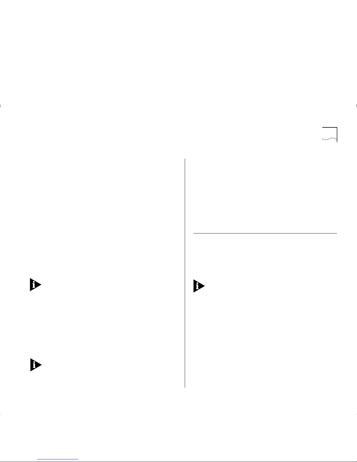
Figure 4-1 shows an example of a network
configuration where a remote edge-device does
not support LAN Emulation based on SVCs (it only
supports PVC LAN Emulation).
Figure4-1
SVC Signalling Not Supported in Remote Edge-device
Page 37
5
N
ETWORK
C
ONFIGURATION EXAMPLES
This chapter provides examples of possible network
configurations using the ATM Module. If you are
unfamiliar with ATM, you should read this chapter in
conjunction with Chapter 4, “Putting Your ATM
Network Together”.
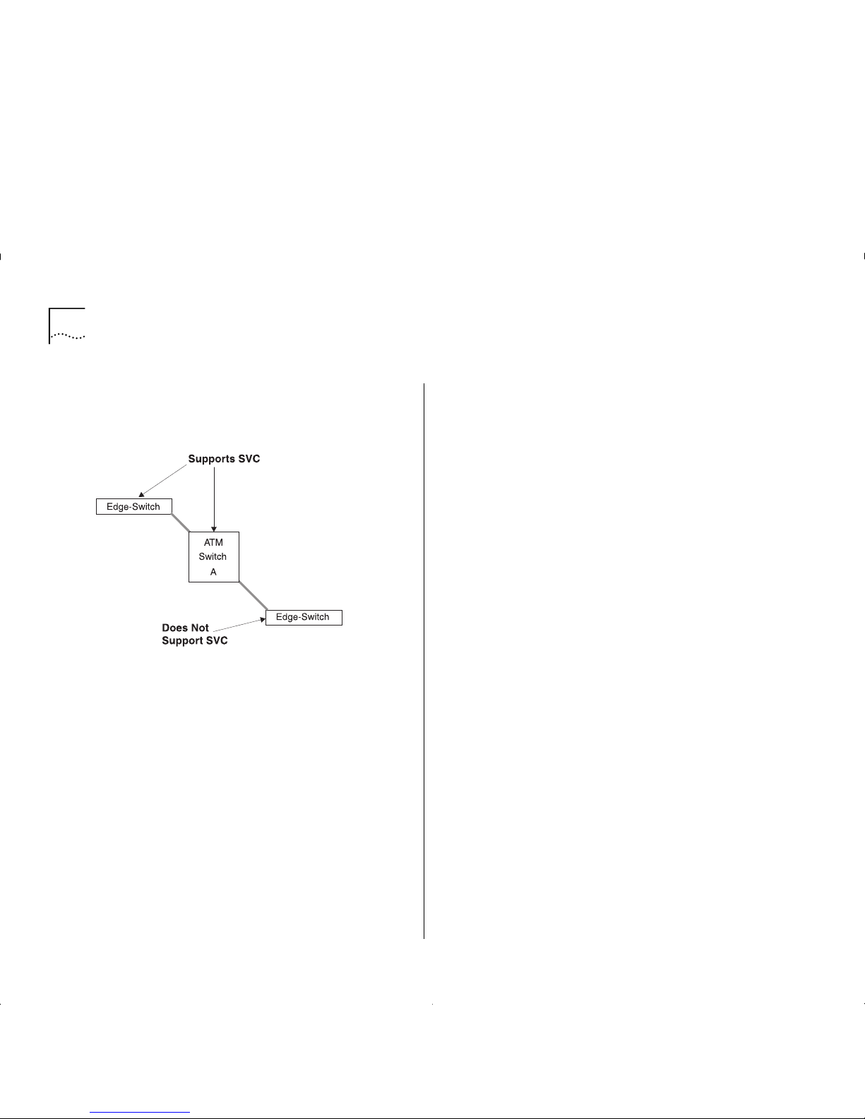
ATM Backbone in the Building
This section gives an example of an ATM backbone
within a single building, as shown in Figure 5-1.
In this case, the Ethernet Switch on each floor is
provided with a high speed (155Mbps) full duplex link
to the backbone. Using ATM as a backbone
technology removes bottlenecks by providing scalable
bandwidth, low-latency, high-speed data switching.
Ethernet VLANs can be extended into the ATM
network using Emulated LANs (ELANs). Et h erne t
packets are then switched between Ethernet to ATM
transparently.
As well as providing a fast switched backbone
between Ethernet LANs, ATM equipped file servers
and services may be directly attached to the ATM
network; giving improved performance to the
Ethernet desktop.
Further advantages are gained in multi-media
applications, due to ATM’s built-in quality of service.
Figure 5-1
ATM Backbone in the Building
Page 38

5-2 C
HAPTER
5: N
ETWORK CONFIGURATION EXAMPLES
Campus Configuratio n
The section gives an exampl e of A TM within a campus
environment. The diagram shown in Figure 5 -2 on
page 5-3 demonstrates a balance between cost and
performance requirements.
Building A
shows how you can concentrate IBM
8721 Nways Ethernet LAN Switch Model 612 and
624 devices using an IBM 8271 Nways Ethern et LAN
Switch Mod el 71 2 . All t raffi c in te r na l t o Building A is
switched over Fast Ethernet. In addition, an ATM link
to the campus backbone provides high speed access
to remote services.
Building B
shows how you can configure a building
in a cost efficient manner, while retaining connectivity
to the campus ATM network.
Only one A TM Module is required to connect the IBM
8271 Nways Ethernet LAN Switch Model 624 and
Switch Model 524 devices to the ATM network. This
provides connectivity for 48 Ethernet ports t o t he ATM
backbone.
Building C
shows you a building similar to Building A,
but with additional campus-wide, high performance
access to directly connected ATM servers.
Page 39

Campus Configuration 5- 3
Figure5-2
Campus and Cost Sensitive Network
Page 40
5-4 C
HAPTER
5: N
ETWORK CONFIGURATION EXAMPLES
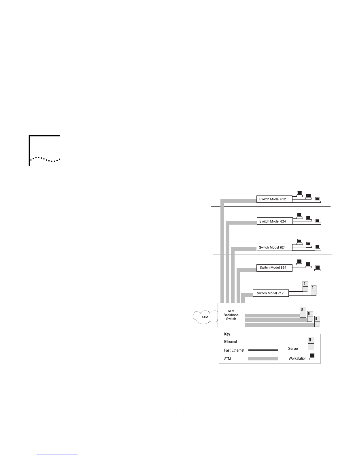
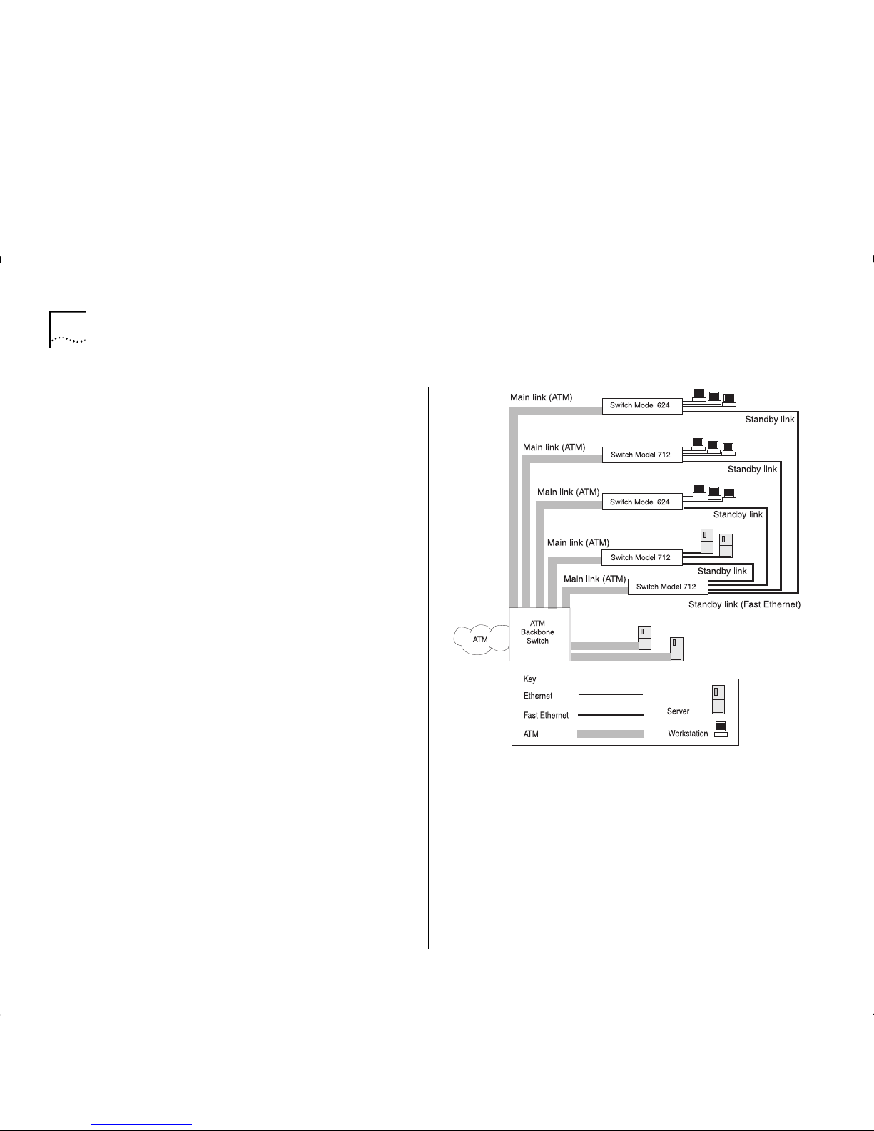
Making a Building Resilient to Network Failure
You can build resilience into your building backbone
as shown in Figure 5-3. The provision of resilient links
protects your network against cable and network
failure by using a main and a standby link. Should the
main link fail, a standby link automatically takes over
the function of the main link.
In this example, the ATM Module fiber link provides
the main link in t he resil ie nt link p ai r, and the Fast
Ethernet fiber or copper link acts as the standby link.
This configuration ensures that all devices have access
to a high-speed backbone connection at all times.
Figure 5-3
Resilient Link Configuration
Page 41

6
I
NSTALLING AND SETTING
UP
THE
M
ODULE
Following Safety Information
ATTENTION: Only hold the ATM Module by the
edges to avoid damage from static. Do not touch the
top or bottom of the circuit board.
DANGER: Before installing or removing
anycomponents of a device, or carrying out
anymaintenance work, you must read the safety
informationprovided in Appendix A, “Safety
Information” of this guide.
Danger: Avant d’installer ou de retirer les
composantsd’une unité, ou de procéder à une
opération de maintenance,vous devez prendre
connaissance des consignes de sécurité figurant à
l'annexe A, “Consignes de sécurité” du présent
manuel.
Achtung: Vor dem Installieren oder Entfernen von
Komponenten einer Einheit, bzw. vor dem Ausführen
von Wartungsarbeiten unbedingt die
Sicherheitshinweise in A nh a ng A ,
“Sicherheitshinweise”, dieses Handbuchs lesen.
Gevaar! Alvorens een component van een apparaat
te installeren of te verwijderen, of alvorens een
onderhoudstaak uit te voeren, moet u de
veiligheid srichtlijne n le ze n in Ap p e nd ix A, “Sa fe ty
Information”, van deze handleiding.
Perigo: Antes de instalar ou remover qualquer
componente de um dispositivo, ou executar qualquer
trabalho de manutenção, você deve ler as
informações sobre segurança fornecidas no Apêndice
A, “Informaçõíes de Segurança” deste guia.
Fare: Læs sikkerhedsforskrifterne i tillæg A,
“SafetyInformation”, i denne vejledning, inden du
installerer ellerafmonterer en enheds komponenter
eller udfører vedligeholdelsesopgaver.
Gevaar: Voordat u onderhoudswerk uitvoertof
componenten van een apparaat installeert of
verwijdert,dient u eerst de veiligheidsvoorschriften te
lezen in Appendix A, “Safety Information” van deze
handleiding.
Pericolo: Prima di installare o di rimuovere qualunque
componente di un dispositivo e prima di eseguire
qualunque intervento di manutenzione, bisogna
leggere le inf or m az ion i relative alla sicu rez za fornite
nell'Appendice A di questaguida.
Fare: Før du installerer eller fjerner komponenter i en
enhet eller utfører vedlikeholdsarbeid, må du lese
sikkerhetsinformasjone n i Appendix A, “Safety
Information” i denne boken.
Perigo: Antes de instalar ou remover qualquer
componente de um dispositivo ou de executar
Page 42

6-2 C
HAPTER
6: I
NSTALLING AND SETTING UP THE MODULE
qualquer trabalho de manutenção, deve ler o
conteúdo do Apêndice A, “Informações sobre
Segurança”, deste manual.
Peligro:
Antes de instalar o extraer
cualquiercomponente de un dispositivo, o realizar
cualquier trabajo de mantenimiento, debe leer la
información de seguridad incluída en el Apéndice,
“Información de Seguridad” de esta guía.
FARA:
Lãs avsnittet “Safety Information” i Appendix
A i det här dokumentet innan du utför
underhållsarbete eller installerar/demonterar
komponenter.
VAARA
: Ennen kuin asennat laitteeseen osia tai
irrotat niitä siitä tai teet huoltotoimia, lue tämän
julkaisun liitteessä A, “Safety Information”, olevat
turvaohjeet.
ebezpečí:
řed instalací nebo odstraněním libovolné komponenty ze zařízen
í
ebo před prováděním údržby si musíte přečíst bezpečnostní
nformace z této publikace (Appendix A, "Safety Information").
Опасно:
Перед установкой или удалением какого-либо элемента
устройства и проведением технического обслуживания
необходимо ознакомиться с информацией по технике
безопасности, приведенной в Приложении А,
"Информация по технике безопасности".
Nebezpečenstvo:
Pred inštaláciou alebo odobratí ktorej koWvek jednotky, alebo inej
práce spojene s daným zariadením, musíte si prečítaÝ bezpečnostné
predpisy v Appendixe A, "Bezpečnostné predpisy" v tejto knihe.
Nevarnost !
Preden instalirate ali odstranite neko komponentno iz naprave ali kadar izvajate vzdrevalna
dela, morate prebrati navodila za varno uporabo, navedena v Dodatku A " V arnostneinformacije"
tega navodila.
Page 43

Device Support 6-3
Device Support
The ATM Module allows you to connect your IBM
8271 Nways Ethernet LAN Switch to an ATM
network. Switches that support the ATM Module are
listed in the “Release Notes” that accompany your
AT M Module.
Pre-installation Procedure
This section describes the procedures you need to
perform before installing the ATM Module.
Check the Power Supply
Before installing the ATM Module ensure that you
have sufficient power supply to power the Switch and
ATM Module. Refer to the Release Notes for details
about power supplies.
.
Page 44

6-4 C
HAPTER
6: I
NSTALLING AND SETTING UP THE MODULE
Installation
This section describes how to install the ATM Module
using the example of an IBM 8271 Nways Ethernet
LAN Switch Model 624 device. Installation is similar
for all devices compatible with this ATM Module.
1
If the Switch is connected to the network, turn off the
power to the switch and disconnect the switch from
the main power supply and the network.
2
Place the Switch on a flat, clean, hard, working surface.
3
Locate and remove the blanking plate which covers
the ATM Module slot. Retain the blanking plate and
the screws for future use.
Refer to the manual which accompanies your Switch
to locate the slot where the ATM Module is located.
4
Use the guide rails within the Switch slot to align the
ATM Module. The location of the guide rails and the
correct positioning of the ATM Module is shown in
Figure 6-1.
5
Slide the ATM Module into the slot without touching
the top or bottom of the circuit board. Ensure that
the module is pushed fully into the unit.
6
Use the thumb screws attached to the ATM Module
to fix the module firmly into place.
7
Connect the Switch to the ATM network as described
in “Connecting a cable to the AT M P ort” on page 6-5.
8
Power up the Switch as described in “Powering Up
the Switch” on page 6-5
9
Follow the post-installation checks, as described in
“Post-Installation Checks” on page 6-5.
Figure6-1
Fitting the ATM Module
Page 45

Post-Installation Checks 6-5
Connecting a cable to the ATM Port
1
Ensure that the cable you wish to connect to the port
meets the correct specificati on . For cable
specifications, refer to “ATM Cable Specification” on
page C-1.
2
Each end of the fiber cable has a transmit (Tx) and
receive (Rx) connector. Connect the Rx connector to
the port’s Tx socket. Connect the Tx connector to the
port’s Rx socket. Do the same at the other end of the
connection.
Powering Up the Switch
The Switch does not have an On/Off button, so the
only way to power up the Switch is to connect it to
the main power supply using a power cable.
Connecting a power supply and safety information is
described in the user guide that accompanies your
Switch.
Power On Self Test (POST)
When powered up, the Switch and ATM Module
enter a
Power On Self Test (POST)
. The type of tests
performed depend on how POST has been configured
for the Switch. Two types of POST are availab le :
■
Normal POST
— a basic confidence check which
takes between 10 and 20 seconds to compl ete, and
includes:
■
Checksum tests of boot and system areas of
Flash
memory.
■
System memory tests.
■
MAC address verification test.
■
System timer test.
■
CAM (Contents Addressable Me mor y )
tests.
■
Console Port tests.
■
Internal packet forwarding tests.
■
Switch and ATM Module
ASIC (App lic ation
Specific Integrated Circuit)
tests.
■
Switch and ATM Module ASIC memory tests.
■
ATM Module interface tests.
■
ATM Module packet forwarding tests.
■
Extended POST
— more extensive testing which
takes between 50 and 225 seconds to complete
and includes all of the
Normal POST
tests plus more
extensive system memory and ASIC memory tests.
When a new Switch is powered-up for the first time, it
performs a
Normal POST
, which is the default setting.
If you suspect that there is a problem with your device
which has not been detected by the
Normal POST
, run
the
Extended POST
. Configuring POST is described in
the user guide that accompanies your Switch.
The LEDs used to indicate POST failure and other
post-installation checks are described in
“Post-Installation Checks”.
Post-Installation Checks
This section describes the LEDs and basic checks that
you can use to verify your installation, and to ensure
that the Switch and ATM Module are operating
correctly.
Page 46

6-6 C
HAPTER
6: I
NSTALLING AND SETTING UP THE MODULE
LED Summary
This section describes the LEDs that provide status
and troubleshooting information. Table 6-1 lists the
Switch LEDs, and Table 6-2 lists ATM Module LEDs.
Table 6-1
LEDs on the Switch
LED Name Color/State Indicates
MGMT
(On the front of
the Switch)
Green
Green
flashing
Yellow
Yellow
flashing
OFF
Switch and ATM Module are
operating n ormally.
Switch or ATM Module is either
downloading software or initializing,
(which includes a
Power On Self Test
).
Switch has failed its
Power On Self
Test (POST)
ATM Module failed its
Power On Self
Test (POST)
.
No power to the Switch.
Module
(On the front of
the Switch)
Green
Green
flashing
Green
(long on,
short off)
Yellow
Yellow
flashing
OFF
ATM port enabled; link present.
ATM port disabled; link present.
This LED will flash until all configured
LECs have successfully joined their
ELANs.
ATM agent software is not installed
correctly, or the ATM Module has
failed its POST (if the MGMT LED is
flashing yellow).
Switch has not recognized the ATM
Module.
The A T M Module is n ot i nsta lled, or a
link is not present on the ATM port,
or the ATM Switc h is not on.
Table 6-2
LEDs on the ATM Module
LED Name Color/State Indicates
Far End Status
(On ATM Module)
Green
OFF
(and Link
Status LED is
Green)
OFF
(and Link
Status LED is
OFF)
The ATM Switch has not
detected an error on the ATM
Module’s
transmit
link.
The ATM Switch at the far end
of the con nection has detect ed a
problem with the ATM Module’ s
transmit
connection , an d
notified the A TM Module. For
example, the
transmit
half of th e
ATM Module’ s cable has been
disconne cted at either the ATM
Module e nd or ATM Switch end
of the co nne ct io n.
The cable between the ATM
Module and ATM Switch has
been disconne cte d.
Link Status
(On ATM Module)
Green
OFF
A link i s prese nt on th e ATM
port, and the port is receiving
valid SONET frames.
The Link is not present on the
ATM Port.
TX
(On ATM Module)
Yellow
OFF
The ATM port is transmitting
Ethernet, LANE, Signalling or
control frames.
The ATM port is not
transmitting cells.
RX
(On ATM Module)
Yellow
OFF
The A TM p ort is r ec eivin g d ata
cells.
The ATM port is not receiving
incoming cells.
Page 47

Post-Installation Checks 6-7
Checking the Power Supply
Check the MGMT LED on the Switch. If the MGMT
LED is not lit there is a power supply problem. Try the
following troubleshooting procedures:
1
Check that the power supply is plugged into the
device, using a power outlet that is known to be
working.
2
Check that the main power supply switch on the wall
is set to the ON position.
3
Check and if necessary change the f use on the Switch
or plug, and then power-up the Switch. Refer to the
user guide that accompanies your Switch for details
about fuses and safety instructions.
4
Replace the power cable with a cable known to be
wor k ing, and pow er-up t he Swi tch.
5
Contact Technical Support. Refer to Appendix E.
Checking that the ATM Module is Installed Correctly
Power up the Switch and check that the Module LED
(or Downlink Status LED) on the front of the Switch is
lit green.
If the MGMT LED is not lit green, you should remove
and then re-install the ATM module.
You can confir m th a t th e ATM Module is installed
correctly b y accessing the lo cal management scr eens, as
descr ibed in “Logging On” on page 7-3. If the ATM
Module is in sta lled cor r ectl y, the ATM CONFIG URATION
option appears in the Main Menu.
If the ATM CONFIGURATION option does not appear:
■
You may have an incompatible version of the
software. Refer to the “Release Notes” for details
of which version of the software should be
downloaded.
■
It could be that the ATM Module is still initializing.
If the ATM Module is still initializing, the MGMT
LED flashes green.
Checking the Physical Connections
This section assumes that the ATM Module is correctly
installed.
Check that the L ink Stat us an d Far End S tatus LEDs o n
the ATM Module are lit green. If one or both of the
LEDs is not lit, there is a problem with the physical
connection. Follow the troubleshooting information
below:
1
Ensure that both devices are powered-u p, and that
the ports at both ends of the link are enabled.
2
Ensure that the cable is securely connected to the
port at both ends of the link.
3
Check each end of the cable to ensure that each of
the fiber connectors is correctly connected. If your
cable connectors can be reversed, you may need to
reverse the TX and RX cable connectors at one end of
the link.
Some cable connectors have been designed so that
they cannot be fitted incorrectly. Never use excessive
force to connect cables.
Page 48

6-8 C
HAPTER
6: I
NSTALLING AND SETTING UP THE MODULE
4
Remove any objects obstructing the cable and
straighten out any kinks in the cable.
5
If you suspect that the fiber optic connector is dirty,
refer to “Cleaning Dirty Fiber Optic Connectors” on
page D-24.
6
Check that your cable meets the specifications
described in “ATM Cable Specification” on page C-1.
7
Replace the cable, and check the Link Status LED
again.
8
Contact IBM Technical Support; refer to Appendix E.
Page 49
7
A
CCESSING
M
ANAGEMENT FEATURES
The menu-driven user interface bui lt into the de vice is
known as the VT100 or Loca l Manageme n t interf ace.
The VT100 management interface has a forms-based
structure with pre-defined security levels, enabling
access to be restricted to particular users.
Accessing and navigating the local screens is
described in the manual which accompanies your IBM
8271 Nways Ethernet LAN switch.
Screen Map
Figure 7-1 on page 7-2 provides a map of available
local management screens. The screens shaded gray
appear when the ATM Module is installed. If these
screens do not appear, your ATM Module is not
installed co rrectly.
Keyboar d Sho rt cut s
There are several special characters or combinations
of keyboard characters th at allo w you to navigate
within the screens.
[Ctrl] + [K] displays a list of the available key strokes.
Correcting Text Entry
Use [Delete] on a VT100 terminal or [Backspace] on a
PC. This moves the cursor one space to the left and
deletes a character.
If you are using Telnet or a terminal emulation
program you may find that some of the Control keys
do not operate or that they activate other functions.
Check carefully in the manual accompanying your
Telnet or terminal emulation software before using
the Control keys.
Page 50
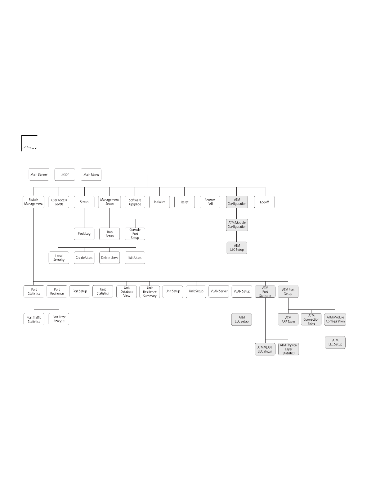
7-2 C
HAPTER
7: A
CCESSING MANAGEMENT FEATURES
Figure7-1
Screen Map
Page 51
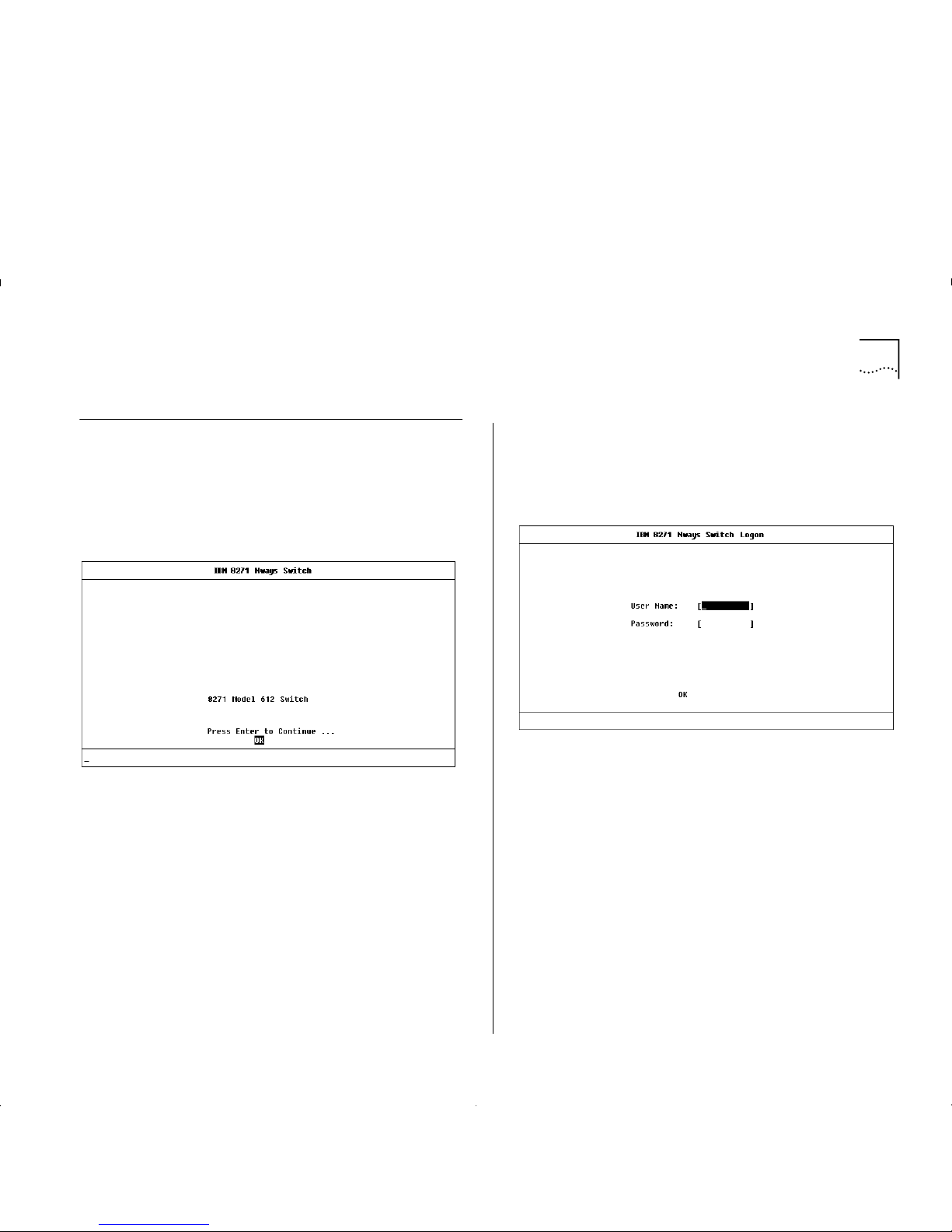
Logging On 7-3
Logging On
1
Connect your terminal to the Console port using a
cross-over cable for a serial line connection.
2
At your terminal, press [Return] two or more times
until the Main Banner is displayed, as shown in
Figure 7-2.
Figure7-2
Main Banner
The Console port will automatically detect the
line-speed (baud rate), and use the following default
settings:
■
auto-baud
■
8 character size (data bits)
■
1 stop bit
■
no parity
Character size, stop bit, flow control, and parity
values cannot be changed.
If your terminal is already setup with these values, the
Main Banner will appear as soon as power-up is
complete.
3
At the Main Banner, press [Return] to display the
Logon screen, as shown in Figure 7-3.
Figure 7-3
Logon Screen
4
Type in your user name and password. Note that they
are both case-sensitive:
■
If you are logging on for the first time (after
installation or initialization), use a default user
name and password to match your access
requirements. We recommend that you use the
default user
security
so that you can access all
functions. The default users are shown in T able 7-1
on page 7-4.
■
If you have been assigned a user name, access level
and password, type in these details.
Page 52

7-4 C
HAPTER
7: A
CCESSING MANAGEMENT FEATURES
To find out which ATM screens can be accessed for
each of the security levels, refer to Appendix B,
“Screen Access Rights”.
For access rights to Switch scr eens, s ee the user guid e
that accompanies your Switch.
When you have logged on, the Main Menu screen is
displayed, as shown in Figure 7-4.
Logging Off
When you have finished using the facility, select the
LOGOFF option from the bottom of the Main Menu.
If you acce ssed t he fac ilit y us in g a Telnet session or
modem, the connection will be closed automatically.
Figure 7-4
Main Screen
Automatic Logout
There is a built-in security timeout on the VT100
interface. If you do not press any keys for three
minutes, a message warns you that the inactivity
timer is about to expire. If you do not press a key
within 10 seconds, the timer will expire and the
screen will be loc ked ; an y d ispl ay e d st atistics will
continue to be updated. When you next press any
key, the display changes to the Auto Logout screen.
The Auto Logout screen asks you to enter your
password again. If the password is correc tl y entered,
the screen that was active when the timer expired is
re-displayed. If you make a mistake entering your
password, you are returned to the Logon screen.
Table 7-1
Default Users
User Na me Defaul t
Password
Access Level
monitor monitor monitor — this user can view, but
not change settings on the screens
they can access.
manager manager manager — this user can view and
change the operational paramete rs
(but not the special/security
features) on the screens they can
access.
security security security — this user can view and
change all manageable parameters
on the screens they can access.
admin (no password) security — this user can view and
change all manageable parameters
on the screens they can access.
Page 53
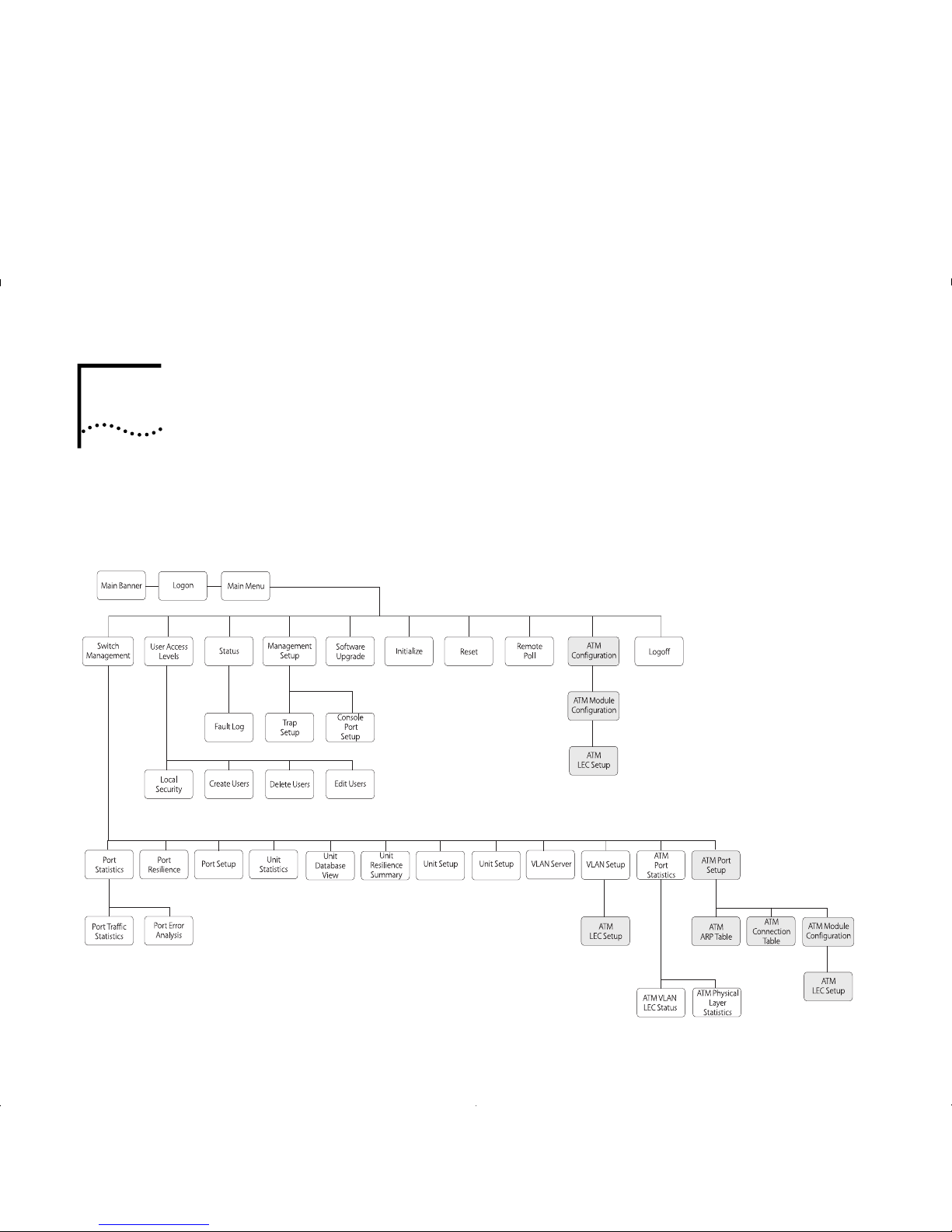
8
M
ANAGING THE
ATM M
ODULE
This chapter describes how to manage the ATM
Module. If you wish to view statistics, r efer to Chapter
9, “Monitoring the ATM Module”.
Figure 8-1 shows the screen map. Management
features are shown in gray to help you locate the
screen you need.
Figure8-1
Management Scr ee n Map
Page 54
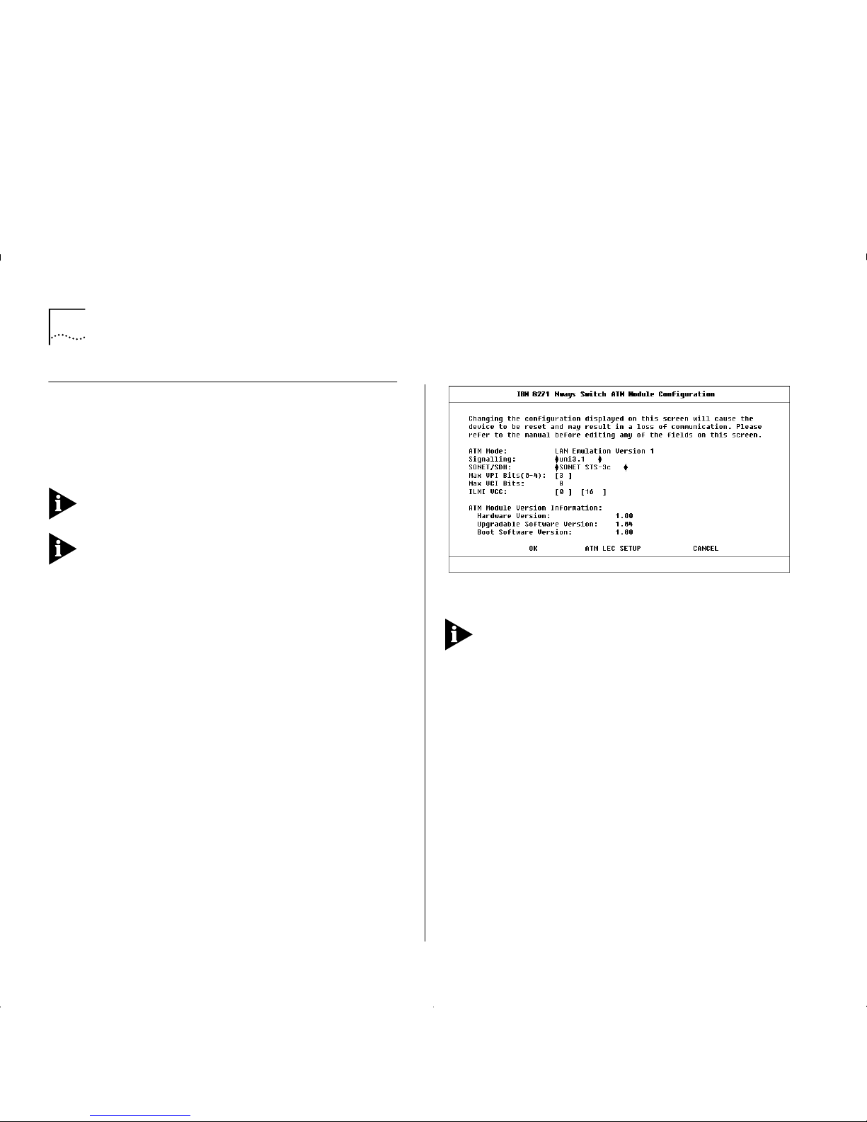
8-2 C
HAPTER
8: M
ANAGING THE
ATM M
ODULE
Configuring a n ATM Port
The ATM Module Configuration Screen shows the
settings and standards used by the ATM Module to
communicate with other devices on the ATM
network.
It is unlikely that you will need to change the value of
these settings once they have been set.
ATTENTION: If you need to change the value of any
of the settings, you may experience a temporary loss
of communication while the device resets. If you do
not need to make any changes, select the CANCEL
button and not the OK button. Selecting the OK
button resets the device.
The ATM Module Configuration screen can be
accessed from the Main Menu or from the ATM Port
Setup screen:
■
Select the ATM CONFIGURATION option from the
Main Menu.
■
Alternatively, if you are already in the ATM Port
Setup Screen, as described in “ATM Port Setup” on
page 8-6, you can select the CONFIG button.
An example of the ATM Module Configuration screen
is shown in Figure 8-2.
Figure 8-2
ATM Module Configuration Screen
Ensure that the A TM Mo dule and the ATM Switch it is
connected to are set up to use the same signalling
and SONET/SDH standards. The two devices should
also use the same ILMI VCC and c ompatible values for
MAX VPI Bits and MAX VCI Bits. If the devices do not
use the same standards, they cannot communicate
with each other.
The following fields are shown on the screen:
ATM Mode
Shows the
ATM Mode
of operation,
which is set to
LAN Emulation Version 1
. The
ATM
Mode
cannot be changed in this release.
Signalling
Specifies the
User-to-Network Interface (UNI)
Signalling
protocol used to communicate with other
devices. Select either
uni3.0
or
uni3.1
standards. The
default is
uni3.1
.
Page 55

Configuring an ATM Port 8-3
SONET/SDH
Specifies the framing us ed. Selec t either
SONET STS-3c
or
SDH STM-1
. The d efau lt is
SONET
STS-3c.
The
MAX VPI Bits
and
MAX VCI Bits
fields described
below, are used to determine how many bits can be
used within each cell header to define the value of
the VPI and VCI. The value of the VPI and VCI fields
identify the connection.
MAX VPI Bits can be used to identify which WAN
connection to use. If you have several remote sites
(London, Manchester and Leeds) you can specify a
unique VPI value which identifies traffic going to that
site. For example, the VPI value for London could be = 1,
Manchester could be = 2, and Leeds could be = 3.
There are 11 b i ts availab l e to b e s h ared between the
VPI and VCI. The default is 3 VPI bits and 8 VCI bits.
You should not normally need to change the defa ul t
settings. The adjacent ATM Switch can read the
settings of these fields via ILMI and normall y
negotiates with the devices to use the lowest common
denominator. If the ATM Switch is non-standar d, you
may need to amend the
MAX VPI Bit s (0 –4 )
field.
MAX VPI Bits (0–4)
Shows the numb er of bi ts a vaila ble
in the cell header that can be used to determine the
value of the VPI. Up to 4 bits are available for use. The
number of bits set offers a range of possible values for
the VPI (as shown within Table 8-1).
Max VCI Bits
The number of bits available for the
VCI is calculated aut omatically, using the foll o wing
equation:
MAX VCI Bits = (11 minus the value of Max VPI Bits)
ILMI VCC
This number identifies the connection used
for
Interim L ocal Managem ent I nterf ace (I LMI)
requests.
The first field identifies the
Virtual Path
and the seco nd
field identifies the
Virtual Channel
.
Y ou should only change the ILMI VCC if the ATM
switch connected to ATM Module does not use the
default ILMI VCC (VPI = 0, VCI = 16).
VCC connections with values 0 (zero) to 31 are
reserved for standard connections and you should
avoid using these values wherever possible.
Hardware Version
Shows the version number of the
ATM Module hardware.
Table 8-1
VPI and Bit Settings
Desired Value of VPI Number of bits
required
00
0 or 1 1
within the range 0
–
32
within the range 0
–
7 3 (default)
within the range 0
–
15 4
Page 56
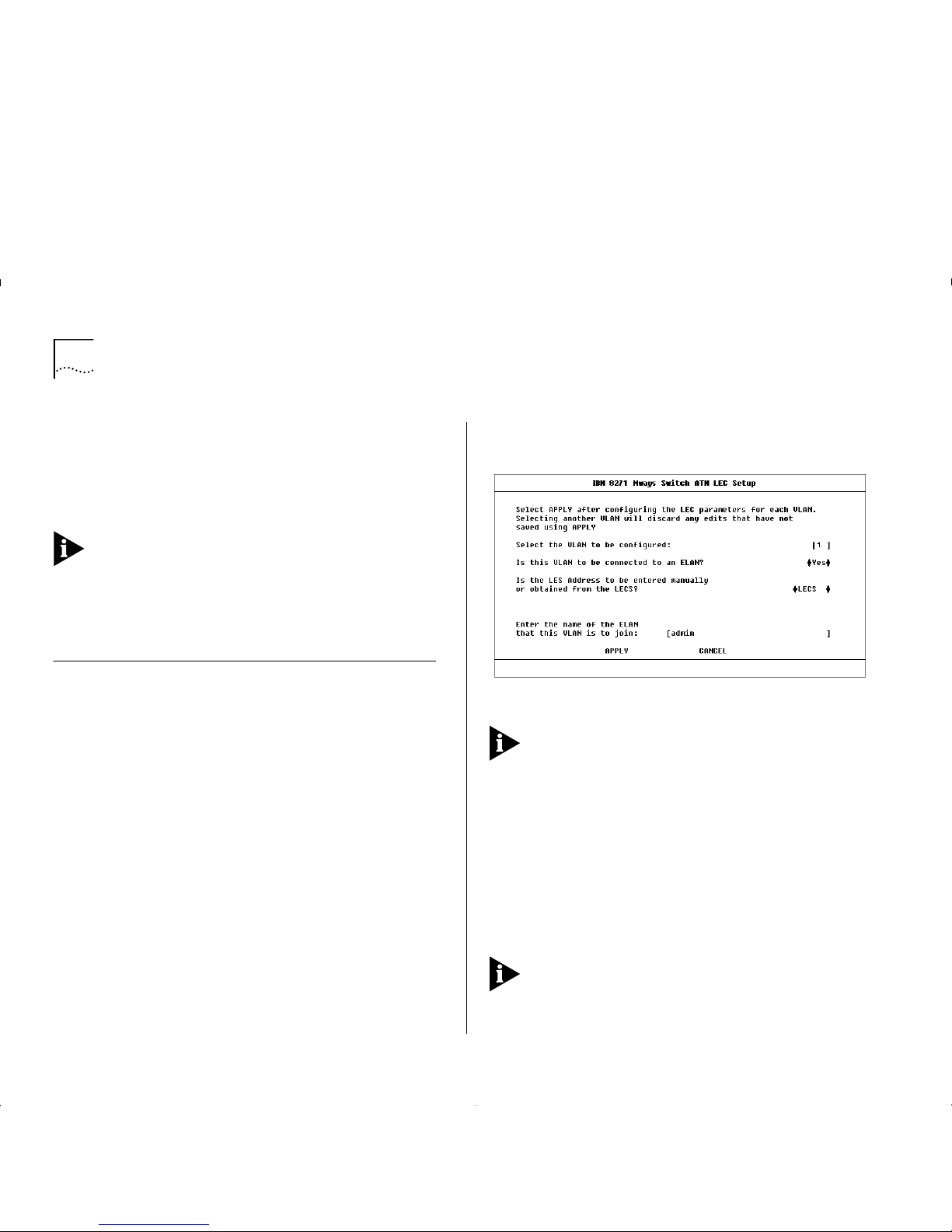
8-4 C
HAPTER
8: M
ANAGING THE
ATM M
ODULE
Upgradable Software Version
Shows the version
number of agent software stored on the ATM Module
(in
Flash EPROM
).
Boot Software Version
This is the version number
of the boot software stored on the ATM Module.
You should keep a copy of these version numbers, in
case you need to contact IBM technical support.
ATM LEC SETUP
This button takes you to the ATM
LEC Setup Screen (as shown in Figure 8-3) which
allows you to extend VLANs into the ATM network.
Extending VLANs into the ATM Network
This section describes how to extend VLANs into the
ATM networ k. T he ATM port can be in one or m ore
VLANs. Each VLAN is associated with a LEC on the A TM
Module, and each LEC is m a pped to an ATM E L AN.
There are two ways to access the ATM LEC Setup
screen:
■
Select the ATM CONFIGURATION option from the
Main Menu. The ATM Module Configuration
screen is displayed, as shown in Figure 8-2 on page
8-2. Select the ATM LEC SETUP button.
■
Alternatively, if you are already in the ATM Port
Setup Screen, as described in “ATM Port Setup” on
page 8-6, you can select the CONFIG button to
display the ATM Module Configuration screen. An
example of the ATM Configuration screen is shown
in Figure 8-2 on page 8-2. Select the ATM LEC
SETUP button.
An example of the ATM LEC Setup screen is shown in
Figure 8-3.
Figure 8-3
ATM LEC Setup Screen
Each time you complete the entry fields for a VLAN
you must select APPLY to apply the changes. As soon
as you select a different VLAN using the VLAN field
any edits not already applied, using the APPLY button,
are lost.
To set up an ATM VLAN:
1
Select the VLAN that you wish to c o nf igure. Enter the
number associated with the VLAN in the designated
field. VLAN to LEC mappings are shown in “ATM Port
Setup” on page 8-6. The default VLAN is VLAN 1, the
admin
VLAN.
Y ou cannot configure VLAN 15 or VLAN 16 when
these VLANs are being used for Auto-Select VLANs
and Spanning Tree, respectively.
Page 57
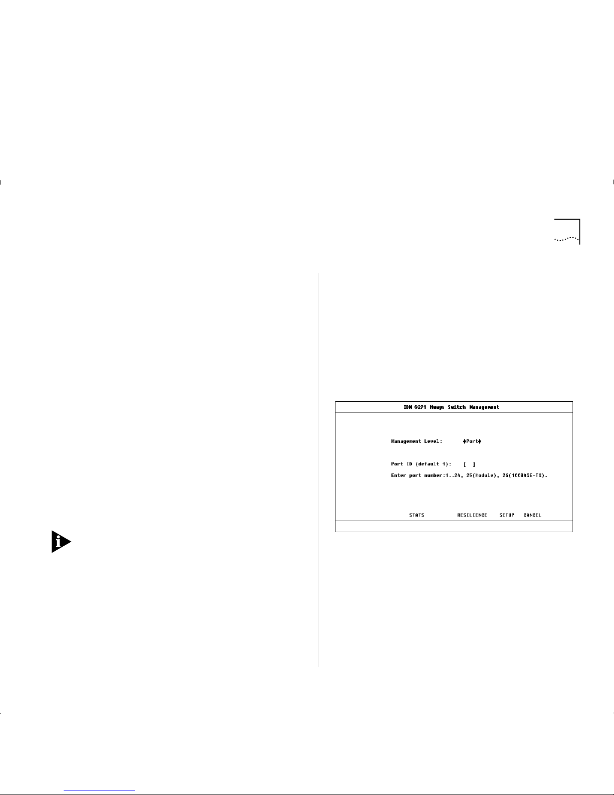
Extending VLANs into the ATM Network 8-5
2
If the VLAN is to be connected to an ELAN, select
Yes
.
If you do not wish the VLAN to be connected to an
ELAN, select No.
3
If there is a LECS cont ro lling ELANs on your network,
it should automatically supply the LES address for the
ELAN, and you should select the
LECS
option.
Only select the
Manual
option if:
■
A LECS is not in use on the network, or
■
The LECS is unaware of the existence of the ELAN
to be joined, or
■
Y ou do not wish the LEC to join a LES controlled by
a specific LECS.
If
Manual
is selected, the L ES addr ess field i s displ ayed
on the screen, and you should enter the A TM address
of the LES associated with the selected VLAN/ELAN.
4
Enter the name of the ELAN that the VLAN is to join.
The ELAN must have already been set up in the ATM
network and be operational.
5
Select the APPLY button.
If the LEC associated with the VLAN is activ e when
APPLY is selected, it will te mporarily be co m e in a ctive
while the changes are applied, and you may
experience a brief loss of communication on that
connection.
Displaying all VLANs
If you wish to display the VLAN membership for all
ports on the Switch, complete the following steps. If
you wish to configure VLANs for the ATM Module
you should use the ATM VLAN Setup screen, as
described in “Extending VLANs into the ATM
Network” on page 8-4.
1
Select the SWITCH MANAGEMENT option from the
Main Menu. The Switch Management screen is
displayed, as shown in Figure 8 -4.
Figure 8-4
Switch Management Screen
2
For the
Management Level
field, select the
VLAN
option and press the [TAB] key. The scr een show n in
Figure 8-5 on pag e 8-6 is displayed.
3
Select the SETUP button to display the VLAN Setup
screen.
An example of the VLAN Setup screen is shown in
Figure 8-6 on page 8-6.
Page 58

8-6 C
HAPTER
8: M
ANAGING THE
ATM M
ODULE
Figure8-5
VLAN Selected Screen
Figure8-6
Switch VLAN Setup Screen
Use [Ctrl]+[D] keys to scroll down the list box to view
the rest of the list, including the ATM port.
The ATM port is shown as
ATM
in the
Type
field, or as
ATM Bp
if it has been set up as a backbone port.
ATM Port Setup
The ATM Port Setup screen allows you to switch the
ATM port on or off, and provides status information
about the state of the port, and the LECs associated
with each of the VLANs. To display the screen:
1
From the Main Menu select SWITCH MANAGEMENT.
The Switch Management screen is d isplayed, as
shown in Figure 8 -4 on page 8-5.
2
For the
Management Level
field, select the
Port
option.
3
Ensure that the ATM port number is entered in the
Port ID
field. For example the ATM port is:
■
Port 13 on an IBM 8271 Nways Ethernet LAN
Switch Model 612 and IBM 8271 Nways Ethernet
LAN Switch Mod el 712
■
Port 25 on IBM 8271 Nways Ethernet LAN Switch
Model 624 and IBM 8271 Nways Ethernet LAN
Switch Model 524
4
Select the SETUP button to display ATM port setup
information. An example of the ATM Po rt Setu p
screen is shown in Figure 8-7 on page 8-7.
Page 59

ATM Port Setup 8-7
Figure8-7
ATM Port Setup Screen
The screen shows the following field s :
Port
Identifies the selected port.
Port Speed
Shows the speed of the port connection.
Port State
Allows you to turn the port on and off. If
you wish to allow traffic to pass through this port,
select the
Enable
option. To prevent traffic passing
through the port, select
Disab le
.
Link State
Indicates whether the communication link
connected to the port is capable of transmitting and
receiving traffic. The states are:
Present
— the link is capable of transferring traffic; if
the ports are also turned on (
enabled
).
Not Available
— the link is not capable of transferring
traffic.
If the li nk is
Not Available
and both devices are
powered-up and operational, there is a physical
problem with your connection. For information about
the cause of problems and possible solutions, see
Table 8-2.
To transmit traffic the port must have a
Port State
of
Enabled
and the
Link State
must be
Present
.
Table 8-2
Link State Troubleshooting Summary
Problem Solution
The connectors at either
end of the lin k have come
loose, or been accidently
pulled out.
Ensure that t he cable is
securely connected to the
port at both ends of the link.
The port at the far end of
the link is
disabled
.
Enable the far end port.
If you have f iber ca ble
with connectors that can
be reversed; the two
connectors at one end of
the fiber cable may be
plugged into the port the
wrong way around.
Check that each cable
connector is connected to the
correct port socket. You may
need to reverse the TX and RX
cable co nnector s at one end of
the link.
The cable is caught under
a heavy object or become
bent out of shape.
Remove any obstructions and
straighte n out a ny kin ks i n t he
cable.
The connector itself is
physically damaged.
Contact your repair center for
advice. Refer to Appendix E,
“Technical Support and
Service” for more deta ils.
Page 60

8-8 C
HAPTER
8: M
ANAGING THE
ATM M
ODULE
Lost Links
The number of times a link was unable to
transmit traffic , that is, the number of times (si nce the
device was reset) that the
Link State
became
Not
Available
.
LEC States
Shows the status of the LEC for each
VLAN. The state can be:
LEC Active
— traffic is passing through the LEC.
LEC Inacti ve
— traffic is not passing through the LEC.
LEC Not in Use
— you have decided not to connect
this VLAN to t he ATM network. The VLAN may still be
in operation within the Switch.
CONFIG
This button takes you to the ATM Module
Configuration screen, which allows you to monitor
and set the standards used by the ATM Module to
communicate with other ATM devices.
The ATM Module Configuration screen is described in
“Configuring an ATM Port” on page 8-2.
ARP TABLE
This button takes you to the ARP Table
screen, which allows you to displays the AT M and
MAC addresses on remote devices. The ARP Table
screen is described in “Mapping Far End MAC
Addresses” on this page.
CONNECTI ON TABLE
This button takes you to the
AT M Connection Table screen, which allows you to
display AT M connection details. The ATM Connection
T able is described in “Displaying an ATM Connection”
on page 8-10.
Mapping Far End MAC Addresses
To communicate with a device, the software must be
able to map the MAC address of the destination
device to the destination edge-device’s ATM address.
This mapping is normally performed by the LEC, and
for the vast majority of devices you do not need to
map MAC addresses to ATM addresses.
The MAC address and ATM address mappings are
stored in the LAN Emulation
ARP Table
(which should
not be confused with the IP ARP Table).
To access the ATM ARP Table screen access the ATM
Port Setup screen, as described in “ATM Port Setup”
on page 8-6, and then select the ARP TABLE button.
An example of the ATM ARP Table screen is shown in
Figure 8-8.
Figure 8-8
ATM ARP Table Screen
Page 61

Mapping Far End MAC Addresses 8-9
VLAN
Allows you t o se lect a VL A N , an d displa y
address information about remote systems connected
to that VLAN.
Port
Identifies the selected port.
Far MAC Address
Shows the MAC Address on the
edge-device at the far end of the connection.
Far ATM Address
Shows the ATM Addres s for the
LEC on the edge-device at the far end of the
connection.
Type
The address entry can be:
Permanent
— The address entries are retained even if
the device is reset or a power-off/on cycle occurs. All
entries made through this screen are stored as
Permanent entries.
Dynamic
— The address entries are aged out after a
set period of time.
Static
— The address entries are discarded when the
switch is reset.
The following fields are used in conjunction with the
buttons at the bottom of the screen:
Far MAC Address
Allows you to type in the MAC
address of end-stations in the network.
Far ATM Address
Allows you to type in the ATM
address of the far end LEC associated with the far end
MAC address.
FIND A TM ADDRESS
This button allows you to l ocate
the A TM address mapped to a specifie d MAC address.
REFRESH
This button updates the view of the ARP
Table to include the latest available information.
INSERT
This button allows you to create a MAC
Address to ATM address mapping in the ARP T able.
DELETE
This button allows you to delete a MAC
address to ATM address mapping in the ARP Table.
Creating a MAC Address to ATM Entry
An easy way to edit an entry is to select a similar e ntry
from the listbox using the spacebar. The far end ATM
and MAC addresses of that entry are shown in the
edit fields. You can then edit the addresses (without
losing or changing the original entry) and select the
INSERT button to create a new entry.
If you cannot select an entry in the listbox (because
you are creating the first entry), use the following
method:
1
In the
Far MAC Address
field, type in the MAC
address of the device to be added to the database.
2
In the
Far ATM Address
field, type in the far end ATM
address.
3
Select the INSERT button.
Page 62

8-10 C
HAPTER
8: M
ANAGING THE
ATM M
ODULE
Finding an Address Entry
1
In the
Far MAC Address
field, type in the MAC
address associated with the ATM addr es s you are
trying to locate.
2
Select the FIND ATM ADDRESS butt on. An asteris k (*)
is shown next to the entry in the database listbox.
Updating Address Entries
To view up-to-date ARP Table entries, select the
REFRESH button.
Deleting an Address Entry
1
Within the listbox, use the spacebar to select the
entry you wish to delete.
2
Select the DELETE button.
Displaying an ATM Connection
This section describes how to create and view ATM
connections in the ATM Connection Table.
To access the ATM Connection Table screen, access
the A TM Port S etup s creen, as d escribed i n “ATM Port
Setup” on page 8-6, and then select the
CONNECTION TABLE but t on. An example of the ATM
Connection T able screen is shown in Figure 8-9.
Figure 8-9
ATM Connection Table Screen
The following fields apply to the listbox:
Port
Identifies the selected port.
VPI:VCI
Identifies the ATM connection by showing
the Virtual Path Identifier and Virtual Circuit Identifier.
End
Identifies whether the near or far end LEC ATM
address is displayed. The options are:
Near
— the details are for the LEC in the A T M Module.
Far
— the details are f or the LEC at the far end of the
connection, for example a LEC in an ATM Switch or
attached ATM device.
Page 63

Setting Up Resilient Links 8-11
ATM Address
Shows the ATM address of LEC for
either the ATM Module or the ATM Switch.
If
Near
is shown in the
End
field, the address is the
address of the LEC in the ATM Module.
If
Far
is shown in the
End
field, it is the add ress of the
LEC in the AT M Switch or attached AT M devi c e at the
far end of the connection.
Type
shows the connection type. The connection
types can be:
Incoming
— the switched virtual circuit was set up by
the Far End LEC.
Outgoing
— the switched virtual circuit was set up by
the Near End LEC.
Reserved
— a permanent virtual circuit has been set up.
VPI:VCI
Allows you to specify th e ATM connection by
typing in the
Virtual Path Identifier
and
Virtual Channel
Identifier
label s. Alt ernat ively, you can u se the sp ace bar
to select and copy a VPI:VCI entry from the listbox.
FIND ATM ADDRESS
This button allows you to find
an A TM Addr es s .
REFRESH
This button allows you to update the view
of ATM connection details.
Finding an ATM Connection
1
In the VPI:VCI field, type in the ATM Connection you
wish to view.
2
Select the FIND ATM ADDRESS button.
Updating Address Entries
To view up-to-date ATM Connection Table details,
select the REFRESH button.
Setting Up Resilient Links
You can protect a critical communication link against
failure by ensuring that, should the main communication
link fail, a standby duplicate communication link
immediately and automatically take s over the task of
the main link.
Each main and standby link pair is referred to as a
resilient li nk pair
.
■
If you wish to setup an ATM port as part of a
resilient link, the other port in the resilient link
must be a
Virtual LAN T runk
(a member of all
VLANs).
■
Typically the ATM Module port is paired with a Fast
Ethernet port on the ATM Switch.
Page 64

8-12 C
HAPTER
8: M
ANAGING THE
ATM M
ODULE
Every 2 minutes the Switch checks the resilien t lin ks
to ensure that the fastest link is the Main (active) link
in the resilient link pair. If the fastest link is not the
Main (acti ve ) lin k, th e Switch automa t ic a lly ma kes it
the Main (active) link, on the condition that:
■
There have not been any
Lost Links
within the last
2 minutes on the faster link that will become the
Main (acti ve ) link.
■
The faster link has been up for 2 minutes.
See the guide which accompanies your Switch for
more details about setting up resilient links.
Upgradin g Sof tw are
The ATM Module has its own software which is
upgraded independently of the Switch software.
You may ne ed to u p grade the softw are on the ATM
Module or Swi tch if I BM produces a new version of the
code, or if the existing code has somehow become
corrupted.
The replacement software image must be held or
placed on a local server which supports the
Trivial File Transfer Protocol (TFTP)
.
Select the SOFTWARE UPGRADE option from the
Main Menu. An example of the Software Upgrade
screen is shown in Figure 8-10.
Figure 8-10
Software Upgrade Screen
Complete the following fields:
Destination
Specify the type of device which you
wish to receive the upgraded software. If you are
upgrading the software on the ATM Module, select
the ATM Module option.
File Name
Specify the name of the upgrade file held
on the server for this type of device.
Server Address
Specify the IP (or IPX) address of the
server holding the upgrade file.
If the upgrade is interrupted, due to a power failure
for example, when the device powers up again, the
MGMT LED is lit green and fla shes to i n dic ate that an
upgrade is taking place, and the Module LED on the
Switch is lit Yellow. The device attempts to download
the last specified software image file.
Page 65

Upgr adin g Sof twar e 8-13
When the OK button is selected, the status of the
upgrade is displayed. The following error and status
messages are avail ab l e:
Error Messages
This sectio n l i st s error messages th at may appear if an
error occurs while downloading a new software
image, and suggests solutions to the problem.
File Not Found
The file you require is not on the specified TF TP server.
You need to specify a different TFTP serv er o r tran s fer
the file you require to the correct directory on the
TFTP server and try again.
Access Violation
You do not have access permissions to this file or
director y. Ensure that the access permissions are
changed.
Load server failed to respond
Communication with the TFTP server could not be
established. Ensure that the workstation on which the
TF TP server is set up is operating and that the network
connection has been set up correctly.
The do w nload co uld not be star ted because of a
lack of resources
Y ou are trying to download a file which requires more
memory tha n is ava ila b le .
The record length differs from that implied by the
value of the record length field.
The file you want to download may have been
corrupted. You should obtain a valid file and try
again.
The record type is not recognized
The file you want to download may have been
corrupted, or is not the correct type of file for the
selected device. You should obtain a valid file and try
again.
Record checksum error
The file you want to download has been corrupted. In
this case you should either retry with the current file,
or obtain a valid file and try again.
The device type in the file is incorrect
The file you are trying to download is not suitable for
the selected device. Ensure that you select either a
different f ile or a dif fer ent devic e, befor e you try again.
The software image is not suitab le for this
version of the hardware
The file you are trying to download is not suitable for
the selected device. Ensure that you select either a
different f ile or a dif fer ent devic e, befor e you try again.
Timeout
The operation to download the software failed after
the operation timed-out. This may be due to a poor
network connection, so try again.
If you see any other messages you should make a
note of the message and contact your supplier.
Page 66

8-14 C
HAPTER
8: M
ANAGING THE
ATM M
ODULE
Status Messages
This section lists status messages that can appear
when you download new software images to a device.
Active
The file is currently being downloaded to the selected
device. Allow time for the download to complete.
Down load succ e ssful
The file you chose to download to the selected device
was downloaded successfully.
Load Paused
The download failed and another attempt will be
made. The download may have failed due to network
re-configuration.
Page 67
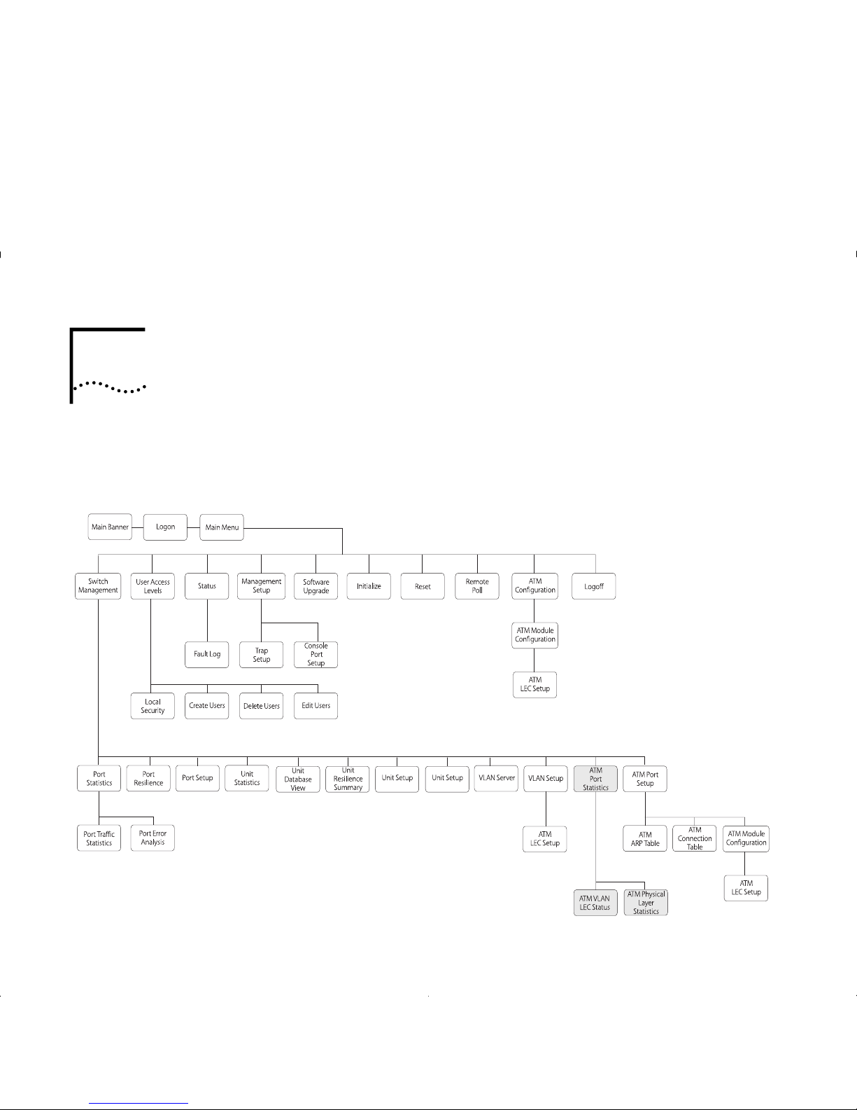
9
M
ONITORING THE
ATM M
ODULE
This chapter describes how to monitor the status and
performance of your ATM Module.
Figure 9-1 shows the screen map. Monitoring screens
are shaded gray to help you locate the screens you
need.
Figure9-1
Status Monitoring Screen Map
Page 68

9-2 C
HAPTER
9: M
ONITORING THE
ATM M
ODULE
Statistics Overview
This section provi des a brief ove rview of the additi onal
statistics that ar e available w hen you install an ATM
Module. Refer to the user guide that accompanies the
Switch for informat ion about the statistics that are
provided by the Switch softwar e.
Table 9-1 groups the available statistics into logical
categories, and tells you where each statistic is located.
ATM Module statistics screens are updated every 2
seconds to show the latest information.
Table 9-1
Statistics and Status Summary
Monitoring Use
Backbone
To estimate the amount of
traffic down the backbon e.
ATM Port Statistics screen:
■
Transmit Bandwidth Used
■
Receive Bandwidth Used
Physical Connection
To check that the physical
connectio n is ope rational.
ATM Physical Layer Statistics
screen:
■
Errored Seconds (Near)
■
Errored Seconds (Far)
■
Severe Errored Sec (Near)
■
Severe Errored Sec (Far)
■
Coding Violations (Near)
■
Coding Violations (Far)
■
Unavailable Seconds (Near)
■
Unavailable Seconds (Far)
ATM Port Statistics screen:
■
Receive Errors
VLAN/ELAN
To monitor the state of the
LEC to LES set up process.
To monitor Ethernet traffic
on the VLAN.
ATM VLAN LEC Stat us Screen:
■
LEC State
■
LEC ELAN Name
■
LEC ATM Address
■
Last LEC Failure Reason
■
LEC Operation at Failure
■
Fram es Received
■
Frames Transmitted
■
Octets Received
■
Octets Transmitted
ATM
To monitor ATM traffic.
ATM Port Statistics screen:
■
Cells Received
■
Cells Transmitted
■
Errored Cells
■
Bad VCC Received
AAL5
To monitor AAL5 traffic.
ATM Port Statistics screen:
■
Fram es Received
■
Frames Transmitted
■
Octets Received
■
Octets Transmitted
■
Errored Frames
■
Discarded Frames
Table 9-1
Statistics and Status Summary
Monitoring Use
Page 69
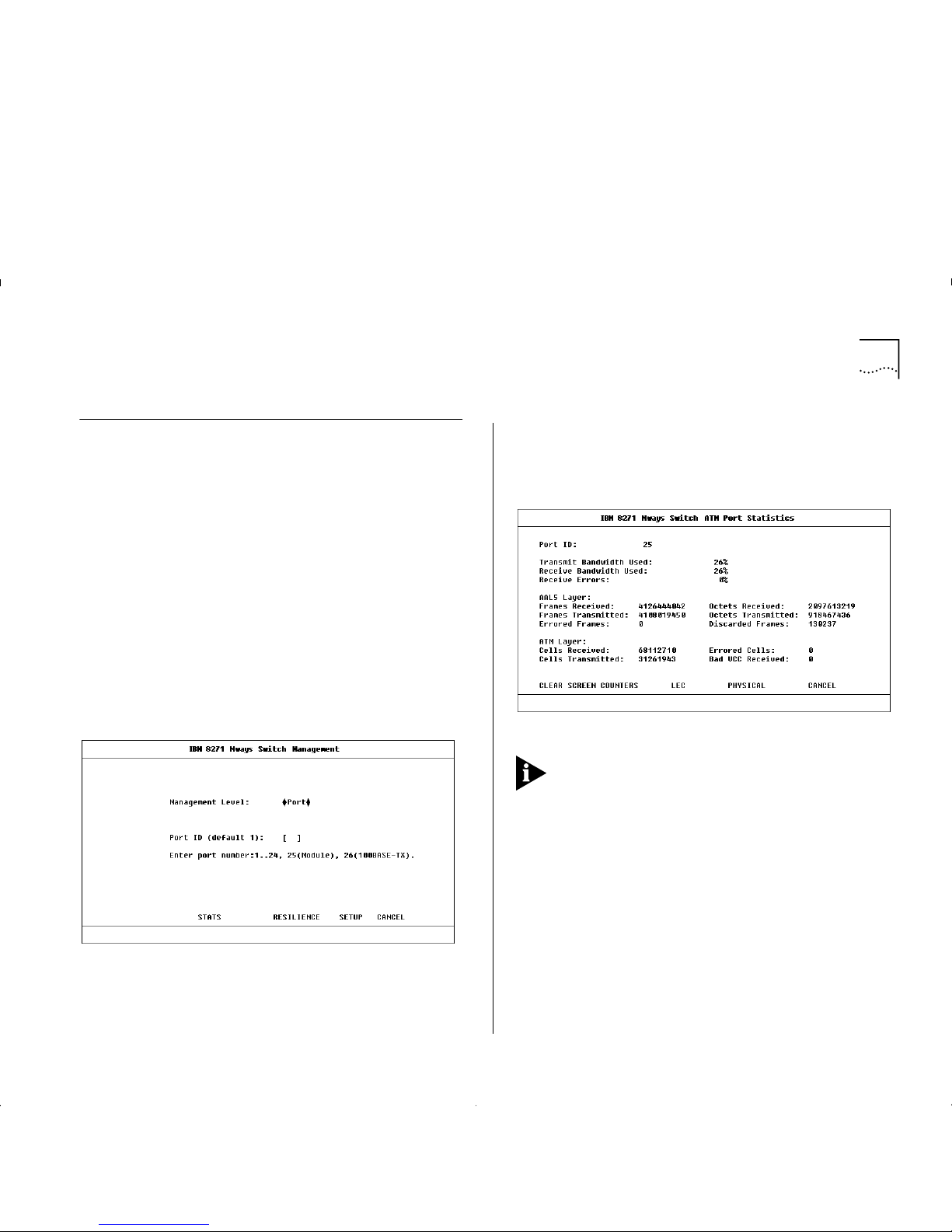
ATM Port Statistics 9-3
ATM Port Statistics
The A TM Port Statistics screen provi d es a top level
summary of traffic levels on the ATM Port. You can
use the summary to estimate the amount of traffic on
your network backbone, and to check the health of
the incoming connection. Statistics are grouped into:
■
AT M Port Bandwidth use and incoming connection
health.
■
AAL5 layer health and use.
■
ATM layer health and use.
To view the ATM Port statistics:
1
Select the SWITCH MANAGEMENT option from th e
Main Menu. The Switch Management screen is
displayed, as shown in Figure 9-2.
Figure9-2
Switch Management Screen
2
Enter the number of t he ATM port in the
Port ID
field.
3
Select the STATS b ut ton to display the ATM Port
Statistics screen.
4
An example of the A TM Port Statistics scr een is shown
in Figure 9-3.
Figure 9-3
ATM Port Statistics Screen
The figures shown for each statistic on this screen
include ATM management traffic and normal
Ethernet traffic.
The ATM Port Statistics screen displays the following
fields:
Port ID
Identifies the currently selected port.
Transmit Bandwidth Used
Shows the percentage of
available transmit bandwidth that is currently being
used by transmit cells.
Receive Bandwid th U sed
Shows the percentage of
available receive bandwidth that is currently being
used by received cells.
Page 70

9-4 C
HAPTER
9: M
ONITORING THE
ATM M
ODULE
Receive Errors
Shows the percentage of cells
received that have errors. For example, cells received
with corrupted header information (
Header Error
Control – HEC
).
Receive Errors indicate that there is something wrong
with the link, and you should check for the following
faults:
■
Weak transmitter. Contact your supplier or
Technical Support, as described in Appendix E.
■
The optic fiber cable is too long or does not meet
other technical specifications. Check the cable
against th e te ch nical spec ifica t io n given in
Appendix C, “ATM Module Technical Specifications”.
■
The optic fiber connectors are dirty. To clean the
connectors, follow the instructions given in
“Cleaning Dirty Fiber Optic Connectors”, on page
D-24.
■
If there is no traffic on the port, but there are
Receive Errors, the SONET
Scramble
techniques on
the ATM Module and ATM Switch are probably
incompatible. Ensure that the SONET standards
used are the same for the ATM Module and the
ATM Switch.
The screen al so shows the AAL5 lay er sta tistic s. AA L is
a set of protocols that translate user traffic from
higher-layer applications/protocols into small, fixed
size cells, and reassembles them into the higher level
frame format at the destination device. The ATM
Module supports AAL5. The screen shows the
following AAL5 Layer statistics:
Frames Received
The number of frames received per
second at the AAL5 interface for all traffic types (data
and control).
Frames Transmitted
The number of frames
transmitted per second at the AAL5 interface for all
traffic types (data and control).
Errored Frames
The number of frames received that
contain an error.
Octets Received
The number of Ethernet octets
received at the AAL5 interface.
Octets Transmitted
The number of Ethernet octets
transmitted at the AAL5 interface.
Discarded Frames
The number of frames discarded
at the AAL5 interface due to lack of resources.
Page 71
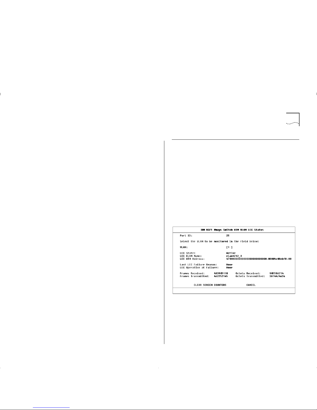
ATM VLAN LEC Status 9-5
The screen also shows the following ATM statisti cs:
Cells Receiv e d
The number of ATM cells received by
the port.
Cells Transmitted
The number of ATM cells
transmitted per second by the port.
Errored Cells
The number of ATM cells that contain
an error, for example, cells that have
Header Error
Control (HEC)
errors.
Bad VCC Received
The number of cells received
where the specified connection is not recognized by
the A TM Module (that is, the connection is not shown
in the ATM Module Connection Table).
The following buttons are available on this screen:
CLEAR SCREEN COUNTERS
T o make it easier to note
the changes in statistic values, you can use this button
to reset the value of statistics shown on the screen to
zero. Resetting the values shown on the screen does
not reset the statistic values stored on this device.
LEC
This button takes you to the ATM VLAN LEC
Status screen, w hich all ows you to monitor th e health
of LECs and identifies the cause of any connection
failures. The A TM VLAN LEC Status scr een is descr ibed
in “ATM VLAN LEC Status” on this page.
PHYSICAL
This button takes y ou to the Physical L ayer
Statistics Screen, which allows you to monitor the
health of the physical connection, and is more useful
in a WAN environment. The Physical Layer Statistics
Screen is described in “ATM Physical Layer Statistics”
on page 9-10.
ATM VLAN LEC Status
The A TM VLAN LE C Statu s scr een show s LEC stat isti cs
for the ATM port. You can use the status information
to monitor the health of a VLAN’s LEC and to track
down the cause of any pr oblems. Y ou can also m onitor
the amount of Ethernet traffic on the selected VLAN.
To access VLAN statistics, first access the ATM Port
Statistics screen, as descri bed i n “ ATM Port Statistics”
on page 9-3, and then select the LEC button.
An example of the ATM VLAN LEC Status screen is
shown in Figure 9-4.
Figure 9-4
ATM VLAN LEC Status Screen
Page 72

9-6 C
HAPTER
9: M
ONITORING THE
ATM M
ODULE
Port ID
Identifies the currently selected port.
VLAN
Allows you to select the VLAN you wish to
monitor. The default is VLAN 1. If you wish to review
the state of all VLANs on the ATM Module, see “ATM
Port Setup” on page 8-6.
LEC State
Shows the state of the LEC to LES
communication. The states are shown in Table 9-2.
LEC ELAN Name
Shows the name of the ELAN that
the VLAN/LE C ha s join e d.
LEC ATM Address
Shows the ATM Address of the
LEC associated with the selected VLAN.
Last LEC Failure Reason
If the LEC configuration
fails, the last know failure st ate is show n. The fail ure
state can be used to identify the cause of the failure.
The failure state and possible causes are shown in
Table 9-3.
Table 9-2
LEC State Summary
LEC State Description
Active The LEC is in use.
Inactive The LEC is not in use. The LEC may be
inactive because it has not been able
to establish communication with the
LES and BUS, or because the ATM port
has been disabled by management.
Not in Use You have specified that the LEC is not
required at the present time.
Table 9-3
Last LEC Failure Reason
State Possible Causes Possible Solutions
None
The LEC is either
inactive or has
successfully completed
the operation.
None required.
Timeout
A task could not be
completed within
its allotted time
frame.
The s oftware has been
set up to use a LECS,
but a LECS is either not
present on t he ne twork
or broken.
The LES for th e EL AN is
not functioning
correctly
If there is a LECS on
your network, ensure
that it is operational
and on part of the
network that can be
accessed by the ATM
Module.
If a LECS is not present
on the network, you
must enter the LES
Address for each ELAN
manually using the A TM
VLAN Setup Scr een
(see “Extending VLA Ns
into the ATM Network”
on page 8-4).
Contact Technical
Support.
Undefined Error
An error has
occurred but no
cause can be
identified.
Unknown. Contact Technical
Support.
Version Not
Supported
LANE 1.0 not
supported.
The LANE services you
are trying to connect
to, do not support
LANE version 1.0.
Ensure that the LANE
Services use LAN E 1.0 .
(continued)
Page 73

ATM VLAN LEC Status 9-7
Invalid Request
Parameters
The LES/LE CS has
rejected a requ est
from the LEC
because the request
parameters were
incompatible with
the ELAN.
The LE C may b e
requesting a resource
that is on an ELAN
which has a different
LAN type to the LEC.
The frame size used
could be wrong .
Check the underlying
media for both the
ELAN a nd the LEC
requesting the service.
Check the frame sizes
being used.
Duplicate LAN
Destination
A destinatio n sour ce
MAC add ress
duplicates a
previously registered
MAC add ress.
The LES has received a
request from a LEC
which contains a MAC
address already
registered t o another
LEC on the same ELAN.
You may have
accide ntally en tered the
same MAC addresses
twice.
Ensu re that MAC
addresses are unique.
Table 9-3
Last LEC Failure R eason
State Possible Cau ses Possible Solu ti o ns
Duplicated ATM
Address
A source ATM
addres s duplic a tes a
previously
registered ATM
address.
The LES has received a
request fr om a LEC
which cont ains an ATM
address already
register ed to another
LEC on the same ELAN.
For example, if a LES is
faulty, when a LEC
disconnects from the
LES, the LES might fail
to register the chan ge.
When the LEC tries to
rejoin the LES, the LES
still has that LEC’s ATM
address in its database ,
and thinks that two
devices have the same
ATM address.
You may have
accidentally entered
the same ATM
addresses twice.
Ensure that AT M
addresses are unique.
Check the LES
database for dup li ca te
addresses.
(continued)
Table 9-3
Last LEC Failure Reason
State Possible Causes Possible Solutions
Page 74

9-8 C
HAPTER
9: M
ONITORING THE
ATM M
ODULE
Insufficient
Resources
There are
insufficient
resources to grant a
request.
Too many connections
have been requeste d
and the tables used by
the LES may be full,
and the connection
cannot be set up.
The ATM Switch is busy
and cannot provide
LECS functionality.
There is a mismatch
between the VPI/ VCI
range supported by
adjacent ATM devices.
Example:
If Switch A supports
VPI/VCI values 7:511
and Switch B only
supports values up to
7:255, w hen Si gn all i ng
tries to set up a
connect ion using the
VPI/VCI value 7:256,
Switch B rejects the
connection.
You may wish to
consider extending or
restructuring your
network.
Use a separate ATM
Switch for LECS
functionality.
Make the MAX VPI/VCI
Bits compatible.
Access Denied
The L ES has denied
the LEC access to
the ELAN for
security reasons.
The LEC is t rying to j oin
an ELAN that it is not
allowed to access.
Check your LANE
Services setup.
(continued)
Table 9-3
Last LEC Failure R eason
State Possible Cau ses Possible Solu ti o ns
Invalid
Requestor ID
The
LEC Identifier
(LECID)
is not zero,
or is not recognized
as this LEC’s LECID.
There is a problem with
the L EC so ftware.
Contact 3Com
Support.
Invalid LAN
Destination
You are trying to
register a multicast
addre ss with th e L E S.
You may have
configured an illegal
Local Administration
Address.
Check that the Local
Administrat ion
Address is valid.
Local Administration
Addre ss setup is
beyond the scope of
this guide.
Invalid ATM
Address
Source or
destination ATM
address is not in a
recognized format.
The ATM address field
may have been
corrupted or not in the
corr ect format.
For e xamp le, it m ay be
in E.164 when OSI
N-SAP address coding
is required.
Contact your supplier
or 3Com Technical
Support.
No Configuration
The LECS/LES does
not recognize the
LEC or the
requested ELAN
The MAC address may
be invalid.
The LEC may be
requesting a resource
that is on an ELAN
whic h has a different
LAN type to the LEC.
You may have entered
an invalid ELAN name.
Check that each MAC
address on y our
network is unique.
Check the LAN type
used.
Check that the ELAN
name is correct, and
the ELAN has been set
up correctly.
Table 9-3
Last LEC Failure Reason
State Possible Causes Possible Solutions
Page 75

ATM VLAN LEC Status 9-9
LEC Operation at Failure
Identifies the operation
that was being carried out when the LEC setup failed.
This field should be used in conjunction with the Last
LEC Failure Reason to identify the cause of the
problem. The possible operations are shown in
Table 9-4.
LE_CONFIGURE
Error
This state may be
given to refuse a
service without
giving a specific
reason.
The information
provided by the LEC
may be invalid.
You may have entered
an invalid ELAN name.
As this state is used to
indicate a range of
problems , you shou ld
chec k the other states
and solutions
described in this table.
If this does not resolve
the problem c ontact
3Com Technical
Support.
Check that the ELAN
name is correct, and
the ELAN has bee n set
up correctly.
Insufficient
Information
The LEC has not
provided sufficient
information to
allow the LECS to
assign it to a spec ific
ELAN.
The MAC address may
be invalid.
The LE C may b e
requesting a resource
that is on an ELAN
which has a different
LAN type to the LEC.
You may have entered
an invalid ELAN name.
Check that each MAC
address on your
network is unique.
Check the LAN type
used.
Check that the ELAN
name is correct, and
the ELAN has bee n set
up correctly.
Table 9-3
Last LEC Failure R eason
State Possible Cau ses Possible Solu ti o ns
Table 9-4
LEC O peration at Failure
Operation Description
None
There are no known operation failures.
Calling LECS
The LEC is tryi ng to connect to the
LECS to receive LANE configuration
information.
Reading
Configuration
from LECS
The LEC receives configuration
information from the LECS in
preparation for joining the LES.
Joining LES
The LEC is trying to join the ELAN by
registering itself with the LES that
controls that ELAN.
When the LEC has joined the LES, it is
given a unique
LAN Emulation Client
Identifier (LECID)
, knows the Emulated
LAN’s maxim um frame size , and knows
its LAN type (either Ethernet or Token
Ring).
Initial Registration
After joining, a LEC can register any
number of MAC addresses and/or
Route Descriptors (for Token Ring
implementations).
Connecting to BUS
In order to establish a connection to
the
Broadcast and Unknown Server
(BUS)
the LEC requir es the broadcast
address. It requests the broadcast
address from the LES.
Operational
The LEC is now part of the ELAN.
Page 76

9-10 C
HAPTER
9: M
ONITORING THE
ATM M
ODULE
Frames Received
The number of Ethernet frames
received by the LEC.
Frames Transmitted
The number of Ethernet frames
transmitted by the LEC.
Octets Received
The number of Ethernet octets
received by the LEC.
Octets Transmitted
The number of Ethernet octets
transmitted by the LEC.
If you see the following symptoms, there may be a
problem at the ATM Switch end of the connection:
The LEC is
active
and the
LEC Operation at Failure
is
None
, but the frames or octets counters are showing
zero.
If you have followed the troubleshooting instructions
in this section and within Appendix D, and you still
have a problem, contact IBM Technical Support. Refer
to Appendix E for details.
The following button is available on this screen:
CLEAR SCREEN COUNTERS
T o make it easier to note
the changes in statistic values, you can use this button
to reset the value of statistics shown on the screen to
zero. Resetting the values shown on the screen does
not reset the statistic values stored on this device.
ATM Physical Layer Statistics
The Physical Layer Statistics screen shows
SONET STS-3c
and
SDH STM-1
error statistics. These statistics are used
to track down problems with the physical connection,
and are more useful in a WAN environment.
To access Phy s ical Layer statistics, first access the ATM
Port Statistics screen, as described in “ATM Port
Statistics” on page 9-3, and then select the PHYSICAL
button.
An example of the Physical Layer Statistics screen is
shown in Figure 9-5 on page 9-11, and the statistics
are described in the following text.
Port
Identifies the currently selected port.
OCD State
Shows the
Out of Cell Delineation (OCD)
state. The OCD State is set to
Fail
when seven
consecutive cells have had Header Error Control
violations. This implies that the cell has been
corrupted and that there is probably a hardware
problem with the ATM Module or ATM Swit c h .
The OCD State is only set to OK when six good cells
are received by the ATM Module followed by
approximately 10 seconds of good signal from the
ATM fiber optic cable.
Page 77

ATM Physical Layer Statistics 9-11
Figure9-5
Physical Layer Statistics
Current Sample
Specifies the number of seconds
elapsed within the current sampling period.
SONET/SDH counters are acc u mul ated over a perio d
of 15 minutes (900 seconds). At the end of the 15
minute sampling period, the software stores the
results of the current sampling period, and resets the
values shown o n the sc reen to zero.
The results of the previous 96 sampling periods can
be accessed through the SONET MIB using a MIB
Browser.
Physical Layer statistics are broken down into the
following layers:
■
Path
— The Path Layer deals with the mapping of
ATM cells to SONET or SDH frames. The ATM
Module supports 1 path.
■
Line
— The Line Layer provides synchronization
and multiplexing functions for the Path Layer
across the physical medium.
■
Section
— The Section Layer deals with framing,
scrambling, and section error monitoring.
Physical Layer errors are measured in units called
Seconds:
each
Second
is a second in time
.
In the following statistics a
second
is cons id e red
errored if it contains a
Coding Violation
.
A
coding violation
occurs when the parity check in
the SONET or SDH frame indicates that the cell
payload has been corrupted.
A
second
is considered severely errored if it contains
16
coding violations
for a path or section, or 32
coding violations
for a line counter.
A
second
is unavailable if 10 continuous severely
errored
seconds
are seen at the ATM interface.
A
second
becomes available agai n, when 10
consecutive
seconds
are received that are not severely
errored.
Page 78

9-12 C
HAPTER
9: M
ONITORING THE
ATM M
ODULE
The following statistics ar e ava ilab l e:
Errored Seconds (Near)
The number of errored
seconds
at the ATM Module end of the connection.
Errored Seconds (Far)
The number of
seconds
at the
ATM Switch end of the connection.
Severe Errored Sec (Near)
The number of severely
errored
seconds
at the ATM Module end of the
connection.
Severe Errored Sec (Far)
The number of severely
errored
seconds
at the ATM Swit ch end of the
connection.
Coding Vi ol ati ons (Near)
The number of c
oding
violations
that have occurred at the A TM Module end
of the connection.
Coding Vi ol ati ons (Far)
The number of
coding
violations
that have occurred at the ATM Switch end
of the physical connection.
Unavailable Seconds (Near)
The number of
seconds
that were unavailable at the ATM interface
on the ATM Module.
Unavailable Seconds (Far)
The number of
seconds
that were unavailable at the ATM interface on the
ATM Sw itch.
Using Physical Layer Statistics to Troubleshoot
This section describes how to use the physical layer
statistics to track and resolve problems.
If no values are shown on the screen, the problem
probably lies with the ATM Switch rather than the
ATM Module. Follow the troubleshooting information
in the user guide that accompanies your ATM Switch.
High values usually i ndicate that the SON ET stand ard s
are incompatibl e, or th at there is a fau lt on the c ab l e.
Use the following troubleshooting suggestions to try
and resolve the problem:
1
Check that the ports at both end of the link are
enabled
.
2
Check that the cable is sec ur ely connected to th e port
at both ends of the link.
3
Check each end of the cable to ensure that each of
the fiber connectors is correctly connected. If you
have connectors that can be reversed, you may need
to reverse the TX and RX cable connectors at one end
of the link.
4
Make sure that the cable does not exceed the cable
length or other technical specifications. Check the
cable against the technical specification given in
Appendix C.
5
Remove any obstructions and straighten out any kinks
in the cable.
6
If you suspect that the fiber optic connector is dirty,
refer to “Cleaning Dirty Fiber Optic Connectors” on
page D-24.
Page 79

ATM Physical Layer Statistics 9-13
7
If you suspect that the fiber optic cable is not
working, replace the cable with a cable known to be
working, and check the Link Status LED.
8
Check that the cable has not been accidently plugged
into an FDDI connector at one end of the connection.
9
Check that the ATM Module and ATM Switch are
using compatible transmit clocking options.
10
Check that the Line Rate settings on the two devices
are com patible.
11
If there is still a problem, contact your repair center
for advice. For more details, refer to Appendix E.
Page 80

9-14 C
HAPTER
9: M
ONITORING THE
ATM M
ODULE
Page 81
A
S
AFETY INFORMATION
You must read the following safety information
before carrying out any installation or remov al of
components, or any ma intenance procedures on
the Switch.
Safety No tices
Safety notices are printed throughout this manual.
DANGER
notices warn you of conditions or p rocedures that can result in death or severe personal
injury. CAUTION notices warn you o f conditions or
procedures that can cause personal injury that is neither lethal not extremely hazardous.
World Trade Safety Information
Some countries require the safety information contained in publications to be presented in their
national languages. Before using an English-language publication to set up , install, or operate this
IBM product, you first should become familiar with
the related safety information.
DANGER: Before you begin to install this product,
read the safety information in Caution: Safety Infor-
mation – Read This First, SD21-0030. This booklet
describes safe procedures for cabling a nd plugging
in electrical equipment.
Varning — livs fara: Innan du börj a installera den
här produkten bör du läsa säkerhetsinformtionen i
dokumentet Varning: Säkerhetsföreskrifter – Läs
detta först, SD21-0030. Där beskrivs hur du på ett
säkert sätt ansluter elektrisk utrustning.
Fare: Før du begynner å installere dette produktet,
må du lese sikkerhetsinformasjonen i Advars el: Si k-
kerhetsinformasjon – Les dette først, SD21-0030
som beskriver sikkerhetsrutinene for kabling og
tilkobling av elektrisk utstyr.
Fare: Før du installerer dette produkt, skal du læ se
sikkerhedsforskrifterne i NB: Sikkerhedsforskrifter –
Læs dette først, SD21-0030. Vejiedningen beskriver
den fremgangsmåde, d u skal bruge ve d tilslutning
af kabier og udstyr.
Gevarr: Voordat u begint met de installatie van dit
produkt, moet u eerst de veiligheidsinstructies lezen
in de brochure PAS OP! Veiligheidsinstructie s – Lees
dit eerst, SD21-0030. Hierin wordt beschreven hoe u
electrische apparatuur op een veilige manier moet
bekabelen en aansluiten.
Page 82
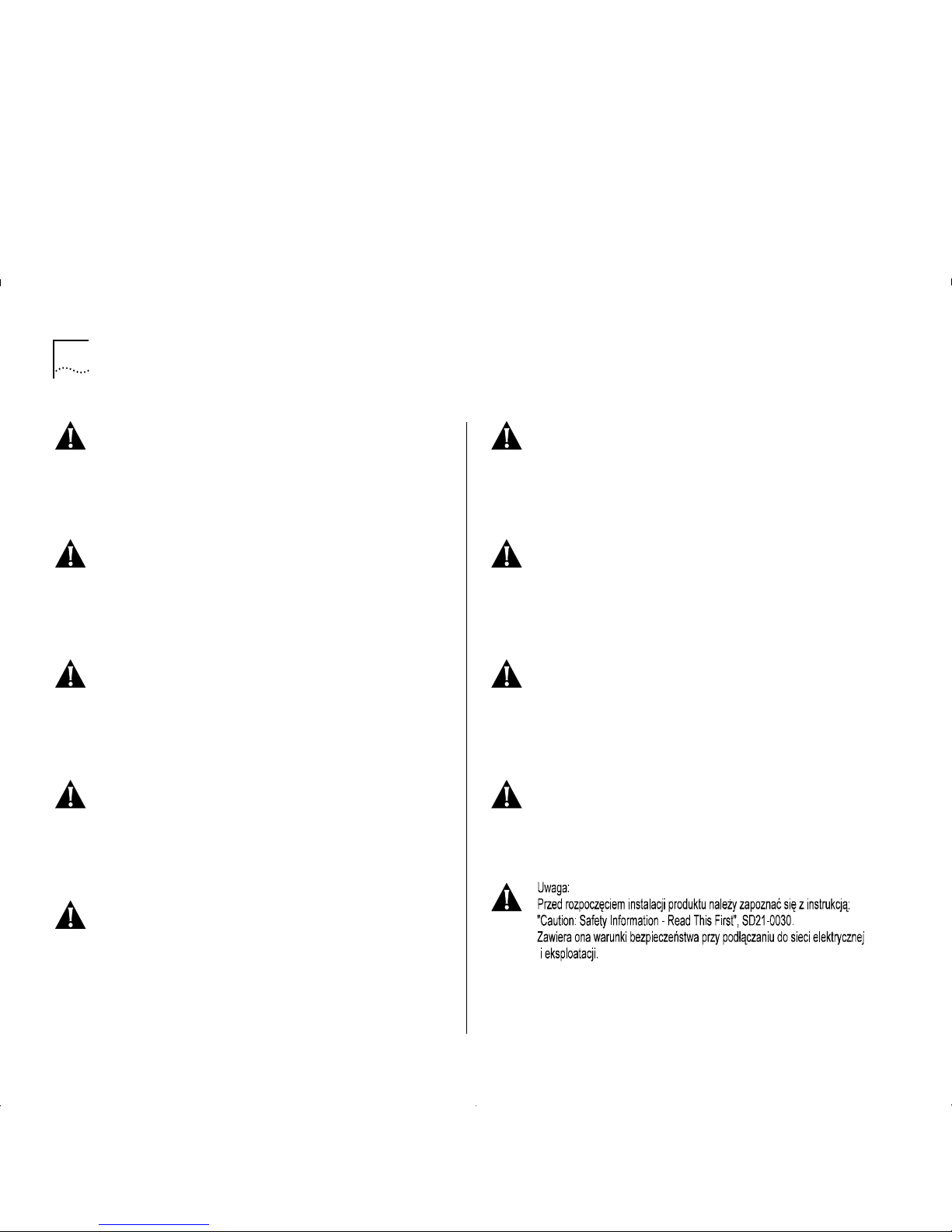
A-2 A
PPENDIX
A: S
AFETY INFORMATION
Gevarr:
Voordat u begint met het installeren van dit
produkt, dient u eerst de veiligheidsrichtlijnen te
lezen die zijn vermeld in d e publikatie
Caution:
Safety Informtion – Read This First
, SD21-0030. In
dit boekje vindt u veilige p rocedures voor het
aansluiten van elektrische appratuur.
Vo rs icht:
Bevor mit der Installation des Produktes
begonnen wird, die Sicherheitshinweise in
Achtung:
Sicherheitsinformationen – Bitte zuerst lesen
, IBM
Form SD21-0030. Diese Veröffentlichung beschreibt die Sicherheitsvorkehrungen für das Verkabeln und Anschließen elktrische r Geräte.
Danger:
Avant d'installer le présent produit, con-
sultez le livret
Attention: Informations pour la sécu-
rité – Lisez-moi d'abord,
SD21-0030, qu i décrit les
procédures à respecter pour effectuer les opérations
de câblage et brancher les équipements électriques
en toute sécurité.
Danger:
Avant de procéder à l'installation de ce
produit, lisez d'abord les consignes de sécurité dans
la brochure
ATTENTION: Consignes de sécurité – A
lire au préalable
, SD21-0030. Cette brochure décrit
les procédures pour câbler et co nnecter les appareils électriques en toute sécurité.
Pericolo:
prima di iniziare l'installazione di questo
prodotto, l eggere le inform azioni relative alla
sicurezza riportate nell'opuscolo
Attenzion: Infor-
mazioni di sicurezza – Prime informazioni da leggere
in cui sono descritte le procedure per il cablaggio ed
il collegamento di apparecchiature elettriche.
Perigo:
Antes de iniciar a instalação deste produto,
leia as informações de segurança
Cuidado: Infor-
mações de Segurança – Leia Primeiro
, SD21-0030.
Este documento descreve como efectuar, de um
modo seguro, as ligações eléctricas dos equipamentos.
Peligro:
Antes de empezar a instalar este producto,
lea la informaci ón de segurid ad en
Ate nc ión: In fo r-
mación de Seguridad – Lea Esto Primero
,
SD21-0030. Este doc umento describe lo s procedimientos de seguridad para cablear y e nchufar equipos eléctricos.
Perigo:
Antes de começ ar a instalar este prod uto,
leia as informações de segurança contidas em
Cuidado: Informações Sobre Segurança – Leia Isto
Primeiro
, SD21-0030. Esse folhet o descreve procedimentos de seguranç a para a insta lação de cabos e
conexões em equip amentos elétricos.
VARRA:
Ennen kuin aloitat tämän tuotteen asen-
nuks en, lu e julk aisuss a
Varoitus: Turvaohjeet – Lue
tämä ensin
, SD21-0030, olevat turvaohj eet. Tässä
kirjasessa on ohjeet siitä, miten sähkölaitteet kaapeloidaan ja kytketään turvallisesti.
Page 83
Safety Notices A-3
Vigyázat: Mielôtt megkezdi a berendezés üzembe
helyezését, olvassa el a Caution: Safety Information
– Read This First, SD21-0030 könyvecskében leírt
biztonság i információk at. Ez a könyv leír ja, milyen
biztonsági intézkedéseket kell megtenni az elektromos berendezés huzalozásakor illetve csatlakoztatásakor.
Pozor: Preden zaènete z i nstalacijo tega produkta
prebertte poglavje: 'Opozorilo: Informacije o
varnem rokovanju - preberi pred uporabo ,”
SD21-0030. To poglavje opisuje pravilne postopke
za kabliranje,
Page 84
A-4 A
PPENDIX
A: S
AFETY INFORMATION
ATTENTION
DANGER:
Installat ion an d remo val of t he un it must
be carried out by qualified personnel only.
DANGER:
L'insta llation et l'enlè vemen t de l' unité
doivent être faits seulement par le personnel qualifié.
DANGER:
Ein- und Ausbau des Gerätes ist nur von
Fachpersonal vorzunehmen.
Gevaar!
De eenheid m ag alleen worden geïn-
stalleerd of verwijderd doorbevoegde person en.
Perigo:
A instalação e remoção da unidade deve ser
feita apenas porpessoal especializado.
Fare!
Installation og afmontering af enheden skal
udføres afuddannet personale.
Gevaar:
Installat ie en verwijde ring v an de e enheid
moet uitsluitend worden uitgevoerd door getraind
personeel.
Verra:
Yksikön saavat asentaa ja irrottaa vain tähän
koulutetut henkilöt.
Pericolo:
L’installazione e la rimozione d ell’unità
devono essere eseguite esclusivamente da personale specializzato.
Fare:
Det er bare kvalifisert personale som kan
installere og ta ut enheten.
Perigo:
A instalação e a remoção da unidade
devem ser efectuadas apenas por pessoal qualificado.
Peligro:
La instalación y extracción de la unidad
debe efectuarseúnicamente por personal cualificado.
Fara:
Installation och flyttning av enheten måste
utföras av utbildad personal.
Class 1
LED Product
Class 1
LED Product
LED
Klasse 1
LED
Klasse 1
Luokan 1
LEDLAITE
Luokan 1
LEDLAITE
Appareil a LED
de Classe 1
Appareil a LED
de Classe 1
Neodstraňujte desky modulů, pokud je připojeno napájení.
Page 85
Safety Notices A-5
DANGER: This unit operates under SELV conditions
(Safety Extra Low Voltage) according to IEC 950, the
conditions of which are maintained only if the
equipment to which it is connected is also operational under SELV.
DANGER: Cette unité marche sous les condition s
SELV (Safety Extra Low Voltage) conformément à IEC
950, ces conditions sont m aintenues seulement si le
matériel auquel elle est branchée, est aussi en
exploitation sous SELV.
DANGER: Das Gerät wird mit Sicherheits-Kleinspannung nach IEC 950 (SELV = Safety Extra Low Voltage) betrieben. Angeschloßen werden können nur
Geräte, die ebenfalls nach SELV b etrieben werden.
Gevarr: D eze eenheid w erkt onder SELV (Safety
Extra Low Voltage) volgens IEC 950, waarvan de
voorwaarden alleen beho uden blijven indien d e
apparatuur waarop het is aangesloten, ook onder
SELV werkt.
Perigo: Esta unidade funciona sob condições SELV
(Safety Extra Low Voltage) de acordo co m IEC 950
mas, essa situação é mantida apenas se oequipamento ao qual ela est conectada também funcionar
sob a condição SELV.
Fare! Denne enh ed fungerer ved svagstrøm i he nhold til betingelsern ei IEC 950. D isse betingelser
overholdes kun, hvis det udstyr, enheden er sluttet
til, også fungerer ved svagstrøm.
Монтаж и демонтаж оборудования должен выполнять
только квалифицированный персонал.
Page 86
A-6 A
PPENDIX
A: S
AFETY INFORMATION
Gervaar:
Deze eenheid werkt onder extra lage
spanning (SELV, Safety Extra Low Voltage) volgens
norm IEC 950. Er wo rdt uitsluitend aan dez e norm
voldaan zolang de appara tuur waarmee de eenhe id
is verbonden, ook werkt on der SELV.
Vaara:
Tämä yksikkö sisältää kansainvälisen turvastandardin IEC 950 mukaisia SELV (Safety Extra LowVoltage) -suojajännitepiirejä. Yksikkö täyttää
standardissa kuvatut ehdot vain, jos laite, jo honyksikkö liitetään, käyttää SELV-piirejä.
Pericolo:
Questa unità funziona i n condizioni di
bassissima tensionedi sicurezza (SELV, Safety Extra
Low Voltage) secondo l’IEC 950.Tali condizioni so no
rispettate solo se anche l’apparecchiaturaa cui
l’unità è collegata funziona in SELV.
Fare:
Dette utstyret drives med strøm fra kretser
med ekstra lav spenning (SELV-kretser) i henhold til
standarden IEC 950. Denne s penningen
opprettholdes kun dersom utsty ret som det er
koblet til, også drives av såkalte SELV-kretser.
Perigo:
Esta unidade funciona sob condições SELV
(Safety Extra LowVoltage - Tensão Muito Baixa, de
Segurança), de acordo com anorma IEC 950. O
estabelecido nesta norma só pode rá se r m antidos e o
equipamento ao qual a unidade for ligada também
funcionarsob aquelas condições SELV.
Peligro:
Esta unidad opera bajo condiciones SELV
(Safety Extra Low Voltage /Voltaje Extra Bajo de Seguridad) de acuerdo a la norma IEC 950, sibien tales
condiciones únicam ente se mantienen s i el equipo
alque se conec tan es asimismo opera cional bajo
SELV.
Fara:
Den här enheten arbetar under villkoren för
kyddsklenspänning (Safety Extra Low Voltage) enligt
IEC 950. Dessa villkor uppfylls endast om utrustning
till vilken enheten ansluts också arbetar med skyddsklenspänning.
Page 87
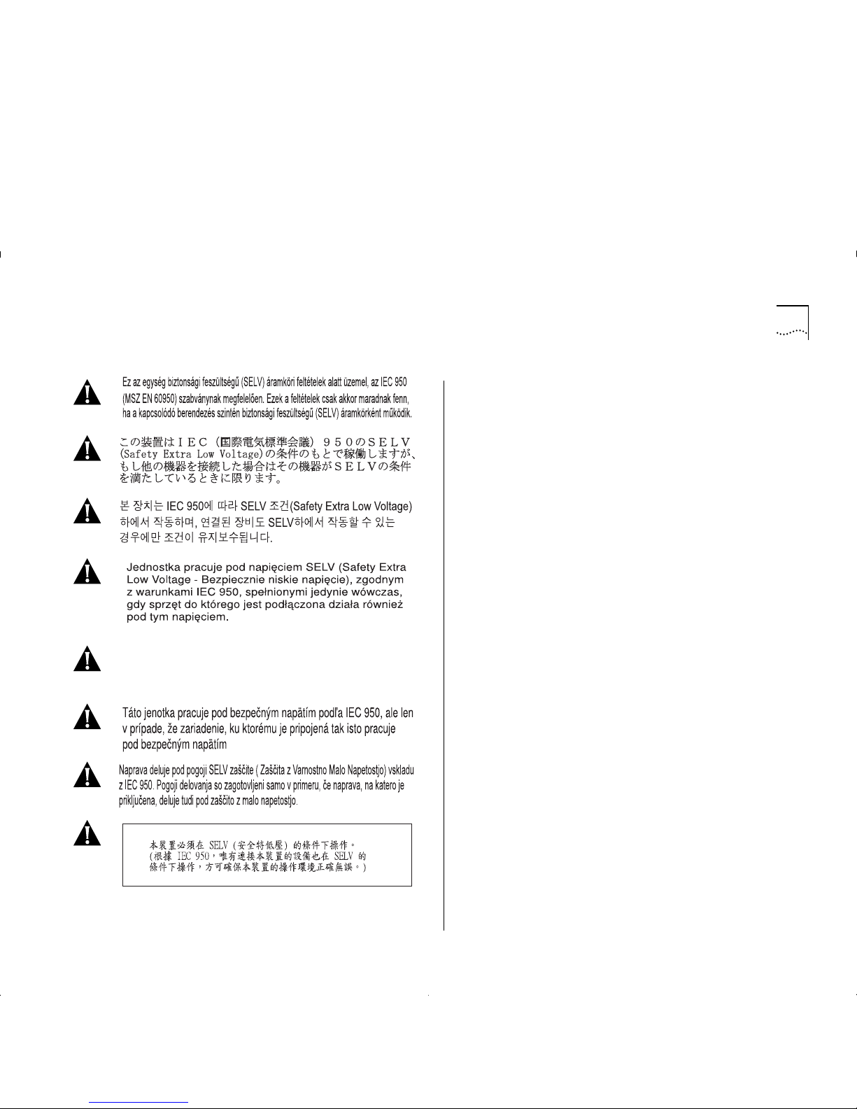
Safety Notices A-7
Это устройство работает по стандарту IEC 950 в условиях
Безопасно низкого напряжения (SELV) только при условии,
что все оборудование в цепи отвечает стандартам SELV.
Page 88

A-8 A
PPENDIX
A: S
AFETY INFORMATION
Page 89
B
S
CREEN
A
CCESS
R
IGHTS
This appendix lists the security access level you must
have to be able to access the ATM Module local
management screens, and lists the type of action that
can be performed for each security level.
This appendix only covers screens specifically
associated with ATM functionality. Refer to the user
guide which accompanies your IBM 8271 Nways
Ethernet LAN Switch for additional screen access
rights.
The general actions that can be performed by users
for each of the security access levels is as follows:
Security/Specialist — read and write
Manager — read and write
Monitor/Secure Monitor — read only
Table B- 1 s hows the access rights required for each of
the A TM screens.
Table B-1
Access Rights
Screen Available to access level...
ATM Mod ul e
Configur ati o n
Manager
Security
ATM LEC Setup
Security
Manager
ATM ARP Table
Manager
Monitor
Secu rit y
ATM Port Setup
Manager
Monitor
Security
ATM Connection Table
Manager
Monitor
Security
ATM Physic al Layer
Manager
Monitor
Security
ATM Port Statistics
Manager
Monitor
Security
ATM VLAN LEC Status
Manager
Monitor
Secu rity
Page 90

B-2 A
PPENDIX
B: S
CREEN ACCESS RIGHTS
Page 91

C
ATM M
ODULE TECHNICAL SPECIFICATIONS
Environmental Specifications
The environmental specifications for the ATM Module
are shown in Table C-1.
ATM Cable Specification
In addition to adhering to your local standards, all
cables must conform to:
The American National Standard ATM Physical Layer
Medium Dependent (PMD) standard,
ISO.166-1990,
American National Standards Institute.
The ATM cable you connect to the ATM Module must
conform to the Multi-Mode Fiber (MMF-PMD)
standard defined by ANSI x.3-166-1992.
IBM supports 62.5/125mm Multi-Mode Fiber
(MMF-PMD). The maximum inter-station distance
(including device-to-network connectors) should not
exceed 2 kilometers (1.25 miles).
Table C-2 on page C-2 shows the cable specifications
for standard multi-mode cabling.
Table C-1
Environ men tal Spec i fications
Operating Temperature 0 to 50° C / 32 to 122°F
Operating Humidity 10–95% relative humidity,
non-condensing
Standards EN60068 (IEC68)
Safety
Agency Certifications UL 1950,
EN60950,
CSA 22.2 No. 950,
ECMA 97
Electromagnetic Emissions
(Agency Certification)
EN55022 Class B,
FCC Part 15 Class A,
C108.8-M1983 Class A,
EN 50082-1 (IEC801 Parts 2-5),
EN60555 Part 2
Page 92

C-2 A
PPENDIX
C: ATM M
ODULE TECHNICAL SPECIFICATIONS
Maximum attenuation includes attenuation and the
loss induced by other components such as
connectors, splices, and the mating of unlike fiber
types. Although some 2km (1.25 miles) cables have a
total attenuation of less than 11dB, the 2km (1.25
miles) inter-station distance m ust be m ain tai ne d to
comply with modal bandwidth requirements.
The maximum attenuation value in this table is based
on a cable diameter of 62.5, 80 or 100mm.
Table C-3 shows the alternative Multi-Mode fiber
types that can be used.
If you are using fiber with a diameter of 50mm and
have IBM 8271 Nways Ethernet LAN Switch
equipment at both ends of the link, substitute 8.0dB
for the maximum attenuation. If IBM 8271 Nways
Ethernet LAN Switch equipment is only at one end,
substitute 6.0dB for the maximum attenuation value.
If you are using equipment at the end of the link from
a vendor other than IBM, you must perform a
separate loss budget analysis. Contact the vendor(s)
for values to use in your analysis.
Does the Cable Provide Sufficient Bandwidth?
Bandwidth for multi-mode fiber is referred to as
modal bandwidth because it varies with the modal
field (or core diameter) of the fiber.
Modal bandwidth is specified in units of MHz.km,
which indicates the amount of bandwidth supported
by the fiber for a 1km (0.625 miles) distance. Your
cable must have a Modal bandwidth of 500MHz,
which allows the cable to support end-to-end
bandwidth of 250MHz at the maximum 2km (1.25
miles) distan c e.
Table C-2
Standard Multi-mode Cable Specifications
Specification Description
Core 62.5µm diameter
Cladding 125µm diameter nominal
122µm minimum
128µm maximum
Numerical aperture 0.275
Maximum attenuation 11dB (including 1dB allowed for
reflection and dispersion penalties)
Modal bandwidth 500 MHz.km
Maximum distance between
nodes
2km (1.25 miles)
Output power (from transceiver) -20dB minimum
-14dB maximum
Receiver power -31dB minimum sensitivity
-14dB maximum sensi t ivity
Table C-3
Alternative Multi-mode Cable Specifications
Core (Pm) Cladding (Pm) Numerical Aperture
50 125 0.20
50 125 0.22
85 125 0.28
100 140 0.29
Page 93

ATM Cabl e Spec ifica tio n C-3
To check that the bandwidth of your fiber is within an
acceptable range:
1
Divide the amount of bandwidth available according
to the fiber specification by the total length of fiber
(km).
2
If the result is lower th an 25 0M H z, the link may be
prone to bit errors. You should shorten the length of
the fiber or use a different fiber until the result of the
calculation reaches 250MHz.
Example:
A cable with modal bandwidth of 500 MHz.km will
have 250 MHz of bandwidth at 2km (1.25 miles).
The same cable would have a 500MHz of bandwidth
at 1km (0.625 miles).
A fiber cable with a bandwidth specification of
200 MHz.km would have only 100MHz of bandwidth
at 2km (1.25 miles), which would not support ATM.
In this case, another type of fiber which has a
bandwidth of 155MHz would be required.
Page 94

C-4 A
PPENDIX
C: ATM M
ODULE TECHNICAL SPECIFICATIONS
Page 95

D
T
ROUBLESHOOTING
How to Use this Guide to Troubleshoot
This troubleshooting section describes how to identify
the cause of a problem and suggests possible
solutions. Troubleshooting has been divided into four
sections.
■
Using LEDs
LEDs on the Switch and ATM Module provide
valuable status information that can be used for
troubleshooting. You may find it useful to
familiarize yourself with these LEDs before reading
the troubleshooting suggestions in the following
sections.
■
Identify the Problem
Use this section when you do not know the cause
of the problem.
■
Solving a known Problem
Use this section when you have detected a
problem, and want to look up possible solutions.
You should read this troubleshooting information
in conjunction with the troubleshooting provided
in the user guide that accompanies your Switch.
■
Cleaning D irt y Fiber Optic Conn ecto rs
This section tells you how to clean the fiber optic
connectors on the ATM Module and connecting
cables.
If you have problems that are not addressed by
troubleshooting information in this guide, contact
IBM Technical Support, or your service person. For
Technical Support information refer to Appendix E.
Page 96

D-2 A
PPENDIX
D: T
ROUBLESHOOTING
Using LEDs
Table D-1 describes the LEDs on the Switch, and Table
D-2 describes the LEDs on the ATM Module.
Table D-1
LEDs on the Switch
LED Name Color/State Indicates
MGMT
(On the front of
the Switch)
Green
Green
flashing
Yellow
Yellow
flashing
OFF
Switch and ATM Module are
operating normally.
Switch or ATM Module is either
downloading software or initializing,
(which includes a
Power On Self Test
).
Switch has failed its
Power On Self
Test (POST
)
ATM Module failed its
Power On Self
Test (POST)
.
No power to the Switch.
Module
(On the front of
the Switch)
Green
Green
flashing
Green
(long on,
short off)
Yellow
Yellow
flashing
OFF
ATM port enabled; link present.
ATM port disabled; link present.
This LED will flash until all configured
LECs have successfully joined their
ELANs.
ATM agent softwar e is not installed
correctly, or the ATM Module has
failed its POST (if the MGMT LED is
flashing yellow).
Switch has not recogni ze d the ATM
Module.
The ATM Module is not ins tall e d, or a
link is not present on the ATM port,
or the ATM Switch is not on.
Table D-2
LEDs on the ATM Module
LED Name Color/State Indicates
Far End Status
(On ATM Module)
Green
OFF
(and Link
Status LED is
Green)
OFF
(and Link
Status LED is
OFF)
The ATM Switch has not
detected an error on the ATM
Module’s
transmit
link.
The AT M Switch at the far end
of the connection has detected a
problem with th e A TM Module ’s
transmit
connecti on, and
notified the ATM Modu le. For
example, the
transmit
half o f t he
ATM Module’s cable has been
disconnected at either the ATM
Module end or ATM Switch end
of the c onn ection.
The cable between the ATM
Module and ATM Switch has
been disconne cte d.
Link Status
(On ATM Module)
Green
OFF
A link i s prese nt on th e ATM
port, and the port is receiving
valid SONET frames.
The Link is not present on the
ATM Port.
TX
(On ATM Module)
Yellow
OFF
The ATM port is transmitting
Ethernet, LANE, Signalling or
control frames.
The A TM port is not transmitt ing
cells.
RX
(On ATM Module)
Yellow
OFF
The A TM p ort is r ec eivin g d ata
cells.
The ATM port is not receiving
incoming cells.
Page 97

Identifying the Problem D-3
Identifying the Problem
This section describes how to identify problems, and
suggests possible solutions. Flow diagrams have been
used to summarize the process, and each step shown
in the flow diagrams is described in more detail in the
text.
This section assumes that the following conditions
have been met:
■
The A TM Modul e has been inst al led correctly, as
described in Chapter 6, “Installing and Setting Up
the Module”.
■
The device is “alive” when pinged, and can be
accessed through the local management screens.
■
Both the ATM Module and the ATM Switch or
attached ATM device are using the same physical
standard; eith er
SONET STS-3c
or
SDH STM-1
.
Page 98
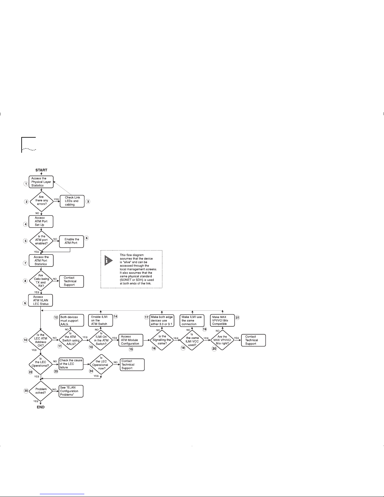
D-4 A
PPENDIX
D: T
ROUBLESHOOTING
Figure D-1
Troubleshooting Flow Diagram
Page 99
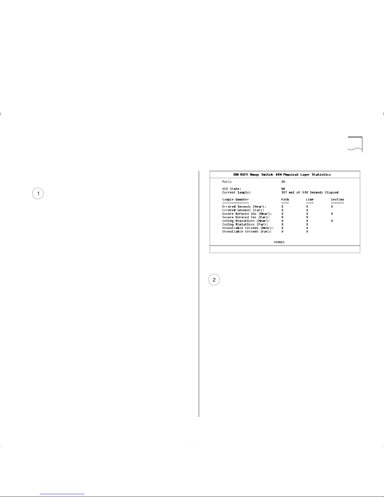
Identifying the Problem D-5
The numbered st ep s in th is se ct ion relate to the
numbered steps shown in Figure D-1.
Access the Physical Layer Statistics Screen
a
Select the SWITCH MANAGEMENT option from
the Main Menu. The S witc h Management s cr een i s
displayed.
b
Ensure that the Port option is selected in the
Management Level field.
c
Ensure that the ATM port number is entered in the
Port ID field. For example the ATM port is:
■
Port 13 on an IBM 8271 Nways Ethernet LAN
Switch Model 612 and IBM 8271 Nways
Ethernet LAN Switch Model 712
■
Port 25 on an IBM 8271 Nways Ethernet LAN
Switch Model 624 and IBM 8271 Nways
Ethernet LAN Switch Model 524
d
Select the STATS button. The AT M Port Statistics
screen is displa ye d.
e
Select the PHYSICAL button to display the SONET or
SDH physical layer statistics. An example of the
Physical Layer Statistics screen is shown in Figure D-2.
Figure D-2
ATM Phys ical Layer Statistics
Are there Physical Layer Errors?
a
If the OCD State field is set to
Fail
, there is a
problem with the physical connection.
b
If there are a lot of errors, there is a problem with
the physical connection.
Is the error rate high?
Yes
— go to step 3.
No
— go to step 4.
Page 100

D-6 A
PPENDIX
D: T
ROUBLESHOOTING
Check the Physical Connections
Check that the Link Status and Far End Status LEDs on
the ATM Module are ON and lit green. If one or both
of the LEDs is not lit, there is a problem with the
physical connection. Follow the troubleshooting
information below:
a
Ensure that both devices are powered-up, and that
the ports at both ends of the link are enabled.
b
Ensure that the cable is securely connected to the
port at both ends of the link.
c
Check each end of the cable to ensure that each of
the fiber connectors is correctly connected. If your
connectors can be reversed, you may need to
reverse the TX and RX cable connectors at one end
of the link.
d
Remove any objects obstructing the cable and
straighten out any kinks in the cable.
e
If you suspect that the fiber optic connector is
dirty, see “Cleaning Dirty Fiber Optic Connectors”
in this sectio n.
f
Check that your cable meets the specifications
described in “ATM Cable Specification” on page
C-1
g
Replace the cable with a cable known to be
working, and check the Link Status LED again.
h
If there is still a problem, contact your repair center
for advice. For more details, see Appendix E.
Access the ATM Port Setup Screen
a
Select the SWITCH MANAGEMENT option from
the Main Menu. The Switch Management screen is
displayed.
b
Ensure that the
Port
option is sele cted in the
Management Level
fiel d .
c
Ensure that the ATM port number is entered in the
Port ID
field. For example the ATM port is:
■
Port 13 on an IBM 8271 Nways Ethernet LAN
Switch Model 612 and IBM 8271 Nways
Ethernet LAN Switch Model 712
■
Port 25 on an IBM 8271 Nways Ethernet LAN
Switch Model 624 and IBM 8271 Nways
Ethernet LAN Switch Model 524
d
Select the SETUP button to display ATM port setup
information. An example of the The A TM Por t
Setup screen is shown in Figure D-3.
Figure D-3
ATM Port Setup Screen
 Loading...