

Page 1

International Technical Support Organization
8260 Multiprotocol Intelligent Switching Hub
May 1995
GG24-4370-00
Page 2

Page 3

IBML
International Technical Support Organization
8260 Multiprotocol Intelligent Switching Hub
May 1995
GG24-4370-00
Page 4

Take Note!
Before using this information and the product it supports, be sure to read the general information under
“Special Notices” on page xv.
First Edition (May 1995)
This edition applies to the 8260 Multiprotocol Intelligent Switching Hub family.
Order publications through your IBM representative or the IBM branch office serving your locality. Publications
are not stocked at the address given below.
An ITSO Technical Bulletin Evaluation Form for reader′s feedback appears facing Chapter 1. If the form has been
removed, comments may be addressed to:
IBM Corporation, International Technical Support Organization
Dept. 545 Building 657
P.O. Box 12195
Research Triangle Park, NC 27709-2195
When you send information to IBM, you grant IBM a non-exclusive right to use or distribute the information in any
way it believes appropriate without incurring any obligation to you.
Copyright International Business Machines Corporation 1995. All rights reserved.
Note to U.S. Government Users — Documentation related to restricted rights — Use, duplication or disclosure is
subject to restrictions set forth in GSA ADP Schedule Contract with IBM Corp.
Page 5

Abstract
This document describes the IBM 8260 Multiprotocol Intelligent Hub. It provides
information about the 8260 architecture as well as how to install, configure and
manage the 8260 Ethernet and token-ring media modules.
This document was written for customers, systems engineers, network
professionals and technical support personnel. Some knowledge of local area
networks, token-ring and Ethernet architecture is assumed.
(327 pages)
Copyright IBM Corp. 1995 iii
Page 6

iv 8260 Multiprotocol Intelligent Switching Hub
Page 7

Contents
Abstract . . . . . . . . . . . . . . . . . . . . . . . . . . . . . . . . . . . . . . . . . . iii
Special Notices
Preface
How This Document is Organized
Related Publications
. . . . . . . . . . . . . . . . . . . . . . . . . . . . . . . . . . . . . . xv
. . . . . . . . . . . . . . . . . . . . . . . . . . . . . . . . . . . . . . . . . xvii
......................... xvii
. . . . . . . . . . . . . . . . . . . . . . . . . . . . . . . . xviii
International Technical Support Organization Publications
Acknowledgments
Chapter 1. An Overview of the IBM 8260 Hub
1.1 Introduction
1.2 8260 Hardware Description
1.2.1 IBM 8260 Model 017
1.2.2 The Intelligent Cooling Subsystem
1.2.3 8260 Model 010
1.3 8260 Modules and Daughter Cards
1.3.1 Ethernet Modules
1.3.2 Token-Ring Modules
1.3.3 Management and Controller Modules
Chapter 2. Backplane Architecture
2.1 LAN Segments on the Backplane
2.2 Ethernet Segments on the Backplane
2.2.1 Digital Collision Detection
2.2.2 Analog Collision Detection
2.2.3 Statistics Collection
2.3 Token-Ring Segments on the Backplane
2.4 FDDI Segments on the Backplane
2.5 Network Allocations on the 8260 Backplane
2.5.1 Management Buses
. . . . . . . . . . . . . . . . . . . . . . . . . . . . . . . . . . . xix
................... 1
. . . . . . . . . . . . . . . . . . . . . . . . . . . . . . . . . . . . . 1
............................ 3
.............................. 3
..................... 7
................................ 7
....................... 8
. . . . . . . . . . . . . . . . . . . . . . . . . . . . . . . 8
. . . . . . . . . . . . . . . . . . . . . . . . . . . . . 9
................... 10
. . . . . . . . . . . . . . . . . . . . . . . . . . 13
........................ 13
...................... 15
.......................... 19
.......................... 19
. . . . . . . . . . . . . . . . . . . . . . . . . . . . . . 19
.................... 19
........................ 22
.................. 23
. . . . . . . . . . . . . . . . . . . . . . . . . . . . . . 26
.......... xviii
Chapter 3. 8260 Fault Tolerant Controller Module
3.1 8260 Fault Tolerant Controller Module Overview
3.1.1 The Controller Module Front Panel
3.1.2 Controller Module Fault Tolerance
3.1.3 Installing and Configuring the Fault Tolerant Controller Module
3.1.4 8260 Fault Tolerant Controller Module Considerations
Chapter 4. 8260 Distributed Management Architecture
4.1 8260 Distributed Management Architecture
4.1.1 I P Addressing for DMM
........................... 38
4.2 The Distributed Management Module (DMM)
4.2.1 Unpacking and Installing the DMM
4.2.2 DMM LED Indicators
4.2.3 Console and Auxiliary Ports
4.2.4 Configuring the DMM
............................. 40
......................... 41
............................. 43
4.3 The EC-DMM (Ethernet Carrier - Distributed Management Module)
4.3.1 Installing the EC-DMM
4.3.2 EC-DMM LED Description
4.4 MAC Daughter Cards
Copyright IBM Corp. 1995 v
............................ 59
.......................... 60
............................... 61
................. 29
............... 29
.................... 30
..................... 32
... 32
......... 33
.............. 35
.................. 35
................. 39
..................... 39
.... 58
Page 8

4.4.1 Ethernet MAC Daughter Card (E-MAC) .................. 64
4.4.2 Token-Ring MAC Daughter Card (T-MAC)
4.5 Managing 8260 Using DMM and 8250 xMM
4.5.1 Managing 8260 with DMM
4.5.2 Managing 8260 with 8250 xMM
.......................... 70
....................... 70
4.6 Overview of Management and Control Commands
................ 66
.................. 69
.............. 71
Chapter 5. 8260 Intelligent Power Management Subsystem
5.1 Intelligent Power Management Subsystem
5.2 Power Class
5.3 Configuring 8260 Power Supplies
5.3.1 Non-Fault Tolerant Mode
5.3.2 Fault Tolerant Mode
5.4 Managing Power in the 8260
. . . . . . . . . . . . . . . . . . . . . . . . . . . . . . . . . . . . . 74
........................ 76
........................... 78
............................. 79
........................... 81
.................. 73
5.4.1 Installing 8260 Module in an 8260 Managed by DMM
5.4.2 Installing 8260 Module in an 8260 Not Managed by DMM
5.4.3 Installing 8250 Module in a Hub Managed by DMM
5.4.4 Installing 8250 Module in a Hub Not Managed by DMM
5.5 Controlling Power to the 8260 Modules
5.6 Power Management Considerations
5.7 Power Management Scenarios
.......................... 86
5.8 Installing the 8260 Power Supply
Chapter 6. 8260 Intelligent Cooling Subsystem
6.1 Intelligent Cooling Subsystem
Chapter 7. 8260 Ethernet Modules
7.1 Ethernet LAN Overview
7.1.1 CSMA/CD
7.1.2 Frame Size
7.1.3 Data Integrity
. . . . . . . . . . . . . . . . . . . . . . . . . . . . . . . . . . . . 97
. . . . . . . . . . . . . . . . . . . . . . . . . . . . . . . . . . . 98
. . . . . . . . . . . . . . . . . . . . . . . . . . . . . . . . . . 98
7.1.4 Ethernet Addressing Mode
.......................... 91
.......................... 97
.............................. 97
......................... 98
7.2 8260 Ethernet 24-Port 10Base-T Module
7.3 10Base-T Module Usage
............................ 104
7.4 Configuring the 10Base-T Module
7.5 8260 Ethernet 20/40-Port 10Base-T Module
7.6 Configuring the 20/40-Port 10Base-T Modules
7.7 8260 Ethernet 10-Port 10Base-FB Module
7.8 10Base-FB Module Usage
............................ 118
7.9 Configuring the 10Base-FB Module
7.10 8260 Ethernet Modules Summary
7.11 8260 Ethernet Security Daughter Card
7.11.1 Operation of Security Card
........................ 122
7.11.2 Configuring the Security Module
..................... 85
...................... 85
........................ 89
.................. 91
.................... 99
....................... 104
................. 106
................ 111
.................. 113
...................... 118
....................... 120
.................... 121
.................... 124
........... 73
.......... 81
....... 83
........... 83
........ 85
Chapter 8. 8260 Token-Ring Support
8.1 Token-Ring LAN Overview
8.1.1 Ring Operation
8.1.2 Ring Administration
8.1.3 Ring Errors
8.1.4 Differential Manchester Coding
8.1.5 Clock Recovery
8.1.6 Phase Jitter
8.2 8260 Backplane Signalling for TR Segments
8.3 Dual Phase Lock Loop
vi 8260 Multiprotocol Intelligent Switching Hub
........................ 129
........................... 129
................................ 129
. . . . . . . . . . . . . . . . . . . . . . . . . . . . . 130
. . . . . . . . . . . . . . . . . . . . . . . . . . . . . . . . . . 131
...................... 132
. . . . . . . . . . . . . . . . . . . . . . . . . . . . . . . 133
. . . . . . . . . . . . . . . . . . . . . . . . . . . . . . . . . 133
................. 134
.............................. 138
Page 9

8.4 Jitter Attenuator Daughter Card (JADC) ................... 141
8.5 Passive Port Technology
8.6 Active Port Technology
8.6.1 Per-Port Switching on the Active Modules
8.6.2 Static Switch on the Per-Port Switching Modules
8.7 Signal Flow on the 8260 Token-Ring Modules
8.8 Speed Detection
. . . . . . . . . . . . . . . . . . . . . . . . . . . . . . . . . 149
8.8.1 Speed Detection on Active Modules
8.8.2 Speed Detection on Passive Modules
8.9 Beacon Recovery
8.9.1 Introduction
. . . . . . . . . . . . . . . . . . . . . . . . . . . . . . . . . 151
. . . . . . . . . . . . . . . . . . . . . . . . . . . . . . . . . . 151
8.9.2 Beacon Recovery in the 8250
8.9.3 Beacon Recovery in the 8260
8.9.4 Beacon Recovery on the Module Switching Modules
8.9.5 Beacon Recovery on the Per-port Switching Modules
8.10 Address-to-Port Mapping for Module Switching Modules
8.11 Address-to-Port Mapping for Per-Port Switching Modules
............................ 142
............................. 142
............... 143
........... 145
................ 148
................... 149
.................. 149
....................... 151
....................... 155
......... 158
........ 159
........ 160
........ 164
8.12 IEEE 802.5C Recommended Practice for Dual Ring Wrapback
Reconfiguration
8.12.1 Trunk Wrapping on the Active Per-Port Switching Modules
8.12.2 Trunk Wrapping on the Active Module-Switching Modules
8.12.3 Merge Manager
8.12.4 Trunk Unwrapping on the Per-Port Switching Modules
8.12.5 Trunk Unwrapping on the Module-Switching Modules
. . . . . . . . . . . . . . . . . . . . . . . . . . . . . . . . . . . . 166
.... 168
..... 169
. . . . . . . . . . . . . . . . . . . . . . . . . . . . . . 170
....... 170
........ 170
Chapter 9. 8260 Token-Ring Modules
9.1 Introduction
. . . . . . . . . . . . . . . . . . . . . . . . . . . . . . . . . . . . 173
9.2 Configuring Token-Ring Network Parameters
9.3 8260 18-Port Active Per-Port Switching Module
....................... 173
................ 173
............... 174
9.3.1 Configuring the 18-Port Active Per-Port Switching Module
9.4 8260 18-Port Active Module Switching Module
............... 180
9.4.1 Configuring the 18-Port Active Module Switching Module
9.5 8260 20-Port Passive Module Switching Module
9.5.1 Configuring the 20-Port Passive Module
9.6 8260 Dual Fiber Repeater Module
....................... 185
9.6.1 Configuring the Dual Fiber Repeater Module
Chapter 10. 8260 RMON Support
10.1 RMON Overview
10.1.1 Network Probes
10.1.2 RMON Manager
10.2 RMON Goals
10.2.1 Offline Operation
. . . . . . . . . . . . . . . . . . . . . . . . . . . . . . . . . 191
. . . . . . . . . . . . . . . . . . . . . . . . . . . . . . 192
. . . . . . . . . . . . . . . . . . . . . . . . . . . . . . 193
. . . . . . . . . . . . . . . . . . . . . . . . . . . . . . . . . . . 194
. . . . . . . . . . . . . . . . . . . . . . . . . . . . . . 194
10.2.2 Preemptive Monitoring
10.2.3 Problem Detection and Reporting
10.2.4 Value Added Data
10.2.5 Multiple Managers
10.3 Standards
. . . . . . . . . . . . . . . . . . . . . . . . . . . . . . . . . . . . . 195
.......................... 191
. . . . . . . . . . . . . . . . . . . . . . . . . . 194
.................... 194
............................. 194
. . . . . . . . . . . . . . . . . . . . . . . . . . . . . 195
10.4 Managing the Ethernet LAN Environment
10.4.1 Managing Ethernet LANs with RMON
10.5 Managing the Token-Ring LAN Environment
10.5.1 Managing Token-Ring LANs with RMON
10.6 Monitoring Functions Supported In 8260
10.6.1 Monitoring Functions Supported by E-MAC
10.6.2 Monitoring Functions Supported by T-MAC
.............. 180
................ 183
.............. 188
.................. 195
................. 195
................ 201
................ 201
.................. 212
.............. 213
.............. 214
...... 177
...... 180
Contents vii
Page 10

10.6.3 SHOW COUNTER Command for Ethernet Networks ......... 215
10.6.4 Collecting and Displaying RMON Groups Using E-MAC
10.6.5 SHOW COUNTER Command for Token-Ring Networks
10.6.6 Collecting and Displaying RMON Groups Using T-MAC
10.7 Surrogate Functions Supported by T-MAC
10.7.1 Using T-MAC Surrogate Functions
................. 232
................... 233
10.7.2 Displaying the Information Collected by Surrogate Features
10.8 DOT5_Group Support by T-MAC
10.8.1 Using DOT5_Group Functions
10.9 Summary of T-MAC Monitoring Functions
....................... 237
...................... 237
................. 237
....... 218
....... 222
....... 230
.... 236
Chapter 11. 8260 Multiprotocol Interconnect Module
11.1 Introduction
. . . . . . . . . . . . . . . . . . . . . . . . . . . . . . . . . . . . 239
.............. 239
11.2 Power Requirements for Multiprotocol Interconnect Module
11.3 Bridging Functions
11.4 Routing Functions
11.4.1 IP Routing Support
11.4.2 IPX Routing Support
11.4.3 DECnet Phase IV Routing Support
11.5 Configuring Multiprotocol Interconnect Module
11.6 Local Management System (LMS)
11.7 SNMP Support
11.8 Configuring the Interconnect Module Using LMS
11.8.1 Configuring System Wide Parameters
11.8.2 Configuring Port Parameters
11.8.3 Port Configuration Summary
11.8.4 Configuring for Bridging Support
11.8.5 Filtering for Bridging Functions
11.8.6 Destination Address Filtering
11.8.7 Configuring for Routing Functions
11.8.8 Configuring for IP Routing
11.8.9 I P Security
11.8.10 Configuring for IPX Routing
11.9 Monitoring Multiprotocol Interconnect Module
. . . . . . . . . . . . . . . . . . . . . . . . . . . . . . . 244
. . . . . . . . . . . . . . . . . . . . . . . . . . . . . . . . 245
............................. 245
............................ 246
................... 246
.............. 246
...................... 247
. . . . . . . . . . . . . . . . . . . . . . . . . . . . . . . . . . 250
............. 251
................. 252
....................... 255
....................... 261
.................... 261
..................... 270
...................... 274
.................... 278
........................ 279
.................................. 304
....................... 308
............... 311
...... 242
Appendix A. Power Requirements for 8250/8260 Modules
A.1 Power Requirements for 8250 Ethernet Modules
A.2 Power Requirements for 8250 Token-Ring Modules
A.3 Power Requirements for 8250 FDDI Modules
A.4 Power Requirements for 8250 Internetworking Modules
Index
. . . . . . . . . . . . . . . . . . . . . . . . . . . . . . . . . . . . . . . . . . . 319
viii 8260 Multiprotocol Intelligent Switching Hub
........... 315
.............. 315
............ 316
................ 316
......... 317
Page 11

Figures
1. IBM 8260 Model 017 . . . . . . . . . . . . . . . . . . . . . . . . . . . . . . . 4
2. Components of the 8250 Adapter Kit
3. Enhanced TriChannel Bus
4. 8260 ShuntBus
. . . . . . . . . . . . . . . . . . . . . . . . . . . . . . . . . . . 15
............................ 14
5. Backplane Path Display for Ethernet Segments
6. Token-Ring Backplane Path Display
7. ShuntBus and Token-Ring
. . . . . . . . . . . . . . . . . . . . . . . . . . . . 21
8. Backplane Path Display for FDDI Segments
9. TriChannel Backplane Network Allocation
10. ShuntBus Backplane Network Allocation
11. The Backplane Relationship between TriChannel and ShuntBus
12. 8260 Management Buses
............................ 27
13. Front View of the Controller Module
14. Management Schematic
15. DMM Front Panel
. . . . . . . . . . . . . . . . . . . . . . . . . . . . . 37
................................. 39
16. Jumpering for the DMM DB-9 Ports
17. DMM Login Message
............................... 44
18. Changing Superuser Password
19. Defining New DMM Superuser
20. Display of Defined DMM Users
21. Forced Termination of Existing DMM Users
22. Output from Show Terminal Command
23. Set Device Name Command for DMM
24. Set Device Location Command for DMM
25. Set Device Contact Command for DMM
26. Output from Show ARP_Cache Command with Canonical Setting
27. Output from Show ARP_Cache Command with Non-Canonical Setting
28. Output from Show Device Command
29. Output from Show IP Command
30. Output from Show Community Command
31. EC-DMM Front Panel
............................... 59
32. Jumpering for the EC-DMM DB-9 Ports
33. 24-Port Ethernet Module with E-MAC
34. EC-DMM Slots and Subslots
35. EC-DMM Display
. . . . . . . . . . . . . . . . . . . . . . . . . . . . . . . . . 63
36. EC-DMM with Up to 6 EMACs
.......................... 63
.......................... 64
37. Assigning E-MAC to a Segment with an Active E-MAC
38. Output from E-MAC Display
........................... 66
39. Assigning T-MAC to a Segment with an Active T-MAC
40. Output from T-MAC Display
........................... 69
41. A Sample of Hierarchical Structure Command
42. 8260 with 4 Power Supplies
........................... 74
43. Set Power Class Command for 8250 Modules
44. Priorities of Modules to Be Powered-Up or Powered-Down
45. Output from Show Power Class Command
46. Output from Show Hub Command
47. Output from Show Power Budget Command
48. Output from Show Power Mode Command
49. Load Sharing Power Supplies
50. Output from Show Inventory Command
51. Installing 8260 Modules in an 8260 Managed by DMM
. . . . . . . . . . . . . . . . . . . . . 5
. . . . . . . . . . . . . . . 16
. . . . . . . . . . . . . . . . . . . . . . 20
. . . . . . . . . . . . . . . . . 23
. . . . . . . . . . . . . . . . . . 24
................... 25
..... 26
...................... 30
...................... 40
......................... 45
......................... 45
......................... 46
................. 47
.................... 50
..................... 51
................... 51
................... 51
.... 52
. 52
..................... 54
........................ 55
.................. 57
.................... 60
..................... 62
........... 65
........... 68
............... 71
................ 75
........ 75
.................. 76
....................... 77
................. 78
.................. 79
......................... 80
.................... 82
........... 83
Copyright IBM Corp. 1995 ix
Page 12

52. Installing 8260 Modules in an 8260 Not Managed by DMM ........ 83
53. Installing 8250 Modules in an 8260 Managed by DMM
54. Installing 8250 Modules in an 8260 Not Managed by DMM
55. Messages Received when a Power Failure Occurs
56. Using the SHOW HUB Command
57. Using the SHOW POWER MODE Command
........................ 87
................. 87
58. Messages Received when the Power Mode Is Changed
59. Messages Received upon a Recovery of the Power Supply
60. 8260 Fan Units
61. Output from Show Hub Command
62. Output from Show Power Mode Command
63. 8260 Cooling Zones and Power Classes
64. Flow Chart for an Overheat Condition
65. Front View of 24-Port 10Base-T Module
66. 24-Port 10Base-T Module Side View
67. 24-Port 10Base-T DIP Switches
68. 24-Port 10Base-T Module Usage
69. Front View of 20/40-Port 10Base-T Modules
70. 20/40-Port 10Base-T Module Side View
71. 20/40-Port 10Base-T DIP Switches
72. Front View of 10-Port 10Base-FB Module
73. 10-Port 10Base-FB Module Side View
74. 10-Port 10Base-FB DIP Switches
75. 10-Port 10Base-FB Module Usage
................................... 91
....................... 92
.................. 93
................... 94
..................... 95
................... 101
..................... 102
........................ 103
....................... 104
................ 108
................... 109
...................... 110
.................. 115
.................... 116
....................... 117
...................... 118
76. Configuring Port Redundancy for 8260 Ethernet Modules
77. Default Security Settings
78. Network Security Address Table
79. Ethernet Security Intruder Table
80. Differential Manchester Coding
81. Self-Shorting Relays on the ShuntBus
............................ 124
....................... 125
....................... 127
........................ 132
.................... 135
82. 8260 Backplane Signalling for 4 Mbps Operation
83. 8260 Backplane Signalling for 16 Mbps Operation
84. Components of Dual Phase Lock Loop
85. DPLL Implementation on Active Ports
86. Components of DPLL Implemented on JADC
87. Token-Ring Per-Port Switching
........................ 144
................... 139
.................... 140
............... 141
88. Static Switch Display for Active Per-Port Switching Ports
89. Switching Ports with Enabled Static Switch
90. Port Switching with Source Routing Bridges
91. Port Display for Token-Ring Passive Ports
92. Show Device Command for TRMM
..................... 154
93. Recovery ASIC in Module Switching Module
94. Recovery ASIC in Per-Port Switching Module
95. Display Output for 20-Port Passive Module
................ 147
................ 148
................. 150
................ 155
............... 156
................. 156
96. Display Output for 18-Port Active Per-Port Switching Module
97. Beacon Recovery on the Module Switching Modules
98. Address-to-Port Map Display for a Module Switching Module
........... 84
........ 85
............. 86
.......... 88
........ 88
........ 119
............. 136
............ 137
........ 146
...... 157
.......... 159
..... 161
99. Address-to-port Mapping on Module Switching Modules for Fan-Out
Attached Devices
100. Address-to-Port Map Display for Fan-Out Attached Devices
101. Address-to-Port Map Display for MAC-less Stations
102. Address-to-Port Mapping on Per-Port Switching Modules
103. Address-to-Port Map Display for a Per-Port Switching Module
104. Dual-Ring Topology
105. Wrapback in Dual-Ring Topology
. . . . . . . . . . . . . . . . . . . . . . . . . . . . . . . . 162
...... 163
........... 164
........ 164
..... 166
. . . . . . . . . . . . . . . . . . . . . . . . . . . . . . . 167
....................... 168
x 8260 Multiprotocol Intelligent Switching Hub
Page 13

106. Trunk Wrapping in Active Per-Port Switching Module .......... 169
107. Trunk Wrapping in Active Per-Port Switching Module
108. Front View of 18-Port Active Per-Port Switching Module
109. 18-Port Active Per-Port Switching Module Side View
110. Onboard Lobe/Trunk Jumpers on 18-Port
111. Front View of 20-Port Passive Module
112. 20-Port Passive Module Module Side View
113. Front View of Dual Fiber Repeater Module
114. Dual Fiber Repeater Module Side View
115. O SI Stack
. . . . . . . . . . . . . . . . . . . . . . . . . . . . . . . . . . . . . 191
116. A n Ex ample of RMON Implementation
117. Status Display for DMM Interfaces
118. Show Counter Ethernet
............................ 215
...................... 213
119. Show Counter Interface for Ethernet Segment
................. 178
.................... 182
................. 183
................. 186
................... 187
................... 193
............... 216
120. Show Counter Repeater for Ethernet Segment
121. Show Counter RMON Hosts
122. RMON Host Control Table
123. RMON Host Statistics Display
124. Show Counter for Token_Ring Segments
.......................... 218
........................... 221
......................... 222
.................. 223
125. Show Counter Interface for Token-Ring Segment
126. Show Counter RMON Hosts for Token_Ring Segments
127. Show Counter RMON Ring_station Using ″ring″ Option
128. Show Counter RMON Ring_station Using ″all″ Option
129. Show Counter RMON TR_MAC_LAYER
130. Show Counter RMON TR_MAC_LAYER
131. Show Counter RMON TR_SOURCE_ROUTING
132. Show Module Command for T-MAC
133. Displaying the Status of Surrogate Features
134. Displaying the Status of REM Options
135. Displaying the Status of CRS Options
................... 228
................... 229
............... 230
..................... 232
................ 234
.................... 235
.................... 235
136. Displaying the Status of CRS Stations Options
137. Front View of the Multiprotocol Interconnect Modules
138. LMS Initial Panel
139. LMS Short Cut Commands
140. LMS Jump Table
141. L MS C onfiguration Panel
142. LMS System Parameters Panel
143. LMS Trap Destination Panel
144. LMS Download Parameters Panel
145. LMS Port Menu Panel
................................ 247
.......................... 249
................................ 250
........................... 252
....................... 253
......................... 254
...................... 255
............................. 256
146. LMS Physical Port List for Ethernet Connections
147. LMS Physical Ports List for Token-Ring I/O Cards
148. LMS Physical Port Protocol Configuration Panel
149. LMS Logical Port Panel
150. LMS Bridge Menu Panel
151. LMS Bridging System Parameters
152. Transparent Bridging Port Parameters Panel
153. L MS STP System Parameters Panel
154. LMS STP Port Parameters Panel
155. LMS Source Routing Port Parameter
156. LMS Conversion System Parameters Panel
157. L MS C onfiguration Panel
158. LMS Custom Filter Test Table Panel
159. LMS Custom Filter Statement Table
160. LMS Protocols Menu Panel
............................ 260
............................ 261
...................... 262
............... 263
..................... 265
....................... 266
.................... 268
................ 269
........................... 271
.................... 275
..................... 277
.......................... 278
.......... 169
......... 175
........... 176
.............. 217
............. 224
......... 225
......... 226
.......... 227
.............. 236
.......... 241
............. 257
............ 258
............. 259
Figures xi
Page 14

161. LMS IP Panel .................................. 279
162. LMS IP Port Address Table Panel
163. LMS IP System Parameters Panel
164. LMS IP Port Parameter Panel
165. LMS IP Forwarding Table Panel
166. LMS IP Net To Media Table
.......................... 286
167. LMS Boothelper Parameters Panel
168. LMS OSPF Menu Panel
............................ 288
169. LMS OSPF System Parameter Panel
170. LMS OSPF Interface Table Panel
171. LMS OSPF Area Table Panel
172. LMS OSPF Area Default Metric Table
173. LMS OSPF Area Address Range Panel
174. LMS OSPF Interface Metric Table
175. LMS OSPF Virtual Interface Table Panel
176. LMS OSPF Neighbors Panel
177. LMS OSPF RIP Filter Table Panel
178. L MS C onfiguration Panel
........................... 300
179. L MS OS PF D efault RIP Convert Table Panel
180. LMS OSPF Static Filter Table Panel
181. L MS C onfiguration Panel
........................... 303
182. LMS OSPF Default Static Convert Table Panel
183. LMS IP Security Table Panel
184. LMS IP Security Access Panel
185. LMS IPX Menu Panel
.............................. 308
186. LMS IPX System Parameters Panel
187. LMS IPX Port Parameters Panel
...................... 280
...................... 281
........................ 283
....................... 284
..................... 287
.................... 289
....................... 290
......................... 293
.................... 294
................... 295
...................... 296
.................. 297
......................... 298
...................... 299
................ 301
..................... 302
.............. 304
......................... 305
........................ 307
..................... 309
....................... 310
xii 8260 Multiprotocol Intelligent Switching Hub
Page 15

Tables
1. Components of the 8250 Adapter Kit for 8260 . . . . . . . . . . . . . . . . 6
2. Ethernet Pins on the 8260 Backplane
3. 8260 controller Module LED Meaning
4. DMM Status LED
5. DMM LCD Display
6. Console Port Pinouts
7. Auxiliary Port Pinouts
. . . . . . . . . . . . . . . . . . . . . . . . . . . . . . . . . 41
. . . . . . . . . . . . . . . . . . . . . . . . . . . . . . . . 41
............................... 41
. . . . . . . . . . . . . . . . . . . . . . . . . . . . . . 42
8. Commands Required to Set Up the Modem for the Console Port
9. DMM Interface Configuration Quick Reference
10. DMM Terminal Defaults and Options
11. EC-DMM Status LED
12. EC-DMM LCD Display
............................... 60
.............................. 61
13. Power Available to Modules in Non-Fault Tolerant Mode
14. Power Available to Modules in Fault Tolerant Mode
15. Equivalent Distances for 24-Port 10Base-T Module
16. 24-Port 10Base-T Module LED Descriptions
17. 24-Port 10Base-T Module DIP Switch Settings
18. Equivalent Distances for 20/40 10Base-T Modules
19. 20/40-Port 10Base-T Module LED Descriptions
20. 20/40-Port 10Base-T Module DIP Switch Settings
21. Maximum Distances for 20/24-Port 10Base-T Modules
22. Equivalent Distances for Ethernet 10Base-FB Module
23. 10-Port 10Base-FB Module LED Descriptions
24. 10-Port 10Base-FB Module DIP Switch Settings
25. 8260 Ethernet Modules Summary
26. Lobe Distances Using 8260 Active TR Modules
27. Lobe Distances Using 8260 Passive TR Modules
28. 18-Port Active Per-Port Switching Module LED Descriptions
29. 18-Port Active Per-Port Switching Module
30. 20-Port Passive Module LED Descriptions
31. Dual Fiber Repeater Module LED Descriptions
32. MIB Structure for RFC 1271 - RMON MIB for Ethernet
. . . . . . . . . . . . . . . . . . . . . 17
. . . . . . . . . . . . . . . . . . . . . 31
. . . . 42
. . . . . . . . . . . . . . . 43
..................... 43
......... 78
............ 79
............ 100
................ 101
............... 103
............ 107
.............. 108
............. 110
.......... 112
.......... 114
............... 115
.............. 117
...................... 120
.............. 143
............. 143
...... 176
................. 177
................. 182
.............. 186
.......... 196
33. MIB Structure for RFC 1513 - Token-Ring Extensions to the RMON MIB 202
34. Functions Supported by T-MAC V2.0
35. Functions Performed by T-MAC V2.0
36. Interconnect Module LED Description
37. Power Requirements for Interconnect Module IP Cards
38. Watts to Units Conversion Table
39. Custom Filter Test Table
............................ 276
40. Custom Filter Statement Table
41. Power Requirements for 8250 Ethernet Modules
42. Power Requirements for 8250 Token-Ring Modules
43. Power Requirements for 8250 FDDI Modules
44. Power Requirements for 8250 FDDI Modules
..................... 237
.................... 237
.................... 242
......... 242
....................... 243
........................ 278
............. 315
........... 316
............... 316
............... 317
Copyright IBM Corp. 1995 xiii
Page 16

xiv 8260 Multiprotocol Intelligent Switching Hub
Page 17

Special Notices
This publication is intended to help both IBM Customers and IBM System
Engineers to install and configure the IBM 8260 Multiprotocol Intelligent
Switching Hub. It contains description of the 8260 architecture as well as
information about how to install, configure and manage the the 8260 Ethernet
and token-ring modules. The information in this publication is not intended as
the specification of any programming interfaces that are provided by IBM 8260
Multiprotocol Intelligent Switching Hub. See the PUBLICATIONS section of the
IBM Programming Announcement for the 8260 for more information about what
publications are considered to be product documentation.
References in this publication to IBM products, programs or services do not
imply that IBM intends to make these available in all countries in which IBM
operates. Any reference to an IBM product, program, or service is not intended
to state or imply that only IBM′s product, program, or service may be used. An y
functionally equivalent program that does not infringe any of IBM′s intellectual
property rights may be used instead of the IBM product, program or service.
Information in this book was developed in conjunction with use of the equipment
specified, and is limited in application to those specific hardware and software
products and levels.
IBM may have patents or pending patent applications covering subject matter in
this document. The furnishing of this document does not give you any license to
these patents. You can send license inquiries, in writing, to the IBM Director of
Licensing, IBM Corporation, 500 Columbus Avenue, Thornwood, NY 10594 USA.
The information contained in this document has not been submitted to any
formal IBM test and is distributed AS IS. The information about non-IBM
(VENDOR) products in this manual has been supplied by the vendor and IBM
assumes no responsibility for its accuracy or completeness. The use of this
information or the implementation of any of these techniques is a customer
responsibility and depends on the customer′s ability to evaluate and integrate
them into the customer′s operational environment. While each item may have
been reviewed by IBM for accuracy in a specific situation, there is no guarantee
that the same or similar results will be obtained elsewhere. Customers
attempting to adapt these techniques to their own environments do so at their
own risk.
Any performance data contained in this document was determined in a
controlled environment, and therefore, the results that may be obtained in other
operating environments may vary significantly. Users of this document should
verify the applicable data for their specific environment.
Reference to PTF numbers that have not been released through the normal
distribution process does not imply general availability. The purpose of
including these reference numbers is to alert IBM customers to specific
information relative to the implementation of the PTF when it becomes available
to each customer according to the normal IBM PTF distribution process.
The following terms are trademarks of the International Business Machines
Corporation in the United States and/or other countries:
Copyright IBM Corp. 1995 xv
Page 18

AIX AIX/6000
IBM NetView
RS/6000
The following terms in this publication, are trademarks of other companies:
Windows is a trademark of Microsoft Corporation.
PC Direct is a trademark of Ziff Communications Company and is used by IBM
Corporation under license.
UNIX is a registered trademark in the United States and other countries licensed
exclusively through X/Open Company Limited.
DECnet, DEC VT100 and DEC VT220 Digital Equipment Corporation
Chipcom, ONline, ONcore Chipcom Corporation
Novell, NetWare and IPX Novell Corporation
Retix Retix Corporation
xvi 8260 Multiprotocol Intelligent Switching Hub
Page 19

Preface
This document is intended to assist customers and IBM system engineers to
implement local area networks based on the IBM 8260 Multiprotocol Intelligent
Switching Hub. It contains description of the 8260 architecture as well as
information about how to install, configure and manage the the 8260 Ethernet
and token-ring modules.
How This Document is Organized
The document is organized as follows:
•
Chapter 1, “An Overview of the IBM 8260 Hub”
This chapter is an introduction to the IBM 8260 Multiprotocol Intelligent
Switching Hub.
•
Chapter 2, “Backplane Architecture”
This chapter provides details of the 8260 backplane architecture.
•
Chapter 3, “8260 Fault Tolerant Controller Module”
This chapter provides information about the 8260 fault-tolerant controller
module.
•
Chapter 4, “8260 Distributed Management Architecture”
This chapter describes the 8260 Distributed Management architecture.
•
Chapter 5, “8260 Intelligent Power Management Subsystem”
This chapter describes the 8260 Intelligent Power Management Subsystem.
•
Chapter 6, “8260 Intelligent Cooling Subsystem”
This chapter describes the 8260 Intelligent Cooling Subsystem.
•
Chapter 7, “8260 Ethernet Modules”
This chapter provides detailed description and configuration information
about the 8260 Ethernet modules.
•
Chapter 8, “8260 Token-Ring Support”
This chapter provides a description of the advanced features supported by
the 8260 token-ring modules.
•
Chapter 9, “8260 Token-Ring Modules”
This chapter provides detailed description and configuration information
about the 8260 token-ring modules.
•
Chapter 10, “8260 RMON Support”
This chapter provides an introduction to RMON as well as the RMON support
by E-MAC and T-MAC daughter cards.
•
Chapter 11, “8260 Multiprotocol Interconnect Module”
This chapter provides details of routing and bridging support provided by the
8260 Multiprotocol Interconnect module.
•
Appendix A, “Power Requirements for 8250/8260 Modules”
Copyright IBM Corp. 1995 xvii
Page 20

Related Publications
The publications listed in this section are considered particularly suitable for a
more detailed discussion of the topics covered in this document.
•
•
•
•
•
•
•
•
•
•
•
•
•
•
This appendix provides information about the power requirements of the
8250 modules.
IBM 8260/8250 PSPG
IBM 8260 Installation Guide
8260 TR Active Media Module Port Switching Guide
8260 Network Interconnect Module
IBM 8260 (DMM) User′s Guide
IBM 8260 Ethernet 24-Port 10BASE-T User′s Guide
IBM 8260 Ethernet Per Port User′s Guide
IBM 8260 Ethernet Security Module User′s Guide
8260 DMM Commands Guide
IBM 8260 DMM Quick Reference Commands
Passive Media Module User′s Guide
8260 Network Interconnect Module Reference Guide
8260 A4-FB100 Installation and User′s Guide
IBM 8260 A-CP Switch Installation and User′s Guide
,GA33-0285
, SA33-0251
, SA33-0256
, SA33-0258
, SA33-0259
, SA33-0260
, SA33-0261
, SA33-0262
, SA33-0275
, SA33-0276
, SA33-0286
, SA33-0288
, SA33-0324
, SA33-0326
International Technical Support Organization Publications
•
IBM 8250 Intelligent Hub and IBM Hub Management Program/6000
GG24-4033
A complete list of International Technical Support Organization publications, with
a brief description of each, may be found in:
International Technical Support Organization Bibliography of Redbooks,
GG24-3070.
To get listings of ITSO technical bulletins (redbooks) online, VNET users may
type:
TOOLS SENDTO WTSCPOK TOOLS REDBOOKS GET REDBOOKS CATALOG
How to Order ITSO Technical Bulletins (Redbooks)
IBM employees in the USA may order ITSO books and CD-ROMs using
PUBORDER. Customers in the USA may order by calling 1-800-879-2755 or by
faxing 1-800-284-4721. Visa and Master Cards are accepted. Outside the
USA, customers should contact their IBM branch office.
Customers may order hardcopy redbooks individually or in customized sets,
called GBOFs, which relate to specific functions of interest. IBM employees
and customers may also order redbooks in online format on CD-ROM
collections, which contain the redbooks for multiple products.
,
xviii 8260 Multiprotocol Intelligent Switching Hub
Page 21

Acknowledgments
The advisor for this project was:
Mohammad Shabani
International Technical Support Organization, Raleigh Center
The authors of this document are:
Mohammad Shabani
International Technical Support Organization, Raleigh Center
Nongyao Buranarachada
IBM Thailand
Mike Welsh
IBM Australia
This publication is the result of a residency conducted at the International
Technical Support Organization, Raleigh Center.
Thanks to the following people for the invaluable advice and guidance provided
in the production of this document:
Shawn Walsh
International Technical Support Organization, Raleigh Center
Haissam Alaiwan
8260 Product Planner, La Gaude
Theodore A. Makranczy
IBM Education and Training, USA
James J. Haefele
IBM Education and Training, USA
Benton R. Hobgood
IBM 8260 Development, RTP
Bradley S. Trubey
IBM 8260 Development, RTP
Victoria S. Thio
IBM 8260 Development, RTP
Walter G. Habermas
US National Technical Support, RTP
Preface xix
Page 22

xx 8260 Multiprotocol Intelligent Switching Hub
Page 23

Chapter 1. An Overview of the IBM 8260 Hub
This chapter is an introduction to the IBM 8260 Multiprotocol Intelligent Switching
Hub. It is intended to provide the reader with an overview of the following:
•
Hardware description
•
Backplane architecture
•
Fault-tolerant power subsystem
•
Intelligent cooling subsystem
•
Distributed management architecture
•
Hot pluggability
•
Fault-tolerant controller module
•
Compatibility with the 8250 family
1.1 Introduction
The 8260 is an intelligent managed hub which provides the platform to build local
area networks using various types of cabling systems (such as STP, UTP, fiber
and coax) and different types of LAN protocols (such as token-ring, Ethernet, and
FDDI). Additionally, the 8260 provides platform for the implementation of
high-speed networks based on Asynchronous Transfer Mode (ATM) technology.
The 8260 is a rack-mountable hub and depending on the model it allows you to
install up to 17 payload
modules
. These modules can be a combination of media
and management modules providing you with the flexibility to design networks
addressing the individual needs of your organization.
Media and management modules can be installed or removed from the 8260,
while the hub is operational. This allows you to modify the configuration of the
network with minimal disruption to the users.
The 8260 provides the room to install up to two controller modules. The second
controller module will be used to provide backup for the primary controller
module.
In addition to a wide range of 8260 media and management modules which are
specifically designed to take advantage of the features offered by the new
chassis, the 8260 supports all of the media and management modules from the
8250 (but not its controller module). This provides you with the ability to protect
your investment in the 8250 modules.
Note: As the 8260 is taller than the 8250, an optional adapter kit is required to
install the 8250 modules in an 8260.
The 8260 is designed to be a stand-alone unit or to be mounted in a standard 19″
rack. The 8260 is shipped with a rack mounting kit, a rubber feet kit and a cable
tray assembly.
When you order the 8260, the following components will be included in the 8260
chassis which is shipped to you:
•
One controller module
Copyright IBM Corp. 1995 1
Page 24

•
One power supply
•
One power supply bay cover
•
One AC power cord
•
Three fan units
•
One cable tray
•
One rack mount kit
•
One rubber feet kit
•
Six blank dual-slot filler plates
•
Three blank single-slot filler plates
Additionally, you can order the following features to be included in your 8260:
•
Up to three additional power supplies for 8260 Model 017 and Model 17 A or
up to two additional power supplies for the 8260 Model 010.
•
8250 adapter kit
− Distributed Management Module (DMM)
− Ethernet Carrier Distributed Management Module (EC-DMM)
− Ethernet Media Access Control (E-MAC) daughter card
− Token-ring Media Access Control (T-MAC) daughter card
•
Ethernet Modules:
− 8260 Ethernet 24-port 10Base-T module
− 8260 Ethernet 20-port 10Base-T module
− 8260 Ethernet 40-port 10Base-T module
− 8260 Ethernet 10-port 10Base-FB module
− 8260 Multiprotocol Interconnect module
− 8260 Ethernet Security daughter card
•
Token-ring modules:
− 18 port active per-port switching module
− 18 port active module-switching module
− 20 port passive module-switching module
− Dual fiber repeater module
− Jitter Attenuator daughter card
•
ATM modules:
− ATM Control Point and Switch module
− 4-port ATM Concentrator module
Note: This book will not discuss the ATM components of the 8260.
The 8260 can be managed out-of-band using an ASCII console attached locally or
via modem to the management module. Additionally, you may manage the 8260
via SNMP using the Hub Manager Program for AIX.
The following sections provide an overview of the various components of the
8260.
2 8260 Multiprotocol Intelligent Switching Hub
Page 25

1.2 8260 Hardware Description
There are three models of the 8260:
•
8260-017
•
8260-010
•
8260-17A
1.2.1 IBM 8260 Model 017
The 8260 Model 017 is a 17-slot module which allows you to install any
combination of 8260 and 8250 modules (except the 8250 Controller module) to set
up token-ring, Ethernet and/or FDDI networks. Additionally, it can be upgraded
with the ATM backplane to allow you to set up an ATM network.
The 8260 Model 017 chassis is made up of 5 main areas:
•
The backplane
•
The payload area
•
The Controller module slots
•
The intelligent power subsystem
•
The intelligent cooling subsystem
Figure 1 on page 4 provides a view of an 8260 multiprotocol intelligent switching
hub with both 8250 and 8260 modules installed.
1.2.1.1 8260 Backplane
The 8260 Model 017 has two standard backplane buses which are used to
provide you with the ability to configure token-ring, Ethernet, and/or FDDI
network segments. These two backplane buses are:
•
Enhanced TriChannel - Allows you to configure the following:
− Three Ethernet segments or
− Up to 7 token-ring segments or
− Up to 4 FDDI segments
You may also have a mixture of segments using different protocols. In that
case, the maximum number of permitted segments will depend on the
configuration of your hub.
•
ShuntBus - Allows you to configure the following:
− Two Ethernet segments and
− 10 token-ring segments (or 4 FDDI segments)
The Enhanced TriChannel and the ShuntBus are fully described in Chapter 2,
“Backplane Architecture” on page 13.
Chapter 1. An Overview of the IBM 8260 Hub 3
Page 26
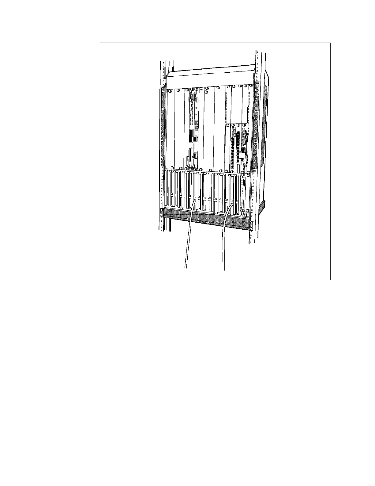
Figure 1. IBM 8260 Model 017
1.2.1.2 Payload Area
The payload area provides the housing for 17 media and management modules.
In addition to the 8260 module, you may install all the 8250 modules (except the
Controller module) in an 8260. Once these modules are installed on the 8260,
they will be connected to the backplane.
Certain modules provide you with
to connect different ports on the same module to different backplane segments.
Other modules are
the module must be connected to the same network segment. The per-port
switching capability is available for both Ethernet and token-ring.
Since the 8260 modules are taller than the 8250 modules, when you install one or
more 8250 modules in the 8260 multiprotocol intelligent switching hub, you must
use the
kit enables you to install up to 4, 9 or 16 single-slot 8250 modules or a mixture of
single-slot and dual-slot 8250 modules.
The 8250 adapter kit consists of the following:
8250 Adapter Kit
4 8260 Multiprotocol Intelligent Switching Hub
per-port switching
module-switching
. Depending on the kit that you order, the 8250 adapter
modules, which means that all the ports on
capability, which allows you
Page 27
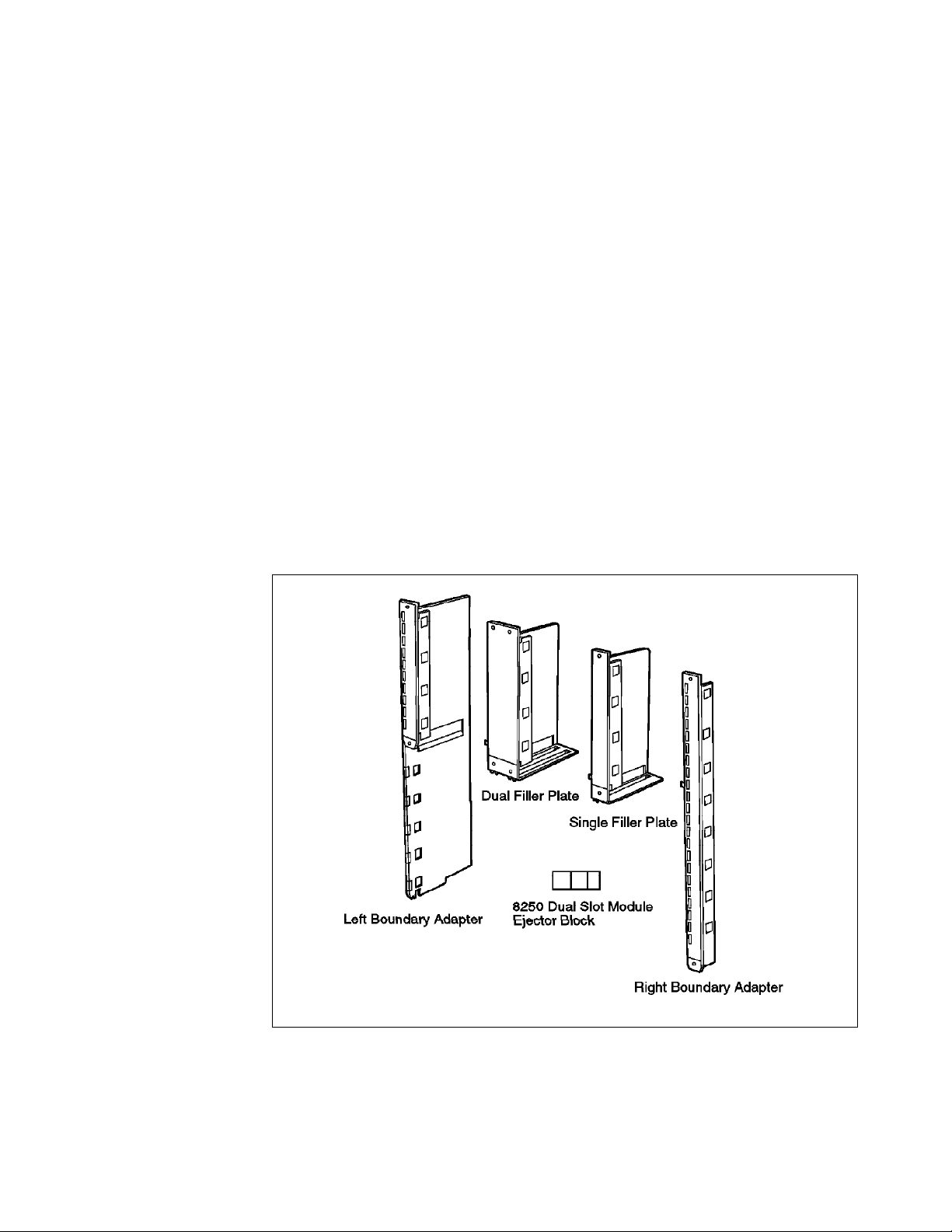
•
Right Boundary Adapter: This adapter is a full length adapter and occupies
one slot. Installation of this adapter results in 16 slots remaining available in
the 8260 for the installation of media and management modules. It is
recommended that you install this adapter in slot 17. The reason for this is
that if an 8250 management module becomes the master management
module, it will always see the Controller module installed in slot 17.
Therefore, if there is any other module installed in this position, it will not be
recognized by the xMM.
Note: If a DMM is the master management module, it will always be able to
recognize the module installed in slot 17.
•
Left Boundary Adapter: This adapter will be installed on the left boundary of
the area occupied by the 8250 modules. The top portion of this adapter
provides a filler plate, while the bottom-portion will provide you with the
room to install an 8250 module.
•
Dual-slot Top Filler: This adapter provides the filler plate for two slots of the
8260 providing you with the room to install two single-slot (or one dual-slot)
8250 module.
•
Single-slot Top Filler: This adapter provides the filler plate for one slot of the
8260 providing you with the room to install a single-slot 8250 module. Note
that two of these adapters can be used to install a dual-slot 8250 module.
The components of the 8250 adapter kit are shown in Figure 2.
Figure 2. Components of the 8250 Adapter Kit
Table 1 on page 6 shows the quantity of each component for the various 8250
adapter kits:
Chapter 1. An Overview of the IBM 8260 Hub 5
Page 28

Table 1. Components of the 8250 Adapter Kit for 8260
Adapter kit Component 4-slot Feature 9-slot Feature 16-slot
Feature
Left Boundary Adapter 1 1 1
Right Boundary Adapter 1 1 1
Dual-Slot Top Filler 1 3 7
Single-Slot Top Filler 1 2 1
Dual-Slot Module Ejector Blocks 4 9 16
8250 Module Blank Faceplate 3 8 15
1.2.1.3 Fault-Tolerant Controller Module Slots
The Controller module provides all the clocking signals for the 8260. It is also
used to provide management of the power subsystem and the cooling
subsystem.
The 8260 chassis has two dedicated slots for the use of the Fault-Tolerant
Controller modules. These are referred to as slots 18 and 19. The 8260 Model
17 arrives with 1 Controller module as standard which is required for the
operation of the 8260. You may install a second Controller module which will be
used to back up the primary Controller module in case of failure. Fault tolerance
is established when there are two Controller modules installed. Either module
may be the master but in the event of the master Controller module failing and
will
the standby Controller module taking over, the network
be disrupted.
1.2.1.4 The Intelligent Power Subsystem
The power subsystem provides an easy access power bay which can support up
to four load-sharing, high capacity, managed power supplies. The 8260 Model
017 arrives with one power supply as standard and you may optionally install
three additional power supplies. Features of the power subsystem are:
•
Accessibility
The power bay is easily accessed from the front of the 8260.
•
Hot pluggability
You may install or remove power supplies while the hub is operating from
the other installed power supplies.
•
High capacity power supplies
Each power supply provides up to 295 watts of power.
•
Load sharing capability
The power consumption is evenly distributed over all the power supplies.
•
Power management
Using a combination of the DMM and the Controller module the power
subsystem can be monitored and controlled in either fault tolerant or
non-fault tolerant mode.
All of these features add up to a true seamless redundancy of the power
subsystem. The intelligent power subsystem is fully described in Chapter 5,
“8260 Intelligent Power Management Subsystem” on page 73.
6 8260 Multiprotocol Intelligent Switching Hub
Page 29

1.2.2 The Intelligent Cooling Subsystem
The cooling subsystem consists of 3 fans, each of which cools a specific area of
the hub. Each of the fans has a sensor to detect a slow or stopped condition and
a temperature sensor to detect an over temperature condition. In conjunction
with the Controller module and the DMM the hub environment can be monitored
and controlled for over temperature conditions. Fan and Temp LEDs on the
Controller module can also alert the user to potential problems. The intelligent
cooling subsystem is described in detail in Chapter 6, “8260 Intelligent Cooling
Subsystem” on page 91.
1.2.2.1 Distributed Management Architecture
To fully manage the 8260 and the installed modules, the 8260 uses a distributed
management architecture. In this architecture, the various tasks of managing
the various elements of the hub are distributed across the following elements:
•
Distributed management module
•
MAC daughter cards
•
Controller module
There are 2 types of distributed management module (DMM):
•
Stand-alone DMM
•
EC-DMM
In terms of management functions, DMM and EC-DMM are identical. The only
difference between these two cards is their ability to house Ethernet MAC
daughter cards.
The DMM, along with the fault-tolerant Controller module, manages and controls
the 8260 hub and its modules. However, to perform certain management
functions such as network traffic monitoring, there is a need for a daughter card
to assist DMM. There are two types of daughter cards:
•
•
The combination of DMM and daughter cards provides a cost efficient
management architecture that consolidates media management into a single
card, while distributing network monitoring across a series of protocol dependent
daughter cards. Detailed information about the distributed management
architecture of the 8260 and the management modules and daughter cards is
provided in Chapter 4, “8260 Distributed Management Architecture” on page 35.
1.2.3 8260 Model 010
The 8260 Model 010 is a 10-slot intelligent hub that shares many of the advanced
features of the 8260 Model 017. I t differs from the Model 017 in the following
areas:
•
•
Ethernet Media Access (E-MAC) daughter card
Token-ring Media Access (T-MAC) daughter card
It offers 10 payload slots, rather than 17.
It allows up to three power supplies, rather than four. The basic 8260 Model
010 is shipped with a single power supply, and up to two additional power
supplies can be added later. The same power supplies are used on both
models.
Chapter 1. An Overview of the IBM 8260 Hub 7
Page 30

•
Model 010 is shorter than the Model 017 (498 mm versus 673 mm), but has
the same depth and width.
•
Power supplies in the Model 010 are housed on the left side of the chassis
whereas in the Model 017 they are housed in the bottom section.
The 8260 Model 010 shares with the Model 017 all of the following benefits:
•
Supports three fan units.
•
Supports two Controller module slots for redundancy. The basic model is
shipped with one Controller module, and a second Controller module can be
added for redundancy.
•
It uses the same chassis accessories and chassis features:
− Rack mount kit
− Cable management tray
− Power supplies
− Fan units
− Controller module
•
Like the 8260 Model 017, the 8260 Model 010 is field upgradeable to support
ATM.
By sharing same chassis elements, networks can be built using a mixture of
Model 017s and Model 010s without an overhead for managing accessories and
spare parts.
Note
In the remainder of this book, the various components of the IBM 8260 are
explained assuming an 8260 Model 017.
1.3 8260 Modules and Daughter Cards
This section will give an overview of currently available 8260 modules and
daughter cards and a brief description of them. Details of individual modules,
the necessary steps required to configure them, and some testing scenarios will
be described in the following chapters. Currently, the available 8260 modules
and daughter cards can be classified as follows:
1.3.1 Ethernet Modules
1.3.1.1 8260 Ethernet 24-Port 10Base-T Module
The 8260 Ethernet 24-port 10Base-T module is single-slot module which provides
two Telco connectors for supporting 24 Ethernet ports. This module provides
per-port switching capability which enables you to connect each port to any of
the eight Ethernet segments on the backplane.
8 8260 Multiprotocol Intelligent Switching Hub
Page 31

1.3.1.2 8260 Ethernet 20-Port 10Base-T Module
The 8260 Ethernet 20-port 10Base-T module is single-slot module which provides
20 RJ-45 connectors for supporting 20 Ethernet ports. This module provides
per-port switching capability.
1.3.1.3 8260 Ethernet 40-Port 10Base-T Module
The 8260 Ethernet 40-port 10Base-T module is two-slot module which provides 40
RJ-45 connectors for supporting 40 Ethernet ports. This module provides
per-port switching capability.
1.3.1.4 8260 Ethernet 10-Base-FB Module
The 8260 Ethernet 10-Base-FB module is a single-slot module that provides 10
fiber ports which can be used to provide fiber backbone for Ethernet segments
using IEEE 10Base-F standard. You can also use these ports for connecting to
Ethernet ports using optical fiber cables. This module provides per-port
switching capability and can be ordered with one of the following connector
types:
•
ST
•
FC
•
SMA
1.3.1.5 8260 Multiprotocol Interconnect Module
The 8260 Multiprotocol Interconnect module is a one or two-slot module which
allows you to interconnect Ethernet, 802.3 and token-ring networks using bridging
and/or routing functions. Both models provide up to 6 logical ports for
attachment to Ethernet segments on the backplane, and the two-slot module
provides the capability to install two I/O cards which allow you to connect it to
external token-ring and Ethernet networks.
1.3.1.6 Ethernet Security Card
This is a daughter card that can be installed on any 8260 Ethernet media module
and provides you with the ability to perform intrusion protection and/or
eavesdropping protection for an Ethernet segment.
1.3.2 Token-Ring Modules
1.3.2.1 8260 TR 18 Port Active PPS Switch Module
The 8260 TR 18 Port Active PPS (Per-Port Switching) module is a single-slot
module which provides you with 18 RJ-45 connectors for attaching up to 18
workstations to the token-ring segments on the ShuntBus using both STP and
UTP cables. Using the per-port switching capability, any of the ports on this
module can be connected to any of the 10 token-ring segments on the ShuntBus
or 11 isolated segments on the module.
This module provides active re-timing and regeneration of the signal on every
port allowing you to have longer lobe distances for both STP and UTP cabling.
Ports 17 and 18 on this module can optionally be configured to act as fully
repeated RI/RO trunk ports.
Chapter 1. An Overview of the IBM 8260 Hub 9
Page 32

1.3.2.2 8260 TR 18 Port Active Module Switching Module
The 8260 TR 18 Port Active Module Switching module is a single-slot module
which provides attachment of up to 18 workstations to one of the 10 token-ring
segments on the ShuntBus using both STP and UTP cables. This module
provides active re-timing and regeneration of the signal on every port.
Ports 17 and 18 on this module can optionally be configured to act as fully
repeated RI/RO trunk ports.
1.3.2.3 8260 TR Dual Fiber Repeater Module
The 8260 TR Dual Fiber Repeater module is a single-slot module providing 10
lobe ports with RJ-45 connectors and two RI/RO trunk ports with ST fiber
connectors. Using the per-port switching feature, any of the lobes or any set of
RI/RO trunk ports can be connected to any of the 10 token-ring segments on the
ShuntBus.
Lobe ports support both UTP and STP cabling and each port provides active
re-timing and regeneration of the signal.
The fiber RI/RO trunk ports are fully repeated and can be used for connecting
your 8260 to other hubs over a distance of 2 km.
1.3.2.4 8260 TR 20 Port Passive Module-Switching Module
The 8260 TR 20 Port Passive Module-Switching module is a single-slot module
which allows you to attach up to 20 workstations, which can be switched on a
per module basis, to any of the 10 token ring networks on the backplane. This
module allows you to use either UTP or STP cabling. Unlike the active module,
it does not provide simultaneous support for both UTP and STP cabling.
1.3.2.5 8260 Jitter Attenuator Daughter Card
The 8260 Jitter Attenuator daughter card allows you to filter excessive amounts
of jitter that may have accumulated in other equipment, before passing the
signal to the 8260 backplane. The Jitter Attenuator daughter card can be
mounted on any 8260 token-ring media module.
1.3.3 Management and Controller Modules
1.3.3.1 8260 Distributed Management Module (DMM)
The Distributed Management Module is an independent management module
which allows you to fully manage and control the 8260 Multiprotocol Intelligent
Hub and all the 8250/8260 modules. The DMM provides you with flexibility in
handling the management of network segments with different protocols and
media modules via a single management module using a single slot in the 8260
payload area. There are two different versions of DMM:
•
A Distributed Management Module with Ethernet Carrier - (DMM with Ethernet
Carrier) - The DMM with Ethernet Carrier module is a management module
which is capable of housing up to 6 Ethernet MAC daughter cards.
•
A Stand-alone Distributed Management Module (Stand-alone DMM ) - the
stand-alone DDM module is a management module which is not capable of
housing any Ethernet MAC daughter cards.
10 8260 Multiprotocol Intelligent Switching Hub
Page 33

1.3.3.2 8260 Fault-Tolerant Controller module
The 8260 Fault-Tolerant Controller Module synchronizes the operations of all
installed media and management modules by providing clocking and timing to
the 8260 Multiprotocol Intelligent Hub Backplane. The Controller module is also
responsible for managing the power and cooling subsystems.
1.3.3.3 Ethernet Media Access Daughter Card (E-MAC)
The E-MAC daughter card allows you to gather statistics for the network to which
it is attached. It can be physically mounted to either an 8260 Ethernet media
module or the 8260 EC-DMM.
1.3.3.4 8260 Token-Ring Media Access Daughter Card (T-MAC)
The T-MAC daughter card allows you to gather statistics for the network to which
it is assigned. It can be mounted on any 8260 token-ring media module.
Chapter 1. An Overview of the IBM 8260 Hub 11
Page 34

12 8260 Multiprotocol Intelligent Switching Hub
Page 35

Chapter 2. Backplane Architecture
The 8260 backplane consists of the following two buses:
•
Enhanced TriChannel
•
ShuntBus
These two buses are standard features of all the 8260 models and are installed
on every 8260 shipped to the customers.
The following sections provide detailed information about the 8260 backplane
and how the backplane buses operate.
2.1 LAN Segments on the Backplane
On each backplane bus (both Enhanced TriChannel and ShuntBus) there are 96
pins
which are used for passing the network traffic between the media modules
installed in the hub as well as the control signals between the media modules,
fault-tolerant Controller module, and Distributed Management Module (DMM).
The control signals are used to carry clocking, voltage, status and other
information pertinent to the proper operation of the hub and the installed
modules.
On the Enhanced TriChannel, 54 pins are available to be used for passing
network traffic. the rest of the pins are used for non-data traffic signals. These
signals are used for passing control signals between the Controller module and
the media modules as well as signals between the Management module and the
media modules. More information about these non-data traffic signals are
provided in 2.5.1, “Management Buses” on page 26.
On the Enhanced TriChannel, the pins used for passing the network traffic are
not permanently allocated to a specific type of network. Instead a pin may be
configured to be used for passing either token-ring, Ethernet or FDDI packets at
any one time. This enables more efficient utilization of the backplane resources.
The following is the maximum number of permitted LAN segments when a single
protocol is used on the Enhanced TriChannel:
•
6 Ethernet segments or
•
7 token-ring segments or
•
4 FDDI segments
Note that you are allowed to have a mixture of token-ring, Ethernet and FDDI
segments on the Enhanced TriChannel. In this case, the exact number of each
network type which is allowed in a mixed protocol environment depends on the
configuration of your hub. For detailed information about the permitted
configurations in a mixed protocol environment please refer to 2.5, “Network
Allocations on the 8260 Backplane” on page 23.
Figure 3 on page 14 provides an overview of the Enhanced TriChannel bus.
Copyright IBM Corp. 1995 13
Page 36
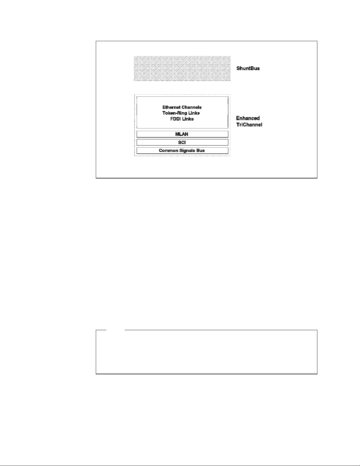
Figure 3. Enhanced TriChannel Bus
The number of pins available for user traffic on the ShuntBus is 72 pins. These
pins are used to set up 2 dedicated Ethernet segments as well as 10 token-ring
(or 4 FDDI) segments as shown in Figure 4 on page 15.
On the ShuntBus, 8 pins out of the 72 network traffic pins are dedicated to be
used by two Ethernet segments. These dedicated pins are not available to be
used by other segment types. The remaining 64 pins on the ShuntBus are
available to be used by token-ring and/or FDDI segments. This allows you to
have a mixture of token-ring and FDDI segments as well as two Ethernet
segments on the ShuntBus. The rules governing the maximum number of FDDI
and token-ring segments allowed in a mixed token-ring and FDDI environment
are discussed in 2.5, “Network Allocations on the 8260 Backplane” on page 23.
The following is the permitted maximum number of LAN segments on the
ShuntBus:
•
2 Ethernet and
•
10 token-ring or 4 FDDI
Note
At the time of writing this publication, there are no FDDI modules available
that can be assigned to the FDDI segments on the ShuntBus. Therefore,
practically, the ShuntBus allows you to have two Ethernet segments plus 10
token-ring segments.
14 8260 Multiprotocol Intelligent Switching Hub
Page 37

Figure 4. 8260 ShuntBus
2.2 Ethernet Segments on the Backplane
The 8260 allows you to set up a maximum of 6 Ethernet (ethernet_1 thru 6)
segments on the Enhanced TriChannel and two Ethernet segments (ethernet_7
and 8) on the ShuntBus. ethernet_1 thru 3 can consist of 8250 and/or 8260
Ethernet modules, whereas ethernet_4 thru 8 can consist of 8260 Ethernet
modules only.
Each Ethernet segment on the backplane uses a number of pins on the
backplane which is referred to as an
8 Ethernet paths (ethernet_path_1 thru 8) on and 8260. ethernet_path_1 thru 6
are on the Enhanced TriChannel whereas ethernet_path_7 and 8 are on the
ShuntBus.
Ethernet_path_1 thru 3 use 14 pins each to set up an Ethernet segment while
ethernet_path_4 thru 8 use 4 pins each.
The Ethernet segments on the Enhanced TriChannel use the same pins on the
backplane as are used by the token-ring and/or FDDI segments. Therefore,
simultaneous configuration of other types of networks (such as FDDI and/or
token-ring) on your hub′s Enhanced TriChannel will impact the number of
Ethernet networks available for use. However, the two Ethernet segments on the
ShuntBus have dedicated pins on the backplane and will not be impacted by the
configuration of other segment types (that is, token-ring and/or FDDI) on the
ShuntBus.
Ethernet Path
in this document. There are
Each Ethernet segment on the 8260 utilizes one of the Ethernet paths on the
backplane regardless of the number of Ethernet modules which constitute that
segment. You can choose the Ethernet network (hence the Ethernet path used
by your module) using the following management command:
Chapter 2. Backplane Architecture 15
Page 38

SET MODULE {slot.sublsot} NETWORK {ethernet_n} or
SET PORT {slot.port} NETWORK {ethernet_n}
Before assigning the port or module to a network you may use the following
management command to display the availability of the Ethernet segments on
the Enhanced TriChannel and the ShuntBus:
SHOW BACKPLANE_PATHS ETHERNET
An example of the output from this command is shown in Figure 5.
8260> show backplane_paths ethernet
Physical Path Logical Network
--------------- --------------ETHERNET_PATH_1 ETHERNET_1
ETHERNET_PATH_2 in use
ETHERNET_PATH_3 in use
ETHERNET_PATH_4 available
ETHERNET_PATH_5 ETHERNET_5
ETHERNET_PATH_6 ETHERNET_6
ETHERNET_PATH_7 ETHERNET_7
ETHERNET_PATH_8 ETHERNET_8
8260>
Figure 5. Backplane Path Display for Ethernet Segments
In this example, the Ethernet segments shown ″in use″ are not available to be
used for setting up Ethernet segments in this hub due to the backplane pins
corresponding to these segments being currently used by other segment types
such as token-ring and/or FDDI. Ethernet_1 and ethernet_5 through ethernet_8
are currently configured to be used by Ethernet modules in this hub. The pins
available to be used by ethernet_4 are not currently configured to be used by
any network type.
To connect and use the Ethernet segments on the backplane (Enhanced
TriChannel or ShuntBus) various techniques are used by the various 8250 and
8260 Ethernet modules. These techniques can be categorized into one of the
three following methods:
•
Method 1:
This method uses 14 pins on the backplane to set up an Ethernet segment.
In this method, each module attached to the Ethernet segment will send the
slot-id and port-id of the transmitting station in
The slot-id will use 5 pins and the port-id will use 4 pins on the backplane as
shown in Table 2 on page 17.
The slot-id will be used to perform
2.2.1, “Digital Collision Detection” on page 19. Additionally, the slot-id and
the port-id will be used by the management module to perform statistics
gathering about the segment as well as the individual ports and modules on
that segment as described in 2.2.3, “Statistics Collection” on page 19.
digital collision detection
parallel
over the backplane.
as described in
This method is used by all 8250 modules and is only allowed on ethernet_1,
ethernet_2, and ethernet_3 segments on the Enhanced TriChannel.
Therefore, the 8250 Ethernet modules installed in the 8260 can only be
assigned to these three segments and can not be assigned to Ethernet
16 8260 Multiprotocol Intelligent Switching Hub
Page 39

segments ethernet_4, ethernet_5 and ethernet_6 on the Enhanced TriChannel
and ethernet_7 and ethernet_8 on the ShuntBus.
•
Method 2:
This method also uses 14 pins on the backplane to set up an Ethernet
segment. In this method, each module attached to that Ethernet segment
will use digital collision detection identical to that used in method 1. This
means that the modules will send their slot-id in parallel over the backplane.
However, to allow the management module to collect statistics about these
modules, they send the slot-id and port-id in serial over a single pin on the
backplane.
This method is used by the 8260 modules when connected to ethernet_1,
ethernet_2, and ethernet_3 segments on the Enhanced TriChannel.
Method 2 is compatible with method 1. That is, modules using method 1 and
2 can be assigned to the same Ethernet LAN segment. Therefore, you may
set up ethernet_1, thru ethernet_3 to consist of a mixture of the 8250 and/or
8260 Ethernet modules.
•
Method 3:
This method uses only four pins on the backplane to set up an Ethernet
segment. In this method, each module will send its slot-id and port-id in
serial over a single pin on the backplane. This information allows the
management module to collect statistics about the modules and ports.
For collision detection, the modules using this method rely on an
collision detection
as described in 2.2.2, “Analog Collision Detection” on
analog
page 19.
This method is used by the 8260 modules when connected to ethernet_4,
ethernet_5, and ethernet_6 segments on the Enhanced TriChannel as well as
ethernet_7 and ethernet_8 segments on the ShuntBus.
This method is not compatible with methods 1 and 2. Therefore, ethernet_4
thru ethernet_8 segments can consist of 8260 Ethernet modules only.
Table 2 gives a breakdown of the pins which are used by 8250 and 8260 Ethernet
modules when using the above methods.
Table 2 (Page 1 of 2). Ethernet Pins on the 8260 Backplane
Description Method 1 Method 2 Method 3
Data enable signal Y Y Y
Data in NRZ format Y Y Y
Local collision Y Y N/A
Remote collision Y N N/A
Analog collision N/A N/A Y
Port ID bit 0 (lsb) Y N N/A
Port ID bit 1 Y N N/A
Port ID bit 2 Y N N/A
Port ID bit 3 (msb) Y N N/A
Slot ID bit 0 (lsb) Y Y N/A
Slot ID bit 1 Y Y N/A
Slot ID bit 2 Y Y N/A
Chapter 2. Backplane Architecture 17
Page 40

Table 2 (Page 2 of 2). Ethernet Pins on the 8260 Backplane
Description Method 1 Method 2 Method 3
Slot ID bit 3 Y Y N/A
Slot ID bit 4 (msb) Y Y N/A
Serial ID N Y Y
The following is a brief description of the use of each of the pins in an Ethernet
segment on the 8260 backplanes:
•
Data enable signal
:
When this signal is active, data on the backplane is valid and the modules
should receive and process the data on the ′Data in NRZ Format′ pin.
•
Data in NRZ format
:
This signal is used to transmit data on the backplane in NRZ format.
•
Local collision
:
This signal is used to indicate local collisions on the backplane. It is raised
when two or more modules on the same segment are transmitting data at
the same time. It is also raised if two or more ports on the same module
transmit simultaneously.
•
Remote Collision
:
This signal is raised when a collision occurs in a remote hub. This signal is
only used by the 10Base-FB modules.
•
Port-ID:
Whenever an Ethernet module using method 1 transmits data on the
backplane, it must sent the port-id of the transmitting port on these pins.
The Management module will use the port-id and slot-id (see below) signals
to find out which port and module is sending the data on the ′Data in NRZ
Format′ pin; hence, it is able to collect and report per-port statistics.
Note: Since four pins are used to transmit the port ID in parallel, the
per-port statistics cannot be reported for all the ports of the 24-port modules.
On a 24-port module, you can collect statistics about the first 12 ports only.
•
Slot ID
:
Whenever an Ethernet module is using method 1 or 2 to transmit data on the
backplane, it must send its slot-id on these five pins. This information is
used for two purposes:
1. Digital collision detection
2. Statistics collection
•
Serial-ID
:
This pin is used to transmit the port-id and slot-id, over the backplane, in
serial format. Its purpose is to provide the Management module with a way
to collect per-port and per-module statistics for modules using method 2 and
3.
•
Analog Collision
:
18 8260 Multiprotocol Intelligent Switching Hub
Page 41

This pin is used to provide a means of detecting collisions of the segments
using method 3. Analog collision detection is described in 2.2.2, “Analog
Collision Detection” on page 19.
2.2.1 Digital Collision Detection
Collision detection on the backplane (for methods 1 and 2) is done by using
slot-id information transmitted on the backplane. Each module asserts its own
slot-id one bit time before transmitting user data on the data pin. The following
bit time, the module reads the slot-id received on these pins and compares it
with its own slot-id. If only one module is transmitting, the transmitted and
received slot-id values are the same and no collision exists. If more than one
module is transmitting, then at least one module will detect an unequal slot-id
comparison and will then signal local collision.
It should be noted that slot-id mismatches will not always occur in all modules
involved in a collision. This is because, the slot-id sent on the bus is the ′OR′ of
the two or more slot-ids transmitted by the individual modules. For example, if
the module in slot 8 (B′0111′) collides with the module in slot 1 (B′0000′), the
backplane will ″OR″ the two together and both modules will see B′0111′. This
will look all right to the module in slot 8, so it will not assert the local collision
pin. However, the module in slot 1 will detect the slot-id mismatch and will
assert the local collision pin.
2.2.2 Analog Collision Detection
To perform analog collision detection, a current source is used to generate a
level on the backplane. Each time a module starts transmitting, the voltage on
the backplane drops. If more than one module is transmitting at the same time,
the drop at the voltage level is used to detect such a condition.
2.2.3 Statistics Collection
The slot-id in conjunction with the port-id and the user data is used by the
Management module to collect statistical information about the ethernet_1,
ethernet_2 or ethernet_3 segment as well as the individual ports and modules on
that segment. For method 1 the slot-id and port-id are sent by the module in
parallel over 9 pins on the backplane, whereas, modules employing methods 2
and 3 use a single pin on the backplane to transmit their slot-id and port-id.
2.3 Token-Ring Segments on the Backplane
The 8260 allows you to set up a maximum of 7 token-ring segments on the
Enhanced TriChannel using the 8250 modules. Also, you can set up 10
token-ring segments on the ShuntBus using the 8260 token-ring modules. Note
that the 8250 token-ring modules only connect to the Enhanced TriChannel and
the 8260 modules only connect to the ShuntBus; therefore, if you want to set up a
token-ring segment consisting of these two different types of modules, you must
connect the segments together using RI/RO connections, bridges, or routers.
Each 8250 token-ring module which is assigned to one of the 7 token-ring
networks on the Enhanced TriChannel uses one of the resources called a
token-ring path
they are referred to as tr_path_8250_1 through tr_path_8250_15. Each token-ring
path utilizes 4 pins on the Enhanced TriChannel. These pins are as follows:
. There are 15 token-ring paths on the Enhanced TriChannel and
Chapter 2. Backplane Architecture 19
Page 42

•
Data-in
•
Clock-in
•
Data-out
•
Clock-out
When you assign an 8250 token-ring module to one of the token-ring networks on
the Enhanced TriChannel (tr_8250_1 through tr_8250_7) using the following
command:
SET MODULE {slot.sublsot} NETWORK {token_ring_n}
The 8260 will automatically allocate one of the available token-ring paths to this
module. Note that you can neither choose the path used by the module, nor
determine which path is used by a specific module. However, you can
determine all token-ring paths on the Enhanced TriChannel which are currently
being allocated in your hub by using the following management module
command:
SHOW BACKPLANE_PATHS TOKEN_RING
An example of the output from this command is shown in Figure 6.
8260> show backplane_paths token_ring
Physical Path Logical Network
--------------- --------------TR_PATH_8250_1 in use
TR_PATH_8250_2 in use
TR_PATH_8250_3 in use
TR_PATH_8250_4 in use
TR_PATH_8250_5 in use
TR_PATH_8250_6 in use
TR_PATH_8250_7 TR_8250_1
TR_PATH_8250_8 available
TR_PATH_8250_9 TR_8250_1
TR_PATH_8250_10 available
TR_PATH_8250_11 in use
TR_PATH_8250_12 in use
TR_PATH_8250_13 TR_8250_1
TR_PATH_8250_14 available
TR_PATH_8250_15 available
8260>
Figure 6. Token-Ring Backplane Path Display
The number of token-ring paths used by a single token-ring network on the
Enhanced TriChannel equals the number of token-ring modules on that network.
Note that the token-ring paths on the Enhanced TriChannel use the same pins on
the backplane as are used by the Ethernet and/or FDDI segments. Therefore,
simultaneous configuration of other types of networks in your hub will impact the
number of token-ring networks allowed in your hub. In Figure 6, the token-ring
paths shown as in ″in use″ are those backplane pins that are used by other
segment types (that is, Ethernet or FDDI), whereas tr_path_8250_7,
tr_path_8250_9 and tr_path_8250_13 are used to configure a single token-ring
segment (tr_8250_1) consisting of three 8250 token-ring modules. Also, note that
20 8260 Multiprotocol Intelligent Switching Hub
Page 43
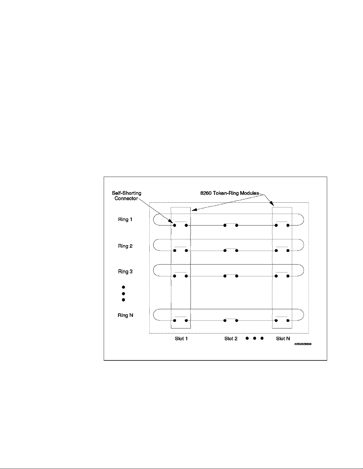
the token-ring paths marked as ″available″ are the parts of the Enhanced
TriChannel that are not currently used by any type of network.
On the ShuntBus, in addition to the two dedicated Ethernet segments, there are
10 token-ring segments. Unlike, the Enhanced TriChannel, there is no concept of
token-ring paths on the ShuntBus. Instead, there are 10 physical rings on the
backplane. Each of these rings is a set of 6 pins which is routed from slot to slot
on the backplane and is completed across each slot via a self-shorting
connector. At the end of the backplane, the signal path is returned from slot 17
to slot 1. I n this manner, a ring is formed. When a module is inserted into the
backplane, the self-shorting connector opens and the signal is routed onto the
module. Therefore, any installed token-ring module on the ShuntBus has access
to any of the 10 token-ring segments on the backplane. This design allows the
implementation of per-port switching for the token-ring modules so that
individual ports on a module can be assigned to different rings on the backplane.
This concept is shown in Figure 7. Details of the per-port switching feature for
token-ring modules is provided in Chapter 8, “8260 Token-Ring Support” on
page 129.
Figure 7. ShuntBus and Token-Ring
Each token-ring interface on the ShuntBus connector uses three Shunt pairs (low
resistance connectors) to form one token-ring network on the backplane. The
three Shunt pairs carry a clock and two data signals.
When a token-ring module is inserted into the ring, the 3 Shunt pairs connect to
6 signal lines on the module as:
•
Clock transmit
•
Data A transmit
Chapter 2. Backplane Architecture 21
Page 44

•
Data B transmit
•
Clock receive
•
Data A receive
•
Data B receive
The reasons for two signals for each of the transmit and receive signals is given
in 8.2, “8260 Backplane Signalling for TR Segments” on page 134.
Note that regardless of the number of token-ring modules used in a segment,
you always have the ability to set up 10 separate token-ring segments on the
ShuntBus.
The same pins that are used for token-ring segments on the ShuntBus are
designed to be used for FDDI segments as well. Therefore, if you have a mixture
of token-ring and FDDI segments on the ShuntBus, the maximum number of
token-ring segments would be lower, depending on the number of FDDI
segments. However, this is a theoretical limitation for the time being, as
currently IBM is not offering any 8260 FDDI modules.
2.4 FDDI Segments on the Backplane
The 8260 allows you to set up a maximum of 4 FDDI segments on the Enhanced
TriChannel using the 8250 modules. Also, it is possible to set up a maximum of
4 FDDI segments on the ShuntBus, using the 8260 FDDI modules. However, as
there are no 8260 FDDI modules available yet, if you are planning to have FDDI
segments on the 8260, you must use the 8250 FDDI modules to set up FDDI
segments on the Enhanced TriChannel only.
Each FDDI module which is assigned to one of the four FDDI networks on the
Enhanced TriChannel uses one of the resources called
FDDI path
. There are 8
FDDI paths on the Enhanced TriChannel and are referred to as fddi_path_8250_1
through fddi_path_8250_8. Each FDDI path utilizes 6 pins of the Enhanced
TriChannel. These pins are as follows:
•
Data-in
•
Symbol parity-in
•
Clock-in
•
Data-out
•
Symbol parity-put
•
Clock-out
When you assign an FDDI module to one of the four FDDI networks on the
Enhanced TriChannel (fddi_1 through fddi_4), using the following command:
SET MODULE {slot.sublsot} NETWORK {FDDI_n}
the 8260 will automatically allocate one of the available FDDI paths to this
module. Note that you can neither choose the path used by a module, nor
determine which path is used by a specific module. However, you can
determine all the FDDI paths on the Enhanced TriChannel which are currently
being used in your hub by using the following management module command:
SHOW BACKPLNE_PATHS FDDI
22 8260 Multiprotocol Intelligent Switching Hub
Page 45

An example of the output from this command is shown in Figure 8 on page 23.
8260> show backplane_paths fddi
Physical Path Logical Network
--------------- --------------FDDI_PATH_8250_1 in use
FDDI_PATH_8250_2 in use
FDDI_PATH_8250_3 in use
FDDI_PATH_8250_4 in use
FDDI_PATH_8250_5 in use
FDDI_PATH_8250_6 in use
FDDI_PATH_8250_7 in use
FDDI_PATH_8250_8 available
8260>
Figure 8. Backplane Path Display for FDDI Segments
The number of FDDI paths used by a single FDDI network on the Enhanced
TriChannel equals the number of FDDI modules on that network.
The FDDI paths on the Enhanced TriChannel use the same pins on the backplane
as are used by the Ethernet and/or token-ring segments. In Figure 8, the FDDI
paths shown as ″in use″ are those backplane pins which are used by other
segment types (that is, token-ring and/or Ethernet). Also, note that in this
example, we had no FDDI modules installed in our 8260.
On the ShuntBus, in addition to the two dedicated Ethernet segments, there can
be up to 4 FDDI segments. Unlike, the Enhanced TriChannel, there is no concept
of FDDI paths on the ShuntBus. Instead, there are 4 FDDI networks, each using
14 pins. T he FDDI segments on the ShuntBus use the same pins as the
token-ring segments.
2.5 Network Allocations on the 8260 Backplane
As we now have so many options of switching modules and ports between
networks it is perhaps a good time to clarify the rules regarding those
allocations.
•
8250 Ethernet ports or modules can be connected to parallel addressed
segments (ethernet_1 thru 3 on the Enhanced TriChannel) only.
•
8250 Ethernet ports or modules cannot be connected to serially addressed
segments (ethernet_4 thru 8) on either the TriChannel or ShuntBus.
•
8260 Ethernet ports or modules can be connected to any of the segments
(ethernet_1 thru 8) on the TriChannel or ShuntBus. When connected to
ethernet_1 thru 3, they use parallel addressing and when connected to
ethernet_4 thru 8 they use serial addressing.
•
8250 token-ring or FDDI modules can only be connected to the segments on
the Enhanced TriChannel. They cannot be connected to the segments on the
ShuntBus.
•
8260 token-ring (or future 8260 FDDI) modules cannot be connected to any
segment on the Enhanced TriChannel. They can only be connected to the
segments on the ShuntBus.
Chapter 2. Backplane Architecture 23
Page 46
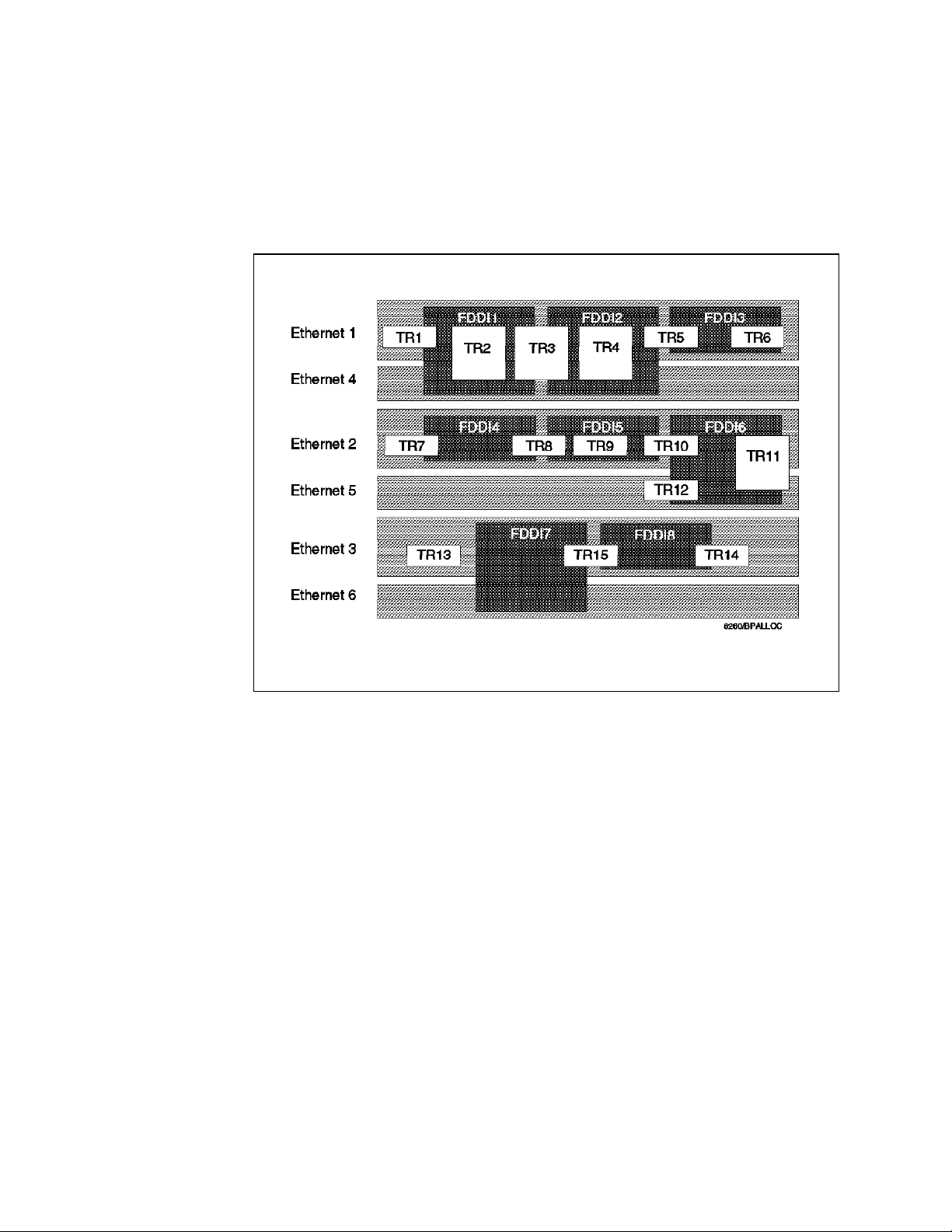
•
Any module can plug into any slot and all allocation of modules to networks
or channels, regardless of whether they are TriChannel or Shunt Bus, is
done by electronic switching (via DIP switches on the modules or
management module commands).
Figure 9 shows the Enhanced TriChannel network allocation and how the mixing
of various network types affect the availability of the others.
Figure 9. TriChannel Backplane Network Allocation
Using Figure 9 you can see that if, for example, tr_path_8250_3 path is used it
eliminates ethernet_path_1, ethernet_path_4, fddi_path_8250_1 and
fddi_path_8250_2. I f ethernet_path_5 is used it eliminates tr_path_8250_11,
tr_path_8250_2 and fddi_path_8250_6.
Figure 10 on page 25 illustrates the possible combinations of the network
segments on the ShuntBus. In this diagram, we have shown the token-ring
networks as TR 16 thru 25 and FDDI networks as FDDI9 thru 12. This is to
provide a distinction between the segments on the Enhanced TriChannel and the
ShuntBus for our discussion in this book. However, when you use the
management module commands to assign the token-ring modules to the
token-ring segments on the backplane, you will refer to the Enhanced TriChannel
segments as token_ring_1 thru 7 and to the ShuntBus segments as token_ring_1
thru 10. I n other words, some token-ring segments on the Enhanced TriChannel
have identical names to the token-ring segments on the ShuntBus. However, the
management module is programmed to realize that when you refer to a
token_ring segment number when issuing a command for the 8250 module, that
segment is on the Enhanced TriChannel and when the command is issued for an
8260 module, the referenced segment number is on the ShuntBus. This is, of
course, due to the fact that 8250 token-ring modules can only be connected to
the Enhanced TriChannel, and the 8260 token-ring modules can only be
connected to the ShuntBus.
24 8260 Multiprotocol Intelligent Switching Hub
Page 47
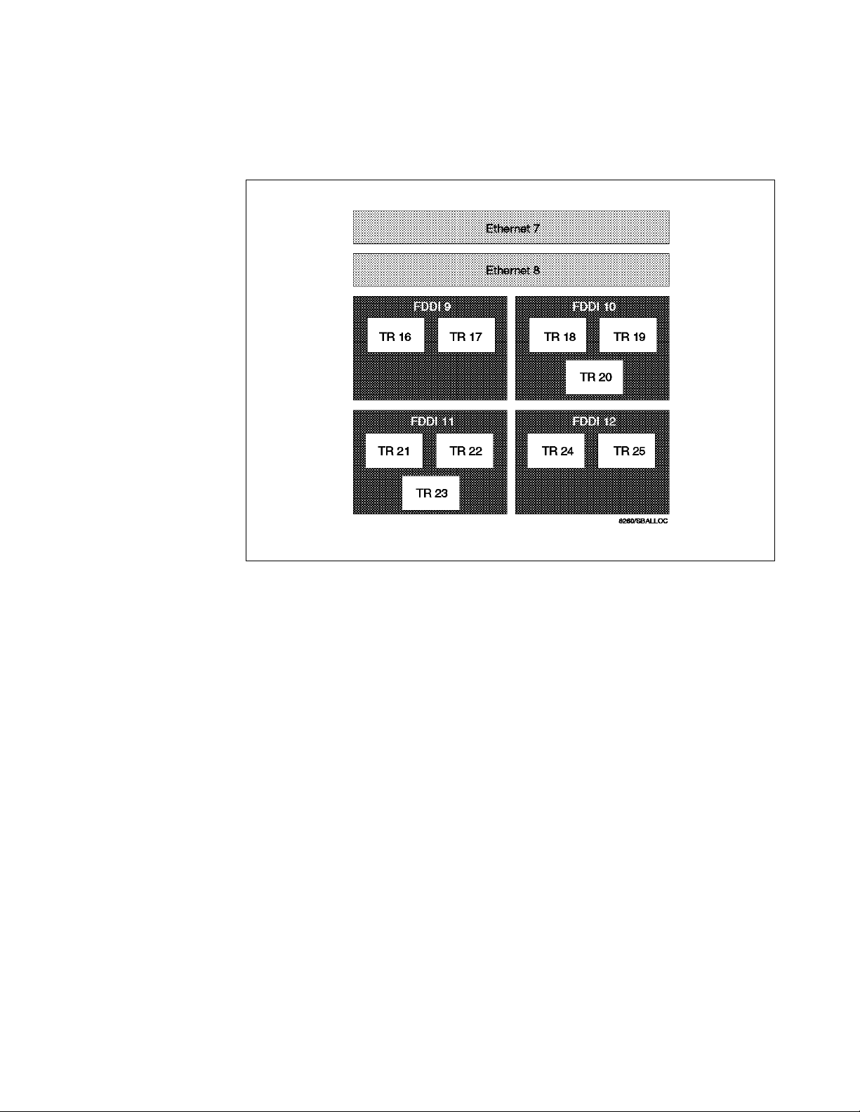
Using Figure 10 on page 25 you can see that if, for example, fddi_1 network on
the ShuntBus is used, it eliminates token_ring_1, token_ring_2 and token_ring_3.
Also, you can see that the use of Ethernet segments ethernet_7 and ethernet_8
have no affect on the availability of token-ring and FDDI segments.
Figure 10. ShuntBus Backplane Network Allocation
Figure 11 on page 26 is a summary of how the Enhanced TriChannel and the
ShuntBus are used to accommodate the various types of networks. Note that in
this diagram, for the sake of avoiding a crowded picture, the token-ring and FDDI
segments on the Enhanced TriChannel are not shown.
In designing your network, if possible, it is recommended that you use the
Enhanced TriChannel as well as the two dedicated Ethernet segments on the
ShuntBus for the Ethernet segments only and use the ShuntBus for the
token-ring segments only.
Chapter 2. Backplane Architecture 25
Page 48

Figure 11. The Backplane Relationship between TriChannel and ShuntBus
2.5.1 Management Buses
It was mentioned earlier that 42 of the 96 pins on the TriChannel Backplane are
reserved for non-data traffic. Included in these pins are the Management LAN
(MLAN) and the Serial Control Interface (SCI).
2.5.1.1 The Management LAN (MLAN)
The MLAN is a dedicated 10 Mbps Ethernet bus which connects the DMM
(Distributed Management Module) and all the Media Access Control daughter
cards (E-MAC or T-MAC). The MAC daughter cards connect to their respective
networks, T-MAC to token-ring and E-MAC to Ethernet, and provide statistics
about those networks to the DMM via the MLAN. Also, the IP stack provided by
26 8260 Multiprotocol Intelligent Switching Hub
Page 49
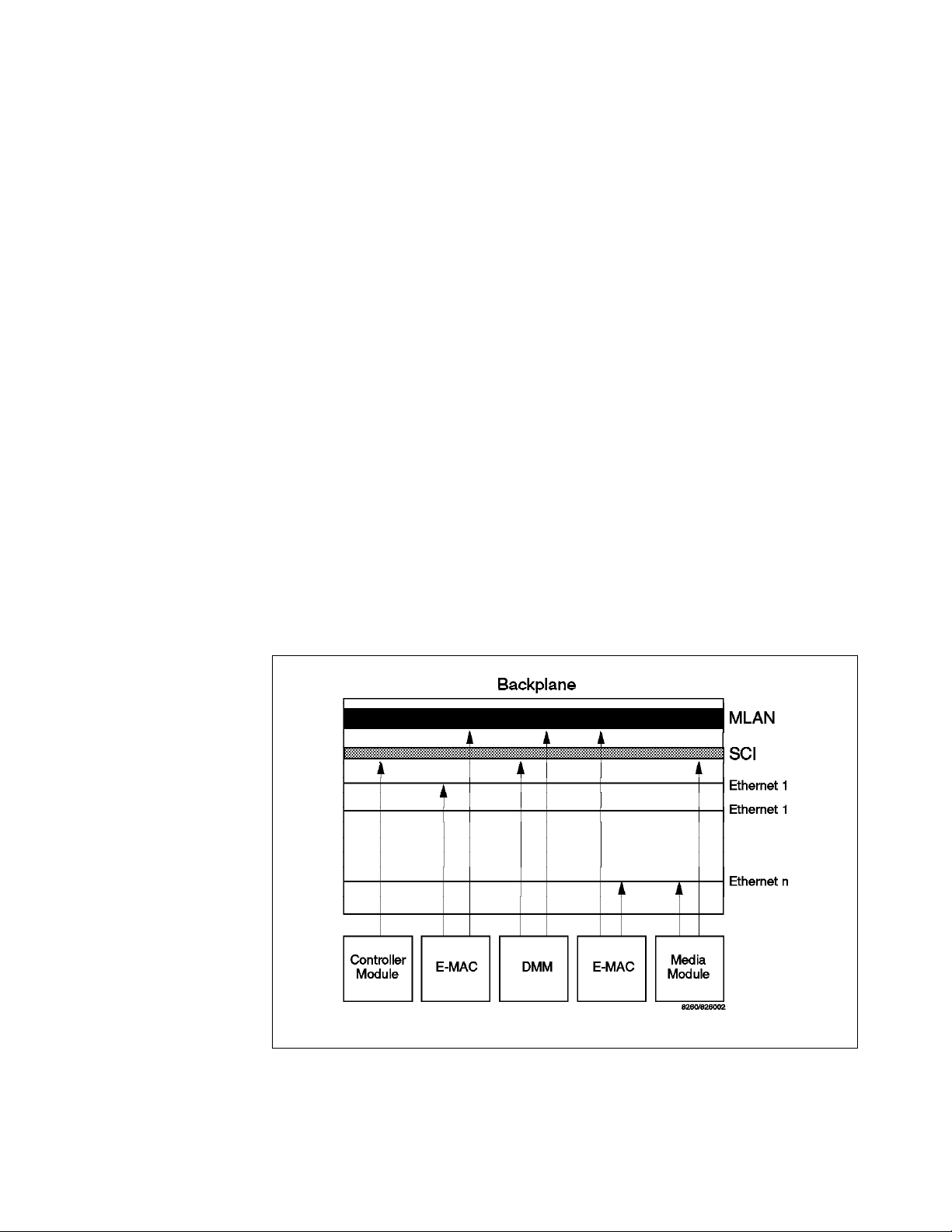
the MAC daughter card is accessed by the upper layer protocol stacks within the
DMM (SNMP, Telnet) through the MLAN.
The E-MAC can be installed on either the EC-DMM or the 8260 media modules.
When installed on the 8260 media modules, E-MAC can collect statistics about all
the Ethernet segments on the backplane, but will not be able to collect per-port
or per-module statistics for the 8250 modules which are on Ethernet_1, 2 and 3.
This is due to the fact that the 8250 modules will be using parallel addressing on
the backplane while the EMAC installed on the 8260 media modules will only be
able to collect statistics from the serial pins. However, if the E-MAC is installed
on the EC-DMM, it will be able to collect a full range of statistical information
about any segment that it is attached to, regardless of whether that segment is
using parallel or serial addressing. This is because the EC-DMM provides
parallel to serial address translation.
Also note that E-MAC is always able to collect full statistics about 8260 modules
irrespective of which type of module (EC-DMM or 8260 media modules) the
E-MAC is installed on and which networks the 8260 modules are attached to.
2.5.1.2 The Serial Control Interface (SCI)
The SCI is the same as that used in the 8250. All modules, 8250 and 8260 alike,
use the SCI to transmit module and port configuration data. The controller
module uses the SCI to gather VPD from the modules, and to get power and
cooling status. The controller module, in conjunction with the DMM, also uses
the SCI as a medium to change the status of power supply to the modules and to
remove and add modules in the event of a change in the power or cooling
subsystems. Figure 12 illustrates the relationship between the MLAN, SCI and
the modules.
Figure 12. 8260 Management Buses
Chapter 2. Backplane Architecture 27
Page 50

28 8260 Multiprotocol Intelligent Switching Hub
Page 51

Chapter 3. 8260 Fault Tolerant Controller Module
The 8260 Fault Tolerant controller module is a critical component of the 8260.
One active controller module is always required in order to keep the 8260 hub
operational and running. Unlike the 8250 controller module, the 8260 Fault
Tolerant Controller module does not occupy any of the payload slots because it
resides on either slot 18 and/or 19 in the hub which are reserved for the
controller modules. This chapter provides you with detailed information about
the 8260 Fault Tolerant Controller module.
3.1 8260 Fault Tolerant Controller Module Overview
The controller module is an essential component of the 8260 and provides the
following functions:
•
Clock generating and its distribution across Enhanced TriChannel and
ShuntBus
This provides the clocking to the backplane and synchronizes the operation
of all the installed modules.
•
Monitoring the hub temperature and taking appropriate action in overheated
conditions
When the hub temperature rises in a particular area, the overheated
condition is signaled to the controller module. Then, the controller module
may power down 8260 modules within that area according to the power
classes assigned to the modules. This will be done to bring down the
temperature of the hub to an acceptable limit.
•
Inventory and intelligent power management
Each 8260 module has a serial EEPROM which is used for power
management and inventory purposes. The EEPROM is programmed at
manufacturing and includes information about how much power the module
requires, its serial number, model number, the vendor ID, and its hardware
revision level. Upon insertion into the hub, the 8260 modules will send Vital
Product Data (VPD) and their power requirements over the control bus (SCI)
to the controller module.
The controller module also has knowledge of how many power supplies are
installed in the hub and how much of the power is used by the currently
installed modules; therefore, it is able to determine if there is enough power
left in the hub to power up the new module. If the answer is yes, the
controller module will apply full power to the module allowing it to operate
normally. The controller module will also update its internal power tables to
take into account the power consumption of the new module. Finally, the
controller module informs the DMM of the VPD of the newly inserted module.
Via the DMM command, you can also display information about the power
supplies installed and the amount of power used by the existing modules.
More details about the intelligent power subsystem and the role the
controller module plays in managing the power for the hub is found in
Chapter 5, “8260 Intelligent Power Management Subsystem” on page 73.
Copyright IBM Corp. 1995 29
Page 52

3.1.1 The Controller Module Front Panel
Figure 13. Front View of the Controller Module
Figure 13 shows the front view of the controller module.
Besides the hub reset and the LED test buttons, the controller module has 10
LEDs covering the 4 power supplies, 3 fans, active or standby mode and
temperature on the front panel which indicate the state of the system
environment. The names and locations of the buttons and LEDs are shown in
Figure 13. The following table describes the meaning of the LEDs:
30 8260 Multiprotocol Intelligent Switching Hub
Page 53

Table 3. 8260 controller Module LED Meaning
LED STATE Description
Power Supply (1-4) OFF Power supply not present
ON Power supply operational
Flashing Power supply faulty
Fan (1-3) OFF LED has failed
ON FAN operational
Flashing FAN faulty
Temperature OFF Normal Temp
Flashing Temperature exceeds limit
Active OFF Controller module is in the
standby mode
ON Controller module is the active
controller
Standby OFF Controller module is the active
controller
ON Controller module is the active
controller
Flashing Controller module is faulty
Hub Reset Button
Pressing this button, which is active on the active controller module only, resets
all installed modules including both active and standby controller modules.
If you issue the reset hub command at the 8260 console, it will give you the
same result as using the hub reset button.
Note
Prior to resetting a hub, ensure that you save all parameter changes made;
otherwise, you will have to re-enter them. Also remember that when the hub
is reset, the network operation is disrupted.
LED Test Button
The LED test button is used to verify LED operation for all LEDs on all 8250 and
8260 modules installed. When you press the LED test button, every LED on every
installed module should light up for approximately 5 seconds. Any LED that does
not light is defective.
After 5 seconds, the port status LED will blink the number of times representative
of the network to which that port is assigned for every port assigned to a
backplane network. For example, the number of times an 8250 module port
status LED can blink ranges from 1 to 7 for token-ring networks, from 1 to 3 for
Ethernet networks and from 1 to 4 for FDDI networks. The port status LED
display will last approximately 25 seconds.
For every port which is not assigned to a backplane network, the port status LED
will turn off and remain off for approximately 25 seconds.
Chapter 3. 8260 Fault Tolerant Controller Module 31
Page 54

3.1.2 Controller Module Fault Tolerance
There are two dedicated slots, 18 and 19, provided for installing the controller
module. Once installed, the controller does not need to be configured. Since
the controller module is a critical component, it is recommended to have a
second controller module installed in the hub for backup purposes.
When two controller modules are installed in the hub, one is active and the other
will be a standby. Both the active and standby controller modules monitor and
modify the hub operating conditions such as temperature and power. This
redundant monitoring and control capability enables the standby controller
module to be ready to take over from the active controller module should the
active controller module fail.
When the standby controller module takes over from the active controller
module, all the installed modules perform a fast reboot. Fast reboot results in
all the 8260 modules equipped with onboard memory (NVRAM) to automatically
load the configuration stored there. This occurs regardless of the current DIP
switch settings on the modules. Fast reboot facilitates immediate resumption of
the hub activity following the failure of the active controller module and takeover
by the standby controller module. However, note that the takeover of the
operation by the standby controller module is disruptive to the operation of the
network and the users attached to the network.
Note: 8250 media modules do not have onboard memory to store configuration
information. Therefore, following a reboot due to the failure of the active
controller module, they will be configured by the DIP switch settings on the
module (in an unmanaged hub) or via the configuration stored in the
management module (in a managed hub).
If two controller modules are installed in a hub that is already powered up, the
first controller module to be installed becomes the active controller module and
the second controller module to be installed becomes the standby controller
module. This is regardless of the slot in which the controller modules are
installed. However, if two controller modules are installed in a hub that is not
yet powered up, the controller module installed in slot 18 becomes the active
controller module when the hub is subsequently powered up. Also, after a hub
is reset due to power outage, pressing the reset button on the active controller
module, or through 8260 DMM commands, the controller module in slot 18
becomes the active controller module and the controller module installed in slot
19 becomes the standby controller module.
3.1.3 Installing and Configuring the Fault Tolerant Controller Module
To install the controller module:
•
Unpack the controller module from the shipping carton.
•
Remove the blank faceplate from slot 18 and/or 19 depending on which slot
is for installation.
•
Insert the controller module into the top and bottom board guides and slide it
into the hub until it is flush with the front of the hub.
•
Tighten the two spring-loaded screws securely.
32 8260 Multiprotocol Intelligent Switching Hub
Page 55

3.1.4 8260 Fault Tolerant Controller Module Considerations
•
Up to two controller modules can be installed in the 8260 hub.
•
Neither controller module occupies a payload slot.
•
When 2 modules are installed, one is active and the other is standby.
•
The hub reset button is only active on the active controller module.
•
The LED test button is active on both active and standby controller modules.
•
When a DMM is the active management module, the controller module will
be seen in either slot 18 and/or 19.
•
When an 8250 xMM is the active management module, the controller module
will be seen in slot 17 although it physically resides in slot 18 and/or 19. A s
a result, when an 8250 management module is to be the master
management module in the 8260, slot 17 must be empty or have the 8250
Right Boundary Adapter installed.
•
When an 8250 xMM is the active management module, the standby controller
module is invisible to the xMM. However, as soon as the standby controller
module becomes the active controller module, it is then automatically seen
by xMM to be in slot 17.
•
When there is no DMM installed on the 8260 and an 8250 xMM is used as the
master management module, one of the following levels of the xMM is
required to identify the active controller module in slot 17:
− EMM version 4.0 (or later)
− TRMM version 2.1 (or later)
− FMM version 2.0 (or later)
•
The 8250 controller module can not be used in the 8260 hub.
•
The 8260 controller module can not be used in the 8250 hub.
•
One active controller module is always required to operate the 8260 hub.
•
It is recommended to have a second controller module installed for
redundancy.
•
The switch over from the active controller module to the standby controller
module is disruptive to the operation of the network.
Chapter 3. 8260 Fault Tolerant Controller Module 33
Page 56

34 8260 Multiprotocol Intelligent Switching Hub
Page 57

Chapter 4. 8260 Distributed Management Architecture
This chapter will provide an in-depth look at the distributed management
architecture of the 8260. The items we will cover are:
•
8260 distributed management architecture
•
The Distributed Management Module (DMM)
•
Ethernet Carrier - Distributed Management Module (EC-DMM)
•
Ethernet Medium Access Carrier (E-MAC) daughter board
•
Token-Ring Medium Access Carrier (T-MAC) daughter board
•
Command overview
•
Differences between using 8260 and 8250 management modules to manage
the 8260
4.1 8260 Distributed Management Architecture
To fully manage the 8260 and the installed modules, the 8260 uses a distributed
management architecture. In this architecture, the various tasks of managing
the various elements of the hub are distributed across the following elements:
•
Distributed management module
•
MAC daughter cards
•
Controller module
There are 2 types of distributed management module (DMM):
•
Stand-alone DMM
− The DMM is called a stand-alone card because it does not have any
mounting facility for the daughter cards.
•
EC-DMM
− This module allows you to mount up to six Ethernet Medium Access
Carrier (E-MAC) daughter cards on it. At the time of writing there is no
carrier DMM available for mounting token-ring MAC (T-MAC) daughter
cards.
In terms of management functions, DMM and EC-DMM are identical. The only
difference between these two cards is their ability to house Ethernet MAC
daughter cards. Therefore, as this section is discussing management in general,
the term DMM will be used to refer to both 8260 management modules
(stand-alone DMM and EC-DMM). In the next section we will look at the specific
management modules and discuss their capabilities and their differences.
The DMM, along with the fault tolerant controller module, manages and controls
the 8260 hub and its modules. However, to perform certain management
functions such as network traffic monitoring, there is a need for a daughter card
to assist the DMM. There are two types of daughter cards:
•
Ethernet Medium Access Carrier (E-MAC) daughter card
•
Token-ring Medium Access Carrier (T-MAC) daughter card
Copyright IBM Corp. 1995 35
Page 58

These daughter cards provide the following two functions:
•
Interface to the backplane segments
To be able to communicate with devices attached to any of the backplane
segments, DMM requires an interface to that segment. The interface to the
Ethernet segments on the backplane is provided to DMM via E-MAC,
whereas T-MAC allows DMM to interface with the token-ring segments on
the ShuntBus. Note that DMM requires one MAC daughter card for each
network on the backplane thru which DMM is going to communicate with the
other devices.
DMM will use the interface to the backplane segments to communicate with
the devices attached to these segments using IP. For example, to be able to
manage the 8260 via an SNMP manager, DMM must have an interface to a
network thru which the SNMP manager can be accessed.
•
Network monitoring
Daughter cards attach to the appropriate backplane segment (token-ring or
Ethernet) and listen to the traffic flow and pass all the information back to
DMM.
Note: Ethernet MAC daughter cards can be installed on EC-DMM or Ethernet
media modules, whereas token-ring MAC daughter cards must always be
installed on token-ring media modules.
The combination of DMM and daughter cards provides a cost efficient
management architecture that consolidates media management into a single
card, while distributing network monitoring across a series of protocol dependent
daughter cards. The DMM is a generic (protocol independent) module that can
be used for both in-band and out-of-band management. As mentioned above,
when used for in-band management, DMM requires a daughter card. The
flexibility and reduction in cost is achieved by distributing the network monitoring
function to daughter cards which can be mounted on EC-DMM (E-MAC only) or
media modules, so they do not use any valuable payload slots. This also means
you only need one DMM to manage the entire 8260. If your network grows and
you need to invest in more network monitoring function, you can install
additional daughter card(s) matching the protocol of your new network(s) by just
mounting them on the existing media module or EC-DMM (E-MAC only).
The MAC daughter cards will be assigned to the token-ring or Ethernet
backplane using DMM commands. Once assigned to a backplane segment, they
will be able to monitor the traffic on that segment and pass the collected
information to the DMM. Note that the MAC daughter cards installed on the
media modules will communicate with the DMM (or EC-DMM) using the MLAN,
as shown in Figure 14 on page 37. The E-MACs installed on the EC-DMM,
however, will use the onboard circuitry of the EC-DMM to communicate with
DMM.
36 8260 Multiprotocol Intelligent Switching Hub
Page 59

Figure 14. Management Schematic
The DMM (and daughter cards) provide management and control facilities in the
following areas:
− Configuration
The DMM, networks, modules, and port settings can be configured
through the DMM using DMM commands. The DMM can be used to
configure 8250 as well as 8260 modules.
− Statistics and fault reporting
E-MAC and T-MAC provide support for collecting an extensive range of
statistics based on RMON.
− Out-of-band and in-band downloading
The DMM provides both in-band and out-of-band download features for
downloading new software to DMM, media modules, and daughter cards.
Trivial File Transfer Protocol (TFTP) is used for in-band downloads.
Out-of-band downloads allow you to download software using the
Xmodem protocol from a local or modem attached PC (with ASCII
emulation software) attached to the RS-232 port on the front panel of the
DMM.
− SNMP support
Chapter 4. 8260 Distributed Management Architecture 37
Page 60

In a Simple Network Management Protocol (SNMP) managed
environment the DMM acts as the SNMP agent, responding to SNMP
requests and generating SNMP traps.
− Telnet support
Using Telnet you can log in remotely to any DMM on the network and
manage it from the remote station. You can also use Telnet from the
terminal attached to the DMM to log in to any other device which
supports Telnet.
− Inventory
The DMM provides a complete inventory of the hub including power
supplies, fans and modules installed in the 8260.
− Staging
The media modules save their configuration information in an onboard
non-volatile RAM (NVRAM). This means flexibility for network managers
as they can configure the modules at a central site and then send them
out to the remote locations for installation.
− Power management
The DMM when used in conjunction with the fault tolerant controller
module can be used to manage the power subsystem. For example, it
can set power classes for modules and turn power fault tolerance on and
off.
− Mapping
DMM allows you to display a detailed topological ring map including
address-to-port mapping about the token-ring segments on the network.
4.1.1 IP Addressing for DMM
Because of the centralized approach to management used in the 8260 there is a
need for a new approach for assigning IP addresses to DMM when compared to
the 8250. This is because, you may use a single DMM to communicate with IP
stations attached to multiple different segments on the backplane.
The following is the summary of the steps you must take, in order to enable
DMM to use IP to communicate with the other stations:
1. Assign an IP address to each of the networks on the backplane.
2. Assign an E-MAC or T-MAC to that network. This results in the T-MAC or
E-MAC assuming the IP address of that network.
3. The DMM will now be able to communicate across that network using the IP
address assigned to the T-MAC or E-MAC. In fact, DMM will send the IP
packets over MLAN to the appropriate E-MAC or T-MAC and the E-MAC or
T-MAC will forward it over the segment to which it is attached.
Note: A single DMM can communicate across multiple backplane segments
as long as there is a daughter card assigned to each of those backplane
segment.
38 8260 Multiprotocol Intelligent Switching Hub
Page 61
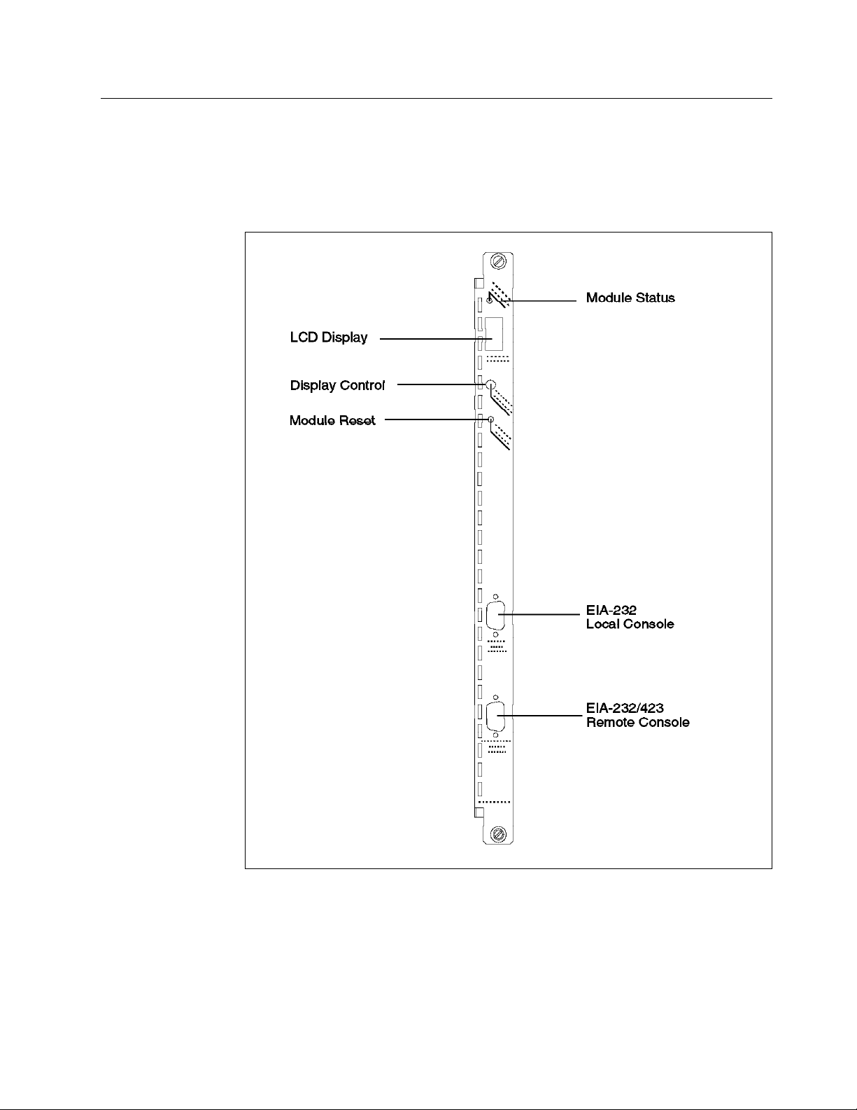
4.2 The Distributed Management Module (DMM)
The stand-alone DMM is a single-slot management module that has no facility
for carrying daughter cards.
The DMM has 1 module status LED, a 4-character display with a display control
toggle button and 2 serial port connectors as shown in Figure 15.
Figure 15. DMM Front Panel
4.2.1 Unpacking and Installing the DMM
Chapter 4. 8260 Distributed Management Architecture 39
Page 62
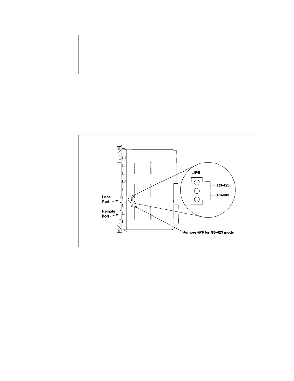
Caution
As always, great care should be taken when handling logic cards. The level
of static electricity that can build up in the human body can be thousands of
times greater than the very small switching voltage used in logic cards. A n
analogy would be connecting your Hi-Fi or TV set to 10,000 volts. I t wouldn′t
last long!
Remove the card from its shipping container and check it for damage.
There are 2 jumper blocks that may need to be changed. Namely, JP8 and JP9
as shown in Figure 16. These jumpers allow you to set the auxiliary DB-9
connector to RS-232 or RS-423. For the factory default, which is RS-232, the
jumper will be between pins 2 and 3 (the bottom 2 pins) of JP8. To select RS-423
mode, the jumper on JP8 should be changed to pins 1 and 2 (the upper pins).
For RS-423, the jumper MUST be installed on JP9. For RS-232, remove the
jumper from JP9.
Figure 16. Jumpering for the DMM DB-9 Ports
Holding the DMM by the faceplate, slide it into the slot in the 8260. Like all 8260
modules it can be hot plugged.
If the DMM has been installed correctly and is functioning the status LED should
come on. The LCD display should show
stby
module or
for a backup module.
4.2.2 DMM LED Indicators
Table 4 on page 41 shows the meaning of the status LED.
40 8260 Multiprotocol Intelligent Switching Hub
diag
then either
rdy
for the master
Page 63

Table 4. DMM Status LED
LED
name
Status Green OFF Power off or module failure
Color State Indicates
ON Power on and software functioning properly
Blinking Power on but diagnostics have failed
The LCD display and display control button are used to:
•
Display the current operating state of the module
•
Determine the network assignment of ports and 8260 modules in the hub
•
Display the version of the DMM microcode
The LCD display normally shows the module operating state. To display the
Vers
DMM microcode version, press the button until the display reads
, and one
second after releasing the button the version will be displayed. Table 5 shows
the possible states of the display.
Table 5. DMM LCD Display
Display Definition
Diag The DMM is running diagnostics
Rdy The DMM is the active (master) management module
Stby The DMM is in standby mode
Dnld New microcode is being downloaded
Vers Microcode level of the DMM
LED Displays when the controller LED test button is pressed
4.2.3 Console and Auxiliary Ports
There are two DB-9 ports on the faceplate of the DMM. The upper port is called
console
the
the DMM. This terminal is used to provide out-of-band management capability
for the 8260. See Table 6 for pinout of the cable used for attaching terminals to
this port.
Table 6. Console Port Pinouts
Pin # Signal Name
1 Carrier detect (CD)
2 Receive data (RX)
3 Transmit Data (TX)
4 Data terminal ready (DTR)
5 Signal ground (SG)
6 Data set ready (DSR)
7 Request to send (RTS)
8 Clear to send (CTS)
9 No connection
port and is used for attaching a terminal locally (or via a modem) to
Chapter 4. 8260 Distributed Management Architecture 41
Page 64

The lower port is the
auxiliary
port and can be jumpered for RS-232 or RS-423
operation. This port allows you to attach a terminal locally (or via modem) to
DMM. Note: The default is RS-232. See Table 7 on page 42 for the pinout of the
cables used for attaching terminals to the auxiliary port.
Table 7. Auxiliary Port Pinouts
Pin # Signal Name
1 Carrier detect (CD)
2 Receive data plus (RX+)
3 Transmit Data (TX)
4 Data terminal ready (DTR)
5 Signal ground (SG)
6 Data set ready (DSR)
7 Request to send (RTS)
8 Clear to send (CTS)
9 Receive Data Minus (RX-) if RS-423, otherwise no connection
Note
You can attach terminals to both the console and auxiliary port at the same
time, and both of them will be able to access the DMM simultaneously.
4.2.3.1 Modems for Connecting Terminals to DMM
The console port and auxiliary port can be used to connect a modem for remote
dial-in. The following requirements must be met:
1. The modem must be 100% Hayes compatible.
2. Any of the following baud rates may be used:
300, 1200, 2400, 9600, 19,200 or 38,400
3. The modem must be placed in Dumb/Auto Answer mode. This can be done
by entering the commands listed in Table 8 from a terminal directly attached
to the modem.
Table 8. Commands Required to Set Up the Modem for the Console Port
Commands # Definition
at&f [enter ] Restore factory defaults
at&d0 [enter ] Ignore changes in DTR status **
ats0=1 [enter ] Auto-answer on first ring
ats0? [enter ] Verify Auto-answer (should return 001
atq1 [enter ] Does not return result codes
at&W [enter ] Save this configuration
at&Y [enter ] Define this configuration as the default
at&d2 [enter ] Indicates hangup and assumes command state when
an On to Off transition of DTR occurs **
** If you issue the
must change the DTR parameter as defined by the ″at&d2″ command to ensure
42 8260 Multiprotocol Intelligent Switching Hub
Set Terminal Hangup Enable
command for modem use, you
Page 65

proper modem operation. See 4.2.4.3, “Configuring Terminal Settings for DMM”
on page 47 for description of Set Terminal Hangup command.
4.2.4 Configuring the DMM
The following table is a quick reference to the tasks required to configure the
DMM interface.
Table 9. DMM Interface Configuration Quick Reference
Procedure Command
Configure the terminal to match default
DMM settings
Configure DMM users SET LOGIN USER
Configure DMM terminal settings SET TERMINAL CONSOLE
Hub configuration SET CLOCK
Device configuration SET DEVICE NAME
IP configuration SET IP IP_ADDRESS
SNMP configuration SET COMMUNITY
Refer to the documentation provided
with the terminal
SET LOGIN ADMINISTRATOR
SET LOGIN SUPERUSER
SET LOGIN PASSWORD
SET LOGIN ACCESS
SET TERMINAL AUXILIARY
SET TERMINAL PROMPT
SET TERMINAL TIMEOUT
SET DEVICE LOCATION
SET DEVICE CONATCT
SET DEVICE DIAGNOSTICS
SET DEVICE MAC_ADDR_ORDER
SET DEVICE RESET_MASTERSHIP
SET DEVICE DIP_CONFIGURATION
SET DEVICE TRAP_RECEIVER
SET IP DEFAULT_GATEWAY
SET IP SUBNET_MASK
SET IP ACTIVE_DEFAULT_GATEWAY
SET ALERT AUTHENTICATION
SET ALERT CHANGE
SET ALERT CONSOLE_DISPLAY
SET ALERT HELLO
SET ALERT PORT_UP_DOWN
SET ALERT SCRIPT
Before your terminal and the DMM can communicate you must set up the
terminal parameters to match the DMM settings. The factory defaults and
options for the DMM are listed in Table 10. Initially the terminal must match the
defaults.
Table 10 (Page 1 of 2). DMM Terminal Defaults and Options
Parameter Factory
Default
Baud 9600 300,1200,2400,4800,9600,19200,38400
Data bits 8 7 or 8
Parity None Odd, Even or None
Options
Chapter 4. 8260 Distributed Management Architecture 43
Page 66

Table 10 (Page 2 of 2). DMM Terminal Defaults and Options
Parameter Factory
Default
Stop Bits 1 1 or 2
Options
Once the terminal has been configured press the Enter key. If the terminal has
been configured correctly the following message should be displayed:
8260A
Distributed Management Module (v2.10-H)
Login:
Figure 17. DMM Login Message
To log in as
superuser
at the
Login
prompt type in
system
and press the Enter
key. The module is shipped from the factory with a null password, so at the
Password
prompt press Enter.
At this stage you are logged into the 8260 with full access to all commands.
4.2.4.1 Configuring DMM Users
Three types of users can be used to access DMM:
•
User
This type of user can view the configuration of the 8260 and all the installed
modules and daughter cards. Additionally, this user can obtain statistics
about the various components of the network.
•
Administrator
This type of user can perform all the user functions. Additionally, this user
can modify the configuration of the hub and all the installed modules and
daughter cards.
•
Superuser
This type of user can perform all the functions of the administrator.
Additionally, this user can create new users and perform maintenance
functions such as downloading new software to the DMM and other modules.
The DMM is shipped from the factory with a single user defined. This user is
called
system
assigned to it.
and has superuser access. Also, it does not have any password
After logging in to DMM for the first time, it is strongly advised that for security
reasons you change the password for the superuser using the example given in
Figure 18 on page 45.
44 8260 Multiprotocol Intelligent Switching Hub
Page 67

8260A> set login password
Enter current session password for user ″system″:
Enter new password:
Verify - re-enter password:
User password changed.
8260A>
Figure 18. Changing Superuser Password
Note: DMM passwords are case sensitive.
You may define new login names with user, administrator and superuser
authority. Figure 19 shows an example of how to define a new superuser.
8260A> set login super_user
Confirm with Carriage Return
8260A> set login super_user
Enter current session password for user ″system″:
Enter Login Name: shabani
Enter Login Password: [new password]
Verify - re-enter password: [new password]
Login successfully entered.
Login account will not be activated until it is saved.
8260A>
Figure 19. Defining New DMM Superuser
Defining the other user types is identical to defining superuser, except that in the
user
or
set command you must specify
You can display the current users defined in your DMM, using the following
command:
administrator
8260A> show login
An example of the output from this command is shown in Figure 20 on page 46.
as the user type.
Chapter 4. 8260 Distributed Management Architecture 45
Page 68

8260A> show login
Login Table:
Index Login Name Access Active Sessions
----- --------------- -------------- --------------1 system Super User 1
2 shabani Super User 0
3 admin1 Administrator 0
4 user1 User 0
5 “not used“
6 “not used“
7 “not used“
8 “not used“
9 “not used“
10 “not used“
Active Login Sessions:
Login Name Session Type Session Time
---------- ------------ -----------system Remote Super User 0 days 00:15:27
8260A>
Figure 20. Display of Defined DMM Users
A superuser can delete entries for other users with the following command:
8260A> clear login {index | all}
Where
There can be up to a maximum of 10 users (any combination) defined in a DMM.
However, at any point in time, there can be only one user with write access
(administrator or superuser) logged in to a DMM. Therefore, if you try to log in
to DMM as an administrator or superuser, when there is already an
administrator (or a superuser) logged in to that DMM, you will be given a user
access. However, a superuser who is granted a user access in this way, can
use the example shown in Figure 21 on page 47 to force the termination of the
current session which has the write access (currently logged in administrator or
another superuser) and obtain the superuser access to DMM.
index
is as shown in Figure 20.
46 8260 Multiprotocol Intelligent Switching Hub
Page 69

Login:
Login: system
Password:
A user with Super User or Administrator Access is already logged in.
You are being logged in with User Access ...
Welcome to user service on 8260A.
8260A> set login access super_user
Super_user access granted.
8260A>
Figure 21. Forced Termination of Existing DMM Users
In this example, we tried to log in as a superuser and since there was already
an administrator logged in, we got a user access. After issuing the ″set login
access″ command, the administrator user was logged off and our user acquired
the superuser authorization.
4.2.4.2 Resetting Superuser Password to Factory Default
If you forget the superuser password for DMM, you may use the following
procedure to reset the password to factory default:
•
Try to log in to DMM using the superuser ID.
•
When prompted for the password, enter
•
Your login request will be rejected and you will be prompted to enter the
user ID again. This time, enter
•
When prompted for the password, enter
•
Immediately press the
reset
force
button on the DMM.
force
.
as the user ID.
force
.
Note that the above procedure will result in the following:
•
Restores the ″system″ password to nulls.
•
Resets DEVICE and TERMINAL settings to factory default.
•
All the other LOGIN entries, other than SYSTEM are cleared.
4.2.4.3 Configuring Terminal Settings for DMM
The DMM provides the following commands to allow you to customize your
terminal connection:
•
Set Terminal Console
This command allows you to set the following communications parameters
for the DMM to communicate with your terminal:
− Baud
This parameter allows you to set the baud rate at which the DMM will
send and receive data. For example, the following allows you to change
the baud rate to 9600.
8260> set terminal console baud 9600
Chapter 4. 8260 Distributed Management Architecture 47
Page 70

Note: The baud rate specified in this command must match the settings
of your terminal; otherwise, after issuing this command, the
communication between the terminal and DMM will be lost. In that case,
you must change the setting of your terminal before you can reestablish
the communication.
− Data_bits
This parameter allows you to set the number of data bits used by DMM
for communication with your terminal. The following command allows
you to change the number of data bits to 8.
8260> set terminal console data_bits 8
Note: The number of data bits specified in this command must match
the settings of your terminal; otherwise, after issuing this command, the
communication between the terminal and DMM will be lost. In that case,
you must change the setting of your terminal before you can reestablish
the communication.
− Stop_bits
This parameter allows you to set the number of stop bits used for
communication between your terminal and the DMM port. The following
command allows you to change the number of stop bits to 2.
8260> set terminal console stop_bits 2
− Parity
This parameter allows you to set the parity setting used by DMM for
communication with your terminal. For example, the following command
allows you to change parity for DMM to even:
8260> set terminal console parity even
Note: The parity setting specified in this command must match the
settings of your terminal; otherwise, after issuing this command, the
communication between the terminal and DMM will be lost. In that case,
you must change the setting of your terminal before you can reestablish
the communication.
− Mode
This command allows you to select which one of the following methods
will be used by the DMM to communicate with the device attached to its
port:
- Command-line parser
This setting allows DMM to communicate with a direct or modem
attached device emulating an ASCII terminal. To use the
command-line parser on the DMM port, you must issue the following
command:
8260A> set terminal console mode command_line
- Serial Line Interface (SLIP)
This setting allows DMM to use SLIP to communicate with a TCP/IP
station attached to its port console or auxiliary port. An example of
the command to set the SLIP interface on the DMM port, is given
below:
8260> set terminal console mode slip 9.67.46.3
48 8260 Multiprotocol Intelligent Switching Hub
Page 71

In this example, 9.67.46.3 is the address of the TCP/IP station
attached to the DMM port.
To use SLIP, you must also perform the following tasks:
1. Assign an IP address to DMM for communication over the SLIP
interface. The following example defines 9.67.46.1 as the address
used by DMM over the SLIP interface:
8260> set ip ip_address 9.67.46.1 slip
2. Assign an IP subnet mask to be used by DMM for communication
over the SLIP interface. The following example defines
255.255.255.240 as the subnet mask used by DMM over the SLIP
interface:
8260> set ip ip_address ff.ff.ff.f0 slip
3. Define the default gateway to be used by DMM for
communication over the SLIP interface. The following example
defines 9.67.46.2 as the default gateway used by DMM over the
SLIP interface.
8260> set ip default_gateway 9.67.46.2 slip
An example of using the SLIP setting is when the workstation
attached to the DMM port is a TCP/IP station running a network
management application which allows you to manage DMM using
SNMP.
− Terminal_type
This command allows you to set the terminal type which will be used by
DMM for establishing Telnet sessions. An example of this command is
as follows:
8260> set terminal console terminal_type vt100
The terminal type set by this command is sent by DMM to the remote
device when you establish a Telnet session from DMM to the remote
device. This enables the remote device to send the proper control
sequence for communication with DMM.
− Hangup
This command allows you to configure DMM to automatically hang up
the modem (drop DTR) once you log out of the DMM. To do so, you must
issue the following command:
8260> set terminal console hangup enable
The default is
unauthorized user may pick up the last login session.
Note: You can specify the same parameters for the auxiliary port. All you
need to do is replace
above.
•
Set Terminal Prompt
disable
console
which means the modem will not hangup and an
with
auxiliary
in the example commands given
This command enables you to customize the prompt displayed by DMM
when you are connected to that DMM. An example of this command is as
follows:
8260> set terminal prompt 8260A>
Chapter 4. 8260 Distributed Management Architecture 49
Page 72

This option is very useful in identifying the DMM to which you are logged in.
The default prompt is ″8260>″. It is recommended that you use the same ID
for both the terminal prompt and the DMM device name. See 4.2.4.4, “
Configuring DMM Device” on page 50 for how to configure DMM device
name.
•
Set Terminal Timeout
This command is used to specify the amount of time the terminal will remain
active during the absence of keyboard activity. This command is used for
security, to ensure that an unattended DMM console will not remain logged
in for long periods. The default is ″0″ which means the terminal will never
timeout. An example of this command is as follows:
8260A> set terminal timeout 10
Note that the value specified in the above command is in minutes.
You can display the current settings for console and auxiliary port using the
following command:
8260> show terminal
An example of the output displayed by this command is shown in Figure 22.
Terminal Session Parameters:
Prompt: 8260A>
Timeout time: 0
Console Port Parameters:
Baud: 9600
Data bits: 8
Parity: NONE
Stop bits: 2
Hangup: ENABLED
Mode: COMMAND LINE
Terminal: VT100
Auxiliary Port Parameters:
Baud: 9600
Data bits: 8
Parity: NONE
Stop bits: 2
Hangup: DISABLED
Mode: SLIP Destination IP Address: 9.67.46.3
Terminal: VT100
8260>
Figure 22. Output from Show Terminal Command
4.2.4.4 Configuring DMM Device
The following commands are used to allow you to configure the DMM:
•
Set Clock
This command allows you to set the time, day and date for the DMM. The
following is an example of using this command:
8260> set clock 15:45 95/1/19 Thursday
50 8260 Multiprotocol Intelligent Switching Hub
Page 73

This command sets the clock to 3:45 p.m., Thursday, Jan 19th, 1995. T he
clock is driven by an internal battery which is designed to last for 10 years.
•
Set Device
This command allows you to configure the following for DMM:
− Device name
This command allows you to configure a name for DMM. It is
recommended that each DMM in the network be assigned a unique
name. The name can be a maximum of 31 characters long. It is a good
idea to make sure that the name of the DMM and the prompt of the
terminal which is directly attached to it match each other.
8260A
The following command assigns the device name of
8260> set device name
> Enter device name:
> 8260A
Device name changed.
8260A>
Figure 23. Set Device Name Command for DMM
− Device location
This command allows you to describe the location of the 8260 in which
this DMM is installed. An example of this command is as follows:
to this DMM:
8260A> set device location
Enter one line of text:
> ITSO LAB, Building 657, Raleigh
Location changed.
8260A>
Figure 24. Set Device Location Command for DMM
Note that you can enter up to 78 alphanumeric characters to specify the
location of the DMM.
− Device contact
This command allows you to specify the name of the person responsible
for maintaining the 8260 in which this DMM is installed. An example of
this command is as follows:
8260A> set device contact
Enter one line of text:
> Mohammad Shabani, 301-2339
Contact changed.
8260A>
Figure 25. Set Device Contact Command for DMM
Note that you can enter up to 78 alphanumeric characters to specify the
contact name for the DMM.
− Device diagnostics
Chapter 4. 8260 Distributed Management Architecture 51
Page 74

The factory default is for the DMM to run through a full set of diagnostics
each time it is rebooted. By using the following command you can make
the DMM bypass the diagnostics and boot up faster:
8260A> set device diagnostics disable
− MAC address order
In general, Ethernet devices uses canonical address format, whereas
token-ring devices use a non-canonical address format. However, DMM
is shipped from the factory to display all the addresses in canonical
format regardless of the type of originating station. For example, with
canonical setting for DMM, if we display the current ARP table entries of
DMM, the result will be as shown in Figure 26.
8260A> show ip arp_cache
IP ARP Cache :
Interface Address Physical Address
--------- --------- ----------------
4 9.67.46.46 08-00-5a-13-39-6f
5 9.67.46.237 02-00-00-c0-cc-6c
5 9.67.46.238 08-00-5a-13-55-93
8260A>
Figure 26. Output from Show ARP_Cache Command with Canonical Setting
In this example 9.67.46.46 is an Ethernet attached station whereas
9.67.46.237, and 9.67.46.238 are both token-ring attached stations. A s can
be seen, all the addresses are shown in canonical format.
You may use the following command to set the non-canonical format to
be used by DMM:
8260A> set device mac_addr_order noncanonical
After issuing the above command, the current ARP table will be
displayed as shown in Figure 27.
8260A> show ip arp_cache
IP ARP Cache :
Interface Address Physical Address
--------- --------- ---------------0
4 9.67.46.46 10-00-5a-c8-9c-f6
5 9.67.46.237 40-00-00-03-33-36
5 9.67.46.238 10-00-5a-c8-aa-c9
8260A>
Figure 27. Output from Show ARP_Cache Command with Non-Canonical Setting
You may use this command to set the address format used by DMM to
be the same as the address format that you are most accustomed to.
− Reset mastership
52 8260 Multiprotocol Intelligent Switching Hub
Page 75

You can configure DMM to force a mastership election when it is
inserted into a hub. This option may be used to ensure that the DMM
gets the opportunity to obtain the appropriate authority after it is
removed and inserted back into the hub. The command to enable the
forcing of mastership is as follows:
8260A> set device reset_mastership enable
− DIP configuration
Each 8260 media module has a set of DIP switches which allow you to
configure how the module should operate. Also, each module has a
non-volatile RAM which is used to store the configuration information
that you set for the module via DMM commands. This configuration
information is sent by DMM to the module when the module is installed
in the hub.
Once installed, the 8260 module will be configured according to the
following procedure:
- The 8260 module attempts to configure itself from either its DIP
switch settings or the onboard NVRAM. The setting of one of the DIP
switches on the module determines if the module should try to use
its DIP switch settings or the onboard NVRAM.
- If a Master DMM is installed, the requested configuration is
submitted for approval:
•
If the DMM has a saved configuration for module/slot, it overrides
the requested configuration.
•
If the DMM does not have a saved configuration for the
module/slot, it checks the requested configuration for validity:
− If valid, the requested configuration is used.
− If not valid, or DIP switches are used, the module is isolated
and ports are disabled.
- If no Master DMM is installed, the module tests the requested
configuration for validity:
•
If valid, the requested configuration is used.
•
If not valid, or not present (NVRAM selected, but has no
configuration), the module is isolated and ports are disabled.
The above procedure will happen if you have issued the following
command:
8260A> set device dip_configuration disable
However, you may configure your hub to bypass the above procedure
and force the DIP switch settings on the module to be used all the time.
To do so, you must issue the following command:
8260A> set device dip_configuration enable
− Trap receiver
You can enable DMM to receive traps from the other SNMP devices
(such as other 8260 hubs) in your network. To do so, you must issue the
following command:
8260A> set device trap_receiver enable
Chapter 4. 8260 Distributed Management Architecture 53
Page 76

Note that for your DMM to receive traps from the other stations, your
DMM must be defined as a trap receiver in the community table of the
other stations.
After setting all the parameters for DMM you must ensure that you save
them using the following command:
8260A> save device
You can display the current device settings for DMM using the following
command:
8260A> show device
An example of the output from this command is shown in Figure 28.
8260A> show device
IBM 8260 Distributed Management Module (DMM) v2.10-H pSOS+ SNMP
Name: 8260A
Location:
ITSO LAB, Building 657, Raleigh
For assistance contact:
Mohammad Shabani, 301-2339
Operational Version: v2.10-H Boot Version: v1.01
Serial Number: 1067067 Service Date: 94/04/21 Restarts: 59
Dip Configuration: DISABLED Diagnostics: DISABLED
Reset Mastership: ENABLED Trap Receive: ENABLED
MAC Address Order: NONCANONICAL
8260A>
Figure 28. Output from Show Device Command
4.2.4.5 Configuring DMM IP Parameters
As mentioned earlier in this chapter, DMM will use the IP stack provided by
T-MAC and E-MAC to communicate with the other IP stations. For DMM to use
the IP stack of E-MAC and T-MAC, you must first perform the following tasks:
1. Assign the following parameter for one or more of the backplane segments:
•
IP address
For example, to assign an IP address of 9.67.46.235 to the token_ring_10
segment on the ShuntBus, you must use the following command:
8260A> set ip ip_address 9.67.46.235 token_ring_10
•
Subnet mask
For example, to assign a subnet mask of 255.255.255.240 to the
token_ring_10 segment on the ShuntBus, you must use the following
command:
8260A> set ip subnet_mask ff.ff.ff.f0 token_ring_10
•
Default gateway
54 8260 Multiprotocol Intelligent Switching Hub
Page 77

For example, to assign a default gateway of 9.67.46.238 to the
token_ring_10 segment on the ShuntBus, you must use the following
command:
8260A> set ip default_gateway 9.67.46.238 token_ring_10
Note that DMM will use the IP address assigned to a segment to
communicate through that segment. Therefore, if you have assigned IP
addresses to more than one backplane segment, your DMM, effectively, has
multiple addresses (one in each segment).
You can display the IP parameters which are currently assigned in your 8260,
using the following command:
8260A> show ip
An example of the output from this command is shown in Figure 29.
8260A> show ip
Active Default Gateway : 127.0.0.1
Operational Active Default Gateway : 9.67.46.46
Index Network Slot IP Address Subnet Mask Default Gateway
----- ------------- ---- ----------- ----------- ---------------
1 ETHERNET_1 N/A 9.67.46.41 ff.ff.ff.f0 9.67.46.46
2 TOKEN_RING_10 N/A 9.67.46.235 ff.ff.ff.f0 9.67.46.238
3 SLIP N/A 9.67.46.1 ff.ff.ff.f0 9.67.46.2
8260A>
Figure 29. Output from Show IP Command
In this example, our DMM is assigned three IP addresses:
•
9.67.46.1 for slip connection through the console/auxiliary port
•
9.67.46.46 for connection through Ethernet_1
•
9.67.46.238 for connection through token_ring_10
You can clear any of the IP entries assigned to DMM using the following
command:
8260A> clear ip index
Where
2. When there are multiple default gateways defined, you may select one
gateway, known as the active default gateway, that will be used by DMM to
send the packets to unknown destinations. You can use the following
command to select the active default gateway:
8260A> set ip active_default_gateway 9.67.46.238
index
is the number of the network shown in Figure 29.
If you do not select the active default gateway, by default, the active default
gateway is the default gateway assigned to the first interface that you have
assigned to your DMM. For example, for the DMM shown in Figure 29, the
active default gateway would have been 9.67.46.46 had we not defined
9.67.46.238 as the active default gateway.
Chapter 4. 8260 Distributed Management Architecture 55
Page 78

3. After configuring the IP address(es) for DMM, you must assign an E-MAC or
T-MAC to any backplane through which the DMM is going to communicate
using IP. For information about how to assign E-MAC or T-MAC to a
backplane segment, please refer to 4.4, “MAC Daughter Cards” on page 61.
4.2.4.6 Configuring DMM SNMP Parameters
The DMM acts as an agent in an SNMP managed environment, enabling you to
manage the 8260 using an SNMP manager. The DMM supports SNMP by
responding to SNMP requests from the SNMP managers and generating SNMP
traps which can be sent to SNMP managers.
There is a community table in DMM which allows you to define the IP address
and community name of up to 10 SNMP managers. Each of these SNMP
managers can have one of the following attributes assigned to it:
•
Read only
Allows the specified SNMP manager to read SNMP variables via the GET
command.
•
Read-write
Allows the specified SNMP manager to read and write SNMP variables via
the GET and SET commands.
•
Trap
Enables DMM to send traps to the specified SNMP manager.
•
Read trap
Allows the specified SNMP manager to read SNMP variables and receive
traps.
•
All
Allows the SNMP manager to read SNMP variables, change the variables via
the SET command and receive traps from DMM.
The following command is an example of how to define an SNMP manager
9.67.46.45
with the community name of
public
to be able to perform
all
functions:
8260A> set community public 9.67.46.45 all
You can display the contents of the community name using the following
command:
8260A> show community
An example of the output from this command is shown in Figure 30 on page 57.
56 8260 Multiprotocol Intelligent Switching Hub
Page 79

8260A> show community
Index Community Name IP Address Access
----- -------------------- --------------- -----1 public ***.***.***.*** Read-Only
2 public 9.24.104.23 All
3 public 9.24.104.70 All
4 public 9.67.46.45 All
5 [empty]
6 [empty]
7 [empty]
8 [empty]
9 [empty]
10 [empty]
8260A>
Figure 30. Output from Show Community Command
You can clear entries from the community table using the following command:
8260A> clear community index
Where
index
is the number of the entry as shown in Figure 30.
DMM sends alerts (traps) when certain events occur. You can use the SET
ALERT command to enable/disable specific alert features. These alert features
are:
•
Authentication
DMM sends an alert when an unauthorized access is attempted to DMM
using SNMP. You can enable DMM to send authentication traps using the
following command:
8260A> set alert authentication enable
•
Change
Any configuration change made in the hub results in DMM sending an alert.
You can enable DMM to send change traps using the following command:
8260A> set alert change enable
•
Hello
When DMM is activated, it sends one Hello trap every minute, 255 times until
a valid SNMP message is received. You can enable DMM to send Hello
traps using the following command:
8260A> set alert hello enable
•
Console_display
Allows you to enable trap display on the local console attached to DMM.
You can enable DMM to display traps on the local console using the
following command:
8260A> set alert console_display enable
•
Port_filter
Allows you to filter out unwanted port up/down messages on the local
console. To set the port_filter alert you can use the following command:
Chapter 4. 8260 Distributed Management Architecture 57
Page 80

8260A> set alert port_up_down {enable|disable|filter}
If you enable this option, all the port up and port down traps will be sent to
the local console. “disable,” prevents the traps from being displayed on the
local console. “filter” allows DMM to check the ALERT_FILTER setting for
each port for displaying/suppressing the port up and port down alters. The
ALERT_FILTER for each port can be set using the following example:
8260A> set port 2.1 alter_filter {enable|disable}
4.3 The EC-DMM (Ethernet Carrier - Distributed Management Module)
The EC-DMM is a single-slot management module that has the mounting ability
to carry up to 6 Ethernet MAC daughter cards.
The EC-DMM has 1 module status LED, a 4-character display with a display
control toggle switch, 24 Ethernet network status LEDs and 2 serial port
connectors. Figure 31 on page 59 shows the layout of the DMM front panel.
58 8260 Multiprotocol Intelligent Switching Hub
Page 81

Figure 31. EC-DMM Front Panel
4.3.1 Installing the EC-DMM
Remove the card from its shipping container and check it for damage.
There are 2 jumper blocks that may need to be changed, JP8 and JP9. These
jumpers are shown in Figure 32 on page 60. These jumpers allow you to set the
auxiliary DB-9 connector to RS-232 or RS-423. For the factory default, which is
RS-232, the jumper will be between pins 2 and 3 (the bottom 2 pins) of JP8. To
select RS-423 mode, the jumper on JP8 should be changed to pins 1 and 2 (the
upper pins). For RS-423, the jumper must be installed on JP9. For RS-232,
remove the jumper from JP9.
Chapter 4. 8260 Distributed Management Architecture 59
Page 82
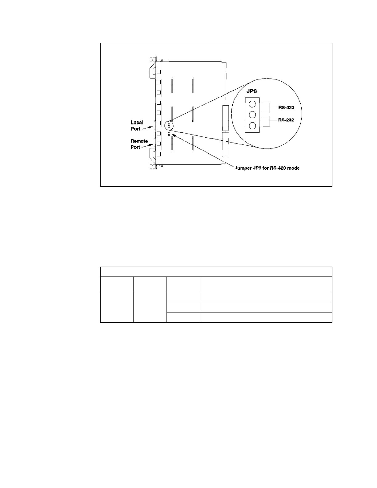
Figure 32. Jumpering for the EC-DMM DB-9 Ports
Holding the DMM by the faceplate, slide it into the slot in the 8260. Like all 8260
modules it can be hot plugged.
If the EC-DMM has been installed correctly and is functioning the status LED
should come on. The LCD display should show
master module or
4.3.2 EC-DMM LED Description
Table 11. EC-DMM Status LED
LED
name
Status Green OFF Power off or module failure
The LCD display and display control button are used to:
− Display the current operating state of the module.
− Determine the network assignment of ports and 8260 modules in the hub.
− Display the version of the EC-DMM microcode.
Color State Indicates
stby
for a backup module.
ON Power on and software functioning properly
Blinking Power on but diagnostics have failed
diag
then either
rdy
for the
The LCD display normally shows the module operating state. Each time the
display control button is pressed the character display cycles through each of
the networks. By using the network display LEDs on the EC-DMM and the 8260
media modules it is possible to see which modules and which ports are
assigned to a network.
For example, we have an 8260 24-port port switching module in slot 2, with ports
1, 3, 5 and 7 assigned to Ethernet_1 and a similar module in slot 4 with ports 15,
16, and 17 assigned to Ethernet_5. I f the control button is pressed once the LCD
display will change from
Ethernet_1 on the DMM will turn on. The LEDs for ports 1, 3, 5 and 7 on the 8260
60 8260 Multiprotocol Intelligent Switching Hub
rdy
to E1. The Ethernet network status LED for
Page 83

Ethernet media module in slot 2 will also turn on to indicate those ports have
been assigned to Ethernet_1. I f there were more media modules with ports
assigned to Ethernet_1 their port LEDs would also turn on. Because Ethernet_2,
3 and 4 are not being used, the next time the button is pressed the LCD display
will jump to ″E5″, the DMM network status LED for Ethernet 5 will turn on and the
LEDs for ports 15, 16 and 17 on the 8260 Ethernet media module in slot 4 will
also turn on to indicate those ports are assigned to Ethernet_5.
To display the EC-DMM microcode version, press the button until the display
reads Vers. One second after releasing the button the version will be displayed.
Table 12 shows the possible states of the display.
Table 12. EC-DMM LCD Display
Display Definition
Diag The EC-DMM is running diagnostics
Rdy The EC-DMM is the active (master) management module
Stby The EC-DMM is in standby mode
Dnld New microcode is being downloaded
E1-E8,EI Shows active networks only; EI for isolated
TR1-10,TRI Shows active networks only; TRI for isolated
F1-F4,FI Shows active networks only; FI for isolated
Vers Microcode level of the DMM
LED Displays when the controller LED test button is pressed
4.4 MAC Daughter Cards
To be able to monitor the network traffic activity on the backplane segments, as
well as to be able to communicate with other stations using IP, DMM requires
the services provided by MAC daughter cards.
These daughter cards connect to the networks, listen to the traffic flow and pass
traffic information back to the DMM. They also provide the DMM with the
interface to the networks on the backplane so that it can communicate with the
other stations on that network.
The MAC daughter cards are protocol specific cards and at the time of writing
this book the following two types of MAC daughter cards were available:
•
The E-MAC (Ethernet - Media Access Card)
•
The T-MAC (Token-ring - Media Access Card)
These daughter cards can be installed on the media modules that use the same
protocol. That is, T-MACs can be installed on token-ring media modules, and
E-MACs can be installed on Ethernet media modules. Each token-ring or
Ethernet media module can accommodate installation of one MAC daughter card
(Ethernet 40-port module allows the installation of two MAC daughter cards).
Additionally, the E-MACs can be installed on the EC-DMM. Each EC-DMM can
accommodate the installation of up to 6 E-MACs.
Regardless of where the MAC daughter cards are installed, they can be
assigned to any of the backplane segments. However, to assign a MAC
Chapter 4. 8260 Distributed Management Architecture 61
Page 84

daughter card to an isolated segment on a media module, the MAC daughter
card must be installed on that media module.
Note
E-MACs installed on EC-DMM can collect detailed statistical information
all
about
statistical information includes network as well as module and port level
information. This information is collected for both 8260 and 8250 Ethernet
modules (note that 8250 Ethernet modules may attach to Ethernet_1 thru
Ethernet_3 segments only).
The E-MACs installed on the media modules can collect full statistics
(network, module and port level statistics) for Ethernet_4 thru Ethernet_8
segments only. For Ethernet_1 thru Ethernet_3, they can only collect network,
module and port level statistics for 8260 Ethernet modules, but for the 8250
modules attached to these segments they can only collect network level
statistics and cannot report module or port level statistics. This is due to the
use of parallel addressing by the 8250 modules. Therefore, if you are
planning to monitor Ethernet_1 thru Ethernet_3 segments which include 8250
Ethernet modules, you must ensure that the E-MACs used to monitor those
segments are installed on EC-DMM.
Because of the possibility of installing MAC daughter cards on the 8260 modules,
the 8260 modules are identified by
and subslot identifiers are used in DMM commands to refer to the media
modules, management modules or daughter cards. The following is a summary
of how to identify the slot and subslot for each media module, management
module, and daughter card:
the ShuntBus and Enhanced TriChannel Ethernet segments. This
slot
and
subslot
identifiers. Note that the slot
1. Each media module is always considered to be on the first subslot of the slot
on which the media module is installed. For example, if you have installed a
24-port Ethernet media module in slot 2, this will be identified as module 2.1
(slot 2, subslot 1). This is regardless of the fact that the media module may
or may not have a MAC daughter card installed on it.
2. If a MAC daughter card is installed on a media module, the daughter card is
considered to be in subslot 2 of the slot in which the media module is
installed. For example, if the above mentioned 24-port media module had an
E-MAC installed on it, the E-MAC will be considered to be module 2.2,
whereas the 24-port module is 2.1. Figure 33 is an example of the output if
you display all the modules on slot 2.
8260A> show module 2.all
Slot Module Version Network General Information
----- --------------- ------- ------------- -------------------
02.01 1 E24PS-6/8 v1.00 PER_PORT Port(s) are down
02.02 E-MAC v2.00 ETHERNET_1
8260A>
Figure 33. 24-Port Ethernet Module with E-MAC
62 8260 Multiprotocol Intelligent Switching Hub
Page 85

3. The stand-alone DMM is always considered to be on the first subslot of the
slot in which the stand-alone DMM is installed. Note that a stand-alone
DMM does not have the housing for a MAC daughter card.
4. In the case of an EC-DMM which does have the housing for 6 E-MACs, the
EC-DMM module is always considered to be in subslot 1 of the slot in which
the EC-DMM is installed. Also, the DMM part of EC-DMM is always
considered to be in subslot 8. If there are any E-MAC daughter cards
installed in the EC-DMM, they will be considered to be in subslots 2 thru 7 of
the slot on which EC-DMM is installed. Figure 34 shows how the slot and
subslot IDs are used on an EC-DMM.
Figure 34. EC-DMM Slots and Subslots
For example, in our 8260, we had an EC-DMM installed in slot 1. This
module had an E-MAC installed on the first position (DB1 as shown in
Figure 34). If w e display this module, the result would be as shown in
Figure 35.
8260A>
8260A> show module 1.all
Slot Module Version Network General Information
----- --------------- ------- ------------- -------------------
01.01 1 EC-DMM v1.00 N/A
01.02 E-MAC v2.00 ETHERNET_3
01.08 1 DMM v2.10-H N/A Master Management Module
8260A>
Figure 35. EC-DMM Display
Chapter 4. 8260 Distributed Management Architecture 63
Page 86

4.4.1 Ethernet MAC Daughter Card (E-MAC)
E-MAC is a MAC daughter card which can be installed on an EC-DMM or
Ethernet media modules. Figure 36 shows how you can install up to 6 E-MACs
on a single EC-DMM.
Figure 36. EC-DMM with Up to 6 EMACs
In addition to the DMM with an interface to the network, E-MAC allows you to
collect statistics about the Ethernet segment to which it is attached. The
statistics which are collected by E-MAC are passed to DMM which allows you to
display them locally or access them (in-band) through an application such as
RMonitor for AIX. Note that the communication between DMM and the E-MAC
installed on the 8260 media modules is via MLAN. For more information about
MLAN, please refer to 2.5.1.1, “The Management LAN (MLAN)” on page 26.
The E-MAC supports collection of a subset of the RMON statistics. For
information about RMON, and the E-MAC support it, please refer to Chapter 10,
“8260 RMON Support” on page 191.
4.4.1.1 Configuration E-MAC
Once you have installed an E-MAC card, you must perform the following
configuration steps:
1. Assign IP parameters to the segment to which the E-MAC is going to be
attached, as described in 4.2.4.5, “Configuring DMM IP Parameters” on
page 54.
64 8260 Multiprotocol Intelligent Switching Hub
Page 87

2. Use the following command to set an appropriate
interface on the E-MAC:
8260A> set module 2.2 interface {enable|disable|standby}
mode
for the network
The valid
•
•
•
3. Assign the E-MAC to the desired segment using the following example:
options
Enable
This option allows the network interface on the E-MAC to be activated
automatically when attached to a backplane segments. An active E-MAC
will be able to send and receive data and collect statistics about the
segment to which it is attached. An active E-MAC, when connected to a
backplane segment, assumes all the IP parameters assigned to that
segment.
Disable
This prevents the network interface on the E-MAC from being activated
when attached to a backplane segment.
Standby
This allows the E-MAC to assume the role of backup for the active
E-MAC when it is attached to a LAN segment on the backplane. The
standby E_MAC will take over from an active E-MAC on that segment,
should the active E-MAC fail. When a standby E-MAC takes over the role
of the active E-MAC on the segments, it assumes all the IP parameters
assigned to the segment. You may use this option when you have two
E-MACs attached to the same segment and want one of them to act as a
backup for the active E-MAC.
for this command are:
8260A> set module 2.2 network ethernet_1
If you try to assign an E-MAC with
already has an active E-MAC, your command will be rejected as shown in
Figure 37.
enabled
interface to a segment which
8260A> set module 1.2 network ethernet_1
Interface module 2.2 already enabled for this network
Multiple Enabled Interface cards cannot be on the same network
Command aborted
8260A>
Figure 37. Assigning E-MAC to a Segment with an Active E-MAC
4. If you are planning to use the RMON support provided by E-MAC, you may
perform some additional steps as discussed in 10.6.4, “Collecting and
Displaying RMON Groups Using E-MAC” on page 218.
You can use the following example to obtain information about the E-MAC and
how it′s configured:
8260A> show module 1.2 verbose
Chapter 4. 8260 Distributed Management Architecture 65
Page 88

In this example, the E-MAC is installed in the first subslot of the EC-DMM which
is installed in slot 1 of the 8260. The output from this command is shown in
Figure 38 on page 66.
8260A> show module 2.2 verbose
Slot Module Version Network General Information
----- --------------- ------- ------------- -------------------
02.02 E-MAC v2.00 ETHERNET_1
E-MAC: Ethernet Network Monitor Card
Boot Version: v1.01
IP Address: 9.67.46.41
Subnetwork Mask: ff.ff.ff.f0
Default Gateway: 9.67.46.46
Station Address: 10-00-f1-0c-c0-f7
Interface Mode: ENABLED
RMON Host Statistics: DISABLED
RMON Probe Mode: DISABLED
Interface Number: 4
8260A>
Figure 38. Output from E-MAC Display
Note that this example shows that the E-MAC has a MAC address (shown in
non-canonical format in our display because of the DMM setting). This display
also shows the IP address, subnet mask, and default gateway for E-MAC which
is that of the Ethernet segment to which this E-MAC is assigned.
4.4.2 Token-Ring MAC Daughter Card (T-MAC)
The T-MAC must be mounted on an 8260 token-ring media module. This is
because at this stage there is no token carrier DMM. The T-MAC performs the
same functions for token-ring as the E-MAC does for Ethernet. It gathers
network and port statistics and transmits them to the DMM via the MLAN.
Each token-ring media module has the housing to install one T-MAC.
In addition to providing DMM with the interface to the backplane segments,
T-MAC allows you to collect statistics about the token-ring segment to which it is
attached. The statistics which are collected by T-MAC are passed to DMM (over
MLAN) which allows you to access them locally or in-band through an
application such as RMonitor for AIX. T-MAC supports collection of a subset of
RMON statistics. For information about RMON, and the T-MAC support for it,
please refer to Chapter 10, “8260 RMON Support” on page 191.
4.4.2.1 Configuring T-MAC
Once you have installed the T-MAC card, you must perform the following
configuration steps:
1. Assign IP parameters to the segment to which the T-MAC is going to be
attached, as described in 4.2.4.5, “Configuring DMM IP Parameters” on
page 54.
66 8260 Multiprotocol Intelligent Switching Hub
Page 89

2. If you are planning to use LAAs within your network, use the following
example to assign a locally administered address to T-MAC:
8260A> set module 6.2 locally_administered_address 40-00-00-82-60-a1
Note that assigning a locally administered address to T-MAC, does not result
in the T-MAC using the assigned address automatically. You must use the
following command to choose which type of MAC address (locally
administered or universal) is to be used by the T-MAC:
8260A> set module 6.2 mac_address_type burned_in
or
8260A> set module 6.2 mac_address_type locally_administered
3. Use the following example to enable or disable early token release support
of the T-MAC
8260A> set module 6.2 early_token_release {enable | disable}
4. Specify if the T-MAC is going to contend to become the active monitor, using
the following example:
8260A> set module 6.2 monitor_contention {enable | disable}
This parameter affects the way in which the T-MAC participates in the token
claiming process as follows:
•
If you enable monitor contention, the T-MAC will always try to contend to
become an active monitor.
•
If the monitor contention is disabled and another station on the ring
detects the absence of an active monitor and initiates the token claiming
process, the T-MAC will not contend to become an active monitor.
•
If the T-MAC is the first station which detects the absence of an active
monitor, it will contend to become the active monitor, regardless of the
setting of the monitor contention parameter.
5. Use the following example command to set an appropriate
network interface on the T-MAC:
8260A> set module 6.2 interface {enable|disable|standby}
The valid
•
•
•
options
for this command are:
Enable
This option allows the network interface on the T-MAC to be activated
automatically when attached to a backplane segment. An active T-MAC
will be able to send and receive data and collect statistics about the
segment to which it is attached. An active T-MAC, when connected to a
backplane segment, assumes all the IP parameters assigned to that
segment.
Disable
This prevents the network interface on the T-MAC from being activated
when attached to a backplane segment.
Standby
This allows the T-MAC to assume the role of backup for the active
T-MAC when it is attached to a LAN segment on the backplane. The
standby T-MAC will take over from an active T-MAC on that segment,
should the active T-MAC fail. When a standby T-MAC takes over the role
of the active T-MAC on the segment, it assumes all the IP parameters
assigned to that segment. You may use this option when you have two
mode
for the
Chapter 4. 8260 Distributed Management Architecture 67
Page 90

T-MACs attached to the same segment and want one of them to act as a
backup for the active T-MAC.
6. Assign the T-MAC to the desired segment using the following example:
8260A> set module 6.2 network token_ring_10
If you try to assign a T-MAC with
already has an active T-MAC, your command will be rejected as shown in
Figure 39.
enabled
interface to a segment which
8260A> set module 8.2 network token_ring_10
Interface module 6.2 already enabled for this network
Multiple Enabled Interface cards cannot be on the same network
Command aborted
8260A>
Figure 39. Assigning T-MAC to a Segment with an Active T-MAC
7. If you are planning to use RMON support provided by T-MAC, you may
perform the additional steps described in 10.6.6, “Collecting and Displaying
RMON Groups Using T-MAC” on page 230.
You can use the following example to obtain information about the T-MAC and
how it′s configured:
8260A> show module 6.2 verbose
In this example, the T-MAC is installed on the 18-port active per-port switching
token-ring media module which is installed in slot 6. The output from this
command is shown in Figure 40 on page 69.
68 8260 Multiprotocol Intelligent Switching Hub
Page 91

8260A> show module 6.2 verbose
Slot Module Version Network General Information
----- --------------- ------- ------------- -------------------
06.02 T-MAC v2.00 TOKEN_RING_10
T-MAC: Token Ring Network Monitor Card
Boot Version: v2.00
IP Address: 9.67.46.235
Subnetwork Mask: ff.ff.ff.f0
Default Gateway: 9.67.46.238
Station Address: 10-00-f1-0b-09-5f
Locally Administered Address: 40-00-00-82-60-a1
MAC Address Type: BURNED-IN
Interface Mode: ENABLED
RMON Groups: DISABLED
Surrogate Groups: DISABLED
Dot5 Group: DISABLED
RMON Host Statistics Collection: DISABLED
RMON MAC Layer Statistics Collection: DISABLED
RMON Promiscuous Statistics Collection: DISABLED
RMON Ring Station Statistics Collection: DISABLED
RMON Source Routing Statistics Collection: DISABLED
Monitor Contention: ENABLED
Adapter Status: OPENED
Adapter Microcode Version: 00 00 01 c1 e3 f1 f7 c3 f1 40
Early Token Release: DISABLED
Internal Wrap: DISABLED
External Wrap: DISABLED
Interface Number: 5
8260A>
Figure 40. Output from T-MAC Display
Note that this example shows that although we have assigned a locally
administered MAC address to T-MAC, it is still using the burned-in MAC
address. This display also shows the IP address, subnet mask, and default
gateway for T-MAC which is that of the token-ring segment to which this T-MAC
is assigned.
4.5 Managing 8260 Using DMM and 8250 xMM
This section will explore managing the 8260 hub and its networks using different
combinations of 8260 and 8250 management and media modules. There are
three possible scenarios for managing an 8260:
1. Managing 8260 with only a DMM
2. Managing 8260 with only 8250 management module(s) and no DMM
3. Managing 8260 with a DMM as well as 8250 management module(s)
Note
The second method is not recommended but will be looked at.
Chapter 4. 8260 Distributed Management Architecture 69
Page 92

4.5.1 Managing 8260 with DMM
The following is the summary of the capabilities of DMM when managing an 8260
which is populated with both 8260 and 8250 modules:
1. DMM can be used to fully configure the 8260 modules as well as the 8250.
2. DMM in conjunction with E-MAC can be used to monitor the network, module
and port-level statistics for the Ethernet segments consisting of 8250 and
8260 modules. However, to be able to monitor the module and port-level
statistics for the 8250 modules assigned to Ethernet_1 thru Ethernet_3, the
E-MAC must be installed on an EC-DMM.
3. DMM in conjunction with T-MAC can be used to monitor and collect network,
module and port-level statistics about the 8260 modules assigned to the
token-ring segments on the ShuntBus.
4. DMM and T-MAC cannot be used to monitor token-ring segments on the
Enhanced TriChannel. To collect statistics about a token-ring segment on
the Enhanced TriChannel, you must use an 8250 TRMM assigned to that
segment. If multiple token-ring segments on the Enhanced TriChannel need
to be monitored simultaneously, you need one TRMM for each network.
5. DMM cannot be used to monitor FDDI segments on the Enhanced
TriChannel. To collect statistics for an FDDI segment on the Enhanced
TriChannel, you must use an 8250 FMM assigned to that segment. If multiple
FDDI segments on the Enhanced TriChannel need to be monitored
simultaneously, you need one FMM for each network.
4.5.2 Managing 8260 with 8250 xMM
The following is a summary of the capabilities of an 8250 xMM when acting as
the master management module in an 8260 which is populated with both 8260
and 8250 modules:
1. Each 8250 xMM requires its own payload slot.
2. The 8250 xMM can be used to configure and manage the 8250 media
modules installed in the 8260.
3. The 8250 xMM does not recognize and cannot configure the 8260 modules.
However, if you use the ″show concentrator″ command, it will report that the
slots occupied by the 8260 modules are populated by
4. The 8250 xMM assumes the active controller module occupies slot 17.
Because of this slot 17 cannot be used for a media module or a management
module and should be used for the right-hand boundary plate of the 8250
mounting kit.
5. Most of the functionality of the 8260 power and cooling subsystems is lost
when the 8260 is managed by an 8250 xMM. In this case, the controller
module is still able to manage the power and cooling subsystems but there
is no interface to enable you to set the parameters for it to perform these
functions as you desire. For example, it is not possible to set power classes
or set power fault tolerant mode.
6. The backup controller module (if installed) is not recognized and reported by
the xMM; however, if it becomes the active controller module, it will be
recognized and will be reported to be in slot 17.
ONcore
modules.
7. Any segments on the Enhanced TriChannel (excluding Ethernet_4 thru
Ethernet_6) can be monitored using an appropriate xMM attached to that
70 8260 Multiprotocol Intelligent Switching Hub
Page 93
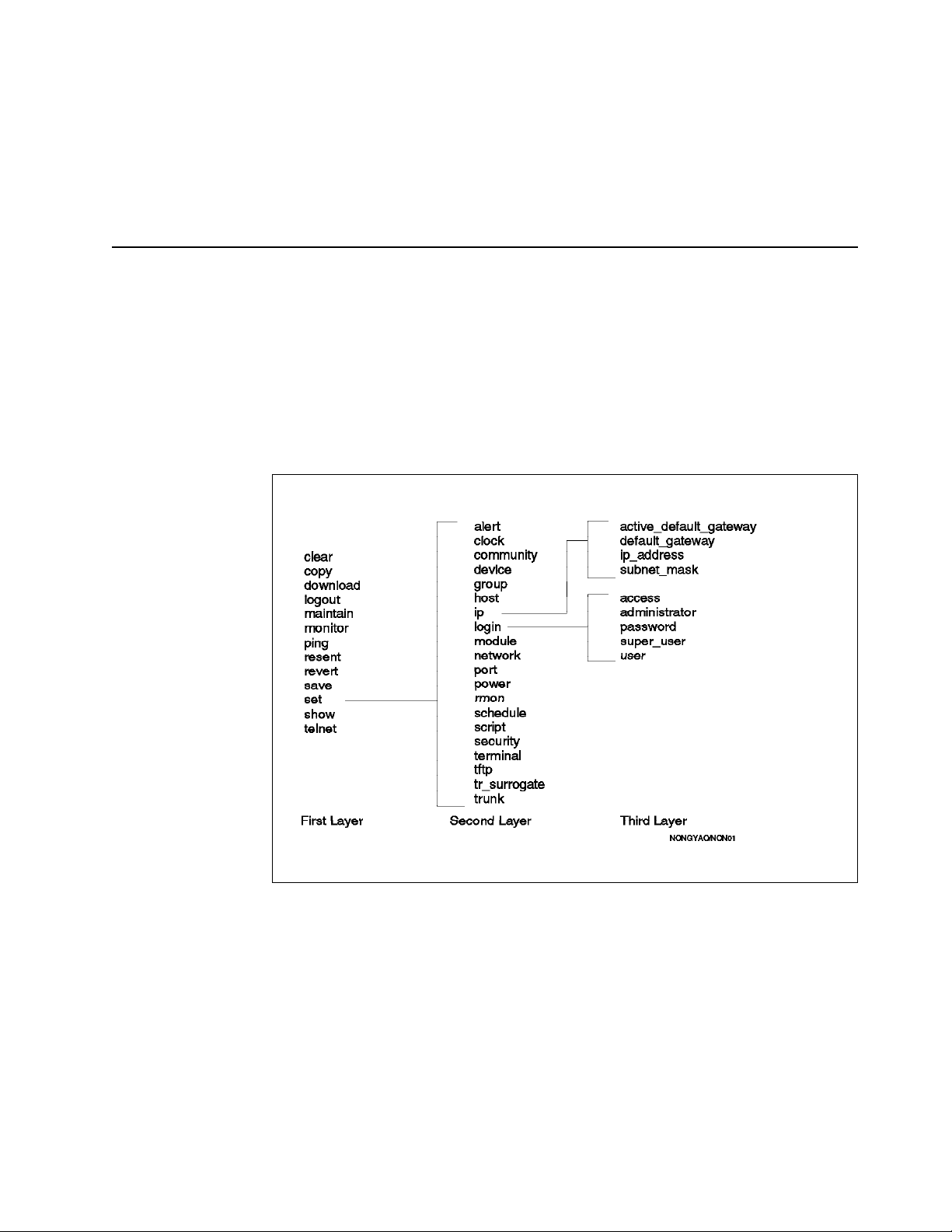
segment. If multiple 8250 networks need to be monitored simultaneously
then each network requires its own 8250 xMM.
8. The two previous points mean that the more monitoring required on 8250
networks the fewer payload slots are available for media modules.
9. ShuntBus based segments are not manageable by 8250 xMM.
4.6 Overview of Management and Control Commands
Commands used in the 8260 hub can be organized into hierarchical or layer like
structures. When you first log in to the 8260 hub with the
commands in the first layer will be available. Commands may have various
parameters or options associated with them. For example, in Figure 41, all
commands in the second layer are the available options associated with the
command. Default_gateway, ip_address and subnet_mask are the possible
ip
options associated with the
first layers in respectively.
option and the
set
system
command in the second and
user ID,
set
Figure 41. A Sample of Hierarchical Structure Command
In the remainder of this book, the DMM commands will be covered as we
discuss various components of the 8260.
Chapter 4. 8260 Distributed Management Architecture 71
Page 94

72 8260 Multiprotocol Intelligent Switching Hub
Page 95

Chapter 5. 8260 Intelligent Power Management Subsystem
The 8260 provides extensive power management functions that allow you to take
advantage of the modular load-sharing power supply system available on the
8260.
This chapter provides detailed information about the power management
subsystem of the 8260.
5.1 Intelligent Power Management Subsystem
The 8260 comes standard with one load-sharing power supply but it allows you
to have up to a maximum of four power supplies installed in a single 8260.
Each power supply is hot swappable and is accessible from the front panel of the
8260 hub as shown in Figure 42 on page 74.
The power consumed by the Controller, media and management modules
currently installed in the 8260 is evenly distributed over all the installed power
supplies. With the 8260 intelligent power management function, which is
available thru the Distributed Management Module and the Controller module,
you can perform the following functions:
•
Assign power class (priority) to each 8260 module.
•
Display the power class assigned to each installed module.
•
Power up and power down individual slots housing 8260 modules using DMM
commands.
•
Display the number and status of power supplies installed in the 8260.
•
Display the available power budget in your 8260.
•
Operate the 8260 in fault-tolerant or non-fault-tolerant mode.
•
Display the operational mode (fault-tolerant or non-fault-tolerant) of your
8260.
•
Automatically power-down the lower class (priority) 8260 modules if the
failure of one or more power supply results in the power requirement of the
currently installed modules to exceed the power capacity of the currently
operational power supplies.
•
Ensure that the newly installed 8260 modules will be powered up only if there
is enough available power in the 8260 to operate them.
The following sections are intended to provide detailed information about the
various aspects of the intelligent power management in the 8260.
Copyright IBM Corp. 1995 73
Page 96

5.2 Power Class
Figure 42. 8260 with 4 Power Supplies
Power class can be considered as a power priority which ranges from 1 to 10.
10 is the highest priority and 1 is the lowest priority.
You may may set the power class for each 8260 module using the following
management module command:
SET POWER SLOT {slot} CLASS {1 to 10}
In the event of failure of one or more power supplies which results in power
deficit (that is, the available power is less than the power requirements by all the
currently installed modules) the Controller module will power down a number of
8260 media modules with the lowest power class to bring down the level of
power consumption to the level of available power supplied by the remaining
operational power supply components.
When several modules have the same power class, the 8260 media modules will
be powered down from slot 17 to slot 1.
Note: Modules with power class 10 will not be powered down automatically
under any circumstances.
The power class is also used during the hub power-up. When an 8260 is
powered up, the Controller module will be powered up first, it will then power up
all the media modules with the highest power class (power class 10) starting
74 8260 Multiprotocol Intelligent Switching Hub
Page 97

with slot 1 to 17. The Controller module will repeat this process for all other
power classes in descending order of their priority until either all the modules
are powered up or the available power supply is exhausted.
Note: You cannot assign a power class to the 8250 modules and they do not
take part in the power management. This means that the Controller module
cannot exert any control over the 8250 modules as far as the power management
is concerned. Therefore, during a power failure, the 8250 modules cannot be
powered down by the Controller module and during the hub power up, the 8250
modules will all be powered up regardless of the availability of the power. In
this respect, the 8250 modules operate in a manner similar to the 8260 modules
which are assigned power class 10.
If you try to assign a power class to an 8250 module, the command will be
aborted. An example of this is shown in Figure 43.
8260> set power slot 10
Module in slot 10 is not supported.
Figure 43. Set Power Class Command for 8250 Modules
Figure 44 shows the use of power classes during power up and power down.
Figure 44. Priorities of Modules to Be Powered-Up or Powered-Down
You can display the power class assigned to individual modules or all the
installed modules in the 8260 using the following DMM command:
SHOW POWER SLOT {slot|all}
An example of the output for this command is shown in Figure 45 on page 76.
Chapter 5. 8260 Intelligent Power Management Subsystem 75
Page 98

8260> show power slot all
Power Management Information
----------------------------
Slot Power Information:
Slot Class Admin Status Operating Status
---- ----- ------------ ---------------1 10 ENABLE ENABLED
2 3 ENABLE ENABLED
3 3 ENABLE ENABLED
5 3 ENABLE ENABLED
6 9 ENABLE ENABLED
7 3 ENABLE ENABLED
8 N/A ENABLE ENABLED
9 N/A ENABLE ENABLED
10 N/A ENABLE ENABLED
11 N/A ENABLE ENABLED
12 N/A ENABLE ENABLED
13 N/A ENABLE ENABLED
14 N/A ENABLE ENABLED
15 N/A ENABLE ENABLED
16 N/A ENABLE ENABLED
8260>
Figure 45. Output from Show Power Class Command
Note that in this example, slots 8 thru 16 contain 8250 modules.
Power class is also used by the Controller module to power down media
modules in the case of overheating conditions that may be caused by fan
failures. This is discussed in Chapter 6, “8260 Intelligent Cooling Subsystem” on
page 91.
5.3 Configuring 8260 Power Supplies
The 8260 power management subsystem allows you to install up to a maximum
of four power supplies in an individual 8260. The power supplies are hot
pluggable and may be installed or removed while the hub is operating.
You can use the following management command to determine the number and
status of power supplies installed in your hub:
SHOW HUB
An example of the output from this command is shown in Figure 46 on page 77.
76 8260 Multiprotocol Intelligent Switching Hub
Page 99

Hub Information:
Hub Type: 58G5801
Backplane Information:
Backplane Type Revision
-------------- -------Load-Sharing Power Distribution Board 0
Enhanced TriChannel Backplane 0
Ring Backplane 0
Power Supply Information:
Power Supply Status Model Number
------------ ------ -----------1 OKAY 6000PS
2 OKAY 6000PS
3 OKAY 6000PS
4 REMOVED
Temperature Information:
Probe Location Temperature
----- -------- ----------1 FAN_1 27 Degrees Celsius
2 FAN_2 29 Degrees Celsius
3 FAN_3 27 Degrees Celsius
Fan Information:
Fan Status
--- -----1 OKAY
2 OKAY
3 OKAY
8260>
Figure 46. Output from Show Hub Command
You can use the following management command to determine the amount of
power installed and the amount of power budget available in your hub:
SHOW POWER BUDGET
An example of the output from this command is shown in Figure 47 on page 78.
Chapter 5. 8260 Intelligent Power Management Subsystem 77
Page 100

8260> show power budget
Power Management Information
----------------------------
Hub Power Budget :
Voltage Type Voltage Level Watts Capacity Watts Available Watts Consumed
------------ ------------- -------------- --------------- -------+5V 5.196 551.00 287.00 264.00
-5V -5.056 38.25 34.00 4.25
+12V 12.122 122.50 77.00 45.50
-12V -12.150 46.00 42.75 3.25
+2V 2.140 21.40 17.30 4.10
8260>
Figure 47. Output from Show Power Budget Command
The 8260 allows you to set two different power modes,
tolerant
.
5.3.1 Non-Fault Tolerant Mode
In the
non-fault tolerant
to be used by the installed modules. The amount of power available to modules
is determined by the number of the installed power supplies as shown in
Table 13.
Table 13. Power Available to Modules in Non-Fault Tolerant Mode
Output
Voltage
+5.2 V 204.00 W 367.00 W 551.00 W 735.00 W
+12.0 V 48.00 W 81.50 W 122.50 W 163.00 W
+2.1 V 8.40 W 14.30 W 21.40 W 28.60 W
-5.0 V 15.00 W 27.00 W 38.25 W 51.00 W
-12.0 V 18.00 W 30.50 W 46.00 W 61.25 W
Total 293.40 W 520.30 W 779.15 W 1038.85 W
If a power supply should fail while the hub is operating in non-fault-tolerant
mode and the remaining power is not enough to supply all the installed modules,
the Controller module will power down 8260 modules according to their power
class as described in 5.2, “Power Class” on page 74. This is an attempt to bring
the power consumption under the new reduced power budget and also to ensure
that the modules with the highest power class will be able to operate normally,
using the available power supply. Therefore, it is recommended that you
connect the critical components of your networks such as servers, routers, etc.
to the 8260 modules with the highest power class.
fault tolerant and non-fault
mode, 100% of installed power supplies will be available
One Power
Supply
Two Power
Supplies
Three Power
Supplies
Four Power
Supplies
78 8260 Multiprotocol Intelligent Switching Hub
 Loading...