

Page 1

SUSE Linux Enterprise Server 10 SP1 EAL4
High-Level Design
Version 1.2.1
Page 2

Version Author Date Comments
1.0 EJR 3/15/07 First draft based on RHEL5 HLD
1.1 EJR 4/19/07 Updates based on comments from Stephan Mueller and Klaus Weidner
1.2 GCW 4/26/07 Incorporated Stephan's comment to remove racoon
1.2.1 GCW 10/27/08 Added legal matter missing from final draft.
Novell, the Novell logo, the N logo, and SUSE are registered trademarks of Novell, Inc. in the United States and other
countries.
IBM, IBM logo, BladeCenter, eServer, iSeries, i5/OS, OS/400, PowerPC, POWER3, POWER4, POWER4+,
POWER5+, pSeries, S390, System p, System z, xSeries, zSeries, zArchitecture, and z/VM are trademarks or registered
trademarks of International Business Machines Corporation in the United States, other countries, or both.
Linux is a registered trademark of Linus Torvalds.
UNIX is a registered trademark of The Open Group in the United States and other countries.
Intel and Pentium are trademarks of Intel Corporation in the United States, other countries, or both. Other
company, product, and service names may be trademarks or service marks of others.
This document is provided “AS IS” with no express or implied warranties. Use the information in this document at your
own risk.
This document may be reproduced or distributed in any form without prior permission provided the copyright notice is
retained on all copies. Modified versions of this document may be freely distributed provided that they are clearly
identified as such, and this copyright is included intact.
Copyright © 2003, 2007 IBM Corporation or its wholly owned subsidiaries.
2
Page 3

Table of Contents
1 Introduction....................................................................................................................................................1
1.1 Purpose of this document.......................................................................................................................1
1.2 Document overview ..............................................................................................................................1
1.3 Conventions used in this document........................................................................................................1
1.4 Terminology...........................................................................................................................................2
2 System Overview...........................................................................................................................................3
2.1 Product history.......................................................................................................................................4
2.1.1 SUSE Linux Enterprise Server.......................................................................................................4
2.1.2 eServer systems..............................................................................................................................4
2.2 High-level product overview..................................................................................................................5
2.2.1 eServer host computer structure.....................................................................................................5
2.2.2 eServer system structure.................................................................................................................7
2.2.3 TOE services..................................................................................................................................7
2.2.4 Security policy...............................................................................................................................8
2.2.5 Operation and administration.......................................................................................................10
2.2.6 TSF interfaces..............................................................................................................................10
2.3 Approach to TSF identification............................................................................................................11
3 Hardware architecture..................................................................................................................................14
3.1 System x...............................................................................................................................................14
3.1.1 System x hardware overview........................................................................................................14
3.1.2 System x hardware architecture....................................................................................................14
3.2 System p...............................................................................................................................................16
3.2.1 System p hardware overview........................................................................................................16
3.2.2 System p hardware architecture....................................................................................................17
3.3 System z...............................................................................................................................................17
3.3.1 System z hardware overview........................................................................................................17
3.3.2 System z hardware architecture....................................................................................................17
3.4 eServer 326..........................................................................................................................................18
3.4.1 eServer 326 hardware overview...................................................................................................19
3.4.2 eServer 326 hardware architecture...............................................................................................19
4 Software architecture....................................................................................................................................22
4.1 Hardware and software privilege..........................................................................................................22
4.1.1 Hardware privilege.......................................................................................................................22
4.1.1.1 Privilege level......................................................................................................................22
4.1.2 Software privilege........................................................................................................................24
3
Page 4

4.1.2.1 DAC....................................................................................................................................25
4.1.2.2 AppArmor............................................................................................................................26
4.1.2.3 Programs with software privilege.........................................................................................26
4.2 TOE Security Functions software structure.........................................................................................27
4.2.1 Kernel TSF software....................................................................................................................28
4.2.1.1 Logical components.............................................................................................................29
4.2.1.2 Execution components.........................................................................................................30
4.2.2 Non-kernel TSF software.............................................................................................................31
4.3 TSF databases......................................................................................................................................34
4.4 Definition of subsystems for the CC evaluation...................................................................................34
4.4.1 Hardware......................................................................................................................................35
4.4.2 Firmware......................................................................................................................................35
4.4.3 Kernel subsystems........................................................................................................................35
4.4.4 Trusted process subsystems..........................................................................................................35
4.4.5 User-level audit subsystem...........................................................................................................36
5 Functional descriptions................................................................................................................................38
5.1 File and I/O management.....................................................................................................................38
5.1.1 Virtual File System......................................................................................................................39
5.1.1.1 Pathname translation............................................................................................................41
5.1.1.2 open()...................................................................................................................................44
5.1.1.3 write()...................................................................................................................................45
5.1.1.4 mount().................................................................................................................................45
5.1.1.5 Shared subtrees....................................................................................................................46
5.1.2 Disk-based file systems................................................................................................................46
5.1.2.1 Ext3 file system....................................................................................................................47
5.1.2.2 ISO 9660 file system for CD-ROM......................................................................................51
5.1.3 Pseudo file systems......................................................................................................................52
5.1.3.1 procfs...................................................................................................................................52
5.1.3.2 tmpfs....................................................................................................................................53
5.1.3.3 sysfs.....................................................................................................................................53
5.1.3.4 devpts...................................................................................................................................53
5.1.3.5 rootfs....................................................................................................................................54
5.1.3.6 binfmt_misc.........................................................................................................................54
5.1.3.7 securityfs..............................................................................................................................54
5.1.3.8 configfs................................................................................................................................55
5.1.4 inotify...........................................................................................................................................55
4
Page 5

5.1.5 Discretionary Access Control (DAC)..........................................................................................55
5.1.5.1 Permission bits.....................................................................................................................56
5.1.5.2 Access Control Lists ............................................................................................................57
5.1.6 Asynchronous I/O .......................................................................................................................60
5.1.7 I/O scheduler................................................................................................................................61
5.1.7.1 Deadline I/O scheduler.........................................................................................................61
5.1.7.2 Anticipatory I/O scheduler...................................................................................................62
5.1.7.3 Completely Fair Queuing scheduler.....................................................................................62
5.1.7.4 Noop I/O scheduler..............................................................................................................62
5.1.8 I/O interrupts................................................................................................................................63
5.1.8.1 Top halves............................................................................................................................63
5.1.8.2 Bottom halves......................................................................................................................63
5.1.8.3 Softirqs.................................................................................................................................63
5.1.8.4 Tasklets................................................................................................................................63
5.1.8.5 Work queue..........................................................................................................................64
5.1.9 Processor interrupts......................................................................................................................64
5.1.10 Machine check...........................................................................................................................64
5.2 Process control and management.........................................................................................................65
5.2.1 Data structures..............................................................................................................................66
5.2.2 Process creation and destruction...................................................................................................67
5.2.2.1 Control of child processes....................................................................................................68
5.2.2.2 DAC controls.......................................................................................................................68
5.2.2.3 execve()................................................................................................................................68
5.2.2.4 do_exit()...............................................................................................................................69
5.2.3 Process switch..............................................................................................................................69
5.2.4 Kernel threads..............................................................................................................................69
5.2.5 Scheduling....................................................................................................................................69
5.2.6 Kernel preemption........................................................................................................................71
5.3 Inter-process communication ..............................................................................................................72
5.3.1 Pipes.............................................................................................................................................73
5.3.1.1 Data structures and algorithms.............................................................................................74
5.3.2 First-In First-Out Named pipes....................................................................................................74
5.3.2.1 FIFO creation.......................................................................................................................75
5.3.2.2 FIFO open............................................................................................................................75
5.3.3 System V IPC...............................................................................................................................75
5.3.3.1 Common data structures.......................................................................................................76
5
Page 6

5.3.3.2 Common functions...............................................................................................................76
5.3.3.3 Message queues....................................................................................................................77
5.3.3.4 Semaphores..........................................................................................................................78
5.3.3.5 Shared memory regions........................................................................................................79
5.3.4 Signals..........................................................................................................................................80
5.3.4.1 Data structures......................................................................................................................80
5.3.4.2 Algorithms...........................................................................................................................80
5.3.5 Sockets.........................................................................................................................................81
5.4 Network subsystem..............................................................................................................................82
5.4.1 Overview of the network protocol stack.......................................................................................83
5.4.2 Transport layer protocols..............................................................................................................85
5.4.2.1 TCP......................................................................................................................................85
5.4.2.2 UDP.....................................................................................................................................85
5.4.3 Network layer protocols...............................................................................................................85
5.4.3.1 Internet Protocol Version 4 (IPv4).......................................................................................86
5.4.3.2 Internet Protocol Version 6 (IPv6).......................................................................................86
5.4.3.3 Transition between IPv4 and IPv6........................................................................................88
5.4.3.4 IP Security (IPsec)................................................................................................................88
5.4.4 Internet Control Message Protocol (ICMP)..................................................................................93
5.4.4.1 Link layer protocols.............................................................................................................93
5.4.5 Network services interface...........................................................................................................93
5.4.5.1 socket().................................................................................................................................94
5.4.5.2 bind()....................................................................................................................................94
5.4.5.3 listen()..................................................................................................................................96
5.4.5.4 accept().................................................................................................................................96
5.4.5.5 connect()..............................................................................................................................96
5.4.5.6 Generic calls.........................................................................................................................96
5.4.5.7 Access control......................................................................................................................96
5.5 Memory management...........................................................................................................................97
5.5.1 Four-Level Page Tables...............................................................................................................99
5.5.2 Memory addressing....................................................................................................................100
5.5.2.1 System x.............................................................................................................................101
5.5.2.2 System p.............................................................................................................................108
5.5.2.3 System p native mode........................................................................................................115
5.5.2.4 System z ............................................................................................................................123
5.5.2.5 eServer 326........................................................................................................................134
6
Page 7

5.5.3 Kernel memory management....................................................................................................142
5.5.3.1 Support for NUMA servers................................................................................................142
5.5.3.2 Reverse map Virtual Memory............................................................................................143
5.5.3.3 Huge Translation Lookaside Buffers..................................................................................144
5.5.3.4 Remap_file_pages..............................................................................................................146
5.5.3.5 Page frame management....................................................................................................147
5.5.3.6 Memory area management.................................................................................................147
5.5.3.7 Noncontiguous memory area management.........................................................................148
5.5.4 Process address space.................................................................................................................148
5.5.5 Symmetric multiprocessing and synchronization.......................................................................150
5.5.5.1 Atomic operations.............................................................................................................150
5.5.5.2 Memory barriers.................................................................................................................150
5.5.5.3 Spin locks...........................................................................................................................151
5.5.5.4 Kernel semaphores.............................................................................................................151
5.6 Audit subsystem.................................................................................................................................151
5.6.1 Audit components.....................................................................................................................152
5.6.1.1 Audit kernel components....................................................................................................153
5.6.1.2 File system audit components............................................................................................156
5.6.1.3 User space audit components.............................................................................................157
5.6.2 Audit operation and configuration options.................................................................................158
5.6.2.1 Configuration.....................................................................................................................158
5.6.2.2 Operation............................................................................................................................160
5.6.3 Audit records ............................................................................................................................161
5.6.3.1 Audit record generation......................................................................................................161
5.6.3.2 Audit record format............................................................................................................166
5.6.4 Audit tools..................................................................................................................................168
5.6.4.1 auditctl...............................................................................................................................168
5.6.4.2 ausearch..............................................................................................................................168
5.6.5 Login uid association.................................................................................................................169
5.7 Kernel modules.................................................................................................................................169
5.7.1 Linux Security Module framework............................................................................................170
5.7.2 LSM capabilities module ...........................................................................................................172
5.7.3 LSM AppArmor module............................................................................................................172
5.8 AppArmor..........................................................................................................................................172
5.8.1 AppArmor administrative utilities..............................................................................................172
5.8.2 AppArmor access control functions...........................................................................................174
7
Page 8

5.8.3 securityfs....................................................................................................................................174
5.9 Device drivers....................................................................................................................................174
5.9.1 I/O virtualization on System z....................................................................................................175
5.9.1.1 Interpretive-execution facility............................................................................................175
5.9.1.2 State description.................................................................................................................176
5.9.1.3 Hardware virtualization and simulation..............................................................................177
5.9.2 Character device driver..............................................................................................................178
5.9.3 Block device driver....................................................................................................................179
5.10 System initialization........................................................................................................................179
5.10.1 init............................................................................................................................................180
5.10.2 System x...................................................................................................................................181
5.10.2.1 Boot methods...................................................................................................................181
5.10.2.2 Boot loader.......................................................................................................................181
5.10.2.3 Boot process.....................................................................................................................182
5.10.3 System p...................................................................................................................................185
5.10.3.1 Boot methods...................................................................................................................185
5.10.3.2 Boot loader.......................................................................................................................185
5.10.3.3 Boot process.....................................................................................................................185
5.10.4 System p in LPAR....................................................................................................................187
5.10.4.1 Boot process.....................................................................................................................188
5.10.5 System z...................................................................................................................................191
5.10.5.1 Boot methods...................................................................................................................191
5.10.5.2 Control program...............................................................................................................191
5.10.5.3 Boot process.....................................................................................................................191
5.10.6 eServer 326..............................................................................................................................193
5.10.6.1 Boot methods...................................................................................................................194
5.10.6.2 Boot loader.......................................................................................................................194
5.10.6.3 Boot process.....................................................................................................................194
5.11 Identification and authentication......................................................................................................197
5.11.1 Pluggable Authentication Module............................................................................................197
5.11.1.1 Overview..........................................................................................................................197
5.11.1.2 Configuration terminology...............................................................................................198
5.11.1.3 Modules............................................................................................................................199
5.11.2 Protected databases..................................................................................................................200
5.11.2.1 Access control rules........................................................................................................202
5.11.3 Trusted commands and trusted processes.................................................................................202
8
Page 9

5.11.3.1 agetty................................................................................................................................203
5.11.3.2 gpasswd............................................................................................................................203
5.11.3.3 login.................................................................................................................................203
5.11.3.4 mingetty...........................................................................................................................204
5.11.3.5 newgrp..............................................................................................................................205
5.11.3.6 passwd..............................................................................................................................206
5.11.3.7 su......................................................................................................................................206
5.11.4 Interaction with audit...............................................................................................................207
5.12 Network applications........................................................................................................................207
5.12.1 OpenSSL Secure socket-layer interface...................................................................................207
5.12.1.1 Concepts...........................................................................................................................209
5.12.1.2 SSL architecture...............................................................................................................213
5.12.1.3 OpenSSL algorithms........................................................................................................217
5.12.1.4 Symmetric ciphers............................................................................................................217
5.12.2 Secure Shell .............................................................................................................................218
5.12.2.1 SSH client........................................................................................................................220
5.12.2.2 SSH server daemon.........................................................................................................220
5.12.3 Very Secure File Transfer Protocol daemon.............................................................................220
5.12.4 CUPS.......................................................................................................................................221
5.12.4.1 cupsd................................................................................................................................222
5.12.4.2 ping..................................................................................................................................224
5.12.4.3 ping6................................................................................................................................224
5.12.4.4 openssl..............................................................................................................................224
5.12.4.5 stunnel..............................................................................................................................224
5.12.4.6 xinetd...............................................................................................................................225
5.13 System management.........................................................................................................................226
5.13.1 Account Management..............................................................................................................226
5.13.1.1 chage................................................................................................................................226
5.13.1.2 chfn..................................................................................................................................226
5.13.1.3 chsh..................................................................................................................................227
5.13.2 User management.....................................................................................................................228
5.13.2.1 useradd.............................................................................................................................228
5.13.2.2 usermod............................................................................................................................228
5.13.2.3 userdel..............................................................................................................................229
5.13.3 Group management..................................................................................................................231
5.13.3.1 groupadd..........................................................................................................................231
9
Page 10

5.13.3.2 groupmod.........................................................................................................................232
5.13.3.3 groupdel...........................................................................................................................232
5.13.4 System Time management.......................................................................................................234
5.13.4.1 date...................................................................................................................................234
5.13.4.2 hwclock............................................................................................................................234
5.13.5 Other System Management......................................................................................................235
5.13.5.1 AMTU..............................................................................................................................235
5.13.5.2 star....................................................................................................................................238
5.13.6 I&A support.............................................................................................................................240
5.13.6.1 pam_tally..........................................................................................................................240
5.13.6.2 unix_chkpwd....................................................................................................................240
5.14 Batch processing..............................................................................................................................240
5.14.1 Batch processing user commands.............................................................................................241
5.14.1.1 crontab..............................................................................................................................241
5.14.1.2 at......................................................................................................................................241
5.14.2 Batch processing daemons.......................................................................................................242
5.14.2.1 cron..................................................................................................................................242
5.14.2.2 atd.....................................................................................................................................243
5.15 User-level audit subsystem...............................................................................................................243
5.15.1 Audit daemon...........................................................................................................................243
5.15.2 Audit utilities ...........................................................................................................................244
5.15.2.1 aureport ...........................................................................................................................244
5.15.2.2 ausearch............................................................................................................................245
5.15.2.3 autrace..............................................................................................................................245
5.15.3 Audit configuration files..........................................................................................................245
5.15.4 Audit logs.................................................................................................................................245
5.16 Supporting functions........................................................................................................................245
5.16.1 TSF libraries.............................................................................................................................246
5.16.2 Library linking mechanism.......................................................................................................248
5.16.3 System call linking mechanism................................................................................................249
5.16.3.1 System x...........................................................................................................................249
5.16.3.2 System p...........................................................................................................................249
5.16.3.3 System z..........................................................................................................................250
5.16.3.4 eServer 326.....................................................................................................................250
5.16.4 System call argument verification............................................................................................250
6 Mapping the TOE summary specification to the High-Level Design.........................................................251
10
Page 11

6.1 Identification and authentication.......................................................................................................251
6.1.1 User identification and authentication data management (IA.1).................................................251
6.1.2 Common authentication mechanism (IA.2)................................................................................251
6.1.3 Interactive login and related mechanisms (IA.3)........................................................................251
6.1.4 User identity changing (IA.4).....................................................................................................251
6.1.5 Login processing (IA.5).............................................................................................................251
6.2 Audit..................................................................................................................................................251
6.2.1 Audit configuration (AU.1)........................................................................................................252
6.2.2 Audit processing (AU.2)............................................................................................................252
6.2.3 Audit record format (AU.3) .......................................................................................................252
6.2.4 Audit post-processing (AU.4)....................................................................................................252
6.3 Discretionary Access Control............................................................................................................252
6.3.1 General DAC policy (DA.1).......................................................................................................252
6.3.2 Permission bits (DA.2)...............................................................................................................252
6.3.3 ACLs (DA.3)..............................................................................................................................252
6.3.4 DAC: IPC objects (DA.4)..........................................................................................................252
6.4 Object reuse........................................................................................................................................253
6.4.1 Object reuse: file system objects (OR.1)....................................................................................253
6.4.2 Object reuse: IPC objects (OR.2)...............................................................................................253
6.4.3 Object reuse: memory objects (OR.3)........................................................................................253
6.5 Security management.........................................................................................................................253
6.5.1 Roles (SM.1)..............................................................................................................................253
6.5.2 Access control configuration and management (SM.2)..............................................................253
6.5.3 Management of user, group and authentication data (SM.3)......................................................253
6.5.4 Management of audit configuration (SM.4)...............................................................................253
6.5.5 Reliable time stamps (SM.5)......................................................................................................254
6.6 Secure communications......................................................................................................................254
6.6.1 Secure protocols (SC.1)..............................................................................................................254
6.7 TSF protection....................................................................................................................................254
6.7.1 TSF invocation guarantees (TP.1)..............................................................................................254
6.7.2 Kernel (TP.2).............................................................................................................................254
6.7.3 Kernel modules (TP.3)...............................................................................................................254
6.7.4 Trusted processes (TP.4)............................................................................................................254
6.7.5 TSF Databases (TP.5)................................................................................................................254
6.7.6 Internal TOE protection mechanisms (TP.6)..............................................................................255
6.7.7 Testing the TOE protection mechanisms (TP.7).........................................................................255
11
Page 12

6.8 Security enforcing interfaces between subsystems.............................................................................255
6.8.1 Summary of kernel subsystem interfaces ..................................................................................256
6.8.1.1 Kernel subsystem file and I/O............................................................................................257
6.8.1.2 Kernel subsystem process control and management...........................................................259
6.8.1.3 Kernel subsystem inter-process communication.................................................................260
6.8.1.4 Kernel subsystem networking............................................................................................263
6.8.1.5 Kernel subsystem memory management............................................................................264
6.8.1.6 Kernel subsystem audit......................................................................................................264
6.8.1.7 Kernel subsystem device drivers........................................................................................266
6.8.1.8 Kernel subsystems kernel modules.....................................................................................268
6.8.2 Summary of trusted processes interfaces....................................................................................268
7 References..................................................................................................................................................269
12
Page 13

1 Introduction
This document describes the High Level Design (HLD) for the SUSE® Linux® Enterprise Server 10 Service
Pack 1 operating system. For ease of reading, this document uses the phrase SUSE Linux Enterprise Server and
the abbreviation SLES as a synonym for SUSE Linux Enterprise Server 10 SP1.
This document summarizes the design and Target of Evaluation Security Functions (TSF) of the SUSE Linux
Enterprise Server (SLES) operating system. Used within the Common Criteria evaluation of SUSE Linux
Enterprise Server at Evaluation Assurance Level (EAL) 4, it describes the security functions defined in the
Common Criteria Security Target document.
1.1 Purpose of this document
The SLES distribution is designed to provide a secure and reliable operating system for a variety of purposes.
This document describes the high-level design of the product and provides references to other, more detailed
design documentation that describe the structure and functions of the system. This document is consistent with
additional high-level design documents, as well as with the supporting detailed design documents for the system.
There are pointers to those documents in this document.
The SLES HLD is intended as a source of information about the architecture of the system for any evaluation
team.
1.2 Document overview
This HLD contains the following chapters:
Chapter 2 presents an overview of the IBM® eServer™ systems, including product history, system architecture,
and TSF identification.
Chapter 3 summarizes the eServer hardware subsystems, characterizes the subsystems with respect to security
relevance, and provides pointers to detailed hardware design documentation.
Chapter 4 expands on the design of the TSF software subsystems, particularly the kernel, which is identified in
Chapter 2.
Chapter 5 addresses functional topics and describes the functionality of individual subsystems, such as memory
management and process management.
Chapter 6 maps the Target of Evaluation (TOE) summary specification from the SUSE Linux Enterprise Server
Security Target to specific sections in this document.
1.3 Conventions used in this document
The following font conventions are used in this document:
Constant Width (Monospace) shows code or output from commands, and indicates source-code keywords
that appear in the code as well as file and directory names, program and command names, command-line
options.
Italic indicates URLs, book titles, and introduces new terms.
1.4 Terminology
For definitions of technical terms and phrases that have specific meaning for Common Criteria evaluation, please
refer to the Security Target.
Page 14
2 System Overview
The Target of Evaluation (TOE) is SUSE Linux Enterprise Server (SLES) running on an IBM eServer host
computer. The SLES product is available on a wide range of hardware platforms. This evaluation covers the
SLES product on the IBM eServer System x™, System p™, and System z™, and eServer 326 (Opteron).
(Throughout this document, SLES refers only to the specific evaluation platforms).
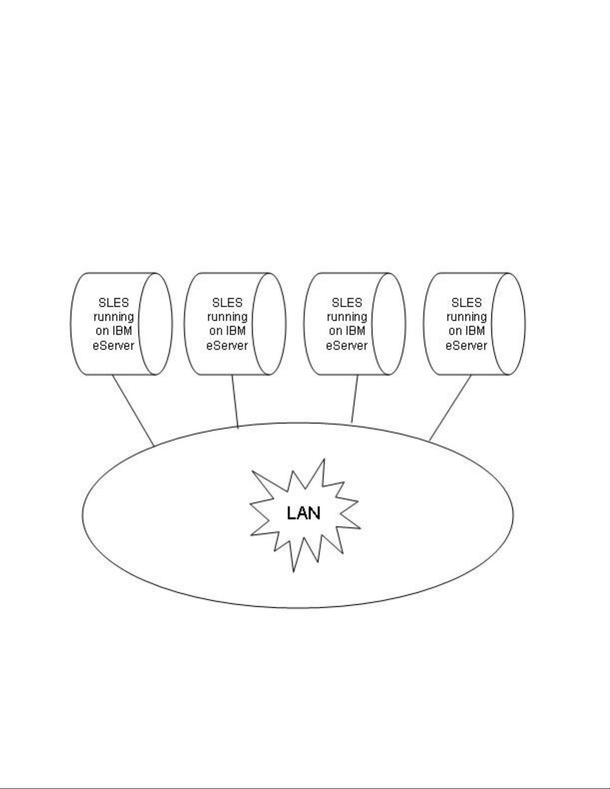
Multiple TOE systems can be connected via a physically-protected Local Area Network (LAN). The IBM
eServer line consists of Intel processor-based System x systems, POWER5™ and POWER5+™ processorbased System p systems, IBM mainframe System z systems, and AMD Opteron processor-based systems that
are intended for use as networked workstations and servers.
Figure 2-1 shows a series of interconnected TOE systems. Each TOE system is running the SLES operating
system on an eServer computer. Each computer provides the same set of local services, such as file, memory,
and process management. Each computer also provides network services, such as remote secure shells and
file transfers, to users on other computers. A user logs in to a host computer and requests services from the
local host and also from other computers within the LAN.
Figure 2-1: Series of TOE systems connected by a physically protected LAN
User programs issue network requests by sending Transmission Control Protocol (TCP) or User Datagram
Protocol (UDP) messages to another computer. Some network protocols, such as Secure Shell (ssh), can start
a shell process for the user on another computer, while others are handled by trusted server daemon processes.
2
Page 15

The TOE system provides user Identification and Authentication (I&A) mechanism by requiring each user to
log in with proper password at the local workstation, and also at any remote computer where the user can
enter commands to a shell program (for example, remote ssh sessions). Each computer enforces a coherent
Discretionary Access Control (DAC) policy, based on UNIX®-style mode bits and an optional Access
Control List (ACL) for the named objects under its control.
This chapter documents the SUSE Linux Enterprise Server and IBM eServer product histories, provides an
overview of the TOE system, and identifies the portion of the system that constitutes the TOE Security
Functions (TSF).
2.1 Product history
This section gives a brief history of the SLES and the IBM eServer series systems.
2.1.1 SUSE Linux Enterprise Server
SUSE Linux Enterprise Server is based on version 2.6 of the Linux kernel. Linux is a UNIX-like open-source
operating system originally created in 1991 by Linus Torvalds of Helsinki, Finland. SUSE was founded in
1992 by four German software engineers, and is the oldest major Linux solutions provider.
2.1.2 eServer systems
IBM eServer systems were introduced in 2000. The IBM eServer product line brings technological
innovation, application flexibility, and autonomic capabilities for managing the heterogeneous mix of servers
required to support dynamic on-demand business. It enables customers to meet their business needs by
providing unlimited scalability, support for open standards, and mission-critical qualities of service.
Following are systems in the IBM eServer product line that are included in the TOE:
• System z: Mainframe-class servers running mission-critical applications.
• System p: UNIX servers, technologically advanced POWER5 and POWER5+ processor-based
servers for commercial and technical computing applications.
• System x: Intel-based servers with high performance and outstanding availability.
• eServer 326: AMD Opteron-based servers with outstanding value in high performance computing in
both 32-bit and 64-bit environments.
• BladeCenter
®
: Intel Xeon, AMD Opteron, PowerPC, POWER5, and POWER5+ processor based
servers.
Since introducing eServers in 2000, new models with more powerful processors have been added to the
System x, System p, and System z lines. The AMD Opteron processor-based eServer 325 was added to the
eServer series in 2003; the eServer 326 is the next iteration of that model with updated components. The
AMD Opteron eServer 326 is designed for powerful scientific and technical computing. The Opteron
processor supports both 32-bit and 64-bit architectures, thus allowing easy migration to 64-bit computing.
2.2 High-level product overview
The TOE consists of SLES running on an eServer computer. The TOE system can be connected to other
systems by a protected LAN. SLES provides a multi-user, multi-processing environment, where users
interact with the operating system by issuing commands to a command interpreter, by running system
utilities, or by the users developing their own software to run in their own protected environments.
3
Page 16
The Common Criteria for Information Technology Security Evaluation [CC] and the Common Methodology
for Information Technology Security Evaluation [CEM] demand breaking the TOE into logical subsystems
that can be either (a) products, or (b) logical functions performed by the system.
The approach in this section is to break the system into structural hardware and software subsystems that
include, for example, pieces of hardware such as planars and adapters, or collections of one or more software
processes such as the base kernel and kernel modules. Chapter 4 explains the structure of the system in terms
of these architectural subsystems. Although the hardware is also described in this document, the reader should
be aware that while the hardware itself is part of the TOE environment, it is not part of the TOE.
The following subsections present a structural overview of the hardware and software that make up an
individual eServer host computer. This single-computer architecture is one of the configurations permitted
under this evaluation.
2.2.1 eServer host computer structure
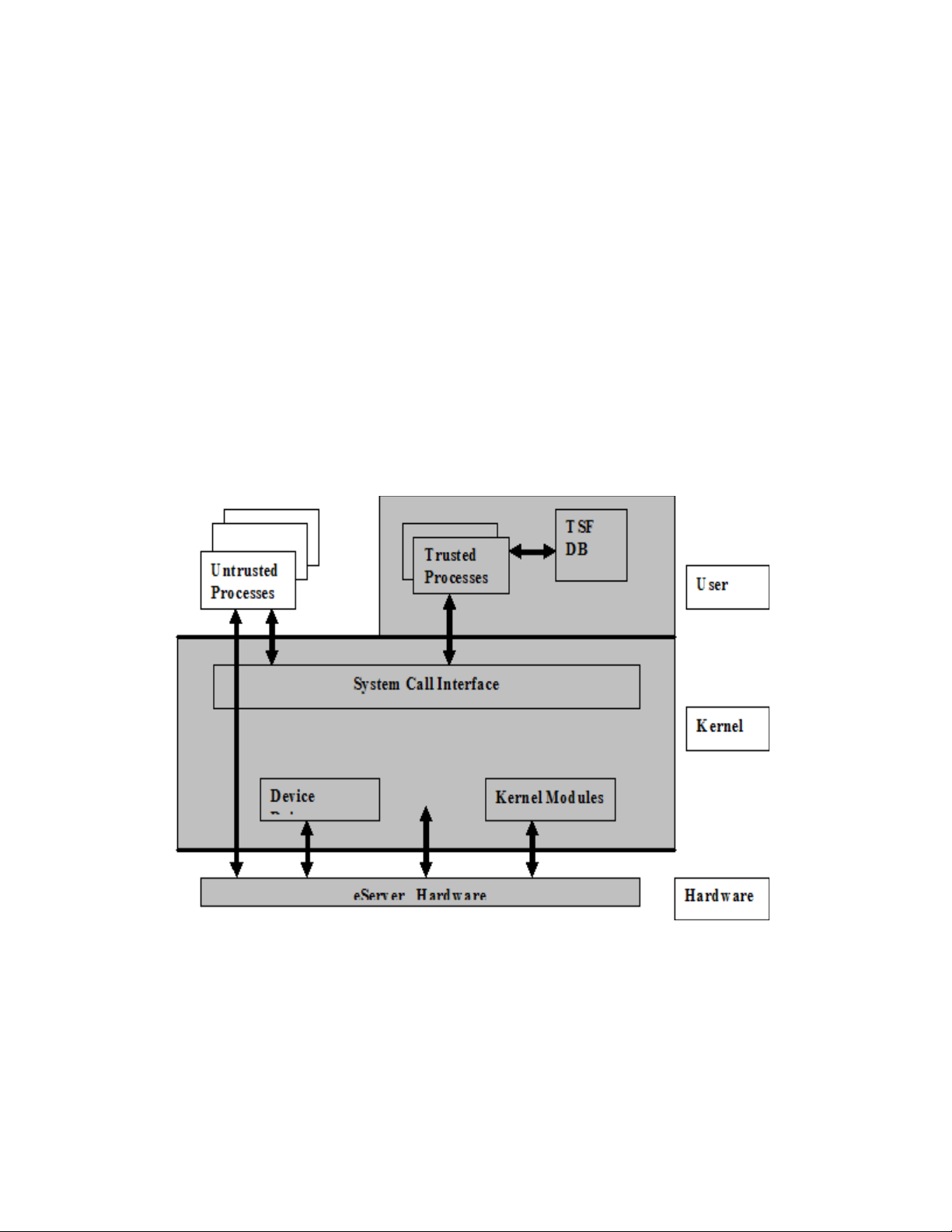
This section describes the structure of SLES for an individual eServer host computer. As shown in Figure 2-2,
the system consists of eServer hardware, the SLES kernel, trusted non-kernel processes, TSF databases, and
untrusted processes. In this figure, the TOE itself consists of Kernel Mode software, User Mode software,
and hardware. The TOE Security Functions (TSF) are shaded in gray. Details such as interactions within the
kernel, inter-process communications, and direct user access to the hardware are omitted.
Figure 2-2: Overall structure of the TOE
The planar components, including CPUs, memory, buses, on board adapters, and support circuitry; additional
adapters, including LAN and video; and, other peripherals, including storage devices, monitors, keyboards,
and front-panel hardware, constitute the hardware.
4
Page 17

The SLES kernel includes the base kernel and separately-loadable kernel modules and device drivers. (Note
that a device driver can also be a kernel module.) The kernel consists of the bootable kernel image and its
loadable modules. The kernel implements the system call interface, which provides system calls for file
management, memory management, process management, networking, and other TSF (logical subsystems)
functions addressed in the Functional Descriptions chapter of this document. The structure of the SLES kernel
is described further in the Software Architecture chapter of this paper.
Non-kernel TSF software includes programs that run with the administrative privilege, such as the sshd,
cron, atd, and vsftpd daemons. The TSF also includes the configuration files that define authorized
users, groups of users, services provided by the system, and other configuration data. Not included as TSF
are shells used by administrators, and standard utilities invoked by administrators.
The SLES system, which includes hardware, kernel-mode software, non-kernel programs, and databases,
provides a protected environment in which users and administrators run the programs, or sequences of CPU
instructions. Programs execute as processes with the identity of the users that started them (except for some
exceptions defined in this paper), and with privileges as dictated by the system security policy. Programs are
subject to the access control and accountability processes of the system.
5
Page 18

2.2.2 eServer system structure
The system is an eServer computer, which permits one user at a time to log in to the computer console.
Several virtual consoles can be mapped to a single physical console. Different users can login through
different virtual consoles simultaneously. The system can be connected to other computers via physically and
logically protected LANs. The eServer hardware and the physical LAN connecting the different systems
running SLES are not included within the evaluation boundary of this paper. External routers, bridges, and
repeaters are also not included in the evaluation boundary of this paper.
A standalone host configuration operates as a CC-evaluated system, which can be used by multiple users at a
time. Users can operate by logging in at the virtual consoles or serial terminals of a system, or by setting-up
background execution jobs. Users can request local services, such as file, memory, and process management,
by making system calls to the kernel. Even though interconnection of different systems running SLES is not
included in the evaluation boundary, the networking software is loaded. This aids in a user’s request for
network services (for example, FTP) from server processes on the same host.
Another configuration provides a useful network configuration, in which a user can log in to the console of
any of the eServer host computers, request local services at that computer, and also request network services
from any of the other computers. For example, a user can use ssh to log into one host from another, or scp
to transfer files from one host to another. The configuration extends the single LAN architecture to show that
SLES provides Internet Protocol (IP) routing from one LAN segment to another. For example, a user can log
in at the console of a host in one network segment and establish an ssh connection to a host in another
network segment. Packets on the connection travel across a LAN segment, and they are routed by a host in
that segment to a host on another LAN segment. The packets are eventually routed by the host in the second
LAN segment to a host on a third LAN segment, and from there are routed to the target host. The number of
hops from the client to the server are irrelevant to the security provided by the system, and are transparent to
the user.
The hosts that perform routing functions have statically-configured routing tables. When the hosts use other
components for routing (for example, a commercial router or switches), those components are assumed to
perform the routing functions correctly, and do not alter the data part of the packets.
If other systems are to be connected to the network, with multiple TOE systems connected via a physically
protected LAN, then they need to be configured and managed by the same authority using an appropriate
security policy not conflicting with the security policy of the TOE.
2.2.3 TOE services
Each host computer in the system is capable of providing the following types of services:
• Local services to the users who are currently logged in to the system using a local computer console,
virtual consoles, or terminal devices connected through physically protected serial lines.
• Local services to the previous users via deferred jobs; an example is the cron daemon.
• Local services to users who have accessed the local host via the network using a protocol such as
ssh, which starts a user shell on the local host.
• Network services to potentially multiple users on either the local host or on remote hosts.
Figure 2-3 illustrates the difference between local services that take place on each local host computer, versus
network services that involve client-server architecture and a network service layer protocol. For example, a
user can log in to the local host computer and make file system requests or memory management requests for
services via system calls to the kernel of the local host. All such local services take place solely on the local
host computer and are mediated solely by trusted software on that host.
6
Page 19
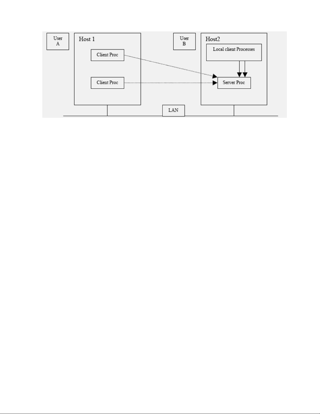
Figure 2-3: Local and network services provided by SLES
Network services, such as ssh or ftp, involve client-server architecture and a network service-layer
protocol. The client-server model splits the software that provides a service into a client portion that makes
the request, and a server portion that carries out the request, usually on a different computer. The service
protocol is the interface between the client and server. For example, User A can log in at Host 1, and then use
ssh to log in to Host 2. On Host 2, User A is logged in from a remote host.
On Host 1, when User A uses ssh to log in to Host 2, the ssh client on Host 1 makes protocol requests to an
ssh server process on Host 2. The server process mediates the request on behalf of User A, carries out the
requested service, if possible, and returns the results to the requesting client process.
Also, note that the network client and server can be on the same host system. For example, when User B uses
ssh to log in to Host 2, the user's client process opens an ssh connection to the ssh server process on Host 2.
Although this process takes place on the local host computer, it is distinguished from local services because it
involves networking protocols.
2.2.4 Security policy
A user is an authorized individual with an account. Users can use the system in one of three ways:
1. By interacting directly with the system thorough a session at a computer console (in which case the
user can use the graphical display provided as the console), or
2. By interacting directly with system through a session at a serial terminal, or
3. Through deferred execution of jobs using the cron and atd utilities.
A user must log in at the local system in order to access the protected resources of the system. Once a user is
authenticated, the user can access files or execute programs on the local computer, or make network requests
to other computers in the system.
The only subjects in the system are processes. A process consists of an address space with an execution
context. The process is confined to a computer; there is no mechanism for dispatching a process to run
remotely (across TCP/IP) on another host. Every process has a process ID (PID) that is unique on its local
host computer, but PIDs are not unique throughout the system. As an example, each host in the system has an
init process with PID 1. Section 5.2 of this document explains how a parent process creates a child by making
a clone(), fork() or a vfork() system call; the child can then call execve() to load a new program.
7
Page 20

Objects are passive repositories of data. The TOE defines three types of objects: named objects, storage
objects, and public objects. Named objects are resources, such as files and IPC objects, which can be
manipulated by multiple users using a naming convention defined at the TSF interface. A storage object is an
object that supports both read and write access by multiple non-trusted subjects. Consistent with these
definitions, all named objects are also categorized as storage objects, but not all storage objects are named
objects. A public object is an object that can be publicly read by non-trusted subjects and can be written only
by trusted subjects.
SLES enforces a DAC policy for all named objects under its control, and an object reuse policy for all storage
objects under its control. Additional access control checks are possible, if an optional kernel module is
loaded, such as AppArmor. If AppArmor is loaded, DAC policy is enforced first, and the additional access
control checks are made only if DAC would allow the access. The additional checks are non-authoritative;
that is, a DAC policy denial cannot be overridden by the additional access control checks in the kernel
module.
While the DAC policy that is enforced varies among different object classes, in all cases it is based on user
identity and on group membership associated with the user identity. To allow for enforcement of the DAC
policy, all users must be identified, and their identities must be authenticated. The TOE uses both hardware
and software protection mechanisms.
The hardware mechanisms used by SLES to provide a protected domain for its own execution include a
multistate processor, memory segment protection, and memory page protection. The TOE software relies on
these hardware mechanisms to implement TSF isolation, non-circumventability, and process address-space
separation.
A user can log in at the console, at other directly attached terminals, or through a network connection.
Authentication is based on a password entered by the user and authentication data stored in a protected file.
Users must log in to a host before they can access any named objects on that host. Some services, such as
ssh to obtain a shell prompt on another host, or ftp to transfer files between hosts in the distributed system,
require the user to re-enter authentication data to the remote host. SLES permits the user to change passwords
(subject to TOE enforced password guidelines), change identity, submit batch jobs for deferred execution, and
log out of the system. The Strength of Function Analysis [VA] shows that the probability of guessing a
password is sufficiently low given the minimum password length and maximum password lifetime.
The system architecture provides TSF self-protection and process isolation mechanisms.
2.2.5 Operation and administration
The eServer networks can be composed of one, several, or many different host computers, each of which can
be in various states of operation, such as being shut down, initializing, being in single-user mode, or online in
a secure state. Thus, administration involves the configuration of multiple computers and the interactions of
those computers, as well as the administration of users, groups, files, printers, and other resources for each
eServer system.
The TOE provides the useradd, usermod, and userdel commands to add, modify, and delete a user
account. It provides the groupadd, groupmod, and groupdel commands to add, modify, and delete a
group from the system. These commands accept options to set up or modify various parameters for accounts
and groups. The commands modify the appropriate TSF databases and provide a safer way than manual
editing to update authentication databases. Refer to the appropriate command man pages for detailed
information about how to set up and maintain users and groups.
2.2.6 TSF interfaces
The TSF interfaces include local interfaces provided by each host computer, and the network client-server
interfaces provided by pairs of host computers.
8
Page 21

The local TSF interfaces provided by an individual host computer include:
• Files that are part of the TSF database that define the configuration parameters used by the security
functions.
• System calls made by trusted and untrusted programs to the privileged kernel-mode software. As
described separately in this document, system calls are exported by the base SLES kernel and by
kernel modules.
• Interfaces to trusted processes and trusted programs
• Interfaces to the SLES kernel through the /proc and the /sys pseudo file systems
External TSF interfaces provided by pairs of host computer include SSH v2 and SSL v3.
For more detailed information about these interfaces, refer to:
• SSH v2 Proposed Standard RFC 4819 Secure Shell Public Key Subsystem
http://www.ietf.org/rfc/rfc4819.txt
• SSLv3 Draft http://wp.netscape.com/eng/ssl3/draft302.txt
• RFC 3268 Advanced Encryption Standard (AES) Ciphersuites for Transport Layer Security (TLS)
http://www.ietf.org/rfc/rfc3268.txt
The following are interfaces that are not viewed as TSF interfaces:
• Interfaces between non-TSF processes and the underlying hardware. Typically, user processes do not
interface directly with the hardware; exceptions are processor and graphics hardware. User processes
interact with the processor by executing CPU instructions, reading and modifying CPU registers, and
modifying the contents of physical memory assigned to the process. User processes interact with
graphics hardware by modifying the contents of registers and memory on the graphics adapter.
Unprivileged processor instructions are externally visible interfaces. However, the unprivileged
processor instructions do not implement any security functionality, and the processor restricts these
instructions to the bounds defined by the processor. Therefore, this interface is not considered as part
of the TSF.
• Interfaces between different parts of the TSF that are invisible to normal users (for example, between
subroutines within the kernel) are not considered to be TSF interfaces. This is because the interface is
internal to the trusted part of the TOE and cannot be invoked outside of those parts. Those interfaces
are therefore not part of the functional specification, but are explained in this HLD.
• The firmware (PR/SM
TM
, z/VMTM, P5-LPAR), while part of the TOE, are not considered as providing
TSF interfaces because they do not allow direct unprivileged operations to them.
• System z processor exceptions reflected to the firmware, including z/VM, PR/SM, and LPAR, are not
considered to be TSF interfaces. They are not relevant to security because they provide access to the
z/VM kernel, which does not implement any security functionality.
• The System z z/VM DIAGNOSE code interface is not considered a TSF interface because it is not
accessible by unprivileged processes in the problem state, and does not provide any security
functionality.
TSF interfaces include any interface that is possible between untrusted software and the TSF.
2.3 Approach to TSF identification
This section summarizes the approach to identification of the TSF.
As stated in Section 2.2.6, while the hardware and firmware (z/VM, PR/SM, LPAR) are part of the TOE, they
are not considered as providing TSF interfaces. The SLES operating system, on the other hand, does provide
TSF interfaces.
9
Page 22

The SLES operating system is distributed as a collection of packages. A package can include programs,
configuration data, and documentation for the package. Analysis is performed at the file level, except where a
particular package can be treated collectively. A file is included in the TSF for one or more of the following
reasons:
• It contains code, such as the kernel, kernel module, and device drivers, that runs in a privileged
hardware state.
• It enforces the security policy of the system.
• It allows setuid or setgid to a privileged user (for example, root) or group.
• It started as a privileged daemon; an example is one started by /etc/init.d.
• It is software that must function correctly to support the system security mechanisms.
• It is required for system administration.
• It consists of TSF data or configuration files.
• It consists of libraries linked to TSF programs.
There is a distinction between non-TSF user-mode software that can be loaded and run on the system, and
software that must be excluded from the system. The following methods are used to ensure that excluded
software cannot be used to violate the security policies of the system:
• The installation software will not install any device drivers except those required for the installed
hardware. Consequently, excluded device drivers will not be installed even if they are on the
installation media.
• The installation software may change the configuration (for example, mode bits) so that a program
cannot violate the security policy.
10
Page 23

11
Page 24

3 Hardware architecture
The TOE includes the IBM System x, System p, System z, and eServer 326. This section describes the
hardware architecture of these eServer systems. For more detailed information about Linux support and
resources for the entire eServer line, refer to http://www.ibm.com/systems/browse/linux.
3.1 System x
IBM System x systems are Intel processor-based servers with X-architecture technology enhancements for
reliability, performance, and manageability. X-architecture is based on technologies derived from the IBM
ESTM-, RSTM-, and ASTM-series servers.
3.1.1 System x hardware overview
The IBM System x servers offer a range of systems, from entry-level to enterprise class. The high-end
systems offer support for gigabytes of memory, large RAID configurations of SCSI and fiber channel disks,
and options for high-speed networking. IBM System x servers are equipped with a real-time hardware clock.
The clock is powered by a small battery and continues to tick even when the system is switched off. The realtime clock maintains reliable time for the system. For the specification of each of the System x servers, refer
to the system x hardware Web site at http://www.ibm.com/systems/x/.
3.1.2 System x hardware architecture
The IBM System x servers are powered by Intel Xeon® and Xeon MP processors. For detailed specification
information for each of these processors, refer to the Intel processor spec-finder Web site at
http://processorfinder.intel.com/scripts/default.asp.
The Intel Xeon processor is mainly based on EM64 technology, which has the following three operating
modes:
• 32-bit legacy mode: In this mode, both AMD64 and EM64T processors will act just like any other
IA32 compatible processor. One can install this 32-bit operating system and run 32-bit applications
on such a system, but it fails to make use of new features such as flat memory addressing above 4 GB
or the additional general Purpose Registers (GPRs). 32-bit applications will run just as fast as they
would on any current 32-bit processor.
• Compatibility mode: This is an intermediate mode of the full 64-bit mode described next. In this
mode one has to install a 64-bit operating system and 64-bit drivers. If a 64-bit operating system and
drivers are installed, Xeon processors will be enabled to support a 64-bit operating system with both
32-bit applications or 64-bit applications. Hence this mode has the ability to run a 64-bit operating
system while still being able to run unmodified 32-bit applications. Each 32-bit application will still
be limited to a maximum of 4 GB of physical memory. However, the 4 GB limit is now imposed on
a per-process level, not at a system-wide level.
• Full 64-bit mode: This mode is referred as IA-32e mode. This mode is operative when a 64-bit
operating system and 64-bit application are used. In the full 64-bit operating mode, an application
can have a virtual address space of up to 40 bits, which equates to 1 TB of addressable memory. The
amount of physical memory will be determined by how many Dual In-line Memory Module (DIMM)
slots the server has, and the maximum DIMM capacity supported and available at the time.
12
Page 25

In this mode, applications may access:
• 64-bit flat linear addressing
• 8 new general-purpose registers (GPRs)
• 8 new registers for streaming Single Instruction/Multiple Data (SIMD) extensions (SSE, SSE2 and
SSE3)
• 64-bit-wide GPRs and instruction pointers
• uniform byte-register addressing
• fast interrupt-prioritization mechanism
• a new instruction-pointer relative-addressing mode.
For architectural details about all System x models, and for detailed information about individual components
such as memory, cache, and chipset, refer to the “Accessories & Upgrades” section at
http://www.ibm.com/systems/x/
USB (except keyboard and mouse), PCMCIA, and IEEE 1394 (Firewire) devices are not supported in the
evaluated configuration.
3.2 System p
The IBM System p systems are PowerPC, POWER5 and POWER5+ processor-based systems that provide
high availability, scalability, and powerful 64-bit computing performance.
For more detailed information about the System p hardware, refer to the System p hardware website at
http://www.ibm.com/systems/p/.
3.2.1 System p hardware overview
The IBM System p servers offer a range of systems, from entry level to enterprise class. The high-end
systems offer support for gigabytes of memory, large RAID configurations of SCSI and fiber channel disks,
and options for high-speed networking. The IBM System p servers are equipped with a real-time hardware
clock. The clock is powered by a small battery, and continues to tick even when the system is switched off.
The real-time clock maintains reliable time for the system. For the specification of each of the System p
servers, refer to the corresponding data sheets on the System p literature website:
http://www.ibm.com/systems/p/library/index_lit.html.
For a detailed look at various peripherals such as storage devices, communications interfaces, storage
interfaces, and display devices supported on these System p models, refer to the Linux on POWER website.
http://www.ibm.com/systems/linux/power/.
3.2.2 System p hardware architecture
The IBM System p servers are powered by PowerPC™, POWER5™ and POWER5+™ processors. For
detailed specification information for each of these processors, refer to the PowerPC processor documentation
at http://www.ibm.com/chips/power/powerpc/ and POWER documentation at
http://www.ibm.com/chips/power/aboutpower/.
For architectural details about all System p models, and for detailed information about individual components
such as memory, cache, and chipset, refer to the IBM System p technical documentation at
http://publib16.boulder.ibm.com/pseries/en_US/infocenter/base/hardware.htm or
http://www.ibm.com/servers/eserver/pseries/library/.
13
Page 26

USB (except keyboard and mouse), PCMCIA, and IEEE 1394 (Firewire) devices are not supported in the
evaluated configuration.
3.3 System z
The IBM System z is designed and optimized for high-performance data and transaction serving
requirements. On a System z system, Linux can run on native hardware, in a logical partition, or as a guest of
the z/VM® operating system. SLES runs on System z as a guest of the z/VM Operating System.
For more detailed information about the System z hardware, refer to the System z hardware website at
http://www.ibm.com/systems/z/.
3.3.1 System z hardware overview
The System z hardware runs z/Architecture™ and the S/390™ Enterprise Server Architecture (ESA)
software. The IBM System z server is equipped with a real-time hardware clock. The clock is powered by a
small battery, and continues to tick even when the system is switched off. The real-time clock maintains
reliable time for the system. For a more detailed overview of the System z hardware models, or detailed
information about specific models, refer to the http://www.ibm.com/systems/z/hardware/ site.
3.3.2 System z hardware architecture
The System z servers are powered by IBM’s multi-chip module (MCM), which contains up to 20 processing
units (PUs). These processing units contain the z/Architecture logic. There are three modes in which Linux
can be run on a System z server: native hardware mode, logical partition mode, and z/VM guest mode. The
following paragraphs describe these modes.
• Native hardware mode: In native hardware mode, Linux can run on the entire machine without any
other operating system. Linux controls all I/O devices and needs support for their corresponding
device drivers.
• Logical partition mode: A System z system can be logically partitioned into a maximum of 30
separate Logical Partitions (LPARs). A single System z server can then host the z/OS operating
system in one partition, and Linux in another. Devices can be dedicated to a particular logical
partition, or they can be shared among several logical partitions. The Linux operating system controls
devices allocated to its partition, and thus needs support for their corresponding device drivers.
• z/VM guest mode: Linux can run in a virtual machine using the z/VM operating system as a
hypervisor. The hypervisor provides virtualization of CPU processors, I/O subsystems, and memory.
In this mode, hundreds of Linux instances can run on a single System z system. SLES runs on
System z in the z/VM guest mode. Virtualization of devices in the z/VM guest mode allows SLES to
operate with generic devices. The z/VM maps these generic devices to actual devices.
Figure 3-1 from the Linux Handbook [LH] illustrates z/VM concepts:
14
Page 27
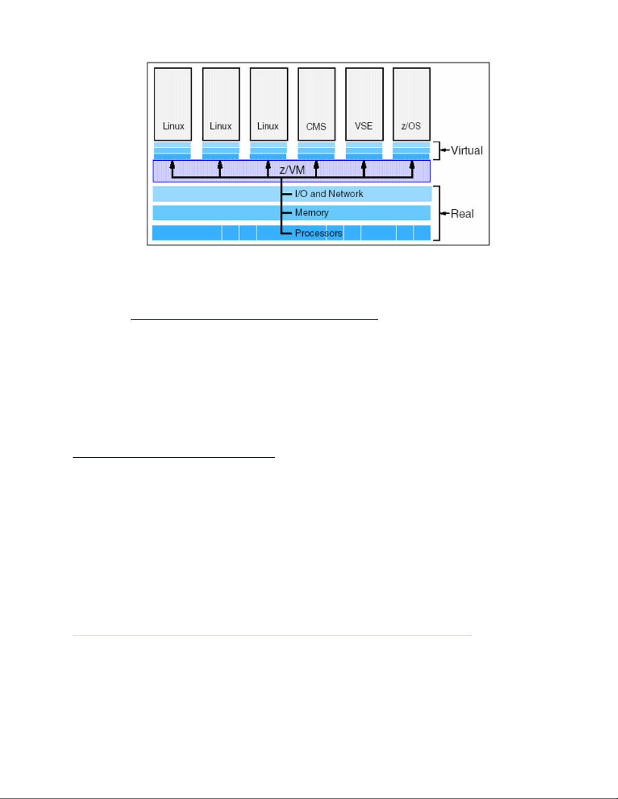
Figure 3-1: z/VM as hypervisor
For more details about z/Architecture, refer to the z/Architecture document z/Architecture Principles of
Operation at http://publibz.boulder.ibm.com/epubs/pdf/dz9zr002.pdf.
USB (except keyboard and mouse), PCMCIA, and IEEE 1394 (Firewire) devices are not supported in the
evaluated configuration.
3.4 eServer 326
The IBM eServer 326 systems are AMD Opteron processor-based systems that provide high performance
computing in both 32-bit and 64-bit environments. The eServer 326 significantly improves on existing 32-bit
applications, and excels at 64-bit computing in performance, allowing for easy migration to 64-bit computing.
For more detailed information about eServer 326 hardware, refer to the eServer 326 hardware Web site at
http://www.ibm.com/servers/eserver/opteron/.
3.4.1 eServer 326 hardware overview
The IBM eServer 326 systems offer support for up to two AMD Opteron processors, up to twelve GB of
memory, hot-swap SCSI or IDE disk drives, RAID-1 mirroring, and options for high-speed networking. The
IBM eServer 326 server is equipped with a real-time hardware clock. The clock is powered by a small battery
and continues to tick even when the system is switched off. The real-time clock maintains reliable time for
the system.
3.4.2 eServer 326 hardware architecture
The IBM eServer 326 systems are powered by AMD Opteron processors. For detailed specifications of the
Opteron processor, refer to the processor documentation at
http://www.amd.com/us-en/Processors/TechnicalResources/0,,30_182_739_9003,00.html.
The Opteron is based on the AMD x86-64 architecture. The AMD x86-64 architecture is an extension of the
x86 architecture, extending full support for 16-bit, 32-bit, and 64-bit applications running concurrently.
The x86-64 architecture adds a mode called the long mode. The long mode is activated by a global control bit
called Long Mode Active (LMA). When LMA is zero, the processor operates as a standard x86 processor
and is compatible with the existing 32-bit SLES operating system and applications. When LMA is one, 64-bit
15
Page 28
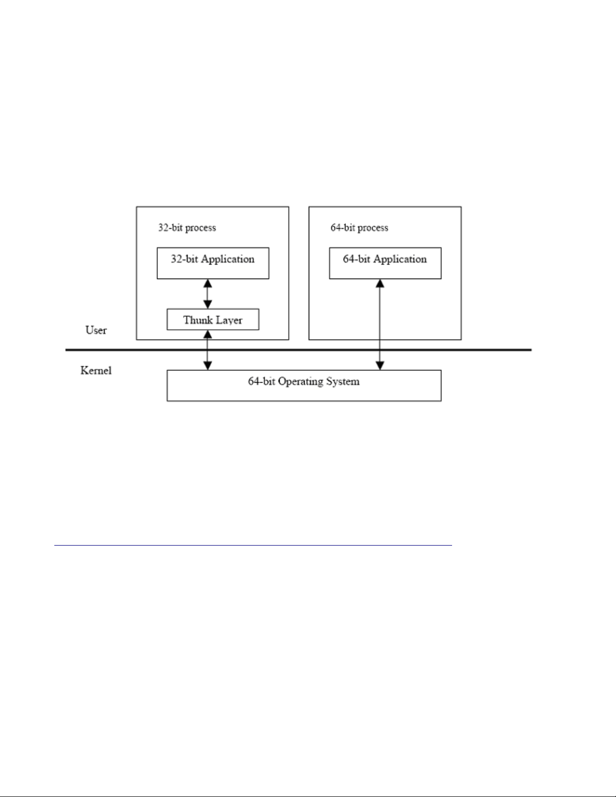
processor extensions are activated, allowing the processor to operate in one of two sub-modes of LMA.
These are the 64-bit mode and the compatibility mode.
• 64-bit mode: In 64-bit mode, the processor supports 64-bit virtual addresses, a 64-bit instruction
pointer, 64-bit general-purpose registers, and eight additional general-purpose registers, for a total of
16 general-purpose registers.
• Compatibility mode: Compatibility mode allows the operating system to implement binary
compatibility with existing 32-bit x86 applications. These legacy applications can run without
recompilation. This coexistence of 32-bit legacy applications and 64-bit applications is implemented
with a compatibility thunk layer.
Figure 3-2: AMD x86-64 architecture in compatibility mode
The thunk layer is a library provided by the operating system. The library resides in a 32-bit process created
by the 64-bit operating system to run 32-bit applications. A 32-bit application, transparent to the user, is
dynamically linked to the thunk layer and implements 32-bit system calls. The thunk layer translates system
call parameters, calls the 64-bit kernel, and translates results returned by the kernel appropriately and
transparently for a 32-bit application.
For detailed information about the x86-64 architecture, refer to the AMD Opteron technical documentation at
http://www.amd.com/us-en/Processors/TechnicalResources/0,,30_182_739_7044,00.html.
USB (except keyboard and mouse), PCMCIA, and IEEE 1394 (Firewire) devices are not supported in the
evaluated configuration.
16
Page 29

17
Page 30

4 Software architecture
This chapter summarizes the software structure and design of the SLES system and provides references to
detailed design documentation.
The following subsections describe the TOE Security Functions (TSF) software and the TSF databases for the
SLES system. The descriptions are organized according to the structure of the system and describe the SLES
kernel that controls access to shared resources from trusted (administrator) and untrusted (user) processes.
This chapter provides a detailed look at the architectural pieces, or subsystems, that make up the kernel and
the non-kernel TSF. This chapter also summarizes the databases that are used by the TSF.
The Functional Description chapter that follows this chapter describes the functions performed by the SLES
logical subsystems. These logical subsystems generally correspond to the architectural subsystems described
in this chapter. The two topics were separated into different chapters in order to emphasize that the material
in the Functional Descriptions chapter describes how the system performs certain key security-relevant
functions. The material in this chapter provides the foundation information for the descriptions in the
Functional Description chapter.
4.1 Hardware and software privilege
This section describes the terms hardware privilege and software privilege as they relate to the SLES
operating system. These two types of privileges are critical for the SLES system to provide TSF selfprotection. This section does not enumerate the privileged and unprivileged programs. Rather, the TSF
Software Structure identifies the privileged software as part of the description of the structure of the system.
4.1.1 Hardware privilege
The eServer systems are powered by different types of processors. Each of these processors provides a notion
of user mode execution and supervisor, or kernel, mode execution. The following briefly describes how these
user- and kernel-execution modes are provided by the System x, System p, System z, and eServer 326
systems.
4.1.1.1 Privilege level
This section describes the concept of privilege levels by using Intel-based processors as an example. The
concept of privilege is implemented by assigning a value of 0 to 3 to key objects recognized by the processor.
This value is called the privilege level. The following processor-recognized objects contain privilege levels:
• Descriptors contain a field called the descriptor privilege level (DPL).
• Selectors contain a field called the requestor’s privilege level (RPL). The RPL is intended to
represent the privilege level of the procedure that originates the selector.
• An internal processor register records the current privilege level (CPL). Normally the CPL is equal
to the DPL of the segment the processor is currently executing. The CPL changes as control is
transferred to segments with differing DPLs.
Figure 4-1 shows how these levels of privilege can be interpreted as layers of protection. The center is for the
segments containing the most critical software, usually the kernel of the operating system. Outer layers are for
the segments of less critical software.
18
Page 31
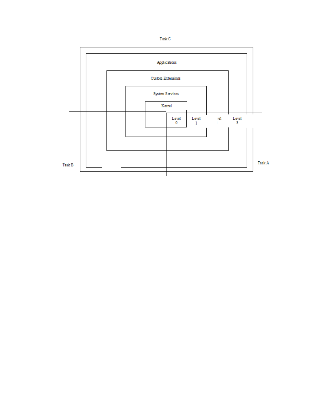
Figure 4-1: Levels of Privilege
System x: The System x servers are powered by Intel processors. Intel processors provide four execution
modes, identified with processor privilege levels 0 through 3. The highest privilege level execution mode
corresponds to processor privilege level 0; the lowest privilege level execution mode corresponds to processor
privilege level 3. The SLES kernel, as with most other UNIX-variant kernels, utilizes only two of these
execution modes. The highest, with processor privilege level of 0, corresponds to the kernel mode; the
lowest, with processor privilege of 3, corresponds to the user mode.
System p: The System p servers are powered by PowerPC, POWER5 and POWER5+ processors. These
processors provide three execution modes, identified by the PR bit (bit 49) and the HV bit (bit 3) of the
Machine State Register of the processor. Values of 0 for both PR and HV bits indicate a hypervisor execution
mode. An HV bit value of 1, and a PR bit value of 0, indicate a supervisor, or kernel, execution mode. An
HV bit value of 1 and a PR bit value of 1 indicate a user execution mode.
System z: The System z systems also provide two execution modes identified by the Problem State bit (bit
15) of the processor’s Program Status Word (PSW). A value of 0 indicates a supervisor, or kernel, execution
mode, and the value of 1 indicates a problem state, or user, execution mode.
eServer 326: The eServer 326 servers are powered by AMD Opteron processors. These processors provide
four execution modes identified with processor privilege levels 0 through 3. The highest privilege level
execution mode corresponds to processor privilege level 0; the lowest privilege level execution mode
corresponds to processor privilege level 3. The SLES kernel, as with most other UNIX-variant kernels, only
utilizes two of these execution modes. The highest, with processor privilege level of 0, corresponds to the
kernel mode; the lowest, with processor privilege of 3, corresponds to the user mode.
User and kernel modes, which are offered by all of the eServer systems, implement hardware privilege as
follows:
• When the processor is in kernel mode, the program has hardware privilege because it can access and
modify any addressable resources, such as memory, page tables, I/O address space, and memory
management registers. This is not possible in the user mode.
19
Page 32

• When the processor is in kernel mode, the program has hardware privilege because it can execute
certain privileged instructions that are not available in user mode.
Thus, any code that runs in kernel mode executes with hardware privileges. Software that runs with hardware
privileges includes:
• The base SLES kernel. This constitutes a large portion of software that performs memory
management file I/O and process management.
• Separately loaded kernel modules, such as ext3 device driver modules. A module is an object file
whose code can be linked to, and unlinked from, the kernel at runtime. The module code is executed
in kernel mode on behalf of the current process, like any other statically-linked kernel function.
All other software on the system normally runs in user mode, without hardware privileges, including user
processes such as shells, networking client software, and editors. User-mode processes run with hardware
privileges when they invoke a system call. The execution of the system call switches the mode from user to
kernel mode, and continues operation at a designated address within the kernel where the code of the system
call is located.
4.1.2 Software privilege
Software privilege is implemented in the SLES software and is based on the user ID of the process. Processes
with user ID of 0 are allowed to bypass the system’s access control policies. Examples of programs running
with software privilege are:
Programs that are run by the system, such as the cron and at daemon.
Programs that are run by trusted administrators to perform system administration.
Programs that run with privileged identity by executing setuid programs.
The SLES kernel also has a framework for providing software privilege through capabilities. These
capabilities, which are based on the POSIX.1e draft, allow breakup of the kernel software privilege associated
with user ID zero into a set of discrete privileges based on the operation being attempted. For example, if a
process is trying to create a device special file by invoking the mknod() system call, instead of checking to
ensure that the user ID is zero, the kernel checks to ensure that the process is “capable” of creating device
special files. In the absence of special kernel modules that define and use capabilities, as is the case with the
TOE, capability checks revert back to granting kernel software privilege based on the user ID of the process.
All software that runs with hardware privileges or software privileges and that implements security enforcing
functions is part of the TSF. All other programs are either unprivileged software that run with the identity of
the user that invoked the program, or software that executes with privileges but does not implement any
security functions. In a properly administered system, unprivileged software is subject to the system’s security
policies and does not have any means of bypassing the enforcement mechanisms. This unprivileged software
need not be trusted in any way and is thus referred to as untrusted software. Trusted processes that do not
implement any security function need to be protected from unauthorized tampering using the security
functions of the SLES. They need to be trusted to not perform any function that violates the security policy of
the SLES.
SLES implements an access control model that enforces Discretionary Access Control and optional additional
access control checks implemented in a kernel module known as an Linux Security Module (LSM), such as
AppArmor. Discretionary Access Control (DAC) is applied first, and the optional additional checks are
applied if and only if the DAC check grants access. AppArmor, if loaded, can only further restrict access,
never grant additional access. If access is granted by DAC policy and the AppArmor LSM is loaded, the
AppArmor LSM goes through a multi-step process, described in Section 5.8, to determine if access should be
allowed.
20
Page 33

4.1.2.1 DAC
The DAC model allows the owner of the object to decide who can access that object, and in what manner.
Like any other access control model, DAC implementation can be explained by which subjects and objects
are under the control of the model, security attributes used by the model, access control and attribute
transition rules, and the override (software privilege) mechanism to bypass those rules.
4.1.2.1.1 Subjects and objects
Subjects in SLES are regular processes and kernel threads. They are both represented by the task_struct
structure. Kernel threads run only in the kernel mode, and are not constrained by the DAC policy. All named
objects such as regular files, character and block files, directories, sockets, and IPC objects are under the
control of the DAC policy.
4.1.2.1.2 Attributes
Subject attributes used to enforce DAC policy are the process UID, GID, supplementary groups, and process
capabilities. These attributes are stored in the task_structure of the process, and are affected by the
system calls as described in Section 5.2. Object attributes used to enforce DAC policy are owner, group
owner, permission bits, and POSIX.1e Access Control Lists (ACLs). These attributes are stored in-core and,
for appropriate disk-based file systems, in the on-disk inode.
4.1.2.1.3 Access control rules
DAC access control rules specify how a certain process with appropriate DAC security attributes can access
an object with a set of DAC security attributes. In addition, DAC access control rules also specify how
subject and object security attributes transition to new values and under what conditions. DAC access control
lists are described in detail in Section 5.1.5.
4.1.2.1.4 Software privilege
Software privilege for DAC policy is based on the user ID of the process. At any time, each process has an
effective user ID, an effective group ID, and a set of supplementary group IDs. These IDs determine the
privileges of the process. A process with a user ID of 0 is a privileged process, with capabilities of bypassing
the access control policies of the system. The user name root is commonly associated with user ID 0, but
there can be other users with this ID.
Additionally, the SLES kernel has a framework for providing software privilege for DAC policy through
capabilities. These capabilities, which are based on the POSIX.1e draft, allow breakup of the kernel software
privilege associated with user ID zero into a set of discrete privileges based on the operation being attempted.
For example, if a process is trying to create a device special file by invoking the mknod() system call, then
instead of checking to ensure that the user ID is zero, the kernel checks to ensure that the process is capable of
creating device special files. In the absence of special kernel modules that define and use capabilities, as is
the case with the TOE, capability checks revert back to granting kernel software privilege based on the user
ID of the process.
4.1.2.2 AppArmor
With AppArmor, it is the system security policy/administrator, unlike the owner in DAC, that controls which
files subjects should be allowed to access. AppArmor is implemented as a Linux Security Module (LSM) and
is an optionally loaded component of SLES. AppArmor is not required to enforce the security functionality
required by the Controlled Access Protection Profile and can only add additional restrictions.
21
Page 34
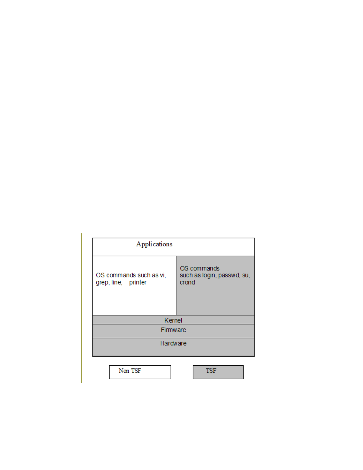
4.1.2.3 Programs with software privilege
Examples of programs running with software privilege are:
• Programs that are run by the system, such as the cron and init daemons.
• Programs that are run by trusted administrators to perform system administration.
• Programs that run with privileged identity by executing setuid programs.
All software that runs with hardware privileges or software privileges, and that implements security enforcing
functions, is part of the TOE Security Functions (TSF). All other programs are either unprivileged programs
that run with the identity of the user that invoked the program, or software that executes with privileges but
does not implement any security functions.
In a properly administered system, unprivileged software is subject to the security policies of the system and
does not have any means of bypassing the enforcement mechanisms. This unprivileged software need not be
trusted in any way, and is thus referred to as untrusted software. Trusted processes that do not implement any
security function need to be protected from unauthorized tampering using the security functions of the SLES.
They need to be trusted to not perform any function that violates the security policy of the SLES.
4.2 TOE Security Functions software structure
This section describes the structure of the SLES software that constitutes the TOE Security Functions (TSF).
The SLES system is a multi-user operating system, with the kernel running in a privileged hardware mode,
and the user processes running in user mode. The TSF includes both the kernel software and certain trusted
non-kernel processes.
Figure 4-2 depicts the TSF and non-TSF portions of software. Subsequent sections provide more detailed
descriptions of the kernel and non-kernel TSF architectural subsystems.
Figure 4-2: TSF and non-TSF software
22
Page 35

The concept of breaking the TOE product into logical subsystems is described in the Common Criteria.
These logical subsystems are the building blocks of the TOE, and are described in the Functional Descriptions
chapter of this paper. They include logical subsystems and trusted processes that implement security
functions. A logical subsystem can implement or support one or more functional components. For example,
the File and I/O subsystem is partly implemented by functions of the Virtual Memory Manager.
4.2.1 Kernel TSF software
The kernel is the core of the operating system. It interacts directly with the hardware, providing common
services to programs, and prevents programs from directly accessing hardware-dependent functions. Services
provided by the kernel include the following:
• Control of the execution of processes by allowing their creation, termination or suspension, and
communication. These include:
• Fair scheduling of processes for execution on the CPU.
• Share of processes in the CPU in a time-shared manner.
• CPU execution of a process.
• Kernel suspension when its time quantum elapses.
• Kernel schedule of another process to execute.
• Later kernel rescheduling of the suspended process.
• Allocation of the main memory for an executing process. These include:
• Kernel allowance of processes to share portions of their address space under certain
conditions, but protection of the private address space of a process from outside tampering.
• If the system runs low on free memory, the kernel frees memory by writing a process
temporarily to secondary memory, or a swap device.
• Coordination with the machine hardware to set up a virtual-to-physical address that maps the
compiler-generated addresses to their physical addresses.
• File system maintenance. These include:
• Allocation of secondary memory for efficient storage and retrieval of user data.
• Allocation of secondary storage for user files.
• Reclamation of unused storage.
• Structure of the file system in a well-understood manner.
• Protection of user files from illegal access.
• Allowance of processes’ controlled access to peripheral devices such as terminals, tape drives, disk
drives, and network devices.
• Mediation of access between subjects and objects, allowing controlled access based on DAC and
(optionally) AppArmor policy.
The SLES kernel is a fully preemptible kernel. In non-preemptive kernels, kernel code runs until completion.
That is, the scheduler is not capable of rescheduling a task while it is in the kernel. Moreover, the kernel code
is scheduled cooperatively, not preemptively, and it runs until it finishes and returns to user-space, or
explicitly blocks. In preemptive kernels, it is possible to preempt a task at any point, so long as the kernel is
in a state in which it is safe to reschedule.
23
Page 36

4.2.1.1 Logical components
The kernel consists of logical subsystems that provide different functionalities. Even though the kernel is a
single executable program, the various services it provides can be broken into logical components. These
components interact to provide specific functions.
Figure 4-3 schematically describes logical kernel subsystems, their interactions with each other, and with the
system call interface available from user space.
SELinux
Figure 4-3: Logical kernel subsystems and their interactions
The kernel consists of the following logical subsystems:
• File and I/O subsystem: This subsystem implements functions related to file system objects.
Implemented functions include those that allow a process to create, maintain, interact, and delete filesystem objects. These objects include regular files, directories, symbolic links, hard links, devicespecial files, named pipes, and sockets.
• Process subsystem: This subsystem implements functions related to process and thread management.
Implemented functions include those that allow the creation, scheduling, execution, and deletion of
process and thread subjects.
• Memory subsystem: This subsystem implements functions related to the management of memory
resources of a system. Implemented functions include those that create and manage virtual memory,
including management of page tables and paging algorithms.
• Networking subsystem: This subsystem implements UNIX and Internet domain sockets, as well as
algorithms for scheduling network packets.
• IPC subsystem: This subsystem implements functions related to IPC mechanisms. Implemented
functions include those that facilitate controlled sharing of information between processes, allowing
them to share data and synchronize their execution in order to interact with a common resource.
• Kernel modules subsystem: This subsystem implements an infrastructure to support loadable
modules. Implemented functions include those that load, initialize, and unload kernel modules.
• Device driver subsystem: This subsystem implements support for various hardware and software
devices through a common, device-independent interface.
24
Page 37

• Audit subsystem: This subsystem implements functions related to recording of security-critical
events on the system. Implemented functions include those that trap each system call to record
security critical events and those that implement the collection and recording of audit data.
4.2.1.2 Execution components
The execution components of the kernel can be divided into three components: base kernel, kernel threads,
and kernel modules depending on their execution perspective.
Figure 4-4: Kernel execution components
4.2.1.2.1 Base kernel
The base kernel includes the code that is executed to provide a service, such as servicing a user’s system call
invocation, or servicing an interrupt or exception event. A majority of the compiled kernel code falls under
this category.
4.2.1.2.2 Kernel threads
In order to perform certain routine tasks such as flushing disk caches, reclaiming memory by swapping out
unused page frames, the kernel creates internal processes, or threads.
Threads are scheduled just like regular processes, but they do not have context in user mode. Kernel threads
execute specific C kernel functions. Kernel threads reside in kernel space, and only run in the kernel mode.
Following are some of the kernel threads:
• keventd is a process context bottom-half handler that executes tasks created by interrupt handlers,
which are queued in the scheduler task queue.
• kapmd is a special idle task that handles the events related to Advanced Power Management.
• kswapd is a kernel swap daemon responsible for reclaiming pages when memory is running low.
The physical page allocator awakens it when the number of free pages for a memory zone falls below
a specific threshold.
• pdflush is a kernel thread that periodically flushes “dirty” buffers to disk based on a timer.
Multiple pdflush threads may run up to the maximum tunable by
/proc/sys/vm/nr_pdflush_threads.
• kjournald is a process that manages the logging device journal, periodically commits the current
state of the file system to disk, and reclaims space in the log by flushing buffers to disk.
• Kernel threads are created with a call to kernel_thread(), and users can list them with the ps
axu command. The command shows the kernel threads in square brackets, and can be recognized by
their virtual memory size (VSZ) of 0; an example is [kjournald].
25
Page 38

4.2.1.2.3 Kernel modules and device drivers
Kernel modules are pieces of code that can be loaded and unloaded into and out of the kernel upon demand.
They extend the functionality of the kernel without the need to reboot the system. Once loaded, the kernel
module object code can access other kernel code and data in the same manner as statically-linked kernel
object code.
A device driver is a special type of kernel module that allows the kernel to access the hardware connected to
the system. These devices can be a hard disk, monitor, or network interface. The driver interacts with the
remaining part of the kernel through a specific interface, which allows the kernel to deal with all devices in a
uniform way, independently of their underlying implementations.
4.2.2 Non-kernel TSF software
The non-kernel TSF software consists of trusted programs that are used to implement security functions. Note
that shared libraries, including PAM modules in some cases, are used by trusted programs. The trusted
commands can be grouped as follows.
• Daemon processes that do not directly run on behalf of a user, but are started at system startup or
upon demand of a system administrator. Daemon processes are responsible for setting the
appropriate user identity when performing a service on behalf of a user. Following are the daemon
processes that provide TSF functionality.
• The atd daemon is the server that reads at jobs submitted by all users and performs tasks
specified in them on behalf of the user. atd is started by the init program during system
initialization.
• The auditd daemon reads audit records from the kernel buffer through the audit device and
writes them to disk in the form of audit logs.
• The cron daemon is the daemon that reads the crontab files for all users and performs
tasks specified in the crontab files on behalf of the user. The init program starts the cron
daemon during system initialization. The crontab file and cron daemon are the clientserver pair that allow the execution of commands on a recurring basis at a specified time.
• The init program is the userspace process that is ancestor to all other userspace processes. It
starts processes as specified in the /etc/inittab file.
• The sshd daemon is the program for secure shell. The ssh command and sshd daemon are
the client-server pair that allow authorized users to log in from remote systems using secure
encrypted communications.
• The vsftpd daemon is the Very Secure File Transfer Protocol daemon that allows authorized
users to transfer files to and from remote systems.
• The xinetd daemon accepts incoming network connections and dispatches the appropriate
child daemon to service each connection request.
• Following are programs that are executed by an unprivileged user and need access to certain protected
databases to complete their work.
• The at program is the program used by all users to submit tasks to be performed at a later
time.
• The atrm program removes jobs already queued for execution. atrm deletes jobs, whose job
numbers are passed to the command line as arguments.
26
• The chage command allows the system administrator to change the user password expiry
information. Refer to the chage man page for more detailed information.
Page 39

• The crontab program is the program used to install, deinstall, or list the tables used to drive
the cron daemon. Users can have their own crontab files that set up the time and
frequency of execution, as well as the command or script to execute.
• The gpasswd command administers the /etc/group file and /etc/gshadow file if
compiled with SHADOWGRP defined. The gpasswd command allows system
administrators to designate group administrators for a particular group. Refer to the
gpasswd man page for more detailed information.
• The login program is used when signing on to a system. If root is trying to log in, the
program makes sure that the login attempt is being made from a secure terminal listed in
/etc/securetty. The login program prompts for the password and turns off the terminal
echo in order to prevent the password from being displayed as the user types it. The login
program then verifies the password for the account; although three attempts are allowed
before login dies, the response becomes slower after each failed attempt. Once the password
is successfully verified, various password aging restrictions, which are set in the
/etc/login.defs file, are checked. If the password age is satisfactory, then the program
sets the user ID and group ID of the process, changes the current directory to the user’s home
directory, and executes a shell specified in the /etc/passwd file. Refer to the login man
page for more detailed information.
• The passwd command updates a user’s authentication tokens, and is configured to work
through the PAM API. It then configures itself as a password service with PAM, and uses
configured password modules to authenticate and then update a user’s password. The
passwd command turns off terminal echo while the user is typing the old as well as the new
password, in order to prevent displaying the password typed by the user. Refer to the
passwd man page for more detailed information.
• The su command allows a user to run a shell with substitute user and group IDs. It changes
the effective user and group IDs to those of the new user. Refer to the su man page for more
detailed information.
• The following are trusted programs that do not fit into the above 2 categories.
• The alternative Linux form of getty, agetty opens a tty port, prompts for a login name, and
invokes the /bin/login command. The /sbin/init program invokes it when the system
becomes available in a multi-user mode.
• The amtu program is a special tool provided to test features of the underlying hardware that the
TSF depends on. The test tool runs on all hardware architectures that are targets of evaluation
and reports problems with any underlying functionalities.
• In addition to setting the audit filter rules and watches on file system objects, auditctl can be used
to control the audit subsystem behavior in the kernel when auditd is running. Only an
administrative user is allowed to use this command.
• The ausearch command finds audit records based on different criteria from the audit log. Only
an administrative user is allowed to use this command.
• aureport produces reports of the audit system logs.
• The init program is the first program to run after the kernel starts running. It is the parent of all
processes, and its primary role is to create processes from a script stored in the /etc/inittab file.
This file usually has entries that cause init to spawn getty on each line that users can log in.
• The chsh command allows users to change their login shells. If a shell is not given on the
command line, chsh prompts for one.
27
Page 40

• The chfn command allows users to change their finger information. The finger command
displays that information, which is stored in the /etc/passwd file.
• The date command is used to print or set the system date and time. Only an administrative user
is allowed to set the system date and time.
• The groupadd, groupmod, and groupdel commands allow an administrator to add, modify, or
delete a group, respectively. Refer to their respective man pages for more detailed information.
• The hwclock command is used to query and set the hardware clock. Only an administrative user
is allowed to set the system hardware clock.
• The minimal form of getty, mingetty is for consoles, and provides the same functionality as
agetty. However, unlike agetty, which is used for serial lines, mingetty is used for
virtual consoles.
• The newgrp command logs into another groupid.
• The openssl program is a command-line tool for using the various cryptography functions of the
Secure Socket Layer (SSL v3) and Transport Layer Security (TSL v1) network protocols.
• pam_tally manages the /var/log/faillog file to reset the failed login counter.
• The ping and ping6 commands, for IPv4 and IPv6 respectively, use the mandatory
ECHO_REQUEST datagram of the Internet Control Message Protocol (ICMP) to elicit an
ICMP_ECHO_RESPONSE from a host or a gateway.
• The ssh command is a program for logging into a remote machine and for executing commands
on a remote machine. It provides secure encrypted communications between two untrusted hosts
over an insecure network.
• star is a version of the tar command that preserves extended attributes. Extended attributes are
the means by which ACLs are associated with file system objects.
• The stunnel program is designed to work as an SSL encryption wrapper between remote clients
and local or remote servers.
• The useradd, usermod, and userdel commands allow an administrator to add, modify, or delete
a user account, respectively. Refer to their respective man pages for more detailed information.
• unix_chkpwd is the helper program for the pam_unix PAM module that checks the validity of
passwords at login time. It is not designed to be directly executed.
4.3 TSF databases
Section 6.2.8.5 of the Security Target identifies the primary TSF databases used in SLES and their purposes.
These are listed either as individual files, by pathname, or as collections of files.
With the exception of databases listed with the User attribute (which indicates that a user can read, but not
write, the file), all of these databases are only accessible to administrative users. None of these databases is
modifiable by a user other than an administrative user. Access control is performed by the file system
component of the SLES kernel. For more information about the format of these TSF databases, please refer
to their respective section of man pages.
See section 6.2.8.5 in the Security Target.
4.4 Definition of subsystems for the CC evaluation
Previous sections of this paper defined various logical subsystems that constitute the SLES system. One of
these logical subsystems alone can provide, or two or more can combine to provide, security functionalities.
28
Page 41

This section briefly describes the functional subsystems that implement the required security functionalities
and the logical subsystems that are part of each of the functional subsystems.
The subsystems are structured into those implemented within the SLES kernel, and those implemented as
trusted processes.
4.4.1 Hardware
The hardware consists of the physical resources such as CPU, main memory, registers, caches, and devices
that effectively make up the computer system. Chapter 3 details the various hardware architectures supported
in this evaluation.
4.4.2 Firmware
The firmware consists of the software residing in the hardware that is started when the system goes through a
power-on reset. In addition to initializing the hardware and starting the operating system, on the partitioningcapable platforms the firmware provides LPAR support as well.
4.4.3 Kernel subsystems
This section describes the subsystems implemented as part of the SLES kernel.
• File and I/O: This subsystem includes only the file and I/O management kernel subsystem.
• Process control: This subsystem includes the process control and management kernel subsystem.
• Inter-process communication: This subsystem includes the IPC kernel subsystem.
• Networking: This subsystem contains the kernel networking subsystem.
• Memory management: This subsystem contains the kernel memory management subsystem.
• Kernel modules: This subsystem contains routines in the kernel that create an infrastructure to
support loadable modules.
• Device drivers: This subsystem contains the kernel device driver subsystem.
• Audit: This subsystem contains the kernel auditing subsystem.
4.4.4 Trusted process subsystems
This section describes the subsystems implemented as trusted processes.
• System initialization: This subsystem consists of the boot loader (GRUB, LILO, Yaboot, or z/IPL)
and the init program.
• Identification and authentication: This subsystem contains the su, passwd, and login trusted
commands, as well as the agetty trusted process. This subsystem also includes PAM shared library
modules.
• Network applications: This subsystem contains vsftpd and sshd trusted processes, which interact
with PAM modules to perform authentication. It also includes the ping program.
• Batch processing: This subsystem contains the trusted programs used for the processing of batch
jobs. They are crontab and cron and at and atd.
• System management: This subsystem contains the trusted programs used for system management
activities. Those include the following programs:
29
Page 42

• gpasswd
• chage
• useradd, usermod, userdel
• groupadd, groupmode, groupdel
• chsh
• chfn
• openssl
4.4.5 User-level audit subsystem
This subsystem contains the portion of the audit system that lies outside the kernel. This subsystem contains
the auditd trusted process, which reads audit records from the kernel buffer, and transfers them to on-disk
audit logs, the ausearch trusted search utility, the autrace trace utility, the audit configuration file, and
audit libraries.
30
Page 43

31
Page 44

5 Functional descriptions
The kernel structure, its trusted software, and its Target of Evaluation (TOE) Security Functions (TSF)
databases provide the foundation for the descriptions in this chapter.
5.1 File and I/O management
The file and I/O subsystem is a management system for defining objects on secondary storage devices. The
file and I/O subsystem interacts with the memory subsystem, the network subsystem, the inter-process
communication (IPC) subsystem, the process subsystem, and the device drivers.
SELinux
Figure 5-1: File and I/O subsystem and its interaction with other subsystems
A file system is a container for objects on the secondary storage devices. The implementation of the file
system allows for the management of a variety of types of file systems. The file systems supported by TOE
are ext3, proc, tmpfs, sysfs, devpts, CD-ROM, rootfs, and binfmt_misc.
At the user-interface level, a file system is organized as a tree with a single root, called a directory. A
directory contains other directories and files, which are the leaf nodes of the tree. Files are the primary
containers of user data. Additionally, files can be symbolic links, named pipes, sockets, or special files that
represent devices.
This section briefly describes the SLES file system implementation, and focuses on how file system object
attributes support the kernel’s implementation of the Discretionary Access Checks (DAC) policy of the
kernel. This section also highlights how file system data and metadata are allocated and initialized to satisfy
the object reuse requirement.
32
Page 45

In order to shield user programs from the underlying details of different types of disk devices and disk-based
file systems, the SLES kernel provides a software layer that handles all system calls related to a standard
UNIX file system. This common interface layer, called the Virtual File System, interacts with disk-based file
systems whose physical I/O devices are managed through device special files.
This section of this paper is divided into three subsections: Virtual File System, Disk-Based File Systems, and
Discretionary Access Control. The subsections describe data structures and algorithms that comprise each
subsystem, with special focus on access control and allocation mechanisms.
5.1.1 Virtual File System
The Virtual File System (VFS) provides a common interface to users for performing all file-related
operations, such as open, read, write, change owner, and change mode. The key idea behind the VFS is the
concept of the common file model, which is capable of representing all supported file systems.
For example, consider a SLES system where an ext3 file system is mounted on the ext3mnt directory, and a
CD-ROM file system is mounted on the cdmnt directory, as in Figure 5-2.
Figure 5-2: ext3 and CD-ROM file systems before mounting
To a user program, the virtual file system appears as follows:
33
Page 46

Figure 5-3: ext3 and CD-ROM file systems after mounting
The root directory is contained in the root file system, which is ext3 in this TOE. All other file systems can
be mounted on subdirectories of the root file system.
The VFS allows programs to perform operations on files without having to know the implementation of the
underlying disk-based file system. The VFS layer redirects file operation requests to the appropriate file
system-specific file operation. An example is in Figure 5-4.
Figure 5-4: Virtual file system
Almost all of the system call interfaces available to a user program in the common file model of VFS involve
the use of a file pathname. The file pathname is either an absolute pathname such as /ext3mnt/file1, or
a relative pathname such as ext3mnt/file1. The translation of a pathname to file data is relevant to
security, because the kernel performs access checks as part of this translation mechanism.
The following list describes the security-relevant data structures of the VFS.
super_block: Stores information about each mounted file system, such as file system type, block size,
maximum size of files, and dentry object (described below) of the mount point. The actual data structure in
SLES is called struct super_block.
34
Page 47

inode: Stores general information about a specific file, such as file type and access rights, file owner, group
owner, length in bytes, operations vector, time of last file access, time of last file write, and time of last inode
change. An inode is associated to each file and is described in the kernel by a struct inode data
structure.
file: Stores the interaction between an open file and a process, such as the pointer to a file operation table,
current offset (position within the file), user id, group id, and the dentry object associated with the file. A
file exists only in kernel memory during the period when each process accesses a file. An open file is
described in the SLES kernel by a struct file.
dentry: Stores information about the linking of a directory entry with the corresponding file, such as a
pointer to the inode associated with the file, filename, pointer to dentry object of the parent directory, or
pointer to directory operations.
vfsmount: Stores information about a mounted file system, such as dentry objects of the mount point
and the root of the file system, the name of device containing the file system, and mount flags.
The kernel uses the above data structures while performing pathname translation and file system mounting
operations relevant to security.
5.1.1.1 Pathname translation
When performing a file operation, the kernel translates a pathname to a corresponding inode. The pathname
translation process performs access checks appropriate to the intended file operation. For example, any file
system function that results in a modification to a directory, such as creating a file or deleting a file, checks to
make sure that the process has write access to the directory being modified. Directories cannot be directly
written into.
Access checking in VFS is performed while an inode is derived from the corresponding pathname. Each
access check involves checking DAC policy first, and if access is permitted by DAC policy, then checking the
AppArmor policy. Pathname lookup routines break up the pathname into a sequence of file names, and
depending on whether the pathname is absolute or relative, the lookup routines start the search from the root
of the file system or from the current directory of the process, respectively. The dentry object for this
starting position is available through the fs field of the current process.
Using the inode of the initial directory, the code looks at the entry that matches the first name to derive the
corresponding inode. Then the directory file that has that inode is read from the disk, and the entry
matching the second name is looked up to derive the corresponding inode. This procedure is repeated for
each name included in the path. At each file lookup within a directory stage, an access check is made to
ensure that the process has appropriate permission to perform the search. The last access check performed
depends on the system call.
For example, when a new file is created, an access check is performed to ensure that the process has write
access to the directory. If an existing file is being opened for read, a permission check is made to ensure that
the process has read access to that file.
The example in Figure 5-5 is a simplified description of a pathname lookup. In reality, the algorithm for
lookup becomes more complicated because of the presence of symbolic links, dot (.), dot dot (..) and extra
slash (/) characters in the pathname. Even though these objects complicate the logic of the lookup routine, the
access check mechanism remains the same.
35
Page 48
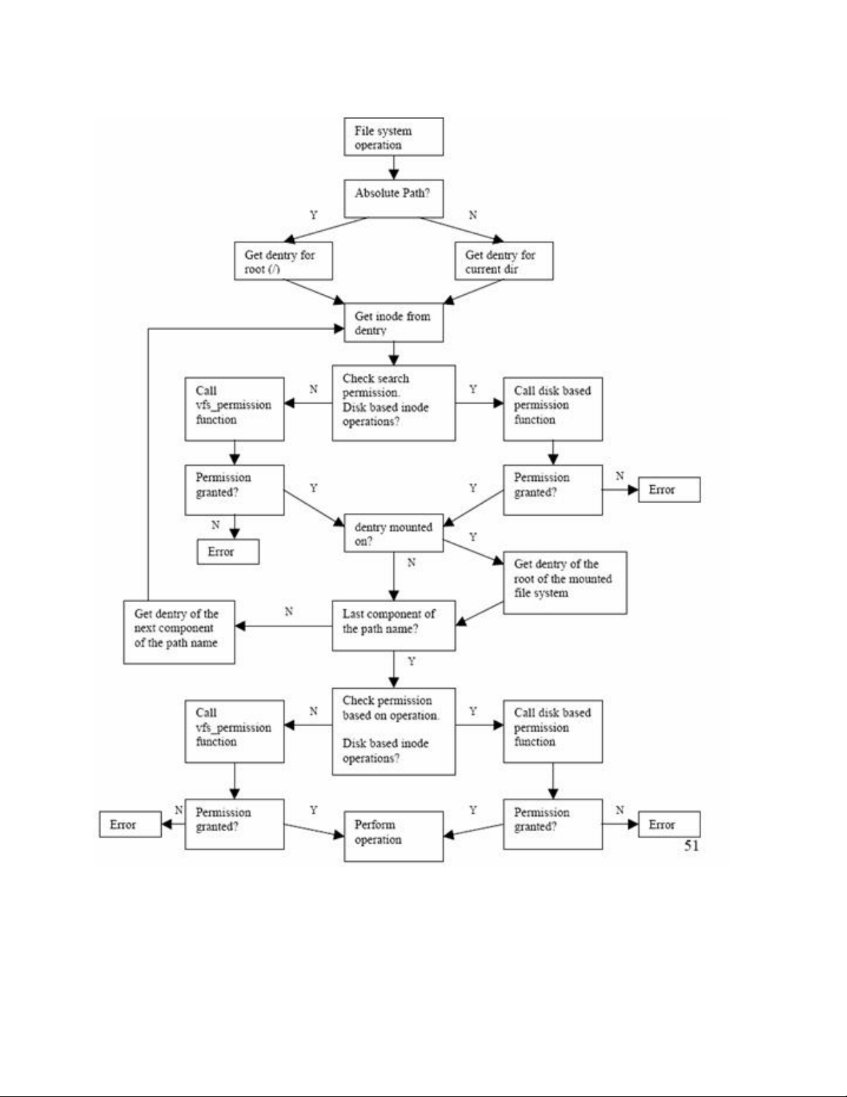
Figure 5-5: VFS pathname translation and access control checks
Figure 5-5 VFS pathname translation and access control checks
36
Page 49

5.1.1.2 open()
The following describes the call sequence of an open() call to create a file:
1. Call the open() system call with a relative pathname and flags to create a file for read and write.
2. open() calls open_namei(), which ultimately derives the dentry for the directory in which
the file is being created. If the pathname contains multiple directories, search permission for all
directories in the path is required to get access to the file.
This search permission check is performed for each directory dentry by calling permission().
If the operation vector of the inode, which contains pointers to valid inode operation routines, is
set, then each call to permission() is diverted to the disk-based file system-specific permission
call. Otherwise, generic_permission() is called, to ensure that the process has the appropriate
permission. If at this stage the process has the DAC permission, because either the generic or diskbased file system granted the permission, then AppArmor permission is checked through the
security_inode_permission() LSM call.
3. Once the directory dentry is found, permission() is called to make sure the process is
authorized to write in this directory. Again, if the operation vector of the inode is set, then the call
to permission() is diverted to the disk-based file system-specific permission call; otherwise
generic_permission() is called to ensure that the process has the appropriate permission. If at
this stage the process has the DAC permission, because either the generic or disk-based file system
granted the permission, then AppArmor permission is checked through the
security_inode_permission() LSM call.
4. If the user is authorized to create a file in this directory, then get_empty_filp() is called to get
a file pointer. get_empty_filp() calls memset() to ensure that the newly allocated file
pointer is zeroed out, thus taking care of the object reuse requirement. To create the file,
get_empty_filp() calls the disk-based file system-specific open routine through the file
operations vector in the file pointer.
At this point, data structures for the file object, dentry object, and inode object for the newly created file
are set up correctly, whereby the process can access the inode by following a pointer chain leading from the
file object to the dentry object to the inode object. The following diagram shows the simplified
linkage:
Figure 5-6: VFS data structures and their relationships with each other
37
Page 50

5.1.1.3 write()
Another example of a file system operation is a write() system call to write to a file that was opened for
writing. The write() system call in VFS is very straightforward, because access checks have already been
performed by open(). The following list shows the call sequence of a write() call:
1. Call the write() system call with the file descriptor that was returned by open().
2. Call fget() to get the file pointer corresponding to the file descriptor.
3. If the file operation vector of the file pointer is set, use the inode operation vector to call the diskbased file system’s write() routine of the disk-based file system.
5.1.1.4 mount()
An administrator mounts file systems using the mount() system call. The mount() system call provides
the kernel with the following:
● the file system type
● the pathname of the mount point
● the pathname of the block device that contains the file system
● the flags that control the behavior of the mounted file system
● a pointer to a file system dependent data structure (that may be NULL).
For each mount operation, the kernel saves the mount point and the mount flags in mounted file system
descriptors. Each mounted file system descriptor is a vfsmount type of data structure. The
sys_mount() function in the kernel copies the value of the parameters into temporary kernel buffers,
acquires the big kernel lock, and invokes the do_mount() function to perform the mount.
There are no object reuse issues to handle during file system mounting because the data structures created are
not directly accessible to user processes. However, there are security-relevant mount flags that affect access
control. Following are the security-relevant mount flags and their implications for access control.
• MS_RDONLY: The file system is mounted in read-only mode. Write operations are prohibited for all
files regardless of their mode bits.
• MS_NOSUID: the kernel ignores suid and sgid bits on executables when executing files from this file
system.
• MS_NODEV: Device access to a character or block device is not permitted from files on this file
system.
• MS_NOEXEC: Execution of any programs from this file system is not permitted, even if the execute
bit is set for the program binary.
• MS_POSIXACL: Indicates if ACLs on files on this file system are to be honored or ignored.
5.1.1.5 Shared subtrees
Shared subtrees have been implemented in VFS. This allows an administrator to configure the way the file
system mounts will coexist in the tree, the relationships between them, and how they propagate in different
namespaces. This increases flexibility in the way namespaces can be populated and presented to users. For
detailed information about the shared-subtree feature, see http://lwn.net/Articles/159077 and
http://lwn.net/Articles/159092.
The shared-subtree feature introduces new types of mounts:
38
Page 51

• Unbindable Mount: This mount does not forward or receive propagation. This mount type can not be
bind-mounted, and it is not valid to move it under a shared mount.
• Slave Mount: A slave mount remains tied to its parent mount and receives new mount or unmount
events from there. The mount or unmount events in a slave mount do not propagate elsewhere.
• Shared Mount: When this mount is used, all events generated are automatically propagated to the
shared mount subtree. Shared mounts are able to propagate events to others belonging to the same
peer group.
• Private Mount: This works as the previous existent mount. Private mounts cannot be propagated to
any other mounts, except when forced by administrators using the bind operation. Any kind of
mounts can be converted to private mounts.
5.1.2 Disk-based file systems
Disk-based file systems deal with how the data is stored on the disk. Different disk-based file systems
employ different layouts and support different operations on them. For example, the CD-ROM file system
does not support the write operation. The TOE supports two disk-based file systems: ext3, and the ISO 9660
File System for CD-ROM.
This section looks at data structures and algorithms used to implement these two disk-based file systems and
continues the description of open() and write() system calls in the context of disk-based file systems.
5.1.2.1 Ext3 file system
The SLES kernel’s ext3 file system kernel is a robust and efficient file system that supports the following:
• Automatic consistency checks
• Immutable files
• Preallocation of disk blocks to regular files
• Fast symbolic links
• ACLs
• Journaling
The file system partitions disk blocks into groups. Each group includes data blocks and inode blocks in
adjacent tracks, which allow files to be accessed with a lower average disk seek time. In addition to the
traditional UNIX file object attributes such as owner, group, permission bits, and access times, the SLES ext3
file system supports Access Control Lists (ACLs) and Extended Attributes (EAs). ACLs provide a flexible
method for granting or denying access, which is granular down to an individual user, directory, or file.
5.1.2.1.1 Extended Attributes
An extended attribute (EA, aka xattr) provides a mechanism for setting special flags on a directory or a file.
Some of these improve the usability of the system, while others improve the security of the system. EAs also
provide a mechanism that allows persistent storage of security attributes—DAC ACLs.
The EA namespace is partitioned. ACLs make use of reserved namespaces with access restricted to
administrative users (and object owner in some cases). Special checks are performed in the xattr syscalls to
ensure that only administrative users and privileged system services can access the reserved namespaces. The
system.posix_acl_access and system.posix_acl_default namespaces are reserved for ACL metadata. This
namespace is restricted to the object owner and is accessible by administrative users.
39
Page 52
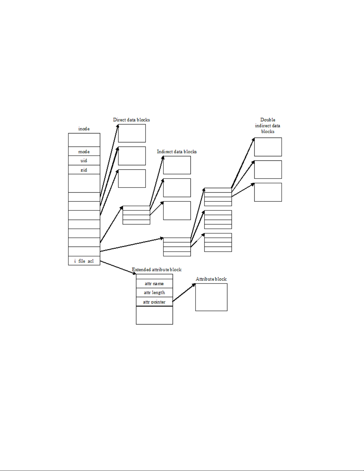
5.1.2.1.1.1 Access Control Lists
ACLs provide a way of extending directory and file access restrictions beyond the traditional owner, group,
and world permission settings. For more details about the ACL format, refer to Discretionary Access Control,
Section 5.1.5, of this document, and section 6.2.4.3 of the SLES Security Target document. EAs are stored on
disk blocks allocated outside of an inode. Security-relevant EAs provide the following functionality:
• Immutable: if this attribute is set, the file cannot be modified, no link can be created to it, and it
cannot be renamed or removed. Only an administrator can change this attribute.
• Append only: if this attribute is set, the file may only be modified in append mode. The append only
attribute is useful for system logs.
Figure 5-7: Security attributes, extended security attributes, and data blocks for
the ext3 inode
5.1.2.1.2 Data structures
The following data structures and inode operations illustrate how the ext3 file system performs DAC and
object reuse.
• ext3_super_block: The on-disk counterpart of the superblock structure of VFS,
ext3_super_block stores file system-specific information such as the total number of inodes,
block size, and fragment size.
40
Page 53

• ext3_group_desc: Disk blocks are partitioned into groups. Each group has its own group descriptor.
ext3_group_desc stores information such as the block number of the inode bitmap, and the
block number of the block bitmap.
• ext3_inode: The on-disk counterpart of the inode structure of VFS, ext3_inode stores
information such as file owner, file type and access rights, file length in bytes, time of last file access,
number of data blocks, pointer to data blocks, and file access control list.
• ext3_xattr_entry: This structure describes an extended attribute entry. The ext3_xattr_entry
stores information such as attribute name, attribute size, and the disk block that stores the attribute.
ACLs are stored on disk using this data structure, and associated to an inode by pointing the
inode’s i_file_acl field to this allocated extended attribute block.
• ext3_create(): This routine is called when a file create operation makes a transition from VFS to a
disk-based file system. ext3_create() starts journaling, and then calls ext3_new_inode()
to create the new inode.
• ext3_lookup(): This routine is called when VFS real_lookup() calls the disk-based file system
lookup routine of the disk-based file system through the inode operation vector. The
ext3_find_entry() is called by ext3_lookup() to locate an entry in a specified directory
with the given name.
• ext3_permission(): This is the entry point for all Discretionary Access Checks (DACs). This routine
is invoked when VFS calls to the permission() routine are diverted based on the ext3 inode’s
inode operation vector i_op of the ext3 inode. ext3_permission() calls
generic_permission().
• ext3_get_block(): This is the general-purpose routine for locating data that corresponds to a regular
file. ext3_get_block() is invoked when the kernel is looking for, or allocating, a new data
block. The routine is called from routines set up in the address-space operations vector, a_ops,
which is accessed through the inode’s i_mapping field of the inode. ext3_get_block() calls
ext3_get_block_handle(), which in turn calls ext3_alloc_branch() if a new data
block needs to be allocated. ext3_alloc_branch() explicitly calls memset() to zero-out the
newly allocated block, thus taking care of the object reuse requirement.
Figure 5-8 illustrates how new data blocks are allocated and initialized for an ext3 file.
41
Page 54

Figure 5-8: New data blocks are allocated and initialized for an ext3 field
42
Page 55
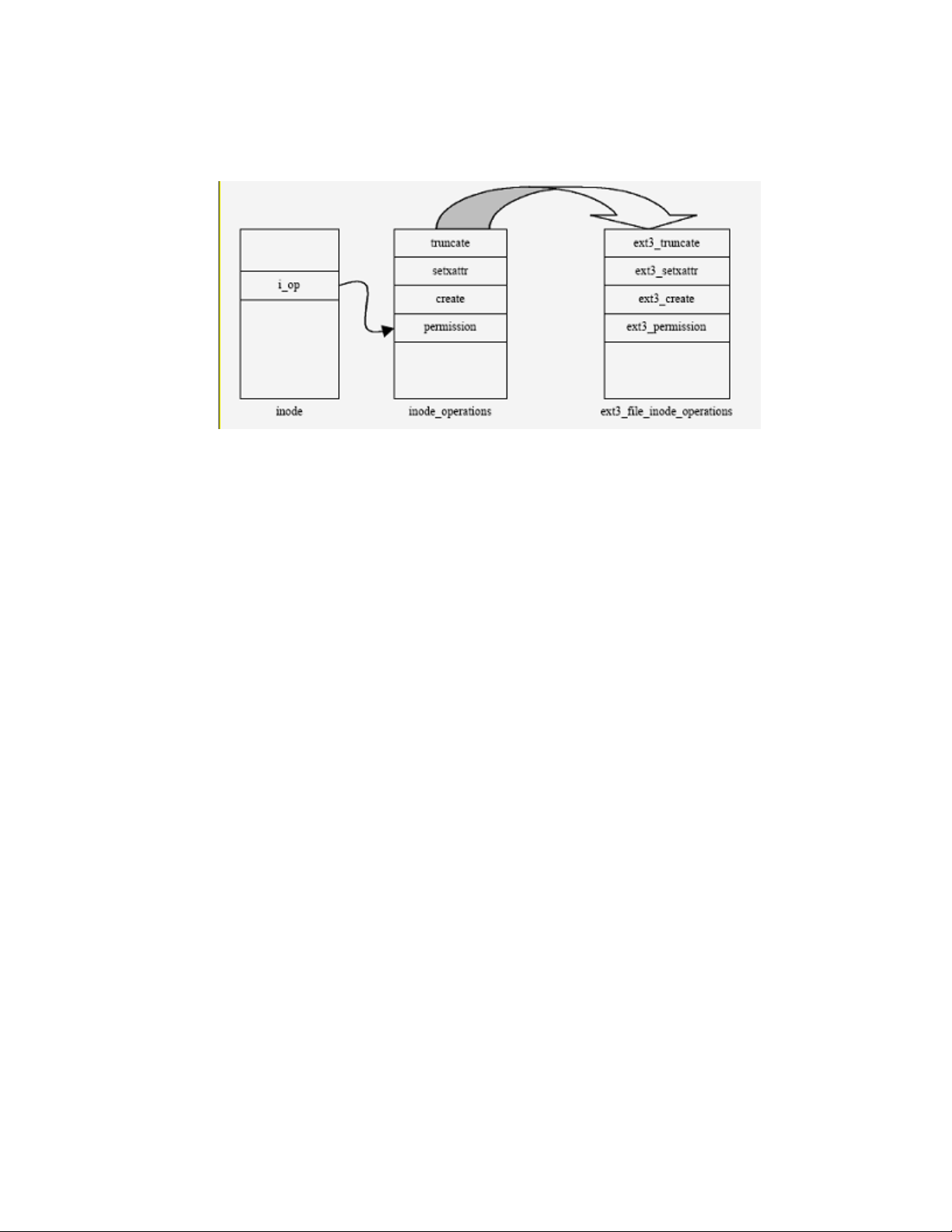
Figure 5-9 shows how for a file on the ext3 file system, inode_operations map to
ext3_file_inode_operations.
Figure 5-9: Access control on ext3 file system
Similarly, for directory, symlink, and special-file types of objects, inode operations map to
ext3_dir_inode_operations, ext3_symlink_inode_operations, and
ext3_special_inode_operations, respectively.
ext3_truncate() is the entry point for truncating a file. The ext3_truncate() routine is invoked
when VFS calls to the sys_truncate() routine are diverted based on the ext3 inode’s inode operation
vector i_op of the ext3 inode. This routine prevents the truncation of inodes whose extended attributes
mark them as being append-only or immutable.
5.1.2.2 ISO 9660 file system for CD-ROM
The SLES kernel supports the ISO 9660 file system for CD-ROM. Refer to the HOWTO document by
Martin Hinner on the Linux Documentation Project Web site for a detailed specification of the ISO 9660 file
system: http://www.tldp.org/HOWTO/Filesystems-HOWTO.html.
5.1.2.2.1 Data structures and algorithms
The following data structures and inode operations implement the file system on the SLES kernel.
• vfs_permission(): Because the file system is a read-only file system, there are no object reuse
implications with respect to allocating data blocks. The discretionary access check is performed at
the VFS layer with the vfs_permission() routine, which grants permission based on a process’s
fsuid field.
• isofs_sb_info: The CD-ROM file system super block isofs_sb_info stores file system-specific
information, such as the number of inodes, number of zones, maximum size, and fields for the mount
command line option to prohibit the execution of suid programs.
• iso_inode_info: The iso_inode_info is in-core inode information for CD-ROM file objects.
iso_inode_info stores information, such as file format, extent location, and a link to the next inode.
• isofs_lookup(): The isofs_lookup() on inode is called when the pathname translation routine is
diverted from the VFS layer to the isofs layer. isofs_lookup() sets the inode operation vector
43
Page 56

from the superblock’s s_root field of the superblock, and then invokes isofs_find_entry() to
retrieve the object from the CD-ROM.
On a CD-ROM file system, inode_operations map to isofs_dir_inode_operations.
Figure 5-10: File lookup on CD-ROM file system
5.1.3 Pseudo file systems
5.1.3.1 procfs
The proc file system is a special file system that allows system programs and administrators to manipulate the
data structures of the kernel. The proc file system is mounted at /proc, and provides Virtual File System
access to information about current running processes and kernel data structures.
An administrator can change kernel parameters, such as IP_FORWRDING, by editing files in /proc. For
each active process, the kernel creates a directory entry, named after the process ID, in the /proc directory.
This directory contains pseudo files that can be used to read the status of the process. The Process ID
directory is created with a mode of 555 and is owned by the user ID and group ID of the process. Access
control is performed by the VFS pathname translation mechanism function vfs_permission(), which
prevents access by normal users to data of other processes. In addition to vfs_permission(), different
files in the proc file system define their own access control service functions. These service functions
sometimes perform an additional access check that may restrict DAC decisions further.
Root can change permissions for files in /proc. The pseudo files within the process directory are only
readable for others as far as they provide information similar to the ps command. Because files in /proc
are not real disk-based files with user data, there is no object reuse issue.
5.1.3.2 tmpfs
tmpfs is a memory-based file system that uses virtual memory (VM) resources to store files. tmpfs is
designed primarily as a performance enhancement to allow short-lived files to be written and accessed
without generating disk or network I/O. tmpfs maximizes file manipulation speed while preserving file
semantics.
tmpfs also has dynamic file system size. As a file gets created, the tmpfs file system driver will allocate more
VM resources and dynamically increase file system size. In the same way as files get deleted, the file system
driver shrinks the size of file system and deallocates VM resources.
44
Page 57

Since VM is volatile in nature, tmpfs data is not preserved between reboots. Hence this file system is used to
store short-lived temporary files. An administrator is allowed to specify the memory placement policies (the
policy itself and the preferred nodes to be allocated) for this file system.
5.1.3.3 sysfs
sysfs is an in-memory file system, which acts as repository for system and device status information,
providing a hierarchical view of the system device tree. The system information that is dynamically
maintained in the sysfs file system is analogous to the process status information that is dynamically
maintained in the proc file system.
sysfs is typically mounted on /sys. It is a window into the kernel, and into the data objects that the kernel
creates and controls.
sysfs is created on boot, and automatically populated when internal objects are registered with their
subsystems. Because of its nature and its design, the hierarchy it creates is a completely accurate
representation of the kernel's internals. An administrator can change kernel object parameters by editing files
in /sys. Access Control is performed by the VFS pathname translation mechanism function
vfs_permission(), which prevents access by normal users to data belonging to the kernel.
The kernel initially determines permissions for files in /sys, but these can be changed. Since files in /sys
are not real disk-based files, there is no object reuse issue with user data.
5.1.3.4 devpts
The devpts file system is a special file system that provides pseudo terminal support. Pseudo terminals are
implemented as character devices. A pair of character device-special files, one corresponding to the master
device and the other corresponding to the slave device, represent a pseudo terminal. The slave device
provides a terminal interface. Instead of a hardware interface and associated hardware supporting the
terminal functions, a process that manipulates the master device of the pseudo terminal implements the
interface.
Any data written on the master device is delivered to the slave device, as though it had been received from a
hardware interface. Any data written on the slave device can be read from the master device.
In order to acquire a pseudo terminal, a process opens the /dev/ptmx master device. The system then
makes available to the process number a slave, which can be accessed as /dev/pts/number. An
administrator can mount the devpts special file system by providing uid, gid, and mode values on the mount
command line. If specified, these values set the owner, group, and mode of the newly created pseudo
terminals to the specified values.
In terms of access control, pseudo terminal devices are identical to device special files. Therefore, access
control is performed by the VFS pathname translation mechanism function vfs_permission(). Because
files in /dev/pts are not real disk-based files with user data, there is no object reuse issue.
5.1.3.5 rootfs
rootfs is a special file system that the kernel mounts during system initialization. This file system provides an
empty directory that serves as an initial mount point, where temporary files can be stored during the boot
process. Then, the kernel mounts the real root file system over the empty directory. The rootfs file system
allows the kernel to easily change the root file system. Because rootfs uses an empty directory that is
replaced by the real root file system before the init process starts, there is no issue of object reuse.
The rootfs is used internally in the kernel when doing root mounting. Because a real file system uses and
replaces rootfs before the init process, there is no mechanism to access it.
45
Page 58

5.1.3.6 binfmt_misc
binfmt_misc provides the ability to register additional binary formats to the kernel without compiling an
additional module or kernel. Therefore, binfmt_misc needs to know magic numbers at the beginning, or the
filename extension of the binary.
binfmt_misc works by maintaining a linked list of structs that contain a description of a binary format,
including a magic number with size, or the filename extension, offset and mask, and the interpreter name. On
request it invokes the given interpreter with the original program as an argument. Because binfmt_misc does
not define any default binary-formats, one has to register an additional binary-format. Because files in
/proc/sys/binfmt_misc are not real disk-based files with user data, there is no object reuse issue.
Refer to kernel-2.6.18/linux-2.6.18/Documentation/binfmt_misc.txt for a detailed
specification of binfmt_misc.
5.1.3.7 securityfs
Linux Security Modules (LSMs) use securityfs, which is a new virtual file system, avoiding some of the other
LSMs to create their own file systems. securityfs must be mounted on /sys/kernel/security. To
users it appears to be part of the sysfs, but it is a new and distinct one.
5.1.3.8 configfs
configfs is a RAM-based pseudo file system manager of kernel objects. It provides a converse of sysfs
functionality through a user space driver kernel object configuration. For additional information about
configfs, refer to http://lwn.net/Articles/148973 and http://lwn.net/Articles/149005.
5.1.4 inotify
inotify is a mechanism for watching and communicating file system events to user space. It is an
improvement and replacement of the dnotify tool, which had the same purpose. inotify is relevant because
different sorts of applications might want or need to know when events such as file changes or creation
happen. An example of the use of inotify is with security monitoring applications that must know of, and can
benefit from being told about, file system changes.
inotify uses a syscall interface. Applications open a watch file descriptor via the inotify_init() call
and register watches via the inotify_add_watch() call. To add a watch, an application must have
DAC read permission on the inode. The access checks are performed by the vfs_permission()
function. For more information on inotify, see the inotify(7) manage,
Documentation/filesystems/inotify.txt in the SLES kernel source available.
5.1.5 Discretionary Access Control (DAC)
Previous sections have described how appropriate *_permission() functions are called to perform access
checks for non-disk-based and disk-based file systems. Access checks are based on the credentials of the
process attempting access, and access rights assigned to the object.
When a file system object is created, the creator becomes the owner of the object. The group ownership
(group ID) of the object is set either to the effective group ID of the creator, or to the group ID of the parent
directory, depending on the mount options and the mode of the parent directory.
If the file system is mounted with the grpid option, then the object takes the group ID of the directory in
which it is created; otherwise, by default, the object takes the effective group ID of the creator, unless the
directory has the setgid bit set, in which case the object takes the GID from the parent directory, and also gets
the setgid bit set if it is a directory itself. This ownership can be transferred to another user by invoking the
46
Page 59

chown() system call. The owner and the root user are allowed to define and change access rights for an
object.
This following subsection looks at the kernel functions implementing the access checks. The function used
depends on the file system; for example, vfs_permission() invokes permission() which then calls
specific *_permission() routines based on the inode’s inode operation vector i_op.
proc_permission() is called for files in procfs. ext3_permission() is called for the ext3 diskbased file system. If no file system specific *_permission() routine was registered,
generic_permission() is called to perform the access checks. For some file systems including ext3,
the specific *_permission() routine invokes generic_permission(). Note that access rights are checked
when a file is opened and not on each access. Therefore, modifications to the access rights of file system
objects become effective at the next request to open the file.
AppArmor may optionally be loaded. AppArmor additionally restricts which files certain programs may
access. AppArmor is controlled by profiles in the /etc/apparmor.d directory. When loaded, AppArmor
applies additional restrictions to ping, syslogd, klogd, netstat, traceroute, lld, named,
identd, nscd, ntpd, and mdnsd. Additional profiles may be created by an authorized administrator.
AppArmor can run without affecting the TOE security functions because AppArmor will only add
restrictions, it will not allow what is denied. Whenever DAC denies an operation, AppArmor is not even
consulted.
5.1.5.1 Permission bits
generic_permission() implements standard UNIX permission bits to provide DAC for file system
objects for the procfs, devpts, sysfs, tmpfs, securityfs, binfmt_misc, and ISO 9660 file systems. As noted in
Section 5.1.3.5, there is no mechanism for accessing rootfs.
The ext3 file system uses the permission bits for files that do not have associated ACL information. This is
implemented in the generic_permission() function.
There are three sets of three bits that define access for three categories of users: the owning user, users in the
owning group, and other users. The three bits in each set indicate the access permissions granted to each user
category: one bit for read (r), one for write (w), and one for execute (x). Note that write access to file systems
mounted as read only, such as CDROM, is always rejected. Each subject’s access to an object is defined by
some combination of these bits:
rwx indicates read, write, and execute
r-x indicates read and execute
r-- indicates read
--- indicates null
When a process attempts to reference an object protected only by permission bits, the access is determined as
follows:
• Users with an effective user ID of 0 are able to read and write all files, ignoring the permission bits.
Users with an effective user ID of zero are also able to execute any file if it is executable for
someone.
• If the file system UID equals the object-owning UID, and the owning user permission bits allow the
type of access requested, access is granted with no further checks.
• If the file system GID, or any supplementary groups of the process equal an object’s owning GID,
and the owning group permission bits allow the type of access requested, access is granted with no
further checks.
47
Page 60

• If the process is neither the owner nor a member of an appropriate group, and the permission bits for
world allow the type of access requested, then the subject is permitted access.
• If none of the conditions above are satisfied, and the effective UID of the process is not zero, then the
access attempt is denied.
5.1.5.2 Access Control Lists
The ext3 file system supports Access Control Lists (ACLs) that offer more flexibility than the traditional
permission bits. An ACL can enforce specific access rights for multiple individual users and groups, not just
for the single user and group defined for permission-bit based access control.
The ext3_check_acl() function checks if an object has an associated ACL. If it does not have one, the
system uses the standard permission bits algorithm as described in the previous section.
If the file system object has an associated ACL, the kernel calls the posix_acl_permission() function
to enforce POSIX ACLs. ACLs are created, maintained, and used by the kernel. For more detailed
information about the POSIX ACLs, refer to the http://acl.bestbits.at and
http://wt.xpilot.org/publications/posix.1e sites.
An ACL entry contains the following information:
• A type of tag that specifies the type of the ACL entry.
• A qualifier that specifies an instance a type of an ACL entry.
• A permission set that specifies the discretionary access rights for processes identified by the tag type
and qualifier.
5.1.5.2.1 Types of ACL tags
The following types of tags exist:
• ACL_GROUP: This type of ACL entry defines access rights for processes whose file system group ID
or any supplementary group IDs match the one in the ACL entry qualifier.
• ACL_GROUP_OBJ: This type of ACL entry defines access rights for processes whose file system
group ID or any supplementary group IDs match the group ID of the group of the file.
• ACL_MASK: This type of ACL entry defines the maximum discretionary access rights for a process
in the file group class.
• ACL_OTHER: This type of ACL entry of this type defines access rights for processes whose
attributes do not match any other entry in the ACL.
• ACL_USER: An ACL entry of this type defines access rights for processes whose file system user ID
matches the ACL entry qualifier.
• ACL_USER_OBJ: An ACL entry of this type defines access rights for processes whose file system
user ID matches the user ID of the owner of the file.
5.1.5.2.2 ACL qualifier
The qualifier is required for the ACL_GROUP and ACL_USER ACL types of entries, and contain either the
user ID or the group ID for which the access rights are defined.
48
Page 61

5.1.5.2.3 ACL permissions
An ACL entry can define separate permissions for read, write, and execute or search.
5.1.5.2.4 Relationship to file permission bits
An ACL contains exactly one entry for each of the ACL_USER_OBJ, ACL_GROUP_OBJ, and ACL_OTHER
types of tags, called the required ACL entries. An ACL can have between zero and a defined maximum
number of entries of the ACL_GROUP and ACL_USER types. An ACL that has only the three required ACL
entries is called a minimum ACL. ACLs with one or more ACL entries of the ACL_GROUP or ACL_USER
types are called extended ACLs.
The standard UNIX file permission bits as described in the previous section are equivalent to the entries in the
minimum ACL. The owner permission bits correspond to the entry of the ACL_USER_OBJ type. The entry
of the ACL_GROUP_OBJ type represents the permission bits of the file group. The entry of the ACL_OTHER
type represents the permission bits of processes running with an effective user ID and effective group ID or
supplementary group ID different from those defined in ACL_USER_OBJ and ACL_GROUP_OBJ entries.
Minimum ACLs do not need to be stored on disk. The permission information contained in the inode is
sufficient for the access check. When adding ACL entries to a file system object that did not previously have
an explicit ACL, the kernel creates a minimum ACL based on the inode attributes, and then adds the new
entries to that.
5.1.5.2.5 ACL_MASK
If an ACL contains an ACL_GROUP or ACL_USER type of entry, then exactly one entry of the ACL_MASK
type is required in the ACL. Otherwise, the ACL_MASK type of entry is optional.
5.1.5.2.6 Default ACLs and ACL inheritance
A default ACL is an additional ACL, which can be associated with a directory. This default ACL has no
effect on the access to this directory. Instead, the default ACL is used to initialize the ACL for any file that is
created in this directory. When an object is created within a directory, and the ACL is not defined with the
function creating the object, the new object inherits the default ACL of its parent directory as its initial ACL.
This is implemented by ext3_create(), which invokes ext3_new_inode(), which in turn invokes
ext3_init_acl() to set the initial ACL.
5.1.5.2.7 ACL representations and interfaces
ACLs are represented in the kernel as extended attributes. The kernel provides system calls such as
getxattr(), setxattr(), listxattr(), and removexattr() to create and manipulate extended
attributes. User space applications can use these system calls to create and maintain ACLs and other extended
attributes. However, ACL applications, instead of directly calling system calls, use library functions provided
by the POSIX 1003.1e compliant libacl.so. Inside the kernel, the system calls are implemented using the
getxattr, setxattr, listxattr, and removexattr inode operations. The kernel provides two
additional inode operations, get_posix_acl() and set_posix_acl(), to allow other parts of the
kernel to manipulate ACLs in an internal format that is more efficient to handle than the format used by the
inode xattr operations.
In the ext3 disk-based file system, extended attributes are stored in a block of data accessible through the
i_file_acl field of the inode. This extended attribute block stores name-value pairs for all extended
attributes associated with the inode. These attributes are retrieved and used by appropriate access control
functions.
49
Page 62

5.1.5.2.8 ACL enforcement
The ext3_permission() function uses ACLs to enforce DAC. The algorithm goes through the
following steps:
1. Performs checks such as “no write access if read-only file system” and “no write access if the file is
immutable.”
2. For ext3 file systems, the kernel calls the ext3_get_acl() to get the ACL corresponding to the
object. ext3_get_acl() calls ext3_xattr_get(), which in turn calls
ext3_acl_from_disk() to retrieve the extended attribute from the disk. If no ACL exists, the
kernel follows the permission bits algorithm described previously.
3. For ext3 file systems, the kernel invokes posix_acl_permission(). It goes through the
following algorithm:
If the file system user ID of the process matches the user ID of the file object owner,
then
if the ACL_USER_OBJ entry contains the requested permissions, access is granted,
else access is denied.
else if the file system user ID of the process matches the qualifier of any entry of type ACL_USER,
then
if the matching ACL_USER entry and the ACL_MASK entry contain the requested permissions, access
is granted,
else access is denied.
else if the file system group ID or any of the supplementary group IDs of the process match the
qualifier of the entry of type ACL_GROUP_OBJ, or the qualifier of any entry of type ACL_GROUP,
then
if the ACL_MASK entry and any of the matching ACL_GROUP_OBJ or ACL_GROUP entries contain
all the requested permissions, access is granted,
else access is denied.
else if the ACL_OTHER entry contains the requested permissions, access is granted.
else access is denied.
The ACL checking function cycles through each ACL entry to check if the process is authorized to access the
object in the attempted mode. Root is always allowed to override any read or write access denials based an
ACL entry. Root is allowed to override an attempted execute access only if an execute bit is set for owner,
group, or other.
For example, consider a file named /aclfile, with mode of 640. The file is owned by root and belongs to
the group root. Its default ACL, without the extended POSIX ACL, would be:
# owner: root
# group: root
user:: rwgroup::r-other::---
The file is readable and writeable by the root user, and readable by users belonging to the root group. Other
users have no access to the file. With POSIX ACLs, a more granular access control can be provided to this
50
Page 63

file by adding ACLs with the setfacl command. For example, the following command allows a user
named john read access to this file, even if john does not belong to the root group.
#setfacl –m user:john:4,mask::4 /aclfile
The ACL on file will look like:
# owner: root
# group: root
user:: rwuser:john:r—
group::r-mask::r-other::---
The mask field reflects the maximum permission that a user can get. Hence, as per the ACL, even though
john is not part of the root group, john is allowed read access to the file /aclfile.
5.1.6 Asynchronous I/O
Asynchronous I/O (AIO) enables even a single application thread to overlap I/O operations with other
processing, by providing an interface for submitting one or more I/O requests in one system call
(io_submit()) without waiting for completion, and a separate interface (io_getevents()) to reap
completed I/O operations associated with a given completion group.
General operation of asynchronous I/O proceeds as follows:
• Process sets up asynchronous I/O context, for files opened with O_DIRECT, using io_setup
system call.
• Process uses io_submit system call to submit a set of I/O operations.
• Process checks the completion of I/O operations using io_getevents.
• Process destroys the asynchronous I/O context using the io_destroy system call.
AIO uses the kernel bottom half mechanism of work queues to perform deferred work of AIO. io_setup
sets up a work queue named aio, to which AIO work is submitted.
Some of the capabilities and features provided by AIO are:
• The ability to submit multiple I/O requests with a single system call.
• The ability to submit an I/O request without waiting for its completion and to overlap the request with
other processing.
• Optimization of disk activity by the kernel through combining or reordering the individual requests of
a batched I/O variety.
• Better CPU utilization and system throughput by eliminating extra threads and reducing context
switches.
5.1.7 I/O scheduler
The I/O scheduler in Linux forms the interface between the generic block layer and the low-level device
drivers. The block layer provides functions that are utilized by the file systems and the virtual memory
manager to submit I/O requests to block devices. These requests are transformed by the I/O scheduler and
made available to the low-level device drivers. The device drivers consume the transformed requests and
forward them, by using device-specific protocols, to the actual device controllers that perform the I/O
operations. As prioritized resource management seeks to regulate the use of a disk subsystem by an
51
Page 64

application, the I/O scheduler is considered an important kernel component in the I/O path. SLES includes
four I/O scheduler options to optimize system performance.
5.1.7.1 Deadline I/O scheduler
The deadline I/O scheduler available in the Linux 2.6 kernel incorporates a per-request expiration-based
approach, and operates on five I/O queues. The basic idea behind the implementation is to aggressively
reorder requests to improve I/O performance, while simultaneously ensuring that no I/O request is being
starved. More specifically, the scheduler introduces the notion of a per-request deadline, which is used to
assign a higher preference to read than write requests.
As stated earlier, the deadline I/O scheduler maintains five I/O queues. During the enqueue phase, each I/O
request gets associated with a deadline, and is inserted into I/O queues that are either organized by starting
block (a sorted list) or by the deadline factor (a first-in-first-out [FIFO]) list. The scheduler incorporates
separate sort and FIFO lists for read and write requests, respectively. The fifth I/O queue contains the requests
that are to be handed off to the device driver. During a dequeue operation, in the case that the dispatch queue
is empty, requests are moved from one of the four I/O lists (sort or FIFO) in batches. The next step consists
of passing the head request on the dispatch queue to the device driver.
The logic behind moving the I/O requests from either the sort or the FIFO lists is based on the scheduler’s
goal to ensure that each read request is processed by its effective deadline without actually starving the
queued-up write requests. In this design, the goal of economizing on the disk seek time is accomplished by
moving a larger batch of requests from the sort list, which is sector sorted, and balancing it with a controlled
number of requests from the FIFO list.
5.1.7.2 Anticipatory I/O scheduler
The design of the anticipatory I/O scheduler attempts to reduce the per-thread read response time. It
introduces a controlled delay component into the dispatching equation. The delay is invoked on any new
request to the device driver, thereby allowing a thread that just finished its I/O request to submit a new
request.
Implementation of the anticipatory I/O scheduler is similar to, and may be considered as, an extension to the
deadline scheduler. In general, the scheduler follows the basic idea that if the disk drive just operated on a
read request, the assumption can be made that there is another read request in the pipeline, and hence it is
worthwhile to wait. The I/O scheduler starts a timer, and at this point, there are no more I/O requests passed
down to the device driver. If a close read request arrives during the wait time, it is serviced immediately, and
in the process, the actual distance that the kernel considers as close grows as time passes, which is the
adaptive part of the heuristic. Eventually the close requests dry out, causing the scheduler to submit some of
the write requests, converging back to what is considered a normal I/O request dispatching scenario.
5.1.7.3 Completely Fair Queuing scheduler
The Completely Fair Queuing (CFQ) I/O scheduler can be considered an extension to the Stochastic Fair
Queuing (SFQ) scheduler implementation. The focus of both implementations is on the concept of fair
allocation of I/O bandwidth among all the initiators of I/O requests. The actual implementation utilizes n
(normally 64) internal I/O queues, as well as a single I/O dispatch queue.
During an enqueue operation, the PID of the currently running process (the actual I/O request producer) is
utilized to select one of the internal queues, which is normally hash-based, and, hence, the request is inserted
into one of the queues in FIFO order. During dequeue, it calls for a round-robin based scan through the nonempty I/O queues, and selects requests from the head of the queues. To avoid encountering too many seek
operations, an entire round of requests is first collected, sorted, and ultimately merged into the dispatch queue.
Next, the head request in the dispatch queue is passed to the actual device driver. The CFQ I/O scheduler
implements time sharing, in which the processes possess time slices during which they can dispatch I/O
52
Page 65

requests. This capability makes it behaves similarly to the Anticipatory I/O scheduler. I/O priorities are also
considered for the processes, which are derived from their CPU priority.
5.1.7.4 Noop I/O scheduler
The noop I/O scheduler can be considered as a rather minimal I/O scheduler that performs, as well as
provides, basic merging and sorting functionalities. The main usage of the noop scheduler revolves around
non-disk-based block devices, such as memory devices, as well as specialized software or hardware
environments that incorporate their own I/O scheduling and large caching functionality, thus requiring only
minimal assistance from the kernel.
5.1.8 I/O interrupts
The Linux kernel supports concurrent execution of multiple tasks. Each active task gets a portion of the CPU
time to advance its execution. Apart from this, the CPU also has to respond to address space violations, page
faults, synchronous signals from the CPU control unit, and asynchronous signals from devices such as a
keyboard or a network card. This section describes how the Linux kernel handles these asynchronous
interrupts generated by I/O devices.
Various I/O devices, such as the keyboard, communicate with the CPU regarding events occurring in the
device, such as a key typed at the keyboard, by sending special electrical signals to the CPU. The CPU
receives the signal and communicates it to the kernel for processing. Depending on the signal, the kernel
executes an appropriate interrupt handler to process the event.
Responsiveness of the system can be increased by promptly handling the interrupts. However, depending on
the type of the interrupt, not all actions associated with handling an interrupt must be executed immediately.
Therefore, an interrupt handler can be thought to consist of two sets of operations.
The first set, which is called the top half, consists of operations that must be executed immediately. The
second set, which is called the bottom half, consists of operations that can be deferred. The top half usually
includes the most critical tasks, such as acknowledging the signal. The Linux kernel provides three
mechanisms for implementing a bottom half of an interrupt handler. They are softirqs, tasklets, and work
queues.
5.1.8.1 Top halves
Top halves perform critical parts of interrupt-related tasks such as acknowledging interrupts to the PIC,
reprogramming the PIC or device controller, and updating data structures accessed by both device and
processor.
5.1.8.2 Bottom halves
Bottom halves perform interrupt-related tasks that were not performed by the top half of the interrupt handler.
That is, bottom halves perform the work that was deferred by the top halves because it was not absolutely
necessary to perform it in the top half.
5.1.8.3 Softirqs
Softirqs are statically linked (defined at compile time) bottom halves that execute in the interrupt context.
Many softirqs can always be executed concurrently on several CPUs even if they are of same type.
53
Page 66

5.1.8.4 Tasklets
Tasklets are dynamically linked and built on top of softirq mechanisms. Tasklets differ from softirqs in that a
tasklet is always serialized with respect to itself. In other words, a tasklet cannot be executed by two CPUs at
the same time. However, different tasklets can be executed concurrently on several CPUs.
5.1.8.5 Work queue
The work queue mechanism was introduced in the 2.6 Linux kernel. Work queues execute in process context,
as opposed to the interrupt context of softirqs and tasklets. Work queues defer work to kernel threads, which
are schedulable, and can therefore sleep. Thus, work queues provide an interface to create kernel threads to
handle work queued from other operations. The work queue infrastructure allows a device driver to create its
own kernel thread or use generic worker threads, one per processor, provided by the kernel.
5.1.9 Processor interrupts
A symmetrical multiprocessing (SMP) system sets slightly different requirements to interrupt handling by
hardware and software than an ordinary uniprocessing (UP) system. Distributed handling of hardware
interrupts has to be implemented to take advantage of parallelism, and an efficient mechanism for
communicating between CPUs must be provided.
Inter-processor interrupts (IPIs) are used to exchange messages between CPUs in SMP system. The following
group of functions helps in issuing IPIs:
• send_IPI_all() Sends an IPI to all CPUs (including the sender)
• send_IPI_allbutself() Sends an IPI to all CPUs except the sender
• send_IPI_self() Sends an IPI to the sender CPU
• send_IPI_single() Sends an IPI to a single, specified CPU
On a multiprocessor system, Linux defines the following five types of IPIs:
• CALL_FUNCTION_VECTOR(vector 0xfb) Used to call functions with a given argument on other
CPUs like flush tlb_all_ipi() and stop_this_cpu(). Handler:
smp_call_function_interrupt().
• RESCHEDULE_VECTOR(0xfc) Used at least when the best CPU for the woken up task is not this
CPU. Handler: smp_reschedule_interrupt().
• INVALIDATE_TLB_VECTOR(VECTOR 0xfd) Used when the TLBs of the other CPU need to be
invalidated. Handler: smp_invalidate_interrupt().
• ERROR_APIC_VECTOR(vector 0xfe) This interrupt should never occur.
• SPURIOUS_APIC_VECTOR(vector 0xff) This interrupt should never occur.
5.1.10 Machine check
A machine check exception is an imprecise non-recoverable exception, which means that the CPU does not
guarantee it will give a coherent set of register values after the exception occurs. A machine check exception
occurs when something goes wrong inside the CPU, such as cosmic rays causing bits to randomly flip, or the
CPU overheating causing electrons to drift.
54
Page 67
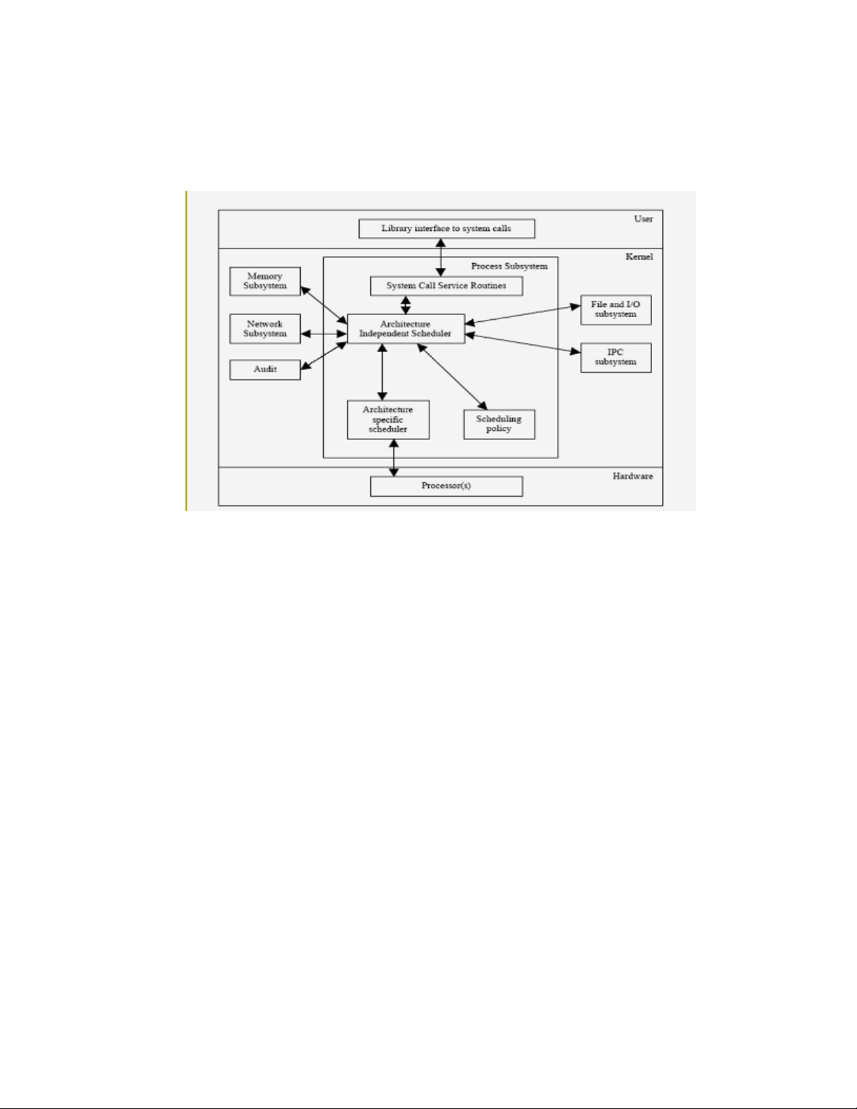
5.2 Process control and management
A process is an instance of a program in execution. Process management consists of creating, manipulating,
and terminating a process. Process management is handled by the process management subsystems of the
kernel. The kernel interacts with the memory subsystem, the network subsystem, the file and I/O subsystem,
and the inter-process communication (IPC) subsystem.
SELinux
Figure 5-11: Process subsystem and its interaction with other subsystems
The kernel treats a process as a subject. A subject is an active entity that can access and manipulate data and
data repositories, which are objects. System resources, such as CPU time and memory, are allocated to
objects. The kernel manages a process through a number of data structures. These data structures are created,
manipulated, and destroyed to give processes viability.
This section briefly describes how a process is given credentials that are used in access mediation, and how
the credentials are affected by process and kernel actions during the life cycle of the process.
This section is divided into four subsections. Data Structures lists important structures that are used to
implement processes and highlight security relevant credentials fields. Process Creation and Destruction
describes creation, destruction, and maintenance of a process with emphasis on how security-relevant
credentials are affected by state transitions. Process Switch describes how the kernel switches the current
process that is executing on the processor, with emphasis on mechanisms that ensure a clean switch (that is,
ensuring that the latest process executing is not using any resources from the switched out process). Kernel
Threads describes special-purpose subjects that are created to perform critical system tasks.
5.2.1 Data structures
The SLES kernel provides two abstractions for subject constructs: a regular process and a lightweight process.
A lightweight process differs from a regular process in its ability to share some resources, such as address
space and open files. With respect to security relevance, if differences exist between regular processes and
lightweight processes, those differences are highlighted. Otherwise, both regular and lightweight processes
are simply referred to as processes for better readability.
55
Page 68

The SLES kernel maintains information about each process in a task_struct process type of descriptor.
Each process descriptor contains information such as run-state of process, address space, list of open files,
process priority, which files the process is allowed to access, and security relevant credentials fields including
the following:
• uid and gid, which describe the user ID and group ID of a process.
• euid and egid, which describe the effective user ID and effective group ID of a process.
• fsuid and fsgid, which describe the file system user ID and file system group ID of a process.
• suid and sgid, which describe the saved user ID and saved group ID of a process.
• groups, which lists the groups to which the process belongs.
• state, which describes the run state of the process.
• pid, which is the process identifier used by the kernel and user processes for identification.
• security, which points to the information relating to the process domain and other attributes used and
managed by AppArmor.
The credentials are used every time a process tries to access a file or IPC objects. Process credentials, along
with the access control data and ownership of the object, determine if access is allowed.
Refer to include/linux/sched.h for information about other task_struct fields.
Figure 5-12 schematically shows the task_struct structure with fields relevant for access control.
56
Page 69

Figure 5-12: The task structure
The kernel maintains a circular doubly-linked list of all existing process descriptors. The head of the list is the
init_task descriptor referenced by the first element of the task array. The init_task descriptor
belongs to process 0 or the swapper, the ancestor of all processes.
5.2.2 Process creation and destruction
The SLES kernel provides these system calls for creating a new process: clone(), fork(), and
vfork(). When a new process is created, resources owned by the parent process are duplicated in the child
process. Because this duplication is done using memory regions and demand paging, the object reuse
requirement is satisfied.
The vfork() system call differs from fork() by sharing the address space of its parent. To prevent the
parent from overwriting data needed by the child, the execution of the parent is blocked until the child exits or
executes a new program. Lightweight processes are created using the clone() system call, which allows
both the parent and the child to share many per-process kernel data structures such as paging tables, open file
tables, and signal dispositions.
5.2.2.1 Control of child processes
The child process inherits the parent’s security-relevant credentials, including uid, euid, gid, and egid.
Because these credentials are used for access control decisions, the child is given the same level of access to
objects as the parent. The credentials of a child changes when it starts executing a new program or issues
suitable system calls, which are listed as follows:
5.2.2.2 DAC controls
5.2.2.2.1 setuid()and setgid()
These set the effective user and group ID of the current process. If the effective user ID of the caller is root,
then the real and saved user and group IDs are also set.
5.2.2.2.2 seteuid()and setegid()
These set the effective user and group ID of the current process. Normal user processes may only set the
effective user and group ID to the real user and group ID, the effective user and group ID, or the saved user
and group ID.
5.2.2.2.3 setreuid()and setregid()
These set the real and effective user and group IDs of the current process. Normal users may only set the real
user and group ID to the real user and group ID or the effective user and group ID, and can only set the
effective user and group ID to the real user and group ID, the effective user and group ID or the saved user
and group ID. If the real user and group ID is set or the effective user and group ID is set to a value not equal
to the previous real user and group ID, the saved user and group ID is set to the new effective user and group
ID.
57
Page 70

5.2.2.2.4 setresuid()and setresgid()
These set the real user and group ID, the effective user and group ID, and the saved set-user and group ID of
the current process. Normal user processes (that is, processes with real, effective, and saved user IDs that are
nonzero) may change the real, effective, and saved user and group IDs to either the current uid and gid, the
current effective uid and gid, or the current saved uid and gid. An administrator can set the real, effective,
and saved user and group ID to an arbitrary value.
5.2.2.3 execve()
This invokes the exec_mmap() function to release the memory descriptor, all memory regions, and all page
frames assigned to the process, and to clean up the Page Tables of a process. The execve() function
invokes the do_mmap() function twice, first to create a new memory region that maps the text segment of
the executable, and then to create a new memory region that maps the data segment of the executable file.
The object reuse requirement is satisfied because memory region allocation follows the demand paging
technique described in Section 5.5.
execve() can also alter the credentials of the process if the setuid bit of the executable file is set. If the
setuid bit is set, the current euid and fsuid of the process are set to the identifier of the owner of the file. This
change of credentials affects process permissions for the DAC policy.
5.2.2.4 do_exit()
Process termination is handled in the kernel by the do_exit() function. The do_exit() function
removes most references to the terminating process from the kernel data structures and releases resources,
such as memory, open files, and semaphores held by the process.
5.2.3 Process switch
To control the execution of multiple processes, the SLES kernel suspends the execution of the process
currently running on the CPU and resumes the execution of some other process previously suspended. In
performing a process switch, the SLES kernel ensures that each register is loaded with the value it had when
the process was suspended. The set of data that must be loaded into registers is called the hardware context,
which is part of the larger process execution context. Part of the hardware context is contained in the task
structure of a process; the rest is saved in the kernel mode stack of a process, which allows for the separation
needed for a clean switch. In a three-step process, the switch is performed by:
1. installation of a new address space
2. switching the Kernel Mode Stack
3. switching the hardware context
5.2.4 Kernel threads
The SLES kernel delegates certain critical system tasks, such as flushing disk caches, swapping out unused
page frames, and servicing network connections, to kernel threads. Because kernel threads execute only in
kernel mode, they do not have to worry about credentials. Kernel threads satisfy the object reuse requirement
by allocating memory from the kernel memory pool, as described in the kernel memory management section
of this document.
58
Page 71
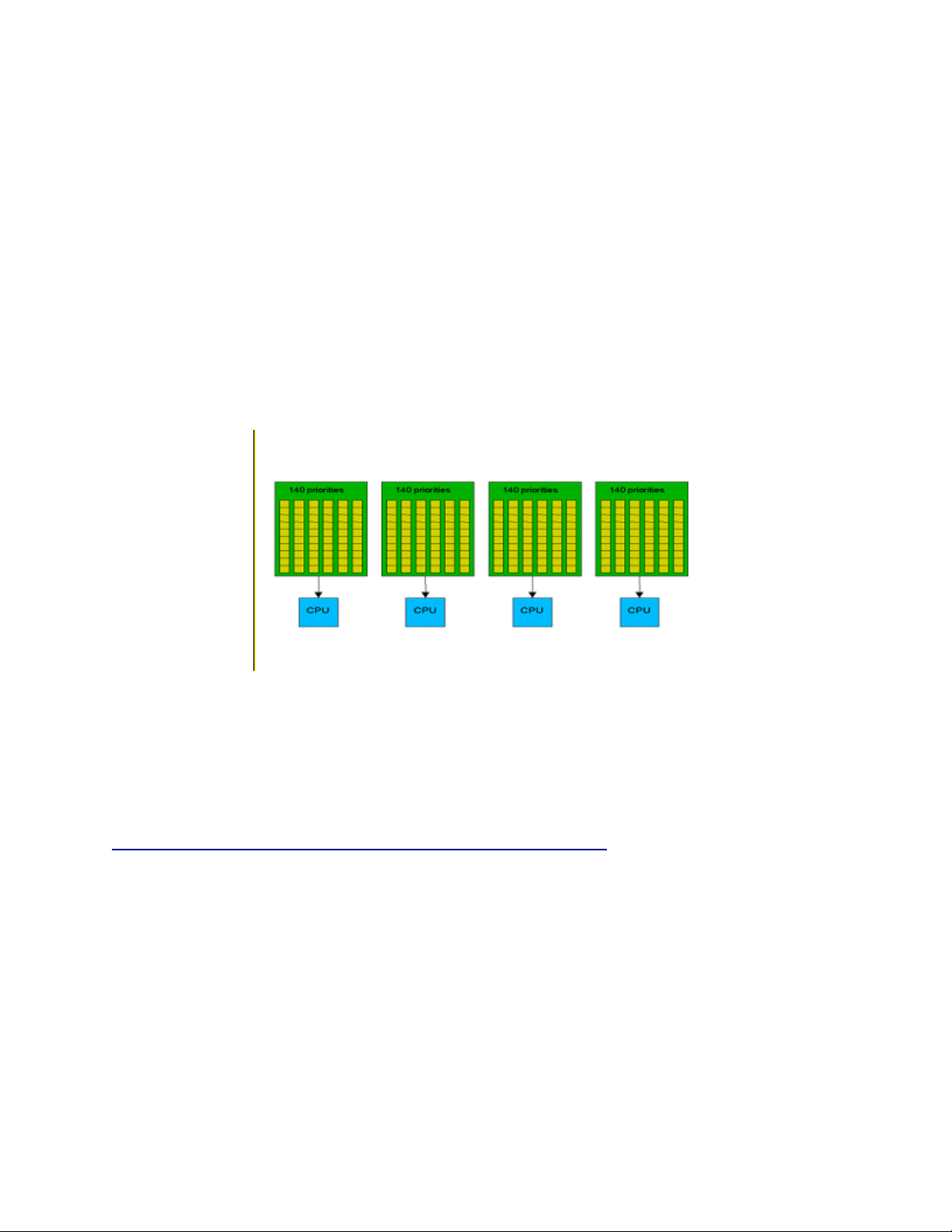
5.2.5 Scheduling
Scheduling is one of the features that is highly improved in the SLES 2.6 kernel over the 2.4 kernel. It uses a
new scheduler algorithm, called the O (1) algorithm, that provides greatly increased scheduling scalability.
The O (1) algorithm achieves this by taking care that the time taken to choose a process for placing into
execution is constant, regardless of the number of processes. The new scheduler scales well, regardless of
process count or processor count, and imposes a low overhead on the system.
In the Linux 2.6 scheduler, time to select the best task and get it on a processor is constant, regardless of the
load on the system or the number of CPUs for which it is scheduling.
Instead of one queue for the whole system, one active queue is created for each of the 140 possible priorities
for each CPU. As tasks gain or lose priority, they are dropped into the appropriate queue on the processor on
which they last ran. Now it is easy for a processor to find the highest priority task. As tasks complete their
time slices, they go into a set of 140 parallel queues, named the expired queues, per processor. When the
active queue is empty, a simple pointer assignment can cause the expired queue to become the active queue
again, making turnaround quite efficient.
Figure 5-13: O(1) scheduling
For more information about O(1) scheduling, refer to Linux Kernel Development - A Practical guide to the
design and implementation of the Linux Kernel, Chapter 3, by Robert Love, or “Towards Linux 2.6: A look
into the workings of the next new kernel” by Anand K. Santhanam at
http://www-106.ibm.com/developerworks/linux/library/l-inside.html#h1.
The SLES kernel also provides support for hyperthreaded CPUs that improves hyperthreaded CPU
performance. Hyperthreading is a technique in which a single physical processor masquerades at the
hardware level as two or more processors. It enables multi-threaded server software applications to execute
threads in parallel within each individual server processor, thereby improving transaction rates and response
times.
Hyperthreading scheduler
This section describes scheduler support for hyperthreaded CPUs. Hyperthreading support ensures that the
scheduler can distinguish between physical CPUs and logical, or hyperthreaded, CPUs. Scheduler compute
queues are implemented for each physical CPU, rather than each logical CPU as was previously the case.
This results in processes being evenly spread across physical CPUs, thereby maximizing utilization of
resources such as CPU caches and instruction buffers.
59
Page 72
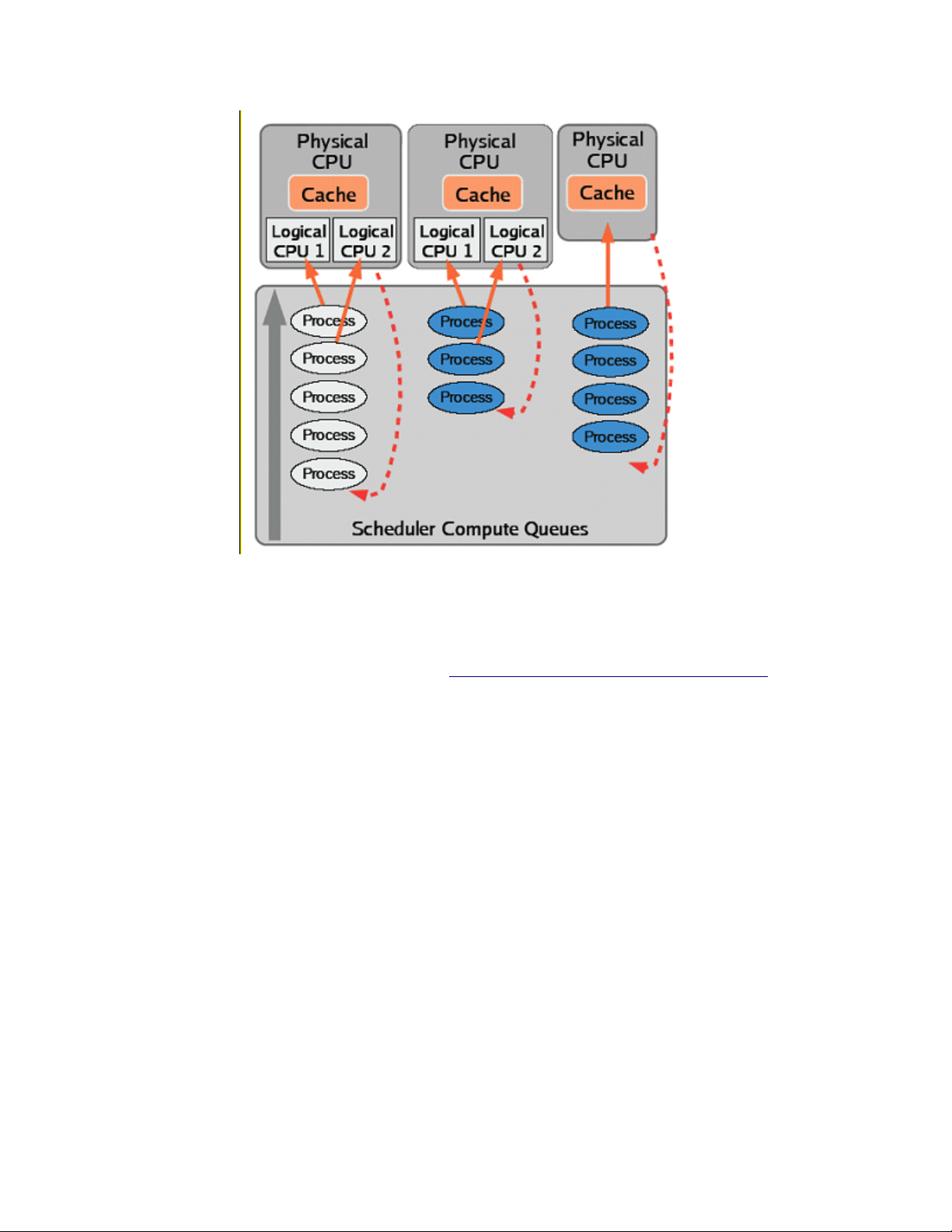
Figure 5-14: Hyperthreaded scheduling
For more information about hyperthreading, refer to http://www.intel.com/technology/hyperthread/.
5.2.6 Kernel preemption
The kernel preemption feature has been implemented in the Linux 2.6 kernel. This should significantly lower
latency times for user-interactive applications, multimedia applications, and the like. This feature is
especially good for real-time systems and embedded devices. In previous versions of the kernel it was not
possible to preempt a task executing in kernel mode, including user tasks that had entered into kernel mode
via system calls, until or unless the task voluntarily relinquished the CPU.
Because the kernel is preemptible, a kernel task can be preempted so that some important user applications
can continue to run. The main advantage of this is that there will be a big boost to user interactiveness of the
system, and the user will feel that things are happening at a faster pace for a key stroke or mouse click.
Of course, not all sections of the kernel code can be preempted. Certain critical sections of the kernel code
are locked against preemption. Locking should ensure that both per-CPU data structures and state are always
protected against preemption.
60
Page 73

The following code snippet demonstrates the per-CPU data structure problem, in an SMP system:
int arr[NR_CPUS];
arr[smp_processor_id()] = i;
/* kernel preemption could happen here */
j = arr[smp_processor_id()];
/* i and j are not equal as smp_processor_id() may not be the same */
In this situation, if kernel preemption had happened at the specified point, the task would have been assigned
to some other processor upon re-schedule, in which case smp_processor_id() would have returned a
different value. This situation should be prevented by locking.
FPU mode is another case where the state of the CPU should be protected from preemption. When the kernel
is executing floating point instructions, the FPU state is not saved. If preemption happens here, then upon
reschedule, the FPU state is completely different from what was there before preemption. So, FPU code must
always be locked against kernel preemption.
Locking can be done by disabling preemption for the critical section and re-enabling it afterwards. The Linux
2.6 kernel has provided the following #defines to disable and enable preemption:
• preempt_enable() -- decrements the preempt counter
• preempt_disable() -- increments the preempt counter
• get_cpu() -- calls preempt_disable() followed by a call to smp_processor_id()
• put_cpu() -- re-enables preemption
Using these #defines we could rewrite the above code as
int cpu, arr[NR_CPUS];
arr[get_cpu()] = i; /* disable preemption */
j = arr[smp_processor_id()];
/* do some critical stuff here */
put_cpu(); /* re-enable preemption */
Note that preempt_disable() and preempt_enable() calls are nested. That is,
preempt_disable() can be called n number of times, and preemption will only be re-enabled when the
nth preempt_enable() is encountered.
Preemption is implicitly disabled if any spin locks are held. For instance, a call to
spin_lock_irqsave() implicitly prevents preemption by calling preempt_disable(); a call to
spin_unlock_irqrestore() re-enables preemption by calling preempt_enable().
5.3 Inter-process communication
The SLES kernel provides a number of Inter-process communication (IPC) mechanisms that allow processes
to exchange arbitrary amounts of data and synchronize execution. The IPC mechanisms include unnamed
pipes, named pipes (FIFOs), the System V IPC mechanisms (consisting of message queues, semaphores and
shared memory regions), signals, and sockets.
This section describes the general functionality and implementation of each IPC mechanism and focuses on
DAC and object reuse handling.
61
Page 74
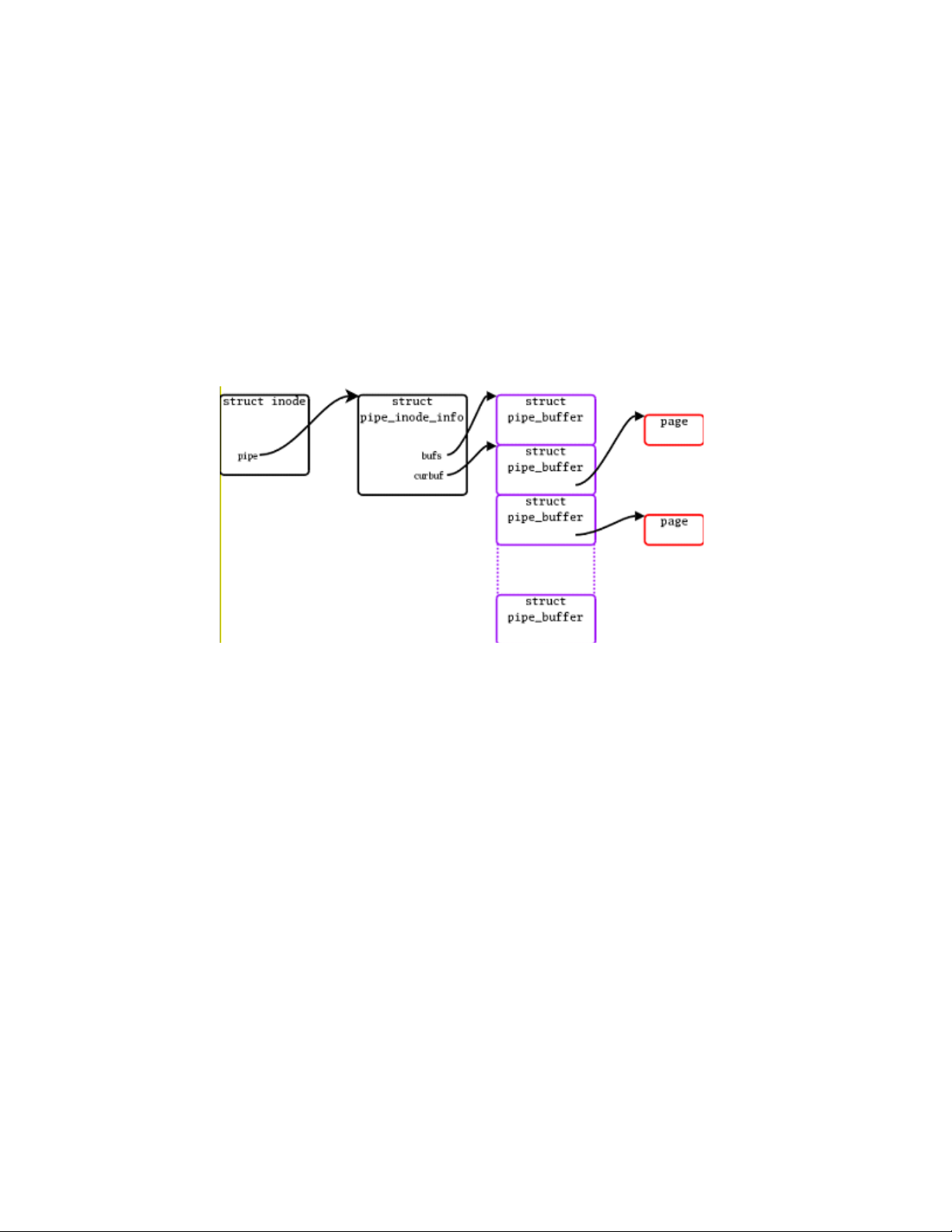
5.3.1 Pipes
Pipes allow the transfer of data in a FIFO manner. The pipe() system call creates unnamed pipes.
Unnamed pipes are only accessible to the creating process and its descendants through file descriptors. Once
a pipe is created, a process may use the read() and write() VFS system calls to access it.
In order to allow access from the VFS layer, the kernel creates an inode object and two file objects for each
pipe. One file object is used for reading (reader) and the other for writing (writer). It is the responsibility of
the process to use the appropriate file descriptor for reading and writing. Processes access unnamed pipes
through their VFS file descriptors. Hence, access control is performed at the VFS layer in the same manner
as for regular files, as described in Sections 5.1.5.
The internal implementation of pipes has changed with the 2.6 kernel. Before, a pipe used a single page to
buffer data between the file object reader and writer. For a process writing more than a single page, it became
blocked until the file object reader consumed the amount of data necessary to allow the rest to be fit in the
buffer. In the new implementation, known as circular pipes, a circular buffer is used.
Figure 5-15: Pipes Implementation
In a simple scenario, a curbuf pointer indicates the first buffer that contains data in the array, and nrbufs
indicates the number of buffers that contain data. The page structures are allocated and used as necessary. In
order to serialize access, the pipe semaphore is used, since file object writers and readers are able to
manipulate nrbufs. Length and offset fields compose the pipe buffer structure in order for each entry in the
circular buffer to be able to contain less than a full page of data.
This circular implementation improves pipe bandwidth from 30% to 90%, with a small increase in latency
because pages are allocated when data passes through the pipe. The better results in performance are
attributable to the large buffering, since file object readers and writers block less often when passing data
through the pipe.
This new functionality implemented in circular pipes is intended to become a general mechanism for
transmitting data streams through the kernel.
5.3.1.1 Data structures and algorithms
The inode object refers to a pipe with its i_pipe field, which points to a pipe_inode_info structure.
The pipe() system call invokes do_pipe() to create a pipe. The read() and write() operations
performed on the appropriate pipe file descriptors invoke, through the file operations vector f_op of the file
object, the pipe_read() and pipe_write() routines, respectively.
62
Page 75

pipe_inode_info: Contains generic state information about the pipe with fields such as base (which
points to the kernel buffer), len (which represents the number of bytes written into the buffer and yet to be
read), wait (which represents the wait queue), and start (which points to the read position in the kernel
buffer).
do_pipe(): Invoked through the pipe() system call, do_pipe() creates a pipe that performs the
following actions:
1. Allocates and initializes an inode.
2. Allocates a pipe_inode_info structure and stores its address in the i_pipe field of the
inode.
3. Allocates a page-frame buffer for the pipe buffer using __get_free_page(), which in turn
invokes alloc_pages() for the page allocation. Even though the allocated page is not
explicitly zeroed-out, because of the way pipe_read() and pipe_write() are written, it
is not possible to read beyond what the write channel writes. Therefore, there are no object reuse
issues.
pipe_read(): Invoked through the read() system call, pipe_read() reads the pipe buffer that the
base field of the pipe_info structure points to.
pipe_write(): Invoked through the write() system call, pipe_write() writes in the pipe buffer
pointed to by the base field of the pipe_info structure.
Because unnamed pipes can only be used by a process and its descendants that share file descriptors, there are
no DAC issues.
5.3.2 First-In First-Out Named pipes
A First-In First-Out (FIFO) named pipe is very similar to the unnamed pipe described in Section 5.3.1. Unlike
the unnamed pipe, a FIFO has an entry in the disk-based file system. A large portion of the internal
implementation of a FIFO pipe is identical to that of the unnamed pipe. Both use the same data structure,
pipe_inode_info, and the pipe_read() and pipe_write() routines. The only differences are that
FIFOs are visible on the system directory tree and are a bi-directional communication channel. Access
control on named pipes is also performed using interaction of processes with file descriptors in a similar
manner as for those of access control on regular files, as explained in Section 5.1.5 (DAC).
5.3.2.1 FIFO creation
FIFO exists as a persistent directory entry on the system directory tree. A FIFO is created with the VFS
mknod() system call, as follows:
1. The mknod() call uses the path name translation routines to obtain the dentry object of the
directory where the FIFO is to be created, and then invokes vfs_mknod().
2. The vfs_mknod() call crosses over to the disk-based file system layer by invoking the disk-based
file system version of mknod (ext3_mknod()) through the inode operations vector i_op.
3. A special FIFO inode is created and initialized. The file operation vector of the inode is set to
def_fifo_fops by a call to function init_special_inode(). The only valid file operation
in def_fifo_fops is fifo_open().
The creator of the FIFO becomes its owner. This ownership can be transferred to another user using the
chown() system call. The owner and root user are allowed to define and modify access rights associated
with the FIFO.
63
Page 76

The inode allocation routine of the disk-based file system does the allocation and initialization of the inode
object; thus, object reuse is handled by the disk-based file system.
5.3.2.2 FIFO open
A call to the open() VFS system call performs the same operation as it does for device special files.
Regular DACs when the FIFO inode is read are identical to access checks performed for other file system
objects, such as files and directories. If the process is allowed to access the FIFO inode, the kernel proceeds
by invoking init_special_inode(), because a FIFO on disk appears as a special file. The
init_special_inode() system call sets the file operation vector i_fop of the inode to
def_fifo_fops. The only valid function in def_fifo_fops is the fifo_open() function.
fifo_open() appropriately calls the pipe_read() or pipe_write() functions, depending on the
access type. Access control is performed by the disk-based file system.
5.3.3 System V IPC
The System V IPC consists of message queues, semaphores, and shared memory regions. Message queues
allow formatted data streams that are sent between processes. Semaphores allow processes to synchronize
execution. Shared memory segments allow multiple processes to share a portion of their virtual address
space.
This section describes data structures and algorithms used by the SLES kernel to implement the System V
IPC. This section also focuses on the implementation of the enforcement of DAC and the handling of object
reuse by the allocation algorithms.
• The IPC mechanisms share the following common properties:
• Each mechanism is represented by a table in kernel memory whose entries define an instance of the
mechanism.
• Each table entry contains a numeric key, which is used to reference a specific instance of the
mechanism.
• Each table entry has an ownership designation and access permissions structure associated with it.
The creator of an IPC object becomes its owner. This ownership can be transferred by the control
system call of the IPC mechanism. The owner and root user are allowed to define and modify access
permissions to the IPC object. Credentials of the process attempting access, ownership designation,
and access permissions are used for enforcing DAC. The root user is allowed to override DAC setup
through access permissions.
• Each table entry has a pointer to an ipc_security_struct type, which is not used by the SLES
kernel.
• Each table entry includes status information such as time of last access or update.
• Each mechanism has a control system call to query and set status information, and to remove an
instance of a mechanism.
5.3.3.1 Common data structures
The following list describes security-relevant common data structures that are used by all three IPC
mechanisms:
• ipc_ids: The ipc_ids data structure fields, such as size, which indicates the maximum number
of allocatable IPC resources; in_use, which holds the number of allocated IPC resources; and, entries,
which points to the array of IPC resource descriptors.
64
Page 77

• ipc_id: The ipc_id data structure describes the security credentials of an IPC resource with the
p field, which is a pointer to the credential structure of the resource.
• kern_ipc_perm: The kern_ipc_perm data structure is a credential structure for an IPC
resource with fields such as key, uid, gid, cuid, cgid, mode, seq, and security. uid and cuid represent
the owner and creator user ID. gid and cgid represent the owner and creator group ID. The mode
field represents the permission bit mask and the seq field identifies the slot usage sequence number.
The security field is a pointer to a structure that is not used by the SLES kernel.
5.3.3.2 Common functions
Common security-relevant functions are ipc_alloc() and ipcperms().
5.3.3.2.1 ipc_alloc()
The ipc_alloc() function is invoked from the initialization functions of all three IPC resources to allocate
storage space for respective arrays of IPC resource descriptors of the IPC resource. The ipc_ids data
structure field entries point to the IPC resource descriptors. Depending on the size, computed from the
maximum number of IPC resources, ipc_alloc() invokes either kmalloc() with the GFP_KERNEL
flag, or vmalloc(). There are no object reuse issues, because in both cases the memory allocated is in the
kernel buffer and the kernel uses the memory for the kernel’s internal purposes.
5.3.3.2.2 ipcperms()
The ipcperms() function is called when a process attempts to access an IPC resource. ipcperms()
enforces the DAC policy. Discretionary access to the IPC resource is granted based on the same logic as that
of regular files, using the owner, group, and access mode of the object. The only difference is that the owner
and creator of the IPC resource are treated equivalently, and the execute permission flag is not used.
5.3.3.3 Message queues
Important data structures for message queues are msg_queue, which describes the structure of a message
queue, and msg_msg, which describes the structure of the message. Important functions for message queues
are msgget(), msgsnd(), msgrcv(), and msgctl(). Once marked for deletion, no further operation
on a message queue is possible.
5.3.3.3.1 msg_queue
This structure describes the format of a message queue with fields such as q_perm, which points to the
kern_ipc_perm data structure; q_stime, which contains the time of the last msgsnd(); q_qcbytes,
which contains the number of bytes in queue q, and, qnum, which contains the number of messages in a
queue.
5.3.3.3.2 msg_msg
This structure describes the format of a message with fields such as m_type, which specifies the message
type; m_ts, which specifies message text size; m_list, which points to the message list; and, next, which
points to msg_msgseg corresponding to the next page frame containing the message.
65
Page 78

5.3.3.3.3 msgget()
This function is invoked to create a new message queue, or to get a descriptor of an existing queue based on a
key. The newly created credentials of the message queue are initialized from the credentials of the creating
process.
5.3.3.3.4 msgsnd()
This function is invoked to send a message to a message queue. DAC is performed by invoking the
ipcperms() function. A message is copied from the user buffer into the newly allocated msg_msg
structure. Page frames are allocated in the buffer space of the kernel using kmalloc() and the
GFP_KERNEL flag. Thus, no special object reuse handling is required.
5.3.3.3.5 msgrcv()
This function is invoked to receive a message from a message queue. DAC is performed by invoking the
ipcperms() function.
5.3.3.3.6 msgctl()
This function is invoked to set attributes of, query status of, or delete a message queue. Message queues are
not deleted until the process waiting for the message has received it. DAC is performed by invoking the
ipcperms() function.
5.3.3.4 Semaphores
Semaphores allow processes to synchronize execution by performing a set of operations atomically on
themselves. An important data structure implementing semaphores in the kernel is sem_array, which
describes the structure of the semaphore. Important functions are semget(), semop(), and semctl().
Once marked for deletion, no further operation on a semaphore is possible.
5.3.3.4.1 sem_array
Describes the structure and state information for a semaphore object. sem_array contains fields including
as sem_perm, the kern_ipc_perm data structure; sem_base, which is a pointer to the first semaphore;
and, sem_pending, which is a pointer to pending operations.
5.3.3.4.2 semget()
A function that is invoked to create a new semaphore or to get a descriptor of an existing semaphore based on
a key. The newly created semaphore’s credentials are initialized from the creating process’s credentials.
The newly allocated semaphores are explicitly initialized to zero by a call to memset().
5.3.3.4.3 semop()
This function is invoked to perform atomic operations on semaphores. DAC is performed by invoking the
ipcperms() function.
66
Page 79

5.3.3.4.4 semctl()
A function that is invoked to set attributes, query status, or delete a semaphore. A semaphore is not deleted
until the process waiting for a semaphore has received it. DAC is performed by invoking the ipcperms()
function.
5.3.3.5 Shared memory regions
Shared memory regions allow two or more processes to access common data by placing the processes in an
IPC shared memory region. Each process that wants to access the data in an IPC shared memory region adds
to its address space a new memory region, which maps the page frames associated with the IPC shared
memory region. Shared memory regions are implemented in the kernel using the shmid_kernel data
structure, and the shmat(), shmdt(), shmget() and shmctl() functions.
5.3.3.5.1 shmid_kernel
Describes the structure and state information of a shared memory region with fields including shm_perm,
which stores credentials in the kern_ipc_perm data structure; shm_file, which is the special file of
the segment; shm_nattach, which holds the number of current attaches; and, shm_segsz, which is set to
the size of the segment.
5.3.3.5.2 shmget()
A function that is invoked to create a new shared memory region or to get a descriptor of an existing shared
memory region based on a key. A newly created shared memory segment’s credentials are initialized from
the creating process’s credentials. shmget() invokes newseg() to initialize the shared memory region.
newseg() invokes shmem_file_setup() to set up the shm_file field of the shared memory region.
shmem_file_setup() calls get_empty_filp() to allocate a new file pointer, and explicitly zeroes
it out to ensure that the file pointer does not contain any residual data.
5.3.3.5.3 shmat()
A process invokes shmat() to attach a shared memory region to its address space. DAC is are performed
by invoking the ipcperms() function.
The pages are added to a process with the demand paging technique described in Section 5.5.2.5.6. Hence, the
pages are dummy pages. The function adds a new memory region to the address space of the process, but
actual memory pages are not allocated until the process tries to access the new address for a write operation.
When the memory pages are allocated, they are explicitly zeroed out, satisfying the object reuse requirement,
as described in Section 5.5.2.5.6.
5.3.3.5.4 shmdt()
A process invokes shmdt() to detach a shared memory region from its address space. DAC is performed by
invoking the ipcperms() function.
5.3.3.5.5 shmctl()
A function that is invoked to set attributes, query status, or delete a shared memory region. A shared memory
segment is not deleted until the last process detaches it. DAC is performed by invoking the ipcperms()
function.
67
Page 80

5.3.4 Signals
Signals offer a means of delivering asynchronous events to processes. Processes can send signals to each
other with the kill() system call, or the kernel can internally deliver the signals. Events that cause a signal
to be generated include keyboard interrupts via the interrupt, stop, or quit keys, exceptions from invalid
instructions, or termination of a process. Signal transmission can be broken into two phases:
● Signal generation phase: The kernel updates appropriate data structures of the target process to
indicate that a signal has been sent.
● Signal delivery phase: The kernel forces the target process to react to the signal by changing its
execution state and or the execution of a designated signal handler is started.
Signal transmission does not create any user-visible data structures, so there are no object reuse issues.
However, signal transmission does raise access control issues. This section describes relevant data structures
and algorithms used to implement DAC.
5.3.4.1 Data structures
Access control is implemented in the signal generation phase. The main data structure involved in signal
transmission access control is the process descriptor structure task_struct. The task_struct of
each process contains fields that designate the real and effective user ID of the process for DAC access check.
These fields are used to determine if one process is allowed to send a signal to another process.
5.3.4.2 Algorithms
Access control is performed at the signal generation phase. Signal generation, either from the kernel or from
another process, is performed by invoking the routine send_sig_info(). The kill() system call,
along with signal generation by the kernel, ultimately invokes send_sig_info(). send_sig_info()
in turn calls check_kill_permission(), which allows signal generation if the kernel is trying to
generate a signal for a process. For user processes, send_sig_info() delivers the signal after ensuring
that at least one of the following is true:
• Sending and receiving processes belong to the same user.
• An administrator is the owner of the sending process.
• The signal is SIGCONT (to resume execution of a suspended process), and the receiving process is in
the same login session of the sending process.
If one of the above three conditions are met, then DAC access is allowed. f the above conditions are not met,
access is denied.
5.3.5 Sockets
A socket is an endpoint for communication. Two sockets must be connected to establish a communications
link. Sockets provide a common interface to allow process communication across a network, such as an
Internet domain, or on a single machine, such as a single UNIX domain.
Processes that communicate using sockets use a client-server model. A server provides a service, and clients
make use of that service. A server that uses sockets first creates a socket and then binds a name to it. An
Internet domain socket has an IP port address bound to it. The registered port numbers are listed in
/etc/services. For example, the default port number for an ftp server is 21.
Having bound an address to the socket, the server then listens for incoming connection requests specifying the
bound address. The originator of the request, the client, creates a socket and makes a connection request on it,
68
Page 81
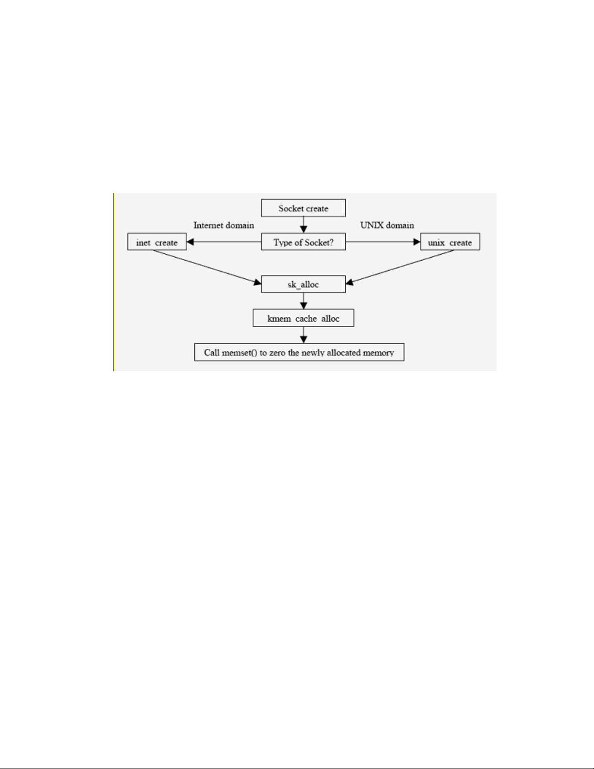
specifying the target address of the server. For an Internet domain socket, the address of the server is its IP
address and its port number.
Sockets are created using the socket() system call. Depending on the type of socket, either UNIX domain
or internet domain, the socket family operations vector invokes either unix_create() or
inet_create().
unix_create() and inet_create() invoke sk_alloc() to allocate the sock structure.
sk_alloc() calls kmem_cache_alloc() to allocate memory, and then zeros the newly allocated memory by
invoking memset(), thus taking care of object reuse issues associated with sockets created by users.
Figure 5-16: Object reuse handling in socket allocation
Calls to bind() and connect() to a UNIX domain socket file requires write access to it. UNIX domain
sockets can be created in the ext3 file system, and therefore may have an ACL associated with them. For a
more detailed description of client-server communication methods and the access control performed by them,
refer to Section 5.12 of this document.
5.4 Network subsystem
The network subsystem allows Linux systems to connect to other systems over a network. It provides a
general purpose framework within which network services are implemented. There are a number of possible
hardware devices that can be connected, and a number of network protocols that can be used. The network
subsystem abstracts both of these implementation details, so user processes and other kernel subsystems can
access the network without knowing the physical devices and the protocol being used.
The various modules in the network subsystem are:
• Network device drivers communicate with the hardware devices. There is one device driver module
for each possible hardware device.
• The device-independent interface module provides a consistent view of all of the hardware devices,
so higher levels in the subsystem do not need specific knowledge of the hardware in use.
• The network protocol modules are responsible for implementing each of the possible network
transport protocols.
69
Page 82

• The protocol-independent interface module provides an interface that is independent of hardware
devices and network protocol. This is the interface module that is used by other kernel subsystems to
access the network without having a dependency on particular protocols or hardware. Finally, the
system call interface module restricts the exported routines that user process can access.
Figure 5-17: Network subsystem and its interaction with other subsystems
Network services include transmission and reception of data, network-independent support for message
routing, and network-independent support for application software. The following subsections present an
overview of the network stack and describe how various layers of the network stack are used to implement
network services.
For more information, see the TCP/IP Tutorial and Technical Overview IBM Redbook by Adolfo, John &
Roland. It is at the http://www.redbooks.ibm.com/abstracts/gg243376.html website.
5.4.1 Overview of the network protocol stack
The network protocol stack, which forms the carrier and pipeline of data from one host to another, is designed
in such a way that one can interact with different layers at desired level. This section describes the movement
of data through these stacked layers.
The physical layer and link layer work hand-in-hand. They consist of the network card and associated device
driver, most often Ethernet but also Token Ring, PPP (for dial-up connections), and others.
The next layer, the network layer, implements the Internet Protocol, which is the basis of all Internet
communications, along with related protocols, including Internet Control Message Protocol (ICMP).
70
Page 83
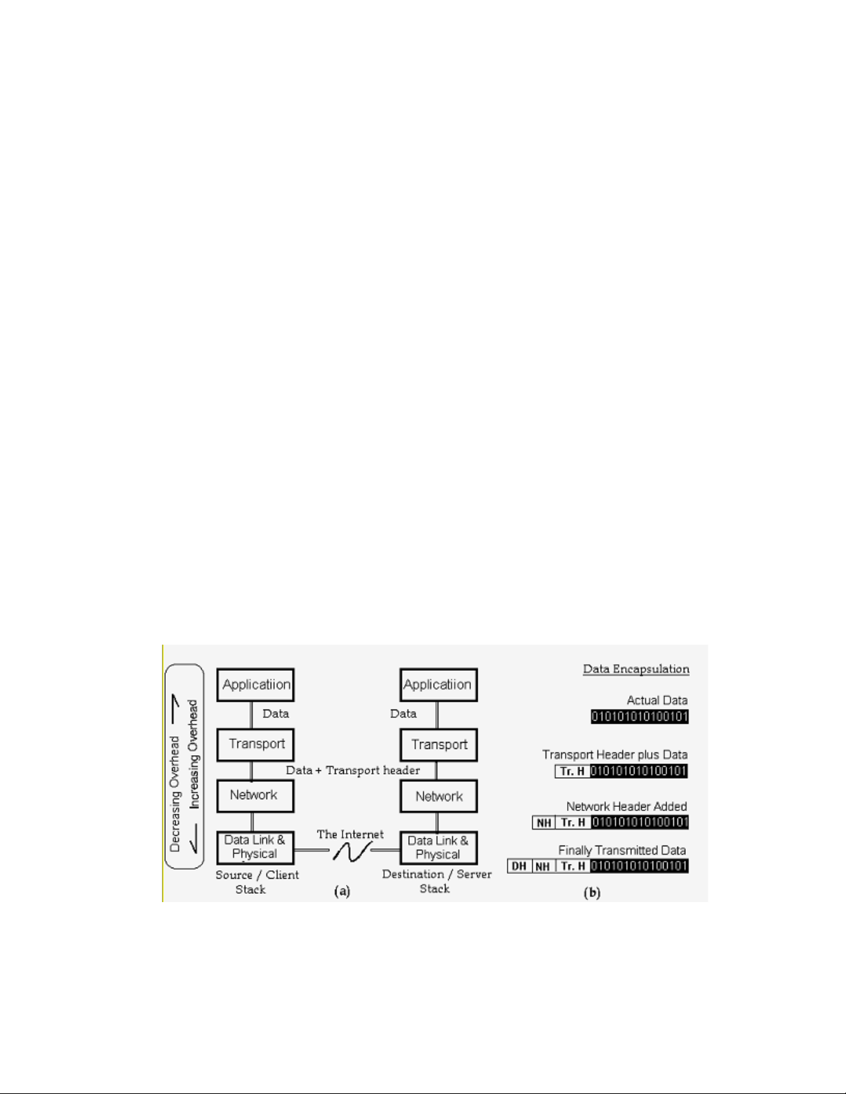
The transport layer consists of the TCP, UDP and similar protocols.
The application layer consists of all the various application clients and servers, such as the Samba file and
print server, the Apache web server, and others. Some of the application-level protocols include Telnet, for
remote login; FTP, for file transfer; and, SMTP, for mail transfer.
Network devices form the bottom layer of the protocol stack. They use a link-layer protocol, usually
Ethernet, to communicate with other devices to send and receive traffic. The interface put up by the network
device driver copies packets from a physical medium, performs some error checks, and then puts up the
packets to the network layer.
Output interfaces receive packets from the network layer, perform error checks, and then send the packets out
over the physical medium. The main functionality of IP is routing:
• It checks incoming packets to see if they are for the host computer or if they need to be forwarded.
• It defragments packets if necessary and delivers them to the transport protocols.
• It has a dynamic database of routes for outgoing packets
• It addresses and fragments them if necessary before sending them down to the link layer.
Transmission Control Protocol (TCP) and User Datagram Protocol (UDP) are the most commonly used
transport layer protocols. UDP simply provides a framework for addressing packets to ports within a
computer, whereas TCP allows more complex connection-based operations such as the recovery of lost
packets, and also traffic management implementations. Both UDP and TCP copy the application packet for
transporting.
Moving up the transport layer, next is the INET (for internet) layer, which forms the intermediate layer
between the transport layer and application sockets. The INET layer implements the sockets owned by the
applications. All socket-specific operations are implemented here.
Each layer of the protocol stack adds a header containing layer-specific information to the data packet. A
header for the network layer might include information such as source and destination addresses. The process
of prepending data with headers is called encapsulation. Figure 5-18 shows how data is encapsulated by
various headers. During decapsulation, the inverse occurs: the layers of the receiving stack extract layerspecific information and accordingly process the encapsulated data. Note that the process of encapsulation
increases the overhead involved in transmitting data.
Figure 5-18: How data travels through the Network protocol stack
71
Page 84

5.4.2 Transport layer protocols
The transport layer protocols supported by the SLES kernel are TCP and UDP.
5.4.2.1 TCP
TCP is a connection-oriented, end-to-end, reliable protocol designed to fit into a layered hierarchy of
protocols that support multi-network applications. TCP provides for reliable IPC between pairs of processes
in host computers attached to distinct but interconnected computer communication networks. TCP is used
along with the Internet Protocol (IP) to send data in the form of message units between computers over the
Internet. While IP takes care of handling the actual delivery of the data, TCP takes care of keeping track of
the individual units of data, or packets, that a message is divided into for efficient routing through the
Internet. For more information about TCP, refer to RFC 793.
5.4.2.2 UDP
UDP is a connectionless protocol that, like TCP, runs on top of IP networks. UDP/IP provides very few error
recovery services, offering instead a direct way to send and receive datagrams over an IP network. It is used
primarily for broadcasting messages over a network. This protocol provides a procedure for application
programs to send messages to other programs with a minimum of protocol mechanism. The protocol is
transaction oriented, and delivery and duplicate protection are not guaranteed. For more information about
UDP, look into RFC 768.
5.4.3 Network layer protocols
The network layer protocols supported by the SLES kernel are IP and ICMP.
5.4.3.1 Internet Protocol Version 4 (IPv4)
IPv4, aka simply IP, is the standard that defines the manner in which the network layers of two hosts interact.
These hosts can be on the same network, or reside on physically distinct heterogeneous networks. In fact, IP
was designed from the very beginning with inter-networking in mind.
IP provides a connectionless, unreliable, best-effort packet delivery service. Its service is called
connectionless because in some ways it resembles the Postal Service. IP packets, like telegrams or mail
messages, are treated independently. Each packet is stamped with the addresses of the receiver and the
sender. Routing decisions are made on a packet-by-packet basis. IP is quite different from connectionoriented and circuit-switched phone systems that explicitly establish a connection between two users before
any conversation, or data exchange, takes place, and maintain a connection for the entire length of exchange.
For information about IP packets, IP addresses, and addressing formats refer to RFC 1883.
5.4.3.2 Internet Protocol Version 6 (IPv6)
The SLES kernel supports Internet Protocol version 6. IPv6 is the standard that defines the manner in which
network layers of two hosts interact, and is an increment to existing IPv4. The TOE is in compliance with
IPv6 source address selection as documented in RFC 3484, and implements several new socket options
(IPV6_RECVPKTINFO, IPV6_PKTINFO, IPV6_RECVHOPOPTS, IPV6_HOPOPTS,
IPV6_RECVDSTOPTS, IPV6_DSTOPTS, IPV6_RTHDRDSTOPTS, IPV6_RECVRTHDR,
IPV6_RTHDR, IPV6_RECVHOPOPTS, IPV6_HOPOPTS, IPV6_RECVTCLASS) and ancillary data in
order to support advanced IPv6 applications including ping, traceroute, routing daemons and others.
72
Page 85

The following section introduces Internet Protocol Version 6 (IPv6). For additional information about
referenced socket options and advanced IPv6 applications, see RFC 3542.
Internet Protocol Version 6 (IPv6) was designed to improve upon and succeed Internet Protocol Version 4
(IPv4).
IPv4 addresses consist of 32 bits. This accounts for about 4 billion available addresses. The growth of the
Internet and the delegation of blocks of these addresses has consumed a large amount of the available address
space. There has been a growing concern that someday we will run out of IPv4 addresses. IPv6 was an
initiative to produce a protocol that improved upon the flaws and limitations of IPv4 and flexible enough to
withstand future growth.
This introduction briefly addresses some of the features of IPv6. For further information, see RFC 2460,
which contains the IPv6 specifications.
5.4.3.2.1 Addressing
IPv6 addresses are comprised of 128 bits, providing for more levels of an addressing hierarchy as well as
space for future growth. A scope field has been added to multicast addresses to make for increased
scalability. The scope identifies whether the packet should be multicast only on the link, site, or globally,
which are levels of the addressing hierarchy.
IPv6 also introduces automatic configuration of IPv6 addresses. It uses the concept of network prefixes,
interface identifiers, and MAC addresses to form and configure the host’s IPv6 address. This IPv6 address is
advertised to local IPv6 routers on the link, thus making for dynamic routing.
5.4.3.2.2 IPv6 Header
Some of the fields and options in an IPv4 header were removed from the IPv6 header. This helped to reduce
the bandwidth required for IPv6, because the addresses themselves are larger. IP options are now placed in
extension headers in IPv6. The extension header format is flexible and therefore will be easier to include
additional options in the future. The extension headers are placed after the IP header and before any upper
layer protocol fields.
RFC 2460 defines the following extension headers for IPv6:
• Hop-by-Hop
• Routing
• Fragment
• Destination Option
• Authentication
• Encapsulating Security Payload
IPv6 Header
73
Page 86
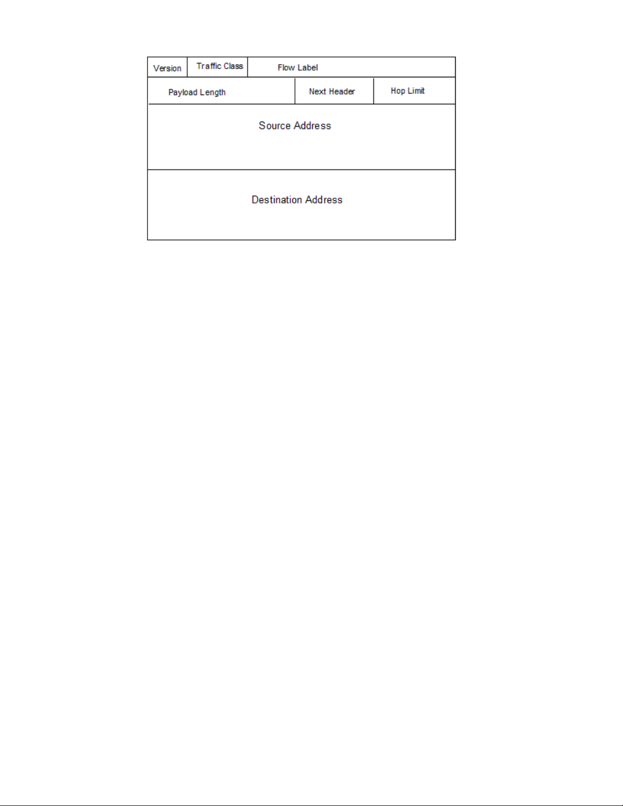
5.4.3.2.3 Flow Labels
The IPv6 header has a field to in which to enter a flow label. This provides the ability to identify packets for
a connection or a traffic stream for special processing.
5.4.3.2.4 Security
The IPv6 specifications mandate IP security. IP security must be included as part of an IPv6 implementation.
IP security provides authentication, data integrity, and data confidentiality to the network through the use of
the Authentication and Encapsulating Security Payload extension headers. IP security is described in more
detail below.
5.4.3.3 Transition between IPv4 and IPv6
IPv4 addresses eventually need to be replaced with IPv6 ones. Due to the size of the Internet, it would be
almost impossible to have a controlled roll out. So, IPv6 specifications incorporate a transition period in
which IPv4 hosts and IPv6 hosts can communicate and reside together. RFC 4213 defines two mechanisms to
accommodate the transition from IPv4 to IPv6, dual stack, and configured tunneling.
In a dual stack, both IPv4 and IPv6 are implemented in the operating system. Linux implements both IPv4
and IPv6.
The second mechanism uses tunnels. The IPv4 network exists while the IPv6 infrastructure is in progress.
IPv6 packets are encapsulated in IPv4 packets and tunneled through IPv4 networks to final destination.
These mechanisms only accommodate the transition period that will be required as IPv6 infrastructure
progresses and replaces IPv4. They allow for a more flexible deployment of IPv6.
5.4.3.4 IP Security (IPsec)
IP Security is an architecture developed for securing packets at the IP layer of the TCPIP protocol stack. It is
comprised of several protocols and services, all working together to provide confidentiality, integrity, and
authentication of IP datagrams.
The phrase data confidentiality refers to data that is secret or private, and that is read or seen only by the
intended recipients. Unsecured packets traveling the internet can be easily intercepted by a network sniffer
program and the contents viewed. The intended recipient would never know the received packet had been
intercepted and read. The IP security architecture provides data confidentiality through encryption
algorithms.
74
Page 87

The phrase data integrity implies that the data received is as it was when sent. It has not been tampered,
altered, or impaired in any way. Data authentication ensures that the sender of the data is really who you
believe it to be. Without data authentication and integrity, someone can intercept a datagram and alter the
contents to reflect something other than what was sent, as well as who sent it. IP Security provides data
authentication and integrity through the use of hash functions in message authentication codes (HMACs).
The encryption algorithms and HMACs require several shared symmetric encryption keys. Thus IP Security
also takes into consideration key management, and the secure exchange of keys through its services.
This introduction briefly describes the collection of protocols and services offered in IP Security.
5.4.3.4.1 Functional Description of IPsec
IP Security provides security at the IP Layer through the use of the AH and ESP protocols. These protocols
operate in transport and tunnel mode.
In transport mode, AH and ESP provide security to the upper-layer protocols of the TCPIP protocol stack
(that is, UDP and TCPIP). Therefore, only part of the IP datagram is protected. Transport mode is usually
used for security between two hosts.
In tunnel mode, AH and ESP provide security to the entire IP datagram. The entire original IP datagram is
encapsulated, and an outer IP header attached. Tunnel mode is usually for security between two gateways
(that is, networks) or between a host and a gateway.
5.4.3.4.1.1 AH Protocol (AH)
The IP Authentication (AH) Header is described in RFC 2402. Besides providing data integrity and
authentication of source, it also protects against replay attacks via the use of a sequence number and replay
window.
The contents of the IP datagram, along with the shared secret key, are hashed, resulting in a digest. This digest
is placed in the AH header, and the AH header is then included in the packet.
Verification occurs when the receiving end removes the AH header, then hashes its shared secret key with the
IP datagram to produce a temporary digest and compare it with the digest in the AH header. If the two digests
are identical, verification has succeeded.
AH Header
When used in transport mode, the AH header is placed before the upper-layer protocol, which it will protect,
and after the IP header and any options for IPv4. In the context of IPv6, according to RFC 2402, AH is
viewed as an end-to-end payload. Therefore, the AH header should appear after the IP headers and hop-byhop, routing, and fragmentation extension headers if present.
An IP Packet with transport mode AH
75
Page 88

In tunnel mode, the entire IP datagram is encapsulated, protecting the entire IP datagram.
An IP Packet with tunnel mode AH
5.4.3.4.1.2 Encapsulating Security Payload Protocol (ESP)
The Encapsulating Security Payload (ESP) header is defined in RFC 2406. Besides data confidentiality, ESP
also provides authentication and integrity as an option. The encrypted datagram is contained in the Data
section of the ESP header. When authentication is also chosen within the ESP protocol, the data is encrypted
first and then authenticated. The authenticated data is placed in the authentication data field. If no
authentication is specified within the ESP protocol, then this field is not used.
ESP Header
When used in transport mode, the ESP header is inserted after the IP header and before any upper-layer
protocols, protecting only the upper layer protocols.
An IP Packet with transport mode ESP
In tunnel mode, the original IP header and any upper-layer protocols are encrypted and then authenticated if
specified.
76
Page 89
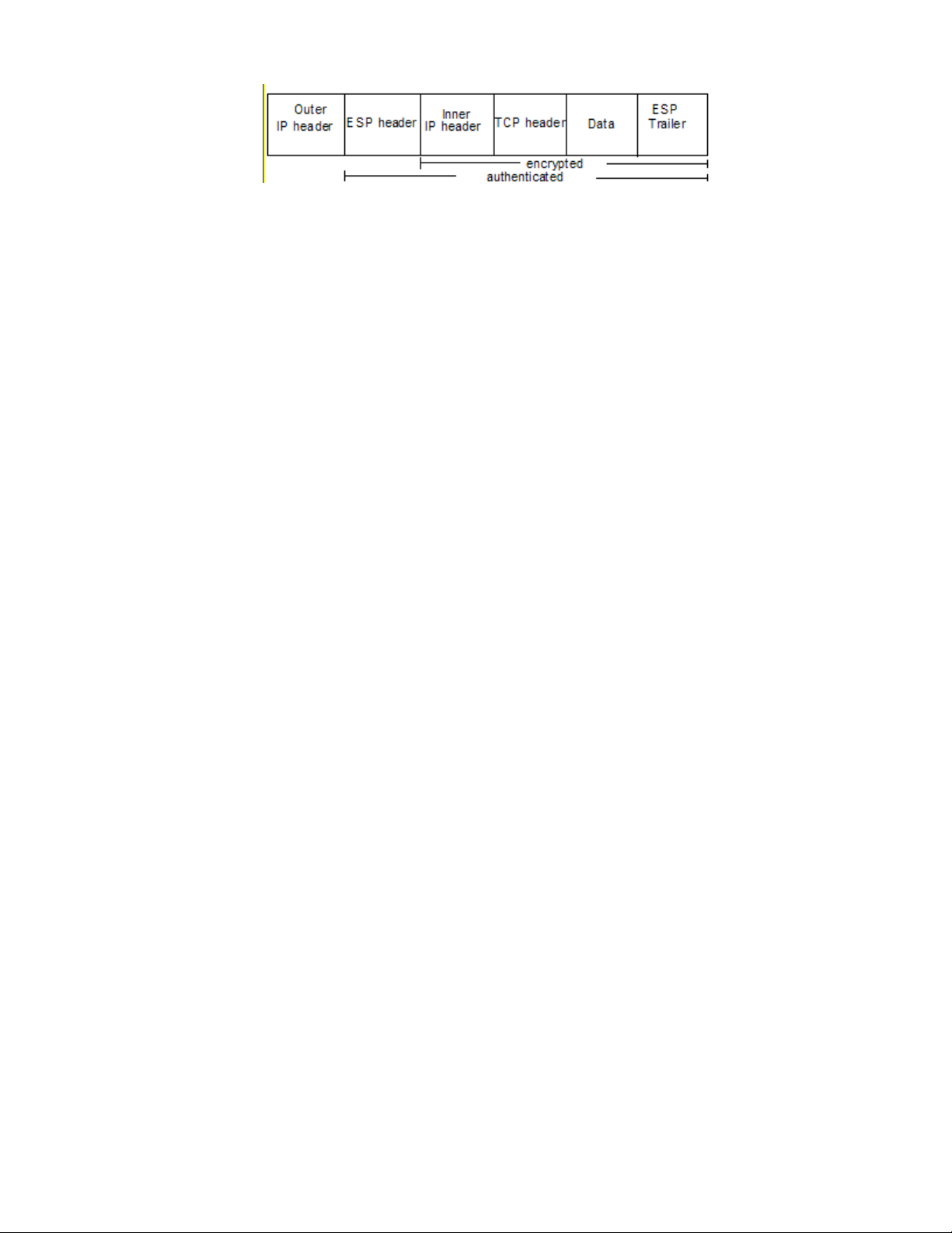
An IP Packet with tunnel mode ESP
5.4.3.4.1.3 Security Associations
RFC2401 defines a Security Association (SA) as a simplex or one-way connection that affords security
services to the traffic it carries. Separate SAs must exist for each direction. IPSec stores the SAs in the
Security Association Database (SAD), which resides in the Linux kernel.
5.4.3.4.1.4 Security Policy
A Security Policy is a general plan that guides the actions taken on an IP datagram. Upon processing an
incoming or outgoing IP datagram, the security policy is consulted to determine what to do with the IP
datagram. One of three actions will occur: the datagram is to be discarded, the datagram is to bypass IPSec
processing, or IPSec processing is to be applied.
If IPSec processing is to be done, the policy will indicate which SA to access in the SAD. This SA will
indicate the keys and service and other information related to the securing of the IP datagram. Security
policies are stored in the Security Policy Database (SPD), which resides in the Linux kernel.
5.4.3.4.1.5 SA, SP, and Key Management
There are services for both manual and automated SA creation and maintenance. Manual management refers
to an administrative user interface that allows for the creation and deletion of policy, SAs, and keys.
Automated SA and key management is done through the IKE protocol.
5.4.3.4.1.6 Internet Key Exchange Protocol (IKE)
The Internet Key Exchange (IKE) protocol is designed so it can be used to negotiate SAs on behalf of any
service, such as IPSec, RIPv2, or OSPF. Each service has a Domain of Interpretation (DOI) document
describing the attributes required to establish an SA. IPSec’s DOI is RFC 2407.
IKE has two basic phases, which it takes from Internet Security Association and Key Management Protocol
(ISAKMP). The first phase establishes an authenticated and secure channel between two remote peers.
During this phase the two peers exchange necessary information and keying material with each other. The
result is an ISAKMP SA for each peer. This ISAKMP SA is then used to set up a secure and authenticated
traffic stream when the two peers wish to negotiate an IPSec SA or an SA for any other service.
5.4.3.4.1.7 Socket API
The PF_KEY API, defined in RFC 2367, is a socket protocol family that allows userspace manual and
automated key management tools to communicate with the kernel.
Linux also has xfrm_user, which makes use of the Netlink API, to communicate with the kernel.
The PF_KEY API defines interfaces for adding, deleting, updating, and retrieving SAs as well as maintaining
the state and lifetime. The API has been extended in the Linux kernel to include SPD management too.
77
Page 90

5.4.3.4.1.8 Cryptographic subsystem
IPSec uses the cryptographic subsystem described in this section. The cryptographic subsystem performs
several cryptographic-related assignments, including Digital Signature Algorithm (DSA) signature
verification, in-kernel key management, arbitrary-precision integer arithmetic, and verification of kernel
modules signatures.
This subsystem was initially designed as a general-purpose mechanism, preserving the design ideas of
simplicity and flexibility, including security-relevant network and file system services such as encrypted files
and file systems, network file system security, strong file system integrity, and other kernel networking
services where cryptography was required.
The ability to enforce cryptographic signatures on loadable modules has a couple of security uses:
• It prevents the kernel from loading corrupted modules
• It makes it difficult for an attacker to install a rootkit on a system
The kernel can be configured for checking or not checking the signatures of modules, so these signatures are
only useful once the system is able to check it. For a signature to be checked and the new module accepted, it
is first necessary that the kernel decrypt the signature with a public key. This public key is contained within
the kernel, and the key must also to have the same checksum.
The in-kernel key management service allows cryptographic keys, authentication tokens, cross-domain user
mappings, and other related security information to be cached in the kernel for the file systems to use other
kernel services.
A special kind of key, called a keyring, which contains a list of keys and support links to others keys, is also
permitted. The keys represent cryptographic data, authentication tokens, keyrings, and similar information.
The in-kernel key management service possesses two special types of keys: the above-mentioned keyring, and
the user key. Userspace programs can directly create and manipulate keys and keyrings through a system call
interface, using three new system calls: add_key(), request_key(), and keyctl(). Services can
register types and search for keys through a kernel interface. There also exists an optional file system in which
the key database can be manipulated and viewed.
For manipulating the key attributes and permissions it is necessary to be the key owner or to have
administrative privileges.
5.4.4 Internet Control Message Protocol (ICMP)
Internet Control Message Protocol (ICMP) is an extension to IP that provides a messaging service. The
purpose of these control messages is to provide feedback about problems in the communication environment.
ICMP messages are sent in following situations:
• When a datagram cannot reach its destination.
• When the gateway does not have the buffering capacity to forward a datagram.
• When the gateway can direct the host to send traffic on a shorter route.
For more information about the ICMP, refer to RFC 792.
5.4.4.1 Link layer protocols
The Address Resolution Protocol (ARP) is the link layer protocol that is supported on the SLES system.
78
Page 91
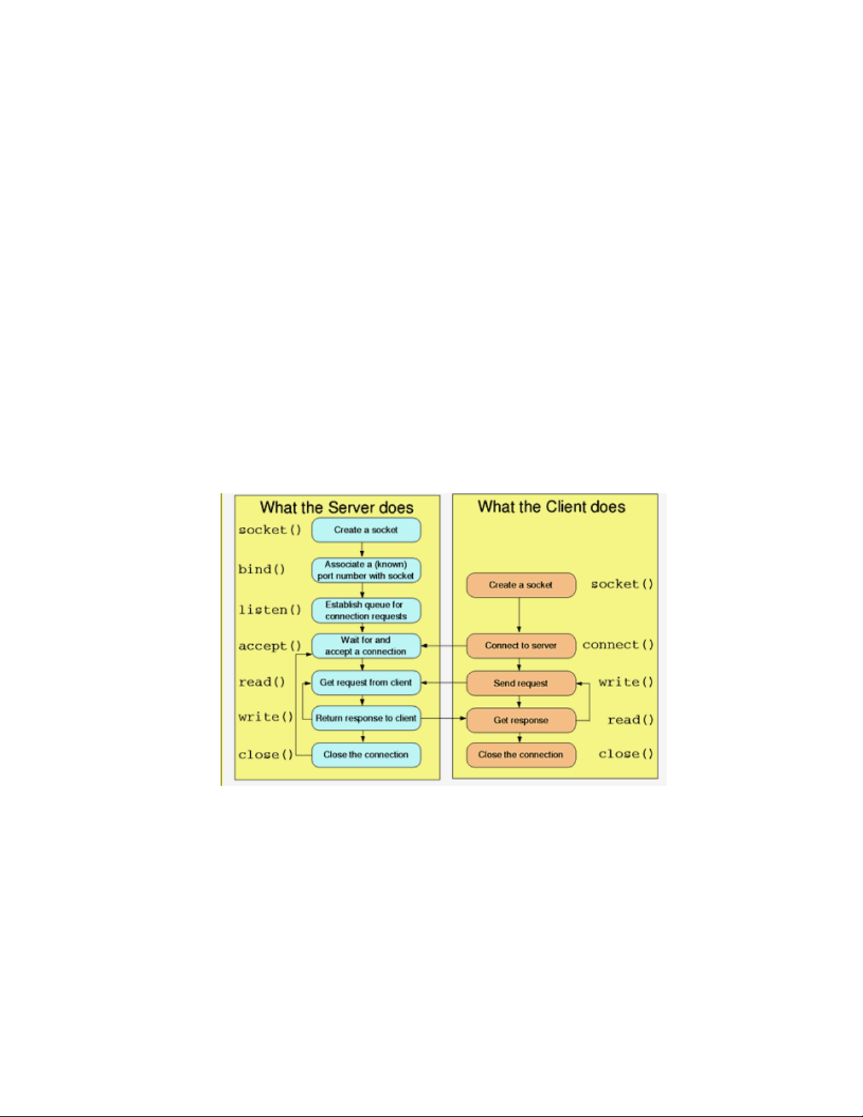
5.4.4.1.1 Address Resolution Protocol (ARP)
Address Resolution Protocol (ARP) is a protocol for mapping an IP address to a physical machine address
that is recognized in the local network. For example, in IP Version 4, the most common level of IP in use
today, an address is 32 bits long. In an Ethernet local area network, however, addresses for attached devices
are 48 bits long. (The physical machine address is also known as a Media Access Control [MAC] address.)
A table, usually called the ARP cache, is used to maintain a correlation between each MAC address and its
corresponding IP address. ARP provides the protocol rules for making this correlation and providing address
conversion in both directions.
There is also Reverse ARP (RARP), which can be used by a host to discover its IP address. In this case, the
host broadcasts its physical address and a RARP server replies with the host's IP address.
5.4.5 Network services interface
The SLES kernel provides networking services through socket interfaces. When sockets are used to establish
a connection between two programs across a network, there is always an asymmetry between the two ends.
One end, on the server, creates a communication endpoint at a known address, and waits passively for
connection requests. The other end, on the client, creates its own communication endpoint and actively
connects to the server endpoint at its known address.
Figure 5-19 shows the steps taken by both server and client to establish a connection, along with the system
calls used at each stage.
Figure 5-19: Server and client operations using socket interface
A communication channel is established using ports and sockets, which are needed to determine which local
process at a given host actually communicates with which process, on which remote host, and using which
protocol. A port is a 16-bit number, used by the host-to-host protocol to identify to which higher-level
protocol or application program it must deliver incoming messages. Sockets, which are described in Section
5.3.5, are communications end points. Ports and sockets provide a way to uniquely and uniformly identify
connections and the program and hosts that are engaged in them.
79
Page 92

The following subsections describe access control and object reuse handling associated with establishing a
communications channel.
5.4.5.1 socket()
socket() creates an endpoint of communication using the desired protocol type. Object reuse handling
during socket creation is described in Section 5.3.5. socket() may perform additional access control
checks by calling the security_socket_create() and security_socket_post_create()
LSM hooks, but the SLES kernel does not use these LSM hooks.
5.4.5.2 bind()
bind() associates a name (address) to a socket that was created with the socket system call. It is necessary
to assign an address to a socket before it can accept connections. Depending on the domain type of the
socket, the bind function gets diverted to the domain-specific bind function.
Figure 5-20: bind() function for internet domain TCP socket
If the port number being associated with a socket is below PROT_SOCK (defined at compile time as 1024),
then inet_bind() ensures that the calling process possesses the CAP_NET_BIND_SERVICE capability.
On the TOE, the CAP_NET_BIND_SERVICE capability maps to a uid of zero.
80
Page 93

Figure 5-21: bind() function for UNIX domain TCP socket
Similarly, for UNIX domain sockets, bind() invokes unix_bind(). unix_bind() creates an entry in
the regular ext3 file system space. This process of creating an entry for a socket in the regular file system
space has to undergo all file system access control restrictions. The socket exists in the regular ext3 file
system space, and honors DAC policies of the ext3 file system. bind() may perform additional access
control checks by calling the security_socket_bind() LSM hook, but the SLES kernel does not use
this LSM hook. bind() does not create any data objects that are accessible to users, so there are no object
reuse issues to handle.
5.4.5.3 listen()
listen() indicates a willingness to accept incoming connections on a particular socket. A queue limit for
the number of incoming connections is specified with listen(). Other than checking the queue limit,
listen() does not perform DAC. It may perform additional access control checks by calling the
security_socket_listen() LSM hook but the SLES kernel does not use this hook. listen()
does not create any data objects that are accessible to users, so there are no object reuse issues to handle.
Only TCP sockets support the listen() system call.
5.4.5.4 accept()
accept() accepts a connection on a socket. accept() does not perform any access control. accept()
does not create any data objects that are accessible to users and therefore there are no object reuse issues to
handle. Only TCP sockets support accept() system call.
5.4.5.5 connect()
connect() initiates a connection on a socket. The socket must be listening for connections; otherwise, the
system call returns an error. Depending upon the type of the socket (stream for TCP or datagram for UDP),
connect() invokes the appropriate domain type specific connection function. connect() does not
perform DAC. It may perform additional access control checks by calling the
security_socket_connect() LSM hook, but the SLES kernel does not use this hook. connect()
does not create any data objects that are accessible to users, so there are no object reuse issues to handle.
81
Page 94
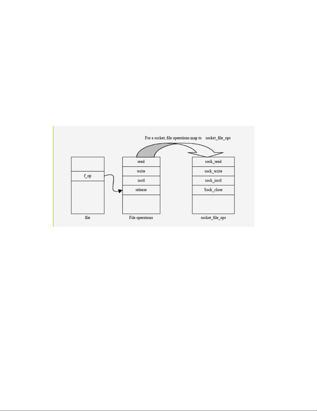
5.4.5.6 Generic calls
read(), write() and close(): read(), write() and close() are generic I/O system calls
that operate on a file descriptor. Depending on the type of object, whether regular file, directory, or socket,
appropriate object-specific functions are invoked.
5.4.5.7 Access control
DAC mediation is performed at bind() time. The socket(), bind(), connect(), listen(),
accept(), sendmsg(), recvmsg(), getsockname(), getpeername(), getsockopt(),
setsockopt(), and shutdown() syscalls may perform additional access control checks by calling
LSM hooks but the SLES kernel does not do this. read(), write(), and close() operations on
sockets do not perform any access control.
Figure 5-22: Mapping read, write and close calls for sockets
5.5 Memory management
The memory management subsystem is responsible for controlling process access to the hardware memory
resources. This is accomplished through a hardware memory-management system that provides a mapping
between process memory references and the machine's physical memory. The memory management
subsystem maintains this mapping on a per-process basis, so two processes can access the same virtual
memory address and actually use different physical memory locations. In addition, the memory management
subsystem supports swapping; it moves unused memory pages to persistent storage to allow the computer to
support more virtual memory than there is physical memory.
The memory management subsystem is composed of three modules:
• The architecture-specific module presents a virtual interface to the memory management hardware.
• The architecture-independent management module performs all of the per-process mapping and
virtual memory swapping. This module is responsible for determining which memory pages will be
evicted when there is a page fault; there is no separate policy module, since it is not expected that this
policy will need to change.
82
Page 95
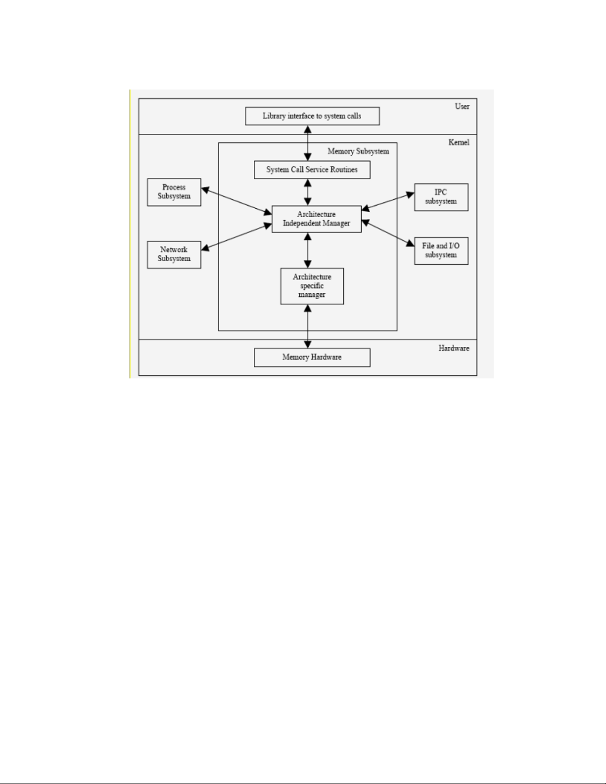
• A system call interface is provided to provide restricted access to user processes. This interface
allows user processes to allocate and free storage, and also to perform memory-mapped file I/O.
Figure 5-23: Memory subsystem and its interaction with other subsystems
This section highlights the implementation of the System Architecture requirements of a) allowing the kernel
software to protect its own memory resources and b) isolating memory resources of one process from those of
another, while allowing controlled sharing of memory resources between user processes.
This section is divided into five subsections. The first subsection, Four-Level Page Tables discuss recent
changes to the Linux page table implementation. The second subsection, Memory Addressing, illustrates the
SLES kernel’s memory addressing scheme and highlights how segmentation and paging are used to prevent
unauthorized access to a memory address. The third subsection, Kernel Memory Management, describes how
the kernel allocates dynamic memory for its own use, and highlights how the kernel takes care of object reuse
while allocating new page frames. The fourth subsection, Process Address Space, describes how a process
views dynamic memory and what the different components of a process’s address space are. The forth
subsection also highlights how the kernel enforces access control with memory regions and handles object
reuse with demand paging. The final subsection, Symmetric Multiprocessing and Synchronization, describes
various SMP synchronization techniques used by the SLES kernel.
Because implementations of a portion of the memory management subsystem are dependent on the
underlying hardware architecture, the following subsections identify and describe, where appropriate, how the
hardware-dependent part of the memory management subsystem is implemented for the System x, System p,
System z, and eServer 326 line of servers, which are all part of the TOE.
83
Page 96

5.5.1 Four-Level Page Tables
Before the current implementation of four-level page tables, the kernel implemented a three-level page table
structure for all architectures. The three-level page table structure that previously existed was constituted,
from top to bottom, for the page global directory (PGD), page middle directory (PMD), and PTE.
In this implementation, the PMD is absent on systems that only present two-level page tables, so the kernel
was able to recognize all architectures as if they possessed three-level page tables.
Figure 5-24: Previous three-level page-tables architecture
The new page table structure actually implemented includes a new level, called PUD, immediately below the
top-level PGD directory. The PGD remains the top-level directory, and the PUD only exists on architectures
that are using four-level page tables. The PMD and PTE levels present the same function as in previous
kernels’ implementations. Each of the levels existent in a page table hierarchy is indexed with a subset of the
bits in the virtual address of interest.
84
Page 97

Figure 5-25: New page-table implementation: the four-level page-table
architecture
The creation and insertion of a new level, the PUD level, immediately below the top-level PGD directory
aims to maintain portability and transparency once all architectures have an active PGD at the top of
hierarchy and an active PTE at the bottom. The PMD and PUD levels are only used in architectures that need
them. These levels are optimized on systems that do not use them.
It is a less intrusive way to update the page tables’ hierarchy, since it can be ignored by systems not using
these levels. This is the same characteristic maintained by the kernel in the previous implementation of threelevel page table architecture.
With this new implementation, architectures that use four-level page tables can have a virtual address space
covering 128 TB of memory, far more than the 512 GB of virtual address space available with the old one.
5.5.2 Memory addressing
The main memory of a computer is a collection of cells that store data and machine instructions. Each cell is
uniquely identified by a number or its memory address.
As part of executing a program, a processor accesses memory to fetch instructions or to fetch and store data.
Addresses used by the program are virtual addresses. The memory management subsystem provides
translation from virtual to real addresses. The translation process, in addition to computing valid memory
locations, also performs access checks to ensure that a process is not attempting an unauthorized access.
Memory addressing is highly dependent on the processor architecture. The memory addressing for System x,
System p, System z, and eServer 326 systems is described in the following sections.
5.5.2.1 System x
SLES provides enhanced handling of user process and kernel virtual address space for Intel x86-compatible
systems (32 bit x86 systems only). Traditionally, 32-bit x86 systems had a fixed 4 GB virtual address space,
which was allocated so the kernel had 1 GB and each user process 3 GB (referred to as the 3-1 split). This
allocation has become restrictive because of the growing physical memory sizes. It is possible to configure a
4-4 split, where each user process and the kernel are allocated 4 GB of virtual address space. There are two
important benefits to this new feature:
85
Page 98

The larger kernel virtual address space allows the system to manage more physical memory. Up to 64 GB of
main memory is supported by SLES on x86-compatible systems.
The larger user virtual address space allows applications to use approximately 30% more memory (3.7—3.8
GB), improving performance for applications that take advantage of the feature. This means that x86compatible systems can be expected to have a longer life-span and better performance. FIXME unique?
Figure 5-26: System x virtual addressing space
This section briefly explains the System x memory addressing scheme. The three kinds of addresses on
System x are:
• Logical address: A logical address is included in the machine language instructions to specify the
address of an operand or an instruction. It consists of a segment and an offset (or displacement) that
denotes the distance from the start of the segment to the actual address.
• Linear address: A single 32-bit unsigned integer that can address up to 4 GB. That is, up to
4,294,967,296 memory cells.
• Physical address: A 32-bit unsigned integer that addresses memory cells in physical memory chips.
In order to access a particular memory location, the CPU uses its segmentation unit to transform a logical
address into a linear address, and then a paging unit to transform a linear address into a physical address (see
Figure 5-27).
Figure 5-27: Logical Address Translation
86
Page 99

5.5.2.1.1 Segmentation
The segmentation unit translates a logical address into a linear address. A logical address consists of two
parts: a 16 bit segment identifier called the segment selector, and a 32-bit offset. For quick retrieval of the
segment selector, the processor provides six segmentation registers whose purpose is to hold segment
selectors. Three of these segmentation registers have specific purpose. For example, the code segment (cs)
register points to a memory segment that contains program instructions. The cs register also includes a 2-bit
field that specifies the Current Privilege Level (CPL) of the CPU. The CPL value of 0 denotes the highest
privilege level, corresponding to the kernel mode; the CPL value of 3 denotes the lowest privilege level,
corresponding to the user mode.
Each segment is represented by an 8-byte Segment Descriptor that describes the segment characteristics.
Segment Descriptors are stored in either the Global Descriptor Table (GDT) or the Local Descriptor Table
(LDT). The system has one GDT, but may create an LDT for a process if it needs to create additional
segments besides those stored in the GDT. The GDT is accessed through the GDTR processor register, while
the LDT is accessed through the LDTR processor register.
From the perspective of hardware security access, both GDT and LDT are equivalent. Segment descriptors
are accessed through their 16-bit segment selectors. A segment descriptor contains information, such as
segment length, granularity for expressing segment size, and segment type, which indicates whether the
segment holds code or data. Segment descriptors also contain a 2-bit Descriptor Privilege Level (DPL),
which restricts access to the segment. The DPL represents the minimal CPU privilege level required for
accessing the segment. Thus, a segment with a DPL of 0 is accessible only when the CPL is 0.
Figure 5-28 schematically describes access control as enforced by memory segmentation.
Figure 5-28: Access control through segmentation
87
Page 100
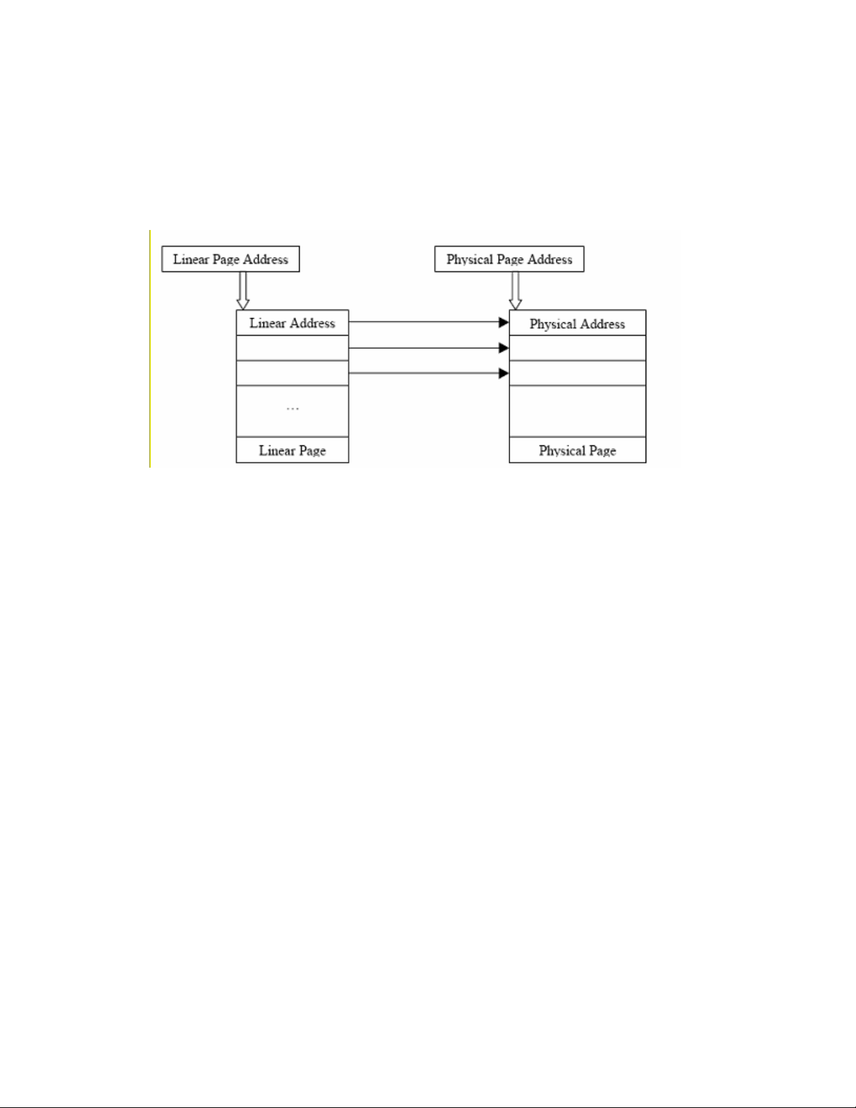
5.5.2.1.2 Paging
The paging unit translates linear addresses into physical addresses. It checks the requested access type against
the access rights of the linear address. Linear addresses are grouped in fixed-length intervals called pages.
To allow the kernel to specify the physical address and access rights of a page instead of addresses and access
rights of all the linear addresses in the page, continuous linear addresses within a page are mapped to
continuous physical addresses.
Figure 5-29: Contiguous linear addresses map to contiguous physical
addresses
The paging unit sees all RAM as partitioned into fixed-length page frames. A page frame is a container for a
page. A page is a block of data that can be stored in a page frame in memory or on disk. Data structures that
map linear addresses to physical addresses are called page tables. Page tables are stored in memory and are
initialized by the kernel when the system is started.
The System x supports two types of paging: regular paging and extended paging. The regular paging unit
handles 4 KB pages, and the extended paging unit handles 4 MB pages. Extended paging is enabled by setting
the Page Size flag of a Page Directory Entry.
In regular paging, 32 bits of linear address are divided into three fields:
• Directory: The most significant 10 bits represents directory.
• Table: The intermediate 10 bits represents table.
• Offset: The least significant 12 bits represents offset.
88
 Loading...