

Page 1

Nortel 10 Gigabit Uplink Ethernet Switch
Module for IBM BladeCenter
Installation Guide
Page 2

Page 3

Nortel 10 Gigabit Uplink Ethernet Switch
Module for IBM BladeCenter
Installation Guide
Page 4

Note:
Before using this information and the product it supports, read the general information
in Appendix A, “IBM Statement of Limited Warranty Z125-4753-08 04/2004,” on page 43,
and Appendix B, “Notices,” on page 67.
First Edition (May 2006)
© Copyright International Business Machines Corporation 2006. All rights reserved.
US Government Users Restricted Rights – Use, duplication or disclosure restricted by
GSA ADP Schedule Contract with IBM Corp.
Page 5

Contents
Safety . . . . . . . . . . . . . . . . . . . . . . . .v
Chapter 1. Introduction . . . . . . . . . . . . . . . . . .1
Specifications . . . . . . . . . . . . . . . . . . . . . .2
Related documentation . . . . . . . . . . . . . . . . . . .2
Notices and statements used in this document . . . . . . . . . . .3
Major components of the GbE switch module . . . . . . . . . . .4
Information panel overview . . . . . . . . . . . . . . . .5
LEDs . . . . . . . . . . . . . . . . . . . . . . . .6
Chapter 2. Installing and removing the GbE switch module . . . . .9
Installation guidelines . . . . . . . . . . . . . . . . . . .9
System reliability considerations . . . . . . . . . . . . . .10
Handling static-sensitive devices . . . . . . . . . . . . . .10
Installing the GbE switch module . . . . . . . . . . . . . . .10
Removing the GbE switch module . . . . . . . . . . . . . . .12
Chapter 3. Installing and removing options . . . . . . . . . . .15
Handling an XFP or SFP module . . . . . . . . . . . . . . .15
Installing an XFP module . . . . . . . . . . . . . . . . . .16
Removing an XFP module . . . . . . . . . . . . . . . . .18
Installing an SFP module . . . . . . . . . . . . . . . . . .18
Removing an SFP module . . . . . . . . . . . . . . . . .19
Chapter 4. Cabling . . . . . . . . . . . . . . . . . . .21
Connecting the serial console cable . . . . . . . . . . . . . .21
Disconnecting the serial console cable . . . . . . . . . . . . .21
Connecting the CX4 module cable . . . . . . . . . . . . . . .21
Disconnecting a CX4 module cable . . . . . . . . . . . . . .22
Connecting an XFP module cable . . . . . . . . . . . . . . .22
Disconnecting the XFP module cable . . . . . . . . . . . . . .24
Connecting the SFP module cable . . . . . . . . . . . . . . .24
Disconnecting an SFP module cable . . . . . . . . . . . . . .24
Chapter 5. Configuring the GbE switch module . . . . . . . . .25
Establishing a TCP/IP session using the management module . . . . .27
Enabling management over external ports . . . . . . . . . . . .28
Configuring the GbE switch module using Telnet . . . . . . . . . .28
Connecting to the GbE switch module . . . . . . . . . . . .29
Accessing the main menu . . . . . . . . . . . . . . . .29
Configuring the GbE switch module using the serial-port interface . . . .29
Configuring the GbE switch module using the switch-module Browser
Based Interface . . . . . . . . . . . . . . . . . . . .30
© Copyright IBM Corp. 2006 iii
Page 6

Initial configuration . . . . . . . . . . . . . . . . . . .31
Logging in to the GbE switch module . . . . . . . . . . . . .32
Chapter 6. Updating the software . . . . . . . . . . . . . .33
Determining the level of GbE switch module software . . . . . . . .33
Obtaining the latest level of switch software . . . . . . . . . . .33
Upgrading the GbE switch module software . . . . . . . . . . .34
Resetting and restarting the GbE switch module . . . . . . . . . .35
Chapter 7. Parts listing . . . . . . . . . . . . . . . . . .37
Chapter 8. Solving problems . . . . . . . . . . . . . . . .39
Running POST . . . . . . . . . . . . . . . . . . . . .39
POST errors . . . . . . . . . . . . . . . . . . . . . .39
Chapter 9. Getting help and technical assistance . . . . . . . . .41
Before you call . . . . . . . . . . . . . . . . . . . . .41
Using the documentation . . . . . . . . . . . . . . . . . .41
Getting help and information from the World Wide Web . . . . . . .42
Software service and support . . . . . . . . . . . . . . . .42
Hardware service and support . . . . . . . . . . . . . . . .42
Appendix A. IBM Statement of Limited Warranty Z125-4753-08 04/2004 43
Part 1 - General Terms . . . . . . . . . . . . . . . . . . .43
Part 2 - Country-unique Terms . . . . . . . . . . . . . . . .47
Part 3 - Warranty Information . . . . . . . . . . . . . . . .62
Appendix B. Notices . . . . . . . . . . . . . . . . . . .67
Trademarks . . . . . . . . . . . . . . . . . . . . . .68
Important notes . . . . . . . . . . . . . . . . . . . . .69
Product recycling and disposal . . . . . . . . . . . . . . . .69
Battery return program . . . . . . . . . . . . . . . . . .71
Electronic emission notices . . . . . . . . . . . . . . . . .71
Federal Communications Commission (FCC) statement . . . . . . .71
Industry Canada Class A emission compliance statement . . . . . .72
Australia and New Zealand Class A statement . . . . . . . . .72
United Kingdom telecommunications safety requirement . . . . . .72
European Union EMC Directive conformance statement . . . . . .72
Taiwanese Class A warning statement . . . . . . . . . . . .73
Chinese Class A warning statement . . . . . . . . . . . . .73
Japanese Voluntary Control Council for Interference (VCCI) statement 73
Index . . . . . . . . . . . . . . . . . . . . . . . .75
iv Nortel 10 Gigabit Uplink Ethernet Switch Module: Installation Guide
Page 7

Safety
Before installing this product, read the Safety Information.
Antes de instalar este produto, leia as Informações de Segurança.
Pred instalací tohoto produktu si prectete prírucku bezpecnostních instrukcí.
Læs sikkerhedsforskrifterne, før du installerer dette produkt.
Lees voordat u dit product installeert eerst de veiligheidsvoorschriften.
Ennen kuin asennat tämän tuotteen, lue turvaohjeet kohdasta Safety
Information.
Avant d’installer ce produit, lisez les consignes de sécurité.
Vor der Installation dieses Produkts die Sicherheitshinweise lesen.
Prima di installare questo prodotto, leggere le Informazioni sulla Sicurezza.
Les sikkerhetsinformasjonen (Safety Information) før du installerer dette
produktet.
© Copyright IBM Corp. 2006 v
Page 8

Antes de instalar este produto, leia as Informações sobre Segurança.
Antes de instalar este producto, lea la información de seguridad.
Läs säkerhetsinformationen innan du installerar den här produkten.
vi Nortel 10 Gigabit Uplink Ethernet Switch Module: Installation Guide
Page 9

Statement 1:
DANGER
Electrical
current from power, telephone, and communication cables is
hazardous.
To avoid a shock hazard:
v Do not connect or disconnect any cables or perform installation,
maintenance, or reconfiguration of this product during an electrical
storm.
v Connect all power cords to a properly wired and grounded electrical
outlet.
v Connect to properly wired outlets any equipment that will be attached
to this product.
v When possible, use one hand only to connect or disconnect signal
cables.
v Never turn on any equipment when there is evidence of fire, water, or
structural damage.
v Disconnect the attached power cords, telecommunications systems,
networks, and modems before you open the device covers, unless
instructed otherwise in the installation and configuration procedures.
v Connect and disconnect cables as described in the following table
when installing, moving, or opening covers on this product or attached
devices.
To Connect: To Disconnect:
1. Turn everything OFF.
2. First, attach all cables to devices.
3. Attach signal cables to connectors.
4. Attach power cords to outlet.
5. Turn device ON.
1. Turn everything OFF.
2. First, remove power cords from outlet.
3. Remove signal cables from connectors.
4. Remove all cables from devices.
Safety vii
Page 10

viii Nortel 10 Gigabit Uplink Ethernet Switch Module: Installation Guide
Page 11
Chapter 1. Introduction
®
The Nortel 10 Gigabit Uplink Ethernet Switch Module for IBM
BladeCenter
is an I/O module that is installed into a BladeCenter unit. This Installation
Guide contains information about installing and configuring the Nortel 10
Gigabit Uplink Ethernet Switch Module for IBM BladeCenter.
Note: Throughout this document, the Nortel 10 Gb Uplink Ethernet Switch
Module for IBM BladeCenter is referred to as the GbE switch module.
For installation details, see Chapter 2, “Installing and removing the GbE switch
module,” on page 9 and Chapter 3, “Installing and removing options,” on page
15. For additional information, see the instructions in the BladeCenter
documentation.
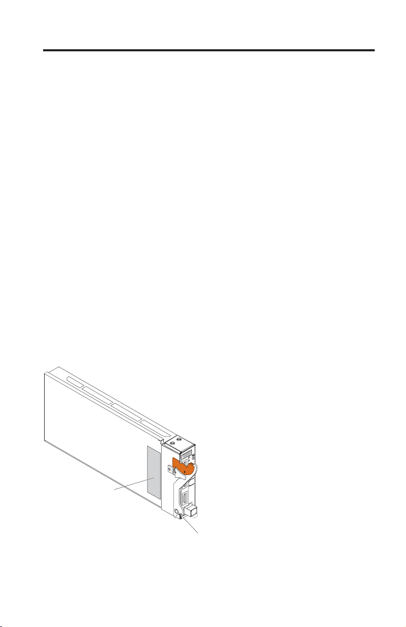
The product name and serial number are on the identification label on the GbE
switch module. Yo u will need this information when you register your GbE
switch module with IBM. The media access control (MAC) address is on a
separate label on the information panel under the external Ethernet port
connectors.
See the following illustration for the locations of the identification label and the
MAC address label.
®
Note: The illustrations in this document might differ from your hardware.
RS232
LINK
1
TX/RX
LINK
2
TX/RX
LINK
3
TX/RX
LINK
4
Product name
and serial
number label
© Copyright IBM Corp. 2006 1
TX/RX
3
Media access control
(MAC) address label
Page 12

You can obtain up-to-date information about the BladeCenter and other IBM
server products at http://www.ibm.com/support/. Record information about
your GbE switch in the following table:
Product name Nortel 10 Gigabit Uplink Ethernet Switch Module for IBM
BladeCenter
Serial number _________________________________________________
Media access
control (MAC)
_________________________________________________
address
Specifications
This section provides a summary of the specifications of the GbE switch
module. For more information about the features, see the Nortel 10 Gigabit
Uplink Ethernet Switch Module for IBM BladeCenter Application Guide available at
http://www.ibm.com/support/.
Related documentation
In addition to this document, the following related documentation is provided
in PDF format on the Documentation CD that comes with your BladeCenter
unit or available at http://www.ibm.com/support/.
v Safety Information
This document is in Portable Document Format (PDF) on the Documentation
CD that comes with your GbE switch module and is provided at
http://www.ibm.com/support/. It contains translated caution and danger
statements. Each caution and danger statement that appears in the
documentation has a number that you can use to locate the corresponding
statement in your language in the Safety Information document.
v Nortel 10 Gb Uplink Ethernet Switch Module for IBM BladeCenter Application
Guide
This application document contains software configuration information for
the GbE switch module.
v Nortel 10 Gb Uplink Ethernet Switch Module for IBM BladeCenter Browser Based
Interface Quick Guide
This Quick Guide contains information about software configuration using
the Nortel Browser Based Interface.
v Nortel 10 Gb Uplink Ethernet Switch Module for IBM BladeCenter Command
Reference
This Command Reference document contains information to configure your
GbE switch module using the command line interface (CLI).
2 Nortel 10 Gigabit Uplink Ethernet Switch Module: Installation Guide
Page 13

v User’s Guide that comes with your management module.
This document contains information for configuring your GbE switch
module using the management-module user interface.
v IBM BladeCenter Management Module Command Line Reference Guide
This document contains information for configuring your GbE switch
module using the management-module CLI.
In addition to reviewing these documents, make sure to review the Planning
and Installation Guide for your BladeCenter unit type for information to help
you prepare for system installation and configuration at
http://www.ibm.com/support/.
For BladeCenter units with four I/O-module bays, you must also install an
Ethernet-I/O card (also known as an Ethernet expansion card) in the blade
server to support the GbE switch module in I/O-module bays 3 or 4. For
information about the types of compatible I/O-expansion cards for the blade
servers, see the documentation for your BladeCenter unit.
Notices and statements used in this document
The caution and danger statements that appear in this document are also in
the multilingual Safety Information document, which is on the Documentation
CD that comes with your BladeCenter unit. Each statement is numbered for
reference to the corresponding statement in the Safety Information document.
The following types of notices and statements are used in this document:
v Note: These notices provide important tips, guidance, or advice.
v Important: These notices provide information or advice that might help you
avoid inconvenient or problem situations.
v Attention: These notices indicate possible damage to programs, devices, or
data. An attention notice is placed just before the instruction or situation in
which damage could occur.
v Caution: These statements indicate situations that can be potentially
hazardous to you. A caution statement is placed just before the description
of a potentially hazardous procedure step or situation.
v Danger: These statements indicate situations that can be potentially lethal or
extremely hazardous to you. A danger statement is placed just before the
description of a potentially lethal or extremely hazardous procedure step or
situation.
Chapter 1. Introducing the Gigabit Ethernet switch module 3
Page 14
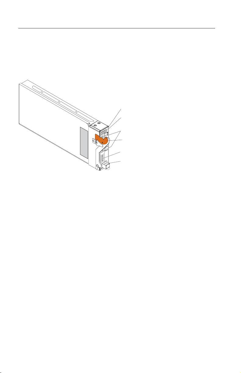
Major components of the GbE switch module
Orange on the release latch on the GbE switch module indicates that the device
can be hot-swapped, which means that you can install or remove this
component while the BladeCenter unit power is turned on. See Chapter 3,
“Installing and removing options,” on page 15 for more information about
installing and removing a GbE switch module.
Information panel
RS232 serial
console port
RS232
LINK
1
TX/RX
LINK
2
TX/RX
LINK
3
TX/RX
LINK
4
TX/RX
3
CX4 ports
Release latch
XFP port
SFP port
4 Nortel 10 Gigabit Uplink Ethernet Switch Module: Installation Guide
Page 15
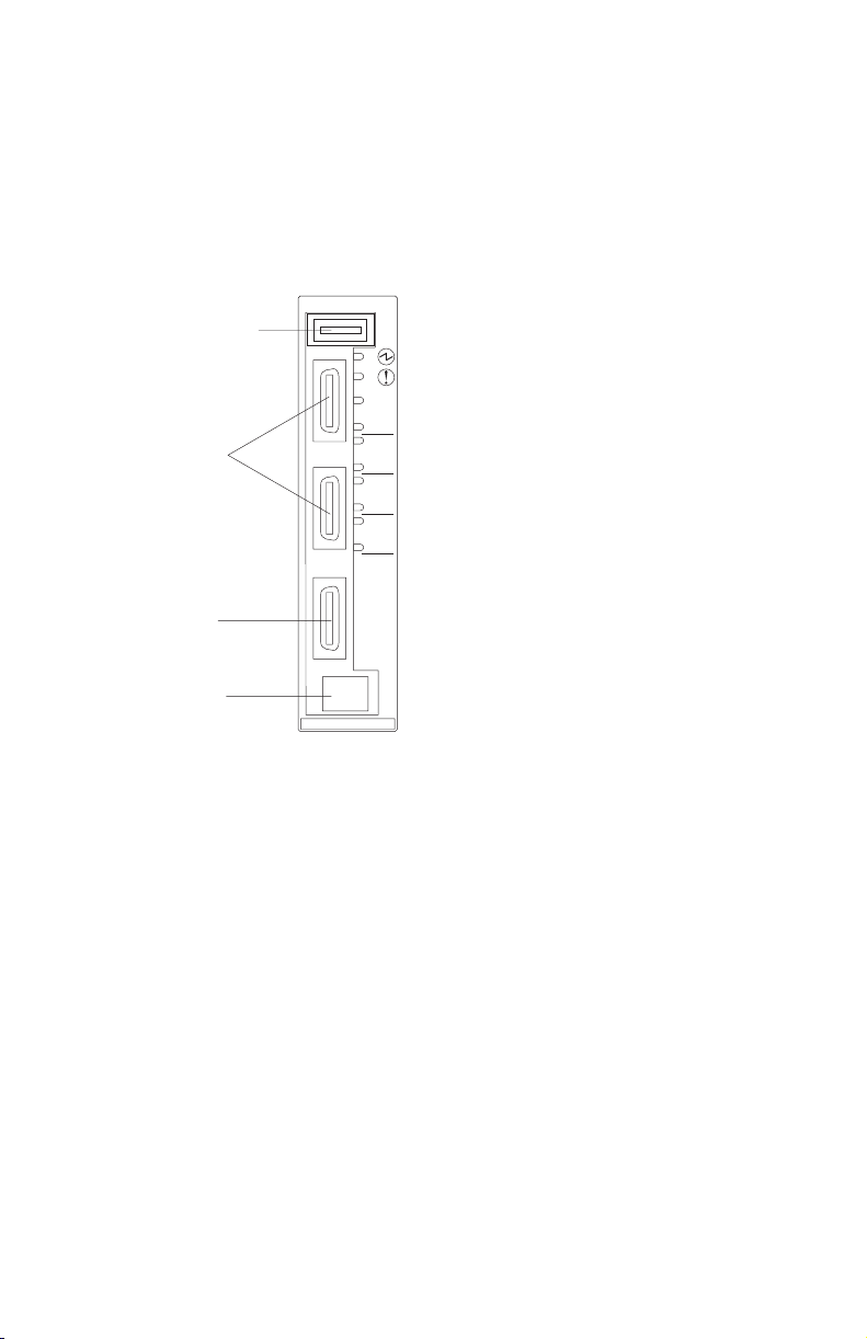
Information panel overview
The information panel provides LEDs, which display the status of the GbE
switch module and the network (see “LEDs” on page 6) and external
connections for the GbE switch module.
The following illustration shows the information panel of the GbE switch
module.
RS232 serial
port
CX 4 port
RS232
LINK
1
TX/RX
LINK
2
TX/RX
LINK
3
TX/RX
LINK
4
TX/RX
XFP module
SFP module slot
3
4
Chapter 1. Introducing the Gigabit Ethernet switch module 5
Page 16
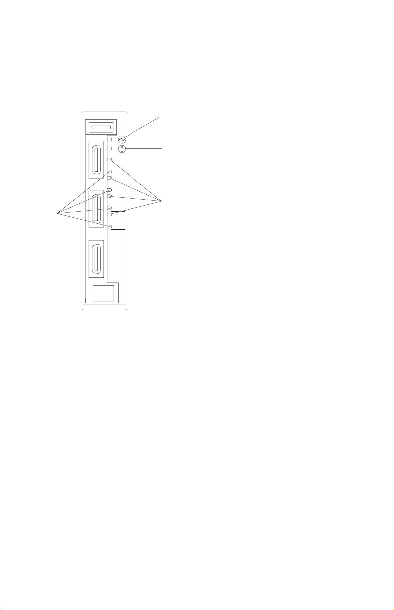
LEDs
In addition to the OK and GbE switch module error LEDs on the information
panel, each external port on the GbE switch module has a TX/RX LED and a
LINK LED. The following illustration shows the LEDs on the GbE switch
module. A description of each LED follows the illustration.
RS232
OK
Switch module
TX/RX
LINK
1
TX/RX
LINK
2
TX/RX
LINK
3
TX/RX
LINK
4
TX/RX
error
Link
3
4
Note: An amber LED is lit when a system error or event has occurred. To
identify the error or event, check the management module event log. For
additional information, see Chapter 8, “Solving problems,” on page 39.
OK: When this green status LED is lit, it indicates that the GbE switch module
has passed the power-on self-test (POST) with no critical faults and is
operational.
Switch module error: When this amber status LED is lit, it indicates that the
GbE switch module has a fault. If the GbE switch module fails the POST or
detects an operational fault, this LED is lit.
Note: When this LED is lit, the system-error LED on the BladeCenter unit is
also lit.
Link: When this green link status LED is lit on a port, it indicates that there is
a connection (or link) to a device on that connector.
TX/RX: When this green activity LED flashes on a connector, it indicates that
data is being transmitted or received (that is, activity is occurring) between
6 Nortel 10 Gigabit Uplink Ethernet Switch Module: Installation Guide
Page 17

that port and another device on the network link. The flashing frequency is
proportional to the amount of traffic on the network link.
Chapter 1. Introducing the Gigabit Ethernet switch module 7
Page 18

8 Nortel 10 Gigabit Uplink Ethernet Switch Module: Installation Guide
Page 19

Chapter 2. Installing and removing the GbE switch module
See the Installation and User’s Guide for your BladeCenter unit for information
about the I/O-module bay locations in the BladeCenter unit and specific
requirements for installing I/O modules in your BladeCenter unit.
Attention: To maintain proper system cooling, each I/O-module bay must
contain either a module or a filler module; each blade bay must contain either
a blade or a filler blade.
The BladeCenter unit supports one hot-plug GbE switch module, in
I/O-module bay 1. The GbE switch module in I/O-module bays 1 and 2 are
for the integrated Ethernet controllers in the appropriate blade servers. Yo u
might want to install GbE switch modules in other I/O-module bays of the
BladeCenter unit when additional Ethernet controllers are installed or
activated.
For additional information about the location of the GbE switch module, the
network interface requirements, and expansion options, see the documentation
for your BladeCenter unit and your blade servers.
Installation guidelines
Before you begin to install the GbE switch module in the BladeCenter unit,
read the following information:
v Read the safety information beginning on page v and the guidelines in
“Handling static-sensitive devices” on page 10, and read the safety
statements in the BladeCenter unit documents.
v Orange on the release latch on the GbE switch module indicates that the
device can be hot-swapped, which means that you can install or remove this
component while the BladeCenter unit is on. See the instructions in this
chapter for more information about installing or removing hot-swap or
hot-plug components.
v You do not have to turn off the BladeCenter unit to install or replace any of
the hot-swap modules on the rear of the unit.
v If you plan to install a GbE switch module in I/O-module bay 3 or 4 of the
BladeCenter unit, you must also install an I/O expansion card in the blade
server to support the GbE switch modules in these bays.
© Copyright IBM Corp. 2006 9
Page 20

System reliability considerations
To help ensure proper cooling and system reliability, make sure that:
v Each of the I/O-module bays on the rear of the BladeCenter unit has either a
module or a filler module installed.
v A removed hot-swap module or blade server is replaced with another
module or filler module within 1 minute of removal.
Handling static-sensitive devices
Attention: Static electricity can damage electronic devices. To avoid damage,
keep static-sensitive devices in their static-protective packages until you are
ready to install them.
To reduce the possibility of electrostatic discharge, observe the following
precautions:
v Limit your movement. Movement can cause static electricity to build up
around you.
v Handle the device carefully, holding it by its edges or its frame.
v Do not touch solder joints, pins, or exposed printed circuitry.
v Do not leave the device where others can handle and damage it.
v While the device is still in its static-protective package, touch it to any
unpainted metal surface of the BladeCenter unit or any unpainted metal
surface on any other grounded rack component for at least 2 seconds. (This
drains static electricity from the package and from your body.)
v Remove the device from its package and install it directly into the
BladeCenter unit without setting it down. If it is necessary to set down the
device, put it back into its static-protective package. Do not place the device
on the BladeCenter unit or on a metal surface.
v Take additional care when handling devices during cold weather. Heating
reduces indoor humidity and increases static electricity.
Installing the GbE switch module
To install the GbE switch module, complete the following steps:
1. Read the safety information beginning on page v and “Installation
guidelines” on page 9.
2. Remove the acoustic-attenuation module, if one is installed, from the rear
of the BladeCenter unit. For more information, see the documentation that
came with the BladeCenter unit.
3. Select an I/O-module bay in which to install the GbE switch module.
Note: For details about I/O-module bay requirements, see the
BladeCenter documents for your BladeCenter unit.
10 Nortel 10 Gigabit Uplink Ethernet Switch Module: Installation Guide
Page 21
4. Remove the filler module from the selected bay. Store the filler module for
future use.
5. If you have not already done so, touch the static-protective package that
contains the GbE switch module to any unpainted metal surface of the
BladeCenter unit or any unpainted metal surface on any other grounded
rack-component for at least 2 seconds.
6. Remove the GbE switch module from its static-protective package.
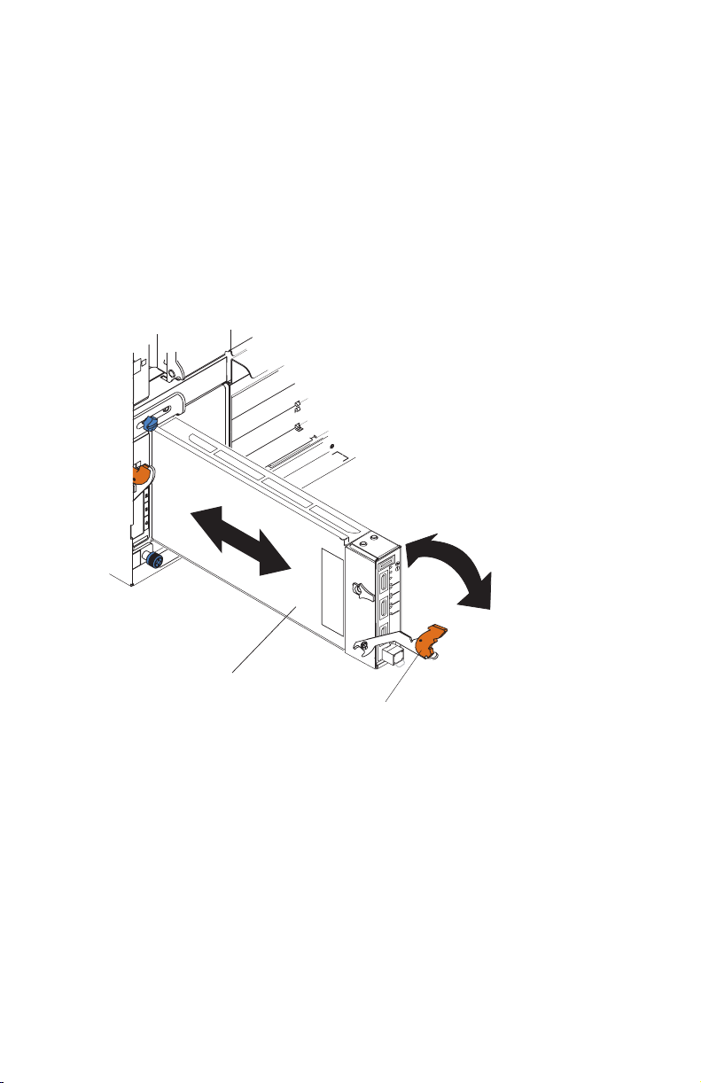
7. Make sure that the release latch on the GbE switch module is in the open
position (perpendicular to the module).
8. Slide the GbE switch module into the applicable I/O-module bay until it
stops.
RS232
LINK
1
TX/RX
LINK
2
TX/RX
LINK
3
TX/RX
LINK
4
TX/RX
3
I/O module
9. Push the release latch on the front of the GbE switch module to the closed
Release latch
position. After you insert and lock the GbE switch module, it is turned on,
and the power-on self-test (POST) runs to verify that the GbE switch
module is operating correctly. The POST results are displayed by the
status LEDs.
10. Make sure that the LEDs on the GbE switch module indicate that it is
operating correctly. Make sure that the OK LED on each GbE switch
module is lit. See “LEDs” on page 6 for a description of the operation of
these LEDs.
11. If you have other GbE switch modules to install, do so now; otherwise, go
to step 12.
Chapter 2. Installing and removing the GbE switch module 11
Page 22
12. Attach any cables that are required by the GbE switch module, see
Chapter 4, “Cabling,” on page 21. For the locations of the connectors on
the BladeCenter unit, see the documents that came with the BladeCenter
unit.
13. Replace the acoustic-attenuation module, if you removed it in Step 2.
Removing the GbE switch module
To remove the GbE switch module, complete the following steps:
1. Read the safety information beginning on page v and “Installation
guidelines” on page 9.
2. Remove the acoustic-attenuation module, if one is installed, from the rear
of the BladeCenter unit. For more information, see the documents that
came with the BladeCenter unit.
3. Disconnect any cables from the GbE switch module that you are removing.
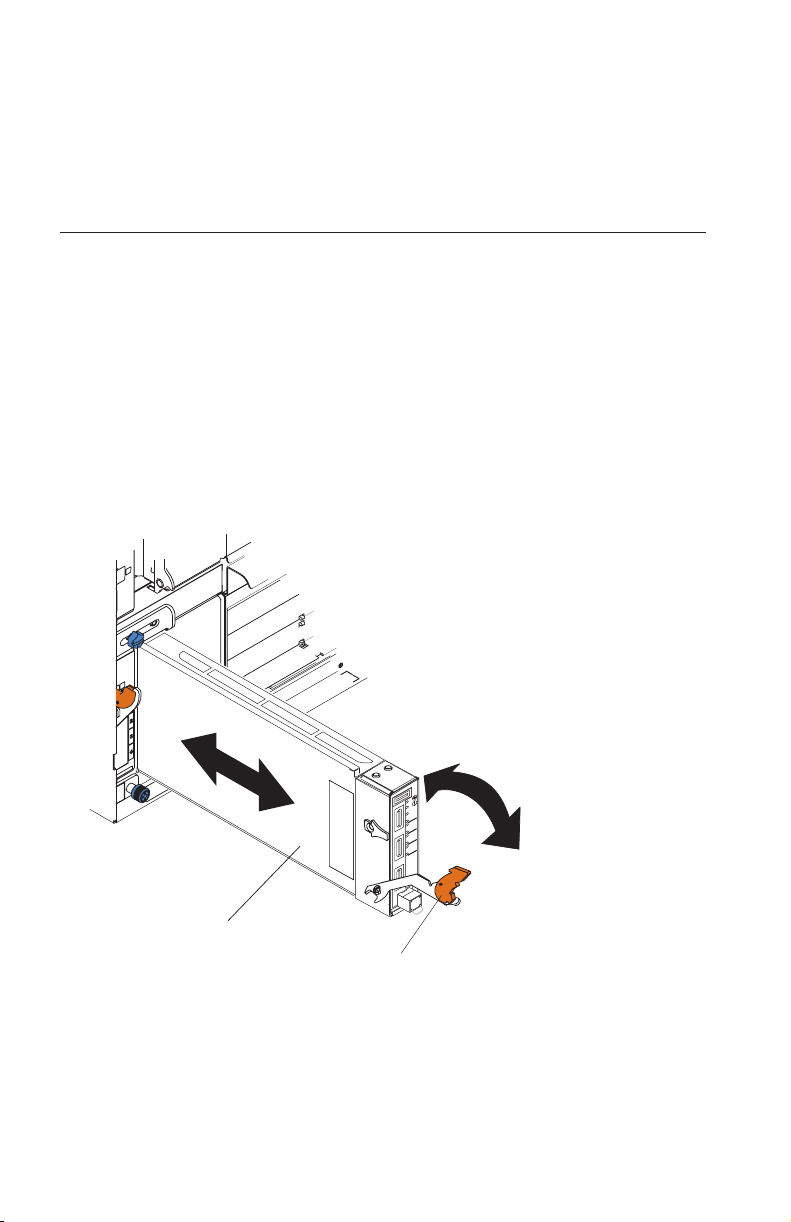
4. Pull the release latch toward the bottom of the GbE switch module as
shown in the following illustration. The module moves out of the bay
approximately 0.64 cm (0.25 inch).
RS232
LINK
1
TX/RX
LINK
2
TX/RX
LINK
3
TX/RX
LINK
4
TX/RX
3
I/O module
Release latch
5. Slide the GbE switch module out of the bay and set it aside.
6. Place either another GbE switch module or a filler module in the bay
within 1 minute.
7. If you placed another GbE switch module in the bay, reconnect any cables
that you disconnected. For more information about cabling the 10GbE
switch module, see Chapter 4, “Cabling,” on page 21.
12 Nortel 10 Gigabit Uplink Ethernet Switch Module: Installation Guide
Page 23

8. Replace the acoustic-attenuation module, if you removed it in Step 2 on
page 10.
Chapter 2. Installing and removing the GbE switch module 13
Page 24

14 Nortel 10 Gigabit Uplink Ethernet Switch Module: Installation Guide
Page 25

Chapter 3. Installing and removing options
The GbE switch module supports the 10 Gigabit small-form-factor pluggable
(XFP) module and the small-form-factor pluggable (SFP) module. The XFP
module is a laser product that is used to convert electrical signals to optical
signals. The SFP module provides an RJ-45 port for external connections. The
GbE switch module ships with the SFP module installed.
For additional information about the location of the GbE switch module, the
network interface requirements, and expansion options, see the documentation
for your BladeCenter unit.
Handling an XFP or SFP module
Before installing an XFP or SFP module, read the following information:
v The module housing of the XFP and SFP has an integral guide key that is
designed to prevent you from inserting the modules incorrectly.
v Use minimal pressure when you insert the modules into the ports. Forcing
the modules into the ports can cause damage to the module or the module
port.
v You can insert or remove the modules while the BladeCenter is turned-on.
v You must first insert the modules into the ports before you can connect the
cables.
v You must remove the cables from the modules before removing the modules
from the GbE switch module.
Statement 3:
CAUTION:
When laser products (such as CD-ROMs, DVD drives, fiber optic devices,
or transmitters) are installed, note the following:
– Do not remove the covers. Removing the covers of the laser product
could result in exposure to hazardous laser radiation. There are no
serviceable parts inside the device.
– Use of controls or adjustments or performance of procedures other than
those specified herein might result in hazardous radiation exposure.
© Copyright IBM Corp. 2006 15
Page 26
DANGER
Some
laser products contain an embedded Class 3A or Class 3B laser
diode. Note the following.
Laser radiation when open. Do not stare into the beam, do not view
directly with optical instruments, and avoid direct exposure to the
beam.
Class 1 Laser Product
Laser Klasse 1
Laser Klass 1
Luokan 1 Laserlaite
Appareil A Laser de Classe 1
`
Installing an XFP module
The XFP module provides two fiber-optic cable connectors for connecting to
external ports. To install an XFP module, complete the following steps:
1. Read the information in “Safety” on page v.
2. Remove the XFP module from its static-protective package.
Statement 3:
CAUTION:
When laser products (such as CD-ROMs, DVD drives, fiber optic devices,
or transmitters) are installed, note the following:
v Do not remove the covers. Removing the covers of the laser product
could result in exposure to hazardous laser radiation. There are no
serviceable parts inside the device.
v Use of controls or adjustments or performance of procedures other
than those specified herein might result in hazardous radiation
exposure.
16 Nortel 10 Gigabit Uplink Ethernet Switch Module: Installation Guide
Page 27
RS232
TX/RX
LINK
1
TX/RX
LINK
2
TX/RX
LINK
3
TX/RX
LINK
4
3
DANGER
Some
laser products contain an embedded Class 3A or Class 3B laser
diode. Note the following.
Laser radiation when open. Do not stare into the beam, do not view
directly with optical instruments, and avoid direct exposure to the
beam.
Class 1 Laser Product
Laser Klasse 1
Laser Klass 1
Luokan 1 Laserlaite
Appareil A Laser de Classe 1
`
3. Remove the protective cap from the XFP module and store it in a safe
place.
4. Insert the XFP module into the XFP module port until it clicks into place.
Note: The illustrations in this document might differ from your device.
RS232
LINK
1
TX/RX
LINK
2
TX/RX
LINK
3
TX/RX
LINK
4
TX/RX
3
Attention: To avoid damage to the cable or the XFP module, make sure
that you do not connect the fiber-optic cable before you install the XFP
module.
Chapter 3. Installing and removing options 17
Page 28

5. Connect the fiber-optic cable (see “Connecting an XFP module cable” on
page 22 and any cables you disconnected earlier).
Removing an XFP module
To remove an XFP module, complete the following steps:
1. Read the safety information beginning on page v and “Installation
guidelines” on page 9.
2. Read the information in “Handling an XFP or SFP module” on page 15.
3. Remove the fiber-optic cable from the XFP module that you want to
replace. For more information about removing the cable, see “Disconnecting
the XFP module cable” on page 24.
Attention: To avoid damage to the cable or the XFP module, make sure
that you disconnect the fiber-optic cable before you remove the XFP module.
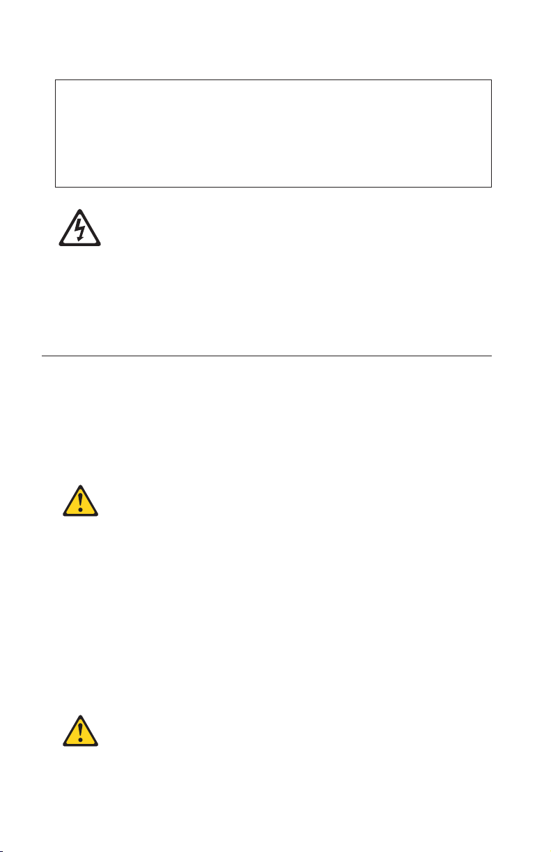
4. Unlock the XFP module by pulling the wire tab straight out as shown in
the following illustration.
Note: The illustrations in this document might differ from your device.
Wire
tab
Protective
cap
XFP
module
5. Grasp the wire tab on the XFP module and pull it out of the port.
6. Replace the protective cap on the XFP module.
7. Place the XFP module into a static-protective package.
Installing an SFP module
The SFP module provides a RJ-45 connector for external connections. To install
an SFP module, complete the following steps:
1. Read the information in “Safety” on page v.
2. Remove the SFP module from its static-protective package.
3. Lock the SFP module by pulling the wire tab straight out and down as
shown in the following illustration.
18 Nortel 10 Gigabit Uplink Ethernet Switch Module: Installation Guide
Page 29

Note: The illustrations in this document might differ from your device.
Wire tab
SFP module
4. Insert the SFP module into the SFP module port until it clicks into place.
Note: The illustrations in this document might differ from your device.
RS232
LINK
1
TX/RX
LINK
2
TX/RX
LINK
3
TX/RX
LINK
4
TX/RX
3
SFP module
Attention: To avoid damage to the cable or the SFP module, make sure
that you do not connect the fiber-optic cable before you install the SFP
module.
5. Connect the RJ-45 cable and any cables you disconnected earlier. For more
information about connecting the cable, see “Connecting the SFP module
cable” on page 24.
Removing an SFP module
To remove an SFP module from the GbE switch module, complete the
following steps:
1. Read the safety information beginning on page v and “Installation
guidelines” on page 9.
Chapter 3. Installing and removing options 19
Page 30

2. Read the information in “Handling an XFP or SFP module” on page 15.
3. Remove any cables attached to the SFP module.
4. Unlock the SFP module by pulling the wire tab straight out and up as
shown in the following illustration.
Wire tab
SFP module
5. Grasp the wire tab on the SFP module and pull it out of the SFP module
port.
6. Place the SFP module into a static-protective package.
20 Nortel 10 Gigabit Uplink Ethernet Switch Module: Installation Guide
Page 31

Chapter 4. Cabling
This chapter describes how to cable the GbE switch module and its options.
Connecting the serial console cable
To connect the serial console cable to the GbE switch module, connect the
serial cable to the RS-232 serial console port of the GbE switch module and the
other end of the cable to the console device.
Note: The illustrations in this document might differ from your device.
RS232 cable
RS232
LINK
1
TX/RX
LINK
2
TX/RX
LINK
3
TX/RX
LINK
4
TX/RX
3
Disconnecting the serial console cable
To disconnect the serial console cable, gently pull the cable from the module.
Connecting the CX4 module cable
To connect a CX4 module cable to the GbE switch module, complete the
following steps:
1. Remove the cable from its packaging.
2. Connect the CX4 connector to the CX4 port by orienting the cable connector
to the module connector, then push the connector into the module until it
clicks into place.
© Copyright IBM Corp. 2006 21
Page 32

RS232
LINK
1
TX/RX
LINK
2
TX/RX
LINK
3
TX/RX
LINK
4
TX/RX
3
3. Check the LEDs on the GbE switch module. When the GbE switch module
is operating correctly, the green link LED is lit. For information about the
status of the switch module LEDs, see “LEDs” on page 6.
Disconnecting a CX4 module cable
To disconnect a CX4 cable, grasp the blue release tab on the cable connector
and firmly pull it out of the module.
Connecting an XFP module cable
Attention: To avoid damage to the fiber-optic cables, follow these guidelines:
v Do not route the cable along a folding cable-management arm.
v When attaching the cable to a device on slide rails, leave enough slack in the
cable so that it does not bend to a radius of less than 38 mm (1.5 in.) when
the device is extended or become pinched when the device is retracted.
v Route the cable away from places where it can be snagged by other devices
in the rack.
v Do not overtighten the cable straps or bend the cables to a radius of less
than 38 mm (1.5 in.).
v Do not put excess weight on the cable at the connection point. Make sure
that the cable is well supported.
To connect the XFP module cable, complete the following steps:
Note: The illustrations in this document might differ slightly from your
hardware.
22 Nortel 10 Gigabit Uplink Ethernet Switch Module: Installation Guide
Page 33

1. Remove the protective caps from the end of the fiber-optic cable.
Fiber-optic
cable
Protective cap
2. Gently slide the fiber-optic cable into the XFP module until it clicks into
place.
RS232
LINK
1
TX/RX
LINK
2
TX/RX
LINK
3
TX/RX
LINK
4
TX/RX
3
3. Check the LEDs on the GbE switch module. When the GbE switch module
is operating correctly, the green link LED is lit. For information about the
status of the switch module LEDs, see “LEDs” on page 6.
Chapter 4. Cabling 23
Page 34

Disconnecting the XFP module cable
To disconnect an XFP module cable, complete the following steps:
1. Squeeze the release tabs and gently pull the fiber-optic cable from the XFP
module.
2. Replace the protective caps on the ends of the fiber-optic cable.
Connecting the SFP module cable
To connect the SFP module cable, slide an RJ-45 cable into the SFP module
connector until it clicks.
RS232
LINK
1
TX/RX
LINK
2
TX/RX
LINK
3
TX/RX
LINK
4
TX/RX
3
Disconnecting an SFP module cable
To remove an RJ-45 cable from an SFP module, gently grasp the tab on the
connector of the cable and pull the cable out of the SFP module.
24 Nortel 10 Gigabit Uplink Ethernet Switch Module: Installation Guide
Page 35

Chapter 5. Configuring the GbE switch module
The GbE switch module has an internal Ethernet path to the management
module, four external Ethernet ports, and a serial console port. The GbE switch
module supports two remote-access modes for management through Ethernet
connections. Yo u can select the mode that is best suited for your BladeCenter
environment.
v Default mode: The default mode uses the internal path to the management
module only. In this mode, the remote-access link to the management
console must be attached to the Ethernet connector on the management
module. The IP addresses and SNMP parameters of the GbE switch modules
can be automatically assigned by the IBM Director BladeCenter Deployment
wizard (when available), or you must assign them through the BladeCenter
Management and Configuration Program. This mode enables the system
administrator to provide a secure LAN for management of the BladeCenter
subsystems that is separate from the data network. See “Establishing a
TCP/IP session using the management module” on page 27 for more
information.
v Remote management mode: The system administrator can choose to enable
remote management of the GbE switch module through the four external
ports, instead of or in addition to access through the management module.
This mode can be enabled only through the management module
configuration interface. When this mode is enabled, the external Ethernet
ports will support both management traffic and BladeCenter application
data traffic.
This mode enables the use of additional GbE switch module IP addresses on
different IP subnets than the management modules. This is useful when the
GbE switch modules are to be managed and controlled as part of the overall
network infrastructure, while secure management of other BladeCenter
subsystems is maintained through the management module. See “Enabling
management over external ports” on page 28 for additional instructions
about configuring the GbE switch module for this mode of operation.
The RS-232 console port provides an alternative path to manage and configure
the switch for local access.
Important:
v Before you configure the GbE switch module, make sure that the
management modules in the BladeCenter unit are correctly configured. See
the Installation and User’s Guide for your BladeCenter unit type for more
information about configuring the GbE switch module.
© Copyright IBM Corp. 2006 25
Page 36

v The default IP address of the GbE switch module is 192.168.70.127,
192.168.70.128, 192.168.70.129, or 192.168.70.130, depending on the switch
module bay where it is installed.
v If you change the IP address of the GbE switch module and restart the
BladeCenter unit, the GbE switch module maintains this new IP address as
its default value.
v The management module and the GbE switch module can communicate
with each other only if they are on the same IP subnet.
v When you use the management-module We b interface to update the
switch-module configuration, the management-module firmware saves the
new configuration in its internal nonvolatile random-access memory
(NVRAM). If the GbE switch module restarts, the management module
applies the saved configuration to the GbE switch module.
If the GbE switch module restarts and the management module cannot
apply the saved configuration, the GbE switch module defaults to using the
configuration that it had previously saved. If the IP subnet address of the
GbE switch module does not match the IP subnet address of the
management module, you can no longer manage the GbE switch module
from the management module.
v For switch communication with a remote management station, such as the
IBM Director server, through the management-module external Ethernet
port, the switch-module internal-network interface and the
management-module internal and external interfaces must be on the same IP
subnet.
the documentation listed in the “Related documentation” on page 2 for
See
specific details about configuring the GbE switch module and preparing for
system installation.
26 Nortel 10 Gigabit Uplink Ethernet Switch Module: Installation Guide
Page 37

Establishing a TCP/IP session using the management module
To establish a TCP/IP session for the GbE switch module using the
management module, complete the following steps:
1. Log on to the management module as described in the User’s Guide or
Command Line Interface Reference Guide for your management module. If
necessary, obtain the IP address of the management module from your
system administrator. The management-module window opens.
Note: The User ID and Password fields are case-sensitive. Type your
information in uppercase letters only. To maintain system security,
change your password after you log on for the first time. The default
User ID is USERID and the default password is PASSW0RD (where the O
in password is a zero).
2. From the I/O Module Tasks menu, click Configuration.
3. In the I/O Module Configuration section, click the bay number that
corresponds to the location of the GbE switch module that you installed.
4. In the IP address field in the New Static IP Configuration section, type the
new TCP/IP address of the GbE switch module; then, click Save.
Note: The management module does not check for invalid IP addresses.
5. Click Advanced Configuration. You can now start a We b session or a
Telnet session.
The Web interface and the Telnet program provide different ways to access the
same internal-switching software and configure it.
v If your system application requires that you use the Web interface program,
see “Configuring the GbE switch module using the switch-module Browser
Based Interface” on page 30 for additional information.
v If your system application requires that you use the Telnet program, see
“Configuring the GbE switch module using Telnet” on page 28 for
additional information.
Chapter 5. Configuring the GbE switch module 27
Page 38

Enabling management over external ports
To access and manage your GbE switch module through external interfaces,
you must enable the external ports and the ability to manage them. Use the
information in the following table to configure your ports.
External management External ports Description
Disabled Disabled The switch must be managed
Disabled Enabled The switch must be managed
Enabled Disabled The switch can be managed
Enabled Enabled The switch can be managed
through the management
module. No traffic is allowed
on external ports.
through the management
module. Data traffic is allowed
on external ports.
through the management
module or a blade server. No
traffic is allowed on external
ports.
through the management
module, a blade server, or a
management station connected
through an external port. Data
traffic is allowed on external
ports.
To enable management over external ports, complete the following steps:
1. Log on to the management module as described in the User’s Guide or
Command Line Interface Reference Guide for your management module. If
necessary, obtain the IP address of the management module from your
system administrator. The management-module window opens.
2. Click I/O Module Tasks → Configuration and click the bay number that
corresponds to the location of the GbE switch module that you installed.
3. Click Advanced Configuration and ensure that the external management is
enabled.
4. Click I/O Module Tasks → Admin/Power/Restart and ensure that the ports
are enabled for the GbE switch module that you installed.
Configuring the GbE switch module using Telnet
Your GbE switch module supports a command line interface (CLI) that you can
use to configure and control the GbE switch module over the network using
the Telnet program. You can use the CLI to perform many basic network
management functions. In addition, you can configure the GbE switch module
28 Nortel 10 Gigabit Uplink Ethernet Switch Module: Installation Guide
Page 39

for management using an SNMP-based network management system. The
following sections describe how to use the Telnet interface to access the GbE
switch module, change its settings, and monitor its operation.
Connecting to the GbE switch module
If you know the IP address for your GbE switch module and you have an
existing network connection, you can use the Telnet program from an external
management station or the management module to access and control the GbE
switch module. The management station and your GbE switch module must be
on the same IP subnet. If you need to obtain the IP address for your GbE
switch module or establish a network connection, contact your system or
network administrator. Be sure to use the correct IP address in the required
command, as specified in “Accessing the main menu.”
Accessing the main menu
To connect to the GbE switch module using Telnet, complete the following
steps:
1. From a DOS command line prompt, type telnet x and press Enter.
where x is the IP address for your GbE switch module.
2. If you do not have an assigned initial password, in the Password field, type
the default password (admin) and press Enter.
Important:
The apply command changes the currently active configuration. If
you want your change to persist beyond the next reboot of the switch, you
must enter the save command. This command stores the current switch
configuration and all changes in non-volatile memory.
For more information about configuring using the CLI, see the Nortel 10 Gigabit
Uplink Ethernet Switch Module for IBM BladeCenter Command Reference guide.
Configuring the GbE switch module using the serial-port interface
The serial port provides basic communication RS-232 serial-data-transfer using
a terminal emulation program (such as Hyperterminal). Since messages from
the Power On Self Test (POST) and all initialization information is routed
through the serial port, you can use the serial port to log into the GbE switch
module and access and configure the internal switching software.
To log into the GbE switch module, complete the following steps
1. Plug one end of the specifically designed serial cable that came with your
device into the RS-232 port and plug the other end into the management
station.
Chapter 5. Configuring the GbE switch module 29
Page 40

2. On the management station, open a console window and make sure that
the serial port is configured with the following settings:
v 9600 baud
v 8 data bits
v No parity
v 1 stop bit
v No flow control
Type the user name and password. The default user name is admin. The
3.
default password is admin.
The serial port is compatible with the standard 16550 Universal Asynchronous
Receiver/Transmitter (UART) protocol. The RS-232 serial port is enabled by
default.
Configuring the GbE switch module using the switch-module Browser Based Interface
This section describes how to use the GbE switch module Browser Based
Interface (BBI) to access and configure the internal switching software. For
more information on the BBI, see the Nortel 10 Gb Uplink Ethernet Switch
Module for IBM BladeCenter Browser Based Interface Quick Guide.
This section also describes some of the Web interface switch-module
management features.
The GbE switch module offers an embedded HTML, browser-based interface
that you can use to manage the switch through Netscape Navigator and
Communicator, or Microsoft
default. The browser-based interface acts as an access tool and can
30 Nortel 10 Gigabit Uplink Ethernet Switch Module: Installation Guide
®
Internet Explorer. This interface is enabled by
Page 41

communicate directly with the switch using HTTP. Your computer might have
to access and install a Java plug-in (JRE 1.4.0) to run without errors. Later
versions of the JRE might work but are not officially supported.
Note: This interface does not accept Chinese language input (or other
double-byte character-set languages).
Before you can access and start the Browser Based Interface, make sure that
you have completed the following procedures:
v Install the GbE switch module in the BladeCenter unit
v Verify that the GbE switch module software is installed on the GbE switch
module
v Configure at least one IP interface on the GbE switch module
™
v Enable the frames and the JavaScript
program in your We b browser
v The following hardware and software are required for the Web interface:
– A frame-capable Web-browser program, such as Internet Explorer (version
6.0 or later) or Netscape Navigator (version 4.7 or later)
– A computer or workstation with network access to the GbE switch
module
start the Browser based interface, complete the following steps:
To
1. Start a Web browser. The Web-browser window opens.
2. In the URL field, enter the IP address of the GbE switch module, in the
following format http://xxx.xxx.xxx.xxx. The login window opens.
3. Enter your user ID and password and click OK. The default user ID is
admin. The default password is admin.
Note: The passwords used to access the GbE switch module are case-sensitive.
To increase system security, change the password after you log on for
the first time.
Initial configuration
The operating software on the GbE switch module contains default
configuration files that are installed during in the software installation. These
initial configuration settings are not located in a separate configuration file, but
are components of the software. When you restore the management module to
factory defaults, the user defined configuration file is deleted and the original
configuration is reloaded. For more information about configuring and
managing the GbE switch module through the management module, see the
Nortel 10 Gigabit Uplink Ethernet Switch Module Command Reference guide.
Chapter 5. Configuring the GbE switch module 31
Page 42

Logging in to the GbE switch module
The GbE switch module supports user-based security that allows you to
prevent unauthorized users from accessing the switch or changing its settings.
To log in to the GbE switch module, complete the following steps:
1. At the prompt, type your user ID and press Enter. The default user ID is
admin.
2. Type your password (default is admin) and press Enter. The default
password is admin. The main-menu window opens.
you log on to the GbE switch module, you must set the date and time.
After
See the Nortel 10 Gb Uplink Ethernet Switch Module Command Reference guide to
perform this task and others as needed.
32 Nortel 10 Gigabit Uplink Ethernet Switch Module: Installation Guide
Page 43

Chapter 6. Updating the software
This chapter describes how to determine the level of the software that is
installed on the GbE switch module, how to obtain the latest level of switch
software, how to upgrade the software, and how to reset the GbE switch
module to activate the software upgrade.
Determining the level of GbE switch module software
After you install the GbE switch module in the BladeCenter unit, make sure
that the latest software is installed on the GbE switch module. To determine
the level of the software that is installed, complete the following steps:
1. Log on to the management module as described in the User’s Guide or
Command Line Interface Reference Guide for your management module. If
necessary, obtain the IP address of the management module from your
system administrator. The login window opens.
2. From the Monitors menu, click Firmware VPD. The Firmware VPD
window opens.
3. Locate the I/O Module Firmware VPD section.
4. Locate the I/O module-bay number that contains the GbE switch module
that you installed; then, note the corresponding level of the software for the
GbE switch module.
Obtaining the latest level of switch software
The switch module might have features that are not described in the
documentation that comes with the switch, and the documentation might be
updated occasionally to include information about those features or technical
updates. If firmware and documentation updates are available you can locate
them at http://www.ibm.com/support/. For firmware updates, click
Downloads and drivers.
Note: Changes are made periodically to the IBM We b site. The procedure for
locating firmware and documentation might change from what is
described in this document.
The GbE switch module can contain two operating-system images. You can
revert to the previous image if the current download process fails.
© Copyright IBM Corp. 2006 33
Page 44

Upgrading the GbE switch module software
The GbE switch-module software can be upgraded using a TFTP server
application. Typically, this software runs as an application under your
operating system. Make sure that this software is installed on your server;
then, download the software images from the IBM Web site
http://www.ibm.com/support/ into a directory on your TFTP server. Enable
the TFTP server and set its default directory to the one where the image is.
To transfer the software image files from the TFTP server to the switch, you
can establish a Telnet session through the management module. Ping the TFTP
server to make sure that you have a connection. The Telnet session performs
optimally if all three network entities (TFTP server, management module, and
switch IP addresses) are on the same subnet. Otherwise, you must use a router
and configure a gateway address on the switch. Use the management-module
interface to configure the IP addresses of the management module external
interface (eth0) and the GbE switch module so that they are both on the same
subnet as the TFTP server.
The IP addresses and masks used are described in the following table.
Network entity IP address Mask
TFTP server 192.168.2.178 255.255.255.0
Management module (eth0) 192.168.2.237 255.255.255.0
GbE switch module current
IP configuration
192.168.2.51 255.255.255.0
Note: With this configuration, you can ping the GbE switch module from the
TFTP server.
Use the management module interface to start a Telnet session, as described in
the following steps. The requirements for running a Telnet session are
described in Chapter 5, “Configuring the GbE switch module,” on page 25.
1. Log on to the management module as described in the User’s Guide or
Command Line Interface Reference Guide for your management module. The
login window opens.
2. From the I/O Module Tasks menu, click Configuration → Bay X →
Advanced Configuration. The Advanced Configuration window opens.
3. To start a Telnet session, click Start Telnet/Web Session.
To upgrade the GbE switch-module software, complete the following steps:
1. Log into the GbE switch module.
2. At the CLI prompt, type the following command and press Enter.
34 Nortel 10 Gigabit Uplink Ethernet Switch Module: Installation Guide
Page 45

/boot/gtimg imageX TADDR zzzzz
Where imagex is the image to install and zzzzz is the operating-system
image file name.
3. Reset and restart the GbE switch module as described in “Resetting and
restarting the GbE switch module.”
4. At the CLI prompt, type the following command and press Enter.
/boot/gtimg boot TADDR yyyy
Where yyyy is the boot image file name.
5. Repeat step3.
Resetting and restarting the GbE switch module
To activate the new image or images, you must reset the GbE switch module.
To reset the GbE switch module, complete the following steps:
1. From the I/O Module Tasks menu, click Admin/Power/Restart. The
management module window opens.
2. Select the I/O module bay on which the software update was just installed.
3. Click Power Off Module(s).
4. Select the I/O module bay on which the software update was just installed.
5. Click Power On Module(s). Wait 60 seconds for POST to be completed.
6. Click Monitors, and select Firmware VPD. The Firmware VPD window
opens.
7. In the Firmware VPD window, locate the I/O Module Firmware VPD
section. Page down to the number of the I/O module bay that contains the
GbE switch module that you just installed; then, note the corresponding
level of the software for the GbE switch module. Confirm that the software
build ID and revision reflect the correct software release.
Chapter 6. Updating the software 35
Page 46

36 Nortel 10 Gigabit Uplink Ethernet Switch Module: Installation Guide
Page 47

Chapter 7. Parts listing
Replaceable components are of three types:
v Tier 1 customer replaceable unit (CRU): Replacement of Tier 1 CRUs is
your responsibility. If IBM installs a Tier 1 CRU at your request, you will be
charged for the installation.
v Tier 2 customer replaceable unit (CRU): Yo u may install a Tier 2 CRU
yourself or request IBM to install it, at no additional charge, under the type
of warranty service that is designated for your server.
v Field replaceable unit (FRU): FRUs must be installed only by trained service
technicians.
information about the terms of the warranty, see Appendix A, “IBM
For
Statement of Limited Warranty Z125-4753-08 04/2004,” on page 43.
Note: These customer replaceable units (CRUs) can be replaced by the
customer.
Part CRU Number
Nortel GbE Uplink Switch Module for IBM BladeCenter
assembly
Serial console cable 02R9365
IBM Gb small-form-factor pluggable module, SR (850 nm) 32R1883
IBM Gb small-form-factor pluggable module, LR (1310
nm)
1.5 m IBM BladeCenter CX4 cable 32R1940
3.0 m IBM BladeCenter CX4 cable 32R1944
32R1785
32R1884
© Copyright IBM Corp. 2006 37
Page 48

38 Nortel 10 Gigabit Uplink Ethernet Switch Module: Installation Guide
Page 49

Chapter 8. Solving problems
This section provides basic troubleshooting information to help you solve some
problems that might occur while you are setting up the GbE switch module.
The Nortel 10 Gb Uplink Ethernet Switch Modules for IBM Bladecenter Application
Guide provides more details about troubleshooting the GbE switch module.
If you cannot locate and correct the problem using the information in this
section, see Chapter 9, “Getting help and technical assistance,” on page 41.
Running POST
To ensure that it is fully operational, the GbE switch module processes a series
of tests during power-up or a restart (power-on self-test, or POST). These tests
take approximately 1 minute to complete. The management module reads the
test results and displays them for you. During normal operation, these tests are
completed without error, and the green OK LED is lit. However, if the GbE
switch module fails POST, the amber error (fault) LED and the system-error
LED on the BladeCenter unit is lit. An event is stored in the event log in the
System Status panel of the management module. The specific failure is
displayed on the System Status I/O Module panel of the management module.
Note: For the location and description of the GbE switch module LEDs, see
“LEDs” on page 6.
POST errors
There are two types of errors: noncritical and critical. Noncritical errors apply
to one port, and the GbE switch module is operational. You can continue to
operate the GbE switch module; however, if necessary, you must replace it as
soon as possible. When critical errors occur, the GbE switch module does not
operate. If a critical error occurs, the switch will try complete the startup
sequence and initialization process. To view POST results, complete the
following steps:
1. Log on to the management module as described in the User’s Guide or the
Command Line Interface Reference Guide for your management module. If
necessary, obtain the IP address of the management module from your
system administrator. The login window opens.
2. Turn off the power to the GbE switch module; then, turn it on again.
3. After POST is completed, the management module displays the results.
Refresh the window to view the POST results. If a critical error occurs,
replace the GbE switch module. If a non-critical error occurs, see the GbE
switch module error log for additional details.
© Copyright IBM Corp. 2006 39
Page 50

The following table describes the basic critical and noncritical failures. This
abbreviated list is representative; it is not intended as an exhaustive list. An
error code is associated with each failure. Error codes appear on the
Management Module Switch Information window. Be sure to note the
applicable error code and corresponding failure. You might have to provide
this information when you call the IBM HelpCenter®. For details, see
Chapter 9, “Getting help and technical assistance,” on page 41.
Diagnostic indicator (in
hex)
00 - 7F Base internal functions Critical
80 - 9F Internal interface failures Noncritical
A0 - AF External interface errors Noncritical
B0 - FE Reserved Noncritical
FF GbE switch module “good”
Failing functional area Failure criticality
Operation
indicator
40 Nortel 10 Gigabit Uplink Ethernet Switch Module: Installation Guide
Page 51

Chapter 9. Getting help and technical assistance
If you need help, service, or technical assistance or just want more information
about IBM products, you will find a wide variety of sources available from
IBM to assist you. This appendix contains information about where to go for
additional information about IBM and IBM products, what to do if you
experience a problem with your BladeCenter product or optional device, and
whom to call for service, if it is necessary.
Before you call
Before you call, make sure that you have taken these steps to try to solve the
problem yourself:
v Check all cables to make sure that they are connected.
v Check the power switches to make sure that the system and any optional
devices are turned on.
v Use the troubleshooting information in your system documentation, and use
the diagnostic tools that come with your system. Information about
diagnostic tools is in the Hardware Maintenance Manual and Troubleshooting
Guide or Problem Determination and Service Guide on the IBM Documentation
CD that comes with your system.
v Go to http://www.ibm.com/bladecenter/ and click Support to check for
information to help you solve the problem.
can solve many problems without outside assistance by following the
You
troubleshooting procedures that IBM provides in the online help or in the
documentation that is provided with your IBM product. The documentation
that comes with BladeCenter systems also describes the diagnostic tests that
you can perform. Most BladeCenter systems, operating systems, and programs
come with documentation that contains troubleshooting procedures and
explanations of error messages and error codes. If you suspect a software
problem, see the documentation for the software.
Using the documentation
Information about your IBM BladeCenter system and preinstalled software, if
any, or optional device is available in the documentation that comes with the
product. That documentation can include printed documents, online
documents, readme files, and help files. See the troubleshooting information in
your system documentation for instructions for using the diagnostic programs.
The troubleshooting information or the diagnostic programs might tell you that
you need additional or updated device drivers or other software. IBM
maintains pages on the World Wide Web where you can get the latest technical
© Copyright IBM Corp. 2006 41
Page 52

information and download device drivers and updates. To access these pages,
go to http://www.ibm.com/bladecenter/, click Support, and follow the
instructions. Also, some documents are available through the IBM Publications
Center at http://www.ibm.com/shop/publications/order/.
Getting help and information from the World Wide Web
On the World Wide Web, the IBM We b site has up-to-date information about
IBM BladeCenter systems, optional devices, services, and support at
http://www.ibm.com/bladecenter/. For service information, click Support.
Software service and support
Through IBM Support Line, you can get telephone assistance, for a fee, with
usage, configuration, and software problems with BladeCenter products. For
information about which products are supported by Support Line in your
country or region, see http://www.ibm.com/services/sl/products/.
For more information about Support Line and other IBM services, see
http://www.ibm.com/services/, or see http://www.ibm.com/planetwide/ for
support telephone numbers. In the U.S. and Canada, call 1-800-IBM-SERV
(1-800-426-7378).
Hardware service and support
You can receive hardware service through IBM Services or through your IBM
reseller, if your reseller is authorized by IBM to provide warranty service. See
http://www.ibm.com/planetwide/ for support telephone numbers, or in the
U.S. and Canada, call 1-800-IBM-SERV (1-800-426-7378).
In the U.S. and Canada, hardware service and support is available 24 hours a
day, 7 days a week. In the U.K., these services are available Monday through
Friday, from 9 a.m. to 6 p.m.
42 Nortel 10 Gigabit Uplink Ethernet Switch Module: Installation Guide
Page 53

Appendix A. IBM Statement of Limited Warranty Z125-4753-08 04/2004
Part 1 - General Terms
Part 1 - General Terms
This Statement of Limited Warranty includes Part 1 - General Terms, Part 2 Country-unique Terms, and Part 3 - Warranty Information. The terms of Part 2
replace or modify those of Part 1. The warranties provided by IBM in this Statement
of Limited Warranty apply only to Machines you purchase for your use, and not for
resale. The term “Machine” means an IBM machine, its features, conversions,
upgrades, elements, or accessories, or any combination of them. The term “Machine”
does not include any software programs, whether pre-loaded with the Machine,
installed subsequently or otherwise. Nothing in this Statement of Limited
Warranty affects any statutory rights of consumers that cannot be waived or
limited by contract.
What this Warranty Covers
IBM warrants that each Machine 1) is free from defects in materials and
workmanship and 2) conforms to IBM’s Official Published Specifications
(“Specifications”) which are available on request. The warranty period for the
Machine starts on the original Date of Installation and is specified in Part 3 Warranty Information. The date on your invoice or sales receipt is the Date of
Installation unless IBM or your reseller informs you otherwise. Many features,
conversions, or upgrades involve the removal of parts and their return to IBM.
A part that replaces a removed part will assume the warranty service status of
the removed part. Unless IBM specifies otherwise, these warranties apply only
in the country or region in which you purchased the Machine.
THESE WARRANTIES ARE YOUR EXCLUSIVE WARRANTIES AND
REPLACE ALL OTHER WARRANTIES OR CONDITIONS, EXPRESS OR
IMPLIED, INCLUDING, BUT NOT LIMITED TO, THE IMPLIED
WARRANTIES OR CONDITIONS OF MERCHANTABILITY AND FITNESS
FOR A PARTICULAR PURPOSE. SOME STATES OR JURISDICTIONS DO
NOT ALLOW THE EXCLUSION OF EXPRESS OR IMPLIED
WARRANTIES, SO THE ABOVE EXCLUSION MAY NOT APPLY TO YOU.
IN THAT EVENT, SUCH WARRANTIES ARE LIMITED IN DURATION TO
THE WARRANTY PERIOD. NO WARRANTIES APPLY AFTER THAT
PERIOD. SOME STATES OR JURISDICTIONS DO NOT ALLOW
LIMITATIONS ON HOW LONG AN IMPLIED WARRANTY LASTS, SO
THE ABOVE LIMITATION MAY NOT APPLY TO YOU.
What this Warranty Does not Cover
© Copyright IBM Corp. 2006 43
Page 54

This warranty does not cover the following:
v any software programs, whether pre-loaded or shipped with the Machine,
or installed subsequently;
v failure resulting from misuse (including but not limited to use of any
Machine capacity or capability, other than that authorized by IBM in
writing), accident, modification, unsuitable physical or operating
environment, or improper maintenance by you;
v failure caused by a product for which IBM is not responsible; and
v any non-IBM products, including those that IBM may procure and provide
with or integrate into an IBM Machine at your request.
warranty is voided by removal or alteration of identification labels on the
The
Machine or its parts.
IBM does not warrant uninterrupted or error-free operation of a Machine.
Any technical or other support provided for a Machine under warranty, such
as assistance with “how-to” questions and those regarding Machine set-up and
installation, is provided WITHOUT WARRANTIES OF ANY KIND.
How to Obtain Warranty Service
If the Machine does not function as warranted during the warranty period,
contact IBM or your reseller to obtain warranty service. If you do not register
the Machine with IBM, you may be required to present proof of purchase as
evidence of your entitlement to warranty service.
What IBM Will Do to Correct Problems
When you contact IBM for service, you must follow the problem determination
and resolution procedures that IBM specifies. An initial diagnosis of your
problem can be made either by a technician over the telephone or electronically
by access to an IBM website.
The type of warranty service applicable to your Machine is specified in Part 3 Warranty Information.
You are responsible for downloading and installing designated Machine Code
(microcode, basic input/output system code (called “BIOS”), utility programs,
device drivers, and diagnostics delivered with an IBM Machine) and other
software updates from an IBM Internet We b site or from other electronic
media, and following the instructions that IBM provides.
If your problem can be resolved with a Customer Replaceable Unit (“CRU”)
(e.g., keyboard, mouse, speaker, memory, hard disk drive), IBM will ship the
CRU to you for you to install.
44 Nortel 10 Gigabit Uplink Ethernet Switch Module: Installation Guide
Page 55

If the Machine does not function as warranted during the warranty period and
your problem cannot be resolved over the telephone or electronically, through
your application of Machine Code or software updates, or with a CRU, IBM or
your reseller, if approved by IBM to provide warranty service, will either, at its
discretion, 1) repair it to make it function as warranted, or 2) replace it with
one that is at least functionally equivalent. If IBM is unable to do either, you
may return the Machine to your place of purchase and your money will be
refunded.
IBM or your reseller will also manage and install selected engineering changes
that apply to the Machine.
Exchange of a Machine or Part
When the warranty service involves the exchange of a Machine or part, the
item IBM or your reseller replaces becomes its property and the replacement
becomes yours. Yo u represent that all removed items are genuine and
unaltered. The replacement may not be new, but will be in good working order
and at least functionally equivalent to the item replaced. The replacement
assumes the warranty service status of the replaced item.
Your Additional Responsibilities
Before IBM or your reseller exchanges a Machine or part, you agree to remove
all features, parts, options, alterations, and attachments not under warranty
service.
You also agree to:
1. ensure that the Machine is free of any legal obligations or restrictions that
prevent its exchange;
2. obtain authorization from the owner to have IBM or your reseller service a
Machine that you do not own; and
3. where applicable, before service is provided:
a. follow the service request procedures that IBM or your reseller
provides;
b. backup or secure all programs, data, and funds contained in the
Machine;
c. provide IBM or your reseller with sufficient, free, and safe access to
your facilities to permit IBM to fulfill its obligations; and
d. inform IBM or your reseller of changes in the Machine’s location.
4.
(a) ensure all information about identified or identifiable individuals
(Personal Data) is deleted from the Machine (to the extent technically
possible), (b) allow IBM, your reseller or an IBM supplier to process on
your behalf any remaining Personal Data as IBM or your reseller considers
necessary to fulfill its obligations under this Statement of Limited Warranty
(which may include shipping the Machine for such processing to other IBM
Appendix A. IBM Statement of Limited Warranty Z125-4753-08 04/2004 45
Page 56

service locations around the world), and (c) ensure that such processing
complies with any laws applicable to such Personal Data.
Limitation
of Liability
IBM is responsible for loss of, or damage to, your Machine only while it is 1)
in IBM’s possession or 2) in transit in those cases where IBM is responsible for
the transportation charges.
Neither IBM nor your reseller are responsible for any of your confidential,
proprietary or personal information contained in a Machine which you return
to IBM for any reason. Yo u should remove all such information from the
Machine prior to its return.
Circumstances may arise where, because of a default on IBM’s part or other
liability, you are entitled to recover damages from IBM. In each such instance,
regardless of the basis on which you are entitled to claim damages from IBM
(including fundamental breach, negligence, misrepresentation, or other contract
or tort claim), except for any liability that cannot be waived or limited by
applicable laws, IBM is liable for no more than
1. damages for bodily injury (including death) and damage to real property
and tangible personal property; and
2. the amount of any other actual direct damages, up to the charges (if
recurring, 12 months’ charges apply) for the Machine that is subject of the
claim. For purposes of this item, the term “Machine” includes Machine
Code and Licensed Internal Code (“LIC”).
limit also applies to IBM’s suppliers and your reseller. It is the maximum
This
for which IBM, its suppliers, and your reseller are collectively responsible.
UNDER NO CIRCUMSTANCES IS IBM, ITS SUPPLIERS OR RESELLERS
LIABLE FOR ANY OF THE FOLLOWING EVEN IF INFORMED OF THEIR
POSSIBILITY: 1) THIRD PART Y CLAIMS AGAINST YOU FOR DAMAGES
(OTHER THAN THOSE UNDER THE FIRST ITEM LISTED ABOVE); 2)
LOSS OF, OR DAMAGE TO, D ATA ; 3) SPECIAL, INCIDENTAL, OR
INDIRECT DAMAGES OR FOR ANY ECONOMIC CONSEQUENTIAL
DAMAGES; OR 4) LOST PROFITS, BUSINESS REVENUE, GOODWILL OR
ANTICIPATED SAVINGS. SOME STATES OR JURISDICTIONS DO NOT
ALLOW THE EXCLUSION OR LIMITATION OF INCIDENTAL OR
CONSEQUENTIAL DAMAGES, SO THE ABOVE LIMITATION OR
EXCLUSION MAY NOT APPLY TO YOU. SOME STATES OR
JURISDICTIONS DO NOT ALLOW LIMITATIONS ON HOW LONG AN
IMPLIED WARRANTY LASTS, SO THE ABOVE LIMITATION MAY NOT
APPLY TO YOU.
Governing Law
46 Nortel 10 Gigabit Uplink Ethernet Switch Module: Installation Guide
Page 57

Both you and IBM consent to the application of the laws of the country in
which you acquired the Machine to govern, interpret, and enforce all of your
and IBM’s rights, duties, and obligations arising from, or relating in any
manner to, the subject matter of this Statement of Limited Warranty, without
regard to conflict of law principles.
THESE WARRANTIES GIVE YOU SPECIFIC LEGAL RIGHTS AND YOU
MAY ALSO HAVE OTHER RIGHTS WHICH VA RY FROM STATE TO
STATE OR JURISDICTION TO JURISDICTION.
Jurisdiction
All of our rights, duties, and obligations are subject to the courts of the country
in which you acquired the Machine.
Part 2 - Country-unique Terms
AMERICAS
ARGENTINA
Jurisdiction: The following is added after the first sentence:
Any litigation arising from this Statement of Limited Warranty will be settled
exclusively by the Ordinary Commercial Court of the city of Buenos Aires.
BOLIVIA
Jurisdiction: The following is added after the first sentence:
Any litigation arising from this Statement of Limited Warranty will be settled
exclusively by the courts of the city of La Paz.
BRAZIL
Jurisdiction: The following is added after the first sentence:
Any
litigation arising from this Statement of Limited Warranty will be settled
exclusively by the court of Rio de Janeiro, RJ.
CHILE
Jurisdiction: The following is added after the first sentence:
Any litigation arising from this Statement of Limited Warranty will be settled
exclusively by the Civil Courts of Justice of Santiago.
Appendix A. IBM Statement of Limited Warranty Z125-4753-08 04/2004 47
Page 58

COLOMBIA
Jurisdiction: The following is added after the first sentence:
Any litigation arising from this Statement of Limited Warranty will be settled
exclusively by the Judges of the Republic of Colombia.
EQUADOR
Jurisdiction: The following is added after the first sentence:
Any litigation arising from this Statement of Limited Warranty will be settled
exclusively by the Judges of Quito.
MEXICO
Jurisdiction: The following is added after the first sentence:
Any litigation arising from this Statement of Limited Warranty will be settled
exclusively by the Federal Courts of Mexico City, Federal District.
PARAGUAY
Jurisdiction: The following is added after the first sentence:
Any litigation arising from this Statement of Limited Warranty will be settled
exclusively by the courts of the city of Asuncion.
PERU
Limitation of Liability: The following is added at the end of this section:
In accordance with Article 1328 of the Peruvian Civil Code the limitations and
exclusions specified in this section will not apply to damages caused by IBM’s
willful misconduct (“dolo”) or gross negligence (“culpa inexcusable”).
URUGUAY
Jurisdiction: The following is added after the first sentence:
Any litigation arising from this Statement of Limited Warranty will be settled
exclusively by the City of Montevideo Court’s Jurisdiction.
VENEZUELA
48 Nortel 10 Gigabit Uplink Ethernet Switch Module: Installation Guide
Page 59

Jurisdiction: The following is added after the first sentence:
Any litigation arising from this Statement of Limited Warranty will be settled
exclusively by the Courts of the Metropolitan Area Of the City of Caracas.
NORTH AMERICA
How to Obtain Warranty Service: The following is added to this Section:
To obtain warranty service from IBM in Canada or the United States, call
1-800-IBM-SERV (426-7378).
CANADA
Limitation of Liability: The following replaces item 1 of this section:
1. damages for bodily injury (including death) or physical harm to real
property and tangible personal property caused by IBM’s negligence; and
Governing
Law: The following replaces “laws of the country in which you acquired
the Machine” in the first sentence:
laws in the Province of Ontario.
UNITED STATES
Governing Law: The following replaces “laws of the country in which you acquired
the Machine” in the first sentence:
laws of the State of New York.
ASIA PACIFIC
AUSTRALIA
What this Warranty Covers: The following paragraph is added to this section:
The warranties specified in this Section are in addition to any rights you may
have under the Trade Practices Act 1974 or other similar legislation and are
only limited to the extent permitted by the applicable legislation.
Limitation of Liability: The following is added to this section:
Where IBM is in breach of a condition or warranty implied by the Trade
Practices Act 1974 or other similar legislation, IBM’s liability is limited to the
repair or replacement of the goods or the supply of equivalent goods. Where
that condition or warranty relates to right to sell, quiet possession or clear title,
or the goods are of a kind ordinarily acquired for personal, domestic or
household use or consumption, then none of the limitations in this paragraph
apply.
Appendix A. IBM Statement of Limited Warranty Z125-4753-08 04/2004 49
Page 60

Governing Law: The following replaces “laws of the country in which you acquired
the Machine” in the first sentence:
laws of the State or Territory.
CAMBODIA AND LAOS
Governing Law: The following replaces “laws of the country in which you acquired
the Machine” in the first sentence:
laws
of the State of New York, United States of America.
CAMBODIA, INDONESIA, AND LAOS
Arbitration: The following is added under this heading:
Disputes arising out of or in connection with this Statement of Limited
Warranty shall be finally settled by arbitration which shall be held in
Singapore in accordance with the Arbitration Rules of Singapore International
Arbitration Center (“SIAC Rules”) then in effect. The arbitration award shall be
final and binding for the parties without appeal and shall be in writing and set
forth the findings of fact and the conclusions of law.
The number of arbitrators shall be three, with each side to the dispute being
entitled to appoint one arbitrator. The two arbitrators appointed by the parties
shall appoint a third arbitrator who shall act as chairman of the proceedings.
Vacancies in the post of chairman shall be filled by the president of the SIAC.
Other vacancies shall be filled by the respective nominating party. Proceedings
shall continue from the stage they were at when the vacancy occurred.
If one of the parties refuses or otherwise fails to appoint an arbitrator within 30
days of the date the other party appoints its, the first appointed arbitrator shall
be the sole arbitrator, provided that the arbitrator was validly and properly
appointed.
All proceedings shall be conducted, including all documents presented in such
proceedings, in the English language. The English language version of this
Statement of Limited Warranty prevails over any other language version.
HONG KONG S.A.R. OF CHINA AND MACAU S.A.R. OF CHINA
Governing Law: The following replaces “laws of the country in which you acquired
the Machine” in the first sentence:
laws of Hong Kong Special Administrative Region of China.
INDIA
Limitation of Liability: The following replaces items 1 and 2 of this section:
50 Nortel 10 Gigabit Uplink Ethernet Switch Module: Installation Guide
Page 61

1. liability for bodily injury (including death) or damage to real property and
tangible personal property will be limited to that caused by IBM’s
negligence; and
2. as to any other actual damage arising in any situation involving
nonperformance by IBM pursuant to, or in any way related to the subject
of this Statement of Limited Warranty, the charge paid by you for the
individual Machine that is the subject of the claim. For purposes of this
item, the term “Machine” includes Machine Code and Licensed Internal
Code (“LIC”).
Arbitration:
The following is added under this heading:
Disputes arising out of or in connection with this Statement of Limited
Warranty shall be finally settled by arbitration which shall be held in
Bangalore, India in accordance with the laws of India then in effect. The
arbitration award shall be final and binding for the parties without appeal and
shall be in writing and set forth the findings of fact and the conclusions of law.
The number of arbitrators shall be three, with each side to the dispute being
entitled to appoint one arbitrator. The two arbitrators appointed by the parties
shall appoint a third arbitrator who shall act as chairman of the proceedings.
Vacancies in the post of chairman shall be filled by the president of the Bar
Council of India. Other vacancies shall be filled by the respective nominating
party. Proceedings shall continue from the stage they were at when the
vacancy occurred.
If one of the parties refuses or otherwise fails to appoint an arbitrator within 30
days of the date the other party appoints its, the first appointed arbitrator shall
be the sole arbitrator, provided that the arbitrator was validly and properly
appointed.
All proceedings shall be conducted, including all documents presented in such
proceedings, in the English language. The English language version of this
Statement of Limited Warranty prevails over any other language version.
JAPAN
Governing Law: The following sentence is added to this section:
Any
doubts concerning this Statement of Limited Warranty will be initially
resolved between us in good faith and in accordance with the principle of
mutual trust.
MALAYSIA
Limitation of Liability: The word “SPECIAL” in item 3 of the fifth paragraph is
deleted.
Appendix A. IBM Statement of Limited Warranty Z125-4753-08 04/2004 51
Page 62

NEW ZEALAND
What this Warranty Covers: The following paragraph is added to this section:
The warranties specified in this section are in addition to any rights you may
have under the Consumer Guarantees Act 1993 or other legislation which
cannot be excluded or limited. The Consumer Guarantees Act 1993 will not
apply in respect of any goods which IBM provides, if you require the goods
for the purposes of a business as defined in that Act.
Limitation of Liability: The following is added to this section:
Where
Machines are not acquired for the purposes of a business as defined in
the Consumer Guarantees Act 1993, the limitations in this section are subject to
the limitations in that Act.
PEOPLE’S REPUBLIC OF CHINA (PRC)
Governing Law: The following replaces “laws of the country in which you acquired
the Machine” in the first sentence:
laws of the State of New York, United States of America (except when local
law requires otherwise).
PHILIPPINES
Limitation of Liability: Item 3 in the fifth paragraph is replaced by the following:
SPECIAL (INCLUDING NOMINAL AND EXEMPLARY DAMAGES),
MORAL, INCIDENTAL, OR INDIRECT DAMAGES FOR ANY ECONOMIC
CONSEQUENTIAL DAMAGES; OR
Arbitration: The following is added under this heading:
Disputes arising out of or in connection with this Statement of Limited
Warranty shall be finally settled by arbitration which shall be held in Metro
Manila, Philippines in accordance with the laws of the Philippines then in
effect. The arbitration award shall be final and binding for the parties without
appeal and shall be in writing and set forth the findings of fact and the
conclusions of law.
The number of arbitrators shall be three, with each side to the dispute being
entitled to appoint one arbitrator. The two arbitrators appointed by the parties
shall appoint a third arbitrator who shall act as chairman of the proceedings.
Vacancies in the post of chairman shall be filled by the president of the
Philippine Dispute Resolution Center, Inc. Other vacancies shall be filled by the
respective nominating party. Proceedings shall continue from the stage they
were at when the vacancy occurred.
52 Nortel 10 Gigabit Uplink Ethernet Switch Module: Installation Guide
Page 63

If one of the parties refuses or otherwise fails to appoint an arbitrator within 30
days of the date the other party appoints its, the first appointed arbitrator shall
be the sole arbitrator, provided that the arbitrator was validly and properly
appointed.
All proceedings shall be conducted, including all documents presented in such
proceedings, in the English language. The English language version of this
Statement of Limited Warranty prevails over any other language version.
SINGAPORE
Limitation of Liability: The words “SPECIAL” and “ECONOMIC” in item 3 in
the fifth paragraph are deleted.
EUROPE, MIDDLE EAST, AFRICA (EMEA)
THE FOLLOWING TERMS APPLY TO ALL EMEA COUNTRIES:
The terms of this Statement of Limited Warranty apply to Machines purchased
from IBM or an IBM reseller.
How to Obtain Warranty Service:
Add the following paragraph in Western Europe (Andorra, Austria, Belgium, Cyprus,
Czech Republic, Denmark, Estonia, Finland, France, Germany, Greece, Hungary,
Iceland, Ireland, Italy, Latvia, Liechtenstein, Lithuania, Luxembourg, Malta, Monaco,
Netherlands, Norway, Poland, Portugal, San Marino, Slovakia, Slovenia, Spain,
Sweden, Switzerland, United Kingdom, Vatican State, and any country subsequently
added to the European Union, as from the date of accession):
The warranty for Machines acquired in Western Europe shall be valid and
applicable in all Western Europe countries provided the Machines have been
announced and made available in such countries.
If you purchase a Machine in one of the Western European countries, as
defined above, you may obtain warranty service for that Machine in any of
those countries from either (1) an IBM reseller approved to perform warranty
service or (2) from IBM, provided the Machine has been announced and made
available by IBM in the country in which you wish to obtain service.
If you purchased a Personal Computer Machine in Albania, Armenia, Belarus,
Bosnia and Herzegovina, Bulgaria, Croatia, Czech Republic, Georgia, Hungary,
Kazakhstan, Kyrgyzstan, Federal Republic of Yugoslavia, Former Yugoslav
Republic of Macedonia (FYROM), Moldova, Poland, Romania, Russia, Slovak
Republic, Slovenia, or Ukraine, you may obtain warranty service for that
Machine in any of those countries from either (1) an IBM reseller approved to
perform warranty service or (2) from IBM.
Appendix A. IBM Statement of Limited Warranty Z125-4753-08 04/2004 53
Page 64

If you purchase a Machine in a Middle Eastern or African country, you may
obtain warranty service for that Machine from the IBM entity within the
country of purchase, if that IBM entity provides warranty service in that
country, or from an IBM reseller, approved by IBM to perform warranty service
on that Machine in that country. Warranty service in Africa is available within
50 kilometers of an IBM approved service provider. You are responsible for
transportation costs for Machines located outside 50 kilometers of an IBM
approved service provider.
Governing Law:
The phrase “the laws of the country in which you acquired the Machine” is replaced
by:
1) “the laws of Austria” in Albania, Armenia, Azerbaijan, Belarus,
Bosnia-Herzegovina, Bulgaria, Croatia, Georgia, Hungary, Kazakhstan,
Kyrgyzstan, FYR Macedonia, Moldova, Poland, Romania, Russia, Slovakia,
Slovenia, Tajikistan, Turkmenistan, Ukraine, Uzbekistan, and FR Yugoslavia;
2) “the laws of France” in Algeria, Benin, Burkina Faso, Cameroon, Cape
Verde, Central African Republic, Chad, Comoros, Congo Republic, Djibouti,
Democratic Republic of Congo, Equatorial Guinea, French Guiana, French
Polynesia, Gabon, Gambia, Guinea, Guinea-Bissau, Ivory Coast, Lebanon,
Madagascar, Mali, Mauritania, Mauritius, Mayotte, Morocco, New Caledonia,
Niger, Reunion, Senegal, Seychelles, Togo, Tunisia, Vanuatu, and Wallis &
Futuna; 3) “the laws of Finland” in Estonia, Latvia, and Lithuania; 4) “the
laws of England” in Angola, Bahrain, Botswana, Burundi, Egypt, Eritrea,
Ethiopia, Ghana, Jordan, Kenya, Kuwait, Liberia, Malawi, Malta,
Mozambique, Nigeria, Oman, Pakistan, Qatar, Rwanda, Sao To me , Saudi
Arabia, Sierra Leone, Somalia, Tanzania, Uganda, United Arab Emirates, the
United Kingdom, West Bank/Gaza, Yemen, Zambia, and Zimbabwe; and 5)
“the laws of South Africa” in South Africa, Namibia, Lesotho and Swaziland.
Jurisdiction: The following exceptions are added to this section:
1) In Austria the choice of jurisdiction for all disputes arising out of this
Statement of Limited Warranty and relating thereto, including its existence,
will be the competent court of law in Vienna, Austria (Inner-City); 2) in
Angola, Bahrain, Botswana, Burundi, Egypt, Eritrea, Ethiopia, Ghana, Jordan,
Kenya, Kuwait, Liberia, Malawi, Malta, Mozambique, Nigeria, Oman,
Pakistan, Qatar, Rwanda, Sao To m e , Saudi Arabia, Sierra Leone, Somalia,
Tanzania, Uganda, United Arab Emirates, West Bank/Gaza, Yemen, Zambia,
and Zimbabwe all disputes arising out of this Statement of Limited Warranty
or related to its execution, including summary proceedings, will be submitted
to the exclusive jurisdiction of the English courts; 3) in Belgium and
Luxembourg, all disputes arising out of this Statement of Limited Warranty or
related to its interpretation or its execution, the law, and the courts of the
54 Nortel 10 Gigabit Uplink Ethernet Switch Module: Installation Guide
Page 65

capital city, of the country of your registered office and/or commercial site
location only are competent; 4) in France, Algeria, Benin, Burkina Faso,
Cameroon, Cape Verde, Central African Republic, Chad, Comoros, Congo
Republic, Djibouti, Democratic Republic of Congo, Equatorial Guinea,
French Guiana, French Polynesia, Gabon, Gambia, Guinea, Guinea-Bissau,
Ivory Coast, Lebanon, Madagascar, Mali, Mauritania, Mauritius, Mayotte,
Morocco, New Caledonia, Niger, Reunion, Senegal, Seychelles, Togo, Tunisia,
Vanuatu, and Wallis & Futuna all disputes arising out of this Statement of
Limited Warranty or related to its violation or execution, including summary
proceedings, will be settled exclusively by the Commercial Court of Paris; 5) in
Russia, all disputes arising out of or in relation to the interpretation, the
violation, the termination, the nullity of the execution of this Statement of
Limited Warranty shall be settled by Arbitration Court of Moscow; 6) in South
Africa, Namibia, Lesotho and Swaziland, both of us agree to submit all
disputes relating to this Statement of Limited Warranty to the jurisdiction of
the High Court in Johannesburg; 7) in Turkey all disputes arising out of or in
connection with this Statement of Limited Warranty shall be resolved by the
Istanbul Central (Sultanahmet) Courts and Execution Directorates of Istanbul,
the Republic of Turkey; 8) in each of the following specified countries, any
legal claim arising out of this Statement of Limited Warranty will be brought
before, and settled exclusively by, the competent court of a) Athens for Greece,
b) Tel Aviv-Jaffa for Israel, c) Milan for Italy, d) Lisbon for Portugal, and e)
Madrid for Spain; and 9) in the United Kingdom, both of us agree to submit
all disputes relating to this Statement of Limited Warranty to the jurisdiction of
the English courts.
Arbitration: The following is added under this heading:
In Albania, Armenia, Azerbaijan, Belarus, Bosnia-Herzegovina, Bulgaria,
Croatia, Georgia, Hungary, Kazakhstan, Kyrgyzstan, FYR Macedonia,
Moldova, Poland, Romania, Russia, Slovakia, Slovenia, Tajikistan,
Turkmenistan, Ukraine, Uzbekistan, and FR Yugoslavia all disputes arising
out of this Statement of Limited Warranty or related to its violation,
termination or nullity will be finally settled under the Rules of Arbitration and
Conciliation of the International Arbitral Center of the Federal Economic
Chamber in Vienna (Vienna Rules) by three arbitrators appointed in accordance
with these rules. The arbitration will be held in Vienna, Austria, and the official
language of the proceedings will be English. The decision of the arbitrators will
be final and binding upon both parties. Therefore, pursuant to paragraph 598
(2) of the Austrian Code of Civil Procedure, the parties expressly waive the
application of paragraph 595 (1) figure 7 of the Code. IBM may, however,
institute proceedings in a competent court in the country of installation.
In Estonia, Latvia and Lithuania all disputes arising in connection with this
Statement of Limited Warranty will be finally settled in arbitration that will be
held in Helsinki, Finland in accordance with the arbitration laws of Finland
then in effect. Each party will appoint one arbitrator. The arbitrators will then
Appendix A. IBM Statement of Limited Warranty Z125-4753-08 04/2004 55
Page 66

jointly appoint the chairman. If arbitrators cannot agree on the chairman, then
the Central Chamber of Commerce in Helsinki will appoint the chairman.
EUROPEAN UNION (EU)
THE FOLLOWING TERMS APPLY TO ALL EU COUNTRIES:
The warranty for Machines acquired in EU countries is valid and applicable in
all EU countries provided the Machines have been announced and made
available in such countries.
How to Obtain Warranty Service: The following is added to this section:
To obtain warranty service from IBM in EU countries, see the telephone listing
in Part 3 - Warranty Information.
You may contact IBM at the following address:
IBM Warranty & Service Quality Dept.
PO Box 30
Spango Valley
Greenock
Scotland PA16 0AH
CONSUMERS
Consumers have legal rights under applicable national legislation governing
the sale of consumer goods. Such rights are not affected by the warranties
provided in this Statement of Limited Warranty.
AUSTRIA, DENMARK, FINLAND, GREECE, ITALY, NETHERLANDS,
NORWAY, PORTUGAL, SPAIN, SWEDEN AND SWITZERLAND
Limitation of Liability: The following replaces the terms of this section in its
entirety:
Except as otherwise provided by mandatory law:
1. IBM’s liability for any damages and losses that may arise as a consequence
of the fulfillment of its obligations under or in connection with this
Statement of Limited Warranty or due to any other cause related to this
Statement of Limited Warranty is limited to the compensation of only those
damages and losses proved and actually arising as an immediate and direct
consequence of the non-fulfillment of such obligations (if IBM is at fault) or
of such cause, for a maximum amount equal to the charges you paid for
the Machine. For purposes of this item, the term “Machine” includes
Machine Code and Licensed Internal Code (“LIC”).
56 Nortel 10 Gigabit Uplink Ethernet Switch Module: Installation Guide
Page 67

The above limitation shall not apply to damages for bodily injuries
(including death) and damages to real property and tangible personal
property for which IBM is legally liable.
2. UNDER NO CIRCUMSTANCES IS IBM, ITS SUPPLIERS OR
RESELLERS LIABLE FOR ANY OF THE FOLLOWING, EVEN IF
INFORMED OF THEIR POSSIBILITY: 1) LOSS OF, OR DAMAGE TO,
DATA; 2) INCIDENTAL OR INDIRECT DAMAGES, OR FOR ANY
ECONOMIC CONSEQUENTIAL DAMAGES; 3) LOST PROFITS, EVEN
IF THEY ARISE AS AN IMMEDIATE CONSEQUENCE OF THE EVENT
THAT GENERATED THE DAMAGES; OR 4) LOSS OF BUSINESS,
REVENUE, GOODWILL, OR ANTICIPATED SAVINGS.
FRANCE AND BELGIUM
Limitation of Liability: The following replaces the terms of this section in its
entirety:
Except as otherwise provided by mandatory law:
1. IBM’s liability for any damages and losses that may arise as a consequence
of the fulfillment of its obligations under or in connection with this
Statement of Limited Warranty is limited to the compensation of only those
damages and losses proved and actually arising as an immediate and direct
consequence of the non-fulfillment of such obligations (if IBM is at fault),
for a maximum amount equal to the charges you paid for the Machine that
has caused the damages. For purposes of this item, the term “Machine”
includes Machine Code and Licensed Internal Code (“LIC”).
The above limitation shall not apply to damages for bodily injuries
(including death) and damages to real property and tangible personal
property for which IBM is legally liable.
2. UNDER NO CIRCUMSTANCES IS IBM, ITS SUPPLIERS OR
RESELLERS LIABLE FOR ANY OF THE FOLLOWING, EVEN IF
INFORMED OF THEIR POSSIBILITY: 1) LOSS OF, OR DAMAGE TO,
DATA; 2) INCIDENTAL OR INDIRECT DAMAGES, OR FOR ANY
ECONOMIC CONSEQUENTIAL DAMAGES; 3) LOST PROFITS, EVEN
IF THEY ARISE AS AN IMMEDIATE CONSEQUENCE OF THE EVENT
THAT GENERATED THE DAMAGES; OR 4) LOSS OF BUSINESS,
REVENUE, GOODWILL, OR ANTICIPATED SAVINGS.
THE FOLLOWING TERMS APPLY TO THE COUNTRY SPECIFIED:
AUSTRIA
The provisions of this Statement of Limited Warranty replace any applicable
statutory warranties.
Appendix A. IBM Statement of Limited Warranty Z125-4753-08 04/2004 57
Page 68

What this Warranty Covers: The following replaces the first sentence of the first
paragraph of this section:
The warranty for an IBM Machine covers the functionality of the Machine for
its normal use and the Machine’s conformity to its Specifications.
The following paragraphs are added to this section:
The limitation period for consumers in action for breach of warranty is the
statutory period as a minimum. In case IBM or your reseller is unable to repair
an IBM Machine, you can alternatively ask for a partial refund as far as
justified by the reduced value of the unrepaired Machine or ask for a
cancellation of the respective agreement for such Machine and get your money
refunded.
The second paragraph does not apply.
What IBM Will Do to Correct Problems: The following is added to this section:
During the warranty period, IBM will reimburse you for the transportation
charges for the delivery of the failing Machine to IBM.
Limitation of Liability: The following paragraph is added to this section:
The limitations and exclusions specified in the Statement of Limited Warranty
will not apply to damages caused by IBM with fraud or gross negligence and
for express warranty.
The following sentence is added to the end of item 2:
IBM’s liability under this item is limited to the violation of essential contractual
terms in cases of ordinary negligence.
EGYPT
Limitation of Liability: The following replaces item 2 in this section:
as to any other actual direct damages, IBM’s liability will be limited to the total
amount you paid for the Machine that is the subject of the claim. For purposes
of this item, the term “Machine” includes Machine Code and Licensed Internal
Code (“LIC”).
Applicability of suppliers and resellers (unchanged).
FRANCE
Limitation of Liability: The following replaces the second sentence of the first
paragraph of this section:
58 Nortel 10 Gigabit Uplink Ethernet Switch Module: Installation Guide
Page 69

In such instances, regardless of the basis on which you are entitled to claim
damages from IBM, IBM is liable for no more than: (items 1 and 2 unchanged).
GERMANY
What this Warranty Covers: The following replaces the first sentence of the first
paragraph of this section:
The warranty for an IBM Machine covers the functionality of the Machine for
its normal use and the Machine’s conformity to its Specifications.
The following paragraphs are added to this section:
The minimum warranty period for Machines is twelve months. In case IBM or
your reseller is unable to repair an IBM Machine, you can alternatively ask for
a partial refund as far as justified by the reduced value of the unrepaired
Machine or ask for a cancellation of the respective agreement for such Machine
and get your money refunded.
The second paragraph does not apply.
What IBM Will Do to Correct Problems: The following is added to this section:
During the warranty period, transportation for delivery of the failing Machine
to IBM will be at IBM’s expense.
Limitation of Liability: The following paragraph is added to this section:
The limitations and exclusions specified in the Statement of Limited Warranty
will not apply to damages caused by IBM with fraud or gross negligence and
for express warranty.
The following sentence is added to the end of item 2:
IBM’s liability under this item is limited to the violation of essential contractual
terms in cases of ordinary negligence.
HUNGARY
Limitation of Liability: The following is added at the end of this section:
The limitation and exclusion specified herein shall not apply to liability for a
breach of contract damaging life, physical well-being, or health that has been
caused intentionally, by gross negligence, or by a criminal act.
Appendix A. IBM Statement of Limited Warranty Z125-4753-08 04/2004 59
Page 70

The parties accept the limitations of liability as valid provisions and state that
the Section 314.(2) of the Hungarian Civil Code applies as the acquisition price
as well as other advantages arising out of the present Statement of Limited
Warranty balance this limitation of liability.
IRELAND
What this Warranty Covers: The following is added to this section:
Except as expressly provided in these terms and conditions, all statutory
conditions, including all warranties implied, but without prejudice to the
generality of the foregoing all warranties implied by the Sale of Goods Act
1893 or the Sale of Goods and Supply of Services Act 1980 are hereby
excluded.
Limitation of Liability: The following replaces the terms of this section in its
entirety:
For the purposes of this section, a “Default” means any act, statement,
omission, or negligence on the part of IBM in connection with, or in relation to,
the subject matter of this Statement of Limited Warranty in respect of which
IBM is legally liable to you, whether in contract or tort. A number of Defaults
which together result in, or contribute to, substantially the same loss or
damage will be treated as one Default occurring on the date of occurrence of
the last such Default.
Circumstances may arise where, because of a Default, you are entitled to
recover damages from IBM.
This section sets out the extent of IBM’s liability and your sole remedy.
1. IBM will accept unlimited liability for death or personal injury caused by
the negligence of IBM.
2. Subject always to the Items for Which IBM is Not Liable below, IBM will
accept unlimited liability for physical damage to your tangible property
resulting from the negligence of IBM.
3. Except as provided in items 1 and 2 above, IBM’s entire liability for actual
damages for any one Default will not in any event exceed the greater of 1)
EUR 125,000, or 2) 125% of the amount you paid for the Machine directly
relating to the Default.
for Which IBM is Not Liable
Items
Save with respect to any liability referred to in item 1 above, under no
circumstances is IBM, its suppliers or resellers liable for any of the following,
even if IBM or they were informed of the possibility of such losses:
1. loss of, or damage to, data;
2. special, indirect, or consequential loss; or
60 Nortel 10 Gigabit Uplink Ethernet Switch Module: Installation Guide
Page 71

3. loss of profits, business, revenue, goodwill, or anticipated savings.
SLOVAKIA
Limitation of Liability: The following is added to the end of the last paragraph:
The limitations apply to the extent they are not prohibited under §§ 373-386 of
the Slovak Commercial Code.
SOUTH AFRICA, NAMIBIA, BOTSWANA, LESOTHO AND SWAZILAND
Limitation of Liability: The following is added to this section:
IBM’s entire liability to you for actual damages arising in all situations
involving nonperformance by IBM in respect of the subject matter of this
Statement of Warranty will be limited to the charge paid by you for the
individual Machine that is the subject of your claim from IBM.
UNITED KINGDOM
Limitation of Liability: The following replaces the terms of this section in its
entirety:
For the purposes of this section, a “Default” means any act, statement,
omission, or negligence on the part of IBM in connection with, or in relation to,
the subject matter of this Statement of Limited Warranty in respect of which
IBM is legally liable to you, whether in contract or tort. A number of Defaults
which together result in, or contribute to, substantially the same loss or
damage will be treated as one Default.
Circumstances may arise where, because of a Default, you are entitled to
recover damages from IBM.
This section sets out the extent of IBM’s liability and your sole remedy.
1. IBM will accept unlimited liability for:
a. death or personal injury caused by the negligence of IBM; and
b. any breach of its obligations implied by Section 12 of the Sale of Goods
Act 1979 or Section 2 of the Supply of Goods and Services Act 1982, or
any statutory modification or re-enactment of either such Section.
2.
IBM will accept unlimited liability, subject always to the Items for Which
IBM is Not Liable below, for physical damage to your tangible property
resulting from the negligence of IBM.
3. IBM’s entire liability for actual damages for any one Default will not in any
event, except as provided in items 1 and 2 above, exceed the greater of 1)
Pounds Sterling 75,000, or 2) 125% of the total purchase price payable or
the charges for the Machine directly relating to the Default.
Appendix A. IBM Statement of Limited Warranty Z125-4753-08 04/2004 61
Page 72

These limits also apply to IBM’s suppliers and resellers. They state the
maximum for which IBM and such suppliers and resellers are collectively
responsible.
Items for Which IBM is Not Liable
Save with respect to any liability referred to in item 1 above, under no
circumstances is IBM or any of its suppliers or resellers liable for any of the
following, even if IBM or they were informed of the possibility of such losses:
1. loss of, or damage to, data;
2. special, indirect, or consequential loss; or
3. loss of profits, business, revenue, goodwill, or anticipated savings.
Part 3 - Warranty Information
This Part 3 provides information regarding the warranty applicable to your
Machine, including the warranty period and type of warranty service IBM
provides.
Warranty Period
The warranty period may vary by country or region and is specified in the
table below.
Note: “Region” means either Hong Kong or Macau Special Administrative
Region of China.
A warranty period of 3 years on parts and 1 year on labor means that IBM
provides warranty service without charge for:
1. parts and labor during the first year of the warranty period; and
2. parts only, on an exchange basis, in the second and third years of the
warranty period. IBM will charge you for any labor provided in
performance of the repair or replacement(s) in the second and third year of
the warranty period.
10 Gigabit Uplink Ethernet Switch Module for IBM BladeCenter
Nortel
Country or Region of
Purchase Warranty Period Type of Warranty Service*
Worldwide 1 year 1
* See “Types of Warranty Service” for the legend and explanations of warranty-service
types.
Types of Warranty Service
62 Nortel 10 Gigabit Uplink Ethernet Switch Module: Installation Guide
Page 73

If required, IBM provides repair or exchange service depending on the type of
warranty service specified for your Machine in the above table and as
described below. Warranty service may be provided by your reseller if
approved by IBM to perform warranty service. Scheduling of service will
depend upon the time of your call and is subject to parts availability. Service
levels are response time objectives and are not guaranteed. The specified level
of warranty service may not be available in all worldwide locations, additional
charges may apply outside IBM’s normal service area, contact your local IBM
representative or your reseller for country and location specific information.
1. Customer Replaceable Unit (“CRU”) Service
IBM provides replacement CRUs to you for you to install. CRU information
and replacement instructions are shipped with your Machine and are
available from IBM at any time on your request. Installation of Tier 1 CRUs
is your responsibility. If IBM installs a Tier 1 CRU at your request, you will
be charged for the installation. You may install a Tier 2 CRU yourself or
request IBM to install it, at no additional charge, under the type of
warranty service designated for your Machine. IBM specifies in the
materials shipped with a replacement CRU whether a defective CRU must
be returned to IBM. When return is required, 1) return instructions and a
container are shipped with the replacement CRU, and 2) you may be
charged for the replacement CRU if IBM does not receive the defective
CRU within 30 days of your receipt of the replacement.
2. On-site Service
IBM or your reseller will either repair or exchange the failing Machine at
your location and verify its operation. You must provide suitable working
area to allow disassembly and reassembly of the IBM Machine. The area
must be clean, well lit and suitable for the purpose. For some Machines,
certain repairs may require sending the Machine to an IBM service center.
3. Courier or Depot Service*
You will disconnect the failing Machine for collection arranged by IBM.
IBM will provide you with a shipping container for you to return your
Machine to a designated service center. A courier will pick up your
Machine and deliver it to the designated service center. Following its repair
or exchange, IBM will arrange the return delivery of the Machine to your
location. Yo u are responsible for its installation and verification.
4. Customer Carry-In or Mail-In Service
You will deliver or mail as IBM specifies (prepaid unless IBM specifies
otherwise) the failing Machine suitably packaged to a location IBM
designates. After IBM has repaired or exchanged the Machine, IBM will
make it available for your collection or, for Mail-in Service, IBM will return
it to you at IBM’s expense, unless IBM specifies otherwise. You are
responsible for the subsequent installation and verification of the Machine.
5. CRU and On-site Service
This type of Warranty Service is a combination of Type 1 and Type 2 (see
above).
6. CRU and Courier or Depot Service
Appendix A. IBM Statement of Limited Warranty Z125-4753-08 04/2004 63
Page 74

This type of Warranty Service is a combination of Type 1 and Type 3 (see
above).
7. CRU and Customer Carry-In or Mail-In Service
This type of Warranty Service is a combination of Type 1 and Type 4 (see
above).
When a 5, 6 or 7 type of warranty service is listed, IBM will determine
which type of warranty service is appropriate for the repair.
®
* This type of service is called ThinkPad
EasyServ or EasyServ in some
countries.
The IBM Machine Warranty World Wide Web site at http://www.ibm.com/
servers/support/machine_warranties/
provides a worldwide overview of
IBM’s Limited Warranty for Machines, a Glossary of IBM definitions,
Frequently Asked Questions (FAQs) and Support by Product (Machine) with
links to Product Support pages. The IBM Statement of Limited Warranty is
also available on this site in 29 languages.
To obtain warranty service contact IBM or your IBM reseller. In Canada or the
United States, call 1-800-IBM-SERV (426-7378). In the EU countries, see the
telephone numbers below.
EU Country Telephone List
Phone numbers are subject to change without notice. For the warranty service
contact telephone number in a country subsequently added to the EU and not
yet reflected in the list below, contact IBM in that country or visit the website
above for a current telephone listing.
Austria -- +43-1-24592-5901 Latvia -- +386-61-1796-699
Belgium -- +32-70-23-3392 Lithuania -- +386-61-1796-699
Cyprus -- +357-22-841100 Luxembourg -- +352-298-977-5063
Czech Republic -- +420-2-7213-1316 Malta -- +356-23-4175
Denmark -- +45-4520-8200 Netherlands -- +31-20-514-5770
Estonia -- +386-61-1796-699 Poland -- +48-22-878-6999
Finland -- +358-8001-4260 Portugal -- +351-21-892-7147
France -- +33-238-557-450 Slovakia -- +421-2-4954-1217
Germany -- +49-1805-253553 Slovenia -- +386-1-4796-699
Greece -- +30-210-680-1700 Spain -- +34-91-714-7983
Hungary -- +36-1-382-5720 Sweden -- +46-8-477-4420
Ireland -- +353-1-815-4000 United Kingdom -- +44-0870-550-0900
64 Nortel 10 Gigabit Uplink Ethernet Switch Module: Installation Guide
Page 75

Italy -- +39-800-820-094
Appendix A. IBM Statement of Limited Warranty Z125-4753-08 04/2004 65
Page 76

66 Nortel 10 Gigabit Uplink Ethernet Switch Module: Installation Guide
Page 77

Appendix B. Notices
This information was developed for products and services offered in the U.S.A.
IBM may not offer the products, services, or features discussed in this
document in other countries. Consult your local IBM representative for
information on the products and services currently available in your area. Any
reference to an IBM product, program, or service is not intended to state or
imply that only that IBM product, program, or service may be used. Any
functionally equivalent product, program, or service that does not infringe any
IBM intellectual property right may be used instead. However, it is the user ’s
responsibility to evaluate and verify the operation of any non-IBM product,
program, or service.
IBM may have patents or pending patent applications covering subject matter
described in this document. The furnishing of this document does not give you
any license to these patents. You can send license inquiries, in writing, to:
IBM Director of Licensing
IBM Corporation
North Castle Drive
Armonk, NY 10504-1785
U.S.A.
INTERNATIONAL
BUSINESS MACHINES CORPORATION PROVIDES THIS
PUBLICATION “AS IS” WITHOUT WARRANTY OF ANY KIND, EITHER
EXPRESS OR IMPLIED, INCLUDING, BUT NOT LIMITED TO, THE IMPLIED
WARRANTIES OF NON-INFRINGEMENT, MERCHANTABILITY OR FITNESS
FOR A PARTICULAR PURPOSE. Some states do not allow disclaimer of
express or implied warranties in certain transactions, therefore, this statement
may not apply to you.
This information could include technical inaccuracies or typographical errors.
Changes are periodically made to the information herein; these changes will be
incorporated in new editions of the publication. IBM may make improvements
and/or changes in the product(s) and/or the program(s) described in this
publication at any time without notice.
Any references in this information to non-IBM We b sites are provided for
convenience only and do not in any manner serve as an endorsement of those
Web sites. The materials at those We b sites are not part of the materials for this
IBM product, and use of those We b sites is at your own risk.
IBM may use or distribute any of the information you supply in any way it
believes appropriate without incurring any obligation to you.
© Copyright IBM Corp. 2006 67
Page 78

Trademarks
The following terms are trademarks of International Business Machines
Corporation in the United States, other countries, or both:
Active Memory IBM TechConnect
Active PCI IBM (logo) Tivoli
Active PCI-X IntelliStation Tivoli Enterprise
AIX NetBAY Update Connector
Alert on LAN Netfinity Wake on LAN
BladeCenter Predictive Failure
Analysis
Chipkill ServeRAID XA-64
e-business logo ServerGuide X-Architecture
FlashCopy ServerProven XpandOnDemand
i5/OS System x
Intel, Intel Xeon, Itanium, and Pentium are trademarks or registered
trademarks of Intel Corporation or its subsidiaries in the United States and
other countries.
XA-32
Microsoft, Windows, and Windows NT are trademarks of Microsoft
Corporation in the United States, other countries, or both.
UNIX is a registered trademark of The Open Group in the United States and
other countries.
Java and all Java-based trademarks and logos are trademarks of Sun
Microsystems, Inc. in the United States, other countries, or both.
Adaptec and HostRAID are trademarks of Adaptec, Inc., in the United States,
other countries, or both.
Linux is a trademark of Linus Torvalds in the United States, other countries, or
both.
Red Hat, the Red Hat “Shadow Man” logo, and all Red Hat-based trademarks
and logos are trademarks or registered trademarks of Red Hat, Inc., in the
United States and other countries.
Other company, product, or service names may be trademarks or service marks
of others.
68 Nortel 10 Gigabit Uplink Ethernet Switch Module: Installation Guide
Page 79

Important notes
Processor speeds indicate the internal clock speed of the microprocessor; other
factors also affect application performance.
CD drive speeds list the variable read rate. Actual speeds vary and are often
less than the maximum possible.
When referring to processor storage, real and virtual storage, or channel
volume, KB stands for approximately 1000 bytes, MB stands for approximately
1 000 000 bytes, and GB stands for approximately 1 000 000 000 bytes.
When referring to hard disk drive capacity or communications volume, MB
stands for 1 000 000 bytes, and GB stands for 1 000 000 000 bytes. Total
user-accessible capacity may vary depending on operating environments.
Maximum internal hard disk drive capacities assume the replacement of any
standard hard disk drives and population of all hard disk drive bays with the
largest currently supported drives available from IBM.
Maximum memory may require replacement of the standard memory with an
optional memory module.
IBM makes no representation or warranties regarding non-IBM products and
services that are ServerProven®, including but not limited to the implied
warranties of merchantability and fitness for a particular purpose. These
products are offered and warranted solely by third parties.
IBM makes no representations or warranties with respect to non-IBM products.
Support (if any) for the non-IBM products is provided by the third party, not
IBM.
Some software may differ from its retail version (if available), and may not
include user manuals or all program functionality.
Product recycling and disposal
This unit must be recycled or discarded according to applicable local and
national regulations. IBM encourages owners of information technology (IT)
equipment to responsibly recycle their equipment when it is no longer needed.
IBM offers a variety of product return programs and services in several
countries to assist equipment owners in recycling their IT products.
Information on IBM product recycling offerings can be found on IBM’s Internet
site at
http://www.ibm.com/ibm/environment/products/prp.shtml.
Appendix B. Notices 69
Page 80

Notice: This mark applies only to countries within the European Union (EU)
and Norway.
This appliance is labeled in accordance with European Directive 2002/96/EC
concerning waste electrical and electronic equipment (WEEE). The Directive
determines the framework for the return and recycling of used appliances as
applicable throughout the European Union. This label is applied to various
products to indicate that the product is not to be thrown away, but rather
reclaimed upon end of life per this Directive.
Remarque: Cette marque s’applique uniquement aux pays de l’Union
Européenne et à la Norvège.
L’etiquette du système respecte la Directive européenne 2002/96/EC en
matière de Déchets des Equipements Electriques et Electroniques (DEEE), qui
détermine les dispositions de retour et de recyclage applicables aux systèmes
utilisés à travers l’Union européenne. Conformément à la directive, ladite
étiquette précise que le produit sur lequel elle est apposée ne doit pas être jeté
mais être récupéré en fin de vie.
In accordance with the European WEEE Directive, electrical and electronic
equipment (EEE) is to be collected separately and to be reused, recycled, or
recovered at end of life. Users of EEE with the WEEE marking per Annex IV of
the WEEE Directive, as shown above, must not dispose of end of life EEE as
unsorted municipal waste, but use the collection framework available to
customers for the return, recycling, and recovery of WEEE. Customer
participation is important to minimize any potential effects of EEE on the
environment and human health due to the potential presence of hazardous
substances in EEE. For proper collection and treatment, contact your local IBM
representative.
70 Nortel 10 Gigabit Uplink Ethernet Switch Module: Installation Guide
Page 81

Battery return program
This product may contain a sealed lead acid, nickel cadmium, nickel metal
hydride, lithium, or lithium ion battery. Consult your user manual or service
manual for specific battery information. The battery must be recycled or
disposed of properly. Recycling facilities may not be available in your area. For
information on disposal of batteries outside the United States, go to
http://www.ibm.com/ibm/environment/products/batteryrecycle.shtml or
contact your local waste disposal facility.
In the United States, IBM has established a return process for reuse, recycling,
or proper disposal of used IBM sealed lead acid, nickel cadmium, nickel metal
hydride, and battery packs from IBM equipment. For information on proper
disposal of these batteries, contact IBM at 1-800-426-4333. Have the IBM part
number listed on the battery available prior to your call.
In the Netherlands, the following applies.
For Taiwan: Please recycle batteries.
Electronic emission notices
Federal Communications Commission (FCC) statement
Note: This equipment has been tested and found to comply with the limits for
a Class A digital device, pursuant to Part 15 of the FCC Rules. These limits are
designed to provide reasonable protection against harmful interference when
the equipment is operated in a commercial environment. This equipment
generates, uses, and can radiate radio frequency energy and, if not installed
and used in accordance with the instruction manual, may cause harmful
Appendix B. Notices 71
Page 82

interference to radio communications. Operation of this equipment in a
residential area is likely to cause harmful interference, in which case the user
will be required to correct the interference at his own expense.
Properly shielded and grounded cables and connectors must be used in order
to meet FCC emission limits. IBM is not responsible for any radio or television
interference caused by using other than recommended cables and connectors or
by unauthorized changes or modifications to this equipment. Unauthorized
changes or modifications could void the user’s authority to operate the
equipment.
This device complies with Part 15 of the FCC Rules. Operation is subject to the
following two conditions: (1) this device may not cause harmful interference,
and (2) this device must accept any interference received, including
interference that may cause undesired operation.
Industry Canada Class A emission compliance statement
This Class A digital apparatus complies with Canadian ICES-003.
Avis de conformité à la réglementation d’Industrie Canada
Cet appareil numérique de la classe A est conforme à la norme NMB-003 du
Canada.
Australia and New Zealand Class A statement
Attention: This is a Class A product. In a domestic environment this product
may cause radio interference in which case the user may be required to take
adequate measures.
United Kingdom telecommunications safety requirement
Notice to Customers
This apparatus is approved under approval number NS/G/1234/J/100003 for
indirect connection to public telecommunication systems in the United
Kingdom.
European Union EMC Directive conformance statement
This product is in conformity with the protection requirements of EU Council
Directive 89/336/EEC on the approximation of the laws of the Member States
relating to electromagnetic compatibility. IBM cannot accept responsibility for
any failure to satisfy the protection requirements resulting from a
nonrecommended modification of the product, including the fitting of non-IBM
option cards.
72 Nortel 10 Gigabit Uplink Ethernet Switch Module: Installation Guide
Page 83

This product has been tested and found to comply with the limits for Class A
Information Technology Equipment according to CISPR 22/European Standard
EN 55022. The limits for Class A equipment were derived for commercial and
industrial environments to provide reasonable protection against interference
with licensed communication equipment.
Attention: This is a Class A product. In a domestic environment this product
may cause radio interference in which case the user may be required to take
adequate measures.
Taiwanese Class A warning statement
Chinese Class A warning statement
Japanese Voluntary Control Council for Interference (VCCI) statement
Appendix B. Notices 73
Page 84

74 Nortel 10 Gigabit Uplink Ethernet Switch Module: Installation Guide
Page 85

Index
A
accessing
Gigabit Ethernet switch module
through the Web interface 31
Web interface 31
C
cabling 21, 37
CX4 cable 21
RJ-45 24
case-sensitive data fields
accessing the Gigabit Ethernet switch
module 31
Class A electronic emission notice 71
components, major 4
configuring
serial-port interface 29
switch module 25
Telnet interface 28
configuring through the We b
interface 30
configuring, GbE switch module 31
connecting
serial console cable 21
the
critical errors 39
CX4 cable
cabling 21
D
data transmission rates 2
default IP address 26
default remote-management mode 25
E
electronic emission Class A notice 71
enable management
over external ports 28
enabling the external ports 28
error
critical 39
LED 6
noncritical 39
Ethernet
Ethernet link, OK LED 6
external ports
LED 6
TX/RX
enabling 28
enabling management 28
remote management 25
F
FCC Class A notice 71
features 2
fiber-optic cables
installing 22
removing 24
G
Gigabit Ethernet switch module error
LED 6
H
handling
fiber-optic
handling static-sensitive devices 10
cables 22
I
identification labels 4
information panel 31
initial configuration 31
installation
guidelines 9
procedure 10
installing
fiber-optic
installing, options 9
introduction 1
IP address
default 26
cables 22
L
labels 4
© Copyright IBM Corp. 2006 75
Page 86

LEDs
Ethernet link OK 6
Ethernet TX/RX 6
front view 6
Gigabit Ethernet switch module
error 6
indicators 6
OK 6
location
media access control (MAC)
address 1, 4
serial number 4
logging in 32
logging in using the We b interface 31
login window
Web interface 31
M
MAC address
label 4
location 1
main menu
interface 31
Web
major components 4
management module
establishing a TCP/IP session 27
media access control (MAC) address 4
N
noncritical errors 39
notes, important 69
notices
electronic emission 71
FCC, Class A 71
used in this book 3
O
OK LED 6
options, installing 9
P
password rules
Telnet
interface 31
R
real-time information-panel display 31
related documentation 2
remote access 25
removing
SFP module 18
an
fiber-optic cables 24
Gigabit Ethernet switch module 12,
18
SPF module 19
requirements
logging on to the Gigabit Ethernet
switch module using the We b
interface 31
using the Web interface 31
resetting the Gigabit Ethernet switch
module 35
restarting the Gigabit Ethernet switch
module 35
RJ-45
cabling 24
removing cable 24
S
serial console cable
connecting
serial number 4
serial-port interface, configuring 29
SFP module
description 15
removing 18, 19
small form-factor pluggable module
removing 18
software updates 33
solving problems 39
specifications
technical
starting the Web interface 31
static electricity 10
static-sensitive devices, handling 10
switch module
cabling 21, 37
configuring 25
switch software
current level 33
latest level 33
upgrading 34
switch-module software, updating 33
system reliability 10
21
2
76 Nortel 10 Gigabit Uplink Ethernet Switch Module: Installation Guide
Page 87

system security
switch module 31
T
TCP/IP session
management
technical specifications 2
Telnet interface
configuring 28
trademarks 68
transmission rates 2
troubleshooting 39
module 27
U
United States electronic emission Class A
notice 71
United States FCC Class A notice 71
updating the software 33
W
Web interface
menu 31
main
requirements 31
starting 31
Web site
products 2
IBM
Planning and Installation Guide 3
Web-based network management 30
World Wide We b 2
X
XFP module
XFP module installation, procedure 16
22
cabling
description 15
installing 16
Index 77
Page 88

78 Nortel 10 Gigabit Uplink Ethernet Switch Module: Installation Guide
Page 89

Page 90

Part Number: 31R1719
Printed in USA
(1P) P/N: 31R1719
 Loading...