

IBM NeXtScale System, NeXtScale n1200, NeXtScale nx360 M4 Planning And Implementation Manual
Page 1

ibm.com/redbooks
IBM NeXtScale System
Planning and
Implementation Guide
David Watts
Jordi Caubet
Duncan Furniss
David Latino
Introduces the new high density x86
solution for scale-out environments
Covers the n1200 Enclosure and
nx360 M4 Compute Node
Addresses power, cooling,
racking, and management
Front cover
Page 2

Page 3

IBM NeXtScale System Planning and
Implementation Guide
July 2014
International Technical Support Organization
SG24-8152-01
Page 4

© Copyright International Business Machines Corporation 2013, 2014. All rights reserved.
Note to U.S. Government Users Restricted Rights -- Use, duplication or disclosure restricted by GSA ADP
Schedule Contract with IBM Corp.
Second Edition (July 2014)
This edition applies to:
IBM NeXtScale n1200 Enclosure, machine type 5456
IBM NeXtScale nx360 M4, machine type 5455
Note: Before using this information and the product it supports, read the information in
“Notices” on page vii.
Page 5

© Copyright IBM Corp. 2013, 2014. All rights reserved. iii
Contents
Notices . . . . . . . . . . . . . . . . . . . . . . . . . . . . . . . . . . . . . . . . . . . . . . . . . . . . . . vii
Trademarks . . . . . . . . . . . . . . . . . . . . . . . . . . . . . . . . . . . . . . . . . . . . . . . . . . . viii
Preface . . . . . . . . . . . . . . . . . . . . . . . . . . . . . . . . . . . . . . . . . . . . . . . . . . . . . . . ix
Authors . . . . . . . . . . . . . . . . . . . . . . . . . . . . . . . . . . . . . . . . . . . . . . . . . . . . . . . . ix
Now you can become a published author, too! . . . . . . . . . . . . . . . . . . . . . . . . xii
Comments welcome. . . . . . . . . . . . . . . . . . . . . . . . . . . . . . . . . . . . . . . . . . . . . xii
Stay connected to IBM Redbooks . . . . . . . . . . . . . . . . . . . . . . . . . . . . . . . . . . xiii
Summary of changes. . . . . . . . . . . . . . . . . . . . . . . . . . . . . . . . . . . . . . . . . . . xv
July 2014 . . . . . . . . . . . . . . . . . . . . . . . . . . . . . . . . . . . . . . . . . . . . . . . . . . . . . xv
April 2014, Second Edition . . . . . . . . . . . . . . . . . . . . . . . . . . . . . . . . . . . . . . . . xv
Chapter 1. Introduction. . . . . . . . . . . . . . . . . . . . . . . . . . . . . . . . . . . . . . . . . . 1
1.1 Evolution of data centers . . . . . . . . . . . . . . . . . . . . . . . . . . . . . . . . . . . . . . . 2
1.1.1 Density . . . . . . . . . . . . . . . . . . . . . . . . . . . . . . . . . . . . . . . . . . . . . . . . 2
1.1.2 Scale out applications . . . . . . . . . . . . . . . . . . . . . . . . . . . . . . . . . . . . . 2
1.2 Executive Summary of IBM NeXtScale System . . . . . . . . . . . . . . . . . . . . . 3
1.2.1 IBM NeXtScale n1200 Enclosure . . . . . . . . . . . . . . . . . . . . . . . . . . . . 3
1.2.2 IBM NeXtScale nx360 M4 compute node . . . . . . . . . . . . . . . . . . . . . . 4
1.3 Design points of the system . . . . . . . . . . . . . . . . . . . . . . . . . . . . . . . . . . . . 6
1.4 This book. . . . . . . . . . . . . . . . . . . . . . . . . . . . . . . . . . . . . . . . . . . . . . . . . . . 7
Chapter 2. Positioning . . . . . . . . . . . . . . . . . . . . . . . . . . . . . . . . . . . . . . . . . . 9
2.1 Market positioning . . . . . . . . . . . . . . . . . . . . . . . . . . . . . . . . . . . . . . . . . . . 10
2.1.1 Three key messages with NeXtScale . . . . . . . . . . . . . . . . . . . . . . . . 11
2.1.2 Optimized for workloads . . . . . . . . . . . . . . . . . . . . . . . . . . . . . . . . . . 15
2.2 IBM System x overview . . . . . . . . . . . . . . . . . . . . . . . . . . . . . . . . . . . . . . . 16
2.3 NeXtScale System versus iDataPlex . . . . . . . . . . . . . . . . . . . . . . . . . . . . 17
2.4 NeXtScale System versus Flex System . . . . . . . . . . . . . . . . . . . . . . . . . . 19
2.5 NeXtScale System versus rack-mounted servers . . . . . . . . . . . . . . . . . . . 20
2.6 Ordering and fulfillment . . . . . . . . . . . . . . . . . . . . . . . . . . . . . . . . . . . . . . . 21
Chapter 3. IBM NeXtScale n1200 Enclosure . . . . . . . . . . . . . . . . . . . . . . . . 23
3.1 Overview . . . . . . . . . . . . . . . . . . . . . . . . . . . . . . . . . . . . . . . . . . . . . . . . . . 24
3.1.1 Front components . . . . . . . . . . . . . . . . . . . . . . . . . . . . . . . . . . . . . . . 26
3.1.2 Rear components . . . . . . . . . . . . . . . . . . . . . . . . . . . . . . . . . . . . . . . 27
3.1.3 Fault tolerance features . . . . . . . . . . . . . . . . . . . . . . . . . . . . . . . . . . 28
3.2 Standard chassis models . . . . . . . . . . . . . . . . . . . . . . . . . . . . . . . . . . . . . 29
Page 6

iv IBM NeXtScale System Planning and Implementation Guide
3.3 Supported compute nodes . . . . . . . . . . . . . . . . . . . . . . . . . . . . . . . . . . . . 29
3.4 Power supplies . . . . . . . . . . . . . . . . . . . . . . . . . . . . . . . . . . . . . . . . . . . . . 38
3.5 Fan modules . . . . . . . . . . . . . . . . . . . . . . . . . . . . . . . . . . . . . . . . . . . . . . . 42
3.6 Midplane . . . . . . . . . . . . . . . . . . . . . . . . . . . . . . . . . . . . . . . . . . . . . . . . . . 45
3.7 Fan and Power Controller . . . . . . . . . . . . . . . . . . . . . . . . . . . . . . . . . . . . . 47
3.7.1 Ports and connectors . . . . . . . . . . . . . . . . . . . . . . . . . . . . . . . . . . . . 48
3.7.2 Internal USB memory key . . . . . . . . . . . . . . . . . . . . . . . . . . . . . . . . . 49
3.7.3 Overview of functions . . . . . . . . . . . . . . . . . . . . . . . . . . . . . . . . . . . . 50
3.7.4 Web GUI interface. . . . . . . . . . . . . . . . . . . . . . . . . . . . . . . . . . . . . . . 51
3.8 Power management . . . . . . . . . . . . . . . . . . . . . . . . . . . . . . . . . . . . . . . . . 52
3.8.1 Power Restore policy . . . . . . . . . . . . . . . . . . . . . . . . . . . . . . . . . . . . 52
3.8.2 Power capping . . . . . . . . . . . . . . . . . . . . . . . . . . . . . . . . . . . . . . . . . 53
3.8.3 Power supply redundancy modes . . . . . . . . . . . . . . . . . . . . . . . . . . . 53
3.8.4 Power supply oversubscription . . . . . . . . . . . . . . . . . . . . . . . . . . . . . 54
3.8.5 Acoustic mode. . . . . . . . . . . . . . . . . . . . . . . . . . . . . . . . . . . . . . . . . . 56
3.9 Specifications . . . . . . . . . . . . . . . . . . . . . . . . . . . . . . . . . . . . . . . . . . . . . . 57
3.9.1 Physical specifications . . . . . . . . . . . . . . . . . . . . . . . . . . . . . . . . . . . 57
3.9.2 Supported environment . . . . . . . . . . . . . . . . . . . . . . . . . . . . . . . . . . . 57
Chapter 4. IBM NeXtScale nx360 M4 compute node . . . . . . . . . . . . . . . . . 59
4.1 Overview . . . . . . . . . . . . . . . . . . . . . . . . . . . . . . . . . . . . . . . . . . . . . . . . . . 60
4.1.1 Physical design . . . . . . . . . . . . . . . . . . . . . . . . . . . . . . . . . . . . . . . . . 61
4.2 System architecture. . . . . . . . . . . . . . . . . . . . . . . . . . . . . . . . . . . . . . . . . . 63
4.3 Specificiations . . . . . . . . . . . . . . . . . . . . . . . . . . . . . . . . . . . . . . . . . . . . . . 67
4.4 Standard models . . . . . . . . . . . . . . . . . . . . . . . . . . . . . . . . . . . . . . . . . . . . 69
4.5 Processor options . . . . . . . . . . . . . . . . . . . . . . . . . . . . . . . . . . . . . . . . . . . 70
4.6 Memory options. . . . . . . . . . . . . . . . . . . . . . . . . . . . . . . . . . . . . . . . . . . . . 71
4.6.1 DIMM installation order . . . . . . . . . . . . . . . . . . . . . . . . . . . . . . . . . . . 73
4.7 Internal disk storage options . . . . . . . . . . . . . . . . . . . . . . . . . . . . . . . . . . . 77
4.7.1 Controllers for internal storage . . . . . . . . . . . . . . . . . . . . . . . . . . . . . 79
4.7.2 Using the ServeRAID C100 with 1.8-inch SSDs . . . . . . . . . . . . . . . . 84
4.7.3 HDDs and SDDs . . . . . . . . . . . . . . . . . . . . . . . . . . . . . . . . . . . . . . . . 84
4.8 IBM NeXtScale Storage Native Expansion Tray . . . . . . . . . . . . . . . . . . . . 86
4.9 IBM NeXtScale PCIe Native Expansion Tray . . . . . . . . . . . . . . . . . . . . . . 90
4.10 GPU and coprocessor adapters . . . . . . . . . . . . . . . . . . . . . . . . . . . . . . . 92
4.11 Embedded 1 Gb Ethernet controller . . . . . . . . . . . . . . . . . . . . . . . . . . . . 96
4.12 PCI Express I/O adapters . . . . . . . . . . . . . . . . . . . . . . . . . . . . . . . . . . . . 97
4.12.1 Mezzanine adapters . . . . . . . . . . . . . . . . . . . . . . . . . . . . . . . . . . . . 97
4.12.2 Single-slot riser card . . . . . . . . . . . . . . . . . . . . . . . . . . . . . . . . . . . . 98
4.12.3 Network adapters . . . . . . . . . . . . . . . . . . . . . . . . . . . . . . . . . . . . . . 99
4.12.4 Storage host bus adapters . . . . . . . . . . . . . . . . . . . . . . . . . . . . . . 101
4.13 Integrated virtualization . . . . . . . . . . . . . . . . . . . . . . . . . . . . . . . . . . . . . 102
4.14 Local server management. . . . . . . . . . . . . . . . . . . . . . . . . . . . . . . . . . . 103
Page 7

Contents v
4.15 Remote server management. . . . . . . . . . . . . . . . . . . . . . . . . . . . . . . . . 105
4.16 External disk storage expansion . . . . . . . . . . . . . . . . . . . . . . . . . . . . . . 107
4.17 Physical specifications . . . . . . . . . . . . . . . . . . . . . . . . . . . . . . . . . . . . . 110
4.18 Operating systems support . . . . . . . . . . . . . . . . . . . . . . . . . . . . . . . . . . 112
Chapter 5. Rack planning . . . . . . . . . . . . . . . . . . . . . . . . . . . . . . . . . . . . . . 115
5.1 Power planning . . . . . . . . . . . . . . . . . . . . . . . . . . . . . . . . . . . . . . . . . . . . 116
5.1.1 Examples . . . . . . . . . . . . . . . . . . . . . . . . . . . . . . . . . . . . . . . . . . . . 117
5.1.2 PDUs. . . . . . . . . . . . . . . . . . . . . . . . . . . . . . . . . . . . . . . . . . . . . . . . 121
5.1.3 UPS units . . . . . . . . . . . . . . . . . . . . . . . . . . . . . . . . . . . . . . . . . . . . 122
5.2 Cooling . . . . . . . . . . . . . . . . . . . . . . . . . . . . . . . . . . . . . . . . . . . . . . . . . . 122
5.3 Density . . . . . . . . . . . . . . . . . . . . . . . . . . . . . . . . . . . . . . . . . . . . . . . . . . 124
5.4 Racks . . . . . . . . . . . . . . . . . . . . . . . . . . . . . . . . . . . . . . . . . . . . . . . . . . . 125
5.4.1 The IBM 42U 1100mm Enterprise V2 Dynamic Rack . . . . . . . . . . . 125
5.4.2 Installing NeXtScale System in other racks . . . . . . . . . . . . . . . . . . 131
5.4.3 Rack options . . . . . . . . . . . . . . . . . . . . . . . . . . . . . . . . . . . . . . . . . . 135
5.5 Rear Door Heat Exchanger. . . . . . . . . . . . . . . . . . . . . . . . . . . . . . . . . . . 141
5.6 Top of rack switches . . . . . . . . . . . . . . . . . . . . . . . . . . . . . . . . . . . . . . . . 143
5.6.1 Ethernet switches . . . . . . . . . . . . . . . . . . . . . . . . . . . . . . . . . . . . . . 143
5.6.2 InfiniBand switches . . . . . . . . . . . . . . . . . . . . . . . . . . . . . . . . . . . . . 145
5.6.3 Fibre Channel switches . . . . . . . . . . . . . . . . . . . . . . . . . . . . . . . . . . 145
5.7 Rack-level networking: Sample configurations . . . . . . . . . . . . . . . . . . . . 146
5.7.1 Non-blocking InfiniBand . . . . . . . . . . . . . . . . . . . . . . . . . . . . . . . . . 147
5.7.2 50% blocking InfiniBand . . . . . . . . . . . . . . . . . . . . . . . . . . . . . . . . . 148
5.7.3 10 Gb Ethernet, one port per node . . . . . . . . . . . . . . . . . . . . . . . . . 149
5.7.4 10 Gb Ethernet, two ports per node . . . . . . . . . . . . . . . . . . . . . . . . 150
5.7.5 Management network . . . . . . . . . . . . . . . . . . . . . . . . . . . . . . . . . . . 151
Chapter 6. Factory integration and testing . . . . . . . . . . . . . . . . . . . . . . . . 153
6.1 IBM standards . . . . . . . . . . . . . . . . . . . . . . . . . . . . . . . . . . . . . . . . . . . . . 154
6.2 Testing. . . . . . . . . . . . . . . . . . . . . . . . . . . . . . . . . . . . . . . . . . . . . . . . . . . 155
6.3 Documentation that is provided. . . . . . . . . . . . . . . . . . . . . . . . . . . . . . . . 157
6.3.1 HPLinpack testing results: Supplied on request . . . . . . . . . . . . . . . 157
Chapter 7. Hardware management . . . . . . . . . . . . . . . . . . . . . . . . . . . . . . 159
7.1 Managing compute nodes . . . . . . . . . . . . . . . . . . . . . . . . . . . . . . . . . . . . 160
7.1.1 Integrated Management Module II . . . . . . . . . . . . . . . . . . . . . . . . . 160
7.1.2 Unified Extendible Firmware Interface . . . . . . . . . . . . . . . . . . . . . . 164
7.1.3 ASU. . . . . . . . . . . . . . . . . . . . . . . . . . . . . . . . . . . . . . . . . . . . . . . . . 176
7.1.4 Firmware upgrade . . . . . . . . . . . . . . . . . . . . . . . . . . . . . . . . . . . . . . 178
7.2 Managing the chassis . . . . . . . . . . . . . . . . . . . . . . . . . . . . . . . . . . . . . . . 179
7.2.1 FPC web browser interface. . . . . . . . . . . . . . . . . . . . . . . . . . . . . . . 180
7.2.2 FPC IPMI interface . . . . . . . . . . . . . . . . . . . . . . . . . . . . . . . . . . . . . 202
7.3 ServeRAID C100 drivers . . . . . . . . . . . . . . . . . . . . . . . . . . . . . . . . . . . . . 211
Page 8

vi IBM NeXtScale System Planning and Implementation Guide
7.4 VMware vSphere Hypervisor (ESXi) . . . . . . . . . . . . . . . . . . . . . . . . . . . . 212
Chapter 8. Software stack. . . . . . . . . . . . . . . . . . . . . . . . . . . . . . . . . . . . . . 213
8.1 eXtreme Cloud Administration Toolkit (xCAT). . . . . . . . . . . . . . . . . . . . . 214
8.2 IBM Platform Cluster Manager . . . . . . . . . . . . . . . . . . . . . . . . . . . . . . . . 217
8.3 IBM General Parallel File System . . . . . . . . . . . . . . . . . . . . . . . . . . . . . . 220
8.3.1 IBM GPFS FPO. . . . . . . . . . . . . . . . . . . . . . . . . . . . . . . . . . . . . . . . 222
8.3.2 IBM System x GPFS Storage Server . . . . . . . . . . . . . . . . . . . . . . . 224
8.4 IBM Platform LSF family . . . . . . . . . . . . . . . . . . . . . . . . . . . . . . . . . . . . . 227
8.5 IBM Platform HPC . . . . . . . . . . . . . . . . . . . . . . . . . . . . . . . . . . . . . . . . . . 229
8.6 IBM Platform Symphony family . . . . . . . . . . . . . . . . . . . . . . . . . . . . . . . . 232
8.7 IBM Parallel Environment for x86 . . . . . . . . . . . . . . . . . . . . . . . . . . . . . . 233
8.7.1 IBM Parallel Environment Runtime for x86 . . . . . . . . . . . . . . . . . . . 234
8.7.2 IBM Parallel Environment Developer Edition for x86 . . . . . . . . . . . 236
Abbreviations and acronyms . . . . . . . . . . . . . . . . . . . . . . . . . . . . . . . . . . . 239
Related publications . . . . . . . . . . . . . . . . . . . . . . . . . . . . . . . . . . . . . . . . . . 243
IBM Redbooks . . . . . . . . . . . . . . . . . . . . . . . . . . . . . . . . . . . . . . . . . . . . . . . . 243
Other publications . . . . . . . . . . . . . . . . . . . . . . . . . . . . . . . . . . . . . . . . . . . . . 243
Online resources . . . . . . . . . . . . . . . . . . . . . . . . . . . . . . . . . . . . . . . . . . . . . . 244
Help from IBM . . . . . . . . . . . . . . . . . . . . . . . . . . . . . . . . . . . . . . . . . . . . . . . . 244
Page 9

© Copyright IBM Corp. 2013, 2014. All rights reserved. vii
Notices
This information was developed for products and services offered in the U.S.A.
IBM may not offer the products, services, or features discussed in this document in other countries. Consult your
local IBM representative for information on the products and services currently available in your area. Any
reference to an IBM product, program, or service is not intended to state or imply that only that IBM product,
program, or service may be used. Any functionally equivalent product, program, or service that does not infringe
any IBM intellectual property right may be used instead. However, it is the user's responsibility to evaluate and
verify the operation of any non-IBM product, program, or service.
IBM may have patents or pending patent applications covering subject matter described in this document. The
furnishing of this document does not grant you any license to these patents. You can send license inquiries, in
writing, to:
IBM Director of Licensing, IBM Corporation, North Castle Drive, Armonk, NY 10504-1785 U.S.A.
The following paragraph does not apply to the United Kingdom or any other country where such
provisions are inconsistent with local law: INTERNATIONAL BUSINESS MACHINES CORPORATION
PROVIDES THIS PUBLICATION “AS IS” WITHOUT WARRANTY OF ANY KIND, EITHER EXPRESS OR
IMPLIED, INCLUDING, BUT NOT LIMITED TO, THE IMPLIED WARRANTIES OF NON-INFRINGEMENT,
MERCHANTABILITY OR FITNESS FOR A PARTICULAR PURPOSE. Some states do not allow disclaimer of
express or implied warranties in certain transactions, therefore, this statement may not apply to you.
This information could include technical inaccuracies or typographical errors. Changes are periodically made to the
information herein; these changes will be incorporated in new editions of the publication. IBM may make
improvements and/or changes in the product(s) and/or the program(s) described in this publication at any time
without notice.
Any references in this information to non-IBM websites are provided for convenience only and do not in any
manner serve as an endorsement of those websites. The materials at those websites are not part of the materials
for this IBM product and use of those websites is at your own risk.
IBM may use or distribute any of the information you supply in any way it believes appropriate without incurring any
obligation to you.
Any performance data contained herein was determined in a controlled environment. Therefore, the results
obtained in other operating environments may vary significantly. Some measurements may have been made on
development-level systems and there is no guarantee that these measurements will be the same on generally
available systems. Furthermore, some measurements may have been estimated through extrapolation. Actual
results may vary. Users of this document should verify the applicable data for their specific environment.
Information concerning non-IBM products was obtained from the suppliers of those products, their published
announcements or other publicly available sources. IBM has not tested those products and cannot confirm the
accuracy of performance, compatibility or any other claims related to non-IBM products. Questions on the
capabilities of non-IBM products should be addressed to the suppliers of those products.
This information contains examples of data and reports used in daily business operations. To illustrate them as
completely as possible, the examples include the names of individuals, companies, brands, and products. All of
these names are fictitious and any similarity to the names and addresses used by an actual business enterprise is
entirely coincidental.
COPYRIGHT LICENSE:
This information contains sample application programs in source language, which illustrate programming
techniques on various operating platforms. You may copy, modify, and distribute these sample programs in any
form without payment to IBM, for the purposes of developing, using, marketing or distributing application programs
conforming to the application programming interface for the operating platform for which the sample programs are
written. These examples have not been thoroughly tested under all conditions. IBM, therefore, cannot guarantee or
imply reliability, serviceability, or function of these programs. You may copy, modify, and distribute these sample
programs in any form without payment to IBM for the purposes of developing, using, marketing, or distributing
application programs conforming to IBM's application programming interfaces.
Page 10

viii IBM NeXtScale System Planning and Implementation Guide
Trademarks
IBM, the IBM logo, and ibm.com are trademarks or registered trademarks of International Business
Machines Corporation in the United States, other countries, or both. These and other IBM trademarked
terms are marked on their first occurrence in this information with the appropriate symbol (® or ™),
indicating US registered or common law trademarks owned by IBM at the time this information was
published. Such trademarks may also be registered or common law trademarks in other countries. A current
list of IBM trademarks is available on the Web at http://www.ibm.com/legal/copytrade.shtml
The following terms are trademarks of the International Business Machines Corporation in the United States,
other countries, or both:
AIX®
BladeCenter®
Blue Gene®
GPFS™
IBM®
IBM Flex System™
iDataPlex®
Intelligent Cluster™
LoadLeveler®
LSF®
POWER®
Power Systems™
PowerPC®
PureFlex™
RackSwitch™
Redbooks®
Redpaper™
Redbooks (logo) ®
ServerProven®
Symphony®
System Storage®
System x®
The following terms are trademarks of other companies:
Evolution, and Kenexa device are trademarks or registered trademarks of Kenexa, an IBM Company.
Intel, Intel Xeon, Intel logo, Intel Inside logo, and Intel Centrino logo are trademarks or registered trademarks
of Intel Corporation or its subsidiaries in the United States and other countries.
Linux is a trademark of Linus Torvalds in the United States, other countries, or both.
Microsoft, Windows, and the Windows logo are trademarks of Microsoft Corporation in the United States,
other countries, or both.
UNIX is a registered trademark of The Open Group in the United States and other countries.
Other company, product, or service names may be trademarks or service marks of others.
Page 11

© Copyright IBM Corp. 2013, 2014. All rights reserved. ix
Preface
IBM® NeXtScale System is a new, dense offering from IBM. It based on our
experience with IBM iDataPlex® and IBM BladeCenter® with a tight focus on
emerging and future client requirements. The IBM NeXtScale n1200 Enclosure
and IBM NeXtScale nx360 M4 Compute Node are designed to optimize density
and performance within typical data center infrastructure limits.
The 6U NeXtScale n1200 Enclosure fits in a standard 19-inch rack and up to 12
compute nodes can be installed into the enclosure. With more computing power
per watt and the latest Intel Xeon processors, you can reduce costs while
maintaining speed and availability.
This IBM Redbooks® publication is for customers who want to understand and
implement an IBM NeXtScale System solution. It introduces the offering and the
innovations in its design, outlines its benefits, and positions it with other IBM x86
servers. The book provides details about NeXtScale System components and
the supported options. It also provides rack and power planning considerations
and describes the ways that you can manage the system.
Authors
This book was produced by a team of specialists from around the world working
at the IBM Taiwan Systems & Technology Lab (TSTL) in Taipei, Taiwan.
David Watts is a Consulting IT Specialist at the IBM ITSO
Center in Raleigh. He manages residencies and produces
IBM Redbooks® publications about hardware and
software topics that are related to IBM Flex System™, IBM
System x®, and BladeCenter servers and associated
client platforms. He authored over 250 books, papers, and
Product Guides. He holds a Bachelor of Engineering
degree from the University of Queensland (Australia), and
worked for IBM in the United States and Australia since
1989. David is an IBM Certified IT Specialist, and a
member of the IT Specialist Certification Review Board.
Page 12

x IBM NeXtScale System Planning and Implementation Guide
Jordi Caubet is an IT Specialist with IBM in Spain. He has
seven years of experience with IBM and several years of
experience in high-performance computing (HPC), ranging
from systems design and development to systems
support. He holds a degree in Computer Science from the
Technical University of Catalonia (UPC). His areas of
expertise include Linux, cluster management, parallel
programming, storage, and hardware solutions, such as,
iDataPlex, BladeCenter, and System x products.
Duncan Furniss is a Consulting IT Specialist for IBM in
Canada. He currently provides technical sales support for
PureFlex™, iDataPlex, BladeCenter, and System x
products, and co-authored several IBM Redbooks
publications. Duncan designed and provided oversight for
the implementation of many large-scale solutions for HPC,
distributed databases, and rendering of computer
generated images. He is an IBM Certified IT Specialist and
member of the IT Specialist Certification Review Board.
David Latino is a Senior HPC Solutions Architect for IBM
Middle East & Africa. He has 10 years of experience in the
HPC field. He led a wide spectrum of consulting projects,
working with HPC users in academic research and
industry sectors. His work covered many aspects of the
HPC arena and he was technical leader for the design and
implementation of multiple large HPC systems that
appeared in the top500 list. He worked extensively on HPC
application development, optimization, scaling, and
performance benchmark evaluation, which resulted in
several highly optimized application software packages.
He also spent several years based at customer sites to
train system administrators, users, and developers to
manage and efficiently use IBM Blue Gene® systems.
Page 13

Preface xi
Thanks to the following people for their contributions to this project:
From IBM Marketing:
Mathieu Bordier
Jill Caugherty
Gaurav Chaudhry
Kelly Chiu
Jimmy Chou
Chuck Fang
Andrew Huang
Camille Lee
Brendan Paget
Scott Tease
Swarna Tsai
Matt Ziegler
From IBM Development:
David Brenchley
Vincent Chao
Kelly Chen
Jason Cheng
Marty Crippen
Chris Hsieh
Christina Hsu
Jim Huang
Cathy Lin
Bruce Smith
Brad Taylor
Giant Tu
Harold Wynkoop
From IBM Redbooks:
Tam ikia B ar row
Rich Conway
From IBMers around the world:
Bill Champion
Rick Koopman
A special thank you to Mathieu Bordier for hosting the team during our stay in
Ta ip ei .
Page 14

xii IBM NeXtScale System Planning and Implementation Guide
Now you can become a published author, too!
Here is an opportunity to spotlight your skills, grow your career, and become a
published author—all at the same time! Join an ITSO residency project and help
write a book in your area of expertise, while honing your experience using
leading-edge technologies. Your efforts will help to increase product acceptance
and customer satisfaction, as you expand your network of technical contacts and
relationships. Residencies run from two to six weeks in length, and you can
participate either in person or as a remote resident working from your home
base.
Find out more about the residency program, browse the residency index, and
apply online at this website:
http://www.ibm.com/redbooks/residencies.html
Comments welcome
Your comments are important to us!
We want our books to be as helpful as possible. Send us your comments about
this book or other IBM Redbooks publications in one of the following ways:
Use the online Contact us review Redbooks form found at this website:
http://www.ibm.com/redbooks
Send your comments in an email to:
redbooks@us.ibm.com
Mail your comments to:
IBM Corporation, International Technical Support Organization
Dept. HYTD Mail Station P099
2455 South Road
Poughkeepsie, NY 12601-5400
Page 15

Preface xiii
Stay connected to IBM Redbooks
Find us on Facebook:
http://www.facebook.com/IBMRedbooks
Follow us on Twitter:
http://twitter.com/ibmredbooks
Look for us on LinkedIn:
http://www.linkedin.com/groups?home=&gid=2130806
Explore new Redbooks publications, residencies, and workshops with the
IBM Redbooks weekly newsletter:
https://www.redbooks.ibm.com/Redbooks.nsf/subscribe?OpenForm
Stay current on recent Redbooks publications with RSS Feeds:
http://www.redbooks.ibm.com/rss.html
Page 16

xiv IBM NeXtScale System Planning and Implementation Guide
Page 17

© Copyright IBM Corp. 2013, 2014. All rights reserved. xv
Summary of changes
This section describes the technical changes made in this edition of the book and
in previous editions. This edition might also include minor corrections and
editorial changes that are not identified.
Summary of Changes
for SG24-8152-01
for IBM NeXtScale System Planning and Implementation Guide
as created or updated on July 7, 2014.
July 2014
This revision reflects the addition, deletion, or modification of new and changed
information described below.
New information
Added 1300W power supply efficiency values, Table 3-10 on page 40
Added tables showing quantities of compute nodes supported based on
processor selection,, power supply selection, and input voltage, 3.3,
“Supported compute nodes” on page 29
Additional information on GPUs, 4.10, “GPU and coprocessor adapters” on
page 92
April 2014, Second Edition
This revision reflects the addition, deletion, or modification of new and changed
information described below.
New information
New PCIe Native Expansion Tray supporting GPUs and coprocessors
New Intel Xeon Phi coprocessor and NVIDIA GPU adapter options
New Intel Xeon E5-2600 v2 processor options
New 1300W power supply option
New models of the NeXtScale n1200 chassis with 1300W power supplies
Page 18

xvi IBM NeXtScale System Planning and Implementation Guide
New RDIMM memory options
Support for 2.5-inch SSD options and other drive options
Support for ServeRAID M5120 RAID controller for external SAS storage
expansion
Page 19

© Copyright IBM Corp. 2013, 2014. All rights reserved. 1
Chapter 1. Introduction
IBM is introducing our next generation of scale out x86 servers, called NeXtScale
System. In this chapter, we describe the client requirements that led us to its
design, the computing environment it is meant to work in, and how this
architecture was created to meet current and future business and technical
challenges.
This chapter includes the following topics:
1.1, “Evolution of data centers” on page 2
1.2, “Executive Summary of IBM NeXtScale System” on page 3
1.3, “Design points of the system” on page 6
1
Page 20

2 IBM NeXtScale System Planning and Implementation Guide
1.1 Evolution of data centers
There is an increasing number of computational workloads that can be run on
groups of servers; often referred to by such names as clusters, farms, or pools.
This type of computing can be described as scale-out, although, as a convention,
we refer to these groups as clusters. As the computing community’s proficiency
with implementing and managing clusters improved, there is a trend to create
large clusters, which are becoming known as hyper-scale environments.
In the past, when the number of servers in a computing environment was lower,
to reduce application downtime, considerable hardware engineering effort and
server cost was expended to create servers that were highly reliable. With
clusters of servers, we strive to create a balance between the high availability
technologies that are built in to every server, and reduce the cost and complexity
of the servers, which allows more of them to be provisioned.
1.1.1 Density
As the number of servers in clusters grows and as data center real estate cost
increases, the number of servers in a unit of space (also known as the compute
density) becomes an increasingly important consideration. IBM NeXtScale
System is designed to optimize density while addressing other objectives, such
as, providing the best performing processors, minimizing the amount of energy
that is used to cool the servers, and providing a broad range of configuration
options.
1.1.2 Scale out applications
The following applications are among those that lend themselves to clusters of
servers:
High performance computing (HPC)
HPC is a general category of applications that are computationally complex,
can deal with large data sets, or consist of vast numbers of programs that
need to be run. Examples of computationally complex workloads include
weather modeling or simulating chemical reactions. Comparing gene
sequences is an example of a workload that involves large data sets. Image
rendering for animated movies and Monte Carlo analysis for particle physics
are examples of workloads where there are vast numbers of programs that
need to be run. The use of several HPC clusters in a Grid architecture is an
approach that gained popularity.
Page 21

Chapter 1. Introduction 3
Cloud services
Cloud services that are privately owned and those that are publicly available
from managed service providers provide standardized computing resources
from pools of homogeneous servers. If a consumer requires more or less
server capacity, the servers are provisioned from or returned to the pools.
This paradigm typically also includes consumer self service, and usage
metering with some form of show back, charge back, or billing.
Analytics
Distributed databases and extensive use of data mining, or analytics, is
another use case that is increasing in prevalence and is being applied to a
greater range of business and technical challenges.
1.2 Executive Summary of IBM NeXtScale System
NeXtScale System is IBM’s next generation dense, scalable computing system.
The major components are the NeXtScale n1200 Enclosure and NeXtScale
nx360 M4 compute node.
1.2.1 IBM NeXtScale n1200 Enclosure
The IBM NeXtScale System is based on a six-rack unit (6U) high chassis with 12
half-width bays, as shown in Figure 1-1.
Figure 1-1 Front of NeXtScale N1200 chassis, with 12 half-wide servers
Page 22

4 IBM NeXtScale System Planning and Implementation Guide
Chassis power and cooling
The IBM NeXtScale n1200 Enclosure includes 10 hot swappable fans and six hot
swappable power supplies. These are installed in the rear of the chassis, as
shown in Figure 1-2.
Figure 1-2 Rear of IBM NeXtScale n1200 Enclosure
Six single-phase power supplies were chosen to enable power feeds from one or
two sources of three-phase power.
Also, in the rear of the chassis is the Fan and Power Controller, which controls
power and cooling aspects of the chassis.
1.2.2 IBM NeXtScale nx360 M4 compute node
The first server that is available for NeXtScale System is the nx360 M4 compute
node. It fits in a half-width bay in the n1200 Enclosure, as shown in Figure 1-3 on
page 5. On the front is the power button, status LEDs, and connectors. There is a
full-height, half-length PCI Express card slot, and a PCI Express mezzanine card
slot that uses the same mezzanine card type as our rack mount servers.
Page 23

Chapter 1. Introduction 5
Figure 1-3 IBM NeXtScale nx360 M4
Inside, the nx360 M4 supports two Intel Xeon E5-2600 v2 series processors,
eight DDR3 DIMMs, and a hard drive carrier. Hard disk drive carrier options
include one 3.5-inch drive, two 2.5-inch drives, or four 1.8-inch solid-state drives.
The server is shown in Figure 1-4.
Figure 1-4 IBM NeXtScale nx360 M4 with one 3.5-inch hard disk drive
Page 24

6 IBM NeXtScale System Planning and Implementation Guide
1.3 Design points of the system
This section introduces some of the following design points that went into IBM
NeXtScale System:
The system is designed for flexibility.
The power supplies and fans, in the back of the chassis, are modular and hot
swappable. The servers slide in and out of the front and have their cable
connections at the front.
The chassis is engineered to support devices that span multiple bays.
Compute node designs are not limited to a single 1U-high half-wide server. As
with iDataPlex, servers can be augmented with trays that enable more
features, such as, adapters or drives. Further systems that extend the design
are in development.
Fits in a standard rack
It is possible to install the IBM NeXtScale n1200 Enclosure into many
standard 19-inch racks (which might require more cable routing brackets) and
the rack can have a mixture of NeXtScale and other components. It is
possible to start with a few servers and grow incrementally. Alternatively, you
can have IBM install them into racks with switches and power distribution
units and connect all the cables.
IBM factory integration
Further configuration and testing are done when the systems are factory
integrated. For more information about IBM factory integration, see Chapter 6,
“Factory integration and testing” on page 153.
The IBM NeXtScale System is focused on computational density.
Compared to an iDataPlex system with 84 servers in each iDataplex rack,
with six NextScale chassis in each 42U standard rack (which leaves 6U per
rack for more components), in the same floor tile configuration we can fit 28%
more servers. With standard racks, clients should be able to design compact
data center floor layouts for all their equipment.
The system is also designed for simplicity.
Cable access to the server is from the front. The servers are directly
accessed for their local console, management, and data networks, which
eliminates contention.
Another design objective was to use standard components.
The servers support standard PCI Express (Generation 3) adapters, and
have RJ-45 copper Ethernet interfaces on board. The chipsets that are used
in the server were selected with broad industry acceptance in mind.
Page 25

Chapter 1. Introduction 7
1.4 This book
In this book, we compare NeXtScale to other systems, raising points to help you
select the right systems for your applications. We then take an in-depth look at
the chassis, servers, and fan and power controller (FPC). Next, we take a
broader view, covering implementations at scale, reviewing racks and cooling.
We then describe IBM’s process for assembling and testing complete systems in
to Intelligent Cluster™ solutions. Next, we provide information about managing
the NeXtScale chassis and nodes. We finish by covering some of the software
that is available from IBM that is commonly used in a solution with NeXtScale
servers.
Page 26

8 IBM NeXtScale System Planning and Implementation Guide
Page 27

© Copyright IBM Corp. 2013, 2014. All rights reserved. 9
Chapter 2. Positioning
NeXtScale is ideal for fastest-growing workloads, such as, social media,
analytics, technical computing, and cloud delivery, which are putting increased
demands on data centers.
This chapter describes how IBM NeXtScale System is positioned in the
marketplace compared with other systems that are equipped with Intel
processors. The information helps you to understand the NeXtScale target
audience and the types of workloads for which it is intended.
This chapter includes the following topics:
2.1, “Market positioning” on page 10
2.2, “IBM System x overview” on page 16
2.3, “NeXtScale System versus iDataPlex” on page 17
2.4, “NeXtScale System versus Flex System” on page 19
2.5, “NeXtScale System versus rack-mounted servers” on page 20
2.6, “Ordering and fulfillment” on page 21
2
Page 28

10 IBM NeXtScale System Planning and Implementation Guide
2.1 Market positioning
The IBM NeXtScale System is a new x86 offering that introduces a new category
of dense computing into the marketplace. IBM NeXtScale System includes the
following key characteristics:
Strategically, this is the next generation dense system from System x:
– A building block design that is based on a low function/low cost chassis.
– Flexible compute node configurations that are based around a 1U
half-wide compute node supports various application workloads.
– A standard rack platform.
Built for workloads that require density
Not a replacement for, but complementary to, iDataPlex
NeXtScale performs well in scale-out applications, such as, cloud, HPC, grid,
and analytics
Is central in OpenStack initiatives for public clouds
Available in standard System x configurator tools, including SSCT, Blue
Horizon, and x-config
IBM NeXtScale System includes the following key features:
Supports up to seven chassis
1
in a 42U rack, which means up to a total of 84
systems and 2,016 processor cores in a standard 19-inch rack.
High-value software stack for powerful scheduling, management, optimization
tools.
Industry-standard components for flexibility, ease of maintenance, and
adoption.
Approved for 40°C data centers, which lowers cooling costs.
Available as single node, an empty or configured chassis, or in full racks.
Can be configured as part of the IBM Intelligent Cluster processor for
complete pre-testing, configuration, and arrival ready to plug in.
Compute nodes offer the fastest Intel Xeon processors (top-bin 130 W) with
new 1866 MHz memory.
Supports 100 - 127 V and 200 - 240 V power.
Standard form factor and components make it ideal for Business Partners.
1
Six chassis per rack are recommended because this leaves rack space for switches and cable
routing. The use of seven chassis in a rack might require removal of the rack doors.
Page 29

Chapter 2. Positioning 11
The customer who benefits the most from NeXtScale is an enterprise looking for
a low-cost, high-performance computing system to start or optimize cloud, big
data, Internet, and technical computing applications, which include the following
uses:
Large datacenters that require efficiency, density, scale, and scalability.
Public, private, and hybrid cloud infrastructures.
Data analytics applications, such as, customer relationship management,
operational optimization, risk and financial management, and enabling new
business models.
Internet media applications, such as, online gaming and video streaming.
High-resolution imaging for applications ranging from medicine to oil and gas
exploration.
“Departmental” uses in which a small solution can increase the speed of
outcome prediction, engineering analysis, and design and modeling.
2.1.1 Three key messages with NeXtScale
The three key messages about IBM NeXtScale System is that it is flexible,
simple, and scalable, as shown in Figure 2-1.
Figure 2-1 IBM NeXtScale System key messages
Evenasmallclustercan
changetheoutcome
Architectedfor
performance,scale,and
scalability
Maximumimpact/$
OptimizedSoftwareStack
withPlatformComputing
thepowerbeyondthe
hardware
FLEXIBLE
Deliveredreadytorun
Channelandboxship
capable
Optimizedforyourdata
centertodayandreadyfor
ittomorrow
BuiltonOpenStandards
seamlessadoption
Onepartnumberunlocks
IBMsserviceandsupport
withIntelligentCluster
2
SIMPLE
1
SCALE
3
SingleArchitecture
featuringNativeExpansion
Optimizedshared
infrastructurewithout
compromisingperformance
Thebackisnowthefront
SimplySilver thepolishis
itsessentialsonlydesign
Page 30

12 IBM NeXtScale System Planning and Implementation Guide
IBM NeXtScale System is flexible in the following ways:
Ordering and delivery
The question of how you want your NeXtScale System configuration to be
ordered and delivered complex because there are many choices. Some
clients want everything in parts so that they can mix and match to build what
they want. Others want systems that they tested and approved to show that it
is configured to their liking. Still others want complete solutions of racks to
arrive ready to plug in. With NeXtScale, the choice is yours.
A hardware design that allows for a mix of compute nodes.
The NeXtScale nx360 M4 compute node is a 1U half-wide server but is
designed to be extended with the addition of various trays (what we call
Native Expansion) with which you can select the systems you need that is
based on the needs of the applications that you run.
Fit it into your datacenter seamlessly in an IBM rack or most 19-inch standard
racks.
The IBM NeXtScale n1200 Enclosure is designed to be installed in the IBM
42U 1100mm Enterprise V2 Dynamic Rack because it provides the best
cabling features. However, the chassis can also be installed in many
third-party, four-post, 19-inch racks. This ensures maximum flexibility when it
comes to deploying NeXtScale System into your data center.
IBM NeXtScale System is backed by leading IBM service and support no
matter how you buy it, where you use it, or what task you have it running.
Support for open standards.
A client needs more than hardware to use IT. We designed NeXtScale to
support an open stack of industry standard tools to allow clients that have
existing protocols and tools to migrate easily to by using NeXtScale System.
The nx360 M4 compute node offers the Integrated Management Module II
service processor and the n1200 Enclosure has the Fan and Power
Controller. Both support the IPMI protocol for flexible and standards-based
systems managements.
IBM NeXtScale System is simple in the following ways:
A design that is based on the half-wide compute node.
The architecture of NeXtScale System revolves around a low-function
chassis that hosts compute nodes. The design supports Native Expansion
that allows seamless upgrades to add common functionality, such as, storage,
graphics acceleration, or co-processing at the time of shipment or in the
future.
Page 31

Chapter 2. Positioning 13
A chassis that includes shared fans and cooling.
The n1200 Enclosure supplies the cooling and power to maximize energy
efficiency, but leaves management and connectivity to the compute nodes,
which minimizes cost.
Cables, connectors, and controls at the front.
With the exception of the power cords, all cabling is at the front of the chassis.
All controls and indicators also are at the front. This configuration makes
access, server swap-outs, and overall systems management easier.
Each compute node has a front connector for a local console for use if you
need crash-cart access. Also, each compute node has a pull-out tab at the
front for system and customer labeling needs, as shown in Figure 2-2.
Figure 2-2 Front of the IBM NeXtScale nx360 M4
Because the cables do not clog up the back of the rack, air flow is improved
and thus energy efficiency also is improved. The harder the fans work to
move air through server, the more power they use.
Your support staff who work in the data center can tell you the front of the rack
is a much more enjoyable environment to spend time in because it might
easily be 30°F (16°C) cooler at the front than at the back. People cannot stay
in the rear of the rack that long before its no longer comfortable. Also, the front
of rack is less noisy than the rear of the rack because of fan noise.
KVM port
Pull out label tab
Page 32

14 IBM NeXtScale System Planning and Implementation Guide
Its also difficult to locate a single dense server in a row of dense racks and
then go round the back to service the cabling. Having all of the cabling on the
front simplifies and reduces the chances of mis-cabling or pulling the wrong
server.
Installation in a three-phase power data center.
The design of six power supplies per chassis allows seamless installation into
data centers with three-phase power. With six supplies and two, three-phase
feeds, we perfectly optimize and balance power delivery; no waste, no
inefficiency.
The compute nodes are unpainted metal.
Unlike every other x86 server IBM offers, these do not have a black front to
them, which indicates simplicity and efficiency.
IBM NeXtScale System is scalable in the following ways:
Scaling is for everyone
As we describe scale, do not assume its only for massive deployments; even
a small one-chassis solution can change what users believe can be done.
No matter whether you start small and grow or start huge and grow
enormously, NeXtScale is designed to be run and managed at scale as a
single solution.
NeXtScale System is built on what we learned about the financial aspects of
scale-out.
Every decision that we made about the product was aimed at improving our
clients impact per dollar, whether that meant removing components that are
not required or by selecting more energy efficient parts to reduce power
usage and, therefore, power costs.
The hardware can be used on its own or paired with a leadership stack that is
optimized for the work load.
Whether you are running a high-performance computing (HPC) application
that is optimized with Platform Computing or run on top of an
industry-standard, open-source tool, NeXtScale System makes it easy. Same
for Cloud (OpenStack and other industry standard, open stacks, or IBM Smart
Cloud); both are viable and bring value.
Scalable to the container level.
IBM NeXtScale System can meet the needs of clients who want to add IT at
the rack level or even at the container level. Racks can be fully configured,
cabled, labeled, and programmed before they are shipped. IBM also can take
configured racks and assemble them into complete, containerized solutions
with power, cooling, and infrastructure delivered ready to go.
Page 33

Chapter 2. Positioning 15
2.1.2 Optimized for workloads
IBM NeXtScale System is best-suited for the following primary workloads:
Public and private cloud
HPC and technical computing
Although these areas do share much in common, they have unique needs that
are served with NeXtScale System, as shown in Figure 2-2.
Figure 2-3 IBM NeXtScale System: Optimized for cloud computing and HPC solutions
For cloud, the important factors are that we support the entire processor stack;
so, no matter what our client goal is, we can support it with the right processor
performance and cost point. The same is true of memory; we have cost and
power-optimized choices and performance-optimized alternatives. The nodes
contain the right onboard networking on board with 1 Gb NICs embedded, with
options for up to four other high-speed fabric ports. With these features, the
entire solution is designed to scale to any size.
HPC and technical computing have many of the same attributes as cloud; a key
factor is the need for the top-bin 130 W processors. NeXtScale System can
support top bin 130 W processors, which means more cores and higher
frequencies than others.
Workload Fine Tuned Server Characteristics
• Processor and Memory performance and choice Full
Intel stack support with memory for performance and/or
cost optimization
• Standard Rack optimized Fits into client data centers
seamlessly
• Right sized IO Choice of networking options – 1Gb,
10Gb, or InfiniBand, all SDN ready
• Infinitely Scalable from small to enormous grid
deployments all built on open standards
• High energy efficiency means more impact/watt
• Top bin Intel Xeon processors, large memory
bandwidth, and high IOPS for rapid transaction
processing and analytics
• Workload optimized software stack with Platform
Computing and IBM xCAT
• Architected for low latency with choice of high speed
fabric support
• Supported as one part number no matter the size of
the solution and content with Intelligent Cluster
High Performance
Computing
Private Cloud Public Cloud
Page 34

16 IBM NeXtScale System Planning and Implementation Guide
In addition to rock-solid hardware, we have a powerful software stack that is
based on open standards and IBM added value offerings, such as, xCAT and
Platform Computing. IBM provides a software stack to run on top of NeXtScale,
including IBM General Parallel File System, GPFS™ Storage Server, xCAT, and
Platform Computing, which provides scheduling, management, and optimization
tools.
2.2 IBM System x overview
The world is evolving, and the way that our clients do business is evolving with it.
That is why IBM has the broadest x86 portfolio in our history and is expanding
even further to meet the needs of our clients, whatever those needs might be.
As shown in Figure 2-4 on page 17, the x86 server market is segmented on the
following key product areas:
High-end systems
IBM dominates this space with enterprise-class eX5 four-socket and up
systems that offer unprecedented x86 performance, resiliency, and security.
Blades and integrated systems
Integrated systems is a fast growing market where IBM adds value by
packaging IBM software and hardware assets in a way that helps our clients
optimize value from IBM systems.
Dense systems
Dense systems, as with NeXtScale or iDataPlex, is a fast growing segment
that is pushed by datacenter limitations and new workloads that require scale
out architecture. These systems transformed how clients optimize
space-constrained data centers with extreme performance and energy
efficiency.
High volume systems
The volume space is over half the total x86 server market and IBM has a
broad portfolio of rack and tower servers to meet a wide range of client needs,
from infrastructure to technical computing.
IBM solutions are aligned in a way to capture the value clients need from cloud,
analytics, and technical computing. Supporting all of this are the IBM technology
assets, such as, software and service and the deep integration that is necessary
to support the entire portfolio.
Page 35

Chapter 2. Positioning 17
Figure 2-4 System x Strategy delivers leadership products and solutions
2.3 NeXtScale System versus iDataPlex
Although iDataPlex and NeXtScale look different, many of the ideas and
innovations we pioneered with iDataPlex remain in the new NeXtScale System.
When IBM introduced iDataPlex in 2008, we introduced a chassis that was
dedicated to power and cool independent nodes. With NeXtScale system, we
reuse the same principle, but we are extending it to bring more flexibility to the
users.
The IBM NeXtScale n1200 Enclosure can now support up to 12 1U half-wide
compute nodes, while the iDataPlex chassis can house only two 1U half-deep
compute nodes. This allows IBM NeXtScale System to provide more flexibility to
the user and mix in the chassis different types of nodes with different form
factors.
The IBM NeXtScale n1200 Enclosure is designed to fit in the IBM 42U 1100mm
Enterprise V2 Dynamic Rack, but it also fits in many standard 19-inch racks.
Although iDataPlex can also be installed in a standard 19-inch rack, the use of
iDataPlex racks and different floor layouts was required to make use of its
high-density capability. IBM NeXtScale System brings more flexibility by allowing
users to use standard 19-inch racks and does not require a special datacenter
layout, which does not affect customer best practices and policies.
High-end systems
Broad portfolio to meet a
wide range of client needs
from infrastructure to
technical computing
4 socket+ enterprise-class x86
performance,
resiliency and security
Integration across IBM assets in
systems and SW for maximum client
optimization and value
Optimize space-constrained data
centers with extreme
performance and energy
efficiency
IBM PureSystems
IBM eX5 Systems
IBM NeXtScaleIBM System x Rack & Tower
IBM Flex System
IBM BladeCenter
Blades/Integrated systems
Volume systems Dense systems
IBM iDataPlex
Page 36

18 IBM NeXtScale System Planning and Implementation Guide
As with iDataPlex servers, NeXtScale servers support S3 mode. S3 allows
systems to come back into full production from low-power state much quicker
than a traditional power-on. In fact, cold boot normally takes about 270 second;
with S3, it takes only 45 seconds. When you know that a system will not be used
because of time of day or state of job flow, you can send it into a low-power state
to save power and, when needed, bring it back online quickly.
In Table 2-1, the features of IBM NeXtScale System are compared to those
features of IBM iDataPlex.
Table 2-1 Comparing IBM NeXtScale System to IBM iDataPlex
Feature iDataPlex NeXtScale Comments
Form factor Unique rack
1200 mm x 600 mm
Standard rack
600 mm x 1100 mm
NeXtScale System allows for
lower-cost racks and, perhaps, racks
customers already have.
Density in a
standard 42U rack
Up to 42 servers Up to 84 servers (72 with
space for switches)
NeXtScale System can provide up to
twice the server density when both
types of servers are installed in a
standard 42U rack.
Density in two
consecutive floor
tiles
a
a. Here we compare the density of servers that can be fitted in a single row of racks while using top-of-rack
switches. We use a single iDataPlex rack for iDataPlex servers that is 1200 mm wide, and we compare it with
two standard racks for NeXtScale servers that also are 1200 mm wide.
84 servers
8 ToR switches
(iDataPlex rack)
144 servers
12 ToR switches
(two standard racks next to
each other)
NeXtScale can provide up to 71%
more servers per row when using
top-of-rack (ToR) switches.
Density/400 sq. ft.
(with Rear Door
Heat Exchanger)
1,680 servers
84 servers/iDataPlex
rack; four rows of five
racks
2,160 servers
72 servers/standard rack;
three rows of 10 racks
10x10 floor tiles
28% density increase because of
standard rack layout.
Power/tile (front) 22 kW maximum
15 kW typical
42 servers + switches
37 kW maximum
25 kW typical
72 servers + switches
Similar power/server
GPU support Two GPUs per server in 2UTwo GPUs per server in 1U
effective space (GPU
support planned)
GPU tray + base node = 1U.
NeXtScale System has twice the
density of iDataPlex.
Direct attached
storage
None
b
b. None available with Intel E5-2600 v2 series processor.
Other storage-rich
offerings that are planned
include eight drives in 1U
effective space
More flexibility with NeXtScale
storage plan.
Direct water cooling Available Now NeXtScale System design
supports water cooling
Opportunity to optimize cost with
NeXtScale.
Page 37

Chapter 2. Positioning 19
2.4 NeXtScale System versus Flex System
Although NeXtScale System and Flex System are both “blade” architectures,
they are different in their approach, as shown in Figure 2-5 and Table 2-2 on
page 20. The key here is to understand the client philosophy. Features and
approaches in Flex System and NeXtScale System appeal to different kinds of
users.
Flex System has a wide ecosystem of compatible servers (x86 and POWER®),
switches, and storage offerings. It is aimed at clients that are looking for an
optimized and integrated solution that delivers better performance than
competitive offerings.
NeXtScale System is an x86-only architecture and its aim is to be the perfect
server for clients that require a scale-out infrastructure. NeXtScale System uses
industry-standard components, including I/O cards and top-of-rack networking
switches, for flexibility of choice and ease of adoption.
Figure 2-5 Comparing Flex System with NeXtScale System
Systems with integrated expertise to
deliver lower management costs and a
simplified user experience
Client needs: A pre-integrated, pre-
optimized, complete hardware and
software platform with built-in stack
management to develop and deliver new
business applications quickly and cost
effectively.
Designed for scale-out applications
such as Technical Computing,
Cloud, Grid and Analytics
Client needs: For clients looking to
build a customized solution that is
delivered pre-integrated leveraging
their existing management and
networking stacks.
IBM PureFlex and Flex System
IBM NeXtScale System
Page 38

20 IBM NeXtScale System Planning and Implementation Guide
Table 2-2 IBM Flex System and NeXtScale System Differentiations
2.5 NeXtScale System versus rack-mounted servers
Although the NeXtScale System compute nodes are included in a chassis, this
chassis is only there to provide shared power and cooling.
As a consequence, the approach to design, buy, or upgrade a solution that is
based on IBM NeXtScale System or regular 1U/2U rack-mounted servers is
similar. In both cases, the full solution relies on separate networking components
and can integrate seamlessly in an existing infrastructure.
The choice between IBM NeXtScale System and rack-mountable servers is first
driven by application requirements because each form factor brings various
advantages and limitations for particular workloads.
IBM Flex System differentiation IBM NeXtScale System differentiation
Integrated design offers flexibility (Flex
System) and factory-integration (PureFlex
System).
Flexibility of customization and integration
of hardware.
10U chassis holding 14 nodes with shared
power and cooling that is designed for
multiple generations of technology.
6U chassis holding 12 servers with shared
power and cooling designed for multiple
generations of technology.
Heterogeneous node support: x86 and
POWER.
x86 node support.
Full hardware redundancy; no single point
of failure.
Designed for software redundancy;
clustered approach.
Integrated switching, storage, and
management in the chassis. All network
connection are made via midplane.
Support for 1 Gb/10 Gb Ethernet, FCoE,
8 Gb/16 Gb FC, and QDR/FDR
InfiniBand. Custom form factor switches
and adapters.
No Integrated switching in the chassis.
Cables are routed to top of rack. Multiple
brands of rack-based switches are
supported: 1 GB/10 GB/40 Gb Ethernet,
InfiniBand QDR/FDR, and 8 GB/16 GB
Fibre Channel all installed external to the
chassis. Standard PCI adapters and ToR
switches.
Integrated shared storage optional with
the Flex System V7000 Storage Node.
Integrated direct attached storage optional
with the native expansion tray (planned).
Unified management via the Flex System
Manager for all physical and virtual
resources in chassis.
No unified management tools;
management of node/ storage/switching
handled via independent open standard,
vendor-independent toolkits.
Page 39

Chapter 2. Positioning 21
The 1U/2U rack-mounted servers and the IBM NeXtScale System feature the
following main capabilities differences:
Quantity of memory per node
Quantity of PCIe slots per node
Quantity of drives per node
Support for high energy power consumption adapters, such as, GPU and
co-processors
For small installations or for servers requiring a large amount of memory, a large
number of PCIe adapters the rack-mounted servers is the system of choice.
For medium to large installation of nodes that require up to 128 GB, IBM
NeXtScale System should be the system of choice. It allows the users to reduce
their initial cost of acquisition and their operating cost through higher density (up
to 4X compared to 2U servers) and higher energy efficiency (because of the
shared power and cooling infrastructure).
2.6 Ordering and fulfillment
We put careful attention on the NeXtScale System’s channel enablement. This
allows not only IBM sellers to be talking about NeXtScale but also our valued
partners. With iDataPlex, this was not something we saw; the product was not
optimized for the partner’s use, sale, pricing, and so on. This is all different from
NeXtScale because the product is set up the same as an HS23 or x3650, fully
channel enabled, part of the Customer Transition Plan (CTP), xREF, and all the
normal bid grids.
The IBM NeXtScale System can be fulfilled through regular channels or as a fully
integrated solution with Intelligent cluster. For more information, see Chapter 6,
“Factory integration and testing” on page 153.
Page 40

22 IBM NeXtScale System Planning and Implementation Guide
IBM NeXtScale System is as easy to configure, order, and price as standard
System x servers such as the x3650 M4 server, as shown in Table 2-3.
Table 2-3 Comparing configuration, ordering, and pricing tools
Tool System x iDataPlex NeXtScale
Presence in SSCT, Blue Horizon, x-config Ye s Ye s Ye s
Special bid in leads
Ye s Ye s Ye s
Available in IBM Intelligent Cluster
Ye s Ye s Ye s
Business Partners and distributors (Channel
stocked)
Ye s N o Ye s
Grid level pricing
Ye s N o Ye s
Available to buy at ibm.com
Ye s N o Ye s
Reference Configurations - starter kits
Ye s N o Ye s
Platform-specific sales plays
Ye s N o Ye s
Page 41

© Copyright IBM Corp. 2013, 2014. All rights reserved. 23
Chapter 3. IBM NeXtScale n1200
Enclosure
The foundation on which IBM NeXtScale System is built is the IBM NeXtScale
n1200 Enclosure.
Designed to provide shared, high-efficiency power and cooling for up to 12
compute nodes, this chassis scales with your business needs. Adding compute,
storage, or acceleration capability is as simple as adding nodes to the chassis.
There is no built-in networking or switching capabilities, which requires no
chassis-level management beyond power and cooling.
This chapter includes the following topics:
3.1, “Overview” on page 24
3.2, “Standard chassis models” on page 29
3.3, “Supported compute nodes” on page 29
3.4, “Power supplies” on page 38
3.5, “Fan modules” on page 42
3.6, “Midplane” on page 45
3.7, “Fan and Power Controller” on page 47
3.9, “Specifications” on page 57
3
Page 42

24 IBM NeXtScale System Planning and Implementation Guide
3.1 Overview
The IBM NeXtScale n1200 Enclosure is a 6U next-generation dense server
platform with integrated Fan and Power Controller. The n1200 is designed to
efficiently power and cool up to 12 1U half-wide compute nodes, with which
clients can install in a standard 42U 19-inch rack that is twice the number of
servers per rack-U space that is compared to traditional 1U rack servers.
Figure 3-1 IBM NeXtScale n1200 Enclosure with 12 compute nodes
The founding principle behind IBM NeXtScale System is to allow clients to adopt
this new hardware with minimal or no changes to their existing data center
infrastructure, management tools, protocols, and best practices.
The enclosure looks similar to an IBM BladeCenter or IBM Flex System chassis
but it is different as there is no consolidated management interface or integrated
switching. An exploded view of the components of the chassis is shown in
Figure 3-2 on page 25.
Page 43

Chapter 3. IBM NeXtScale n1200 Enclosure 25
Figure 3-2 IBM NeXtScale n1200 Enclosure components
The IBM NeXtScale n1200 Enclosure includes the following components:
Up to 12 compute nodes
Six power supplies each separately powered
A total of 10 fan modules in two cooling zones
One Fan and Power Controller
Shipping
bracket kit
Midplane
Top cover
Fan modules
Fan and
Power
Controller
Power
supplies
Rail kit
Node filler
Lift handles
Page 44

26 IBM NeXtScale System Planning and Implementation Guide
3.1.1 Front components
The IBM NeXtScale n1200 Enclosure supports up to 12 1U half-wide compute
nodes, as shown in Figure 3-3.
All compute nodes are front accessible with front cabling as shown in Figure 3-3.
From this angle, the chassis looks to be simple because it was designed to be
simple, low cost, and efficient.
Figure 3-3 IBM NeXtScale n1200 Enclosure Front View with 12 compute nodes
This new enclosure not only supports dense, high-performance compute nodes,
but also expanded compute nodes with more I/O slots for adapters, GPUs, and
coprocessors or other drive bays.
By using this capability, clients can access some powerful IT inside a simple and
cost effective base compute node that can be expanded to create rich and dense
storage or acceleration solutions without the need for any exotic components,
midplanes, or high-cost connectors.
Bay 1
Bay 3
Bay 5
Bay 7
Bay 9
Bay 11
Bay 2
Bay 4
Bay 6
Bay 8
Bay 10
Bay 12
Page 45

Chapter 3. IBM NeXtScale n1200 Enclosure 27
3.1.2 Rear components
The n1200 provides shared high-efficiency power supplies and fan modules. As
with IBM BladeCenter and IBM Flex System, the NeXtScale System compute
nodes connect to a midplane, but this connection is for power and control only;
the midplane does not provide any I/O connectivity.
Figure 3-4 shows the major components that are accessible from the rear of the
chassis.
Figure 3-4 IBM NeXtScale n1200 Enclosure rear view
At the rear of the chassis, the following types of components are accessible:
Power supplies
The IBM NeXtScale n1200 Enclosure has a six-power supply design, all in
one power domain. This configuration allows clients with 100 V - 240 V utility
power (in single or three-phase) to power up the chassis by using the
infrastructure they already have. For three-phase power, the phases are split
in the PDU for single phase input to the chassis power supplies.
For more information about the power supplies, see 3.4, “Power supplies” on
page 38.
6x Power supplies Fan and Power Controller 10x Fan Modules
Page 46

28 IBM NeXtScale System Planning and Implementation Guide
Fan modules
Also shared in the chassis are 10 80 mm fan modules, five in each of the two
cooling zones.
The fan modules and PSUs in the chassis provide shared power and cooling
for all the installed nodes by using fewer components and with less power
than traditional systems.
For more information about the fan modules, see 3.5, “Fan modules” on
page 42.
Fan and Power Controller
The Fan and Power Controller (FPC) module is the management device for
the chassis and, as its name implies, controls the power and cooling features
of the enclosure.
For more information about the FPC, see 3.7, “Fan and Power Controller” on
page 47.
You might notice that the enclosure does not contain space for network switches.
All I/O is routed directly out of the servers to top-of-rack switches. This
configuration provides choice and flexibility and keeps the IBM NeXtScale n1200
Enclosure flexible and low cost.
3.1.3 Fault tolerance features
The chassis implements a fault tolerant design. The following components in the
chassis enable continued operation if one of the components fails:
Power supplies
The power supplies support a single power domain that provides DC power to
all of the chassis components. If a power supply fails, the other power
supplies can continue to provide power.
Fan modules
The fan modules provide cooling to all of the chassis components. The power
supplies have their own fans to provide the cooling. Each fan module has a
dual rotor (blade) dual motor fan. One of the motors within the fan module can
fail and the remaining continue to operate. If a fan fails, the chassis continues
operating and the remaining fans increase in speed to compensate.
Power policies: The power management policy that you implemented for
the chassis determines the affect on chassis operation if there is a power
supply failure. Power policies can be N+N, N+1, or no redundancy. Power
policies are managed by the FPC.
Page 47

Chapter 3. IBM NeXtScale n1200 Enclosure 29
FPC
The FPC enables the Integrated Management Module to monitor the fans and
control fan speed. If the FPC fails, the enclosure fans ramp up to maximum,
but all systems continue to operate by using the existing power management
policy.
3.2 Standard chassis models
The standard chassis model is listed in Table 3-1. The chassis is also available
via the configure-to-order (CTO) processor.
Table 3-1 Standard enclosure models
The IBM NeXtScale n1200 Enclosure ships with the following items:
Rail kit
One Console breakout cable, also known as a KVM dongle (00Y8366)
A Torx-8 (T8) screwdriver for use with components, such as, the drive cage,
which is mounted on the rear of the chassis
One AC power cord for each power supply installed, 1.5m 10A, IEC320 C14
to C13 (part number 39Y7937)
3.3 Supported compute nodes
The IBM NeXtScale nx360 M4 is the only compute node that is supported in the
n1200 enclosure. However, the number of compute nodes that can be powered
on depends on the following factors:
The power policy that is selected (N+N, N+1, or no redundancy)
The AC input voltage
The components that are installed in each compute node (such as, processor,
memory, drives, and PCIe adapters)
Model Description Fan Modules
(standard/max)
Power Supplies
(standard/max)
5456-A2x IBM NeXtScale n1200 Enclosure 10x 80mm / 10 6x 900 W / 6
5456-A3x IBM NeXtScale n1200 Enclosure 10x 80mm / 10 2x 1300 W / 6
5456-A4x IBM NeXtScale n1200 Enclosure 10x 80mm / 10 6x 1300 W / 6
Page 48

30 IBM NeXtScale System Planning and Implementation Guide
UEFI settings
To size for a specific configuration, you can use the IBM Power Configurator that
is available at this website:
http://ibm.com/systems/bladecenter/resources/powerconfig.html
The following show the number of nodes that can be operated with no
performance compromise within the chassis depending on the power policy
required. The tables are as follows:
1300 W power supplies:
– 200-240V AC input, no GPU Trays: Table 3-2
– 200-240V AC input, GPU Trays with 130 W GPUs: Table 3-3 on page 32
– 200-240V AC input, GPU Trays with 225 W GPUs: Table 3-4 on page 33
– 200-240V AC input, GPU Trays with 235 W GPUs: Table 3-5 on page 34
– 200-240V AC input, GPU Trays with 300 W GPUs: Table 3-6 on page 35
900 W power supplies:
– 200-240V AC input, no GPU Trays: Table 3-7 on page 36
– 100-127V AC input, no GPU Trays: Table 3-8 on page 37
Table 3-2 shows the quantity supported of compute nodes with six 1300 W power
supplies installed in the chassis.
Table 3-2 Number of compute nodes supported (high-line AC Input, with 6 x 1300 W PSUs)
Power Configurator: Use the IBM Power Configurator to determine an
accurate power model for your configuration.
http://ibm.com/systems/bladecenter/resources/powerconfig.html
Compute nodes Power policy - 6 x 1300W power supplies
CPU TDP
Number of
CPUs
Non-redundant
or N+1 with OVS
a
N+1 N+N
N+N
with OVS
a
High line AC input (200-240 V)
50 W 1
12 12 12 12
2
12 12 12 12
60 W 1
12 12 12 12
2
12 12 12 12
70 W 1
12 12 12 12
2
12 12 12 12
Page 49

Chapter 3. IBM NeXtScale n1200 Enclosure 31
Table 3-3 shows the quantity supported of compute nodes with GPU trays
attached and two 130 W GPUs installed. Only 1300 W power supplies are
supported and only 200-240V AC input supported. The supported 130 W GPU is:
NVIDIA GRID K1, 00J6160
80 W 1 12 12 12 12
2
12 12 12 12
95 W 1
12 12 12 12
2
12 12 10 12
115 W 1
12 12 12 12
2
12 12 8 12
130 W 1
12 12 12 12
2
12 12 7 11
a. OVS (oversubscription) of the power system allows for more efficient use of the available system
power.
Compute nodes Power policy - 6 x 1300W power supplies
CPU TDP
Number of
CPUs
Non-redundant
or N+1 with OVS
a
N+1 N+N
N+N
with OVS
a
Note: Some cells indicate two numbers (for example “5 + 1”). This indicates
support for a mixture of servers with and without the GPU Tray:
First number: Number of servers with a GPU Tray attached and two GPUs
installed
Second number: Number of servers without a GPU Tray attached.
For example, “5 + 1” means Supported combination is
5 servers with the GPU
Tray attached, plus
1 server without a GPU Tray attached. In such a
configuration, the 1 remaining server bay in the chassis must remain empty.
Page 50

32 IBM NeXtScale System Planning and Implementation Guide
Table 3-3 Number of compute nodes supported each with two 130 W GPUs installed (6 x 1300 W PSUs)
Compute nodes Power policy - 6 x 1300W power supplies
CPU TDP
Number of
CPUs
Non-redundant
or N+1 with OVS
a
a. OVS (oversubscription) of the power system allows for more efficient use of the available system
power.
N+1 N+N
N+N
with OVS
a
High line AC input (200-240 V)
50 W 1
6 6 6 6
2
6 6 6 6
60 W 1
6 6 6 6
2
6 6 6 6
70 W 1
6 6 6 6
2
6 6 6 6
80 W 1
6 6 6 6
2
6 6 6 6
95 W 1
6 6 6 6
2
6 6 5 + 1
b
b. See shaded box on page 31
6
115 W 1
6 6 6 6
2
6 6 5 6
130 W 1
6 6 5 + 1
b
6
2
6 6 4 + 1
b
5 + 1
b
Page 51

Chapter 3. IBM NeXtScale n1200 Enclosure 33
Table 3-4 on page 33 shows the quantity supported of compute nodes with GPU
trays attached and two 225 W GPUs installed. Only 1300 W power supplies are
supported and only 200-240V AC input supported. The supported 225 W GPUs
are:
Intel Xeon Phi 5110P, 00J6163
NVIDIA Tesla K10, 00D4192
NVIDIA GRID K2, 00J6161
NVIDIA Tesla K20X 00J6165
Table 3-4 Number of compute nodes supported each with two 225 W GPUs installed (6 x 1300 W PSUs)
Compute nodes Power policy - 6 x 1300W power supplies
CPU TDP
Number of
CPUs
Non-redundant
or N+1 with OVS
a
a. OVS (oversubscription) of the power system allows for more efficient use of the available system
power.
N+1 N+N
N+N
with OVS
a
High line AC input (200-240 V)
50 W 1
6 6 5 + 1
b
b. See shaded box on page 31
6
2
6 6 5 6
60 W 1
6 6 5 6
2
6 6 4 + 1
b
5 + 1
b
70 W 1 6 6 5 6
2
6 6 4 + 1
b
5 + 1
b
80 W 1 6 6 5 6
2
6 6 4 + 1
b
5 + 1
b
95 W 1 6 6 4 + 2
b
6
2
6 6 4 5
115 W 1
6 6 4 + 1
b
5 + 1
b
2 6 6 3 + 1
b
4 + 1
b
130 W 1 6 6 4 + 1
b
5
2
6 6 3 + 1
b
4 + 1
b
Page 52

34 IBM NeXtScale System Planning and Implementation Guide
Table 3-5 on page 34 shows the quantity supported of compute nodes with GPU
trays attached and two 235 W GPUs installed. Only 1300 W power supplies are
supported and only 200-240V AC input supported. The supported 235 W GPU is:
NVIDIA Tesla K40, 00FL133
Table 3-5 Number of compute nodes supported each with two 235 W GPUs installed (6 x 1300 W PSUs)
Compute nodes Power policy - 6 x 1300W power supplies
CPU TDP
Number of
CPUs
Non-redundant
or N+1 with OVS
a
a. OVS (oversubscription) of the power system allows for more efficient use of the available system
power.
N+1 N+N
N+N
with OVS
a
High line AC input (200-240 V)
50 W 1
6 6 5 + 1
b
b. See shaded box on page 31
6
2
6 6 4 + 1
b
6
60 W 1
6 6 5 6
2
6 6 4 + 1
b
5 + 1
b
70 W 1 6 6 5 6
2
6 6 4 + 1
b
5 + 1
b
80 W 1 6 6 5 6
2
6 6 4 + 1
b
5 + 1
b
95 W 1 6 6 4 + 2
b
5 + 1
b
2 6 6 4 5
115 W 1
6 6 4 + 1
b
5 + 1
b
2 6 6 3 + 1
b
4 + 1
b
130 W 1 6 6 4 5
2
6 6 3 + 1
b
4
Page 53

Chapter 3. IBM NeXtScale n1200 Enclosure 35
Table 3-5 on page 34 shows the quantity supported of compute nodes with GPU
trays attached and two 300 W GPUs installed. Only 1300 W power supplies are
supported and only 200-240V AC input supported. The supported 300 W GPU is:
Intel Xeon Phi 7120P, 00J6162
Table 3-6 Number of compute nodes supported each with two 300 W GPUs installed (6 x 1300 W PSUs)
Compute nodes Power policy - 6 x 1300W power supplies
CPU TDP
Number of
CPUs
Non-redundant
or N+1 with OVS
a
a. OVS (oversubscription) of the power system allows for more efficient use of the available system
power.
N+1 N+N
N+N
with OVS
a
High line AC input (200-240 V)
50 W 1
6 6 4 + 2
b
b. See shaded box on page 31
5 + 1
b
2 6 6 4 5
60 W 1
6 6 4 5
2
6 6 3 + 2
b
4 + 2
b
70 W 1 6 6 4 5
2
6 6 3 + 2
b
4 + 2
b
80 W 1 6 6 4 5
2
6 6 3 + 2
b
4 + 2
b
95 W 1 6 6 4 4 + 2
b
2 6 6 3 + 1
b
4 + 1
b
115 W 1 6 6 3 + 2
b
4 + 2
b
2 6 5 + 1
b
3 3 + 2
b
130 W 1 6 6 3 + 2
b
4 + 1
b
2 6 5 + 1
b
3 3 + 2
b
Page 54

36 IBM NeXtScale System Planning and Implementation Guide
Table 3-7 shows the quantity supported of compute nodes with six 900 W power
supplies installed in the chassis with those power supplies connected to a
200-240V (high-line) AC input.
Table 3-7 Number of compute nodes supported (high-line AC Input, with 6 x 900 W PSUs)
Compute nodes Power policy - 6 x 900W power supplies
CPU TDP
Number of
CPUs
Non-redundant
or N+1 with OVS
a
a. OVS (oversubscription) of the power system allows for more efficient use of the available system
power.
N+1 N+N
N+N
with OVS
a
High line AC input (200-240 V)
50 W 1
12 12 12 12
2
12 12 11 12
60 W 1
12 12 12 12
2
12 12 10 12
70 W 1
12 12 12 12
2
12 12 8 11
80 W 1
12 12 11 12
2
12 12 8 9
95 W 1
12 12 10 12
2
12 12 6 10
115 W 1
12 12 8 10
2
12 10 5 8
130 W 1
12 12 7 9
2
10 8 4 7
Page 55
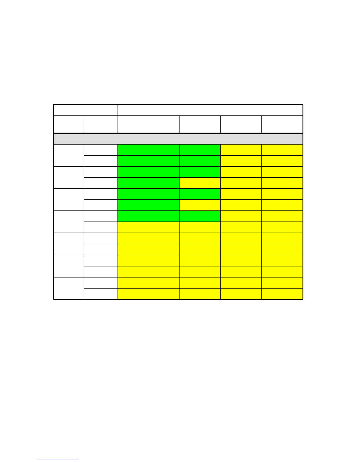
Chapter 3. IBM NeXtScale n1200 Enclosure 37
Table 3-8 shows the quantity supported of compute nodes with six 900 W power
supplies installed in the chassis with those power supplies connected to a
100-127 V (low-line) AC input.
Table 3-8 Number of compute nodes supported (low-line AC Input, with 6 x 900 W PSUs)
Compute nodes Power policy - 6 x 900W power supplies
CPU
TDP
Number of
CPUs
Non-redundant
or N+1 with OVS
a
a. OVS (oversubscription) of the power system allows for more efficient use of the available system
power.
N+1 N+N
N+N
with OVS
a
Low line AC input (100-127 V)
50 W 1
12 12 9 11
2
12 12 6 10
60 W 1
12 12 7 9
2
12 9 5 7
70 W 1
12 12 7 9
2
12 9 5 7
80 W 1
12 12 6 8
2
10 9 5 7
95 W 1
12 11 6 7
2
9 7 4 6
115 W 1
11 9 5 6
2
7 6 3 5
130 W 1
9 8 4 5
2
6 5 3 4
Page 56

38 IBM NeXtScale System Planning and Implementation Guide
3.4 Power supplies
The IBM NeXtScale n1200 Enclosure supports up to six high-efficiency
autoranging power supplies. The standard model includes all six power supplies.
A single power supply is shown in Figure 3-5.
Figure 3-5 900 W power supply
Table 3-9 lists the ordering information for the supported power supplies.
Table 3-9 Power supplies
The power supply options have the following features:
Supports N+N or N+1 Power Redundancy, or Non-redundant power
configurations to support higher density
Power management controller and configured through the Fan and Power
Controller
Integrated 2500 RPM fan
80 PLUS Platinum certified
Built-in overload and surge protection
Part
number
Feature
code
Description Min / Max
supported
Chassis
model
where used
00Y8569 A41T CFF 900 W Power Supply 6 / 6 A2x
00Y8652 A4MM CFF 1300W Power Supply 2 / 6 A3x, A4x
Page 57

Chapter 3. IBM NeXtScale n1200 Enclosure 39
900W power supply specifications:
Supports dual-range voltage: 100 - 240 V
100 - 127 (nominal) V AC; 50 or 60 Hz; 6.8 A (maximum)
200 - 240 (nominal) V AC; 50 or 60 Hz; 5.0 A (maximum)
1300W power supply specifications:
Supports high-range voltage only: 200 - 240 V
200 - 240 (nominal) V AC; 50 or 60 Hz; 6.9 A (maximum)
The location and numbering of the power supplies are shown in Figure 3-6.
Figure 3-6 IBM NeXtScale n1200 Enclosure rear view with power supply numbering
The power supplies that are used in IBM NeXtScale System are hot-swap,
high-efficiency 80 PLUS Platinum power supplies that are operating at 94%
efficiency. The efficiency varies by load, as shown in Table 3-10. The 80 PLUS
report is available at this website:
http://www.plugloadsolutions.com/psu_reports/IBM_7001700-XXXX_900W_SO-5
71_Report.pdf
1300W power supply: The 1300W power supply does not support low-range
voltages (100-127V).
Fan and Power
Controller
Static IP
User Name
Password
192.168.0.100
USERID
PASSW0RD
Zero
Default Information:
Event Log-AlternateAccess
via USB Key
USB key
Fan Baysand Power Supply
6 5 8
7
10
9
2
4
46
3
3
5
1
21
http://ibm.co/19pHxV8
5
3
1
6
4
2
Page 58

40 IBM NeXtScale System Planning and Implementation Guide
Table 3-10 Power efficiencies at different load levels
The 80 PLUS performance specification is for power supplies that are used
within servers and computers. To meet the 80 PLUS standard, the power supply
must have an efficiency of 80% or greater, at 20%, 50%, and 100% of rated load
with PF of 0.9 or greater. The standard has several grades, such as, Bronze,
Silver, Gold, and Platinum. For more information about the 80 PLUS standard,
see this website:
http://www.80PLUS.org
The power supplies receive electrical power from a 100 V - 127 V AC or 200 v 240 V AC power source and convert the AC input into DC outputs. The power
supplies can autorange within the input voltage range.
There is one common power domain for the chassis that distributes DC power to
each of the nodes and modules through the system midplane.
DC redundancy is achieved when there is one more power supply available than
is needed to provide full power to all chassis components. AC redundancy is
achieved by distributing the AC power cord connections between independent
AC circuits. For more information, see 5.1, “Power planning” on page 116.
Each power supply includes presence circuitry, which is powered by the
midplane. This allows the FPC to recognize when power supplies are installed in
the enclosure but are not powered by the AC supply.
The power supplies support oversubscription. By using oversubscription, users
can make the most of the extra power from the redundant power supplies when
the power supplies are in healthy condition. This means you can use the power
capacity of all installed power supplies while still preserving power supply
redundancy if there is a power supply failure. For more information, see “Power
supply oversubscription” on page 54.
20% load 50% load 100% load
80 PLUS Platinum standard 90.00% 94.00% 91.00%
NeXtScale n1200 900 W power supply 92.96% 94.15% 92.53%
NeXtScale n1200 1300 W power supply 93.97% 94.54% 92.65%
Use with 110-127 V AC: When low input voltage (100 V - 127 V AC) is used,
the power supply is limited to 600 W.
Page 59

Chapter 3. IBM NeXtScale n1200 Enclosure 41
As shown in Figure 3-5 on page 38, the following LEDs are on each power
supply:
AC power LED
When this LED is lit (green), it indicates that AC power is supplied to the
power supply.
DC power LED
When this LED is lit (green), it indicates that DC power is supplied from the
power supply to the chassis midplane.
Fault LED
When this LED is lit (yellow), it indicates that there is a fault with the power
supply.
Removing a power supply: To maintain proper system cooling, do not
operate the IBM NeXtScale n1200 Enclosure without a power supply (or
power supply filler) in every power supply bay. Install a power supply within 1
minute of the removal of a power supply.
Page 60

42 IBM NeXtScale System Planning and Implementation Guide
3.5 Fan modules
The IBM NeXtScale n1200 Enclosure supports 10, 80 mm fan modules. All fans
modules are at the rear of the chassis and are numbered as shown in Figure 3-7.
Figure 3-7 IBM NeXtScale n1200 Enclosure rear view with fan bay numbering
The fan modules provide cooling to the compute nodes. The fan modules have a
dual-rotor design for high efficiency and high reliability. Air flow is front-to-back.
Ordering information for the fan modules is shown in Table 3-11.
Table 3-11 Fan Modules
Part
number
Feature
code
Description Maximum
supported
Chassis
model
where used
00Y8570 A41F n1200 Fan Module 10 A2x
Fan and Power
Controller
Static IP
User Name
Password
192.168.0.100
USERID
PASSW0RD
Zero
Default Information:
Event Log-AlternateAccess
via USB Key
USB key
Fan Baysand Power Supply
6 5 8
7
10
9
2
4
46
3
3
5
1
21
http://ibm.co/19pHxV8
7
5
2134
6
8910
Page 61

Chapter 3. IBM NeXtScale n1200 Enclosure 43
The 80 mm fan module is shown in Figure 3-8.
Figure 3-8 80 mm fan module
Fan module controls and indicators
Each fan module has a Fault LED. When this LED is lit (yellow), it indicates that
the fan module failed.
The fan modules are not dedicated to cool a specific node. If there is a fan
module failure, the remaining functional fans speed up (if required) under the
control of the FPC to provide sufficient cooling to the chassis elements.
There are two logical cooling zones in the enclosure, as shown in Figure 3-9 on
page 44. Five fan modules on each side correspond to the six compute nodes on
that same side of the chassis.
Page 62

44 IBM NeXtScale System Planning and Implementation Guide
Figure 3-9 Cooling zones on the chassis
For each of the cooling zones (zone 1 or zone 2), the FPC sets the respective
fans for the corresponding nodes to the appropriate cooling values that are
required to cool those nodes. The FPC varies the speeds of the fans in zone 1
and zone 2 by at most a 20% difference to avoid unbalanced air flow distribution.
Fan removal: To maintain proper system cooling, do not operate the IBM
NeXtScale n1200 Enclosure without a fan module (or fan module filler) in
every fan module bay. Install a fan module within 1 minute of the removal of a
fan module.
Cooling zone 2
Cooling zone 1
Page 63
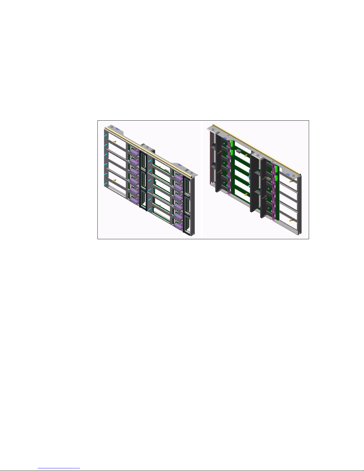
Chapter 3. IBM NeXtScale n1200 Enclosure 45
3.6 Midplane
The enclosure midplane is the bridge to connect the compute nodes with the
power supplies, fan modules, and the FPC. Figure 3-10 shows the front and rear
of the midplane.
Figure 3-10 Front and rear view of the n1200 Enclosure Midplane Assembly
The midplane is used to provide power to all elements in the chassis. It also
provides signals to control fan speed, power consumption, and node throttling.
The midplane was designed with no active components to improve reliability and
minimize serviceability. Unlike BladeCenter, for example, the midplane is
removed by removing a cover on the top of the chassis.
Front view Rear view
Page 64

46 IBM NeXtScale System Planning and Implementation Guide
Figure 3-11 shows the connectivity of the chassis components through the
midplane.
Figure 3-11 Midplane connectivity
Midplane
Fan and Power
Controller
Servers
Power
Supplies
Fan
Modules
Power
Supplies
Fan
Modules
I2C
Mux
12
FPC
12
ARM
SOC
RJ45
I2C
Mux
USB
Page 65

Chapter 3. IBM NeXtScale n1200 Enclosure 47
3.7 Fan and Power Controller
FPC controls the power budget, gives the power permission to each node, and
controls the speed of the fans. The FPC is installed inside the chassis and is
accessible from the rear of the chassis, as shown in Figure 3-12. The FPC is a
hot-swap component, as indicated by the orange handle.
Figure 3-12 Rear view of the chassis that shows the location of the FPC
Page 66

48 IBM NeXtScale System Planning and Implementation Guide
3.7.1 Ports and connectors
The FPC provides integrated systems management functions. The user
interfaces (browser and CLI) are accessible remotely via the 10/100 Mbps
Ethernet port.
Figure 3-13 shows the FPC and its LEDs.
Figure 3-13 FPC
The FPC has the following LEDs and connector that you can use to obtain status
information and restart the FPC:
Power LED
When this LED is lit (green), it indicates that the FPC has power.
Heartbeat LED
When this LED is lit (green), it indicates that the FPC is actively controlling the
chassis.
Locator LED
When this LED is lit (blue), it indicates the chassis location in a rack.
Check log LED
When this LED is lit (yellow), it indicates that a system error occurred.
Ethernet port activity LED
When this LED is flashing (green), it indicates that there is activity through the
remote management and console (Ethernet) port over the management
network.
Power LED
Heartbeat LED
Locator LED
USB key
Ethernet port link LED
Ethernet port activity LED
Check log LED
Page 67

Chapter 3. IBM NeXtScale n1200 Enclosure 49
Ethernet port link LED
When this LED is lit (green), it indicates that there is an active connection
through the remote management and console (Ethernet) port to the
management network.
Remote management and console (Ethernet) connector
The remote management and console RJ45 connector is the management
network connector for all chassis components. This 10/100 Mbps Ethernet
connector is connected to the management network through a top-of-rack
switch.
3.7.2 Internal USB memory key
The FPC also includes a USB key that is housed inside the unit, as shown in
Figure 3-14.
Figure 3-14 Internal view of the FPC
Note: The FPC is not a point of failure for the chassis by design. If the FPC
fails, the compute nodes, power supplies, and fans remain functional to keep
the systems running. The power capping policies that are set to the chassis
and compute nodes remain in place. The fan speeds up to maximum speed to
provide maximum cooling protection for the compute nodes until the FPC is
replaced.
Page 68

50 IBM NeXtScale System Planning and Implementation Guide
The USB key saves the following information:
Event log
Enclosure configuration data:
– PSU redundancy setting
– Oversubscription mode setting
– Chassis/node-level power capping value and settings
– Power restore policy
– Acoustic mode setting
Midplane vital product data (VPD)
If the FPC fails and must be replaced, users can restore the configuration data to
the new FPC by transferring the USB from the old unit to the new unit.
3.7.3 Overview of functions
The FPC performs the following functions:
Controls the power and power management features of the chassis, compute
nodes, and power supplies. The FPC prevents a compute node from
powering on if there is insufficient power.
Controls the cooling of the chassis. The FPC ramps up fan speeds if
conditions require more cooling (or slow down the fans to conserve energy if
higher fan speeds are not required).
Provides the following user interfaces:
– Web interface
– IPMI command line (for external management tools, such as, xCAT)
Allows you to select one of the following power supply redundancy policies:
– N+1, where one power supply is redundant and allows for a single power
supply to fail without any loss of function.
– N+N, where half the power supplies are redundant backups of the other
half. This is useful if you have two power utility sources and want the
chassis to survive the failure of one of the utility sources.
– Non-redundant, which maximizes the power that is available to the
compute nodes at the expense of power supply redundancy.
– Oversubscription, which can be enabled with N+1 and N+N policies.
Support the updating of FPC firmware.
Monitors and reports fan, power, and chassis status and other failures with
event log and corresponding LEDs.
Page 69

Chapter 3. IBM NeXtScale n1200 Enclosure 51
3.7.4 Web GUI interface
Through the FPC web interface, the user or system administrator can perform
the following tasks. For more information about the FPC web interface, see 7.2.1,
“FPC web browser interface” on page 180:
View summary of elements status:
– Front and rear view of the chassis
– Compute nodes location and status
– FPC, power supplies, fan modules location, and status
View current power usage:
– Voltage overview of the chassis
– Total chassis power consumption (AC-in)
– Total PSU power consumption (DC-out)
– Total fans power consumption
– Per-node power consumption
– Power supply fan speeds
View and set power supply redundancy and oversubscription:
– Select N, N+1, or N+N mode
– Enable or disable oversubscription mode
View and set power capping:
– Node level: Set value within a defined range for each node separately, or
choose between one of the three predefined modes.
– Chassis level: Set value within a defined range for the enclosure, or
choose between one of the three predefined modes.
View and set power restore policy: Enable or disable (for each node or
chassis)
View current fan speeds
View and set Acoustic mode (three modes)
View Chassis, Midplane, and FPC vital product data (VPD) details
View, save, and clear the system event log
View and set network configuration:
– SMTP configuration
– SNMP traps and email alert configuration
– Host name, DNS, Domain, IP, and IP version configuration
– SNMP traps email alert configuration
– Web server (http or https) ports configuration
Perform a Virtual Reset or Virtual Reseat of each compute node
Page 70

52 IBM NeXtScale System Planning and Implementation Guide
Set Locator (Identify) LED to on, off, or blink
Turn off Check Log LED
Back up and restore FPC configuration to USB key; reset to default
Perform firmware update
Set date and time
Perform user account management
3.8 Power management
The FPC controls the power on the IBM NeXtScale n1200 Enclosure. If there is
sufficient power available, the FPC allows a compute node to be powered on.
The power permission includes the following two-step process:
1. Pre-boot (BMC stage) inventory power (standby power) is pre-determined
based on the node type.
2. Post-boot (UEFI stage) inventory power is a more accurate estimation of the
node’s maximum power usage that is based on power maximizer test. The
following values are generated:
– Maximum power usage value under stressed condition.
– Maximum power usage value under stressed condition when P-state is
capped at the lowest level.
The FPC uses these values to compare the total node power and total available
power to determine power-on and boot permissions.
3.8.1 Power Restore policy
By using the Power Restore policy, you can specify whether you want the
compute nodes to restart when a chassis AC power is removed and restored.
This is similar to the Automatic Server Restart (ASR) feature of many System x
servers. For more information about the Power Restore Policy, see “Power
Restore Policy tab” on page 189.
When Power Restore policy is enabled, if the compute node was powered on
before the AC power cycle, the FPC turns the compute node back on
automatically when power is restored.
Page 71

Chapter 3. IBM NeXtScale n1200 Enclosure 53
However, a compute node is restarted only if the FPC determines there is
sufficient power available to power on the server, which is based on the following
factors:
Number of working power supplies
Power policy that is enabled
The oversubscription policy
If there is insufficient power, some compute nodes are not powered on. The
nodes are powered on based on their power usage, lowest first. The objective is
to maximize the number of nodes that can be powered on in a chassis. The
power-on sequence nominally takes about 2 minutes with most of that time spent
by the nodes running a power maximizer. After that is complete, the FPC can
quickly release the nodes to continue to boot.
3.8.2 Power capping
User can choose chassis-level capping or saving or node-level capping or saving
through the power cap configuration options. Power capping allows users to set
a wattage limit on power usage. When it is applied to an individual node, the
node power consumption is capped at an assigned level. When it is applied to a
chassis, the whole chassis power usage is capped. When power saving is
enabled, an individual node or all nodes (chassis level) run in modes of different
throttling level, depending on the modes that are chosen.
3.8.3 Power supply redundancy modes
The FPC offers the following modes from which to choose:
No-redundancy mode
The loss of any power supply can affect the system’s operation or
performance. If the chassis is evaluated to be vulnerable, because of the
failure of one or multiple power supplies, throttle signals are sent to all nodes
in the chassis to be throttled down to the lowest power level possible (CPU or
Memory lowest P-state). In case the power usage remains too high, the
chassis is shut down.
This is the default mode. This mode does not support the oversubscription
mode (see “Power supply oversubscription” on page 54).
N+1 Mode
One installed power supply is used as redundant. The failure of one power
supply is allowed without affecting the system’s operation or performance
(performance can be affected if oversubscription mode is enabled).
This mode can be enabled with oversubscription mode.
Page 72

54 IBM NeXtScale System Planning and Implementation Guide
N+N Mode
Half of the power supplies that are installed are used as redundant. The
failure of up to half the number of the power supplies is allowed without
affecting the system’s operation or performance (performance can be
affected if oversubscription mode is enabled). This mode is useful if you have
two power sources from two separate PDU for example.
This mode can be enabled with oversubscription mode.
3.8.4 Power supply oversubscription
By using oversubscription, users can make the most of the extra power from the
redundant power supplies when the power supplies are in healthy condition.
For example, when oversubscription is enabled with N+1 redundancy mode, the
total power that is available is equivalent to No Redundancy mode with six power
supplies in the chassis. This means we can count on the power of six power
supplies instead of five for normal operation.
When oversubscription mode is enabled with redundant power (N+1 or N+N
redundancy), the total available power is 120% of the label ratings of the power
supplies. So, for a 900 W power supply, it can be oversubscribed to 900 W x
120% = 1080 W.
For example, this means that with an N+1 power policy and six power supplies,
instead of 5 x 900 W (4500 W) of power, you have 5 x 900 W x 120% (5400 W) of
power that is available to the compute nodes.
Table 3-12 shows the power budget that is available, depending on the
redundancy and oversubscription mode that is selected.
Table 3-12 Power budget for 6 x 900 W power supplies
Redundancy Mode Oversubscription mode Power budget
a
a. The power budget that is presented in this table is based on power supply
ratings. Actual power budget can vary.
Non-redundant Not available 5400 W (= 6 x 900 W)
N+1
Disabled 4500 W (= 5 x 900 W)
Enabled 5400 W (= 5 x 900 W x 120%)
N+N
Disabled 2700 W (= 3 x 900 W)
Enabled 3240 W (= 3 x 900 x 120%)
Page 73

Chapter 3. IBM NeXtScale n1200 Enclosure 55
When oversubscription mode is enabled with redundant power (N+1 or N+N
redundancy), the chassis’ total available power can be stretched beyond the
label rating (up to 120%). However, the power supplies are designed to sustain
this oversubscription for a limited time (approximately 1 second).
In healthy condition (all power supplies are in normal-operational mode), the
redundant power supplies provide the extra 20% power oversubscription load for
the rest of the normal-operational power supplies (none of the power supplies
are oversubscribed).
When redundant power supplies fail (that is, one power supply failure in N+1
mode, or up to N power supplies fail in N+N mode), the remaining
normal-operational power supplies provide the extra 20% power
oversubscription load. This extra power is provided only for a limited time to allow
the compute nodes to throttle to the lowest P-state to reduce their power usage
back to a supported range. By design, the compute nodes perform this action
quickly enough and operation continues.
The Table 3-13 shows the consequences of redundancy failure in the chassis
with and without oversubscription mode.
Table 3-13 Consequences of power supply failure, depending on the oversubscription
Non-redundant mode: It is not possible to enable the oversubscription mode
without any power redundancy.
Redundancy
mode
Oversubscription
mode
Consequences of redundancy failure
a
a. Considering one power supply failure in non-redundant and N+1 mode, and
three power supplies failures in N+N mode.
Compute nodes
might be throttled
b
b. Compute nodes are throttled only if they require more power than what is
available on the remaining power supplies.
Chassis might
power off
Non-redundant Not available Yes Yes
c
c. The chassis is powered off only if after throttling the compute nodes, the
enclosure power requirement still exceeds the power that is available on the
remaining power supplies.
N+1
Disabled
No No
Enabled Yes
No
N+N
Disabled
No No
Enabled Yes
No
Page 74

56 IBM NeXtScale System Planning and Implementation Guide
3.8.5 Acoustic mode
By using acoustic mode, the user has some control over the fan speeds and
airflow (and noise) that is produced by the system fans. This mode can be used
for noise or airflow concerns in the user environment.
When the option is set to Off, the fan speeds change as required for optimal
cooling.
When the option is set to On, the chassis offers the following set points where the
fan speeds are capped:
1: highest acoustics attenuation (lowest cooling)
2: intermediate acoustics attenuation
3: low acoustics attenuation (higher cooling).
As a result, these settings increase the possibility that the node might have to be
throttled to maintain cooling within the fan speed limitation.
The acoustic mode setting should be balanced with the customer’s workload for
best performance.
Page 75

Chapter 3. IBM NeXtScale n1200 Enclosure 57
3.9 Specifications
This section describes the specifications of the IBM NeXtScale n1200 Enclosure.
3.9.1 Physical specifications
The enclosure features the following physical specifications:
Dimensions:
– Height: 263.3 mm (10.37 in.)
– Depth: 914.5 mm (36 in.)
– Width: 447 mm (17.6 in.)
Weight:
– Fully configured (stand-alone): Approximately 112 kg (247 lbs.)
– Empty chassis: approximately 28 kg (62 lbs.)
Approximate heat output:
– Ship configuration: 341.18 Btu/hr (100 watts)
– Full configuration: 20,470.84 Btu/hr (6,000 watts)
Declared sound power level: 7.5 bels
Chassis airflow:
Full chassis configuration with all compute nodes, FPC, power supplies, and
fan modules installed:
– Minimum: 158 CFM (idle)
– Maximum: 614 CFM
3.9.2 Supported environment
The IBM NeXtScale n1200 Enclosure complies with the following ASHRAE class
A3 specifications.
Power on
1
:
– Temperature: 5°C - 40°C (41°F - 104°F)
2
– Humidity, non-condensing: -12°C dew point (10.4°F) and 8% - 85%
relative humidity 5, 6
– Maximum dew point: 24°C (75°F)
– Maximum altitude: 3048 m (10,000 ft.)
– Maximum rate of temperature change: 5°C/hr. (41°F/hr.)
3
1
Chassis is powered on.
2
A3 - Derate maximum allowable temperature 1°C/175 m above 950 m.
Page 76

58 IBM NeXtScale System Planning and Implementation Guide
Power off4:
– Temperature: 5°C to 45°C (41°F - 113°F)
– Relative humidity: 8% - 85%
– Maximum dew point: 27°C (80.6°F)
Storage (non-operating):
– Temperature: 1°C to 60°C (33.8°F - 140°F)
– Altitude: 3050 m (10,006 ft.)
– Relative humidity: 5% - 80%
– Maximum dew point: 29°C (84.2°F)
Shipment (non-operating)
5
:
– Temperature: -40°C to 60°C (-40°F - 140°F)
– Altitude: 10700 m (35,105 ft.)
– Relative humidity: 5% - 100%
– Maximum dew point: 29°C (84.2°F)
6
3
5°C per hour for data centers that use tape drives and 20°C per hour for data centers that use disk
drives.
4
Chassis is removed from original shipping container and is installed but not in use; for example,
during repair, maintenance, or upgrade.
5
The equipment acclimation period is 1 hour per 20 °C of temperature change from the shipping
environment to the operating environment.
6
Condensation is acceptable, but not rain.
Page 77

© Copyright IBM Corp. 2013, 2014. All rights reserved. 59
Chapter 4. IBM NeXtScale nx360 M4
compute node
The IBM NeXtScale nx360 M4 compute node, machine type 5455, is a half-wide,
dual-socket server that is designed for data centers that require high
performance but are constrained by floor space. It supports Intel Xeon
E5-2600 v2 series processors up to 12 cores, which provide more performance
per server than previous generation systems.
With more computing power per watt and the latest Intel Xeon processors, you
can reduce costs while maintaining speed and availability. A total of 12 nx360 M4
servers can be installed into the 6U NeXtScale n1200 enclosure.
This chapter describes the nx360 M4 compute node and includes the following
topics:
4.1, “Overview” on page 60
4.2, “System architecture” on page 63
4.3, “Specificiations” on page 67
4.4, “Standard models” on page 69
4.5, “Processor options” on page 70
4.6, “Memory options” on page 71
4.7, “Internal disk storage options” on page 77
4.8, “IBM NeXtScale Storage Native Expansion Tray” on page 86
4.9, “IBM NeXtScale PCIe Native Expansion Tray” on page 90
4
Page 78
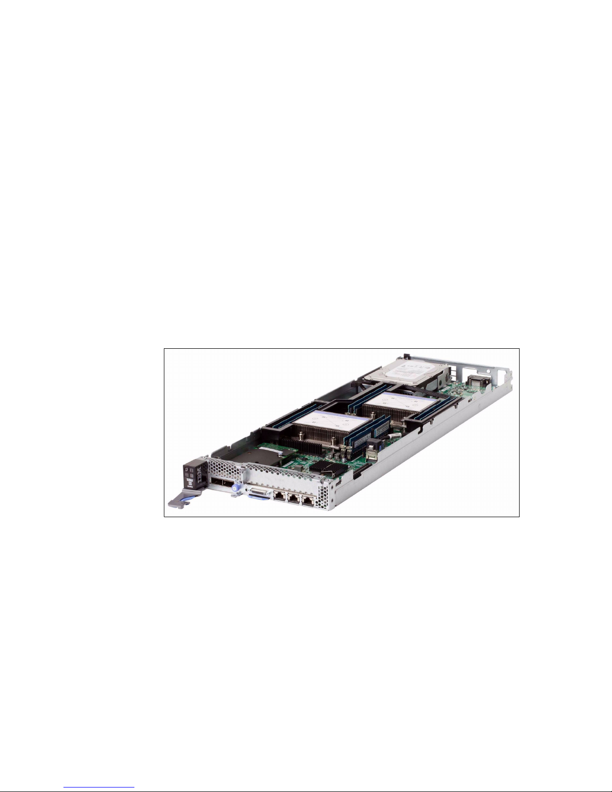
60 IBM NeXtScale System Planning and Implementation Guide
4.10, “GPU and coprocessor adapters” on page 92
4.11, “Embedded 1 Gb Ethernet controller” on page 96
4.12, “PCI Express I/O adapters” on page 97
4.13, “Integrated virtualization” on page 102
4.14, “Local server management” on page 103
4.15, “Remote server management” on page 105
4.16, “External disk storage expansion” on page 107
4.17, “Physical specifications” on page 110
4.18, “Operating systems support” on page 112
4.1 Overview
The IBM NeXtScale nx360 M4 compute node contains only the essential
components in the base architecture to provide a cost-optimized platform. The
nx360 M4 compute node provides a dense, flexible solution with a low total cost
of ownership.
Figure 4-1 IBM NeXtScale nx360 M4 compute node
The nx360 M4 compute nodes fit into the IBM NeXtScale n1200 Enclosure that
provides common power and cooling resources. As shown in Figure 4-1, the
nx360 M4 compute node can support the following components:
One or two Intel Xeon E5-2600 v2 series processors.
Up to eight DIMMs of registered DDR3 ECC memory and operating up to
1866 MHz, which provides a total memory capacity of up to 128 GB.
One on-board 1 Gb Ethernet port and one on-board 1 Gb
Ethernet/management port.
Page 79

Chapter 4. IBM NeXtScale nx360 M4 compute node 61
An Integrated Management Module II (IMM2) port for server remote
management and an integrated industry-standard Unified Extensible
Firmware Interface (UEFI), which enables improved setup, configuration, and
updates.
One 3.5-inch drive bay, or alternatively two 2.5-inch drive bays or four
1.8-inch drive bays.
Support for additional local storage with the use of the Storage Native
Expansion Tray. When using 4 TB HDDs, you can create an ultra-dense
storage server with up to 32 TB of total disk capacity within 1U of comparable
rack density.
A slot for 10 Gb Ethernet or FDR InfiniBand mezzanine for network
connectivity without using a PCIe slot.
PCI Express 3.0 I/O expansion capabilities through a 16x riser cage.
Additional support for two GPUs or coprocessors with the use of the PCIe
Native Expansion Tray.
4.1.1 Physical design
Figure 4-2 shows the controls and connections on the front of the server.
Figure 4-2 Front view of IBM NeXtScale nx360 M4
Power
button and
information
LEDs
PCIe 3.0 slot
full height, half length
Dual-port
mezzanine
adapter slot
KVM
connector
1 GbE
(dedicated)
1 GbE or IMM
management
port (shared)
IMM
management
port (dedicated)
Page 80

62 IBM NeXtScale System Planning and Implementation Guide
Figure 4-3 shows the locations of key components inside the server.
Figure 4-3 Inside view of the IBM NeXtScale nx360 M4
CPU 2 and
four DIMMs
CPU 1 and
four DIMMs
Mezz card
connector
PCIe 3.0
riser slot 1
PCIe 3.0
riser slot 2
(PCIe Tray only)
USB hypervisor
socket
Midplane
connector
KVM and
Ethernet
Drive bay(s)
SATA port
and cable
Page 81

Chapter 4. IBM NeXtScale nx360 M4 compute node 63
Figure 4-4 shows an exploded window of the platform, in which the major
components and options are highlighted.
Figure 4-4 Exploded view of the nx360 M4
4.2 System architecture
The IBM NeXtScale nx360 M4 compute node features the Intel E5-2600 v2
series processors. The Xeon E5-2600 v2 series processor has models with
either 6, 8, 10, or 12 cores per processor with up to 24 threads per socket.
The Intel Xeon E5-2600 v2 series processors (formerly known by the Intel code
name
Ivy Bridge-EP) are the successors of the first implementation of Intel’s
micro architecture that is based on tri-gate transistors, Intel Xeon E5-2600 series
(formerly
Sandy Bridge-EP). The Xeon E5-2600 v2 series uses a 22nm
manufacturing process in contrast to the 32nm used by its predecessor. By using
this new, smaller 22nm tri-gate transistor technology, you can design more
powerful processors with better power efficiency.
Cover
1.8-inch drives,
backplane & cage
2.5 drives,
backplane
& cage
3.5-inch drive
and carrier
DIMM
Air baffle
PCIe riser
Battery
holder
Air baffle
Slot
covers
Air
baffles
Page 82

64 IBM NeXtScale System Planning and Implementation Guide
Such new tri-gate transistor technology enabled a new architecture with which
you can share data on-chip through a high-speed ring that is interconnected
between all processor cores, the last level cache (LLC), and the system agent.
The system agent houses the memory controller and a PCI Express root
complex that provides 40 PCIe 3.0 lanes.
The integrated memory controller in each CPU still supports four memory
channels with three DDR3 DIMMs per channel but now runs at a speed that is up
to 1866 MHz. Two QPI links still also connect to a second CPU in a dual-socket
installation.
The Xeon E5-2600 v2 series is available with up to 12 cores and 30 MB of
last-level cache. It features an enhanced instruction set that is called Intel
Advanced Vector Extensions (AVX). It doubles the operand size for vector
instructions (such as floating-point) to 256 bits and boosts selected applications
by up to a factor of two.
The implementation architecture includes Intel Turbo Boost Technology 2.0 and
improved power management capabilities. Turbo Boost automatically turns off
unused processor cores and increases the clock speed of the cores in use if
thermal requirements are still met. Turbo Boost Technology 2.0 uses the
integrated design and implements a more granular overclocking in 100 MHz
steps instead of 133 MHz steps on older microprocessors.
As with iDataPlex servers, NeXtScale servers support S3 mode. S3 allows
systems to come back into full production from low-power state much quicker
than a traditional power-on. In fact, cold boot normally takes about 270 seconds;
with S3, cold boot occurs in only 45 seconds. When you know a system will not
be used because of time of day or state of job flow, you can send it into a very
low-power state to save power and bring it back online quickly when needed.
Table 4-1 summarizes the differences between both Intel’s micro architecture
implementations. Improvements are highlighted.
Table 4-1 Comparison between Xeon E5-2600 and Xeon E5-2600 v2
Xeon E5-2600
(Sandy Bridge-EP)
Xeon E5-2600 v2
(Ivy Bridge-EP)
QPI Speed (GT/s) 8.0, 7.2 and 6.4 GT/s
Addressability 46 bits physical, 48 bits virtual
Cores Up to 8
Up to 12
Threads per socket Up to 16 threads
Up to 24 threads
Last-level Cache (LLC) Up to 20 MB
Up to 30 MB
Page 83

Chapter 4. IBM NeXtScale nx360 M4 compute node 65
Figure 4-5 shows the IBM NeXtScale nx360 M4 building block.
Figure 4-5 IBM NeXtScale nx360 M4 system board block diagram
Intel Turbo Boost Technology Yes
Memory population 4 channels of up to 3 RDIMMs, 3 LRDIMMs, or 2 UDIMMs
Maximum memory speed Up to 1600 MHz Up to 1866 MHz
Memory RAS features ECC, Patrol Scrubbing, Sparring, Mirroring, Lockstep Mode, x4/x8
SDDC
PCIe lanes 40 PCIe 3.0 lanes
TDP values (W) 130, 115, 96, 80, 70, 60, 50 W
Idle power targets (W) 15 W or higher
12 W for low-voltage SKUs
10.5 W or higher
7.5 W for low-voltage SKUs
Xeon E5-2600
(Sandy Bridge-EP)
Xeon E5-2600 v2
(Ivy Bridge-EP)
DIMM
DIMM
DIMM
DIMM
DIMM
DIMM
DIMM
DIMM
QPI
links
x4 ESI link
PCIe riser slot
1x 3.5” or
2x 2.5” or
4x 1.8”
2x 6 Gbps AHCI &
2x 3 Gbps AHCI
USB
Internal
Intel
C602J
PCH
Dedicated RJ45 port
Front KVM port
IMM v2
Video &
serial
Mezzanine slot
GPU riser slot
PCIe 3.0 x24
PCIe 3.0 x8
PCIe 3.0 x16
Intel
Xeon
Processor 1
DDR3 DIMMs
4 memory channels
1 DIMM per channel
x1 USB
Intel
Xeon
Processor 2
USB
PCIe 3.0 x4
GbE
Two GbE
ports (RJ45)
Page 84

66 IBM NeXtScale System Planning and Implementation Guide
The nx360 M4 architecture contains the following components:
Two 2011-pin, Socket R (LGA-2011) processor sockets
Intel C602J Platform Controller Hub (PCH)
Four memory channels per socket
One DIMM per memory channel (DPC)
Eight DDR3 DIMM sockets (when only one processor is installed, only four
DIMM sockets can be used)
Support for UDIMMs and RDIMMs
A PCI Express 3.0 x8 slot for Mezzanine card connection that connects to
CPU 1
A PCI Express 3.0 x24 slot for PCIe riser cage that provides a
full-height/half-length (FHHL) slot that connects to CPU 1
A PCI Express 3.0 x16 slot that is connected to CPU 2 (for use with attached
trays)
Dual-port integrated 1 Gb controller
An Integrated Management Module v2 (IMMv2) for remote server
Note: Although the Socket R (LGA-2011) processor socket on the nx360 M4
physically fits Xeon E5-2600 series and Xeon E5-2600 v2 series processor,
only the latter are supported as processor options for this platform.
Page 85

Chapter 4. IBM NeXtScale nx360 M4 compute node 67
4.3 Specificiations
Table 4-2 lists the standard specifications of the NeXtScale nx360 M4 compute
node and NeXtScale n1200 enclosure.
Table 4-2 Specificaitons
Components Specification
Form factor Half-wide, 1U compute node
Supported
chassis
IBM NeXtScale n1200 enclosure, 6U high; up to 12 compute nodes per chassis
Processor Two Intel Xeon Processor E5-2600 V2 series processors; QuickPath Interconnect
(QPI) links speed up to 8.0 GT/s. Hyper-Threading Technology and Turbo Boost
Technology. Intel C602J (Patsburg-J) chipset. Processor options:
4-core processors up to 3.5 GHz and 15 MB L3 cache
6-core processors up to 3.5 GHz and 25 MB L3 cache
8-core processors up to 3.3 GHz and 25 MB L3 cache
10-core processors up to 3.0 GHz and 25 MB L3 cache
12-core processors up to 2.7 GHz and 30 MB L3 cache
Memory Up to 8 DIMM sockets (4 DIMMs per processor) supporting DDR3 DIMMs up to 1866
MHz memory speeds. RDIMMs, UDIMMs and LRDIMMs supported. Four memory
channels per processor (one DIMM per channel).
Memory
maximums
Up to 256 GB with 8x 32 GB LRDIMMs and two processors.
Memory
protection
ECC, memory mirroring, and memory sparing.
Disk drive bays Inside the nx360 M4: One 3.5-inch simple-swap SATA or two 2.5-inch simple swap
SAS/SATA HDDs or SSDs, or four 1.8-inch simple-swap SSDs. Not front accessible.
Adding the NeXtScale Storage Native Expansion Tray adds 7 more 3.5-inch
simple-swap drive bays (adds 1U height).
Maximum
internal storage
With the Storage Native Expansion Tray: 32 TB using 8x 4TB 3.5-inch drives.
Without the Storage Native Expansion Tray: 4.0 TB using 1x 4TB 3.5-inch drive.
RAID support On some models: ServeRAID C100 6Gb SATA controller supporting RAID-0, RAID-1
and RAID-10. Implemented in the Intel C600 chipset. Optional hardware RAID with
supported 6Gbps RAID controllers.
Optical drive
bays
No internal bays. Use an external USB drive such as the IBM and Lenovo part number
73P4515 or 73P4516.
Tape drive bays No internal bays. Use an external USB drive.
Page 86

68 IBM NeXtScale System Planning and Implementation Guide
Network
interfaces
Two Gigabit Ethernet ports using onboard Intel I350 Gb Ethernet controller.
Optionally, two InfiniBand ports or two 10 GbE ports via a mezzanine card (which does
not occupy the available PCIe slot).
PCI Expansion
slots
nx360 M4 without PCIe Native Expansion Tray:
One PCIe 3.0 x8 mezzanine card slot
One PCIe 3.0 x16 full-height half-length slot
nx360 M4 with PCIe Native Expansion Tray (addes 1U height):
One PCIe 3.0 x8 mezzanine card slot
One PCIe 3.0 x8 full-height half-length slot
Two PCIe 3.0 x16 full-height full-length double-width slots for GPUs
Ports (server) Front of the server: KVM connector; with the addition of a console breakout cable (1
cable standard with the chassis) supplies one RS232 serial port, one VGA port and
two USB ports for local console connectivity. Three 1 Gbps Ethernet ports with RJ45
connectors: one dedicated for systems management (wired to the IMM), one
dedicated for use by the operating system and one shared by the IMM and the
operating system. One slot for an optional mezzanine card ports (QSFP, SFP+ or
RJ45 depending on the card installed). One internal USB port for VMware ESXi
hypervisor key.
Ports (chassis) Rear of the enclosure, provided by the Fan and Power Controller Module for chassis
management: Gb Ethernet connection (RJ45) for browser-based remote
management, mini-USB serial port for local management.
Cooling Supplied by the NeXtScale n1200 enclosure. 10 hot-swap dual-rotor 80 mm system
fans with tool-less design.
Power supply Supplied by the NeXtScale n1200 enclosure. Up to six hot-swap power supplies either
900W or 1300W depending on the chassis model. Support power policies N+N or N+1
power redundancy. 80 PLUS Platinum certified.
Video Matrox G200eR2 video core with 16 MB DDR3 video memory integrated into the
IMM2. Maximum resolution is 1600x1200 with 16M colors (32 bpp) at 75 Hz, or
1680x1050 with 16M colors at 60 Hz. Optional GPUs in PCIe Native Exp. Tray.
Systems
management
UEFI, IBM Integrated Management Module II (IMM2) with Renesas SH7757
controller, Predictive Failure Analysis, Light Path Diagnostics, Automatic Server
Restart, IBM Systems Director and IBM Systems Director Active Energy Manager,
IBM ServerGuide. Browser-based chassis management via Ethernet port on the Fan
and Power Controller Module on the rear of the enclosure. IMM2 upgrades available
to IMM2 Standard and IMM2 Advanced for web GUI and remote presence features.
Security features Power-on password, administrator's password, Trusted Platform Module 1.2.
Operating
systems
supported
Red Hat Enterprise Linux, SUSE Linux Enterprise Server, Microsoft Windows Server
2008 R2 and 2008, VMware vSphere Hypervisor.
Components Specification
Page 87

Chapter 4. IBM NeXtScale nx360 M4 compute node 69
4.4 Standard models
Table 4-3 lists the standard models of nx360 M4.
Table 4-3 Standard models of the nx360 M4
Limited warranty 3-year customer-replaceable unit and onsite limited warranty with 9x5/NBD.
Service and
support
Optional service upgrades are available through IBM ServicePacs®: 4-hour or 2-hour
response time, 8-hour fix time, 1-year or 2-year warranty extension, remote technical
support for IBM hardware and some IBM and OEM software.
Dimensions NeXtScale nx360 M4 server: Width: 216 mm (8.5 in), height: 41 mm (1.6 in), depth:
659 mm (25.9 in)
NeXtScale n1200 enclosure: Width: 447 mm (17.6 in), height: 263 mm (10.4 in),
depth: 915 mm (36 in.)
Weight NeXtScale nx360 M4 maximum weight: 6.05 kg (13.31 lb)
NeXtScale n1200 enclosure: Fully configured (stand-alone): 112 kg (247 lb), empty
chassis 28 kg (62 lb)
Components Specification
Model Intel Xeon processor
a
a. Processor detail: Processor quantity and model, cores, core speed, L3 cache, memory speed, and power consumption.
Memory
and
speed
Disk
adapter
Disk
bays
Disks Network
5455-22x 2x Intel Xeon E5-2620 v2 6C
2.1GHz 15MB 1600MHz 80W
2x 4 GB
1600 MHz
6 Gbps SATA
(No RAID)
1x 3.5”
SS bay
b
b. SS = simple swap
Open 2x GbE
5455-42x 2x Intel XeonE5-2660 v2 10C
2.2GHz 25MB 1866MHz 95W
2x 8 GB
1866 MHz
6 Gbps SATA
(No RAID)
1x 3.5”
SS bay
Open 2x GbE
5455-62x 2x Intel XeonE5-2670 v2 10C
2.5GHz 25MB 1866MHz 115W
2x 8 GB
1866 MHz
ServeRAID
C100
2x 2.5"
SS bays
Open 2x GbE
Page 88

70 IBM NeXtScale System Planning and Implementation Guide
4.5 Processor options
The nx360 M4 supports Xeon E5-2600 v2 processor series. The exact processor
options that can be selected for nx360 M4 compute node are listed in Table 4-4.
Table 4-4 Processor options
Part
number
Feature
code
a
a. The first feature code corresponds to the first processor; the second feature code corresponds to
the second processor.
Intel Xeon processors
b
Where
used
00FL128 A55N / A55W Intel Xeon E5-2603 v2 4C 1.8GHz 10MB 1333MHz 80W -
00FL129 A55P / A55X Intel Xeon E5-2609 v2 4C 2.5GHz 10MB 1333MHz 80W -
00Y8687 A4MF / A4MK Intel Xeon E5-2618L v2 6C 2.0GHz 15MB 1333MHz 50W -
46W2712 A425 / A42F Intel Xeon E5-2620 v2 6C 2.1GHz 15MB 1600MHz 80W 22x
00FL130 A55Q / A55Y Intel Xeon E5-2628L v2 8C 2.2GHz 20MB 1600MHz 70W -
00FL234 A55T / A561 Intel Xeon E5-2630 v2 6C 2.6GHz 15M 1600MHz 80W -
00FL131 A55R / A55Z Intel Xeon E5-2630L v2 6C 2.4GHz 15MB 1600MHz 60W -
00Y8632 A4MD / A4MH Intel Xeon E5-2637 v2 4C 3.5GHz 15MB 1866MHz 130W -
46W2719 A42B / A42M Intel Xeon E5-2640 v2 8C 2.0GHz 20MB 1600MHz 95W -
00FL126 A55L / A55U Intel Xeon E5-2643 v2 6C 3.5GHz 25MB 1866MHz 130W -
00Y8686 A4ME / A4MJ Intel Xeon E5-2648L v2 10C 2.0GHz 25MB 1866MHz 70W -
46W2713 A426 / A42G Intel Xeon E5-2650 v2 8C 2.6GHz 20MB 1866MHz 95W -
00FL132 A55S / A560 Intel Xeon E5-2650L v2 10C 1.7GHz 25M 1600MHz 70W -
00Y8688 A4MG / A4ML Intel Xeon E5-2658 v2 10C 2.4GHz 25MB 1866MHz 95W -
46W2714 A427 / A42H Intel Xeon E5-2660 v2 10C 2.2GHz 25MB 1866MHz 95W 42x
00FL127 A55M / A55V Intel Xeon E5-2667 v2 8C 3.3GHz 25MB 1866MHz 130W -
46W2715 A428 / A42J Intel Xeon E5-2670 v2 10C 2.5GHz 25MB 1866MHz 115W 62x
46W2716 A429 / A42K Intel Xeon E5-2680 v2 10C 2.8GHz 25MB 1866MHz 115W -
46W2717 A42A / A42L Intel Xeon E5-2690 v2 10C 3.0GHz 25MB 1866MHz 130W -
46W2720 A42C / A42N Intel Xeon E5-2695 v2 12C 2.4GHz 30MB 1866MHz 115W -
46W2721 A42D / A42P Intel Xeon E5-2697 v2 12C 2.7GHz 30MB 1866MHz 130W -
Page 89

Chapter 4. IBM NeXtScale nx360 M4 compute node 71
4.6 Memory options
IBM DDR3 memory is compatibility tested and tuned for optimal IBM System x
performance and throughput. IBM memory specifications are integrated into the
light path diagnostic tests for immediate system performance feedback and
optimum system uptime. From a service and support standpoint, IBM memory
automatically assumes the IBM system warranty, and IBM provides service and
support worldwide.
The NeXtScale nx360 M4 supports DDR3 memory. The server supports up to
four DIMMs when one processor is installed and up to eight DIMMs when two
processors are installed. Each processor has four memory channels. There is
one DIMM per memory channel (1 DPC).
Figure 4-6 shows the memory channel layout.
Figure 4-6 Memory channel layout of the IBM NeXtScale nx360 M4
b. Processor detail: Model, cores, core speed, L3 cache, memory speed, and TDP power.
Floating point performance: The number of sockets and the processor
option that are selected determine the theoretical floating point peak
performance, as shown in the following example:
#sockets x #cores per processor x freq x 8 flops per cycle = Gflops
A nx360 compute node with dual socket E5-2680 v2 series 10-core that
operates at 2.8 Ghz has the following peak performance:
2 x 10 x 2.8 x 8 = 448 Gflops
DIMM 3DIMM 2DIMM 1
Xeon E5-2600 v2
Processor 1
Channel A
Memory Controller
Channel B Channel C
QPI links
DIMM 4
Channel D
DIMM 7DIMM 6DIMM 5
Xeon E5-2600 v2
Processor 2
Channel A
Memory Controller
Channel B Channel C
DIMM 8
Channel D
Page 90

72 IBM NeXtScale System Planning and Implementation Guide
The following rules apply when you select the memory configuration:
Each installed processor must have at least one memory DIMM connected.
In the nx360 M4, the maximum memory speed of a configuration is the lower
of the following two values:
– The memory speed of the processor (see Table 4-4 on page 70)
– The memory speed of the DIMM (see Table 4-10 on page 76)
The server supports 1.5 V and 1.35 V DIMMs. Mixing 1.5 V and 1.35 V
DIMMs in the same server is supported. In such a case, all DIMMs operate at
1.5 V.
Mixing UDIMMs and RDIMMs is not supported.
Equally distribute DIMMs between sockets for best performance.
For optimal performance, populate the four memory channels when one
processor is installed and the eight DIMMs when two processors are
installed.
Table 4-5 lists the memory options that are available for the nx360 M4 server.
Table 4-5 Table 5. Memory options
Part
number
Feature
code
Description Maximum
supported
Models
where used
UDIMMs
00D5012 A3QB 4GB (1x4 GB, 2Rx8, 1.35 V) PC3L-12800
CL11 ECC DDR3 1600MHz LP UDIMM
8-
RDIMMs - 1866 MHz
00D5028 A3QF 4GB (1x4 GB, 2Rx8, 1.5 V) PC3-14900
CL13 ECC DDR3 1866MHz LP RDIMM
8-
00D5040 A3QJ 8GB (1x8 GB, 2Rx8, 1.5 V) PC3-14900
CL13 ECC DDR3 1866MHz LP RDIMM
8 42x, 62x
00D5048 A3QL 16GB (1x16 GB, 2Rx4, 1.5 V) PC3-14900
CL13 ECC DDR3 1866MHz LP RDIMM
8-
RDIMMs - 1600 MHz
00D5024 A3QE 4GB (1x4GB, 1Rx4, 1.35V) PC3L-12800
CL11 ECC DDR3 1600MHz LP RDIMM
8-
46W0735 A3ZD 4GB (1x4 GB, 2Rx8, 1.35 V) PC3-12800
CL13 ECC DDR3 1600MHz LP RDIMM
822x
Page 91

Chapter 4. IBM NeXtScale nx360 M4 compute node 73
The following memory protection technologies are supported:
ECC
Chipkill (for x4-based memory DIMMs; look for “x4” in the DIMM description;
for x8-based memory DIMMs, only ECC protection is supported)
Memory mirroring mode
Memory lock-step mode
When mirrored mode is used, DIMM 1 and DIMM 2 hold the same data for
redundancy purposes. If one DIMM fails, it is disabled and the backup DIMM in
the other channel takes over. Likewise, DIMM 3 and DIMM 4 hold the same data
and create a mirrored pair. Because memory mirroring is handled in hardware, it
is operating system-independent. The total usable memory size is half the total of
the installed memory.
Lock-step mode requires paired memory channels (DIMM 1 and DIMM 2,
DIMM 3 and DIMM 4) to be populated by the same memory regards the size and
the organization. Lock-step mode allows Single Device Data Correction (SDDC)
memory protection for x8-based memory DIMMs.
4.6.1 DIMM installation order
The IBM NeXtScale nx360 M4 boots with only one memory DIMM installed per
processor. However, the suggested memory configuration is to balance the
memory across all the memory channels on each processor to use the available
memory bandwidth. For best performance, it is recommended to populate all
DIMM slots.
00D5036 A3QH 8GB (1x8GB, 1Rx4, 1.35V) PC3L-12800
CL11 ECC DDR3 1600MHz LP RDIMM
8-
00D5044 A3QK 8GB (1x8 GB, 2Rx8, 1.35 V) PC3L-12800
CL11 ECC DDR3 1600MHz LP RDIMM
8-
46W0672 A3QM 16GB (1x16GB, 2Rx4, 1.35V) PC3L-12800
CL11 ECC DDR3 1600MHz LP RDIMM
8-
LRDIMMs
46W0761 A47K 32GB (1x32GB, 4Rx4, 1.5V) PC3-14900
CL13 ECC DDR3 1866MHz LP LRDIMM
8-
Part
number
Feature
code
Description Maximum
supported
Models
where used
Page 92
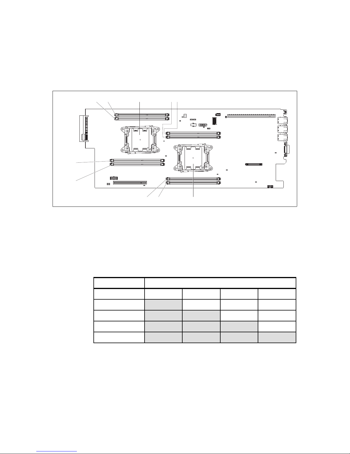
74 IBM NeXtScale System Planning and Implementation Guide
The locations of the DIMM sockets relative to the processors are shown in
Figure 4-7.
Figure 4-7 Memory DIMM slots
Memory DIMM installation: Independent channel mode
Independent channel mode provides a maximum memory of 64 GB of usable
memory with one installed processor, and 128 GB of usable memory with two
installed microprocessor (using 16 GB DIMMs).
Table 4-6 shows DIMM installation if you have one processor that is installed.
Table 4-6 Memory population with one processor installed
Table 4-7 on page 75 shows DIMM installation if you have two processors that
are installed. A minimum of two memory DIMMs (one for each processor) are
required when two processors are installed.
DIMM 1DIMM 2
DIMM 3
DIMM 4
DIMM 8DIMM 7
CPU 1
CPU 2
DIMM 5DIMM 6
Processor 1
Number of DIMMs DIMM 1 DIMM 2 DIMM 3 DIMM 4
1 x
2
x x
3
x x x
4
x x x x
Page 93

Chapter 4. IBM NeXtScale nx360 M4 compute node 75
Table 4-7 Memory population table with two processors installed
Memory DIMM installation: Mirrored-channel mode
In mirrored channel mode, the channels are paired and both channels in a pair
store the same data.
As shown in Table 4-8, for each microprocessor, DIMM 1 and DIMM 2 form a
redundant pair, and DIMM 3 and DIMM 4 form the other redundant pair. Because
of the redundancy, the effective memory capacity of the compute node is half the
installed memory capacity.
The pair of DIMMs that are installed in each channel must be identical in
capacity, type, and rank count.
Table 4-8 Memory population with processor stalled: Mirrored channel mode
Table 4-9 on page 76 shows DIMM installation for memory mirroring if two
processors are installed.
Processor 1 Processor 2
Number of
DIMMs
DIMM 1 DIMM 2 DIMM 3 DIMM 4 DIMM 5 DIMM 6 DIMM 7 DIMM 8
2
x x
3
x x x
4
x x x x
5
x x x x x
6
x x x x x x
7
x x x x x x x
8
x x x x x x x x
Processor 1
Number of DIMMs DIMM 1 DIMM 2 DIMM 3 DIMM 4
2 x x
4
x x x x
Page 94

76 IBM NeXtScale System Planning and Implementation Guide
Table 4-9 Memory population table with two processors installed: Mirrored channel mode
Table 4-10 (RDIMMs) and Table 4-11 on page 77 (UDIMMs and LRDIMMs) show
the maximum memory speeds that are achievable. The tables also show the
maximum memory capacity at any speed that is supported by the DIMM and the
maximum memory capacity at the rated DIMM speed.
Table 4-10 Maximum memory speeds (RDIMMs)
Processor 1 Processor 2
Number of
DIMMs
DIMM 1 DIMM 2 DIMM 3 DIMM 4 DIMM 5 DIMM 6 DIMM 7 DIMM 8
4 x x x x
6
x x x x x x
8
x x x x x x x x
Spec RDIMMs
Rank Single rank Dual rank
Part numbers 00D5024 (4GB)
00D5036 (8GB)
46W0735 (4 GB)
00D5044 (8 GB)
46W0672 (16GB)
00D5028 (4 GB)
00D5040 (8 GB)
00D5048 (16 GB)
Rated speed 1600 MHz 1600 MHz 1866 MHz
Rated voltage 1.35V 1.35 V 1.5 V
Operating voltage 1.35V or 1.5V 1.35V or 1.5V 1.5 V
Max quantity
a
a. The maximum quantity that is supported is shown for two installed processors. When one processor
is installed, the maximum quantity that is supported is half of that shown.
88 8
Largest DIMM 8 GB 16 GB 16 GB
Max memory capacity 64 GB 128 GB 128 GB
Max memory at rated speed 64 GB 128 GB 128 GB
Maximum operating speed (MHz)
1 DIMM per channel 1600 MHz 1600 MHz 1866 MHz
Page 95

Chapter 4. IBM NeXtScale nx360 M4 compute node 77
Table 4-11 Maximum memory speeds (UDIMMs and LRDIMMs)
4.7 Internal disk storage options
This section provides information about the internal storage options. The RAID
controller cards and the conventional and solid-state disks (SDDs) that are
supported also are listed.
The IBM NeXtScale nx360 M4 server supports one of the following drive options:
One 3.5-inch simple-swap SATA drive
Up to two 2.5-inch simple-swap SAS or SATA HDDs or SSDs
Up to four 1.8-inch simple-swap SSDs
Rules for mixing drive types:
Mixing HDDs: Simple-swap SATA HDDs and simple-swap SAS HDDs can be
intermixed in the system, but cannot be intermixed in the same RAID array.
Mixing HDDs and SSDs: Both simple-swap SATA HDDs and simple-swap
SAS HDDs can be intermixed with SSDs in the system. SAS or SATA HDDs
cannot be configured with SSDs within the same RAID array.
Spec UDIMMs LRDIMMs
Rank Dual rank Quad rank
Part numbers 00D5012 (4GB) 46W0761 (32GB)
Rated speed 1600 MHz 1866 MHz
Rated voltage 1.35V 1.5 V
Operating voltage 1.35V or 1.5V 1.5 V
Max quantity
a
a. The maximum quantity that is supported is shown for two installed processors. When one processor
is installed, the maximum quantity that is supported is half of that shown.
88
Largest DIMM 4 GB 32 GB
Max memory capacity 32 GB 256 GB
Max memory at rated speed 32 GB 256 GB
Maximum operating speed (MHz)
1 DIMM per channel 1600 MHz 1866 MHz
Page 96

78 IBM NeXtScale System Planning and Implementation Guide
In addition, the nx360 M4 supports seven additional 3.5-inch drive bays if the
IBM NeXtScale Storage Native Expansion Tray is attached. The Storage Native
Expansion Tray can be used with any of the above three internal drive
configurations to provide the following bay combinations:
Eight 3.5-inch simple-swap SATA drives
Seven 3.5-inch simple-swap SATA drives and two 2.5-inch simple-swap SATA
HDDs
Seven 3.5-inch simple-swap SATA drives and four 1.8-inch simple-swap
SSDs
We describe the Native Expansion Tray in detail in 4.8, “IBM NeXtScale Storage
Native Expansion Tray” on page 86.
Drive cages for the drives internal to the nx360 M4 are as listed in Table 4-12.
Drives used in the Storage Native Expansion Tray do not need a cage.
Table 4-12 Drive cages for the drive bay in the nx360 M4
Figure 4-8 shows the three disk drive bay options that are available for nx360 M4
compute node.
Figure 4-8 Drive bay options
Part number Feature
code
Description Models
where used
None
a
a. CTO only
A41N nx360 M4 1.8-inch SSD Cage Assembly -
None
a
A41K nx360 M4 2.5-inch HDD Cage Assembly 62x
None
a
A41J nx360 M4 3.5-inch HDD Cage Assembly 22x, 42x
00Y8615 A4GE 3.5" HDD RAID cage for nx360 M4
Storage Native Expansion Tray
-
O e35 c a dds d e
p p
One 3.5-inch HDD Up to two 2.5-inch HDDs or SSDs Up to four 1.8-inch SSD
Page 97

Chapter 4. IBM NeXtScale nx360 M4 compute node 79
The 3.5-inch drive slides in place. The 2.5-inch and 1.8-inch drive bays pivot up
so that you can insert the drives. You then pull the release pin and lower the drive
bays back into place.
There are two 3.5-inch drive cages - the last two rows of Table 4-12 on page 78.
If the Storage Native Expansion Tray is attached to the nx360 M4, then the use of
the RAID cage (feature A4GE, option 00Y8615) allows you to configure a RAID
array that spans all 8 drives - the 7 in the storage tray and the 1 drive internal to
the nx360 M4. Such a configuration would be connected either to a ServeRAID
M1115 adapter or N2115 SAS HBA.
If the 3.5-inch HDD cage (feature A41J) is used, then a RAID array can only be
formed with the 7 drives in the storage tray. In such a configuration, the drives in
the storage tray are connected either to a ServeRAID M1115 adapter or N2115
SAS HBA, and the single drive in the nx360 M4 is connected to the ServeRAID
C100.
4.7.1 Controllers for internal storage
The nx360 M4 server support the following disk controllers:
ServeRAID C100: An onboard SATA controller with software RAID
capabilities
ServeRAID H1110 SAS/SATA: An entry-level hardware RAID controller that
integrates popular SAS technology
ServeRAID M1115 SAS/SATA: An advanced RAID controller with cache/flash
modules and energy packs, and software feature upgrades in an flexible
offerings structure.
N2115 SAS/SATA HBA for IBM System x: A high-performance host bus
adapter for internal drive connectivity.
Table 4-13 lists the ordering information for RAID controllers and SAS HBA.
Table 4-13 Table 8. Controllers for internal storage
Part number Feature code Description
RAID controllers
None A17T ServeRAID C100 for System x
a
81Y4492 A1XL ServeRAID H1110 SAS/SATA Controller for IBM System x
81Y4448 A1MZ ServeRAID M1115 SAS/SATA Controller for IBM System x
46C8988 A3MW N2115 SAS/SATA HBA for IBM System x
Page 98

80 IBM NeXtScale System Planning and Implementation Guide
ServeRAID C100 controller
The ServeRAID C100 is an integrated SATA controller with software RAID
capabilities. It is a cost-effective way to provide reliability, performance, and
fault-tolerant disk subsystem management.
The ServeRAID C100 has the following specifications:
Supports RAID levels 0, 1, and 10
Onboard SATA controller with software RAID capabilities
Supports SATA HDDs and SATA SSDs
Offers two 6-Gbps SATA ports and two 3-Gbps SATA ports
Support for up to two virtual drives
Support for virtual drive sizes greater than 2 TB
Fixed stripe unit size of 64 KB
Support for MegaRAID Storage Manager management software
For more information, see the list of IBM Redbooks Product Guides in the RAID
adapters category at this website:
http://www.redbooks.ibm.com/portals/systemx?Open&page=pg&cat=raid
ServeRAID H1110 SAS/SATA controller
The ServeRAID H1110 SAS/SATA Controller for IBM System x offers a low-cost,
enterprise-grade RAID solution for internal HDDs. It features a PCI Express 2.0
x4 host interface, MD0 form factor, and robust hardware RAID processing engine
that is based on the LSI SAS2004 RAID on Chip (ROC) controller.
The ServeRAID H1110 adapter has the following specifications:
Four internal 6 Gbps SAS/SATA ports
One x4 mini-SAS internal connector (SFF-8087)
6 Gbps throughput per port
Based on LSI SAS2004 6 Gbps RAID on Chip (ROC) controller
PCIe 2.0 x4 host interface
Upgrades
81Y4542 A1X1 ServeRAID M1100 Series Zero Cache/RAID 5 Upgrade (for M1115 only)
a. Windows and Linux only. No support for VMware, Hyper-V, or Xen
Part number Feature code Description
Note: The ServeRAID C100 is supported by Windows and Linux only.
Depending on the operating system version, drivers might need to be
downloaded separately. There is no support for VMware, Hyper-V, or Xen
Page 99

Chapter 4. IBM NeXtScale nx360 M4 compute node 81
Supports RAID 0, 1, 1E, and 10
SAS and SATA drives are supported, but the mixing of SAS and SATA in the
same integrated volume is not supported
Supports up to two integrated volumes
Supports up to two global hot-spare drives
Supports drive sizes greater than 2 TB for RAID 0, 1E, and 10 (not RAID 1)
Fixed stripe size of 64 KB
For more information, see the list of IBM Redbooks Product Guides in the RAID
adapters category at this website:
http://www.redbooks.ibm.com/portals/systemx?Open&page=pg&cat=raid
ServeRAID M1115 controller
The ServeRAID M1115 SAS/SATA Controller is a part of the IBM ServeRAID M
Series family that offers a complete server storage solution, which consists of
RAID controllers, cache/flash modules, energy packs, and software feature
upgrades in an ultra-flexible offerings structure. M1115 also offers a low-cost
RAID 0/1/10.
The IBM ServeRAID M1115 adapter has the following specifications:
PCI Low Profile, half-length - MD2 form factor
A total of 8 internal 6 Gbps SAS/SATA ports
6 Gbps throughput per port
533 MHz IBM PowerPC® processor with LSI SAS2008 6 Gbps RAID on Chip
(ROC) controller
PCI Express 2.0 x8 host interface
Support for RAID levels 0, 1, and 10 standard
Supports RAID levels 5 and 50 with optional M1100 Series RAID 5 upgrade,
81Y4542
Support for SAS and SATA HDDs and SSDs
Support for intermixing SAS and SATA HDDs and SSDs
Support for up to 16 virtual drives, up to 16 drive groups, up to 16 virtual
drives per one drive group, and up to 16 physical drives per one drive group
Support for virtual drive sizes up to 64 TB
Configurable stripe size up to 64 KB
Compliant with Disk Data Format (DDF) configuration on disk (COD)
Page 100

82 IBM NeXtScale System Planning and Implementation Guide
S.M.A.R.T. support
MegaRAID Storage Manager management software
N2115 SAS/SATA HBA
The N2115 SAS/SATA HBA for IBM System x is an ideal solution for System x
servers that require high-speed internal storage connectivity. This eight-port host
bus adapter supports direct attachment to SAS and SATA internal HDDs and
SSDs. With a low-profile form-factor design, the N2115 SAS/SATA HBA offers
two x4 internal mini-SAS connectors.
The N2115 SAS/SATA HBA has the following features and specifications:
LSI SAS2308 6 Gbps I/O controller
PCI low profile, half-length - MD2 form factor
PCI Express 3.0 x8 host interface
Eight internal 6 Gbps SAS/SATA ports (support for 6, 3, or 1.5 Gbps speeds)
Up to 6 Gbps throughput per port
Two internal x4 Mini-SAS connectors (SFF-8087)
Non-RAID (JBOD mode) support for SAS and SATA HDDs and SSDs (RAID
not supported)
Optimized for SSD performance
High-performance IOPS LSI Fusion-MPT architecture
Advanced power management support
Support for SSP, SMP, STP, and SATA protocols
End-to-End CRC with Advanced Error Reporting
T-10 Protection Model for early detection of and recovery from data corruption
Spread Spectrum Clocking for EMI reductions
For more information, see the list of IBM Redbooks Product Guides in the RAID
adapters category at this website:
http://www.redbooks.ibm.com/portals/systemx?Open&page=pg&cat=raid
 Loading...