

Page 1
IBM i™ on a Power Blade Read-me First
Vess Natchev
Cloud | Virtualization | Power Systems
IBM Rochester, MN
vess@us.ibm.com
July 14th, 2010
1
Page 2

This “read-me first” document provides detailed instructions on using IBM i on a Power blade. It
covers prerequisites, supported configurations, preparation for install, hardware and softwa re
install, firmware updates and post-install tasks such as backups. The document also contains
links to many additional information sources.
Table of Contents
1. Prerequisites
1.1.1. IBM BladeCenter PS701 Express
1.1.2. IBM BladeCenter PS700 Express
1.1.3. IBM BladeCenter PS702 Express
1.1.4. IBM BladeCenter JS23 Express
1.1.5. IBM BladeCenter JS43 Express
1.1.6. IBM BladeCenter JS22
1.1.7. IBM BladeCenter JS12
1.1.8. Logical Partitioning (LPAR)
1.1.9. Overview of I/O concepts for IBM i on blade
1.2. Review terminology
1.3. Supported environments
1.4. Plan for necessary IP addresses
1.5. Install System i Access for Windows
1.6. Install PuTTY
2. Prepare for the hardware installation
2.1. Verify or obtain BladeCenter hardware
2.2. Verify or obtain I/O switch modules
3. Hardware installation and BladeCenter firmware updates
3.1. Assemble the BladeCenter and blade server hardware
3.2. Configure the Advanced Management Module (AMM)
3.2.1. Initial AMM configuration
3.2.2. AMM user profiles
3.2.3. AMM LAN configuration
3.3. Download BladeCenter firmware
3.4. Download BladeCenter management module firmware
3.5. Download the BladeCenter Fibre Channel I/O module firmware
3.6. Download the BladeCenter Ethernet I/O module firmware
3.7. Download the BladeCenter SAS I/O module firmware
3.8. Download the BladeCenter S DSM firmware
3.9. Update the BladeCenter management module firmware
3.10. Update Firmware on the BladeCenter I/O modules
3.10.1. Assigning an IP address to I/O modules
3.11. Update the firmware on the BladeCenter S DSM(s)
3.12. Installing and configuring an Intelligent Copper Pass-through Module (ICPM)
4. Storage management
4.1. Storage concepts for IBM i on Power blade in BladeCenter H
4.1.1. Storage concepts for JS12 and JS22 in BladeCenter H
4.1.2. Storage concepts for JS23, JS43, PS700, PS701 and PS702 in BladeCenter H
4.2. Best practices for BladeCenter H and Fibre Channel storage
4.3. Create LUNs for the IBM i partition(s) in BladeCenter H
4.4. Multi-path I/O (MPIO) for IBM i in BladeCenter H
4.4.1. MPIO drivers
4.5. Storage concepts for IBM i on Power blade in BladeCenter S
2
Page 3

4.5.1. Storage concepts for JS12 and JS22 in BladeCenter S
4.5.2. Storage concepts for JS23, JS43, PS700, PS701 and PS702 in BladeCenter S
4.6. Best practices for BladeCenter S and SAS storage
4.6.1. Best practices when using the SAS Connectivity Module
4.6.2. Best practices when using the SAS RAID Controller Module
4.7. Configuring storage in BladeCenter S using the SAS Connectivity Module
4.7.1. SAS I/O modules configurations
4.7.2. Activate a pre-defined SAS I/O module configuration
4.7.3. Create a custom SAS I/O module configuration
4.8. Configuring storage in BladeCenter S using the SAS RAID Controller Module
4.8.1. SAS zoning for RSSM
4.8.1. Configuring RSSM with SCM
4.9. Using the DVD drive in the BladeCenter with VIOS and IBM i
4.9.1. USB 2.0 access
4.9.2. Writing to DVD-RAM media in BladeCenter H
4.10. Creating multiple Virtual SCSI adapters per IBM i partition
4.10.1. Mapping storage to new Virtual SCSI adapters
4.10.2. Removing Virtual SCSI adapters
4.10.4. Multiple Virtual SCSI adapters and virtual tape
4.11. Fibre Channel over Converged Enhanced Ethernet (FCoCEE)
4.11.1. Requirements for FCoCEE
4.11.2. Implementing FCoCEE
5. Software installation
5.1. Obtain the VIOS and IBM i installation media and fixes
5.2. Install VIOS
5.2.1. Prerequisites in the AMM
5.2.2. Opening a console for VIOS
5.2.3. Powering on the blade
5.2.4. Accessing the SMS menus
5.2.5. Installing VIOS from DVD
5.2.6. Installing VIOS from NIM
5.2.7. Completing the install
5.2.8. Mirroring of VIOS
5.3. Configure networking in VIOS (if necessary)
5.4. Update the system firmware on the SP of the Power blade (if necessary)
5.5. Update VIOS (if necessary)
5.6. Update the microcode on the I/O expansion cards on the blade (if necessary)
5.6.1. Displaying the current microcode level of the expansion adapters on the blade
5.6.2. Downloading the latest available level of expansion adapter microcode
5.6.3. Updating the adapter microcode
5.7. Verify disks for IBM i are reporting in VIOS
5.8. Configure the Virtual Ethernet bridge for IBM i LAN Console
5.9. Memory recommendations for VIOS and the Hypervisor
5.9.1. CPU recommendations for VIOS
5.10. Create the IBM i partition(s) using IVM
5.11. Create the LAN Console connection on the console PC
5.12. Install IBM i
5.13. Configure mirroring in IBM i (if necessary)
5.13.1. Disk protection for IBM in BladeCenter H
5.13.2. IBM i mirroring in BladeCenter S
5.13.3. Identifying SAS disk units in different DSMs
5.13.4. Configuring mirroring
5.14. Install IBM i PTFs (if necessary)
3
Page 4

6. Post-install tasks and considerations
6.1. Configure IBM i networking
6.2. Configure Electronic Customer Support (ECS) over LAN
6.3. How to perform IBM i operator panel functions
6.4. How to display the IBM i partition System Reference Code (SRC) history
6.5. IBM i on Power blade considerations and limitations
6.6. Moving the BladeCenter DVD drive to another Power blade
7. Backup and restore
7.1. Overview of backup and restore for IBM i on a Power blade
7.2. Save and restore with a single LTO4 SAS tape drive
7.2.1. Technical overview
7.2.2. Support statements and requirements for a single LTO4 SAS tape drive
7.2.3. Making the tape drive available to VIOS
7.2.4. Sharing a tape drive among multiple blades
7.2.5. Assigning the tape drive to IBM i
7.2.6. Error logs for tape virtualization
7.2.7. Performing an IBM i save
7.2.8. Performing an IBM i restore
7.2.9. Performing a D-mode IPL from virtual tape
7.3. Save and restore with a Fibre Channel-attached tape library
7.3.1. Technical overview
7.3.2. Support statements and requirements for FC tape libraries
7.3.3. Creating the VFC configuration
7.3.4. Making the tape library available to IBM i
7.3.5. Performing an IBM i save
7.3.6. Performing an IBM i restore
7.3.7. Performing a D-mode IPL from a FC tape library
7.4. Backup and restore of VIOS and IVM
7.4.1. Backing up VIOS to tape
7.4.2. Restoring VIOS from tape
8. i Edition Express for BladeCenter S
8.1. Overview
9. IBM i preinstall on BladeCenter S
9.1. IBM i preinstall overview
9.1.1. IBM i preinstall with the SAS Connectivity Module
9.1.2. IBM i preinstall with the SAS RAID Controller Module
9.2. Requirements
9.2.1. Requirements for NSSM
9.2.2. Requirements for RSSM
9.3. Installation steps that must be performed by the implementing party
10. DS4000 or DS5000 Copy Services and IBM i
10.1. FlashCopy and VolumeCopy
10.1.1. Test scenario
10.1.2. FlashCopy and VolumeCopy support statements
10.2 Enhanced Remote Mirroring (ERM)
10.2.1. Test scenario
10.2.2 ERM support statements
11. Additional resources
12. Trademarks and disclaimers
4
Page 5
1. Prerequisites
1.1. Review IBM i on Power blade concepts
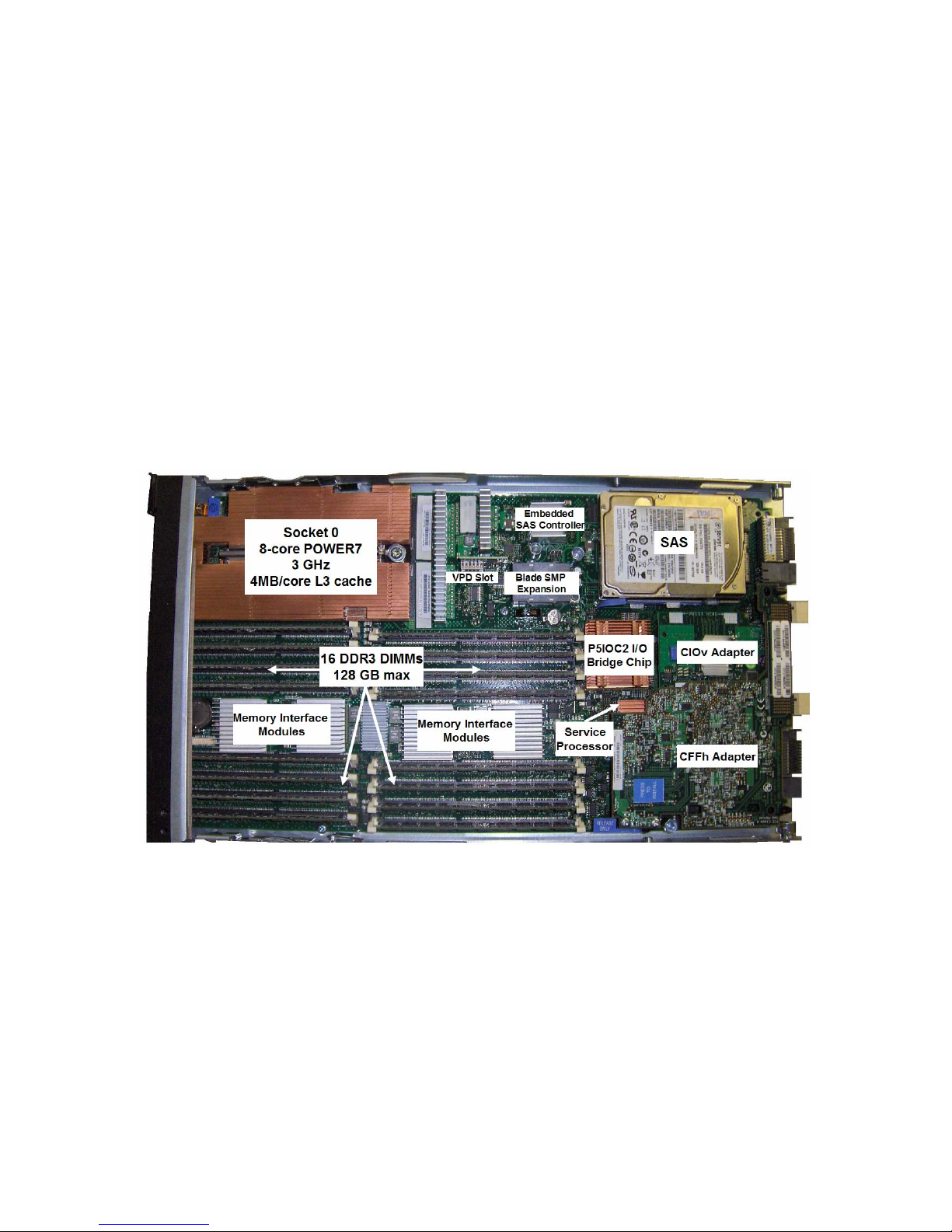
1.1.1. IBM BladeCenter PS701 Express
The IBM BladeCenter PS701 Express is a single-wide blade server based on the POWER7™
processor. The PS701 contains 1 socket and 8 POWER7™ cores, which use IBM’s 45-nm
lithography and operate at 3 GHz. The PS701 also includes 4 MB of on-chip eDRAM (enhanced
Dynamic RAM) L3 cache per core (total of 32 MB per socket) and 256 KB of L2 cache per core.
Up to 16 DDR3 memory DIMMs are supported for a maximum of 128 GB. The blade server
includes 2 embedded 1Gb Ethernet ports, onboard SAS and USB controllers, EnergyScale™
power management and an FSP-1 service processor. A maximum of one onboard Serialattached SCSI (SAS) drive is supported. The PS701 supports 2 types of I/O expansion adapters:
Combination Form Factor – Horizontal (CFFh) and Combination I/O Form Factor – Vertical
(CIOv). For IBM i, the PS701 is supported in IBM BladeCenter H and BladeCenter S. The
following picture shows the PS701, identifying the major components:
1.1.2. IBM BladeCenter PS700 Express
The IBM BladeCenter PS700 Express is a single-wide blade server based on the POWER7™
processor. The PS700 is similar to the PS701, with only the following differences:
• The POWER7™ socket contains only 4 active processor cores. The remaining 4 cores
cannot be activated via Capacity on Demand
• Two memory interface modules are present instead of 4
• Up to 8 DDR3 memory DIMMs are supported for a maximum of 64 GB
• Two SAS drives are supported
• The blade SMP connector is not present
5
Page 6

The I/O options and chassis support for IBM i for the PS700 are the same as those for the
PS701.
1.1.3. IBM BladeCenter PS702 Express
The IBM BladeCenter PS702 Express is a double-wide blade server based on the POWER7™
processor. The PS702 consists of the PS701 main blade unit and a Symmetric Multiprocessing
(SMP) expansion unit, which occupies an adjacent blade bay in an IBM BladeCenter. The PS702
has the following combined hardware characteristics:
• 2 sockets and 16 POWER7™ cores operating at 3 GHz
• 4 MB of L3 cache per core (total of 32 MB per socket) and 256KB of L2 cache per
core
• Up to 32 DDR3 memory DIMMs for a maximum of 256 GB
• 4 embedded 1Gb Ethernet ports
• Onboard SAS and USB controllers, EnergyScale™ power management and FSP-1
service processor on the main blade unit
• Up to 2 SAS onboard drives
• Up to 2 CFFh and 2 CIOv I/O expansion adapters
For IBM i, the PS702 is supported in BladeCenter H and BladeCenter S.
Note that the I/O adapter options for IBM i on PS700, PS701 and PS702 are the same as
those on JS23 and JS43.
1.1.4. IBM BladeCenter JS23 Express
The IBM BladeCenter JS23 Express is a single-wide blade server based on the POWER6™
processor. The JS23 contains 2 sockets and 4 POWER6™ cores, which use IBM’s enhan ced
65-nm lithography and operate at 4.2 GHz. The JS23 also includes 32 MB of shared L3 cache
per socket and 4 MB of dedicated L2 cache per core. Up to 8 DDR2 memory DIMMs are
supported for a maximum of 64 GB. The blade server includes 2 embedded 1Gb Ethernet ports,
onboard SAS and USB controllers, EnergyScale™ power management and an FSP-1 se rvice
processor. A maximum of one onboard Serial-attached SCSI (SAS) or Solid State Disk (SSD)
drive is supported. The JS23 supports 2 types of I/O expansion adapters: Combination Form
Factor – Horizontal (CFFh) and the new Combination I/O Form Factor – Vertical (CIOv). For IBM
i, the JS23 is supported in IBM BladeCenter H and BladeCenter S. The following picture shows
the JS23, identifying the major components:
6
Page 7

1.1.5. IBM BladeCenter JS43 Express
The IBM BladeCenter JS43 Express is a double-wide blade server based on the POWER6™
processor. The JS43 consists of the JS23 main blade unit and a Symmetric Multiproce ssing
(SMP) expansion unit, which occupies an adjacent blade bay in an IBM BladeCenter. The JS43
has the following hardware characteristics:
• 4 sockets and 8 POWER6™ cores operating at 4.2 GHz
• 32 MB of L3 cache per socket and 4 MB of L2 cache per core
• Up to 16 DDR2 memory DIMMs for a maximum of 128 GB
• 4 embedded 1Gb Ethernet ports
• Onboard SAS and USB controllers, EnergyScale™ power management and FSP-1
service processor on the main blade unit
• Up to 2 SAS or SSD onboard drives
• Up to 2 CFFh and 2 CIOv I/O expansion adapters
For IBM i, the JS43 is supported in BladeCenter H and BladeCenter S. The picture below shows
only the SMP expansion unit of the JS43, identifying the major components:
7
Page 8

1.1.6. IBM BladeCenter JS22
The JS22 Power blade is a 4-core blade server based on the POWER6™ processor. The JS22
fits in a standard IBM BladeCenter chassis and has an integrated Service Processor (SP), two
Gigabit Ethernet ports, SAS and USB controllers and a SAS disk drive. The embedded Ethernet
ports are Integrated Virtual Ethernet (IVE) ports, also present on other POWER6-based servers.
Additional I/O is provided by CFFh and CFFv expansion cards, which allow connections to
external storage and tape via switches in the BladeCenter chassis. IBM i on the JS22 is
supported in BladeCenter H and BladeCenter S. The following picture shows the JS22,
identifying the major components:
8
Page 9

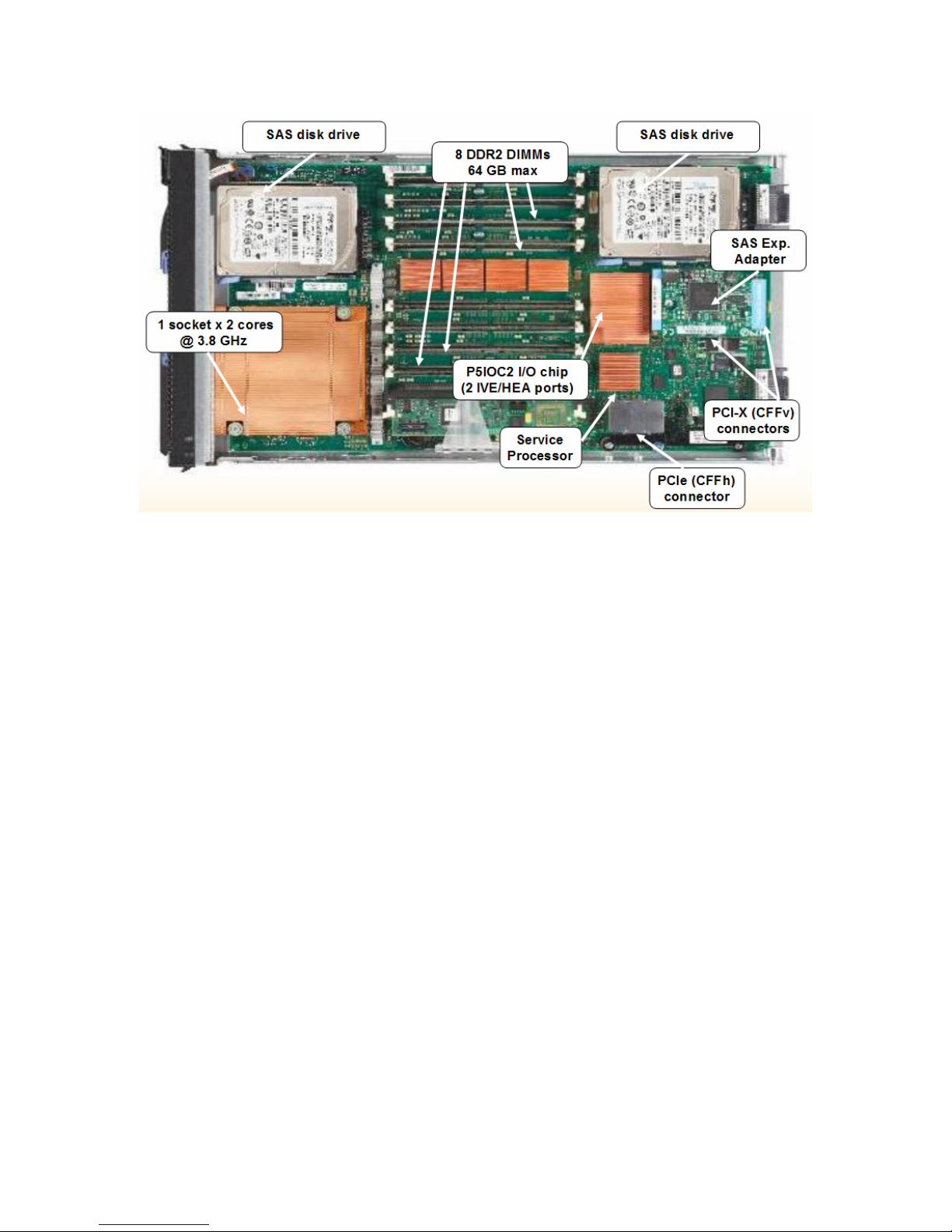
1.1.7. IBM BladeCenter JS12
The JS12 Power blade is a 2-core blade server based on the POWER6™ processor. Its
hardware is very similar to that of the JS22, with several important differences:
• There is a single POWER6 socket with 2 processor cores
• The processor cores operate at 3.8 GHz, instead of the JS22’s 4 GHz
• Two integrated SAS drives are supported on the blade
• Four additional memory DIMM slots are supported, for a total of eight slots
The JS12 includes the same SP, embedded Gigabit Ethernet (IVE) ports, CFFv and CFFh I/O
expansion slots, and embedded SAS and USB controllers. The JS12 is capable of supporting
twice the number of memory DIMMs because of the new, shorter DIMM design, which allows the
DIMMs to be plugged in vertically. IBM i on the JS12 is supported in BladeCenter H and
BladeCenter S. The following picture shows the JS12, identifying the major components:
9
Page 10
Note that all implementation instructions in the rest of the document apply to JS12, JS22,
JS23, JS43, PS700, PS701 and PS702 unless explicitly stated otherwise.
1.1.8. Logical Partitioning (LPAR)
Like other Power systems, Power blades can be partitioned into separate environments, or logical
partitions (LPARs). Power blades support IBM i, AIX and Linux partitions. Any physical hardware
the blade has access to is owned by a Virtual I/O Server (VIOS) LPAR, which virtualizes storage,
optical and network resources to the other LPARs. An IBM i LPAR on the blade does not have
direct access to any physical hardware on the blade or outside the BladeCenter chassis. IBM i is
a client to VIOS, using a Virtual SCSI (VSCSI) connection in the Hypervisor firmware residing on
the SP.
VIOS is always the first LPAR installed on a partitioned Power blade. Once VIOS is installed,
other LPARs can be created using the Integrated Virtualization Manager (IVM). IVM is part of
VIOS and provides a browser interface to the blade for managing LPARs and I/O virtualization.
The Power blade does not support a Hardware Management Console (HMC).
1.1.9. Overview of I/O concepts for IBM i on blade
IBM i LPARs on a Power blade can use Fibre Channel or SAS storage. The type of storage
used is determined by the I/O modules available in the BladeCenter chassis and the I/O
expansion adapters present on the blade, and not by the blade machine type and model.
All POWER6™ and POWER7™ processor-based blades are capable of conne cting to both Fibre
Channel or SAS storage. The JS23, JS43, PS700, PS701 and PS702 would use one of several
CIOv adapters and/or the QLogic CFFh Fibre Channel/Ethernet adapter to connect to Fibre
Channel storage; they would use the CIOv SAS passthrough adapter to connect to SAS storage.
The JS12 and JS22 would use the QLogic CFFh Fibre Channel/Ethernet adapter to connect to
10
Page 11

Fibre Channel storage and the CFFv SAS adapter to connect to SAS storage. IBM i on a blade
supports Fibre Channel and/or SAS storage (IBM DS3200) with BladeCenter H, and BladeCenter
S internal SAS storage and/or DS3200 with BladeCenter S. IBM i supports the SAS RAID
Controller I/O Module in BladeCenter S. Fibre Channel storage is not supported with
BladeCenter S.
The storage is physically connected to VIOS using a supported expansion adapter for that blade.
Once the Fibre Channel or SAS LUNs, or SAS drives in the BladeCenter S are recognized by
VIOS, they are directly virtualized to IBM i, so that each LUN or SAS drive appears as one drive
within IBM i. IBM i is installed using the DVD drive in the chassis (virtualized by VIOS) or a media
image file in VIOS.
IBM i LPARs have two different 1Gb Ethernet connectivity options, both using VIOS virtualization.
The first option is the embedded Host Ethernet Adapter (HEA) ports on the blade. HEA ports are
not directly assigned to IBM i; instead they are physical assigned to VIOS, which provides a
Virtual Ethernet Bridge for client partitions. The second option is the Ethernet ports on the
QLogic CFFh Fibre Channel/Ethernet adapter. Once again, the ports are physically attached to
VIOS, which bridges them to IBM i. In order to take advantage of the Virtual Ethernet bridge, IBM
i must have at least one Virtual Ethernet adapter. One such adapter is created for each new IBM
i partition by default.
Operations Console (LAN) is the only console option. HMC console, Operations Console – Direct
Attached, thin clients or twinaxial connections are not supported. IBM i partitions use the same
network virtualization framework explained above for both LAN console and production TCP/IP
traffic. It is recommended that two separate Virtual Ethernet adapters be created for those
functions in each IBM i partition. The two adapters can then reside on the same Virtual LAN
(VLAN), and therefore connect to the outside network using the same HEA or CFFh port.
Alternatively, each Virtual Ethernet Adapter can be on a separate VLAN and using a different
HEA or CFFh port to reach the external network.
See section 7 of this document for an explanation of the save and restore options for IBM i on
blade, as well as the procedures for saving and recovering VIOS.
The following diagram shows an example Power blade environment with 2 IBM i, 1 AIX and 1
Linux LPAR as clients of VIOS:
11
Page 12

1.2. Review terminology
BladeCenter: The chassis containing the blade servers, I/O modules, AMM, DVD-ROM drive,
Power and fan modules.
Advanced Management Module (AMM): A control module residing in a speci al I/O bay in the
BladeCenter. The AMM provides browser and command-line interfaces into the BladeCenter and
can also provide KVM (keyboard, video, mouse) functions to blade servers. The KVM functions
are not used for Power blades.
I/O bay: A slot for an I/O module (switch) inside the BladeCenter. A BladeCenter can have a mix
of standard and high-speed switch bays.
I/O module (switch): A switch residing in the BladeCenter which provides connectivity between
the blade servers and external I/O device, using wiring in the BladeCenter midplane.
Multi-switch Interconnect Module (MSIM): A module which occupies both high-speed I/O bays
7 and 8 or 9 and 10. By placing a standard “vertical” module (normally residing in I/O bays 1-4) in
an MSIM, the module can use the BladeCenter’s high-speed fabric. This allows a “horizontal”
high-speed expansion card (CFFh) to connect through a “vertical” module.
Blade server: A standalone server residing in a blade slot in the BladeCenter.
12
Page 13

Service Processor (SP): The SP on the Power blade is similar to the SP (sometimes called
“FSP”) on other POWER6-based systems. It contains firmware to manage the hardwa re on the
blade; the Power Hypervisor; and Partition Firmware (PFW).
System firmware: As with other POWER6-based systems, this is the firmware on the SP (see
above).
I/O expansion card: Sometimes called “daughter card.” An I/O adapter that fits into a PCIe or
PCI-X slot on the blade and allows connectivity to external I/O devices through the BladeCenter
midplane and I/O modules.
Combination Form Factor – Horizontal (CFFh) I/O expansion adapter: A PCIe I/O adapter
that allows access to external resources through I/O bays 7 – 10 in BladeCenter H, and bay 2 in
BladeCenter S.
Combination I/O Form Factor – Vertical (CIOv) I/O expansion adapter: A PCIe I/O adapter
that allows access to external resources through I/O bays 3 and 4 in both BladeCenter H and
BladeCenter S.
Combination Form Factor – Vertical (CFFv) I/O expansion adapter: A PCI-X I/O adapter that
allows access to external resources through I/O bays 3 and 4 in both BladeCenter H and
BladeCenter S.
Adapter firmware: The firmware on the I/O expansion cards on the blade.
Integrated Virtual Ethernet (IVE) ports: Like other POWER6-based systems, the POWER6
blade includes 2 embedded Gigabit Ethernet ports on the system I/O bridge chip.
Host Ethernet Adapter (HEA) ports: Another name for the IVE ports, more commonly used in
technical documentation.
Virtual I/O Server (VIOS): The Virtual I/O Server is software that is located in a logical partition.
This software facilitates the sharing of physical I/O resources between client logical partitions
within the system.
Integrated Virtualization Manager (IVM): A browser interface installed with VIOS. It provides
LPAR and virtualization management functions.
Virtual Ethernet adapter: A virtual network adapter created in the Power Hypervisor that is part
of an LPAR’s hardware resources. On Power blade, IBM i cannot be assigned physical network
adapters.
Virtual SCSI adapter: A virtual storage adapter created in the Power Hypervisor that is part of
an LPAR’s hardware resources. On Power blade, a Virtual SCSI (VSCSI) client adapter is
created in IBM i and a VSCSI server adapter in VIOS for storage virtualization.
Virtual Ethernet bridge: A VIOS function that allows Layer-2 bridging of a Virtual LAN to an
outside physical LAN. It is a required on Power blade in order to provide both LAN console and
standard networking to IBM i.
Logical Unit (LUN): A volume created on a SAN system that appears as a single disk device to
a server.
Disk Drive Module (DDM): A physical disk unit in a SAN system.
SDDPCM (Subsystem Device Driver – Path Control Module): A Multi-path I/O (MPIO) driv er
for certain storage subsystems installed on top of VIOS.
RDAC (Redundant Disk Array Controller): A Multi-path I/O (MPIO) driver for DS4000 or
DS5000, which is included with VIOS.
SAS (Serial-attached SCSI): A storage access protocol, which is the next generation of the
[parallel] SCSI protocol.
DSM (Disk Storage Module): A disk bay in the BladeCenter S, currently capable of supporting
six SAS or SATA drives. Two DSMs are supported in the BladeCenter S.
1.3. Supported environments
For a complete list of supported hardware, firmware and software for the IBM i on Power blade
environment, see http://www.ibm.com/systems/i/advantages/v6r1/blades/index.html.
13
Page 14

1.4. Plan for necessary IP addresses
You should plan to assign IP addresses to the following components for a minimum IBM i on
blade configuration. All the addresses below are typically configured on the same subnet.
• AMM (this IP address is already assigned on an existing BladeCenter)
o The AMM IP address is a physical LAN IP address. It will be used to remotely
manage the BladeCenter and blade servers
• Ethernet I/O module (this IP address is already assigned on an existing BladeCenter)
o This IP address will be used to connect the Ethernet I/O module to the physical
LAN, allowing any blades in the BladeCenter access to the LAN
• VIOS/IVM
o An IP address on the external LAN that will be used to connect to both IVM and
the VIOS command line
• IBM i LAN console
o An IP address on the external LAN that will be used to provide 5250 console
access to IBM i via a PC with the System i Access for Windows software. The
address will be assigned to the IBM i partition when the LAN console connection
is first established. Note that this IP address is different from the VIOS IP
address and the IP address later used for IBM i production TCP/IP traffic.
• IBM i production interface
o An IP address on the external LAN that will be used for IBM i production network
traffic. This address will be configured after IBM i is installed using LAN console.
It is recommended that the IBM i LAN console and production network interface
use two separate Virtual Ethernet adapters in the IBM i partition
• PC for LAN console and IVM browser access
o When the IBM i LAN console connection is first established, the console PC must
be on the same subnet as the IBM i partition. Once the console is established,
this restriction is removed
• SAS I/O module 1
o An IP address on the external LAN that will be used to connect to the SAS I/O
module. This IP address is required in order to manage the SAS module
configuration and assign SAS drives in the chassis to blades.
• SAS I/O module 2
o An IP address on the external LAN that will be used to connect to the SAS I/O
module. This IP address is required in order to manage the SAS module
configuration and assign SAS drives in the chassis to blades. A second SAS I/O
module is optional in the BladeCenter S.
• SAS RAID controller module 1
o This applies only to BladeCenter S. An IP address on the external LAN that
will be used to communicate specifically with the RAID subsystem in the module.
When a pair of these I/O modules is used, an IP address is also required to be
assigned to the RAID subsystem in addition to assigning an IP address to the
SAS switch component of the module.
• SAS RAID controller module 2
o This applies only to BladeCenter S. An IP address on the external LAN that
will be used to communicate specifically with the RAID subsystem in the module.
Two such modules must always be used; therefore, this IP address is required if
the RAID SAS modules are installed.
• Fibre Channel switch modules
o This applies only to BladeCenter H. An IP address on the external LAN that
will be used to communicate with a Fibre Channel switch module through the
AMM. This IP address is required for switch configuration and firmware updates.
14
Page 15
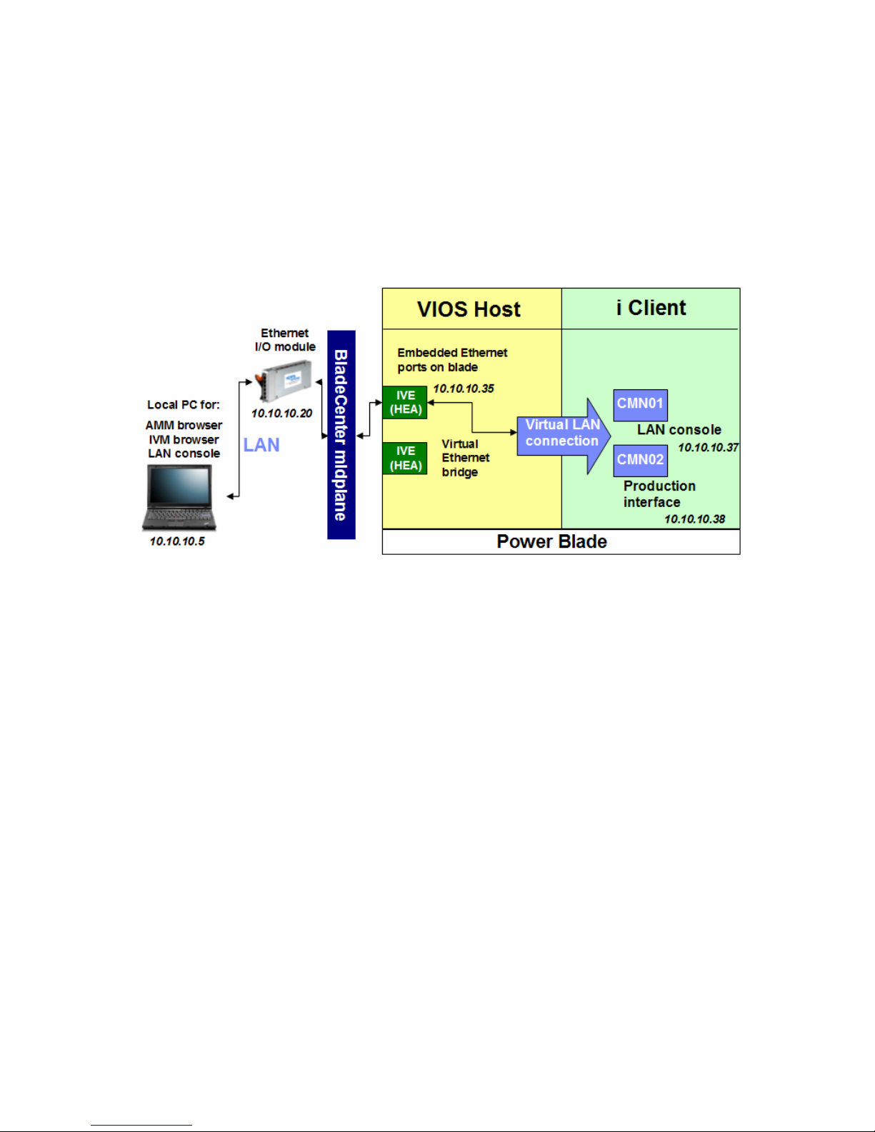
From a network perspective, one significant difference between the BladeCenter H and
BladeCenter S is that in the BladeCenter H, each embedded HEA port on the Power blade
connects to the outside LAN through a separate Ethernet module in the chassis. The first HEA
port connects through I/O module bay 1 and the second one through I/O module bay 2. In the
BladeCenter S, both HEA ports on the blade connect through I/O module bay 1. If the network
ports on the QLogic CFFh Fibre Channel/Ethernet adapter are used in a BladeCenter H, the first
one connects through I/O module bay 7 and the second through I/O module bay 9. If that
expansion adapter is used in BladeCenter S, both ports connect through I/O module bay 2. The
following diagram shows a sample network configuration for a basic IBM i on blade installation:
1.5. Install System i Access for Windows
As mentioned above, IBM i on Power blade uses LAN console for a system console. LAN
console necessitates having a PC (initially on the same subnet as VIOS and IBM i) with the
System i Access for Windows software at version 6.1 or later. The same PC can be used for
the browser connection to IVM and Telnet sessions to the AMM or VIOS. Obtain the System i
Access software version 6.1 or later by visiting this Web site:
http://www.ibm.com/systems/i/software/access/caorder.html.
Complete the PC preparations for LAN console and install the software as described in this
section of the IBM i Information Center:
http://publib.boulder.ibm.com/infocenter/systems/scope/i5os/topic/rzajr/rzajrlcnetworksu.htm.
Make sure to install the Operations Console component.
1.6. Install PuTTY
As mentioned above, IVM is used for both LPAR and virtual resource management in this
environment. IVM requires networking to be configured in VIOS, which is discussed in section
5.3. To install and configure VIOS, and later to save or restore it, a Telnet session to the AMM or
to VIOS is required. Use the PuTTY application any time a Telnet session is mentioned in this
document. PuTTY provides better terminal functionality than the Telnet client included with
Windows and can be downloaded at no cost from
http://www.chiark.greenend.org.uk/~sgtatham/putty/download.html. Install PuTTY on the same
PC used for LAN console and the browser connection to IVM.
15
Page 16

2. Prepare for the hardware installation
2.1. Verify or obtain BladeCenter hardware
If you have already purchased a BladeCenter chassis, verify it is supported for IBM i on a Power
blade by consulting the supported environments document:
http://www.ibm.com/systems/i/advantages/v6r1/blades/index.html.
If you have not already obtained a BladeCenter chassis, work with your local sales channel or
use the IBM BladeCenter chassis Web site at
http://www.ibm.com/systems/bladecenter/hardware/chassis/.
2.2. Verify or obtain I/O switch modules
If you have already obtained the BladeCenter switch modules, verify that:
• They are supported for IBM i on Power blade
• They meet the requirements of the minimum configuration for IBM i on Power blade
Consult the supported environments document at
http://www.ibm.com/systems/i/advantages/v6r1/blades/index.html.
NOTE: If the Power blade(s) is/are going to co-exist with another type of blade server, such as
Intel-based blades, verify that the I/O switch module configuration of the chassis meets the I/O
requirements of all blades.
3. Hardware installation and BladeCenter firmware updates
3.1. Assemble the BladeCenter and blade server hardware
The first step in preparing the BladeCenter is to install the BladeCenter and blade server
hardware. This may include installing any management modules, power modules, and I/O
modules in the BladeCenter. The BladeCenter might have these components already installed if
an additional blade server is being added to an already functioning BladeCenter. Before installing
the blade servers in the BladeCenter, any blade server options must be installed. This may
include additional processors (if x86 blades), additional memory and I/O expansion cards. For
Power blade servers, any required CFFh, CIOv and/or CFFv expansion adapters are installed at
this time, depending on the chassis and storage used. Refer to the blade server and expansion
card documentation that came with the option for details on installing each one. Once the blade
server options have been installed, the blade server can be installed in the BladeCenter. Refer to
BladeCenter and blade server documentation for details on how to install the BladeCenter and
blade server components. After installing all the blade server options, installing the blade servers
into the BladeCenter, and installing the BladeCenter modules, the BladeCenter can be connected
to the Power outlets.
16
Page 17

3.2. Configure the Advanced Management Module (AMM)
3.2.1. Initial AMM configuration
At this time, the AMM must have an Ethernet cable plugged into its Ethernet port. Plug the other
end of this cable into the Ethernet connector of a computer where you will open a browser
session to the AMM. In some cases, a switc h or hub may also be necessary to connect. The
following steps are performed on the computer connected to the AMM and not on the
BladeCenter console.
Set the IP address to one in the same subnet as the AMM’s default IP address of
192.168.70.125 such as 192.168.70.101 and set the subnet mask to 255.255.255.0.
Ensure the BladeCenter’s AC Power cords are plugged into an appropriate Po wer source to
provide Power for the management module. Allow about 30 seconds after performing
this step for the management module to boot
Open a Web browser on the computer connected to the AMM. In the address or URL field,
type the IP address (192.168.70.125 is the default) of the AMM to which you want to
connect
The Enter Password window will open. Type the user name and password on the Enter
Password window. The management module has a default user name of USERID and
password of PASSW0RD (where 0 is a zero, not the letter O). It is recommended to
change the password during this initial configuration
Select a timeout value on the next screen and click continue
3.2.2. AMM user profiles
To create additional user profiles on the AMM, click Login Profiles under MM Control
Click a login ID currently marked as “not used”
Enter the user profile and password (twice), select the user profile’s desired role and click
Save
3.2.3. AMM LAN configuration
To configure the AMM so that it is accessible on the local network, click Network Interfaces
under MM Control
Enter a hostname for the AMM. If the AMM is going to use DHCP, choose the option
Enabled – Obtain IP Config from DHCP server in the DHCP drop-down menu
If the AMM is going to use a static IP address, choose the option Disable – Use static IP
configuration, then enter the IP address, subnet mask and gateway IP address
Click Save.
3.3. Download BladeCenter firmware
The procedures below are performed on a computer using a common we b browser, while
accessing the Web page: http://www.ibm.com/systems/i/advantages/v6r1/blades/index.html (the
IBM i on Power Blade Supported Environments document).
Start by locating the BladeCenter chassis model
Click on the Download firmware link
The Support for BladeCenter - Downloads page will then be displayed.
Alternatively, access the Support for BladeCenter - Downloads site at this URL: http://www-
947.ibm.com/systems/support/supportsite.wss/brandmain?brandind=5000020.
17
Page 18

3.4. Download BladeCenter management module firmware
• From the Support for BladeCenter - Downloads page, in the Refine results field,
select Advanced Management Module and click the Go button
• Note that both functional and maintenance releases of the AMM firmware are
available for download. A functional release enables new functions in the
BladeCenter; whereas a maintenance release fixes known problems since the last
functional release
• Download both the latest functional and maintenance firmware releases. Verify that
the Power blade(s) and x86 blade(s) you are installing are in the Supported
systems list
• On the firmware update page, click on the link for the README text file and print a
copy for use as a reference when actually performing the update
• Click on the browser’s Back button to return to the previous page
• Click on the link for the .zip file containing the firmware updates to download the file.
This file will be used to later update the firmware
3.5. Download BladeCenter Fibre Channel I/O module firmware
• From the Support for BladeCenter - Downloads page, in the Refine results field, select
Networking and click the Go button
• Find and select the appropriate link for the Fibre Channel I/O module installed in the
BladeCenter chassis (most often Brocade or QLogic)
• On the firmware update page, click on the link for the README text file and print a copy
for use as a reference when performing the update
• Click on the browser’s Back button to return to the previous page
• Next, click on the link of the firmware update to download the file. This file will be used
later to update the firmware. This link may lead to the I/O module vendor’s Web site:
o For Brocade, fill in the export compliance form and accept the user’s license.
Then download the file marked similar to Fabric OS v5.3.0a for PC
o For Cisco, click on the latest available release, named similar to Cisco MDS
9000 SAN-OS Software Release 3.2, then click the Download Software link. A
registration with Cisco is required to download the update file
o For QLogic, find the table named Fibre Channel Switch Module Firmware and
download the latest version of the firmware marked similar to QLogic 4Gb 6-
Port Fibre Channel Switch Module for IBM eServer BladeCenter Firmware
3.6. Download BladeCenter Ethernet I/O module firmware
• From the Support for BladeCenter - Downloads page, in the Refine results field,
select Networking
• Find and select the appropriate link for the Ethernet I/O module installed in the
BladeCenter chassis
• On the firmware update page, click on the link for the README text file and print a
copy for use as a reference when performing the update
• Click on the browser’s Back button to return to the previous page
• Next, click on the link of the firmware update to download the file. This file will be
used later to update the firmware
3.7. Download BladeCenter SAS I/O module firmware
• Start at http://www.ibm.com/support
and press the Go button
18
Page 19

• Choose BladeCenter under Choose support type and click the right arrow
• Select BladeCenter S under Product family and click Go. This applies even if you are
using one or both SAS I/O modules in a BladeCenter H
• If using the standard SAS I/O module, find the link to the most recent SAS Connectivity
Module firmware and click it
o Download the .ZIP file containing the firmware update and the corresponding
README file
• If using the SAS RAID I/O module, find the link to the most recent SAS RAID Controller
Module Matrix and click it
o Click the Storage Configuration Manager (SCM) Firmware Update Package
link
o Download the .ZIP and README files
o Go back to the SAS RAID Controller Module Matrix page and also download
the latest version of the Storage Configuration Manager software; you will
employ it later to configure RAID arrays and volumes
3.8. Download the BladeCenter S DSM firmware
• Start at http://www.ibm.com/support
• Choose BladeCenter under Choose support type and click the right arrow
• Select BladeCenter S under Product family and click Go
• Find the link to the most recent Disk Storage Module (DSM) Firmware and click it
• Download the .ZIP file containing the firmware update and the corresponding
README file
3.9. Update the BladeCenter management module firmware
• You can begin this procedure from any AMM Web browser window
• Click Firmware Update under MM Control on the navigation pane on the left
• On the Update MM Firmware window, select Browse and navigate to the location
(usually on a local PC) where you downloaded the management module firmware update.
The file or files will have an extension of .PKT
• Begin with the update file for the functional AMM firmware release. Highlight the file
and click the Open button
• The README text may specify a particular order to select these files. If so, follow the
README file instructions
• The full path of the selected file is displayed in the Browse field
• To start the update process, click Update
• A progress indicator opens as the file is transferred to temporary storage on the AMM. A
confirmation window will be displayed when the file transfer is complete
• Verify that the file shown on the Confirm Firmware Update window is the one you want
to update. If not, click Cancel
• To complete the update process, click Continue. A progress indicator opens as the
firmware on the AMM is flashed. A confirmation window will be displayed when the
update has successfully completed
• The README file text might direct you to restart the AMM after completing the .PKT file
update. If so, click Restart MM on the navigation pane on the left side of the window
• Click OK to confirm the reset. The Web browser window will then close. A new Web
browser window will have to be started and signed onto to continue
• Repeat this process using the update file for the latest maintenance firmware release
19
Page 20

3.10. Update the firmware on the BladeCenter I/O modules
Each of the I/O module’s software needs to be updated at this time. The procedure varies
depending on the manufacturer of the I/O module. Refer to the README file downloaded earlier
along with the I/O module to complete this task. Make sure you are using the instructions for
VIOS or AIX in each README; avoid instructions that refer to SANsurfer on Linux or Windows.
3.10.1. Assigning an IP address to I/O modules
Instructions in the README files assume that the I/O module you are updating is accessible on
the network. To assign an IP address to an I/O module:
• Log into the AMM browser UI with an administrator ID
• Click I/O Module Tasks
• Click Configuration
• Scroll down to the correct I/O module, change the network settings and click Save
• If using the SAS RAID module, make sure to change the network settings for both the
SAS switch component and the RAID subsystems
3.11. Update the firmware on the BladeCenter S DSM(s)
Use the instructions in the README file you downloaded in section 3.8. If the BladeCenter S
contains two DSMs, make sure to update the firmware on both. Note that to update the DSM
firmware, you log into one of the SAS I/O modules. The default userid for a SAS I/O module is
USERID and the default password is PASSW0RD (note the number zero). To log into a SAS I/O
module, start a browser session to the IP address assigned to it. If an IP address has not been
assigned to a SAS I/O module yet, follow these instructions to do so:
• Start a browser session to the IP address of the AMM
• Log in with an administrator userid
• Under I/O module Tasks, click Configuration
• Locate the SAS I/O module and assign an IP address, subnet mask and gateway. Click
Save
• Repeat for the second SAS module, if it is installed
• Continue by following the DSM firmware update instructions in the README file you
downloaded in section 3.8
3.12. Installing and configuring an Intelligent Copper Pass-through Module (ICPM)
Use the instructions in the ICPM Installation Guide
(http://publib.boulder.ibm.com/infocenter/bladectr/documentation/topic/com.ibm.bladecenter.io_44
W4483.doc/44r5248.pdf).
4. Storage management
As mentioned previously, the type of storage IBM i can use on a Power blade depends on the
BladeCenter in which the blade is installed, the I/O modules available in the chassis and the
expansion adapters present on the blade. IBM i on all Power blades supports Fibre Channel and
SAS storage (DS3200) connected to BladeCenter H and SAS storage only in BladeCenter S
20
Page 21
(internal drives and/or DS3200). IBM i on all Power blades supports the SAS RAID Controller
module in BladeCenter S; that module is not supported in BladeCenter H. Fibre Channel storage
in BladeCenter S is not supported for IBM i. This section will examine storage concepts for
BladeCenter H first, followed by those for BladeCenter S.
4.1. Storage concepts for IBM i on Power blade in BladeCenter H
In the Power blade environment, IBM i partitions do not have direct access to any physical I/O
hardware on the blade, in the chassis or outside the BladeCenter. In BladeCenter H, disk storage
is provided by attaching LUNs on a Fibre Channel or SAS storage subsystem to VIOS, then
directly virtualizing them to IBM i using the Integrated Virtualization Manager (IVM). DVD access
for IBM i installation is provided by assigning the DVD-ROM drive in the BladeCenter to a blade,
which makes the optical drive available to VIOS. The drive is then directly virtualized to IBM i by
assigning it in IVM. Direct virtualization of the TS2240 LTO4 SAS-attached tape drive is also
supported: the drive is attached to a SAS I/O module in the chassis. Once available in VIOS, the
tape drive is assigned to an IBM i partition in IVM.
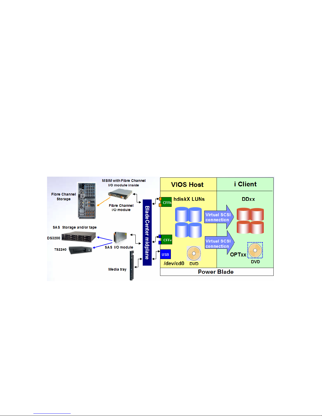
4.1.1. Storage concepts for JS12 and JS22 in BladeCenter H
The following diagram presents an overview of storage, optical and tape virtualization for IBM i on
JS12 and JS22 in BladeCenter H:
VIOS accesses Fibre Channel storage via the CFFh expansion card on the blade. Presently, the
QLogic CFFh card has 2 x 4Gb Fibre Channel ports and 2 x 1Gb Ethernet ports. Before reach ing
the external SAN, disk I/O operations first travel through the BladeCenter midplane; then through
a Multi-switch Interconnect Module (MSIM) and a SAN I/O module inside the MSIM. The MSIM
resides in slots 7 and 8, or 9 and 10 in the BladeCenter H chassis. The MSIM allows the
standard, or “vertical,” SAN module inside it to connect to a high-speed, or “horizontal,” CFFh
card on the blade. With the 2-port CFFh card, 2 MSIMs with 1 SAN module in each are
supported in the BladeCenter H for redundancy in the SAN connection.
When configuring Fibre Channel LUNs for IBM i (via VIOS) in this environment, the host
connection on the SAN system must include the World-wide Port Name (WWPN) of one or both
ports on the CFFh card. If the Power blade is inserted in the chassis, the WWPNs can be
observed in the AMM using the following steps:
21
Page 22

• Log into the AMM browser UI with an administrator ID
• Click Hardware VPD
• Locate the blade with which you are working
• The CFFh card will appear as a High Speed Expansion Card with a description of
CFFH_EF HSEC. Click it
• Click the Ports tab
• Under High Speed Expansion Card Unique IDs, ID 2 is the WWPN of the first FC port
and ID 4 is the WWPN of the second FC port
When configuring LUNs for IBM i (virtualized by VIOS), they should be created as 512-byte,
“AIX” LUNs, not as 520-byte “IBM i” LUNs. VIOS accesses the 512-byte LUNs as described
above and then virtualizes them to IBM i via a Virtual SCSI connection between the 2 partitions.
The Virtual SCSI server adapter in VIOS and Virtual SCSI client adapter in IBM i are created
automatically when the LUNs are assigned to IBM i in IVM. The Virtual SCSI client adapter driver
allows IBM i to access 512-byte virtual disks. For each 4-kilobyte memory page, nine 512-byte
sectors are used, instead of eight; the ninth sector is used to store the 8-byte headers from the
preceding eight sectors.
VIOS accesses SAS storage (DS3200) using the CFFv SAS expansion adapter. The CFFv card
requires at least one SAS I/O module in bay 3, but can use two for redundancy, in bays 3 and 4.
Similar to Fibre Channel, the host connection on the SAS storage subsystem must include the
SAS IDs of the two ports on the expansion adapter. To find out those IDs in the AMM, follow
these steps:
• Log into the AMM browser UI with an administrator ID
• Click Hardware VPD
• Locate the blade with which you are working
• The CFFv SAS card will appear as an Expansion Card with a description of SAS
Expansion Option. Click it
• Click the Ports tab
• Under Expansion Card Unique IDs, ID 1 is the SAS ID of the first port and ID 2 is the
SAS ID of the second port
There is at least one Virtual SCSI connection between VIOS and each IBM i partition, which is
also used for IBM i access to the USB DVD-ROM drive in the chassis. The IVM Web interface
creates a single Virtual SCSI client adapter for each IBM i partition. The Virtual SCSI connection
allows a maximum of 16 disk and 16 optical devices in IBM i. This means that by default, a
maximum of 16 LUNs can be virtualized by VIOS per IBM i partition using only the IVM Web
interface. Additional Virtual SCSI client adapters can be created in an IBM i partition using the
VIOS command line. Note that even if only 16 LUNs are assigned to an IBM i partition, each LUN
does not represent a single physical disk arm. IBM i (via VIOS) takes advantage of the SAN
system’s ability to create a LUN using a RAID rank with multiple physical drives (DDMs).
4.1.2. Storage concepts for JS23, JS43, PS700, PS701 and PS702 in BladeCenter H
The following diagram presents an overview of storage, optical and tape virtualization for IBM i on
JS23, JS43, PS700, PS701 and PS702 in BladeCenter H:
22
Page 23
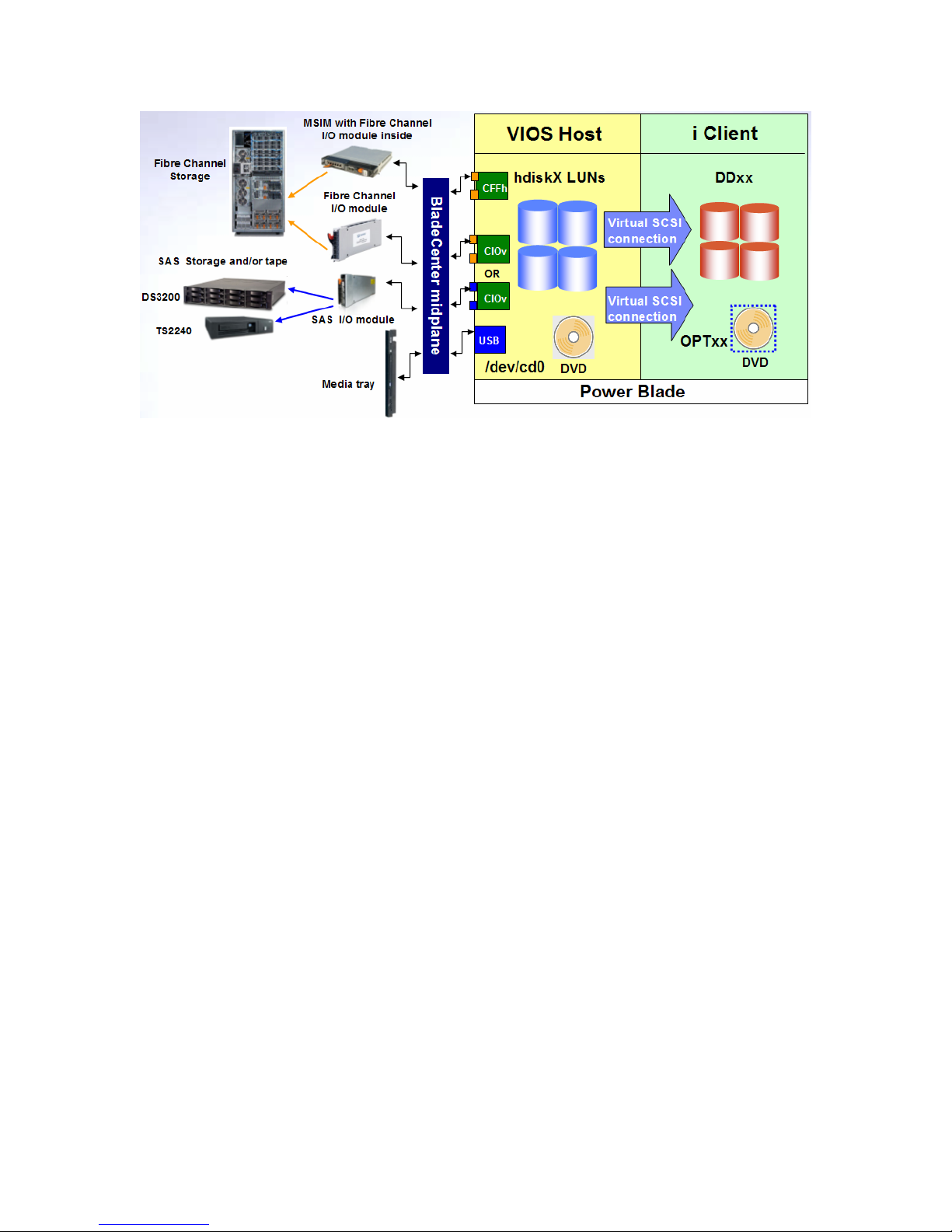
Both Fibre Channel and SAS storage concepts for JS23, JS43, PS700, PS701 and PS702 in
BladeCenter H are similar to those for JS12 and JS22, with the following differences:
• To connect to Fibre Channel storage, there are several CIOv and one CFFh expansion
adapter options. CIOv and CFFh Fibre Channel cards can be used together on the same
blade to provide adapter redundancy. CIOv adapters connect to I/O modules in bays 3
and 4
• CIOv Fibre Channel cards appear as Expansion Card with a description of Fibre
Channel EC under Hardware VPD in the AMM
• CIOv Fibre Channel adapters’ WWPNs are identified as IDs 1 and 2 on the Ports tab of
the Hardware VPD page for the adapter
• To connect to SAS storage, JS23, JS43, PS700, PS701 and PS702 use the CIOv SAS
passthrough adapter. As with Fibre Channel CIOv cards, it connects through I/O
modules in bays 3 and 4
• The CIOv SAS passthrough card appears as Expansion Card with a description of SAS
Conn Card under Hardware VPD in the AMM
4.2. Best practices for BladeCenter H and Fibre Channel storage
When configuring LUNs for IBM i (virtualized by VIOS), follow the best practices outlined in
chapter 14.5 of the latest Performance Capabilities Reference manual, available here:
http://www.ibm.com/systems/i/solutions/perfmgmt/resource.html. Note that some of its
recommendations apply only to IBM i using virtual storage outside of the blade environment.
In addition to the guidelines in the Performance Capabilities Reference manual, follow these
additional recommendations:
• Use Fibre Channel (FC) or SAS drives (and not SATA or FATA) to create the RAID ranks
for production IBM i workloads
• Use 15K RPM drives for medium and heavy I/O IBM i workloads, and 10K RPM drives for
low I/O workloads
• When creating a host connection to the WWPN of the Fibre Channel card on the blade,
specify at most 2 specific host ports. Do not create the connection so that the Fibre
Channel adapter can connect to all host port on the storage subsystem, which is the
default for some subsystems.
23
Page 24

• Once the LUNs that will be virtualized to IBM i have reported in VIOS, change their queue
depth to improve performance. Start a Telnet session to VIOS and log as padmin. Use
the following command for each LUN (hdisk1 in this example):
o chdev -dev hdisk1 -perm -attr queue_depth=32
• Another parameter that can improve performance is the number of I/O commands to
send to the QLogic CFFh Fibre Channel adapter. The recommended value is 512. Be
sure to change the value for both ports of the CFFh adapter:
o chdev –dev fcs0 –attr num_cmd_elems=512 –perm
o chdev –dev fcs1 –attr num_cmd_elems=512 –perm
• To improve reliability, enable dynamic tracking for the LUNs virtualized to IBM i. Do so
for both ports of the CFFh adapter:
o chdev –dev fscsi0 –attr dyntrk=yes –perm
o chdev –dev fscsi1 –attr dyntrk=yes –perm
Using the –perm option in the above commands means that the value will be updated only in the
VIOS device configuration database (ODM). To make the change effective, reboot VIOS when
there is downtime available for all client partitions.
4.3. Create LUNs for the IBM i partition(s) in BladeCenter H
To create LUNs for IBM i (virtualized by VIOS) on DS3400, follow the instructions in chapter 8 of
the Redbook IBM System Storage DS3000: Introduction and Implementation Guide (SG2 47065),
available here: http://www.redbooks.ibm.com/redpieces/abstracts/sg247065.html?Open.
To create LUNs for IBM i (virtualized by VIOS) on DS3950, DS4700, DS4800, DS5020, DS5100
or DS5300, follow the instructions in chapter 3 of the Redbook IBM Midrange System Storage
Implementation and Best Practices Guide (SG246363), available here:
http://www.redbooks.ibm.com/redbooks/pdfs/sg246363.pdf
To create LUNs for IBM i (virtualized by VIOS) on DS8000, follow the instructions in section 3 of
the Redbook IBM System Storage DS8000 Series: Architecture and Implem entation (SG246786),
available here: http://www.redbooks.ibm.com/redpieces/abstracts/sg246786.html?Open.
To create LUNs for IBM i (virtualized by VIOS) on the SAN Volume Controller (SVC), follow the
instructions in section 10 of the Redbook Implementing the IBM System Storage SAN Volume
Controller V4.3 (SG246423), available here:
http://www.redbooks.ibm.com/abstracts/sg246423.html?Open.
To create LUNs for IBM i (virtualized by VIOS) on the XIV storage subsystem, follow the
instructions in Chapter 4 of the Redbook IBM XIV Storage System: Architecture, Implementation,
and Usage (SG247659), available here:
http://www.redbooks.ibm.com/abstracts/sg247659.html?Open.
4.4. Multi-path I/O (MPIO) for IBM i in BladeCenter H
MPIO refers to the capability of an operating system to use two separate I/O paths to access
storage, typically Fibre Channel or SAS. For IBM i on blade, that capability resides with VIOS,
because IBM i is not directly accessing the SAN. Additionally, IBM i does not currently support
having two paths to the virtual disk units (LUNs) in VIOS from a virtual client/server perspective.
.
24
Page 25

JS12 and JS22 can achieve a level of redundancy with Fibre Channel storage by using both ports
on the CFFh adapter and a pair of MSIMs and Fibre Channel switch modules. The I/O
redundancy from the two ports on the adapter can be extended by connecting to separate
external Fibre Channel switches or directly to separate ports on the storage subsystem. Similarly,
both ports on the CFFv SAS adapter and two SAS modules can be used to achieve a level of
redundancy with SAS storage.
JS23, JS43, PS700, PS701 and PS702 support this level of MPIO by using both ports on a CFFh
or CIOv adapter. These blade servers can also achieve adapter-level redundancy with Fibre
Channel storage by employing both a CFFh and a CIOv card simultaneously. To complete such
a configuration, two MSIMs and two Fibre Channel modules in I/O bays 8 and 10 would be
required, as well as two Fibre Channel modules in bays 3 and 4.
4.4.1. MPIO drivers
VIOS includes a basic MPIO driver, which has been the default instead of the RDAC driver since
November 2008. The MPIO driver can be used with any storage subsystem which VIOS
supports and is included in a default install. In this case, configuration is required only on the
storage subsystem in order to connect a single set of LUNs to both ports on a Fibre Channel
adapter owned by VIOS.
VIOS also supports the Subsystem Device Driver – Path Control Module (SDDPCM) for certain
storage subsystems. Examples of supported subsystems include the SAN Volume Controller
(SVC) and IBM DS8000. To find out whether a particular storage system supports SDD-PCM for
VIOS, consult its interoperability matrix on the SDDPCM Web site:
http://www.ibm.com/support/docview.wss?uid=ssg1S4000201. Note that there are separate
support statements for AIX and VIOS. If SDDPCM is supported on your storage subsystem for
VIOS, download and install the driver following the instructions in the Multipath Subsystem
Device Driver User's Guide at the same location.
4.5. Storage concepts for IBM i on Power blade in BladeCenter S
As with the BladeCenter H, IBM i does not have physical access to storage when running in the
BladeCenter S. In this case, storage is provided in the chassis itself in the form of one or two
Disk Storage Modules (DSMs), each containing up to 6 SAS drives and/or SAS-attached external
storage in the IBM DS3200. While SATA drives can also be placed in the DSMs and are
supported for IBM i, they are not recommended because of their performance and reliability
characteristics. The minimum SAS configuration in the BladeCenter S is one DSM with one SAS
drive or one SAS Connectivity Module and DS3200.
IBM i supports both types of SAS I/O modules that can be placed in BladeCenter S: the SAS
Connectivity Module (switch functionality only) and the SAS RAID Controller Module (switch and
RAID functionality). However, the two types of SAS modules allow for different storage support:
• The SAS Connectivity Module does not support hardware RAID for the drives in the
chassis and supports attachment to DS3200, which provides its own RAID functions
• The SAS RAID Controller Module supports hardware RAID for the drives in the chassis,
but does not support attachment to DS3200
Note that whether RAID functionality is provided by DS3200 through the non-RAID SAS module
or by the RAID SAS module, it is independent of the SAS expansion adapter on the blade.
Neither the CFFv SAS expansion card nor the CIOv SAS expansion card supports RAID itself.
Neither card has any read or write cache.
25
Page 26

4.5.1. Storage concepts for JS12 and JS22 in BladeCenter S
The following diagram presents an overview of storage, optical and tape virtualization for IBM i on
JS12 and JS22 in BladeCenter S:
JS12 and JS22 use the CFFv SAS expansion adapter to access the following storage resources:
• SAS drives in BCS and/or LUNs from DS3200 if there is at least one non-RAID SAS
module present in the chassis
• LUNs from one or more RAID arrays internal to the chassis require both RAID SAS
modules to be present
Once SAS drives or LUNs have been assigned to the Power blade, they become available in
VIOS as hdiskX devices. VIOS then virtualizes each hdiskX disk directly to the IBM i client
partition(s), exactly as with LUNs in the BladeCenter H. Each virtualized SAS drive or LUN is
recognized and used in IBM i as a DDxx physical drive. If both internal drives are ordered on the
JS12, they will be recognized by VIOS as hdisk0 and hdisk1. The internal drives on the blade are
used for VIOS and are not virtualized to IBM i client LPARs. Access to the DVD-ROM drive in the
BladeCenter S is also provided by VIOS, as with the BladeCenter H.
4.5.2. Storage concepts for JS23, JS43, PS700, PS701 and PS702 in BladeCenter S
JS23, JS43, PS700, PS701 and PS702 follow the same storage concepts as the JS12 and JS22
in BladeCenter S, with the exception of the CFFv expansion adapter; instead, they use the CIOv
expansion card. The following diagram presents an overview of storage, optical and tape
virtualization for IBM i on JS23, JS43, PS700, PS701 and PS702 in BladeCenter S:
26
Page 27

4.6. Best practices for BladeCenter S and SAS storage
For performance information on IBM i in BladeCenter S, see section 14.5 of the latest
Performance Capabilities Reference manual, available here:
http://www.ibm.com/systems/i/solutions/perfmgmt/resource.html.
4.6.1. Best practices when using the SAS Connectivity Module
Because the SAS Connectivity Module does not support RAID, there are two possibilities for disk
protection once SAS drives in the chassis have been assigned to the Power blade and are
available in VIOS:
• Use Logical Volume Manager (LVM) mirroring in VIOS, create a volume group from the
available SAS drives, then create logical volumes and present those to IBM i
• Directly virtualize each SAS drive to IBM i and use mirroring in IBM i
The recommendation is to use mirroring in IBM i. Using logical volumes extends the path of
each I/O request in VIOS by involving the LVM layer. Mirroring in IBM i allows the use of existing
IBM i disk management skills.
For a higher level of redundancy, it is strongly recommended to assign the same number of SAS
drives in each DSM and mirror between them in IBM i. SAS drives in the BladeCenter S are
assigned to blades by changing the configuration of the SAS I/O module.
In the case of using LUNs from DS3200, they are already benefiting from RAID protection in the
external storage subsystem. Each LUN should once again be virtualized directly to IBM i in VIOS.
4.6.2. Best practices when using the SAS RAID Controller Module
The recommendation to directly virtualize LUNs to IBM i instead of using storage pools in VIOS
applies in this case, as well. Furthermore, it is strongly recommended that LUNs for IBM i on
a Power blade are created on a separate RAID array in the chassis. The goal is to avoid disk
arm contention between IBM i and other production workloads on the same or other blade s in the
BladeCenter S. While this approach lessens the flexibility of RAID array and LUN creation using
the RAID SAS module, it helps ensure the necessary response time and throughput demanded
27
Page 28

by IBM i production workloads. As with other storage subsystems, the number of physical drives
in the RAID array also plays a significant role, with a higher number of drives improving
performance.
4.7. Configuring storage in BladeCenter S using the SAS Connectivity Module
4.7.1. SAS I/O modules configurations
The configuration of the SAS I/O module(s) in the BladeCenter S determines which SAS drives in
the DSM(s) are assigned to which blades. This configuration is kept on non-volatile storage in
the module(s). If two modules are present, it is necessary to change the SAS drive assignment in
only one of them; the changes will be replicated to the second one.
8 pre-defined configurations and 4 user-defined configurations are stored on a SAS I/O module.
To use a pre-defined configuration, it has to be activated by interacting with the module. Userdefined configurations are blank until explicitly created. The following tables summarize the predefined configurations.
Pre-defined configurations for a single SAS I/O module:
Pre-defined configurations for two SAS I/O modules:
Notice that the same four configurations of drives and blades are used for both a single SAS I/O
module and two modules. Any of the four configurations can be used for IBM i in BladeCenter S.
However, keep in mind the further mirroring required in IBM i. Therefore, pre-defined
configuration #02/#03 will likely not be applicable to the majority of IBM i in BladeCenter S
implementations, because it provides for only one mirrored pair of drives in IBM i.
28
Page 29

The choice among the remaining configurations depends on the number of blades (Power and
x86) in the chassis. For example, configuration #04/#05 provides the greatest number of arms for
a single IBM i partition on the blade (12); however, it does not leave any drives in the chassis for
other blades. One approach to addressing the disk requirement for x86 blades in this case is to
use the two supported embedded drives on the x86 blade, provided they allow for sufficient disk
performance for the x86 application. If ordered, the two embedded SAS drive on the Power blade
are used to install and mirror VIOS.
Tape virtualization does not impact the choice of a pre-defined zone configuration: all pre-defined
configurations assign all external ports to all blades. Therefore, an administrator can connect a
TS2240 tape drive to any external port on a SAS I/O module and VIOS will recognize and
virtualize the drive to IBM i; provided that the blade has a CFFv or CIOv SAS expansion adapter.
4.7.2. Activate a pre-defined SAS I/O module configuration
If one of the pre-defined drive configurations fits the storage requirements of the IBM i in
BladeCenter S implementation, the only required action to assign drives to the blade is to activate
that configuration. The simplest method is to use an already familiar interface – a browser
session to the AMM:
• Start a browser session to the AMM of the BladeCenter S and sign on with USERID or
another administrator ID
• Click Configuration under Storage Tasks
• Click the SAS I/O module you want to configure. If two modules are present, it is
necessary to activate the selected configuration on only one
• Click the radio button next to the pre-defined configuration you wish to activate
• Click the Activate Selected Configuration button at the bottom of the right screen pane
The selected number of SAS drives is now available to VIOS on the Power blade to virtualize to
IBM i. There are three other methods to activate a pre-defined configuration:
• A Telnet command-line interface to the SAS I/O module
• A browser session directly to the module
• The Storage Configuration Manager GUI from a PC
However, using the AMM is the most straightforward way to just activate a pre-defined
configuration. The AMM does not have the capability to create a custom user configuration for
the SAS drives in the chassis.
4.7.3. Create a custom SAS I/O module configuration
If none of the pre-defined configurations meets the storage requirements of the IBM i in
BladeCenter S implementation, a custom drive configuration must be created by changing one of
the four available user-defined configuration templates on the SAS I/O module(s). Two interfaces
are available for creating a custom configuration:
• A Telnet command-line interface to the SAS I/O module
• The Storage Configuration Manager GUI from a PC
It is recommended to use the Storage Configuration Manager (SCM), unless you are already
familiar with the SAS I/O module command line. SCM can be downloaded here: https://www-
304.ibm.com/systems/support/supportsite.wss/docdisplay?lndocid=MIGR5502070&brandind=5000008.
29
Page 30

To install SCM and create a custom SAS I/O module configuration, follow the instructions in
chapter 4.4 of the Redpiece Implementing the IBM BladeCenter S Chassis (REDP-4357),
available here: http://www.redbooks.ibm.com/abstracts/redp4357.html?Open. When installing
SCM, choose to install only the SAS Module in BCS option.
Because custom SAS zone configurations are created from a blank slate, special care must be
taken if VIOS is going to virtualize tape to IBM i. All blades that require access to the tape drive
must specifically be configured to access the external port on the I/O module to which the tape
drive is connected.
Note that if the SAS I/O module configuration is changed after VIOS has been installed on a
Power blade, the cfgdev command must be run on the VIOS command line to detect any
changes in the drive configuration.
4.8. Configuring storage in BladeCenter S using the SAS RAID Controller Module
The SAS RAID Controller Module, also known as the RAID SAS Switch Module (RSSM),
provides RAID support for IBM i when using only the drives in a BladeCenter S. Before
continuing with the configuration steps, review the best practices for this environment in section
4.6.2. There are two general steps involved in assigning RAID storage in the chassis to a Power
blade; once available to the blade and VIOS, the LUNs are virtualized to IBM i as described in
section 5.10. The two high-level steps are:
• Use the correct SAS switch zoning configuration so that the Power blade is allowed
access to the RAID subsystem in the RSSM
• Create the appropriate configuration in the RAID subsystem and assign the new LUNs to
the Power blade
4.8.1. SAS zoning for RSSM
With a new BladeCenter S, the correct SAS zone to allow all blades access to the RAID
subsystem in the RSSM is already in place: the default pre-defined zone configuration gives all 6
blade slots access to the RAID controller and to all external SAS ports. As with the non-RAID
SAS switch modules (NSSMs), the SAS zone configuration is replicated between the two RSSMs.
If a change is required, it need be made only to one of the two RSSMs. To check whether the
default zone configuration is active on the RSSMs, use the AMM browser interface:
• Log into the AMM with an administrator ID
• Click Storage Tasks and then Configuration
• Pre-defined Config 10 should be active on both RSSMs
A user-defined configuration can also be used to limit which blades can access th e RAID
subsystem or a certain external SAS port. As with NSSM, the Storage Configuration Manager
(SCM) is used to manage zoning in the RSSM. Additionally, SCM is the interface used to create
the RAID configuration. See the next section on using SCM with RSSM.
4.8.1. Configuring RSSM with SCM
Download the latest version of SCM from this URL: https://www-
304.ibm.com/systems/support/supportsite.wss/docdisplay?lndocid=MIGR5502070&brandind=5000008. Install the interface using the instructions in chapter 4.4 of the
Redpiece Implementing the IBM BladeCenter S Chassis (REDP-4357), available here:
http://www.redbooks.ibm.com/abstracts/redp4357.html?Open. Make sure to perform a full
installation with all the management options.
30
Page 31

Once SCM is started, follow these steps to add your RSSMs to the interface:
• Sign on with a local Windows ID and password. You are not signing onto the RSSMs yet
• Expand BC-S SAS RAID Module and then Health
• Click All Resources
• Click Add SAS RAID Modules
• Enter the IP address of the SAS switch component of the RSSM in I/O bay 3
o Both the SAS switch and the RAID subsystem in both RSSMs must have
external IP addresses assigned. See section 3.10.1 for instructions
• Enter an ID and password for both the SAS switch and the RAID subsystem of the RSSM
in I/O bay 3
o The defaults for the SAS switch are USERID and PASSW0RD
o The defaults for the RAID subsystem are USERID1 and PASSW0RD
• Optionally, enter a nickname for these RSSMs
• Click OK
In most cases, it is not necessary to create a custom SAS zone configuration. If you do need to
create one, use the steps immediately below (otherwise, skip to the next set of bullets):
• Use the radio button to select the SAS switch in bay 3
• In the drop-down menu above, select Configuration, then SAS Zoning…
• Follow the instructions in chapter 4.4 of the Redpiece Implementing the IBM BladeCenter
S Chassis (REDP-4357), available here:
http://www.redbooks.ibm.com/abstracts/redp4357.html?Open
To create the RAID array and LUN configuration, follow these steps:
• On the All Resources screen, select the RAID subsystem
• In the drop-down menu above, select Configuration, then Storage…
• Click the Storage Pools tab. Storage pools are the RAID arrays you can create in the
chassis using the RSSM
• Click Create Storage Pool…
• Select Manually choose drives (advanced) and click Next
• Select the correct SAS drives (preferably in both DSMs) and RAID level for this storage
pool, then click Next
• Create the correct number of LUNs (volumes) with the correct capacity and add them to
the list of new volumes. Then click Next
• All blades that contain a CFFv or CIOv SAS expansion card and are allowed to access
the RAID subsystem will be identified in the Select Hosts area
o If your blade is not identified, click Discover Hosts
o If the blade still does not appear, check the SAS zoning configuration and
whether the SAS adapter on the blade is installed and operational
• Click your blade in the Select Hosts area
• Click on all LUNs that should be attached to that blade in the Select Volumes area
• Click Map Volumes. This action will map the selected LUNs to both ports on the SAS
expansion card. The maximum number of LUNs per blade is 8
• Click Next and then Finish
If VIOS is already running on the blade, use the cfgdev command on the VIOS command line to
recognize the new LUNs.
31
Page 32

4.9. Using the DVD drive in the BladeCenter with VIOS and IBM i
As mentioned above, VIOS virtualizes the DVD drive in the media tray (MT) of the BladeCenter to
IBM i. When the MT is assigned to the blade using the steps described in section 5.2.1, the DVD
drive becomes physically available only to VIOS. It is then assigned to an IBM partition using the
IVM GUI as described in section 7.3.2 (cd0 is the name of the physical DVD drive).
When the DVD drive must be reassigned to another IBM i LPAR on the same blade, the OPTxx
device in IBM should first be varied off. Then the cd0 device would be assigned to the second
LPAR using the same method described in section 7.3.2.
When the DVD drive must be reassigned to another IBM i LPAR on a different blade, or after it
has been used by a different blade and must be assigned back to the same LPAR, use the
following process:
• Vary off the OPTxx device in IBM i (if it was assigned to a Power blade and an IBM i
LPAR)
• Use the AMM browser interface to assign the MT to the correct blade, as described in
section 5.2.1
• Telnet to VIOS on the correct blade and sign in with padmin
• Enter cfgdev and press Enter
• Assign the DVD drive in the MT (cd0) to the correct IBM i partition on the blade, as
described in section 7.3.2.
• Vary on the OPTxx device in IBM i
Note that you must run the cfgdev command every time the DVD drive is assigned to a Power
blade, in order for VIOS to recognize that the device is present again.
4.9.1. USB 2.0 access
In October 2009, IBM enhanced the capabilities of Power blades when using the DVD drive in the
Media Tray (MT) in BladeCenter S and BladeCenter H. VIOS now uses a USB 2.0 driver for
physical access to the DVD drive. As a result, all client LPARs using the DVD drive as a virtual
optical device from VIOS can perform faster reads and writes. One benefit of this enhancement
is shorter install times for the IBM i Licensed Internal Code (LIC) and operating environment, as
well as Program Temporary Fixes (PTFs).
4.9.2. Writing to DVD-RAM media in BladeCenter H
Also in October 2009, VIOS gained the capability to write to DVD-RAM media when using
Feature code 4154, UltraSlim Enhanced SATA DVD-RAM Drive, in BladeCenter H or
BladeCenter S. For IBM i as client of VIOS all DVD-RAM operations that are supported by IBM i
are available when using this drive. This improvement allows IBM i to perform small saves and
restores (up to 4.7 GB) using this DVD drive.
4.10. Creating multiple Virtual SCSI adapters per IBM i partition
With the availability of VIOS 2.1 in November 2008, it is possible to create multiple Virtual SCSI
client adapters per IBM i partition on a Power blade. Power blades are always IVM-managed.
This allows for increased flexibility in configuring storage and optical devices for IBM i in the blade
environment:
• More than 16 disk and 16 optical devices can be virtualized by VIOS per IBM i partition
• Disk and optical devices can be configured on separate Virtual SCSI adapters
32
Page 33

As mentioned above, the IVM Web browser interface creates a single Virtual SCSI client adapter
per client partition and a corresponding Virtual SCSI server adapter in VIOS. The exception is for
tape virtualization, as described in section 4.1.4. To create additional Virtual SCSI client adapters,
you must use the VIOS command line:
• Log into VIOS with padmin or another administrator userid
• If the IBM i partition is not activated, follow the example below, which adds a new Virtual
SCSI client adapter in slot 5 of IBM i partition “test,” connecting to a server adapter in
the next available slot (chosen automatically by IVM) in partition “VIOS:”
o chsyscfg -r prof -i "name=test,virtual_scsi_adapters+=5/client/1/VIOS//1"
o The corresponding server adapter in VIOS is created automatically by IVM
• If the IBM i partition is running, follow the example below, which creates a new Virtual
SCSI client adapter in slot 5 of IBM i partition “test,” connecting to a server adapter in
the next available slot (chosen automatically by IVM) in partition “VIOS:”
o chhwres -r virtualio --rsubtype scsi -p test -o a -s 5 -a "adapter_type=client"
o The corresponding server adapter in VIOS is created automatically by IVM
Notice that there are three variables in the commands above – the name of the IBM i partition, the
new slot for the Virtual SCSI client adapter and the name of the VIOS partition. VIOS always has
partition ID 1 when IVM is used, and by default carries the serial number of the blade as a name.
To display the current names and IDs of all existing partitions, use:
• lssyscfg -r lpar -F "name,lpar_id"
To display which virtual slots have been already been used, by partition and adapter, use:
• lshwres -r virtualio --rsubtype slot --level slot (notice the double dashes)
4.10.1. Mapping storage to new Virtual SCSI adapters
Once the new Virtual SCSI client adapter for IBM i and the server adapter for VIOS are created,
you can assign additional LUNs to IBM i by mapping them to the new server adapter in VIOS.
Alternatively, you can map an optical drive to a separate Virtual SCSI connection. Note that even
if you create a new Virtual SCSI adapter on the command line as described above, the IVM Web
interface will not use it to map LUNs or optical devices to IBM i. Assignment of disk and
optical devices to IBM i using a new Virtual SCSI adapter must be done explicitly, using
the VIOS command line.
To display LUNs (or other physical volumes, such as SAS disks) that are available to be assigned
to IBM i on the blade, use the following command:
lspv -avail
•
To display all existing virtual resource mappings by Virtual SCSI server adapter in VIOS (vhostX)
and client partition, as well as any newly created Virtual SCSI server adapters, use:
• lsmap –all
Any new Virtual SCSI server adapters will appear as having no resources mapped to them.
Assuming that “hdisk7” is an available LUN and “vhost1” is a newly created Virtual SCSI server
adapter, use the following command to make hdisk7 available to IBM i:
33
Page 34

• mkvdev –vdev hdisk7 –vadapter vhost1
The lsmap command above will also show whether the physical DVD drive in the BladeCenter
(typically cd0) is already assigned to a client other partition. If so, a vtoptX device will exist
under a Virtual SCSI server adapter (vhostX). To map the DVD drive to a different Virtual SCSI
adapter, first delete the correct existing vtoptX device (such as “vtopt0”):
• rmdev –dev vtopt0
Skip the above step if the DVD drive is not already assigned to a client partition. Next, assign the
physical optical device (such as cd0) to the IBM i partition using the correct separate Virtual SCSI
adapter (such as “vhost 1”):
• mkvdev –vdev cd0 –vadapter vhost1
To map a file-backed optical device to a new Virtual SCSI adapter (such as “vhost 1”), use:
• mkvdev –fbo –vadapter vhost1
4.10.2. Removing Virtual SCSI adapters
The VIOS command line is also used to remove Virtual SCSI client adapters from an IBM i
partition. Note that removing a Virtual SCSI client adapter from IBM i will make any devices it
provides access to unavailable. As mentioned above, to check which devices in VIOS are
mapped to which Virtual SCSI server adapter, and therefore which client partition, use the
following command on the VIOS command line:
• lsmap –all
To remove a Virtual SCSI client adapter when the IBM i partition is not activated, follow the
example below, which removes the client adapter in slot 5 of IBM i partition “test:”
• chsyscfg -r prof -i "name=test,virtual_scsi_adapters-=5/////" (note the minus sign
before the equal sign)
To remove a Virtual SCSI client adapter when the IBM i partition is running, follow the example
below, which removes the client adapter in slot 5 of IBM i partition “test:”
• chhwres -r virtualio --rsubtype scsi -p test -o r -s 5
4.10.4. Multiple Virtual SCSI adapters and virtual tape
VIOS can now directly virtualize the TS2240 SAS-attached tape drive to IBM i client partitions.
VIOS does so by mapping the physical tape device, rmtX, to a Virtual SCSI server adapter, which
is in turn connected to a Virtual SCSI client adapter in IBM i. A separate pair of Virtual SCSI
server and client adapters is used for tape virtualization. However, there is no need to manually
add Virtual SCSI adapters specifically for tape. When the tape drive is assigned to an IBM i
partition in IVM, IVM will automatically create a new Virtual SCSI server adapter in VIOS and a
Virtual SCSI client adapter in that IBM i partition. IVM will do so for each tape device assigned to
IBM i.
It is possible to manually add a new pair of Virtual SCSI server and client adapters for tape
virtualization and map the tape drive to IBM i, as described in sections 4.1.1 and 4.1.2. It is also
possible to map a tape drive to an already existing Virtual SCSI server adapter in VIOS used for
34
Page 35

disk or optical virtualization. However, the recommended approach to making tape drives
available to IBM i is to use IVM.
4.11. Fibre Channel over Converged Enhanced Ethernet (FCoCEE)
In October 2009, IBM announced the availability of FCoCEE for IBM i, AIX and Linux workloads
on Power blades. FCoCEE is a new industry standard that allows a single converged adapter in
a server to send and receive both Fibre Channel (FC) and Ethernet traffic over a 10-Gb Ethernet
(10GbE) fabric. The benefits of this technology are:
• Fewer adapters per server
• Fewer switches and therefore lower power consump t ion in the datacenter
• A single converged fabric for both FC and Ethernet traffic, enabling lower infrastructure
costs and simplified management
FCoCEE works by encapsulating a FC frame in a new type of Ethernet frame. The standard also
allows for quality of service (QoS) prioritization for both FC and Ethernet traffic. For a complete
general overview of FCoCEE, consult the Fibre Channel Industry Association’s Website at
http://www.fibrechannel.org.
All Power blades support FCoCEE through a Converged Network Adapter (CNA) – the QLogic 2port 10 Gb Converged Network Adapter (CFFh) for IBM BladeCenter (P/N 42C1830). For IBM i
the CNA is owned by VIOS, as with other blade server expansion adapters. VIOS then provides
disk and network virtualization to any IBM i, AIX and Linux client LPARs through the CNA. Note
that the converged adapter does not have both FC and Ethernet ports. Instead, the adapter
sends and receives both 8Gb FC and 10Gb Ethernet traffic through its two 10GbE ports using
FCoCEE frames. Traffic from the CNA is routed to a 10GbE passthrough module in I/O bays 7
and/or 9, and from there to a separate FCoCEE-capable top-of-the-rack (TOR) switch outside the
BladeCenter H. The TOR switch is capable of routing both types of traffic – 10GbE and 8Gb FC
– to separate networks connected to it. The following diagram illustrates the FCoCEE
configuration for Power blades in BladeCenter H:
35
Page 36

Note that Power blades support only Virtual SCSI (VSCSI) disk virtualization through
FCoCEE. N_Port ID Virtualization (NPIV) via FCoCEE is not currently supported. 10GbE
network connectivity for Power blades is supported. FCoCEE is not supported i n BladeCenter
S for any blade servers, including Power blades.
4.11.1. Requirements for FCoCEE
The following minimum hardware and software requirements must be met in order to use
FCoCEE for IBM i on Power blades:
• IBM BladeCenter JS12, JS22, JS23, JS43, PS700, PS701 or PS702
• One QLogic 2-port 10 Gb Converged Network Adapter (CFFh) for IBM BladeCenter per
blade
• One 10Gb Ethernet Passthrough Module for IBM BladeCenter (P/N 46M6181)
• One supported TOR FCoCEE switch. Currently the Brocade 8000 is the only supported
switch, and it is also offered as the IBM Converged Switch B32, machine type and model
3758-B32
• Service processor firmware 350_xxx from October 2009 or later
• VIOS 2.1.2 or later
• IBM i 6.1.1 or later
Note that the QLogic CNA can also be used solely as a 10GbE expansion adapter with no FC
frames encapsulated in the 10GbE traffic. In that case, the CNA can connect to the 10Gb
Ethernet Passthrough Module for IBM BladeCenter (P/N 46M6181) in I/O bay 7 or 9 and then to
an external Ethernet switch; or to the BNT Virtual Fabric 10Gb Switch Module for IBM
BladeCenter (P/N 46C7191) in I/O bay 7 or 9.
4.11.2. Implementing FCoCEE
Configuration of virtual disk and networking for IBM i on blade via FCoCEE is similar to that for
regular Fibre Channel-attached storage and Ethernet network adapters. As described above, the
TOR FCoCEE switch provides standard 8Gb FC connectivity to supported stora ge subsystems.
The host ports used on the external storage and the 10GbE ports on the QLogic CNA must be in
the same zone, which is created on the TOR switch. The storage subsystem is then configured
by creating AIX/VIOS LUNs and mapping them to the WWPNs on the CNA. To locate the
WWPNs on the CNA, follow the same steps as for any other blade FC expansion adapter:
• Open a browser session to the AMM and sign on with an administrator userid
• Click Hardware VPD
• Locate the correct blade by slot number and click the high-speed expansion card
designated Ethernet HSEC
• Click Ports
• The CNA’s WWPNs are displayed under High Speed Expansion Card Unique IDs,
whereas its MAC addresses are displayed under High Speed Expansion Card MAC
Addresses
Once the LUNs from the storage subsystem are available in VIOS, they are assigned to an IBM i
LPAR using IVM. IBM recommends using the best-practice FC storage settings in VIOS
described in section 4.2. The 10GbE FCoCEE ports on the CNA report in VIOS as both two fcsX
(FC port) and two entX (Ethernet port) devices, similar to the following:
fcs0 Available 10Gb FCoE PCIe Blade Expansion Card (7710018077107f01)
fcs1 Available 10Gb FCoE PCIe Blade Expansion Card (7710018077107f01)
ent2 Available 10 Gb Ethernet PCI Express Dual Port Adapter (7710008077108001)
ent3 Available 10 Gb Ethernet PCI Express Dual Port Adapter (7710008077108001)
36
Page 37

The Ethernet ports can be virtualized to an IBM i client LPAR using the same method as for Host
Ethernet Adapter (HEA) or other Ethernet ports, as described in sections 5.3 and 5.8.
5. Software installation
5.1. Obtain the VIOS and IBM i installation media and fixes
VIOS is part of IBM PowerVM Editions (formerly Advanced Power Virtualization) and is required
in the IBM i on Power blade environment. Work with your local sales channel to ensure that
PowerVM (Standard or Enterprise Edition) and the latest fix pack are part of the Power blade
order. Consult the supported environments page to verify you have the minimum supported
release of VIOS: http://www-03.ibm.com/systems/i/advantages/v6r1/blades/index.htmll.
Work with your local sales channel to obtain the IBM i install media and the latest PTF package.
Consult the supported environments page to verify you have the minimum supported release of
IBM i: http://www.ibm.com/systems/i/advantages/v6r1/blades/index.html. IBM i PTFs can also be
obtained from IBM Fix Central: http://www-912.ibm.com/eserver/support/fixes/.
5.2. Install VIOS
The instructions in this section explain how to install VIOS on the Power blade. VIOS may be
pre-installed on the internal SAS drive of your blade. In that case, you can skip to section 5.3.
However, you should use the instructions in sub-sections 5.2.1, 5.2.2 and 5.2.3 to open a VIOS
console and Power on the blade. After approximately 5 minutes, if a VIOS login prompt appears
on the console, the install was performed by IBM. If VIOS was not pre-installed, proceed with the
instructions immediately below.
The recommended location for VIOS install differs by blade. The JS12 provides the option for
two integrated SAS drives on the blade. It is recommended to order both integrated drives on the
JS12, install VIOS on the first SAS drive and mirror the entire install to the second drive. In the
case of using the JS12 in the BladeCenter S, this approach allows more of the drives in the
chassis to be assigned to IBM i. The JS22 supports only a single SAS drive. If using the JS22 in
the BladeCenter H, it is recommended to install VIOS on LUNs on the SAN and use two MSIMs
and two Fibre Channel I/O modules for redundancy.
After the Power blade is installed in the BladeCenter (see section 3), only its Service Processor
(SP) is powered on. It communicates with the AMM over an internal management network in the
BladeCenter. The AMM also provides an ASCII console to the first partition on the Power blade
(VIOS) using a Serial-over-LAN (SOL) connection. Note that an Ethernet switch module is
required in I/O bay 1 or 2 for SOL functionality. If the BladeCenter is using a Copper Passthrough Module (CPM) instead, SOL would not work.
5.2.1. Prerequisites in the AMM
• Log into the AMM browser interface with a user profile with supervisor authority, then
click on Serial Over LAN under Blade Tasks
• Verify SOL is enabled for the blade you are going to install VIOS on, or enable it
37
Page 38

VIOS can be installed from a DVD image or from a Network Installation Manager (NIM) server.
Installing from NIM requires that a supported VIOS image is configured for this blade client on the
NIM server; that configuration is beyond the scope of this document.
If you are going to install VIOS from DVD, you must assign the media tray in the BladeCenter to
the new Power blade. You can either press the MT button on the front of the blade itself or use
the AMM browser interface:
• Click on Remote Control under Blade Tasks
• Click the Start Remote Control button
• Select the Power blade you want to install in the drop-down menu labeled Media
Tray
• Close the Remote Control web interface.
• Place the VIOS DVD in the media tray
5.2.2. Opening a console for VIOS
• To open a console for the VIOS install, start a Telnet session to the AMM
• Log in with the same user profile as for the browser interface
• Type env -T blade[x] and press Enter, where x is your blade slot number in the
BladeCenter. Note that the brackets are part of the command
• Then type console. The console will appear inactive until the blade is Powered on
and Partition Firmware (PFW) on it starts
Note that the SOL console for VIOS does not need to be restarted if the VIOS partition is
rebooted. However, the console will time out and disconnect after 5 minutes of inactivity.
In addition to the Serial-over-LAN (SOL) console option for VIOS, the Remote Control function of
the AMM discussed in the previous section can also provide a console for VIOS. The Remote
Control console must be used if the BladeCenter is using a Copper Pass-through Module
(CPM). To open a console to the blade through Remote Control on the AMM:
• Connect to the AMM with the browser interface and sign in with an administrator ID
• Click Remote Control under Blade Tasks
• Click the Start Remote Control button
• In the KVM drop-down menu, select the correct Power blade
To type into the Remote Control console, click anywhere in the actual console window. To exit
the data-entry mode, hit the left Alt key.
5.2.3. Powering on the blade
• In your browser session to the AMM, click on Power/Restart under Blade Tasks on
the left-hand side menu
• Click on the checkbox next to the blade you want to Power on, then click on the
Power On Blade
• You can monitor the SP and VIOS reference codes by clicking on Blade Service
Data under Service Tools
• Click on the blade you are installing, then use the Refresh button to updates the
reference codes shown
link below
38
Page 39

5.2.4. Accessing the SMS menus
• On the console for VIOS, once the PFW screen starts to load (see screenshot below),
press 1 quickly to enter the System Management Services (SMS) menu
• If you miss the opportunity to press 1, PFW will attempt to boot the partition from the
default boot device. If VIOS is not yet installed, the boot will fail and the SMS menu
will eventually be displayed
The following screenshot shows the initial PFW screen:
5.2.5. Installing VIOS from DVD
• On the main SMS menu, choose 5.Select Boot Options
• Select 1.Select Install/Boot Device
• Select 3.CD/DVD
• Select 6.USB
• Select Option 1 to choose the USB CD-ROM
• Select 2.Normal mode
• Select 1.Yes to exit the SMS menus and start the VIOS install. Allow approximately
5 minutes for the install program to load from the media
5.2.6. Installing VIOS from NIM
• On the main SMS menu, select the menu option 2.Setup Remote IPL (Initial Program
Load)
• Select the port to use (for most scenarios, port 1)
• Select IPv4.
• Select 1.BOOTP as the Network Service
• Select 1.IP Parameters to fill in the necessary data. Fill in the following information for
the IP Parameters by selecting the item number and typing in the data:
o Client IP Address: The IP address you have chosen for this VIOS partition.
o Server IP Address: The NIM server's IP address.
39
Page 40

o Gateway IP Address: The gateway IP for this VIOS partition.
o Subnet Mask: The correct subnet mask for the network segment of which VIOS
is going to be a part.
• Once everything is filled in correctly, hit the ESC key to go back a page and select 3.Ping
Test
• Select 1.Execute Ping Test to test the connection. If the ping test was successful, hit
the M key to go back to the SMS Main Menu and continue the install. (If the ping test
was not successful, check the network settings on the BladeCenter)
• At the SMS Main Menu, select the menu option 5.Select Boot Options
• Select 1.Select Install/Boot Device
• Select 6.Network for the Device Type
• Select 1.BOOTP as the Network Service
• Select the port you configured above (for most scenarios, port 1)
• Select 2.Normal Mode Boot
• Select 1.Yes to start the install (this will exit the SMS menus and the install image will
start downloading from the NIM server)
5.2.7. Completing the install
This section applies to installing from DVD or NIM:
• Once the first "Welcome to the Virtual I/O Server" screen has disappeared, enter 2 on the
following one to confirm this terminal as the console and press Enter (the number will not
appear on the screen)
• Enter the correct number option for the language you want to use during install
• On the Welcome to BOS menu, choose Change/Show Installation Settings and
Install
• Choose option 2 to verify the correct disk unit is selected for installation. The SAS drive
internal to the blade will be detected as hdisk0, whereas any LUNs attached to VIOS will
be detected as hdisk1, hdisk2 and so on
• Choose option 0 twice to start installing
• After the install has completed and VIOS has rebooted, log in with the default
administrator user profile, padmin. A password is not required for this first login
• When prompted, enter a password for padmin twice
• Enter license –accept to accept the VIOS license agreement
5.2.8. Mirroring of VIOS
Because VIOS provides storage, optical and networking I/O resources to IBM i, any IBM i LPAR
on the blade depends on VIOS to be operational. Therefore, it is strongly recommended to
employ disk protection for the VIOS installation.
When IBM i is implemented on JS22, there is a single internal SAS drive on the blade itself that
can be used for the VIOS installation. With JS22 in a BladeCenter H, the VIOS installation can
then be mirrored to a LUN on the SAN. Alternatively, you can forgo the internal drive on the
blade, and install VIOS entirely on the SAN, leveraging its RAID disk protection. If VIOS is
installed entirely on the SAN, it is strongly recommended to use MPIO to access the LUNs, as
discussed in section 4.4. With JS22 in a BladeCenter S, VIOS can again be installed on the
internal drive on the blade and mirrored to a SAS drive in the chassis; or installed on a SAS drive
in one DSM and mirrored to a drive in the second DSM. In this case, it is recommended to install
VIOS on the drive on the blade and mirror to a drive in the chassis, in order to use as few drives
in the chassis as possible just for VIOS.
40
Page 41

When IBM i is implemented on JS12, there are two drives available on the blade for VIOS
installation. In a BladeCenter H, VIOS can be installed on one drive on the blade and mirrored to
the second; or installed entirely on the SAN. As with JS22, if VIOS is installed entirely on the
SAN, MPIO should be used. In a BladeCenter S, it is recommended to install VIOS on one drive
on the blade and mirror to the second. This allows the drives in the chassis to be used for IBM i.
Note that if mirroring is used, the correct method to achieve a redundant VIOS installation,
regardless of the type and location of disks used, is to install VIOS on one drive and then mirror
to the second. The incorrect method is to install VIOS on both drives at the same time. This
latter method would not result in two copies of all VIOS files and two bootable drives. Note also
that mirroring VIOS does not protect any IBM i or other client partition data; it protects only the
system volume group, or storage pool, rootvg.
Once VIOS is installed, use the following steps to configure mirroring:
• Use the SOL console to VIOS and log in with padmin
• Identify a second available hdisk for the mirrored pair, such as hdisk1
• Add that hdisk to the rootvg with chsp –add hdisk1. The command assumes rootvg
if a storage pool is not specified
• Enable mirroring with mirrorios –f –defer hdisk1. When possible, reboot VIOS to
complete the mirroring. For an immediate reboot, omit the –defer option
The mirrorios command accomplishes three tasks: it creates a copy of all logical volumes
(except for the system dump volume) in rootvg on the second hdisk, makes the second hdisk
bootable and changes the VIOS bootlist to include it. Once mirroring is complete, you can verify
that all logical volumes in rootvg have a copy on both hdisks with:
• lsvg –lv rootvg. Check for the number 2 in the PVs column
You can verify that the VIOS bootlist now includes the second hdisk with:
• bootlist –mode normal –ls. The output should include both hdisks
5.3. Configure networking in VIOS (if necessary)
If you installed VIOS from a NIM server, basic networking is already configured.
If you installed VIOS from DVD, use the following steps to configure basic networking in VIOS:
• Log into the VIOS console via the AMM using the padmin user profile
• Use the lsdev command to identify the correct network device. In most cases, the first
embedded Integrated Virtual Ethernet (or, Host Ethernet Adapter, HEA) port will be used
• In that case, you can use a more specific command to find just the IVE/HEA ports: lsdev
| grep hea. You should see a result similar to:
ent0 Available Logical Host Ethernet Port (lp-hea)
ent1 Available Logical Host Ethernet Port (lp-hea)
lhea0 Available Logical Host Ethernet Adapter (l-hea)
• In this example, the first IVE/HEA network port is ent0. The network interface that
corresponds to ent0 is en0.
entX device name
• Use a command similar to the one below to configure the correct enX interface:
The first IVE/HEA port on your blade may have a different
41
Page 42

• mktcpip -hostname <VIOS hostname> -inetaddr <VIOS IP address> -interface enX –
netmask <subnet mask> –gateway <gateway IP address> –nsrvaddr <DNS server IP
address> –nsrvdomain <domain name> –start
• Write down the name of the physical adapter (such as ent0), as you will need it later to
configure the virtual Ethernet bridge (section 5.8).
Several VIOS commands are available to check, remove or change the networking configuration.
For example, to list the current VIOS network configuration, use:
• lstcpip –stored
To check that routing is configured correctly, use:
• lstcpip –routtable
To remove the VIOS network configuration and start again (this command should be executed on
the SOL console for VIOS that the AMM provides), use:
• rmtcpip –f –all
To learn about all available options for these commands and the rest of the VIOS network
configuration commands, see the Network commands section of the VIOS command reference
in the IBM Systems Information Center:
http://publib.boulder.ibm.com/infocenter/systems/scope/hw/index.jsp?topic=/iphb1/iphb1_vios_co
mmandslist.htm.
5.4. Update the system firmware on the SP of the Power blade (if necessary)
• To display the current level of the system firmware, start a browser session to the AMM
• Click on Firmware VPD. The system firmware level is displayed under Blade Firmware
Vital Product Data (EA320_030 in this example):
• To check or download the latest available level of the system firmware, start with
http://www.ibm.com/support, and choose BladeCenter under Choose support ty pe
• Then select BladeCenter JS22 under Product family and click Go
• The system firmware download link will be named similar to Firmware release - IBM
BladeCenter JS22. Download the .IMG firmware file and the README file.
• FTP the firmware update file to VIOS, logging in with the padmin user profile. Do not
change the default FTP upload location (/home/padmin in this case)
• Telnet directly to VIOS and log in with the padmin user profile
• Use the following command to update the system firmware: ldfware –file
/home/padmin/<update file>
• The update process will shut down VIOS, update the SP and reboot both the SP and
VIOS
Note that it may take up to 10 minutes for the AMM to correctly display the new version of the SP
firmware.
42
Page 43

5.5. Update VIOS (if necessary)
Updates to the VIOS software are released as Fix Packs, or rarely for important individual fixes,
interim fixes (ifixes). A Fix Pack is cumulative and contains all fixes from previous Fix Packs.
Each Fix Pack also includes information on the level of VIOS to which it will update the system.
To find your current VIOS level, use the following command in a VIOS Telnet session:
• ioslevel
Then compare your current level with the level documented in the latest Fix Pack. To find the
latest VIOS Fix Pack, visit
http://www14.software.ibm.com/webapp/set2/sas/f/vios/download/home.html. To install a Fix
Pack or ifix, click on it on the VIOS Downloads page above and follow the instructions for that
update.
5.6 Update the microcode on the I/O expansion cards on the blade (if necessary)
5.6.1. Displaying the current microcode level of the expansion adapters on the blade:
• Start a Telnet session to VIOS
• lsfware –dev <device name>, where the device names can be:
• fcs0 or similar for CFFh and CIOv Fibre Channel adapters
• mptsas0 or similar will be the device name for the CFFv SAS card
• sissas0 for the embedded SAS controller, which is updated instead of the CIOv
passthrough SAS expansion adapter if the latter is present
• You should see a result similar to: 77103224.0125040024 (for the QLogic CFFh Fibre
Channel card)
5.6.2. Downloading the latest available level of expansion adapter microcode:
• Start at http://www.ibm.com/support
• Choose BladeCenter under Choose support type and click the right arrow
• Select the correct blade server, such as BladeCenter JS22 or BladeCenter JS23, under
Product family and click Go.
• Locate the correct microcode download link by using the adapter description, such as
SAS Expansion Card (CFFv) Firmware for AIX - IBM BladeCenter or QLogic 4 Gb
fibre channel expansion card Multiboot v1.46 (AIX package) - IBM BladeCenter
If multiple microcode links are present for a single adapter, choose the
one designated for AIX
• Click the download link to the right
• On the download page, right-click and save the microcode file, such as
00105000.1004912584 for the CFFv SAS adapter
5.6.3. Updating the adapter microcode:
• Start an FTP session to VIOS and sign in with
• Type bin and press Enter
• Type lcd <dir>, where <dir> is the folder where you downloaded the microcode file
• Type put <file>, where <file> is the name of the microcode file
o By default, the file will be uploaded to /home/padmin in VIOS
• Start a Telnet session to VIOS and sign in with padmin
• Type oem_setup_env and press Enter
• Type mv <file> /etc/microcode/, where <file> is the name of the microcode file
o Do not forget the trailing “/”
padmin
43
Page 44

• Type exit and press Enter
• Type diagmenu and press Enter
• Press Enter
• Use the arrow keys to select Task Selection and press Enter
• Use the arrow keys to select Microcode Tasks and press Enter
• Use the arrow keys to select Download Microcode and press Enter
• Use the arrow keys to select the correct device (such as fcs0 or sissas0), then press
Enter
o A plus sign should appear next to the selected device
• Press F7 or Esc+7, depending on the Telnet client used
• Press Enter several times to complete the microcode update, while meanwhile leaving all
the defaults in place
5.7. Verify disks for IBM i are reporting in VIOS
• With VIOS networking configured, you can start using IVM by opening a browser
connection to the IP address of the VIOS partition
• Log in with the padmin user profile. Your goal is to verify that the correct number of
LUNs or SAS drives for IBM i are reporting in VIOS
• If the message "This system does not have PowerVM Enterprise Edition enabled.
PowerVM Enterprise Edition enables live partition mobility” appears, click Do not sho w
this message again.
• In IVM, click on View/Modify Virtual Storage
• Click the Physical Volumes tab. Any LUNs or SAS drives will report in as disk units
hdisk1, hdisk2 and so on. If no LUNs or SAS drives are reporting in and you are using a
BladeCenter H, check the configuration of the SAN I/O module in the BladeCenter, any
external SAN switches and the SAN system, as well as all physical Fibre Channel
connections. If you are using a BladeCenter S, check the configuration of the SAS
module(s), as discussed in sections 4.7 and 4.8.
5.8. Configure the Virtual Ethernet bridge for IBM i LAN console
As discussed previously, IBM i does not have direct access to any physical network adapters on
the Power blade. Instead, it uses a Virtual Ethernet adapter to connect to VIOS and any other
partitions on the same blade over a Virtual LAN (VLAN). VIOS in turn connects to the external
LAN by using either the embedded IVE/HEA ports on the blade or the 1Gb Ethernet ports on the
CFFh card and an Ethernet I/O module in the BladeCenter. The VLAN is bridged over to the
external physical LAN using a Virtual Ethernet bridge in VIOS. The Virtual Ethernet bridge
associates a VLAN with a physical network port in VIOS. This Layer-2 bridge allows externally
routable IP addresses to be assigned to the IBM i partition for both LAN console and regular
network communications. Separate Virtual Ethernet adapters can be created in the IBM i
partition for LAN console and production traffic. This would require bridging a second Virtual LAN
to either the second IVE/HEA port on the blade or an Ethernet port on the CFFh card.
• To configure the Virtual Ethernet bridge, start an IVM session and log in with padmin
• Click on View/Modify Host Ethernet Adapters
• Select the first IVE/HEA port (its physical location ends in –P1–T6), then click on
Properties
• Check Allow virtual Ethernet bridging, then click OK
• Click View/Modify Virtual Ethernet
• Select the Virtual Ethernet Bridge tab
• Select Virtual Ethernet 1 and change its Physical Adapter to the IVE/HEA port you
modified above
44
Page 45

• Click Apply.
5.9. Memory recommendations for VIOS and the Power Hypervisor
A minimum of 2 GB of memory is recommended for VIOS with an IBM i client. If you are running
two or more IBM i partitions on the same Power blade, consider increasing the VIOS memory to 4
GB. To change the amount of memory VIOS is using:
• Log into IVM with padmin
• Click on the VIOS partition
• Click on the Memory tab
• Change the assigned memory and click OK
Note that if the new assigned value is higher than the maximum memory value, a restart of VIOS
is required to activate the change. Before restarting VIOS, gracefully shut down any client
partitions on the blade.
You should also plan on leaving 512 MB of memory unassigned for use by the system firmware
(the Power Hypervisor). To observe the amount of memory the Hypervisor is currently using,
click on View/Modify Partitions in IVM and check the Reserved firmware memory value.
5.9.1. CPU recommendations for VIOS
For most IBM i on blade configurations, it is recommended to configure VIOS with 0.5 processor
units and 1 assigned (or desired) virtual processor. If VIOS is hosting 3 or more IBM i or other
partitions, consider changing its processor allocation to 1 dedicated processor. Note that you
must reboot VIOS to change from shared to dedicated processors.
5.10. Create the IBM i partition(s) using IVM
Using IVM to create an IBM i partition is similar to using the HMC; however, fewer steps are
necessary. IVM uses a number of defaults that simplify partition creation. For example, because
IBM i partitions cannot own physical hardware on an IVM-managed system (such as a Power
blade), those screens are omitted from the creation wizard.
IVM defaults the load source and alternate IPL adapters to the Virtual SCSI client adapter in the
IBM i partition, and the console adapter to the first Virtual Ethernet adapter. If you plan to use
separate Virtual Ethernet adapters for LAN console and production traffic and wish to use the
second Virtual Ethernet adapter for LAN console, you can make the change in the partition
properties.
If you choose to use shared processors for IBM i, IVM defaults to assigning 0.1 times the number
of processors you select as shared processor units and the whole number of processors you
select as virtual processors. For example: if you select 4 shared processors, IVM initially assigns
0.4 processing units and 4 virtual processors to the partition. Note also that by default shared
processor partitions are configured as uncapped. When assigning memory during pa rtition
creation, you are selecting the “assigned” or “desired” amount for the partition. IVM automatically
assigns minimum and maximum values. The default processor and memory configuration can be
changed by working with the partition properties after creation.
The minimum recommended amount of memory for an IBM i client partition on the Power blade is
1 GB. The actual memory and CPU values should be sized individually for each IBM i workload
using the Workload Estimator, available at http://www-
304.ibm.com/systems/support/tools/estimator/index.html.
45
Page 46

• To create an IBM i partition, click View/Modify Partitions
• Click Create Partition. Partition ID will default to the next available partition number
• Enter a name for the partition
• Select Environment: IBM i
• Click Next
• Set the assigned (desired) memory value
• Click Next
• Set the desired processor configuration
• Click Next
• Set the first Virtual Ethernet adapter to VLAN1, which you previously configured for
bridging
• Click Next
• Select Assign existing virtual disks and physical volumes
• Click Next
• Choose the LUNs or SAS disks you configured for IBM i from the list of Available
Physical Volumes. If you are using a BladeCenter S and need to configure IBM i
disk mirroring after installation, see also section 5.13
• Click Next
• Select the USB physical optical drive in the top portion of the screen to virtualize the
DVD-ROM drive in the BladeCenter to IBM i (this assumes the media tray is assigned
to this blade)
• Click Next. Review the summary
• Click Finish.
5.11. Create the LAN console connection on the console PC
Following section 1.5 of this document, you should have System i Access installed on a PC that is
on the same subnet as the IP address you are going to assign to the new IBM i partition for LAN
console. To configure the Operations Console (LAN) connection, follow the process describe d in
this section of the IBM i Information Center:
http://publib.boulder.ibm.com/infocenter/systems/scope/i5os/index.jsp?topic=/rzajr/rzajrcfglancon
sole.htm. Keep in mind the following tips:
• IBM i partitions on Power blade have partition IDs of 2 or higher (VIOS always has
partition ID 1)
• You can look up the serial number of the blade in IVM by clicking on View/Modify
System Properties.
Note that the LAN console uses an IP address separate from the ones for VIOS and, later, the
IBM i LPAR production interface. See section 1.4 for a full list of the IP addresses required for
implementing IBM i on blade. Once the LAN console connection is configured, start it in
preparation for installing IBM i.
5.12. Install IBM i
Once the prerequisites for installation above have been completed, installing IBM i on Power
blade is essentially the same as on any other supported system.
• Place the IBM i installation media in the DVD-ROM drive in the BladeCenter (which at
this point should be assigned to your blade and selected in the IBM i partition’s
properties)
• In IVM, click on View/Modify Partitions
46
Page 47

• Select the IBM i partition and click Activate (IVM defaults a new IBM i partition’s IPL
source and type to D, manual)
• Use the LAN console connection and the installation topic in the IBM i Information Center
to perform the install:
http://publib.boulder.ibm.com/infocenter/systems/scope/i5os/index.jsp?topic=/rzahc/rzahc
1.htm&tocNode=int_216451. When first authenticating the LAN console connection, use
the 11111111 ID and password
Note that during installation, the load source and other disk units will be initialized before they are
included in the System or other ASPs by IBM i. This initialization time will vary depending on the
type of storage used: LUNs on a SAN with the BladeCenter H will provide for a faster install than
individual SAS drives in the BladeCenter S.
5.13. Configure mirroring in IBM i (if necessary)
5.13.1 Disk protection for IBM i in BladeCenter H
When IBM i is implemented in a BladeCenter H, it is not necessary to configure disk protection
within the operating system. Data integrity is provided by the SAN, where each LUN made
available to IBM i through VIOS is created from multiple physical drives in a RAID array.
However, unlike LUNs physically attached to IBM i, LUNs virtualized by VIOS will not appear in
IBM i as parity-protected. Instead, both LUNs from a SAN and physical SAS drives in a
BladeCenter S will be recognized in IBM i as unprotected DDxxx devices.
5.13.2. IBM i mirroring in BladeCenter S
Presently, when IBM i is implemented in a BladeCenter S, IBM i disk-level mirroring must be used
for disk protection. For an overview of mirroring in IBM i, consult the Planning for Mirrored
Protection topic in the IBM i Information Center to create the mirroring configuration:
http://publib.boulder.ibm.com/infocenter/systems/scope/i5os/topic/rzaly/rzalymirroredplanning.htm.
For maximum redundancy, one SAS disk unit from each DSM should be used in every mirrored
pair in IBM i. However, if multiple SAS drives – the same number from each DSM – are assigned
to IBM i at the same time and mirroring is started using all of them, there is no guarantee that
every mirrored pair will contain drives from both DSMs. The only way to ensure that each disk
unit in a mirrored pair resides in a separate DSM is to use the following method:
• Assign the same number of SAS drives from both DSMs to the Power blade. Consult
section 4.7
• Once the SAS drives are available in VIOS, identify which drives reside in which DSM.
Consult section 5.13.3
• Assign one drive from each DSM when creating the IBM i LPAR, as discussed in section
5.10
• Install the IBM i Licensed Internal Code (LIC), as discussed in section 5.12
• Start mirroring using only the two available SAS drives. Consult section 5.13.4
• In VIOS, assign any additional SAS drives to IBM i, using only two drives each time.
Consult section 5.13.4
• In IBM i, add the newly available drives to the mirrored ASP, two at a time. Consult
section 5.13.4
• Install the operating system, as discussed in section 5.12
47
Page 48

5.13.3. Identifying SAS disk units in different DSMs
The two DSMs in a BladeCenter S can be distinguished by their serial numbers. Each SAS drive,
or hdisk in VIOS, carries a portion of its DSM serial number in its physical location code. To
locate the serial numbers of the DSMs:
• Start a browser session to the AMM and sign in with an administrator ID
• Click Hardware VPD in the menu options on the left
• Scroll down to the Storage section and check the FRU Serial No. column for each
Storage Module. The serial number will be similar to YK12907CM0Z9
The last 7 characters of the DSM serial number (07CM0Z9, in this case) will be reflected in the
physical location code of the SAS drives in VIOS. To locate the location code for a SAS drive, or
hdisk, in VIOS and identify in which DSM it is located:
• Start an IVM browser session to VIOS and sign in with padmin
• Click View/Modify Virtual Storage
• Click Physical Volumes and check the Physical Location Code column for each hdisk.
The location code will be similar to U4545.001.07CM0Z9-P1-D2
The location code for the hdisk in VIOS also identifies the position of the SAS drive in the DSM.
D2 is the second drive, left to right, in the top row in the DSM.
5.13.4. Configuring mirroring
When assigning hdisks to the IBM i partition during creation (see section 5.10), select only two
hdisks with locations signifying they are from different DSMs. For example,
U4545.001.07CM0Z9-P1-D2 and U4545.001.07CM0YT-P2-D2. Mirro ring does not have to be
configured between drives in the same position in each DSM.
Once IBM i LIC is installed on one of these hdisks (see section 5.10), add the second one to the
System ASP:
• Sign into Dedicated Service Tools (DST) with QSECOFR
• Choose option 4 to work with disk units
• Choose option 1 to work with the disk unit configuration
• Choose option 3 to work with the ASP configuration
• Choose option 3 to add units to ASPs
• Choose option 3 to add units to existing ASPs
• Specify ASP 1 for the new disk unit and press Enter
• Confirm with Enter, or with F10 and then Enter
To start mirroring:
• Sign into Dedicated Service Tools (DST) with QSECOFR
• Choose option 4 to work with disk units
• Choose option 1 to work with the disk unit configuration
Choose option 2 to start mirrored protection
•
• Select the System ASP and press Enter
• Confirm with Enter and F10
To include additional SAS drives in the mirrored configuration:
48
Page 49

• In IVM, identify two additional disk units from different DSMs, as described in section
5.13.3
• On the same Physical Volumes screen in IVM, place a checkmark next to them and
click Modify partition assignment
• Select the correct IBM i LPAR in the drop-down menu and click OK
• In IBM i, add the two new disk units to the mirrored System ASP, as described earlier
in this section
5.14. Install IBM i PTFs (if necessary)
Use the “Fixes concepts and terms” topic in the IBM i Information Center for the steps to install
any required PTFs:
http://publib.boulder.ibm.com/infocenter/systems/scope/i5os/index.jsp?topic=/rzam8/rzam8fixcon
cepts1.htm.
Use the IBM i Recommended Fixes Web site to get a list of the latest recommended PTFs:
http://www-912.ibm.com/s_dir/slkbase.nsf/recommendedfixes.
6. Post-install tasks and considerations
6.1. Configure IBM i networking
Refer to the Ethernet topic in the IBM i Information Center to configure IBM i networking for
production:
http://publib.boulder.ibm.com/infocenter/systems/scope/i5os/topic/rzajy/rzajyoverview.htm. Keep
in mind that while any Virtual Ethernet adapter available in IBM i (as a CMNxx device) can be
configured, only those on VLANs bridged with a Virtual Ethernet bridge can communicate wi th the
external LAN.
6.2. Configure Electronic Customer Support (ECS) over LAN
There is no physical modem available to IBM i on Power blade, so ECS over LAN should be
configured. Consult the topic “Setting up a connection to IBM” in the IBM i Information Center:
http://publib.boulder.ibm.com/infocenter/systems/scope/i5os/topic/rzaji/rzaji_setup.htm.
6.3. How to perform IBM i operator panel functions
• In IVM, click View/Modify Partitions
• Select the IBM i partition
• Use the More Tasks drop-down menu and select Operator panel service functions
• Select the function you wish to perform and click OK
6.4. How to display the IBM i partition System Reference Code (SRC) history
• In IVM, click View/Modify Partitions
• Select the IBM i partition
• Use the More Tasks drop-down menu and select Reference Codes
• Click an SRC to display all words.
49
Page 50

6.5. IBM i on Power blade considerations and limitations
Consult the topic “Considerations and limitations for IBM i client partitions on systems managed
by the Integrated Virtualization Manager” in the IBM i Information Center:
http://publib.boulder.ibm.com/infocenter/systems/scope/i5os/topic/rzahc/rzahcbladei5limits.htm.
See also the topic “Limitations and restrictions for IBM i client partitions on systems managed by
the Integrated Virtualization Manager” in the PowerVM Editions Operations Guide, available at
http://publib.boulder.ibm.com/infocenter/systems/index.jsp?topic=/iphdx/abstract_pvme_guide.ht
m.
6.6. Moving the BladeCenter DVD drive to another Power blade
Section 5.2.1 explained how to initially assign the DVD-ROM drive in the BladeCenter to a Power
blade. When the blade is later powered on, the DVD drive device in VIOS (/dev/cd0) attains
“available” status and can be used. The status of the DVD drive in VIOS can be verified in IVM:
• Start a browser session to VIOS and log into IVM with padmin or another administrator
userid
• Click View/Modify Virtual Storage
• Click Optical Devices. If cd0 appears under Physical Optical Devices, the status of the
device is “available”
However, when moving the BladeCenter DVD drive from one Power blade to another, its status is
not properly updated in VIOS and IVM on both blades. After performing the steps to re-assign
the DVD drive to the second Power blade per section 5.2.1, the cd0 device will still appear in IVM
on the first blade and its status in VIOS will remain “available.” Meanwhile, the status of cd0 on
the second blade will be “defined” in VIOS and the device will not appear in IVM. To correct the
status of the DVD drive on both blades, perform the following steps:
• Start a Telnet session to VIOS on the first blade and log in with padmin
• Run the command rmdev –dev cd0
• Start a Telnet session to VIOS on the second blade and log in with padmin
• Run the command cfgdev
The DVD drive will now appear in IVM on the second blade and no longer appear on the first
blade.
7. Backup and restore
7.1. Overview of backup and restore for IBM i on a Power blade
The save and restore process for IBM i on a Power blade is similar to that on other Power servers.
Clients have the option to use either a single LTO4 SAS-attached tape drive or a Fibre Channelattached tape library with LTO4 drives. The SAS tape drive or a tape drive from the Fibre
Channel tape library is recognized in the IBM i LPAR and follows the same naming convention as
in any other IBM i environment. This allows an administrator to use native IBM i save and restore
commands or BRMS (Backup Recovery Media Services) as part of the same backup and
recovery strategy employed on other Power servers.
50
Page 51

For both backup options, the physical adapters connecting to the tape devices are owned by
VIOS. A different type of I/O virtualization is used in each case, but the result is the same: the
tape device is available in IBM i as though it were physically attached to the IBM i LPAR. The
single LTO4 SAS-attached tape drive solution leverages Virtual SCSI, so that the tape device first
becomes available in VIOS and is then assigned to IBM i using IVM. The Fibre Channel-attached
tape library solution uses N_Port ID Virtualization (NPIV), so that a tape drive from the library is
directly mapped to IBM i in the SAN, with VIOS managing the physical Fibre Channel (FC)
adapter in a passthrough method.
The sections below will describe the technical details, support statements and implementation
steps for both backup and restore options. A note on support statements: as of the time of
publication, this document contains the complete supported environments for these two main
save and restore options for IBM i on a Power blade. They remain in effect until the online
master copy of the document is updated at:
http://www.ibm.com/systems/power/hardware/blades/ibmi.html. Any other I/O adapters,
versions of software or tape models may or may not work and are not supported by IBM.
7.2. Save and restore with a single LTO4 SAS tape drive
7.2.1. Technical overview
VIOS can now virtualize the TS2240 SAS-attached tape drive to IBM i, as VIOS has previously
done with disk, optical and network devices. This functionality allows an administrator to perform
backups to the SAS-attached LTO4 tape directly from IBM i, using native save and restore
commands or BRMS.
As mentioned above, the virtualized tape drive is not physically attached to IBM i. The TS2240 is
attached to a SAS CFFv or CIOv adapter in VIOS through a SAS I/O module in the BladeCenter.
Once the tape drive is recognized by VIOS, it is assigned an rmtX device name, using rmt0 for
the first one. The rmtX device is virtualized to IBM i by mapping it to a separate Virtual SCSI
server adapter, which is in turn connected to a Virtual SCSI client adapter in the IBM i partition.
Once available in IBM i, the tape drive is recognized as a 3580 model 004 tape device and is
assigned a TAPxx device description. This TAPxx device can then be used for all types of
backup operations using native IBM i save and restore commands or BRMS. The following
diagram illustrates the save and restore environment for IBM i on Power blade:
51
Page 52

A note on terminology: the ability of VIOS to directly virtualize SAS-attached tape to client
partitions is known as “VIOS virtual tape,” or just “virtual tape.” However, IBM i also has the
concept of “virtual tape,” which refers to the capability of IBM i to use a virtual tape image catalog
for save and restore. “Virtual tape” in this document refers to the VIOS functionality, unless
specifically noted otherwise.
7.2.2. Support statements and requirements for a single LTO4 SAS tape drive
Only the TS2240 tape drive is supported for this type of virtualization to IBM i. This follows
the support statement for AIX client partitions. While the TS2230 can be accessed by VIOS and
used for a two-stage save and restore for IBM i, it is not supported for virtual tape when used in
this manner. No other tape drives or libraries are supported for this functionality. See section
7.3.2 for support statements for Fibre Channel-attached tape libraries. With virtual tape, IBM i
can read LTO2, LTO3 and LTO4 tape media, and write to LTO3 and LTO4 media. The tape
media can contain a save from IBM i on another Power blade or an IBM Power server.
Virtual tape is supported for IBM i on BladeCenter JS12, JS22, JS23, JS43, PS700, PS701 and
PS702 in both BladeCenter S and BladeCenter H. The requirements to use the capability are the
same for all blades in both chassis.
The following are the minimum hardware, firmware and software requirements for virtual tape:
• One TS2240 tape drive (can be shared among all blades in a chassis)
• One SAS I/O module or RAID SAS I/O module
• One SAS cable
• One FC 8250 CFFv or FC 8246 CIOv SAS adapter per blade
• Power blade service processor firmware version 340_xxx from May 2009 or later (verified
with the lsfware command on the VIOS command line)
• VIOS 2.1.1 or later (verified with the ioslevel command on the VIOS command line)
• IBM i 6.1 or later with the latest PTF package from May 2009 or later
7.2.3. Making the tape drive available to VIOS
The TS2240 tape drive can be attached to any external port on the SAS I/O module. Using the
correct SAS cable, up to four SAS tape drives can be attached to a single external port on the I/O
module, for a total of 16 tape drives per SAS I/O module. In order for VIOS on a particular blade
to access the drive, the port to which the drive is connected must be assigned to that blade in the
SAS zone configuration. All pre-defined configurations assign all external ports to all blades. If a
custom configuration is used, each blade must be explicitly allowed to access the external port to
which the TS2240 is attached. Consult section 4.7 of this document for working with the SAS
zone configuration.
Once the tape drive is physically accessible to the blade, VIOS will recognize it on startup and
assign it an rmtX device name. If VIOS is already running, use the cfgdev command on the
VIOS command line to force a rescan of the available hardware and detect the tape drive. Use
the following steps in IVM to verify that VIOS has detected and is ready to use the TS2240:
• Log into IVM with padmin or another administrator user profile
• Click on View/Modify Virtual Storage
• Click on the Optical/Tape tab
The tape drive should be listed under Physical Tape Resources and be in Available state. If it
is not, verify that:
52
Page 53

• The tape drive is physically connected to the SAS I/O module
• The SAS zone configuration is correct
• The blade has a CFFv SAS adapter
• The tape drive is powered on
• All requirements in section 7.2 of this document are met
• If the tape drive is in Defined state, consult section 7.3.2
7.2.4. Sharing a tape drive among multiple blades
A single TS2240 tape drive can be used for VIOS and IBM i backups on multiple blades in the
same chassis. Any blade that requires access to the tape drive must be allowed to use the
external SAS port on the I/O module to which the tape drive is connected (see section 4.7 for
working with the SAS zone configuration). The tape drive can also be restricted to a certain blade
by assigning the correct external SAS port only to that blade.
If the tape drive is accessible by multiple blades, only one VIOS on one blade can use the tape
drive at a time. The first blade on which VIOS is installed and started will recognize and configure
the tape drive as an rmtX device, placing it in Available state. In this state, the tape drive can be
used for backups by VIOS or IBM i, as described elsewhere in section 7. Any other instances of
VIOS on different blades will detect the tape drive, but will not be able to configure it and place it
in Available state; instead the tape device will be in Defined state.
To check the state of the TS2240, use the instructions in section 7.3.1. To switch the tape drive
between blades, use the following steps:
• On the blade currently owning the tape drive, vary off the TAPxx device in IBM i once
all save operations are complete, using the WRKCFGSTS *DEV *TAP command
• Log into IVM and unassign the rmtX tape device from the i partition by clicking
View/Modify Virtual Storage Æ Optical/Tape Æ Modify partition assignment
under Physical Tape Devices
• Telnet to VIOS and use this command to unconfigure the tape drive and place it in
Defined state: rmdev –dev rmtX –ucfg (replace rmtX with the correct tape device
name)
• On the blade to which the tape drive is being switched, Telnet to VIOS and use this
command to configure the tape drive and place it in Available state: cfgdev
• Assign the tape drive to the IBM i partition, as described in section 7.3.3
Note also that the TS2240 tape drive cannot be disconnected (via the SAS cable) and
reconnected dynamically. If the tape drive is disconnected from the SAS switch, use the steps
above on the same blade to restore access to the TS2240.
7.2.5. Assigning the tape drive to IBM i
• Log into IVM with padmin or another administrator user profile
• Click on View/Modify Virtual Storage
• Click on the Optical/Tape tab
• Select the rmtX device under Physical Tape Resources
• Click on Modify partition assignment
• Select the correct IBM i partition in the drop-down menu and click OK
IVM will automatically create a new pair of Virtual SCSI server and client adapters and map the
rmtX device to the Virtual SCSI server adapter in VIOS. This allows for error logging and
troubleshooting to be performed separately for tape from disk and optical. No action is required
in IBM i if the QAUTOCFG system value is set to “On”: the tape drive will be recognized
53
Page 54

automatically, assigned the next available TAPxx device description and varied on. Tape media
is initialized in IBM i.
7.2.6. Error logs for tape virtualization
Errors associated with a virtualized TS2240 tape drive are logged in both VIOS and IBM i. To
display the error log in VIOS, use the following command:
• errlog | more
Using ‘more’ displays the error log one screen at a time. Use the Space Bar to advance to the
next screen and “q” to leave the error log and return to the command prompt. To display detailed
information about each error, use:
• errlog –ls | more
To display virtual tape errors in IBM i, use the Product Activity Log (PAL) by following these steps:
• In IBM i, type STRSST and press Enter
• Sign on to service tools with the correct user profile and password
• Take option 1 to start a service tool
• Take option 1 to work with the PAL
• Take option 1 to analyze the log
• For the type of log, enter option 3 for magnetic media
• If you want to also display statistical entries, change the corresponding option to “Y”
• Look for entries for device type 63A1
7.2.7. Performing an IBM i save
In IBM i, the virtual tape drive is recognized as a 3580 model 004 tape device. It supports all
standard IBM i save and restore commands, as well as BRMS commands. Virtual tape can be
used for full-system or partial saves, employing the same backup strategy as with a single tape
drive on a Power standalone server.
Initialize the tape volume in IBM i using the INZTAP command. Specify the Tape density
parameter at *CFGTYPE. IBM i can use LTO3 and LTO4 media for save operations with virtual
tape. Once the volume is initialized, use your standard backup procedure or consult the IBM i
Information Center’s “Backup and recovery” topic at:
http://publib.boulder.ibm.com/infocenter/systems/scope/i5os/index.jsp?topic=/rzahg/rzahgbackup.
htm&tocNode=toc:rzahg/i5os/17/0/.
7.2.8. Performing an IBM i restore
IBM i can read from LTO2, LTO3 and LTO4 tape media using virtual tape and perform both fullsystem and partial restores. Before attempting a restore, ensure that the following prerequisites
are met:
• The tape drive is powered on and the tape media loaded
• The tape drive is recognized in VIOS, as described in section 7.3.1
• The tape drive is assigned to the correct IBM i partition, as described in section 7.3.3
• The tape drive is available for use in IBM i, using the WRKCFGSTS *DEV *TAP
command. This prerequisite applies to partial restores; see section 7.5.1 for performing a
D-mode IPL from virtual tape
54
Page 55

Once the tape volume containing a save is available to IBM i, use your standard restore
procedure or consult the IBM i Information Center’s “Backup and recovery” topic at:
http://publib.boulder.ibm.com/infocenter/systems/scope/i5os/index.jsp?topic=/rzahg/rzahgbackup.
htm&tocNode=toc:rzahg/i5os/17/0/.
7.2.9. Performing a D-mode IPL from virtual tape
It is possible to perform a full-system save in an IBM i partition on a different system and then use
that save for a D-mode IPL and full-system restore on a blade with virtual tape. Supported tape
media must be used, as described in section 7.5. To perform a D-mode IPL using virtual tape,
use the following steps:
• Verify the tape drive is powered on and the tape is loaded
• Verify the tape drive is recognized in VIOS, as described in section 7.3.1
• Assign the tape drive to the correct IBM i partition, as described in section 7.3.3
• Verify that the correct tape drive is selected as an alternate IPL resource for the IBM i
partition:
o In IVM, click on View/Modify Partitions
o Click on the IBM i partition
o On the General partition properties tab, verify the correct rmtX device is selected
in the Alternate restart adapter drop-down menu
o If more than one rmtX device is available in VIOS, the full list can be displayed
as described in section 7.3.1. VIOS recognizes tape drives and assigns rmtX
device names sequentially, starting from the first tape device on the first external
SAS port in SAS I/O module bay 3
o On the same tab, verify the IBM i partition is configured for a D-mode manual IPL
• Close the partition properties window
• Select the IBM i partition and click Activate
7.3. Save and restore with a Fibre Channel-attached tape library
7.3.1. Technical overview
In October 2009, IBM announced Fibre Channel (FC) tape libraries as a supported save and
restore option for IBM i on a Power blade. This capability allows an administrator to perform
backup and recovery operations using the same IBM i native or BRMS commands as on any
other IBM i LPAR attached to a tape library. Advanced capabilities such as automatic media
change and hardware encryption of tape media are supported. Encrypted tape volumes can then
be read and used for restore on a non-blade Power server connected to a tape library. Note that
single tape drives, such as the TS2240, do not support hardware tape encryption. Therefore, it is
not possible to read a tape volume encrypted in a library by using a TS2240 tape drive attached
to IBM i on a Power blade in a different BladeCenter. If the tape volume is not encrypted,
however, backups performed via both save and restore methods for IBM i on a blade are
interchangeable.
As mentioned previously, IBM i uses a different I/O virtualization technology to get access to FC
tape libraries vs. a single LTO4 SAS tape drive. While VIOS virtualizes a single SAS tape drive
to IBM i through Virtual SCSI (VSCSI), VIOS uses N_Port ID Virtualization (NPIV) to allow IBM i
direct access to a tape library in the SAN through an NPIV-capable adapter owned by VIOS.
NPIV is a Fibre Channel technology that enables a single port on a FC adapter to be presented to
the SAN as an N-number of independent port with different World-wide Port Names (WWPNs).
NPIV-capable adapters on Power servers and blades allow up to 256 virtual FC ports to be
assigned to a single physical FC port. On Power servers and blades, VIOS always owns an d
manages the NPIV FC adapter. NPIV has been available for AIX as a client of VIOS on Power
55
Page 56

servers since November 2008. In October 2009, IBM also made NPIV available for IBM i and
Linux on Power servers and for IBM i, AIX and Linux on Power blades.
To leverage NPIV, an IBM i LPAR must have a Virtual Fibre Channel (VFC) client adapter
created, which connects to a VFC server adapter in VIOS, similar to the VSCSI model. However,
the VFC client adapter does not allow IBM i to access LUNs or tape drives already assigned to
VIOS in the SAN. Instead, the VFC server adapter in VIOS is mapped to a FC port on the
physical NPIV-capable adapter. This allows the client VFC adapter in IBM i direct access to the
physical port on the FC adapter, with VIOS having a “passthrough” role, unlike with VSCSI. The
tape drive in the FC tape library for IBM i use is not mapped to the WWPNs of the physical ports
on the NPIV adapter and it does not become available in VIOS first. Instead, when the VFC client
adapter in the IBM i LPAR is created, two virtual WWPNs are generated by the PowerVM
Hypervisor. The tape drive in the library is zoned directly to one of the two WWPNs on the VFC
client adapter in IBM i. Two WWPNs are generated per VFC client adapter to facilitate Live
Partition Mobility, although only AIX and Linux LPARs can leverage it at the moment. The
PowerVM Hypervisor on a Power server or blade has the default capability to create 32,000
virtual WWPNs. When VFC client adapters are deleted, WWPNs are not reused. If all of the
default 32,000 WWPNs are used, the client must obtain an enablement code from IBM, which
allows the creation of a new set of 32,000 WWPNs.
Zoning a tape drive in a FC tape library directly to a WWPN on the VFC client adapter in IBM i
has two important advantages:
• It allows simpler SAN zoning and I/O virtualization configuration on the Power blade. The
tape drive in the library does not have to be made available to VIOS first and then
assigned to IBM i; instead, it is mapped to IBM i in the SAN
• From the perspective of both the SAN device (the tape drive in the library) and IBM i, an
NPIV connection is identical to a direct FC connection, which is otherwise not possible on
Power blades. NPIV enables IBM i to recognize and use all characteristics of the FC
device, instead of using it as a generic tape drive virtualized by VIOS
The following diagram presents an overview of accessing a FC tape library through NPIV for IBM
i on a Power blade:
56
Page 57

7.3.2. Support statements and requirements for FC tape libraries
There are three main hardware components of the NPIV-based FC tape library solution – an
NPIV-capable adapter on the Power blade, an NPIV-capable FC switch module in BladeCenter H
and a FC-connected tape library. NPIV is not supported in BladeCenter S. The following is a
comprehensive list of the currently supported expansion adapters, FC switch modules and tape
libraries for NPIV for IBM i on a Power blade:
• FC expansion adapters:
o For JS12 and JS22:
#8271 QLogic 8Gb Fibre Channel Expansion Card (CFFh)
o For JS23, JS43, PS700, PS701 and PS702:
#8271 QLogic 8Gb Fibre Channel Expansion Card (CFFh)
#8242 QLogic 8Gb Fibre Channel Card (CIOv)
#8240 Emulex 8Gb Fibre Channel Expansion Card (CIOv)
• FC switch modules:
o #3243, #3244 QLogic 4Gb 10- and 20-port switch modules
o #3284 QLogic 8Gb switch module
o #5045, #5869 Brocade 8Gb 10- and 20-port switch modules
o #3206, #3207 Brocade 4Gb 10- and 20-port switch modules
• FC tape libraries:
o TS3100 (M/T 3573) with LTO3 and LTO4 tape drives
o TS3200 (M/T 3573) with LTO3 and LTO4 tape drives
o TS3310 (M/T 3576) with LTO3 and LTO4 tape drives
o TS3400 (M/T 3577) with TS1120 and TS1130 tape drives
o TS3500 (M/T 3584) with LTO3 and LTO4 tape drives
o TS3500 (M/T 3584) with TS1120 and TS1130 tape drives
o TS3500 (M/T 3584) with 3592-J1A tape drives
See the following APAR for the IBM i PTFs required for NPIV virtualization of Fibre Channel
libraries: http://www-
912.ibm.com/n_dir/nas4apar.nsf/c79815e083182fec862564c00079d117/02327e067599839e862
57659003c6d66?OpenDocument&Highlight=2,ii14526.
The following table further clarifies the supported relationships among FC expansio n adapters
and switch modules for NPIV for IBM i:
#8271 QLogic 8Gb Fibre
Channel Expansion
Card (CFFh)
#3243, #3244 QLogic
4Gb 10- and 20-port
switch modules
#3284 QLogic 8Gb
switch module
#5045, #5869 Brocade
8Gb 10- and 20-port
switch modules
#3206, #3207 Brocade
4Gb 10- and 20-port
switch modules
Yes Yes No
Yes Yes No
Yes Yes Yes
No No Yes
FC Intelligent Passthrough Modules (IPMs) are not supported for this solution. The FC switch
module must be in full-fabric mode, which is designated with the above feature codes for different
numbers of licensed ports. In most cases, the IPM shares the same hardware with the 10- and
#8242 QLogic 8Gb Fibre
Channel Card (CIOv)
#8240 Emulex 8Gb
Fibre Channel
Expansion Card (CIOv)
57
Page 58

20-port full-fabric switch; therefore, the IPM can be upgraded to one of the supported FC switch
modules above by purchasing an additional license.
Note that while all supported FC adapters and most supported FC switch modules operate at
8Gb/s, the rest of the SAN does not have to operate at that speed. Additional FC switches
outside of the chassis can operate at 4Gb/s or 2Gb/s. While this difference in throughput will
have an effect on performance, it will not prevent NPIV from working. Similarly, only the first FC
switch connected to the NPIV adapter must be NPIV-enabled. For this solution, that first FC
switch is one of the supported switch modules above.
The following are the minimum hardware, firmware and software requirements for FC tape
library support for IBM i on a Power blade:
• One supported FC tape library (can be shared among all blades in a chassis and other
servers)
• One supported FC I/O module
o If using the #8271 QLogic 8Gb Fibre Channel Expansion Card (CFFh) on the
Power blade, one #3239 Multi-switch Interconnect Module is also required
o If using the #3243 or #3244 QLogic 4Gb 10- or 20-port switch module, firmware
level 6.5.0.22.00 or later on it is required
o If using the #3284 QLogic 8Gb switch module, firmware level 7.10.1.04 or later
on it is required
• One supported FC expansion adapter per blade
o If using the #8271 QLogic 8Gb Fibre Channel Expansion Card (CFFh) or #8242
QLogic 8Gb Fibre Channel Card (CIOv), firmware level 5.02.01 on it is required
• FC cables to connect the FC I/O module in the chassis to the tape library
• Power blade service processor firmware version 350_xxx from October 2009 or later
(verified with the lsfware command on the VIOS command line)
• VIOS 2.1.2 or later (verified with the ioslevel command on the VIOS command line)
• IBM i 6.1.1 or later with the latest PTF package from October 2009 or later
While IBM announced the ability to connect the IBM DS8000 storage subsystem through NPIV to
IBM i on Power servers in October 2009, that solution is not yet supported for IBM i on Power
blades. As with other support statements, this document reflects the current support and its
online master version will be updated as IBM’s support position changes. The supported
hardware, software and firmware for IBM i on a Power blade are also listed in IBM on Power
Blades Supported Environments at:
http://www.ibm.com/systems/power/hardware/blades/ibmi.html (the same location as this
document).
7.3.3. Creating the VFC configuration
Before the tape library can be mapped to IBM i in the SAN, the VFC server and client adapters
must be created in VIOS and IBM i, and the IBM i LPAR must be associated with the physical FC
adapter. IVM makes these tasks easier by automatically creating the VFC server adapter in
VIOS once the VFC client adapter is created in IBM i. IVM also allows an administrator to directly
map an IBM i VFC client adapter to a physical port on the NPIV adapter:
• Open a browser connection to VIOS and sign on with padmin or another administrator
userid
• Click the correct IBM i LPAR to open its properties window
• Click Storage
• Click the Virtual Fibre Channel twist arrow
• Click
Add. IVM will temporarily show Automatically generate for the new VFC client
adapter’s WWPNs. The reason is that the new WWPNs are not generated by the
58
Page 59

PowerVM Hypervisor until the create action is performed by clicking OK on the main
window
• Select the correct physical port to map the new VFC client adapter to in the drop-down
menu
• Click OK
• Click Virtual Fibre Channel
• Select the physical port to which you mapped the new VFC client adapter
• Click View Partition Connections
• Your IBM i LPAR and its WWPNs should appear in the list. Make note of the WWPNs,
which are also displayed in the partition’s properties
7.3.4. Making the tape library available to IBM i
Once the VFC configurations is complete, making a tape drive within the FC tape library available
to IBM i requires the correct zoning in the FC switch module in the BladeCenter H and any other
switches to which the tape library may be connected. This process is identical to connecting a
FC tape library directly over the SAN fabric to IBM i on a Power server without NPIV. Use either
WWPN from the VFC and consult the Redbook Implementing Tape in i5/OS
(http://www.redbooks.ibm.com/abstracts/sg247440.html?Open) to perform the correct zoning.
7.3.5. Performing an IBM i save
In IBM i, the FC tape library is recognized with the correct type and model, such as 3584-032 for
TS3500, and is assigned a standard TAPMLBxx device name. Each LTO4 tape drive within the
library mapped to the IBM i LPAR is recognized as a 3580-004 device with a TAPxx name. Once
the SAN zoning is performed and the tape library and drives are powered on, they will
automatically be made available in IBM i if the QAUTOCFG system value is set to On (it is by
default). As mentioned previously, the tape library connected through NPIV supports all standard
and advanced library functions, as well as both native save restore and BRMS commands. Use
your standard backup procedure or consult the IBM i Information Center’s “Backup and recovery”
topic at:
http://publib.boulder.ibm.com/infocenter/iseries/v6r1m0/index.jsp?topic=/rzahg/rzahgbackup.htm.
7.3.6. Performing an IBM i restore
IBM i can read from LTO2, LTO3 and LTO4 tape media using the LTO4 drives in the FC tape
library and perform both full-system and partial restores. Use your standard restore procedure or
consult the IBM i Information Center’s “Backup and recovery” topic at:
http://publib.boulder.ibm.com/infocenter/iseries/v6r1m0/index.jsp?topic=/rzahg/rzahgbackup.htm.
7.3.7. Performing a D-mode IPL from a FC tape library
It is possible to perform a full-system save in an IBM i partition on a different system and then use
that save for a D-mode IPL and full-system restore on a blade with access to a FC tape library.
To perform a D-mode IPL from a tape library, use the following steps:
• Verify the tape drive is powered on and the tape is loaded
• Verify the correct tape drive in the library is zoned to one of the WWPNs on the VFC
client adapter in the IBM i LPAR
• Verify that the correct VFC client adapter is selected as an alternate IPL resource for the
IBM i partition:
o In IVM, click on View/Modify Partitions
o Click on the IBM i partition
59
Page 60

o On the General partition properties tab, verify the VFC client adapter with the
correct WWPNs is selected in the Alternate restart adapter drop-down menu
o On the same tab, verify the IBM i partition is configured for a D-mode manual IPL
• Close the partition properties window
• Select the IBM i partition and click Activate
7.4. Backup and restore of VIOS and IVM
For a “bare metal” type of restore of the entire Power blade, backups of VIOS (which will contain
IVM) and the LPAR configuration are also required. Saving VIOS, the LPAR configuration and
IBM i on the blade can be performed in any order. During a restore, VIOS and the LPAR
configuration are restored first, followed by IBM i as described previously in this section.
7.4.1. Backing up VIOS to tape
The Virtual I/O Server (which includes IVM) can be backed up to tape using the following steps.
Ensure a blank tape is loaded in the tape device you will be using for the backup.
• Telnet into VIOS. Log in using the padmin profile.
• Backup the partition profile data by typing the following command:
o bkprofdata –o backup –f profile.bak.
o This results in a profile backup file location of /home/padmin/profile.bak.
o Alternatively, the partition profile can be backed up through IVM using the
following steps:
o Log into the Integrated Virtualization Manager using the padmin profile
o On the Service Management menu, click Backup/Restore.
o On the Partition Configuration Backup/Restore tab, click the Generate
Backup button.
o Once the operation is complete, the backup file location will be displayed (default
location is /home/padmin/profile.bak) You can restore the partition profile by
clicking Restore Partition Configuration,
o Note that the instructions on the Management Partition Backup/Restore tab
will not work for a Power blade. The steps that follow are the proper method.
• Get the tape device name by typing the following command: lsdev –type tape
o If the device has a status of Defined, type the following command, with name as
the tape device name: cfgdev –dev name
• Check the current physical block size for the tape device using the following command,
with name
• Change the block size to 262144 if it is smaller than that using the command:
• Perform the VIOS backup, saving 512 blocks at a time, by using:
The resulting tape will be a bootable VIOS backup.
7.4.2. Restoring VIOS from tape
The steps to restore the Virtual I/O Server (including IVM) from a tape backup are described
below. Ensure the backup tape media is loaded in the tape device before proceeding.
VIOS can be restored as follows:
• Open a console for VIOS:
as the tape device name: lsdev –dev name –attr
o chdev –dev name –attr block_size=262144
o backupios -tape /dev/rmt0 -blocks 512
o Telnet to the BladeCenter’s AMM and log in with a valid AMM
userid/password.
60
Page 61

o Type the following command and press enter, where x is the slot number
of the Power blade: env –T blade[x].
o Type console and press enter to assign the VIOS console.
• Power on or restart the Power blade. This can be done in a number of ways,
including using the white power button on the front of the blade or using the power on
or restart option from the AMM web browser interface.
• Once the Partition Firmware displays its initial screen, press 1 to enter the SMS
menu. If you miss the prompt to press 1, the partition will attempt to boot from the
default device, which may boot back into VIOS, if there is still a bootable image
installed on the default device (probably the internal hard drive). Otherwise, the boot
will fail and the SMS menu will eventually be displayed.
• On the SMS Main Menu, type 5 and press enter to Select Boot Options.
• On the Multiboot menu, type 1 and press enter to Select Install/Boot Device.
61
Page 62

• On the Select Device Type menu, type 2 and press enter to select Tape.
• On the Select Media Type menu, type 4 and press enter to select SAS.
62
Page 63

• On the Select Device menu, type the device number for the tape device with the
backup media loaded and press enter.
• On the Select Task menu, type 2 and press enter for Normal Boot Mode.
• Type 1 and press enter to confirm you want to exit the SMS menus. It will take
several minutes to boot from the tape.
63
Page 64

• Once you are past the Welcome to the Virtual I/O Server screen, a screen
prompting you to Please define the System Console will appear. Type 2 and press
enter as the screen directs. Note that these keystrokes will not appear on the screen.
• You may see a warning screen indicating the disks on the system do not match the
disks on the source (of the backup) system. Type 1 and press enter to Continue
with Install.
64
Page 65

• On the Welcome to Base Operating System – Installation and Maintenance
menu, type 3 and press enter to select Start Maintenance Mode for System
Recovery.
• On the Maintenance menu, type 6 and press enter to Install from a System
Backup.
65
Page 66

• On the Choose mksysb Device menu, type the number of the device with the
backup tape mounted and press enter. The restore will now begin. A progres s
screen will be displayed until the restore is complete.
Once the restore is complete, the VIOS will reboot from the just completed restore image.
After restoring VIOS, restore the partition data. The partition data can be restored by using the
following command on the VIOS console (assuming you used the bkprofdata command as
described above):
rstprofdata –l 1 –f profile.bak --ignoremtms.
The partition data can also be restored through IVM using the following steps:
• Log into the Integrated Virtualization Manager using the padmin profile
• On the Service Management menu, click Backup/Restore.
• On the Partition Configuration Backup/Restore tab, the Partition Configuration
Backup file should be listed. Click the Restore Partition Configuration button to
restore the listed configuration.
8. i Edition Express for BladeCenter S
8.1. Overview
The i Edition Express for BladeCenter S is a packaged solution that includes a BladeCenter S
chassis with SAS disk drives, a JS12 Power blade server, IBM PowerVM and IBM i for 10 users.
It is an integrated offering priced similarly to a Power 520 Express i Edition that makes it easier
for clients to consolidate their existing IBM i and Windows workloads in a BladeCenter
environment. For the minimum i Edition Express for BladeCenter S hardware configuration and
further details, consult http://www.ibm.com/systems/power/hardware/blades/iediti on.html. Note
that service vouchers are not available for the JS12 when it is part of an i Edition Express order.
Service vouchers are otherwise available for IBM i on all Power blades. See the following
Website for details and voucher registration:
http://www.ibm.com/systems/power/hardware/vouchers/index.html.
Every i Edition Express for BladeCenter S will automatically get VIOS and IBM i preloaded on the
JS12. See the next section in this document for an overview of the IBM i preinstall on
BladeCenter S and the post-ship configuration actions that must be performed by the
implementing party.
66
Page 67

9. IBM i preinstall on BladeCenter S
9.1. IBM i preinstall overview
In October 2008, IBM announced the capability to preinstall IBM i in a BladeCenter S
configuration with BladeCenter JS12 and JS22. This greatly simplifies the implementation of IBM
i in a BladeCenter S environment and provides the client with a “white-button ready” server,
similar to an IBM Power 520. In April 2009, IBM added preinstall support for JS23 and JS43. In
October 2009, IBM expanded the preinstall options to include BladeCenter S with SAS RAID
Controller Module configurations. In April 2010, IBM expanded the preinstall options to include
PS700, PS701 and PS702.
The IBM i preinstall option is available only when the BladeCenter S and the Power blade(s) are
ordered together. The preinstall is not available when a Power blade is ordered separately or as
part of a BladeCenter H configuration, because IBM manufacturing does not have access to the
storage that will be used for IBM i in that case.
All i Express Edition for BladeCenter S orders will now automatically get VIOS and IBM i
preloaded on the JS12 or PS700. This is a change for the offering, which previously included a
preinstall only of VIOS.
9.1.1. IBM i preinstall with the SAS Connectivity Module
As mentioned previously in section 4, the SAS Connectivity Module is also known as the NonRAID SAS Switch Module, or NSSM. When a client orders one or two NSSMs and IBM i
preinstall with BladeCenter S, IBM manufacturing will perform the following tasks:
• Check that all requirements on the order are met
• Activate the correct SAS zone configuration on the BladeCenter S to assign drives to the
Power blade
• Create the VIOS partition on the Power blade
• Install VIOS
• Mirror the VIOS installation
• Create the IBM i partition and assign two drives in the BladeCenter S to it
• Install the Licensed Internal Code (LIC)
• Start mirroring in IBM i
• Install the IBM i operating environment and Licensed Program Products (LPPs) specified on
the order
The VIOS partition will always be installed on the drive(s) on the Power blade. In the case of
JS12, JS43 PS700 or PS702, VIOS will be mirrored to the second drive on the blade. In the case
of JS22, JS23 or PS701, VIOS will be mirrored to a separate drive in the BladeCenter S. IBM i
will always be installed and mirrored on two drives in the BladeCenter S. Additional drives can be
added to the IBM i installation later by the implementing party, depending on the SAS zone
configuration selected.
9.1.2. IBM i preinstall with the SAS RAID Controller Module
As mentioned in section 4, the SAS RAID Controller Module is also known as the RAID SAS
Switch Module (RSSM) and two must always be ordered. When a client selects IBM i preinstall
on BladeCenter S with RSSMs, IBM manufacturing will perform the following tasks:
67
Page 68

• Check that all requirements on the order are met
• Create one RAID5 array (or storage pool) with three drives for each Power blade with
IBM i preinstall that is part of the order
• Create one 10-GB volume for VIOS on each array and assign the volume to the correct
blade
• Create one 100-GB volume for IBM i on each array and assign the volume to the correct
blade
• Install VIOS on the 10-GB volume assigned to the blade
• Install IBM i LIC, operating environment and LPPs specified on the order on the 100-GB
volume assigned to the blade
In this case, both VIOS and IBM i are installed on separate volumes on the same storage pool of
three drives in the chassis. Therefore, it is recommended that clients not order drives on the
Power blade(s) when selecting IBM i preinstall on BladeCenter S with RSSMs, If drives are
ordered on the Power blade(s), those drives could be used after implementation. However, keep
in mind that drives on the Power blade(s) cannot be included in an RSSM storage pool and would
present a very low-performance option for IBM i workloads. Using the drives on the Power
blade(s) for IBM i continues to be a non-recommended option.
9.2. Requirements
Before configuring a BladeCenter S for IBM i preinstall, IBM manufacturing will check to ensure
all requirements for a successful install are met. If any requirements are not met, the preinstall
will fail.
9.2.1. Requirements for NSSM
The following features are required in an IBM i preinstall configuration on BladeCenter S with
NSSM(s):
• FC 8250 (SAS Expansion Card (CFFv) for IBM BladeCenter) on JS12 or JS22
• FC 8246 (SAS Passthrough Expansion Card (CIOv) for IBM BladeCenter) on JS23, JS43,
PS700, PS701 or PS702
• When configuring a JS12, JS43, PS700 or PS702, both drives on the blade are required
• When configuring a JS 22, JS23 or PS701, one drive on the blade is required
• All drives in the BladeCenter S must be the same size as part of an IBM i preinstall
order
• When configuring a JS12, JS43, PS700 or PS702, at least two drives are required in the
BladeCenter S for each Power blade with the IBM i preinstall, using one of the predefined SAS zone configuration feature codes
• When configuring a JS22, JS23 or PS701, at least three drives are required in the
BladeCenter S for each Power blade with the IBM i preinstall, using one of the predefined SAS zone configuration feature codes
o The drives in the BladeCenter S must be the same size or bigger than the drives
on the JS22, JS23 or PS701
o One of the drives in the BladeCenter S will be used to mirror the VIOS install
from the drive on the JS22, JS23 or PS701
• FC 5005 (Software Preinstall), FC 8146 (VIOS Preinstall) and FC 8141 (IBM i Preinstall)
must be ordered
o In the case of i Express Edition for BladeCenter S, FC 8141 is not required. All i
Express Edition orders with FC 0775 will now get IBM i preinstalled
68
Page 69

The following table shows the available feature codes for pre-defined SAS zone configurations for
BladeCenter S:
* Not valid with 1 DSM
** Not valid with JS22, JS23 or PS701 and 1 DSM
9.2.2. Requirements for RSSM
The following features are required in an IBM i preinstall configuration on BladeCenter S with
RSSMs:
• FC 8250 (SAS Expansion Card (CFFv) for IBM BladeCenter) on JS12 or JS22
• FC 8246 (SAS Passthrough Expansion Card (CIOv) for IBM BladeCenter) on JS23, JS43,
PS700, PS701 or PS702
• All drives in the BladeCenter S must be the same size if they are part of an IBM i
preinstall order
• Three BladeCenter S drives per Power blade with preinstall selected
• FC 5005 (Software Preinstall), FC 8146 (VIOS Preinstall) and FC 8141 (IBM i Preinstall)
must be ordered
o In the case of i Express Edition for BladeCenter S with RSSM, FC 8141 is not
required. All i Express Edition orders with FC 0776 will get IBM i preinstalled
9.3. Installation steps that must be performed by the implementing party
While the IBM i preinstall capability greatly simplifies the installation of IBM i in a BladeCenter S
environment, some manual steps must be performed by the party implementing this solution:
• Install the BladeCenter S hardware, as discussed in section 3.1 of this document
• Configure and update the AMM, as discussed in sections 3.2, 3.3, 3.4 and 3.9
• Configure and update any I/O modules and DSMs, as discussed in sections 3.6 –
3.12
• Create a physical network connection to I/O module bay 1 of the BladeCenter S, to
allow connection of the LAN console connection for the IBM i partition created and
installed by IBM manufacturing.
• Install the Operations Console (LAN) component of the System i Access for Windows
software on a PC connected to the network on which the BladeCenter S resides.
See section 1.5.
• Configure the LAN console connection on the PC, as discussed in section 5.11.
69
Page 70

• Power on the blade by pressing the white button on its front (it is hidden behind a
protective screen)
• Start the LAN console connection on the PC
The VIOS and IBM i partitions on the blade are configured to start automatically. However,
because this is the first time the blade starts outside of IBM manufacturing, the system firmware
and VIOS licenses must be accepted before the boot can continue.
• Open a console to VIOS on the blade, as described in section 5.2.2
• After several minutes, you will be presented with the system firmware language screen:
• Type 2 and press Enter to continue booting, or 1 and Enter to change the firmware
screen language
• You will be presented with the firmware license screen:
70
Page 71

Type 1 and press Enter to accept the license
Once VIOS boots, it will ask you to confirm the console screen:
• Type 2 and press Enter
• Sign in with padmin and set a password
• Accept the VIOS license as described in section 5.2.7
• Configure networking in VIOS as described in section 5.3
• Configure the virtual Ethernet bridge for IBM LAN Console as described in section 5.8
• Connect LAN Console to the IBM i partition as described in section 5.11
71
Page 72

The IBM i partition is now started and accessible through LAN Console. Further setup tasks may
involve adding disk units to the System ASP, configuring networking in IBM i, installing additional
LPPs, PTFs and applications, migrating data from an existing system, or creating users, similar to
those on an IBM Power 520 server.
10. DS4000 or DS5000 Copy Services and IBM i
IBM has conducted some basic functional testing of DS4000 or DS5000 Copy Services with IB M i
as client of VIOS. Below, you will find information on the scenarios tested and the resulting
statements of support for using DS4000 or DS5000 Copy Services with IBM i.
10.1. FlashCopy and VolumeCopy
10.1.1. Test scenario
The following diagram shows the test environment used for FlashCopy and VolumeCopy:
72
Page 73

10.1.2. FlashCopy and VolumeCopy support statements
The use of DS4000 or DS5000 FlashCopy and VolumeCopy with IBM i as a client of VIOS is
supported as outlined below. Please note that to implement and use this solution, multiple
manual steps on the DS4000 or DS5000 storage subsystem, in VIOS and in IBM i are
required. Currently, no toolkit exists that automates this solution and it is not part of IBM
PowerHA for IBM i. The components of the solution – DS4000 or DS5000
FlashCopy/VolumeCopy, VIOS and IBM i – must be managed separately and require the
corresponding skill set. Note also that support for this solution will be provided by multiple IBM
support organizations and not solely by the IBM i Support Center.
Support statements:
• DS4000 or DS5000 FlashCopy and VolumeCopy are supported by IBM as a client of
VIOS on both IBM Power servers and IBM Power blades
• Full-system FlashCopy and VolumeCopy when the production IBM i logical partition
(LPAR) is powered off are supported
• Full-system FlashCopy and VolumeCopy when the production IBM i LPAR is in restricted
state are supported
• The DS4000 or DS5000 'disable' and 're-create' functions with full-system FlashCopy and
VolumeCopy when the production IBM i LPAR is powered off or is in restricted state are
supported
• Full-system FlashCopy and VolumeCopy of the production IBM i logical partition (LPAR)
after only using the IBM i 6.1 memory flush to disk (quiesce) function are not supported
• Full-system FlashCopy and VolumeCopy when the production IBM i LPAR is running are
not supported
• FlashCopy and VolumeCopy of Independent Auxiliary Storage Pools (IASPs) are not
supported
• Having the production and backup IBM i LPAR under the same VIOS is not supported
For assistance with using DS4000 or DS5000 FlashCopy and VolumeCopy with IBM i, contact
IBM Lab Services using this Web site:
http://www.ibm.com/systems/services/labservices/contact.html.
10.2 Enhanced Remote Mirroring (ERM)
10.2.1. Test scenario
The following diagram shows the test environment used for ERM:
73
Page 74

10.2.2 ERM support statements
The use of DS4000 or DS5000 Enhanced Remote Mirroring with IBM i as a client of VIOS is
supported as outlined below. Please note that to implement and use this solution, multiple
manual steps on the DS4000 or DS5000 storage subsystem, in VIOS and in IBM i are
required. Currently, no toolkit exists that automates this solution and it is not part of IBM
PowerHA for IBM i. The components of the solution – DS4000 or DS5000
FlashCopy/VolumeCopy, VIOS and IBM i – must be managed separately and require the
corresponding skill set. Note also that support for this solution will be provided by multiple IBM
support organization and not solely by the IBM i Support Center.
IBM PowerHA for IBM i is also supported for IBM i as a client of VIOS. PowerHA for IBM i
provides an automated, IBM i-driven replication solution that allows clients to leverage their
existing IBM i skills. PowerHA for IBM i is supported by the IBM i Support Center. For more
information on IBM PowerHA for IBM i, consult: http://www-
304.ibm.com/jct03001c/systems/power/software/availability/i5os.html.
Support statements for ERM:
• DS4000 or DS5000 ERM is supported by IBM as a client of VIOS on both IBM Power
servers and IBM Power blades
74
Page 75

• Synchronous ERM (DS4000 or DS5000 Metro Mirror) is supported
• Asynchronous ERM with Write Consistency Group (DS4000 or DS5000 Global Mirror) is
supported
• Asynchronous ERM (DS4000 or DS5000 Global Copy) is not supported
• Full-system Synchronous ERM for a planned switchover (IBM i production LPAR is
powered off) is supported
• Full-system Synchronous ERM for an unplanned failover (IBM i production LPAR is
running) is supported
• Replication of IASPs is not supported
• Suspending replication and accessing the replicated LUNs on backup site is not
supported
For assistance with using DS4000 or DS5000 Enhanced Remote Mirroring with IBM i, contact
IBM Lab Services using this Web site:
http://www.ibm.com/systems/services/labservices/contact.html.
75
Page 76

11. Additional resources
11.1. BladeCenter and blade servers
• This document, online master version:
http://www.ibm.com/systems/power/hardware/blades/ibmi.html.
• Supported environments for IBM i on a Power blade:
http://www.ibm.com/systems/i/advantages/v6r1/blades/index.html.
• i Edition Express for BladeCenter S information:
http://www.ibm.com/systems/power/hardware/blades/iedition.html.
• BladeCenter firmware downloads: http://www-
947.ibm.com/systems/support/supportsite.wss/brandmain?brandind=5000020
• BladeCenter Information Center:
http://publib.boulder.ibm.com/infocenter/systems/index.jsp?topic=/com.ibm.bladecent
er.common.nav.doc/bladecenter_converged_welcome_page.html&tocNode=int_12
• IBM BladeCenter Products and Technology (Redbook):
http://www.redbooks.ibm.com/redpieces/abstracts/sg247523.html?Open
• IBM BladeCenter H Web site:
http://www.ibm.com/systems/bladecenter/hardware/chassis/bladeh/index.html
• IBM BladeCenter S Web site:
http://www.ibm.com/systems/bladecenter/hardware/chassis/blades/index.html
• BladeCenter S implementation (Redpiece):
http://www.redbooks.ibm.com/abstracts/redp4357.html?Open.
• ICPM Installation Guide
(http://publib.boulder.ibm.com/infocenter/bladectr/documentation/topic/com.ibm.blade
center.io_44W4483.doc/44r5248.pdf).
11.2. Storage
• DS8000 Information Center:
http://publib.boulder.ibm.com/infocenter/dsichelp/ds8000ic/index.jsp
• IBM System Storage DS8000 Series: Architecture and Implementation (Redbook):
http://www.redbooks.ibm.com/redpieces/abstracts/sg246786.html?Open
• DS8000 Web site: http://www.ibm.com/systems/storage/disk/ds8000/index.html
• IBM System Storage DS4000 or DS5000 and Storage Manager V10.10 (Redbook):
http://www.redbooks.ibm.com/redpieces/abstracts/sg247010.html?Open
• DS4000 or DS5000 Web site:
http://www.ibm.com/systems/storage/disk/ds4000/index.html
• Performance Capabilities Reference manual (chapter 14.5 for best practices for IBM i
and VIOS): http://www.ibm.com/systems/i/solutions/perfmgmt/resource.html
• SDDPCM driver: http://www-01.ibm.com/support/docview.wss?uid=ssg1S4000201
• Storage Configuration Manager download page: https://www-
304.ibm.com/systems/support/supportsite.wss/docdisplay?lndocid=MIGR5502070&brandind=5000008.
IBM System Storage DS3000: Introduction and Implementation Guide (Redbook):
•
http://www.redbooks.ibm.com/redpieces/abstracts/sg247065.html?Open
• Implementing the IBM System Storage SAN Volume Controller V4.3 (Redbook):
http://www.redbooks.ibm.com/abstracts/sg246423.html?Open.
• FCoCEE overview: http://www.fibrechannel.org.
• IBM XIV Storage System: Architecture, Implementation, and Usage (Redbook):
http://www.redbooks.ibm.com/abstracts/sg247659.html?Open
76
Page 77

11.3. VIOS and IVM
• VIOS/IVM Web site:
http://www14.software.ibm.com/webapp/set2/sas/f/vios/home.html
• PowerVM Editions Operations Guide:
http://publib.boulder.ibm.com/infocenter/systems/index.jsp?topic=/iphdx/abstract_pv
me_guide.htm.
• Advanced Power Virtualization on IBM System p5: Introduction and Configuration
(Redbook): http://www.redbooks.ibm.com/abstracts/sg247940.html?Open
• Integrated Virtualization Manager on IBM System p5 (Redbook):
http://www.redbooks.ibm.com/abstracts/redp4061.html?Open
• VIOS command reference:
http://publib.boulder.ibm.com/infocenter/systems/scope/hw/index.jsp?topic=/iphb1/iph
b1_vios_commandslist.htm
• VIOS Datasheet:
http://www14.software.ibm.com/webapp/set2/sas/f/vios/documentation/datasheet.htm
l
• IVM white paper: http://www.ibm.com/systems/p/hardware/whitepapers/ivm.html
11.4. IBM i
• System i Access software Web site:
http://www.ibm.com/systems/i/software/access/caorder.html
• LAN console preparation and configuration instructions:
http://publib.boulder.ibm.com/infocenter/systems/scope/i5os/topic/rzajr/rzajrlcnetwork
su.htm and
http://publib.boulder.ibm.com/infocenter/systems/scope/i5os/index.jsp?topic=/rzajr/rz
ajrinstallopscon.htm
• IBM i installation:
http://publib.boulder.ibm.com/infocenter/systems/scope/i5os/index.jsp?topic=/rzahc/r
zahc1.htm&tocNode=int_216451
• IBM i PTF installation:
http://publib.boulder.ibm.com/infocenter/systems/scope/i5os/index.jsp?topic=/rzam8/r
zam8fixconcepts1.htm
• Latest recommended IBM i PTFs: http://www-
912.ibm.com/s_dir/slkbase.nsf/recommendedfixes
• IBM Fix Central: http://www-912.ibm.com/eserver/support/fixes/
• IBM Systems Workload Estimator: http://www-
304.ibm.com/systems/support/tools/estimator/index.html
• IBM i networking:
http://publib.boulder.ibm.com/infocenter/systems/scope/i5os/topic/rzajy/rzajyoverview
.htm
• ECS over LAN:
http://publib.boulder.ibm.com/infocenter/systems/scope/i5os/topic/rzaji/rzaji_setup.ht
m
• IBM i virtual client partitions topics in the IBM i Information Center:
http://publib.boulder.ibm.com/infocenter/systems/scope/i5os/topic/rzahc/rzahcbladei5l
imits.htm
• Planning for Mirrored Protection topic in the IBM i Information Center:
http://publib.boulder.ibm.com/infocenter/systems/scope/i5os/topic/rzaly/rzalymirrored
planning.htm.
• Backup and recovery Information Center topic:
http://publib.boulder.ibm.com/infocenter/iseries/v6r1m0/index.jsp?topic=/rzahg/rzahg
backup.htm.
77
Page 78

• Service vouchers for IBM i on Power blade:
http://www.ibm.com/systems/power/hardware/vouchers/index.html.
• Implementing Tape in i5/OS (Redbook):
http://www.redbooks.ibm.com/abstracts/sg247440.html?Open.
• APAR for PTFs required for NPIV virtualization of Fibre Channel tape libraries:
http://www-
912.ibm.com/n_dir/nas4apar.nsf/c79815e083182fec862564c00079d117/02327e0675
99839e86257659003c6d66?OpenDocument&Highlight=2,ii14526.
78
Page 79

12. Trademarks and disclaimers
This document was developed for IBM offerings in the United States as of the date of publication.
IBM may not make these offerings available in other countries, and the information is subject to
change without notice. Consult your local IBM business contact for information on the IBM
offerings available in your area.
Information in this document concerning non-IBM products was obtained from the suppliers of
these products or other public sources. Questions on the capabilities of non-IBM products should
be addressed to the suppliers of those products.
IBM may have patents or pending patent applications covering subject matter in this document.
The furnishing of this document does not give you any license to these patents. Send license
inquires, in writing, to IBM Director of Licensing, IBM Corporation, New Castle Drive, Armonk, NY
10504-1785 USA.
All statements regarding IBM future direction and intent are subject to change or withdra wal
without notice, and represent goals and objectives only.
The information contained in this document has not been submitted to any formal IBM test and is
provided "AS IS" with no warranties or guarantees either expressed or implied.
All examples cited or described in this document are presented as illustrations of the manner in
which some IBM products can be used and the results that may be achieved. Actual
environmental costs and performance characteristics will vary depending on individual client
configurations and conditions.
IBM Global Financing offerings are provided through IBM Credit Corporation in the United States
and other IBM subsidiaries and divisions worldwide to qualified commercial and government
clients. Rates are based on a client's credit rating, financing terms, offering type, equipment type
and options, and may vary by country. Other restrictions may apply. Rates and offerings are
subject to change, extension or withdrawal without notice.
IBM is not responsible for printing errors in this document that result in pricing or information
inaccuracies.
All prices shown are IBM's United States suggested list prices and are subject to change without
notice; reseller prices may vary.
IBM hardware products are manufactured from new parts, or new and serviceable used parts.
Regardless, our warranty terms apply.
Any performance data contained in this document was determined in a controlled environment.
Actual results may vary significantly and are dependent on many factors including system
hardware configuration and software design and configuration. Some mea sure ments quoted in
this document may have been made on development-level systems. There is no guarantee these
measurements will be the same on generally-available systems. Some measurements quoted in
this document may have been estimated through extrapolation. Users of this document should
verify the applicable data for their specific environment.
The following terms are registered trademarks of International Business Machines Corporation in the United
States and/or other countries: AIX, AIX/L, AIX/L (logo), AIX 6 (logo), alphaWorks, AS/400, BladeCenter,
Blue Gene, Blue Lightning, C Set++, CICS, CICS/6000, ClusterProven, CT/2, DataHub, DataJoiner, DB2,
DEEP BLUE, developerWorks, DirectTalk, Domino, DYNIX, DYNIX/ptx, e business (logo), e(logo)business,
e(logo)server, Enterprise Storage Server, ESCON, FlashCopy, GDDM, IBM i, IBM i (logo), IBM, IBM (logo),
ibm.com, IBM Business Partner (logo), Informix, IntelliStation, IQ-Link, LANStreamer, LoadLeveler, Lotus,
Lotus Notes, Lotusphere, Magstar, MediaStreamer, Micro Channel, MQSeries, Net.Data, Netfinity, NetView,
Network Station, Notes, NUMA-Q, OpenPower, Operating System/2, Operating System/400, OS/2, OS/390,
OS/400, Parallel Sysplex, PartnerLink, PartnerWorld, Passport Advantage, Powerparallel, Power PC 603,
Power PC 604, PowerPC, PowerPC (logo), Predictive Failure Analysis, pSeries, PTX, ptx/ADMIN, Quick
Place, Rational, RETAIN, RISC System/6000, RS/6000, RT Personal Computer, S/390, Sametime, Scalable
Powerparallel Systems, SecureWay, Sequent, ServerProven, SpaceBall, System/390, The Engines of ebusiness, THINK, Tivoli, Tivoli (logo), Tivoli Management Environment, Tivoli Ready (logo), TME,
TotalStorage, TURBOWAYS, VisualAge, WebSphere, xSeries, z/OS, zSeries.
The following terms are trademarks of International Business Machines Corporation in the United States
and/or other countries: Advanced Micro-Partitioning, AIX 5L, AIX PVMe, AS/400e, Calibrat ed Vectored
Cooling, Chiphopper, Chipkill, Cloudscape, DataPower, DB2 OLAP Server, DB2 Universal Data base,
79
Page 80

DFDSM, DFSORT, DS4000 or DS5000, DS6000, DS8000, e-business (logo), e-business on dema nd,
EnergyScale, Enterprise Workload Manager, eServer, Express Middleware, Express Portfolio, Express
Servers, Express Servers and Storage, General Purpose File System, GigaProcessor, GPFS, HACMP,
HACMP/6000, IBM Systems Director Active Energy Manager, IBM TotalStorage Proven, IBMLink, IMS,
Intelligent Miner, iSeries, Micro-Partitioning, NUMACenter, On Demand Business logo, Power,
PowerExecutive, PowerVM, PowerVM (logo), Power Architecture, Power Everywhere, Power Family, Power
Hypervisor, Power PC, Power Systems, Power Systems (logo), Power Systems Software, Power Systems
Software (logo), PowerPC Architecture, PowerPC 603, PowerPC 603e, PowerPC 604, PowerPC 750,
Power2, Power2 Architecture, Power3, Power4, Power4+, Power5, Power5+, POWER6, POWER6+, pure
XML, Quickr, Redbooks, Sequent (logo), SequentLINK, Server Advantage, ServeRAID, Service Director,
SmoothStart, SP, System i, System i5, System p, System p5, System Storage, System z, System z9, S/390
Parallel Enterprise Server, Tivoli Enterprise, TME 10, TotalStorage Proven, Ultramedia, VideoCh arger,
Virtualization Engine, Visualization Data Explorer, Workload Partitions Manager, X-Architecture,
z/Architecture, z/9.
A full list of U.S. trademarks owned by IBM may be found at: http://www.ibm.com/legal/copytrade.shtml.
The Power Architecture and Power.org wordmarks and the Power and Power.org logos and related marks
are trademarks and service marks licensed by Power.org.
UNIX is a registered trademark of The Open Group in the United States, other countries or both.
Linux is a trademark of Linus Torvalds in the United States, other countries or both.
Microsoft, Windows, Windows NT and the Windows logo are registered trademarks of Microsoft Corporation
in the United States, other countries or both.
Intel, Itanium, Pentium are registered trademarks and Xeon is a trademark of Intel Corporation or its
subsidiaries in the United States, other countries or both.
AMD Opteron is a trademark of Advanced Micro Devices, Inc.
Java and all Java-based trademarks and logos are trademarks of Sun Microsystems, Inc. in the United
States, other countries or both.
TPC-C and TPC-H are trademarks of the Transaction Performance Processing Council (TPPC).
SPECint, SPECfp, SPECjbb, SPECweb, SPECjAppServer, SPEC OMP, SPECviewperf, SPECapc,
SPEChpc, SPECjvm, SPECmail, SPECimap and SPECsfs are trademarks of the Standard Performance
Evaluation Corp (SPEC).
NetBench is a registered trademark of Ziff Davis Media in the United States, other countries or both.
AltiVec is a trademark of Freescale Semiconductor, Inc.
Cell Broadband Engine is a trademark of Sony Computer Entertainment Inc.
InfiniBand, InfiniBand Trade Association and the InfiniBand design marks are trademarks and/or service
marks of the InfiniBand Trade Association.
Other company, product and service names may be trademarks or service marks of others.
80
 Loading...