

Page 1

System x iDataPlex dx320
Types 6385 and 6 388
User's Guide
Page 2

Page 3

System x iDataPlex dx320
Types 6385 and 6 388
User's Guide
Page 4

Note: Before using this information and the product it supports, read the information in Appendix B, “Notices,” on page 39, and the
IBM Safety Information, IBM Systems Environmental Notices and User Guide, and the IBM Warranty and Support Information
documents on the IBM Documentation CD.
Third Edition (June 2011)
© Copyright IBM Corporation 2011.
US Government Users Restricted Rights – Use, duplication or disclosure restricted by GSA ADP Schedule Contract
with IBM Corp.
Page 5

Contents
Safety ............................v
Chapter 1. Introduction......................1
Related documentation ......................2
The IBM Documentation CD ....................3
Hardware and software requirements ................3
Using the Documentation Browser .................3
Notices and statements in this document ................4
Features and specifications .....................5
What your dx320 system-board tray offers ...............6
Reliability, availability, and serviceability ................7
The UpdateXpress program ....................8
Chapter 2. Components, features, and controls ............9
System-board tray components ...................9
System-board connectors ....................10
System-board switches and jumpers ................11
Flexible chassis features .....................12
2U compute server .......................12
Operator panel controls, LEDs, connectors, and power ..........13
Rear connectors ........................14
Turning on the system-board tray ..................14
Turning off the system-board tray ..................15
Chapter 3. Installing optional devices................17
Installation guidelines ......................17
System reliability guidelines ...................18
Handling static-sensitive devices .................18
Removing a system-board tray from a 2U chassis ............19
Removing the system-board tray cover ................20
Removing a 3.5-inch simple-swap hard disk drive ............21
Installing a 3.5-inch simple-swap hard disk drive ............22
Installing a memory module ....................23
Completing the installation.....................26
Reinstalling the system-board tray cover ..............26
Reinstalling a system-board tray in a 2U chassis ...........27
Connecting the cables .....................28
Updating the server configuration .................28
Chapter 4. Configuring the dx320 server ..............29
Using the BIOS Setup Utility program ................30
Starting the BIOS Setup Utility program ...............30
BIOS Setup Utility menu choices .................30
Passwords ..........................32
User password ........................32
Supervisor password......................32
Using the baseboard management controller utility programs ........33
Using the baseboard management controller configuration utility program 33
Using the baseboard management controller firmware update utility program 33
Using the baseboard management controller management utility program 34
Configuring the Gigabit Ethernet controller ...............35
Firmware updates ........................36
© Copyright IBM Corp. 2011 iii
Page 6

Appendix A. Getting help and technical assistance ..........37
Before you call .........................37
Using the documentation .....................37
Getting help and information from the World Wide Web ..........37
Software service and support ...................38
Hardware service and support ...................38
IBM Taiwan product service ....................38
Appendix B. Notices ......................39
Trademarks ..........................39
Important notes.........................40
German Ordinance for Work gloss statement ..............41
Electronic emission notices ....................41
Federal Communications Commission (FCC) statement .........41
Industry Canada Class A emission compliance statement ........41
Avis de conformité à la réglementation d'Industrie Canada ........41
Australia and New Zealand Class A statement ............41
United Kingdom telecommunications safety requirement.........42
European Union EMC Directive conformance statement .........42
Taiwanese Class A warning statement ...............42
Chinese Class A warning statement ................43
Japanese Voluntary Control Council for Interference (VCCI) statement . . . 43
Korean Class A warning statement ................43
Index ............................45
iv IBM iDataPlex dx320 User's Guide
Page 7
Safety
Before installing this product, read the Safety Information.
Antes de instalar este produto, leia as Informações de Segurança.
Pred instalací tohoto produktu si prectete prírucku bezpecnostních instrukcí.
Læs sikkerhedsforskrifterne, før du installerer dette produkt.
Lees voordat u dit product installeert eerst de veiligheidsvoorschriften.
Ennen kuin asennat tämän tuotteen, lue turvaohjeet kohdasta Safety Information.
Avant d'installer ce produit, lisez les consignes de sécurité.
Vor der Installation dieses Produkts die Sicherheitshinweise lesen.
Prima di installare questo prodotto, leggere le Informazioni sulla Sicurezza.
Les sikkerhetsinformasjonen (Safety Information) før du installerer dette produktet.
Antes de instalar este produto, leia as Informações sobre Segurança.
Antes de instalar este producto, lea la información de seguridad.
Läs säkerhetsinformationen innan du installerar den här produkten.
© Copyright IBM Corp. 2011 v
Page 8

Statement 1:
DANGER
Electrical current from power, telephone, and communication cables is
hazardous.
To avoid a shock hazard:
v Do not connect or disconnect any cables or perform installation,
maintenance, or reconfiguration of this product during an electrical
storm.
v Connect all power cords to a properly wired and grounded electrical
outlet.
v Connect to properly wired outlets any equipment that will be attached to
this product.
v When possible, use one hand only to connect or disconnect signal
cables.
v Never turn on any equipment when there is evidence of fire, water, or
structural damage.
v Disconnect the attached power cords, telecommunications systems,
networks, and modems before you open the device covers, unless
instructed otherwise in the installation and configuration procedures.
v Connect and disconnect cables as described in the following table when
installing, moving, or opening covers on this product or attached
devices.
To Connect: To Disconnect:
1. Turn everything OFF.
2. First, attach all cables to devices.
3. Attach signal cables to connectors.
4. Attach power cords to outlet.
5. Turn device ON.
vi IBM iDataPlex dx320 User's Guide
1. Turn everything OFF.
2. First, remove power cords from outlet.
3. Remove signal cables from connectors.
4. Remove all cables from devices.
Page 9

Statement 2:
CAUTION:
When replacing the lithium battery, use only IBM
®
Part Number 33F8354 or an
equivalent type battery recommended by the manufacturer. If your system has
a module containing a lithium battery, replace it only with the same module
type made by the same manufacturer. The battery contains lithium and can
explode if not properly used, handled, or disposed of.
Do not:
v Throw or immerse into water
v Heat to more than 100°C (212°F)
v Repair or disassemble
Dispose of the battery as required by local ordinances or regulations.
Statement 3:
CAUTION:
When laser products (such as CD-ROMs, DVD drives, fiber optic devices, or
transmitters) are installed, note the following:
v Do not remove the covers. Removing the covers of the laser product could
result in exposure to hazardous laser radiation. There are no serviceable
parts inside the device.
v Use of controls or adjustments or performance of procedures other than
those specified herein might result in hazardous radiation exposure.
DANGER
Some laser products contain an embedded Class 3A or Class 3B laser
diode. Note the following.
Laser radiation when open. Do not stare into the beam, do not view directly
with optical instruments, and avoid direct exposure to the beam.
Safety vii
Page 10

Statement 4:
≥ 18 kg (39.7 lb.) ≥ 32 kg (70.5 lb.) ≥ 55 kg (121.2 lb.)
CAUTION:
Use safe practices when lifting.
Statement 5:
CAUTION:
The power control button on the device and the power switch on the power
supply do not turn off the electrical current supplied to the device. The device
also might have more than one power cord. To remove all electrical current
from the device, ensure that all power cords are disconnected from the power
source.
1 2
viii IBM iDataPlex dx320 User's Guide
Page 11

Statement 8:
CAUTION:
Never remove the cover on a power supply or any part that has the following
label attached.
Hazardous voltage, current, and energy levels are present inside any
component that has this label attached. There are no serviceable parts inside
these components. If you suspect a problem with one of these parts, contact
a service technician.
Statement 10:
CAUTION:
Do not place any object on top of rack-mounted devices.
Safety ix
Page 12

x IBM iDataPlex dx320 User's Guide
Page 13

Chapter 1. Introduction
IBM System x™iDataPlex™products are ideally suited for data-center environments
that require high-performance, energy-efficient, cost-effective hardware. The
modular design of the iDataPlex components makes it possible for you to order
customized server solutions that meet the specific needs of your current
environment.
This User's Guide contains general information about how to use, upgrade, and
configure the components in the customized server solutions. These components
consist of the IBM System x iDataPlex dx320 system-board tray and the IBM
System x iDataPlex 2U flex chassis.
The iDataPlex dx320 compute server solution consists of two Type 6388
system-board trays installed in a Type 6385 2U flex chassis.
See Chapter 2, “Components, features, and controls,” on page 9 for detailed
information about the components in the customized server solutions.
The iDataPlex products come with a limited warranty. For information about the
terms of the warranty and getting service and assistance, see the Warranty and
Support Information document.
You can obtain up-to-date information about the server and other IBM server
products at http://www.ibm.com/systems/x/.
If you participate in the IBM client reference program, you can share information
about your use of technology, best practices, and innovative solutions; build a
professional network; and gain visibility for your business. For more information
about the IBM client reference program, see http://www.ibm.com/ibm/
clientreference/.
The system-board tray serial number is on a label at the front of the system-board
tray to the left of the operator panel. The system-board tray baseboard
management controller (BMC) media access control (MAC) address is on a label at
the front of the system-board tray to the left of the PCIe slot. The chassis machine
type and serial number are on a label on the front of the chassis at the right side.
Label locations are shown in the illustration following the table. This illustration
might differ slightly from your hardware.
© Copyright IBM Corp. 2011 1
Page 14

Record information about the server in the following table.
Product name IBM System x iDataPlex dx320
Machine type
(system-board tray)
Serial number
(system-board tray)
BMC MAC address
(system-board tray)
Machine type (chassis) Type 6385 (2U chassis)
Serial number (chassis) _____________________________________________
Type 6388
_____________________________________________
_____________________________________________
Related documentation
In addition to the printed Important Notices document and this User's Guide, the
following documentation for the dx320 system-board tray and 2U chassis is
provided in Portable Document Format (PDF) on the IBM Documentation CD:
v Warranty and Support Information
This document contains information about the terms of the warranty and getting
service and assistance.
v Safety Information
This document contains translated caution and danger statements. Each caution
and danger statement that appears in the documentation has a number that you
can use to locate the corresponding statement in your language in the Safety
Information document.
v IBM Systems Environmental Notices and User's Guide
This multilingual document provides translated versions of the IBM environmental
notices for your product.
v Problem Determination and Service Guide
This document contains information to help you solve problems yourself, and it
contains information for service technicians.
Depending on the hardware configuration, additional documentation might be
included on the IBM Documentation CD.
The iDataPlex documentation might be updated occasionally, or technical updates
might be available to provide additional information that is not included in the
documentation. These updates are available from the IBM Systems Information
2 IBM iDataPlex dx320 User's Guide
Page 15

Center. To check for updated iDataPlex information and technical updates, go to
http://publib.boulder.ibm.com/infocenter/systems/scope/idataplex/index.jsp .
The updated iDataPlex documentation also is available from the IBM Support Web
site. To check for updated documentation and technical updates, complete the
following steps.
Note: Changes are made periodically to the IBM Web site. The actual procedure
might vary slightly from what is described in this document.
1. Go to http://www.ibm.com/systems/support/.
2. Under Product support, click System x.
3. Under Popular links, click Publications lookup.
4. From the Product family menu, select System x iDataPlex dx320 server and
click Go.
The IBM Documentation CD
The IBM Documentation CD contains documentation in Portable Document Format
(PDF) and includes the IBM Documentation Browser to help you find information
quickly.
Hardware and software requirements
The IBM Documentation CD requires the following minimum hardware and
software:
v Microsoft Windows XP, Windows 2000, or Red Hat Linux
v 100 MHz microprocessor
v 32 MB of RAM
v Adobe Acrobat Reader 3.0 (or later) or xpdf, which comes with Linux operating
systems
Using the Documentation Browser
Use the Documentation Browser to browse the contents of the CD, read brief
descriptions of the documents, and view documents, using Adobe Acrobat Reader
or xpdf. The Documentation Browser automatically detects the regional settings in
your server and displays the documents in the language for that region (if
available). If a document is not available in the language for that region, the
English-language version is displayed.
Use one of the following procedures to start the Documentation Browser:
v If Autostart is enabled, insert the CD into the CD or DVD drive. The
Documentation Browser starts automatically.
v If Autostart is disabled or is not enabled for all users, use one of the following
procedures:
– If you are using a Windows operating system, insert the CD into the CD or
DVD drive and click Start --> Run.IntheOpen field, type
e:\win32.bat
where e is the drive letter of the CD or DVD drive, and click OK.
– If you are using Red Hat Linux, insert the CD into the CD or DVD drive; then,
run the following command from the /mnt/cdrom directory:
sh runlinux.sh
Chapter 1. Introduction 3
Page 16

Select the device from the Product menu. The Available Topics list displays all the
documents for the devices. Some documents might be in folders. A plus sign (+)
indicates each folder or document that has additional documents under it. Click the
plus sign to display the additional documents.
When you select a document, a description of the document is displayed under
Topic Description. To select more than one document, press and hold the Ctrl key
while you select the documents. Click View Book to view the selected document or
documents in Acrobat Reader or xpdf. If you selected more than one document, all
the selected documents are opened in Acrobat Reader or xpdf.
To search all the documents, type a word or word string in the Search field and
click Search. The documents in which the word or word string appears are listed in
order of the most occurrences. Click a document to view it, and press Crtl+F to use
the Acrobat search function, or press Alt+F to use the xpdf search function within
the document.
Click Help for detailed information about using the Documentation Browser.
Notices and statements in this document
The caution and danger statements in this document are also in the multilingual
Safety Information document, which is on the IBM Documentation CD. Each
statement is numbered for reference to the corresponding statement in your
language in the Safety Information document.
The following notices and statements are used in this document:
v Note: These notices provide important tips, guidance, or advice.
v Important: These notices provide information or advice that might help you avoid
inconvenient or problem situations.
v Attention: These notices indicate potential damage to programs, devices, or
data. An attention notice is placed just before the instruction or situation in which
damage might occur.
v Caution: These statements indicate situations that can be potentially hazardous
to you. A caution statement is placed just before the description of a potentially
hazardous procedure step or situation.
v Danger: These statements indicate situations that can be potentially lethal or
extremely hazardous to you. A danger statement is placed just before the
description of a potentially lethal or extremely hazardous procedure step or
situation.
4 IBM iDataPlex dx320 User's Guide
Page 17

Features and specifications
The following information is a summary of the features and specifications of the
hardware. Depending on the hardware configuration, some features might not be
available, or some specifications might not apply.
Racks are marked in vertical increments of 4.45 cm (1.75 inches). Each increment
is referred to as a unit, or “U.” A 1U-high device is 1.75 inches tall.
Table 1. Features and specifications
Microprocessor: Supports two
quad-core Intel Xeon
microprocessors in each system-board
tray.
Note: Use the BIOS Setup Utility
program to determine the type and
speed of the microprocessor.
Hard disk drives: The system-board
tray supports one 3.5-inch
simple-swap SATA hard disk drive.
Memory:
v Six DIMM connectors
v Minimum: 8 GB
v Maximum: 48 GB
v Double-data rate (DDR2) 667 MHz
RDIMMs with Error Correcting
Code (ECC)
v Supports 4 GB and 8 GB DIMMs
(as of the date of this publication)
with up to 48 GB of total memory in
each system-board tray
Note: The default memory operating
speed is 533 MHz for Web 2.0 power
saving optimization. Memory operating
speed can be adjusted using the
BIOS Setup Utility program.
™
Integrated functions:
v Baseboard management controller
(BMC) with Intelligent Platform
Management Interface (IPMI) 2.0
compliant firmware
v ASPEED Technology AST1100
video controller
v Dual Broadcom 5722 Gigabit
Ethernet controllers with Wake on
LAN
v I/O controller with five Serial ATA
(SATA) ports
v Front panel connectors:
– Two Universal Serial Bus
– One serial port
– VGA video port
– Three Ethernet ports (one
Size (2U chassis):
v Height: 86 mm (3.386 inches)
v Depth: 473 mm (18.6 inches)
v Width: 446 mm (17.56 inches)
v Maximum weight: 6.98 kg (15.5
lb.)
™
support
(USB) 2.0 ports
dedicated to systems
management)
Environment:
v Air temperature:
– Server on: 10°C to 35°C (50°F to
95°F); altitude: 0 to 914.4 m (0 to
3000 ft.). Derate maximum
temperature by 1°C for every
304.8 m (1000 ft.) increase in
elevation to a maximum of
3,048.0 m (10000 ft.) at an
ambient temperature of 28°C.
– Server off: 0°C to 60°C (-32°F to
140°F); maximum altitude: 2133
m (7000 ft.)
v Humidity:
– Server on: 10% to 80%
– Server off: 8% to 80%
Electrical Input:
v Input voltage low range: 100 V ac
(minimum) to 127 V ac (maximum),
50 to 60 Hz, sine-wave input
v Input voltage high range: 200 V ac
(minimum) to 240 V ac (maximum),
50 to 60 Hz, sine-wave input
Chapter 1. Introduction 5
Page 18

What your dx320 system-board tray offers
The dx320 system-board tray uses the following features and technologies:
v Baseboard management controller
The baseboard management controller (BMC) provides basic service-processor
environmental monitoring functions. If an environmental condition exceeds a
threshold or if a system component fails, the baseboard management controller
lights LEDs to help you diagnose the problem and records the error in the error
log. The baseboard management controller also provides remote server
management capabilities, using the Intelligent Platform Management Interface
(IPMI) version 2.0 protocol.
Note: In messages and documentation, the term service processor refers to the
baseboard management controller.
v Dynamic System Analysis (DSA) programs
The DSA programs collect and analyze system information to aid in diagnosing
problems. The diagnostic programs collect the following information:
– System configuration
– Network interfaces and settings
– Installed hardware
– Service processor status and configuration
– Vital product data, firmware, and BIOS configuration
– Hard disk drive health
The diagnostic programs create a merged log that includes events from all
collected logs. The information is collected into a file that you can send to IBM
service and support. Additionally, you can view the information locally through a
generated text report file. You also can copy the log to removable media and
view the log from a Web browser.
v High-performance graphics controller
The server comes with an integrated graphics controller. This high-performance
controller supports high resolutions and includes many performance-enhancing
features for the operating-system environment.
v Integrated network support
The server comes with dual integrated Gigabit Ethernet controllers, which support
connections to a 10 Mbps, 100 Mbps, or 1 Gbps network. For more information,
see “Configuring the Gigabit Ethernet controller” on page 35.
v Large system-memory capacity
The dx320 supports up to 48 GB of system memory. The memory controller
supports error correcting code (ECC) for up to six industry-standard, 240-pin,
double-data-rate 2 (DDR2) 667 MHz dual inline memory modules (DIMMs).
v Redundant connection
The system-board tray provides a failover capability to a redundant Ethernet
connection. If a problem occurs with the primary Ethernet connection, all Ethernet
traffic that is associated with the primary connection is automatically switched to
the redundant network interface controller (NIC). If the applicable device drivers
are installed, this switching occurs without data loss and without user
intervention.
v Symmetric multiprocessing (SMP)
The dx320 system-board tray comes with two Intel quad-core Xeon
microprocessors.
6 IBM iDataPlex dx320 User's Guide
Page 19

v Systems-management capabilities
The dx320 supports IPMI version 2.0 over LAN system management protocol. It
supports an optional rack-level management controller that uses
industry-standard management tools.
Reliability, availability, and serviceability
Three important hardware and software design features are reliability, availability,
and serviceability (RAS). The RAS features help to ensure the integrity of the data
that is stored in the hardware, the availability of the hardware and software when
you need it, and the ease with which you can diagnose and correct problems.
The dx320 has the following RAS features:
v Advanced Configuration and Power Interface (ACPI)
v Advanced Desktop Management Interface (DMI) features
v Automatic error retry or recovery
v Automatic memory downsizing on error detection
v Automatic restart on nonmaskable interrupt (NMI)
v Automatic Server Restart (ASR) logic supporting a system restart when the
operating system becomes unresponsive
v Automatic restart after a power failure, based on the BIOS setting
v Boot-block recovery
v Built-in monitoring for fan, power, temperature, and voltage
v Customer support center that is available 24 hours a day, 7 days a week
v Error codes and messages
v Memory change messages posted to the error log
v Power-on self-test (POST) with error logging of POST failures
v Power management
v Integrated Ethernet controllers
v Read-only memory (ROM) checksums
v Redundant Ethernet capabilities with failover support
v Simple-swap Serial Advanced Technology Attachment (SATA) hard disk drives
v Standby voltage for systems-management features and monitoring
v System auto-configuring from the configuration menu
v System-error LED on the front panel
v Upgradeable BMC firmware
v Upgradeable microcode for POST, basic input/output system (BIOS) code, and
read-only memory (ROM) resident code, locally or over a LAN
v Vital product data (VPD); includes serial-number information and replacement
part numbers, stored in nonvolatile memory, for easier remote maintenance
v Wake on LAN capability
1
1. Service availability will vary by country. Response time varies; may exclude holidays.
Chapter 1. Introduction
7
Page 20

The UpdateXpress program
The UpdateXpress program detects supported and installed device drivers and
firmware in the server and installs available updates. You can download the
UpdateXpress program from the Web at no additional cost, or you can purchase it
on a CD. To download the program or purchase the CD, go to
http://www.ibm.com/systems/management/xpress.html. Additional information about
UpdateXpress is available from the Tools Center at http://publib.boulder.ibm.com/
infocenter/toolsctr/v1r0/index.jsp.
Note: To install the UpdateXpress program, you might need to use an external
USB CD-RW/DVD drive such as the IBM and Lenovo part number 73P4515 or
73P4516. See “Firmware updates” on page 36 for additional instructions about
using an external USB CD-RW/DVD drive.
8 IBM iDataPlex dx320 User's Guide
Page 21

Chapter 2. Components, features, and controls
This section describes the server components and configurations, the server
controls and light-emitting diodes (LEDs), and how to turn the system-board tray on
and off.
System-board tray components
The following illustration shows the major components in the dx320 system-board
tray.
Note: The illustrations in this document might differ slightly from your hardware.
© Copyright IBM Corp. 2011 9
Page 22

System-board connectors
The following illustration shows the locations of internal connectors on the system
board that are used for installing options. See “Operator panel controls, LEDs,
connectors, and power” on page 13 for information about the external connectors.
See the Problem Determination and Service Guide for information about the other
system-board connectors.
Microprocessor 2
connector
Microprocessor 1
connector
SATA 0
SATA 1
SATA 2
SATA 3
SATA 4
Battery
connector
DIMM 1
DIMM 2
DIMM 3
DIMM 4
DIMM 5
DIMM 6
10 IBM iDataPlex dx320 User's Guide
Page 23

System-board switches and jumpers
The following illustration shows the locations of the switches on the system board
that relate to selected system functions. See the Problem Determination and
Service Guide for more information about using switches and jumpers on the
system board.
Switch 1 (SW1)
Switch 2 (SW2)
Switch 3 (SW3)
Switch 4 (SW4)
Table 2. System-board switches
Switch
number
1 NMI. When this button is pressed, it issues a non-maskable interrupt (NMI) to the server. This button
2 Clear CMOS. When this button is pressed, it clears the CMOS data, which clears the user and
3 Power-on. This button is not used for the dx320 server.
4 Reset. This button is not used for the dx320 server.
Switch
(button) description
is functional only when power is connected to the server and the server is running.
supervisor passwords. This button is functional when no power is connected to the system-board tray.
Chapter 2. Components, features, and controls 11
Page 24
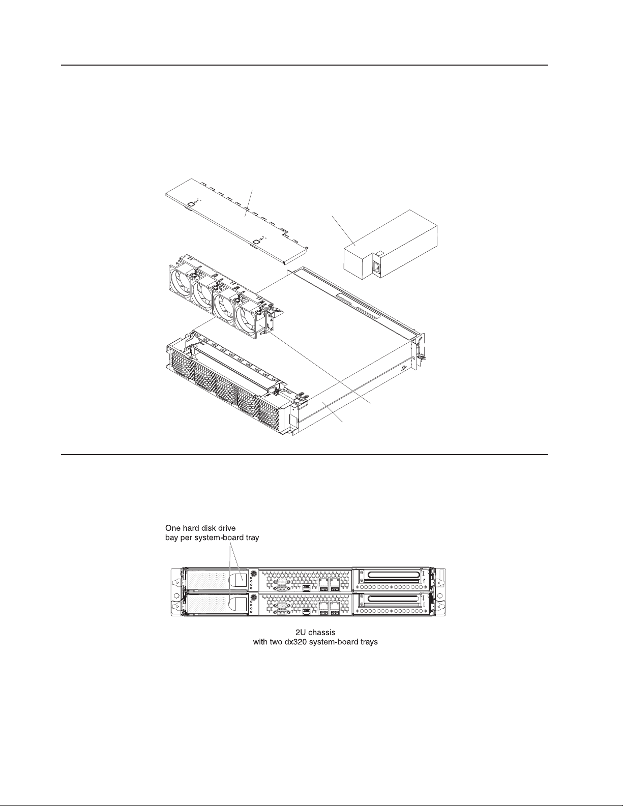
Flexible chassis features
The following illustration shows an IBM System x iDataPlex 2U flex chassis. The 2U
flex chassis contains a power supply and a fan assembly that provide operating
power and cooling for all components in the chassis. The 2U flex chassis can
support two dx320 system-board trays.
Note: The illustrations in this document might differ slightly from your hardware.
Fan assembly
cover
Power supply
2U compute server
The dx320 2U compute server solution consists of two identical system-board trays
installed in a 2U flex chassis. Each system-board tray has one 3.5–inch hard disk
drive bay and one PCIe slot.
Fan assembly
2U chassis
12 IBM iDataPlex dx320 User's Guide
Page 25

Operator panel controls, LEDs, connectors, and power
The following illustration shows the controls, LEDs, and connectors on the front of
the dx320 system-board tray. The operator panel on the system-board tray is the
same for all dx320 server configurations.
Power control
button
Power-on LED
Hard disk drive
activity LED
Locator LED
System error LED
Systems
management
Ethernet
link LED
Serial
Video
Systems
management
speed LED
Systems
management port
Ethernet link
activity/status
LED
Ethernet
connectors
Ethernet
connection
speed LED
USB connectors
Power-control button: Press this button to turn the system-board tray on and off
manually.
Serial connector: Connect a 9–pin serial device to this connector.
Systems management Ethernet link LED: This LED is on the Systems
Management Ethernet connector. When this LED is lit, it indicates that there is an
active link connection on the 10BASE-T or 100BASE-TX interface for the Ethernet
port.
Systems management Ethernet connection speed LED: This LED is on the
Systems Management Ethernet connector. When this LED is lit and is amber, it
indicates that the Ethernet network speed is 100 Mbps. When this LED is not lit, it
indicates that the Ethernet network speed is 10 Mbps.
Ethernet link activity/status LED: This LED is on each Ethernet connector. When
this LED is lit, it indicates that there is an active link connection on the 10BASE-T,
100BASE-TX, or 1000BASE-TX interface for the Ethernet port. When this LED is
flashing, it indicates that the server is transmitting to or receiving signals from the
Ethernet LAN that is connected to the Ethernet port.
Ethernet connection speed LED: This LED is on the each Ethernet connector.
When this LED is lit and is amber, it indicates that the Ethernet network speed is 1
Gbps. When this LED is lit and is green, it indicates that the Ethernet network
speed is 100 Mbps. When this LED is not lit, it indicates that the Ethernet network
speed is 10 Mbps.
USB connectors: Connect USB 2.0 devices to these connectors.
Ethernet connectors: Use these connectors to connect the server to a network.
Systems management port: Connect a systems management device to this
connector.
Video connector: Connect a monitor to this connector.
Chapter 2. Components, features, and controls 13
Page 26

Locator LED: This LED can be lit remotely by the system administrator to aid in
visually locating the server.
System-error LED: When this LED is lit, it indicates that a system error has
occurred. The source of the error is logged in the BMC system-event log that is
accessed in the BIOS Setup Utility program.
Hard disk drive activity LED: When this LED is flashing, it indicates that an
associated hard disk drive is in use.
Power-on LED: When this LED is lit, it indicates that the system-board tray is
turned on.
Note: If this LED is off, it does not mean that no electrical power is present. The
LED might be burned out. To remove all electrical power, you must disconnect the
power cord from the chassis.
Rear connectors
Power-cord connector: Connect the power cord to this connector. When the
chassis is installed in an iDataPlex rack, it is connected automatically to power
through a power cord that is mounted to the rack rail.
Turning on the system-board tray
After you install the system-board tray in a chassis, the system-board tray can start
in any of the following ways:
v You can press the power-control button on the front of the system-board tray
(see “Operator panel controls, LEDs, connectors, and power” on page 13) to start
the server.
v You can turn on the system-board tray remotely by using the management
appliance.
v If the system-board tray is connected to power, the operating system supports
the Wake on LAN feature, and the Wake on LAN feature has not been disabled,
the Wake on LAN feature can turn on the system-board tray.
v In an IPMI environment, the system administrator can turn on the system-board
tray using the BMC IPMI Chassis Control command.
v If a power failure occurs, the system-board tray can start automatically when
power is restored, if it is configured to do so.
14 IBM iDataPlex dx320 User's Guide
Page 27

Turning off the system-board tray
When you turn off the system-board tray, it is still connected to power through the
chassis power supply. The system-board tray still can respond to requests from the
service processor, such as a remote request to turn on the system-board tray. To
remove all power from the system-board tray, you must remove the tray from the
chassis.
Shut down the operating system before you turn off the system-board tray. See the
operating-system documentation for information about shutting down the operating
system.
The system-board tray can be turned off in any of the following ways:
v You can press the power-control button on the front of the system-board tray
(see “Operator panel controls, LEDs, connectors, and power” on page 13). This
starts an orderly shutdown of the operating system, if this feature is supported by
the operating system.
v You can turn off the system-board tray from the operating system, if the operating
system supports this feature. After an orderly shutdown of the operating system,
the system-board tray will be turned off automatically.
v In an IPMI environment, the system administrator can turn off the system-board
tray by using the BMC IPMI Chassis Control command.
v If the operating system stops functioning, you can press and hold the
power-control button for more than 4 seconds to turn off the system-board tray.
v You might be able to turn off the system-board tray by using an optional
management appliance.
– If the system is not operating correctly, the management appliance might
automatically turn off the system-board tray.
– Through the management appliance control interface, you might also be able
to configure the management appliance to turn off the system-board tray. For
additional information, see the documentation for your management appliance.
Chapter 2. Components, features, and controls 15
Page 28

16 IBM iDataPlex dx320 User's Guide
Page 29

Chapter 3. Installing optional devices
This section provides detailed instructions for installing optional hardware devices.
Installation guidelines
Before you install optional devices, read the following information:
v Read the safety information that begins on page v and “Handling static-sensitive
devices” on page 18. This information will help you work safely.
v Before you install optional hardware devices, make sure that the server is
working correctly. Start the server, and make sure that the operating system
starts, if an operating system is installed, or that a I9990305 error code is
displayed, indicating that an operating system was not found but the server is
otherwise working correctly. If the server is not working correctly, see the
Problem Determination and Service Guide for diagnostic information.
v Observe good housekeeping in the area where you are working. Place removed
covers and other parts in a safe place.
v Do not attempt to lift an object that you think is too heavy for you. If you have to
lift a heavy object, observe the following precautions:
– Make sure that you can stand safely without slipping.
– Distribute the weight of the object equally between your feet.
– Use a slow lifting force. Never move suddenly or twist when you lift a heavy
object.
– To avoid straining the muscles in your back, lift by standing or by pushing up
with your leg muscles.
v Back up all important data before you make changes to disk drives.
v Have a small flat-blade screwdriver and a small Phillips screwdriver available.
v You do not have to turn off the system-board tray to install or replace hot-plug
Universal Serial Bus (USB) devices. However, you must shut down the operating
system and turn off the system-board traybefore you install or remove
simple-swap drives.
v Blue on a component indicates touch points, where you can grip the component
to remove it from or install it in the server, open or close a latch, and so on.
v Orange on a component or an orange label on or near a component indicates
that the component can be hot-swapped, which means that if the server and
operating system support hot-swap capability, you can remove or install the
component while the server is running. (Orange can also indicate touch points on
hot-swap components.) See the instructions for removing or installing a specific
hot-swap component for any additional procedures that you might have to
perform before you remove or install the component.
© Copyright IBM Corp. 2011 17
Page 30

System reliability guidelines
To help ensure proper cooling and system reliability, make sure that the following
requirements are met:
v Each of the drive bays has a drive or a filler panel and electromagnetic
compatibility (EMC) shield installed in it.
v The system-board tray battery is operational. If the battery becomes defective,
replace it immediately.
v You have replaced one or both system-board trays within 2 minutes of removal.
v The upper system-board tray is not operating with the bottom system-board tray
removed or powered off.
v The system-board tray cover is installed and closed.
Handling static-sensitive devices
Attention: Static electricity can damage the server and other electronic devices.
To avoid damage, keep static-sensitive devices in their static-protective packages
until you are ready to install them.
To reduce the possibility of damage from electrostatic discharge, observe the
following precautions:
v Limit your movement. Movement can cause static electricity to build up around
you.
v The use of a grounding system is recommended. For example, wear an
electrostatic-discharge wrist strap, if one is available.
v Handle the device carefully, holding it by its edges or its frame.
v Do not touch solder joints, pins, or exposed circuitry.
v Do not leave the device where others can handle and damage it.
v While the device is still in its static-protective package, touch it to an unpainted
metal surface on the outside of the chassis or rack for at least 2 seconds. This
drains static electricity from the package and from your body.
v Remove the device from its package and install it directly into the system-board
tray without setting down the device. If it is necessary to set down the device, put
it back into its static-protective package. Do not place the device on a metal
surface.
v Take additional care when you handle devices during cold weather. Heating
reduces indoor humidity and increases static electricity.
18 IBM iDataPlex dx320 User's Guide
Page 31

Removing a system-board tray from a 2U chassis
Attention: When two system-board trays are installed in the chassis, do not
operate the upper system-board tray with the bottom system-board tray removed or
powered off, except for servicing. When the bottom system-board tray is removed
or powered-off, chassis-level system management information is not read correctly.
For example, chassis fan speeds and temperatures might be returned as zero
values. In this situation, the unit will continue to operate normally, since the power
supply and fans are designed to operate independently.
Note: If two system-board trays are installed in the chassis, they can be removed
independently of each other.
To remove a system-board tray from the chassis, complete the following steps.
1. Read the safety information that begins on page v and “Installation guidelines”
on page 17.
2. Turn off the system-board tray and all attached devices (see “Turning off the
system-board tray” on page 15).
3. If external cables are connected to the front of the system-board tray, note
where they are connected; then, remove them.
4. Press in on the two release handles, pull the system-board tray out of the
chassis, and set it on a flat, static-protective surface.
Chapter 3. Installing optional devices 19
Page 32

Removing the system-board tray cover
System-board
tray cover
System-board
tray
Release
latch
To remove the system-board tray cover, complete the following steps:
1. Read the safety information that begins on page v and “Installation guidelines”
on page 17.
2. Turn off the system-board tray and all attached devices (see “Turning off the
system-board tray” on page 15).
3. If the system-board tray is installed in a chassis, remove it (see “Removing a
system-board tray from a 2U chassis” on page 19).
4. Carefully set the system-board tray on a flat, static-protective surface, with the
cover side up.
5. Pull the cover release latch on each side of the system-board tray upward; then,
lift the cover open.
6. Lift the cover off the system-board tray and store it for future use.
Note: If two system-board trays are installed in a 2U chassis, both must have their
covers installed.
20 IBM iDataPlex dx320 User's Guide
Page 33

Removing a 3.5-inch simple-swap hard disk drive
To remove a simple-swap hard disk drive, complete the following steps:
1. Read the safety information that begins on page v and “Installation guidelines”
on page 17.
2. Turn off the system-board tray and all attached devices (see “Turning off the
system-board tray” on page 15).
3. Remove the filler panel from the simple-swap hard disk drive bay.
4. Pull the loops of the drive toward each other; then, pull the drive out of the drive
bay.
Note: A hard disk drive or filler panel must always be installed in each drive
bay when the server is turned on. Simple-swap disk drives must always have a
filler panel installed along with the hard disk drive.
5. Store the drive and filler panel for later use.
Chapter 3. Installing optional devices 21
Page 34

Installing a 3.5-inch simple-swap hard disk drive
To install a 3.5-inch simple-swap hard disk drive, complete the following steps:
1. Read the safety information that begins on page v and “Installation guidelines”
on page 17.
2. Turn off the system-board tray and all attached devices (see “Turning off the
system-board tray” on page 15).
3. Remove the filler panel from the simple-swap hard disk drive bay.
4. Touch the static-protective package that contains the hard disk drive to any
unpainted metal surface on the outside of the system-board tray for at least 2
seconds; then, remove the hard disk drive from the package.
Attention: Do not press on the top of the drive. Pressing the top might
damage the drive.
5. Align the drive with the guide rails in the drive bay.
6. Pull the loops of the drive toward each other; then, carefully slide the drive into
the bay until it stops, and release the loops.
Note: Do not release the loops on the drive until it is completely seated.
7. Install the filler panel in the simple-swap hard disk drive bay.
If you have other devices to install, do so now. Otherwise, turn on the system-board
tray (see “Turning on the system-board tray” on page 14).
22 IBM iDataPlex dx320 User's Guide
Page 35

Installing a memory module
When you install memory, you must install a pair of matched DIMMs. Each DIMM in
a pair must be the same size, speed, type, and technology to ensure that the server
will operate correctly. Make sure that the replacement DIMM is the correct type of
memory (see the Problem Determination and Service Guide for a list of memory
that is compatible with the server).
Note: The default memory operating speed is 533 MHz for Web 2.0 power saving
optimization. Memory operating speed can be adjusted using the Chipset option in
the BIOS Setup Utility program.
When you install DIMMs, you must install the DIMMs in the order shown in the
following tables, to maintain performance.
Table 3. DIMM installation sequence, non-interleaved
DIMM DIMM connectors
1st 1
2nd 3
3rd 5
Table 4. DIMM installation sequence, interleaved
DIMM pair DIMM connectors
1st 1 and 2
2nd 3 and 4
3rd 5 and 6
Chapter 3. Installing optional devices 23
Page 36

The following illustration shows the location of the DIMM slots on the dx320 system
board.
Microprocessor 2
connector
SATA 0
SATA 1
SATA 2
Microprocessor 1
connector
DIMM 1
DIMM 2
DIMM 3
DIMM 4
DIMM 5
DIMM 6
SATA 3
SATA 4
Battery
connector
To install a DIMM in the system-board tray, complete the following steps.
1. Read the documentation that comes with the DIMM.
2. Locate the DIMM connectors on the system board (see “System-board
connectors” on page 10). Determine the connectors into which you will install
the DIMMs.
24 IBM iDataPlex dx320 User's Guide
Page 37

3. Touch the static-protective package that contains the DIMM to any unpainted
metal surface on the outside of the system-board tray; then, remove the DIMM
from the package.
Attention: To avoid breaking the DIMM retaining clips or damaging the DIMM
connectors, open and close the clips gently.
4. Make sure that both of the connector retaining clips are in the fully open
position.
5. Orient the DIMM so that the DIMM keys align correctly with the connector on
the system board.
6. Insert the DIMM by applying pressure along the top of the DIMM at both ends
simultaneously. Make sure that the retaining clips snap into the closed positions.
Attention: If there is a gap between the DIMM and the retaining clips, the
DIMM has not been correctly installed. In this case, open the retaining clips and
remove the DIMM; then, reinsert the DIMM.
If you have other devices to install or remove, do so now. Otherwise, go to
“Completing the installation” on page 26.
Chapter 3. Installing optional devices 25
Page 38
Completing the installation
To complete the installation, complete the following tasks. Instructions for each task
are in one of the following sections.
1. Install the system-board tray cover (see “Reinstalling the system-board tray
cover”).
2. Install the system-board tray in the chassis (see “Reinstalling a system-board
tray in a 2U chassis” on page 27).
3. Connect the cables. For more information, see “Connecting the cables” on page
28.
4. For some devices, run the server BIOS Setup Utility program. For more
information, see “Updating the server configuration” on page 28.
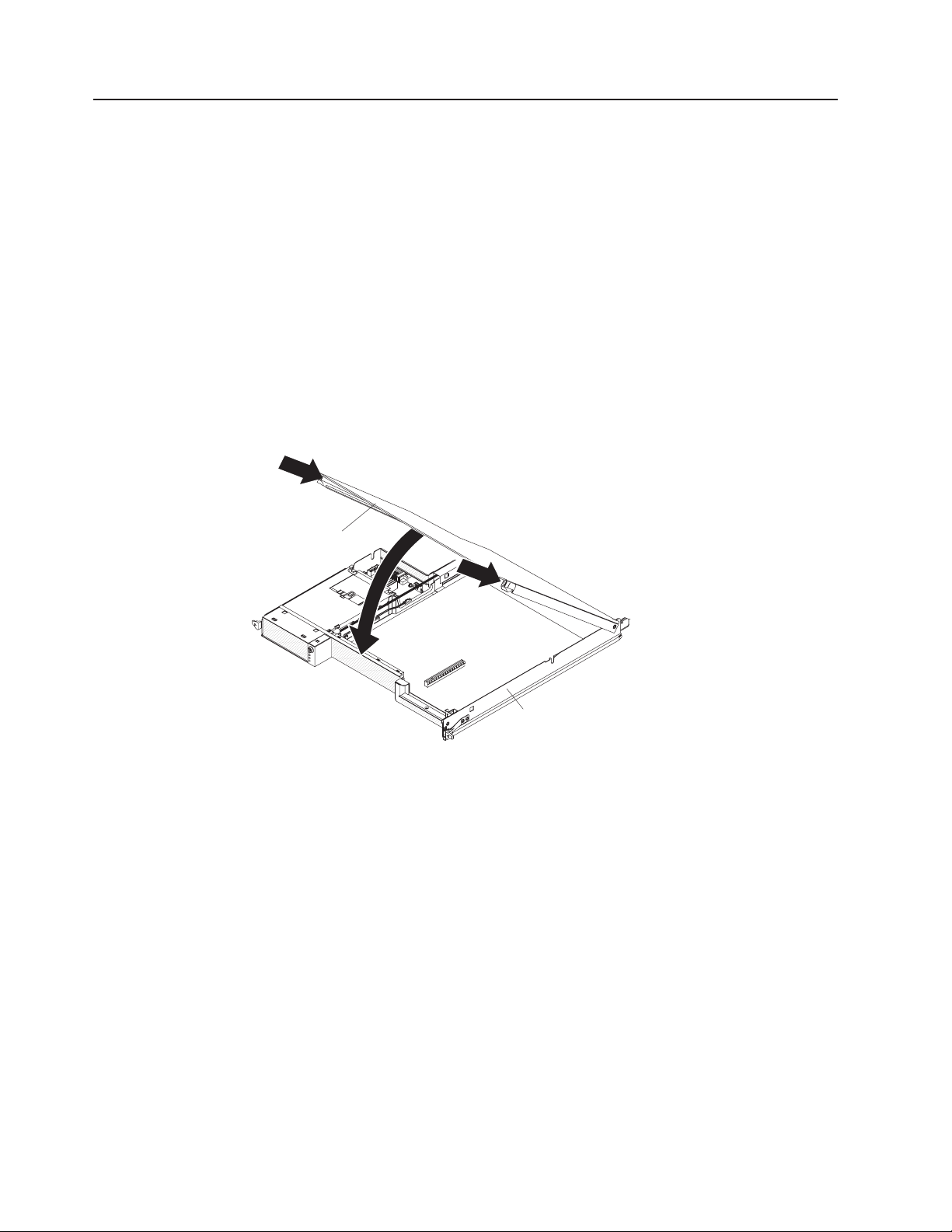
Reinstalling the system-board tray cover
Attention: You cannot install the system-board tray into the chassis until the
cover is installed and closed. Do not attempt to override this protection.
System-board
tray cover
System-board
tray
To reinstall the system-board tray cover, complete the following steps:
1. Lower the cover so that the pins at the rear slide down into the slots at the rear
of the system-board tray. Before you close the cover, make sure that all
components are installed and seated correctly, all internal cables are correctly
routed, and you have not left loose tools or parts inside the system-board tray.
2. Pivot the cover to the closed position until it clicks into place.
3. Install the system-board tray in the chassis (see “Reinstalling a system-board
tray in a 2U chassis” on page 27).
26 IBM iDataPlex dx320 User's Guide
Page 39

Reinstalling a system-board tray in a 2U chassis
To reinstall a system-board tray in a 2U chassis, complete the following steps:
1. Slide the system-board tray into the chassis until it stops and the release
handles click into place.
2. Reconnect the cables on the front of the system-board tray.
3. Turn on the system-board tray (see “Turning on the system-board tray” on page
14).
4. Make sure that the power-on LED on the system-board-tray operator panel is lit
continuously, indicating that the system-board tray is receiving power and is
turned on.
If you have changed the configuration of the system-board tray, you might have to
update the server configuration through the BIOS Setup Utility program. See
“Updating the server configuration” on page 28 for additional information.
Chapter 3. Installing optional devices 27
Page 40

Connecting the cables
Attention: To prevent damage to equipment, connect cables before you turn on
the system-board tray.
All cable connections, other than power, are on the front of the server. See
“Operator panel controls, LEDs, connectors, and power” on page 13 for connector
locations.
Updating the server configuration
When you start the server for the first time after you add or remove a device, you
might receive a message that the configuration has changed. The BIOS Setup
Utility program starts automatically so that you can save the new configuration
settings. For more information, see Chapter 4, “Configuring the dx320 server,” on
page 29.
Some optional devices have device drivers that you must install. For information
about installing device drivers, see the documentation that comes with each device.
For information about configuring the integrated Gigabit Ethernet controller, see
“Configuring the Gigabit Ethernet controller” on page 35.
28 IBM iDataPlex dx320 User's Guide
Page 41

Chapter 4. Configuring the dx320 server
To update the firmware, you might have to use an external USB CD-RW/DVD drive.
To run the BIOS Setup Utility or the Dynamic System Analysis (DSA) Preboot
diagnostic programs, you must have the following additional hardware:
v Monitor
v Combination USB keyboard and pointing device such as IBM part number
40K5372
v External USB CD-RW/DVD drive such as the IBM and Lenovo part number
73P4515 or 73P4516
The following configuration programs come with the dx320 server:
v BIOS Setup Utility program
The BIOS Setup Utility program is part of the basic input/output system (BIOS).
Use it to configure serial port assignments, change interrupt request (IRQ)
settings, change the startup-device sequence, set the date and time, and set
passwords. For information about using this program, see “Using the BIOS Setup
Utility program” on page 30.
v Baseboard management controller utility programs
Use these programs to configure the baseboard management controller, to
update the firmware and sensor data record/field replaceable unit (SDR/FRU)
data, and to remotely manage a network. For information about using these
programs, see “Using the baseboard management controller utility programs” on
page 33.
v Gigabit Ethernet controller configuration
To configure the integrated Gigabit Ethernet controller, see “Configuring the
Gigabit Ethernet controller” on page 35.
v IBM Dynamic System Analysis (DSA) Preboot Diagnostic Programs
The IBM Dynamic System Analysis (DSA) Preboot diagnostic programs are the
primary method of testing the major components of an IBM System x iDataPlex
server. You can use the USB memory key that comes with the iDataPlex rack
when you run the DSA Preboot diagnostic programs on an iDataPlex server.
To download the most current USB or ISO image of the DSA Preboot diagnostic
programs go to http://www.ibm.com/support/docview.wss?uid=psg1SERV-DSA.
For additional information about the DSA diagnostic programs, see the Problem
Determination and Service Guide for the iDataPlex server on the IBM
Documentation CD that comes with the iDataPlex rack solution.
© Copyright IBM Corp. 2011 29
Page 42

Using the BIOS Setup Utility program
Use the BIOS Setup Utility program to perform the following tasks:
v View configuration information
v View and change assignments for devices and I/O ports
v Set the date and time
v Set and change passwords
v Set and change the startup characteristics of the server and the order of startup
devices (startup-drive sequence)
v Set and change settings for advanced hardware features
v View and clear the error and event logs
v Resolve configuration conflicts
Starting the BIOS Setup Utility program
To start the BIOS Setup Utility program, complete the following steps:
1. Turn on the server.
2. When the prompt Press F1 for BIOS Setup appears, press F1. If you have set
both a user password and a supervisor password, you must type the supervisor
password to access the full BIOS Setup Utility menu. If you do not type the
supervisor password, a limited BIOS Setup Utility menu is available.
3. Select the settings to view or change.
BIOS Setup Utility menu choices
The following choices are on the BIOS Setup Utility main window taskbar.
Depending on the version of the BIOS code, some taskbar choices might differ
slightly from these descriptions.
v Main
Select this choice to view system information, such as the machine type and
model, serial number, Universally Unique Identifier (UUID), system board
identifier, asset tag number; information about the BIOS, microprocessors,
system memory size; and to view or change the system date and time. This is
the default page that is displayed when you start the BIOS Setup Utility program.
v Advanced
Select this choice to view or configure advanced features for the server hardware
and software.
– CPU configuration
Configure advanced features for the microprocessors.
– SATA configuration
View each recognized SATA device, and configure SATA as disabled,
enhanced, or compatible.
– Super I/O configuration
Select the base address for the serial port used by the Super I/O chipset.
– USB configuration
View the USB configuration and enable or disable USB functions and legacy
USB support.
– ACPI configuration
View and change the settings in the Advanced Configuration And Power
Interface (ACPI), such as whether to enable support for the advanced
programmable interrupt controller.
30 IBM iDataPlex dx320 User's Guide
Page 43

– APM configuration
View and change the settings in the advanced power management (APM)
configuration, such as whether the server should automatically restart when
ac power is restored.
– Event log configuration
View the event log, clear the event log, or enable or disable PCI Express
advanced error logging.
– IPMI configuration
View and change the settings in the Intelligent Platform Management Interface
(IPMI) configuration: view the version of IPMI and the version of BMC
firmware; view and change the addresses and subnet mask for the LAN
configuration; view or clear the BMC system event log; specify whether the
BMC resets the server or powers down the server in the event the operating
system crashes or fails to respond (enable or disable the BMC watchdog
timer action).
– Remote Access configuration
Configure the type of remote access and the parameters for remote access,
such as the serial port and mode used.
– Memory settings
View recognized DIMMs and enable a DIMM after it replaces a failed DIMM.
– NMI auto reboot
Configure whether the server automatically restarts when it receives a
non-maskable interrupt.
v PCIPnP
Select this choice to view or change advanced settings for the PCI bus and plug
and play (PnP) interface. You can change the master latency timer value, clear
non-volatile RAM, and specify whether BIOS or the operating system should
configure all the devices in the server.
v Boot
Select this choice to specify the server startup options, including the boot device
sequence, type, and priority.
v Security
Select this choice to specify the supervisor password and user (power-on)
password.
v Chipset
Select this choice to specify the advanced options for the memory controller
chipset, including default memory operating speed.
v Exit
Select this choice to save your changes and exit the BIOS Setup Utility program,
to discard your changes and exit, to discard your changes without exiting the
program, or to load the default values for all the setup options.
Chapter 4. Configuring the dx320 server 31
Page 44

Passwords
User password
From the Security choice, you can set, change, and delete a user (power-on)
password and a supervisor password.
If you set only a user password, you must type the user password to complete the
system startup.
A supervisor password is intended to be used by a system administrator; it limits
access to the configuration choices. If you set only a supervisor password, you do
not have to type a password to complete the system startup, but you must type the
supervisor password to access all the BIOS Setup Utility program configuration
choices.
If you set a user password for a user and a supervisor password for a system
administrator, you can type either password to complete the system startup. A
system administrator who types the supervisor password has access to the full
BIOS Setup Utility program configuration choices; the system administrator can give
the user authority to set, change, and delete the user password. A user who types
the user password has access to only the limited BIOS Setup Utility program
configuration choices; the user can set, change, and delete the user password, if
the system administrator has given the user that authority.
If a user password is set, when you turn on the server, the system startup will not
be completed until you type the user password. You can use any combination of up
to seven characters (A–Z, a–z, and 0–9) for the password.
If you forget the user password, you can regain access to the server in any of the
following ways:
v If a supervisor password is set, type the supervisor password at the password
prompt (see “Supervisor password”). Start the BIOS Setup Utility program and
reset the user password.
v Remove the battery from the server and then reinstall it. For instructions for
removing the battery, see the Problem Determination and Service Guide on the
IBM Documentation CD.
v Press the Clear CMOS button on the system board to clear the user and
supervisor passwords. See the Problem Determination and Service Guide on the
IBM Documentation CD for additional information.
Supervisor password
If a supervisor password is set, you must type the supervisor password for access
to the full BIOS Setup Utility settings. You can use any combination of up to seven
characters (A–Z, a–z, and 0–9) for the password.
If you forget the supervisor password, you can reset it after you press the Clear
CMOS button. See the Problem Determination and Service Guide on the IBM
Documentation CD for additional information.
32 IBM iDataPlex dx320 User's Guide
Page 45

Using the baseboard management controller utility programs
The baseboard management controller provides basic service-processor
environmental monitoring functions for the server. If an environmental condition
exceeds a threshold or if a system component fails, the baseboard management
controller lights LEDs to help you diagnose the problem and also records the error
in the BMC system event log.
Use the baseboard management controller utility programs to configure the
baseboard management controller, download firmware updates, and remotely
manage a network.
Note: You can update the baseboard management controller (BMC) firmware to the
latest version. See “Using the baseboard management controller firmware update
utility program” for the instructions to update the BMC firmware.
Using the baseboard management controller configuration utility program
Use the baseboard management controller configuration utility program to view or
change the baseboard management controller configuration settings. You can also
use the utility program to save the configuration to a file for use on multiple servers.
To download the program, complete the following steps.
Note: Changes are made periodically to the IBM Web site. The actual procedure
might vary slightly from what is described in this document.
1. Go to http://www.ibm.com/systems/support/.
2. Under Product support, click System x.
3. Under Popular links, click Software and device drivers.
4. Click System x iDataPlex dx320 server to display the matrix of downloadable
files for the system-board tray.
5. From the BMC software, copy the files bmc.exe and Init.ini to a setup utility
diskette.
Note: You must attach an optional monitor, USB keyboard, and USB diskette drive
to the server to run this program.
To start the baseboard management controller configuration utility program,
complete the following steps:
1. Connect a monitor, USB keyboard, and USB diskette drive to the connectors on
the front of the system-board tray.
2. Insert the configuration utility diskette into the diskette drive and restart the
server.
3. From a command-line prompt, type bmc_cfg and press Enter.
4. Follow the instructions on the screen.
Using the baseboard management controller firmware update utility program
Use the baseboard management controller firmware update utility program to
download a baseboard management controller firmware update. This program
updates the baseboard management controller firmware only and does not affect
any device drivers.
Chapter 4. Configuring the dx320 server 33
Page 46

Important: To ensure proper operation, be sure to update the baseboard
management controller firmware before you update the BIOS code.
To download the program, complete the following steps.
Note: Changes are made periodically to the IBM Web site. The actual procedure
might vary slightly from what is described in this document.
1. Go to http://www.ibm.com/systems/support/.
2. Under Product support, click System x.
3. Under Popular links, click Software and device drivers.
4. Click System x iDataPlex dx320 server to display the matrix of downloadable
files for the system-board tray.
5. From the BMC software, copy the files bmc.exe and Init.ini to a setup utility
diskette.
To update the firmware, use one of the following procedures:
v If the Linux or Windows operating-system update package is available from the
World Wide Web and you have obtained it, follow the instructions that come with
the package.
v If you are using a diskette, complete the following steps:
1. Connect a monitor, USB keyboard, and USB diskette drive to the connectors
on the front of the system-board tray.
2. Turn on the system-board tray.
3. Insert the firmware update diskette into the diskette drive.
4. From a command line, type flash -? and press Enter.
For the program to interface with the baseboard management controller, the
parameters in the Intf.ini file must be set correctly. To modify the Intf.ini file, use the
baseboard management controller setup utility program or a text editor.
Using the baseboard management controller management utility program
Use the baseboard management controller management utility program to remotely
manage and configure a server network. The following features are available from
the program:
v IPMI Shell
Use this feature to remotely perform power-management and system
identification control functions over a LAN or serial port interface from a
command-line interface. Use this feature also to remotely view the event log.
v Serial over LAN Proxy
Use this feature to remotely perform control and management functions over a
Serial over LAN network. Use this feature also to remotely view and change the
BIOS settings.
To download the utility program and create the baseboard management controller
management utility CD, complete the following steps.
Note: Changes are made periodically to the IBM Web site. The actual procedure
might vary slightly from what is described in this document.
1. Go to http://www.ibm.com/systems/support/.
2. Under Product support, click System x.
34 IBM iDataPlex dx320 User's Guide
Page 47

3. Under Popular links, click Software and device drivers.
4. Click System x iDataPlex dx320 server to display the matrix of downloadable
files for the system-board tray.
5. From the BMC software, use the information on the CD to install and use the
program.
Configuring the Gigabit Ethernet controller
The Ethernet controller is integrated on the system board. It provides an interface
for connecting to a 10 Mbps, 100 Mbps, or 1 Gbps network and provides full duplex
(FDX) capability, which enables simultaneous transmission and reception of data on
the network. If the Ethernet port in the server supports auto-negotiation, the
controller detects the data-transfer rate (10BASE-T, 100BASE-TX, or 1000BASE-T)
and duplex mode (full-duplex or half-duplex) of the network and automatically
operates at that rate and mode.
You do not have to set any jumpers or configure the controller. However, you must
install a device driver to enable the operating system to address the controller.
Notes:
1. Changes are made periodically to the IBM Web site. The actual procedure might
vary slightly from what is described in this document.
2. To install the device driver for the Ethernet controller, you might need to use an
external USB CD-RW/DVD drive such as the IBM and Lenovo part number
73P4515 or 73P4516.
To find the device driver or updated information about configuring the controller,
complete the following steps:
1. Go to http://www.ibm.com/systems/support/.
2. Under Product support, click System x.
3. Under Popular links, click Software and device drivers.
4. Click System x iDataPlex dx320 server to display the matrix of downloadable
files for the server.
Chapter 4. Configuring the dx320 server 35
Page 48

Firmware updates
The firmware for the server is periodically updated and is available for download on
the Web. Go to http://www.ibm.com/systems/support/ to check for the latest level of
firmware, such as BIOS code, vital product data (VPD) code, and device drivers.
Download the latest firmware for the server; then, install the firmware, using the
instructions that are included with the downloaded files.
When you replace a device in the server, you might have to either update the
server with the latest version of the firmware that is stored in memory on the device
or restore the pre-existing firmware.
The following firmware updates are downloadable from the Web at
http://www.ibm.com/systems/support/. Follow the instructions on how to apply the
updates using documentation that is included in the downloaded files:
v BIOS code
v BMC firmware
v FRU/SDR data
Major components contain VPD code. You can select to update the VPD code when
you update the BIOS code.
Note: Changes are made periodically to the IBM Web site. The actual procedure
might vary slightly from what is described in this document.
To download the firmware for the server:
1. Go to http://www.ibm.com/systems/support/.
2. Under Product support, click System x.
3. Under Popular links, click Software and device drivers.
4. Click System x iDataPlex dx320 server to display the matrix of downloadable
files for the server.
For additional information about tools for updating, managing, and deploying
firmware, see the System x and xSeries Tools Center at http://
publib.boulder.ibm.com/infocenter/toolsctr/v1r0/index.jsp.
36 IBM iDataPlex dx320 User's Guide
Page 49

Appendix A. Getting help and technical assistance
If you need help, service, or technical assistance or just want more information
about IBM products, you will find a wide variety of sources available from IBM to
assist you. This section contains information about where to go for additional
information about IBM and IBM products, what to do if you experience a problem
with your system, and whom to call for service, if it is necessary.
Before you call
Before you call, make sure that you have taken these steps to try to solve the
problem yourself:
v Check all cables to make sure that they are connected.
v Check the power switches to make sure that the system and any optional
devices are turned on.
v Use the troubleshooting information in your system documentation, and use the
diagnostic tools that come with your system. Information about diagnostic tools is
in the Problem Determination and Service Guide on the IBM Documentation CD
that comes with your system.
v Go to the IBM Support Web site at http://www.ibm.com/systems/support/ to check
for technical information, hints, tips, and new device drivers or to submit a
request for information.
You can solve many problems without outside assistance by following the
troubleshooting procedures that IBM provides in the online help or in the
documentation that is provided with your IBM product. The documentation that
comes with IBM systems also describes the diagnostic tests that you can perform.
Most systems, operating systems, and programs come with documentation that
contains troubleshooting procedures and explanations of error messages and error
codes. If you suspect a software problem, see the documentation for the operating
system or program.
Using the documentation
Information about your IBM system and preinstalled software, if any, or optional
device is available in the documentation that comes with the product. That
documentation can include printed documents, online documents, readme files, and
help files. See the troubleshooting information in your system documentation for
instructions for using the diagnostic programs. The troubleshooting information or
the diagnostic programs might tell you that you need additional or updated device
drivers or other software. IBM maintains pages on the World Wide Web where you
can get the latest technical information and download device drivers and updates.
To access these pages, go to http://www.ibm.com/systems/support/ and follow the
instructions. Also, some documents are available through the IBM Publications
Center at http://www.ibm.com/shop/publications/order/.
Getting help and information from the World Wide Web
On the World Wide Web, the IBM Web site has up-to-date information about IBM
systems, optional devices, services, and support. The address for IBM System x
and xSeries®information is http://www.ibm.com/systems/x/.
© Copyright IBM Corp. 2011 37
®
Page 50

The address for IBM iDataPlex information is http://www.ibm.com/systems/x/
hardware/idataplex/index.html. The address for IBM BladeCenter®information is
http://www.ibm.com/systems/bladecenter/.
You can find service information for IBM systems and optional devices at
http://www.ibm.com/systems/support/.
Software service and support
Through IBM Support Line, you can get telephone assistance, for a fee, with usage,
configuration, and software problems with System x and xSeries servers,
BladeCenter products, IntelliStation
about which products are supported by Support Line in your country or region, see
http://www.ibm.com/services/sl/products/.
For more information about Support Line and other IBM services, see
http://www.ibm.com/services/, or see http://www.ibm.com/planetwide/ for support
telephone numbers. In the U.S. and Canada, call 1-800-IBM-SERV
(1-800-426-7378).
Hardware service and support
You can receive hardware service through your IBM reseller or IBM Services. To
locate a reseller authorized by IBM to provide warranty service, go to
http://www.ibm.com/partnerworld/ and click Find a Business Partner on the right
side of the page. For IBM support telephone numbers, see http://www.ibm.com/
planetwide/. In the U.S. and Canada, call 1-800-IBM-SERV (1-800-426-7378).
®
workstations, and appliances. For information
In the U.S. and Canada, hardware service and support is available 24 hours a day,
7 days a week. In the U.K., these services are available Monday through Friday,
from 9 a.m. to 6 p.m.
IBM Taiwan product service
IBM Taiwan product service contact information:
IBM Taiwan Corporation
3F, No 7, Song Ren Rd.
Taipei, Taiwan
Telephone: 0800-016-888
38 IBM iDataPlex dx320 User's Guide
Page 51

Appendix B. Notices
This information was developed for products and services offered in the U.S.A.
IBM may not offer the products, services, or features discussed in this document in
other countries. Consult your local IBM representative for information on the
products and services currently available in your area. Any reference to an IBM
product, program, or service is not intended to state or imply that only that IBM
product, program, or service may be used. Any functionally equivalent product,
program, or service that does not infringe any IBM intellectual property right may be
used instead. However, it is the user's responsibility to evaluate and verify the
operation of any non-IBM product, program, or service.
IBM may have patents or pending patent applications covering subject matter
described in this document. The furnishing of this document does not give you any
license to these patents. You can send license inquiries, in writing, to:
IBM Director of Licensing
IBM Corporation
North Castle Drive
Armonk, NY 10504-1785
U.S.A.
INTERNATIONAL BUSINESS MACHINES CORPORATION PROVIDES THIS
PUBLICATION “AS IS” WITHOUT WARRANTY OF ANY KIND, EITHER EXPRESS
OR IMPLIED, INCLUDING, BUT NOT LIMITED TO, THE IMPLIED WARRANTIES
OF NON-INFRINGEMENT, MERCHANTABILITY OR FITNESS FOR A
PARTICULAR PURPOSE. Some states do not allow disclaimer of express or
implied warranties in certain transactions, therefore, this statement may not apply to
you.
Trademarks
This information could include technical inaccuracies or typographical errors.
Changes are periodically made to the information herein; these changes will be
incorporated in new editions of the publication. IBM may make improvements and/or
changes in the product(s) and/or the program(s) described in this publication at any
time without notice.
Any references in this information to non-IBM Web sites are provided for
convenience only and do not in any manner serve as an endorsement of those
Web sites. The materials at those Web sites are not part of the materials for this
IBM product, and use of those Web sites is at your own risk.
IBM may use or distribute any of the information you supply in any way it believes
appropriate without incurring any obligation to you.
IBM, the IBM logo, and ibm.com are trademarks or registered trademarks of
International Business Machines Corporation in the United States, other countries,
or both. If these and other IBM trademarked terms are marked on their first
occurrence in this information with a trademark symbol (
indicate U.S. registered or common law trademarks owned by IBM at the time this
information was published. Such trademarks may also be registered or common law
trademarks in other countries. A current list of IBM trademarks is available on the
Web at “Copyright and trademark information” at http://www.ibm.com/legal/
copytrade.shtml.
®or™
), these symbols
© Copyright IBM Corp. 2011 39
Page 52

Adobe and PostScript are either registered trademarks or trademarks of Adobe
Systems Incorporated in the United States and/or other countries.
Cell Broadband Engine is a trademark of Sony Computer Entertainment, Inc., in the
United States, other countries, or both and is used under license therefrom.
Intel, Intel Xeon, Itanium, and Pentium are trademarks or registered trademarks of
Intel Corporation or its subsidiaries in the United States and other countries.
Java and all Java-based trademarks are trademarks of Sun Microsystems, Inc., in
the United States, other countries, or both.
Linux is a registered trademark of Linus Torvalds in the United States, other
countries, or both.
Microsoft, Windows, and Windows NT are trademarks of Microsoft Corporation in
the United States, other countries, or both.
UNIX is a registered trademark of The Open Group in the United States and other
countries.
Other company, product, or service names may be trademarks or service marks of
others.
Important notes
This product is not intended to be connected directly or indirectly by any means
whatsoever to interfaces of public telecommunications networks nor is it intended to
be used in a public services network.
Processor speed indicates the internal clock speed of the microprocessor; other
factors also affect application performance.
CD or DVD drive speed is the variable read rate. Actual speeds vary and are often
less than the possible maximum.
When referring to processor storage, real and virtual storage, or channel volume,
KB stands for 1024 bytes, MB stands for 1 048 576 bytes, and GB stands for
1 073 741 824 bytes.
When referring to hard disk drive capacity or communications volume, MB stands
for 1 000 000 bytes, and GB stands for 1 000 000 000 bytes. Total user-accessible
capacity can vary depending on operating environments.
Maximum internal hard disk drive capacities assume the replacement of any
standard hard disk drives and population of all hard disk drive bays with the largest
currently supported drives that are available from IBM.
Maximum memory might require replacement of the standard memory with an
optional memory module.
IBM makes no representation or warranties regarding non-IBM products and
services that are ServerProven
of merchantability and fitness for a particular purpose. These products are offered
and warranted solely by third parties.
40 IBM iDataPlex dx320 User's Guide
®
, including but not limited to the implied warranties
Page 53

IBM makes no representations or warranties with respect to non-IBM products.
Support (if any) for the non-IBM products is provided by the third party, not IBM.
Some software might differ from its retail version (if available) and might not include
user manuals or all program functionality.
German Ordinance for Work gloss statement
The product is not suitable for use with visual display work place devices according
to clause 2 of the German Ordinance for Work with Visual Display Units.
Das Produkt ist nicht für den Einsatz an Bildschirmarbeitsplätzen im Sinne§2der
Bildschirmarbeitsverordnung geeignet.
Electronic emission notices
When you attach a monitor to the equipment, you must use the designated monitor
cable and any interference suppression devices that are supplied with the monitor.
Federal Communications Commission (FCC) statement
Note: This equipment has been tested and found to comply with the limits for a
Class A digital device, pursuant to Part 15 of the FCC Rules. These limits are
designed to provide reasonable protection against harmful interference when the
equipment is operated in a commercial environment. This equipment generates,
uses, and can radiate radio frequency energy and, if not installed and used in
accordance with the instruction manual, may cause harmful interference to radio
communications. Operation of this equipment in a residential area is likely to cause
harmful interference, in which case the user will be required to correct the
interference at his own expense.
Properly shielded and grounded cables and connectors must be used in order to
meet FCC emission limits. IBM is not responsible for any radio or television
interference caused by using other than recommended cables and connectors or by
unauthorized changes or modifications to this equipment. Unauthorized changes or
modifications could void the user's authority to operate the equipment.
This device complies with Part 15 of the FCC Rules. Operation is subject to the
following two conditions: (1) this device may not cause harmful interference, and (2)
this device must accept any interference received, including interference that may
cause undesired operation.
Industry Canada Class A emission compliance statement
This Class A digital apparatus complies with Canadian ICES-003.
Avis de conformité à la réglementation d'Industrie Canada
Cet appareil numérique de la classe A est conforme à la norme NMB-003 du
Canada.
Australia and New Zealand Class A statement
Attention: This is a Class A product. In a domestic environment this product may
cause radio interference in which case the user may be required to take adequate
measures.
Appendix B. Notices 41
Page 54

United Kingdom telecommunications safety requirement
Notice to Customers
This apparatus is approved under approval number NS/G/1234/J/100003 for indirect
connection to public telecommunication systems in the United Kingdom.
European Union EMC Directive conformance statement
This product is in conformity with the protection requirements of EU Council
Directive 2004/108/EC on the approximation of the laws of the Member States
relating to electromagnetic compatibility. IBM cannot accept responsibility for any
failure to satisfy the protection requirements resulting from a nonrecommended
modification of the product, including the fitting of non-IBM option cards.
This product has been tested and found to comply with the limits for Class A
Information Technology Equipment according to CISPR 22/European Standard EN
55022. The limits for Class A equipment were derived for commercial and industrial
environments to provide reasonable protection against interference with licensed
communication equipment.
Attention: This is a Class A product. In a domestic environment this product may
cause radio interference in which case the user may be required to take adequate
measures.
European Community contact:
IBM Technical Regulations
Pascalstr. 100, Stuttgart, Germany 70569
Telephone: 0049 (0)711 785 1176
Fax: 0049 (0)711 785 1283
E-mail: tjahn@de.ibm.com
Taiwanese Class A warning statement
42 IBM iDataPlex dx320 User's Guide
Page 55

Chinese Class A warning statement
Japanese Voluntary Control Council for Interference (VCCI) statement
Korean Class A warning statement
Appendix B. Notices 43
Page 56

44 IBM iDataPlex dx320 User's Guide
Page 57

Index
A
administrator password
See supervisor password
assistance, getting 37
attention notices 4
availability 7
B
baseboard management controller (BMC) 6
baseboard management controller utility programs 33
BIOS Setup Utility program 30
button, clear CMOS (password override) 32
bypassing an unknown password 32
C
caution statements 4
Class A electronic emission notice 41
configuration
BIOS Setup Utility 30
configuration programs 29
Gigabit Ethernet controller 29
configuring
the Ethernet controller 35
connectors 13, 14
controller
BMC 6
Ethernet 35
controls 13
D
danger statements 4
device drivers 8
dimensions 5
DIMM
installing 23
DIMMs
branch 24
channel 24
documentation CD 3
F
FCC Class A notice 41
features 5
BMC 6
firmware, updating 33, 36
forgotten password, bypassing 32
G
getting help 37
gloss statement (Germany) 41
H
hard disk drive
activity LED 14
installing
3.5-inch simple-swap 22
removing
3.5-inch simple-swap 21
specifications 5
hardware service and support 38
help, getting 37
humidity 5
I
IBM Support Line 38
important notices 4
installing
hard disk drive
3.5-inch simple-swap 22
memory module 23
system-board tray cover 26
integrated functions 5
L
LEDs 13
link LED 13
Locator (location) LED 14
E
electrical input 5
electronic emission Class A notice 41
environment 5
Ethernet
integrated on system board 35
Ethernet connector 13
Ethernet controller
configuring 35
Ethernet controller configuration 29
Ethernet transmit/receive activity LED 13
© Copyright IBM Corp. 2011 45
memory 5
memory module
branch 24
channel 24
installing 23
microprocessor 5, 6
N
notes 4
notes, important 40
notices 39
M
Page 58

notices (continued)
electronic emission 41
FCC, Class A 41
notices and statements 4
P
password i
clear CMOS button 32
override 32
supervisor 32
user 32
power LED 14
power requirement 5
power-control button 13
power-cord connector 14
power-on password
See user password
publications 2
R
RAS features 7
reinstalling
system-board tray 27
reliability 7
removing
hard disk drive
3.5-inch simple-swap 21
system-board tray cover 20
S
serial connector 13
serial number, location 1
serviceability 7
size 5
SMP 6
software service and support 38
specifications 5
starting the system-board tray 14
statements and notices 4
stopping the system-board tray 15
supervisor password 32
support, web site 37
symmetric multiprocessing 6
system board
components 9
connectors 10
jumpers 11
system-board tray
reinstalling 27
system-board tray cover
installing 26
removing 20
system-error LED 14
systems management 7
T
telephone numbers 38
temperature 5
trademarks 39
turning off the system-board tray 15
turning on the system-board tray 14
TÜV gloss statement 41
U
United States electronic emission Class A notice 41
United States FCC Class A notice 41
unknown password, bypassing 32
UpdateXpress 8
updating firmware 36
updating the firmware 33
USB connector 13
user password 32
using
baseboard management controller utility
programs 33
utility program
BIOS Setup 30
V
video connector 13
W
web site
publication ordering 37
support 37
support line, telephone numbers 38
weight 5
46 IBM iDataPlex dx320 User's Guide
Page 59

Page 60

Part Number: 90Y5674
Printed in USA
(1P) P/N: 90Y5674
 Loading...