

IBM Deskstar 120 GXP, IC35L060AVVA07, IC35L020AVVN07, IC35L040AVVN07, IC35L080AVVA07 Specifications
...Page 1

IBM storage products - official published specifications
Hard disk drive specifications
Deskstar 120 GXP
3.5 inch Ultra ATA/100 hard disk drive
IBM
Models:
Revision 4.1 18 June 2002
IC35L020AVVN07
IC35L040AVVN07
IC35L060AVVA07
IC35L080AVVA07
IC35L100AVVA07
IC35L120AVVA07
S07N-4778-08 Publication #2820
Page 2

This page intentionally left blank.
Page 3
IBM storage products - official published specifications
Hard disk drive specifications
Deskstar 120 GXP
3.5 inch Ultra ATA/100 hard disk drive
IBM
Models:
Revision 4.1 18 June 2002
IC35L020AVVN07
IC35L040AVVN07
IC35L060AVVA07
IC35L080AVVA07
IC35L100AVVA07
IC35L120AVVA07
S07N-4778-08 Publication #2820
Page 4

1st Edition (Revision 0.1) S07N-4778-00 (1 October 2001) Preliminary
2nd Edition (Revision 0.2) S07N-4778-01 (24 October 2001) Preliminary
3rd Edition (Revision 0.3) S07N-4778-02 (7 November 2001) Preliminary
4th Edition (Revision 1.0) S07N-4778-03 (9 November 2001)
5th Edition (Revision 2.0) S07N-4778-04 (10 December 2001)
6th Edition (Revision 2.1) S07N-4778-05 (10 January 2002 )
7th Edition (Revision 3.0) S07N-4778-06 (18 February 2002)
8th Edition (Revision 4.0) S07N-4778-07 (11 April 2002 )
9th Edition (Revision 4.1) S07N-4778-08 (18 June 2002 )
The following paragraph does not apply to the United Kingdom or any country where such provisions are
inconsistent with local law: INTERNATIONAL BUSINESS MACHINES CORPORATION PROVIDES THIS
PUBLICATION “AS IS” WITHOUT WARRANTY OF ANY KIND, EITHER EXPRESS OR IMPLIED, IN CLUDING, BUT NOT LIMITED TO, THE IMPLIED WARRANTIES OF MERCHANTABILITY OR FITNESS
FOR A PARTICULAR PURPOSE. Some states do not allow disclaimer or express or implied warranties in certain
transactions, therefore, this statement may not apply to you.
This publication could include technical inaccuracies or typographical errors. Changes are periodically made to the
information herein; these changes will be incorporated in new editions of the publication. IBM may make improvements or changes in any products or programs described in this publication at any time.
It is possible that this publication may contain reference to, or information about, IBM products (machines and
programs), programming, or services that are not announced in your country. Such references or information must
not be construed to mean that IBM intends to announce such IBM products, programming, or services in your
country.
Technical information about this product is available by contacting your local IBM representative or on the
|Internet at http://www.ibm.com/harddrive
IBM may have patents or pending patent applications covering subject matter in this document. The furnishing of
this document does not give you any license to these patents. You can send license inquiries in writing to the IBM
Director of Commercial Relations, IBM Corporation, Armonk, NY 10577.
©Copyright International Business Machines Corporation 2002. All rights reserved.
Note to U.S. Government Users —Documentation related to restricted rights —Use, duplication or disclosure is
subject to restrictions set forth in GSA ADP Schedule Contract with IBM Corp.
Page 5

Table of contents
iiiList of figures .....................................................................
11.0 General .......................................................................
11.1 Glossary ........................................................................
11.2 General caution .................................................................
11.3 References .....................................................................
32.0 General features ...............................................................
Part 1. Functional specification
...............................................
5
73.0 Fixed disk subsystem description ..............................................
73.1 Control Electronics ...............................................................
73.2 Head disk assembly .............................................................
73.3 Actuator ........................................................................
94.0 Drive characteristics ...........................................................
94.1 Default logical drive parameters ...................................................
104.2 Data sheet ....................................................................
114.3 Drive organization .............................................................
114.3.1 Drive format .............................................................
114.3.2 Cylinder allocation ........................................................
134.4 Performance characteristics ....................................................
134.4.1 Command overhead ......................................................
134.4.2 Mechanical positioning ....................................................
154.4.3 Drive ready time .........................................................
164.4.4 Data transfer speed ......................................................
174.4.5 Throughput ..............................................................
184.4.6 Operating modes .........................................................
195.0 Defect flagging strategy ......................................................
216.0 Specification ................................................................
216.1 Electrical interface ............................................................
216.1.1 Connector location .......................................................
226.1.2 Signal definition ..........................................................
256.1.3 Interface logic signal levels ................................................
266.2 Signal timings .................................................................
266.2.1 Reset timings ............................................................
276.2.2 PIO timings ..............................................................
296.2.3 Multiword DMA timings ....................................................
306.2.4 Ultra DMA timings ........................................................
386.2.5 Addressing of registers ....................................................
386.2.6 Cabling .................................................................
396.3 Jumper settings ...............................................................
396.3.1 Jumper pin location .......................................................
396.3.2 Jumper pin identification ..................................................
406.3.3 Jumper pin assignment ...................................................
416.3.4 Jumper positions .........................................................
456.4 Environment ..................................................................
456.4.1 Temperature and humidity .................................................
466.4.2 Corrosion test ............................................................
Deskstar 120GXP hard disk drive specifications
iii
Page 6

476.5 DC power requirements ........................................................
476.5.1 Input voltage .............................................................
476.5.2 Power supply current (typical) .............................................
496.5.3 Power supply generated ripple at drive power connector ......................
506.6 Reliability .....................................................................
506.6.1 Data integrity ............................................................
506.6.2 Cable noise interference ..................................................
506.6.3 Start/stop cycles .........................................................
506.6.4 Preventive maintenance ...................................................
506.6.5 Data reliability ............................................................
506.6.6 Required Power-Off Sequence .............................................
516.7 Mechanical specifications .......................................................
516.7.1 Physical dimensions ......................................................
536.7.2 Hole locations ............................................................
546.7.3 Connector locations ......................................................
546.7.4 Drive mounting ...........................................................
546.7.5 Heads unload and actuator lock ............................................
556.8 Vibration and shock ............................................................
556.8.1 Operating vibration .......................................................
556.8.2 Nonoperating vibration ....................................................
566.8.3 Operating shock .........................................................
566.8.4 Nonoperating shock ......................................................
576.8.5 Rotational shock .........................................................
586.9 Acoustics .....................................................................
596.10 Identification labels ...........................................................
606.11 Safety .......................................................................
606.11.1 UL and CSA standard conformity ..........................................
606.11.2 German Safety Mark ....................................................
606.11.3 Flammability ............................................................
606.11.4 Safe handling ...........................................................
606.11.5 Environment ............................................................
606.11.6 Secondary circuit protection ..............................................
616.12 Electromagnetic compatibility ..................................................
616.12.1 CE Mark ...............................................................
616.12.2 C-Tick Mark ............................................................
Part 2. Interface specification
...............................................
Deskstar 120GXP hard disk drive specifications
iv
63
657.0 General .....................................................................
657.1 Terminology ..................................................................
657.2 Deviations from standard .......................................................
678.0 Registers ....................................................................
688.1 Alternate Status Register .......................................................
688.2 Command Register ............................................................
688.3 Cylinder High Register .........................................................
688.4 Cylinder Low Register .........................................................
698.5 Data Register .................................................................
698.6 Device Control Register ........................................................
698.7 Drive Address Register ........................................................
708.8 Device/Head Register .........................................................
708.9 Error Register ................................................................
718.10 Features Register ............................................................
Page 7

Deskstar 120GXP hard disk drive specifications
v
718.11 Sector Count Register .........................................................
718.12 Sector Number Register .......................................................
728.13 Status Register ...............................................................
739.0 General operation ............................................................
739.1 Reset response ...............................................................
749.2 Register initialization ...........................................................
759.3 Diagnostic and reset considerations ..............................................
769.4 Sector Addressing Mode .......................................................
769.4.1 Logical CHS Addressing Mode .............................................
769.4.2 LBA Addressing Mode ....................................................
779.5 Overlapped and queued feature .................................................
789.6 Power management feature .....................................................
789.6.1 Power modes ............................................................
789.6.2 Power management commands ............................................
789.6.3 Standby timer ............................................................
799.6.4 Interface capability for power modes ........................................
809.7 S.M.A.R.T. function ............................................................
809.7.1 Attributes ................................................................
809.7.2 Attribute values ..........................................................
809.7.3 Attribute thresholds .......................................................
809.7.4 Threshold Exceeded Condition .............................................
809.7.5 S.M.A.R.T. commands ....................................................
809.7.6 Off-line read scanning ....................................................
809.7.7 Error log ................................................................
819.7.8 Self-test .................................................................
829.8 Security Mode Feature Set ......................................................
829.8.1 Security mode ...........................................................
829.8.2 Security level ............................................................
829.8.3 Passwords ..............................................................
839.8.4 Operation example .......................................................
869.8.5 Command table ..........................................................
889.9 Host Protected Area Function ...................................................
889.9.1 Example for operation (in LBA mode) .......................................
899.9.2 Security extensions .......................................................
909.10 Seek Overlap ................................................................
919.11 Write cache function ..........................................................
919.12 Reassign function ............................................................
919.13 Auto Reassign function ........................................................
919.13.1 Nonrecovered write errors ................................................
919.13.2 Nonrecovered read errors ................................................
929.13.3 Recovered read errors ...................................................
929.14 Power-Up In Standby feature set ...............................................
929.15 Advanced Power Management feature set (APM) ................................
939.16 Automatic Acoustic Management feature set (AAM) ..............................
939.17 Address Offset Feature .......................................................
939.17.1 Enable/Disable Address Offset Mode ......................................
949.17.2 Identify Device Data .....................................................
949.17.3 Exceptions in Address Offset Mode .......................................
9510.0 Command Protocol .........................................................
9610.1 PIO Data In commands .......................................................
9810.2 PIO Data Out commands ......................................................
10010.3 Non-data commands .........................................................
10110.4 DMA commands ............................................................
10210.5 DMA queued commands .....................................................
Page 8

Deskstar 120GXP hard disk drive specifications
vi
10311.0 Command descriptions ....................................................
10711.1 Check Power Mode (E5h/98h) ................................................
10811.2 Device Configuration Overlay (B1h) ............................................
10811.2.1 DEVICE CONFIGURATION RESTORE (subcommand C0h) ................
10911.2.2 DEVICE CONFIGURATION FREEZE LOCK (subcommand C1h) ............
10911.2.3 DEVICE CONFIGURATION IDENTIFY (subcommand C2h) .................
10911.2.4 DEVICE CONFIGURATION SET (subcommand C3h) ......................
11111.3 Execute Device Diagnostic (90h) ..............................................
11211.4 Flush Cache (E7h) ...........................................................
11311.5 Format Track (50h) ..........................................................
11511.6 Format Unit (F7h) ...........................................................
11611.7 Identify Device (ECh) ........................................................
12311.8 Idle (E3h/97h) ...............................................................
12411.9 Idle Immediate (E1h/95h) .....................................................
12511.10 Initialize Device Parameters (91h) ............................................
12611.11 NOP (00h) .................................................................
12711.12 Read Buffer (E4h) ..........................................................
12811.13 Read DMA (C8h/C9h) .......................................................
13011.14 Read DMA Queued (C7h) ...................................................
13211.15 Read Long (22h/23h) .......................................................
13411.16 Read Multiple (C4h) ........................................................
13611.17 Read Native Max Address (F8h) .............................................
13711.18 Read Sectors (20h/21h) .....................................................
13911.19 Read Verify Sectors (40h/41h) ...............................................
14111.20 Recalibrate (1xh) ...........................................................
14211.21 Security Disable Password (F6h) .............................................
14311.22 Security Erase Prepare (F3h) ................................................
14411.23 Security Erase Unit (F4h) ....................................................
14611.24 Security Freeze Lock (F5h) ..................................................
14711.25 Security Set Password (F1h) .................................................
14911.26 Security Unlock (F2h) .......................................................
15111.27 Seek (7xh) .................................................................
15211.28 Service (A2h) ..............................................................
15311.29 Set Features (EFh) .........................................................
15411.29.1 Set Transfer mode ....................................................
15411.29.2 Write Cache ..........................................................
15411.29.3 Advanced Power Management .........................................
15511.29.4 Automatic Acoustic Management .......................................
15611.30 Set Max Address (F9h) .....................................................
15811.30.1 Set Max Set Password (Feature = 01h) ..................................
15911.30.2 Set Max Lock (Feature = 02h) ..........................................
16011.30.3 Set Max Unlock (Feature = 03h) ........................................
16111.30.4 Set Max Freeze Lock (Feature = 04h) ...................................
16211.31 Set Multiple (C6h) ..........................................................
16311.32 Sleep (E6h/99h) ............................................................
16411.33 S.M.A.R.T. Function Set (B0h) ...............................................
16511.33.1 S.M.A.R.T. Subcommand ..............................................
16811.33.2 Device Attributes Data Structure ........................................
17211.33.3 Device Attribute Thresholds Data Structure ...............................
17311.33.4 SMART error log sector ................................................
17611.33.5 Self-test log data structure .............................................
17711.33.6 Error reporting ........................................................
17811.34 Standby (E2h/96h) .........................................................
18011.35 Standby Immediate (E0h/94h) ...............................................
Page 9

18111.36 Write Buffer (E8h) ..........................................................
18211.37 Write DMA (CAh/CBh) ......................................................
18411.38 Write DMA Queued (CCh) ...................................................
18611.39 Write Long (32h/33h) .......................................................
18811.40 Write Multiple (C5h) ........................................................
19011.41 Write Sectors (30h/31h) .....................................................
19312.0 Timings ...................................................................
195Index ...........................................................................
Deskstar 120GXP hard disk drive specifications
vii
Page 10

This page intentionally left blank.
Page 11

List of figures
9Figure 1. Formatted capacity ..........................................................
10Figure 2. Mechanical positioning performance .........................................
11Figure 3. Cylinder allocation ........................................................
13Figure 4. Command overhead ......................................................
13Figure 5. Mechanical positioning performance .........................................
14Figure 6. Full stroke seek time ......................................................
14Figure 7. Head switch time ..........................................................
15Figure 8. Cylinder switch time .......................................................
15Figure 9. Single Track Seek Time ...................................................
15Figure 10. Latency Time ............................................................
15Figure 11. Drive ready time .........................................................
16Figure 12. Data transfer speed ......................................................
17Figure 13. Simple Sequential Access performance .....................................
17Figure 14. Random Access Performance .............................................
18Figure 15. Mode transition times .....................................................
19Figure 16. PList physical format .....................................................
21Figure 17. Connector location (2 and 3 disk model shown) ..............................
21Figure 18. Power connector pin assignments .........................................
22Figure 19. Table of signals ..........................................................
22Figure 20. Signal special definitions for Ultra DMA .....................................
26Figure 21. System reset timing chart .................................................
26Figure 22. System reset timing ......................................................
27Figure 23. PIO cycle timings chart ...................................................
27Figure 24. PIO cycle timings ........................................................
29Figure 25. Multiword DMA cycle timing chart ..........................................
29Figure 26. Multiword DMA cycle timings ..............................................
30Figure 27. Ultra DMA cycle timing chart (Initiating Read) ................................
30Figure 28. Ultra DMA cycle timings (Initiating Read) ....................................
31Figure 29. Ultra DMA cycle timing chart (Host pausing Read) ...........................
31Figure 30. Ultra DMA cycle timings (Host pausing Read) ...............................
32Figure 31. Ultra DMA cycle timing chart (Host terminating Read) ........................
32Figure 32. Ultra DMA cycle timings (Host terminating Read) ............................
33Figure 33. Ultra DMA cycle timing chart (Device terminating Read) ......................
33Figure 34. Ultra DMA cycle timings (Device Terminating Read) ..........................
34Figure 35. Ultra DMA cycle timing chart (Initiating Write) ................................
34Figure 36. Ultra DMA cycle timings (Initiating Write) ....................................
35Figure 37. Ultra DMA cycle timing chart (Device Pausing Write) .........................
35Figure 38. Ultra DMA cycle timings (Device Pausing Write) .............................
36Figure 39. Ultra DMA cycle timing chart (Device Terminating Write) ......................
36Figure 40. Ultra DMA cycle timings (Device terminating Write) ..........................
37Figure 41. Ultra DMA cycle timing chart (Host Terminating Write) ........................
37Figure 42. Ultra DMA cycle timings (Host Terminating Write) ............................
38Figure 43. I/O address map .........................................................
39Figure 44. Jumper pin location (2 and 3 disk model shown) .............................
39Figure 45. Jumper pin identification (2 and 3 disk model shown) .........................
40Figure 46. Jumper pin assignment ...................................................
41Figure 47. Jumper positions for normal use ...........................................
42Figure 48. Jumper positions for 15 logical head default ................................
43Figure 49. Jumper positions for capacity clip to 2GB/32GB .............................
44Figure 50. Jumper settings for Disabling Auto Spin ....................................
Deskstar 120GXP hard disk drive specifications
ix
Page 12

Figure 59. Bottom and side views of 20GB and 40GB models with breather hole and
mounting hole locations .........................................................
Deskstar 120GXP hard disk drive specifications
x
45Figure 51. Temperature and humidity ................................................
46Figure 52. Limits of temperature and humidity .........................................
47Figure 53. Input voltage ............................................................
47Figure 54. Power supply current of 120 GB and 100 GB models .........................
48Figure 55. Power supply current of 80 GB and 60 GB models ...........................
48Figure 56. Power supply current of 40 GB and 20 GB models ..........................
49Figure 57. Power supply generated ripple at drive power connector ......................
51Figure 58. Top and side views of 60 GB - 120 GB models with mechanical dimensions ....
52
52Figure 60. Physical Dimensions .....................................................
53Figure 61. Mounting hole locations (all dimensions are in mm) ..........................
54Figure 62. Connector locations ......................................................
55Figure 63. Random vibration PSD profile break points (operating) .......................
55Figure 64. Random vibration PSD profile break points (nonoperating) ....................
57Figure 65. Sinusoidal shock wave ...................................................
57Figure 66. Rotational Shock .........................................................
58Figure 67. Sound power levels ......................................................
67Figure 68. Register Set .............................................................
68Figure 69. Alternate Status Register .................................................
69Figure 70. Device Control Register ..................................................
69Figure 71. Drive Address Register ...................................................
70Figure 72. Device/Head Register ....................................................
70Figure 73. Error Register ...........................................................
72Figure 74. Status Register ..........................................................
73Figure 75. Reset Response Table ...................................................
74Figure 76. Default Register Values ...................................................
74Figure 77. Diagnostic Codes ........................................................
75Figure 78. Reset error register values ................................................
79Figure 79. Power conditions ........................................................
83Figure 80. Initial Setting ............................................................
84Figure 81. Usual Operation .........................................................
85Figure 82. Password Lost ...........................................................
86Figure 83. Command table for device lock operation (part 1 of 2) ........................
87Figure 84. Command table for device lock operation (part 2 of 2) ........................
90Figure 85. Seek overlap ............................................................
94Figure 86. Device address map before and after Set Feature ...........................
103Figure 87. Command set (1 of 2) ...................................................
104Figure 88. Command set (2 of 2) ...................................................
105Figure 89. Command set (Subcommands) ...........................................
107Figure 90. Check Power Mode Command (E5h/98h) ..................................
108Figure 91. Check Power Mode Command (E5h/98h) ..................................
108Figure 92. Device Configuration Overlay Features register values ......................
110Figure 93. Device Configuration Overlay Data structure ...............................
110Figure 94. DCO error information definition ..........................................
111Figure 95. Execute Device Diagnostic Command (90h) ................................
112Figure 96. Flush Cache Command (E7h) ............................................
113Figure 97. Format Track Command (50h) ............................................
115Figure 98. Format Unit Command (F7h) .............................................
116Figure 99. Identify Device Command (ECh) ..........................................
117Figure 100. Identify Device Information (part 1 of 6) ..................................
118Figure 101. Identify Device Information (part 2 of 6) ...................................
119Figure 102. Identify Device Information (part 3 of 6) ...................................
120Figure 103. Identify Device Information (part 4 of 6) ...................................
Page 13

Deskstar 120GXP hard disk drive specifications
xi
121Figure 104. Identify Device Information (part 5 of 6) ...................................
122Figure 105. Identify Device Information (part 6 of 6) ...................................
123Figure 106. Idle Command (E3h/97h) ...............................................
124Figure 107. Idle Immediate Command (E1h/95h) .....................................
125Figure 108. Initialize Device Parameters Command (91h) .............................
126Figure 109. NOP Command (00h) ..................................................
127Figure 110. Read Buffer Command (E4h) ............................................
128Figure 111. Read DMA Command (C8h/C9h) ........................................
130Figure 112. Read DMA Queued Command (C7h) .....................................
132Figure 113. Read Long Command (22h/23h) .........................................
134Figure 114. Read Multiple Command (C4h) ..........................................
136Figure 115. Read Native Max LBA/CYL (F8h) ........................................
137Figure 116. Read Sectors Command (20h/21h) ......................................
139Figure 117. Read Verify Sectors Command (40h/41h) .................................
141Figure 118. Recalibrate Command (1xh) ............................................
142Figure 119. Security Disable Password Command (F6h) ..............................
142Figure 120. Password Information for Security Disable Password command .............
143Figure 121. Security Erase Prepare Command (F3h) .................................
144Figure 122. Security Erase Unit Command (F4h) .....................................
144Figure 123. Erase Unit Information ..................................................
146Figure 124. Security Freeze Lock Command (F5h) ...................................
147Figure 125. Security Set Password Command (F1h) ..................................
148Figure 126. Security Set Password Information .......................................
149Figure 127. Security Unlock Command (F2h) ........................................
150Figure 128. Security Unlock Information .............................................
151Figure 129. Seek Command (7xh) ..................................................
152Figure 130. Service Command (A2h) ................................................
153Figure 131. Set Features Command (EFh) ...........................................
156Figure 132. Set Max Address (F9h) .................................................
158Figure 133. Set Max Set Password .................................................
158Figure 134. Set Max Set Password data contents .....................................
159Figure 135. Set Max Lock .........................................................
160Figure 136. Set Max Unlock (F9h) ..................................................
161Figure 137. Set Max Freeze Lock (F9h) .............................................
162Figure 138. Set Multiple Command (C6h) ............................................
163Figure 139. Sleep Command (E6h/99h) .............................................
164Figure 140. S.M.A.R.T. Function Set Command (B0h) .................................
166Figure 141. Log sector addresses ..................................................
168Figure 142. Device Attributes Data Structure .........................................
169Figure 143. Individual Attribute Data Structure ........................................
172Figure 144. Device Attribute Thresholds Data Structure ...............................
172Figure 145. Individual Threshold Data Structure ......................................
173Figure 146. SMART error log sector ................................................
174Figure 147. Error log data structure .................................................
174Figure 148. Command data structure ...............................................
175Figure 149. Error data structure ....................................................
176Figure 150. Self-test log data structure ..............................................
177Figure 151. S.M.A.R.T. Error Codes ................................................
178Figure 152. Standby Command (E2h/96h) ...........................................
180Figure 153. Standby Immediate Command (E0h/94h) .................................
181Figure 154. Write Buffer Command (E8h) ............................................
182Figure 155. Write DMA Command (CAh/CBh) ........................................
184Figure 156. Write DMA Queued Command (CCh) ....................................
186Figure 157. Write Long Command (32h/33h) .........................................
Page 14

188Figure 158. Write Multiple Command (C5h) ..........................................
190Figure 159. Write Sectors Command (30h/31h) ......................................
193Figure 160. Time-out values .......................................................
Deskstar 120GXP hard disk drive specifications
xii
Page 15

1.0 General
This document describes the specifications of the Deskstar 120GXP, an IBM 3.5-inch 7200-rpm
ATA interface hard disk drive with the following model numbers:
! IC35L020AVVN07 (20 GB)
! IC35L040AVVN07 (40 GB)
! IC35L060AVVA07 (60 GB)
! IC35L080AVVA07 (80 GB)
! IC35L100AVVA07 (100 GB)
! IC35L120AVVA07 (120 GB)
Part 1 defines the functional specification. Part 2 defines the interface specification.
The specifications in this document are subject to change without notice.
1.1 Glossary
ESD Electrostatic Discharge
Kbpi 1,000 bits per inch
Ktpi 1,000 tracks per inch
Mbps 1,000,000 bits per second
GB 1,000,000,000 bytes
MB 1,000,000 bytes
KB 1,000 bytes unless otherwise specified
32KB 32 x 1024 bytes
64KB 64 x 1024 bytes
S.M.A.R.T. Self-Monitoring Analysis and Reporting Technology
DFT Drive Fitness Test
ADM Automatic Drive Maintenance
1.2 General caution
The drive can be damaged by shock or ESD (Electrostatic Discharge). Any damage sustained by the
drive after removal from the shipping package and opening the ESD protective bag are the responsibility
of the user.
1.3 References
! Information Technology-AT Attachment with Packet Interface-6
Deskstar 120GXP hard disk drive specifications
1
Page 16

This page intentionally left blank.
Page 17

2.0 General features
! Data capacities of 20 GB - 120 GB
! Spindle speeds of 7200 RPM
! Enhanced IDE interface
! Sector format of 512 bytes/sector
! Closed-loop actuator servo
! Load/Unload mechanism, non head disk contact start/stop
! Automatic Actuator lock
! Interleave factor 1:1
! Seek time of 8.5 ms in Read Operation (8.2 ms typical without Command Overhead) (2 and 3
disk models)
! Sector Buffer size of 2048 KB (Upper 184.5 KB is used for firmware)
! Ring buffer implementation
! Write Cache
! Queued feature support
! Advanced ECC On The Fly (EOF)
! Automatic Error Recovery procedures for read and write commands
! Self Diagnostics on Power on and resident diagnostics
! PIO Data Transfer Mode 4 (16.6 MB/sec)
! DMA Data Transfer
- Multiword mode Mode 2 (16.6 MB/sec)
- Ultra DMA Mode 5 (100 MB/sec)
! CHS and LBA mode
! Power saving modes/Low RPM idle mode (APM)
! S.M.A.R.T. (Self Monitoring and Analysis Reporting Technology)
! Support security feature
! Quiet Seek mode (AAM)
Deskstar 120GXP hard disk drive specifications
3
Page 18

This page intentionally left blank.
Page 19

Part 1. Functional specification
Deskstar 120GXP hard disk drive specifications
5
Page 20

This page intentionally left blank.
Page 21

3.0 Fixed disk subsystem description
3.1 Control Electronics
The drive is electronically controlled by a microprocessor, several logic modules, digital/analog modules,
and various drivers and receivers. The control electronics performs the following major functions:
! Controls and interprets all interface signals between the host controller and the drive.
! Controls read write accessing of the disk media, including defect management and error recovery.
! Controls starting, stopping, and monitoring of the spindle.
! Conducts a power-up sequence and calibrates the servo.
! Analyzes servo signals to provide closed loop control. These include position error signal and
estimated velocity.
! Monitors the actuator position and determines the target track for a seek operation.
! Controls the voice coil motor driver to align the actuator in a desired position.
! Constantly monitors error conditions of the servo and takes corresponding action if an error occurs.
! Monitors various timers such as head settle and servo failure.
! Performs self-checkout (diagnostics).
3.2 Head disk assembly
The head disk assembly (HDA) is assembled in a clean room environment and contains the disks and
actuator assembly. Air is constantly circulated and filtered when the drive is operational. Venting of the
HDA is accomplished via a breather filter.
The spindle is driven directly by an in-hub, brushless, sensorless DC drive motor. Dynamic braking is
used to quickly stop the spindle.
3.3 Actuator
The read/write heads are mounted in the actuator. The actuator is a swing-arm assembly driven by a
voice coil motor. A closed-loop positioning servo controls the movement of the actuator. An embedded
servo pattern supplies feedback to the positioning servo to keep the read/write heads centered over the
desired track.
The actuator assembly is balanced to allow vertical or horizontal mounting without adjustment.
When the drive is powered off, the actuator automatically moves the head to the actuator ramp outside of
the disk where it parks.
Deskstar 120GXP hard disk drive specifications
7
Page 22

This page intentionally left blank.
Page 23

4.0 Drive characteristics
This section describes the characteristics of the drive.
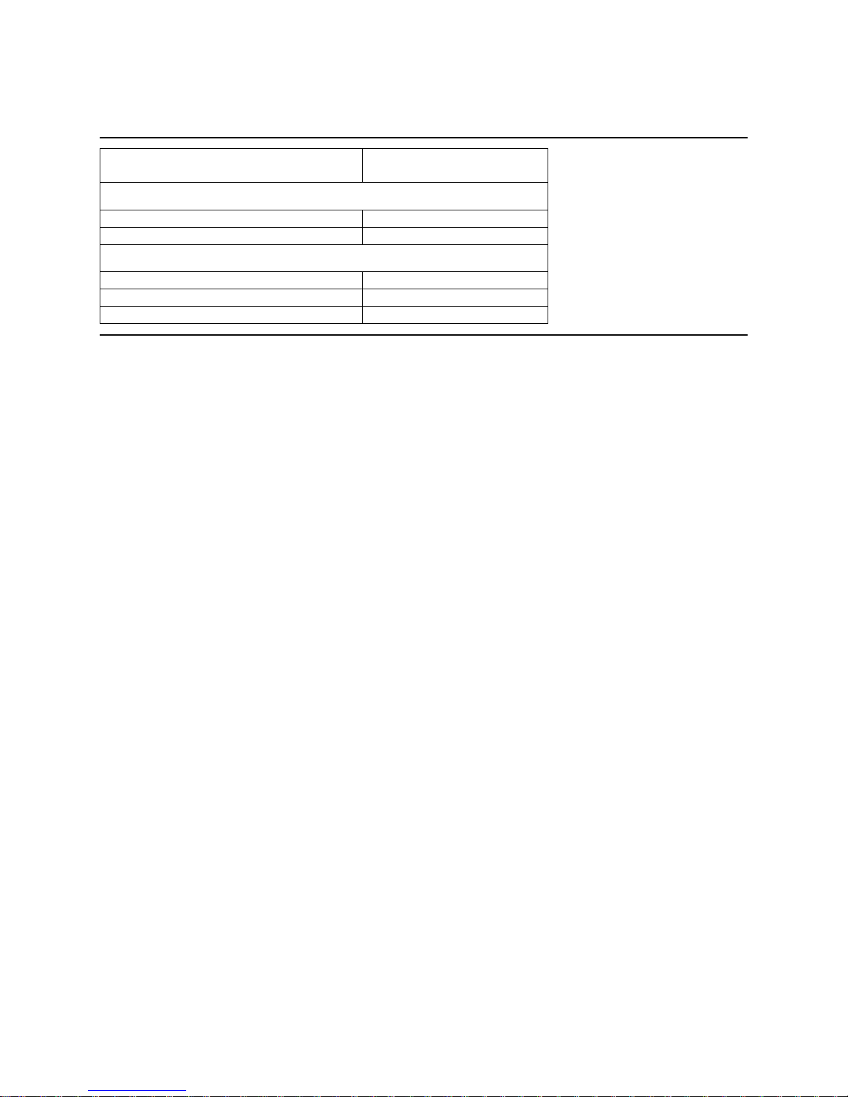
4.1 Default logical drive parameters
The default of the logical drive parameters in Identify Device data is as shown below.
IC35L060AVVA07IC35L040AVVN07IC35L020AVVN07Description
Physical Layout
61.441.120.5Label capacity (GB)
512512512Bytes per Sector
Sectors per Track
Data sectors per cylinder
Data cylinders per zone
Logical Layout
Number of Cylinders
1
2
448-928
480-984
448-928
480-984
1537-2123
1550-2020
448-928
480-984
896-1856
960-1968
1537-2123
1550-2020
448-928
321Number of Heads
211Number of Disks
1344-2784
1537-2123
161616Number of Heads
636363Number of Sectors/ Track
16,38316,38316,383
120,103,20080,418,24040,188,960Number of Sectors
61,492,838,40041,174,138,88020,576,747,520Total Logical Data Bytes
IC35L120AVVA07IC35L100AVVA07IC35L080AVVA07Description
Physical Layout
123.5102.982.3Label capacity (GB)
512512512Bytes per Sector
448-928448-928448-928Sectors per Track
654Number of Heads
332Number of Disks
2688-55682240-46401792-3712Data sectors per cylinder
1537-21231537-21231537-2123Data cylinders per zone
Logical Layout
1
161616Number of Heads
636363Number of Sectors/ Track
Number of Cylinders
2
16,38316,38316,383
241,254,720201,045,600160,836,480Number of Sectors
123,522,416,640102,935,347,20082,348,277,760Total Logical Data Bytes
Figure 1. Formatted capacity
Notes:
1
Number of cylinders: For drives with capacities greater an 8.45 GB the IDENTIFY DEVICE information
word 01 limits the number of cylinders to 16,383 per the ATA specification.
Deskstar 120GXP hard disk drive specifications
9
Page 24

2
Logical layout: Logical layout is an imaginary drive parameter (that is, the number of heads) which is
used to access the drive from the system interface. The Logical layout to Physical layout (that is, the actual Head and Sectors) translation is done automatically in the drive. The default setting can be obtained by
issuing an IDENTIFY DEVICE command
4.2 Data sheet
Low TPI modelsHigh TPI modelsDescription
627592Data transfer rate (Mbps)
1
Data buffer size
Areal density - max (Gbits/in
1
Upper 184.5 KB is used for firmware
(KB)
2
)
100100Interface transfer rate (MB/s)
2,0482,048
7,2007,200Rotational speed (RPM)
up to 12up to 12Number of buffer segments (read)
up to 56up to 56Number of buffer segments (write)
547524Recording density- max (Kbpi)
5456.7Track density (Ktpi)
29.729.7
3131Number of data bands
Figure 2. Mechanical positioning performance
Deskstar 120GXP hard disk drive specifications
10
Page 25

4.3 Drive organization
4.3.1 Drive format
Upon shipment from IBM manufacturing the drive satisfies the sector continuity in the physical format by
means of the defect flagging strategy described in Section 5.0 on page 19 in order to provide the
maximum performance to users.
4.3.2 Cylinder allocation
Data
Zone
Physical Cylinders
High TPI model Low TPI model
Blk/Trk
High TPI Low TPI
9280-17490-19380
984
9799211750-3479 1939-37561
9609123480-5199 3757-55642
9608965200-7219 5565-76873
9328887220-8969 7688-95264
9218838970-10689 9527-113345
91286410690-1239911335-133316
89085012400-1410913332-151287
88384014110-1581915129-169258
86482215820-1771916926-189229
85080617720-1941918923-2070910
83279219420-2121920710-2260111
82278721220-2291922602-2413812
80676822920-2461924139-2602413
79275224620-2616926025-2765214
76874026170-2792927653-2950115
76872527930-2957929502-3123416
74069829580-3126931235-3300917
72569131270-3295933010-3478418
70467232960-3464934785-3660919
68264864650-3632936610-3837420
65863036330-3800937375-4013921
64061438010-3968940140-4190422
62459539690-4136941905-4351923
60857641370-4296943520-4525024
57655242970-4463945251-4700425
55853344640-4630947005-4875826
54451246310-4795948759-5049127
51849347960-4963950492-5225628
49947149640-5130952257-5401029
48044851310-5289054011-55571 30
Figure 3. Cylinder allocation
Physical cylinder is calculated from the starting data track of 0. It is not relevant to logical CHS. Depending
on the capacity some of the inner zone cylinders are not allocated.
Deskstar 120GXP hard disk drive specifications
11
Page 26

Data cylinder
This cylinder contains the user data which can be sent and retrieved via read/write commands and a
spare area for reassigned data.
Spare cylinder
The spare cylinder is used by IBM manufacturing and includes data sent from a defect location.
Deskstar 120GXP hard disk drive specifications
12
Page 27

4.4 Performance characteristics
Drive performance is characterized by the following parameters:
! Command overhead
! Mechanical positioning
- Seek time
- Latency
! Data transfer speed
! Buffering operation (Look ahead/Write cache)
All the above parameters contribute to drive performance. There are other parameters that contribute to
the performance of the actual system. This specification defines the characteristics of the drive, not the
characteristics of the system throughput which depends on the system and the application.
4.4.1 Command overhead
Command overhead is defined as the time required
! from the time the command is written into the command register by a host
! to the assertion of DRQ for the first data byte of a READ command when the requested data is not
in the buffer
! excluding Physical seek time and Latency
The table below gives average command overhead.
Time (Typical) for
queued command
(ms)
0.30.3Read (Cache not hit) (from Command Write to Seek Start)
0.10.1Read (Cache hit) (from Command Write to DRQ)
0.050.015Write (from Command Write to DRQ)
not applicable0.3Seek (from Command Write to Seek Start)
Command type (Drive is in quiescent state)
Figure 4. Command overhead
Time (Typical)
(ms)
4.4.2 Mechanical positioning
4.4.2.1 Average seek time (without command overhead, including settling)
Max (ms)Typical (ms)Command Type
9.28.2Read (60 GB – 120 GB models)
9.58.5Read (20 GB & 40 GB models)
10.29.2Write
20.519.5Read (Quiet Seek mode)
21.520.5Write (Quiet Seek mode)
Figure 5. Mechanical positioning performance
Deskstar 120GXP hard disk drive specifications
13
Page 28

The terms “Typical” and “Max” are used throughout this specification with the following meanings:
Typical. The average of the drive population tested at nominal environmental and voltage conditions.
Max. The maximum value measured on any one drive over the full range of the environmental
and voltage conditions. (See Section 6.4, “Environment” on page 45 and Section 6.5, “DC Power
Requirements” on page 47.
Seek time is measured from the start of the motion of the actuator to the start of a reliable read or write
operation. "Reliable read or write" implies that error correction/recovery is not used to correct arrival problems. The average seek time is measured as the weighted average of all possible seek combinations.
max.
Weighted Average =
Σ (max. + 1 – n) (Tnin + Tn
n=1
__________________________________________________
(max. + 1) (Tnin + Tn
)
out
)
out
where: max = maximum seek length
n = seek length (1 to max)
Tn
Tn
= inward measured seek time for an n-track seek
in
= outward measured seek time for an n-track seek
out
4.4.2.2 Full stroke seek (without command overhead, including settling)
Max (ms)Typical (ms)Function
17.714.7Read (60 GB – 120 GB models)
18.315.7Read (20 GB & 40 GB models)
18.715.7Write (60 GB – 120 GB models)
19.316.3Write (20 GB & 40 GB models)
35.532.5Read (Quiet Seek mode)
36.533.5Write (Quiet Seek mode)
Figure 6. Full stroke seek time
Full stroke seek is measured as the average of 1000 full stroke seeks with a random head switch from
both directions (inward and outward).
4.4.2.3 Head switch time (Head skew)
Head switch time - typical (ms)
1.556.7 kTPI
2.054 kTPI
Figure 7. Head switch time
Head switch time is defined as the amount of time required by the fixed disk to complete a seek of the
next sequential track after reading the last sector in the current track
The measuring method is given in 4.4.5 “Throughput” on page 17.
Deskstar 120GXP hard disk drive specifications
14
Page 29

4.4.2.4 Cylinder switch time (Cylinder skew)
Cylinder switch time - typical (ms)
2.056.7 kTPI
2.554 kTPI
Figure 8. Cylinder switch time
Cylinder switch time is defined as the amount of time required by the fixed disk to access the next
sequential block after reading the last sector in the current cylinder.
The measuring method is given in 4.4.5, “Throughput” on page 17.
4.4.2.5 Single track seek time (without command overhead, including settling)
Max (ms)Typical (ms)Function
1.50.8Read
2.01.3Write
1.50.8Read (Quiet Seek mode)
2.01.3Write (Quiet Seek mode)
Figure 9. Single Track Seek Time
Single track seek is measured as the average of one (1) single track seek from every track with a random
head switch in both directions (inward and outward).
4.4.2.6 Average latency
Rotational speed
Figure 10. Latency Time
Time for a revolution
(ms)
Average latency
(ms)
4.178.37200 RPM
4.4.3 Drive ready time
Maximum (sec)Typical (sec)Power on to ready
311020 GB & 40 GB models
31960 GB & 80 GB models
3111100 GB & 120 GB models
Figure 11. Drive ready time
Ready The condition in which the drive is able to perform a media access command
(such as read, write) immediately.
Power on This includes the time required for the internal self diagnostics.
Note: Max Power On to ready time is the maximum time period that Device 0 waits for Device 1 to assert
PDIAG–.
Deskstar 120GXP hard disk drive specifications
15
Page 30
4.4.4 Data transfer speed
Data transfer speed
Disk-Buffer transfer (Zone 0)
Disk-Buffer transfer (Zone 30)
Figure 12. Data transfer speed
! Instantaneous disk-buffer transfer rate (Mbyte/sec) is derived by the following formula:
512 (Number of sectors on a track) (revolution per second)
Note: The number of sectors per track will vary because of the linear density recording.
! Sustained disk-buffer transfer rate (Mbyte/sec) is defined by considering head/cylinder change time
for read operation. This gives a local average data transfer rate. It is derived by the following formula:
(Sustained Transfer Rate) = A / (B +C +D ) where
A = 512 (number of data sectors per cylinder)
B = (number of Surfaces per cylinder – 1) (head switch time)
C = cylinder change time
D = (number of surfaces) (time for one revolution)
120 GB model
(Mbyte/sec)
57.2Instantaneous - typical
48.0Sustained - read typical
27.6Instantaneous - typical
23.2Sustained - read typical
100Buffer-Host (max)
! Instantaneous buffer-host transfer rate (Mbyte/sec) defines the maximum data transfer rate on the AT
Bus. It also depends on the speed of the host.
The method of measurement is given in 4.4.5, "Throughput" on page 17.
Deskstar 120GXP hard disk drive specifications
16
Page 31

4.4.5 Throughput
4.4.5.1 Simple sequential access
The following figure illustrates the case of the three-disk enclosure.
Max (sec)Typical (sec)Operation
0.400.38Sequential Read (Zone 0)
0.810.77Sequential Read (Zone 30)
Figure 13. Simple Sequential Access performance
The above table gives the time required to read a total of 8000h consecutive blocks (16,777,216 bytes)
accessed by 128 read commands. Typical and Max values are given by 105% and 110% of T respectively
throughout following performance description.
Note: It is assumed that a host system responds instantaneously and host data transfer is faster than
sustained data rate.
T = A + B + C + 16,777,216/D + 512/E (READ)
where
T = Calculated time (sec)
A = Command process time (Command overhead) (sec)
B = Average seek time (sec)
C = Average latency (sec)
D = Sustained disk-buffer transfer rate (byte/sec)
E = Buffer-host transfer rate (byte/sec)
4.4.5.2 Random access
The following figure illustrates the case of the three-disk enclosure.
Max (sec)Typical (sec)Operation
5855Random Read
Figure 14. Random Access Performance
The above table gives the time required to execute a total of 1000h read commands which access a single
random LBA.
T = 4096 (A + B + C + 512/D + 512/E) (READ)
where
T = Calculated time (sec)
A = Command process time (Command overhead) (sec)
B = Average seek time (sec)
C = Latency
D = Average sustained disk-buffer transfer rate (byte/sec)
E = Buffer-host transfer rate (byte/sec)
Deskstar 120GXP hard disk drive specifications
17
Page 32

4.4.6 Operating modes
4.4.6.1 Operating mode descriptions
Operating mode Description
Spin-up Start up time period from spindle stop or power down
Seek Seek operation mode
Write Write operation mode
Read Read operation mode
Unload Idle Spindle rotation at 7200 RPM with heads unloaded
Idle Spindle motor and servo system are working normally. Commands can be re-
ceived and processed immediately
Standby Actuator is unloaded and spindle motor is stopped. Commands can be received
immediately
Sleep Actuator is unloaded and spindle motor is stopped. Only soft reset or hard reset
can change the mode to standby
Note: Upon power down or spindle stop a head locking mechanism will secure the heads in the OD parking position.
4.4.6.2 Mode transition times
Mode transition times are shown below.
Transition time
RPMToFrom
Note: The command is processed immediately but there will be an actual spin down time reflecting the
seconds passed until the spindle motor stops.
Figure 15. Mode transition times
(typical )
(sec)
0.77,200IdleUnload idle
0.77,200Unload IdleIdle
Transition time
(max)
(sec)
31120 -> 7200 (3 disks)IdleStandby
ImmediatelyImmediately7200 -> 0StandbyIdle
ImmediatelyImmediately0SleepStandby
ImmediatelyImmediately0StandbySleep
Deskstar 120GXP hard disk drive specifications
18
Page 33

5.0 Defect flagging strategy
Media defects are remapped to the next available sector during the Format Process in manufacturing. The
mapping from LBA to the physical locations is calculated by an internally maintained table.
Shipped format
! Data areas are optimally used.
! No extra sector is wasted as a spare throughout user data areas.
! All pushes generated by defects are absorbed by the spare tracks of the inner zone.
NN+1 N+2 N+3
Figure 16. PList physical format
Defects are skipped without any constraint, such as track or cylinder boundary. The calculation from LBA
to physical is done automatically by internal table.
defect defect
skip
skip
Deskstar 120GXP hard disk drive specifications
19
Page 34

This page intentionally left blank.
Page 35

6.0 Specification
6.1 Electrical interface
6.1.1 Connector location
Refer to the following illustration to see the location of the connectors.
Figure 17. Connector location (2 and 3 disk model shown)
6.1.1.1 DC power connector
The DC power connector is designed to mate with AMP part number 1-480424-0 using AMP pins
part number 350078-4 (strip), part number 61173-4 (loose piece), or their equivalents. Pin assignments
are shown in the figure below.
Pin Voltage
4 3 2 1
Figure 18. Power connector pin assignments
1 +12 V
2GND
3GND
4+5V
6.1.1.2 AT signal connector
The AT signal connector is a 40-pin connector.
Deskstar 120GXP hard disk drive specifications
21
Page 36

6.1.2 Signal definition
The pin assignments of interface signals are listed in the figure below:
GND02TTLIRESET-01
key(20)GND19
GND223-stateODMARQ21
GND24TTLIDIOW-(*)23
GND26TTLIDIOR-(*)25
GND30TTLIDMACK-29
GND40OCI/ODASP-39
TypeI/OSIGNALPINTypeI/OSIGNALPIN
3-stateI/ODD8043-stateI/ODD703
3-stateI/ODD9063-stateI/ODD605
3-stateI/ODD10083-stateI/ODD507
3-stateI/ODD11103-stateI/ODD409
3-stateI/ODD12123-stateI/ODD311
3-stateI/ODD13143-stateI/ODD213
3-stateI/ODD14163-stateI/ODD115
3-stateI/ODD15183-stateI/ODD017
TTLICSEL283-stateOIORDY(*)27
OCOIOCS16-(**)323-stateOINTRQ31
OCI/OPDIAG-34TTLIDA133
TTLIDA236TTLIDA035
TTLICS1-38TTLICSO-37
Figure 19. Table of signals
Notes:
1. "O" designates an output from the drive.
2. "I" designates an input to the drive.
3. "I/O" designates an input/output common.
4. "OC" designates open-collector or open-drain output.
5. The signal lines marked with (*) are redefined during the Ultra DMA protocol to provide special
functions. These lines change from the conventional to special definitions at the moment the Host
decides to allow a DMA burst if the Ultra DMA transfer mode was previously chosen via
SetFeatures. The Drive becomes aware of this change upon assertion of the DMACK- line. These
lines revert back to their original definitions upon the deassertion of DMACK- at the termination of
the DMA burst.
6. (**) complies with ATA-2.
Write Operation
Read Operation
Special Definition
(for Ultra DMA)
DDMARDY-
HSTROBE
STOP
HDMARDY-
DSTROBE
STOP
Conventional Definition
IORDY
DIOR-
DIOW-
DIORIORDY
DIOW-
Figure 20. Signal special definitions for Ultra DMA
Deskstar 120GXP hard disk drive specifications
22
Page 37

DD0-DD15 16-bit bi-directional data bus between the host and the drive. The lower 8 lines, DD00-07,
are used for Register and ECC access. All 16 lines, DD00-15, are used for data transfer.
These are 3-State lines with 24 mA current sink capability.
DA0-DA2 Address used to select the individual register in the drive.
CS0- Chip select signal generated from the Host address bus. When active, one of the
Command Block Registers (Data, Error {Features when written}, Sector Count, Sector
Number, Cylinder Low, Cylinder High, Drive/Head and Status {Command when written}
register) can be selected. (See Figure 43 on page 38.)
CS1- Chip select signal generated from the Host address bus. When active one of the Control
Block Registers (Alternate Status {Device Control when written} and Drive Address
register) can be selected. (See Figure 43 on page 38.)
RESET- This line is used to reset the drive. It shall be kept in Low logic state during power up and
in High thereafter.
DIOW- Its rising edge holds data from the host data bus to a register or data register of the drive.
DIOR- When low, this signal enables data from a register or data register of the drive onto data
bus. The data on the bus shall be latched on the rising edge of DIOR-.
INTRQ Interrupt is enabled only when the drive is selected and the host activates the nIEN bit in
the Device Control Reg. Otherwise, this signal is in high impedance state regardless of
the state of the IRQ bit. The interrupt is set when the IRQ bit is set by the drive CPU. IRQ
is reset to zero by a host read of the status register or a write to the Command Reg. This
signal is a 3-State line with 24 mA sink capability.
IOCS16- Indication to the host that a 16-bit wide data register has been addressed and that the
drive is prepared to send or receive a 16-bit wide data word. This signal is an Open-drain
output with 24 mA sink capability and an external resistor is needed to pull this line to 5
volts.
DASP- This is a time-multiplexed signal which indicates that a drive is active, or that device 1 is
present. This signal is driven by Open-Drain driver and internally pulled up to 5 volts
through a 10kΩ resistor.
During Power-On initialization or after RESET- is negated, DASP- shall be asserted by
Device 1 within 400 ms to indicate that device 1 is present. Device 0 shall allow up to
450 ms for device 1 to assert DASP-. If device 1 is not present, device 0 may assert
DASP- to drive a LED indicator.
DASP- shall be negated following acceptance of the first valid command by device 1. At
anytime after negation of DASP-, either drive may assert DASP- to indicate that a drive is
active.
PDIAG- PDIAG- shall be asserted by device 1 to indicate to device 0 that it has completed diag-
nostics. This line is pulled-up to 5 volts in the drive through a 10kΩ resistor.
Following a Power On Reset, software reset, or RESET-, drive 1 shall negate PDIAG-
within 1 ms (to indicate to device 0 that it is busy). Drive 1 shall then assert PDIAG- within
30 seconds to indicate that it is no longer busy and is able to provide status.
Following the receipt of a valid Execute Drive Diagnostics command, device 1 shall
negate PDIAG- within 1 ms to indicate to device 0 that it is busy and has not yet passed
its drive diagnostics. If device 1 is present, device 0 shall wait up to 6 seconds from the
receipt of a valid Execute Drive Diagnostics command for drive 1 to assert PDIAG-.
Device 1 should clear BSY before asserting PDIAG-, as PDIAG- is used to indicate that
device 1 has passed its diagnostics and is ready to post status.
Deskstar 120GXP hard disk drive specifications
23
Page 38

If device 1 did not assert DASP- during reset initialization, device 0 shall post its own
status immediately after it completes diagnostics and clear the device 1 Status register to
00h. Device 0 may be unable to accept commands until it has finished its reset procedure
and is ready (DRDY=1).
Device 1 shall release PDIAG-/CBLID- no later than after the first command following a
power on or hardware reset sequence so that the host may sample PDIAG-/CBLID- in
order to detect the presence or absence of an 80-conductor cable assembly.
CSEL (Cable Select) (Optional)
The drive is configured as either Device 0 or 1 depending upon the value of CSEL.
! If CSEL is grounded, the device address is 0.
! If CSEL is open, the device address is 1.
KEY Pin position 20 has no connection pin. It is recommended to close the respective position
of the cable connector in order to avoid incorrect insertion by mistake.
IORDY This signal is negated to extend the host transfer cycle when a drive is not ready to
respond to a data transfer request and may be negated when the host transfer cycle is
less than 240 ns for PIO data transfer. This signal is an open-drain output with 24 mA sink
capability and an external resistor is needed to pull this line to 5 volts.
DMACK- This signal shall be used by the host in response to DMARQ to either acknowledge that
data has been accepted or that data is available.
This signal is internally pulled up to 5 V through a 15 KΩ resistor. The tolerance of the
resistor value is –50% to +100%.
DMARQ This signal, used for DMA data transfers between host and drive, shall be asserted by the
drive when it is ready to transfer data to or from the host. The direction of data transfer is
controlled by DIOR- and DIOW-. This signal is used on a handshake manner with
DMACK-. This signal is a 3-state line with 24mA sink capability and internally pulled down
to GND through 10 KΩ resistor.
HDMARDY- (Ultra DMA)
This signal is used only for Ultra DMA data transfers between the host and the device.
HDMARDY- is a flow control signal for Ultra DMA data in bursts. This signal is held
asserted by the host to indicate to the device that the host is ready to receive Ultra DMA
data in transfers. The host may negate HDMARDY- to pause an Ultra DMA data in
transfer.
HSTROBE (Ultra DMA)
This signal is used only for Ultra DMA data transfers between the host and the device.
HSTROBE is the data out strobe signal from the host for an Ultra DMA data out transfer.
Both the rising and falling edge of HSTROBE latch the data from DD(15:0) into the
device. The host may stop toggling HSTROBE to pause an Ultra DMA data out transfer.
STOP (Ultra DMA)
This signal is used only for Ultra DMA data transfers between the host and the device.
STOP shall be asserted by the host prior to initiation of an Ultra DMA burst. STOP shall
be negated by the host before data is transferred in an Ultra DMA burst. Assertion of
STOP by the host during or after data transfer in an Ultra DMA mode signals the
termination of the burst.
Deskstar 120GXP hard disk drive specifications
24
Page 39

DDMARDY- (Ultra DMA)
This signal is used only for Ultra DMA data transfers between the host and the device.
DDMARDY- is a flow control signal for Ultra DMA data out bursts. This signal is held
asserted by the device to indicate to the host that the device is ready to receive Ultra
DMA data out transfers. The device may negate DDMARDY- to pause an Ultra DMA data
out transfer.
DSTROBE (Ultra DMA)
This signal is used only for Ultra DMA data transfers between the host and the device.
DSTROBE is the data in strobe signal from the device for an Ultra DMA data in transfer.
Both the rising and falling edge of DSTROBE latch the data from DD(15:0) into the host.
The device may stop toggling DSTROBE to pause an Ultra DMA data in transfer.
Device Termination
The termination resistors on the device side are implemented on the drive side as follows:
!33 Ω for DD0 thru DD15, DMARQ, INTRQ
!82 Ω for CS0-, CS1-, DA0, DA1, DA2, DIOR-, DIOW-, DMACK-
!22 Ω for IORDY
6.1.3 Interface logic signal levels
The interface logic signal has the following electrical specifications:
2.0 V min.Input High VoltageInputs
0.8 V max.Input Low Voltage
2.4 V min.Output High VoltageOutputs
0.5 V max.Output Low Voltage
Deskstar 120GXP hard disk drive specifications
25
Page 40

6.2 Signal timings
6.2.1 Reset timings
Drive reset timing.
RESET-
BUSY
Figure 21. System reset timing chart
t10
t14
Max (sec)Min (sec)PARAMETER DESCRIPTION
25RESET low widtht10
31–RESET high to not BUSYt14
Figure 22. System reset timing
Deskstar 120GXP hard disk drive specifications
26
Page 41

6.2.2 PIO timings
The PIO cycle timings meet Mode 4 of the ATA/ATAPI-6 description.
CS(1:0)
DA(2:0)
t9
DIOR-,
DIOW-
Write data
DD(15:0)
Read data
DD(15:0)
IOCS16-(*)
IORDY
Figure 23. PIO cycle timings chart
t1
t1
t7(*)
tA
t0
t2 t2i
t3 t4
t5 t6
t8(*)
tB
(*) Up to ATA- 2 (mo de-0,1,2)
Figure 24. PIO cycle timings
MAX (ns)MIN (ns)PARAMETER DESCRIPTION
–120Cycle timet0
–25Address valid to DIOR-/DIOW– setupt1
–70DIOR–/DIOW– pulse widtht2
–25DIOR–/DIOW– recovery timet2i
–20DIOW– data setupt3
–10DIOW– data holdt4
–20DIOR– data setupt5
–5DIOR– data holdt6
40–Address valid to IOCS16– assertiont7(*)
30–Address invalid to IOCS16– negationt8(*)
-10DIOR–/DIOW– to address valid holdt9
35–IORDY set up timetA
1250–IORDY pulse widthtB
Deskstar 120GXP hard disk drive specifications
27
Page 42

6.2.2.1 Write DRQ interval time
For write sectors and write multiple operations 3.8 µs is inserted from the end of negation of the DRQ bit
until setting of the next DRQ bit.
6.2.2.2 Read DRQ interval time
For read sectors and read multiple operations the interval from the end of negation of the DRQ bit until
setting of the next DRQ bit is as follows:
! In the event that a host reads the status register only before the sector or block transfer DRQ
interval, the DRQ interval 4.2 µs
! In the event that a host reads the status register after or both before and after the sector or block
transfer, the DRQ interval is 11.5 µs
Deskstar 120GXP hard disk drive specifications
28
Page 43

6.2.3 Multiword DMA timings
The Multiword DMA timing meets Mode 2 of the ATA/ATAPI-6 description.
CS0-/CS1-
DMARQ
DMACK-
DIOR-/DIOW-
READ DATA
WRITE DATA
Figure 25. Multiword DMA cycle timing chart
tM
tI tD tKR/tKW
tE
tG
tN
tLR/tLW
tJ
t0
tFtG
tH
tZ
MAX (ns)MIN (ns)PARAMETER DESCRIPTION
–120Cycle timet0
–70DIOR–/DIOW– asserted pulse widthtD
50–DIOR– data accesstE
–5DIOR– data holdtF
–20DIOR–/DIOW– data setuptG
–10DIOW– data holdtH
–0DMACK– to –DIOR–/DIOW– setuptI
–5DIOR–/DIOW– to DMACK– holdtJ
–25DIOR–/DIOW– negated pulse widthtKR/tKW
35–DIOR–/DIOW– to DMARQ– delaytLR/tLW
–25CS (1:0) valid to DIOR–/DIOW–tM
–10CS (1:0) holdtN
25–DMACK– to read data releasedtZ
Figure 26. Multiword DMA cycle timings
Deskstar 120GXP hard disk drive specifications
29
Page 44

6.2.4 Ultra DMA timings
The Ultra DMA timing meets Mode 0,1,2,3 4, and 5 of the Ultra DMA Protocol.
6.2.4.1 Initiating Read DMA
DMARQ
tUI
DMACK-
tACK
tENV
STOP
tACK
tENV
HDMARDY-
tZIORDY
DSTROBE
tAZ
DD(15:00)
xxxxxxxxxxxxxxxxxxxxxxxxx
Host drives DD
Figure 27. Ultra DMA cycle timing chart (Initiating Read)
PARAMETER DESCRIPTION
(all values in ns)
tZIORDY
tAZ
tZAD
tDZFS
Minimum time before driving
IORDY
Maximum time allowed for
output drivers to release
Maximum time allowed for
output drivers to assert
Time from data output released-to-driving until the first
transition of critical timing
t2CYC
tFS
tCYC tCYC
tDZFS
tZAD
xxx xxx xxx
RD Data
tDS
tDH
RD Data
tDS
Device drives DD
20
–20–20–20–20Setup time before –DMACK tACK
tDH
RD Data
MODE5MODE4MODE3MODE2MODE1MODE0
MAXMIN MAXMIN MAXMIN MAXMIN MAXMIN MAXMIN
–0–0–000–0–0Unlimited interlock timetUI
–20–
502055205520702070207020Envelope timetENV
–0–0–0–0–0–0
90012001300170020002300First DSTROBE timetFS
–17–25–39–54–73–112Cycle timetCYC
–38–57–86–115–153–230Two cycle timet2CYC
10–10–10–10–10–10–
–0–0–0–0–0–0
–4–5–7–7–10–15Data setup time (at host)tDS
–4.6–5–5–5–5–5Data hold time (at host)tDH
-25-6.7-20-31-48-70
Figure 28. Ultra DMA cycle timings (Initiating Read)
Deskstar 120GXP hard disk drive specifications
30
Page 45

6.2.4.2 Host Pausing Read DMA
DMARQ
DMACK-
STOP
tSR
HDMARDY-
tRFS
DSTROBE
Figure 29. Ultra DMA cycle timing chart (Host pausing Read)
PARAMETER DESCRIPTION
(all values in ns)
Note: When a host does not satisfy tSR timing, it should be ready to receive two more data words after
HDMARDY– is negated.
Figure 30. Ultra DMA cycle timings (Host pausing Read)
MODE5MODE4MODE3MODE2MODE1MODE0
MAXMIN MAXMIN MAXMIN MAXMIN MAXMIN MAXMIN
––––––20–30–50–DSTROBE to HDMARDY– timetSR
50–60–60–60–70–75–HDMARDY– to final DSTROBE timetRFS
Deskstar 120GXP hard disk drive specifications
31
Page 46

6.2.4.3 Host Terminating Read DMA
DMARQ
tLI
DMACK-
tRP
STOP
HDMARDY-
tRFS
tLI
DSTROBE
DD(15:00)
xxx
RD Data
xxxxxxxxxxxxxxxxxx
Device drives DD
Figure 31. Ultra DMA cycle timing chart (Host terminating Read)
tAZ
tZAH
tMLI
xxx
tACK
tACK
tIORDYZ
tCHtCS
CRC
xxxxxxxxxx
Host drives DD
PARAMETER DESCRIPTION
(all values in ns)
tRFS
tAZ
tZAH
tMLI
tCS
tCH
tIORDYZ
Figure 32. Ultra DMA cycle timings (Host terminating Read)
HDMARDY– to final
DSTROBE time
Maximum time allowed for
output drivers to release
Minimum delay time required
for output
Interlocking time with
minimum
CRC word setup time (at
device side)
CRC word hold time (at device
side)
Maximum time before
releasing IORDY
Deskstar 120GXP hard disk drive specifications
32
MODE5MODE4MODE3MODE2MODE1MODE0
MAXMIN MAXMIN MAXMIN MAXMIN MAXMIN MAXMIN
50–60–60–60–70–75–
–85–100–100–100–125–160Ready to pause timetRP
75010001000150015001500Limited interlock timetLI
10–10–10–10–10–10–
–20–20–20–20–20–20
–20–20–20–20–20–20
–5–5–7–7–10–15
–5–5–5–5–5–5
–20–20–20–20–20–20Hold time for DMACK –tACK
20–20–20–20–20–20–
Page 47

6.2.4.4 Device Terminating Read DMA
DMARQ
tSS
DMACK-
tLI
STOP
tLI
HDMARDY-
tLI
DSTROBE
tAZ
DD(15:00)
xxxxx
xxxxxxxxxxxxxxxxxx
tZAH
Device drives DD
Figure 33. Ultra DMA cycle timing chart (Device terminating Read)
tMLI
tIORDYZ
CRC
Host drives DD
tACK
tACK
tCHtCS
xxxxxxxxxx
PARAMETER DESCRIPTION
(all values in ns)
tSS
tAZ
tZAH
tCS
tCH
tIORDYZ
Figure 34. Ultra DMA cycle timings (Device Terminating Read)
Time from DSTROBE edge to
negation of DMARQ
Maximum time allowed for
output drivers to release
Minimum delay time required
for output
CRC word setup time (at device
side)
CRC word hold time (at device
side)
Maximum time before releasing
IORDY
Deskstar 120GXP hard disk drive specifications
33
MODE5MODE4MODE3MODE2MODE1MODE0
MAXMIN MAXMIN MAXMIN MAXMIN MAXMIN MAXMIN
–50–50–50–50–50–50
75010001000150015001500Limited interlock timetLI
10–10–10–10–10–10–
–20–20–20–20–20–20
–20–20–20–20–20–20Interlock time with minimumtMLI
–5–5–7–7–10–15
–5–5–5–5–5–5
–20–20–20–20–20–20Hold time after DMACK–tACK
20–20–20–20–20–20–
Page 48

6.2.4.5 Initiating Write DMA
DMARQ
tUI
DMACK-
tACK
tENV
STOP
tZIORDY tLI
DDMARDY-
tACK
HSTROBE
DD(15:0)
xxxxxxxxxxxxxxxxxxxxxxxxxxxxx xx
Figure 35. Ultra DMA cycle timing chart (Initiating Write)
PARAMETER DESCRIPTION
(all values in ns)
tZIORDY
Minimum time before driving
IORDY
tUI
WT Data
Host drives DD
t2CYC
tCYC tCYC
tDH
tDS
xxx
WT Data
xxx
tDS
tDH
WT Data
MODE5MODE4MODE3MODE2MODE1MODE0
MAXMIN MAXMIN MAXMIN MAXMIN MAXMIN MAXMIN
–0–0–0–0–0–0Unlimited interlock timetUI
–20–20–20–20–20–20Setup time before DMACK–tACK
502055205520702070207020Envelope timetENV
–0–0–0–0–0–0
75010001000150015001500Limited interlock timetLI
–16.8–25–39–54–73–112Cycle timetCYC
–38–57–86–115–154–230Two Cycle timet2CYC
–4–5–7–7–10–15Data setup time (at device side)tDS
–4.6–5–5–5–5–5Data hold time (at device side)tDH
Figure 36. Ultra DMA cycle timings (Initiating Write)
Deskstar 120GXP hard disk drive specifications
34
Page 49

6.2.4.6 Device Pausing Write DMA
DMARQ
DMACK-
STOP
tSR
DDMARDY-
tRFS
HSTROBE
Figure 37. Ultra DMA cycle timing chart (Device Pausing Write)
MODE5MODE4MODE3MODE2MODE1MODE0
-
tSR
tRFS
PARAMETER DESCRIPTION
(all values in ns)
–––20–30–50–HSTROBE to DDMARDY–
response time
time
Note: When a device does not satisfy the tSR timing, it shall be ready to receive two more strobes after
DDMARDY– is negated.
Figure 38. Ultra DMA cycle timings (Device Pausing Write)
MAXMIN MAXMIN MAXMIN MAXMIN MAXMIN MAXMIN
––
50–60–60–60–70–75–DDMARDY– to final HSTROBE
Deskstar 120GXP hard disk drive specifications
35
Page 50

6.2.4.7 Device Terminating Write DMA
DMARQ
tRP
tLI
DMACK-
STOP
DDMARDY-
tRFS
tLI
HSTROBE
DD(15:00)
xxx
WT Data
xxxxxxxxxxxxxxxxxxxxxxxxxx
Host drives DD
Figure 39. Ultra DMA cycle timing chart (Device Terminating Write)
tMLI
tIORDYZ
CRC
tACK
tACK
tCHtCS
xxxxxxxxxx
PARAMETER DESCRIPTION
(all values in ns)
tRFS
tCS
tCH
tIORDYZ
Figure 40. Ultra DMA cycle timings (Device terminating Write)
DDMARDY to final HSTROBE
time
CRC word setup time (at device
side)
CRC word hold time (at device
side)
Maximum time before releasing
IORDY
MODE5MODE4MODE3MODE2MODE1MODE0
MAXMIN MAXMIN MAXMIN MAXMIN MAXMIN MAXMIN
50–60–60–60–70–75–
–85–100–100–100–125–160Ready to pause timetRP
75010001000150015001500Limited interlock timetLI
–20–20–20–20–20–20Interlock time with minimumtMLI
–5–5–7–7–10–15
–5–5–5–5–5–5
–20–20–20–20–20–20Hold time for –DMACKtACK
20–20–20–20–20–20–
Deskstar 120GXP hard disk drive specifications
36
Page 51

6.2.4.8 Host Terminating Write DMA
DMARQ
tLI
DMACK-
tSS
STOP
tLI
DDMARDY-
tLI
HSTROBE
DD(15:00)
xxxxxxxxxxxxxxxxxxxxxxxxxxxxxxxxxxxxx
Host drives DD
Figure 41. Ultra DMA cycle timing chart (Host Terminating Write)
tMLI
tIORDYZ
CRC
tACK
tACK
tCHtCS
xxxxxxxxxx
PARAMETER DESCRIPTION
(all values in ns)
tSS
tCS
tCH
tIORDYZ
Figure 42. Ultra DMA cycle timings (Host Terminating Write)
Time from HSTROBE to edge
assertion of STOP
CRC word setup time (at device
side)
CRC word hold time (at device
side)
Maximum time before releasing
IORDY
MODE5MODE4MODE3MODE2MODE1MODE0
MAXMIN MAXMIN MAXMIN MAXMIN MAXMIN MAXMIN
–50–50–50–50–50–50
75010001000150015001500Limited interlock timetLI
–20–20–20–20–20–20Interlock time with minimumtMLI
–5–5–7–7–10–15
–5–5–5–5–5–5
–20–20–20–20–20–20Hold time for DMACK–tACK
20–20–20–20–20–20–
Deskstar 120GXP hard disk drive specifications
37
Page 52

6.2.5 Addressing of registers
The host addresses the drive through a set of registers called the Task File. These registers are mapped
into the I/ O space of the host. Two chip select lines (CS0– and CS1–) and three address lines (DA0-02)
are used to select one of these registers, while a DIOR– or DIOW– is provided at the specified time.
The CS0– is used to address Command Block registers. while the CS1– is used to address Control Block
registers.
The following table shows the I/ O address map.
DIOW– = 0 (Write)DIOR– = 0 (Read)DA0DA1DA2CS1–CS0–
Command Block Registers
Data Reg.Data Reg.00010
Features Reg.Error Reg.10010
Sector count Reg.Sector count Reg.01010
Sector number Reg.Sector number Reg.11010
Cylinder low Reg.Cylinder low Reg.00110
Cylinder high Reg.Cylinder high Reg.10110
Drive/Head Reg.Drive/Head Reg.01110
Command Reg. Status Reg. 11110
Control Block Registers
Device control Reg.Alt. Status Reg.01101
Figure 43. I/O address map
Note: "Addr" field is shown as an example.
During DMA operation (from writing to the command register until an interrupt) not all registers are acces-
sible. For example, the host is not supposed to read status register contents before interrupt (the value is
invalid).
6.2.6 Cabling
The maximum cable length from the host system to the drive plus circuit pattern length in the host system
shall not exceed 18 inches.
For higher data transfer application (>8.3 MB/s) a modification in the system design is recommended to
reduce cable noise and cross-talk, such as a shorter cable, bus termination, or a shielded cable.
For systems operating with Ultra DMA mode 3, 4, and 5, 80-conductor ATA cable assembly (SFF-8049)
shall be used.
Deskstar 120GXP hard disk drive specifications
38
Page 53

6.3 Jumper settings
6.3.1 Jumper pin location
Figure 44. Jumper pin location (2 and 3 disk model shown)
6.3.2 Jumper pin identification
Jumper pins
Pin I
Figure 45. Jumper pin identification (2 and 3 disk model shown)
Pin A
DERA001.p rz
Pin B
Deskstar 120GXP hard disk drive specifications
39
Page 54

6.3.3 Jumper pin assignment
There are four jumper settings as shown in the following sections:
! 16 logical head default (normal use)
! 15 logical head default
! 2 GB/32 GB clip
! Power up in standby
Within each of these four jumper settings the pin assignment selects Device 0, Device 1, Cable Selection,
or Device 1 Slave Present as shown in the following figures.
The Device 0 setting automatically recognizes device 1 if it is present.
The Device 1 Slave Present setting is for a slave device that does not comply with the ATA specification.
Note: In conventional terminology "Device 0" designates a Master and "Device 1" designates a Slave.
RSV
IGECA
Figure 46. Jumper pin assignment
GND
H
DS
GND GND RSV
BF
RS V
CS/SP
D
GND
Deskstar 120GXP hard disk drive specifications
40
Page 55

6.3.4 Jumper positions
6.3.4.1 16 logical head default (normal use)
The figure below shows the jumper positions used to select Device 0, Device 1, Cable Selection, or
Device 1 (Slave) Present.
I
G
HFDB
ECA
DEV ICE 0 ( Master)
I
G
HFDB
I
G
HFDB
I
G
HFDB
I
G
HFDB
Figure 47. Jumper positions for normal use
Notes:
1. To enable the CSEL mode (Cable Selection mode) the jumper block must be installed at E-F. In the
CSEL mode the drive address is determined by AT interface signal #28 CSEL as follows:
!
When CSEL is grounded or at a low level, the drive address is 0 (Device 0).
!
When CSEL is open or at a high level, the drive address is 1 (Device 1).
2. In CSEL mode, installing or removing the jumper blocks at A-B or C-D position does not affect any
selection of Device or Cable Selection mode.
3. The shipping default position is the Device 0 position.
ECA
ECA
ECA
ECA
DEVICE 1 (Slave)
CABLE SEL
DEVICE 1 (Slave) Present
Shipping Default Condition
(DEVICE 0)
Deskstar 120GXP hard disk drive specifications
41
Page 56

6.3.4.2 15 logical head default
The figure below shows the jumper positions used to select Device 0, Device 1, Cable Selection, or
Device 1 (Slave) Present setting 15 logical heads instead of default 16 logical head models.
I
G
ECA
HFDB
I
G
ECA
HFDB
I
G
ECA
HFDB
I
G
ECA
HFDB
Figure 48. Jumper positions for 15 logical head default
D E V ICE 0 (Ma s te r)
DEVICE 1 (Slave)
CABLE SEL
DEVICE 1 (Slave) Present
Notes:
1. To enable the CSEL mode (Cable Selection mode) the jumper block must be installed at E-F. In the
CSEL mode, the drive address is determined by AT interface signal #28 CSEL as follows:
!
When CSEL is grounded or at a low level, the drive address is 0 (Device 0).
!
When CSEL is open or at a high level, the drive address is 1 (Device 1).
2. In CSEL mode, installing or removing the jumper blocks at A-C or B-D position does not affect any
selection of Device or Cable Selection mode.
Deskstar 120GXP hard disk drive specifications
42
Page 57

6.3.4.3 Capacity clip to 2GB/32GB
The figure below shows the jumper positions used to select Device 0, Device 1, Cable Selection, or
Device 1 (Slave) Present while setting the drive capacity down either to 2GB or 32GB for the purpose of
compatibility.
I
G
ECA
HFDB
I
G
ECA
HFDB
I
G
ECA
HFDB
I
G
ECA
HFDB
Figure 49. Jumper positions for capacity clip to 2GB/32GB
D E V ICE 0 (Ma s te r)
DEVICE 1 (Slave)
CABLE SEL
DEVICE 1 (Slave) Present
Notes:
For the 20-GB model (factory default capacities less than 32GB):
The jumper setting acts as a 2GB clip which clips the CHS to 4096/16/63. The LBA is unchanged from
the factory default setting (dependent on the particular model).
For all other models (factory default capacities greater than 32GB):
The jumper setting acts as a 32GB clip which clips the LBA to 66055248. The CHS is unchanged from
the factory default of 16383/16/63.
Deskstar 120GXP hard disk drive specifications
43
Page 58

6.3.4.4 Power Up In Standby
The figure below shows the jumper positions used to select Device 0, Device 1, Cable Selection, or
Device 1 (Slave) Present to enable Power Up In Standby.
I
G
ECA
HFDB
I
G
ECA
HFDB
I
G
ECA
HFDB
I
G
ECA
HFDB
Figure 50. Jumper settings for Disabling Auto Spin
D E V ICE 0 (Ma s te r)
DEVICE 1 (Slave)
CABLE SEL
DEVICE 1 (Slave) Present
Notes:
1. These jumper settings are used for limiting power supply current when multiple drives are used.
2. Command to spin up is SET FEATURES (subcommand 07h). Refer to 12.28 Set Features.
3. To enable the CSEL mode (Cable Selection mode) the jumper block must be installed at E-F. In
CSEL mode, the drive address is determined by AT interface signal #28 as follows:
!
When CSEL is grounded or at a low level, the drive address is 0 (Device 0).
!
When CSEL is open or at a high level, the drive address is 1 (Device 1).
Deskstar 120GXP hard disk drive specifications
44
Page 59

6.4 Environment
6.4.1 Temperature and humidity
Operating conditions
Temperature
Relative humidity
Maximum wet bulb temperature
Maximum temperature gradient
Altitude
Non operating conditions
Temperature
Relative humidity
Maximum wet bulb temperature
Altitude
Figure 51. Temperature and humidity
Notes:
1. The system is responsible for providing sufficient ventilation to maintain a surface temperature
below 60°C at the center of the top cover of the drive.
2. Non condensing conditions should be maintained at any time.
3. Maximum storage period within shipping package is one year,
5 to 55°C
8 to 90% non-condensing
29.4°C non-condensing
15°C/Hour
–300 to 3,048 m
–40 to 65°C
5 to 95% non-condensing
35°C non-condensing
–300 to 12,000 m
Deskstar 120GXP hard disk drive specifications
45
Page 60

100
Environment Specification
36C/95%
90
80
31C/90%
Wet Bulb 35C
70
60
50
40
30
Relative Humidity (%)
20
10
0
Nonoperating
-40 -20 0 20 40 60
Operating
Wet Bulb 29.4C
65C/14%
55C/15%
Temperature (C)
Figure 52. Limits of temperature and humidity
Note: Storage temperature range is 0° to 65°.
6.4.2 Corrosion test
The drive shows no sign of corrosion inside and outside of the hard disk assembly and is functional after
being subjected to seven days at 50°C with 90% relative humidity.
Deskstar 120GXP hard disk drive specifications
46
Page 61

6.5 DC power requirements
The following voltage specifications apply at the power connector of the drive. Damage to the drive
electronics may result if the power supply cable is connected or disconnected while power is being applied
to the drive (no hot plug/unplug is allowed). Connections to the drive should be made in a low voltage, isolated secondary circuit (SELV). There is no special power on/off sequencing required.
6.5.1 Input voltage
During run and spin upInput voltage
Absolute max
spike voltage
1
–0.3 to 7V5V ± 5%+5 Volts Supply
–0.3 to 15V12V +10% –8%+12 Volts Supply
Figure 53. Input voltage
Note: To avoid damage to the drive electronics, power supply voltage spikes must not exceed specifications.
6.5.2 Power supply current (typical)
Power supply current of
120 GB and 100 GB models
Seek average
Random R/W average
1
2
+12 Volts [mA]+5 Volts [mA]
Std DevPop MeanStd DevPop Mean(values in milliamps. RMS)
463905310Idle average
3037026370Idle ripple (peak-to-peak)
262205160Low RPM idle
23230650Low RPM idle ripple
342805160Unload idle average
27240650Unload idle ripple
424706380
4682019600Seek peak
4259010470
110180022790Random R/W peak
3647010470Silent R/W average
4682022790Silent R/W peak
Total
[W]
6.2
3.4
4.2
7.5
9.4
8.0
86186720740Start up (max)
1.01153160Standby average
0.91153150Sleep average
Figure 54. Power supply current of 120 GB and 100 GB models
Except for a peak of less than 100 µs duration
1
Random seeks at 40% duty cycle
2
Seek duty = 30%, W/R duty = 45%, Idle Duty = 25%
Deskstar 120GXP hard disk drive specifications
47
Page 62

Power supply current of 80 GB
and 60 GB models
Seek average
Random R/W average
Figure 55. Power supply current of 80 GB and 60 GB models
1
2
+12 Volts [mA]+5 Volts [mA]
Std DevPop MeanStd DevPop Mean(values in milliamps. RMS)
333209310Idle average
3332015370Idle ripple (peak-to-peak)
201704150Low RPM Idle
29230450Low RPM Idle Ripple
292604150Unload Idle average
22230445Unload Idle Ripple
3140010380
4274020600Seek peak
2854012470
130170018790Random R/W peak
2841013470Silent R/W average
4274018790Silent R/W peak
Total
[W]
5.4
2.8
3.9
6.7
8.8
7.3
98180021740Start up (max)
1.01154160Standby average
0.91154150Sleep average
Power supply current of 40 GB
and 20 GB models
Seek average
Random R/W average
Figure 56. Power supply current of 40 GB and 20 GB models
1
2
Except for a peak of less than 100 µs duration
1
Random seeks at 40% duty cycle
2
Seek duty = 30%, W/R duty = 45%, Idle Duty = 25%
+12 Volts [mA]+5 Volts [mA]
Std DevPop MeanStd DevPop Mean(values in millia mps. RMS)
162703303Idle average
3031215273Idle ripple (peak-to-peak)
71403156Low RPM idle
45333649Low RPM idle ripple
192202157Unload idle average
24216649Unload idle ripple
143364364
7050550Seek peak
48812454
6
33
29152043738Random R/W peak
3135012459Silent R/W average
670543738Silent R/W peak
Total
[W]
4.8
2.5
3.4
5.9
8.1
6.5
15170025713Start up (max)
1.01153156Standby average
0.91156139Sleep average
Deskstar 120GXP hard disk drive specifications
48
Page 63

6.5.3 Power supply generated ripple at drive power connector
MHzMaximum (mV pp)
0-10100+5V DC
0-10150+12V DC
Figure 57. Power supply generated ripple at drive power connector
During drive start up and seeking 12-volt ripple is generated by the drive (referred to as dynamic loading).
If the power of several drives is daisy chained together, the power supply ripple plus the dynamic loading
of the other drives must remain within the above regulation tolerance. A common supply with separate
power leads to each drive is a more desirable method of power distribution.
To prevent external electrical noise from interfering with the performance of the drive, the drive must be
held by four screws in a user system frame which has no electrical level difference at the four screws
position and has less than ±300 millivolts peak to peak level difference to the ground of the drive power
connector.
Deskstar 120GXP hard disk drive specifications
49
Page 64

6.6 Reliability
6.6.1 Data integrity
No more than one sector is lost at Power loss condition during the write operation when the write cache
option is disabled. If the write cache option is active, the data in write cache will be lost. To prevent the
loss of customer data, it is recommended that the last write access before power off be issued after setting
the write cache off.
6.6.2 Cable noise interference
To avoid any degradation of performance throughput or error rate when the interface cable is routed on
top or comes in contact with the HDA assembly, the drive must be grounded electrically to the system
frame by four screws. The common mode noise or voltage level difference between the system frame and
power cable ground or AT interface cable ground should be in the allowable level specified in the power
requirement section.
6.6.3 Start/stop cycles
The drive withstands a minimum of 40,000 start/stop cycles in a 40° C environment and a minimum of
10,000 start/stop cycles in extreme temperature or humidity within the operating range. See Figure 51 on
page 45 and Figure 52 on page 46.
6.6.4 Preventive maintenance
None
6.6.5 Data reliability
Probability of not recovering data is 1 in 10
ECC On The Fly correction
! 1 Symbol : 8 bits
! 4 Interleave
! 20 ECCs are embedded into each interleave
! This implementation always recovers 5 random burst errors and a 153-bit continuous burst error
13
bits read
6.6.6 Required Power-Off Sequence
The required BIOS sequence for removing power from the drive is as follows:
Step 1: Issue one of the following commands.
Standby
Standby immediate
Sleep
Note: Do not use the Flush Cache command for the power off sequence because this command does
not invoke Unload
Step 2: Wait until the Command Complete status is returned. In a typical case 350 ms are required
for the command to finish completion; however, the BIOS time out value needs to be 30 seconds
considering error recovery time. Refer to section 12.0 "Timings," on page 193.
Step 3: Terminate power to HDD.
Deskstar 120GXP hard disk drive specifications
50
Page 65

6.7 Mechanical specifications
6.7.1 Physical dimensions
25.4 ± 0.4
101.6 ± 0.4
146 ± 0.6
BREA THER
HOLE (*)
Dia. 2.0 ± 0.1
38.9 ± 0.4
LEFT FRONT
* DO NOT BLOCK THE
BREATHER HOLE.
Figure 58. Top and side views of 60 GB - 120 GB models with mechanical dimensions
All dimensions are in millimeters.
Deskstar 120GXP hard disk drive specifications
51
19.7 ± 0.4
Page 66

BREATHER HOLE
Figure 59. Bottom and side views of 20GB and 40GB models with breather hole and mounting hole locations
All dimensions in the above figure are in millimeters.
The breather hole must be kept uncovered in order to keep the air pressure inside of the disk enclosure
equal to external air pressure.
The following table shows the physical dimensions of the drive.
Weight (grams)Length (mm)Width (mm)Height (mm)
640146.0 ± 0.6101.6 ± 0.425.4 ± 0.4
Figure 60. Physical Dimensions
Deskstar 120GXP hard disk drive specifications
52
Page 67

6.7.2 Hole locations
The mounting hole location and size for the hard disk drive is shown below.
(6X) Max. penetration 4.5 mm
(4)
Side View
(5)(6) (7)
Bottom View
(3)
I/F Connector
(4X) Max. penetration 4.0 mm
Figure 61. Mounting hole locations (all dimensions are in mm)
(1)(2)
(7)(6)(5)(4)(3)(2)(1)Thread
41.6±0.260.0±0.228.5±0.56.35±0.295.25±0.244.45±0.241.28±0.56-32 UNC
Deskstar 120GXP hard disk drive specifications
53
Page 68

6.7.3 Connector locations
Figure 62. Connector locations
6.7.4 Drive mounting
The drive will operate in all axes (6 directions). Performance and error rate will stay within specification
limits if the drive is operated in the other orientations from which it was formatted.
For reliable operation, the drive must be mounted in the system securely enough to prevent excessive
motion or vibration of the drive during seek operation or spindle rotation, using appropriate screws or
equivalent mounting hardware.
The recommended mounting screw torque is 0.6 - 1.0 Nm (6-10 Kgf.cm).
The recommended mounting screw depth is 4 mm maximum for bottom and 4.5 mm maximum for hori-
zontal mounting.
Drive level vibration test and shock test are to be conducted with the drive mounted to the table using the
bottom four screws.
6.7.5 Heads unload and actuator lock
Heads are moved out from disks (unload) to protect the disk data during shipping, moving, or storage.
Upon power down, the heads are automatically unloaded from disk area and the locking mechanism of the
head actuator will secure the heads in unload position.
Deskstar 120GXP hard disk drive specifications
54
Page 69

6.8 Vibration and shock
All vibration and shock measurements recorded in this section are made with a drive that has no mounting
attachments for the systems. The input power for the measurements is applied to the normal drive mounting points.
6.8.1 Operating vibration
6.8.1.1 Random vibration
The hard disk drive meets IBM Standard C-S 1-9711-002 (1990-03) for the V5L applied to horizontal
direction and V4 applied to vertical direction. The test is 30 minutes of random vibration using the power
spectral density (PSD) levels shown below in each of three mutually perpendicular axes. The disk drive
will operate without non-recoverable errors when subjected to the above random vibration levels.
500 Hz200 Hz150 Hz65 Hz62 Hz48 Hz45 Hz17 Hz5 HzDirection
Horizontal
–3
x10
[G2/Hz]
Vertical
–3
x10
[G2/Hz]
Figure 63. Random vibration PSD profile break points (operating)
The overall RMS (root mean square) level is 0.67 G for horizontal vibration and 0.56 G for vertical.
RMS
(G)
0.670.50.51.01.08.08.01.11.10.02
0.560.080.081.01.08.08.01.11.10.02
6.8.1.2 Swept sine vibration
The drive will meet the criteria shown below while operating in the specified conditions:
! No errors occur with 0.5 G 0 to peak, 5 to 300 to 5 Hz sine wave, 0.5 oct/min sweep rate with
3-minute dwells at two major resonances
! No data loss occurs with 1 G 0 to peak, 5 to 300 to 5 Hz sine wave, 0.5 oct/min sweep rate with
3-minute dwells at two major resonances
6.8.2 Nonoperating vibration
The drive does not sustain permanent damage or loss of previously recorded data after being subjected to
the environment described below
6.8.2.1 Random vibration
The test consists of a random vibration applied for each of three mutually perpendicular axes with the time
duration of 10 minutes per axis. The PSD levels for the test simulate the shipping and relocation environment shown below. See IBM STD C-H 1-9711-005.
The overall RMS (Root Mean Square) level of vibration is 1.04 G.
Figure 64. Random vibration PSD profile break points (nonoperating)
200 Hz70 Hz55 Hz40 Hz8 Hz4 Hz2 HzFrequency
0.0010.010.010.0030.030.030.001G2/Hz
Deskstar 120GXP hard disk drive specifications
55
Page 70

6.8.2.2 Swept sine vibration
! 2 G (Zero to peak), 5 to 500 to 5 Hz sine wave
! 0.5 oct/min sweep rate
! 3 minutes dwell at two major resonances
6.8.3 Operating shock
The drive meets IBM Standard C-S 1-9711-007 for the S5 product classification. The drive meets the
following criteria while operating in the conditions described below. The shock test consists of 10 shock
inputs in each axis and direction for total of 60. There must be a delay between shock pulses long enough
to allow the drive to complete all necessary error recovery procedures.
! No error occurs with a 10 G half-sine shock pulse of 11 ms duration in all models.
! No data loss occurs with a 30 G half-sine shock pulse of 4 ms duration in all models.
! No data loss occurs with a 55 G half-sine shock pulse of 2 ms duration.
6.8.4 Nonoperating shock
The drive will operate with no degradation of performance after being subjected to shock pulses with the
following characteristics.
6.8.4.1 Trapezoidal shock wave
! Approximate square (trapezoidal) pulse shape
! Approximate rise and fall time of pulse is1 ms
! Average acceleration level is 50 G. (Average response curve value during the time following the 1 ms
rise time and before the 1 ms fall with a time "duration of 11 ms")
! Minimum velocity change is 4.23 meters/second
Deskstar 120GXP hard disk drive specifications
56
Page 71

6.8.4.2 Sinusoidal shock wave
The shape is approximately half-sine pulse. The figure below shows the maximum acceleration level and
duration.
Duration (ms)Accleration level (G)Models
3501 and 3 disk models
4002 disk models
2
1175All models
Figure 65. Sinusoidal shock wave
6.8.5 Rotational shock
All shock inputs shall be applied around the actuator pivot axis.
Duration
Figure 66. Rotational Shock
Rad/sec
30,0001 ms
20,0002 ms
2
Deskstar 120GXP hard disk drive specifications
57
Page 72
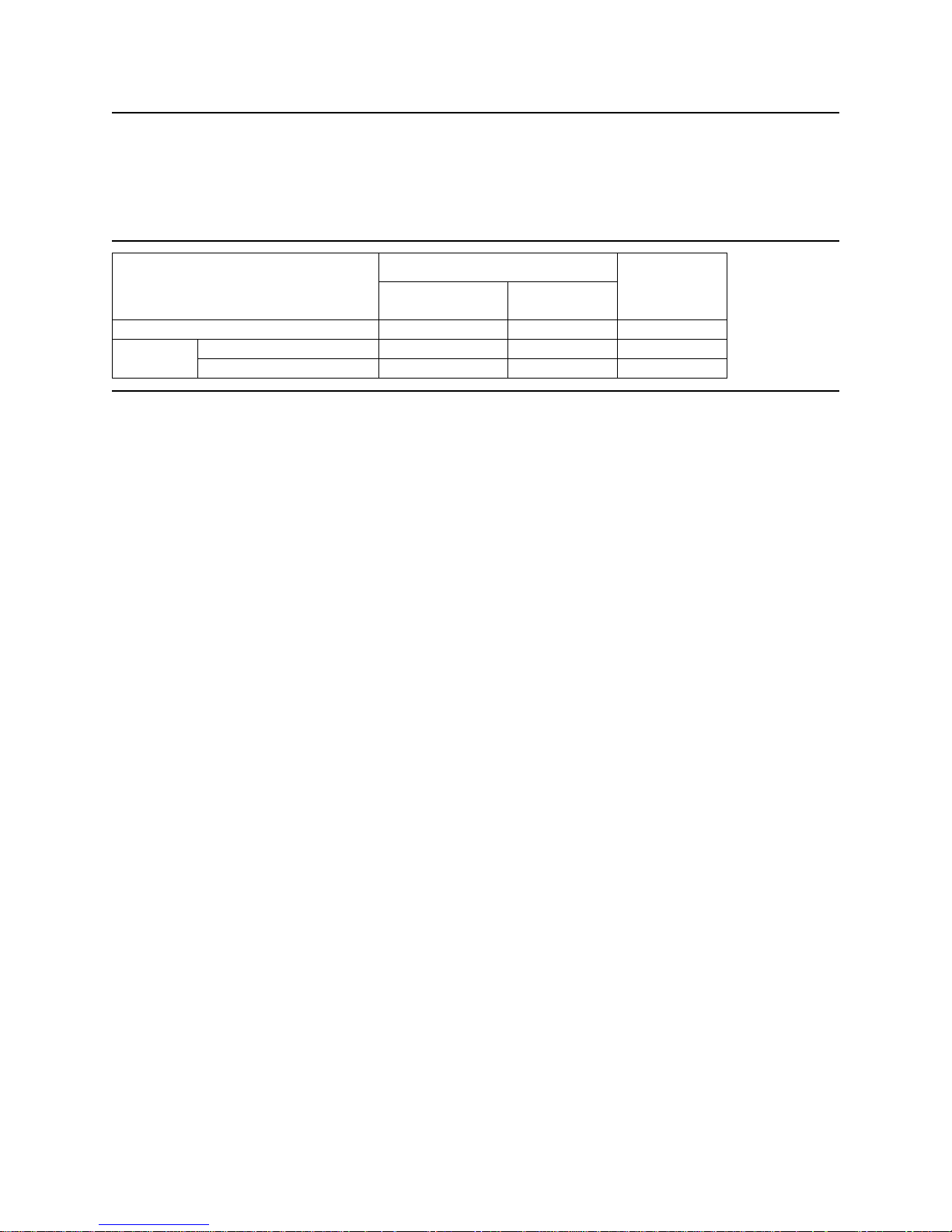
6.9 Acoustics
The upper limit criteria of the octave sound power levels are given in Bels relative to one picowatt and are
shown in the following table. The sound power emission levels are measured in accordance with
ISO 7779.
Typical
Mode
Operating
Figure 67. Sound power levels
Mode definition:
Idle mode. The drive is powered on, disks spinning, track following, unit ready to receive and
respond to interface commands.
Operating mode. Continuous random cylinder selection and seek operation of the actuator with a
dwell time at each cylinder. The seek rate for the drive is to be calculated as shown below:
! Dwell time = 0.5 x 60/RPM
1 and 3 disk
models
2 disk models
Max
3.43.03.1Idle
3.73.43.4Performance seek mode
3.53.13.2Quiet seek mode
! Seek rate = 0.4 / (Average seek time + Dwell time)
Deskstar 120GXP hard disk drive specifications
58
Page 73

6.10 Identification labels
The following labels are affixed to every drive shipped from the drive manufacturing location in accordance
with the appropriate hard disk drive assembly drawing:
• A label containing the IBM logo, the IBM part number, and the statement “Made by IBM Japan Ltd.”
or IBM approved equivalent
• A label containing the drive model number, the manufacturing date code, the formatted capacity,
the place of manufacture, UL/CSA/TUV/CE/C-Tick mark logos
• A bar code label containing the drive serial number
• A label containing the jumper pin description
• A user designed label per agreement
The above labels may be integrated with other labels.
Deskstar 120GXP hard disk drive specifications
59
Page 74

6.11 Safety
6.11.1 UL and CSA standard conformity
The product is qualified per UL 1950 Third Edition and CAN/CSA C22.2 No. 950-M95, Third Edition, for
use in Information Technology Equipment including Electric Business Equipment.
The UL recognition or the CSA certification is maintained for the product life.
The UL and C-UL recognition mark or the CSA monogram for CSA certification appear on the drive.
6.11.2 German Safety Mark
The product is approved by TUV on Test requirement: EN 60 950:1992/A1-4 but the GS mark is not
applicable to internal devices such as this product.
6.11.3 Flammability
The printed circuit boards used in this product are made of material with the UL recognized flammability
rating of V-1 or better. The flammability rating is marked or etched on the board. All other parts not considered electrical components are made of material with the UL recognized flammability rating of V-1 or
better. However, small mechanical parts such as cable ties, washers, screws, and PC board mounts may
be made of material with a UL recognized flammability rating of V-2.
6.11.4 Safe handling
The product is conditioned for safe handling in regards to sharp edges and corners.
6.11.5 Environment
The product does not contain any known or suspected carcinogens.
Environmental controls meet or exceed all applicable government regulations in the country of origin. Safe
chemical usage and manufacturing control are used to protect the environment. An environmental impact
assessment has been done on the manufacturing process used to build the drive, the drive itself and the
disposal of the drive at the end of its life.
Production also meets the requirements of the international treaty on chlorofluorocarbon (CFC) control
known as the United Nations Environment Program Montreal Protocol, and as ratified by the member
nations. Material to be controlled include CFC-11, CFC-12, CFC-113, CFC-114, CFC-115, Halon 1211,
Halon 1301 and Halon 2402. Although not specified by the Protocol, CFC-112 is also controlled. In
addition to the Protocol IBM requires the following:
! that no packaging used for the shipment of the product use controlled CFCs in the manufacturing
process.
! that no manufacturing processes for parts or assemblies include printed circuit boards use con-
trolled CFC materials.
6.11.6 Secondary circuit protection
Spindle/VCM driver module includes 12 V over current protection circuit.
Deskstar 120GXP hard disk drive specifications
60
Page 75

6.12 Electromagnetic compatibility
When installed in a suitable enclosure and exercised with a random accessing routine at maximum data
rate, the drive meets the following worldwide EMC requirements:
! United States Federal Communications Commission (FCC) Rules and Regulations (Class B), Part
15. IBM Corporate Standard C-S 2-0001-026 (A 6 dB buffer shall be maintained on the emission
requirements).
! European Economic Community (EEC) directive number 76/889 related to the control of radio fre-
quency interference and the Verband Deutscher Elektrotechniker (VDE) requirements of Germany
(GOP). IBM National Bulletin NB 2-0001-400, NB 2-0001-401, and NB 2-0001-403.
! Electrostatic Discharge Susceptibility limits for a Class 2 ESD environment specified in IBM
Corporate Standard C-S 2-0001-005.
! Radiated Electromagnetic Susceptibility (RES) as specified in IBM Corporate Standard C-S
2-0001-012.
! Spectrum Management Agency (SMA) EMC requirements of Australia. The SMA has approved two
forms of C-Tick Marking for IBM. IBM National Bulletin NB 2-0001-406
6.12.1 CE Mark
The product is declared to be in conformity with requirements of the following EC directives under the sole
responsibility of IBM United Kingdom Ltd. or Yamato Lab, IBM Japan Ltd:
Council Directive 89/336/EEC on the approximation of laws of the Member States relating to
electromagnetic compatibility.
6.12.2 C-Tick Mark
The product complies with the following Australian EMC standard:
Limits and methods of measurement of radio disturbance characteristics of information technology, AS/NZS 3548 : 1995 Class B.
Deskstar 120GXP hard disk drive specifications
61
Page 76

This page intentionally left blank.
Page 77

Part 2. Interface specification
Deskstar 120GXP hard disk drive specifications
63
Page 78

This page intentionally left blank.
Page 79

7.0 General
This specification describes the host interface of the Deskstar 120GXP hard disk drive.
The interface conforms to the Working Document of Information Technology - AT Attachment with Packet
Interface Extension (ATA/ATAPI-5), Revision 3, dated 29 February 2000, with certain limitations described
in 7.2, “Deviations from standard.”
7.1 Terminology
The Deskstar 120GXP hard disk driveDevice
The system to which the device is attachedHost
7.2 Deviations from standard
The device conforms to the referenced specifications with the following deviations:
Check Power Mode. Check Power Mode command returns FFh to Sector Count Register when the
device is in Idle mode. This command does not support 80h as the return value.
Hard Reset. Hard reset response is not the same as that of power on reset. Refer to Section 9.1,
“Reset Response” on page 73 for details.
Deskstar 120GXP hard disk drive specifications
65
Page 80

This page intentionally left blank.
Page 81

8.0 Registers
FunctionsAddresses
WRITE (DIOW–)READ (DIOR–)DA0DA1DA2CS1–CS0–
Not usedData bus high impedancexxxNN
Control block registers
Not usedData bus high impedancexx0AN
Not usedData bus high impedancex01AN
Device ControlAlternate Status011AN
Not usedDevice Address111AN
Command block registers
DataData000NA
FeaturesError Register100NA
Sector CountSector Count010NA
Sector NumberSector Number110NA
110NA
LBA bits 0–7
1
LBA bits 0–7
1
Cylinder LowCylinder Low001NA
001NA
LBA bits 8–15
1
LBA bits 8–15
1
Cylinder HighCylinder High101NA
101NA
LBA bits 16–23
1
LBA bits 16–23
1
Device/HeadDevice/Head.011NA
011NA
LBA bits 24–27
1
LBA bits 24–27
1
CommandStatus111NA
Invalid addressxxxAA
1
Mapping of registers in LBA mode
A = signal assertedLogic conventions:
N = signal negated
X=maybeAorN
Figure 68. Register Set
Communication to or from the device is through an I/ O Register that routes the input or output data to or
from registers addressed by the signals from the host (CS0–, CS1–, DA2, DA1, DA0, DIOR– and DIOW–).
The Command Block Registers are used for sending commands to the device or posting status from the
device.
The Control Block Registers are used for device control and for posting alternate status.
Deskstar 120GXP hard disk drive specifications
67
Page 82

8.1 Alternate Status Register
Alternate Status Register
01234567
DSC/
DFRDYBSY
SERV
Figure 69. Alternate Status Register
This register contains the same information as the Status Register. The only difference is that reading this
register does not imply interrupt acknowledge or clear a pending interrupt. See 8.13, “Status Register” on
page 72 for the definition of the bits in this register.
ERRIDXCORDBQ
8.2 Command Register
This register contains the command code being sent to the device. Command execution begins immediately after this register is written. The command set is shown in Figure 88 on page 104.
All other registers required for the command must be set up before writing the Command Register.
8.3 Cylinder High Register
This register contains the high order bits of the starting cylinder address for any disk access. At the end of
the command this register is updated to reflect the current cylinder number.
In LBA Mode this register contains Bits 16-23. At the end of the command this register is updated to reflect
the current LBA Bits 16-23.
The cylinder number may range from zero to the number of cylinders minus one.
8.4 Cylinder Low Register
This register contains the low order bits of the starting cylinder address for any disk access. At the end of
the command this register is updated to reflect the current cylinder number.
In LBA Mode this register contains Bits 8-15. At the end of the command this register is updated to reflect
the current LBA Bits 8-15.
The cylinder number may be from zero to the number of cylinders minus one.
Deskstar 120GXP hard disk drive specifications
68
Page 83

8.5 Data Register
This register is used to transfer data blocks between the device data buffer and the host. It is also the
register through which sector information is transferred on a Format Track command and configuration
information is transferred on an Identify Device command.
All data transfers are 16 bits wide, except for ECC byte transfers which are 8 bits wide. Data transfers are
PIO only.
The register contains valid data only when DRQ=1 in the Status Register.
8.6 Device Control Register
Device Control Register
01234567
0–IENSRST1––––
Figure 70. Device Control Register
Bit Definitions
SRST (RST) Software Reset. The device is held reset when RST=1. Setting RST=0 re-enables the
device.
The host must set RST=1 and wait for at least 5 µs before setting RST=0 to ensure that
the device recognizes the reset.
-IEN Interrupt Enable. When -IEN=0 and the device is selected, device interrupts to the host
will be enabled. When -IEN=1 or the device is not selected, device interrupts to the host
will be disabled.
8.7 Drive Address Register
Drive Address Register
01234567
–DS0–DS1–H0–H1–H2–H3–WTGHIZ
Figure 71. Drive Address Register
This register contains the inverted drive select and head select addresses of the currently selected drive.
Bit Definitions
HIZ High Impedance. This bit is not driven and will always be in a high impedance state.
-WTG -Write Gate. This bit is 0 when writing to the disk device is in progress.
-H3,-H2,-H1,-H0 -
-Head Select. These four bits are the 1's complement of the binary coded address of the
currently selected head. -H0 is the least significant.
Deskstar 120GXP hard disk drive specifications
69
Page 84

-DS1 -Drive Select 1. Drive select bit for device 1, active low. DS1=0 when device 1 (slave) is
selected and active.
-DS0 -Drive Select 0. Drive select bit for device 0, active low. DS0=0 when device 0 (master) is
selected and active.
8.8 Device/Head Register
Device/Head Register
01234567
HS0HS1HS2HS3DRV1L1
Figure 72. Device/Head Register
This register contains the device and head numbers.
Bit Definitions
L Binary encoded address mode select. When L=0, addressing is by CHS mode. When
L=1, addressing is by LBA mode.
DRV Device. When DRV=0, device 0 (master) is selected. When DRV=1, device 1 (slave) is
selected.
HS3, HS2, HS1, HS0
Head Select. These four bits indicate binary encoded address of the head. HS0 is the
least significant bit. At command completion these bits are updated to reflect the currently
selected head.
The head number may be from zero to the number of heads minus one.
In LBA mode HS3 through HS0 contain bits 24-27 of the LBA. At command completion
these bits are updated to reflect the current LBA bits 24-27.
8.9 Error Register
Error Register
01234567
AMNFTK0NFABRT0IDNF0UNCCRC
Figure 73. Error Register
This register contains status from the last command executed by the device or a diagnostic code.
At the completion of any command – except Execute Device Diagnostic – the contents of this register are
always valid even if ERR=0 is in the Status Register.
Following a power on, a reset, or completion of an Execute Device Diagnostic command, this register con-
tains a diagnostic code. See Figure 77 on page 74 for the definition.
Deskstar 120GXP hard disk drive specifications
70
Page 85

Bit Definitions
ICRCE
(CRC)
UNC
ABRT
(ABT)
TK0NF
(T0N)
AMNF
(AMN)
Interface CRC Error. CRC=1 indicates a CRC error has occurred on the data bus
during Ultra-DMA transfer.
Uncorrectable Data Error. UNC=1 indicates an uncorrectable data error has been
encountered.
ID Not Found. IDN=1 indicates the ID field of the requested sector could not be found.IDNF (IDN)
Aborted Command. ABT=1 indicates the requested command has been aborted due to
a device status error or an invalid parameter in an output register.
Track 0 Not Found. T0N=1 indicates track 0 was not found during a Recalibrate
command.
Address Mark Not Found. AMN=1 indicates that data address mark has not been
found after finding the correct ID field for the requested sector.
8.10 Features Register
This register is command specific. This is used with the Set Features command, S.M.A.R.T. Function Set
command, and Format Unit command.
8.11 Sector Count Register
This register contains the number of sectors of data requested to be transferred on a read or write
operation between the host and the device. If the value in the register is set to 0, a count of 256 sectors is
specified.
If the register is zero at command completion, the command was successful. If it is not successfully completed, the register contains the number of sectors which need to be transferred in order to complete the
request.
The contents of the register are defined otherwise on some commands. These definitions are given in the
command descriptions.
8.12 Sector Number Register
This register contains the starting sector number for any disk data access for the subsequent command.
The sector number is from one to the maximum number of sectors per track.
In LBA mode this register contains Bits 0-7. At the end of the command this register is updated to reflect
the current LBA Bits 0-7.
Deskstar 120GXP hard disk drive specifications
71
Page 86

8.13 Status Register
Status Register
01234567
DSC/
DFDRDYBSY
SERV
Figure 74. Status Register
This register contains the device status. The contents of this register are updated whenever an error
occurs and at the completion of each command.
If the host reads this register when an interrupt is pending, it is considered to be the interrupt acknowledge. Any pending interrupt is cleared whenever this register is read.
If BSY=1, no other bits in the register are valid.
Bit Definitions
BSY Busy. BSY=1 whenever the device is accessing the registers. The host should not read or
write any registers when BSY=1. If the host reads any register when BSY=1, the contents
of the Status Register will be returned.
DRDY (RDY) Device Ready. RDY=1 indicates that the device is capable of responding to a command.
RDY will be set to zero during power on until the device is ready to accept a command. If
the device detects an error while processing a command, RDY is set to zero until the
Status Register is read by the host, at which time RDY is set back to one.
ERRIDXCORRDRQ
DF Device Fault. DF = 1 indicates that the device has detected a write fault condition. DF is
set to zero after the Status Register is read by the host.
DSC Device Seek Complete. DSC=1 indicates that a seek has completed and the device head
is settled over a track. DSC is set to zero by the device just before a seek begins. When
an error occurs, this bit is not changed until the Status Register is read by the host at
which time the bit again indicates the current seek complete status. When the device
enters into or is in Standby mode or Sleep mode, this bit is set by device in spite of not
spinning up.
SERV (SRV) Service. SRV is set to one when the device is ready to transfer data after it releases the
bus for execution of a DMA Queued command.
DRQ Data Request. DRQ=1 indicates that the device is ready to transfer a word or byte of data
between the host and the device. The host should not write the Command register when
DRQ=1.
CORR (COR)Corrected Data. Always zero.
IDX Index. IDX=1 once per revolution. Because IDX=1 only for a very short time during each
revolution, the host may not see it set to one even if the host is continuously reading the
Status Register. Therefore the host should not attempt to use IDX for timing purposes.
ERR Error. ERR=1 indicates that an error occurred during execution of the previous command.
The Error Register should be read to determine the error type. The device sets ERR=0
when the next command is received from the host.
Deskstar 120GXP hard disk drive specifications
72
Page 87

9.0 General operation
9.1 Reset response
There are three types of resets in ATA:
Power On Reset (POR). The device executes a series of electrical circuitry diagnostics, spins up the
HDA, tests speed and other mechanical parameters, and sets default values.
Hard Reset (Hardware Reset). RESET- signal is negated in ATA Bus. The device resets the
interface circuitry as well as Soft Reset.
Soft Reset (Software Reset). SRST bit in the Device Control Register is set and then is reset. The
device resets the interface circuitry according to the Set Features requirement.
The actions of each reset is shown in the following figure.
Soft ResetHard ResetPOR
OO–Aborting Host interface
(1)(1)–Aborting Device interface
XXOInitialization of hardware
XXOInternal diagnostic
XXOSpinning spindle
OOOInitialization of registers (2)
XOODASP handshake
OOOPDIAG handshake
Reverting programmed parameters to default
! Number of CHS (set by Initialize Device Parameter)
! Multiple mode
! Write Cache
! Read look-ahead
! ECC bytes
(3)(3)O
XXODisable Standby timer
(4)(4)(5)Power mode
O - execute X - not execute
Notes:
(1) Execute after the data in write cache has been written.
(2) Default value on POR is shown in Figure 76 on page 74.
(3) The Set Features command with Feature register = CCh enables the device to revert these para-
meters to the power on defaults.
(4) In the case of Sleep mode the device goes to Standby mode. In other cases the device does not
change current mode.
(5) Idle when Power-Up in Standby feature set is disabled. Standby when Power-Up in Standby
feature set is enabled.
Figure 75. Reset Response Table
Deskstar 120GXP hard disk drive specifications
73
Page 88

9.2 Register initialization
After power on, hard reset, or software reset, the register values are initialized as shown in the figure
below.
Default ValueRegister
Diagnostic CodeError
01hSector Count
01hSector Number
00hCylinder Low
00hCylinder High
A0hDevice/Head
50hStatus
50hAlternate Status
Figure 76. Default Register Values
The meaning of the Error Register diagnostic codes resulting from power on, hard reset, or the Execute
Device Diagnostic command are shown in the figure below.
DescriptionCode
No error detected01h
Formatter device error02h
Sector buffer error03h
ECC circuitry error04h
Controller microprocessor error05h
Device 1 failed8xh
Figure 77. Diagnostic Codes
Deskstar 120GXP hard disk drive specifications
74
Page 89

9.3 Diagnostic and reset considerations
For each Reset and Execute Device Diagnostic the diagnostic is done as follows:
Power On Reset. DASP- is read by Device 0 to determine if Device 1 is present. If Device 1 is
present, Device 0 shall read PDIAG- to determine when it is valid to clear the BSY bit and whether
Device 1 has powered on or reset without error. Otherwise Device 0 clears the BSY bit whenever it is
ready to accept commands. Device 0 may assert DASP- to indicate device activity.
Hard Reset, Soft Reset. If Device 1 is present Device 0 shall read PDIAG- to determine when it is
valid to clear the BSY bit and whether Device 1 has reset without any errors. Otherwise Device 0
shall simply reset and clear the BSY bit. DASP- is asserted by Device 0 (and Device 1 if it is present)
in order to indicate device active.
Execute Device Diagnostic. If Device 1 is present, Device 0 shall read PDIAG- to determine when
it is valid to clear the BSY bit and if Device 1 passed or failed the EXECUTE DEVICE DIAGNOSTIC
command. Otherwise Device 0 shall simply execute its diagnostics and then clear the BSY bit.
DASP- is asserted by Device 0 (and Device 1 if it is present) in order to indicate the device is active.
In all the above cases Power on, RESET-, Soft reset, and the EXECUTE DEVICE DIAGNOSTIC command the Device 0 Error register as shown in the figure below.
Device 1
present?
'x' indicates the appropriate Diagnostic Code for the Power on, RESET–, Soft Reset, or Device Diagnostic
error.
Figure 78. Reset error register values
PDIAG–
Asserted?
Device 0
Passed
Error
Register
01hYesYesYes
0xhNoYesYes
81hYesNoYes
8xhNoNoYes
01hYes(not read)No
0xhNo(not read)No
Deskstar 120GXP hard disk drive specifications
75
Page 90

9.4 Sector Addressing Mode
All addressing of data sectors recorded on the drive media is by a logical sector address. The logical CHS
address for the drive is different from the actual physical CHS location of the data sector on the disk
media.
The drive supports both Logical CHS Addressing Mode and LBA Addressing Mode as the sector addressing mode.
The host system may select either the currently selected CHS translation addressing or LBA addressing
on a command-by-command basis by using the L bit in the DEVICE/HEAD register. So a host system
must set the L bit to 1 if the host uses LBA Addressing mode.
9.4.1 Logical CHS Addressing Mode
The logical CHS addressing is made up of three fields: cylinder number, head number and sector number.
Sectors are numbered from 1 to the maximum value allowed by the current CHS translation mode but
cannot exceed 255(0FFh). Heads are numbered from 0 to the maximum value allowed by the current CHS
translation mode but cannot exceed 15(0Fh). Cylinders are numbered from 0 to the maximum value
allowed by the current CHS translation mode but cannot exceed 65535(0FFFFh).
When the host selects a CHS translation mode using the INITIALIZE DEVICE PARAMETERS command,
the host requests the number of sectors per logical track and the number of heads per logical cylinder.
The device then computes the number of logical cylinders available in requested mode.
The default CHS translation mode is described in the Identify Device Information. The current CHS translation mode is also described in the Identify Device Information.
9.4.2 LBA Addressing Mode
Logical sectors on the device shall be mapped linearly with the first LBA addressed sector (sector 0) being
the same sector as the first logical CHS addressed sector ( cylinder 0, head 0, sector 1). Regardless of
the logical CHS translation mode currently in effect, the LBA address of a given logical sector does not
change. The following formula is always true:
LBA = ((cylinder x heads per cylinder + heads) x sectors per track) + sector – 1
where heads per cylinder and sectors per track are the current translation mode values
On LBA addressing mode the LBA value is set to the following register:
Device/Head <--- LBA bits 27-24
Cylinder High <--- LBA bits 23-16
Cylinder Low <--- LBA bits 15-8
Sector Number <--- LBA bits 7-0
.
Deskstar 120GXP hard disk drive specifications
76
Page 91

9.5 Overlapped and queued feature
Overlap allows devices to perform a bus release so that the other device on the bus may be used. To
perform a bus release the device clears both DRQ and BSY to zero. When selecting the other device
during overlapped operations, the host shall disable interrupts via the nIEN bit on the currently selected
device before writing the Device/Head register to select the other device.
The only commands that may be overlapped are
('00'h)NOP (with 01h subcommand code)
('C7'h)Read DMA Queued
('A2'h)Service
('CC'h)Write DMA Queued
For the READ DMA QUEUED and WRITE DMA QUEUED commands, the device may or may not perform
a bus release. If the device is ready to complete the execution of the command, it may complete the
command immediately. If the device is not ready to complete the execution of the command, the device
may perform a bus release and complete the command via a service request.
Command queuing allows the host to issue concurrent commands to the same device. Only commands
included in the overlapped feature set may be queued. If a queue exists when a non-queued command is
received, the nonqueued command shall be aborted and the commands in the queue shall be discarded.
The ending status shall be ABORT command and the results are indeterminate.
The maximum queue depth supported by a device is indicated in word 73 of Identify Device information.
A queued command shall have a Tag provided by the host in the Sector Count register to uniquely identify
the command. When the device restores register parameters during the execution of the SERVICE
command, this Tag shall be restored so that the host may identify the command for which status is being
presented. If a queued command is issued with a Tag value that is identical to the Tag value for a command already in the queue, the entire queue is aborted including the new command. The ending status is
ABORT command and the results are indeterminate. If any error occurs, the command queue is aborted.
When the device is ready to continue processing a bus released command and BSY and DRQ are both
cleared to zero, the device requests service by setting SERV to one, setting a pending interrupt, and
asserting INTRQ if selected and if nIEN is cleared to zero. SERV shall remain set until all commands
ready for service have been serviced. The pending interrupt shall be cleared and INTRQ negated by a
Status register read or a write to the Command register.
When the device is ready to continue processing a bus released command and BSY or DRQ is set to one
(i.e., the device is processing another command on the bus), the device requests service by setting SERV
to one. SERV shall remain set until all commands ready for service have been serviced. At command
completion of the current command processing (i.e., when both BSY and DRQ are cleared to zero), the
device shall process interrupt pending and INTRQ per the protocol for the command being completed. No
additional interrupt shall occur due to other commands ready for service until after the SERV bit of the
device has been cleared to zero.
When the device receives a new command while queued commands are ready for service, the device
shall execute the new command and process interrupt pending and INTRQ per the protocol for the new
command. If the queued commands ready for service still exist at command completion of this command,
SERV remains set to one but no additional interrupt shall occur due to commands ready for service.
When queuing commands, the host shall disable interrupts via the nIEN bit before writing a new command
to the Command register and may re-enable interrupts after writing the command. When reading status at
command completion of a command, the host shall check the SERV bit since the SERV bit may be set
because the device is ready for service associated with another queued command. The host receives no
additional interrupt to indicate that a queued command is ready for service.
Deskstar 120GXP hard disk drive specifications
77
Page 92

9.6 Power management feature
The power management feature functions permit a host to reduce the power required to operate the drive.
It provides a set of commands and a timer that enables a device to implement low power consumption
modes.
The drive implements the following set of functions:
! Standby timer
! Idle command
! Idle Immediate command
! Sleep command
! Standby command
! Standby Immediate command
9.6.1 Power modes
The lowest power consumption when the device is powered on occurs in Sleep Mode. When in sleep
mode the device requires a reset to be activated.
In Standby Mode the device interface is capable of accepting commands, but as the media may not be
immediately accessible, there is a delay while waiting for the spindle to reach operating speed.
In Idle Mode the device is capable of responding immediately to media access requests.
In Active Mode the device is executing a command or accessing the disk media with the read look- ahead
function or the write cache function.
9.6.2 Power management commands
The Check Power Mode command enables a host to determine if a device is currently in, going into, or
leaving standby mode.
The Idle and Idle Immediate commands move a device to idle mode directly from the active or standby
modes. The idle command also sets the standby timer count and starts the standby timer.
The Standby and Standby Immediate commands move a device to standby mode directly from the active
or idle modes. The standby command also sets the standby timer count.
The Sleep command moves a device to sleep mode. The interface of the device becomes inactive at the
completion of the sleep command. A reset is required to move a device out of sleep mode. When a device
exits sleep mode, it enters Standby mode.
9.6.3 Standby timer
The standby timer provides a method for the device to automatically enter standby mode from either
active or idle mode following a host programmed period of inactivity. If the device is in the active or idle
mode, the device waits for the specified time period and, if no command is received, the device automatically enters the standby mode.
If the value of SECTOR COUNT register on Idle command or Standby command is set to 00h, the standby
timer is disabled.
Deskstar 120GXP hard disk drive specifications
78
Page 93

9.6.4 Interface capability for power modes
Each power mode affects the physical interface as defined in the following table.
RDYBSYMode
Figure 79. Power conditions
Ready (RDY) is not a power condition. A device may post ready at the interface even though the media
may not be accessible.
Interface
active
Media
ActiveYesXXActive
ActiveYes1OIdle
InactiveYes1OStandby
InactiveNoXXSleep
Deskstar 120GXP hard disk drive specifications
79
Page 94

9.7 S.M.A.R.T. function
The intent of Self-Monitoring Analysis and Reporting Technology (S.M.A.R.T) is to protect user data and
prevent unscheduled system downtime that may be caused by predictable degradation and/or fault of the
device. By monitoring and storing critical performance and calibration parameters, S.M.A.R.T devices
employ sophisticated data analysis algorithms to predict the likelihood of near-term degradation or fault
condition. By alerting the host system of a negative reliability status condition, the host system can warn
the user of the impending risk of a data loss and advise the user of appropriate action.
9.7.1 Attributes
Attributes are the specific performance or calibration parameters that are used in analyzing the status of
the device. Attributes are selected by the device manufacturer based on the ability of that attribute to
contribute to the prediction of degrading or faulty conditions for that particular device. The specific set of
attributes being used and the identity of these attributes is vendor specific and proprietary.
9.7.2 Attribute values
Attribute values are used to represent the relative reliability of individual performance or calibration attributes. The valid range of attribute values is from 1 to 253 decimal. Higher attribute values indicate that
the analysis algorithms being used by the device are predicting a lower probability of a degrading or faulty
condition existing. Accordingly, lower attribute values indicate that the analysis algorithms being used by
the device are predicting a higher probability of a degrading or faulty condition.
9.7.3 Attribute thresholds
Each attribute value has a corresponding attribute threshold limit which is used for direct comparison to
the attribute value to indicate the existence of a degrading or faulty condition. The numerical values of the
attribute thresholds are determined by the device manufacturer through design and reliability testing and
analysis. Each attribute threshold represents the lowest limit to which its corresponding attribute value
can be equal while still retaining a positive reliability status. Attribute thresholds are set at the device
manufacturer's factory and cannot be changed in the field. The valid range for attribute thresholds is from
1 through 253 decimals.
9.7.4 Threshold Exceeded Condition
If one or more attribute values, whose Pre-failure bit of their status flag is set, are less than or equal to
their corresponding attribute thresholds, the device reliability status is negative, indicating an impending
degrading or faulty condition.
9.7.5 S.M.A.R.T. commands
The S.M.A.R.T. commands provide access to attribute values, attribute thresholds, and other logging and
reporting information.
9.7.6 Off-line read scanning
The device provides the off-line read scanning feature with reallocation. This is the extension of the offline data collection capability. The device performs the entire read scan with reallocation of the marginal
sectors to prevent loss of user data.
If interrupted by the host during the read scanning, the device services the host command.
9.7.7 Error log
Logging of reported errors is supported. The device provides information on the last five errors that the
device reported as described in the SMART error log sector. The device may also provide additional
Deskstar 120GXP hard disk drive specifications
80
Page 95

vendor specific information on these reported errors. The error log is not disabled when SMART is
disabled. Disabling SMART disables the delivering of error log information via the SMART READ LOG
SECTOR command.
If a device receives a firmware modification, all error log data is discarded and the device error count for
the life of the device is reset to zero.
9.7.8 Self-test
The device provides the self-test features which are initiated by SMART Execute Off-line Immediate
command. The self-test checks the fault of the device, reports the test status in Device Attributes Data,
and stores the test result in the SMART self-test log sector as described in the SMART self-test log data
structure. All SMART attributes are updated accordingly during the execution of self-test.
If interrupted by the host during the self-tests, the device services the host command.
If the device receives a firmware modification, all self-test log data is discarded.
Deskstar 120GXP hard disk drive specifications
81
Page 96

9.8 Security Mode Feature Set
Security Mode Feature Set is a powerful security feature. With a device lock password, a user can prevent
unauthorized access to a hard disk drive even if the device is removed from the computer.
The following commands are supported for this feature:
Security Set Password
Security Unlock
Security Erase Prepare
Security Erase Unit
Security Freeze Lock
Security Disable Password
('F1'h)
('F2'h)
('F3'h)
('F4'h)
('F5'h)
('F6'h)
9.8.1 Security mode
The following security modes are provided:
Device Locked mode The device disables media access commands after power on. Media
access commands are enabled by either a security unlock command or a
security erase unit command.
Device Unlocked mode The device enables all commands. If a password is not set this mode is
entered after power on, otherwise it is entered by a security unlock or a
security erase unit command.
Device Frozen mode The device enables all commands except those which can update the de-
vice lock function, set/change password. The device enters this mode via
a Security Freeze Lock command. It cannot quit this mode until power off.
9.8.2 Security level
The following security levels are provided:
High level security When the device lock function is enabled and the User Password is for-
gotten, the device can be unlocked via a Master Password.
Maximum level security When the device lock function is enabled and the User Password is for-
gotten, only the Master Password with a Security Erase Unit command
can unlock the device. User data is then erased.
9.8.3 Passwords
This function can have the two kinds of passwords described below:
Master Password When the Master Password is set, the device does NOT enable the
Device Lock Function and the device cannot be locked with the Master
Password, but the Master Password can be used for unlocking the device
locked.
Identify Device Information word 92 contains the value of the Master
Password Revision Code set when the Master Password was last
changed. Valid values are 0001h through FFFEh.
User Password The User Password should be given or changed by a system user. When
the User Password is set, the device enables the Device Lock Function
and the device is then locked on next power on reset or hard reset.
Deskstar 120GXP hard disk drive specifications
82
Page 97

The system manufacturer or dealer who intends to enable the device lock function for end-users must set
the master password even if only single level password protection is required.
9.8.4 Operation example
9.8.4.1 Master Password setting
The system manufacturer or dealer can set a new Master Password from default Master Password using
the Security Set Password command without enabling the Device Lock Function.
The Master Password Revision Code is set to FFFEh as shipping default by the drive manufacturer.
9.8.4.2 User Password setting
When a User Password is set, the device will automatically enter lock mode when the device is powered
on the next time.
(Ref.)
< Not setting password >< Setting password >
PORPOR
Set password with user password
Normal operation
Normal operation
Power offPower off
Figure 80. Initial Setting
POR —> Device unlocked modePOR —> Device locked mode
Deskstar 120GXP hard disk drive specifications
83
Page 98

9.8.4.3 Operation from POR after User Password is set
When Device Lock Function is enabled, the device rejects media access command until a Security Unlock
command is successfully completed.
POR
Device Locked mode
Unlock CMD
Password
Match ?
N
Y
Enter Device
Unlock mode
Enter Device Frozen mode
Erase Prepare Media Access Non-media access
Lock function
Normal operation : All commands are available
Freeze Lock command
Normal Operation except Set Password,
Disable Password, Erase Unit, Unlock commands.
(*1) Refer to figure 83 on page 86.
Erase Unit
Password
Match ?
Y
Complete
Erase Unit
Disable
Command (*1) Command (*1)
N
Reject
Complete
Figure 81. Usual Operation
Deskstar 120GXP hard disk drive specifications
84
Page 99

9.8.4.4 User Password Lost
If the User Password is forgotten and High level security is set, the system user cannot access any data.
However the device can be unlocked using the Master Password.
If a system user forgets the User Password and Maximum security level is set, data access is impossible.
However the device can be unlocked using the Security Erase Unit command to unlock the device and
erase all user data with the Master Password.
User Password Lost
Unlock EMD with Master Password
Normal operation
Erase Prepare Command
Erase Unit Command
with Master Password
Normal operation but data lost
Figure 82. Password Lost
LEVEL ? High
Maximum
9.8.4.5 Attempt limit for SECURITY UNLOCK command
The SECURITY UNLOCK command has an attempt limit. The purpose of this attempt limit is to prevent
someone from attempting to unlock the drive by using various passwords multiple times.
The device counts the password mismatch. If the password does not match, the device counts it without
distinguishing the Master password and the User password. If the count reaches 5, EXPIRE bit (bit 4) of
Word 128 in Identify Device information is set and the SECURITY ERASE UNIT command and the
SECURITY UNLOCK command are then aborted until a hard reset or a power off. The count and EXPIRE
bit are cleared after a power-on reset or a hard reset.
Deskstar 120GXP hard disk drive specifications
85
Page 100

9.8.5 Command table
This table shows the response of the device to commands when the Security Mode Feature Set (Device
lock function) is enabled.
Frozen ModeUnlocked ModeLocked ModeCommand
ExecutableExecutableExecutableCheck Power Mode
ExecutableExecutableExecutableExecute Device Diagnostic
ExecutableExecutableCommand aborted Device Configuration Restore
ExecutableExecutableExecutableDevice Configuration Freeze Lock
ExecutableExecutableExecutableDevice Configuration Identify
ExecutableExecutableCommand abortedDevice Configuration Set
ExecutableExecutableCommand abortedFlush Cache
ExecutableExecutableCommand abortedFormat Track
ExecutableExecutableExecutableIdentify Device
ExecutableExecutableExecutableIdle
ExecutableExecutableExecutableIdle Immediate
ExecutableExecutableExecutableInitialize Device Parameters
ExecutableExecutableExecutableNOP
ExecutableExecutableExecutableRead Buffer
ExecutableExecutableCommand abortedRead DMA
ExecutableExecutableCommand abortedRead DMA Queued
ExecutableExecutableCommand abortedRead Long
ExecutableExecutableCommand abortedRead Multiple
ExecutableExecutableExecutableRead Native Max Address
ExecutableExecutableCommand abortedRead Sector(s)
ExecutableExecutableCommand abortedRead Verify Sector(s)
ExecutableExecutableExecutableRecalibrate
Command abortedExecutableCommand abortedSecurity Disable Password
Command abortedExecutableExecutableSecurity Erase Prepare
Command abortedExecutableExecutableSecurity Erase Unit
ExecutableExecutableCommand abortedSecurity Freeze Lock
Command abortedExecutableCommand abortedSecurity Set Password
Command abortedExecutableExecutableSecurity Unlock
ExecutableExecutableExecutableSeek
ExecutableExecutableCommand abortedService
ExecutableExecutableExecutableSet Features
ExecutableExecutableCommand abortedSet Max Address
ExecutableExecutableExecutableSet Multiple Mode
ExecutableExecutableExecutableSleep
ExecutableExecutableExecutableSMART Disable Operations
ExecutableExecutableExecutableSMART Enable/Disable Attributes Autosave
Figure 83. Command table for device lock operation (part 1 of 2)
Deskstar 120GXP hard disk drive specifications
86
 Loading...