

Page 1

MODEL: IBM-3920
2.4GHz DSST CALL WAITING
CALLER ID WIRELESS TELEPHONE
IMPORTANT: To receive Caller ID information on incoming telephone calls, you must
subscribe to the Caller ID service provided by your local telephone company; there is a
fee for this service and it may not be available in all areas.
®
600-0630401-A
INSTALLATION AND OPERATING GUIDE
Page 2

Important Safety Instructions .............2
FCC Regulations ...............................3-4
Battery Cautionary Instructions .........5
IBM-3920 Parts Checklist .....................6
Location of Controls and
Features ...........................................7- 11
Handset ...........................................7-8
Base ..............................................9-10
LCD Display ......................................11
Choosing a Location .........................12
Battery Installation ............................13
Battery Duration ...............................13
When the Battery Needs Charging ...13
When to Purchase a New
Battery Pack .....................................13
Connecting the Phone ......................14
Connect the Base .............................14
Connect the Charging Cradle ...........14
Initialize the Handset to the Base .....14
Wall Mounting .....................................15
Headset and Data Jack ......................16
The Data Jack ...................................16
The Headset Jack.............................16
Belt-Clip ............................................16
Settings ..........................................17-27
Handset Settings ..............................17
Setting the Username .......................18
Changing the Ringer Level ...............18
Changing the Ring Tone ...................19
Setting the Time and Date ...........19-20
Setting the Area Code ......................21
Turning Key Beeps On/Off ................22
Changing the Flash Time .................23
Changing the Pause Time ................24
Changing the Tone/Pulse Mode .......25
Setting the Line in Use Check ............26
Resetting to Factory Defaults ...........27
Basic Displays ....................................28
Basic Operation .............................29-30
Making Calls .....................................29
Receiving Calls ................................29
Putting a Call on Hold .......................30
Using the Monitor ............................30
Additional Options ...........................30
Speed Dialing ...............................31-34
Storing Phone Numbers ...............31-32
Letter Table ........................................32
Making Calls with Speed Dialing .......33
Deleting a Stored Number ................33
Editing a Stored Number ...................34
Name Matching .................................34
Redial .................................................35
Redial the Last Number .....................35
Redial Last 10 Numbers ....................35
Storing Redial Numbers ....................35
Caller ID .........................................36-40
When You Receive a Call .................36
Viewing the Caller ID List ..................36
Caller ID Displays ..............................37
Caller ID with Call Waiting Service ....38
Storing Caller ID Records .................38
Deleting Caller ID Records ...............39
Returning Caller ID Calls ...................40
Message Waiting ................................41
New Call Light ...................................41
Other Features ...................................42
Using the Handset Finder (PAGE) ....42
Out-of-Range Warning .....................42
Care and Maintenance .......................43
Glossary ..............................................44
Troubleshooting ............................45-46
Warranty .........................................47-48
Wall Mount Templates ........................49
Replacement Battery Order Form ....50
This symbol is to alert you to important operating or servicing instructions that may appear in the
user's manual. Always follow basic safety precautions when using this product to reduce the risk of
injury, fire or electrical shock.
When using this product, basic safety precautions should always be followed to reduce the risk of fire, electric shock
and injury to persons, including the following:
1. Read and understand all instructions.
2. Follow all warnings and instructions marked on the product.
3. Use only with class 2 power source DC 9V 300mA (base) and class 2 power source DC 9V 100mA (charging cradle).
4. Unplug this product from the wall outlet before cleaning. Do not use liquid cleaners or aerosol cleaners. Use a damp cloth
for cleaning.
5. Do not use this product near water; for example, near a bathtub, wash bowl, kitchen sink or laundry tub, in a wet basement
or near a swimming pool.
6. Do not place this product on an unstable cart, stand or table. The product may fall, causing serious damage to the product.
7. Slots and openings in the cabinet back or bottom are provided for ventilation. To protect it from overheating, these openings
must not be blocked or covered. The openings should never be blocked by placing the product on the bed, sofa, rug, or other
similar surface.This product should never be placed near or over a radiator or heat register.This product should not be placed
in an enclosed environment unless proper ventilation is provided.
8. Do not allow anything to rest on the power cord. Do not locate this product where the cord will be abused by animals or
persons walking on it.
9. Do not overload wall outlets and extension cords as this can result in risk of fire or electrical shock.
10. Never push objects of any kind into this product through cabinet slots as they may touch dangerous voltage points or short
out parts that could result in a risk of fire or electrical shock. Never spill liquid of any kind on the product.
11. To reduce the risk of electrical shock, do not disassemble this product. Instead take it to a qualified service person when
service or repair work is required. Opening or removing covers may expose you to dangerous voltages or other risks. Incorrect
re-assembly can cause electrical shock when the appliance is subsequently used.
12. Unplug all cords and refer servicing to qualified service personnel under the following conditions:
A. When the power supply cord or plug is damaged or frayed.
B. If liquid has been spilled into the product.
C. If the product has been exposed to rain or water.
D. If the product does not operate normally by following the operating instructions. Adjust only those controls covered in
the operating instructions. Improper adjustment of other controls may result in damage and require work by a qualified
technician to restore the product to normal operation.
13. Avoid using a telephone (other than a cordless type) during an electrical storm. There may be a remote risk of electric shock
from lightning.
14. Do not use a telephone to report a gas leak in the vicinity of the leak.
IF YOUR PRODUCT UTILIZES BATTERIES,THE FOLLOWING ADDITIONAL PRECAUTIONS SHOULD BE OBSERVED:
1. Use only the type and size of batteries specified in the users manual.
2. Do not dispose of the batteries in a fire. The cells may explode.Check with local codes for possible special disposal instructions.
3. Do not open or mutilate the batteries. Released electrolyte is corrosive and may cause damage to the eyes or skin.It may be
toxic if swallowed.
4. Exercise care in handling batteries in order not to short the battery with conducting materials such as rings, bracelets and
keys. The battery or conductor may overheat and cause burns.
5. Do not attempt to recharge the batteries provided with or identified for use with this product. The batteries may leak corrosive
electrolyte or explode.
6. Do not attempt to rejuvenate the batteries provided with or identified for use with this product by heating them.Sudden release
of the battery electrolyte may occur, causing burns or irritation to eyes or skin.
7. When replacing batteries, all batteries should be replaced at the same time. Mixing fresh and discharged batteries could
increase internal cell pressure and rupture the discharged batteries.
8. When inserting the batteries into this product, the proper polarity or direction must be observed. Reverse insertion of batteries
can cause charging, which may result in leakage or explosion.
9. Remove the batteries from this product if the product will not be used for a long period of time (several months or more) since
during this time the batteries could leak, damaging the product.
10. Discard "dead" batteries as soon as possible since they are more likely to leak in a product.
11. Do not store this product, or the batteries provided with or identified for use with this product, in high temperature areas.
12. If your product uses a rechargeable battery, charge the battery(ies) only in accordance with the instructions and limitations
specified in the User’s Manual.
SAVE THESE INSTRUCTIONS
IMPORTANT SAFETY INSTRUCTIONS
2
IBM-3920 TABLE OF CONTENTS
1
Page 3

5. This product is compatible with inductively coupled hearing aids.
Note: This applies only if this product is equipped with a corded or cordless
handset.
6. Programming/testing emergency numbers:
When programming emergency numbers and/or making test calls to emergency
numbers:
A. Remain on the line and briefly explain to the dispatcher the reason for the call
before hanging up.
B. Perform such activities in the off-peak hours, such as early morning or late
evening.
INTERFERENCE INFORMATION: PART 15 OF FCC RULES
Some telephone equipment generates and uses radio frequency energy that, if not
properly installed, may cause interference to radio and television reception.
This unit has been tested and found to comply with the limits for a Class B computing
device in accordance with the specifications in subpart J of Part 15 of the FCC rules.
These specifications are designed to provide reasonable protection against such
interference in a residential installation. However, there is no guarantee that
interference will not occur in a particular installation.
If this equipment does cause interference to radio or television reception when it’s in
use, the user is encouraged to try to correct the interference by one or more of the
following measures:
A. Where it can be done safely, reorient the radio or TV receiving antenna.
B. To the extent possible, relocate the television, radio or other receiver with respect
to the telephone equipment.
C. If your telephone product runs on AC power, plug your product into an AC outlet
that’s not on the same circuit as the one used by the radio or television.
4
FCC REGULATIONS
Modifying or tampering with the telephone's internal components can cause a malfunction
and might invalidate the telephone's warranty and void your FCC authorization to operate
it. If the trouble is harming the telephone lines, the telephone company might ask you to
disconnect the telephone until you have resolved the problem.
As it complies with Part 68 of the FCC rules, your unit has been registered with the FCC.
The FCC requires us to provide you with the following information:
1. Connection and use with the nationwide telephone network:
The FCC requires that you connect to a nationwide telephone network through a
modular telephone outlet which is Part 68 compliant. This equipment may not be used
on coin service provided by the telephone company. Connection to party lines is
subject to state tariffs. Check with your local telephone company.
2. Notification to the telephone company:
FCC rules require that upon request you provide the following information to the phone
company:
A. The line (telephone number) to which you will connect the telephone equipment,
and
B. The FCC Registration Number and Ringer Equivalence Number (REN). These
numbers are found on the back or bottom of your telephone equipment. The REN
is useful to determine the quantity of devices you may connect to your telephone
line and still have all of those devices ring when your telephone number is called.
In most, but not all areas, the sum of all RENs should be five or less. To determine the number of devices permitted in your area, contact your local telephone
company.
3. Repair instructions:
If it is determined that your telephone equipment is malfunctioning, the FCC
requires that it not be used and be unplugged from the modular outlet until the
problem has been corrected. Repairs to this telephone equipment can be made only
by the manufacturer or its authorized agents, or by others who may be authorized
by the FCC. Unauthorized repairs void registration and warranty.
4. Rights of the telephone company:
If your product is causing harm to the telephone network, the telephone company
may temporarily discontinue your service. If possible, they will notify you in
advance. But if advance notice isn’t practical, you will be notified as soon as
possible. You will be given the opportunity to correct the problem, and you will be
informed of your right to file a complaint with the FCC.Your telephone company may
make changes in its facilities, equipment, operations or procedures that could affect
the proper functioning of your telephone equipment. If such changes are planned,
you will be notified in advance.
3
FCC REGULATIONS
Page 4
BATTERIES: CAUTION
To reduce the risk of fire or injury to persons, read and follow these instructions:
• For the cordless handset, use only 3.6V 600mAh Nickel Metal Hydride (Ni-MH)
cordless telephone battery pack IBM-ENB1 (included).
• Do not dispose of the batteries in a fire. The cells may explode. Check with local codes
for possible special disposal instructions.
• Do not open or mutilate the batteries. Released electrolyte is corrosive and may cause
damage to the eyes or skin. It may be toxic if swallowed.
• Exercise care in handling batteries in order not to short the battery with conducting
materials such as rings, bracelets, and keys. The battery or conductor may overheat
and cause burns.
• Do not attempt to rejuvenate the batteries identified for use with this product by
heating them. Sudden release of the battery electrolyte may occur causing burns or
irritation to the eyes or skin.
• When inserting batteries into this product, the proper polarity or direction must be
observed. Reverse insertion of batteries can cause charging, and that may result in
leakage or explosion.
• Remove the batteries from this product if the product will not be used for a long period
of time (several months or more) since during this time the battery could leak in the
product.
• Do not store this product, or the batteries provided with or identified for use with this
product, in high temperature areas. Batteries that are stored in a freezer or refrigerator
for the purpose of extending shelf life should be protected from condensation during
storage and defrosting.
Batteries should be stabilized at room temperature prior to use after cold storage.
5
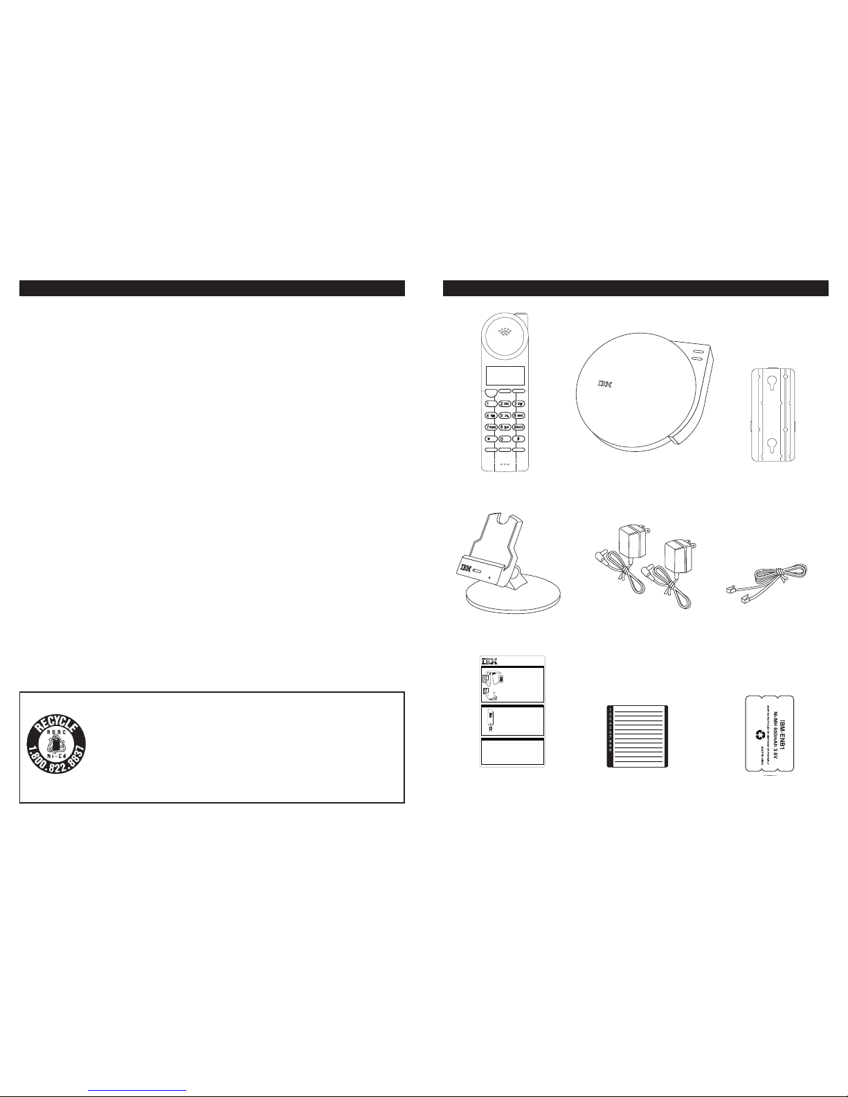
BATTERY CAUTIONARY INSTRUCTIONS IBM-3920 PARTS CHECKLIST
6
Talk
Flash
Monitor
Redial
Jan 01 Monday
USERNAME 12:28AM
MEM CID
In Use
Page/Find
1. Handset 2. Base 3. Base Wall Mount Plate
7. Quick start card
+
—
QUICK START GUIDE
IBM-3920
Connect the base
1. Connect the telephone line cord to the "LINE"
jack and to a telephone outlet.
2. Connect the AC power adapter to the 9V DC
jack and to an AC outlet.
Connect the charging cradle
1. Connect the other AC power adapter to an AC
outlet and into the plug in the bottom of the
charging cradle.
Register the handset to the base
1.Push and hold the P on the base and the CHkey
on the handset at the same time.The unit will give a
confirmation tone.
SETTING UP THE PHONE
Line
DC 9V IN
Data
!
1. Slide the battery pack up into the compartment at the
bottom of thehandset. Make sure that the “- +” on
the battery faces the front of the handset and that the
“- +”end of the battery is inserted first.
2.
Snap the battery compartment cover into place and
place the handset on the charging cradle.
3. Once you have installed the battery pack and placed
the handset on the cradle you will hear a tone
indicating thehandset has connected with the
charging contacts and will successfully charge.
INSTALLTHE BATTERY
1. Pick up the handset from the charging cradle.
2.
Press T.The display willshow
"CONNECTING".
Once the IBM-3920has
acquired a line the display will showthe channel that it is using (eg.
CHANNEL 50).Wait until you hear a dial tone.
3. Dial the number you wish to dial.
4 When you are finished talking, press the T key or place the handset back
into the cradle to end the call.
MAKING CALLS
Insert
battery
with this
label
facing
handset
back
9. Ni-MH battery pack
8. Memory Card
4. Charging Cradle
#
*
5. (2) AC power adapters
6. 7-foot line cord
The EPA certified RBRC®Battery Recycling Seal on the nickel-metalhydride
(Ni-MH) battery indicates TT Systems LLC is voluntarily participating in an
industry program to collect and recycle these batteries at the end of their use-
ful life, when taken out of service in the United States or Canada. The RBRC
®
program provides a convenient alternative to placing used Ni-MH batteries into
the trash or the municipal waste stream, which may be illegal in your area.
Please call 1-800-8-BATTERY for information on Ni-MH battery recycling and
disposal bans/restrictions in your area. TT Systems LLC’s involvement in this
program is part of our commitment to preserving our environment and conserving our natural resources.
Page 5

LOCATION OF CONTROLS AND FEATURES
Handset
7
Talk
Flash
Monitor
Redial
Jan 01 Monday
USERNAME 12:28AM
MEM CID
Headset Jack
4-Line LCD
Display
Multi-Function
Keys
Microphone
Redial Key
Dial Pad
New Call Light
Talk Key
Temporary Tone
Key
Flash Key
Mute Key
Monitor Key
Up/Down
Key
Talk T
The T key is used to access the telephone line or end a call. The T key also
operates as a multi-function key when accessing different telephone modes (OK,
Yes, and Call). See the fourth line of the display above the key for its current
use.
Multi-Function Keys B
The two B keys are used to access additional features of the telephone,
depending on what mode the phone is in (MEM, CID, DEL, <--, Exit, Opts, Mute,
Unmute, Hold, New, and No). See the fourth line of the display above the
individual key for its current use.
Up/Down Key
The key lets you scroll through menu options and adjust the handset volume.
Dial Pad
Numeric keys are used in the conventional manner for dialing.
Monitor Key m
The m key enables you to monitor a phone call hands-free by amplifying
the speaker. Does not disconnect when the handset is placed in the cradle.
Flash Key F
The F key is used to access telephone company services like call waiting.
Redial Key R
Pressing the R key will automatically redial the last number dialed. It is also
used to program an adjustable measured pause into a dialing sequence stored in
a memory location.
Mute Key
Use the Mute key to temporarily mute the handset microphone. While in standby
mode, press and hold the
Mute key to access handset setting programming.
Temporary Tone Key *
If the phone is set to pulse dialing in the handset settings, pressing * causes
subsequent digits to be dialed out using tone until the line is put back on hook.
Headset Jack
Allows using a headset for hands-free convenience.
LOCATION OF CONTROLS AND FEATURES
8
Page 6

Line
DC 9V IN
Data
!
Base
Page/Find Button - Use the P to page the person holding the handset. It
also helps to find the handset when it is out of the cradle.
In Use LED - Lights green when the handset is being used.
9
LOCATION OF CONTROLS AND FEATURES
In Use
Page/Find
Page/Find Button
In Use LED
Data Jack
Used to connect a computer or fax machine.
Line Jack
Used to connect the base to the telephone line.
LOCATION OF CONTROLS AND FEATURES
Base Back View
10
Data
Jack
Line
Jack
Charge LED
Lights green when the handset is properly making contact with the charge
terminals.
Charge LED
Page 7

LCD
Display
Name Character Field
Displays caller’s name when viewing Caller ID. Sometimes displays other status
information when the phone is idle.
Number Field
The number field will display numbers when dialing, viewing Caller ID, and when
viewing the phone book. Displays the username and time when idle.
Time/Date Field
Shows the date and time of Caller ID calls or current date & day of the week
when the phone is idle.
Function Field
Shows the functions currently available using the multi-function keys below the
display.
Priority, New and Repeat Calls
A P icon will display on the right side of the Time/Date field when the caller ID
entry is one that has been flagged as a priority call. An N icon will display in
that location when the caller ID entry has not been reviewed (new). An
R icon
will display in the same location if the same Caller ID information has been
received more than one time.
2:36AM 1/01 N
555-555-1212
SMITH JOHN
Call Opts Exit
11
LOCATION OF CONTROLS AND FEATURES
Do the following:
• Choose the best location
• Connect the phone
• Choose the dialing mode
Where you place the phone affects the reception quality of the handset:
• Away from another cordless telephone
• Place the base near an AC electrical outlet and near telephone line jack
• Place the base away from metal walls and metal file cabinets
CAUTION: The cordless telephone operates at a frequency that may cause
interference to nearby TVs and VCRs; the base phone should not be placed
near, or on top of a TV or VCR. If interference is experienced, moving the
cordless telephone farther away from the TV or VCR will often reduce or
eliminate the interference.
Note: While the 2.4GHZ frequency is inherently clearer, we suggest that you do
not use this phone within 20 feet of a working microwave. The microwave produces frequencies in this range which may cause interference.
CHOOSING A LOCATION
Away from noise sources such as a
window by a street with heavy traffic
Away from VCRs and TV sets and
other electronic equipment
Away from heat sources, such as
radiators, air ducts and sunlight
Away from a microwave oven
Away from excessive
moisture, extremely low
temperatures, dust,
mechanical vibration or
shock
Away from a
personal computer
Near a central
location and on a
level surface
12
Name Character Field
Number Field
Time/Date Field
Function Field
Page 8

To install the cordless handset Ni-MH battery pack:
1. Slide the battery pack up into the compartment at the
bottom of the handset. Make sure that the label with two
arrows faces the back of the handset and that the “
- +”
end of the battery is inserted first.
2. Snap the battery compartment cover into place.
3. Place the handset on the charging cradle.
4. Once you have installed the battery pack and placed the
handset on the cradle. The display will show
"CHARGING."
5. IMPORTANT: Charge the battery pack for at least 12
hours before using the handset the first time.
6. The Charge LED on the charging cradle will light when
the handset is properly making contact with the charge
terminals.
Battery Duration
A fully charged battery lasts for approximately:
• 5 hours when you use the handset continuously (talk
time).
• 7 days when the handset is not in use (standby).
When the Battery Needs Charging
• The phone will beep.
• The display will show "BATTERY LOW" and the
Battery Low Icon.
When to Purchase a New Battery Pack
If the battery lasts only a few minutes even after a full charge, the usable life of the
battery has expired and needs to be replaced. Contact TT Systems LLC customer
support center at
1-800-955-1009 or on the Internet at www.ttsystems.com.
Connect the base
1. Connect the telephone
line cord to the
"LINE"
jack and to a telephone
outlet.
2. Connect the larger of the
two AC power adapters
to the 9V DC jack and to
an AC outlet.
Tip: If your telephone outlet
is not a standard
RJ11/RJ14 wall jack,
contact your telephone
company for assistance.
Connect the charging cradle
1. Connect the other AC power adapter
to an AC outlet and into the plug in
the bottom of the charging cradle.
Initialize the handset to the base
1. Once phone is fully connected and
the handset is placed in the charging
cradle, the phone will automatically
register to the base, selecting one of
over 60,000 security codes.
2. If for some reason it is necessary to reinitialize the handset, simultaneously
push and hold the
P key on the base and the F key on the handset
for five seconds, or until "REGISTER" appears on the display.
Note: Use only the supplied AC power adapters. Connect the AC power
adapters to a continuous power supply. Place both the base and
charging cradle close to the AC outlet so that you can plug in the AC
power adapter easily.
13
CONNECTING THE PHONE
Line
DC 9V IN
Data
!
14
Jan 01 Monday
USERNAME 12:28AM
BATTERY LOW
MEM CID
Insert
battery
with this
label
facing
handset
back
BATTERY INSTALLATION
Battery Low Icon
Page 9

The base unit and the charging cradle may be installed onto two screws (one
pair included) fastened into the wall. When installing screws into plasterboard
walls, use wall anchors (not included) to ensure that the screws remain secure.
Insert the screws into the wall, leaving 3/16" of each screw extending out from
the wall. See the wall mount templates on page 49 to properly space the
screws in the wall for mounting. The IBM-3920 is not compatible with mounting
on a wall mount telephone jack.
Handset/Cradle Wall Mounting Instructions:
1. Remove the handset from the charging cradle.
2. Adjust the charging cradle to the wall mount
position.
3. Plug the AC adapter into the jack in base of the
cradle and run the cable down through the cable
channel.
4. Slip the cradle onto the wall, lining up the wall
mounting holes over the screws. Slide the cradle
down so it is firmly in place.
5. Return the handset to the charging cradle.
6. Plug the other end of the AC adapter into the AC outlet.
Base Wall Mounting Instructions:
1. Place the bottom mounting tab on the end of the base wall
mounting plate into the lower attaching bracket on the back of
the base. Lock the plate in place with the side brackets.
2. Plug the supplied 7-foot telephone cord into the
"LINE" jack on the telephone.
3. Connect the telephone line cord to the wall jack.
4. Insert the AC adapter into the
9V DC jack on the
back of the base.
5. Slip the telephone base onto the wall, lining up the
wall mounting holes over the screws. Slide the
telephone base down so it is firmly in place.
6. Plug the other end of the AC adapter into the AC outlet.
The Data Jack
The jack located on the back of the
base labeled
"DATA" is a
convenience jack. It is useful for
connecting a fax machine or
modem when there is no
telephone jack available for that
device.
The Headset Jack
The headset jack is located on the right side
of the handset and is a standard 2.5mm plug.
Simply plug the headset into the jack and the
headset will be active.
Note: When the headset is plugged into the
telephone, the microphone and
earpiece on the handset are not active.
Belt-Clip
The belt-clip is integrated into the handset of the IBM-3920. To
utilize the clip, simply push down on the top of the clip until it
locks into place.
15
WALL MO UNTING
16
HEADSET AND DATA JACK
Data Jack
Headset Jack
Belt-clip
Line Data
Talk
1
2
ABC
3
DEF
4
5
JKL
6
MNO
GHI
7
8
TUV
9
WXYZ
PQRS
2:24PM 12/15
888-555-1212
JOHN SMITH
Call Opts Exit
Page 10

Handset Settings
You can change the setting on the handset in the
programming menu.
The settings that can be changed in the programming menu
are:
• Username Change the eight character name that is
displayed when the phone is idle.
• Ringer Level Change the volume of the ringer, either
High, Low, or Off.
• Ring Tone Change the way the ringer sounds on the
handset.
• Time and Date Change the time and date.
• Area Codes Allows you to set your home area code, and
local area codes if you have 10-digit dialing, for Caller ID callback. You can
have as many as six local area codes.
• Key Beeps Allows you to either enable the phone beep each time a key is
pressed or disable it.
• Flash Time Allows you to adjust the Flash pause time to accommodate the
phone service in your area.
• Pause Time Allows you to adjust the number of seconds that a pause lasts
when programming your speed dial numbers.
• Tone/Pulse Mode Allows you to select the dialing mode, either Tone or Pulse.
• Line In Use Chk When on, prompts you with “Line In Use Interrupt?” if the
phone line is already being used by another extension.
• Factory Default Resets all the handset settings, including the speed dial
directory, back to the factory defaults.
Note: At any time during options programming you can quit and the settings
that you have selected will be saved. Quit the options menu by pressing
B/Exit or let the menu programming time out by not pressing any
key for 15 seconds.
17
Setting the Username
1. Press and hold the Mute key on the left side of the
handset to enter the programming menu.
2. Press
T/OK.
3. Use the dial pad to enter the username (see “Letter
Ta bl e ” on page 32), up to eight characters.
4. Press
T/OK.
5. Press
B/Exit to return to the idle screen.
Changing the Ringer Level
1. Press and hold the Mute key on the left side of the
handset to enter the programming menu.
2. Press
to go to the Ringer Level programming option.
3. Press
T/OK.
4. Press
or to select between High, Low, and Off.
5. Press
T/OK.
6. Press
B/Exit to return to the idle screen.
SETTINGSSETTINGS
18
>Username
Ringer Level
Ring Tone
OK Exit
>Username
Ringer Level
Ring Tone
OK Exit
Enter Username
OK Exit
Ringer Level
Low
OK Exit
>Ring Tone
Time and Date
Area Code
OK Exit
>Ringer Level
Ring Tone
Time and Date
OK Exit
>Ringer Level
Ring Tone
Time and Date
OK Exit
Talk
1
2
3
ABC
DEF
4
5
6
GHI
JKL
MNO
7
8
9
PQRS
TUV
Flash
Redial
Monitor
WXYZ
*
0
#
Mute
Jan 01 Monday
USERNAME 12:28AM
MEM CID
s
t
Mute
Mute Key
Up/Down Key
Talk
1
2
3
ABC
DEF
4
5
6
GHI
JKL
MNO
7
8
9
PQRS
TUV
Flash
Redial
Monitor
WXYZ
*
0
#
Mute
Jan 01 Monday
USERNAME 12:28AM
MEM CID
Page 11

4. Press or to select the month.
5. Press
T/OK.
6. Press
or to select the date.
7. Press
T/OK.
8. Press
or to select the day of the week.
9. Press
T/OK.
10. Press
or to select the hour.
11. Press
T/OK.
12. Press
or to select the minute.
13. Press
T/OK.
14. Press
or to select between AM or PM.
15. Press
T/OK.
16. Press
B/Exit to return to the idle screen.
Note: At any time during time and date programming you can press B/<--
to go back to the previous setting.
20
SETTINGS
Changing the Ring Tone
1. Press and hold the Mute key on the left side of the
handset to enter the programming menu.
2. Press
until you reach the Ring Tone programming
option
3. Press
T/OK.
4. Press
or to select between Ring Tone #1, #2, #3,
and #4.
5. Press
T/OK.
6. Press
B/Exit to return to the idle screen.
Setting the Time and Date
1. Press and hold the Mute key on the left side of the
handset to enter the programming menu.
2. Press
until you reach the Time and Date
programming option.
3. Press
T/OK.
SETTINGS
>Username
Ringer Level
Ring Tone
OK Exit
>Time and Date
Area Code
Key Beeps
OK Exit
Ring Tone #1
OK Exit
>Ring Tone
Time and Date
Area Code
OK Exit
>Username
Ringer Level
Ring Tone
OK Exit
>Time and Date
Area Code
Key Beeps
OK Exit
YYY
Jan 01 Monday
Jan
OK Exit
YY
Apr 01 Monday
01
OK <-- Exit
YYYYYY
Jan 01 Monday
Monday
OK <-- Exit
YY
12:01AM
12
OK <-- Exit
YY
10:01AM
01
OK <-- Exit
YY
12:01AM
AM
OK <-- Exit
>Area Code
Key Beeps
Flash Time
OK Exit
19
Talk
1
2
3
ABC
DEF
4
5
6
GHI
JKL
MNO
7
8
9
PQRS
TUV
Flash
Redial
Monitor
WXYZ
*
0
#
Mute
Jan 01 Monday
USERNAME 12:28AM
MEM CID
Talk
1
2
3
ABC
DEF
4
5
6
GHI
JKL
MNO
7
8
9
PQRS
TUV
Flash
Redial
Monitor
WXYZ
*
0
#
Mute
Jan 01 Monday
USERNAME 12:28AM
MEM CID
Talk
1
2
3
ABC
DEF
4
5
6
GHI
JKL
MNO
7
8
9
PQRS
TUV
Flash
Redial
Monitor
WXYZ
*
0
#
Mute
Jan 01 Monday
USERNAME 12:28AM
MEM CID
Page 12

Turning Key Beeps On/Off
1. Press and hold the Mute key on the left side of the
handset to enter the programming menu.
2. Press
until you reach the Key Beeps programming
option.
3. Press
T/OK.
4. Press
or to toggle between Enable and Disable.
5. Press
T/OK.
6. Press
B/Exit to return to the idle screen.
Talk
1
2
3
ABC
DEF
4
5
6
GHI
JKL
MNO
7
8
9
PQRS
TUV
Flash
Redial
Monitor
WXYZ
*
0
#
Mute
Jan 01 Monday
USERNAME 12:28AM
MEM CID
SETTINGS
Setting the Area Code
1. Press and hold the Mute key on the left side of the
handset to enter the programming menu.
2. Press
until you reach the Area Code programming
option.
3. Press
T/OK.
4. If you only use 7 digits to dial locally (555-1212), use
the dial pad to enter your 3-digit home area code and
then press
T/OK. You may now press B/Exit
to return to the idle screen.
5. If you use 10-digit dialing in your area (555-555-1212),
press
to enter the first local area code, skipping the
home area code programming.
6. Use the dial pad to enter a 3-digit local area code.
7. Press
to enter the next local area code. Repeat the
same process for all the other local area codes. You
can program up to 8 area codes, but you do not have
to program all of them.
8. When you are done entering area codes, press
T/OK.
9. Press
B/Exit to return to the idle screen.
SETTINGS
22
>Username
Ringer Level
Ring Tone
OK Exit
Home Area Code
OK Exit
Area Code #1
OK Exit
>Key Beeps
Flash Time
Pause Time
OK Exit
>Area Code
Key Beeps
Flash Time
OK Exit
>Username
Ringer Level
Ring Tone
OK Exit
>Key Beeps
Flash Time
Pause Time
OK Exit
Key Beeps
Enable
OK Exit
>Flash Time
Pause Time
Tone/Pulse Mode
OK Exit
21
Talk
1
2
3
ABC
DEF
4
5
6
GHI
JKL
MNO
7
8
9
PQRS
TUV
Flash
Redial
Monitor
WXYZ
*
0
#
Mute
Jan 01 Monday
USERNAME 12:28AM
MEM CID
Page 13

Changing the Pause Time
1. Press and hold the Mute key on the left side of the
handset to enter the programming menu.
2. Press
until you reach the Pause Time programming
option.
3. Press
T/OK.
4. Press
or to select between 01-10 seconds.
5. Press
T/OK.
6. Press
B/Exit to return to the idle screen.
SETTINGS
24
Changing the Flash Time
1. Press and hold the Mute key on the left side of the
handset to enter the programming menu.
2. Press
until you reach the Flash Time programming
option.
3. Press
T/OK.
4. Press
or to select between 700, 660, 620, 600,
580, 400, 270, or 100 ms.
5. Press
T/OK.
6. Press
B/Exit to return to the idle screen.
Note: The standard and default flash time setting is 600msec. This is the
setting you should use to access standard telephone services such as
call waiting. This setting is adjustable to allow for PBX and other special
uses.
SETTINGS
23
Talk
1
2
3
ABC
DEF
4
5
6
GHI
JKL
MNO
7
8
9
PQRS
TUV
Flash
Redial
Monitor
WXYZ
*
0
#
Mute
Jan 01 Monday
USERNAME 12:28AM
MEM CID
Talk
1
2
3
ABC
DEF
4
5
6
GHI
JKL
MNO
7
8
9
PQRS
TUV
Flash
Redial
Monitor
WXYZ
*
0
#
Mute
Jan 01 Monday
USERNAME 12:28AM
MEM CID
>Username
Ringer Level
Ring Tone
OK Exit
>Flash Time
Pause Time
Tone/Pulse Mode
OK Exit
Flash Time
600 ms
OK Exit
>Pause Time
Tone/Pulse Mode
Line In Use Chk
OK Exit
>Username
Ringer Level
Ring Tone
OK Exit
>Pause Time
Tone/Pulse Mode
Line In Use Chk
OK Exit
Pause Time
04 Seconds
OK Exit
>Tone/Pulse Mode
Line In Use Chk
Factory Default
OK Exit
Page 14

Setting the Line In Use Check
1. Press and hold the Mute key on the left side of the
handset to enter the programming menu.
2. Press
until you reach the Line In Use Chk
programming option.
3. Press
T/OK.
4. Press
or to toggle between Enable and Disable.
5. Press
T/OK.
6. Press
B/Exit to return to the idle screen.
SETTINGS
26
Changing the Tone/Pulse Mode
1. Press and hold the Mute key on the left side of the
handset to enter the programming menu.
2. Press
until you reach the Tone/Pulse mode
programming option.
3. Press
T/OK.
4. Press
or to toggle between Tone or Pulse.
5. Press
T/OK.
6. Press
B/Exit to return to the idle screen.
Tip: If you are unsure of the proper dialing mode, make a trial
call with the dial mode setting to TONE MODE. If the call
connects, leave the setting as is; otherwise, set to PULSE
MODE.
SETTINGS
25
>Username
Ringer Level
Ring Tone
OK Exit
>Line In Use Chk
Factory Default
OK Exit
Line In Use Chk
Enable
OK Exit
>Factory Default
OK Exit
Talk
1
2
3
ABC
DEF
4
5
6
GHI
JKL
MNO
7
8
9
PQRS
TUV
Flash
Redial
Monitor
WXYZ
*
0
#
Mute
Jan 01 Monday
USERNAME 12:28AM
MEM CID
Talk
1
2
3
ABC
DEF
4
5
6
GHI
JKL
MNO
7
8
9
PQRS
TUV
Flash
Redial
Monitor
WXYZ
*
0
#
Mute
Jan 01 Monday
USERNAME 12:28AM
MEM CID
>Username
Ringer Level
Ring Tone
OK Exit
>Tone/Pulse Mode
Line In Use Chk
Factory Default
OK Exit
Tone/Pulse Mode
Tone
OK Exit
>Line In Use Chk
Factory Default
OK Exit
Page 15

Handset Idle
Line Ringing with New Call
Line Ringing with Priority Call
Line Ringing with Repeat Call
Charging
Line on Hold
Call Timer
New CID Received
Volume Control
00:20
Volume=3
End Hold Mute
Jan 01 Monday
USERNAME 12:28AM
03 New Calls
MEM CID
00:20
End Hold Mute
00:40
Line On Hold
MEM CID
Jan 01 Monday
USERNAME 12:28AM
CHARGING
Priority Call
555-555-1212
JOHN SMITH
Reject
New Call
555-555-1212
JOHN SMITH
Reject
Jan 01 Monday
USERNAME 12:28AM
MEM CID
Resetting to Factory Defaults
1. Press and hold the Mute key on the left side of the
handset to enter the programming menu.
2. Press
until you reach the Factory Default
programming option.
3. Press
T/OK.
4. Press
T/Yes if you wish to set all the previous
settings, as well as speed dial settings, back to the
Factory Default. Press
B/No to exit without
resetting.
5. Press
B/Exit to return to the idle screen.
Note: A factory default master reset will completely delete all speed dial entries
and caller ID memories, as well as return all handset settings back to the
factory defaults.
SETTINGS
27
BASIC DISPLAYS
28
>Username
Ringer Level
Ring Tone
OK Exit
>Factory Default
OK Exit
Factory Default
Master Reset?
Yes No
>User Name
Ringer Level
Ring Tone
OK Exit
Talk
1
2
3
ABC
DEF
4
5
6
GHI
JKL
MNO
7
8
9
PQRS
TUV
Flash
Redial
Monitor
WXYZ
*
0
#
Mute
Jan 01 Monday
USERNAME 12:28AM
MEM CID
Repeat Call
555-555-1212
JOHN SMITH
Reject
Page 16

Making Calls
1. Pick up the handset from the cradle.
2. Press
T. Wait until you hear a dial tone.
3. Dial the number you wish to dial.
4. After a few seconds of the line being active the display
will begin the call timer.
5. When you are finished talking, press the
T key or
place the handset back into the cradle to end the call.
Note: The IN USE light on the base will illuminate when
the line is active.
Receiving Calls
When you hear the phone ring:
1. The handset LCD will display "Reject" on the bottom
line. After the first ring, Caller ID information is
displayed if you are subscribed to that service from a
telephone company.
2. Press
B/Reject at any time after the phone
begins to ring. This will immediately mute the ringer,
but the call will continue normally, allowing it to store
Caller ID information and reach voice mail or some
other answering device.
3. If the handset is in the cradle, answer the phone by lifting the handset from the cradle. The handset will turn
on. There is no need to push the
T key if the unit is
in the cradle when the call comes in.
4. If the handset is off the cradle, push
T to answer.
5. When you are finished talking, push the
T key or
place the handset back into the cradle to end the call.
BASIC OPERATION
29
Putting a Call on Hold
1. During a phone conversation, press the B/HOLD
key.
2. Press
T to pick up the line on hold.
Note: When a call is placed on hold, it is possible to
access the speed dial and caller ID directories
(view-only) to reference the phone number
information.
Note: The phone will remind you if the call has been on
hold longer than 10 minutes by ringing once every
minute starting at 10 minutes. After a call is on
hold for 15 minutes, the call will be disconnected.
Using the Monitor
The monitor feature is designed to allow you to listen to your telephone call without having to hold a handset up to your ear. There are many reasons to use this
feature, such as if you are on hold and are waiting for the other party to talk to
you again but want your hands free to do something else while you listen.
There are two ways to use the monitor feature:
• Press the m button and then dial out normally. You are free to place the
phone in the charging cradle without being disconnected. The phone will
automatically use monitor mode until either
m is pressed or the handset
is lifted from the cradle.
• Press the m button while the phone is already off-hook. The phone
enters monitor mode and can be placed into the cradle without disconnecting
the phone call. The phone will stay in monitor mode until either
m is
pressed or the handset is lifted from the cradle.
Additional Options
BASIC OPERATION
30
To: Do This:
Adjust the volume in the earpiece Press during a call until the desired volume level is reached.
Switch to temporary tone dialing Press the * key after the phone is in use. The phone will
remain in tone dialing mode for the duration of the call.
Receive a call waiting call Press
F to go to the new caller.
Press
F again to go back to the original caller.
New Call
555-555-1212
JOHN SMITH
Reject
Talk
1
2
3
ABC
DEF
4
5
6
GHI
JKL
MNO
7
8
9
PQRS
TUV
Flash
Redial
Monitor
WXYZ
*
0
#
Mute
Jan 01 Monday
USERNAME 12:28AM
MEM CID
Talk
1
2
3
ABC
DEF
4
5
6
GHI
JKL
MNO
7
8
9
PQRS
TUV
Flash
Redial
Monitor
WXYZ
*
0
#
Mute
Jan 01 Monday
USERNAME 12:28AM
MEM CID
Talk
1
2
3
ABC
DEF
4
5
6
GHI
JKL
MNO
7
8
9
PQRS
TUV
Flash
Redial
Monitor
WXYZ
*
0
#
Mute
Jan 01 Monday
USERNAME 12:28AM
MEM CID
00:20
End Hold Mute
Page 17

Note: If you select a one-touch entry that is already occupied, the current one
will overwrite the old one and the previous entry will only be accessible
from the directory.
9. Press T/OK.
8. The display will show “
Entry Stored...” and you will be returned to the idle
display.
Letter Table
Note: At any time that you enter something incorrectly, pressing the
B/DEL key will delete the current entry or go to a previous entry if
the current one is blank.
Note: You can store a F into a phone number, such as when you would
want to use phone company provided conference calling services and
automatically conference two phone numbers together.
Note: If there are no memory locations left in the speed dial directory the
IBM-3920 will display
"PHONEBOOK FULL." You must delete other
speed dial records to add any more.
Note: The same telephone number can be stored in multiple locations, if
desired.
SPEED DIALING
32
The IBM-3920 will store up to 99 speed dial numbers, up to 12 of which can be
programmed for one-touch dialing.
Storing Phone Numbers
1. With the handset in the idle state, press the memory
key
B/MEM.
2. Press
B/Opts, select “New Entry,” and press
T/OK.
3. Dial the number you wish to store (up to 32 digits) and
press
T/OK. To add a pause, press the R key.
4. Enter the name you wish to store (up to 16 characters)
using the dial pad to enter the letters. See the letter
table for how to program the letters using the dial pad.
When entering letters, if you pause for more than a
second or press a new key, the letter fields will move to
the next space. To add a blank space between words
push
1.
Example: For JOHN SMITH dial this sequence:
5.
Press
T/OK.
6. Use the
key to select if the phone number is a priority number.
7. Press
T/OK.
8. If you would like this number to be one of the 12 onetouch numbers, use the dial pad to enter the location
(0-9, *, or #). If you do not want to make this a onetouch number, leave this entry blank.
SPEED DIALING
31
>New Entry
Edit Entry
Delete Entry
OK Exit
5 666 44 66 1 7777 6 444 8 44
J O H N space S M I T H
>Priority On
Priority Off
OK EXIT
Select One Touch
Key
OK DEL EXIT
Key 1st 2nd 3rd 4th 5th 6th 7th 8th 9th
press press press press press press press press press
1 Space 1 Space 1 Space 1 Space 1 Space
2ABC2 ABC2A
3DEF3DEF3D
4GHI4GHI4G
5JKL5JKL5J
6MNO6MNO 6M
7P Q R S 7 P Q R S
8TUV 8TUV8 T
9W X Y Z 9 W X Y Z
0 “ 0-.,:‘ ?!
**/()&@*/(
##########
Talk
1
2
3
ABC
DEF
4
5
6
GHI
JKL
MNO
7
8
9
PQRS
TUV
Flash
Redial
Monitor
WXYZ
*
0
#
Mute
Jan 01 Monday
USERNAME 12:28AM
MEM CID
Page 18

Making Calls With Speed Dialing
One-Touch Dialing
1. To make a call using one-touch dialing, press and hold the dial pad key that
the number is stored under (0-9, *, #). The IBM-3920 will dial the stored
number.
2. When you are finished talking, press the
T key or place the handset back
into the cradle to end the call.
Note: Be sure to check that the line is not in use by another extension.
Dialing from the Directory
1. To access the speed dial directory press B/MEM.
2. Numbers are stored in the phone book in alphabetical
order. Locate the number you wish to dial using
.
3. Push
T. The number is then dialed.
4. When you are finished talking, press the
T key or
place the handset back into the cradle to end the call.
Deleting a Stored Number
1. Press B/MEM.
2. Locate the number you wish to delete using
.
3. Press
B/Opts. The MEM options menu will be
displayed.
4. Use the
key to select “Delete Entry.”
5. Press
T/OK.
6. Press
T/Yes to delete the entry.
7. When you are finished press
B/Exit.
SPEED DIALING
33
Editing a Stored Number
1. Press B/MEM.
2. Locate the number you wish to edit using
.
3. Press
B/Opts. The MEM options menu will be
displayed.
4. Use the
key to select “Edit Entry.”
5. Press
T/OK.
6. The phone will go through the same process as storing
a number, only with the information already entered.
Use the
B/DEL key to delete incorrect
information. Enter new information normally.
Name Matching
If you have stored names and numbers in the speed dial directory and you
receive a Caller ID call with a number that matches a number in the speed dial
directory the name that is stored will be displayed with the Caller ID number.
SPEED DIALING
34
>New Entry
Edit Entry
Delete Entry
OK Exit
New Entry
>Edit Entry
Delete Entry
OK Exit
Delete Directory
Are You Sure?
Yes No
>New Entry
Edit Entry
Delete Entry
OK Exit
Talk
1
2
3
ABC
DEF
4
5
6
GHI
JKL
MNO
7
8
9
PQRS
TUV
Flash
Redial
Monitor
WXYZ
*
0
#
Mute
Jan 01 Monday
USERNAME 12:28AM
MEM CID
Talk
1
2
3
ABC
DEF
4
5
6
GHI
JKL
MNO
7
8
9
PQRS
TUV
Flash
Redial
Monitor
WXYZ
*
0
#
Mute
Jan 01 Monday
USERNAME 12:28AM
MEM CID
Talk
1
2
3
ABC
DEF
4
5
6
GHI
JKL
MNO
7
8
9
PQRS
TUV
Flash
Redial
Monitor
WXYZ
*
0
#
Mute
Jan 01 Monday
USERNAME 12:28AM
MEM CID
Page 19

Redial the Last Number
1. While the phone is on-hook, press R. The
display will show "Redial #10" and the most recent
number dialed on the phone (up to 32 digits).
2. Press
T/Call to dial the displayed number.
3. Press
B/Exit if you wish to leave redial without
calling.
Redial Last 10 Numbers
1. While the phone is on-hook, press R. The display will show "Redial
#10" and the most recent number dialed.
2. Use the
keys to scroll through the last ten
numbers dialed on the phone. Pressing
when
viewing redial #10, or
when viewing #1, will return
you to the idle screen.
3. Press
T/Call when you wish to dial the displayed number.
4. Press
B/Exit if you wish to leave redial without calling.
Storing Redial Numbers
1. While the phone is on-hook, press R. The
display will show "Redial #10" and the most recent
number dialed.
2. Use the
keys to scroll through the last ten
numbers dialed on the phone to the one you wish to
store.
3. Press
B/MEM to store the displayed number into
the speed dial directory. The process for saving the
number is similar to storing any number into speed dial
(see “Storing Phone Numbers” on page 31).
4. Press
B/Exit if you wish to leave redial without
calling or storing.
REDIAL
35
Caller ID allows the caller's name and phone number to be shown on the display
before you answer the call. In order to use this feature you must first subscribe
to Caller ID name and number service with your telephone company.
When You Receive a Call
1. When the telephone rings, the caller's name and
phone number appears on the display.
2. The new Caller ID record includes the name and number of the caller and the
time and date the record is received. The New Call light will flash to indicate
that you have a new Caller ID call stored in memory.
Note: When the Caller ID information is received, it is stored in memory so that
this information can be recalled for later use. Up to 99 Caller ID calls can
be stored.
Viewing the Caller ID List
This phone automatically stores the last 99 calls received. If a
call is received from the same number more than once on the
same day, no new entry is made, but the repeat call icon (
R)
will display on the entry.
1. With the handset idle press
B/CID.
2. The number of New calls received and the Total
number of calls received is displayed.
3. To scroll through the calls, use the
key. The
will go through the calls from the last call received to
the first. The
will allow you to view the calls from the
first call received to the last. Between the first and last
call the display will show the total number of calls.
4. Press
B/Exit to finish.
CALLER ID
36
New Call
555-555-1212
JOHN SMITH
Reject
2:36AM 1/01 R
555-1212
JOHN SMITH
Call Opts Exit
02 New Calls
28 Total Calls
Exit
Redial #10
555-1212
Call MEM Exit
Redial #1
555-2983
Call MEM Exit
Talk
1
2
3
ABC
DEF
4
5
6
GHI
JKL
MNO
7
8
9
PQRS
TUV
Flash
Redial
Monitor
WXYZ
*
0
#
Mute
Jan 01 Monday
USERNAME 12:28AM
MEM CID
Talk
1
2
3
ABC
DEF
4
5
6
GHI
JKL
MNO
7
8
9
PQRS
TUV
Flash
Redial
Monitor
WXYZ
*
0
#
Mute
Jan 01 Monday
USERNAME 12:28AM
MEM CID
Talk
1
2
3
ABC
DEF
4
5
6
GHI
JKL
MNO
7
8
9
PQRS
TUV
Flash
Redial
Monitor
WXYZ
*
0
#
Mute
Jan 01 Monday
USERNAME 12:28AM
MEM CID
Page 20

Caller ID Displays
When viewing a caller ID record, the name and number, time
and date of the call, and whether the call is New, Repeated,
or Priority are all displayed.
This display is shown when number only Caller ID service is
received.
"No Caller ID Available" will be displayed when Caller ID
information is not available.This call was made from a
telephone company that does not offer Caller ID services
(including international calls).
"Blocked Call" will be shown when a call is received from a
blocked number. For privacy reasons, some states allow
callers the option to prevent their telephone data from being
displayed on the other party's Caller ID display.
Display shows when the Caller ID information was received
incorrectly or only part of the data was received.
Note: When an error is received, none of the data from this
call is saved in memory.
Display shows when a voice mail message has been received
and is stored by message waiting service provided by the
phone company.
This is shown when
B/CID is first pressed and between
the first and last call when viewing the Caller ID list.
This is displayed when
B/CID is pressed and there is no
Caller ID data stored. The phone will return to the idle screen
after 3 seconds.
No New Calls
00 Total Calls
02 New Calls
28 Total Calls
Exit
Jan 01 Monday
USERNAME 12:28AM
Message Waiting
MEM CID
ERROR
2:36AM 1/01
Blocked Call
Opts Exit
2:36AM 1/01
No Caller ID
Available
Opts Exit
2:36AM 1/01
555-1212
Call Opts Exit
2:36AM 1/01 N
555-555-1212
SMITH JOHN
Call Opts Exit
CALLER ID
37
Caller ID with Call Waiting Service
In order to use the "Call Waiting Caller ID" service you must subscribe to a
telephone company that offers Caller ID service combined with "call waiting"
service.
When a new call comes in while you are talking, you will hear a notification beep
from the handset and the volume is momentarily muted. The new caller's name
and phone number, if available, appears on the display.
1. When you receive a "call waiting" call and you want to
connect the call, press
F. The active call will be
placed on hold and the new call will be active.
2. Press
F to alternate between calls.
3. Press
T or place the handset back on the cradle to end the call.
Note: If pressing F does not work, it is possible you need to change your
flash time settings. See “Changing the Flash Time” on page 23 for more
information.
Storing Caller ID Records
1. Press B/CID.
2. Use the
to scroll to the call record you wish to
store.
3. Press
B/Opts. The display will show the CID
options menu.
4. To save the record, use the
key to highlight “Save
in PhoneBk
.”
5. Press
T/OK.
6. The display will show “Entry Stored...” The number is
stored in the speed dial directory and after 3 seconds
the screen will return to the idle display.
7. To edit the entry, you must follow the instructions on
page 34, “Editing a Stored Number.”
38
CALLER ID
2:36AM 1/01 N
555-555-1212
SMITH JOHN
Call Opts Exit
>Erase Call
Save in PhoneBk
Erase All Calls
OK Exit
Talk
1
2
3
ABC
DEF
4
5
6
GHI
JKL
MNO
7
8
9
PQRS
TUV
Flash
Redial
Monitor
WXYZ
*
0
#
Mute
Jan 01 Monday
USERNAME 12:28AM
MEM CID
Page 21

39
Deleting Caller ID Records
When viewing the Caller ID information you can delete a single call record or all
the call records.
To Delete a Single Record
1. Press B/CID
2. Use to scroll to the call record you wish to delete.
3. Press
B/Opts. The CID options menu is
displayed.
4. Use the
key to highlight “Erase Call.”
5. Press
T/OK. The record is erased and the next entry
is displayed.
6. Press
B/Exit to finish.
To Delete All Records
1. Press B/CID
2. Press once to display any call record.
3. Press
B/Opts. The CID options menu is
displayed.
4. Use the
key to highlight “Erase All Calls.”
5. Press
T/OK.
6. To delete the record press
T/Yes . The display will
momentarily show “All Caller ID Erased!!” and then
return to the idle display.
CALLER ID
40
Returning Caller ID Calls
You can return calls by using the Caller ID callback feature.
1. Press
B/CID.
2. Use the
to scroll to the call record you
wish to call back.
3. Press
T/Call. The
display will show "Call this
nbr?"
5. Press T/Call again to dial out the displayed
number.
If the number displayed is not correct (needing 7, 10, 11 digits), do the following
before you dial:
6. Press
B/Edit to toggle among 7, 10, 11 digit
numbers to be dialed out.
7. Press
T/Call to dial the current number displayed.
8. Press
B/Exit to cancel dialing.
9. When you are finished talking, press the
T key or
place the handset back into the cradle to end the call.
Tip: If you set up your home area code and local area codes
in the handset setup mode, you will not have to adjust
the number between 7, 10 or 11 digit dialing (see
Setting the Area Code on page 20 for setup
information).
CALLER ID
Talk
Flash
Monitor
Redial
Jan 01 Monday
USERNAME 12:28AM
MEM CID
Call this nbr?
555-1212
JOHN SMITH
Call Edit Exit
Call this nbr?
1-555-555-1212
JOHN SMITH
Call Edit Exit
Call this nbr?
555-555-1212
JOHN SMITH
Call Edit Exit
Call this nbr?
555-1212
JOHN SMITH
Call Edit Exit
Press B/Edit
Press B/Edit
When you are ready to
dial the number, press
T. The number
displayed will dial out.
Talk/Call Key
Multi-Function
Keys
key
>Erase Call
Save in PhoneBk
Erase All Calls
OK Exit
>Erase Call
Save in PhoneBk
Erase All Calls
OK Exit
>Erase All Calls
OK Exit
Erase All Calls
Are You Sure?
Yes No
Talk
1
2
3
ABC
DEF
4
5
6
GHI
JKL
MNO
7
8
9
PQRS
TUV
Flash
Redial
Monitor
WXYZ
*
0
#
Mute
Jan 01 Monday
USERNAME 12:28AM
MEM CID
Talk
1
2
3
ABC
DEF
4
5
6
GHI
JKL
MNO
7
8
9
PQRS
TUV
Flash
Redial
Monitor
WXYZ
*
0
#
Mute
Jan 01 Monday
USERNAME 12:28AM
MEM CID
Page 22

Using the Handset Finder (PAGE)
1. Press P on the base. If the handset is within range, the handset will
beep for 20 seconds.
2. Press any key on the handset to stop the page/find feature.
Out-of-Range Warning
If you venture too far from the base, the handset will beep and the display will
show “OUT OF RANGE.” Reverse your direction to re-establish connection
with the base or the call will be dropped. When the base detects that the
handset has been out of range for 15 continuous seconds it will release the
engaged line.
Note: When the base loses power, the handset will also beep and display
“OUT OF RANGE.” If this indication occurs when the phone is not in
use, make sure the base is being properly supplied with power.
If you subscribe to voice mail from the telephone
company and if there are voice messages that
have been left in your voice mailbox, the display
will show
"MESSAGE WAITING.”
Note: This function requires voice mail subscription from the local telephone
company. Furthermore, the local phone company must provide a type of
voice mail signaling called "FSK.” Not all telephone companies have the
visual message waiting feature available. Please contact your local
telephone company to check if this is available in your area.
Tip: If you wish to delete the "Message Waiting" message, delete all the Caller ID
messages (see "Deleting Caller ID Records" on page 39).
New Call Light
When you receive new Caller ID or voice mail message, the New Call light will
flash accordingly.
• For Caller ID, the New Call light will flash
quickly to indicate that you have a new Caller
ID call stored in memory.
• When you have a voice message waiting the
New Call light will flash at a slow rate.
MESSAGE WAITING
41 42
OTHER FEATURES
Jan 01 Monday
USERNAME 12:28AM
Message Waiting
MEM CID
New Call Light
Page 23

Your IBM-3920 telephone has been designed to give years of trouble-free
service. It is a sensitive electronic instrument. To assure its longevity, please
read the following maintenance instructions.
1. Keep the IBM-3920 away from heat as high temperatures can shorten the life
of the electrical components and distort or melt its plastic parts.
2. The IBM-3920 should be kept free of dust and moisture. If it gets wet, wipe it
dry immediately. Liquids can contain minerals that can corrode electronic
circuits.
3. Handle your IBM-3920 gently and carefully. Dropping it can cause serious
damage to circuitry, or the plastic case, which may result in malfunction.
4. Do not use any type of chemical or any abrasive powder to clean the
cabinet. Use only mild detergents on a soft, damp cloth to clean the
IBM-3920 telephone.
5. The IBM-3920 has built-in surge protection circuits that meet or exceed FCC
requirements. However, an incident such as a lightning strike at or near the
telephone lines could cause serious damage.
6. If the IBM-3920 is installed in an area with frequent or severe electrical
storms, it is suggested that the telephone be disconnected during these
storms or that additional surge suppression equipment be added to the
installation.
7. In the case of trouble with the telephone, do not attempt to repair the
telephone yourself. It is the responsibility of users requiring service to report
the need for service to our Service Department. They will make the
necessary arrangements for repair or replacement.
8. If you should have any questions about the operation of your IBM-3920
telephone, please call our Service Department at
1-800-955-1009 between
the hours of 9:00 A.M. and 9:00 P.M. Eastern time Monday - Friday. Or you
may contact TT Systems LLC for technical assistance via our Internet Web
site at
www.ttsystems.com or e-mail at tech@ttsystems.com.
9. Please register your product online at
www.ttsystems.com/CustomerSupport/RegOnline.asp.
43
CARE AND MAINTENANCE
44
GLOSSARY
.
.
.
Page 24

Can't receive or make phone calls.
• Check to be sure the phone is set to the correct type of service, either Tone
or Pulse.
Phone says “Out of Range” but I’m right next to the base.
• Make sure the base is being supplied power. The handset will display “Out of
Range” any time it can’t find the base, including when the base is not powered.
4645
No dial tone/phone will not dial out.
• Check that the AC power adapters are plugged into working power outlets.
• Check all telephone cord connections or try another wall jack.
• Make sure the battery is inserted correctly.
• Make sure the handset and base are registered to each other. When they
are not registered together, the handset cannot connect to the phone line to
dial out. See the instructions on page 14, “Initialize the handset to the base.”
Can’t hear the ring signal.
• Check the ringer volume controls; at the lowest level the ring may not be heard.
While on a call, you hear another call on the line or experience radio
frequency interference.
• Switch channels to a clear channel.
• Check the wiring for bad connections.
• Do not use this phone within 20 feet of a working microwave. Microwaves
produce frequencies in this range which may cause interference. This
interference is normal for all 2.4GHz phones and should not be considered a
product defect.
The caller’s name and/or phone number does not appear on the display.
• Make sure you have subscribed to Caller ID service (from local telephone
company).
• Caller ID service may not work when the phone is connected to a Private
Branch Exchange (PBX).
• The call is coming from an area not supplying caller ID data.
"Out of Area"
will appear on the display.
• The caller has requested that their phone number be suppressed from Caller
ID service.
"Blocked Call" or "No Caller ID Available" will appear on the
display.
• You answered the call before Caller ID data was displayed, which usually
occurs after the second ring.
New Call/Message Waiting Indicator doesn’t work properly.
• Make sure you have subscribed to voice mail compatible with "FSK" type
signaling (check with your local phone company). If your voice mail product
from the local phone company does not support "FSK" signaling, you may
use this feature as a New Call Indicator only.
TROUBLESHOOTING
TROUBLESHOOTING
Page 25

48
47
Circumstances may arise where, because of a default on TT Systems LLC's part or other liability, you are entitled to recover damages from TT Systems LLC. In each such instance, regardless of the basis on which you are entitled to claim damages from TT Systems LLC (including
fundamental breach, negligence, misrepresentation, or other contract or tort claim), TT Systems
LLC is only liable for: 1. Damages for bodily injury (including death) and damage to real property and tangible personal property; and 2. The amount of any other actual direct damages or loss,
up to the greater of $500 or the price paid for this product.
UNDER NO CIRCUMSTANCES IS TT SYSTEMS LLC OR IBM LIABLE FOR ANY OF THE
FOLLOWING: (1) THIRD-PARTY CLAIMS AGAINST YOU FOR LOSSES OR DAMAGES
(OTHER THAN THOSE UNDER THE FIRST ITEM LISTED ABOVE); (2) LOSS OF, OR
DAMAGE TO, YOUR RECORDS OR DATA; OR (3) SPECIAL, INCIDENTAL OR INDIRECT
DAMAGES OR FOR ANY ECONOMIC CONSEQUENTIAL DAMAGES (INCLUDING LOST
PROFITS OR SAVINGS), EVEN IF TT SYSTEMS LLC OR IBM ARE INFORMED OF THEIR
POSSIBILITY. SOME JURISDICTIONS DO NOT ALLOW THE EXCLUSION OR LIMITATION
OF INCIDENTAL OR CONSEQUENTIAL DAMAGES, SO THE ABOVE EXCLUSION OR
LIMITATION MAY NOT APPLY TO YOU.
TT Systems LLC reserves the right to make changes in the design of the IBM-3920 and to make
additions or improvements to the IBM-3920 without incurring any obligation to modify any IBM3920 previously sold.
WARRANTY
Statement of limited warranty: TT Systems LLC warrants that for a period of one year from the
date of purchase that this product 1) is free from defects in materials and workmanship and 2)
conforms to its specifications. If this product does not function as warranted during the warranty
period, TT Systems LLC, at its option, will either replace this product with one that is functionally equivalent or will refund your purchase price. These are your exclusive remedies under this
warranty. Please call 1-800-955-1009 for warranty service.
This product is distributed and sold by TT Systems LLC, 7 Odell Plaza, Yonkers, New York 10701,
the official licensee for this product. IBM, the IBM logo trademarks and the IBM trade dress are
owned by International Business Machines Corporation and are used under a license from IBM.
IBM does not manufacture this product and provides no warranty or support for this product.
Please contact TT Systems LLC at
1-800-955-1009 for all questions/comments and service or
support related to this product.
TT Systems LLC warrants that the IBM-3920 sold by TT Systems LLC within the continental limits of the United States, Hawaii and Alaska, are free from defects in materials and workmanship
under normal use and service for 1 year. This warranty is applicable only to the original purchaser of the IBM-3920, when accompanied by a sales receipt stating the date of purchase and
name of the company from which purchased. This warranty is in lieu of and excludes all other
warranties, expressed or implied, including any implied warranty of merchantability or fitness,
and of any other obligation on the part of TT Systems LLC.
If the IBM-3920 shall prove to be defective, then TT Systems LLC shall either replace, repair or
refund the purchase price of the IBM-3920 at its discretion as follows: at no cost to the original
purchaser except shipping charges, within 90 days of the date of purchase.
From 91 days to 365 days, you may return the IBM-3920 to TT Systems LLC at the following
address:
TT Systems LLC, 4 Executive Plaza,Yonkers, New York 10701. Shipping charges
are at the customer’s expense. Please include a copy of your sales receipt and a check or
money order made out to TT Systems LLC for the amount of $14.50 to cover shipping and
handling.
This warranty gives you specific legal rights, and you may also have other rights which vary from
state to state. Some states do not allow limitations on how long an implied warranty lasts and/or
do not allow the exclusions or limitations of incidental or consequential damages, so the above
limitations or exclusions may not apply to you. There is no informal dispute settlement
mechanism available. This warranty will be voided by misuse, improper physical environment,
accident, or improper maintenance by you.
THIS WARRANTY REPLACES ALL OTHER WARRANTIES OR CONDITIONS, EXPRESS OR
IMPLIED, INCLUDING, BUT NOT LIMITED TO, THE IMPLIED WARRANTIES OR CONDITIONS
OF MERCHANTABILITY AND FITNESS FOR A PARTICULAR PURPOSE. THESE
WARRANTIES GIVE YOU SPECIFIC LEGAL RIGHTS AND YOU MAY ALSO HAVE OTHER
RIGHTS WHICH VARY FROM JURISDICTION TO JURISDICTION. SOME JURISDICTIONS
DO NOT ALLOW THE EXCLUSION OR LIMITATION OF EXPRESS OR IMPLIED
WARRANTIES, SO THE ABOVE EXCLUSION OR LIMITATION MAY NOT APPLY TO YOU. IN
THAT EVENT, SUCH WARRANTIES ARE LIMITED IN DURATION TO THE WARRANTY
PERIOD. NO WARRANTIES APPLY AFTER THAT PERIOD.
WARRANTY
Page 26

SAFETY INFORMATION FOR IBM-3920
Your cordless telephone contains a low power transmitter. When the Push-to Talk (PTT)
button is pushed it sends out radio frequency (RF) signals. This device is authorized to
operate at a duty factor not to exceed 50%. In August 1996, the Federal
Communications Commission (FCC) adopted RF exposure guidelines with safety levels
for hand -held wireless devices.
CAUTION: To maintain compliance with the FCC’ s RF exposure guidelines, hold
the transmitter and antenna at least 0.5 inches (1.25 centimeters) from your face with
the antenna pointed up and away from the face. If you wear the handset on your body
while using the headset accessory, use only the manufacturers supplied belt clip for this
product and ensure that the antenna is at least 1 inches (2.5 centimeters) from your
body when transmitting.
Use only the supplied antenna. Unauthorized antennas, modifications, or attachments
could damage the transmitter and may violate FCC regulations.
Page 27

REPLACEMENT BATTERY ORDER FORM
50
WALL MOUNTING TEMPLATES
49
TT SYSTEMS LLC
7 Odell Plaza
Yonkers, NY 10701
To order a replacement battery pack for the
IBM-3920 cordless telephone, please mail
this order form to the IBM licensee for this
product.
Please enclose a check or money order
made out to
TT SYSTEM LLC for the
respective amount. Shipping and handling
is included in the price.
Please ship order to:
Name:______________________________
Company:___________________________
Address:____________________________
___________________________________
City:____________State:____Zip:________
_
Ni-MH Battery Packs are $16.95 each
TT SYSTEMS LLC
7 Odell Plaza
Yonkers, NY 10701
(This is your mailing label)
From:
To :
___________________________________
___________________________________
___________________________________
___________________________________
___________________________________
__________________
Expansion
Anchor
#6 or #8 Pan Head
Self Tapping Screw
Screws needed for
wall mounting:
Base Template Charging Cradle
Template
3 5/16”
2 3/4”
 Loading...