

Page 1

IBM Systems
Quick start guide for i5 520, 525, and 515 (9405-520,
9406-520, 9406-525, and 9407-515)
Page 2

1
This Quick start guide contains an abbreviated set of setup instructions designed to help you quickly unpack
and set up a standard system. Users unfamiliar with this IBM hardware should use the fully detailed, setup
instructions that you can find in the IBM Systems Hardware Information Center. For details about how to
access the information center, see task 11 .Finish your system setup
Before you begin
The exclamation mark surrounded by a gray triangle denotes caution. A CAUTION notice
indicates the presence of a hazard that has the potential of causing moderate or minor
personal injury. Before doing a step that contains a caution icon, read and understand the
caution statement that accompanies it.
Rack-mounted devices are not to be used as a shelf or workspace. Do not place any
object on top of rack-mounted devices.
Use safe practices when lifting.
32-55 kg (70.5-121.2 lbs)
CAUTION: The weight of this part or unit is between 32 and 55 kg (70.5 and 121.2 lb). It
takes three persons to safely lift this part or unit. (C010)
Tools needed (Rack installation only)
Flat-blade screwdriver
Page 3

2
1
2
2
Inventory
2.1
2.2
Complete an inventory of the external parts.
Locate the kitting report (inventory list) in the bag that contains the information center
CD (SK3T-8159). Make sure you received all of the parts that you ordered. Your order
information should be located in an envelope adhered to the outside of your system box.
You can also obtain order information from your marketing representative or IBM
Business Partner.
If you have incorrect, missing, or damaged parts, contact any of the following resources:
Your IBM reseller
IBM Rochester manufacturing automated information line at 1-800-300-8751
(United States only)
Directory of worldwide contacts at www.ibm.com/planetwide.
Select your location to view the service and support contact information.
If you are not installing your server into a rack, skip to task 7
Operations Console (LAN)
.
Cable the server and
If you are installing your server into a rack, you will need the following parts:
Rack-mounting template
Slide rail assemblies
3
2
1
5
6
4
4
Rack-mounting hardware kit
4
Blue knobs
6
System-to-slide-rail screws
4
Rack-retaining screws
2
Blue thumbscrews
2
Latch brackets
2
Latch-bracket screws
Cable-management arm
Page 4

3
Prepare the rack for installation
3.1
3.2
3.3
3.4
If you are installing your server into a new rack, ensure that you have completed the
unpacking instructions that were provided with the rack.
If your server is already installed in a rack, skip to task 7
Console (LAN).
Place the rack in the location of the installation.
Use the wrench that was provided with your rack to level the rack by raising or lowering
the front and back leveling feet .
Install the stabilizer bracket on the front of the rack.
If necessary, remove any trim kit pieces that were previously installed on the rack.
Tip:
Removing the trim kit pieces allows you to read the EIA units on the rack.
A
B
Cable the server and Operations
A
B
Page 5

4
If you do not have enough space around your rack to open the front and back doors completely, remove
the doors before starting this task to allow adequate access.
Install the slide rail assemblies
4.1
4.2
4.3
4.4
Locate the rack-mounting template, the rack-mounting hardware kit, and the slide rail
assemblies that were included with your server.
Use the rack-mounting template to determine where in the rack to place the server. Remove
any filler panels necessary to allow adequate access to the location where you will install
your server.
Note: Install units into the lower part of the rack first. Place
larger and heavier units in the lower part of the rack.
Follow the rack-mounting template to mark the location on
the rack where you will place the server. Use the selfadhesive placement dots found on the rack-mounting
template.
Install the slide rail assemblies .A
Pull the back latch-assembly
1.
release tabs to the retracted
position and lock the latch
assembly . Make sure the
alignment pins that are
located on the back of the slide
rail are fully retracted.
C
B
D
C
Back
A
Front
From the back of the rack,
2.
insert the front alignment pin
into the hole in the front of the
rack, as identified by the selfadhesive placement dot.
D
B
D
Page 6
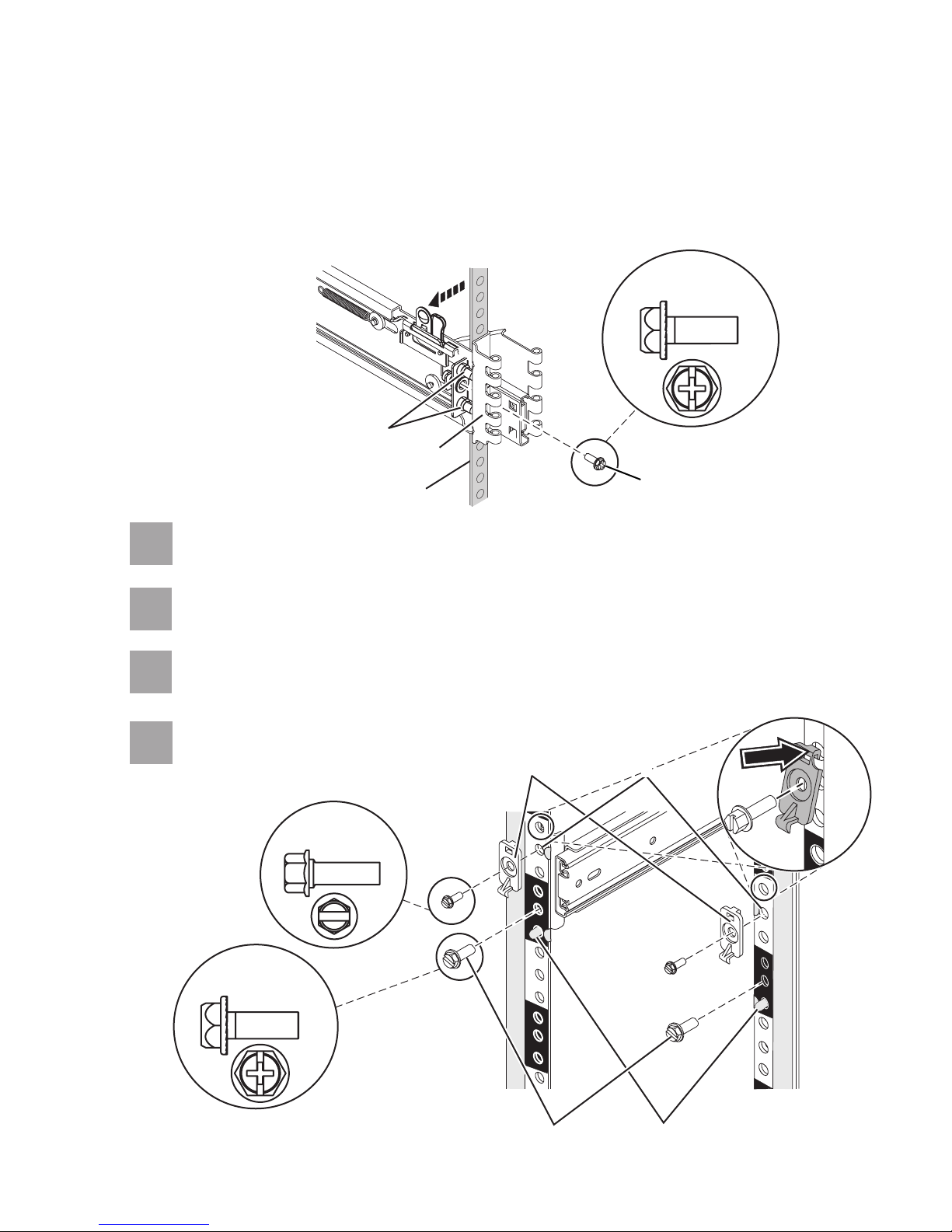
3.
Align the retracted back pins with the holes identified by the self-adhesive placement
dots. Place the rack flange between the slide-rail flange and the retracted alignment
pins .
E
E
FG
4.5
4.6
Press the back latch-assembly-release tab to extend the back alignment pins into the
4.
back of the rack.
C
C
Actual size
part 12J5289
E
G
F
From the back, finger-tighten one of the rack-retaining screws in the hole that is
located between the two back alignment pins .
From the front, finger-tighten one of the rack-retaining screws in the first hole
above the front alignment pin .
J
E
H
H
I
4.7
4.8
From the front, attach the latch bracket by inserting the hook into the rack hole above
the hole where you will place the latch bracket screw. Finger-tighten the screw.
Repeat steps 4.4 through 4.7 for
each slide rail assembly.
part 12J5289
L
Actual size
part 26H7213
Actual size
K
K
L
I
J
Page 7
5
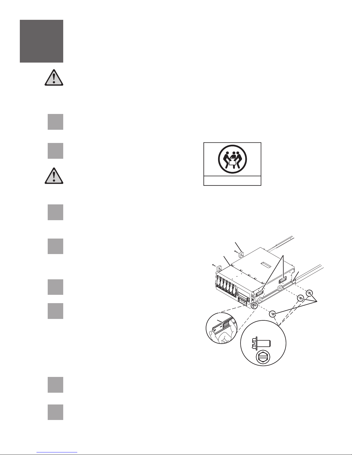
Install the server onto the slide rail assembly
Before installing the server onto the slide rail assembly, ensure that the leveling feet
are extended and that the stabilizer bracket is correctly installed to prevent the rack
from falling forward.
Before you begin: Read this entire task before completing any individual steps.
5.1
5.2
5.3
5.4
Attach the four blue knobs to the server . The blue knobs are used temporarily to rest
the server on the slide rails for installation. These knobs will be removed after the server is
secured to the slide rails.
Fully extend both slide rails.
Use safe practices when lifting.
Lift the server using the handles on each side, and position the server on the
extended slide rails. Align the three holes of the inner slide of the slide rails with the
three holes on each side of the server.
Using a screwdriver, attach the inner slide of
the slide rails to each side of the server by
using the system-to-slide-rail screws . Use
a screwdriver to tighten each of the screws.
D
BA
32-55 kg (70.5-121.2 lbs)
C
A
E
D
B
C
D
5.5
5.6
5.7
5.8
Remove the four blue knobs .B
Simultaneously release the blue safety latches
located near the front of each slide rail
F
assembly, and slowly push the server back into
the rack.
Pull the server back out and push it in
Tip:
again to make sure that the rails are aligned
correctly and that it glides smoothly.
Using a screwdriver, tighten the two rack-retaining screws to secure the slide rails to
the back of the rack.
Slide the server part of the way out of the rack. Using a screwdriver, tighten the front
two rack-retaining screws and the two latch-bracket screws on the front of the rack
to secure the slide rails.
E
F
Actual size
part 04N6485
Page 8
6
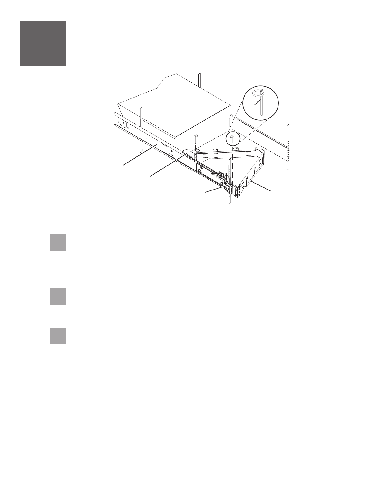
Install the cable-management arm
A
B
C
6.1
6.2
6.3
D
Locate the cable-management arm and the two pins .EA
Tip: If space is limited inside the rack, slide the server out part of the way to install the
cable-management arm.
From the back of the rack, use the pin to affix the cable-management arm to
the left slide-rail-management arm flange that is attached to the rack frame .
Use the second pin to affix the other end of the cable-management arm to the flange
that is attached to the sliding portion of the left slide rail assembly .
CB
A E
AE
E
D
Page 9

7
Cable the server and Operations Console
(LAN)
Operations Console is an installable component of iSeries Access for Windows . It allows you to use one or
more PCs to access and control, either remotely or locally, console and control panel functions.
If you are not using Operations Console to manage your server, go to task 8
the Thin Console
The following steps guide you through a LAN implementation of Operations Console. If you are using a local
console that is directly attached, follow the setup instructions in the IBM Systems Hardware Information
Center. For details about how to access the information center, see task 11 .Finish your system setup
If you are using a PC that is already in use as your system console, you do not need to power off the system
console to complete this procedure.
Prerequisite: This task requires one or more Ethernet cables that are not supplied with your server.
7.1
7.2
7.3
.
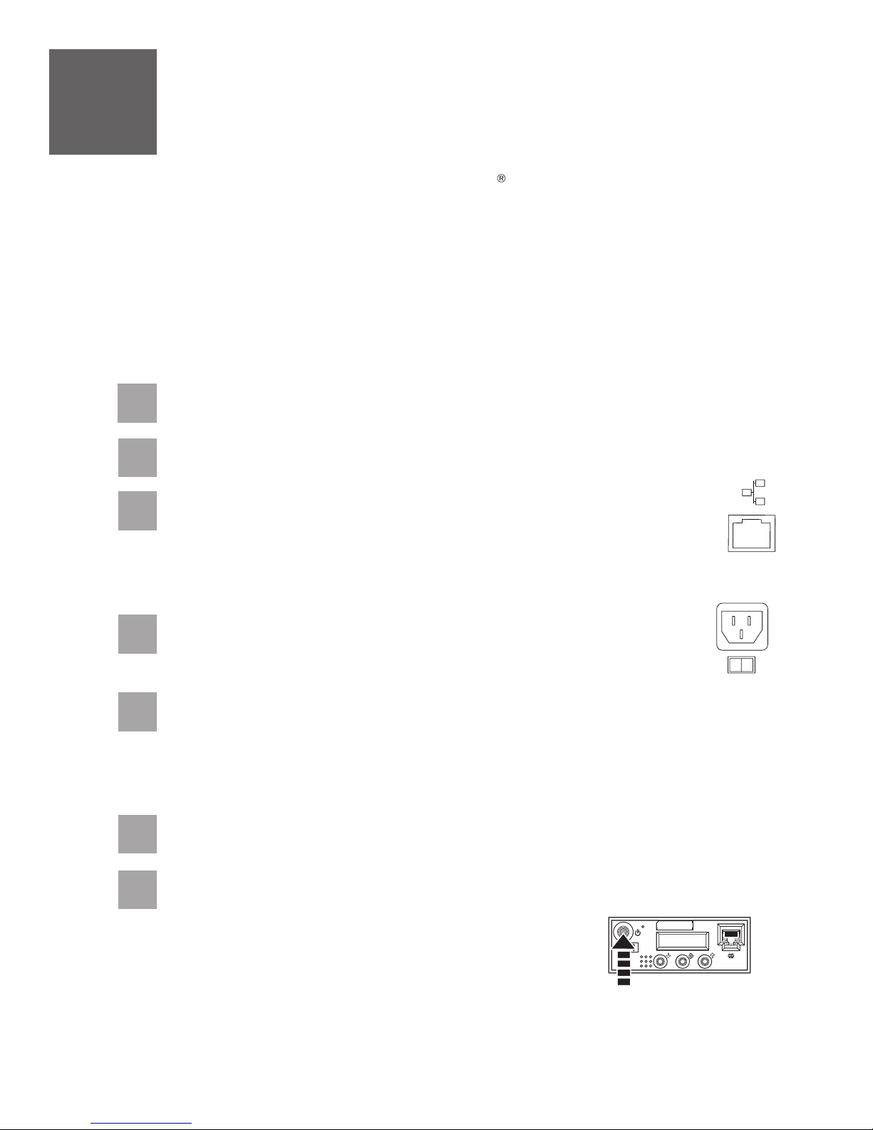
If necessary, connect an Ethernet cable from the PC that
will serve as the system console to your local network,
router, switch, or hub.
Connect another network cable from the same local
network, router, switch, or hub, to the first embedded
Ethernet port (P1-T5) or the adapter card in position C5
or C2 on the back of the server.
Route the server power cord through the rings or clamps,
if available, on the back of the server, and connect it to
the power supply port. Do not connect the server
power cord to a power source until instructed to do
so.
TM
(R)
Cable the server and
T5
7.4
7.5
If necessary, plug the power cord for your system
console (PC) into a power source, and turn it on.
Install iSeries Access for Windows onto the system console using the
Operations
Windows installed, skip to step 7.6.
1.
Insert the CD and select .
2.
Click and follow the prompts when the iSeries Access for Windows window is
displayed.
3.
Select or installation and select at least the following components.
Note:
User options.
Required Programs
5250 Display and Printer Emulator
minimum) is not installed
Operations Console
Click and follow the prompts.Next
4.
CD that was provided with your server. If you already have iSeries Access for
Setup and Operations iSeries Access for Windows
Next
Custom Full
The Operations Console component is not available using the Typical or PC5250
; if IBM Personal Communications V5.8 (V5.7 CSD 1
Setup and
Page 10

7.6
Start the Operations Console configuration wizard on the system console.
1.
Click .
Start > Programs > iSeries Access for Windows > Operations Console
Follow the steps in the wizard. Use the following information to enter any required data.
2.
7.7
7.8
Service host name
(interface name):
Target par tition:
Serial Number:
Service tools device ID:
Access password:
3.
Click to save the configuration and to exit the configuration wizard.Finish
Right-click the connection name and select to start your connection. The system
console will not complete the connection until you have completed step 7.10.
Connect your server to a power source. The control panel should be lit and display
N V=F
. The server is not yet powered on.
Use either the name of a current network interface, or a new
name for this connection.
Enter the number , even if you are not partitioning.
Enter the serial number located on the server control panel.
Use the default value .
Enter a password that you will remember. The password is case
sensitive and can be a maximum of 128 characters.
1
QCONSOLE
Connect
01 B
7.9
7.10
01 B N V=FNote:
If does not display, see the instructions in the IBM Systems Hardware
Information Center. For details about how to access the information center, see task 11
Finish your system setup
Press the white Power On button on the front of the server. There is a short delay before
the server powers on, of approximately 5 to 20 minutes. When the server powers on, the
control panel displays .01 B N V=F
When the LAN Service Tools Sign-on window is displayed, type your access password,
and then type (eight 1's) in both the service tools user ID and password fields.11111111
You have completed the basic setup. Go to task 11 .Finish your system setup
.
Page 11
8
The Thin Console provides a 5250 emulation session for an i5/OS logical partition on servers that are not
managed by a Hardware Management Console (HMC).
Cable the server and the Thin Console
If you are not using the Thin Console to manage your server, go to task 9
server.
This task assumes that you are setting up the Thin Console with a new server. If you are setting up the Thin
Console with an existing server, follow the instructions in the IBM Systems Hardware Information Center. For
details about how to access the information center, see task 11 .
Prerequisite:
This task requires an Ethernet cable and a monitor that are not supplied with your server.
8.1
8.2
8.3
8.4
Complete the Thin Console setup instructions provided with the Thin Console.
Select the keyboard language and press .Enter
Connect the other end of the Ethernet cable directly to the HMC port labeled
HMC1 or the port labeled HMC2 on the back of the server. No other console
device can be attached to the remaining HMC port.
Important: Use an Ethernet cable with a maximum length of 7.5 m (25 ft.).
Route the server power cord through the rings or clamps, if available, on the
back of the server, and connect it to the power supply port.
Finish your system setup
Cable the HMC and the
8.5
8.6
8.7
Connect your server to a power source. The control panel should be lit and display
N V=F
Tip: If does not display, see the instructions in the IBM Systems Hardware
Information Center. For details about how to access the information center, see task 11
Finish your system setup
When you are prompted on the Thin Console display, type a new HMC access password. This
password is case sensitive.
Press the white Power On button on the front of the server. There is a delay before the
server powers on, approximately 5 to 20 minutes. When the server powers on, the control
panel displays .01 B N V=F
Your Thin Console is now cabled and will be ready for login when the IPL is complete. Go
to task 11 .Finish your system setup
. The server is not yet powered on.
01 B N V=F
01 B
.
Page 12

9
An HMC is a system that connects to the server and manages it through a network.
Cable the HMC and the server
If you are not using an HMC to manage your server, skip this task and go to task 10
and twinaxial console
If you are using a rack-mounted HMC, these steps assume it is already installed in the rack.
If you need to install the HMC into the rack, follow the instructions in the IBM Systems Hardware Information
Center, and return to this guide when you are ready to begin cabling your HMC. For details about how to access
the information center, see task 11
9.1
9.2
9.3
.
Finish your system setup.
If you are using any optional adapters for the HMC, connect the cables to the appropriate
adapter connectors in the PCI slots of your server and HMC.
Route the power cords through the rings or clamps, if available, on the
back of the server, and connect to the server, monitor, and HMC. Do
not connect the power cords to a power source until instructed to
do so.
Important: Ensure that if there is a voltage switch next to the power connector on the
monitor, it is in the appropriate position for the voltage used in your geography.
Connect the mouse and keyboard cables to the appropriate ports on the back
of the HMC. If your mouse and keyboard use Universal Serial Bus (USB)
cables, you can connect these to the ports on the front of the HMC.
Cable the server
9.4
9.5
Attach the monitor cable to the monitor connector on the HMC and
tighten the screws.
Tip: If you are using the rack-mounted LCD monitor and keyboard (7316-TF3), use the
C2T-to-KVM adapter breakout cable to attach to the HMC.
If you are not using a modem, skip to step 9.6.
If you are using the integrated HMC modem, connect the telephone cable to the modem
and to the analog jack on the wall. If you are using an external modem, connect the
modem data cable to the external modem and to a serial port on the HMC. Then connect
the telephone cable to the external modem and to the analog jack on the wall.
Page 13

9.6
Connect the Ethernet cable to the Ethernet port on the HMC and to the
Ethernet port labeled HMC1 on the server.
For a stand-alone HMC, use the integrated Ethernet port. For the 7310-CR2 rack-mounted
HMC, use the bottom-right Ethernet port. For the 7310-CR3 rack-mounted HMC, use the
left port of the two planar board Ethernet ports.
9.7
9.8
9.9
9.10
9.11
If using an external modem, plug the power cord into the modem.
CAUTION:This product is equipped with a 3-wire (two conductor and a ground)
power cable and plug. Use this power cable with a properly grounded electrical
outlet to avoid electrical shock. (C018)
Plug the power cords for the monitor, HMC, and external modem into a power source. Do
not connect the server to a power source until instructed to do so.
Route the cables through the cable-management arm on the server and secure the
cables with the straps provided.
Start and configure the HMC, which includes the Guided Setup Wizard. You can find the
instructions for configuring the HMC in the IBM SystemsHardware Information Center. For
details about how to access the information center, see task 11 .Finish your system setup
Connect the server to a power source and wait for the control panel on the front of the
server to display . This might take several minutes.01
9.12
Press the white Power On button on the control panel.
You have completed the basic setup. Go to task 11 Finish your system setup.
Page 14

10
If you are not using a twinaxial console to manage your server, go to task 11 Finish your system setup.
Cable the server and twinaxial console
10.1
10.2
10.3
10.4
Route the power cords through the rings or clamps, if available, on the back of the server,
and connect to the server. Do not connect the power cords to a power source until
instructed to do so.
Connect the 8-port twinaxial attachment cable (Part Number 21F5093) to the twinaxial
adapter card (2746). This card should be located in position 5 or 2 on the back of the
server.
Connect a twinaxial cable from the workstation that you will be using as the system
console to port 0 on the 8-port twinaxial attachment cable.
Important: The workstation address of your console must be set to 0.
To set the address, see the information included with your workstation.
Connect one end of a telephone cable to the RJ11 connector of the adapter in position 3,
and the other end to an analog telephone jack.
10.5
10.6
10.7
10.8
If you are using any optional adapters, connect the cables to the appropriate adapter
connectors in the PCI slots of your server. If your server is in a rack, route the cables
through the cable-management arm and secure with the straps provided.
Connect your console to a power source and turn it on.
Connect your server to a power source, and wait for the control panel on the front of the server
to display . This might take several minutes.01
Press the white Power On button on the control panel.
Your console is now cabled and will be ready for login when the IPL is complete. Continue
to task 11 for details about how to access the information center.Finish your system setup
Page 15

11
You have completed the basic tasks to set up your server.
Finish your system setup
You can access the . Follow these steps to create a
customized checklist that helps you configure your server and console, install software, apply fixes, and
establish connections with your service provider:
now IBM Systems Hardware Information Center
11.1
11.2
11.3
Using a Web browser, go to www.ibm.com/systems/infocenter/hardware or go to the
preinstalled version on the HMC.
From the navigation bar, click Systems Hardware information System i
information Initial server setup Create a customized initial server setup
checklist.
Answer the questions in the interactive interview, and follow the procedures in the
resulting checklist.
If you cannot access the online version of the information center, it is also provided on a
CD with your system (SK3T-8159).
>>
>
Page 16

International Business Machines Corporation 2006, 2007
Printed in USA
September 2007
All Rights Reserved
Mail comments to:
IBM Corporation
Attention Department DDR
3605 Highway 52 North
Rochester, MN U.S.A. 55901-7829
Fax comments to:
1-800-937-3430 (U.S. or Canada)
1-507-253-5192 (outside the U.S. or Canada)
Internet URL: http://www.ibm.com/systems/infocenter/hardware
References in this publication to IBM products or
services do not imply that IBM intends to make
them available in every country or region.
i5/OS, IBM, the IBM logo, iSeries, and System i are
trademarks of International Business Machines Corporation
in the United States, other countries, or both.
Microsoft, Windows,Windows NT, and the Windows
logo are trademarks of Microsoft Corporation in
the United States, other countries, or both.
Other company, product, and service names may
be trademarks or service marks of others.
29R1717
SA41-5171-04
 Loading...