

Page 1

pSeries 7311 Model D10 and Model D20
Service Guide
SA38-0627-00
ERserver
IBM
Page 2

Page 3

pSeries 7311 Model D10 and Model D20
Service Guide
SA38-0627-00
ER ser ver
IBM
Page 4

First Edition (December 2002)
Before using this information and the product it supports, read the information in “Safety Notices” on page vii,
Appendix A, “Environmental Notices”, on page 201, and Appendix B, “Notices”, on page 203.
A reader’s comment form is provided at the back of this publication. If the form has been removed, address comments
to Information Development, Department H6DS-905-6C006, 11501 Burnet Road, Austin, Texas 78758-3493. To send
comments electronically, use this commercial internet address: aix6kpub@austin.ibm.com. Any information that you
supply may be used without incurring any obligation to you.
© International Business Machines Corporation, 2002. All rights reserved.
Note to U.S. Government Users -- Documentation related to restricted rights -- Use, duplication or disclosure is subject
to restrictions set forth is GSA ADP Schedule Contract with IBM Corp.
Page 5

Contents
Safety Notices........................vii
Rack Safety Instructions .....................vii
Electrical Safety .......................viii
Laser Safety Information .....................ix
Laser Compliance ......................ix
Data Integrity and Verification ..................xi
About This Book ......................xiii
ISO 9000 .........................xiii
Accessing Information .....................xiii
Related Publications ......................xiii
Trademarks.........................xiv
Chapter 1. Reference Information .................1
pSeries 7311 Model D10 Overview .................1
Model D10 I/O Subsystem Features .................1
I/O Subsystem PCI-X Slot LED Definitions ..............3
D10 Power ........................4
Subsystem Positioning and Cabling ................6
D10 I/O Subsystem Locations ...................10
7311 Model D10 I/O Subsystem Front Locations............10
7311 Model D10 I/O Subsystem Rear Locations ............11
Model D10 I/O Backplane Locations................12
D10 I/O Subsystem PHB ...................13
D10 Location Codes ......................14
Physical Location Code Table ..................14
7311 Model D10 I/O Subsystem Location Code Table ..........15
pSeries 7311 Model D20 Overview .................16
Model D20 I/O Subsystem Features.................16
Model D20 PCI-X Slots ....................16
Model D20 Power ......................18
Model D20 Location Codes....................33
AIX and Physical Location Code Table ...............33
Model D20Location Code Table .................34
Powering the System On and Off..................36
Power-On Self-Test ......................36
Specifications ........................37
Model D10 Specifications ...................37
Model D20 Specifications ...................38
External AC Power Cables ....................39
Service Inspection Guide ....................40
Chapter 2. Diagnostics Overview .................41
Power and Attention LEDs ....................41
Component LEDs ......................41
Resetting the LEDs .....................41
iii
Page 6

Checkpoints.........................41
FRU Isolation ........................42
Chapter 3. Maintenance Analysis Procedures (MAPs) ..........43
Chapter 4. Checkpoints ....................45
Chapter 5. Error Code to FRU Index ................47
Chapter 6. Using the Service Processor...............49
Chapter 7. Using System Management Services............51
Chapter 8. Removal and Replacement Procedures ...........53
Safety Considerations .....................53
Handling Static-Sensitive Devices .................54
Stopping the System ......................55
Starting the System ......................55
7311 Model D10 I/O Subsystem Removal and Replacement Procedures.....56
Model D10 FRU Replacement Procedure List ............56
D10 Service Position .....................57
D10 Operating Position ....................57
D10 Front Bezel ......................58
D10 Covers ........................59
D10 PCI Adapters......................61
Hot-Pluggable PCI Adapter...................63
PCI Hot-Plug Manager Access .................71
PCI Adapter or Blank Filler Removal From a Cassette Assembly ......74
Replacing an Adapter in a PCI Adapter Cassette ...........86
Short Adapter or Blank Filler Installation ..............90
Long Adapter Installation ...................106
D10Fan........................120
D10 RIO Cable ......................121
D10 RIO Bus Adapter ....................121
D10 I/O Backplane Assembly .................122
D10 Power Supply .....................123
7311 Model D20 I/O Subsystem Removal and Replacement Procedures ....124
Model D20 FRU Replacement Procedure List ............124
D20 Service Position ....................125
D20 Operating Position ...................126
D20 Service Access Cover ..................127
D20 Front Bezel ......................129
D20 Operator Panel.....................131
D20 Blowers .......................134
D20 Cooling Blowers Cable ..................137
D20 RIO Bus Adapter Assembly ................139
D20 PCI Adapters .....................142
D20 Hot-Plug Disk Drives ...................160
D20 Disk Drive Cage ....................165
D20 Disk Drive Backplane ..................167
iv Eserver pSeries 7311 Model D10 and Model D20 Service Guide
Page 7

D20 Power Supplies ....................169
D20 Power Supply Bulkhead ..................172
D20 I/O Backplane .....................175
Chapter 9. Parts Information ..................179
7311 Model D10 I/O Subsystem..................180
D10 I/O Backplane and Cooling.................180
D10 Power and Cooling ...................182
D10 SPCN, RIO, and Rack Beacon Cables .............184
D10 Rack Mounting Enclosure .................185
Model D20 I/O Subsystem ...................186
D20 I/O Backplane and Cabling.................186
D20 PCI Slots ......................188
D20 Power, RIO ......................190
D20 Operator Panel.....................192
D20 Fans and Disk Drives ..................194
D20 Covers and Brackets ...................196
D20 RIO, SPCN, and Rack Beacon Cables .............197
Power Cables........................198
Appendix A. Environmental Notices................201
Product Recycling and Disposal..................201
Environmental Design .....................201
Acoustical Noise Emissions ...................201
pSeries 7311 Model D10 Declared Acoustical Noise Emissions ......201
pSeries 7311 Model D20 Declared Acoustical Noise Emissions ......202
Appendix B. Notices .....................203
Index ..........................205
Contents v
Page 8

vi Eserver pSeries 7311 Model D10 and Model D20 Service Guide
Page 9

Safety Notices
A
danger
notice indicates the presence of a hazard that has the potential of causing
death or serious personal injury. Danger notices appear on the following pages:
v viii
v 53
A
caution
notice indicates the presence of a hazard that has the potential of causing
moderate or minor personal injury. Caution notices appear on the following pages:
v viii
v viii
v ix
v ix
v 53
v 54
Note: For a translation of these notices, see
System Unit Safety Information
, order
number SA23-2652.
Rack Safety Instructions
v Do not install this unit in a rack where the internal rack ambient temperatures will
exceed 35 degrees C.
v Do not install this unit in a rack where the air flow is compromised. Any side, front or
back of the unit used for air flow through the unit must not be in direct contact with
the rack.
v Care should be taken to ensure that a hazardous condition is not created due to
uneven mechanical loading when installing this unit in a rack. If the rack has a
stabilizer it must be firmly attached before installing or removing this unit.
v Consideration should be given to the connection of the equipment to the supply
circuit so that overloading of circuits does not compromise the supply wiring or
overcurrent protection. To provide the correct power connection to the rack, refer to
the rating labels located on the equipment in the rack to determine the total power
requirement for the supply circuit.
v An electrical outlet that is not correctly wired could place hazardous voltage on the
metal parts of the system or the devices that attach to the system. It is the
responsibility of the customer to ensure that the outlet is correctly wired and
grounded to prevent an electrical shock.
vii
Page 10

Electrical Safety
Observe the following safety instructions any time you are connecting or disconnecting
devices attached to the workstation.
In the system you are about to setup or service:
v The ac power interface connector is considered the main power disconnect device.
v This system has redundant power supply capabilities, meaning that it has the ability
to have two power supplies running simultaneously in the same system unit. When
instructed to disconnect the power source, ensure that all power cables have been
unplugged.
DANGER
An electrical outlet that is not correctly wired could place hazardous voltage
on metal parts of the system or the devices that attach to the system. It is the
responsibility of the customer to ensure that the outlet is correctly wired and
grounded to prevent an electrical shock.
Before installing or removing signal cables, ensure that the power cables for
the system unit and all attached devices are unplugged.
When adding or removing any additional devices to or from the system,
ensure that the power cables for those devices are unplugged before the
signal cables are connected. If possible, disconnect all power cables from the
existing system before you add a device.
Use one hand, when possible, to connect or disconnect signal cables to
prevent a possible shock from touching two surfaces with different electrical
potentials.
During an electrical storm, do not connect cables for display stations, printers,
telephones, or station protectors for communications lines.
D05
CAUTION:
This product is equipped with a three-wire power cable and plug for the user’s
safety. Use this power cable with a properly grounded electrical outlet to avoid
electrical shock.
C01
CAUTION:
This unit has more than one power supply cord. To reduce the risk of electrical
shock, disconnect two power supply cords before servicing.
C21
viii Eserver pSeries 7311 Model D10 and Model D20 Service Guide
Page 11

Laser Safety Information
CAUTION:
This product may contain a CD-ROM, DVD-ROM, or laser module on a PCI card,
which are class 1 laser products.
C30
Laser Compliance
All lasers are certified in the U.S. to conform to the requirements of DHHS 21 CFR
Subchapter J for class 1 laser products. Outside the U.S., they are certified to be in
compliance with the IEC 825 (first edition 1984) as a class 1 laser product. Consult the
label on each part for laser certification numbers and approval information.
CAUTION:
All IBM laser modules are designed so that there is never any human access to
laser radiation above a class 1 level during normal operation, user maintenance,
or prescribed service conditions. Data processing environments can contain
equipment transmitting on system links with laser modules that operate at
greater than class 1 power levels. For this reason, never look into the end of an
optical fiber cable or open receptacle. Only trained service personnel should
perform the inspection or repair of optical fiber cable assemblies and receptacles.
C25, C26
Safety Notices ix
Page 12

x Eserver pSeries 7311 Model D10 and Model D20 Service Guide
Page 13
Data Integrity and Verification
IBM computer systems contain mechanisms designed to reduce the possibility of
undetected data corruption or loss. This risk, however, cannot be eliminated. Users who
experience unplanned outages, system failures, power fluctuations or outages, or
component failures must verify the accuracy of operations performed and data saved or
transmitted by the system at or near the time of the outage or failure. In addition, users
must establish procedures to ensure that there is independent data verification before
relying on such data in sensitive or critical operations. Users should periodically check
the IBM support websites for updated information and fixes applicable to the system and
related software.
xi
Page 14

xii Eserver pSeries 7311 Model D10 and Model D20 Service Guide
Page 15

About This Book
This book provides maintenance information that is specific to the 7311 Model D10 and
Model D20 I/O subsystems, as well as adapters and attached devices that do not have
their own service information. In this book, the I/O subsystems are referred to as the
Model D10 or the Model D20 I/O subsystem.
MAPs that are common to all systems are contained in the
RS/6000
Eserver
pSeries
Diagnostic Information for Multiple Bus Systems
.
This book is used by the service representative to repair system failures. This book
assumes that the service representative has had training on the processor subsystem
to which an I/O subsystem is attached, in addition to training on the I/O subsystem
drawer.
ISO 9000
ISO 9000 registered quality systems were used in the development and manufacturing
of this product.
Accessing Information
Documentation for the IBM Eserver pSeries is available online. Visit the IBM Eserver
pSeries Information Center at
http://publib16.boulder.ibm.com/pseries/en_US/infocenter/base.
v To access the pSeries publications, click Hardware documentation.
v To view information about the accessibility features of Eserver pSeries hardware
and the AIX operating system, click AIX and pSeries accessibility.
Related Publications
The following publications provide additional information about your system:
v The
D10 I/O Drawer Installation Guide
, order number SA23-1295, contains
information on how to install the Model D10 I/O subsystem.
v The
D20 I/O Drawer Installation Guide
, order number SA23-1296, contains
information on how to install the Model D20 I/O subsystem.
v The Eserver
pSeries 630 Model 6C4 and Model 6E4 User’s Guide
, order number
SA38-0606, contains information to help users use the system, use the service aids,
and solve minor problems.
v The
RS/6000
Eserver
pSeries Diagnostic Information for Multiple Bus Systems
,
order number SA38-0509, contains diagnostic information, service request numbers
(SRNs), and failing function codes (FFCs).
v The
RS/6000
Eserver
pSeries Adapters, Devices, and Cable Information for
Multiple Bus Systems
, order number SA38-0516, contains information about
adapters, devices, and cables for your system. This manual is intended to
xiii
Page 16

supplement the service information found in the
RS/6000
Eserver
pSeries
Diagnostic Information for Multiple Bus Systems
.
v The
Site and Hardware Planning Guide
, order number SA38-0508, contains
information to help you plan your installation.
v The
System Unit Safety Information
, order number SA23-2652, contains translations
of safety information used throughout this book.
v The
PCI Adapter Placement Reference
, order number SA38-0538, contains
information regarding slot restrictions for adapters that can be used in this system.
Trademarks
The following terms are trademarks of International Business Machines Corporation in
the United States, other countries, or both:
v AIX
v Electronic Service Agent
v Eserver
v IBM
v LANstreamer
v PowerPC
v pSeries
v RS/6000
Other company, product, and service names may be trademarks or service marks of
others.
xiv Eserver pSeries 7311 Model D10 and Model D20 Service Guide
Page 17
Chapter 1. Reference Information
This chapter provides reference information for the Model D10 and Model D20 I/O
subsystems.
pSeries 7311 Model D10 Overview
The Model D10 is a 19-inch, rack-mountable I/O subsystem that is attached to a
processor subsystem drawer to extend the system’s capacity for I/O adapters. The I/O
drawer includes redundant concurrently maintainable power and cooling.
Five PCI-X slots and one PCI slot are available for PCI adapters. PCI adapters are
installed through the rear of the I/O subsystem using PCI adapter cassettes. Because
the PCI slots support hot-pluggable adapters, the I/O subsystem can have adapters
installed without turning off power or removing covers. The Model D10 is 4 EIA units
high and two Model D10s can be installed side-by-side in a 19-inch rack enclosure.
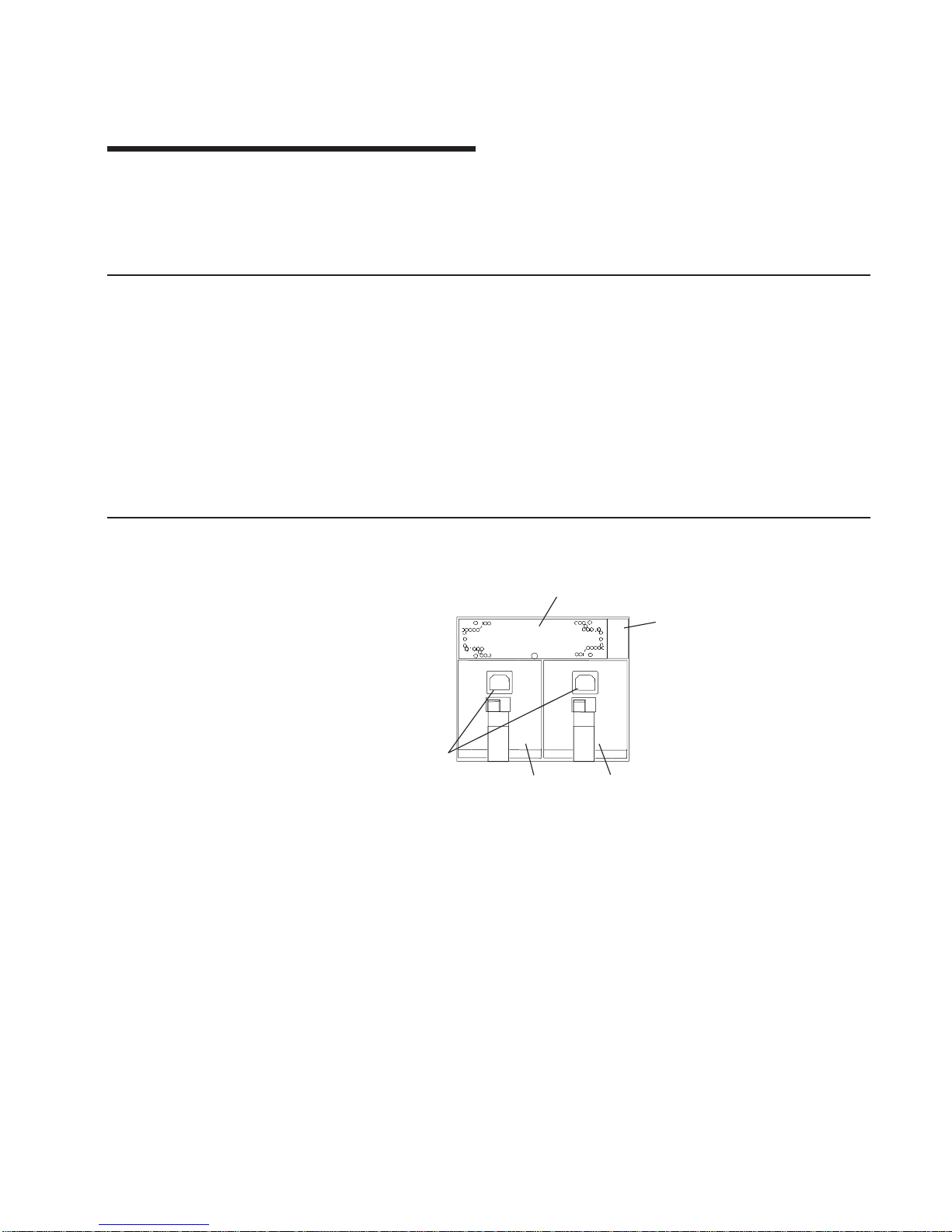
Model D10 I/O Subsystem Features
The following figure shows the I/O subsystem from the front.
2
3
1
5
4
1 Cooling Fan 3 Power Supply 1, Power Supply
2
2 Power cord channel 4 Power cord receptacles
1
Page 18
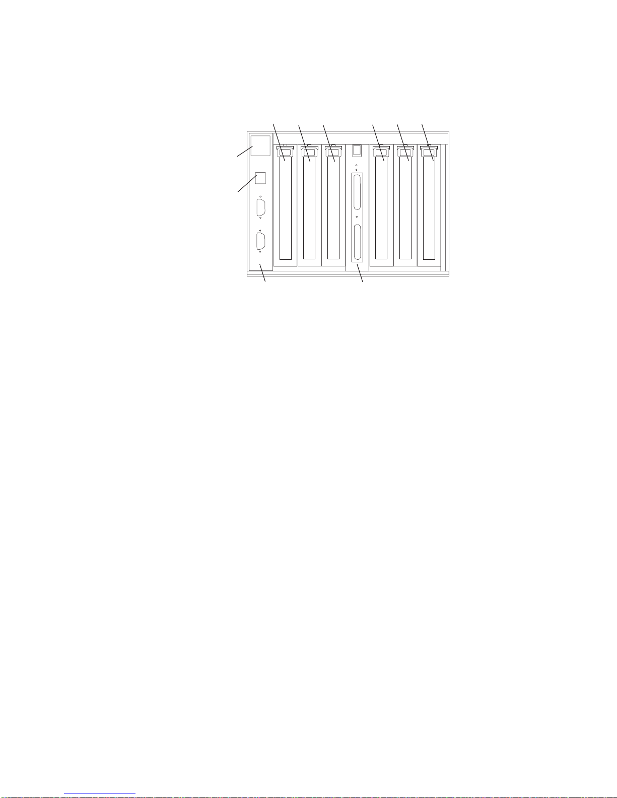
The following figure shows the I/O subsystem from the rear.
1
23 456
1
23
4
56
78
9
10
1 PCI adapter slot 1 6 PCI-X adapter slot 6
2 PCI-X adapter slot 2 7 RIO bus adapter card
Upper connector 0
Lower connector 1
3 PCI-X adapter slot 3 8 SPCN connector card
Upper connector J15
Lower connector J16
4 PCI-X adapter slot 4 9 Rack beacon connector
5 PCI-X adapter slot 5 10 Power cord channel
D10 Operator Indicators
v LED indicators visible on each PCI adapter cassette
v LED indicators on the I/O subsystem backplane
v Attention/Identify LEDs for power supplies and fans
D10 PCI-X Slots
The Model D10 has six PCI adapter slots. Five PCI-X slots and one PCI slot. Adapters
are installed and removed using a PCI adapter cassette which allows adapters to be
installed without turning off the power or opening the I/O subsystem covers.
The slots are numbered on the rear of the chassis from left to right 1 through 6. PCI
adapters are installed using an adapter cassette. The adapter cassette shows two LEDs
for each adapter. There is a green power indicator LED (upper) and an amber
fault/identify LED (lower). Slot 1 is a 5V PCI slot. Slots 2 through 6 are 3.3V PCI-X.
2 Eserver pSeries 7311 Model D10 and Model D20 Service Guide
Page 19

I/O Subsystem PCI-X Slot LED Definitions
The green LED (viewed on the rear of the PCI adapter cassette when installed) is used
to indicate the state of the PCI slot during removal and replacement of an adapter.
3
2
1
PCI LED (Green) Indication PCI Slot Status Definition
Off Off Slot power is Off. it is safe to
remove or replace adapters.
On (not flashing) On Slot power is On. Do not
remove or replace adapters
Flashing slowly (one flash per
second)
Indicates slot has been
identified by the software. Do
not remove or replace adapters
at this time.
Flashing rapidly (six to eight
flashes per second)
Indicates slot is ready
removing or replacing an
adapter.
Chapter 1. Reference Information
3
Page 20

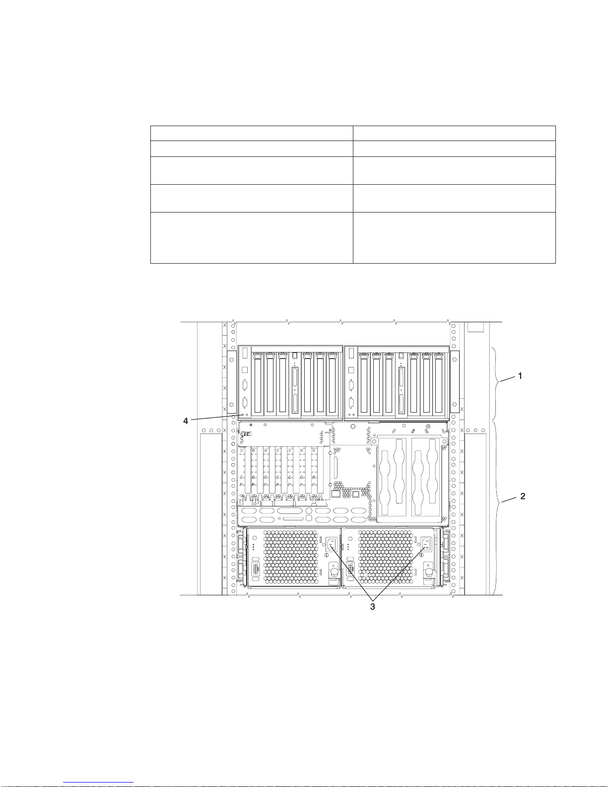
D10 Power
The following figure shows a processor subsystem and two I/O subsystems from the
front. Each unit has two power supplies and two power cords for redundancy. Connect
the power cords from one side of the system to one power distribution bus in the rack.
Connect the power cords from the other side of the system to a different power
distribution bus in the rack. A separate branch power line for each side of the rack must
be utilized to ensure that the systems in a rack keep running if power is interrupted.
1
1
2
1
3
1 Power supplies, power
receptacles
3 One 7038 Model 6M2
processor subsystem
2 Two Model D10 I/O
subsystems mounted
side-by-side.
Model D10 I/O subsystem has two power supplies. Either power supply is capable of
providing the necessary voltages and currents, independent of the other power supply.
Each power supply provides 5V dc, 3.3V dc, -12V dc, and 5V dc standby. The power
supplies are hot-pluggable and may be changed one at a time while the system is
operational.
4 Eserver pSeries 7311 Model D10 and Model D20 Service Guide
Page 21
The following table describes power supply LED indicators that are available on the
Model D10.
Status of LED Power Supply LED
Off Power Source not connected
Blinking green LED System power source connected, but power is
not turned on
Blinking green LED, visibly begins to blink
faster after the power button has been pressed.
System power connected, the power on button
has been pressed and power-on initiated
Solid (not blinking) green LED, (There is
approximately a 30 second transition period
from the time the power on button is pressed to
the time the power LED is on solid.)
System power connected and turned on
The following figure shows a processor subsystem and two I/O subsystems from the
rear.
1 Model D10 I/O subsystem 3 Processor subsystem power
supplies, power receptacles
2 7038 Model 6M2 processor
subsystem
4 I/O backplane power (green)
and fault/identify (amber) LEDs
Chapter 1. Reference Information
5
Page 22

D10 Cooling
Fans mounted inside each I/O subsystem power supply and an additional fan mounted
on the front of the subsystem provide cooling. The power supplies and the fan can be
removed and replaced with the power turned on as long as only one is removed from
the I/O subsystem at a time.
D10 Input/Output Ports
The connector ports on the rear of the Model D10 I/O subsystem are used to connect
the RIO cables, the SPCN cables, and the rack-beacon LED.
Subsystem Positioning and Cabling
The I/O subsystem can be installed in a standard 19-inch EIA rack in any location. The
cables that connect the subsystems allow some flexibility in drawer placement, but the
I/O subsystems should be located above the connected processor subsystem in the
same rack.
Up to eight Model D10 I/O subsystems can be connected to a processor subsystem.
Each I/O subsystem is connected to the processor subsystem using a system power
control network (SPCN) cable loop and a remote I/O (RIO) cable loop. One SPCN
cable loop is needed to connect the I/O subsystems to one processor subsystem. Up to
four I/O subsystems are connected to the same processor subsystem using a single
RIO loop.
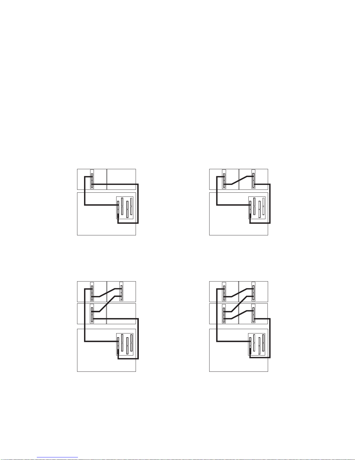
SPCN Cabling
I/O subsystem SPCN cables are connected to the processor subsystem unit using a
loop configuration. The SPCN cables are connected in a loop so that the system has
two paths to each I/O subsystem. A total of eight I/O subsystems are supported on one
SPCN loop.
One I/O Subsystem, Two I/O Subsystems:
The illustration on the left shows one I/O
subsystem connected to the processor subsystem. The illustration on the right shows
two I/O subsystems connected to the processor subsystem using one SPCN loop.
0
1
1
J15
J16
0
1
J15
J16
J15
J16
0
6 Eserver pSeries 7311 Model D10 and Model D20 Service Guide
Page 23

Four I/O Subsystems, Eight I/O Subsystems:
The illustration on the left shows four
I/O subsystems connected to the processor subsystem using one SPCN loop. The
illustration on the right shows eight I/O subsystems connected to the processor
subsystem using one SPCN loop.
1
J15
J16
J15
J16
J15
J16
J15
J16
J15
J16
J15
J16
J15
J15
J15
J16
J16
J16
0
1
J15
J16
J15
J16
J15
J16
0
Chapter 1. Reference Information 7
Page 24
RIO Cabling
I/O subsystems are connected to the processor subsystem through remote I/O (RIO)
cable loops. The cable loops are connected to ports that are available from the rear of
the processor subsystem. The RIO cables are connected in loops so that the system
has two paths to each I/O subsystem.
Up to four I/O subsystems can be connected to a system using one RIO loop. The
system can have up to four RIO loops. Eight I/O drawers can be connected to the
processor subsystem in a variety of cabling configurations. For optimum performance,
connect the RIO loops in a configuration that spreads multiple I/O drawers across as
many RIO loops as possible. For valid cabling examples, see the following illustrations.
One I/O Subsystem, Two I/O Subsystems:
The illustration on the left shows one I/O
subsystem drawer connected to the system unit. The illustration on the right shows two
I/O subsystem drawers connected to the system unit using one RIO loop.
0
1
0
1
0
1
1
0
2
1
Three I/O Subsystems, Four I/O Subsystems:
The illustration on the left figure
shows three I/O subsystem drawers connected to the system unit using one RIO loop.
The illustration on the right shows four I/O subsystem drawers connected to the system
unit using one RIO loop.
0
0
1
1
0
0
0
0
0
0
0
1
1
1
1
1
1
1
8 Eserver pSeries 7311 Model D10 and Model D20 Service Guide
Page 25

Eight I/O Subsystems, Two RIO Loops:
The following figure shows eight I/O
subsystem drawers connected to the system unit using two RIO loops.
0
0
0
0
1
1
1
1
0
1
0
0
0
0
1
1
1
1
Chapter 1. Reference Information 9
Page 26
D10 I/O Subsystem Locations
This system uses physical location codes to provide mapping of the failing field
replaceable units. The location codes are produced by the processor subsystem’s
firmware and AIX. For information about how to read a location code, see the service
guide for the processor subsystem to which your I/O subsystem is connected.
7311 Model D10 I/O Subsystem Front Locations
1
2
3
4
1 Cooling fan 3 Power Supply 2
U0.
dd
-V2
2 Power cord channel 4 Power Supply 1
U0.
dd
-V1
10 Eserver pSeries 7311 Model D10 and Model D20 Service Guide
Page 27
7311 Model D10 I/O Subsystem Rear Locations
1
23 456
1
23
4
56
78
9
10
1 PCI adapter slot 1
U0.
dd
-P1-I1
6 PCI-X adapter slot 6
U0.dd-P1-I6
2 PCI-X adapter slot 2
U0.
dd
-P1-I2
7 RIO bus adapter card
U0.dd-P1.1
3 PCI-X adapter slot 3
U0.
dd
-P1-I3
8 SPCN connector card
U0.dd-P1 (part of the I/O
backplane FRU)
4 PCI-X adapter slot 4
U0.
dd
-P1-I4
9 Rack beacon connector
5 PCI-X adapter slot 5
U0.
dd
-P1-I5
10 Power cord channel
Note: In the preceding table,ddis equal to the number assigned to each I/O
subsystem by the connected processor subsystem.
Chapter 1. Reference Information 11
Page 28
Model D10 I/O Backplane Locations
The following illustration of the I/O backplane identifies the primary connectors used in
your subsystem.
1
2
3
4
5
6
7
8
9
10
11
12
1 PCI adapter connector 1 7 SPCN connector
2 PCI-X adapter connector 2 8 VPD module
3 PCI-X adapter connector 3 9 VPD module pin 1 orientation
4 PCI-X adapter connector 4 10 RIO bus adapter connector
5 PCI-X adapter connector 5 11 Fan connector
6 PCI-X Adapter connector 6 12 Power supply connectors
12 Eserver pSeries 7311 Model D10 and Model D20 Service Guide
Page 29
D10 I/O Subsystem PHB
Each 7311 Model D10 I/O Subsystem has two PHBs through which the PCI slots are
connected.
1
23 456
Slot PHB Slot Characteristics
1 1 64-bit 5V, 33 MHz
2 1 64-bit 3.3V, 133 MHz
3 1 64-bit 3.3V, 133 MHz
4 2 64-bit 3.3V, 133 MHz
5 2 64-bit 3.3V, 133 MHz
6 2 64-bit 3.3V, 133 MHz
Chapter 1. Reference Information
13
Page 30

D10 Location Codes
This system (processor subsystem and attached I/O subsystems) use physical location
codes in conjunction with AIX location codes to provide mapping of failing field
replaceable unit (FRU). The location codes are produced by the processor subsystem’s
firmware and AIX. For information about how to read a location code, see the service
guide for the processor subsystem to which your I/O subsystem is connected.
Physical Location Code Table
This section covers the AIX and Physical Location Code tables for the Model D10.
The tables in this section contain the location codes for I/O subsystems when they are
attached to the system unit. In the tables, the location code for the I/O subsystem
number is represented by
dd
. The first time that an installed system is powered on, the
I/O subsystems are numbered. For example, if a system is first powered on with eight
I/O subsystems connected, the
dd
value for the subsystems should be numbered from
2 through 9.
Note: If the system was powered on with I/O subsystems connected before delivery to
the customer, the I/O subsystem location codes for the connected I/O
subsystems is permanently set.
If at a later time, an I/O subsystem is removed from the system and a different I/O
subsystem is substituted, the substitute is assigned the next higher number available for
its value of
dd
, which in the earlier example, is 10. If the original I/O subsystem is
reinstalled in the system configuration, the system uses the original
dd
value for the I/O
subsystem.
To keep the system from renumbering the I/O drawer when an I/O backplane is
replaced, the VPD module from the old I/O backplane must be moved over to the new
I/O backplane.
The following diagram defines each part of a location code.
Ux.dd-xx-yy
||||
||||
|||yyThis code is used for the next component (yy, yy, yy, ...)
| | xx This code is used for the next component (Px, Fx, Vx, ...)
| dd This code is the location code for the I/O drawer (2 to 63)
Ux This code normally identifies the rack in which a drawer is installed.
The x will always be zero (0) for this system.
14 Eserver pSeries 7311 Model D10 and Model D20 Service Guide
Page 31

7311 Model D10 I/O Subsystem Location Code Table
The following table lists the location codes for a D10 I/O subsystem. The location code
for the I/O subsystem connected to a system unit is U0.
dd
(whereddcan be any
number from 2 through 63).
FRU Name Physical Location Code
Model D10 I/O Drawer U0.
dd(dd
= any number from 2 through 63)
I/O subsystem 1 drawer U0.
dd
I/O backplane U0.dd-P1
RIO connector riser card U0.
dd
-P1.1
RIO port 0 (upper connector) U0.
dd
-P1.1/Q1
RIO port 0 cable U0.
dd
-P1.1/Q1#
RIO port 1 (lower connector) U0.
dd
-P1.1/Q2
RIO port 1 cable U0.
dd
-P1.1/Q2#
PHB1 U0.
dd
-P1
EADS_X under PHB1 U0.
dd
-P1
PCI slot 1 U0.
dd
-P1/I1
PCI slot 1 adapter U0.
dd
-P1-I1
PCI slot 2 U0.
dd
-P1/I2
PCI slot 2 adapter U0.
dd
-P1-I2
PCI slot 3 U0.
dd
-P1/I3
PCI slot 3 adapter U0.
dd
-P1-I3
PHB2 U0.
dd
-P1
EADS_X under PHB2 U0.
dd
-P1
PCI slot 4 U0.
dd
-P1/I4
PCI slot 4 adapter U0.
dd
-P1-I4
PCI slot 5 U0.
dd
-P1/I5
PCI slot 5 adapter U0.
dd
-P1-I5
PCI slot 6 U0.
dd
-P1/I6
PCI slot 6 adapter U0.
dd
-P1-I6
Power supply 1 (with 2 fans) U0.
dd
-V1
Power supply 2 (with 2 fans) U0.
dd
-V2
Cooling fan 5 U0.
dd
-F5
Rack indicator connector (4-pins) U0.
dd
-P1/Q3
SPCN connector J15 U0.
dd
-P1/Q4
SPCN connector J16 U0.
dd
-P1/Q5
Subsystem VPD U0.
dd
-P1
Chapter 1. Reference Information
15
Page 32

pSeries 7311 Model D20 Overview
The Model D20 is a 19-inch, rack-mountable I/O subsystem that is attached to a
processor subsystem to extend the system’s capacity for I/O adapters and disk drives.
The I/O subsystem includes redundant concurrently maintainable power and cooling.
Seven PCI slots are available for PCI adapters. Because the PCI slots support
hot-pluggable adapters, the I/O subsystem can have adapters installed without turning
off power. The Model D20 is 4 EIA units high and and compatible with 19-inch EIA rack
enclosures.
Model D20 I/O Subsystem Features
The features of the Model D20 enable this I/O subsystem to extend the input/output
capabilities of the processor subsystem. Features such as PCI-X adapters, and internal
SCSI disk drives are supported.
Model D20 Operator Indicators
v LED indicators visible on each PCI adapter light-pipe
v LEDs for power on, attention, SCSI activity
v Attention/Identify LEDs
v Rack Beacon
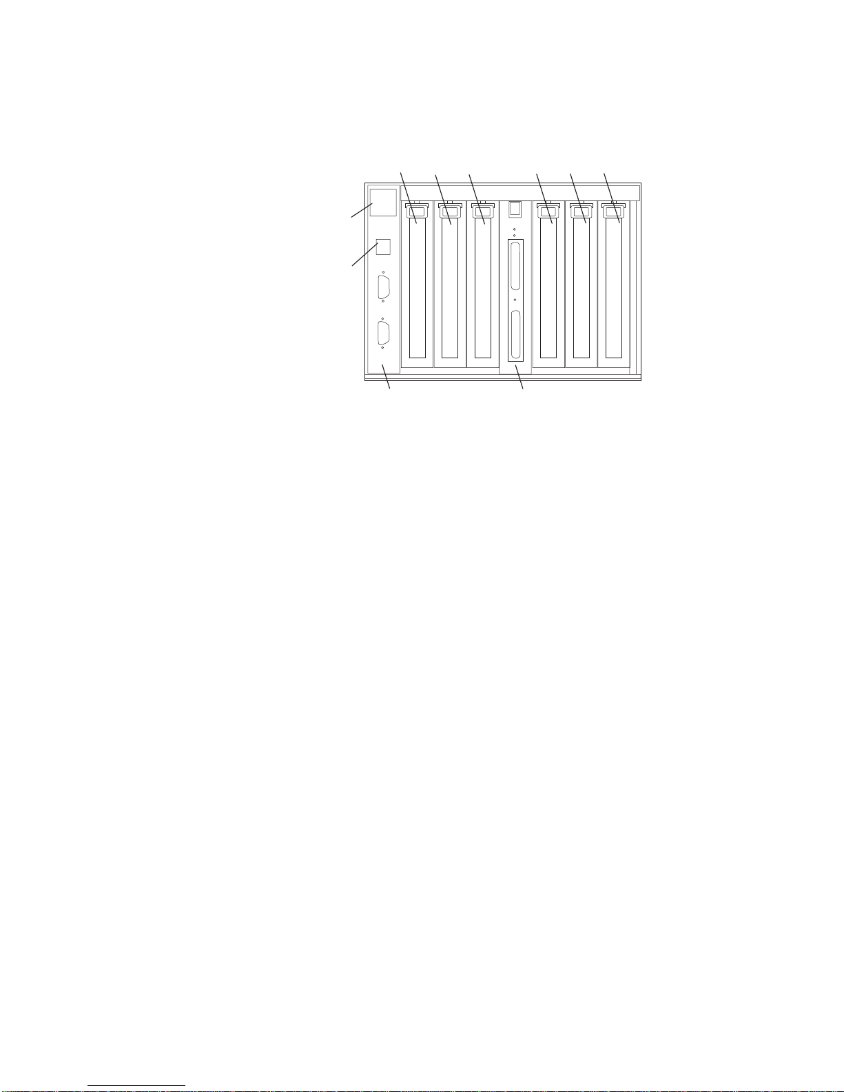
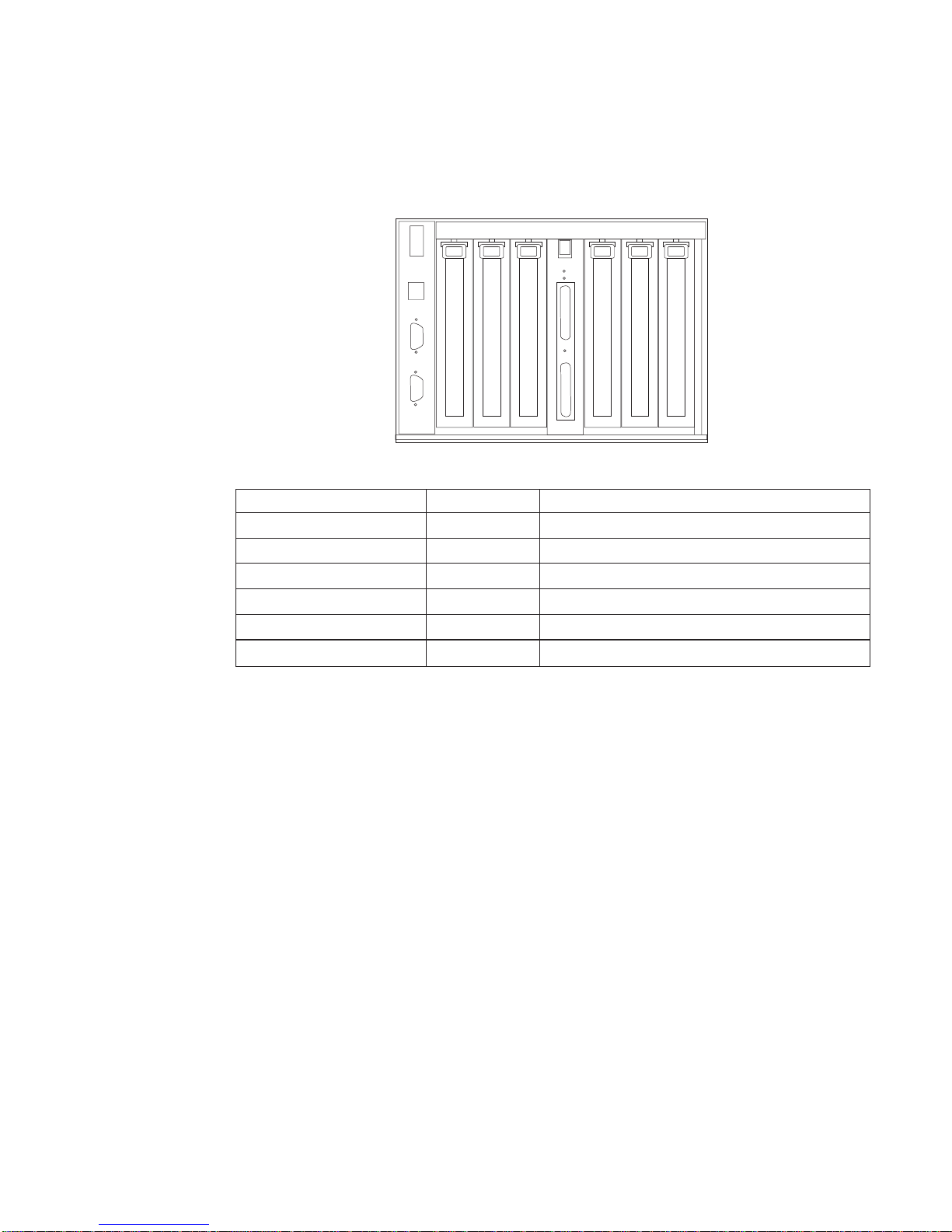
Model D20 PCI-X Slots
Seven PCI-X slots are available. The slots are 64-bit capable at up to 133 Mhz, 3.3
volts. The slots are numbered on the rear of the chassis from left to right 1 through 7.
The I/O backplane and each I/O slot have green power indicator LEDs and amber
identify LEDs. The following illustration shows the LED locations when viewing from the
16 Eserver pSeries 7311 Model D10 and Model D20 Service Guide
Page 33

rear of the I/O drawer.
123
4
567
A
A
A
B
B
B
1 PCI-X Expansion Slot 1 6 PCI-X Expansion Slot 6
2 PCI-X Expansion Slot 2 7 PCI-X Expansion Slot 7
3 PCI-X Expansion Slot 3 A Green Power LEDs
4 PCI-X Expansion Slot 4 B Amber Identify LEDs
5 PCI-X Expansion Slot 5
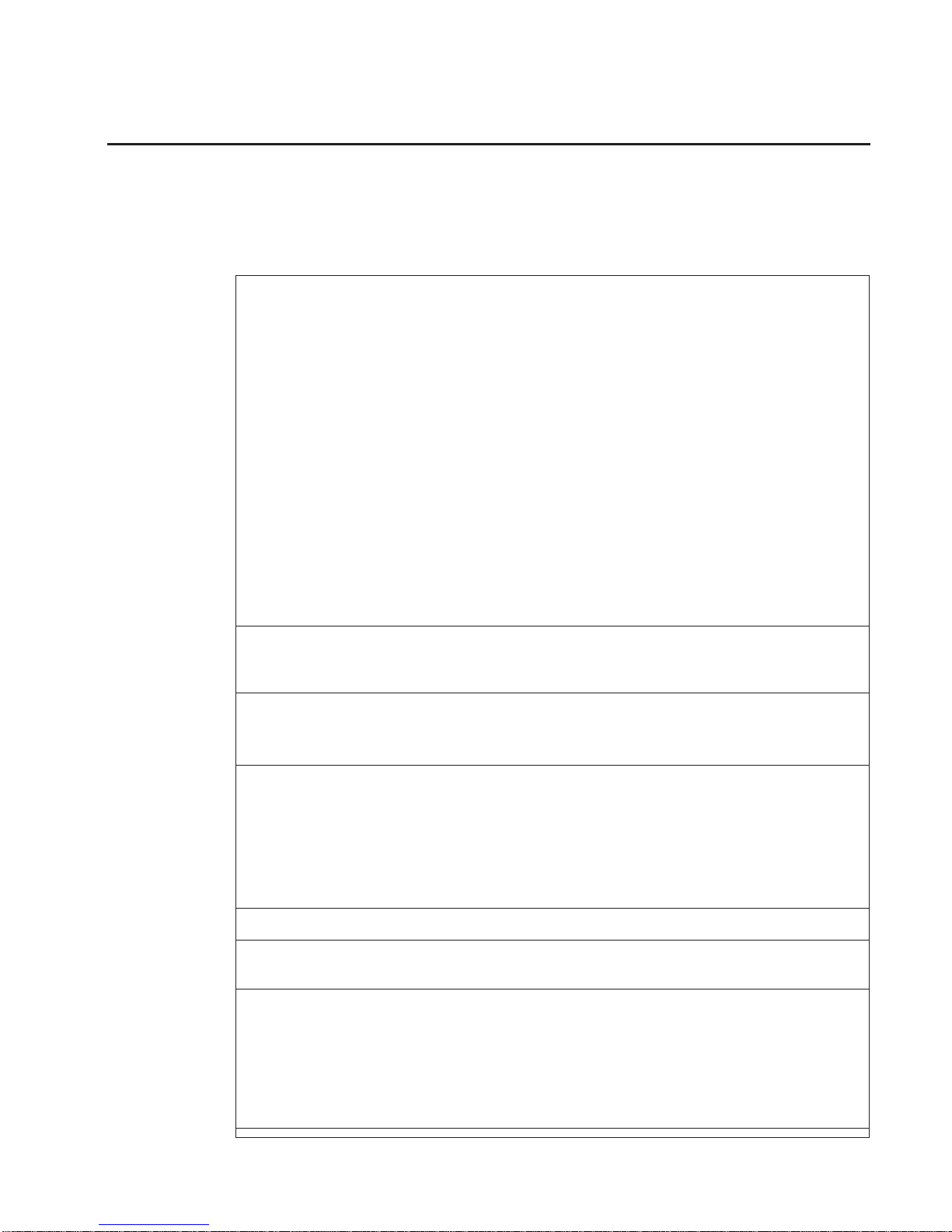
The green LEDs for the PCI-X adapter slots (viewed on the rear of the I/O subsystem)
are used to indicate the state of the PCI slot during removal and replacement of an
adapter.
PCI LED (Green) Indication PCI Slot Status Definition
Off Off Slot power is Off. It is safe to
remove or replace adapters.
On (not flashing) On Slot power is On. Do not
remove or replace adapters
Flashing slowly (one flash per
second)
Indicates slot has been
identified by the software. Do
not remove or replace adapters
at this time.
Flashing rapidly (six to eight
flashes per second)
Indicates slot is ready
removing or replacing an
adapter.
Chapter 1. Reference Information
17
Page 34

Model D20 Disk Drives
12 hot-plug disk-drive bays are provided. The bays are located behind the Model D20
front bezel. The Model D20 has from 18.2 GB to 1.7 terabytes of disk storage capacity.
The following disk drive sizes and speeds are available:
v 18.2 GB Ultra3 10K RPM 1 inch
v 36.4 GB Ultra3 10K RPM 1 inch
v 73.4 GB Ultra3 10K RPM 1 inch
v 146.8 GB Ultra3 10K RPM 1 inch
For an updated listing of hot-plug disk-drive sizes, contact your sales representative.
Model D20 Power
The Model D20 is standard with one power supply. If the customer wants redundant
power in their I/O subsystem, an optional power supply can be ordered. Either power
supply in a Model D20 configured with two power supplies is capable of providing the
necessary voltages and currents, independent of the other power supply. The left and
right power-supply output voltages are connected and monitored by the power
distribution board contained in the I/O subsystem.
The left and right power supplies are hot-pluggable and may be changed one at a time
while the system is operational. Each power supply is capable of converting available
110/220 V ac to the proper internal voltages used by the system components. The
internal voltage range is 5 volts system standby, 3.3 volts, 5 volts, 12 volts and -12
volts. When operating correctly, each supply will share the current load when powered
on. When in a fault state, the operable power supply will supply standby current to the
faulted supply for the DEVROS module. The following table describes power related
LED indicators that are available on the Model D20. The Operator Panel LED referred
to in the table below is on the front of the processor subsystem to which the I/O
subsystem is attached.
Status of LED Operator Panel LED (processor subsystem)
Off Power Source not connected
Blinking green LED System power source connected, but power is
not turned on
Blinking green LED, visibly begins to blink
faster after the power button has been pressed.
System power connected, the power on button
has been pressed and power-on initiated
Solid (not blinking) green LED, (There is
approximately a 30 second transition period
from the time the power on button is pressed to
the time the power LED is on solid.)
System power connected and turned on
18 Eserver pSeries 7311 Model D10 and Model D20 Service Guide
Page 35

Model D20 Cooling
Four blowers are mounted on the top of the I/O subsystem to provide cooling.
Attention: The four cooling blowers mounted on top of the Model D20 are hot-plug.
The one exception is when your subsystem has only one power supply either installed
or functioning, in which case you
must
shut down the system and subsystem. Failure to
do so will automatically shut down the system.
D20 Input/Output Ports
The connector ports on the rear of the Model D20 I/O subsystem are used to connect
the RIO cables, the SPCN cables, and the rack-beacon LED.
D20 I/O Subsystem Locations
The system uses physical location codes to provide mapping of the failing field
replaceable units. The location codes are produced by the processor subsystem’s
firmware and AIX. For information about how to read a location code, see the service
guide for the processor subsystem to which your I/O subsystem is connected.
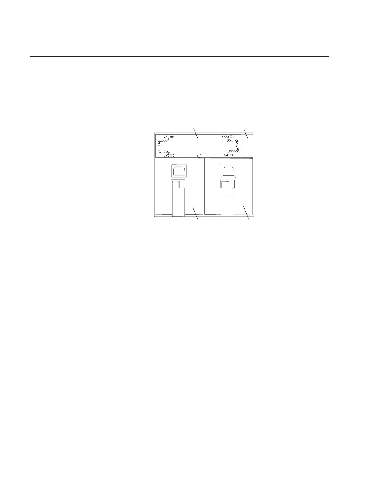
Model D20 Front View
1 Serial Number 3 Model D20 Front Bezel
2 Operator Panel 4 Disk Drives (maximum quantity
12 )
Chapter 1. Reference Information
19
Page 36

Model D20 Rear View
1 PCI-X Expansion Slot 1 9 Primary Power Supply
2 PCI-X Expansion Slot 2 10 Model D20 I/O Drawer
3 PCI-X Expansion Slot 3 11 Connector J11 (Not Used)
4 PCI-X Expansion Slot 4 12 Connector J14 (Not Used)
5 PCI-X Expansion Slot 5 13 Rear Serial Number Label
6 PCI-X Expansion Slot 6 14 Connector J15 System Power
Control Network Connector
(SPCN)
7 PCI-X Expansion Slot 7 15 Connector J16 System Power
Control Network Connector
(SPCN)
8 Redundant Power Supply
Receptacle
16 RIO Connectors
Upper Connector = 1
Lower Connector = 0
20 Eserver pSeries 7311 Model D10 and Model D20 Service Guide
Page 37

Model D20 Power Supply Locations
1
2
3
4
6
5
1 Power Supplies 4 Green AC Power LED
2 Amber Fault/Identify LED 5 Power Supply Filler
3 Green DC Good LED 6 Model D20 I/O Drawer
Chapter 1. Reference Information
21
Page 38

Model D20 Blower Locations
The following illustration identifies the I/O subsystem cooling blowers. Each blower has
a green power LED and an amber identify LED located on the front blower housing.
The green LED indicates that a blower has power and is operating properly. The amber
LED is in the identify state when blinking.
1 Green LED 4 Blower Connector
2 Amber LED 5 Hot-Plug Blower Assembly
3 Snap Button 6 Docking Connector
22 Eserver pSeries 7311 Model D10 and Model D20 Service Guide
Page 39

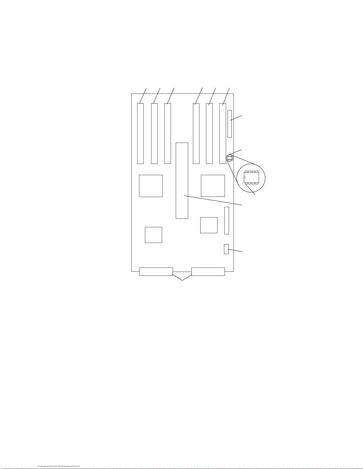
Model D20 I/O Backplane Locations
The following illustration of the I/O backplane identifies the primary connectors used in
your subsystem.
Note: Before replacing the I/O backplane, note the position of pin 1 on the VPD
module.
1 PCI-X Adapter Connector 1 11 Disk Drive Power Connector
2 PCI-X Adapter Connector 2 12 Cooling Blower Connector
3 PCI-X Adapter Connector 3 13 VPD Module
Attention: Note the location of Pin 1 before
removing.
4 PCI-X Adapter Connector 4 14 Redundant Power Supply Connector
5 PCI-X Adapter Connector 5 15 Primary Power Supply Connector
6 PCI-X Adapter Connector 6 16 Connector J11 (Not Used)
7 PCI-X Adapter Connector 7 17 Connector J14 (Not Used)
8 Operator Panel Connector 18 Connector J15 System Power Control Network
(SPCN) Connector
9 RIO Bus Adapter Connector 19 Connector J16 System Power Control Network
(SPCN) Connector
10 Disk Drive System Power Control Network
(SPCN) Connector
20 4-pin Connector, Rack Beacon Connector
Chapter 1. Reference Information
23
Page 40

Model D20 Reading the Operator Panel and I/O Backplane LEDs
The following illustration shows the component location on the operator panel
Number Component Name Component Description
1 Green Power LED Standby State - Blinking LED
(System connected to power source but not
powered on.)
Powered On - LED is turned on solid (not
blinking).
2 Amber Attention LED Normal State - LED is off.
3 Operator Panel
4 Snap Buttons
24 Eserver pSeries 7311 Model D10 and Model D20 Service Guide
Page 41

Model D20 SCSI IDs and Bay Locations
Index Bay Location Drive Name SCSI Bus ID
8 DB1 D01 Hot-Plug Disk Drive 8 - DB1
9 DB1 D02 Hot-Plug Disk Drive 9 - DB1
A DB1 D03 Hot-Plug Disk Drive A - DB1
B DB1 D04 Hot-Plug Disk Drive B - DB1
C DB1 D05 Hot-Plug Disk Drive C - DB1
D DB1 D06 Hot-Plug Disk Drive D - DB1
8 DB2 D07 Hot-Plug Disk Drive 8 - DB2
9 DB2 D08 Hot-Plug Disk Drive 9 - DB2
A DB2 D09 Hot-Plug Disk Drive A - DB2
B DB2 D10 Hot-Plug Disk Drive B - DB2
C DB2 D11 Hot-Plug Disk Drive C - DB2
D DB2 D12 Hot-Plug Disk Drive D - DB2
Note: The SCSI bus IDs are the recommended values and indicate how the IDs are
set when the system is shipped from the factory. Field installations might not
comply with these recommendations.
Chapter 1. Reference Information 25
Page 42

Cabling the Model D20 to a Model 6C4
The Model D20 subsystem can be installed in any location in a standard 19-inch EIA
rack. The cables that connect the subsystems allow some flexibility in drawer
placement. Up to two Model D20can be connected to a Model 6C4. Each I/O
subsystem is connected to the processor subsystem using a system power control
network (SPCN) cable loop and a remote I/O (RIO) cable loop. One SPCN cable loop is
needed to connect the I/O subsystems to one processor subsystem.
Before connecting the RIO-G and SPCN cables to the 7311, do the following:
1. Ensure that your Model 6C4 is running the latest level firmware. Refer to the
″Firmware Updates″ section of the ″Using the Service Processor″ chapter in the
pSeries 630 Model 6C4 and Model 6E4 Service Guide
, order number SA38-0604
for information on checking or upgrading the firmware level of your Model 6C4.
2. After ensuring that your firmware is at the latest level, turn the power off and
disconnect the Model 6C4 power cables from the power source.
3. Attach the RIO-G and SPCN cables. For cabling diagrams see “RIO (Remote Input
Output) Cabling” on page 27.
4. After connecting the RIO-G and SPCN cables from the 7311 to your system,
reconnect the system’s power cables to the power source and refer to “Starting the
System” on page 55.
5. Run system verification, refer to the ″Verifying the Hardware″ chapter located in the
pSeries 630 Model 6C4 and Model 6E4 Installation Guide
, order number
SA38-0604.
Your Model 6C4 is expandable when connected up to two 7311 I/O drawers. Each 7311
can contain up to 7 I/O PCI adapter slots, and two 6 pack disk drive (DASD) bays.
26 Eserver pSeries 7311 Model D10 and Model D20 Service Guide
Page 43

RIO (Remote Input Output) Cabling
The following rules apply to RIO cable connections:
Notes:
1. To connect to a 7311 you will be using the RIO-G (Remote Input Output) and SPCN
(System Power Control Network) connectors and cables. The RIO-G and SPCN
cables provide two functions, remote data bus connection and power control.
2. The I/O drawers must be connected in a loop fashion for both the RIO-G and SPCN
cables. The loop connection provides redundant paths so that if a failure occurs in
part of a cable, the system will continue to operate. If a failure does occur, a
warning message is displayed on the system console; however, the system does
continue to operate. See the following illustrations for possible cabling
configurations.
To connect the RIO-G cables to the back of the Model 6C4, do the following:
1. Locate the RIO-G cable support bracket.
2. Using two M3 x 6 retaining screws, secure the RIO-G cable support bracket to the
rear of the Model 6C4 chassis. See the following illustration.
1 Model 6C4
2 RIO-G Cable Support Bracket
3 M3 x 6 Retaining Screws (Quantity 2)
3. Pull the sliding portion of the RIO-G cable support bracket back from the Model 6C4
chassis. The sliding portion of the cable support bracket will stop before being fully
separated.
4. Align the RIO-G cable connector with the bottom of the sliding portion of the RIO-G
cable support bracket.
Chapter 1. Reference Information 27
Page 44

5. Lift the RIO-G cable and cable connector into the bottom of the RIO-G cable
support bracket.
1 Model 6C4
2 RIO-G Cable Support Bracket
3 Slide Portion of RIO-G Cable Support Bracket
4 RIO-G Connector Support Lever
6. Pull the RIO-G connector back until the connector is seated against the support
hook.
7. Push the RIO-G connector forward, ensuring that the RIO-G connector lever slides
over the top of the connector hooks.
8. Slowly push the assembly toward the chassis.
9. Secure with the captive thumbscrew, the RIO-G connector and slide portion of the
RIO-G support bracket to the back of the Model 6C4 chassis.
1 Captive Thumbscrews
2 RIO-G Cable and Connector
3 RIO-G Connector Support Lever
28 Eserver pSeries 7311 Model D10 and Model D20 Service Guide
Page 45

Model 6C4 Attached to One I/O Drawer:
1 Model 6C4 3 RIO-G 0 to RIO-G 0 Cable
2 7311 4 RIO-G 1 to RIO-G 1 Cable
Model 6C4 Attached to Two I/O Drawers:
1 Model 6C4 4 RIO-G 0 to RIO-G 0 Cable
2 7311 I/O Drawer 5 RIO-G 1 to RIO-G 1 Cable
3 7311 I/O Drawer 6 RIO-G 1 to RIO-G 0 Cable
Chapter 1. Reference Information
29
Page 46

SPCN (System Power Control Network) Cabling
The following figures provide cabling examples for all valid cabling configurations.
Match your configuration to the correct figure and connect your SPCN cables as shown.
Model 6C4 Attached to One I/O Drawer:
1 Model 6C4 3 SPCN 2 to SPCN 2 Cable
2 7311 4 SPCN 1 to SPCN 1 Cable
30 Eserver pSeries 7311 Model D10 and Model D20 Service Guide
Page 47

Model 6C4 Attached to Two I/O Drawers:
1 Model 6C4 4 SPCN 1 to SPCN 1 Cable
2 7311 I/O Drawer 5 SPCN 2 to SPCN 2 Cable
3 7311 I/O Drawer 6 SPCN 2 to SPCN 1 Cable
Chapter 1. Reference Information
31
Page 48

Model D20 Internal Cabling
1 Cooling Blowers (Quantity 4) 6 Disk Drive Power Connector
2 Operator Panel 7 Disk Drive SPCN Connector
3 Disk Drive Backplanes 8 Disk Drive Power/Signal Cable
53P0416
4 Cooling Blower Cable
53P0419
9 Operator Panel Connector
5 Cooling Blower Connector 10 Operator Panel Cable
53P0414
32 Eserver pSeries 7311 Model D10 and Model D20 Service Guide
Page 49

Model D20 Location Codes
This system (processor subsystem and attached I/O subsystems) uses physical location
codes in conjunction with AIX location codes to provide mapping of a failing field
replaceable units. The location codes are produced by the processor subsystem’s
firmware and AIX. For information about how to read a location code, see the service
guide for the processor subsystem to which your I/O subsystem is connected.
AIX and Physical Location Code Table
This section covers the AIX and Physical Location Code tables for the Model D20 I/O
subsystem.
The tables in this section contain the location codes for I/O subsystems when they are
attached to the system unit. In the tables, the location code for the I/O subsystem
number is represented by
dd
. The first time that an installed system is powered on, the
I/O subsystems are numbered. For example, if a system is first powered on with two I/O
subsystems connected, then the
dd
value for the connected I/O subsystems should be
numbered from 2 and 3.
Note: If the system was powered on with I/O subsystems connected before delivery to
the customer, the I/O subsystem location codes for the drawers connected at
that time are already assigned.
If at a later time, an I/O subsystem is removed from the system and a different I/O
subsystem is substituted, the substitute is assigned the next higher number available for
its value of
dd
, which, in the earlier example, is 4. If the original I/O subsystem is
reinstalled in the system configuration, the system uses the original
dd
value for the I/O
subsystem.
To keep the system from renumbering the I/O drawer when an I/O backplane is
replaced, the VPD module from the old I/O backplane must be moved over to the new
I/O backplane.
The following diagram defines each part of a location code.
Ux.dd-xx-yy
||||
||||
|||yyThis code is used for the next component (yy, yy, yy, ...)
| | xx This code is used for the next component (Px, Fx, Vx, ...)
| dd This code is the location code for the I/O drawer (2 to 63)
Ux This code normally identifies the rack in which a drawer is installed.
The x will always be zero (0) for this system.
Chapter 1. Reference Information 33
Page 50

Model D20Location Code Table
The following table lists the location codes for a model D20 I/O subsystem. The location
code for the I/O subsystem connected to a system unit is U0.
dd
(whereddcan be any
number from 2 through 63).
FRU Name Physical Location Code
Model D20 I/O Drawer U0.
dd(dd
= any number from 2 through 63)
Rack frame U0
I/O drawer backplane U0.
dd
-P1
I/O subsystem drawer U0.
dd
RIO Bus Adapter
RIO bus adapter U0.
dd
-P1.1
RIO port 1 upper connector U0.
dd
-P1.1/Q1
RIO port 1 cable U0.
dd
-P1.1/Q1#
RIO port 0 lower connector U0.
dd
-P1.1/Q2
RIO port 0 cable U0.
dd
-P1.1/Q2#
PCI Bus Controller
PCI bus controller PHB0 U0.
dd
-P1
PCI to PCI bridge EADS-X U0.
dd
-P1
PCI Bus Controller PHB2
PCI bus controller PHB2 U0.
dd
-P1
PCI to PCI bridge EADS-X U0.
dd
-P1
Pluggable Adapter Slots
PCI slot 1 U0.
dd
-P1/I1
PCI card in slot 1 U0.
dd
-P1-I1
PCI slot 2 U0.
dd
-P1/I2
PCI card in slot 2 U0.
dd
-P1-I2
PCI slot 3 U0.
dd
-P1/I3
PCI card in slot 3 U0.
dd
-P1-I3
PCI slot 4 U0.
dd
-P1/I4
PCI card in slot 4 U0.
dd
-P1-I4
PCI slot 5 U0.
dd
-P1/I5
PCI card in slot 5 U0.
dd
-P1/I5
PCI slot 6 U0.
dd
-P1/I6
PCI card in slot 6 U0.
dd
-P1/I6
PCI slot 7 U0.
dd
-P1/I7
PCI card in slot 7 U0.
dd
-P1/I7
Power Supply
Power supply 1 (no internal blower) U0.
dd
-V1
Power supply 2 (no internal blower) U0.
dd
-V2
34 Eserver pSeries 7311 Model D10 and Model D20 Service Guide
Page 51

FRU Name Physical Location Code
Cooling Blowers
Cooling blower 1 U0.
dd
-F1
Cooling blower 2 U0.
dd
-F2
Cooling blower 3 U0.
dd
-F3
Cooling blower 4 U0.
dd
-F4
SPCN Connectors
SPCN connector 1 U0.
dd
-P1/Q3
SPCN connector 2 U0.
dd
-P1/Q4
SPCN connector 3 U0.
dd
-P1/Q5
SPCN connector 4 U0.
dd
-P1/Q6
Rack Indicator
Rack beacon (4–pin) U0.
dd
-P1/Q7
Operator Panel
Operator panel U0.
dd
-L1
Temperature Sensor
Temperature sensor (on operator panel) U0.
dd
-L1
Disk Drives Backplanes
Disk drives backplane 1 U0.
dd
-P3
Disk drives backplane 2 U0.
dd
-P4
Disk Drive Locations
Hot-swap disk drive bay 1 U0.
dd
-P1-Ix/Zn-A8
Hot-swap disk drive bay 2 U0.
dd
-P1-Ix/Zn-A9
Hot-swap disk drive bay 3 U0.
dd
-P1-Ix/Zn-AA
Hot-swap disk drive bay 4 U0.
dd
-P1-Ix/Zn-AB
Hot-swap disk drive bay 5 U0.
dd
-P1-Ix/Zn-AC
Hot-swap disk drive bay 6 U0.
dd
-P1-Ix/Zn-AD
Hot-swap disk drive bay 7 U0.
dd
-P1-Iy/Zn-A8
Hot-swap disk drive bay 8 U0.
dd
-P1-Iy/Zn-A9
Hot-swap disk drive bay 9 U0.
dd
-P1-Iy/Zn-AA
Hot-swap disk drive bay 10 U0.
dd
-P1-Iy/Zn-AB
Hot-swap disk drive bay 11 U0.
dd
-P1-Iy/Zn-AC
Hot-swap disk drive bay 12 U0.
dd
-P1-Iy/Zn-AD
SCSI
SES0 U0.
dd
-P1-Ix/Zn-AF
SES1 U0.
dd
-P1-Iy/Zn-AF
Chapter 1. Reference Information
35
Page 52

Powering the System On and Off
Power for the I/O subsystems is controlled by the attached processor subsystem and
the System Power Control Network (SPCN).
Power-On Self-Test
After power is turned on and before the operating system is loaded, the system does a
power-on self-test (POST). The RIO loop that connects the I/O subsystems to the
system unit is tested. Tests are also performed on the installed adapters and devices in
the I/O subsystems. If an error occurs during the POST, an error code is displayed on
the system operator panel LCD that indicates which part is failing and which subsystem
contains the error.
36 Eserver pSeries 7311 Model D10 and Model D20 Service Guide
Page 53
Specifications
This section contains system specifications for both the 7311 Model D10 I/O
Subsystem, and the 7311 Model D20 I/O Subsystem
Model D10 Specifications
Dimensions 7311-D10 Two 7311-D10s with
Enclosure
Height 170 mm (6.6 in) 178 mm (7.0 in)
Width 220 mm (8.7 in) 445 mm (17.5 in)
Depth 711 mm (28.0 in) 711 mm (28.0 in)
Weight 16.8 kg (37 lbs) 39.1 kg (86 lbs)
Electrical
Power source loading for two 7311-D10 (max.) 0.21 kVA
Voltage range 200 to 240 V ac, (dc not supported)
Frequency 50 or 60 Hz
Thermal output (typical) 461 Btu/hr
Thermal output (max.) 683 Btu/hr
Power requirements (typical) 135 watts
Power requirements for two 7311-D10 (max.) 200 watts
Power factor 0.91
Inrush current² 64 amps
Maximum altitude
3, 4
3048 m (10000 ft.)
Temperature Requirements³ Operating
10 to 38°C
50 to 100°F)
Non-Operating
1 to 60°C
(34 to 140°F)
Storage
1 to 60°C
(34 to 140°F)
Humidity Requirements⁴ Operating Non-Operating Storage
(Noncondensing) 8 to 80% 8 to 80% 8 to 80%
Wet Bulb 23°C (73°F) 27°C (81°F) 29°C (84°F)
Noise Emissions
1, 4
Operating Idle
L
WAd
, one 7311-D10
L
WAd
, two 7311-D10
L
WAd
, four 7311-D10
5.6 bels
5.9 bels
6.2 bels
5.6 bels
5.9 bels
6.2 bels
<L
pA>m
, one 7311-D10
<L
pA>m
, two 7311-D10
<L
pA>m
, four 7311-D10
40 dBA
43 dBA
46 dBA
40 dBA
43 dBA
46 dBA
Install/Air Flow: Maintaining service clearance allows proper air flow.
Service Clearances See 7014 Model T00 and T42 Rack for T00 or T42 rack
service clearances.
1. See page 202 for definitions of noise emissions positions. See noise emissions note 4.
2. Inrush currents occur only at initial application of power, no inrush occurs during normal
power off-on cycle.
3. The upper limit of the dry bulb temperature must be derated 1°C per 137 m (450 ft.) above
915 m (3000 ft.).
4. The upper limit of the wet bulb temperature must be derated 1°C per 274 m (900 ft. ) above
305 m (1000 ft.).
Chapter 1. Reference Information
37
Page 54

Model D20 Specifications
Dimensions
Height 178 mm (7.0 in)
Width 445 mm (17.5 in)
Depth 610 mm (24.0 in)
Maximum Weight 45.9kg (101 lbs)
Electrical
Power source loading
(max.)
0.358 kVA
Voltage range 100 to 240 V ac, V dc not supported
Frequency 50 or 60 Hz
Thermal output (typical) 774 Btu/hr
Thermal output (max.) 1161 Btu/hr
Power requirements
(typical)
227 watts
Power requirements for
two 7311-D20 (max.)
340 watts
Power factor 0.91
Inrush current² 60 amps
Maximum altitude
3, 4
3048 m (10,000 ft.)
Temperature
Requirements³
Operating
5 to 35°C
41 to 95°F)
Non-Operating
1 to 43°C
(34 to 109°F)
Storage
1 to 60°C
(34 to 140°F)
Humidity
Requirements⁴
Operating Non-Operating Storage
(Noncondensing) 8 to 80% 8 to 80% 5 to 80%
Wet Bulb 23°C (73°F) 27°C (81°F) 29°C (84°F)
Noise Emissions
1, 5
Operating Idle
L
WAd
6.1 bels 6.0 bels
<L
pA>m
44 dBA 43 dBA
Install/Air Flow Maintenance of service clearance will allow proper air flow.
Service Clearances See 7014 Model T00 and T42 Rack for T00 or T42 rack service
clearances.
1. See 202 for definitions of noise emissions positions. See noise emissions note 4.
2. Inrush currents occur only at initial application of power, no inrush occurs during normal
power off-on cycle.
3. The upper limit of the dry bulb temperature must be derated 1 degree C per 137 m (450 ft.)
above 915 m (3000 ft.).
4. The upper limit of the wet bulb temperature must be derated 1 degree C per 274 m (900 ft. )
above 305 m (1000 ft.).
38 Eserver pSeries 7311 Model D10 and Model D20 Service Guide
Page 55

External AC Power Cables
To avoid electrical shock, a power cable with a grounded attachment plug is provided.
Use only properly grounded outlets.
Power cables used in the United States and Canada are listed by Underwriter’s
Laboratories (UL) and certified by the Canadian Standards Association (CSA). These
power cords consist of the following:
v Electrical cables, Type SVT or SJT.
v Attachment plugs complying with National Electrical Manufacturers Association
(NEMA) 5-15P, that is:
″For 115 V operation (Model D20 only), use a UL listed cable set consisting of a
minimum 18 AWG, Type SVT or SJT three-conductor cord a maximum of 15 feet in
length and a parallel blade, grounding type attachment plug rated at 15 A, 125 V.″
″For 230 V operation in the United States use a UL listed cable set consisting of a
minimum 18 AWG, Type SVT or SJT three-conductor cable a maximum of 15 feet in
length, and a tandem blade, grounding type attachment plug rated at 15 A, 250 V.″
v Appliance couplers complying with International Electrotechnical Commission (IEC)
Standard 320, Sheet C13.
Power cables used in other countries consist of the following:
v Electrical cables, Type HD21.
v Attachment plugs approved by the appropriate testing organization for the specific
countries where they are used.
″For units set at 230 V (outside of U.S.): use a cable set consisting of a minimum 18
AWG cable and grounding type attachment plug rated 15 A, 250 V. The cable set
should have the appropriate safety approvals for the country in which the equipment will
be installed and should be marked `HAR’.″
Refer to Chapter 9, “Parts Information”, on page 179 to find the power cables that are
available.
Chapter 1. Reference Information 39
Page 56

Service Inspection Guide
Perform a service inspection on the system (processor subsystem and connected I/O
subsystems) when:
v The system is inspected for a maintenance agreement.
v Service is requested and service has not recently been performed.
v An alterations and attachments review is performed.
v Changes have been made to the equipment that may affect the safe operation of the
equipment.
v External devices with their own power cables have those cables attached.
If the inspection indicates an unacceptable safety condition, the condition must be
corrected before anyone can service the machine.
Note: The owner of the system is responsible to correct any unsafe conditions.
Perform the following checks:
1. Check the covers for sharp edges and for damage or alterations that expose the
internal parts of the system.
2. Check the covers for proper fit to the system. They should be in place and secure.
3. Gently rock the system from side to side to determine if it is steady.
4. Set the power button of the system to Off.
5. Remove the covers.
6. Check for alterations or attachments. If there are any, check for obvious safety
hazards, such as broken wires, sharp edges, or broken insulation.
7. Check the internal cables for damage.
8. Check for dirt, water, and any other contamination within the system.
9. Check the voltage label on the back of the system to ensure that it matches the
voltage at the outlet.
10. Check the external power cable for damage.
11. With the external power cable connected to the system, check for 0.1 ohm or less
resistance between the ground lug on the external power cable plug and the metal
frame.
12. Perform the following checks on each device that has its own power cables:
a. Check for damage to the power cable.
b. Check for the correctly grounded power cable.
c. With the external power cable connected to the device, check for 0.1 ohm or
less resistance between the ground lug on the external power cable plug and
the metal frame of the device.
13. Install the covers.
40 Eserver pSeries 7311 Model D10 and Model D20 Service Guide
Page 57

Chapter 2. Diagnostics Overview
The system uses an integrated set of software diagnostic procedures to help isolate
failing components and system maintenance. This book, along with the
RS/6000
Eserver
pSeries Diagnostic Information for Multiple Bus Systems
, is the basis of the
diagnostic procedures. Refer to the system service guide when running diagnostic on
your I/O subsystem.
Power and Attention LEDs
The Power and Attention LEDs provide a means to identify failing components in your
subsystem. When a failing component is detected in your system, the system’s
Attention LED is turned on.
Component LEDs
To further help you identify the failing component, all system components have
individual LEDs that indicate a failure when lit. The LEDs are either on the component
itself or on the carrier of the component (memory card, fan, memory module, CPU).
The LEDs are either green or amber in color. A lit green LED indicates that the system
or component is receiving power. A lit amber LED indicates the system or component
has a failure.
Resetting the LEDs
To reset the LEDs, do the following:
1. Replace the failing component with the new component.
2. Log in as root user.
3. At the command line, type diag.
4. Select Task Selection.
5. Select Log Repair Action.
6. Select the device that was repaired. (If the device is not listed, select sysplanar0.)
Checkpoints
The system uses various types of checkpoints, error codes, and SRNs, which are
referred to throughout your system’s service guide. These codes can appear in the
service processor boot progress log, the AIX error log, and the operator panel display.
Understanding the definition and relationships of these codes is important to the service
personnel who are installing or maintaining the system.
Service Request Numbers (SRNs) are listed in the
RS/6000
Eserver
pSeries
Diagnostic Information for Multiple Bus Systems
, order number SA38-0509.
41
Page 58

FRU Isolation
For a list of error codes and recommended actions for each code, see your system’s
service guide. These actions can refer to Chapter 9, “Parts Information”, on page 179,
Chapter 3, “Maintenance Analysis Procedures (MAPs)”, on page 43, or provide
informational message and directions. If a replacement part is indicated, direct
reference is made to the part name. The respective AIX and physical location codes are
listed for each occurrence as required. For a list of locations codes, see your system’s
service guide.
42 Eserver pSeries 7311 Model D10 and Model D20 Service Guide
Page 59

Chapter 3. Maintenance Analysis Procedures (MAPs)
The maintenance analysis procedures (MAPs) provide the service representative a
step-by-step procedure to analyze a problem with the system and I/O subsystem
hardware. Be prepared to record code numbers and other data while using the MAPs.
Because the Model D10 and Model D20 are subsystems, refer to your system’s service
guide. The system service guide contains all of the MAPs needed for servicing the
Model D10 and Model D20 I/O subsystems.
43
Page 60

44 Eserver pSeries 7311 Model D10 and Model D20 Service Guide
Page 61

Chapter 4. Checkpoints
Checkpoints display on the system operator panel and the virtual terminal while the
system unit is powering on and going through the initial program load (IPL). See the
system’s service guide for descriptive information and a complete listing of all
checkpoints used by the Model D10 and Model D20 I/O subsystems.
45
Page 62

46 Eserver pSeries 7311 Model D10 and Model D20 Service Guide
Page 63

Chapter 5. Error Code to FRU Index
The Error Code to FRU Index lists fault symptoms and possible causes. The most likely
cause is listed first. Use this index to help you decide which FRUs to replace when
servicing the Model D10Model D20 I/O subsystem. See your system’s service guide for
more information and a complete listing of all error codes and FRUs used by the Model
D10 and Model D20 I/O subsystem.
47
Page 64

48 Eserver pSeries 7311 Model D10 and Model D20 Service Guide
Page 65

Chapter 6. Using the Service Processor
The service processor is in the processor subsystem to which your I/O subsystem is
connected and runs on its own power boundary. The service processor continually
monitors hardware attributes and the environmental conditions within the system and
connected I/O subsystems. The service processor is controlled by firmware and does
not require the operating system to be operational to perform its tasks.
The service processor menus allow you to configure service processor options, as well
as enable and disable functions.
Service processor menus are available using an ASCII terminal or an HMC virtual
terminal window when OK is displayed on the operator panel or when the service
processor has detected a system problem (such as a surveillance failure).
For more information about the service processor for the system to which your I/O
subsystem is connected, see the system unit’s service guide.
49
Page 66

50 Eserver pSeries 7311 Model D10 and Model D20 Service Guide
Page 67

Chapter 7. Using System Management Services
Use the system management services menus to view information about the processor
subsystem to which the I/O subsystem is connected. For more information about the
service processor, see the service guide for the attached system.
51
Page 68

52 Eserver pSeries 7311 Model D10 and Model D20 Service Guide
Page 69

Chapter 8. Removal and Replacement Procedures
Before performing any of the removal or replacement procedures in this chapter, read
the following danger and caution notices.
Safety Considerations
Observe the following safety precautions anytime you work with these I/O subsystems.
For the I/O subsystem you are about to setup or service:
v The ac power interface connector is considered the main power disconnect device.
v The I/O subsystems have independent redundant power supply capabilities, meaning
that each unit might be configured to have two power supplies running
simultaneously in the same I/O subsystem. When instructed to disconnect the power
source, ensure that all power cables that run to each serviced subsystem are
disconnected from the power distribution bus.
DANGER
An electrical outlet that is not correctly wired could place hazardous voltage
on metal parts of the system or the devices that attach to the system. It is the
responsibility of the customer to ensure that the outlet is correctly wired and
grounded to prevent an electrical shock.
Before installing or removing signal cables, ensure that the power cables for
the system unit and all attached devices are unplugged.
When adding or removing any additional devices to or from the system,
ensure that the power cables for those devices are unplugged before the
signal cables are connected. If possible, disconnect all power cables from the
existing system before you add a device.
Use one hand, when possible, to connect or disconnect signal cables to
prevent a possible shock from touching two surfaces with different electrical
potentials.
During an electrical storm, do not connect cables for display stations, printers,
telephones, or station protectors for communications lines.
D05
53
Page 70

CAUTION:
This product is equipped with a three-wire power cable and plug for the user’s
safety. Use this power cable with a properly grounded electrical outlet to avoid
electrical shock.
C01
CAUTION:
This unit has more than one power supply cord. To reduce the risk of electrical
shock, disconnect two power supply cords before servicing.
C21
Handling Static-Sensitive Devices
Attention: Electronic boards and disk drives are sensitive to static electricity
discharge. These devices are wrapped in antistatic bags to prevent this damage.
Take the following precautions:
v If you have an antistatic wrist strap available, use it while handling the device.
v Do not remove the device from the antistatic bag until you are ready to install the
device in the system.
v With the device still in its antistatic bag, touch it to a metal frame of the system.
v Grasp cards and boards by the edges. Hold drives by the frame. Avoid touching the
solder joints or pins.
v If you need to lay the device down while it is out of the antistatic bag, lay it on the
antistatic bag. Before picking it up again, touch the antistatic bag and the metal
frame of the system at the same time.
v Handle the devices carefully to prevent permanent damage.
54 Eserver pSeries 7311 Model D10 and Model D20 Service Guide
Page 71

Stopping the System
Attention: When shutting down your system to perform service procedures, shut
down all applications first and then shut down the operating system. The system power
turns off and the system goes into standby mode when the operating system is shut
down. Before removing power from the system, ensure that the shutdown process is
complete. Failure to do so can result in the loss of data. Some procedures do not
require the system to be stopped. The removal and replacement procedures in this
chapter will direct you here if stopping the system is required.
1. Log in to the system as root user.
2. Have the system administrator stop all applications that are running on the system.
3. At a command line, type shutdown to stop the operating system.
4. After you shut down the operating system, set the power switches of any attached
devices to Off.
Starting the System
To power on the system, perform the following steps in sequence.
1. Open the rack front door.
2. Connect the power sources to the I/O subsystem and the connected processor
subsystem.
Prior to pushing the power button on the system operator panel, observe the
following:
v The power led is slowly blinking.
v An OK prompt is visible in the operator panel display.
3. Press the power-on button on the operator panel.
After pushing the power button located on the operator panel, observe the following:
a. The power led begins to blink visibly faster.
b. The system cooling blowers are activated and can be heard revving up to
operating speed.
Note: There is approximately a 30 second transition period between the time
the power button is pressed and the power LED remains on solid (no
longer blinking).
c. The power led stays on solid and progress indicators, also referred to as
checkpoints
, are visible on the operator panel display.
Chapter 8. Removal and Replacement Procedures 55
Page 72

7311 Model D10 I/O Subsystem Removal and Replacement Procedures
The following procedures cover the removal and replacement of the 7311 Model D10
I/O Subsystem.
Note: Before performing any of the removal or replacement procedures in this chapter,
read the danger and caution notices on “Safety Considerations” on page 53.
Model D10 FRU Replacement Procedure List
Field Replaceable Unit
(FRU)
FRU Procedure Name and Page Location
Adapters “D10 PCI Adapters” on page 61
Bezel “D10 Front Bezel” on page 58
Cover “D10 Covers” on page 59
Blower “D10 Fan” on page 120
I/O Backplane “D10 I/O Backplane Assembly” on page 122
Operating Position “D10 Operating Position” on page 57
Power Supplies “D10 Power Supply” on page 123
RIO Bus Adapter “D10 RIO Bus Adapter” on page 121
Service Position “D10 Service Position” on page 57
Starting the System “Starting the System” on page 55
Static-Sensitive Devices “Handling Static-Sensitive Devices” on page 54
Stopping the System “Stopping the System” on page 55
56 Eserver pSeries 7311 Model D10 and Model D20 Service Guide
Page 73

D10 Service Position
To perform a removal or replacement procedure that requires access to the inside of
the I/O subsystem, the subsystem must be removed from the rack and placed on a
stable work surface. To put the drawer into the service position, do the following:
1. Shut down the system unit to which the I/O subsystem is connected.
2. From the rear of the rack, disconnect the I/O subsystem’s power cables from the
power distribution bus.
3. Remove the retaining screws located on the rear of the I/O subsystem drawer.
4. Label and disconnect all of the cables connected to the rear of the I/O subsystem.
5. From the rear of the rack, pull the I/O subsystem straight back until the subsystem
stops.
6. To allow the subsystem to move further to the rear, press the stop latch on the side
of the enclosure.
7. Support the I/O subsystem as you pull it toward the rear of the rack.
8. When the I/O subsystem is out of the rack, place it on a stable work surface.
D10 Operating Position
To return the subsystem to the operating position, do the following:
1. From the rear of the rack, insert the I/O subsystem into the position from which it
was removed. The end of the I/O subsystem that has the power supplies goes
toward the front of the rack.
2. Support the I/O subsystem as you push it toward the front of the rack.
3. Install the retaining screws in the rear of the I/O subsystem drawer.
4. Reconnect the cables to the rear of the I/O subsystem.
5. Reconnect the power cables.
6. Restart the system.
Chapter 8. Removal and Replacement Procedures 57
Page 74

D10 Front Bezel
Before performing the following procedure, read the “Safety Notices” on page vii.
Removal
To remove the front bezel, do the following:
1. Open the front rack door.
2. Simultaneously press in both bezel-release tabs.
3. Pivoting the bezel from the top, swing the top forward.
4. Pull the bottom of the bezel up, then away from the subsystem chassis. This
releases the two tab hooks located on the bottom of the I/O subsystem chassis.
Front Bezel Replacement
To replace the front bezel, do the following:
1. Open the front rack door.
2. Insert the two tabs located on the bottom edge of the bezel into their locking hooks,
located on the chassis.
3. Pivot the front bezel up toward the top of the chassis.
4. Align the release tabs to the matching slots located on the front of the subsystem
chassis.
5. Gently push the tabs into the slots until the bezel seats against the front of the
subsystem.
6. If the subsystem is not completely in the operating position, push the subsystem
back into the operating position as described in “D10 Operating Position” on
page 57.
7. Close the rack door.
58 Eserver pSeries 7311 Model D10 and Model D20 Service Guide
Page 75

D10 Covers
Before performing the following procedure, read the “Safety Considerations” on
page 53.
Service Access Cover Removal
To remove the service access cover, do the following:
1. Perform the procedure to put the I/O subsystem into the service position as
described in “D10 Service Position” on page 57.
2. Loosen the two captive thumbscrews located on the rear of the cover.
3. From the rear of the I/O subsystem, lift the cover and slide it backwards until the
front disengages. Lift the cover off the I/O subsystem drawer.
1
2
1 Service access cover 2 Thumbscrews
Chapter 8. Removal and Replacement Procedures
59
Page 76

Service Access Cover Replacement
To replace the service access cover, do the following:
1. Position the cover over the rear of the I/O subsystem.
2. Align the service access cover with the I/O subsystem so that the front portion of
the cover engages with the front part of the I/O subsystem chassis. The flanges on
the left and right sides of the cover should be on the outside of the I/O subsystem
chassis.
3. Hold the service access cover down and slide it forward toward the front of the I/O
subsystem. The front edge of the service access cover engages the front portion of
the I/O subsystem.
4. Push in to engage and then tighten the thumbscrews located on the rear of the
cover.
1
2
1 Service access cover 2 Thumbscrews
60 Eserver pSeries 7311 Model D10 and Model D20 Service Guide
Page 77

D10 PCI Adapters
Most PCI adapters can be removed and replaced, or installed in the system without
turning off the power to the entire system. These adapters are referred to as
hot-pluggable PCI adapters
. Some adapters are not hot-pluggable and power must be
removed from the system for adapter removal, replacement, or installation. Though
some adapters are not hot-pluggable, they must still be installed in the cassette.
Note: An adapter or an adapter blank filler must be installed into the PCI adapter
cassette assembly before it is reinstalled in a system unit or an I/O drawer.
Before you remove or replace an adapter, determine if the PCI adapter you are working
with is hot-pluggable. See the
PCI Adapter Placement Reference
, order number
SA38-0538.
If you are removing a PCI adapter that is:
v Not hot-pluggable, go to “Removing a Non-Hot-Pluggable PCI Adapter”.
v Hot-pluggable, go to “Hot-Pluggable PCI Adapter” on page 63.
Removing a Non-Hot-Pluggable PCI Adapter
To remove a non-hot-pluggable adapter, do the following:
1. Turn off power and remove the power from the system as described in “Stopping
the System” on page 55.
2. Determine the slot from which you are removing the adapter.
3. Disconnect any cables that are connected to the adapter being removed.
4. Press the center of the handle of the PCI card cassette to release the latch, then
lower the handle completely.
5. When the handle is completely lowered, push the gray locking cross bar.
6. Carefully pull the PCI card cassette straight out from the I/O subsystem as shown
in the following illustration. Take care not to pull EMC gaskets from neighboring
cassettes.
1 I/O Subsystem 2 PCI adapter Cassette
7. If you are installing another adapter in this slot, follow the instructions given in
“Replacing a Non-Hot-Pluggable PCI Adapter” on page 62.
Chapter 8. Removal and Replacement Procedures 61
Page 78

8. If you are not installing another adapter in this slot, install a blank PCI adapter
cassette into the slot.
9. Connect power to the system and turn the power on.
10. Return the system to normal operations.
Replacing a Non-Hot-Pluggable PCI Adapter
Replace the adapter using the following procedure:
Note: Because the adapter you are installing is not hot-pluggable, shut down the
system and remove power before performing this procedure.
1. Press the center of the handle of the PCI card cassette to release the latch, then
lower the handle completely.
2. When the handle is completely lowered, push the gray locking cross bar.
3. Hold the assembly straight on and level with the slot.
4. Align the bottom edge of the PCI cassette cover with the PCI card guide rail on the
I/O backplane.
Note: If there is a cassette to the left of the one you are installing, align the ridge
on the cover with the ″tick″ in the notch of the neighboring cassette.
5. Slide the cassette partially into the guide.
6. Ensure the dovetail on the top track aligns with its mating component(s) on both
sides.
7. When the cassette is fully inserted, prepare to activate the handle by lowering the
gray locking bar. Lift the handle all the way up until you hear a click. The PCI Card
should be completely seated.
Note: To enable proper insertion of the adapter, some minor forward or backward
movement of the PCI adapter cassette might be necessary.
8. Set the color slide to blue.
9. Connect power to the system and turn the power on as described in “Starting the
System” on page 55.
10. Ensure that the adapter is configured when the system completes the boot
process.
62 Eserver pSeries 7311 Model D10 and Model D20 Service Guide
Page 79

Hot-Pluggable PCI Adapter
Before performing the following procedure, read “Safety Notices” on page vii.
The following hot-plug procedures take you through removing and replacing hot-plug
PCI adapters using software that presents procedures on your display. The LEDs on a
PCI adapter cassette are described in “I/O Subsystem PCI-X Slot LED Definitions” on
page 3.
Removing and Replacing a Hot-Pluggable PCI Adapter
Note: Use this procedure only when you are replacing an adapter with an identical
adapter. If you are replacing an adapter with an adapter that is not identical to
the adapter removed, go to “Removing a Hot-Pluggable PCI Adapter” on
page 67, and then to “Installing a Hot-Pluggable PCI Adapter” on page 69.
To replace an adapter, perform the following steps:
1. Determine the slot from which you are removing the adapter.
2. Ensure that any processes or applications that might use the adapter are stopped.
Note: Removing a hot-pluggable PCI adapter requires the system administrator to
take the PCI adapter offline before performing any PCI adapter hot-plug
procedures. Before taking an adapter offline, the devices attached to the
adapter must be taken offline as well. This action prevents a service
representative or user from causing an unexpected outage for system
users.
For additional information about taking an adapter offline or removing it from
the system configuration, see the
AIX System Management Guide:
Operating System and Devices
.
Documentation for the AIX operating system is available from the IBM
Eserver pSeries Information Center at
http://publib16.boulder.ibm.com/pseries/en_US/infocenter/base. Select AIX
documentation. The
AIX Documentation
CD contains the base set of
publications for the operating system, including system-management and
end-user documentation.
3. Log in as root user. If the system is a partitioned system, log in as root user on the
partition that has the adapter assigned to it.
4. At the command line, type smitty.
5. Select Devices.
6. Select PCI Hot Plug Manager.
7. Select Unconfigure a Device and press Enter.
8. Press F4 to display the Device Names menu.
9. From the menu, select the adapter you are removing.
10. Answer YES to Keep Definition. Press Enter.
Chapter 8. Removal and Replacement Procedures 63
Page 80

11. The ARE YOU SURE screen displays. Press Enter to verify the information.
Successful unconfigure is indicated by the OK message displayed next to the
Command field at the top of the screen.
12. Press F3 to return to the PCI Hot-Plug Manager menu.
13. Select Replace/Remove a PCI Hot-Plug Adapter and press Enter. The
Replace/Remove a PCI Hot-Plug Adapter menu displays.
14. Move the cursor to select the adapter that you are removing and press Enter.
15. Press the Tab key until the entry field displays the replace operation and then
Press the Enter key. Follow the instructions that display on the screen until you are
instructed to remove the adapter.
16. When you are instructed to remove the adapter from the adapter slot, disconnect
any cables that are connected to the adapter being removed.
17. Press the center of the handle of the PCI card cassette to release the latch, then
lower the handle completely.
18. When the handle is completely lowered, push the gray locking cross bar.
19. Carefully pull the PCI card cassette straight out from the rear of the subsystem.
Take care not to pull EMC gaskets from neighboring cassettes.
1 I/O Subsystem 2 PCI Adapter Cassette
20. Install the replacement adapter in the PCI adapter cassette, see “PCI Adapter or
Blank Filler Removal From a Cassette Assembly” on page 74.
21. When the adapter is installed in the PCI adapter cassette, install the adapter in the
adapter slot, as follows:
a. Lower the black handle completely.
b. Push the gray locking cross bar until you hear a clicking sound.
64 Eserver pSeries 7311 Model D10 and Model D20 Service Guide
Page 81

c. Hold the assembly straight on and level with the slot.
d. Align the bottom edge of the PCI cassette cover with the PCI adapter guide rail
on the I/O backplane.
Note: If there is a cassette to the left of the one that you are installing, align
the ridge on the cover with the tick in the notch of the neighboring
cassette.
e. Slide the cassette partially into the guide.
f. Ensure that the dovetail on the top track aligns with its mating component(s) on
both sides.
g. When the cassette is fully inserted, prepare to activate the handle, lower the
gray locking bar. Lift the handle up completely until you hear a click. The PCI
adapter should be completely seated.
Note: To enable proper insertion of the adapter, some minor forward or
backward movement of the PCI adapter cassette might be necessary.
h. Set the color slide to the orange color indicating that the adapter in the
cassette is hot-pluggable.
22. Connect appropriate cables and devices to the adapter.
23. Continue to follow the screen instructions until you receive a message that the
replacement is successful. Successful replacement is indicated by the OK message
displayed next to the Command field at the top of the screen.
24. Press the F3 key to return to the PCI Hot-Plug Manager menu.
25. Select Install/Configure Devices Added After IPL and press Enter. Then follow
the instructions on the screen. Successful replacement is indicated by the OK
message displayed next to the Command field at the top of the screen.
26. If you do not have other adapters to replace, continue with the next step.
OR
If you have other adapters to replace, press the F3 key to return to the PCI
Hot-Plug Manager menu and then return to step 13 on page 64.
27. Press F10 to exit the Hot-Plug Manager.
If you have added, removed, or replaced any adapters, run the diag -a command.
If the system responds with a menu or prompt, follow the instructions to complete
the device configuration.
Chapter 8. Removal and Replacement Procedures 65
Page 82

28. Install the covers that you removed earlier and return the drawer to the operating
position.
66 Eserver pSeries 7311 Model D10 and Model D20 Service Guide
Page 83

Removing a Hot-Pluggable PCI Adapter
If you are permanently removing an adapter from a system, this procedure should be
used.
Note: If you are removing an adapter and replacing it with an adapter that is identical
to the adapter that was removed, use the “Removing and Replacing a
Hot-Pluggable PCI Adapter” on page 63 procedure.
To remove an adapter, perform the following steps:
1. Open the door of the rack.
2. Determine the slot from which you are removing the adapter.
3. Ensure that any processes or applications that might use the adapter are stopped.
Note: Removing a hot-pluggable PCI adapter requires the system administrator to
take the PCI adapter offline before performing any PCI adapter hot-plug
procedures. Before taking an adapter offline, the devices attached to the
adapter must also be taken offline as well. This action prevents a service
representative or user from causing an unexpected outage for system
users.
For more information on taking the PCI adapter online, see the AIX
operating system documentation. Documentation for the AIX operating
system is available from the IBM Eserver pSeries Information Center at
http://publib16.boulder.ibm.com/pseries/en_US/infocenter/base. Select AIX
documentation. The
AIX Documentation
CD contains the base set of
publications for the operating system, including system-management and
end-user documentation.
4. Log in as root user. If the system is a partitioned system, log in as root user on the
partition that has the adapter assigned to it.
5. At the command line, type smitty.
6. Select Devices.
7. Select PCI Hot Plug Manager.
8. Select Unconfigure a Device and press Enter.
9. Press F4 to display the Device Names menu.
10. Select the adapter you are removing from the menu.
11. Use the Tab key to answer NO to Keep Definition. Press Enter.
12. The ARE YOU SURE screen displays. Press Enter to verify the information.
Successful unconfigure is indicated by the OK message displayed next to the
Command field at the top of the screen.
13. Press F3 to return to the PCI Hot-Plug Manager menu.
14. Select Replace/Remove a PCI Hot-Plug Adapter and press Enter. The
Replace/Remove a PCI Hot-Plug Adapter menu displays.
15. Move the cursor to select the adapter that you are removing and press Enter. (The
description entry displays as unknown).
Chapter 8. Removal and Replacement Procedures 67
Page 84

16. Press the Tab key until the entry field displays the remove operation and then
Press the Enter key. Follow the instructions that display on the screen until you are
instructed to remove the adapter.
17. When you are instructed to remove the adapter from the adapter slot, disconnect
any cables that are connected to the adapter being removed.
18. Press the center of the handle of the PCI card cassette to release the latch, then
lower the handle completely.
19. When the handle is completely lowered, push the gray locking cross bar.
20. Carefully pull the PCI adapter cassette straight out from the I/O subsystem, as
shown in the following illustration. Take care not to pull EMC gaskets from
neighboring cassettes.
1 I/O Subsystem 2 PCI adapter Cassette
21. If you are not installing another adapter in this slot, install a blank PCI adapter
cassette into the slot.
22. Continue to follow the screen instructions until you receive a message that the
adapter removal is successful. Successful removal is indicated by the OK message
displayed next to the Command field at the top of the screen.
23. If you do not have other adapters to remove, continue with the next step.
OR
If you have other adapters to remove, press the F3 key to return to the PCI
Hot-Plug Manager menu and then return to step 14 on page 67.
24. Press F10 to exit the Hot-Plug Manager.
25. Install any covers that you removed earlier, and return the drawer to the normal
operations.
68 Eserver pSeries 7311 Model D10 and Model D20 Service Guide
Page 85

Installing a Hot-Pluggable PCI Adapter
Note: Before installing a new adapter, ensure the device driver for the adapter is
installed. Check with the system administrator if the device driver is not already
installed.
To install an adapter, perform the following steps:
1. Install the new adapter into a PCI adapter cassette, see “PCI Adapter or Blank
Filler Removal From a Cassette Assembly” on page 74.
2. Log in as root user. If the system is a partitioned system, log in as root user on the
partition that has the adapter assigned to it.
3. At the command line, type smitty.
4. Select Devices.
5. Select PCI Hot Plug Manager.
6. From the PCI Hot-Plug Manager menu, select Add a PCI Hot-Plug Adapter and
press Enter. The Add a Hot-Plug Adapter window displays.
7. See the
PCI Adapter Placement Reference
, order number SA38-0538, for adapter
placement information. Select an empty PCI slot for the adapter.
8. Select the appropriate empty PCI slot from the ones listed on the screen, and
press Enter.
9. Follow the instructions on the screen to install the adapter until the visual indicator
(LED) for the specified PCI slot is set to the Action state.
10. Install the new adapter in the adapter slot by performing the following:
a. Lower the black handle completely.
b. Push the gray locking cross bar until you hear a clicking sound.
c. Hold the assembly straight on and level with the slot.
d. Align the bottom edge of the PCI cassette cover with the PCI card guide rail on
the I/O backplane.
Note: If there is a cassette to the left of the one you are installing, align the
ridge on the cover with the ″tick″ in the notch of the neighboring
cassette.
Chapter 8. Removal and Replacement Procedures 69
Page 86

e. Slide the cassette partially into the guide.
f. Ensure that the dovetail on the top track aligns with its mating component(s) on
both sides.
1 I/O Subsystem 2 PCI adapter Cassette
g. When the cassette is fully inserted, prepare to activate the handle, lower the
gray locking bar. Lift the handle all the way up until you hear a click. The PCI
Card should be completely seated.
h. Set the color slide to the orange color indicating that the adapter in the
cassette is hot-pluggable.
11. Connect appropriate cables and devices to the adapter.
12. Continue to follow the screen instructions until you receive a message that the
installation is successful. Successful installation is indicated by the OK message
displayed next to the Command field at the top of the screen.
13. Press the F3 key to return to the PCI Hot-Plug Manager menu.
14. Select Install/Configure Devices Added After IPL and press Enter. Then follow
the instructions on the screen. Successful installation is indicated by the OK
message displayed next to the Command field at the top of the screen.
15. If you do not have other adapters to install, continue with the next step.
OR
If you have other adapters to install, press the F3 key to return to the PCI Hot-Plug
Manager menu and then return to step 6 on page 69.
16. Press F10 to exit the Hot-Plug Manager.
If you have added, removed, or replaced any adapters, run the diag -a command.
If the system responds with a menu or prompt, follow the instructions to complete
the device configuration.
17. Install any covers that you removed earlier, and return the drawer to normal
operations.
70 Eserver pSeries 7311 Model D10 and Model D20 Service Guide
Page 87

PCI Hot-Plug Manager Access
The installation instructions for hot-pluggable PCI adapters refer you to these
procedures when it is appropriate to perform them.
Note: A PCI adapter is only hot-pluggable if the PCI adapter supports hot-plug
applications. See the
PCI Adapter Placement Reference
, order number
SA38-0538.
Accessing Hot-Plug Management Functions
Note: Removing or installing a Hot-Pluggable PCI adapter requires the system
administrator to take the PCI adapter offline prior to performing the operation.
Before taking an adapter offline, the devices attached to the adapter must be
taken offline as well. This action prevents a service representative or user from
causing an unexpected outage for system users.
For additional information about taking an adapter offline or removing it from the
system configuration, see the
AIX System Management Guide: Operating
System and Devices
.
Documentation for the AIX operating system is available from the IBM Eserver
pSeries Information Center at
http://publib16.boulder.ibm.com/pseries/en_US/infocenter/base. Select AIX
documentation. The
AIX Documentation
CD contains the base set of
publications for the operating system, including system-management and
end-user documentation.
To access the hot-plug menus, do the following:
1. Log in as root user. If the system is a partitioned system, log in as root user on the
partition that has the adapter assigned to it.
2. At the command line, type smitty.
3. Select Devices.
4. Select PCI Hot Plug Manager and press Enter.
5. The PCI Hot-Plug Manager menu displays. Return to the procedure that directed
you here. For a description of the menu options, see below.
PCI Hot-Plug Manager Menu
The following options are available from the PCI Hot Plug Manager menu:
Note: For information about the PCI slot LED states, see “I/O Subsystem PCI-X Slot
LED Definitions” on page 3.
Chapter 8. Removal and Replacement Procedures 71
Page 88

List PCI Hot-Plug Slots
Provides a descriptive list of all slots that support PCI hot-plug capability. If the listing
for a slot indicates it holds an “Unknown” device, select the Install/Configure Devices
Added after IPL to configure the adapter in that slot.
Add a PCI Hot-Plug Adapter
Allows the user to add a new PCI hot-plug-capable adapter to the slot with the system
turned on. You will be asked to identify the PCI slot that you have selected prior to the
actual operation. The selected PCI slot will go into the Action state and finally into the
On state.
Note: The system will indicate the slot holds an “Unknown” device until you perform
the Install/Configure Devices Added After IPL option to configure the adapter.
Replace/Remove a PCI Hot-Plug Adapter
Allows the user to remove an existing adapter, or replace an existing adapter with an
identical one. For this option to work, the adapter must be in the Defined state (see
“Unconfigure a Device” option below).
You will be asked to identify the PCI slot prior to the actual operation. The selected PCI
slot will go into the Action state.
Identify a PCI Hot-Plug Slot
Allows the user to identify a PCI slot. The selected PCI slot will go into the Identify
state. See “I/O Subsystem PCI-X Slot LED Definitions” on page 3.
Unconfigure a Device
Allows the user to put an existing PCI adapter into the Defined state if the device is no
longer in use.
This step must be completed successfully before starting any removal or replacement
operation. If this step fails, the customer must take action to release the device.
Configure a Defined Device
Allows a new PCI adapter to be configured into the system if software support is
already available for the adapter. The selected PCI slot will go into the On state.
72 Eserver pSeries 7311 Model D10 and Model D20 Service Guide
Page 89

Install/Configure Devices Added After IPL
The system attempts to configure any new devices and tries to find and install any
required software from a user-selected source.
The add, remove, and replace functions return information to the user indicating
whether the operation was successful. If additional instructions are provided on the
screen, complete the recommended actions. If the instructions do not resolve the
problem, see the following:
v If the adapter is listed as Unknown, perform the Install/Configure Devices Added
After IPL option to configure the adapter.
v If you receive a warning indicating that needed device packages are not installed, the
system administrator must install the specified packages before you can configure or
diagnose the adapter.
v If you receive a failure message indicating a hardware error, the problem might be
either the adapter or the PCI slot. Isolate the problem by retrying the operation in a
different PCI slot, or trying a different adapter in the slot. If you determine that you
have failing hardware, call your service representative.
Chapter 8. Removal and Replacement Procedures 73
Page 90

PCI Adapter or Blank Filler Removal From a Cassette Assembly
This procedure is performed when preparing to install or replace an adapter or an
adapter blank filler in your subsystem.
Note: An adapter or an adapter blank filler must be installed into the PCI adapter
cassette assembly before it is reinstalled in a system unit or a subsystem.
Determine the slot of the system or subsystem in which you plan to install or remove an
adapter, and refer to the procedures for removing an adapter from the system. Remove
the PCI adapter cassette assembly from the system unit or subsystem before beginning
this procedure.
Note: It may take approximately 30 to 40 minutes to perform this procedure the first
time. This time includes following the written procedure and performing the
steps. Performing this procedure thereafter usually takes approximately 10
minutes.
Before performing the following steps, familiarize yourself with the entire procedure.
To remove a PCI Adapter or blank filler from a cassette assembly, do the following:
1. Place the PCI adapter cassette assembly on a flat work surface with the cover
facing up, and the top of the adapter facing you, see the following illustration.
1 Cover 3 Top of Cover
2 Handle
74 Eserver pSeries 7311 Model D10 and Model D20 Service Guide
Page 91

2. Using two fingers, remove the bushing-lock pin from the bushing. The pin can be
removed by pulling it out of the bushing with your fingernails.
1 Bushing 1 Bushing
2 Bushing-Lock Pin 2 Bushing-Lock Pin
1 Bushing-Lock Pin
Chapter 8. Removal and Replacement Procedures
75
Page 92

3. Remove the bushing. The bushing can be removed by pulling it out of the PCI
adapter cassette assembly with your fingernails.
1 Bushing
4. Turn the PCI adapter cassette assembly over so that the top is facing away from
you.
1 Top of Adapter
2 Handle
76 Eserver pSeries 7311 Model D10 and Model D20 Service Guide
Page 93

5. Remove the bezel, as follows:
a. Locate the plastic latch fingers in the top part of the cassette.
1 Top of Cassette 3 Plastic Latch Fingers
2 Bezel
b. Using one hand, pinch the plastic latch fingers and with your other hand,
carefully lift the top part of the bezel extension out until the tabs clear the slots
in the PCI adapter cassette assembly.
1 Slots 3 Bezel Extension
2 Tab
Chapter 8. Removal and Replacement Procedures
77
Page 94

c. While holding the bezel extension out, push the plastic cover arm latch out of
the bezel hook, as shown in the following illustration. This action allows the
bezel to be removed.
1 Bezel Extension 2 Plastic Cover Latch in Bezel
Hook
d. On the opposite side of the cassette (cover side), push the cover latch to
release the bezel.
1 Cover Side 2 Cover Latch
78 Eserver pSeries 7311 Model D10 and Model D20 Service Guide
Page 95

e. While holding the bezel extension out, carefully slide the bezel off. You might
have to work from one side and the other to loosen the bezel assembly from the
cassette assembly. When the bezel is free, slide it completely off the cassette
assembly and set it aside.
1 Bezel Extension 2 Bezel
1 Bezel
Chapter 8. Removal and Replacement Procedures
79
Page 96

6. As shown in the following illustration, turn over the cassette so the cover is up.
Remove the cover from the cassette as follows:
a. Slide the cover until it releases from the cassette assembly.
Attention: The cover might be tight and difficult to slide, if you grasp the left
end (handle end) of the cassette and the right end of the cover, you can use
enough force to pull the cover off of the PCI adapter cassette assembly.
1 Left End of the Cassette 2 Cassette Cover
b. Lift the cover off the assembly and set it aside.
80 Eserver pSeries 7311 Model D10 and Model D20 Service Guide
Page 97

c. By pulling on both sides of the gray plastic locking bar, which is located on the
handle, ensure that the handle is pulled into the unlocked position. Raise the
handle on the cassette linkage assembly until it locks into the up position (the
blank filler or adapter moves downward).
1 Handle 2 Gray Plastic Locking Bar
7. Remove the metal EMC shield from the top of the tailstock.
1 Metal EMC Shield
Chapter 8. Removal and Replacement Procedures
81
Page 98

8. Remove the blank filler or adapter installed in the cassette linkage assembly.
Note: If there is a blank filler in the cassette linkage assembly, as shipped from the
manufacturer, there are two adapter arms. One adapter arm with short
adapters (short adapter arm) and one adapter arm is used with long adapters
(long adapter arm).
If you are removing a short adapter or blank filler, go to “Short Adapter or Blank
Filler Removal”.
If you are removing a long adapter, go to “Long Adapter Removal” on page 85.
Are you removing a long adapter?
YES Go to “Long Adapter Removal” on page 85.
Short Adapter or Blank Filler Removal
To remove a short adapter or blank filler, do the following:
1. Slide the long and short adapter arms away from the adapter or blank filler by
doing the following:
a. Each adapter arm has a release tab that allows the arm to be moved away
from the adapter or blank filler in the cassette assembly. Use your fingernail to
lift the tab to allow each arm to be moved away from the adapter or blank filler.
Lift the release tab on the short adapter arm, and push on the slotted tab to
release the end of the blank filler.
Note: If you plan to install a short adapter, leave the long adapter arm on the
cassette linkage assembly. If you plan to install a long adapter, remove
both the long and short adapter arms from the cassette linkage assembly
in the next step.
82 Eserver pSeries 7311 Model D10 and Model D20 Service Guide
Page 99

b. Slide the long and short adapter arms away from the blank filler or adapter.
1 Long Adapter Arm 4 Short Adapter Arm
2 Release Tab 5 Slotted Tab
3 Release Tab
Chapter 8. Removal and Replacement Procedures
83
Page 100

2. Remove the adapter or blank filler from the cassette linkage assembly by rotating
the bottom of the tailstock out, as shown in the following illustration. Store the
adapter or blank filler in a safe place.
1 Cassette Linkage Assembly 3 Handle
2 Bottom of Tailstock
3. The PCI adapter cassette assembly removal procedure is complete. To install a new
adapter or blank filler in the cassette, go to “Installing a Hot-Pluggable PCI Adapter”
on page 69.
84 Eserver pSeries 7311 Model D10 and Model D20 Service Guide
 Loading...