

Page 1

pSeries 610 Model 6C1 and Model 6E1
Installation Guide
SA38-0597-02
ERserver
IBM
Page 2

Page 3

pSeries 610 Model 6C1 and Model 6E1
Installation Guide
SA38-0597-02
ER ser ver
IBM
Page 4

Third Edition (February 2002)
Before using this information and the product it supports, read the information in “Safety Notices” on page vii,
Appendix B, “Environmental Notices” on page 105, andAppendix C, “Notices” on page 107.
A reader’s comment form is provided at the back of this publication. If the form has been removed, address comments
to Information Development, Department H6DS-905-6C006, 11400 Burnet Road, Austin, Texas 78758-3493. To send
comments electronically, use this commercial internet address: aix6kpub@austin.ibm.com. Any information that you
supply may be used without incurring any obligation to you.
© International Business Machines Corporation 2001, 2002. All rights reserved. Note to U.S. Government Users
-- Documentation related to restricted rights -- Use, duplication or disclosure is subject to restrictions set forth is GSA
ADP Schedule Contract with IBM Corp.
Page 5

Contents
Safety Notices........................vii
Rack Safety Instructions .....................vii
Electrical Safety .......................viii
Laser Safety Information .....................ix
Laser Compliance ......................ix
Data Integrity and Verification ..................xi
About This Book ......................xiii
ISO 9000 .........................xiii
Online Publications ......................xiii
Related Publications ......................xiii
Ergonomic Information .....................xiv
Trademarks.........................xiv
Chapter 1. Setting Up the Server .................1
Step 1. Check Your Inventory ...................1
Model 6E1 and Model 6C1 ...................1
System Unit (Model 6E1 or 6C1) .................2
Model 6C1 (Rack Mount) Only ..................2
Step 2. Need Help? ......................3
Step 3. Read the Safety Notices ..................3
Step 4. Are You Installing a Model 6C1 (Rack Mount)? ...........4
Step 5. Attach the Mounting Hardware to the Rack Enclosure.........5
Step 6. Install the System in the Rack Enclosure .............8
Step 7. Are All of the Internal Options Installed? .............12
Step 8. Position the System Unit and Display..............12
Step 9. Connect the Graphics Display ................13
Step 10. Attach the Display Cable Toroid ...............14
Step 11. Connect the Keyboard and Mouse ..............15
Step 12. Connect the Serial and Parallel Devices ............16
Step 13. Connect the Adapter Cables ................17
Step 14. Connect the First External SCSI Device............18
Step 15. Connect Any Additional External SCSI Devices ..........19
Step 16. Are You Using the Rack Indicator Feature? ...........20
Step 17. Are You Using an Ethernet Connection? ............21
Step 18. Connect the Power Cables to Server .............22
Step 19. Are You Installing a Model 6C1 (Rack Mount)? ..........24
Step 20. Connect the Power Cables to Electrical Outlets ..........25
Step 21. Your System Unit Is Now Set Up...............26
Step 22. Start the Operating System ................26
Step 23. Accessing Documentation for Your New System..........27
Hardware Documentation ...................27
Operating System Documentation ................27
Step 24. Verify the Hardware Operation ...............27
Chapter 2. Verifying the Hardware Operation .............29
iii
Page 6

Step 1. Considerations Before Running This Procedure ..........29
Step 2. Loading the Diagnostics ..................29
Step 3. Running System Verification.................29
Step 4. Performing Additional System Verification ............30
Step 5. Stopping the Diagnostics ..................31
Chapter 3. Installing Options in Your System .............33
Safety Considerations .....................33
Handling Static-Sensitive Devices .................34
Stopping the System Unit ....................34
Placing the Model 6C1 in the Service Position .............35
Option List .........................36
Removing the Service Access Covers ................37
Service Access Cover (Model 6E1 ) ................37
Service Access Cover (Model 6C1) ................38
Removing the Bezel ......................39
Bezel (Model 6E1) .....................39
Bezel (Model 6C1) .....................40
Removing and Replacing Processor and Memory Card Cover ........41
Removal .........................41
Replacment ........................41
Installing a Processor Card....................42
Removing a Processor Card ...................44
Installing a Memory Card ....................46
Removing a Memory Card ....................48
Installing Memory DIMMs ....................50
Removing Memory DIMMs ....................52
Installing Adapters.......................54
Removing Adapters ......................58
Installing Hot-Swap Disk Drives ..................60
Removing Hot-Swap Disk Drives ..................63
Installing an Internal Disk Drive ..................65
Installing a CD-ROM, Tape Drive, DVD-RAM, or DVD-ROM .........66
Configuring or Deconfiguring Disk Drives ...............68
Configuring Drives......................68
Deconfiguring Drives .....................68
Installing a Hot-Swap Power Supply.................69
Removing a Hot-Swap Power Supply ................71
Replacing a Hot-Swap Fan Assembly ................73
Replacing the Bezel ......................75
Bezel (Model 6E1) .....................75
Bezel (Model 6C1) .....................76
Replacing the Service Access Covers ................77
Service Access Cover (Model 6E1) ................77
Service Access Cover (Model 6C1) ................78
Replacing the Battery .....................79
Connecting the Rack Indicator...................81
Chapter 4. Attention LED and Lightpath LEDs ............83
Operator Panel Display .....................83
iv Installation Guide
Page 7

Indicator Panel ........................84
Component LEDs .......................85
Reporting the Problem .....................85
Repair Action ........................86
Chapter 5. Hardware Problem Determination .............87
Problem Determination Using the Standalone or Online Diagnostics ......87
Problem Determination When Unable to Load Diagnostics .........94
Appendix A. Communications Statements ..............99
Federal Communications Commission (FCC) Statement ..........99
European Union (EU) Statement ..................99
International Electrotechnical Commission (IEC) Statement.........100
United Kingdom Telecommunications Safety Requirements.........100
Avis de conformité aux normes du ministère des Communications du Canada 100
Canadian Department of Communications Compliance Statement ......100
VCCI Statement .......................100
Electromagnetic Interference (EMI) Statement - Taiwan ..........101
Radio Protection for Germany ..................101
Federal Communications Commission (FCC) Statement..........102
European Union (EU) Statement .................103
International Electrotechnical Commission (IEC) Statement.........103
United Kingdom Telecommunications Safety Requirements.........103
Avis de conformité aux normes du ministère des Communications du Canada 104
Canadian Department of Communications Compliance Statement ......104
VCCI Statement .......................104
Radio Protection for Germany ..................104
Appendix B. Environmental Notices................105
Product Recycling and Disposal..................105
Environmental Design .....................105
Acoustical Noise Emissions ...................105
Declared Acoustical Noise Emissions ...............105
Appendix C. Notices .....................107
Appendix D. System Records ..................109
Identification Numbers .....................109
Device Records .......................110
Memory Card .......................110
Options .........................111
SCSI IDs and Bay Locations ..................112
Appendix E. General Attributes Required When Using a TTY Terminal ...115
Additional Communication Attributes ................116
Additional Keyboard Attributes ..................117
Additional Printer Attributes ...................118
Appendix F. Firmware Updates .................119
Contents v
Page 8

Checking the Current Firmware Levels ...............119
Updating System Firmware ...................119
Index ..........................121
vi Installation Guide
Page 9

Safety Notices
A
danger
notice indicates the presence of a hazard that has the potential of causing
death or serious personal injury. Danger notices appear on the following pages:
v viii
v 3
v 22
v 33
A
caution
notice indicates the presence of a hazard that has the potential of causing
moderate or minor personal injury. Caution notices appear on the following pages:
v viii
v ix
v 3
v 22
v 33
v 79
Note: For a translation of these notices, see
System Unit Safety Information
, order
number SA23-2652.
Rack Safety Instructions
v Do not install this unit in a rack where the internal rack ambient temperatures will
exceed 40 degrees C.
v Do not install this unit in a rack where the air flow is compromised. Any side, front or
back of the unit used for air flow through the unit must not be in direct contact with
the rack.
v Care should be taken to ensure that a hazardous condition is not created due to
uneven mechanical loading when installing this unit in a rack. If the rack has a
stabilizer it must be firmly attached before installing or removing this unit.
v Consideration should be given to the connection of the equipment to the supply
circuit so that overloading of circuits does not compromise the supply wiring or
overcurrent protection. To provide the correct power connection to the rack, refer to
the rating labels located on the equipment in the rack to determine the total power
requirement for the supply circuit.
v An electrical outlet that is not correctly wired could place hazardous voltage on the
metal parts of the system or the devices that attach to the system. It is the
responsibility of the customer to ensure that the outlet is correctly wired and
grounded to prevent an electrical shock.
vii
Page 10

Electrical Safety
Observe the following safety instructions any time you are connecting or disconnecting
devices attached to the workstation.
DANGER
An electrical outlet that is not correctly wired could place hazardous voltage
on metal parts of the system or the devices that attach to the system. It is the
responsibility of the customer to ensure that the outlet is correctly wired and
grounded to prevent an electrical shock.
Before installing or removing signal cables, ensure that the power cables for
the system unit and all attached devices are unplugged.
When adding or removing any additional devices to or from the system,
ensure that the power cables for those devices are unplugged before the
signal cables are connected. If possible, disconnect all power cables from the
existing system before you add a device.
Use one hand, when possible, to connect or disconnect signal cables to
prevent a possible shock from touching two surfaces with different electrical
potentials.
During an electrical storm, do not connect cables for display stations, printers,
telephones, or station protectors for communications lines.
CAUTION:
This product is equipped with a three–wire power cable and plug for the user’s
safety. Use this power cable with a properly grounded electrical outlet to avoid
electrical shock.
DANGER
To prevent electrical shock hazard, disconnect all power cables from the
electrical outlet before relocating the system.
viii Installation Guide
Page 11

Laser Safety Information
CAUTION:
This product may contain a CD-ROM which is a class 1 laser product.
Laser Compliance
All lasers are certified in the U.S. to conform to the requirements of DHHS 21 CFR
Subchapter J for class 1 laser products. Outside the U.S., they are certified to be in
compliance with the IEC 825 (first edition 1984) as a class 1 laser product. Consult the
label on each part for laser certification numbers and approval information.
CAUTION:
All IBM laser modules are designed so that there is never any human access to
laser radiation above a class 1 level during normal operation, user maintenance,
or prescribed service conditions. Data processing environments can contain
equipment transmitting on system links with laser modules that operate at
greater than class 1 power levels. For this reason, never look into the end of an
optical fiber cable or open receptacle. Only trained service personnel should
perform the inspection or repair of optical fiber cable assemblies and receptacles.
Safety Notices ix
Page 12

x Installation Guide
Page 13

Data Integrity and Verification
IBM computer systems contain mechanisms designed to reduce the possibility of
undetected data corruption or loss. This risk, however, cannot be eliminated. Users who
experience unplanned outages, system failures, power fluctuations or outages, or
component failures must verify the accuracy of operations performed and data saved or
transmitted by the system at or near the time of the outage or failure. In addition, users
must establish procedures to ensure that there is independent data verification before
relying on such data in sensitive or critical operations. Users should periodically check
the IBM support websites for updated information and fixes applicable to the system and
related software.
xi
Page 14

xii Installation Guide
Page 15

About This Book
This book provides information about the Eserver pSeries 610 Model 6C1 and Model
6E1, specifically how to install and remove options, use the system, use diagnostics
and service aids, and verify system operation. The Model 6E1 is a deskside system and
the Model 6C1 is a rack mount system.
ISO 9000
ISO 9000 registered quality systems were used in the development and manufacturing
of this product.
Online Publications
IBM Eserver pSeries publications are available online. To access the online books,
visit our Web site at: http://www.ibm.com/servers/eserver/pseries/library/hardware_docs/
Related Publications
The following publications provide additional information about your system unit:
v The Eserver
p Series 610 Model 6C1 and Model 6E1 User’s Guide
, order number
SA38-0598, contains information to help users use the system, use the service aids,
and solve minor problems.
v The Eserver
pSeries 610 Model 6C1 and Model 6E1 Service Guide
, order number
SA38-0599, contains reference information, maintenance analysis procedures
(MAPs), error codes, removal and replacement procedures, and a parts catalog.
v The
RS/6000
Eserver
pSeries Diagnostic Information for Multiple Bus Systems
,
order number SA38-0509, contains diagnostic information, service request numbers
(SRNs), and failing function codes (FFCs).
v The
RS/6000
Eserver
pSeries Adapters, Devices, and Cable Information for
Multiple Bus Systems
, order number SA38-0516, contains information about
adapters, devices, and cables for your system. This manual is intended to
supplement the service information found in the
RS/6000
Eserver
pSeries
Diagnostic Information for Multiple Bus Systems
.
v The
Site and Hardware Planning Guide
, order number SA38-0508, contains
information to help you plan your installation.
v The
System Unit Safety Information
, order number SA23-2652, contains translations
of safety information used throughout this book.
v The
PCI Adapter Placement Reference
, order number SA38-0538, contains
information regarding slot restrictions for adapters that can be used in this system.
v The
7014 Model T00 and T42 Rack Installation and Service Guide
, order number
SA38-0577, contains information regarding the 7014 Model T00 and T42 Rack, in
which this server may be installed.
xiii
Page 16

Ergonomic Information
After you have set up your system, we encourage you to visit the Healthy Computing
Web site. Good ergonomic practice is important to get the most from your workstation
and to avoid discomfort. This means that the equipment and the workplace should be
arranged to suit your individual needs and the kind of work you do.
The Healthy Computing Web site gives ergonomic guidelines to help you understand
the ergonomic considerations that you should know when working at a computer
workstation. The address is: http://www.us.pc.ibm.com/healthycomputing
Trademarks
The following terms are trademarks of International Business Machines Corporation in
the United States, other countries, or both:
v AIX
v IBM
v PowerPC
v pSeries
v e (logo)
Other company, product, and service names may be trademarks or service marks of
others.
xiv Installation Guide
Page 17

Chapter 1. Setting Up the Server
Follow the procedures in this chapter to set up your server.
Step 1. Check Your Inventory
Model 6E1 and Model 6C1
h Books, CD-ROM &
other media
h ″About Your
Machine″ document
h Power cables (2
standard, 1 optional)
h 9-pin to 25-pin serial
converters (2)
(optional)
hSCSI converter cable
(optional)
hASCII terminal
(optional)
hKeyboard (optional)
Wrist/palm rest
(optional)
hDisplay (optional),
cable (optional), and
cable toroid (optional)
hMouse (optional)
1
Page 18

System Unit (Model 6E1 or 6C1)
C
P
U
V
R
M
M
E
M
O
R
Y
H
D
D
P
C
I B
U
S
N
M
I
S
M
I
S
E
R
V
IC
E
P
R
O
C
E
S
S
O
R
B
U
S
N
O
N
R
E
D
U
N
D
A
N
T
P
O
W
E
R
S
U
P
P
L
Y
1 2 3
A
B
1 2 3
FA
N
T
E
M
P
E
R
A
T
U
R
E
Model E1
Model C1
Model 6C1 (Rack Mount) Only
hRack Mounting
Template
h2 Rack Rails hCable Management
Arm
hRack Mounting Kit
Envelope contains:
8 rail screws,
12 rack screws,
24 cage nuts
(12 for square holes
and 12 for round holes)
2 Installation Guide
Page 19

Step 2. Need Help?
If you encounter difficulties while setting up your system unit, contact your sales
representative for assistance.
Step 3. Read the Safety Notices
Before continuing, read the following safety information. Do not plug any cables into the
system unit, adapters, or electrical outlets until you have reviewed this information.
Make sure none of the power cords are connected before continuing to the next step.
DANGER
An electrical outlet that is not correctly wired could place hazardous voltage
on metal parts of the system or the devices that attach to the system. It is the
responsibility of the customer to ensure that the outlet is correctly wired and
grounded to prevent an electrical shock.
Before installing or removing signal cables, ensure that the power cables for
the system unit and all attached devices are unplugged.
When adding or removing any additional devices to or from the system,
ensure that the power cables for those devices are unplugged before the
signal cables are connected. If possible, disconnect all power cables from the
existing system before you add a device.
Use one hand, when possible, to connect or disconnect signal cables to
prevent a possible shock from touching two surfaces with different electrical
potentials.
During an electrical storm, do not connect cables for display stations, printers,
telephones, or station protectors for communications lines.
CAUTION:
This product is equipped with a three–wire power cable and plug for the user’s
safety. Use this power cable with a properly grounded electrical outlet to avoid
electrical shock.
DANGER
To prevent electrical shock hazard, disconnect all power cables from the
electrical outlet before relocating the system.
Chapter 1. Setting Up the System 3
Page 20

Step 4. Are You Installing a Model 6C1 (Rack Mount)?
If you are installing a Model 6C1, continue with this step. If you are installing a Model
6E1 (Tower), go to “Step 7. Are All of the Internal Options Installed?” on page 12.
You will need the following items:
v Rack Mounting Template
v 2 Rack Rails
v Cable Management Arm
v Rack Mounting Kit Envelope
v Screwdriver or Nutdriver
4 Installation Guide
Page 21

Step 5. Attach the Mounting Hardware to the Rack Enclosure
1. Install the cage nuts for the rack rails and the cable management arm on the
mounting rails of the rack enclosure.
Note: You must align the rack rails correctly. Otherwise, the installation cannot be
completed successfully.
a. Position the template on the front mounting rail, aligning the holes.
b. Install the cage nuts, using the locations shown on the template.
c. Move the template to the rear mounting rails.
d. Install the cage nuts, using the locations shown on the template.
Front View
Rear View
Rack
Mounting
Template
Rack
Mounting
Template
Chapter 1. Setting Up the System 5
Page 22

2. Attach the slide rails to the rack.
a. Insert the left slide-rail rear bracket pin into the hole between the two cage nuts
for the slide rail at the rear of the rack. The two holes in the rear bracket line up
with the cage nuts.
b. Pull the slide-rail front bracket to the front of the rack; insert the front bracket pin
into the hole above the cage nuts for the slide rail. The two holes in the front
bracket line up with the cage nuts.
1
2
3
1 Left slide rail
2 Left rear
3 Left front
c. Do the same for the right slide rail.
d. From the outside of the rack enclosure, insert two M6 by 16-mm screws through
each slide-rail bracket and cage nut; then, tighten the screws finger tight.
6 Installation Guide
Page 23

3. Attach the cable-management arm to the left rear of the rack enclosure.
a. Align the cable-management-arm mounting bracket with the cage nuts on the
rear mounting rail.
b. Insert two M6 by 16-mm screws to secure the mounting bracket to the rack.
1
2
3
4
5
1 Right rear
2 Left rear
3 Right front
4 Left front
5 Hitch pin
c. Attach the free end of the cable-management arm to the rear of the left slide
rail, using a hitch pin (5).
Chapter 1. Setting Up the System 7
Page 24

Step 6. Install the System in the Rack Enclosure
Attention: Care should be taken to ensure that a hazardous condition is not created
due to uneven mechanical loading when installing this unit in a rack. If the rack has a
stabilizer it must be firmly attached before installing or removing this unit.
1. Mount the server on the slide rails.
a. Extend the slide rails fully from the rack until the slide rails lock.
b. Rest the blue wheel-shaped knobs (1) on the slide rails at a point close to the
rack.
c. Lower the front of the server until the bottom notch in each chassis bracket fits
into the top notch in the slide rail end.
1
Slide the server backward or forward as necessary until the notches meet.
8 Installation Guide
Page 25

d. Attach the rails to the sides of the server with M4 by 5-mm screws.
Chapter 1. Setting Up the System 9
Page 26

2. Remove the blue wheel-shaped knobs from the server. Store the knobs in a safe
place to use if you need to remove the server from the rack at a later time.
3. Press the safety latches on the slide rails (1) and slide the server about halfway into
the rack enclosure.
Note: When the server is fully extended, safety latches on the slide rails lock into
place. This action prevents the server from being accidentally pulled out too
far and dropped. To release the safety latch, press in on the latch.
1
10 Installation Guide
Page 27

4. Secure the server in the rack enclosure.
a. Slide the server into the rack enclosure until the slide latches on the front
chassis brackets click into place.
b. Using a screwdriver, tighten the screws that hold the rear of the slide rails to the
rear of the rack.
c. Release the server and pull the server forward about halfway.
Note: To release the server, release the left and right slide latches and pull the
server forward.
d. Using a screwdriver, tighten the screws that hold the front of the slide rails to the
front of the rack.
e. Slide the server into the rack enclosure again until the slide latches on the front
chassis brackets click into place.
5. Optional: For additional security, such as might be needed when transporting the
rack, fasten the server to the rack enclosure by inserting a M6 by 16-mm screw
through the chassis bracket, mounting rail, and cage nut on each side.
Chapter 1. Setting Up the System 11
Page 28

Step 7. Are All of the Internal Options Installed?
These instructions are for systems that have internal options (such as adapters, disk
drives, or memory upgrades) already installed.
If you have internal options that are not installed, install them now. Refer to Chapter 3,
“Installing Options in Your System” on page 33, and then return here.
Step 8. Position the System Unit and Display
Position the system unit and display (optional) at or near their installed location.
Observe the following guidelines when you are positioning the system unit:
v The system unit weighs between 34 kg (75 pounds) and 41 kg (90 pounds). Do not
try to lift the system unit by yourself.
v Displays or ASCII terminals can weigh as much as 35 kg (77 pounds). Use caution
when lifting or moving the display or ASCII terminal.
v Leave enough space around the system unit to safely and easily complete the setup
procedures.
v Observe standard ergonomic guidelines while arranging your system unit so that you
can work comfortably and safely. For more information on arranging your workstation,
visit the Healthy Computing Web address at:
http://www.pc.ibm.com/us/healthycomputing.
v Be sure to maintain at least 51 mm (2 inches) of space on the sides of the system
unit and 152 mm (6 inches) at the rear of the system unit to allow the system unit to
cool properly. The front of the system requires a minimum of 76 mm (3 inches) of
space. Blocking the air vents can cause overheating, which might result in a
malfunction or permanent damage to the system unit.
v Place the system unit in a location where it can safely and easily reach any
necessary power outlets and network connections.
v Place the display or ASCII terminal in a stable and sturdy location.
12 Installation Guide
Page 29

Step 9. Connect the Graphics Display
Note:
If you are using an ASCII terminal with a keyboard as the console for this
system, go to “Step 12. Connect the Serial and Parallel Devices” on page 16.
If you are using a graphics display with a keyboard and mouse, continue with
“Step 10. Attach the Display Cable Toroid” on page 14.
If you ordered a graphics display with your system unit, the graphics adapter has been
set to use the highest display resolution and refresh rate available for that display. If
you want to:
v Attach another display to your system unit
OR
v Change the default display resolution or refresh rate
after completing the installation steps, refer to the
Customer Installable Options Library
CD-ROM for the documentation for your graphics adapter.
As shown in “Step 10. Attach the Display Cable Toroid” on page 14, connect the
graphics display cable to the back of the display and to the graphics adapter connector.
Consult the ″About Your Machine″ document for the locations of installed adapters.
For more information about your display, refer to the documentation included with the
display.
Note: Some displays require an additional cable.
Chapter 1. Setting Up the System 13
Page 30

Step 10. Attach the Display Cable Toroid
If the cable for your display does not include a toroid, locate the toroid shipped with
your system unit and follow the installation instructions included with the toroid.
14 Installation Guide
Page 31

Step 11. Connect the Keyboard and Mouse
Note: A keyboard and mouse should be attached to the ports shown only if they are
used with an attached graphics display.
If a wrist/palm rest was included with your keyboard and you want to attach it, refer to
the keyboard documentation for installation instructions.
As shown in the following figure, connect the keyboard and mouse to the connectors on
the rear of the system unit.
M
K
Chapter 1. Setting Up the System 15
Page 32

Step 12. Connect the Serial and Parallel Devices
If you have a local ASCII terminal (5) or a single serial device, connect it to the serial
connector S1 (1).
Note: If you have a remote ASCII terminal, connect it through an external modem to
serial connector S1, and connect a local ASCII terminal to serial connector S2
(2).
Connect any additional serial devices to the S3 connector (3) if it is not already in use.
If you have a parallel device (such as a printer), connect it to the parallel connector (4).
4
1
2
3
3
1
2
4
5
16 Installation Guide
Page 33

Step 13. Connect the Adapter Cables
If you are using any optional adapters (such as token ring or 8-port EIA-232), connect
the cables to the appropriate adapter connectors in the PCI slots of your machine.
Consult the ″About Your Machine″ document for the locations of installed adapters.
Chapter 1. Setting Up the System 17
Page 34

Step 14. Connect the First External SCSI Device
If you have no external SCSI devices to attach, skip to “Step 17. Are You Using an
Ethernet Connection?” on page 21.
If you need to connect an external SCSI device, follow these steps. If you ordered the
optional SCSI converter cable and need it to connect an external SCSI device, begin
with step 1. If you do not need the converter cable, begin with step 3.
1. Connect the SCSI end of the converter cable (1) directly to the system unit.
2. Connect the other end of the SCSI converter cable to one end of the SCSI device
cable (2).
3. Connect the other end of the SCSI device cable (3) to the SCSI device.
4. Connect the SCSI device terminator (4) (if this is the last device to be connected).
The last device on a SCSI bus
must
be terminated.
Note: When a cable is not attached to the SCSI connector on the system unit, the
connector is automatically terminated (internally).
5. To set the SCSI device address, refer to the SCSI device documentation. For future
reference, you can record the address in Appendix D, “System Records” on
page 109.
2
3
4
1
2
18 Installation Guide
Page 35

Step 15. Connect Any Additional External SCSI Devices
1. Locate the last SCSI device in the chain from the system unit. If a SCSI bus
terminator (1) is installed, remove it.
2. Connect the new SCSI cable (2) where you just removed the SCSI bus terminator.
3. Connect the other end of the SCSI cable (3) to the new SCSI device.
4. Connect the SCSI bus terminator (4).
5. Refer to the SCSI device documentation to set the SCSI device address. For future
reference, you can record the address in Appendix D, “System Records” on
page 109.
6. Repeat these steps for each additional external SCSI device you attach.
3
1
2
4
Chapter 1. Setting Up the System 19
Page 36

Step 16. Are You Using the Rack Indicator Feature?
The rack indicator feature signals when a drawer installed in a rack has a failure. Ask
your system administrator if you are unsure whether you are using the rack indicator
feature. If you are not using the rack indicator feature, continue with “Step 17. Are You
Using an Ethernet Connection?” on page 21.
Connect the rack indicator cable.
20 Installation Guide
Page 37

Step 17. Are You Using an Ethernet Connection?
Ask your system administrator if you are unsure whether you are using an Ethernet
connection. If you are not using Ethernet or you have already connected your Ethernet
to an adapter, continue with “Step 18. Connect the Power Cables to Server” on
page 22. To connect the Ethernet cable:
Note: The twisted-pair connector is compatible with the IEEE 802.3 Ethernet network
10/100 Base T link.
1. Connect the twisted-pair cable to either twisted-pair connector (1)or(2).
2. The twisted-pair Ethernet cable is now installed. Continue with “Step 18. Connect
the Power Cables to Server” on page 22.
1
1
2
2
Chapter 1. Setting Up the System 21
Page 38

Step 18. Connect the Power Cables to Server
DANGER
An electrical outlet that is not correctly wired could place hazardous voltage
on metal parts of the system or the devices that attach to the system. It is the
responsibility of the customer to ensure that the outlet is correctly wired and
grounded to prevent an electrical shock.
Before installing or removing signal cables, ensure that the power cables for
the system unit and all attached devices are unplugged.
When adding or removing any additional devices to or from the system,
ensure that the power cables for those devices are unplugged before the
signal cables are connected. If possible, disconnect all power cables from the
existing system before you add a device.
Use one hand, when possible, to connect or disconnect signal cables to
prevent a possible shock from touching two surfaces with different electrical
potentials.
During an electrical storm, do not connect cables for display stations, printers,
telephones, or station protectors for communications lines.
CAUTION:
This product is equipped with a three–wire power cable and plug for the user’s
safety. Use this power cable with a properly grounded electrical outlet to avoid
electrical shock.
22 Installation Guide
Page 39

Plug the power cables into the power supply connectors (2) and route the power cables
(1) through the cable-restraint bracket (3).
1
3
3
2
2
Chapter 1. Setting Up the System 23
Page 40

Step 19. Are You Installing a Model 6C1 (Rack Mount)?
If you are installing a Model 6C1, continue with this step. If you are installing a Model
6E1 (Tower), go to “Step 20. Connect the Power Cables to Electrical Outlets” on
page 25.
1. Route the power cords, mouse cable, and keyboard cable through the
cable-restraint bracket.
2. Route all cables through the cable-management arm, attaching the cables to the
arm with the hook and loop fastener strips provided. The wraps are provided for
additional cable management.
24 Installation Guide
Page 41

Step 20. Connect the Power Cables to Electrical Outlets
Plug the power cables for the system unit, display, and attached devices into electrical
outlets.
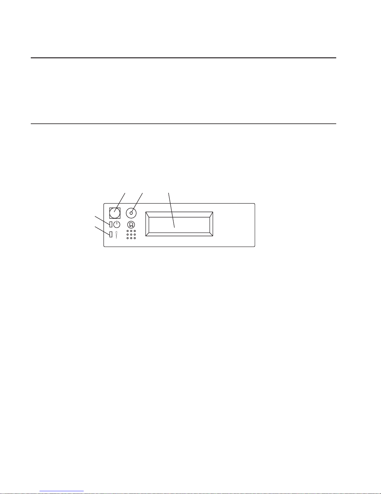
When the power cables are plugged into the electrical outlets, the following occurs:
v The operator panel displays OK, and the green power LED (1) blinks. When this
occurs, your system is in standby mode. The following figure shows the operator
panel in standby mode.
1
2
OK
1 Power-On LED
2 Operator Panel Display
If your system does not stop in standby mode, check all cables for good connection.
If you cannot find a problem, call your support center for assistance.
Chapter 1. Setting Up the System 25
Page 42
Step 21. Your System Unit Is Now Set Up
Arrange your system unit and attached devices so that you can use them comfortably.
If the AIX operating system is not preinstalled on your system and you want to install
the AIX operating system now, refer to the
AIX Installation Guide
, order number
SC23-4112. Return here to continue after your operating system is installed.
Step 22. Start the Operating System
To start the installed AIX operating system, press the power-on switch on the operator
panel.
v The fans in the system unit start spinning.
v The green power LED on the operator panel comes on solid.
v Checkpoint codes appear in the operator panel display.
4
5
1
2
3
1 Power-On Switch
2 Reset Switch
3 Operator Panel Display
4 Attention LED (amber)
5 Power-On LED (green)
v Follow the instructions on your display.
The AIX Documentation library is available at the following web address:
http://www.ibm.com/servers/aix/library/techpubs.html. AIX documentation is also
contained on the
AIX Documentation
CD. The documentation information is made
accessible by loading the documentation CD files onto the hard disk or by mounting the
CD in the CD-ROM drive.
26 Installation Guide
Page 43

Step 23. Accessing Documentation for Your New System
If you are installing this system and another person is the system administrator, deliver
this book to the system administrator when the installation is complete. Ensure that the
system administrator reads the following information and is aware of the options to
access the documentation for the new system.
Hardware Documentation
Hardware documentation, in addition to this installation guide, is available on the Web
or can be ordered in printed hardcopy.
To access the hardware documentation on the Web, go to:
http://www.ibm.com/servers/eserver/pseries/library/hardware_docs
Installation, using, and service documentation is available from this Web site. To order
printed versions of the books that are available in hardcopy, go to:
http://www.ibm.com/shop/publications/order
Operating System Documentation
Documentation for the AIX operating system is available either from the AIX
documentation CD or from the Web.
If you ordered the AIX documentation CD with your operating system, you can access
the information by loading the documentation CD onto a hard disk on your system or by
mounting the AIX documentation CD in the CD-ROM drive. This CD contains the base
set of documentation for the AIX operating system.
To access the complete library for AIX operating system documentation, go to:
http://www.ibm.com/servers/aix/library/techpubs.html
Step 24. Verify the Hardware Operation
If your system did not load the AIX operating system successfully, or you would like to
test your hardware, go to Chapter 2, “Verifying the Hardware Operation” on page 29.
Chapter 1. Setting Up the System 27
Page 44

28 Installation Guide
Page 45

Chapter 2. Verifying the Hardware Operation
The system verification procedure checks the system for correct hardware operation. If
you have a problem with your system in the future, use this procedure to test the
system hardware to help you determine if you have a hardware problem. Run the
system verification procedure as described in the following steps.
Step 1. Considerations Before Running This Procedure
Read the following before using this procedure:
v The AIX operating system must be installed on your system before you attempt to
perform this procedure.
v If this system unit is directly attached to another system unit or attached to a
network, be sure communications with the other systems are stopped.
v This procedure requires use of all of the system resources. No other activity can be
running on the system while you are performing this procedure.
Step 2. Loading the Diagnostics
To run the online diagnostics in service mode from the boot hard disk, do the following:
1. Stop all programs including the AIX operating system (get help if needed).
2. Remove all tapes, diskettes, and CD-ROM discs.
3. Turn off the system unit power.
4. Turn on the system unit power.
5. After the keyboard POST indicator displays on the firmware console and before the
last POST indicator (speaker) displays, press the numeric 6 key on either the
directly attached keyboard or the ASCII terminal to indicate that a service mode
boot should be initiated using the customized service mode boot list.
6. Enter any requested password.
Note: If you are unable to load the diagnostics to the point when the DIAGNOSTIC
OPERATING INSTRUCTIONS display, call your support center for assistance.
Step 3. Running System Verification
When the Diagnostic Operating Instructions display, do the following to run system
verification:
1. Press Enter.
2. To do a general checkout with minimal operator action, select the Diagnostic
Routines option on the Function Selection menu.
To do a more complete checkout including the use of wrap plugs, select the
Advanced Diagnostics option on the Function Selection menu. The advanced
diagnostics are primarily for the service representative; the advanced diagnostics
may instruct you to install wrap plugs to better isolate a problem.
29
Page 46

3. Select the System Verification option on the Diagnostic Mode Selection menu.
4. To run a general checkout of all installed resources, select the All Resource option
on the Diagnostic Selection menu. Follow the instructions on the screen to complete
the checkout procedure.
To check one particular resource, select that resource on the Diagnostic Selection
menu.
The checkout program ends with either of the following results:
v The Testing Complete screen displays a message stating No trouble was found.
v The A Problem Was Detected On (Time Stamp) menu displays, with either a service
request number (SRN) or an error code. Make a note of any codes displayed on the
display or operator panel.
To perform additional system verification, go to “Step 4. Performing Additional System
Verification”. To exit diagnostics, go to “Step 5. Stopping the Diagnostics” on page 31.
Step 4. Performing Additional System Verification
To perform additional system verification, do the following:
1. Press Enter to return to the Diagnostic Selection menu.
2. To check other resources, select the resource. When you have checked all of the
resources you need to check, go to “Step 5. Stopping the Diagnostics” on page 31.
30 Installation Guide
Page 47

Step 5. Stopping the Diagnostics
To stop the diagnostics, do the following:
1. To exit the diagnostics, press the F3 key (from a defined terminal) or press 99 (from
an undefined terminal).
2. If you changed any attributes on your ASCII terminal to run the diagnostics, change
the settings back to normal.
3. This completes the system verification. If you received an error code, record the
code and report it to the service organization.
If the server passed all the diagnostic tests, the verification process is complete and
your server is ready to use.
Chapter 2. Verifying the Hardware Operation 31
Page 48

32 Installation Guide
Page 49

Chapter 3. Installing Options in Your System
This chapter provides instructions to help you add options to your server. Some option
removal instructions are provided, in case you need to remove one option to install
another. If you have several internal options to install, these instructions enable you to
add them all at one time.
Safety Considerations
Observe the following safety precautions anytime you work with this server.
DANGER
An electrical outlet that is not correctly wired could place hazardous voltage
on metal parts of the system or the devices that attach to the system. It is the
responsibility of the customer to ensure that the outlet is correctly wired and
grounded to prevent an electrical shock.
Before installing or removing signal cables, ensure that the power cables for
the system unit and all attached devices are unplugged.
When adding or removing any additional devices to or from the system,
ensure that the power cables for those devices are unplugged before the
signal cables are connected. If possible, disconnect all power cables from the
existing system before you add a device.
Use one hand, when possible, to connect or disconnect signal cables to
prevent a possible shock from touching two surfaces with different electrical
potentials.
During an electrical storm, do not connect cables for display stations, printers,
telephones, or station protectors for communications lines.
CAUTION:
This product is equipped with a three–wire power cable and plug for the user’s
safety. Use this power cable with a properly grounded electrical outlet to avoid
electrical shock.
33
Page 50

Handling Static-Sensitive Devices
Attention: Adapters, planars, diskette drives, and disk drives are sensitive to static
electricity discharge. These devices are wrapped in antistatic bags to prevent this
damage.
Take the following precautions:
v If you have an antistatic wrist strap available, use it while handling the device.
v Do not remove the device from the antistatic bag until you are ready to install the
device in the system unit.
v With the device still in its antistatic bag, touch it to a metal frame of the system unit.
v Grasp cards and boards by the edges. Hold drives by the frame. Avoid touching the
solder joints or pins.
v If you need to lay the device down while it is out of the antistatic bag, lay it on the
antistatic bag. Before picking it up again, touch the antistatic bag and the metal
frame of the system unit at the same time.
v Handle the devices carefully to prevent permanent damage.
Stopping the System Unit
Attention: When shutting down your system to install options, shut down all
applications first and then shut down the operating system. The system power turns off
and the system goes into standby mode when the operating system is shut down.
Before removing power from the system unit, ensure that the shut down process is
complete. Failure to do so can result in the loss of data. Some option installation
procedures do not require the system to be stopped for installation. If necessary, the
option installation procedures in this section will direct you here if stopping the system
is required.
1. Log in to the system as root user.
2. Stop any applications that are running on the system.
3. At a command line, type shutdown to stop the operating system.
4. After you shut down the operating system, set the power switches of any attached
devices to Off.
34 Installation Guide
Page 51

Placing the Model 6C1 in the Service Position
Attention: Care should be taken to ensure that a hazardous condition is not created
due to uneven mechanical loading when placing the server in the service position. If the
rack has a stabilizer it must be firmly attached before placing the server in the service
position.
Before doing any actions inside the Model 6C1, you must put the server in the service
position. To place the server in the service position, release the left and right side
latches and pull the server toward the front until it is fully extended. When the server is
fully extended, safety latches on the slide rails lock into place. This prevents the server
from being accidentally pulled out too far and dropped.
1
After completing actions, return the server to the normal position by pressing in on the
safety latches (1).
Chapter 3. Installing Options in Your System 35
Page 52

Option List
Choose an option from the list below and go to the installation procedures for the option
you are installing.
v Processor Cards
– Installing a Processor Card, see page 42.
– Removing a Processor Card, see page 44.
v System Memory Options
– Installing a Memory Card , see page 46.
– Removing a Memory Card, see page 48.
– Installing Memory DIMMs, see page 50.
– Removing Memory DIMMs, see page 52.
v Adapters
– Installing Adapters, see page 54.
– Removing Adapters, see page 58.
v Disk Drive Options
– Installing Hot-Swap Disk Drives, see page 60.
– Removing Hot-Swap Disk Drives, see page 63.
v Installing a Internal Disk Drive, see page 65.
v Installing a CD-ROM Drive, Tape Drive, DVD-RAM or DVD-ROM, see page 66.
v Configuring or Deconfiguring Disk and Media Drives, see page 68.
v Hot-Swap Power Supplies
– Installing a Hot-Swap Power Supply, see page 69.
– Removing a Hot-Swap Power Supply, see page 71.
v Replacing a Hot-Swap Fan Assembly, see page 73.
v Replacing the Battery, see page 79.
v Connecting the Rack Indicator, see page 81.
36 Installation Guide
Page 53

Removing the Service Access Covers
Service Access Cover (Model 6E1 )
1
CPU
VRM
MEMOR
Y
HDD
PCI B
US
NMI
SMI
SER
VICE PR
OCESSOR
B
US
NON REDUND
ANT
PO
WER SUPPL
Y
1 2 3
A B
1 2 3
FAN
TEMPERA
TURE
2
1 Cover-release latch
2 Service access cover
1. If you are planning to install or remove any part other than a hot-swap hard disk
drive, hot-swap power supply, or hot-swap fan, turn off the server and all attached
devices and disconnect all external cables and power cords.
2. Slide the cover-release lever (1) to the right to release the cover and slide the cover
(2) toward the rear of the server about 25 mm (1 inch). Move the top edge of the
cover out from the server; then, lift the cover off the server. Set the cover aside.
Attention: For proper cooling and airflow, replace the cover before turning on the
server. Operating the server for extended periods of time (over 30 minutes) with the
cover removed might damage server components.
Chapter 3. Installing Options in Your System 37
Page 54

Service Access Cover (Model 6C1)
1
2
3
1 Service access cover
2 Cover-release latch
3 Side latches
1. To install or remove any part other than a hot-swap hard disk drive, hot-swap power
supply, or hot-swap fan, turn off the server and all attached devices and disconnect
all external cables and power cords.
2. If you have not already done so, place the server in the service position as
described in “Placing the Model 6C1 in the Service Position” on page 35.
3. Move the cover-release lever (2) down while sliding the service access cover (1)
toward the rear of the server about 25 mm (1 inch). Lift the cover off the server and
set the cover aside.
Attention: For proper cooling and airflow, replace the cover before turning on the
server. Operating the server for extended periods of time (over 30 minutes) with the
cover removed might damage server components.
38 Installation Guide
Page 55

Removing the Bezel
Refer to the following illustrations while you perform the steps in this procedure.
Bezel (Model 6E1)
CPU
VRM
MEMOR
Y
HDD
PCI B
US
NMI
SMI
SER
VICE PR
OCESSOR
B
US
NON REDUND
ANT
PO
WER SUPPL
Y
1 2 3
A B
1 2 3
F
AN
TEMPERA
TURE
2
3
1
2
3
1 Bezel-release lever
2 Bezel
3 Side with bezel tabs and slots
1. If you have not already done so, remove the service access cover as described in
“Removing the Service Access Covers” on page 37.
2. Press the bezel-release lever (1) and remove the bezel (2).
Chapter 3. Installing Options in Your System 39
Page 56

Bezel (Model 6C1)
1
2
3
1 Bezel-release lever
2 Bezel
3 Side with bezel tabs and slots
1. If you have not already done so. place the server in the service position as
described in “Placing the Model 6C1 in the Service Position” on page 35.
2. If you have not already done so, remove the service access cover as described in
“Removing the Service Access Covers” on page 37.
3. Press the bezel-release lever (1) and remove the bezel (2).
40 Installation Guide
Page 57

Removing and Replacing Processor and Memory Card Cover
Removal
1. If you have not already done so, shut down the system as described in “Stopping
the System Unit” on page 34.
2. If you have not already done so, unplug the system unit power cables from the
electrical outlets.
3. If your server is a Model 6C1 (rack mount), place the server in the service position
as described in “Placing the Model 6C1 in the Service Position” on page 35.
4. If you have not already done so, remove the service access cover as described in
“Removing the Service Access Covers” on page 37.
5. Pull out on the snap button and remove the processor and memory card cover.
Snap
Button
Replacment
Install the processor and memory card cover and push in on the snap button to secure.
Chapter 3. Installing Options in Your System 41
Page 58

Installing a Processor Card
1. If you have not already done so, shut down the system as described in “Stopping
the System Unit” on page 34.
2. If you have not already done so, unplug the system unit power cables from the
electrical outlets.
3. If your server is a Model 6C1 (rack mount), place the server in the service position
as described in “Placing the Model 6C1 in the Service Position” on page 35.
4. If you have not already done so, remove the service access cover as described in
“Removing the Service Access Covers” on page 37.
5. If you have not already done so, remove the processor and memory card cover as
described in “Removing and Replacing Processor and Memory Card Cover” on
page 41.
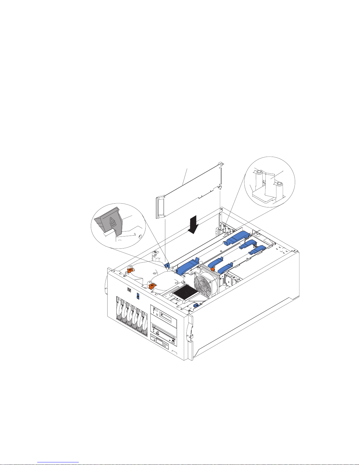
6. Remove the air flow baffle from the system.
7. Remove the plastic boot from the processor card connector.
8. Open the retention latches.
Both
latches should be in an upright position. See the
following illustration.
Attention: To prevent damage to the card and to the card connectors, open or
close both retention latches at the same time.
9. Align the card with the connector.
42 Installation Guide
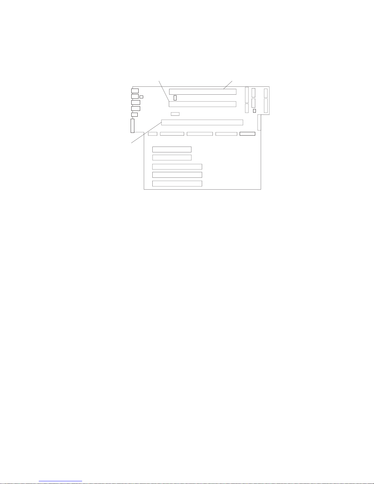
Page 59

Note: If one processor card is installed in the system, the processor must be
installed in the processor card 1 connector.
Processor Card 1
Connector
Memory Card
Connector
Processor Card 2
Connector
10. Close the retention latches securing the card into the connector.
11. If you have other options to install, refer to “Option List” on page 36.
If you do not have other options to install, replace the processor and memory card
cover as described in “Removing and Replacing Processor and Memory Card
Cover” on page 41.
12. Replace the system unit covers as described in “Replacing the Service Access
Covers” on page 77.
Chapter 3. Installing Options in Your System 43
Page 60

Removing a Processor Card
1. If you have not already done so, shut down the system as described in “Stopping
the System Unit” on page 34.
2. If you have not already done so, unplug the system unit power cables from the
electrical outlets.
3. If your server is a Model 6C1 (rack mount), place the server in the service position
as described in “Placing the Model 6C1 in the Service Position” on page 35.
4. If you have not already done so, remove the service access cover as described in
“Removing the Service Access Covers” on page 37.
5. Remove the processor and memory card cover as described in “Removing and
Replacing Processor and Memory Card Cover” on page 41.
6. The processor card is secured in place with retention latches, one on each end of
the card. Open the retention latches.
Attention: To prevent damage to the card and the card connectors, open or close
the retention latches at the same time.
7. Remove the card from the connector. Be sure to store the processor card in a safe
place.
8. If you have other options to install, refer to “Option List” on page 36.
44 Installation Guide
Page 61

If you do not have other options to install, replace the processor and memory card
cover as described in “Removing and Replacing Processor and Memory Card
Cover” on page 41.
9. Replace the system unit covers as described in “Replacing the Service Access
Covers” on page 77.
Chapter 3. Installing Options in Your System 45
Page 62

Installing a Memory Card
1. If you have not already done so, shut down the system as described in “Stopping
the System Unit” on page 34.
2. If you have not already done so, unplug the system unit power cables from the
electrical outlets.
3. If your server is a Model 6C1 (rack mount), place the server in the service position
as described in “Placing the Model 6C1 in the Service Position” on page 35.
4. If you have not already done so, remove the service access cover as described in
“Removing the Service Access Covers” on page 37.
5. If you have not already done so, remove the processor and memory card cover as
described in “Removing and Replacing Processor and Memory Card Cover” on
page 41.
6. Open the retention latches.
Both
latches should be in an upright position. See the
following illustration.
Attention: To prevent damage to the card and to the card connectors, open or
close both retention latches at the same time.
46 Installation Guide
Page 63
7. Align the card with the connector.
Processor Card 1
Connector
Memory Card
Connector
Processor Card 2
Connector
8. Close the retention latches securing the card into the connector.
9. If you have other options to install, refer to “Option List” on page 36.
If you do not have other options to install, replace the processor and memory card
cover as described in “Removing and Replacing Processor and Memory Card
Cover” on page 41.
10. Replace the system unit covers as described in “Replacing the Service Access
Covers” on page 77.
Chapter 3. Installing Options in Your System 47
Page 64

Removing a Memory Card
1. If you have not already done so, shut down the system as described in “Stopping
the System Unit” on page 34.
2. If you have not already done so, unplug the system unit power cables from the
electrical outlets.
3. If your server is a Model 6C1 (rack mount), place the server in the service position
as described in “Placing the Model 6C1 in the Service Position” on page 35.
4. If you have not already done so, remove the service access cover as described in
“Removing the Service Access Covers” on page 37.
5. Remove the processor and memory card cover as described in “Removing and
Replacing Processor and Memory Card Cover” on page 41.
6. The memory card is secured in place with retention latches, one on each end of the
card. Open the retention latches.
Attention: To prevent damage to the card and the card connectors, open or close
the retention latches at the same time.
7. Remove the card from the connector. Be sure to store the memory card in a safe
place.
8. If you have other options to install, refer to “Option List” on page 36.
48 Installation Guide
Page 65

If you do not have other options to install, replace the processor and memory card
cover as described in “Removing and Replacing Processor and Memory Card
Cover” on page 41.
9. Replace the system unit covers as described in “Replacing the Service Access
Covers” on page 77.
Chapter 3. Installing Options in Your System 49
Page 66

Installing Memory DIMMs
1. If you have not already done so, shut down the system as described in “Stopping
the System Unit” on page 34.
2. If you have not already done so, unplug the system unit power cables from the
electrical outlets.
3. If your server is a Model 6C1 (rack mount), place the server in the service position
as described in “Placing the Model 6C1 in the Service Position” on page 35.
4. If you have not already done so, remove the service access cover as described in
“Removing the Service Access Covers” on page 37.
5. If you have not already done so, remove the processor and memory card cover as
described in “Removing and Replacing Processor and Memory Card Cover” on
page 41.
6. If you have not already done so, remove the memory card as described in
“Removing a Memory Card” on page 48.
7. With one hand, touch any metal surface of the chassis to minimize static electrical
charges, and then pick up the memory DIMM.
8. Locate the memory DIMM connector on the memory card.
Slot J1
Slot J3
Slot J4
Slot J2
Slot J5
Slot J6
Slot J9
Slot J10
Slot J11
Slot J12
Slot J13
Slot J14
Slot J15
Slot J16
Slot J7
Slot J8
Note: Memory DIMMs must be installed in pairs and in the correct slot
configuration. (Slots J1 and J2, J3 and J4, J5 and J6, and so on.)
50 Installation Guide
Page 67

9. Insert the memory module firmly into the connector.
Locking Tabs
10. Secure the memory DIMM with the locking tabs located at each end of the
connector.
11. Replace the memory card into the system unit. See “Installing a Memory Card” on
page 46 for more information.
12. If you have other options to install, refer to “Option List” on page 36.
If you do not have other options to install, replace the processor and memory card
cover as described in “Removing and Replacing Processor and Memory Card
Cover” on page 41.
13. Replace the system unit covers as described in “Replacing the Service Access
Covers” on page 77.
Chapter 3. Installing Options in Your System 51
Page 68

Removing Memory DIMMs
1. If you have not already done so, shut down the system as described in “Stopping
the System Unit” on page 34.
2. If you have not already done so, unplug the system unit power cables from the
electrical outlets.
3. If your server is a Model 6C1 (rack mount), place the server in the service position
as described in “Placing the Model 6C1 in the Service Position” on page 35.
4. If you have not already done so, remove the service access cover as described in
“Removing the Service Access Covers” on page 37.
5. If you have not already done so, remove the processor and memory card cover as
described in “Removing and Replacing Processor and Memory Card Cover” on
page 41.
6. If you have not already done so, remove the memory card as described in
“Removing a Memory Card” on page 48
7. Locate the memory DIMM connectors and determine which DIMM you want to
remove.
Slot J1
Slot J3
Slot J4
Slot J2
Slot J5
Slot J6
Slot J9
Slot J10
Slot J11
Slot J12
Slot J13
Slot J14
Slot J15
Slot J16
Slot J7
Slot J8
Note: Memory DIMMs must be removed in pairs and in the correct slot
configuration. (Slots J1 and J2, J3 and J4, J5 and J6, and so on.)
52 Installation Guide
Page 69

8. Remove the memory DIMM by pushing the tabs (1) out on the memory connectors
and then pulling the memory DIMM (2) out of the connector..
Push Locking Tabs
Out to Release Memory
Module
1
2
1
9. Replace the memory card into the system unit. See “Installing a Memory Card” on
page 46 for more information.
10. If you have other options to install, refer to “Option List” on page 36.
If you do not have other options to install, replace the processor and memory card
cover as described in “Removing and Replacing Processor and Memory Card
Cover” on page 41.
11. Replace the system unit covers as described in “Replacing the Service Access
Covers” on page 77.
Chapter 3. Installing Options in Your System 53
Page 70

Installing Adapters
Read “Safety Considerations” on page 33.
1. If you have not already done so, shut down the system as described in “Stopping
the System Unit” on page 34.
2. If you have not already done so, unplug the system unit power cables from the
electrical outlets.
3. If your server is a Model 6C1 (rack mount), place the server in the service position
as described in “Placing the Model 6C1 in the Service Position” on page 35.
4. If you have not already done so, remove the service access cover as described in
“Removing the Service Access Covers” on page 37.
5. Determine which PCI adapter expansion slot you will use for the adapter.
Note: Check the instructions that were provided with the adapter for any
requirements or restrictions. See the
PCI Adapter Placement Reference
,
order number SA38-0538, for more information.
54 Installation Guide
Page 71

1
2
3
1 Adapter retention latch
2 Tab
3 Expansion-slot cover
6. Remove the expansion-slot cover:
a. Rotate the adapter retention latch (1) counterclockwise.
b. Raise the tab (2) on the adapter guide over the tab on the top corner of
adapter.
c. Remove the expansion-slot cover from the server (3). Store it in a safe place
for future use.
Attention: Expansion-slot covers must be installed on all vacant slots. This
maintains the electromagnetic emissions characteristics of the
system and ensures proper cooling of system components.
Chapter 3. Installing Options in Your System 55
Page 72
7. Refer to the documentation that was provided with the adapter for any cabling
instructions. It might be easier for you to route any cables before you install the
adapter.
8. If you are installing a long adapter, press on the touchpoint on the adapter retainer
flap (3) at the end of the slot nearest the front of the server, and rotate the adapter
retainer flap upward.
9. Remove the adapter from the antistatic package.
Attention: Avoid touching the components and gold-edge connectors on the
adapter.
10. Place the adapter, component-side up, on a flat, static-protective surface.
11. Set any jumpers or switches as described by the adapter manufacturer.
2
4
1
3
1 Adapter retention latch
2 Tab
3 Adapter retainer flap
4 Adapter
56 Installation Guide
Page 73

12. Install the adapter.
a. Carefully grasp the adapter (4) by its top edge or upper corners, and align it
with the expansion slot on the system board.
b. Press the adapter
firmly
into the expansion slot.
Attention: When you install an adapter in the server, be sure that it is
completely and correctly seated in the system-board connector.
Incomplete insertion might cause damage to the system board or
the adapter.
c. Lower the tab (2) on the adapter guide over the tab on the top corner of
adapter. Rotate the adapter retention latch (1) clockwise until it snaps into
place.
Attention: Power cannot be restored to the adapter slot if the tab is not
lowered into place.
d. Close the adapter retainer flap (3) if previously opened.
13. Connect any needed cables to the adapter.
Attention: Route cables so that the flow of air from the fans is not blocked.
14. If you have other options to install, refer to “Option List” on page 36.
If you do not have other options to install, replace the covers as described in
“Replacing the Service Access Covers” on page 77.
Chapter 3. Installing Options in Your System 57
Page 74

Removing Adapters
1. If you have not already done so, shut down the system as described in “Stopping
the System Unit” on page 34.
2. If you have not already done so, unplug the system unit power cables from the
electrical outlets.
3. If your server is a Model 6C1 (rack mount), place the server in the service position
as described in “Placing the Model 6C1 in the Service Position” on page 35.
4. If you have not already done so, remove the service access cover as described in
“Removing the Service Access Covers” on page 37.
5. Determine which adapter you are removing.
6. Disconnect any cables attached to the adapter.
4
1
2
3
1 Adapter retention latch
2 Tab
3 Adapter retainer flap
4 Adapter
7. If you are removing a long adapter, press on the touchpoint on the adapter retainer
flap (3) at the end of the slot nearest the front of the server, and rotate the adapter
retainer flap upward.
58 Installation Guide
Page 75

8. Rotate the adapter retention latch (1) counterclockwise.
9. Raise the tab (2) on the adapter guide over the tab on the top corner of the
adapter.
10. Carefully grasp the adapter (4) by its top edge or upper corners, and remove it
from the system board.
11. If you are not installing another adapter in this slot, install an expansion-slot cover
and close the adapter retainer flap (3) if previously opened.
12. If you have other options to install, refer to “Option List” on page 36.
If you do not have other options to install, replace the covers as described in
“Replacing the Service Access Covers” on page 77.
Chapter 3. Installing Options in Your System 59
Page 76

Installing Hot-Swap Disk Drives
Read “Safety Considerations” on page 33.
The hot-swap drive bays support hot-swap drives only.
Note: You do not have to turn off the server to install hot-swap drives in these bays.
However, you must turn off the server when performing any steps that involve
installing or removing cables.
Refer to the following illustrations while you perform the steps in this procedure.
1
1 Filler panel
60 Installation Guide
Page 77

2
3
2 Drive
3 Drive tray handle (in open
position)
1. If the server is a Model 6E1, unlock and open the server door.
Attention: To maintain proper system cooling, do not operate the server for more
than two minutes without either a drive or a filler panel installed for each bay.
2. Remove the filler panel (1) from one of the empty hot-swap bays by inserting your
finger into the depression at the left side of the filler panel and pulling the panel
away from the server.
Attention: Do not remove the drive from the tray assembly.
3. Install the hard disk drive (2) in the hot-swap bay:
a. Ensure the drive tray handle (3) is open (that is, perpendicular to the drive).
b. Align the drive/tray assembly so that it engages the guide rails in the bay.
c. Gently push the drive/tray assembly into the bay until the drive connects to the
backplane.
d. Push the tray handle to the right until it locks.
4. Check the hard disk drive status indicators to verify that the hard disk drives are
operating properly.
5. Repeat the previous steps for all the drives you are installing.
6. Log in as root user.
Chapter 3. Installing Options in Your System 61
Page 78

7. At the command line, type smitty.
8. Select Devices.
9. Select Install/Configure Devices Added After IPL and press Enter. Follow the
instructions on the screen. Successful configuration is indicated by the OK message
displayed next to the Command field at the top of the screen.
10. Press F10 to exit smitty.
11. If you have other options to install, refer to “Option List” on page 36.
If you do not have other options to install, close and lock the server door
62 Installation Guide
Page 79

Removing Hot-Swap Disk Drives
You do not have to turn off the server to remove a drive from the hot-swap bays.
Attention:
1. Before you remove a hot-swap hard disk drive that is not defective, back up all
important data.
2. To avoid damage to a hard disk drive,
do not
remove the drive from the hot-swap
bay until it has had time to spin down (approximately 30 seconds). Handle the drive
carefully.
3. Before you hot-swap a drive, make sure it is defective. If you partially or completely
remove a good drive instead of a defective one, the server might lose valuable data.
Refer to the following illustration while you perform the steps in this procedure.
2
3
2 Drive
3 Drive tray handle (in open
position)
Chapter 3. Installing Options in Your System
63
Page 80

1. If the server is a Model 6E1, unlock and open the server door.
Attention: To maintain proper system cooling, do not operate the server for more
than two minutes without either a drive or a filler panel installed for each bay.
2. Log in as root user.
3. At the command line, type smitty.
4. Select System Storage Management (Physical and Logical Storage).
5. Select Removable Disk Management.
6. Select Remove a Disk.
7. Select the desired disk from the list on the screen and press Enter.
8. Follow the instructions on the screen to remove the drive.
9. When you are asked ″Are you sure?″ answer “Yes” and press Enter. The power
LED on the drive that you selected turns off.
10. Remove the defective hard disk drive (2) by placing the handle (3) on the drive to
the open position (perpendicular to the drive) and pulling the hot-swap tray from
the bay.
11. Repeat the previous steps for all the drives you are removing.
12. Press F10 to exit smitty.
13. If you have other options to install, refer to “Option List” on page 36.
If you do not have other options to install, close and lock the server door.
64 Installation Guide
Page 81

Installing an Internal Disk Drive
1. If you have not already done so, shut down the system as described in “Stopping
the System Unit” on page 34.
2. If you have not already done so, unplug the system unit power cables from the
electrical outlets.
3. If your server is a Model 6C1 (rack mount), place the server in the service position
as described in “Placing the Model 6C1 in the Service Position” on page 35.
4. Remove the bezel as described in “Removing the Bezel” on page 39.
5. Remove the operator panel by grasping the release levers (1) and pull the
operator panel tray from the system unit.
6. With one hand, touch any metal surface of the chassis to minimize static electrical
charges, and then pick up the disk drive.
7. Insert the disk drive into the operator panel tray.
1
8. Align the screw holes on the disk drive with the screw holes on the operator panel
tray.
9. Install the four retaining screws.
10. Install the operator panel tray back into the system unit.
11. Connect all disk drive cables.
12. If you have other options to install, refer to “Option List” on page 36.
If you do not have other options to install; replace the bezel as described in
“Replacing the Bezel” on page 75.
Chapter 3. Installing Options in Your System 65
Page 82

Installing a CD-ROM, Tape Drive, DVD-RAM, or DVD-ROM
Read “Safety Considerations” on page 33.
1. If you have not already done so, shut down the system as described in “Stopping
the System Unit” on page 34.
2. If you have not already done so, unplug the system unit power cables from the
electrical outlets.
3. If your server is a Model 6C1 (rack mount), place the server in the service position
as described in “Placing the Model 6C1 in the Service Position” on page 35.
4. Remove the bezel as described in “Removing the Bezel” on page 39.
5. Remove the filler panel from the bay opening by pulling the filler panel away from
the server. You do not need the filler panel when you have a drive installed in the
bay.
6. Touch the static-protective bag containing the drive to any unpainted metal surface
on the server; then, remove the drive from the bag and place it on an antistatic
surface.
7. Set any jumpers or switches on the drive according to the documentation that was
provided with the drive.
8. Install rails on the drive.
a. Pull the blue slide rails off the back of the filler panel.
66 Installation Guide
Page 83

b. Clip the rails onto the sides of the drive.
9. Place the drive so that the slide rails engage in the bay guide rails. Push the drive
into the bay until it clicks into place.
10. Connect one of the connectors on the SCSI cable for the non-hot-swap drive bays
to the back of the drive.
11. Connect a power cable to the back of the drive. Power cables for non-hot-swap
drives are preinstalled in the server. The connectors are keyed and can be inserted
only one way.
12. If you have other options to install, refer to “Option List” on page 36.
If you do not have other options to install; replace the bezel as described in
“Replacing the Bezel” on page 75.
Chapter 3. Installing Options in Your System 67
Page 84

Configuring or Deconfiguring Disk Drives
To configure or deconfigure a drive, use the following procedures:
Configuring Drives
1. Log in as root user.
2. At the command line, type smitty.
3. Select System Storage Management (Physical and Logical Storage) and press
Enter.
4. Select Logical Volume Manager and press Enter.
5. Select Volume Groups and press Enter.
6. Select Set Characteristics of a Volume Group and press Enter.
7. Select Add a Physical Volume to a Volume Group.
8. Fill in the fields for the drive you are adding to the system. Press F4 for a list of
selections.
See the
AIX System Management Guide: Operating System and Devices
to finish
the drive configuration. This publication is available at the following Web address:
http://www-1.ibm.com/servers/aix/library/. Select Technical Publications. This
publication is also contained on the
AIX Documentation
CD. The documentation is
made accessible by loading the documentation CD files onto the hard disk or by
mounting the CD in the CD-ROM drive.
9. Press F10 to exit smitty.
Deconfiguring Drives
1. Log in as root user.
2. At the command line, type smitty.
3. Select System Storage Manager (Physical and Logical Storage) and press
Enter.
4. Select Logical Volume Manager and press Enter.
5. Select Volume Groups and press Enter.
6. Select Set Characteristics of a Volume Group. and press Enter.
7. Select Remove a Physical Volume from a Volume Group.
8. Press F4 to list the available volume groups, then select the volume group name
and press Enter.
9. Press F4 to select a physical volume, and follow the instructions on the screen to
select the physical volume. Then press Enter.
10. Return to the procedure that directed you here.
68 Installation Guide
Page 85

Installing a Hot-Swap Power Supply
Read “Safety Considerations” on page 33.
The server comes with two power supplies. You can add a third power supply. With a
third power supply installed the system continues to function if a single power supply
fails. Refer to the following illustration while performing the steps in this procedure.
1
4
5
6
7
2
3
1 Power supply 2 Filler panel
3 Cable-restraint bracket 4 Power cord connector
5 Handle on power supply (in open
position)
6 AC power light
7 DC power light
Chapter 3. Installing Options in Your System
69
Page 86

Note: You do not need to turn off the power to the server to install hot-swap power
supplies if your system has a redundant power supply.
1. Remove the filler panel (2) from the empty power supply bay by inserting your finger
into the depression on the filler panel and pulling it away from the server. Save the
filler panel in case you remove the power supply at a later time.
Note: During normal operation, each power-supply bay must have either a power
supply or filler panel installed for proper cooling.
2. Install the power supply (1) in the bay:
a. Place the handle (5) on the power supply in the open position (that is,
perpendicular to the power supply) and slide the power supply into the chassis.
b. Gently close the handle to seat the power supply in the bay.
3. Plug the power cord for the added power supply into the power cord connector (4).
4. Route the power cord through the cable-restraint bracket (3).
5. Plug the power cord into a properly grounded electrical outlet.
6. Verify that the DC Power light (7) and AC Power light (6) on the power supply are
lit, indicating that the power supply is operating correctly.
7. If you have other options to install, refer to “Option List” on page 36.
70 Installation Guide
Page 87

Removing a Hot-Swap Power Supply
Read “Safety Considerations” on page 33.
Refer to the following illustration while performing the steps in this procedure.
1
4
5
6
7
2
3
1 Power supply 2 Filler panel
3 Cable-restraint bracket 4 Power cord connector
5 Handle on power supply (in open
position)
6 AC power light
7 DC power light
Chapter 3. Installing Options in Your System
71
Page 88

Note: You do not need to turn off the power to the server to install hot-swap power
supplies if your system has a redundant (third) power supply installed.
1. If your system does not have a redundant (third) power supply installed, shut down
the system as described in “Stopping the System Unit” on page 34 and turn off the
power to the server and peripheral devices. Otherwise, go to the next step.
2. To remove the power supply (1):
a. Unplug the power cord connector from the power supply.
Attention: Be careful when you remove the hot-swap power supply; the power
supply might be too hot to handle comfortably.
b. Remove the defective power supply by placing the handle (5) on the power
supply in the open position (perpendicular to the power supply) and pulling the
power supply from the bay.
3. If you are not replacing the power supply:
a. Install a power-supply filler panel (2).
Note: During normal operation, each power-supply bay must have either a
power supply or filler panel installed for proper cooling.
b. Open the cable-restraint bracket (3) and remove the power cord from the
cable-restraint bracket. Close the cable-restraint bracket.
c. Unplug the power cord from the electrical outlet.
If you are replacing the power supply:
a. Place the handle (5) on the power supply in the open position, and slide the
power supply into the chassis.
b. Gently close the handle on the power supply to seat the power supply in the
bay.
c. Plug the power cord for the power supply into the power cord connector (4).
d. Verify that the AC Power light (6) and DC Power light (7) are lit, indicating that
the power supply is operating correctly.
e. If you have other options to install, refer to “Option List” on page 36.
72 Installation Guide
Page 89

Replacing a Hot-Swap Fan Assembly
Read “Safety Considerations” on page 33.
The server comes with four hot-swap fan assemblies.
Attention: Replace a fan that has failed within 48 hours to help ensure proper cooling.
Note: You do not need to turn off the power to the server to replace a hot-swap fan
assembly.
The following illustration shows the replacement of a hot-swap fan assembly. Refer to
this illustration while performing the steps in this procedure.
1
2
3
4
5
6
7
8
9
10
11
12
1 Hot-swap fan assembly 1 2 Fan assembly 1 LED
3 Fan 1 release button 4 Hot-swap fan assembly 2
5 Fan assembly 2 LED 6 Fan 2 release button
7 Fan assembly 3 LED 8 Hot-swap fan assembly 3
9 Fan 3 release latch 10 Fan assembly 4 LED
11 Hot-swap fan assembly 4 12 Fan 4 release latch
Chapter 3. Installing Options in Your System
73
Page 90

1. If your server is a Model 6C1 (rack mount), place the server in the service position
as described in “Placing the Model 6C1 in the Service Position” on page 35.
2. For fan assemblies 2, 3, and 4 you must remove the service access cover. See
“Removing the Service Access Covers” on page 37.
Attention: To ensure proper system cooling, do not remove the service access
cover for more than 30 minutes during this procedure.
3. Determine which fan assembly (fan assembly 1 (1), fan assembly 2 (4), fan
assembly 3 (8) or fan assembly 4 (11)) to replace by checking the fan LEDs on the
indicator panel (see Chapter 4, “Attention LED and Lightpath LEDs” on page 83)
and the LEDs located on the fan assemblies.
4. If you are removing fan assembly 2, you must remove the processor and memory
card cover. See “Removing and Replacing Processor and Memory Card Cover” on
page 41.
5. If you are removing fan assembly 1 or fan assembly 2, pull out the snap button and
remove the fan.
If you are removing fan assembly 3 or fan assembly 4, press the orange release
latch (9), or (12) for the fan and pull the fan away from the server. Slide the
replacement fan assembly into the server until it clicks into place.
6. Verify that the FAN LED on the diagnostic panel is not lit. If the FAN LED is lit,
reseat the fan.
7. If removed earlier, replace the processor and memory card cover. See “Removing
and Replacing Processor and Memory Card Cover” on page 41.
8. Replace the service access cover. See “Replacing the Service Access Covers” on
page 77.
74 Installation Guide
Page 91

Replacing the Bezel
Bezel (Model 6E1)
CPU
VRM
MEMOR
Y
HDD
PCI B
US
NMI
SMI
SER
VICE PR
OCESSOR
B
US
NON REDUND
ANT
PO
WER SUPPL
Y
1 2 3
A B
1 2 3
F
AN
TEMPERA
TURE
1
2
1 Trim bezel
2 Slots (hidden by bezel)
Note: When replacing the bezel, check the serial number on the bezel with the serial
number on the front of the system to ensure that you are installing the correct
bezel on the correct system.
1. Place the tabs at the bottom edge of the trim bezel (1) in the slots (2) at the bottom
front of the server.
2. Press the top of the bezel toward the server until the bezel clicks into place.
Chapter 3. Installing Options in Your System 75
Page 92

Bezel (Model 6C1)
3
2
1
1 Bezel-release lever
2 Trim bezel
3 Slots (hidden by bezel)
Note: When replacing the bezel, check the serial number on the bezel with the serial
number on the front of the system to ensure that you are installing the correct
bezel on the correct system.
1. Place the tabs on the left side of the trim bezel in the slots (3) at the left front of the
server.
2. Press the right end of the bezel toward the server until the bezel clicks into place.
76 Installation Guide
Page 93

Replacing the Service Access Covers
Service Access Cover (Model 6E1)
Refer to the following illustration to install the service access cover.
CPU
VRM
MEMOR
Y
HDD
PCI B
US
NMI
SMI
SER
VICE PR
OCESSOR
B
US
NON REDUND
ANT
PO
WER SUPPL
Y
1 2 3
A B
1 2 3
FAN
TEMPERA
TURE
1
2
1 Slots
2 Service access cover
1. Align the left-side cover (2) with the left side of the server, about 25 mm (1 inch)
from the front of the server; place the bottom of the left-side cover on the bottom rail
of the left-side side of the chassis.
2. Insert the tabs at the top of the cover into the slots (1) at the top of the server side.
3. Hold the cover against the server, and slide the cover toward the front of the server
until the cover clicks into place.
Chapter 3. Installing Options in Your System 77
Page 94

Service Access Cover (Model 6C1)
Refer to the following illustration to install the service access cover.
1
2
3
1 Service access cover
2 Side latches
3 Flanges
1. Align the service access cover (1) with the top of the server, about 25 mm (1 inch)
from the front of the server. The flanges on the left and right sides of the cover
should be on the outside of the server chassis.
2. Hold the cover against the server, and slide the cover toward the front of the server
until the cover clicks into place.
78 Installation Guide
Page 95

Replacing the Battery
CAUTION:
A lithium battery can cause fire, explosion, or a severe burn. Do not recharge,
disassemble, heat above 100 degrees C (212 degrees F), solder directly to the
cell, incinerate, or expose cell contents to water. Keep away from children.
Replace only with the part number specified for your system. Use of another
battery may represent a risk of fire or explosion.
The battery connector is polarized; do not attempt to reverse the polarity.
Dispose of the battery according to local regulations.
1. If you have not already done so, shut down the system as described in “Stopping
the System Unit” on page 34.
2. If you have not already done so, unplug the system unit power cables from the
electrical outlets.
3. If your server is a Model 6C1 (rack mount), place the server in the service position
as described in “Placing the Model 6C1 in the Service Position” on page 35.
4. If you have not already done so, remove the service access cover as described in
“Removing the Service Access Covers” on page 37.
5. If you have not already done so, remove the processor and memory card cover as
described in “Removing and Replacing Processor and Memory Card Cover” on
page 41.
Chapter 3. Installing Options in Your System 79
Page 96

6. Locate the battery on the system board.
Rear Battery Clip
Battery P/N
15F8409
Plastic Battery Mount
Battery
Memory Card
Connector
Processor Card
Connectors
7. If needed, remove any processor cards or memory card to gain access to the
battery.
8. Pry the battery out of its mount using your fingernail or a small blunt object. After
the top of the battery has cleared the plastic mount, pull it up and out of the
system board.
9. Ensure that the battery polarity is correct.
10. Using your thumb, gently press the battery into the battery mount. Use your index
finger to support the back of the battery mount during this operation.
11. Replace any removed processor or memory cards.
12. Replace the processor and memory card cover as described in “Removing and
Replacing Processor and Memory Card Cover” on page 41.
13. Replace the system unit covers as described in “Replacing the Service Access
Covers” on page 77.
14. Reset the time and date.
15. If running AIX, the bootlist command may have to be run from AIX while logged in
as root user. This restores the custom boot list and allow the option of Select
Software under multiboot to start the operating system. The IP (Internet Protocol)
parameters might have to be rebuilt also.
80 Installation Guide
Page 97

Connecting the Rack Indicator
The rack indicator feature signals when a drawer installed in a rack has a failure.
Connect the rack indicator cable.
Chapter 3. Installing Options in Your System 81
Page 98

82 Installation Guide
Page 99

Chapter 4. Attention LED and Lightpath LEDs
The Attention and Lightpath LEDs provide for an obvious and intuitive means to identify
failing components in your server.
Operator Panel Display
When a failing component is detected in your server, the Attention LED is turned on. To
further help you identify the failing component, go to the indicator panel (see “Indicator
Panel” on page 84) inside the server and check which LEDs are on. If either of the
following conditions exists:
v No LEDs lit on the indicator panel
v PCI LED is the only LED lit on the indicator panel
Go to Step 3 in “Problem Determination Using the Standalone or Online Diagnostics” on
page 87. Otherwise, continue with this procedure.
4
5
1
2
3
1 Power-On Switch
2 Reset Switch
3 Display
4 Attention LED
5 Power-On LED
83
Page 100

Indicator Panel
You can access the indicator panel without any tools. The panel provides enough
information to identify the area that needs attention. The panel contains a group of
amber LEDs that indicate which functional area of the system is experiencing the fault
(such as power, CPUs, memory, fans). If one of these LEDs is on, the user or service
representative is directed to the physical area of the server where an additional LED will
be on, indicating the component that is responsible for the current fault.
Indicator
Panel
84 Installation Guide
 Loading...