

Page 1

Expan dabl e Storage Plus
210 4 Model s DU3 and TU 3
Hardware Technical Information
SA33-3309-00
Page 2

Page 3

Expan dabl e Storage Plus
210 4 Model s DU3 and TU 3
Hardware Technical Information
SA33-3309-00
Page 4

First Edition (October 2000)
The following paragraph does not apply to any country where such provisions are inconsistent with local law:
THIS PUBLICATION IS PRINTED “AS IS” WITHOUT WARRANTY OF ANY KIND, EITHER EXPRESS OR IMPLIED,
INCLUDING, BUT NOT LIMITED TO, THE IMPLIED WARRANTIES OF MERCHANTABILITY OR FITNESS FOR A
PARTICULAR PURPOSE. Some states do not allow disclaimer of express or implied warranties in certain transactions;
therefore, this statement may not apply to you.
This publication could contain technical inaccuracies or typographical errors. Changes are periodically made to the
information herein; these changes will be incorporated in new editions of the publication.
It is possible that this publication may contain reference to, or information about, products (machines and programs),
programming, or services that are not announced in your country. Such references or information must not be
construed to mean that such products, programming, or services will be offered in your country. Any reference to a
licensed program in this publication is not intended to state or imply that you can use only the licensed program
indicated. You can use any functionally equivalent program instead.
© Copyright International Business Machines Corporation, 2000. All rights reserved.
Note to U.S. Government Users – Documentation related to restricted rights – Use, duplication, or disclosure is subject
to restrictions set forth in the GSA ADP Schedule Contract.
Page 5

Contents
About This Book .......................v
Related Publications ......................v
Trademarks ........................v
Chapter 1. Introduction .....................1
2104 Model DU3 .......................2
2104 Model TU3........................4
SCSI Disk Drive Modules.....................6
SCSI Interface Cards ......................7
Fan-and-Power-Supply Assemblies .................8
Switch Card .........................9
SCSI Bus Bridge Card .....................10
SCSI Bus Configurations ...................10
Chapter 2. Product Characteristics ................13
Dimensions .........................13
Weight ..........................13
Service Clearances ......................13
Environment ........................14
Temperature and Humidity ...................14
Altitude .........................14
Heat Output, Airflow, and Cooling .................15
Electrical Power .......................16
Input-voltage Requirements ..................16
Power Input ........................16
Power Factor .......................17
Output Protection ......................17
Early Power-Off Warning (EPOW) ................17
Power Control ........................18
Power Sequencing .....................18
Auto Restart .......................18
Safety Approvals .......................19
Electromagnetic Compatibility ...................20
Federal Communications Commission (FCC) Statement .........20
Japanese Voluntary Control Council for Interference (VCCI) Statement ....20
Korean Government Ministry of Communication (MOC) Statement......20
New Zealand Compliance Statement ...............20
International Electrotechnical Commission (IEC) Statement ........20
Avis de conformitéàla réglementation d’Industrie Canada ........20
Industry Canada Compliance Statement ..............21
United Kingdom Telecommunications Requirements ..........21
European Union (EU) Statement .................21
Radio Protection for Germany ..................21
Taiwan Class A Compliance Statement ...............22
Chapter 3. Physical Connections .................23
SCSI Adapters and Cables ....................25
iii
Page 6

Mainline-Power Connectors ...................26
iv 2104 Models DU3 and TU3 Hardware Technical Information
Page 7

About This Book
This book is intended for system designers, programmers, engineers, and other
professionals who need to understand the 2104 Models DU3 and TU3.
Chapter 1 contains an introduction and general information about the components of
the 2104 Models DU3 and TU3.
Chapter 2 contains a summary of the physical characteristics of the 2104 Models DU3
and TU3.
Chapter 3 contains information about the external connectors of the 2104 Models DU3
and TU3.
Related Publications
ANSI1specification SCSI/2 X3T9.2/86-109 revision 10H
ANSI specification X3.131-199X
Site and Hardware Planning Information, SA38-0508
Adapters, Devices, and Cables Information for Multiple Bus Systems, SA38-0516
Expandable Storage Plus : 2104 Models DU3 and TU3 Operator’s Guide,
SA33-3310
Expandable Storage Plus : 2104 Model DU3 Installation Guide, GA33-3311
Expandable Storage Plus : 2104 Model TU3 Installation Guide, GA33-3312
Expandable Storage Plus : 2104 Models DU3 and TU3 Service Guide, GY33-0198
Trademarks
The following items are trademarks of International Business Machines Corporation in
the United States, or other countries, or both:
v AIX
v IBM
v RS/6000
v
TM
1. American National Standards Institute.
v
Page 8

vi 2104 Models DU3 and TU3 Hardware Technical Information
Page 9
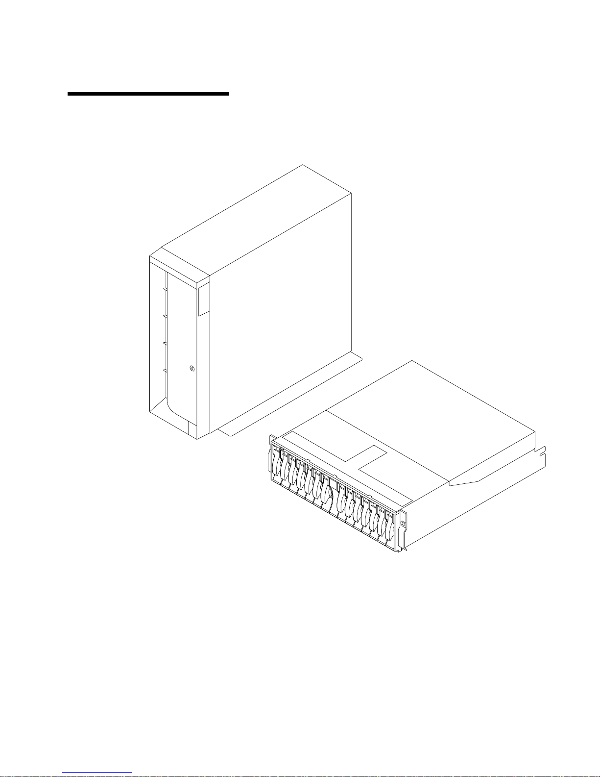
Chapter 1. Introduction
This section describes the 2104 Models DU3 and TU3 and their components.
Figure 1. 2104 Model TU3 (on the Left) and 2104 Model DU3 (on the Right)
1
Page 10
2104 Model DU3
The 2104 Model DU3 is a rack-mounted SCSI disk enclosure that can be attached to
any RS/6000 or IBM
™
server
TM
™
pSeries computer that provides support for any of
the Small Computer System Interface (SCSI) adapters listed in “SCSI Adapters and
Cables” on page 25.
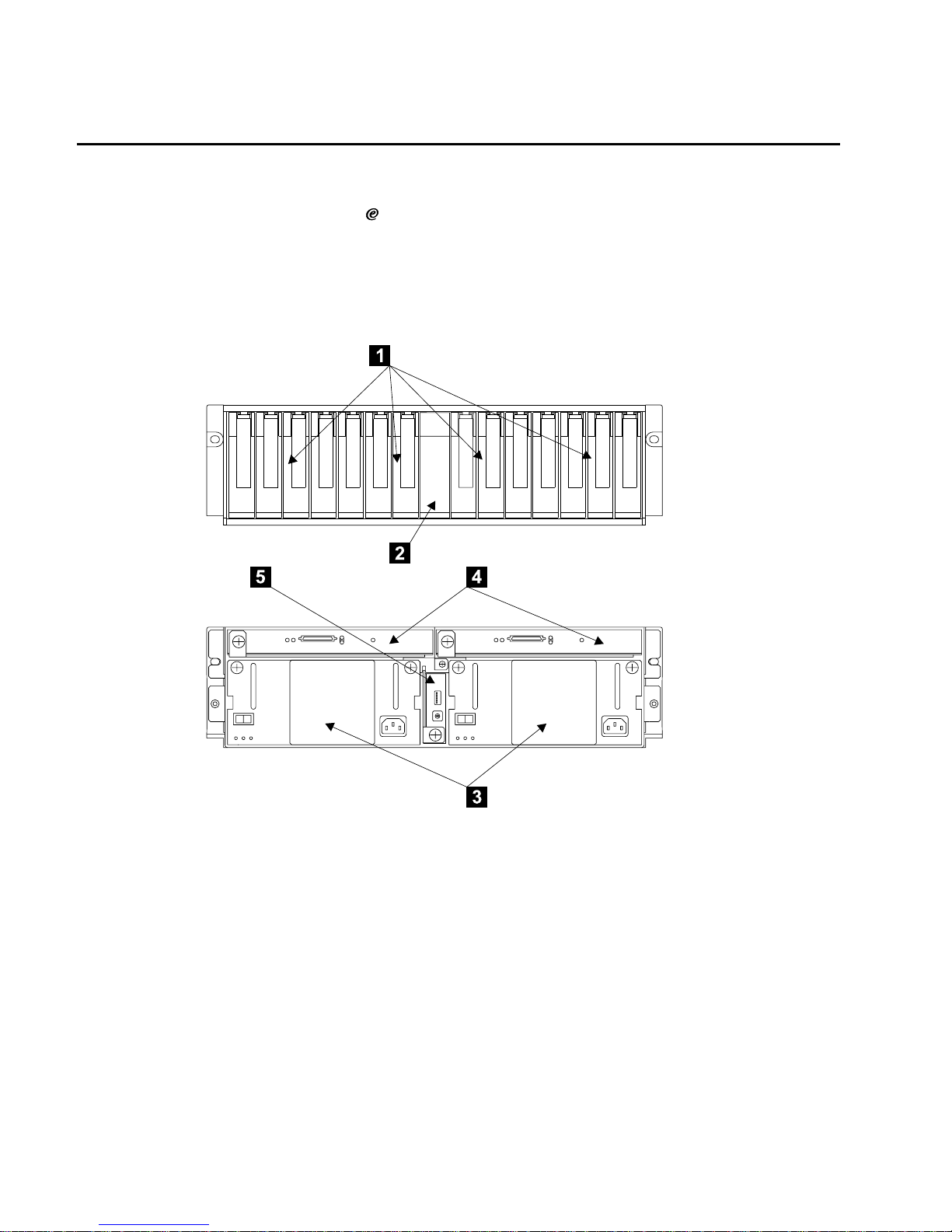
A fully configured 2104 Model DU3 looks like this:
At the front of a 2104 Model DU3 there are 14 device slots 1. In a fully configured
2104 Model DU3, each slot contains a SCSI disk drive module. If a 2104 Model DU3 is
not fully configured, each slot that does not contain a SCSI disk drive module must
contain a dummy module.
Note: At least one SCSI disk drive module must be present in each 2104 Model DU3.
Each disk drive module connects to a backplane that is mounted vertically about
halfway between the front and back of the 2104 Model DU3.
The 14 device slots are divided into two groups of seven slots. Between the two groups
of slots there is a SCSI bus bridge card 2. The SCSI bus bridge card assigns the disk
drive modules to a SCSI bus, in accordance with the setting of the SCSI bus split
switch on the switch card.
Figure 2. 2104 Model DU3 from the Front (Top) and Back (Bottom)
2 2104 Models DU3 and TU3 Hardware Technical Information
Page 11

On the back of the backplane are connectors for two fan-and-power-supply
assemblies3, two SCSI interface cards4, and a switch card5.
The 2104 Model DU3 has either two fan-and-power-supply assemblies or one
fan-and-power-supply assembly and one fan assembly. Either option provides all the
necessary power and cooling for the 2104 Model DU3.
The SCSI interface cards are used to connect host machines to the 2104 Model DU3.
These cards contain logic that provides information about what is happening in the
2104 Model DU3 and the status of components within it.
The switch card contains switches that control which SCSI bus mode is selected, how
the 2104 Model DU3 is supplied with power, and what enclosure services are enabled.
It also contains a rotary switch that is used to set the ID of the 2104 Model DU3.
Chapter 1. Introduction 3
Page 12

2104 Model TU3
The 2104 Model TU3 is a deskside SCSI disk enclosure that can be attached to any
RS/6000 or IBM
server
pSeries computer that provides support for any of the Small
Computer System Interface (SCSI) adapters listed in “SCSI Adapters and Cables” on
page 25.
A fully configured 2104 Model TU3 looks like this:
At the front of a 2104 Model TU3 are 14 device slots 1. In a fully configured 2104
Model TU3, each slot contains a SCSI disk drive module. If a 2104 Model TU3 is not
fully configured, each slot that does not contain a SCSI disk drive module must contain
a dummy module.
Note: At least one SCSI disk drive module must be present in each 2104 Model TU3.
Each disk drive module connects to a backplane that is mounted vertically about
halfway between the front and back of the 2104 Model TU3.
The 14 device slots are split into two groups of seven slots. Between the two groups of
slots, there is a SCSI bus bridge card 2. The SCSI bus bridge card assigns the disk
drive modules to a SCSI bus, in accordance with the setting of the SCSI bus split
switch on the switch card.
On the back of the backplane are connectors for two fan-and-power-supply
assemblies3, two SCSI interface cards4, and a switch card5.
Figure 3. 2104 Model TU3 from the Front (Left) and Back (Right)
4 2104 Models DU3 and TU3 Hardware Technical Information
Page 13

The 2104 Model TU3 can have either two fan-and-power-supply assemblies or one
fan-and-power-supply assembly and one fan assembly. Either option provides all the
necessary power and cooling for the 2104 Model TU3.
The SCSI interface cards are used to connect host machines to the 2104 Model TU3.
These cards contain logic that provides information about what is happening in the
2104 Model TU3, and controls the operation of the subsystem.
The switch card contains switches that control which SCSI bus mode is selected, how
the 2104 Model TU3 is supplied with power, and what enclosure services are enabled.
It also contains a rotary switch that is used to set the ID of the 2104 Model TU3.
Chapter 1. Introduction 5
Page 14

SCSI Disk Drive Modules
Each 2104 Model DU3 or TU3 includes from one to fourteen SCSI disk drive modules.
In your initial order, you can select the capacity of these disk drive modules. Each disk
slot contains either a disk drive module or a dummy module. You can replace any
dummy module with a disk drive module, or any disk drive module with a dummy
module, but there must always be at least one disk drive module in each 2104 disk
enclosure, and every disk slot must contain either a disk drive module or a dummy
module. You can install the additional disk drive modules yourself.
The following IBM disks are allowed:
Nominal capacity Nominal Speed in RPM Feature Number
9.1 GB 10000 6109
18.2 GB 10000 6118
36.4 GB 10000 6136
Please obtain the latest product information from the following IBM Web address:
www.ibm.com/storage
6 2104 Models DU3 and TU3 Hardware Technical Information
Page 15

SCSI Interface Cards
Attached to the back of the backplane in a fully configured 2104 Model DU3 or 2104
Model TU3 are two SCSI interface cards. Both cards can be used to connect host
machines to the 2104 disk enclosure. A SCSI interface card provides the following
functions:
v Supports SCSI Enclosure Services at the SCSI node at address 15 on the external
SCSI bus
v Reads the Vital Product Data (VPD) for the backplane, the fan-and-power-supply
assembly, the fan assembly, the switch card, the SCSI interface card, and the SCSI
bus bridge card
v Inputs the fan-and-power-supply assembly fault lines
v Controls the fan-and-power-supply assembly fault LEDs and the fan assembly fault
LED
v Controls the fault LED at the front of the 2104 Model DU3 or 2104 Model TU3
v Monitors the EPOW (Early Power-Off Warning) signal from the power supplies, and
passes this information to the disks when needed
v Supports hot plugging of disk drive modules
v Detects and indicates faults within itself
v Supports LVD (low-voltage differential) Ultra3 SCSI (160MB per second data rate)
Note: Single-ended (SE) SCSI is not supported.
The other SCSI interface card detects and indicates only faults within itself. However, if
the first SCSI interface card fails, the second SCSI interface card provides all the
functions previously provided by the other SCSI interface card.
If the 2104 contains only one SCSI interface card, the SCSI interface card provides all
the functions listed above.
Chapter 1. Introduction 7
Page 16

Fan-and-Power-Supply Assemblies
Attached to the back of the backplane in a fully configured 2104 Model DU3 or 2104
Model TU3 are two fan-and-power-supply assemblies.
Each fan-and-power-supply assembly provides enough power for the 2104, so it is
possible for there to be just one fan-and-power-supply assembly in a 2104. The second
fan-and-power-supply assembly is replaced by a fan assembly. The
fan-and-power-supply assembly provides the power for the fan assembly via the 2104
backplane.
8 2104 Models DU3 and TU3 Hardware Technical Information
Page 17

Switch Card
Attached to the back of the backplane in a fully configured 2104 Model DU3 or 2104
Model TU3, the switch card contains switches that control some of the functions of the
2104.
Switches that are accessible from the back of the 2104 are provided to indicate:
v Whether power to the 2104 is turned on or off automatically when the host computer
is switched on or off
v Whether the disk drive modules are started automatically when power to the 2104 is
turned on
v Whether the disk drive modules are all started simultaneously or sequentially
v Whether enclosure services can operate
v Which enclosure services, ANSI SCSI-3 Enclosure Services (SES) or Conner/Intel
SCSI-accessed Fault-tolerant Enclosures (SAF-TE), can operate
v The ID of the 2104
Switches that are accessible only when the switch card has been removed from the
2104 are provided to indicate:
v That the order of the SCSI addresses is reversed
v Whether the setting of the LEDs is for a rack-mounted unit or for a deskside unit
v Whether the 2104 is configured as single SCSI bus mode or dual SCSI bus mode
Chapter 1. Introduction 9
Page 18

SCSI Bus Bridge Card
Located centrally in the front of a 2104 Model DU3 or 2104 Model TU3, the SCSI bus
bridge card controls the SCSI bus configuration of the 2104. It assigns the disk drive
modules to a SCSI bus, in accordance with the setting of the SCSI bus split switch on
the switch card.
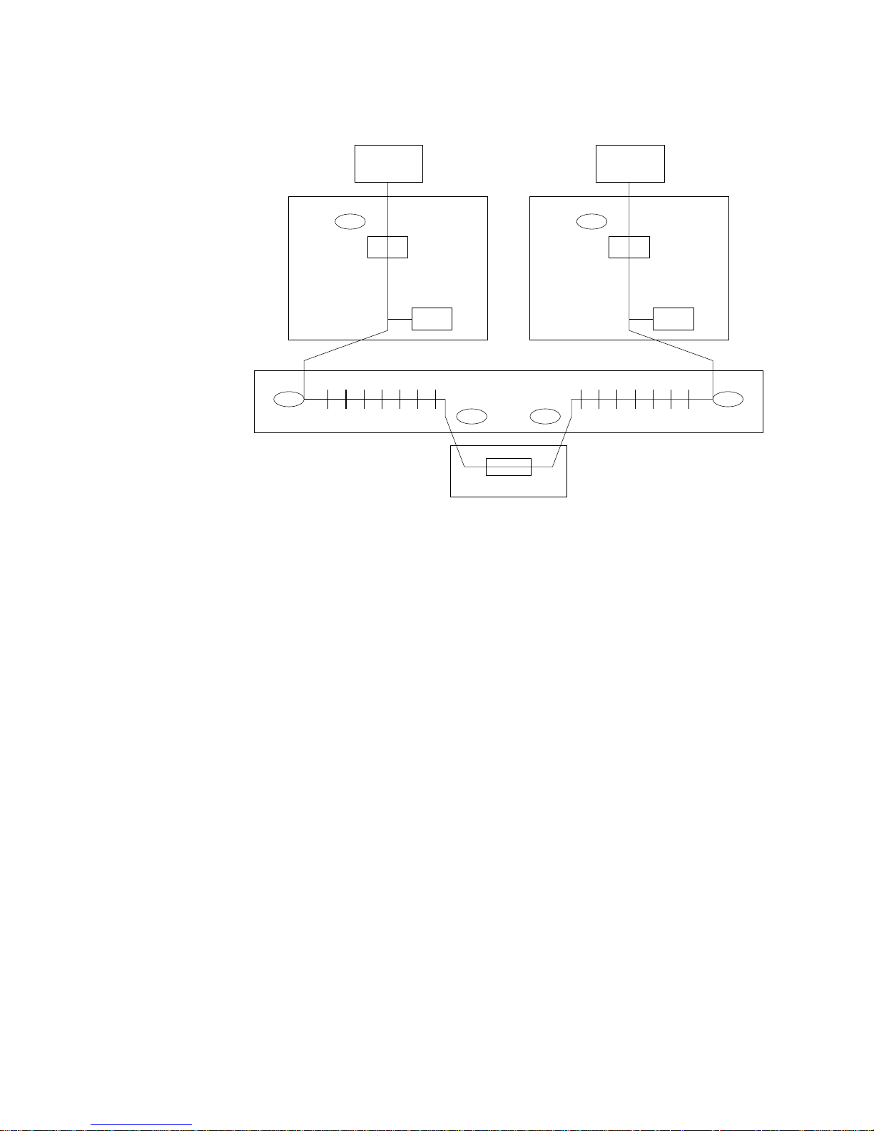
SCSI Bus Configurations
There are three valid configurations :
v Single bus, one initiator (SCSI ID 7), 14 disk drive modules (SCSI IDs 0 through 6,
and 8 through 14)
v Single bus, two initiators (SCSI IDs 5 and 6), 12 disk drive modules (SCSI IDs 0
through 4, and 8 through 14)
Note: In this configuration, slots 6 and 7 (SCSI ID 5 and 6) contain dummy disk
drive modules. SCSI ID 7 is reserved.
v Dual bus, two initiators (SCSI IDs 7 (x2)), 2 groups of 7 disk drive modules (SCSI
IDs 0 through 6, and 8 through 14)
Terminator Terminator
Backplane
Terminator
Host bus adapter (HBA)
ID:7
Terminators
14 disk drive modules
Repeater
SCSI bus
bridge card
Enclosure
service
processor
Repeater
SCSI
interface
card
0123456 891011121314
Figure 4. Single Bus, One Initiator, 14 Disk Drive Modules
10 2104 Models DU3 and TU3 Hardware Technical Information
Page 19
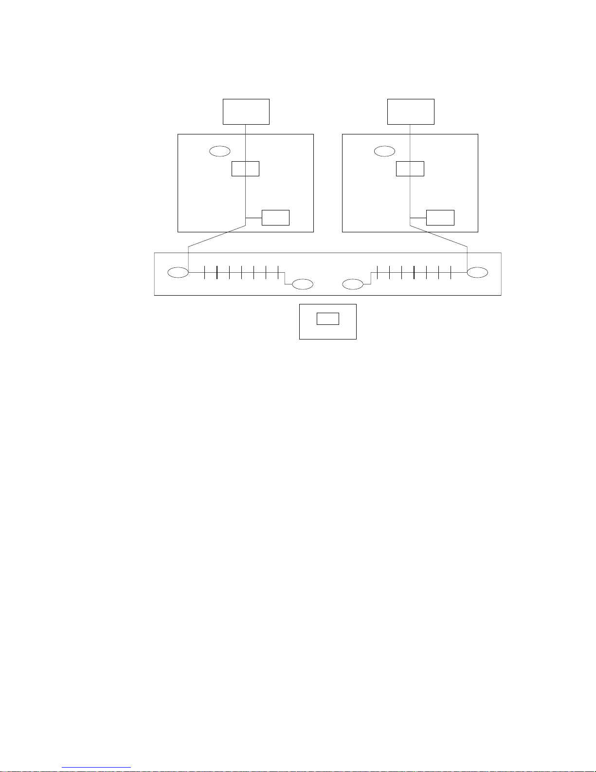
Notes:
1. The two Host Bus Adapters cannot have the same SCSI address.
2. Disk drive slots 6 and 7 (SCSI IDs 5 and 6) have dummy disk drive modules
installed in them.
Note: In this configuration, SCSI addresses 5 and 6 cannot be used for disk drive
modules.
Terminator Terminator
Backplane
Terminator Terminator
Terminators
12 disk drive modules
Repeater Repeater
Enclosure
service
processor
SCSI bus
bridge card
Enclosure
service
processor
Repeater
SCSI
interface
card
SCSI
interface
card
Host bus adapter (HBA)
ID:5 or 6
Host bus adapter (HBA)
ID:6 or 5
01234XX 891011121314
Figure 5. Single Bus, Two Initiators, 12 Disk Drive Modules
Chapter 1. Introduction 11
Page 20
Terminator Terminator
Backplane
Terminator Terminator
SCSI
interface
card
SCSI
interface
card
Host bus adapter (HBA)
ID:7
Host bus adapter (HBA)
ID:7
Terminators
7 disk drive modules 7 disk drive modules
Repeater Repeater
Enclosure
service
processor
SCSI bus
bridge card
Enclosure
service
processor
Repeater
0123456 891011121314
Figure 6. Dual Bus, Two Initiators, 14 (2 x 7) Disk Drive Modules
12 2104 Models DU3 and TU3 Hardware Technical Information
Page 21

Chapter 2. Product Characteristics
This section describes the physical characteristics of the 2104 Model DU3 and 2104
Model TU3, and their environmental and power requirements.
Dimensions
Model Height Width Depth
Model DU3 128 mm
(5.0 in.) 3 EIA units
445 mm
(18 in.)
552 mm max
(22 in.)
Model TU3 529 mm
(21 in.)
281 mm at foot
(11 in.)
594 mm
(23.5 in.)
Weight
The weight of a 2104 depends on its configuration.
Model Configuration Disk Drive Modules Weight
Model DU3 Minimum 1 23.0 kg (51 lb)
Maximum 14 38.5 kg (85 lb)
Model TU3 Minimum 1 39.6 kg (87 lb)
Maximum 14 54.5 kg (120 lb)
Service Clearances
Model Service Clearance
Model DU3 The minimum is 114 cm (45 in.) front and 81 cm (32 in.) rear when the 2104
is mounted in a rack
Model TU3 The minimum is 1 m (39 in.) front, back, and on each side.
13
Page 22

Environment
Temperature and Humidity
A 2104 has the following environmental limits:
Air Temperature Relative Humidity Maximum Wet Bulb
Operating 10°Cto40°C
(50°Fto104°F)
8% to 80%
noncondensing
27°C (80°F)
Recommended
operating point
22°C
(72°F)
45%
Recommended
operating range
20°Cto25°C
(68°Fto77°F)
40% to 50%
Nonoperating 10°Cto52°C
(50°Fto126°F)
8% to 80%
noncondensing
27°C (80°F)
Storing 1°Cto60°C
(34°Fto140°F)
5% to 80%
noncondensing
29°C (84°F)
Shipping −40°C to 60°C
(−40°F to 140°F)
5% to 100%
condensing but
not precipitating
29°C (84°F)
Notes:
1. The recommended operating temperature is 22°C (72°F) or lower. At lower
temperatures, the risk of failure in the unit is reduced. If the operating temperature
is above 22°C (72°F) for long periods of time, the 2104 is exposed to a greater risk
of failure from external causes.
2. The nonoperating environment must not exceed the operating environment limits for
longer than 60 days.
3. The storage environment must not exceed the operating environment limits for
longer than 1 year.
4. Substantial deviations from the recommended operating range, in either direction, if
sustained for extended periods of time, will expose the 2104 to greater risk of failure
from external causes.
Altitude
Altitude (from sea level) limits for both models are:
Operating: 0 to 2133 m (0 to 7000 ft)
Nonoperating: −304.8 m to 12 192 m (−1000 to 40 000 ft)
Note: The upper dry bulb temperature limit of the rack-mounted unit is lowered by 1°C
(2°F) for every 137 meters (450 feet) above 915 meters (3000 feet). The upper
wet bulb temperature limit is lowered by 1°C (2°F) for every 274 meters (900
feet) above 305 meters (1000 feet).
14 2104 Models DU3 and TU3 Hardware Technical Information
Page 23

Heat Output, Airflow, and Cooling
The maximum heat output of either model is 330 watts (1126 BTU/hr).
Each 2104 requires an airflow of 1.1 m³ ( 40 cubic feet) per minute.
When racks containing many 2104s are to be installed together, the following
requirements must be met to ensure that the 2104s are adequately cooled:
v The airflow is in at the front of the rack and out at the back. To avoid moving exhaust
air to the intake of another piece of equipment, racks should be positioned in
alternate rows, back-to-back and front-to-front.
v The front of racks should be positioned on floor-tile seams, with a full line of
perforated tiles immediately in front of the racks.
v Where racks are in rows front-to-front or back-to-back, there should be a gap of at
least 1220 mm (48 in) separating the rows.
v To ensure proper airflow within each rack, the rack filler plates must be installed in
unused positions. Also, all the gaps in the front of the racks must be sealed,
including the gaps between the 2104s.
Chapter 2. Product Characteristics 15
Page 24

Electrical Power
Electrical power is supplied to each 2104 by either one or two fan-and-power-supply
assemblies. These fan-and-power-supply assemblies convert the input voltage to dc for
distribution within the 2104.
One fan-and-power-supply assembly provides enough power for a fully populated 2104.
If two fan-and-power-supply assemblies are present in the 2104, each disk drive
module receives power from both fan-and-power-supply assemblies. If one
fan-and-power-supply assembly fails, all disk drive modules can continue to operate.
Input-voltage Requirements
Main AC Supply
Fan-and-power-supply assemblies can run uninterrupted with ac inputs from 90 to 260
volts and from 47 to 63 Hz.
The 2104 is designed to operate within the limits of power line disturbance given in the
table below.
Transient Voltage
(rms)
Duration Frequency Nominal Voltage (rms)
287 V 2.0 s 47 to 63 Hz 240 V
70 V 2.0 s 47 to 63 Hz 100 V
65 V 0.5 s 47 to 63 Hz 100 V
0 V 20 ms – 100 V
–48 Volts DC Supply
For Model DU3 units with the optional –48 V power supply feature, the input voltage
must be in the range –40Vto–60 V.
The 2104 is designed to operate within the limits of power line disturbance given in the
table below.
Transient Voltage Duration Frequency Nominal Voltage
–65 V dc 1.0 s N/A <=60 V dc
–38 V dc 2.0 s N/A >=40 V dc
–35 V dc 0.5 s N/A >=40 V dc
0 V dc 3 ms N/A >=40 V dc
Power Input
The following table shows the power input that is needed for a 2104. The values shown
are for a 2104 in which 14 disk drive modules are installed.
16 2104 Models DU3 and TU3 Hardware Technical Information
Page 25

Description Operating (100 disk ops per
second)
Two power supplies (100
disk ops per second)
100 VAC input 410 W 210 W each
240 VAC input 430 W 220 W each
Power Factor
Power factor correction is applied within the fan-and-power-supply assemblies of each
2104. This maintains the power factor of the unit at not less than 0.95 at 50% of
maximum load.
Output Protection
Each fan-and-power-supply assembly has over-current and over-voltage protection.
Early Power-Off Warning (EPOW)
Each fan-and-power-supply assembly provides an early power-off warning (EPOW)
signal to the controlling SCSI interface card. When both fan-and-power-supply
assemblies signal an EPOW, the controlling SCSI interface card signals an EPOW to
each disk drive within the 2104.
Chapter 2. Product Characteristics 17
Page 26

Power Control
Each fan-and-power-supply assembly in the 2104 has a DC On/Standby switch.
The power to the 2104 is also controlled by the Power Control switch on the switch
card.
Power Sequencing
The power sequencing of the disk drive modules in a 2104 is controlled by the settings
of the Drive Auto-Start and Select Enclosure Services switches on the switch card.
These are:
Drive Auto-Start switch Select Enclosure
Services switch
Power Sequence
OFF OFF Normal Start
ON OFF Command Start
OFF ON Delayed Start
ON ON Reserved
Auto Restart
2104s automatically restart when input power is restored within specification after a
power failure. The disk drive module motors start under the control of the using system.
18 2104 Models DU3 and TU3 Hardware Technical Information
Page 27

Safety Approvals
A 2104 Model DU3 or TU3 is certified to the following safety standards:
v IEC 60950 (International Electrotechnical Commission)
v EN 60950 (European Nom)
v CSA950/UL1950 Binational (CSA Underwriters Laboratories’ binational ITE standard)
Chapter 2. Product Characteristics 19
Page 28

Electromagnetic Compatibility
Federal Communications Commission (FCC) Statement
This equipment has been tested and found to comply with the limits for a Class A
digital device, pursuant to Part 15 of the FCC Rules. These limits are designed to
provide reasonable protection against harmful interference when the equipment is
operated in a commercial environment. This equipment generates, uses, and can
radiate radio frequency energy and, if not installed and used in accordance with the
instruction manual, may cause interference to radio communications. Operation of this
equipment in a residential area is likely to cause harmful interference, in which case the
user will be required to correct the interference at his own expense.
Properly shielded and grounded cables and connectors must be used in order to meet
FCC emission limits. Neither the provider nor the manufacturer is responsible for any
radio or television interference caused by using other than recommended cables and
connectors or by unauthorized changes or modifications to this equipment.
Unauthorized changes or modifications could void the user’s authority to operate the
equipment.
This device complies with Part 15 of FCC Rules. Operation is subject to the following
two conditions: (1) this device may not cause harmful interference, and (2) this device
must accept any interference received, including interference that may cause undesired
operation.
Japanese Voluntary Control Council for Interference (VCCI) Statement
This product is a Class A Information Technology Equipment and conforms to the
standards set by the Voluntary Control Council for Interference by Information
Technology Equipment (VCCI). In a domestic environment, this product might cause
radio interference, in which event the user might be required to take adequate
measures.
Korean Government Ministry of Communication (MOC) Statement
Please note that this device has been approved for business purposes with regard to
electromagnetic interference. If you find that this device is not suitable for your use, you
can exchange it for one that is approved for non-business purposes.
New Zealand Compliance Statement
This is a Class A product. In a domestic environment this product might cause radio
interference, in which event the user might be required to take adequate measures
International Electrotechnical Commission (IEC) Statement
This product has been designed and built to comply with (IEC) Standard 60950.
Avis de conformitéàla réglementation d’Industrie Canada
Cet appareil numérique de la classe A est conforme à la norme NMB-003 du Canada.
20 2104 Models DU3 and TU3 Hardware Technical Information
Page 29

Industry Canada Compliance Statement
This Class A digital apparatus complies with IECS-003.
United Kingdom Telecommunications Requirements
This apparatus is manufactured to the International Safety Standard EN60950 and as
such is approved in the U.K. under approval number NS/G/1234/J/100003 for indirect
connection to public telecommunications systems in the United Kingdom.
European Union (EU) Statement
This product is in conformity with the protection requirements of EU council directive
89/336/EEC on the approximation of the laws of the Member States relating to
electromagnetic compatibility. Neither the provider nor the manufacturer can accept
responsibility for any failure to satisfy the protection requirements resulting from a
non-recommended modification of the product, including the fitting of option cards not
supplied by the manufacturer.
This product is in conformity with the EU council directive 73/23/EEC on the
approximation of the laws of the Member States relating to electrical equipment
designed for use within certain voltage limits. This conformity is based on compliance
with the following harmonized standard: EN60950.
Radio Protection for Germany
Zulassungsbescheinigung laut dem Deutschen Gesetz über die
elektromagnetische Verträglichkeit von Geräten (EMVG) vom 30. August 1995
(bzw. der EMC EG Richtlinie 89/336):
Dieses Gerät ist berechtigt in Übereinstimmung mit dem Deutschen EMVG das
EG-Konformitätszeichen - CE - zu führen. Verantwortlich für die Konformitätserklärung
nach Paragraph 5 des EMVG ist die:
IBM Deutschland Informationssysteme GmbH, 70548 Stuttgart.
Informationen in Hinsicht EMVG Paragraph 3 Abs. (2) :
Das Gerät erfüllt die Schutzanforderungen nach EN 50082-1 und EN 55022 Klasse A.
EN 55022 Klasse A Geräte müssen mit folgendem Warnhinweis versehen werden:
″Warnung: dies ist eine Einrichtung der Klasse A. Diese Einrichtung kann im
Wohnbereich Funkstörungen verursachen; in diesem Fall kann vom Betreiber verlangt
werden, angemessene Massnahmen durchzuführen und dafür aufzukommen.″
EN 50082-1 Hinweis:
″Wird dieses Gerät in einer industriellen Umgebung betrieben (wie in EN 50082-2
festgelegt), dann kann es dabei eventuell gestört werden. In solch einem Fall ist der
Abstand bzw. die Abschirmung zu der industriellen Störquelle zu vergrössern.″
Anmerkung:
Um die Einhaltung des EMVG sicherzustellen sind die Geräte, wie in den Handbüchern
angegeben, zu installieren und zu betreiben.
Chapter 2. Product Characteristics 21
Page 30

Taiwan Class A Compliance Statement
22 2104 Models DU3 and TU3 Hardware Technical Information
Page 31

Chapter 3. Physical Connections
Figure 7 shows the external connectors of the 2104 Model DU3. 1 are SCSI
connectors and 2 are mainline power connectors.
Figure 7. Back of a 2104 Model DU3 Showing External Connectors
23
Page 32

Figure 8 shows the external connectors of the 2104 Model TU3. 1 are mainline power
connectors and 2 are SCSI connectors.
This section provides information about these connectors.
Figure 8. Back of a 2104 Model TU3 Showing External Connectors
24 2104 Models DU3 and TU3 Hardware Technical Information
Page 33

SCSI Adapters and Cables
An RS/6000 or IBM
server
pSeries computer uses one of the following SCSI
adapters to connect to the 2104 Model DU3 or 2104 Model TU3:
v PCI 3-Channel Ultra2 SCSI RAID Adapter (Feature Code 2494 Type Number 4-T)
v PCI Dual Channel Ultra2 SCSI Adapter (Feature Code 6205 Type Number 4-R)
v PCI Single-Ended Ultra SCSI Adapter (Feature Code 6206 Type Number 4-K)
v PCI Single-Ended Plus SCSI RAID Adapter (Feature Code 6208 Type Number 4_A)
v PCI 4–Channel Ultra3 SCSI RAID Adapter/A (Feature Code 2498 Type Number 4-X)
The SCSI cables supported by these adapters are:
Adapter (Feature
Code)
Cable Length Feature Code Part Number
6205 or 2494 20 meters 9320 09L3307
10 meters 9310 09L3305
5 meters 9305 09L3303
3 meters 9303 09L3301
1 meter 9301 09L3299
6206 or 2493 3 meters 9313 09L3309
2415 3 meters 9323 09L3311
Please obtain the latest product information from the following IBM Web address:
www.ibm.com/storage
Chapter 3. Physical Connections 25
Page 34
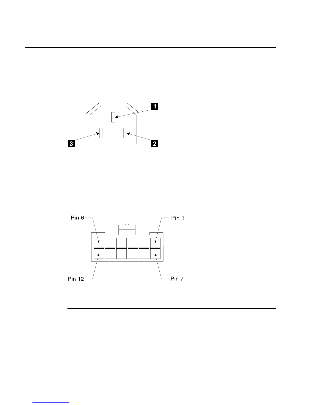
Mainline-Power Connectors
Main AC Power Supply on a 2104 Model DU3 or 2104 Model TU3
A mainline-power connector is on each fan-and-power-supply assembly. The connector
is a 10-amp, three-pin, polarized, IEC 320 input connector. See Figure 9, in which 1 is
the ground connection, 2 is the neutral connection, and 3 is the live connection.
–48 V Power Supply
There is one –48 V power connector on each fan-and-power-supply assembly in a 2104
Model DU3 that has this optional feature. This permits the 2104 to be connected to the
–48 V dc rack power distribution panel. The connector is a 12–pin connector (see
Figure 10).
Pin Assignment Pin Assignment
1 Frame ground 7 Frame ground
2 Not used 8 Not used
3 –48 V return (0 V) 9 –48 V return (0 V)
4 –48 V return (0 V) 10 –48 V return (0 V)
5 –48Vin 11 –48Vin
6 –48Vin 12 –48Vin
Figure 9. AC Mainline-Power Connector
Figure 10. –48 V Power Connector (Viewed from the Back of the 2104)
26 2104 Models DU3 and TU3 Hardware Technical Information
Page 35

Page 36

Part Number: 07K8063
Printed in the U.S.A.
SA33-3309-00
(1P) P/N: 07K8063
 Loading...