

Page 1
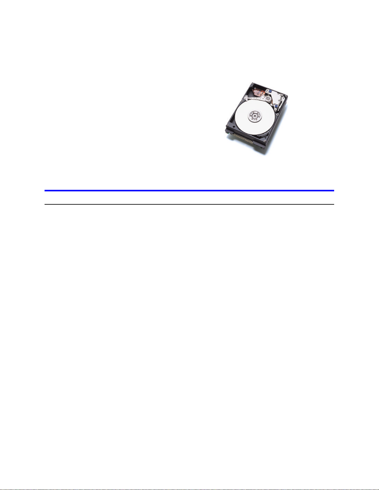
IBM storage products
Installation guide
Travelstar 25GS, 18GT,
& 12GN
ATA/IDE
DARA-218000DARA-225000Model:
DARA-212000DARA-215000
DARA-206000DARA-209000
Introduction
IBM
Thank you for purchasing an IBM advanced-technology Travelstar hard disk drive. By purchasing
this drive, you acknowledge the following:
Ÿ you have read and agreed to the conditions listed on the ShopIBM Web site
Ÿ you are a system integrator with the necessary knowledge to install IBM DARA-2xxxxx hard
drives
Ÿ you understand that the system into which you will be installing the IBM DARA-2xxxxx drive
must be capable of supporting hard drives of 8 GB or greater capacity with or without BIOS
upgrades
For successful installation please note the following:
Ÿ The drive must be left in its protective anti-static bag and shipping box until you are ready to
install it.
Ÿ Retain the shipping box and all packaging materials after installation. This box has been
designed to ensure safe shipment of the drive.
Ÿ This drive does not come with any installation screws, brackets, cabling, or software. You may
need special brackets and other items to successfully install this drive.
This document is subject to change without notice.
Page 1
IBM Technology Group Support Center version 1.0
Page 2
IBM storage products
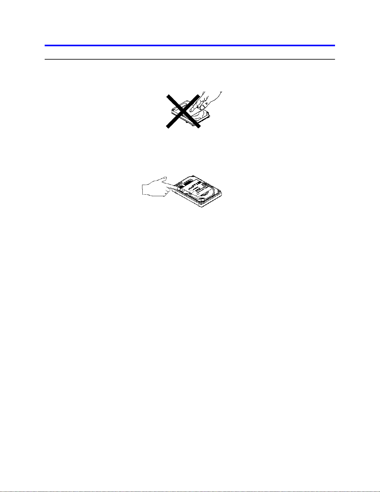
Handling precautions
Ÿ Do not apply pressure on the drive during handling or installation.
Ÿ Do not cover the breather hole! Covering the breather hole may result in loss of
data.
Ÿ Always handle the drive with care to prevent damage from shock, vibration, or
electrostatic discharge.
Ÿ Handle the drive carefully by the edges. Do not touch any exposed printed circuit
board.
Page 2
IBM Technology Group Support Center version 1.0
Page 3

IBM storage products
BIOS settings for DARA-225000, DARA-218000, DARA-215000, DARA-212000, and DARA-209000
IMPORTANT: Please read this entire BIOS settings section before you begin installation.
Before you begin installation, make sure that the system into which you will be installing this drive has a
BIOS capable of supporting a hard drive of 8.4 GB or greater capacity. Some older system BIOS may
have difficulty recognizing a drive of this capacity and configuration at initial power on. Some BIOS may
simply need to be upgraded in order to accept a hard drive of 8.4 GB or greater capacity. There are
software programs, such as Disk Manager, that can help upgrade the BIOS by replacing the disk drive
driver software of the system BIOS with a software driver that will allow the system to function with drives
of larger capacity. A software program such as Disk Manager installs the driver which enables use of the
full capacity of the drive. The Disk Manager software program can be downloaded from the IBM Web
site at the following address:
http://www.storage.ibm.com/techsup/hddtech/welcome.htm
If you are unsure about the capability of your system BIOS to support this hard drive, you may download
Disk Manager onto a floppy disk before you begin drive installation.
the system allows BIOS access
If
If the system allows access to its BIOS settings, set the disk drive setting in the BIOS to AUTO.
the system boots up but does not support or properly recognize the new drive capacity
If
Some older BIOS will allow the system to boot up but not recognize a drive of 8.4 GB or higher
capacity. Some BIOS will allow the system to boot up but will only recognize the drive as having a
very low capacity. In this case, you may download the Disk Manager software program from the IBM
Web site address shown above, to replace the disk drive driver software of the system’s BIOS with a
software driver that will allow the system to use the drive’s full capacity.
the system locks up and will not boot up
If
Some older systems do not recognize hard drives with 16 heads. In this case, as the system
integrator/ drive installer, you may either upgrade the system BIOS to accept a 16-head drive or install
a drive of lower capacity.
Customers who experience problems installing this drive in a system may contact
IBM Technology Group Support Center
888.426.5214 (toll-free in the United States) or 507.286.5825
drive@us.ibm.com
Page 3
IBM Technology Group Support Center version 1.0
Page 4

IBM storage products
Mounting hole location
The location and size of the mounting holes are shown below. All dimensions are in millimeters unless
noted otherwise.
Page 4
IBM Technology Group Support Center version 1.0
Page 5

–300 to 12,000 m (40,000 ft)
–300 to 3,000 m (10,000 ft)
Altitude
20°C per hour
20°C per hour
Maximum temperature gradient
–40 to 65°C
5 to 55°C
Temperature range
40.0°C (non-condensing)
29.4°C (non-condensing)
Maximum wet bulb temperature
Nonoperating Conditions
Operating Conditions
Pin
IBM storage products
Mounting orientation
The drive will operate in all six (6) axes. The drive will operate within the specified error rates when tilted
±5 degrees from these positions. Performance and error rates will stay within specification limits if the
drive is operated in the other permissible orientations from which it was formatted. Thus, a drive formatted in a horizontal orientation will be able to run vertically and vice versa.
The recommended mounting screw thread length is 3.0 mm for bottom mounitng and 3.5 mm for horizontal mounting.
The system integrator is responsible for mounting the drive securely using appropriate screws or equivalent mounting hardware to prevent excessive motion or vibration of the drive during seek operation or
spindle rotation.
Environmental characteristics
The system must provide sufficient air movement to maintain a surface temperature below 60°C at the
center of the top cover and below 63°C at the center of the card of the drive
.
Refer to the separate data sheet enclosed with this disk drive for additional specifications.
Interface connector
43
44
Pin
19
22
1
AC
2
D
B
Note: Pin position 20 is left blank for correct connector insertion. Pin positions A, B, and D are used for
drive address setting.
Operating mode at power on
The device goes to idle mode after power on or hard reset as an initial state. Initial state may be
changed to Standby mode using pin C on the interface connector.
IBM Technology Group Support Center version 1.0
Page 5
Page 6

39
DA02
36
35
32
31
28
IORDY(*
27
24
–
DIOW(*
23
Key
(20)
GND
19
16
15
12
11
08
DD05
07
04
03
–DIOW
STOP
–DIOW
STOP
definition
Ultra DMA)
. "Reserve" designates reserved pins that must be left unconnected.
IBM storage products
Signal definition
The pin assignments of interface signals are listed in the following table
01
TTLI–RESET
3-stateI/ODD07
05
3-stateI/ODD06
06
3-stateI/O
09
3-stateI/ODD04
10
3-stateI/ODD03
13
3-stateI/ODD02
14
3-stateI/ODD01
17
21
3-stateI/ODD00
3-stateODMARQ
18
22
TTLI
25
–DIOR(*
TTLI
26
ODO
29
TTLI–DMACK
30
3-stateOINTRQ
33
TTLIDA01
34
TTLIDA00
37
41
+5V
TTLI–CS0
(reserve)44ground43
:
GND02
GND
GND
GND
GND
–CS138
GND40ODI/O–DASP
TypeI/OSIGNALPINTypeI/OSIGNALPIN
3-stateI/ODD08
3-stateI/ODD09
3-stateI/ODD10
3-stateI/ODD11
3-stateI/ODD12
3-stateI/ODD13
3-stateI/ODD14
3-stateI/ODD15
TTLICSEL
ODO–HIOCS16
ODI/O–PDIAG
TTLI
TTLI
power+5V motor42power
Notes:
1. "O" designates an output from the Drive.
2. "I" designates an input to the Drive.
3. "I/O" designates an input/output common.
4. "OD" designates Open-Drain output.
5. The signal lines marked with (*) are redefined during the Ultra DMA protocol to provide special functions. These lines change from the conventional to special definitions at the moment the Host decides to allow a DMA burst if the Ultra DMA transfer mode was previously chosen via SetFeatures.
The Drive becomes aware of this change upon assertion of the –DMACK line. These lines revert
back to their original definitions upon the deassertion of –DMACK at the termination of the DMA
burst.
Conventional
IORDY
–DIOR
–DIOR
IORDY
Write
operation
Read
operation
Special definition (for
–DDMARDY
HSTROBE
–HDMARDY
DSTROBE
6. "Power" designates a power supply to the drive.
7
Page 6
IBM Technology Group Support Center version 1.0
Page 7

IBM storage products
Setting the drive address
The drive address is determined by the placement of jumpers on the pins on the right side of the interface
connector as shown below. The default setting at shipment is for Device 0.
If Cable Select is chosen, the drive address depends on the state of pin 28 (see illustration on page 3) of
the AT interface cable. If pin 28 is ground or low, the drive is a Device 0. If pin 28 is open or high, the
drive is a Device 1.
No Jumper
(Master)
Jumper Pos-1
(Slave)
Jumper Pos-3
(Cable Select)
Never Attach A
Jumper Here!
Never Attach A
Jumper Here!
Data loss on power off
Ÿ The drive retains recorded data under all non-write operations.
Ÿ No more than one sector can be lost by power down during write operation while write cache is dis-
abled.
Ÿ Power off during a write operation may create an incomplete sector which will report a hard data er-
ror when read. The sector can be recovered by a rewrite operation.
Ÿ A hard reset does not cause any data loss.
Electromagnetic compatibility
The drive, when installed in a suitable enclosure and exercised with a random accessing routine at maximum data rate, meets the following worldwide EMC requirements:
Ÿ United States Federal Communications Commission (FCC) Rules and Regulations (Class B), Part
15.
Ÿ European Economic Community (EEC) directive number 76/889 related to the control of radio fre-
quency interference and the Verband Deutscher Elektrotechniker (VDE) requirements of Germany
(GOP).
IBM will provide technical support to assist users in complying with the EMC requirements
.
Safety
This product does not contain any known or suspected carcinogens.
This product meets or exceeds all applicable government environmental regulations in the country of
origin. None of the packaging used for the shipment of the product uses controlled CFCs in the
Page 7
IBM Technology Group Support Center version 1.0
Page 8

IBM storage products
manufacturing process. None of the manufacturing processes for disk drive parts or assemblies, including printed circuit boards, use controlled CFC materials.
Page 8
IBM Technology Group Support Center version 1.0
Page 9

IBM storage products
ibm®
© International Business Machines Corporation 2000
www.ibm.com/harddrive
IBM Technology Group Support Center
Telephone: 888.426.5214 or 507.286.5825
E-mail: drive@us.ibm.com
Singapore Technology Group Support Center
Telephone: (65)6418.9595 or 1800.418.9595
E-mail: drive@sg.ibm.com
UK Technology Group Support Center
Telephone: 44.1475.898.125
E-mail: drive@uk.ibm.com
Germany Technology Group Support Center
Telephone: 49.7032.153050
E-mail: drive@de.ibm.com
Printed in the United States of America
08-2000
All Rights Reserved
Other company, product, and service names may be trademarks or service marks of others.
Produced by the IBM Technology Group Support Center.
OEM Hard Disk Drive Specifications for DARA-2xxxxx (6GB - 25GB) 2.5 inch hard disk
drive with ATA interface, Revision 2.1
This document is not a substitute for the full production specification, which should be used
when detailed information is required.
Data is subject to change without notice.
Date: 1st August, 2000
Page 9
IBM Technology Group Support Center version 1.0
 Loading...