

Page 1

CTI 2572
ETHERNET TCP/IP MODULE
INSTALLATION AND OPERATION GUIDE
Version 2.4
CTI Part # 062-00146-024
2572IOG 100901 $25
Page 2

Page 3

Copyright 2001 Control Technology Inc.
All rights reserved.
This manual is published by Control Technology Inc., 5734 Middlebrook Pike, Knoxville, TN 37921.
This manual contains references to brand and product names which are tradenames, trademarks,
and/or registered trademarks of Control Technology Inc. and Siemens AG. Other references to brand
and product names are tradenames, trademarks, and/or registered trademarks of their respective
holders.
DOCUMENT DISCLAIMER STATEMENT
Every effort has been made to ensure the accuracy of this document; however, errors do occasionally
occur. CTI provides this document on an “as is” basis and assumes no responsibility for direct or
consequential damages resulting from the use of this document. This document is provided without
express or implied warranty of any kind, including but not limited to the warranties of
merchantability or fitness for a particular purpose. This document and the products it references are
subject to change without notice. If you have a comment or discover an error, please call us toll-free
at 1-800-537-8398.
REVISION HISTORY
V1.0 2/24/94 Original Release
V1.1 5/27/94 Revised PLC Ladder Example.
Revised Start Network Server command block.
Added EEPROM Write/Read command blocks.
Incorporated miscellaneous minor additions and corrections.
V1.2 9/11/94 Added fields to Start Network Server command block which control TCP/IP
connections.
Added an Error Code Appendix
Incorporated minor additions and corrections.
V1.3 2/10/95 Expanded error code and troubleshooting documentation.
Provided more information about the PLC Command Interface.
V2.0 5/1/95 Incorporated Client Commands from 2572 Programmers Reference Manual.
V2.1 10/12/95 Documented Create Socket Startup Option bit to set client priority.
Added note re: handling of lost TCP connections.
Incorporated miscellaneous minor additions and corrections.
V2.2 3/11/98 Documented Memory Exchange Command.
Added Subnet Address mask and TCP Stale Socket timeout.
Added UDP Option to include IP address in Memory Transfer commands.
Added Appendix D – PLC Command Interface.
Added Appendix E – Moved IP Nomenclature to this appendix.
Expanded troubleshooting section.
V2.3 3/28/00 Changed examples to use a “private” IP address specified in RFC 1597
Corrected minor typos and added notes for clarification.
Revised ladder logic example for client application.
CTI 2572 Installation and Operation Gui de
i
Page 4

REVISION HISTORY
V2.4 10/9/01 Incorporated addendum material
Revised Uncoupled Mode description to indicate that Command Block
would not be re-read if the Command Trigger were held high.
Corrected typographical errors
ii
CTI 2572 Installation and Operation Gui de
Page 5

PREFACE
This Installation and Operation Guide provides installation and operation instructions for the CTI
2572 Ethernet TCP/IP Adapter Module. The information in this manual is directed to individuals
who will be installing, maintaining, and troubleshooting the module.
We assume you are familiar with the installation and operation of:
1) SIMATIC 505 programmable controllers,
2) Ethernet local area networks,
3) Transmission Control Protocol/Internet Protocol.
Please refer to the appropriate SIMATIC user documentation for specific information on SIMATIC
505 programmable controllers and I/O modules.
If you plan on developing on writing computer applications which interface to the module via TCP/IP
you should also obtain the CTI 2572 Programming Reference Manual (CTI Part # 62-166), which
provides detailed information on the module command message interface.
CTI 2572 Installation and Operation Gui de
iii
Page 6

USAGE CONVENTIONS
NOTE:
Notes alert the user to special features or procedures.
CAUTION:
Cautions alert the user to procedures that could damage equipment.
WARNING:
Warnings alert the user to procedures that could damage equipment and endanger the user.
iv
CTI 2572 Installation and Operation Gui de
Page 7

TABLE OF CONTENTS
CHAPTER 1. DE S CRIPTION..................................................................................1
1.1. Introduction...........................................................................................................1
1.2. Ethernet Ports......................................................................................................2
1.3. Serial Ports...........................................................................................................3
1.4. LED Indicators......................................................................................................4
1.5. Functional Overview.............................................................................................5
1.6. TCP/IP Overview..................................................................................................7
1.7. PLC Command Interface.....................................................................................8
1.8. Getting Started.....................................................................................................9
CHAPTER 2. INS TALL ATION...............................................................................11
2.1. Installation Planning...........................................................................................11
2.2. Power Requirements .........................................................................................12
2.3. Unpacking the Module.......................................................................................13
2.4. Setting the 2572 Switches .................................................................................14
2.5. Physical Installation............................................................................................17
2.6. Using PLC Logic to Start the Network Server...................................................19
2.7. Automatically Starting the Network Server........................................................25
2.8. Connecting Cables.............................................................................................26
2.9. Module Checkout...............................................................................................27
CHAPTER 3. MODU L E OPERA TION...................................................................29
3.1. General Module Operation ................................................................................29
3.2. Ethernet TCP/IP Operation................................................................................29
3.3. Serial Port Operation..........................................................................................30
3.4. Serial Redirect Operation...................................................................................30
CHAPTER 4. CAMP CLIE N T COMMA N DS..........................................................31
4.1. Overview ............................................................................................................31
4.2. Create Socket Command..................................................................................31
4.3. Close Socket Command....................................................................................34
4.4. Memory Transfer Commands ...........................................................................34
4.5. Application Example ..........................................................................................40
CHAPTER 5. SE N D-RECEIVE P ROTOCOL........................................................ 49
5.1. Overview ............................................................................................................49
5.2. Implementation ..................................................................................................49
5.3. Send/Receive Command Blocks.......................................................................51
5.4. Application Example ..........................................................................................56
CHAPTER 6. DATASHARE PROTOCOL.............................................................65
6.1. Overview ............................................................................................................65
6.2. Implementation ..................................................................................................66
6.3. PLC Command Blocks......................................................................................67
6.4. Master Controller Update Example ...................................................................71
6.5. Peer to Peer Update Example...........................................................................73
CTI 2572 Installation and Operation Gui de
v
Page 8

CHAPTER 7. E-MAIL FEATUR E...........................................................................77
7.1. Overview............................................................................................................77
7.2. 2572 Command Block .......................................................................................78
7.3. Application Example ..........................................................................................79
CHAPTER 8. T R OUBLESHOOT IN G....................................................................83
8.1. General Troubleshooting Techniques...............................................................83
8.2. General Module Problems.................................................................................84
8.3. Network Communications Problems.................................................................85
8.4. Serial Communications Problems.....................................................................87
8.5. PLC Logic Problems..........................................................................................89
8.6. Development and Debugging Tips....................................................................90
APPE NDIX A. 2572 CONNECTOR S ....................................................................93
RS-232 Connector (Port 1)........................................................................................93
RS-422 Connector (Port 2)........................................................................................93
10BaseT Connector...................................................................................................94
AUI Connector ...........................................................................................................94
AUI Power..................................................................................................................94
APPENDIX B. ERR OR CODES...........................................................................95
2572 System Error Codes .........................................................................................95
General Memory Transfer Error Codes.....................................................................98
PLC Server Error Codes..........................................................................................102
PLC Client Error Codes ...........................................................................................107
E-Mail Error Codes ..................................................................................................113
Send Receive Error Codes......................................................................................115
DataShare Error Codes...........................................................................................116
APPENDIX C. REF E RENCE MATERIAL .......................................................... 119
Hexadecimal to ASCII Conversion Table................................................................119
Monitoring the AUI/10BaseT Bit. .............................................................................120
Writing Network Parameters to EEPROM (PLC Method) ......................................120
Reading Network Parameters from EEPROM (PLC Method)................................122
APPENDIX D. PLC C OMMAND IN TERFACE................................................... 123
General Description.................................................................................................123
WX/WY Description.................................................................................................125
WX/WY Quick Reference........................................................................................132
Command Timing Diagrams ...................................................................................133
APPENDIX E. IP ADDRESS INFORMATION....................................................139
IP Address Nomenclature........................................................................................139
Private IP Addresses ...............................................................................................140
Subnet Mask............................................................................................................140
Port Number.............................................................................................................141
HARDWARE SPECIFICA TIONS.........................................................................143
LIMITED PRODUCT WARRANTY......................................................................145
REPAIR POLICY.................................................................................................147
vi
CTI 2572 Installation and Operation Gui de
Page 9

TABLE OF FIGURES
Figure 1. 2572 Front Panel................................................................................................. 1
Figure 2. 2572 Ethernet Ports ............................................................................................ 2
Figure 3. 2572 Serial Ports.................................................................................................. 3
Figure 4. LED Indicators..................................................................................................... 4
Figure 5. PLC Server Function........................................................................................... 5
Figure 6. PLC Client Function............................................................................................. 6
Figure 7. 2572 PLC Interface ............................................................................................. 8
Figure 8. 2572 Switch Locations....................................................................................... 14
Figure 9. Switchblock 1.................................................................................................... 14
Figure 10. Switchblock 2.................................................................................................... 15
Figure 11. Sample I/O Configuration................................................................................. 18
Figure 12. Representing IP Address in Hexadecimal Format............................................ 23
Figure 13. PLC Logic Example.......................................................................................... 24
Figure 14. 10BaseT Connection........................................................................................ 26
Figure 15. AUI Connection................................................................................................ 26
Figure 16. RS-232 Connector Pin-Out............................................................................... 93
Figure 17. RS-422 Connector............................................................................................ 93
Figure 18. 10BaseT Connector ......................................................................................... 94
Figure 19. AUI Connector.................................................................................................. 94
Figure 20. AUI Power Connector....................................................................................... 94
Figure 21. PLC Command Interface ................................................................................ 123
Figure 22. WX/WY Map .................................................................................................. 125
Figure 23. Coupled Mode Timing.................................................................................... 133
Figure 24. Uncoupled Mode Timing................................................................................. 134
Figure 25. Command Error Timing.................................................................................. 135
Figure 26. PLC Error Timing............................................................................................ 136
Figure 27. Command Abort Timing.................................................................................. 137
CTI 2572 Installation and Operation Gui de
vii
Page 10

Page 11
CHAPTER 1. DESCRIPTION
1.1. Introduction
The CTI 2572 Ethernet TCP/IP Adapter is a single
wide I/O module for SIMATIC 505 controllers. The
2572 module connects to Ethernet local area networks,
enabling the PLC to communicate with other network
stations using the Transmission Control Protocol/
Internet Protocol (TCP/IP). Using the CTI 2572
facilities, suitably programmed network stations can
acquire data from the PLC, send data and programs to
the PLC, and exercise supervisory control over the
PLC operation. In addition, the PLC can use the CTI
2572 to access data in other PLC systems equipped
with a CTI 2572.
The 2572 attaches to all Ethernet media specified by
IEEE 802.3 including 10Base5 ("thick" coaxial cable),
10Base2 ("thin" coaxial cable), 10BaseT (unshielded
twisted pair cabling), FOIRL (fiber optic cable) and
10BaseFL (fiber optic cable). 10BaseT cabling can be
attached directly to the 2572 via an RJ-45 connector.
Other IEEE 802.3 media may be connected to the AUI
(Attachment Unit Interface) port via a user supplied
transceiver.
The 2572 module also provides two serial ports that
can be used for configuration and diagnostic activities.
Both serial ports can operate concurrently.
The 2572 module itself requires no customer
programming. All configuration options can be set by
module switches or written to module EEPROM via a
serially attached personal computer. Optionally, PLC
logic can be used to set module configuration and to
control the operation of the module.
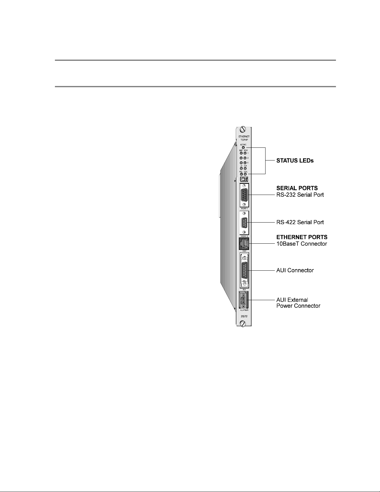
Figure 1. 2572 Front Panel
CTI 2572 Installation and Operation Gui de
1
Page 12
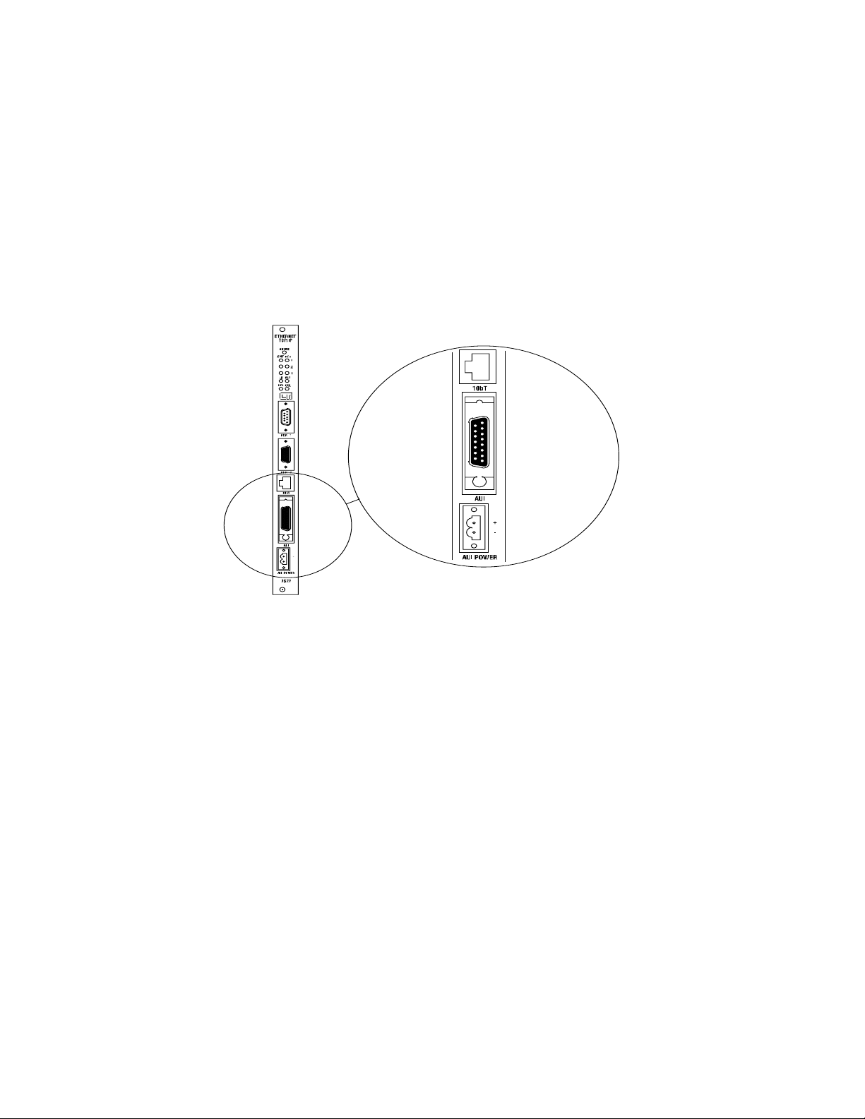
1.2. Ethernet Ports
The 2572 provides an IEEE 802.3 10BaseT port and an IEEE 802.3 AUI port. The 10BaseT port
connects to Unshielded Twisted Pair (UTP) cable using an RJ-45 connector. The 15-pin AUI
connector is used to attach a transceiver to the 2572. The transceiver, in turn, connects to the desired
Ethernet medium. Different transceivers are available for the various 802.3 media. Thus, using a
transceiver, the 2572 can connect to coaxial, UTP, or fiber optic cable.
Only one of the Ethernet ports is active at a time. The 2572 module automatically selects the port to
Figure 2. 2572 Ethernet Ports
be used based on the signal received. If a signal known as a link beat is detected on the 10BaseT
port, then the 10BaseT port will be selected. If a link beat is not detected on the 10BaseT port, then
the AUI port will be selected.
The auto-selection feature allows you to run redundant cabling, if you wish. If the link beat is lost on
the primary 10BaseT port (typically indicating a cable problem), the 2572 will automatically switch
over to the AUI port. When the link beat returns on the 10BaseT port, the module will switch back
to the 10baseT port. A bit in the Module Status Word can be used by PLC logic to monitor which
port is active. If bit 6 is on, then the AUI port is selected; if the bit is off, then the 10BaseT port is
selected. See Appendix C for more information.
Ethernet transceivers are typically powered from the AUI port. The 2572 will supply the AUI port
with power derived from the PLC backplane. In certain configurations, however, you may wish to
conserve backplane power. For these circumstances, the 2572 module provides a connector that
allows you to attach an external 12 VDC power supply. The external power supply can then supply
power to the AUI port. Refer to Chapter 2 of this manual for installation details.
2
CTI 2572 Installation and Operation Gui de
Page 13
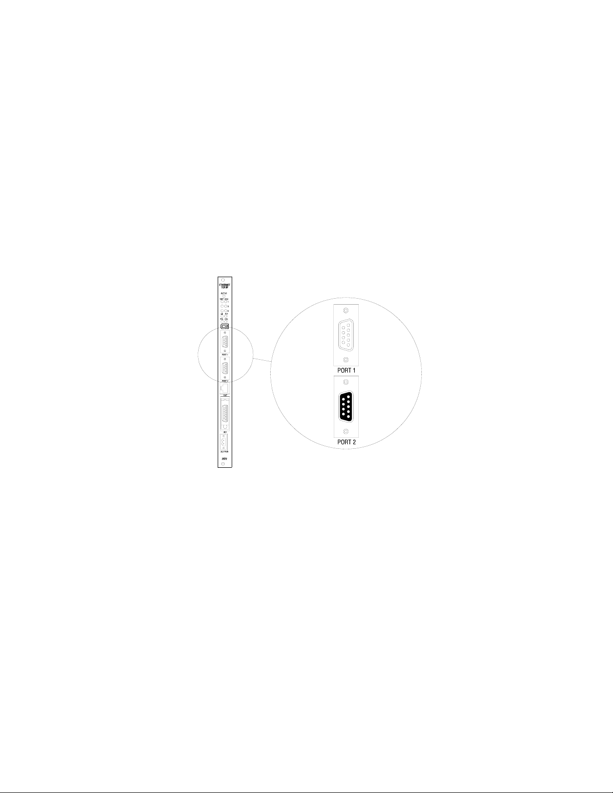
1.3. Serial Ports
The 2572 is equipped with two serial ports. These ports are provided for use with module
configuration and diagnostic programs. In addition, the ports may be used to access the local PLC.
Devices that communicate with the PLC using the Non Intelligent Terminal Protocol (NITP) can
access the PLC processor as if they were directly connected to the PLC program port.
Optionally, NITP commands sent to a serial port can be redirected to another node on the TCP/IP
network. Using this feature, PLC programming software program running on a PC connected to a
2572 serial port can perform remote programming on another PLC on the network. This feature
might be used where a programming tool that uses TCP/IP (such as SoftShop programming software)
is not available.
Port 1 uses a male DB9 connector to provide a subset of RS-232C. Port 2 provides an RS-422
electrical interface using a female DB9 connector. Since the pin configurations of the ports match
those of SIMATIC TI545 PLCs and the 2571 Programming Port Expander module, standard cables
can be used. The ports may be configured via switches for baud rates of 1200, 2400, 9600, or
19,200. Optionally, PLC logic can be used to set the communications parameters for the ports. Both
ports can operate concurrently with the Ethernet port; however, heavy serial port activity may
degrade network performance. See Appendix A for a diagram showing the port pin configurations.
Figure 3. 2572 Serial Ports
CTI 2572 Installation and Operation Gui de
3
Page 14
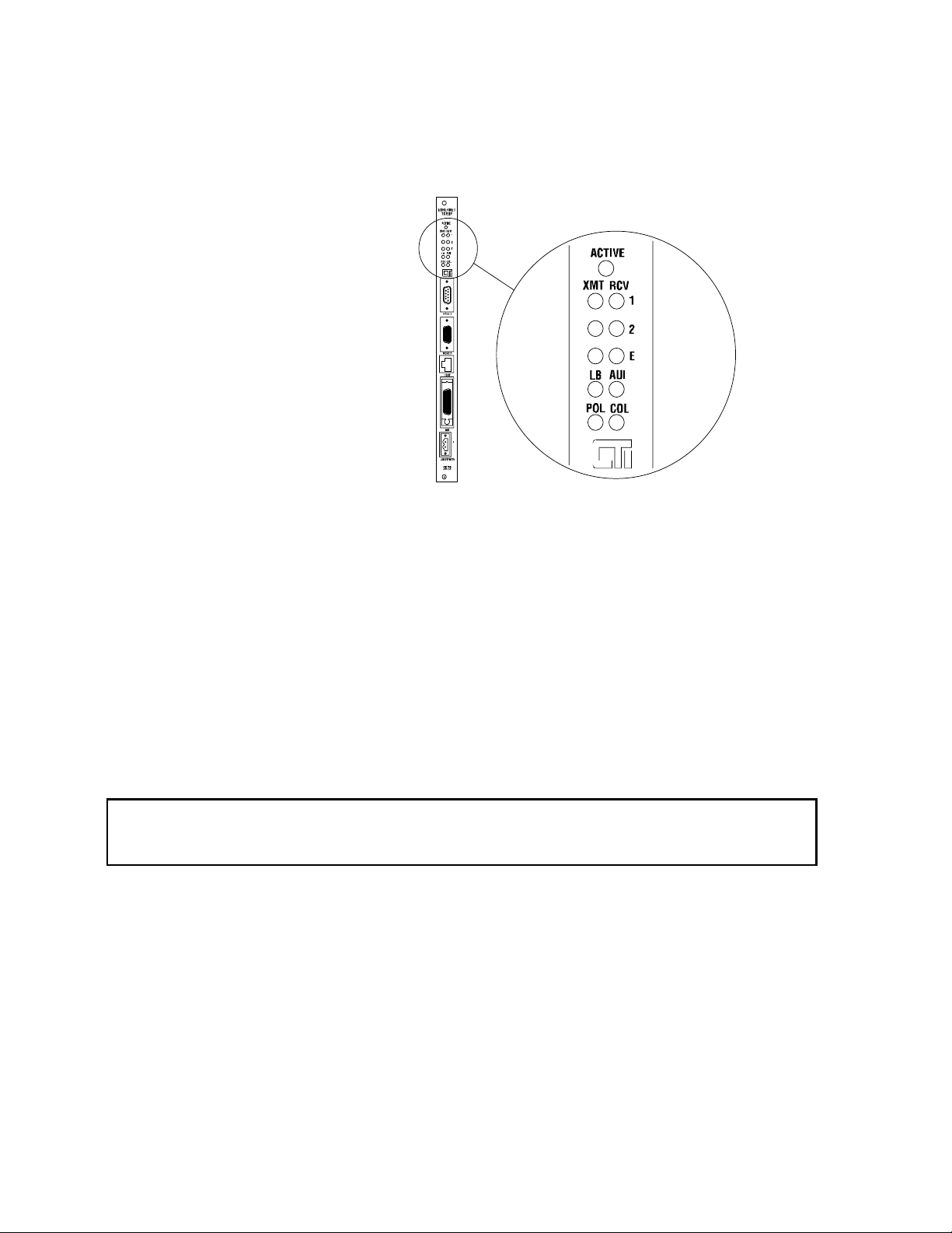
1.4. LED Indicators
The 2572 provides an array of LEDs that
inform the user of the module status and
communications activity. The functions
of the LEDs are described below:
ACTIVE Active Status. Indicates
the status of the module
hardware. Solid
illumination indicates the
module status is good.
Slow blinking indicates
the module has detected
a fault condition. Rapid
blinking indicates that
the network parameters
have not been set or are
invalid.
XMT Transmit. There is one LED each for Serial Port 1, Serial Port 2, and Ethernet,
which lights when data is transmitted on the applicable port.
RCV Receive. There is one LED each for Serial Port 1, Serial Port 2, and Ethernet. These
LEDs will light when a signal is received on the applicable port. The Ethernet LED
will flash when any network traffic is detected, not just valid packets or packets
addressed to the module.
Figure 4. LED Indicators
LB Link Beat. Indicates that a link beat signal is being received on the 10BaseT port and
that the 10BaseT port is selected. This LED should be lit if 10BaseT is being used.
AUI Attachment Unit Interface. Lights to indicate that the AUI port is selected for
Ethernet communications. If a link beat is not detected on the 10BaseT port, the
AUI port will be automatically selected.
NOTE:
The fact that the AUI LED is lit does not indicate that the attached transceiver is operating properly.
POL Polarity Reversed. Lights when the polarity for the UTP cable connected to the
10BaseT port has been reversed. This is a warning only, since the 2572 hardware
will correct for reversed polarity.
COL Collision. Lights when a collision is detected. Some collisions are normal when
using Ethernet. Excessive collision activity may indicate faulty cable termination,
defective transceivers, or an overloaded network.
4
CTI 2572 Installation and Operation Gui de
Page 15
1.5. Functional Overview
The 2572 can operate as both a PLC server and a PLC client. As a PLC server, the 2572 responds to
messages sent by another network node. As a PLC client, the 2572 initiates messages on command
from the PLC.
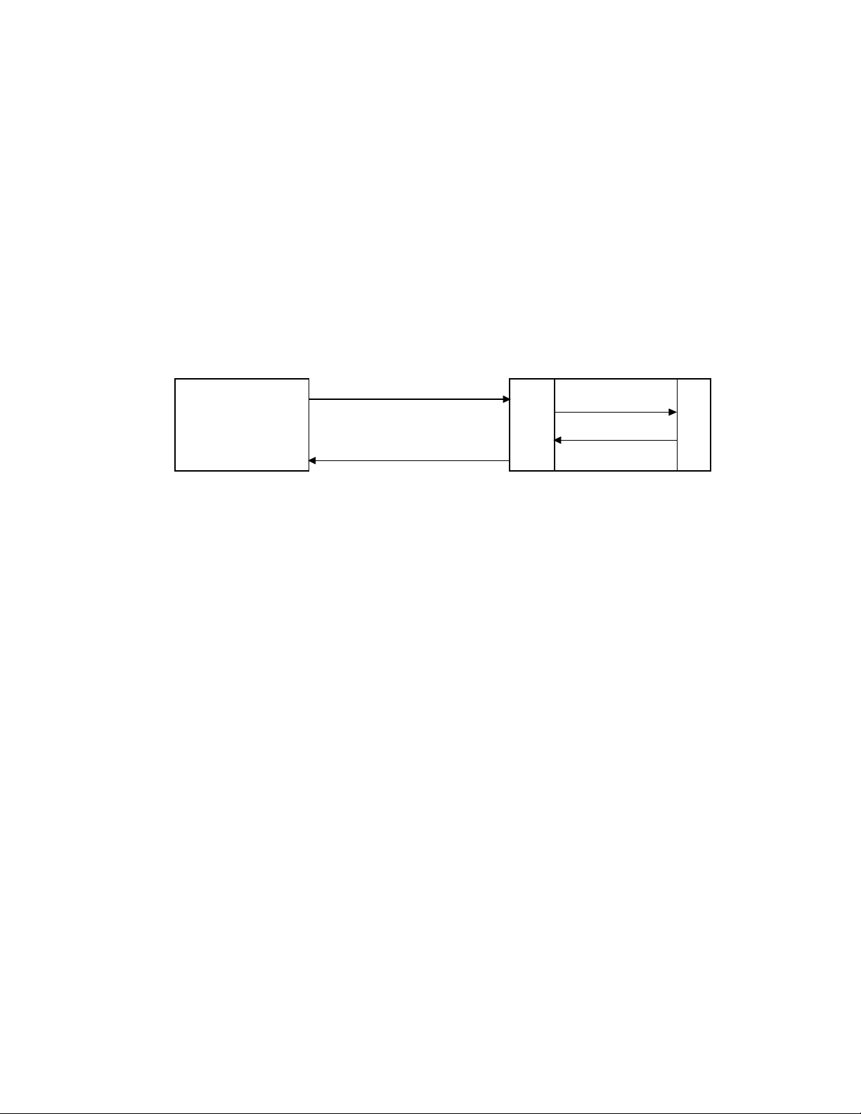
PLC Server Function
The 2572 can function as a server to clients who wish to access the PLC. Figure 5 illustrates the
typical message dialog between the client, the 2572, and the PLC.
1) The client node sends a command message to the 2572 via TCP/IP. For example, the client
may request that the 2572 read and return 25 words of V memory.
1) Command Message
4) Response Message
Client Node
2
2) PLC Command
5
3) PLC Response
7
2
Server PLC / 2572
P
L
C
Figure 5. PLC Server Function
2) Based on the contents of a command message, the 2572 sends commands and data to the
PLC processor via the backplane. For example, the 2572 would issue the applicable
command to the PLC to retrieve 25 words of V memory.
3) The PLC processor responds to the command via the backplane. In the example, the PLC
would return 25 V memory words.
4) After the PLC responds, the 2572 builds the appropriate message and returns it to the client
node. In this example, the 2572 would build a network message containing the 25 words of
data and send it to the client that requested it.
Messages between the 2572 and the client node are encapsulated in the TCP/IP protocol. The client
device must create the TCP/IP packet containing the command and must process responses from the
2572 returned via TCP/IP. The client node may be a suitably programmed computer or another 2572
on the network (see next section). Please reference the CTI 2572 Programming Reference Manual
for details regarding the message interface.
The 2572 will support multiple concurrent client/server sessions. To operate the CTI 2572 as a PLC
server, no PLC logic changes are required. However, you may wish to add PLC logic to set the
network parameters for the module (see page 19, section 2.6. Using PLC Logic to Start the Network
Server).
CTI 2572 Installation and Operation Gui de
5
Page 16
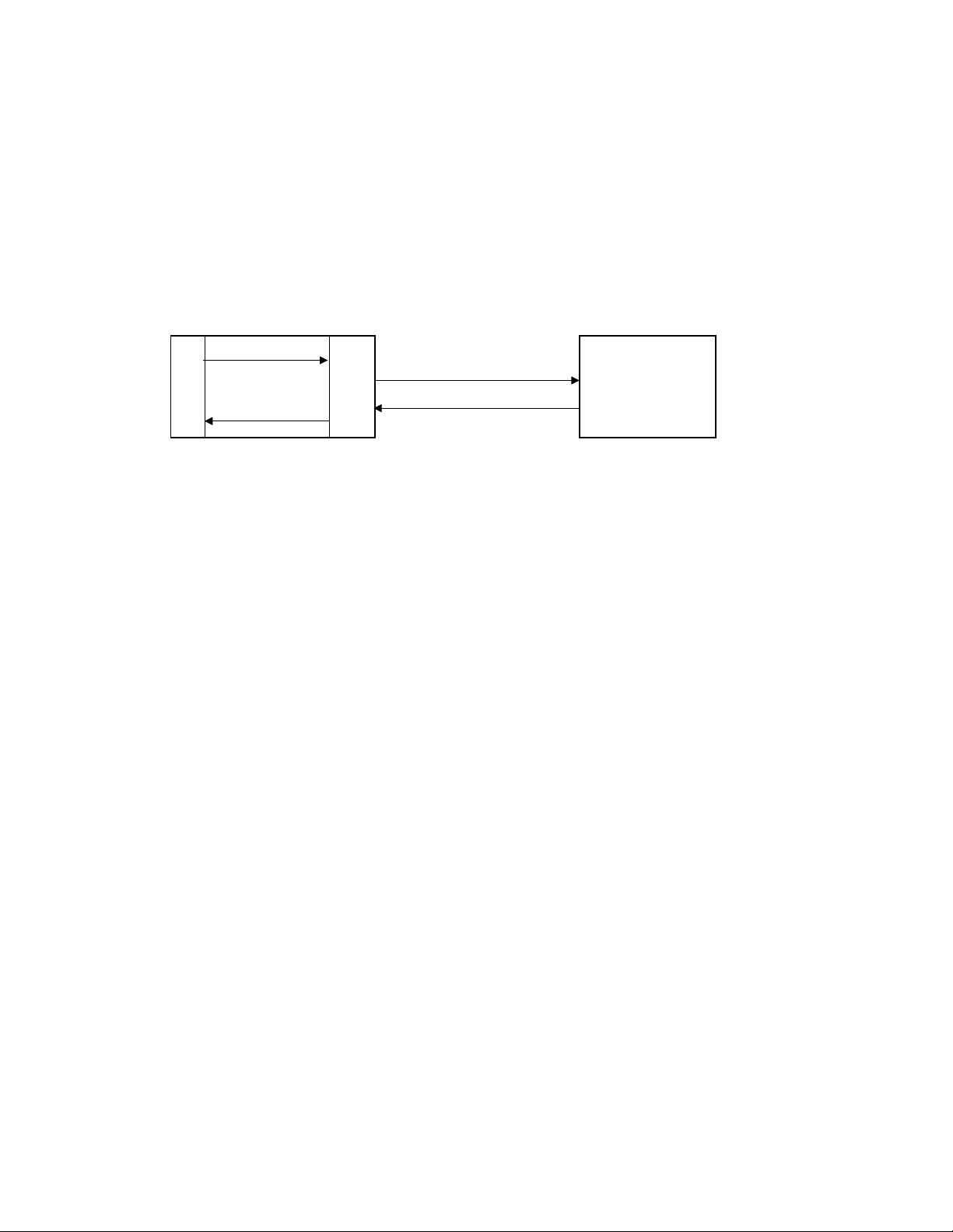
PLC Client Function
The 2572 can also function as a PLC Client. As a PLC Client, the 2572 acts as an agent for the PLC;
it sends messages to other nodes and processes the responses under control of the PLC logic. Data in
the PLC program specifies the recipient and data contents of the message. PLC logic sets a “trigger”
bit to cause the 2572 to send the message.
.
1) 2572 Command
P
L
C
4) 2572 Response
Client PLC / 2572 Server Node
Figure 6. PLC Client Function
In the example above:
1) When the PLC detects a specified event, it sends a command to the local 2572. For example,
the command could be to read 5 words from another node on the network.
2) Based on the command, the 2572 then sends the applicable command via TCP/IP to the
specified network (server) node.
2
5
7
2
2) Command Message
3) Response Message
3) The server node processes the command and returns a response via TCP/IP. In the example,
the server node would return a message containing the specified words.
4) The 2572 processes the network message and notifies the PLC that the operation is complete.
In the example, the 2572 would place the words in a specified PLC memory location and
signal completion of the task.
The 2572 can support multiple concurrent client sessions. The server node shown in the illustration
could be another 2572 or a computer programmed to process the commands and send the appropriate
responses. Information describing the PLC logic required for client operation can be found in
Chapter 3 of this manual.
The 2572 can support multiple server sessions and multiple client sessions concurrently. Therefore,
networked PLCs can use the facilities of the 2572 to participate in multi-session peer-to-peer
communications.
6
CTI 2572 Installation and Operation Gui de
Page 17

1.6. TCP/IP Overview
The CTI 2572 module uses TCP/IP (Transmission Control Protocol/Internet Protocol) to transport
messages between the module and other nodes on the network. TCP/IP is a suite of protocols that
provide routing and delivery services for messages between application programs running on
different processors (called hosts in TCP/IP terminology). You may select between connectionless
(packet based) or connection-oriented (stream based) delivery services.
Connectionless Delivery
Connectionless delivery services allow you to send a message to another node without previously
establishing a logical connection to the other node. TCP/IP provides a format known as the
USER
DATAGRAM PROTOCOL (UDP) for sending and receiving connectionless messages. Connectionless
delivery is simple to implement and consumes a small amount of system resources. However,
delivery of UDP messages is not confirmed by the network protocol. It is left to higher level
protocols to acknowledge receipt of a message. Since the Common ASCII Message Protocol
(CAMP) used with the 2572 will acknowledge receipt of a command message, UDP is the preferred
protocol for most applications, such as process monitoring, which obtain data from the PLC.
Connection-Oriented Delivery
With connection-oriented services, you must first establish a logical connection (known as a virtual
circuit) before network nodes can exchange messages. TCP/IP uses the
PROTOCOL (TCP) to implement connection-oriented services. TCP provides guaranteed delivery and
message flow control. If a message is not delivered correctly, the TCP protocol will automatically
retry. Since TCP is stream oriented, meaning the application program sees a properly sequenced
stream of data rather than individual packets, it is often used for file transfer applications such as
program downloads. You may choose to use TCP for applications, such as data logging, which
require a specific piece of data be delivered in order.
TRANSMISSION CONTROL
Socket Interface
TCP/IP uses a standard structure known as a socket, for the application program interface. The de
facto socket standard is the Berkeley Socket, named for the University of California at Berkeley, who
originally distributed TCP/IP. Originally, the Berkeley Sockets were used with only the Unix
operating system. Today, Microsoft Windows includes TCP/IP support using the Winsock standard, a
derivative of the Berkley Socket standard.
Summary
The TCP/IP protocol is used to send and receive messages via the network. It will function over the
local Ethernet network or over Wide Area Networks. TCP/IP supports both connectionless (UDP)
and connection oriented (TCP) services. UDP is usually sufficient for most applications because the
higher-level application protocol (CAMP) incorporates an acknowledgment to commands. TCP/IP
network software for an IBM compatible personal computer is readily available from a wide range of
sources. For a complete discussion of the TCP/IP protocol, see Internetworking with TCP/IP by
Douglas Comer (1991, Prentice Hall) or other commonly available reference material.
CTI 2572 Installation and Operation Gui de
7
Page 18

1.7. PLC Command Interface
Some 2572 functions require that you use PLC logic to control the operation of the module. The
2572 module provides a standard PLC logic interface for sending messages and processing
responses. The interface consists of two parts:
• Command Blocks - Command Blocks are blocks of contiguous V memory words used to store
module commands and associated parameters. The exact content of the Command Block will
vary with the command being issued.
• Module WX/WY Words - The 2572 module logs in as a Special Function module and is assigned
two WX words and six WY words. PLC logic uses the WY words to select the Command Block
and to trigger the command execution. The status of the module and of command execution can
be monitored via the WX words.
Figure 7 illustrates how the module WX/WY words and the command blocks are used together. The
2572 writes values in the WX words, the PLC writes values in the WY words. WX1 and WY3
contains bits allow the PLC to monitor and control module global status. WY4 and WX2 contain bits
that allow the PLC to trigger commands and monitor command status. The Command Slots (WY5-8)
are used to point to the starting V Memory addresses of the Command Blocks.
To use the module command interface, your PLC logic typically loads a Command Slot with the
address of the desired command block. It then sets a corresponding trigger bit in WY4 to cause the
2572 to execute the command. Your logic then monitors the condition of the command status bits in
WX2 to determine whether the command completed successfully.
MODULE WX/ WY
COMMAND
BLOCKS
WX1
WX2
WY3
WY4
WY5
WY6
WY7
WY8
MODULE STATUS WORD
COMMAND STATUS WORD
MODULE CONTROL WORD
COMMAND CONTROL WORD
COMMAND SLOT 1
COMMAND SLOT 2
COMMAND SLOT 3
COMMAND SLOT 4
Figure 7. 2572 PLC Interface
Please refer to Appendix D for a complete description of the PLC Command Interface.
8
CTI 2572 Installation and Operation Gui de
Page 19

1.8. Getting Started
Assigning an IP Address
Before proceeding you must determine what IP address you will assign to the module. If you are
connecting to an existing network, your network administrator will provide this information. If you
plan on connecting your network to the Internet you should contact the Internet Network Information
Center (NIC) for IP address assignment. If you are installing a stand-alone network, you may choose
any set of IP addresses as long as they adhere to IP addressing conventions. See Appendix E of this
manual for a description of the IP Address numbering conventions.
Choosing and implementing a Module Startup Method
Before the 2572 will accept TCP/IP messages, the module Network Server must be started. You can
use PLC logic to assign the IP address and to start the Network Server or you can have the module
automatically start the Network Server using an IP address stored in the 2572 EEPROM. See
Chapter 2 for a description of these methods. If you choose to use PLC logic, you will need to create
a command block and incorporate a few rungs of ladder into your program. See Section 2.6. Using
PLC Logic to Start the Network Server on page 19.
Setting Module Switches
Module dipswitches configure the serial ports and select the startup method. See Section 2.4. Setting
the 2572 Switches on page 14 for a complete description.
Installing the Module in the PLC I/O Base
The 2572 is a single wide module that installs in a standard SIMATIC 505 PLC rack. For best
performance you should install the 2572 in the first I/O slot of the local base. Chapter 2 describes
unpacking and installation of the module.
Logging the Module in the PLC I/O Configuration
When you initially install the module in the PLC I/O base, you must log the module into the PLC I/O
configuration. The 2572 logs in as 2 WX and 6 WY words. See Checking PLC Login in Chapter 2 on
page 18.
NOTE:
The module will not operate properly until it has been logged in.
Connecting the Module to the Network
You can choose to connect the module directly to 10BaseT cabling or, via a transceiver, to any IEEE
802.3 compliant media. See Section 2.8. Connecting Cables on page 26.
Checking out the Module
You can use both the module indicators and commonly available software to ensure the module is
operating properly. Section 2.9. Module Checkout on page 27, describes these procedure. Chapter 4
also describes the module operation.
CTI 2572 Installation and Operation Gui de
9
Page 20

Using the Module
Assuming you have completed the above steps successfully, the 2572 module is ready for use as a
PLC Server. If you wish to implement PLC Client functions, please refer to Chapter 3 of this
manual.
10
CTI 2572 Installation and Operation Gui de
Page 21

CHAPTER 2. INSTALLATION
The installation of the Model 2572 Ethernet TCP/IP Adapter Module consists of the following steps:
1) Planning the installation,
2) Unpacking and configuring the module,
3) Physical installation,
4) Setting IP information,
5) Connecting cables,
6) Checking the module operation.
2.1. Installation Planning
Ethernet Media
The Model 2572 attaches directly to 10BaseT media (Unshielded Twisted Pair) via the RJ-45
connector. You should select cabling rated CAT 5 or better. Should you choose another Ethernet
medium, you must obtain the appropriate transceiver to attach to the AUI port. Ensure that the cables
you use for Ethernet communications meet the IEEE 802.3 specifications and are appropriate for the
environment in which you are operating.
NOTE:
Check your cabling carefully. Faulty cables and/or connectors are the
leading cause of Ethernet communications problems.
Serial Communications
The serial ports on the 2572 module are provided for configuration and diagnostic purposes. For
typical applications, you can use a standard serial PLC programming cable. Although you may use
the ports to access the PLC, applications or devices that place a heavy transaction load on the module
will degrade network performance. If you have a need to service these devices, consider installing a
separate CTI 2573 module.
Establishing Network Parameters
Before the 2572 can communicate on a TCP/IP network, you must establish the network parameters.
These include an IP Address and Subnet Mask for the module, a TCP/UDP port number for the PLC
Network Server function, and, if your network contains a router, the IP address of the Default Router.
See Appendix E for a complete description of TCP/IP address nomenclature. You may also wish to
refer to general publications describing TCP/IP.
You have a choice of two methods for establishing the network parameters. One method allows you
to use the PLC program to set the IP address and other network parameters. The second method
CTI 2572 Installation and Operation Gui de
11
Page 22

allows you to load the information directly from data stored in EEPROM on the 2572. You will need
to decide which method best suits your requirements.
NOTE:
Unless your application requirements dictate otherwise, CTI recommends that you allow the PLC to
establish the network parameters.
If you choose to establish the network parameters using PLC logic, the 2572 will wait for the PLC to
initiate network startup. Using a special 2572 startup command, the PLC can set the network
parameters. When the module is reset for any reason (for example, during module replacement), the
PLC must restart the server software and re-load the network parameters. The PLC logic to perform
this function is described in Section 2.6 on page 19. Since the IP information is reloaded from the
PLC and is not stored in the module, the IP address remains with the PLC, even if the 2572 modules
are swapped.
If you choose to obtain the network parameters from the EEPROM, the module automatically
initiates network startup based on the values in EEPROM. No PLC logic is required to set the
network parameters. Since the IP address is not associated with the PLC program, you can download
a common program to multiple PLCs using the TCP/IP network. However, if you arbitrarily swap
2572 modules between PLCs, the IP address will move with the module. The effect of inadvertently
swapping IP addresses can cause major problems, since communications directed at one PLC would
actually be going to another PLC.
WARNING:
If you choose to obtain the network parameters from EEPROM, you should ensure your
maintenance procedures safeguard against inadvertent module swaps.
NOTE:
You will need to specify the IP address of the module, the logical port number for the PLC server
function, subnet mask, and the IP address of the default router. You may need to obtain some of this
information from your network administrator before you begin.
2.2. Power Requirements
The Model 2572 requires 6 watts of +5 VDC power, not including any power supplied to a
transceiver connected to the AUI port. If your media configuration requires a transceiver and you
wish to power it from the AUI port, you should include the transceiver power requirement in your
power calculations. The formula for slot power calculation is:
P = 6 + (TP x 1.15)
where P = total power slot requirement in watts and
TP = transceiver power requirement in watts.
IEEE 802.3 specifications allow a transceiver to draw a maximum of 500 ma at 12 VDC from the
AUI port. In practice, many transceivers draw considerably less. Should the total power required
12
CTI 2572 Installation and Operation Gui de
Page 23

exceed the backplane limitation, you may power the AUI from an external 12 VDC power supply.
The 2572 module provides a front panel connector for attaching an external AUI power supply.
NOTE:
The AUI external power circuit contains a reverse protection diode that may induce up to a 0.5 volt
drop. Most transceivers can tolerate this voltage drop. If your transceiver cannot, you should adjust
your external power supply to compensate.
CAUTION:
If you are using a transceiver, make sure that you have included the power requirements for the
transceiver in your calculations. Before inserting the module into the I/O base, ensure that the
PLC power supply capacity is not exceeded.
2.3. Unpacking the Module
Open the shipping carton and remove the special anti-static bag that contains the module.
After discharging any static build-up, remove the module from the static bag. Do not discard the
static bag. Always use this bag for protection against static damage when the module is not inserted
into the I/O base.
CAUTION:
The components on the 2572 module printed circuit card can be damaged by static electricity
discharge. To prevent this damage, the module is shipped in a special anti-static bag. Static
control precautions should be followed when removing the module from the bag and when
handling the printed circuit card during configuration.
CTI 2572 Installation and Operation Gui de
13
Page 24
2.4. Setting the 2572 Switches
Switches on the 2572 are used to select the following:
• AUI Power
• Serial Port Baud Rate
• Hardware Handshaking (RS-232 port)
• DataShare Enable
• Network Startup Option
• EEPROM Write Protect
• Serial Port Protocol
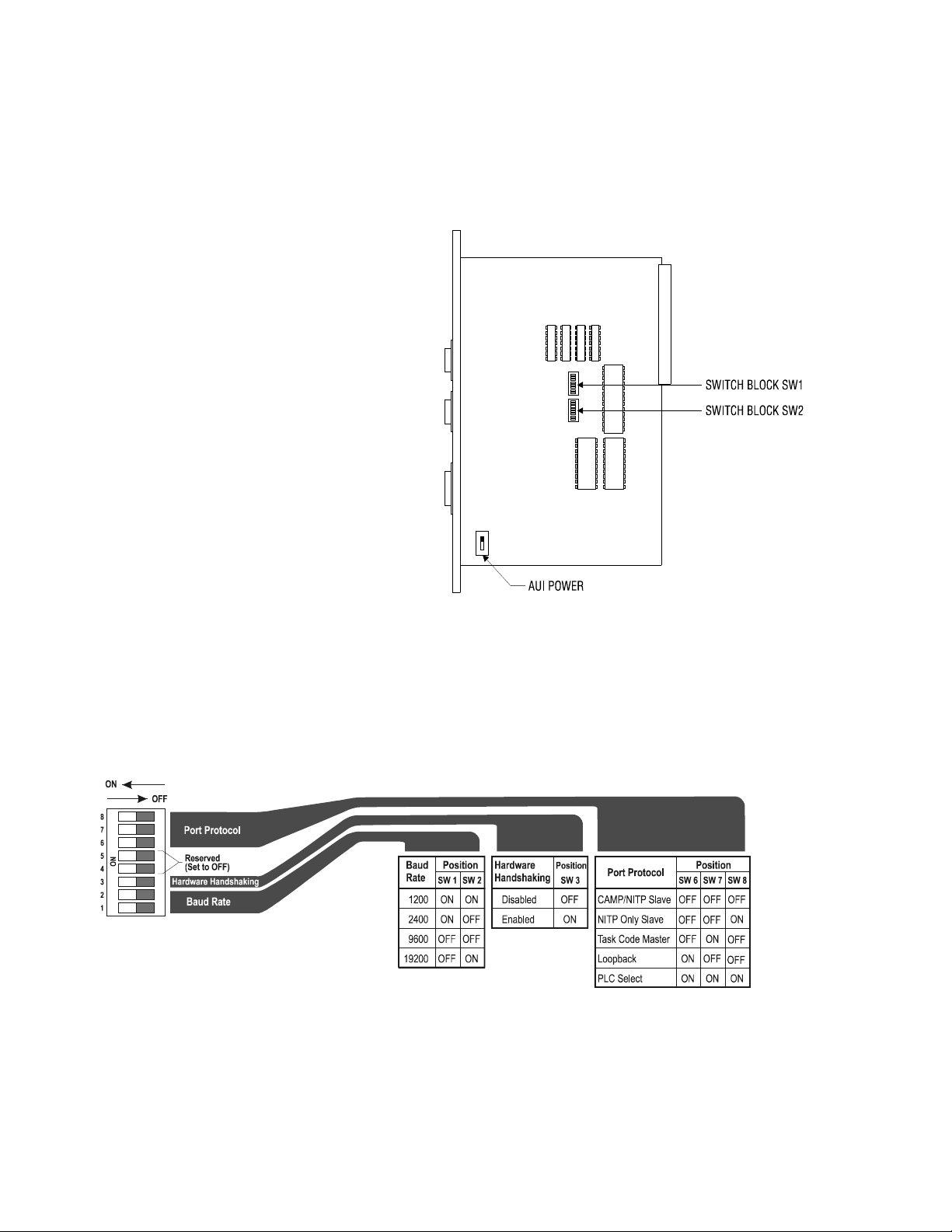
Figure 8 indicates the location of the
switches.
AUI Power Source Switch
The AUI port allows external transceivers to
be attached to the module. The AUI power
source switch is used to select whether
transceiver power is obtained from the PLC
backplane or an external power source. In
most cases, you can set the switch to the
I
NTERNAL position. If you are using a
transceiver that exceeds your backplane
power budget, use the External setting and
provide an external power supply. If you are
not using the AUI port, the position of this switch does not matter.
Figure 8. 2572 Switch Locations
Switchblock 1
Switchblock 1 is used to set the communications parameters for serial port 1.
Figure 9. Switchblock 1
14
CTI 2572 Installation and Operation Gui de
Page 25
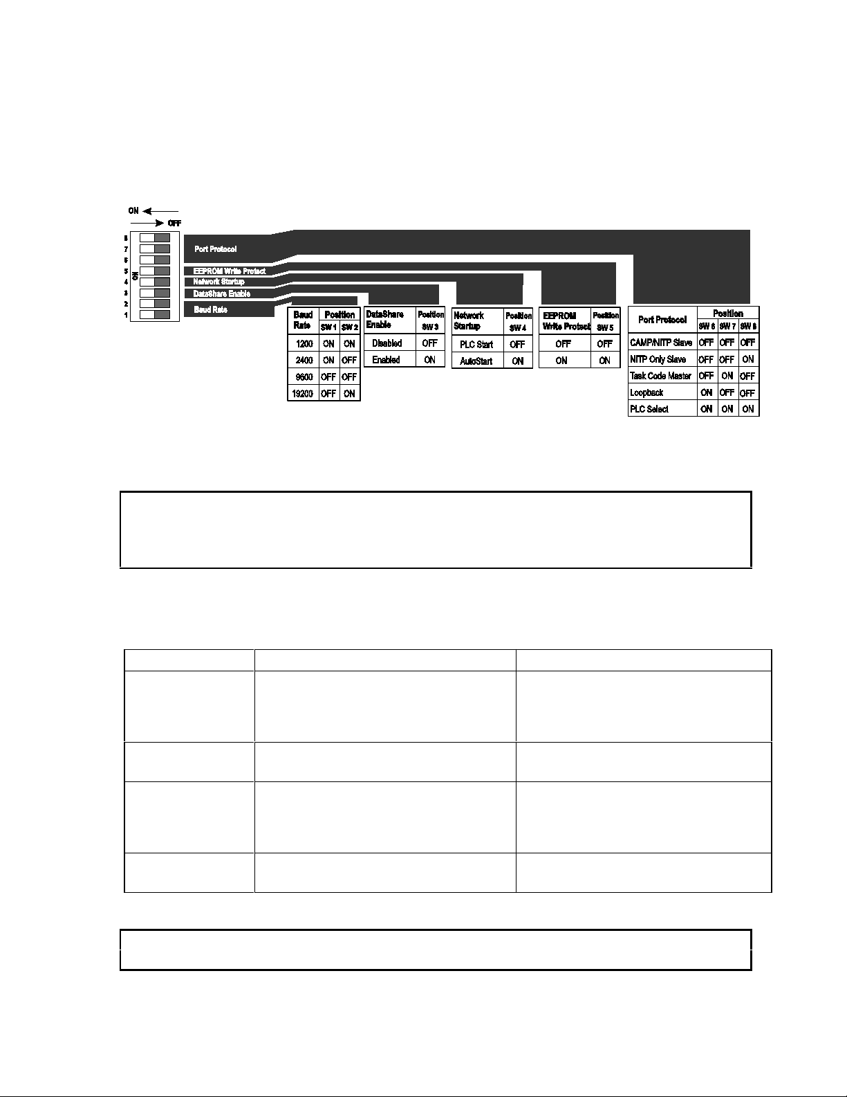
Switchblock 2
Switchblock 2 is used to set the communications parameters for serial port 2. In addition, switches
3,4, and 4 are used to set other module options.
Figure 10. Switchblock 2
NOTE:
The switches on some modules may be labeled OPEN and CLOSED. The Closed position is equivalent
to ON.
Switch settings not shown are reserved and should set to OFF.
Serial Port Protocol
Switches 6, 7, and 8 on each switch block are used to set the protocol used by the port.
Protocol Description Use
CAMP/NITP Supports both CAMP (Common ASCII
Message Protocol) and NITP (NonIntelligent Terminal Protocol).
NITP Only Rejects message formats that are not
strictly NITP compliant.
Loopback Loopback generates a series of ASCII
characters that may be directed back to
the serial port via a loopback connector.
PLC Select Allows the PLC logic to select the port
protocol.
NOTE:
For typical operation, you should set the switches to use the CAMP/NITP protocol.
CTI 2572 Installation and Operation Gui de
CAMP is used to transfer large blocks
of data and to perform module specific
functions. NITP is used by many PLC
programming packages.
Applications which require strict
adherence to the NITP specifications
Testing serial ports and cables.
Used for custom port protocols
15
Page 26

Serial Port Baud Rate
You can individually set the baud rate settings for each serial port. For most applications, a baud rate
of 9600 provides a good balance between performance and reliability.
Port 1 Hardware Handshaking
Hardware handshaking for port 1 can be disabled or to enabled via a switch on Switchblock SW1. If
hardware handshaking is enabled, the attached device must raise CTS before the 2572 will transmit
data. See the diagram below. The switches on some modules may be labeled O
The C
LOSED position is equivalent to ON.
NOTE:
Unless the device you are attaching explicitly requires hardware handshaking, you should leave
PEN and CLOSED.
hardware handshaking disabled.
DataShare
Switch 3 on Switchblock 2 (SW2) enables the DataShare Protocol. When this is enabled, other
protocol functions are significantly restricted. See CHAPTER 6. DATASHARE P.
Network Startup Options
Switch 4 on Switchblock SW2 allows you to select how the 2572 starts up the PLC Network Server
function. If you set the switch to PLC S
Network Server command (see Section 2.6, page 19). The command block for this command
contains the network parameters (including IP address).
If you set the switch to the AUTOSTART position, then the 2572 will automatically start the Network
Server function, obtaining the network data from EEPROM on the 2572. The switches on some
modules may be labeled O
Before you can use the AUTOSTART option you must store your network data in EEPROM. You can
PEN and CLOSED. The CLOSED position is equivalent to ON.
use either PLC logic or a serially attached PC with a CTI supplied program to write the EEPROM.
The data will remain stored in EEPROM until changed. See page 25 for information on writing
EEPROM. The IP address stored in the EEPROM has purposely been set to an invalid IP address at
the factory.
Unless you have a significant reason to do otherwise, you should set the switch to PLC START and
use PLC logic to start the Network Server. Then, if you swap out a module, the PLC will
automatically load the new module with the correct IP address information and other network
parameters. If you choose the A
UTOSTART option, your maintenance procedures should guard
against inadvertent module swaps, since the IP address will move with the module.
TART, then the 2572 will wait for the PLC to issue a Start
16
CTI 2572 Installation and Operation Gui de
Page 27

EEPROM Write Protect
Switch 5 on switchblock SW2 protects the data in the EEPROM from being overwritten. When
W
RITE PROTECT is on, the network parameters stored in the EEPROM cannot be changed by the PLC
program or by a PC attached to a serial port. If a program attempts to write to the EEPROM when
the W
RITE PROTECT switch is on, the 2572 will return an error code.
See Section 2.6 on page 19 for procedures used to start the PLC network server using PLC logic. See
Section 2.7 on page 120 and Section 2.8 on page 25 for information on reading and writing the
module EEPROM.
NOTE:
Switchblock switch positions are read only at module startup.
The 2572 module is shipped with all DIP switches in the OFF (OPEN) position. This corresponds to:
Baud Rate ....... ..........................9600
Hardware Handshaking..............DISABLED
Serial Port Protocol.....................CAMP/NITP
Network Startup Mode................PLC START
EEPROM Write Protect..............PROTECT OFF
DataShare ....... ..........................DISABLED
2.5. Physical Installation
Inserting the Module into the I/O Base
Hold the top and bottom of the bezel and slide the module carefully into the slot, pushing it all the
way into the base. If you have inserted the module correctly, you will feel a slight increase in
resistance as the module mates with the base backplane connector. Once the module is fully seated
in the slot, tighten the captive screws at the top and bottom to hold the module in place. To remove
the module from the I/O base, loosen the captive screws, then remove the module. Take care not to
damage the connector at the back of the module when inserting or removing the module.
Power Up
Turn on the base power supply. Once the 2572 diagnostics have completed and the network
parameters are set, the ACTIVE indicator should illuminate. If the indicator does not illuminate or
exhibits a blinking pattern, see Chapter 5 of this manual for troubleshooting information.
CTI 2572 Installation and Operation Gui de
17
Page 28

Checking PLC Login
Next, log the module into the PLC I/O configuration. The 2572 logs in as a special function module
with 2 WX and 6 WY words. To configure the PLC I/O refer to your PLC programming software
manual. In the example below, the 2572 module is installed into slot 1 on I/O base 0 and will be
logged in starting at address 1. Your configuration may differ.
I/O MODULE DEFINITION FOR CHANNEL . . . 1 BASE . . . . . . .
00
I/O NUMBER OF BIT AND WORD I/O SPECIAL
SLOT ADDRESS X Y WX WY FUNCTION
01 00001 00 00 02 06 YES
02 00000 00 00 00 00 NO
.. ...... .. .. .. .. ...
15 00000 00 00 00 00 NO
16 00000 00 00 00 00 NO
Figure 11. Sample I/O Configuration
After you read the I/O base, if the number of WX and WY words are the same as those shown in the
example above and Special function = YES, then the PLC can recognize the module. Change the
address as required by your application and save the result. If the line is blank or erroneous, re-check
the module to ensure that it is firmly seated in the I/O base slot. Generate the PLC I/O configuration
chart again by reading the I/O base. If the problem persists, contact your distributor or contact CTI.
NOTE:
If you do not log the module in correctly, it will not function properly.
18
CTI 2572 Installation and Operation Gui de
Page 29

2.6. Using PLC Logic to Start the Network Server
The Start Network Server command is used when you want to establish the network parameters using
PLC logic. When you use PLC logic to set the network parameters, you can ensure that the IP
address is directly associated with the PLC and not the module.
NOTE:
Before you can use PLC logic to start up the PLC network server function, the Network Startup
Option switch must be set to PLC Start (See Figure 10. Switchblock 2 on page 15).
The 2572 uses the PLC V memory to store command information and the module WX/WY words to
control execution of the commands. If you are not familiar with this interface, please refer to
Appendix D of this manual. Also see the ladder logic example on page 24.
NOTE:
If you store the network parameters in EEPROM and use the module AUTOSTART switch option, you
are not required to execute this command.
The network data parameters are set by the PLC when the Start Network Server command block is
executed. This block is shown on the following page. In the illustration, a bold entry is a required
value. A non-bold entry is a recommended value that you should use unless you have reason to do
otherwise. Values for the command block entries are shown in both hexadecimal and decimal
(integer) format. Using your PLC programming software, you can configure a chart to display the
values either way.
This command should be executed only when the Network Configuration Required bit (NET CFG) is
set. The N
reset for any reason. It remains on until the network parameters have been set. If you have chosen
the PLC Start option for network startup, you must successfully complete this command before the
2572 will respond to any other network commands. See the ladder example on page 24.
When you trigger the Start Network Server command, if the command block contains invalid data,
the 2572 will return an error code and then halt. To recover, you must correct the command block
ET CFG bit is set shortly after power is first applied to the module or after the module is
NOTE:
entry and reset the module by cycling power.
CTI 2572 Installation and Operation Gui de
19
Page 30

Start Network Server Command Block
Offset Description Hex
Value
0 Command Error Word
1 Command (Start Network Server)
2 Connection Number (19291 - 19299) 4B62 19298
3 Protocol Manager Number
4
5 TCP Keep Alive Interval in Seconds (0=default = 60)
6 IP Address of this Module (High 16 bits)
7 IP Address of this Module (Low 16 bits)
8 TCP / UDP Port Number 05E1 1505
9 IP Address of Default Router (High 16 bits)
10 IP Address of Default Router (Low 16 bits)
11 Max Number of TCP Connections (0=default) 0000 0
12 Subnet Mask (High 16 bits)
13 Subnet Mask (Low 16 bits)
14 Unused - reserved for future use (Set to 0)
15 Unused - reserved for future use (Set to 0)
Startup Option Bits (see description below) 0000
(Set to 65000 or greater to disable Keep Alive)
0000 0
0004 4
0023 35
0000 0
0000 0
0000 0
Offset 0 Error Word - Set to 0 so that any previous error code is cleared.
Decimal
Value
0
Offset 1 Command Code - The Command for Start Network Server is 4.
Offset 2 Connection Number - You should set this to number in the range of 19291 to 19299
to prevent inadvertent conflict with any client connections you may create. The
value of 19298 is used in CTI examples.
Offset 3 Protocol Manager Number - Protocol Managers control the operation of the serial
and network ports. Protocol Manager 35 (23 hex) selects the PLC Network Server.
Offset 4 Startup Option Bits - These bits allow you to configure certain options for the PLC
server. The bits are used as follows:
Bit 1 Bit 2 Bit 3 Bits 4-16
TCP Server Disable
0 = TCP Enabled
1 = TCP Disabled
20
UDP Server Disable
0 = UDP Enabled
1 = UDP Disabled
Echo Server Disable
0 = Server Enabled
1 = Server Disabled
CTI 2572 Installation and Operation Gui de
Reserved
(set to 0)
Page 31

ERVER DISABLE - Setting this bit to 1 will disable TCP connections to the PLC
TCP S
server. The 2572 will reject attempts by a remote client to connect via TCP to the
server. However, you can still initiate a client TCP connection from this PLC. A
setting of 0 (TCP Enabled) is the normal mode.
UDP S
ERVER DISABLE - Setting this bit to 1 will disable UDP (connectionless)
protocol for the server. The 2572 will reject all UDP datagrams sent to the server.
However, you can still initiate a client UDP connection from this PLC. A setting of
0 (UDP Enabled) is the normal mode.
E
CHO SERVER DISABLE - Setting this bit to 1 will disable the TCP and UDP echo
servers (Port 7). TCP connection attempts and UDP datagrams directed to port 7
will be rejected by the 2572. A setting of 0 (Echo Server Enabled) is the normal
mode.
You might choose to disable TCP for the server if you need additional process slots
for creating client network connections. Disabling TCP frees two process slots
which allows you to create two additional network connections. When you disable
TCP, the server will still process UDP messages.
You might choose to disable UPD if you want to support only connection-oriented
conversations. This option can provide a means to limit the transaction load on the
PLC server, since you can also control the number of TCP connections allowed (see
offset 11). You may also choose to disable UDP if you need an additional process
slot for a TCP/IP socket. When you disable UDP, the 2572 is able to support one
additional TCP server connection or PLC Client network connection.
You might choose to disable both TCP and UDP if you are using the 2572 in client
mode only. Note that you must have at least one enabled 2572 server or computer
host server somewhere on the network to respond to your messages. This option
frees up three additional process slots.
The Echo Servers (TCP and UDP) provide a handy diagnostic tool for checking out
TCP/IP communications at a level higher than Ping. You may wish to disable the
Echo Servers if you need to obtain more process slots for the 2572 PLC server.
Disabling the Echo servers frees up two process slots.
Unless you have a specific reason to do otherwise, use the defaults.
NOTE:
You cannot disable TCP, UDP, and the ECHO servers simultaneously. At least one must be enabled
in order to start the network server.
Offset 5 TCP Keep Alive Interval - This value specifies the amount of elapsed time (in
seconds) without any messages from the client application before the 2572 will
automatically close a server TCP socket. If the value is set to 0, then the 2572 will
use the default value of 60 seconds. To disable Keep Alive, set the value to 65,000
or greater.
CTI 2572 Installation and Operation Gui de
21
Page 32

Offset 6-7 IP Address Offset 6 should contain the high 16 bits of the module IP address. Offset
7 should contain the low 16 bits of the IP address. An IP address of 0.0.0.0 (0000
0000 hex) or greater than 223.255.255.255 (DFFF FFFF hex) is will return an error.
Offset 8 TCP/UDP Port - This will be the port number used to connect to the 2572 PLC
Server application. The examples in this manual assume that this will be set to 1505
decimal. You should use this value unless you have a reason to do otherwise. A port
number of 0 is invalid.
Offset 9-10 IP Address of Default Router - This identifies the address of the router to which
unknown IP addresses will be directed. Offset 8 contains the high 16 bits of the
address and Offset 9 contains the low 16 bits. An address greater than
223.255.255.255 (DFFF FFFF hex) will return an error. If you do not have a router
on your network, set this to 0.0.0.0 (0000 0000 hex).
Offset 11 Maximum Number of TCP Connections- This specifies the maximum number of
concurrent TCP connections to the PLC server that will be allowed. Once the
maximum number has been attained, the 2572 will reject further attempts to connect
until a connection is relinquished. Once a connection is properly closed, the slot is
available for another connection. If you set the value in this word to 0, then the 2572
will use the default module value (8). You may set this to a number less than 8 to
limit access. You may also increase the number beyond 8 as follows:
• Increase the number by 1 for each unused Client connection (Up to 8),
• Increase by 2 if you disable the Echo Servers (see offset 4),
• Increase by 1 if you disable UPD Server (see offset 4).
Offset 12-13 Subnet Mask - Specifies the subnet mask assigned to this network. Offset 12 contains
the high 16 bits of the mask and Offset 13 contains the low 16 bits. If offset 12 and
13 contain a value of 0, then the subnet mask will default to the standard for the IP
address class. A subnet mask must contain all 1’s in the network portion of the IP
address and must allow at least 2 bits of host address. In addition, the subnet mask
cannot be set so that the derived host address is 0 or a broadcast address (all bits set
to 1). See Appendix D.
NOTE:
All computers on a physical network must use the same Subnet mask and
Network ID; otherwise, addressing and routing problems can occur. Host ID’s on the same network
must be unique.
22
CTI 2572 Installation and Operation Gui de
Page 33

NOTE:
If you set the startup option to PLC START, you must successfully complete this command before any
other network functions will execute. If you set the startup option to AUTOSTART and the EEPROM
contains valid network parameters, you are not required to execute this command.
NOTE:
You must set the module startup option to AUTOSTART and reset the module before any EEPROM
changes will take effect.
When you are setting up the various IP addresses and subnet mask, you should set up your PLC
programming software to display the words in hexadecimal. Then you can enter each byte of the
dotted notation individually. For example, if the IP address were 198.35.34.10, you could enter the
first word as hex C623 where the high byte (C6) is the hex equivalent of decimal 198 and the low
byte (23) is the hex equivalent of decimal 35. Similarly, you would enter the second word as hex
220A. See the following illustration.
Hex Value
Dotted Decimal
Hex Value
C6 23
198. 35.34.10
22 0A
C623
220A
Figure 12. Representing IP Address in Hexadecimal Format
Offset 6
Offset 7
CTI 2572 Installation and Operation Gui de
23
Page 34

Ladder Logic Example
The following diagram illustrates the ladder logic that executes the Start Network Server command
block. This example assumes that the command block is located in V memory starting at V500 and
that command slot 1 is used for the command. See the CTI 2572 PLC Command Interface Reference
Manual for details.
C100
WX1.3
WY4.3
LDC
WY5
500
C100
WX2.3
C100
Set the command to
Coupled Mode
WY4.2
Sets the Command
Trigger
WY4.3
Figure 13. PLC Logic Example
Rung 1 loads the location of the Command Block (V500) into Command Slot 1 (WY5). Once the
control relay is on, it seals off the command. The load command will be bypassed on subsequent
scans.
Rung 2 sets the C
(WX1.3) is on and the C
C
OMMAND BUSY (WX2.3), it lowers the COMMAND MODE (WX4.2) and COMMAND TRIGGER
OMMAND TRIGGER (WY4.3) and COMMAND MODE (WY4.2) when the NET CFG bit
OMMAND BUSY bit (WX2.3) is off. When the logic sees the 2572 raise
(WX4.3), completing the coupled mode cycle.
The N
ET CFG bit will be raised by the 2572 at any time the network configuration parameters are not
set. Therefore this logic will re-execute the Start Network Server command, if the 2572 is reset for
any reason.
NOTE:
Do not use retentive relays in this logic. Proper operation of this logic depends on the control relay
transitioning from off to on when power is cycled.
24
CTI 2572 Installation and Operation Gui de
Page 35

2.7. Automatically Starting the Network Server
Storing Network Parameters in EEPROM (PC Method)
Before you can automatically start the Network Server, the network parameters, including the module
IP address, must be stored in EEPROM on the 2572. You can accomplish this task using an IBM
compatible PC and a utility program from CTI.
1) Attach the PC to Port 1 (RS-232) using a serial cable wired for RS-232. See Appendix A for
a typical cable example. The cable that you use with your PLC programming software
should work properly.
NOTE:
Make sure that the communications parameters set for the 2572 match those of the PC and that the
CAMP/NITP protocol is selected (see section 2.4 on page 14).
2) Place the diskette labeled CTI 2572 Utilities in a 3.5" diskette drive.
3) Run the IPSET program from the diskette.
4) Follow the instructions on the screen for establishing the network parameters.
NOTE:
Ensure that the EEPROM Write protect switch is off (See Figure 10. Switchblock 2 on page 15.)
You can also use the IPSET program to read the network parameters contained in the EEPROM.
Complete instructions for using the IPSET program can be found in the IPSET.TXT file located on
the 2572 Utilities diskette.
Selecting the AUTOSTART Startup Method
Once you have completed setting the IP address, you should power down the module and ensure that
Network Startup Option Switch is set to A
Protect switch to O
If you do not set the Network Startup Option switch to the AUTOSTART position and there is no PLC
N. The new IP address will take effect when power is re-applied to the module.
logic to set the network parameters, the IP address will not be set. (The module ACTIVE LED will
CTI 2572 Installation and Operation Gui de
UTOSTART. You may also wish to set the EEPROM Write
NOTE:
continue to blink).
25
Page 36

2.8. Connecting Cables
Connecting to the 10BaseT Port
Insert the 8 pin (RJ-45) plug on your unshielded
twisted pair cable into the RJ-45 jack on the
2572. Push the plug into the jack until the plug
clicks into place. Attach the other end of the
cable to a hub.
When a link beat is detected on the 10BaseT
port, the 2572 automatically selects this port.
When you attach a cable that is connected to an
Figure 14. 10BaseT Connection
active hub, the Link Beat (LB) LED should light.
Connecting to the AUI Port
The AUI port is equipped with a standard locking connector. To
attach a transceiver or AUI cable to the AUI connector:
1) Slide the AUI retaining ring to the full down position.
2) Plug the transceiver or cable into the 2572 AUI port.
3) Using the blade of a small screwdriver, slide the AUI
retaining ring to the full up position.
4) Ensure that the transceiver or cable has been locked in
place.
5) Attach the network cable to the transceiver.
The clearance between some transceivers and the front panel of
the 2572 can make it difficult to slide the retaining ring to the
locked position. In this case you may wish to connect the cable
or transceiver with the module removed from the backplane.
With the module removed, the retaining ring can be accessed
Figure 15. AUI Connection
from the rear of the front panel.
NOTE:
The AUI POWER switch must be set to INTERNAL to obtain power for the transceiver from the PLC
power supply. See page Figure 8. 2572 Switch Locations on page14.
26
CTI 2572 Installation and Operation Gui de
Page 37

Connecting to the Serial Ports
Port 1 provides a subset of the RS-232C electrical interface. Cables for the RS-232 ports should be
no longer than 50 feet. Port 2 provides an RS-422 electrical interface. RS-422 cables may be up to
4000 feet in length.
The serial port connectors on the 2572 have been designed to accept commonly used serial cables.
The pin-outs on the RS-232 port and the RS-422 port match those found on the SIMATIC TI 545
PLC. Should you choose to construct your own custom cables, please refer to Appendix A for
connector pin-out descriptions.
2.9. Module Checkout
Power On
When power is applied to the 2572, the ACTIVE LED should light after about one or two seconds.
If the ACTIVE LED fails to light and you are certain that power is applied, then the module
hardware is defective. If the ACTIVE LED periodically cycles off and on every two seconds, it
indicates that the module diagnostics have detected a hardware problem. Refer to Chapter 5
Troubleshooting before proceeding.
If the LED blinks rapidly (about once per second), it indicates that the network parameters (including
IP address) for the module are not set. Refer to Section 2.6 on page 19 and Section 2.7 on page 120
for information on setting the parameters.
NOTE:
If you chose to obtain the IP address information from the PLC, the PLC switch must be set to the
RUN position before the program can transfer the information to the 2572.
Ethernet (10BaseT Connector)
When you attach to the network using the 10BaseT connector the following should occur:
1) The AUI LED should extinguish and the LB (Link Beat) LED should illuminate. This
indicates that a valid link beat is being obtained from the hub and that the 10BaseT port has
been selected by the 2572.
2) If you are attached to an active network, you should see the Ethernet RCV (receive) LED
flicker, indicating network signals are being received.
If the above conditions are not met, refer to Chapter 5.
CTI 2572 Installation and Operation Gui de
27
Page 38

Ethernet (AUI Connector)
When you are using an Ethernet transceiver attached to the AUI port you should experience the
following:
1) The AUI LED should light and the LB LED should not be lit. This indicates that the AUI
port has been selected by the 2572.
2) If you are attached to an active network, you should see the Ethernet RCV (receive) LED
flicker, indicating network signals are being received.
If the above conditions are not met, refer to Chapter 5 of this manual.
NOTE:
If you are connected to both the AUI port and the 10BaseT port, the 2572 will automatically select
the 10BaseT port if a Link Beat is received on the port. If no Link Beat signal is received on the
10BaseT port, the 2572 will automatically select the AUI port.
TCP/IP
If functioning properly, the 2572 will respond to an ICMP Echo Request message known as a ping.
When you ping the 2572 from a network node, it should reply. If the module does not reply, make
sure that you have set the module IP address properly. When converting from dotted decimal format
to dotted hexadecimal format, it is easy to make a mistake.
Serial Ports
If you wish to check out the serial ports, you should attach an operator interface device which
supports NITP (such as a CTI 5250 series access module) to one of the serial ports. Then send a
command to the 2572 (such as a Read V Memory).
You should observe the following:
1) The RCV (receive) LED for the port should blink when the command is sent,
2) Within a second (approximately), the XMT (transmit) LED for the port should blink,
indicating a response has been sent from the 2572.
3) The attached device should display the appropriate response.
28
CTI 2572 Installation and Operation Gui de
Page 39

CHAPTER 3. MODULE OPERATION
3.1. General Module Operation
When the 2572 is powered on, it performs a Power On Self Test (POST) to determine if all module
components are operating properly. The test takes only a few seconds. Once the POST is complete,
the ACTIVE LED should blink at a fast (2Hz) rate, indicating that the network parameters have not
been loaded. Once the network parameters are successfully loaded, the ACTIVE indicator will be
illuminated (on steady). If the ACTIVE LED is not lit or if it is blinking, please refer to Chapter 5
for troubleshooting information.
3.2. Ethernet TCP/IP Operation
When the 2572 module is connected to a network that is generating Ethernet traffic, the Ethernet
RCV LED should blink. This indicates that the Ethernet receiver on the 2572 senses the carrier
signal.
NOTE:
A blinking Ethernet RCV LED does not indicate that valid frames are being received or that frames
are addressed to this 2572. It merely indicates the presence of a physical signal. When very short
frames are received, the LED blink may not be noticeable. The LED blinks relate to general activity;
they cannot be used to count individual frames.
When the 2572 is transmitting Ethernet frames, the Ethernet XMT LED should blink.
NOTE:
The Ethernet XMT LED may blink periodically, even though no command requiring a response has
been sent to the module. This activity is the result of TCP/IP activity such as an ARP (Address
Resolution Protocol) or other ICMP message.
If you are using the 10BaseT connector, the LINK BEAT (LB) LED should be lit, indicating that the
2572 is receiving a Link Beat signal from the hub. If you are using the AUI port, the AUI LED
should be lit, indicating that the 2572 module has selected the AUI port.
The COL (Collision) LED may flash occasionally, indicating that the 2572 detected a collision on the
Ethernet network; light activity is normal. If the LED flash activity is frequent, your network cabling
could improperly terminated or you may be experiencing excessive network traffic.
The POL (Reversed Polarity) LED should not be lit. This indicates that the cable has been
improperly wired. Although the 2572 circuitry will correct for this condition, you should repair or
replace the cable.
CTI 2572 Installation and Operation Gui de
29
Page 40

3.3. Serial Port Operation
The 2572 serial ports provide a method for configuring the module, performing diagnostic
operations, and accessing the PLC memory. The 2572 module has a Transmit LED and a Receive
LED for each port. When a signal is received at the port, the Receive LED will light. When a signal
is transmitted from the port, the Transmit LED will light. When the port is in use, the LED’s should
appear to flicker.
NOTE:
The serial ports compete with the network port for access to the PLC and module resources. Heavy
use of the serial ports will slow down network access. To maximize network performance, avoid
using the serial ports for sustained PLC monitoring activity. Instead, consider installing a CTI 2573
module to attach the operator interface devices.
3.4. Serial Redirect Operation
The Serial Redirect function allows you to redirect PLC commands arriving at a 2572 serial port to
another PLC located on the network. Using this feature you can use most PLC programming
programs and operator interfaces (such as the CTI 5251) to perform remote programming and data
access.
To redirect the serial port, you must execute a program named IPRDIR.EXE. This program is
located on the 2572 Utilities diskette included with your module. The diskette also contains a text
file IPRDIR.TXT that describes the use of the program in complete detail.
You may run IPRDIR from the command line or from a batch file. Once the program has been
successfully executed, the NITP commands from the operator interface device or the PC program
will be directed to the remote unit. All responses from the remote unit will be returned via the serial
port.
CAUTION
Exercise care in redirecting the serial port. Make sure that you know which PLC you are
communicating with. If you are using a DOS PC program such as TISOFT, it is best to use a
batch file to:
1. Run IPRDIR to set the redirection,
2. Run the DOS program,
3. Run IPRDIR to reset the serial port to local.
NOTE:
When the module is reset, all serial ports are always reset to Local operation. Any Serial Redirect
settings will be canceled.
30
CTI 2572 Installation and Operation Gui de
Page 41

CHAPTER 4. CAMP CLIENT COMMANDS
4.1. Overview
The CAMP client commands are used when you wish to use PLC logic to initiate communications.
This function may be used for peer to peer communications among PLCs or to send unsolicited data
to your HMI application. For example, you might use this function to report alarms to a supervisory
PC, avoiding the requirement to continuously poll for alarm data.
NOTE:
If you are using the 2572 in Server mode only, you can skip the remainder of this section.
4.2. Create Socket Command
The CREATE SOCKET command provides a means for your PLC logic to refer to another network
node when sending messages. You must complete the C
send messages to another node on the network.
REATE SOCKET command before you can
The C
REATE SOCKET command creates a local TCP/IP socket and associates it with the remote
socket specified by the values for IP address and port in the command block. If TCP is specified, an
actual logical connection to the remote node is attempted. If the connection cannot be established, the
2572 will return an error code to the PLC. If UDP is specified, the 2572 module saves the address
and port number as the default remote socket, but no connection attempt is made. Once the C
REATE
SOCKET command completes successfully, your logic can use the Connection Number to refer to the
remote socket. You can establish up to eight concurrent connections.
Create Socket Command Block
Offset Description Hex Decimal
0 Error Word
1 Command Code (Create Socket)
2 Connection Number (19221 - 19228)
3 Protocol Manager Number
4 Startup Option Bits (see description below) 0000 0
5 Type of Service (1 = TCP, 2 = UDP)
6 IP Address of Remote Device- High 16 bits
7 IP Address of Remote Device - Low 16 bits
8 Unused (Set to 0)
9 Remote Device - TCP/UDP Port Number
10-15 Unused (Set to 0)
CTI 2572 Installation and Operation Gui de
0000 0
0003 03
0024 36
0000 0
0000 0
31
Page 42

Offset 0 Error Word - Set to 0 so that any previous error codes are cleared.
Offset 1 Command Code - The Command Code of the C
REATE SOCKET command is 03.
Offset 2 Connection Number - Network Client connection numbers may range from 19221
through 19228. Any connection number within the valid range can be assigned, as
long as the number is unique. Connections can be closed and re-used, if desired. To
help keep track of the connection numbers, you may wish to assign connection
numbers sequentially.
Offset 3 Protocol Manager Number - Protocol Managers control the operation of the serial
and network ports. The Protocol Manager Number for the CAMP Client protocol
manager is decimal 36 (hex 24).
Offset 4 Startup Option Bits - (firmware version 5.0 or greater).
Bits 1 - 14 Bit 15 - IP Address Location Bit 16 - Client Priority
Not Used 0 = Use IP Address in CREATE
SOCKET Command Block.
1 = Use IP Address in M
TRANSFER Command Block
(UDP Only)
EMORY
0 = Normal Priority
1 = High priority
When bit 15 is set to 1 (Offset 4 = 0x0002) and the UDP protocol is selected (in
Offset 5), the Command Blocks used for Memory Transfer (R
EAD REMOTE, WRITE
REMOTE, and MEMORY EXCHANGE) will specify the IP Address and Port Number for
the remote device (See Section
4.4. Memory Transfer Commands.)
This feature allows you to use a single socket to communicate with different remote
devices. When bit 15 is set to 0, the IP address and port number entered in this
C
REATE SOCKET command block will be used. The TCP protocol, since it is
connection-oriented, will always use the IP address and port number in this C
REATE
SOCKET command block. If you select TCP and set bit 15 to 1, the 2572 will return
an error.
NOTE:
Even if you set bit 15 to 1, you still must provide a valid IP address and Port number in the
Command Block of the CREATE SOCKET command. If you don’t do this, a Command Error will be
generated when you execute the CREATE SOCKET command.
32
CTI 2572 Installation and Operation Gui de
Page 43

Bit 16 controls the priority given to this client application. When bit 16 is set to 0
(offset 4 = 0x0000), the client application will execute with a normal priority. When
bit 16 is set to 1 (offset 4 = 0x0001), the client application will execute with a high
priority. High priority client applications will be scheduled before all server
applications and all client applications operating at normal priority. One use of the
high priority setting could be sending critical alarm data. You should use normal
priority unless your application definitely requires high priority.
NOTE:
Use the high priority setting with care. You can significantly degrade the 2572 network server
performance by setting several client applications to high priority then continuously triggering data
transfer commands for the client applications.
Offset 5 Type of Service - Selects between UDP (connectionless) or TCP (connection-
oriented) service. Using UDP, the local socket is created but no connection is
established with the target node. Using TCP, a virtual circuit connection is
established with the other node. If the TCP connection cannot be established, the
2572 will indicate an error.
NOTE:
If TCP is selected and the connection with the target node (remote host) is lost, the 2572 will report
a socket connection error code (such as 240A - Socket not Connected) the next time you attempt to
read/write data. The connection may be lost due to problem with the remote host or the network.
After the error is acknowledged, the 2572 will complete error recovery by automatically closing the
socket. A subsequent attempt to read/write data will result in a 00A6 (connection not active) error.
See Appendix B for error code listings. Your logic should re-execute the Create Socket command if
the connection is not active.
Offset 6-7 IP Address - If the IP ADDRESS SELECTION option bit in Offset 4 is set to 0, these
words specify the IP address of the destination node. Since the IP address consists of
32 bits, the address is contained in two 16 bit words. An IP address of 0.0.0.0 (0000
0000 hex) or greater than 223.255.255.255 (DFFF FFFF hex) will return an error
Offset 8 Unused - This word is not used when creating a TCP/IP socket. It should be set to 0.
Offset 9 TCP/UDP port number - If the IP A
DDRESS SELECTION option bit in Offset 4 is set
to 0, this word specifies the TCP/UDP port number of the remote node. If you are
accessing another 2572, you will typically set this value to 1505 (the recommended
value for the 2572 PLC server). If you are using UDP and bit 15 of offset 4 is set to
1, then this address becomes the default port number.
Offset 10-15 Unused - These words are unused and should be set to 0.
CTI 2572 Installation and Operation Gui de
33
Page 44

4.3. Close Socket Command
The following command block will close a connection to a TCP/IP socket. Once the connection has
been successfully closed, you can re-use the connection number in a subsequent C
command block.
REATE SOCKET
Offset Description Hex
Value
0 Error Word
1 Command Code (Close Connection)
2 Connection Number (19221 - 19228)
3- 15 Unused (Set to 0)
0000 0
0002 02
0000 0
Decimal
Value
Offset 0 Error Word - Set to 0 so that any previous error codes are cleared.
Offset 1 Command Code - The Command Code of the Close Connection command is 02.
Offset 2 Connection Number - You can specify any connection number that has been
previously established in a Create Socket command block.
Offset 3-15 Unused - These words are unused by this command and should be set to 0.
NOTE:
This command can be used only for client connections. You cannot use the command to close the
connection to the PLC Network Server.
4.4. Memory Transfer Commands
Memory Transfer commands are designed to provide a device independent method of transferring
data words. For SIMATIC 505 PLCs, the memory transfer commands provide a simple way to
transfer V memory between the local PLC and another PLC (or suitably programmed computer) on
the network. These commands access only the first 64K bytes of V memory. Before using the
Memory Transfer commands you must have successfully completed a C
REATE SOCKET command.
Word Transfer - Write Remote
This function reads the contents of a designated area of V memory in the local PLC and writes the
values in a specified area of memory in another device. You can specify the starting memory
addresses on both the local and remote PLCs and the number of words to be transferred (up to 256
words). Based on the specification, the 2572 reads the local V memory and sends a message to the
network recipient associated with the Connection Number. When the response is returned from the
remote PLC, the 2572 verifies that the message was properly processed. If not, the 2572 places an
error code in the command block and raises the applicable error bit. The following command block
is used for the W
34
RITE REMOTE MEMORY command.
CTI 2572 Installation and Operation Gui de
Page 45

Offset Description Hex Decimal
0 Error Word
1 Command Code (Write Remote Memory)
2 Connection Number (19221 - 19228)
3 Source: Starting V Memory Address in the Local PLC
4 Number of Words to Transfer (1-256)
5 Destination: Starting V Memory Address in Remote
PLC
6 Command Timeout in seconds (0 = Use Default) 0000 0
7 - 9 Unused (Set to 0)
10 IP Address of Remote Device - High 16 bits
(UDP Only: IP Address Location bit in the Create
Socket command must be set to 1)
11 IP Address of Remote Device - Low 16 bits
(UDP Only: IP Address Location bit in the Create
Socket command must be set to 1)
12 UDP Port Number of Remote Device
(UDP Only: IP Address Location bit must be set to 1)
13 - 15 Unused (Set to 0)
0000 0
0201 513
0000 0
0000 0
Offset 0 Error Word - Set to 0 so that any previous error codes are cleared.
Offset 1 Command Code - The Command Code is 513 decimal (or 0201 hexadecimal).
Offset 2 Connection Number - You can specify any connection number that has been
previously established in a C
REATE SOCKET command block.
Offset 3 Source - The starting address of V memory which contains the values you want to
transfer. The address is 1 relative.
Offset 4 Number of Words - This indicates the number of words you want to transfer.
Offset 5 Destination - The starting address of V memory in the remote PLC that you want to
update. This address is 1 relative.
Offset 6 Command Timeout in seconds - When set to 0, the default value of approximately 9
seconds is selected. A value of 999 specifies an infinite timeout.
Offset 7-9 Unused - Set to 0.
Offset 10-11 IP Address - UDP Only, firmware Version 5.0 and greater. If you set the IP
Address Location bit to 1 (see offset 4 of the C
REATE SOCKET command block), you
must specify the IP address of the remote device. Since the IP address consists of 32
bits, the address is contained in two 16 bit words. If the IP Address Location bit is
set to 0, these words are ignored and the IP address contained in the C
REATE SOCKET
command block is used. An IP address of 0.0.0.0 (0000 0000 hex) or greater than
223.255.255.255 (DFFF FFFF hex) will return an error.
CTI 2572 Installation and Operation Gui de
35
Page 46

Offset 12 UDP port number - UDP Only, firmware Version 5.0 and greater. If you set the IP
Address Location bit to 1 (see offset 4 of the C
REATE SOCKET command block), you
must specify the UDP port number of the remote device. If you are accessing another
2572, you will typically set this value to 1505 (the recommended value for the 2572
PLC server). If the IP Address Location bit is set to 0, this word is ignored and the
port number contained in the C
REATE SOCKET command block is used.
Offset 13-15 Unused - Set to 0.
Word Transfer - Read Remote
This function reads the contents of a designated area of V memory in the remote PLC and writes the
values in a specified area of V memory in the local PLC. You can specify the starting V memory
addresses on both the local and remote PLCs and the number of words to be transferred (up to 256
words). Based on the specification, the 2572 sends a message requesting the data to the network
recipient associated with the Connection Number. When the response is returned, the 2572 verifies
the response. If there is no error, the 2572 writes the data in local V memory. If an error is
encountered, the 2572 will post an error which may be processed by PLC logic.
The following command block will cause the 2572 to read the designated V memory in the remote
PLC and store the result in local V memory.
Offset Description Hex Decimal
0 Error Word
1 Command Code (Read Remote Memory)
2 Connection Number (19221-19228)
3 Source: Starting V Memory Address in Remote PLC
4 Number of Words to Transfer (1-256)
5 Destination: Starting V Memory Address in this PLC
6 Command Timeout in seconds
(0 = Use Default)
7-9 Unused (Set to 0)
10 IP Address of Remote Device - High 16 bits
(UDP Only: IP Address Location bit in the Create
Socket command must be set to 1)
11 IP Address of Remote Device - Low 16 bits
(UDP Only: IP Address Location bit in the Create
Socket command must be set to 1)
12 UDP Port Number of Remote Device
(UDP Only: IP Address Location bit in the Create
Socket command must be set to 1)
13 - 15 Unused (Set to 0)
0000 0
0202 514
0000 0
0000 0
0000 0
Offset 0 Error Word - Set to 0 so that any previous error codes are cleared
36
CTI 2572 Installation and Operation Gui de
Page 47

Offset 1 Command Code - The Command Code is 514 decimal (or 0202 hexadecimal).
Offset 2 Connection Number - You can specify any connection number that has been
previously established in a C
REATE SOCKET command block.
Offset 3 Source - The starting address of V memory in the remote PLC which contains the
values you want to transfer. This address is 1 relative.
Offset 4 Number of Words - This indicates the number of words you want to transfer.
Offset 5 Destination - The starting address of V memory in the local PLC that you want to
update. This address is 1 relative.
Offset 6 Command Timeout in seconds - When set to 0, the default value of approximately 9
seconds is selected. A value of 999 specifies an infinite timeout.
Offset 7-9 Unused - Set to 0.
Offset 10-11 IP Address - UDP Only, firmware Version 5.0 and greater. If you set the IP
Address Location bit to 1 (see offset 4 of the C
REATE SOCKET command block), you
must specify the IP address of the remote device. Since the IP address consists of 32
bits, the address is contained in two 16 bit words. An IP Address of 0.0.0.0 (0000
0000 hex) or greater than 223.255.255.255 (DFFF FFFF hex) will return an error. If
the IP Address Location bit is set to 0, these words are ignored and the IP address
contained in the C
REATE SOCKET command block is used.
Offset 12 UDP port number - UDP Only, firmware Version 5.0 and greater. If you set the
IP Address Location bit to 1 (see offset 4 of the C
REATE SOCKET command block),
you must specify the UDP port number of the remote device. If you are accessing
another 2572, you will typically set this value to 1505 (the recommended value for
the 2572 PLC server). If the IP Address Location bit is set to 0, these words are
ignored and the port number contained in the C
REATE SOCKET command block is
used.
Offset 13-15 Unused - Set to 0.
Word Transfer - Memory Exchange (Firmware V4.7 and above)
This function is a combination of the WRITE REMOTE and READ REMOTE commands. As the name
implies, it is intended to be used in applications that exchange values between two PLCs or a PLC
and a PC. The command writes the contents of a block of local PLC V memory to a block of memory
in the remote PLC, then reads a block of V memory in the remote PLC and writes the values to a
block of V memory in the local PLC. Since this is accomplished in one transaction, it is much faster
than executing separate read and write commands.
You can specify the locations of the V memory blocks in both PLCs, the number of words to be
written to the remote PLC, and the number of words to be read from the remote PLC. When the
command is triggered, the module in the local PLC retrieves the data from the specified memory and
sends a message containing the data to be written to the module in the remote PLC. Assuming the
write was successful, the module in the remote PLC will read the specified V memory and build a
reply message containing the data. When the response message is returned, the local module will
write the data to the local PLC V memory.
CTI 2572 Installation and Operation Gui de
37
Page 48

If an error is encountered writing the data to the remote PLC, no data will be read from the remote
PLC; an error message indicating the write failed will be returned. If an error is encountered reading
data, an error message indicating the read failed will be returned. In either case, the module will set
the applicable error bit and write the error code into the Command Error Word.
The following command block is used for the memory exchange command.
Offset Description
0 Command Error Word
1 Command Code (Read Remote Memory)
2 Connection Number (19221 - 19228)
3 Write Source: Starting V Memory Address in Local PLC
4 Number of Words to Write (1-254)
5 Write Destination: Starting V Memory Address in Remote
PLC
6 Command Timeout in seconds (0=Use Default) 0000 0
7 Read Source: Starting V Memory Address in Remote PLC
8 Number of Words to Read (1-256)
9 Read Destination: Starting V Memory Address in Local
PLC.
10 IP Address of Remote Device - High 16 bits
(UDP Only: IP Address Location bit in the Create Socket
command must be set to 1)
11 IP Address of Remote Device - Low 16 bits
(UDP Only: IP Address Location bit in the Create Socket
command must be set to 1)
12 UDP Port Number of Remote Device
(UDP Only: IP Address Location bit in the Create Socket
command must be set to 1)
13 - 15 Unused (Set to 0)
Hex Decimal
0000 0
0203 515
0000 0
Offset 0 Command Error Word - Your PLC logic should set this to 0 so that any previous
error code is cleared. If a processing error is encountered, the module will write an
error code into this word.
Offset 1 Command Code - The Command Code for R
EAD REMOTE MEMORY is 515 (hex
0202).
Offset 2 Connection Number - Use the connection number that was established in the C
REATE
SOCKET command block.
38
CTI 2572 Installation and Operation Gui de
Page 49

Offset 3 Write Source: Starting V Memory - Enter the first V memory location in the local
PLC which contains the values which you wish to write to the remote PLC.
Offset 4 Number of Words to Write - Enter the number of words you want to write.
Offset 5 Write Destination: Starting V Memory - Enter the beginning address of the V
memory block in the remote PLC to which you want to write this data.
Offset 6 Command Timeout in seconds - When set to 0, the default value of approximately 9
seconds is selected. A value of 999 specifies an infinite timeout.
Offset 7 Source: Starting V Memory - Enter the first V memory location in the remote PLC
from which you wish to read data.
Offset 8 Number of Words to Read - Enter the number of words you want to read.
Offset 9 Destination: Starting V Memory - Enter the beginning address of the V memory
block in the local PLC to which you want to write this data.
NOTE:
The memory exchange command must contain at least one word to write or an error will be returned.
The maximum number of words which can be written with a single command is 254. The maximum
number of words that can be read is 256.
Offset 10-11 IP Address - UDP Only, firmware Version 5.0 and greater. If you set the IP
Address Location bit to 1 (see offset 4 of the C
REATE SOCKET command block), you
must specify the IP address of the remote device. Since the IP address consists of 32
bits, the address is contained in two 16 bit words. An IP Address of 0.0.0.0 (0000
0000 hex) or greater than 223.255.255.255 (DFFF FFFF hex) will return an error. If
the IP Address Location bit is set to 0, these words are ignored and the IP address
contained in the C
REATE SOCKET command block is used.
Offset 12 UDP port number - UDP Only, firmware Version 5.0 and greater. If you set the IP
Address Location bit to 1 (see offset 4 of the C
REATE SOCKET command block), you
must specify the UDP port number of the remote device. If you are accessing another
2572, you will typically set this value to 1505 (the recommended value for the 2572
PLC server). If the IP Address Location bit is set to 0, these words are ignored and
the port number contained in the C
REATE SOCKET command block is used.
Offset 13-15 Unused - Set to 0.
CTI 2572 Installation and Operation Gui de
39
Page 50

4.5. Application Example
Start Network Server Command Block
The following command block can be used to start up the 2572 network server at IP address
192.168.177.08 (in hex notation this is C0.A8.B1.08). The server is set up to listen on TCP/UDP
port number 1505. The IP address of the default router is 192.168.177.241 (hex equivalent
C0.A8.B1.F1).
To enter the IP addresses, you will find it much easier to enter the values in hexadecimal format.
When the V memory display is set to hex, you enter the hex equivalent of the first number in the high
byte of offset 6 and the hex equivalent of the second number in the low byte of offset 6. Similarly,
the third and fourth numbers in the address are entered in the high and low byte of offset 7.
Offset Description Hex Decimal
0 Error Word 0000 0
1 Command (Start Network Server) 0004 4
2 Connection Number (19291 -- 19298) 4B62 19298
3 Protocol Manager Number 0023 0035
4 Startup Option Bits 0000 0
5
6
7
8
9
10
11
12
13
14 Unused - reserved for future use (Set to 0) 0000 0
15 Unused - reserved for future use (Set to 0) 0000 0
TCP Stale Socket Timeout in seconds (0=none))
IP Address of this Module (High 16 bits)
IP Address of this Module (Low 16 bits)
TCP / UDP Port Number
IP Address of Default Router (High 16 bits)
IP Address of Default Router (Low 16 bits)
Max Number of TCP Connections (0=default)
Subnet Mask (High 16 bits)
Subnet Mask (Low 16 bits)
0000 0
C0A8 49320
B108 45320
05E1 1505
C0A8 49320
B1F1 45553
0000 0
0000 0
0000 0
NOTE:
This command block should be executed only at module startup time. The 2572 will set the Network
Configuration Required bit (WX1.3) to indicate that this is necessary.
40
CTI 2572 Installation and Operation Gui de
Page 51

Create Socket Command Block
This command block can be used to create a client connection to a TCP/IP socket. The socket is
associated with another 2572 on the network at IP address 192.168.177.01 (hex C0.A8.B1.01) and
TCP port 1505. The UDP protocol is selected.
Offset Description Hex Decimal
0 Error Word
1 Command Code (Create Socket)
2 Connection Number (19221 - 19228)
3 Protocol Manager Number
4 Startup Option Bits
5 Type of Service (1 = TCP, 2 = UDP)
6 Remote Device - High 16 bits of IP Address
7 Remote Device - Low 16 bits of IP Address
8 Unused (Set to 0)
9 TCP/UDP Port Number
10-15 Unused (Set to 0)
Depending on your application requirements, you may wish to create the socket(s) immediately after
the network server is started and leave the socket active all the time. If you do not need to free up a
socket for another use, you will probably select this option. Alternately, you could create the socket,
send the data, and then close the socket.
0000 0
0003 03
4B15 19221
0024 36
0000 0
0002 2
C0A8 49320
B101 45313
0000 0
05E1 1505
0000 0
NOTE:
You should use Coupled Mode logic since you want to execute this command only once per trigger.
See Appendix D for additional information on command modes.
CTI 2572 Installation and Operation Gui de
41
Page 52

Word Transfer Command Block
The following command block can be used to write 25 words from the local PLC V memory starting
at V100 to the PLC associated with connection number 19221(see the previous Create Socket
command). The command requests that the data be written to the remote PLC V memory starting at
V200.
Offset Description Hex Decimal
0 Error Word
1 Command Code (Write Remote Memory)
2 Connection Number (19221 - 19228)
3 Source: Starting V Memory Address in this PLC
4 Number of Words to Transfer (1-256)
5 Destination: Starting V Memory Address in Remote
PLC
6 Command Timeout in seconds
(0 = Use Default)
7-15 Unused (Set to 0)
If you need to verify that the remote PLC (or a computer system emulating a 2572 PLC server)
actually executed the request to store the data, you can monitor the error status. If a problem occurs
while executing the command, the 2572 will set the CMD ERR bit and place the applicable error
code in the Error Word. See Appendix D for additional information.
0000 0
0201 513
4B15 19221
0064 100
0019 25
00C8 200
0000 0
0000 0
42
CTI 2572 Installation and Operation Gui de
Page 53

PLC Ladder Logic Example
The following pages contain a sample of a PLC ladder logic application that implements the 2572
Client Mode. Client Mode allows the PLC to send a message containing commands and/or data from
the local PLC to another network node via TCP/IP. It is typically used to send unsolicited alarm
messages or production data based on an event detected by the PLC. Potential message recipients
include network computers or other PLCs using a 2572.
This sample application executes a S
TART NETWORK SERVER command to set the module IP address
and other network parameters. Once this command is completed successfully, the application
establishes a socket to communicate with another network device using the C
REATE SOCKET
command.
The example command block is for UDP; however, it can be easily modified to create a TCP
connection by changing one parameter in the command block. Once the C
REATE SOCKET command
has completed successfully, the logic will continuously execute a memory transfer command (read
remote) as long as an event represented by C100 is present. Error recovery logic includes simple
command logging and retry and TCP re-connection attempts.
Obviously, there is no single “right” way to accomplish this application. This example is not
necessarily the most elegant or efficient alternative, but it is known to work. The logic includes error
detection, logging, and recovery.
In this example, the module is assumed to be logged in starting at WX1. Thus, WX2 will contain the
command status bits, WY4 will contain the command control bits, and WY5 - WY 8 will contain
Command Slots 1 - 4. If your configuration is different, you will need to change the sample logic to
match your configuration.
This example uses Command Slot 1 (WY5) for all commands. WY5 will contain the V memory
address of Command Block being used. The state of the logic (e.g. which control relay is set) will
determine which address is loaded into WY5.
The Command Blocks are assumed to be already stored in V memory. You may enter them in
directly using PLC programming software, use PLC logic to copy them from K memory, or create
them directly in ladder logic using the load constant box. The example uses the following Command
Blocks:
Start Network Server ............... located at V100
Create Socket .......................... located at V120
Memory Transfer ..................... located at V140.
A single rung of ladder logic is used to set the trigger for all commands for the single command slot.
The trigger uses the coupled mode, which enforces “handshaking” between the 2572 and the PLC.
See Appendix D for a detailed discussion of the command mode.
CTI 2572 Installation and Operation Gui de
43
Page 54

Note the function of C14 and C15. They are used to detect the fact that a 2572 command cycle has
when Command
completed. Refer to the timing diagram below. The 2572 will raise the Command Busy it after the
PLC logic sets the command trigger. If there is no error, the 2572 will lower command busy after the
PLC lowers the command trigger and the 2572 module has successfully completed the command. If
there is an error, the 2572 will raise the error bit. In this case, it will not lower the command busy bit
until the PLC sets the error acknowledge bit. When the command busy bit is lowered, the command
cycle is complete and the 2572 can accept another command in the command slot.
C14 is set
here when
Command
Busy bit
comes on
Command Busy Bit
Command Error Bit
C15 is set here
Busy bit goes off,
after C14 is on,
indicating a
complete
command cycle
On
Time
Please refer to Appendix D for detailed information regarding the timing of the trigger, command
busy and command error bits. C14 is used to latch the beginning of a command cycle. When the
command busy bit is lowered after C14 has been set, C15 is set. When C15 is set, the command
cycle has been completed.
44
CTI 2572 Installation and Operation Gui de
Page 55

Error recovery is a required component of any application utilizing network communications. The
example error recovery is simple, but typical of what you might do.
When executing the Start Network Server command, any error usually indicates an invalid command
block. The error must be manually corrected. Therefore, any errors that occur while attempting this
command are not logged nor is the error word cleared.
When performing other commands (such as memory transfer), you may encounter errors that are
caused by the network or the remote device with which you are attempting to communicate. For
example, the remote device may go off-line. In most cases, the practical error recovery is to log the
error and retry.
This example simply copies the last error to a V memory location and retries the command. The retry
will repeat until the command is successful. You may wish to modify the error logic to count the
number of errors/retries and to set an alarm when an error persists. You might also choose to store a
set of most recent errors in a table.
Rung 5 contains error recovery specific to TCP. If the connection to the remote device is lost (due to
network or remote device problems), the logic must re-establish the connection. This is
accomplished by comparing the command error word of the Memory Transfer command to the value
of 166. This is the error code that would be returned if the TCP connection were lost. When the
command error word is equal to 166, the logic will attempt to establish the connection again.
The logic recognizes three states:
1. The Network Server application has not been started (thus the IP address has not been set) and
WX1.3 is on. C1 is on; C12 and C13 are off.
2. The Network Server is active but a client network connection has not been established. Control
relay C12 is turned on in this state; C1 and C13 are off.
3. The network connection has been successfully established and data transfer can commence.
Control relay C13 is on in this state; C1 and C12 are off.
NOTE:
This example assumes you are starting the network server (and setting the IP address) using PLC
logic. This method is strongly recommended by CTI. If you choose to automatically start the network
server using network parameters in EEPROM, your logic will never “see” WX1.3 come on.
Therefore, you will need to modify the logic accordingly.
See the 2572 Installation and Operation Guide for information on startup methods.
CTI 2572 Installation and Operation Gui de
45
Page 56

Client Ladder Logic Example: Part 1
started a command cycle.
WX1.3 C2 C1
LDC
A: WY5
N = 100
SET
C12
RST
C13
RST
C14
RST
C15
RST
C19
SET
Rung 1 - If the Net Cfg bit
(WX1.3) is on and C2 is not on,
then load Command Slot 1
(WY5) with the V memory
address of the Start Network
Server command block (V100).
Set C1 to indicate that Network
Server has not been started, reset
the control relays used to indicate
logic state, and set the command
trigger (C19).
WX2.3
C14 C15
WX2.3
C2WX1.3
C14
SET
C15
RST
SET
C14
RST
Rung 2 - When WX1.3 is on,
turn on C2. This will keep the
rung above from executing on
subsequent scans while WX1.3
is high. This eliminates double
triggering.
Rung 3 - Captures the fact that
Command Busy (WX2.3) went
high by setting C14. C15 is
reset. This indicates we have
Rung 4- - C15 capt ures the
fact that Command Busy
(WX2.3) went low after C14
was set. This indicates that a
command cycle has been
completed. This rung also
resets C14.
46
CTI 2572 Installation and Operation Gui de
Page 57

Client Ladder Logic Example: Part 2
Network server is started.
you to execute the memory
C1
V140 + 166
= INT
C12
C100
C15
C15
LDC
A: WY5
N = 120
LDC
A: WY5
N = 140
C13
C12
SET
C1
RST
C15
RST
C19
SET
C13
SET
C12
RST
C15
RST
C19
SET
Rung 5 - If the command
completed successfully while
C1 is on, this means the
Sets C12 and resets C1 to
indicate new state. Loads
command slot 1 (WY5) with
the address of the Create
Socket command block.
Resets C15 to start a new
command cycle and sets the
trigger bit (C19) to execute
the new command.
If the TCP Connection is
lost, as indicated by error
code 166 in V140, the
Create Socket command will
be re-triggered to attempt to
create the connection again.
Rung 6 - If the command
completed successfully while
C12 is on, this means the
Create Socket command
completed successfully. Sets
C13 and resets C12 to
indicate new state. Loads
command slot 1 (WY5) with
the address of the Memory
Transfer command block.
Resets C15 to start a new
command cycle.
CTI 2572 Installation and Operation Gui de
Rung 7- This sets the trigger
after you have successfully
completed the Create Socket
command (C13 is on) and
C100 is on. C100 represents
the event which would cause
transfer.
47
Page 58

Client Ladder Logic Example: Part 3
the error words.
Rung 10
Rung 11
WX2.3
C19
WY4.3
WX2.1 C18
C12
LDC
A: V120
N = 0
MOVW
A: V120
B: V400
N = 1
LDC
A: V140
N = 0
WY4.2
WY4.3
C19
RST
Rung 8 - This is the command
trigger for Command Slot 1.
When C19 is set and Command
Busy(WX2.3) is low, the
Command Mode (WY4.2) and
Command Trigger (WY.4.3) bits
are turned on . These are held
high by WY4.3 until command
busy goes high. C19 is reset and
must be explicitly set again
before another command will
execute. The LDC boxes clear
WX2.1 C18
WX2.1
C13
MOVW
A: V140
B: V401
N = 1
WY4.1
Rung 9 - If an error occurs
while attempting to Create a
Network Connection (C12 on),
this stores the error word in
V400.
- If an error occurs
while attempting the memory
transfer command (C13 on),
this stores the error word in
V400.
- When the
command error bit is on,
raise the error acknowledge
bit. This will cause the
module to clear the error and
lowe r command busy.
48
CTI 2572 Installation and Operation Gui de
Page 59

CHAPTER 5. SEND-RECEIVE PROTOCOL
5.1. Overview
The TCP/IP SEND/RECEIVE protocol enables data exchange between Siemens S7/S5 Controllers and
Siemens SIMATIC 505 PLCs using a 2572 TCP/IP module. In addition, it may be used to transfer
data between two SIMATIC 505 PLCs equipped with 2572 modules.
S
END/RECEIVE establishes a peer-to-peer connection between PLCs. Once a connection is
established between the peer-to-peer partners, either partner may send data to the other by issuing a
S
END command. The receiving PLC must explicitly issue a RECEIVE command to read the data from
the network buffer into the PLC memory.
5.2. Implementation
The Siemens implementation of SEND/RECEIVE works over several different transport protocols,
including ISO and TCP/IP. This implementation uses the ISO-on-TCP transport connection, which
interfaces the Siemens OSI layers to TCP/IP according to the specifications in RFC1006.
The feature introduces the OSI term “TSAP” to 2572 users. The TSAP (Technical Service Access
Point) is the name given to each endpoint of a communications session. TSAPs are used in addition
to the standard IP address and port number to identify a particular set of data to be transferred.
Before a connection can be established between partners, the TSAP names are validated.
Unlike CAMP or MODBUS, the S
END/RECEIVE protocol includes no data type or address fields. It
simply transports a block of data bytes between the PLCs. Therefore, the application programs in
both PLCs must agree regarding the format of the data block. The application designer is responsible
for ensuring this data consistency. When used with the 2572 module, the data format is restricted to
blocks of V memory. Standard command blocks are used to establish connections and to trigger
commands to send or receive data.
Data Buffering / Flow Control
Since it is possible for the logic in the sending partner to send data faster than the receiving partner
reads it, a method to control the flow of data is required. This feature uses the flow control built in to
TCP. TCP uses a sliding window size to communicate the amount of data that it will accept. When
the TCP buffer is full, the window size will be reduced to 0, indicating to the partner that no more
data will be accepted. When the data in the TCP buffer is read by the PLC, the window size is
increased, indicating that additional data may be sent.
For this feature, the maximum TCP window size is set to 560 bytes, indicating that the 2572 will
buffer up to 560 bytes (280 words) of data. When you send messages faster than the 505 PLC
receives them, the messages are stored in the module until the PLC retrieves them. The number of
messages that can be stored in the data buffer is inversely proportional to the amount of data
contained in a message. When the message is large, the buffer will hold only a few messages. When
the message is small, the buffer will hold many messages.
CTI 2572 Installation and Operation Gui de
49
Page 60

Although buffering ensures that messages are preserved, it does introduce update latency because a
new message must wait until all other messages stored in the module have been read by the PLC. For
many applications, the increased latency is not significant. However, if update latency is an issue,
you may choose to increase the data size, resulting in a smaller number of messages in the queue or
you may implement application-level logic to defer sending an additional message until the partner
acknowledged receipt.
You may note that the 2572 module is capable of sending and receiving messages greater than 560
bytes. When a large message is transmitted, TCP will break the message up into multiple segments,
each no larger then 560 bytes and will transmit each segment separately. The 2572 module is
capable of reassembling a message sent in multiple TCP segments.
Active and Passive Partners
Send/Receive requires a point-to-point TCP connection between the communications partners. One
partner is responsible for initiating the connection request while the other is responsible for accepting
or rejecting the request. The partner responsible for initiating the request to establish the connection
is called the Active partner. The partner that responds to the connection request is called the Passive
partner. To establish a peer-to-peer connection one partner must be Active and the other Passive.
NOTE:
The connection is full duplex. Once the connection has been established, both partners may use the
connection to send and receive data.
Either partner can close the TCP connection (via application logic), if required. If the Active partner
closes the connection, the Passive partner will return to the state in which it is listening for request to
connect at the specified TSAP. If the Passive partner closes the connection, it will cease to listen for
a connection request.
The Passive partner will reject attempts to connect unless the TSAP and IP address of the requesting
node match those specified in PLC logic. If an existing connection has been established, the Passive
partner will close the existing connection and open a new connection if a new connection request is
received where the TSAP and IP address match the specifications.
Connection Management
The protocol manager monitors the status of all connections. TCP “KeepAlive” messages are used to
detect abnormal connection loss such as cable breakage or partner processor failure.
If a connection is lost when the module is the Active partner, it will automatically attempt to reestablish the TCP connection. The re-connection attempts will continue until the connection is
closed by application logic or until the module is reset. If a connection is lost when the module is a
Passive partner, the module will return to a state in which it is listening for the Active partner to
connect at the specified TSAP. It will remain in this state until a connection is re-established or until
the connection is closed by application logic. A lost connection will be reported to the PLC
application only when the PLC logic attempts to send or receive data.
50
CTI 2572 Installation and Operation Gui de
Page 61

5.3. Send/Receive Command Blocks
The Send/Receive feature is implemented on the 2572 using the standard Command Interface. You
may create up to four S
END/RECEIVE connections.
OPEN ACTIVE Connection Command
If the 2572 is designated as the Active partner, you must initiate an OPEN ACTIVE CONNECTION
command using PLC logic. The OPEN ACTIVE CONNECTION command attempts to establish a
connection with a designated communications partner. If the connection attempt is successful, the
connection can be used for data transmission using the S
If a connection cannot be made with the designated partner, an error code will be returned to the
application, and the application must explicitly retry the connection attempt. Once the connection
has been established, if the connection is subsequently lost, the 2572 will automatically attempt to reestablish the connection.
NOTE:
If you choose to open an Active connection, the partner must not open an Active connection. For S7
communications, ensure that the Active selection is not enabled. Configuring the 2572 as the Active
partner tends to establish the connection quicker.
Offset Description Hex Decimal
0 Error Word 0000 0
1 Command Code 2E01 11777
2 Connection Number 4B15 – 4B1C 19221-
3 Protocol Manager Number 002E 46
4 IP address of Partner – High 16 bits
5 IP address of Partner – Low 16 bits
6 Flags N/A
7 Length of local TSAP (in bytes) 1-10 1-10
8 Start V-memory address of local TSAP
9 Length of remote TSAP (in bytes) 1-10 1-10
10 Start V-memory address of remote
TSAP
11-15 Unused
END or RECEIVE commands.
19228
Command Code – The number for this command is 0x2E01.
Connection number – The connection number must be unique and within the designated range.
Protocol Manager Number – The number for this Protocol Manager is 0x2E.
IP Address of Partner – This is the IP address of the partner to which you want to connect. See the
2572 user documentation for the format of the IP address.
Flags – None Used
Local TSAP – This is the TSAP associated with the connection in this PLC. You may select any
value but you must ensure that the value entered for Remote TSAP in the partner PLC matches this.
CTI 2572 Installation and Operation Gui de
51
Page 62

Remote TSAP – This is the TSAP associated with the connection in the partner PLC. You must
ensure that this matches the value entered for Local TSAP in the partner PLC.
NOTE:
TSAPs are case sensitive. If the case does not match, the connection will be rejected.
Open PASSIVE Connection Command
If the 505 PLC is designated as the Passive partner, you must initiate an OPEN PASSIVE CONNECTION
command using PLC logic. The OPEN PASSIVE CONNECTION command starts an instance of the
protocol manager that listens for a connection request from a designated communications partner. If
it receives a connection request that matches the conditions specified in the O
CONNECTION command and resources are available, it will participate with the Active partner to
establish the connection. Once the connection has been established, it is ready for data transfer.
NOTE:
If you choose to open a Passive connection, the partner must open an Active connection. For S7
communications, ensure the Active selection is enabled.
Necessary conditions for a successful OPEN PASSIVE CONNECTION are:
• The connection number is within the valid range and has not already been used,
• The TSAP strings can be successfully read from V memory,
• The TSAP is not already being used by another connection.
• The TSAP pair and IP address parameters match the specification in the command block
PEN PASSIVE
NOTE:
Because an Open Passive connection must wait for an Active partner to connect, no error is returned
if the Active partner is not present. You must access the connection with a Send or Receive command
in order to detect that the partner has not connected.
52
CTI 2572 Installation and Operation Gui de
Page 63

The following Command block is used for O
Offset Description Hex Decima
0 Error Word 0000 0
1 Command Code 2E02 11778
2 Connection Number 4B15 –
3 Protocol Manager Number 2E 46
4 IP address of Partner – High 16 bits
5 IP address of Partner – Low 16 bits
6 Flags (Bypass Validity Checks = 0x01)
7 Length of local TSAP in bytes 1-10 1-10
8 Start V-memory address of local TSAP
9 Length of remote TSAP in bytes 1-10 1-10
10 Start V-memory address of remote TSAP
11-15 Unused
PEN PASSIVE CONNECTION
4B1C
l
1922119228
Command Code – The number for this command is 0x2E02
Connection number – The connection number must be unique and within the designated range.
Protocol Manager Number – The number for this Protocol Manager is 0x2E
IP Address –The IP address of the partner must match the entry in this command block (unless the
bypass checks flag bit is set). The IP address should be entered in hexadecimal format, with each
byte representing a dotted decimal octet. See Figure 12. Representing IP Address in Hexadecimal
Format.
Flags – If this is set to 0x01 then the protocol manager will bypass checking the value of the Remote
TSAP and the partner IP Address. This should be done only for initial testing and debugging.
Local TSAP – This is the TSAP associated with the connection in this PLC. You may select any
value but you must ensure that the value entered for Remote TSAP in the partner PLC matches this.
Remote TSAP – This must correspond to the Local TSAP value in the partner PLC block (unless the
bypass checks flag bit is set).
TSAPs are case sensitive. If the case does not match, the connection will be rejected.
CTI 2572 Installation and Operation Gui de
NOTE:
53
Page 64

SEND Command
The Send command reads a data from the designated block of V location and sends it to the partner
PLC.
Offset Description Hex Decimal
0 Error Word 0000 0
1 Command Code (SEND) 2E03 11779
2 Connection Number 4B15 –
4B1C
3 Command Flags
4 Number of words to transfer 1 - 200 1-512
5 Send Block V-memory Address
6 Unused
7-15 Unused
Command Code – The number for this command is 0x2E03.
Connection number – This must correspond to an open Send/Receive connection number.
Flags – None Used
Number of Words to Transfer – This designates the number of words to be sent. The maximum
number is 512 words.
1922119228
NOTE:
Other Siemens PLCs may have tighter restrictions. For example, the AG_SEND and AG_RECEIVE
blocks in some Siemens PLC models are limited to 240 bytes.
Send Block V Memory Address – The V memory address that contains the first word of the data
block to be sent.
The S
END command may be directed to any open Send/Receive Connection. Although, the V
memory location and length can be changed from one invocation of the command to the next, the
user must ensure that the application in the partner PLC can properly receive and interpret the data.
If no initial connection has been made or the connection has been lost, the protocol manager will
return an error to the Send command. PLC logic should periodically attempt to send data until the
connection has been re-established.
54
CTI 2572 Installation and Operation Gui de
Page 65

Receive Command
The RECEIVE command reads data from the receive buffer and places it in a designated V memory
block. This data would have been written to the buffer by the partner PLC using a S
There is no notification that data has been received from the partner. Typical user logic will
periodically attempt to read data. If no new data is available, the error bit will be set and an error
value will be returned in the Error Word.
Offset Description Hex Decimal
0 Error Word 0000 0
1 Command Code (Receive) 2E04 11780
2 Connection Number (matches open) 4B15 –
4B1C
3 Command Flag
4 Maximum Data Block Size (in words) 1 - 200 1-512
5 Receive Block V-memory address
6-15 Unused
Command Code – The number for this command is 0x2E04.
Connection number – This must correspond to an open Send/Receive connection number.
Flags – None Used
Maximum Data Block Size – The maximum number of words that the data block may contain. If the
actual amount of data received is less than the maximum, the remaining V memory locations will be
filled with zeroes. If the partner sends more data than the maximum, the data will be truncated and
an error code will be returned.
END command.
1922119228
NOTE:
Because the amount of data transferred depends on the sending partner, the actual number of data
bytes received is written to the first word of the Receive V memory block.
Receive Block V Memory Address – The starting V memory address of the block.
Close Connection Command
The Close Connection terminates the connection with the remote station and frees any local
resources used. The Connection Number may then be re-used for another connection. If the Close
Connection command attempts to close a connection that is not open, no error will be returned.
Offset Description Hex Decimal
0 Error Word 0000 0
1 Command Code (Close Connection) 2E05 11781
2 Connection Number 4B15 –
4B1C
3-15 Unused
CTI 2572 Installation and Operation Gui de
1922119228
55
Page 66

5.4. Application Example
Application
A Siemens SIMATIC 505 PLC is used to update a Siemens S7 PLC with process information. When
the S7 receives the information, it sends status information back to the 505 PLC.
Assumptions
• The SIMATIC 505 PLC uses the 2572 as a network TCP/IP interface.
• The S7 uses a CP343-1 TCP/IP interface.
• The 2572 will be configured as the Active partner
• The S7 will be configured as the Passive partner
• The IP address of the 2572 is 192.168.1.2 (Dotted hexadecimal is C0.A8.01.02).
• The TSAP for the SIMATIC 505 connection endpoint is “PLCA”. This TSAP string is stored at
V500 in the SIMATIC 505 PLC.
• The IP address of the CP343 interface is 192.168.1.3
• The TSAP for the S7 connection endpoint is “S701”. This TSAP string is stored at V510 in the
SIMATIC 505 PLC.
• The 2572 will send 100 words of data obtained from V1000 – V1099.
• The S7 will reply with 10 words of status information, which will be written to V1200 – V1209.
• The 2572 module is logged into the PLC at WX1.
• No router is used on the network.
CP 2572 Command Blocks
Open Active Connection
Address Description Hex Decimal
V100 Error Word 0000 0
V101 Command Code 2E01 11777
V102 Connection Number 4B15 19221
V103 Protocol Manager Number 002E 46
V104 IP address of Partner – High 16 bits C0A8 49320
V105 IP address of Partner – Low 16 bits 0102 258
V106 Flags 0000 0
V107 Length of local TSAP (in bytes) 0004 4
V108 Start V-memory address of local TSAP 01F4 500
V109 Length of remote TSAP (in bytes) 0004 4
V110 Start V-memory address of remote
TSAP
V111-115 Unused 0000 0
01FE 510
56
CTI 2572 Installation and Operation Gui de
Page 67

Send Data Command Block
Address Description Hex Decimal
V140 Error Word 0000 0
V141 Command Code (SEND) 2E03 11779
V142 Connection Number 4B15 19221
V143 Command Flags 0000 0
V144 Number of words to transfer 0064 100
V145 Send Block V-memory Address 03E8 1500
V146-155 Reserved 0000 0
Receive Data Command Block
Address Description Hex Decimal
V120 Error Word 0000 0
V121 Command Code (Receive) 2E04 11780
V122 Connection Number (matches open) 4B15 19221
V123 Command Flag 0000 0
V124 Maximum Data Block Size (in words) 000A 10
V125 Receive Block V-memory address 04B0 1000
V126 Command Timeout (0 = default)
Max = 60 seconds
V127 -135 Reserved 00000 0
0001 1
505 Logic
X1 = input that initiates the “Open S7 Connection” sequence when it
transitions 0->1
! X1 1 C9
1 [-] [---:O:---------------------------------------------------------(SET )
!
Loads “Open Conn” Command Block address into Command Slot 1
! C9 LDC1----------+ C10
6 [-] [---! !---------------------------------------------(SET )
! ! A:WY5 !
! ! N=100 !
! ! !
! +-------------+
Skips over logic section EXCEPT when executing “Open Conn” sequence
! C10 SKP10
13 [-]/[---------------------------------------------------------------( )
!
C9 TRUE = Open Command Enabled but not Executed. If “Cmd Busy” and “Cmd
Error” FALSE, set “Cmd Mode” and “Cmd Trigger” bits to execute Open Command
in Coupled mode.
! C9 WX2.3 WX2.1 WY4.2
15 [-] [---]/[---]/[-------------------------------------------------*-( )
! !
! ! WY4.3
! +-( )
CTI 2572 Installation and Operation Gui de
57
Page 68

When “Cmd Busy” bit = TRUE, turn off C9. When C9 is FALSE, Open Command has
been triggered.
!WX2.3 C9
28 [-] [---------------------------------------------------------------(RST )
!
If “Cmd Err” bit TRUE, it indicates error occurred by processing Open Cmd.
Store error, set C108 TRUE (error flag), and “Err Ack” bit.
! C9 WX2.1 MOVW1---------+ C108
34 [-]/[---] [---! !-------------------------------------*-(SET )
! ! A:V100 ! !
! ! B:V1400 ! ! WY4.1
! ! N=1 ! +-( )
! +-------------+
This rung executes if Open Command completes normally. If Open Cmd completed
without error, turn off C10. If C10 is TRUE, then Open Command Sequence
Active
! C9 WX2.3 WY4.3 C108 C10
48 [-]/[---]/[---]/[---]/[---------------------------------------------(RST )
!
This rung executes if error occurred while executing Open Command. If C108
TRUE (Error detected), then set C9 TRUE to retry Open Command. Turn off C108
(Error bit) and C10 (Open Cmd Seq Active).
! C9 WY4.3 WX2.3 C108 WX2.1 C9
59 [-]/[---]/[---]/[---] [---]/[-------------------------------------*-(SET )
! !
! ! C10
! [-(RST )
! !
! ! C108
! +-(RST )
!
Label to end “Open Command” logic area.
! LBL10
!
! X3 C14 LDC2----------+ C12
80 [-] [---] [---! !-------------------------------------*-(SET )
! ! A:WY5 ! !
! ! N=120 ! ! C107
! ! ! +-(SET )
! +-------------+
! X3 X4 1 C14
91 [-] [---]/[---:O:---------------------------------------------------(SET )
!
58
79 [-------------------------------------------------------------------(
)
X3 input initiates the “S7 Receive Command” sequence. C14 is TRUE if Receive
Command has been triggered but not executed. Loads “S7 Recv” Command Block
address into Command Slot 1 and sets C12 (Recv Cmd Seq Active) and C107 (Recv
Timer enable).
This rung triggers “S7 Receive Command” when X3 (Recv Input) transitions High
when X4 (Send Input) is FALSE.
CTI 2572 Installation and Operation Gui de
Page 69

Receive Timer used to break out of receive loop if continuous errors occur.
!C107 TMRF1---------+ C101
97 [-] [---------! !---------------------------------------( )
! ! !
! ! !
! ! P= 2.000 !
! ! !
!C107 ! !
[-] [---------! !
! +-------------+
Skips over logic section EXCEPT when executing “Receive Command” sequence.
! C12 SKP11
102 [-]/[---------------------------------------------------------------( )
!
C14 TRUE = Receive Command Enabled but not Executed. If “Cmd Busy” and “Cmd
Error” FALSE, set “Cmd Mode” and “Cmd Trigger” bits to execute Receive
Command in Coupled mode.
! C14 WX2.3 WX2.1 WY4.2
104 [-] [---]/[---]/[-------------------------------------------------*-( )
! !
! ! WY4.3
! +-( )
When “Cmd Busy” bit = TRUE, turn off C14. C14 FALSE = Receive Command has
been triggered.
!WX2.3 C14
117 [-] [---------------------------------------------------------------(RST )
!
If “Cmd Err” bit TRUE, it indicates error occurred when processing Recv Cmd.
Store error, set C108 TRUE (Error flag), and “Err Ack” bit.
! C14 WX2.1 MOVW2---------+ C108
123 [-]/[---] [---! !-------------------------------------*-(SET )
! ! A:V120 ! !
! ! B:V1405 ! ! WY4.1
! ! N=1 ! +-( )
! +-------------+
The Recv Cmd has completed (C14=FALSE and WX2.3=OFF). If no “Receive errors”
occurred, data is moved into storage buffer. If error occurred and Receive
Timer has expired (C101=TRUE), data is not transferred to storage buffer. If
X4 (Send Input)=TRUE, C12 (Recv Cmd Seq) is disabled, C15 (Send Cmd Enable)
is set, and C107 (Recv Timer) is reset.
! C14 WX2.3 WY4.3 C108 MOVW3---------+ X4 C12
137 [-]/[---]/[---]/[-*-]/[---! !-*-] [-------------------*-(RST )
! ! ! A:V1000 ! ! !
! ! ! B:V1700 ! ! ! C15
! ! ! N=25 ! ! [-(SET )
! ! +-------------+ ! !
! !C101 ! ! C107
! +-] [-------------------+ +-(RST )
!
CTI 2572 Installation and Operation Gui de
59
Page 70

The Recv Cmd completed and either an error occurred or X4 (Send Input bit) is
FALSE. If error occurred, it has been acknowledged and “Cmd Err” bit (C108)
has been cleared by the module. Logic sets C14 (Recv Cmd Enable) to retry
! C14 WY4.3 WX2.3 C108 WX2.1 C12
161 [-]/[---]/[---]/[-*-] [---]/[-*-----------------------------------*-(RST )
! ! ! !
! ! X4 ! ! C108
! +-]/[-------+ [-(RST )
! !
! ! C14
! +-(SET )
!
Label to end “Recv Command” logic area.
! LBL11
183 [-------------------------------------------------------------------( )
!
! X4 C15 LDC3----------+ C13
184 [-] [---] [---! !---------------------------------------(SET )
! ! A:WY5 !
! ! N=140 !
! ! !
! +-------------+
Recv Cmd and turns off “Cmd Err bit”.
X4 input initiates the “S7 Send Command” sequence. C15 TRUE = Send Command
has been triggered but not executed. Loads “S7 Send” Command Block address
into Command Slot 1. Sets C13 (Send Cmd Seq Active).
This rung triggers “S7 Send Command” when X4 (Send Input) transitions
High when X3 (Receive Input) is FALSE.
! X4 X3 2 C15
192 [-] [---]/[---:O:---------------------------------------------------(SET )
!
Skips over logic section EXCEPT when executing “Send Command” sequence.
! C13 SKP12
198 [-]/[---------------------------------------------------------------( )
!
! C15 MOVW4---------+ C100
200 [-] [---! !---------------------------------------------( )
! ! A:V500 !
! ! B:V1500 !
! ! N=15 !
! +-------------+
If “Cmd Busy” and “Cmd Error” FALSE, set “Cmd Mode” and “Cmd Trigger” bits
to execute Send Command in Coupled mode.
! C15 WX2.3 WX2.1 WY4.2
206 [-] [---]/[---]/[-------------------------------------------------*-( )
! !
! ! WY4.3
! +-( )
!
C15 TRUE = Send Command Enabled but not Executed. Move data to transmit into
data buffer pointed to by Cmd Block (V1500).
60
When “Cmd Busy” bit TRUE, turn off C15. If C15 is FALSE, then Send Command
has been triggered.
CTI 2572 Installation and Operation Gui de
Page 71

!WX2.3 C15
219 [-] [---------------------------------------------------------------(RST )
If “Cmd Err” bit TRUE, it indicates error occurred when executing the Send
Command. Store error, set C108 (Error flag), and C108 (Err Ack) bits.
! C15 WX2.1 MOVW5---------+ C108
225 [-]/[---] [---! !-------------------------------------*-(SET )
! ! A:V140 ! !
! ! B:V1410 ! ! WY4.1
! ! N=1 ! +-( )
! +-------------+
!
This rung executes when the Send Command has completed without errors and the
Receive input (X3) is TRUE. Logic sets Recv Cmd (C14) sequence and clears
C13 (Send Cmd Seq Active).
! C15 WX2.3 WY4.3 C108 X3 C13
239 [-]/[---]/[---]/[---]/[---] [-------------------------------------*-(RST )
! !
! ! C14
! +-(SET )
!
This rung executes when the Send Command has completed with error or when the
Receive Input (X3) is FALSE. Logic sets C15 (Send Cmd Enable) to retry Send
Cmd and clears C108 (Cmd Error).
! C15 WY4.3 WX2.3 X3 C15
254 [-]/[---]/[---]/[-*-]/[-------*-----------------------------------*-(SET )
! ! ! !
! !C108 WY4.1! ! C13
! +-] [---]/[-+ [-(RST )
! !
! ! C108
! +-(RST )
!
Skips over logic section EXCEPT when executing “Send Command” sequence.
! LBL12
277 [-------------------------------------------------------------------( )
!
S7 Configuration
Note:
This manual assumes you are familiar with the S7 system, including installing and configuring the
CP343-1 Ethernet TCP/IP module, and using the Step 7 software develop application programs. If
you have questions about the S7 and related components, please contact your Siemens technical
representative.
Using the Step7 configuration program, create an Ethernet subnet consisting of the S7 PLC with a
CP343-1 module and an “Other” Station named CP2572. Since there is no router on this network, set
the subnet default to “No Router”. Then, selecting “Standard Router” under the individual node
network properties will automatically select no router.
CTI 2572 Installation and Operation Gui de
61
Page 72

Configuring the CP343 Ethernet Module
Set the Network Connection properties of the CP343-1 module as shown below. The MAC address
is not used in TCP/IP connections, but some versions of Step 7 may require an entry. In this case you
may enter any arbitrary value that Step 7 will accept.
Configuring the Other Station (2572)
Enter the following Network Connection properties for the 2572 module. Again, the MAC ID is not
used by TCP/IP, but some versions of Step 7 may require the entry. You may any arbitrary value
acceptable by Step 7.
62
CTI 2572 Installation and Operation Gui de
Page 73

Configuring the ISO on TCP Connection
Create a new connection to the 2572 as shown below.
Enter the following TSAP information.
CTI 2572 Installation and Operation Gui de
63
Page 74

S7 Logic
The following S7 Function Block (FC6) receives data from the 2572 module. ID must correspond to
the “Connection ID” in the S7 Ethernet setup. LADDR must correspond to the value shown in
“Block Parameters”. RECV is memory block where the S7 writes the received data. Your S7 logic
should execute this function block on a regular basis to check for input from the 505 PLC.
The following S7 Function Block (FC5) sends data to the 505 PLC. ID must correspond to the
“Connection ID” in the S7 Ethernet setup. LADDR must correspond to the value shown in “Block
Parameters”. SEND is memory block where the S7 obtains data to be transmitted. Your S7 logic
should execute this block after receiving a message from the 505 PLC.
64
CTI 2572 Installation and Operation Gui de
Page 75

CHAPTER 6. DATASHARE PROTOCOL
6.1. Overview
The DataShare protocol provides a high speed data exchange among stations residing on an Ethernet
local area network. DataShare is especially useful in applications where:
• One PLC needs to periodically update several others with the same set of data.
• Multiple PLCs need to interchange data on a cyclical basis.
• Built-in message receipt verification is not required
General Information
DataShare uses the Producer/Consumer model for exchanging data. Stations produce data by
transmitting an Ethernet multicast message containing the data. Each set of data is identified by a
unique Data ID located in the message. A module may be configured to consume a set of data
containing a specific Data ID. Transmissions are limited to the same Local Area Network. Although
DataShare may be used with switched hubs and bridges on the same local area network, it cannot be
routed to other networks.
Since the Data ID identifies the contents of the message and each consumer is configured to consume
one or more Data IDs, there is no need for the user to specify the MAC ID or the network address of
modules that will consume the data. Replacing a module requires no configuration, since the
Producer/Consumer configurations are part of the PLC logic.
DataShare Overview
DataShare will operate on any standard 802.3 Ethernet local area network. Rather than utilizing a
higher level protocol such as TCP/IP, DataShare interfaces directly to Ethernet. Eliminating TCP/IP
overhead dramatically improves performance in typical embedded systems. DataShare uses a
registered Ethertype that can coexist on an Ethernet network with other protocols, including, TCP/IP,
NetBEUI, IPX, and Siemens Industrial Ethernet (H1). Thus, the Ethernet network may be used for
multiple purposes as long as overall performance is acceptable.
DataShare is an unconnected multicast protocol that is optimized to maximize performance and
minimize update latency. Producers do not verify that a consumer is listening to the produced data.
Consumers do not automatically acknowledge the consumption of a packet. Except for Ethernet
collision retransmission, the protocol does not automatically retry delivery. The objective of
DataShare is to deliver the most recent data to the PLC. Therefore, if a new data packet arrives
before the preceding data packet can be written to the PLC, the new data will replace the old data.
Most DataShare applications will produce data on a cyclic basis (e.g. once per scan or once per
second). Thus if a packet is dropped, retry is automatic. However, application software may choose
to acknowledge consumption by producing data acknowledging the receipt. In this case, application
logic must re-send the packet.
CTI 2572 Installation and Operation Gui de
65
Page 76

A given module may produce multiple data sets and consume multiple data sets. In a typical
DataShare application, each module might produce a single data set, and consume one or more data
sets produced by other modules.
6.2. Implementation
Configuring the 2572 module
The DataShare facility is enabled by setting Switch 3 on Switchblock SW2 to the ON position.
When DataShare is enabled, the Ethernet transceiver is enabled for multicast and the following
restrictions are imposed on the use of other protocol managers:
CAMP TCP Server: Limited to one connection
CAMP UDP Server: Not Available
For PLC scan times equal to or greater than 12 ms, you can start any combination of eight DataShare
producer and consumer instances.
NOTE:
For PLC scan times less than 12 ms, you should not start more than two logic triggered producers.
See Start Producer Instance on page 67.
Although other Protocol Managers may be started concurrently with DataShare, you should be aware
that they impact performance because they compete with DataShare for module resources and access
to the PLC. To avoid unacceptable performance, you should limit the number of instances started
and the rate at which messages are sent.
Consumer Packet Buffering
Since DataShare is an unconnected protocol, there is no provision for flow control. Therefore, the
producer(s) may generate packets at a rate that exceeds the consuming module’s ability to update the
PLC. In the case of an overrun condition, DataShare will deliver the most-recently-received packet to
the PLC.
For each Data ID, the software will buffer one incoming packet. While one data packet has been sent
to the PLC, the software will allow an incoming packet to be written to this buffer. Should another
66
CTI 2572 Installation and Operation Gui de
Page 77

data packet arrive before the PLC write has been completed, the incoming packet will overwrite the
previous data in the buffer with the new value.
PLC Command Interface
The PLC command interface uses additional bits in the standard 505-CP2572 Module Status Word
and Module Command Word structure to control scan triggered automatic DataShare production.
Bit 1 2 3 4 5 6 7 8 9 10 11 12 13 14 15 16
WX 1 Mod
WX2 Standard 257x Command Status
WY3 Rst
WY4 Standard257x Command Control
WY5 Standard 257x Command Slot
WY6 Standard 257x Command Slot
WY7 Standard 257x Command Slot
Wy8 Standard 257x Command Slot
Fail
Cfg
Req
Diag
Err
Cfg
Err
AUI
Act
Resv Module Timer
DS
Act
Resv
DS
Enbl
DS ACT – DataShare Active: Is set whenever scan-triggered DataShare production is enabled.
NBL- DataShare Enable: Must be set to enable scan-triggered automatic DataShare production.
DS E
By associating this value with a discrete output point, automatic production can be halted when the
PLC is placed in program mode.
6.3. PLC Command Blocks
Start Producer Instance
This command starts one instance of a producer.
Offset Description Hex Decimal
0 Error Word 0000 0
1 Command Code (Start DataShare Producer)) 2F01 12033
2 Connection Number 4B29 –
4B30
3 Protocol Manager Number 002F 47
4 Option Bits 0000 0
5 Data ID (1 - 65565)
6 MSW: Source V Memory Address
7 LSW: Source V Memory Address
8 Length of Data in Words (1 - 512)
9 Trigger Option (1 = timer, 2 = logic, 3 = scan)
10 Timer Interval (when Offset 9 = 1)
Scan Interval (when Offset 9 = 3)
11-15 Reserved, Set to 0
Error Word - will contain an error code if an error occurs. You should set this value to 0 each time
you trigger the command block to clear previous error codes.
Command Code – The number for this command is0x2F01.
Connection Number – Connection Number must be with range and unique.
CTI 2572 Installation and Operation Gui de
19241-
19248
67
Page 78

Protocol Manager Number - The number for this Protocol Manager is 0x2F
Option Bits – Reserved for Future Use. Set to 0.
Data ID - This number Identifies the data being produced. You may arbitrarily assign any number
within the range; however, you must ensure that the number is unique. It should not be duplicated by
other producers on the same local area or the results will be unpredictable and, most likely,
undesirable.
NOTE:
The Protocol Manager cannot ensure that the Data ID is not duplicated elsewhere. You must do this
manually.
MSW: Source Memory Address –Most Significant Word of the address of the V memory block that
contains the data you will produce. For addresses below 65,536, set this value to 0.
LSW: Source Memory Address - Least Significant Word of the address of the V memory block that
contains the data you will produce.
Length of Data - Specifies the size of the Source V memory block in words. The maximum is 512
words.
Trigger Option - Allows you to select the data production method. Option 1 will trigger production
based on a time interval entered in Offset 10. Option 2 will allow you to use trigger data production
in PLC logic using a Command Block. Option 3 will attempt to trigger production after the
completion of the number of PLC scans specified in Offset 10.
NOTE:
If the PLC scan time is less than 15 ms, you must not start more than four producers. If the PLC
scan time is less than 12 ms, you must not start more than two instances of logic triggered producers.
Starting additional instances will result in erratic performance or module reset.
NOTE:
In order to enable scan triggered data production, you must set bit 7 of the Module Control Word to
on. See PLC Command Interface on page 67.
Interval- If you selected a time based trigger in Offset 9, this value represents the time interval in
seconds. If you specified a scan trigger in Offset 9, this value represents the number of scans
between production. For example, if you set the value to 3, the producer will attempt to produce data
every 3
rd
scan.
NOTE:
The actual data production interval may be greater than the value entered. Production may be
delayed by factors such as service requests from other protocol instances or large data packet sizes
that require multiple scans to update the PLC
Trigger Producer
This block is used to trigger data production. If you chose Trigger Option 2 (PLC Logic) in the
S
TART DATASHARE PRODUCER command block you must use this command. You can use this
command in conjunction with other triggering methods. For example, you could configure
68
CTI 2572 Installation and Operation Gui de
Page 79

DataShare to produce every 10 seconds, and use the command to trigger production on a particular
event.
Offset Description Hex Decimal
0 Error Word 0000 0
1 Command (Trigger DataShare Producer) 0x2F02
2 Connection Number (19241 – 19248)
3 Option bits (Reserved – Set to 0) 0000 0
4 - 15 Reserved. Set to 0.
Error Word - will contain an error code if an error occurs. You should set this value to 0 each time
you trigger the command block to clear previous error codes.
Command Code – The number for this command is 0x2F02.
Connection Number – Connection Number must match to the connection number in the
corresponding S
TART PRODUCER INSTANCE command block.
Protocol Manager Number - The number for this Protocol Manager is 0x2F
Option Bits – Reserved for Future Use. Set to 0.
Start Consumer Instance
This command starts one instance of a consumer.
Offset Description Hex Decimal
0 Error Word 0000 0
1 Command Code (Start DataShare Consumer) 2F03
2 Connection Number 19241-19248
3 Protocol Manager Number 002F
4 Option Bits
5 Data ID (1 - 65565)
6 MSW: Destination V Memory Address
7 LSW: Destination V Memory Address
8 Data Length in Words (1 - 512)*
9 Starting Data Word in Data Block (1 - 512)
10-15 Reserved, Set to 0
Error Word - will contain an error code if an error occurs. You should set this value to 0 each time
you trigger the command block to clear previous error codes.
Command Code – The number for this command is 0x2F03.
Connection Number – Connection Number must be within specified range and unique.
Protocol Manager Number - The number for this Protocol Manager is 0x2F
Option Bits – When bit 15 (0x02) is set, the lower 16 bits of the DataShare sequence number is
written to the first PLC V memory Destination address. The first data word is written in the second
location and other data words are offset by one.
CTI 2572 Installation and Operation Gui de
69
Page 80

NOTE:
When this option bit is set, the number of V memory words written will be 1 + the data length.
Data ID - This number identifies the data to be consumed. This number must match the Data ID of
one of the producers.
MSW: Destination Memory Address –Most Significant Word of the address of the V memory block
to which the consumed data will be written. For addresses below 65,536, set this value to 0.
LSW: Source Memory Address - Most Significant Word of the address of the V memory block to
which the consumed data will be written.
Data Length - Specifies the number of data words to be consumed. You may choose to consume less
data than the amount produced.
Starting Data Word - Allows you to specify an offset into the block of data being produced. For
example, you may wish to ignore the first 100 words in the data block.
NOTE:
Use of the Starting Data Word, coupled with the Data Length Specification allows different PLCs to
consume different parts of the same produced message. For example. PLC A may produce 300
words of control data. PLC B may consume the first 100 words, PLC C the middle 100 words, and
PLC D the last 100 words. See Application Examples.
Close DataShare Instance
This command terminates the instance. The Connection Number may be re-used in a subsequent
instance.
Offset Description Hex Decimal
0 Error Word 0000 0
1 Command (Close DataShare Instance) 0x2F04
2 Connection Number (of instance to Close) 19241-19248
3 Option bits (Reserved – Set to 0) 0000
4-15 Reserved, Set to 0
Error Word - will contain an error code if an error occurs. You should set this value to 0 each time
you trigger the command block to clear previous error codes.
Command Code – The number for this command is 0x2F04.
Connection Number – Connection Number of Instance you are closing
Option Bits - Reserved for future use.
70
CTI 2572 Installation and Operation Gui de
Page 81

6.4. Master Controller Update Example
Application
One 505 PLC (PLC A) is used as a master controller, sending updates to three other 505 PLCs (PLC
B, PLC C, PLC D) as fast as possible. PLC A is configured as a DataShare producer with a
requested production rate of every scan. The remaining PLCs are configured as DataShare
consumers.
Assumptions
• The master controller will produce 300 words of data, stored at V1000.
• PLC B will consume the first 100 words, PLC C will consume the next 100 words, and PLC D
will consume the last 100 words. Note that the consumer command blocks illustrated below are
the same except for the starting data location
• Each consumer will store the data in a V memory block starting at V2000.
• You want the consumers to write the packet sequence number in the first data location.
Command Blocks
Start Producer – PLC A
Address Description Hex Decimal
V100 Error Word 0000 0
V101 Command Code (Start DataShare Producer)) 2F01 12033
V102 Connection Number 4B29 19241
V103 Protocol Manager Number 002F 47
V104 Option Bits 0000 0
V105 Data ID (1 - 65565) 0001 1
V106 MSW: Source V Memory Address 0000 0
V107 LSW: Source V Memory Address 03E8 1000
V108 Length of Data in Words (1 - 512) 0064 300
V109 Trigger Option (1 = timer, 2 = logic, 3 = scan) 0003 3
V110 Timer Interval (when Offset 9 = 1)
Scan Interval (when Offset 9 = 3)
V111-115 Reserved, Set to 0 0000 0
0001 1
CTI 2572 Installation and Operation Gui de
71
Page 82

Start Consumer – PLC B
Offset Description Hex Decimal
V100 Error Word 0000 0
V101 Command Code (Start DataShare Consumer) 2F03 12035
V102 Connection Number 4B29 19241
V103 Protocol Manager Number 002F 47
V104 Option Bits 0002 2
V105 Data ID (1 - 65565) 0001 1
V106 MSW: Destination V Memory Address 0000 0000
V107 LSW: Destination V Memory Address 07D0 2000
V108 Data Length in Words (1 - 512) 0064 100
V109 Starting Data Word in Data Block (1 - 512) 0001 1
V110-V115 Reserved, Set to 0 0000 0
Start Consumer – PLC C
Offset Description Hex Decimal
V100 Error Word 0000 0
V101 Command Code (Start DataShare Consumer) 2F03 12035
V102 Connection Number 4B29 19241
V103 Protocol Manager Number 002F 47
V104 Option Bits 0002 2
V105 Data ID (1 - 65565) 0001 1
V106 MSW: Destination V Memory Address 0000 0000
V107 LSW: Destination V Memory Address 07D0 2000
V108 Data Length in Words (1 - 512) 0064 100
V109 Starting Data Word in Data Block (1 - 512) 0065 101
V110-V115 Reserved, Set to 0 0000 0
Start Consumer – PLC D
Offset Description Hex Decimal
V100 Error Word 0000 0
V101 Command Code (Start DataShare Consumer) 2F03 12035
V102 Connection Number 4B29 19241
V103 Protocol Manager Number 002F 47
V104 Option Bits 0002 2
V105 Data ID (1 - 65565) 0001 1
V106 MSW: Destination V Memory Address 0000 0000
V107 LSW: Destination V Memory Address 07D0 2000
V108 Data Length in Words (1 - 512) 0064 100
V109 Starting Data Word in Data Block (1 - 512) 00C9 201
V110-V115 Reserved, Set to 0 0000 0
72
CTI 2572 Installation and Operation Gui de
Page 83

PLC Logic
Below is typical logic to start a DataShare Producer or Consumer. This example assumes that the
505-CP2572 module is logged into the PLC I/O configuration at WX1 and command slot 1 is being
used for command processing. The command block being executed begins at V100. The command
is fired on the rising edge of X1. If a command error is encountered, the 2572 module will turn the
error bit (WX2.1) ON. In that case, the logic turns the Error Acknowledge bit (WY4.1) ON to clear
the error condition. You will need to modify this example to fit your application.
! X1 1 LDC-----------+ WX2.3 WY4.2
1 [-] [---:O:---! !-*-]/[-------------------------------*-( )
! ! A:WY5 ! ! !
! ! N=100 ! ! ! WY4.3
! ! ! ! +-( )
! +-------------+ !
!WY4.3 !
[-] [-------------------------+
!
!WX2.1 WY4.1
18 [-] [---------------------------------------------------------------( )
!
6.5. Peer to Peer Update Example
Application
There are three SIMATIC 505 PLCs controlling a process. Each PLC needs to update the other two
PLCs with data so that the operation can be synchronized.
Assumptions
• Each PLC produces 100 words of data at a requested rate of every other scan.
• Data for PLC A is stored at V1000 in all controllers
• Data for PLC B will be stored at V1100 in all controllers.
• Data for PLC C will be stored at V1200 in all controllers.
• To allow each PLC data area to be identical, the Consumer Option bit to write the Sequence
number to the PLC is not set.
The V memory map in each PLC will be identical. Each segment will be updated by one of the
PLCs. See below.
Segment 1: V1000- V1099 Updated by PLC A
Segment 2: V1100- V1199 Updated by PLC B
Segment 3: V1200- V1299 Updated by PLC C
CTI 2572 Installation and Operation Gui de
73
Page 84

Producer Command Blocks
Start Producer – PLC A
Address Description Hex Decimal
V100 Error Word 0000 0
V101 Command Code (Start DataShare Producer)) 2F01 12033
V102 Connection Number 4B29 19241
V103 Protocol Manager Number 002F 47
V104 Option Bits 0000 0
V105 Data ID (1 - 65565) 0001 1
V106 MSW: Source V Memory Address 0000 0
V107 LSW: Source V Memory Address 03E8 1000
V108 Length of Data in Words (1 - 512) 0064 100
V109 Trigger Option (1 = timer, 2 = logic, 3 = scan) 0003 3
V110 Timer Interval (when Offset 9 = 1)
Scan Interval (when Offset 9 = 3)
V111-115 Reserved, Set to 0 0000 0
Start Producer – PLC B
Address Description Hex Decimal
V100 Error Word 0000 0
V101 Command Code (Start DataShare Producer)) 2F01 12033
V102 Connection Number 4B2A 19242
V103 Protocol Manager Number 002F 47
V104 Option Bits 0000 0
V105 Data ID (1 - 65565) 0002 2
V106 MSW: Source V Memory Address 0000 0
V107 LSW: Source V Memory Address 044C 1100
V108 Length of Data in Words (1 - 512) 0064 100
V109 Trigger Option (1 = timer, 2 = logic, 3 = scan) 0003 3
V110 Timer Interval (when Offset 9 = 1)
Scan Interval (when Offset 9 = 3)
V111-115 Reserved, Set to 0 0000 0
0001 2
0001 2
74
CTI 2572 Installation and Operation Gui de
Page 85

Start Producer – PLC C
Address Description Hex Decimal
V100 Error Word 0000 0
V101 Command Code (Start DataShare Producer)) 2F01 12033
V102 Connection Number 4B2B 19243
V103 Protocol Manager Number 002F 47
V104 Option Bits 0000 0
V105 Data ID (1 - 65565) 0003 3
V106 MSW: Source V Memory Address 0000 0
V107 LSW: Source V Memory Address 04B0 1200
V108 Length of Data in Words (1 - 512) 0064 100
V109 Trigger Option (1 = timer, 2 = logic, 3 = scan) 0003 3
V110 Timer Interval (when Offset 9 = 1)
Scan Interval (when Offset 9 = 3)
V111-115 Reserved, Set to 0 0000 0
0001 2
Consumer Command Blocks
Start Consumer – PLC B & PLC C (Data Produced by PLC A)
Offset Description Hex Decimal
V100 Error Word 0000 0
V101 Command Code (Start DataShare Consumer) 2F03 12035
V102 Connection Number 4B29 19241
V103 Protocol Manager Number 002F 47
V104 Option Bits 0000 0
V105 Data ID (1 - 65565) 0001 1
V106 MSW: Destination V Memory Address 0000 0000
V107 LSW: Destination V Memory Address 03E8 1000
V108 Data Length in Words (1 - 512) 0064 100
V109 Starting Data Word in Data Block (1 - 512) 0001 1
V110-V115 Reserved, Set to 0 0000 0
Start Consumer – PLC A & PLC C (Data Produced by PLC B)
Offset Description Hex Decimal
V100 Error Word 0000 0
V101 Command Code (Start DataShare Consumer) 2F03 12035
V102 Connection Number 4B2A 19242
V103 Protocol Manager Number 002F 47
V104 Option Bits 0000 0
V105 Data ID (1 - 65565) 0002 2
V106 MSW: Destination V Memory Address 0000 0000
V107 LSW: Destination V Memory Address 044C 1100
V108 Data Length in Words (1 - 512) 0064 100
V109 Starting Data Word in Data Block (1 - 512) 0001 1
V110-V115 Reserved, Set to 0 0000 0
CTI 2572 Installation and Operation Gui de
75
Page 86

Start Consumer – PLC A & PLC B (Data Produced by PLC C)
Offset Description Hex Decimal
V100 Error Word 0000 0
V101 Command Code (Start DataShare Consumer) 2F03 12035
V102 Connection Number 4B2B 19243
V103 Protocol Manager Number 002F 47
V104 Option Bits 0000 0
V105 Data ID (1 - 65565) 0003 3
V106 MSW: Destination V Memory Address 0000 0000
V107 LSW: Destination V Memory Address 04B0 1200
V108 Data Length in Words (1 - 512) 0064 100
V109 Starting Data Word in Data Block (1 - 512) 0001 1
V110-V115 Reserved, Set to 0 0000 0
76
CTI 2572 Installation and Operation Gui de
Page 87

CHAPTER 7. E-MAIL FEATURE
7.1. Overview
Electronic Mail (E-mail) has become the de-facto standard for timely distribution of information.
The latest versions of E-mail servers are even capable of initiating pager messages, immediately
notifying the recipient that E-mail has arrived. E-mail can be used in the plant floor environment, to
notify maintenance of equipment breakdowns, inform material handling of parts requirements, and to
alert production personnel of special process requirements.
The E-mail Feature allows PLC logic to initiate transmission of an E-mail message. The E-mail
Feature uses the Simple Mail Transfer Protocol (SMTP), allowing the message to be processed by
standard E-mail servers using TCP/IP protocol.
The 2572 E-mail feature incorporates a subset of features typically found in E-mail clients such as
Eudora or Microsoft Outlook. However, the CP2572 E-mail facility is unidirectional; it can be used
to send E-mail but not to receive it. The E-mail messages are composed from a series of ASCII
character strings contained in PLC V memory.
There are four required character strings used by the E-mail Feature. They are:
• L
IST OF RECIPIENTS – Contains the E-mail Addresses to which the E-mail will be sent. This
information will appear under the “TO” heading.
• The R
• The S
• The M
EPLY TO address – Contains the E-mail Address to which a reply may be sent in case of
delivery problems. This information will appear under the “FROM” label.
UBJECT field – Contains user defined descriptive information. This information will appear
under the “SUBJECT” heading
ESSAGE field – Contains the body of the E-mail message. This information will appear in
the text portion of the message.
The maximum size of each string is 512 bytes. All literal strings in V memory must be terminated by
a carriage return (ox0D). If you wish to embed a carriage return within the message, you must enter
two backslash characters “\\“ instead of the carriage return. The heading labels “TO”, “FROM”, and
“SUBJECT” will be generated by the protocol manager.
CTI 2572 Installation and Operation Gui de
77
Page 88

7.2. 2572 Command Block
The E-mail Feature is implemented using the standard 505-CP2572 command interface. A single
command block is used to initiate the E-mail client, establish the connection to the E-mail server,
transfer the message, and close the connection.
Send E-mail Command
Offset Description Hex Decimal
0 Error Word 0000 0
1 Command Code (Send E-mail) 2D01 11521
2 Reserved
3 Reserved
4 IP address of Mail Server – High 16 bits
5 IP address of Mail Server – Low 16 bits
6 V memory address of E-mail Recipient List
7 V memory address of Reply To address
8 V memory address of Subject field
9 V memory address of Message string
10 Contents of Status Word 141
11 Contents of Status Word 142
12 Contents of Status Word 143
13 Contents of Status Word 144
14 Signed offset from GMT (<= +/-12)
15 Unused
0000 0
0000 0
Command Code - for this command is 0x2D01
IP Address of Mail Server– Required in order to establish a connection to the target mail server.
This is the dotted decimal address expressed in hexadecimal format.
V memory address of the Recipient List - Address of the character string containing the recipients to
whom the E-mail will be sent. The character string is delimited by a carriage return. Multiple
recipients must be separated by white space or a comma. Following is a sample string containing the
recipient list: abc@companya.com,bcd@companya.com
V memory address of Reply to address – Address of the character string containing the Reply
Address account name. Since the 2572 module is not equipped to receive E-mail, this field identifies
an E-mail account to which the recipient may reply. It may also be used by the mail server for
delivery problem notification. This might be E-mail address of a process supervisor. Following is a
sample string: supervisor@mycompany.com. This string will appear in the FROM field of the
message.
V memory address of Subject field - This character string will appear in the SUBJECT field of the
E-mail. It can be used to identify the source of the message, for example: Zone A Controller
Alert. You may also use the field to identify the subject.
V memory address of Message string – This string contains the body text of the message. For
Example: Pump 3 has failed. Send Maintenance.
Contents of Status Words 141- 144 – These locations are used to pass the contents of the PLC real
time clock to the E-mail protocol manager. These values, in conjunction with the GMT offset, will
78
CTI 2572 Installation and Operation Gui de
Page 89

be used to time stamp the message. The PLC logic must copy the contents of the status words to the
command block.
NOTE
If the V memory offsets 10–13 contain erroneous data, the date will be wrong. If you encounter
Email date problems, check the values in these fields. See the SIMATIC 545/555/575
Programming Reference manual for the Status Word format.
Signed offset from GMT – This field contains the local time zone adjustment relative to Greenwich
Mean Time (GMT). See the following table for continental US Time Zones.
EST EDT CST CDT MST MDT PST PDT
-5 -4 -6 -5 -7 -6 -7 -6
7.3. Application Example
Application
The application sends E-mail to designated service personnel when a critical problem is detected in
the process. A critical problem includes loss of coolant, overheated bearing, or low air pressure.
Assumptions:
• IP Address of the local E-mail Server is 192.168.1.1. Expressed in dotted hexadecimal this value
is C0.A8.01.01.
• Recipient List is stored at V1000. It includes jdoe@ABCcompany.com and
dsmith@ABCcompany.com
• Replies will be directed to bjones@ABCcompany.com. This R
EPLY TO string is stored at V1200.
• The subject field will be stored at V1300. The subject will be used to identify the controller
detecting the problem. In this case the subject will be Zone 1, PLC A – Pump Station.
• The body text will describe the error. There are three text strings stored at V1400, V1500, and
V1600. The string “Low coolant level detected in main reservoir” begins at V1400; the string
“Bearing over temperature-motor 7” begins at V1500; and the string “Low air pressure at feed
3” begins at V1600. PLC logic will update the command block with the appropriate V memory
address.
NOTE:
The E-mail feature does not support embedding actual data values in the E-mail text.
• Contents of the PLC status words 141-144 will be copied to the command block by PLC logic.
The message is sent on 12/15/1999 at 3:10PM.
• The time zone is Eastern Standard Time (GMT – 5).
• The module is logged into the PLC starting at WX1.
CTI 2572 Installation and Operation Gui de
79
Page 90

Command Block
V Memory
Address
100 Error Word 0000 0
101 Command Code (Send E-mail) 2D01 11521
102 Reserved 0000 0
103 Reserved 0000 0
104 IP address of Mail Server – High 16 bits C0A8
105 IP address of Mail Server – Low 16 bits 0101
106 V memory address of E-mail Recipient List 03E8 1000
107 V memory address of Reply To address 04B0 1200
108 V memory address of Subject field 0514 1300
109 V memory address of Message string * *
110 Contents of Status Word 141 * *
111 Contents of Status Word 142 * *
112 Contents of Status Word 143 * *
113 Contents of Status Word 144 * *
114 Signed offset from GMT (<= +/-12) FFFB -5
115 Unused 0000 0
Description Hex Decimal
* Updated by PLC logic
PLC Logic
C5 is used to condition the word move in the rung below. This rung forces
! C5 C5
1 [-]/[-*-------------------------------------------------------------( )
! !
! C5 !
[-] [-+
! C5 MOVW----------+ C10
4 [-] [---! !---------------------------------------------( )
! ! A:STW141 !
! ! B:V110 !
! ! N=4 !
! +-------------+
C5 to always be on.
The date/time information from Status Words 141, 142, 143 and 144 is copied
into the corresponding V memory locations in the command block every PLC
logic scan
!
80
CTI 2572 Installation and Operation Gui de
Page 91

C1000, 1001, and 1002 have been programmed as the alarm bits for the alarm
conditions. When one of the alarm bits goes true, the pointer to the
desired message string to be sent in the E-mail is moved into V109 of the
command block. The one-shot allows the message to only be triggered on the
first transition of the alarm bit to true to prevent sending the message
multiple times
slot 1 (WY5) and C19 is set to enable the command trigger
. The pointer to the Send E-mail command is moved into command
10 [-] [---:O:---! !-*-! !---------------------(SET )
! ! A:V109 ! ! ! A:WY5 !
! ! N=1400 ! ! ! N=100 !
! ! ! ! ! !
! +-------------+ ! +-------------+
!C1001 2 LDC-----------+ !
[-] [---:O:---! !-]
! ! A:V109 ! !
! ! N=1500 ! !
! ! ! !
! +-------------+ !
!C1002 3 LDC-----------+ !
[-] [---:O:---! !-+
! ! A:V109 !
! ! N=1600 !
! ! !
! +-------------+
36 [-] [-*-]/[-------------------------------------------------------*-( )
! ! !
!WY4.3! ! WY4.3
[-] [-+ [-( )
! !
! ! C19
! +-(RST )
C1000 1 LDC-----------+ LDC-----------+ C19
This is a typical 257x trigger ladder rung.
C19 WX2.3 WY4.2
This rung acknowledges an error if the error bit is set.
!WX2.1 WY4.1
52 [-] [---------------------------------------------------------------( )
!
Resulting E-mail
From: bjones@ABCcompany.com.
Sent: December 15, 1999 @ 3:10PM
To: jdoe@ABCcompany.com;dsmith@ABCcompany.com
Subject: Zone 1, PLC A – Pump Station
Low coolant level detected in main reservoir
CTI 2572 Installation and Operation Gui de
81
Page 92

Page 93

CHAPTER 8. TROUBLESHOOTING
8.1. General Troubleshooting Techniques
If you experience a problem in communicating with the module, consider the following
troubleshooting guidelines:
1. Make sure that the module is operational (see Section 5.2 below). Common problems include not
logging in the module to the PLC and not loading the PLC parameters properly. If you notice a
problem in this area, you must correct it before proceeding further.
2. Check the network cabling (see Section 5.3 below). If you are using 10baseT, the LB indicator
must be lit. If you are using 10base2, make sure that the cable is connected and terminated
properly. If you are using a transceiver attached to the AUI port, make sure that the transceiver is
receiving power. If you are experiencing intermittent problems, ensure that the 802.3 limitations
for segment length and number of segments have not been exceeded. You may also need to check
the cable quality with the applicable tester.
3. Check the network address settings. The Network ID portion of the address must match for all
nodes on the local network and the Host ID portion must be unique. Use the Ping utility to
determine whether TCP/IP at the lowest level can send and receive data from the module.
Observe the module LED’s to determine if signals are being sent and received.
4. If your local network is connected to other networks via a router, check to ensure that the router
network addresses are set properly and that all hosts on the local network are using the same
subnet mask, if subnetting is used. See Appendix D.
5. If you are using a computer application to access the PLC via the 2572, check the application for
errors in sending the commands. You should also check to determine if the 2572 PLC Server
Error Word (available if you started the 2572 PLC network server via PLC logic) contains any
“information only” error values related to the application commands. See PLC Server Error
Codes on page 102. A common problem is requesting data outside the configured PLC address
range.
6. If you are using the 2572 Client function, check the applicable error word for an error value.
7. If you are unable to determine the problem using the above techniques, you may need to capture
network traffic using a network analysis tools. In the past, this usually required an expensive
network “sniffer”. Today you can acquire an inexpensive analyzer program from CTI that can
assist you in capturing and interpreting the captured data.
CTI 2572 Installation and Operation Gui de
83
Page 94

8.2. General Module Problems
When the 2572 is reset, it performs a Power On Self Test (POST) to determine if all module
components are operating properly. This test takes only a few seconds. Once the POST is complete,
the ACTIVE LED should blink at a fast (2Hz) rate, indicating that the network parameters have not
been loaded. Once the network parameters are successfully loaded, the ACTIVE indicator will be
illuminated (on steady).
If a problem is detected with the 2572 hardware, the ACTIVE indicator will cycle off and on
periodically, as the module performs a reset and attempts to correct the problem. If the network
parameters have not been loaded, the ACTIVE indicator will remain blinking.
SYMPTOM PROBABLE CAUSE CORRECTIVE ACTION
Active Indicator never lights.
Defective Module. Cycle the power. If the ACTIVE
No Power to Module. Ensure that power is supplied to
the rack and that the module is
securely inserted.
LED never lights, replace the
module.
Active Indicator slowly cycles off
and on.
Active Indicator flashes quickly
(approx. twice per second).
Active Indicator flashes quickly
(approx. twice per second) and
serial ports do not function.
The 2572 diagnostic program
has detected a defective module
component.
The 2572 network parameters
have not been loaded and the
PLC server function has not
been started.
Note: The PLC Server function
must be started before the
module will communicate via
TCP/IP.
The 2572 has not been logged
into the PLC.
Cycle the power. If the problem
persists, replace the module.
Check the following:
If you are using PLC logic to set
the network parameters, make
sure that the Network Startup
switch is in the PLC S
position, the PLC is in Run
mode, and that there are no
errors in executing the Start
Network Server command.
Make sure that you provide
enough time for the module to
complete startup operations
before you execute the Start
Network Server command.
If you are using EEPROM, make
sure that the Network Startup
switch is in AutoStart and that
the EEPROM contains valid
data.
Configure the PLC I/O base for
the module.
TART
84
CTI 2572 Installation and Operation Gui de
Page 95

8.3. Network Communications Problems
Most of the problems you encounter with the Ethernet network data link will probably be associated
with cabling problems. The LEDs on the 2572 can help you locate the problem source. If you are
connected to an active network you should see the Ethernet Receive LED flash. Note that this LED
detects all traffic not just packets directed to module address.
Symptom Probable Cause Corrective Action
The Link Beat LED does
not light when you connect
to the 10BaseT port. The
10bT port is not selected.
The opposite end of the cable is not
connected to a hub.
The cable is faulty or the RJ45
connector is improperly wired.
Plug the opposite cable end into
an Ethernet hub.
Test the cable for continuity and
proper connection. Replace the
cable or re-install connectors as
required.
Substitute a cable known to be
good.
The Link Beat LED is on
but the Ethernet Receive
LED does not flash
The Ethernet receive light
does not flash when the
AUI port is active (AUI
Transceiver is being used).
The cabling is faulty. Check the cabling and the
The cabling may be faulty or
If you are using a hub- based
The hub is not generating a link beat
signal.
There is no traffic on this portion of
the network.
The transceiver on the AUI port may
not be receiving power from the
module. Cabling may also be faulty;
see above.
Note: Very short Ethernet frames
may fail to light the LED
improperly terminated
topology, the hub may be defective.
Some hubs can be configured
for local area networks that do
not use a link beat. Ensure that
the hub is properly configured
and that the power is applied to
the hub.
Check connections to the hub.
Note: Very short Ethernet
frames may fail to light the LED
Most transceivers have a power
LED. If this is not lit, check the
AUI Power source switch.
Unless you are using an
external supply or using a self
powered transceiver, the switch
should be set to I
connector. Substitute a known
good cable.
Check all connections
thoroughly.
Check the hub for proper
operation.
NTERNAL.
CTI 2572 Installation and Operation Gui de
85
Page 96

Symptom Probable Cause Corrective Action
The COLLISION LED flashes
frequently and throughput is
degraded.
The network is experiencing
excessive traffic.
If the situation persists, isolate
this segment of the network by
installing a router or bridge.
The COLLISION LED flashes
frequently when using
10Base2 cabling
The coax cable is not terminated
properly or the transceiver is
defective.
The POLARITY LED is lit. This indicates that the cable is mis-
wired.
When use a PC program to
“Ping” the module, the
Ethernet RCV LED lights but
you get no response.
Same as above, except the
RCV LED does not light.
You have incorrectly set the IP
address of the module or have
entered the wrong address in the
ping command.
The PC software is not operating
properly or there is no network route
to the module.
The module responds to a
“Ping”, but when you try to
The module is not logged in properly
to the PLC.
access PLC data, you get no
response.
Throughput appears to be
degraded.
The module is not getting enough
access to the PLC.
Correct cabling and/or
transceiver problems.
Although the 2572 will correct
for the problem, you should still
repair or replace the cable.
Make sure that the IP address
is set (module ACTIVE LED is
not blinking)
Ensure that the network portion
of the IP address used in the
module matches the network
portion of the IP address of the
PC.
Try to “Ping” other TCP/IP
nodes. If unsuccessful, correct
software or routing.
Use the PLC programming
software I/O configuration
function to properly log in the
module.
Ensure that the number of task
codes per scan is set as high as
possible (preferably eight).
Ensure the module is installed
in a local base and that the
module is installed in the first
slot in the rack. Throughput will
be degraded in a remote base.
The requested data is highly
fragmented in the PLC, requiring
many random access transactions.
You have many clients accessing a
single 2572 causing an excessive
transaction load.
You are making heavy use of the
Client function in combination with
the Server function.
86
Copy fragmented data to/from
contiguous V memory. This
allows efficient block reads and
writes.
Reduce the client poll rate or
amount of data requested. Split
the load among multiple 2572’s.
Don’t trigger the Client
command more often than
required. Split the load among
multiple 2572’s
CTI 2572 Installation and Operation Gui de
Page 97

8.4. Serial Communications Problems
The most common sources of signal problems are bad cables and improperly configured operator
interface devices. The R
CV and XMT indicators can be a valuable aid in troubleshooting these errors.
If the R
CV indicator for a serial port does not flash briefly when you attempt to send data to the 2572,
no signal is being received by the module. First, determine that the operator interface device is
indeed sending data (refer to the operating manual for the applicable device). If the operator
interface is sending data, then you probably have a defective cable. The cable may have broken
wires or connectors or it may be improperly wired. The best way to troubleshoot this is to substitute
a known good cable. Refer to the wiring diagram in Appendix A of this manual to check if the cable
is properly wired.
If the X
2572 port. If the X
MT indicator for a serial port flashes briefly, it indicates that a signal is being sent from the
MT indicator flashes but no signal is received at the operator interface device, then
there is most likely a cable problem. Follow the procedure outlined above for checking cabling
problems.
If the XMT indicator does not flash within 2 seconds of receiving a signal (RCV indicator flashes), it
indicates that the 2572 is not responding to the signal. Refer to sections below for possible causes.
Baud Rate Mismatch
First, check to ensure that the baud rate settings on both the Model 2572 and the operator interface
are set to the same data rate. If you note a problem, set both to the same baud rates and retry.
Hardware Handshaking Error
If you are using an RS-232 port and your device is NOT configured for hardware handshaking,
ensure that hardware handshaking is DISABLED.
If you are using an RS-232 port and your device is configured for hardware handshaking, ensure that
the handshaking wires are properly connected (see the documentation for the connected device). In
some cases you can check out a handshake wiring problem by temporarily setting hardware
handshaking to DISABLED (port DIP switch position 3 set to the OFF position). If the 2572
responds to the attached device (X
MT LED flashes), then you probably have a wiring problem.
Protocol Problems
If the serial port does not work and cabling/configuration items discussed in other sections above
have been checked, then you probably have a protocol problem. To respond to module commands
(such as Serial Redirect) and NITP, the module dipswitches must be set properly, see page 9
regarding module switch settings.
To access the PLC, the attached device must issue and respond to task code packets as defined in the
Non-Intelligent Terminal Protocol (NITP) .
CTI 2572 Installation and Operation Gui de
87
Page 98

Intermittent Serial Communications Problems
If you experience intermittent communications failures, you may be experiencing noise on the
communications cable which interferes with data transmission or you may have a faulty cable. You
should ensure that you have not exceeded the maximum distances for cabling lengths. Also check for
proper grounding of the cable shields; we recommend connecting the shield at one end only. Longer
cable runs may be subject to ground loops; you may require the addition of an electrical isolation
device.
SYMPTOM PROBABLE CAUSE CORRECTIVE ACTION
RCV Indicator does not
flash when attempting
to send data from a
device attached to the
serial port.
No signal is being received by the
2572. This is probably due to a
defective cable. It may be due to a
faulty device or, if you are using a
PC, a faulty communications card.
Check the communications cable
wiring. Replace with a known
good cable and retry. If failure still
occurs, try another device or
communications card.
The RCV Indicator
flashes. No signal is
received by the
attached device
AND the 3572 XMT
does not flash.
Hardware Handshaking Mismatch.
Cable is not wired for hardware
Module is not logged in to the PLC Configure the PLC I/O base.
No signal is received by
the attached device
AND the 2572 XMT
light flashes.
Intermittent
Communications
Problem.
No signal is being transmitted by the
2572 on this serial port.
Check the following:
Baud Rate Mismatch. Correct baud rate settings on the
The 2572 is waiting on the attached
device to raise the handshake line
before sending.
handshaking and Hardware
handshake is enabled in the 2572
This is probably due to a defective
cable. It may be a defective device.
Communications "noise." Reduce the baud rate on the 2572
device or the module.
Enable hardware handshaking on
the attached device or DISABLE
hardware handshaking on the
2572.
Check cable for proper wiring.
Temporarily DISABLE hardware
handshake on the 2572 to test
results.
Replace cable with one known to
be good.
Try an alternate device.
and the attached device and retry.
Re-route or replace cabling.
88
CTI 2572 Installation and Operation Gui de
Page 99

8.5. PLC Logic Problems
As described previously, the Command Block located in V memory specifies the command to be
executed. The Command Slots (WY5-WY8) select which Command Blocks are to be processed. The
Command Control bits trigger the execution of the commands. A mistake in setting up and/or
manipulating these structures will cause erroneous results. Fortunately, the 2572 module provides
extensive error reporting which should assist you in correcting logic problems. See Appendix A for a
complete description and typical solutions to resolving the errors.
Following are some common errors in using the PLC interface to the 2572.
Command Block Errors
When you are first setting up the command blocks in V memory, it is easy to enter incorrect data into
the command block or to omit data from the command block. Some mistakes, such as an invalid
command or port number will be obvious, because the 2572 will return an error when they occur.
Command Slot Errors
Other errors can occur if you enter the wrong V memory address for the Command Block or when
you omit entering an address. If you enter a V memory address which does not contain a valid
command block or enter an address of 0, the 2572 will raise the PLC ERR bit as well as the CMD
ERR bit. No error code will be written, since there is no valid location in which to write one.
NOTE:
A command block is considered invalid if offset 2 (Connection Number) does not contain hex 4B is
the high byte of the word. This signature byte places all connection numbers are in the range of
19201-19299 decimal (4B01-4B63)
You might enter a V memory address of a valid command block, but it is not the command block you
want to process. In this case, you will probably not get an error, just the wrong result.
Command Control Errors
One common error in manipulating the Command Control bits is a failure to assert ERR ACK (Error
Acknowledge) after the module has raised the CMD ERR (Command Error bit). If you fail to
acknowledge the error, the associated command slot will appear to "lock up" on the command slot.
In actuality, the module software is waiting on the PLC acknowledgment before proceeding. You
can tell that the module is not really locked up by observing the timer value in the lower byte of
module WX1 increment and that you have a Command Error by examining the applicable error bit.
In addition, if you have triggered other commands, they will continue to operate (unless an error also
occurs on these command slots).
Another potential error is failing to observe the timing protocol for coupled mode. You must wait for
the module to assert CMD Busy and then lower CMD Trigger. Failure to observe the timing may
cause the command slot to appear to "lock up". Actually the module is waiting to see the PLC lower
the CMD trigger. See Appendix D for timing details.
CTI 2572 Installation and Operation Gui de
89
Page 100

Errors in manipulating the Command Control bits may cause "multiple triggering," resulting in an
error code. Certain commands, such as those to create a connection, must be run only once.
Improperly constructed PLC logic may repeatedly trigger the command, resulting in an error code
such as 0x00A7 (duplicate connection).
8.6. Development and Debugging Tips
Manual Triggering
You can test your command blocks independently from the PLC logic that actually executes them by
manipulating the command control bits manually. First, place the PLC in program mode so that the
PLC logic will not be executing. Then you can manipulate the bits as shown below. If you are not
familiar with the 2573 PLC Command Interface, you should refer to Appendix D.
The command control bits are located in the 4th module word. For example, if you logged the
module in starting at Word 1, then the command control bits will be located in WY4. See the
WX/WY Quick Reference in Appendix C of this manual. There are 4 sets of control bits, one set for
each command slot. Any command slot can be used in any order.
Bits 1 -4 Bits 5 - 7 Bits 8 - 11 Bits 12 -16
WY4 Command Control
Bits - Slot 1
Hex 0-F Hex 0 - F Hex 0 - F Hex 0 - F
Command Control
Bits - Slot 2
Command Control
Bits - Slot 3
Command Control
Bits - Slot 4
Within each set of four Command Control bits:
• The first bit is the Error Acknowledge,
• The second bit is the Command Mode bit,
• The third bit is the Command Trigger,
• The fourth bit Abort Trigger.
So a bit pattern of 0110 will set the command mode bit and the command trigger. Similarly, the bit
pattern 1000 will set error acknowledge. Using hexadecimal notation is a convenient way to observe
and manipulate these bits, because each hexadecimal digit represents 4 bits. Thus, bit pattern when
command trigger and command mode are high (0110) is represented by hexadecimal 6 (0+4+2+0).
Similarly, an error acknowledge bit high (1000) is represented by hexadecimal 8.
The command status bits written by the module are located at the second module word (WX2 in this
example) in a bit grouping that matches the command control word.
Bits 1 -4 Bits 5 - 7 Bits 8 - 11 Bits 12 -16
WX2 Command Status
Bits - Slot 1
Hex 0-F Hex 0 - F Hex 0 - F Hex 0 - F
Command Status
Bits - Slot 2
Command Status
Bits - Slot 3
Command Status
Bits - Slot 4
90
CTI 2572 Installation and Operation Gui de
 Loading...