

Page 1

IBM CP20 Workstation Connection Device
Installation Instructions
Page 2

Page 3

IBM CP20 Workstation Connection Device
Installation Instructions
Page 4

Note:
Before using this information and the product it supports, be sure to read the general information in Appendix B, “IBM Statement of
Limited Warranty Z125-4753-09 08/2006,” on page 21 and Appendix C, “Notices,” on page 39.
Second Edition (June 2008)
© Copyright International Business Machines Corporation 2008.
US Government Users Restricted Rights – Use, duplication or disclosure restricted by GSA ADP Schedule Contract
with IBM Corp.
Page 5
Safety
Before installing this product, read the Safety Information.
Antes de instalar este produto, leia as Informações de Segurança.
Pred instalací tohoto produktu si prectete prírucku bezpecnostních instrukcí.
Læs sikkerhedsforskrifterne, før du installerer dette produkt.
Lees voordat u dit product installeert eerst de veiligheidsvoorschriften.
Ennen kuin asennat tämän tuotteen, lue turvaohjeet kohdasta Safety Information.
Avant d’installer ce produit, lisez les consignes de sécurité.
Vor der Installation dieses Produkts die Sicherheitshinweise lesen.
Prima di installare questo prodotto, leggere le Informazioni sulla Sicurezza.
Les sikkerhetsinformasjonen (Safety Information) før du installerer dette produktet.
Antes de instalar este produto, leia as Informações sobre Segurança.
© Copyright IBM Corp. 2008 iii
Page 6

Antes de instalar este producto, lea la información de seguridad.
Läs säkerhetsinformationen innan du installerar den här produkten.
iv IBM CP20 Workstation Connection Device: Installation Instructions
Page 7

Statement 1:
DANGER
Electrical current from power, telephone, and communication cables is
hazardous.
To avoid a shock hazard:
v Do not connect or disconnect any cables or perform installation,
maintenance, or reconfiguration of this product during an electrical
storm.
v Connect all power cords to a properly wired and grounded electrical
outlet.
v Connect to properly wired outlets any equipment that will be attached to
this product.
v When possible, use one hand only to connect or disconnect signal
cables.
v Never turn on any equipment when there is evidence of fire, water, or
structural damage.
v Disconnect the attached power cords, telecommunications systems,
networks, and modems before you open the device covers, unless
instructed otherwise in the installation and configuration procedures.
v Connect and disconnect cables as described in the following table when
installing, moving, or opening covers on this product or attached
devices.
To Connect: To Disconnect:
1. Turn everything OFF.
2. First, attach all cables to devices.
3. Attach signal cables to connectors.
4. Attach power cords to outlet.
5. Turn device ON.
1. Turn everything OFF.
2. First, remove power cords from outlet.
3. Remove signal cables from connectors.
4. Remove all cables from devices.
Safety v
Page 8

vi IBM CP20 Workstation Connection Device: Installation Instructions
Page 9

Contents
Safety ............................iii
Chapter 1. Introduction ......................1
Chapter 2. Installing the CP20 Workstation Connection Device ......5
Configuring single and dual monitor support...............6
Chapter 3. Setting up the connection between the connection device and
the host system ........................9
Setting up the connection using DHCP ................9
Setting up the connection using static IP addresses ...........10
Chapter 4. Using the connection device...............13
Starting a remote session .....................13
Adjusting keyboard and mouse sensitivity ...............14
Enabling HD audio .......................14
Chapter 5. Solving problems ...................15
Event log ...........................15
Ping tool ...........................15
USB peripherals ........................16
Updating the IBM CP20 Workstation Connection Device firmware ......16
Optional parts .........................17
Appendix A. Getting help and technical assistance ..........19
Before you call .........................19
Using the documentation .....................19
Getting help and information from the World Wide Web ..........19
Software service and support ...................20
Hardware service and support ...................20
IBM Taiwan product service ....................20
Appendix B. IBM Statement of Limited Warranty Z125-4753-09 08/2006 21
Part 1 - General Terms ......................21
Part 2 - Country-unique Terms ...................25
Part3-Warranty Information ...................35
Appendix C. Notices ......................39
Trademarks ..........................39
Important notes.........................40
Product recycling and disposal ...................41
Electronic emission notices ....................42
Federal Communications Commission (FCC) statement .........42
Industry Canada Class B emission compliance statement ........43
Avis de conformité à la réglementation d’Industrie Canada ........43
European Union EMC Directive conformance statement .........43
Notice for South Korea and translations (MIC) ............43
Japanese Voluntary Control Council for Interference (VCCI) statement . . . 43
© Copyright IBM Corp. 2008 vii
Page 10

viii IBM CP20 Workstation Connection Device: Installation Instructions
Page 11

Chapter 1. Introduction
The IBM®CP20 Workstation Connection Device Type 3096 is intended for use with
a host system, such as the IBM BladeCenter HC10 Type 7996 host system. The
following illustration shows the light emitting diodes (LEDs), controls, and
connectors on the front of the connection device.
Note: The illustrations in this document might differ slightly from your hardware.
See the documentation that comes with your system for additional
instructions.
Attention: The connection device is designed to operate in a vertical orientation,
as shown in the illustrations. Operating it in any other orientation might cause
damage to the connection device.
Blade server power LED: When this LED is lit, it indicates that the hosted blade
server is powered on.
Note: When the blade server power LED is blinking, the IBM CP20 Workstation
Connection Device is connected to the hosted blade server, but the blade
server might be in standby or hibernation mode.
CP20 power LED: When this LED is lit, it indicates that the IBM CP20 Workstation
Connection Device is on.
© Copyright IBM Corp. 2008 1
Page 12

Session connection LED: This LED indicates the status of the session between
the CP20 workstation and the host system. When this LED is:
v On: A session has been established with the host system.
v Off: Indicates that no session has been established.
Remote host system on/off: Press this button to power-on and connect to the
host system or to power-off the host system when a session is connected.
Disconnect from the host system button: Press this button to disconnect the IBM
CP20 Workstation Connection Device from the host system.
Note: Host system refers to a remote workstation such as the BladeCenter HC10,
Type 7996, that the workstation connection device is designed to be used
with.
USB ports: Connector for a USB device, such as a mouse or keyboard.
Speaker/headphone: Connect a speaker or headphones to this connector.
Microphone: Connect a microphone to this connector.
Note: Audio function is disabled by default. To enable audio, see “Enabling HD
audio” on page 14.
2 IBM CP20 Workstation Connection Device: Installation Instructions
Page 13
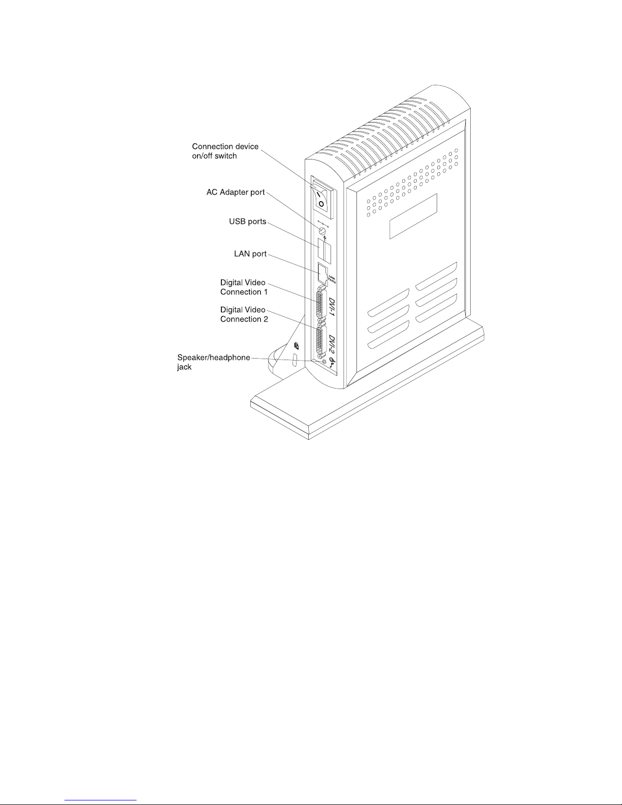
The following illustration shows the connectors on the rear of the connection device.
Connection device on/off switch: Press this switch to power-on or power-off the
IBM CP20 Workstation Connection Device.
AC Adapter port: Connect the AC adapter to this connector to supply power to the
IBM CP20 Workstation Connection Device.
USB ports: Connector for a USB device, such as a mouse or keyboard.
LAN port: Connect your local area network cable to this connector.
Digital Video Connection 1: Connect a monitor to this connector. This connector is
the primary video connector.
Digital Video Connection 2: Connect a monitor to this connector.
Speaker/headphone: Connect a speaker or headphones to this connector.
Chapter 1. Introduction 3
Page 14

4 IBM CP20 Workstation Connection Device: Installation Instructions
Page 15

Chapter 2. Installing the CP20 Workstation Connection Device
1. Connect a monitor to the workstation connection device. The workstation
connection device can support up to two monitors.
v Single monitor: If you will be using a single monitor, connect the monitor to
DVI connector 2. DVI connector 2 is towards the bottom of the rear of the
workstation connection device.
v Dual monitors: If you will be connecting two monitors to the workstation
connection device, the monitor connected to DVI connector 1 will be the
primary monitor.
Note: See “Configuring single and dual monitor support” on page 6 for
additional information about configuring monitors on the workstation
connection device.
2. Connect a USB keyboard and mouse to any of the USB connectors on the front
or on the rear of the workstation connection device. There are four USB ports
on the workstation connection device, including two on the front and two on the
back.
Note: The keyboard and mouse sensitivity can be changed. See “Adjusting
keyboard and mouse sensitivity” on page 14 for information on how to
change the keyboard and mouse sensitivity.
3. Connect an Ethernet cable to the LAN connector on the back of the connection
device. Complete the connection at the switch module associated with the
compression card Network Interface Controller (NIC) in the host system. The
compression card is also known as the I/O graphics and transmission adapter.
Note: By default, the connection device communicates with the host system
through the switch module installed in I/O bay 2 of the BladeCenter unit.
To use a switch module in I/O bay 1, change that setting by booting the
host system, then press F1 to enter the Configuration/Setup Utility. Select
Advanced Setup, then Ethernet I/O Module Configuration. Use the
arrow keys to change which I/O module should interface with the
compression card in the host system.
4. Connect any optional devices:
v Connect any other USB devices to any of the USB connectors on the front or
rear of the connection device.
Note: Audio function is disabled by default. To enable audio, see “Enabling
HD audio” on page 14.
v Connect speakers to the speaker or headphone jacks on the front or the rear
of the connection device.
v Connect a headphone to the speaker or headphone jack on the front or the
rear of the connection device.
5. Connect the monitor power cord to an ac power source.
6. Connect the connection device power cord to a properly grounded ac power
source.
7. Turn on the monitor; then, turn on the connection device by pressing the
connection device on/off switch to the on position.
© Copyright IBM Corp. 2008 5
Page 16

Configuring single and dual monitor support
Your connection device features two digital video interface (DVI) connectors. See
the tables below that apply for your connection device to determine which
connectors you want to use, then connect the monitor or monitors to the connection
device. If the signal cable on your monitor has a VGA-type connector, you can use
a DVI-to-VGA cable connector to connect the monitor to the connection device DVI
connector.
Note: When using a CRT monitor, the maximum video resolution for the connection
device is 1280x1024 at 85Hz.
When using dual monitors, you can use both monitors to display an extended
desktop. You will need to configure the video driver in the operating system on the
host system for dual monitor support. For more information on configuring the video
driver to use dual monitors, see the documentation for the operating system that is
installed on the host system.
Note: Enabling dual monitor configuration disables video redirection from a host
blade workstation to the management module on the BladeCenter unit. This
affects using KVM on the host blade workstation for remote control and for
using a console attached to the management module on the BladeCenter
unit.
The following three tables describe the functionality of the connection device when
connecting to a host system with the NVIDIA FX 1600M graphics adapter.
Connection Device with NVIDIA FX 1600M
Single monitor connected
to the top DVI connector
(See note 1)
On screen display Video No video N/A
POST Video No video No video
Desktop Video No video No video
Connection Device with NVIDIA FX 1600M
Single monitor connected
to the bottom DVI
connector (See note 1)
On screen display No video Video N/A
POST No video Video No video
Desktop No video Video Video (see note 2)
Connection Device with NVIDIA FX 1600M
Dual monitors
connected (See note
1) Top DVI Connector
On screen display Video No video N/A
POST Video No video Not supported
Desktop Video Video (See note 2) Not supported
Top DVI
Connector
Top DVI
Connector
Bottom DVI
Connector
Bottom DVI
Connector
Bottom DVI
Connector
AMM KVM
Management
Capability
AMM KVM
Management
Capability
AMM KVM
Management
Capability
6 IBM CP20 Workstation Connection Device: Installation Instructions
Page 17

The following three tables describe the functionality of the connection device when
connecting to a host system with the NVIDIA NVS 120M graphics adapter.
Connection Device with NVIDIA NVS 120M
Single monitor connected
to the top DVI connector
(See note 1)
On screen display Video No video N/A
POST Video No video No video
Desktop Video No video No video
Connection Device with NVIDIA NVS 120M
Single monitor connected
to the bottom DVI
connector (See note 1)
On screen display No video Video N/A
POST No video Video Video
Desktop No video Video Video (see note 2)
Connection Device with NVIDIA NVS 120M
Dual monitors
connected (See note
1) Top DVI Connector
On screen display Video No video N/A
POST Video Not supported
Desktop Video Video (See note 2) Not supported
Top DVI
Connector
Top DVI
Connector
Bottom DVI
Connector
Bottom DVI
Connector
Bottom DVI
Connector
AMM KVM
Management
Capability
AMM KVM
Management
Capability
AMM KVM
Management
Capability
Notes:
1. Monitor emulation must be enabled in the compression card settings on the host
system. Monitor emulation is enabled when configuring a session, for more
information see Chapter 3, “Setting up the connection between the connection
device and the host system,” on page 9. When monitor emulation is enabled,
KVM access for the host system is not available.
2. When using dual monitors, the primary video connector is the top DVI
connector. You must configure the desktop to support dual monitors through the
video driver settings in the operating system.
3. The bottom DVI connector must be used when administrator access is also
required through remote control or KVM. For remote control and KVM access,
note the supported resolutions listed in the remote control session. See the
"IBM BladeCenter Management Module User's Guide" for a list of supported
resolutions when accessing the BladeCenter unit using remote control through
the management module.
Chapter 2. Installing the CP20 Workstation Connection Device 7
Page 18

8 IBM CP20 Workstation Connection Device: Installation Instructions
Page 19

Chapter 3. Setting up the connection between the connection
device and the host system
It is recommended to update the firmware on the host system and on the
connection device before setting up the connection. For more information, see
“Updating the IBM CP20 Workstation Connection Device firmware” on page 16 and
"Updating the compression card firmware" in the "Installation and User's Guide" for
your host system.
By default, the connection device is configured to use DHCP. To use static IP
addresses, follow the instructions in “Setting up the connection using static IP
addresses” on page 10.
Setting up the connection using DHCP
To set up a remote session using DHCP, complete the following steps:
1. Turn on the host system and press F1 to start the Configuration/Setup Utility
program.
Note: Use the keyboard, video, and mouse connected to the management
module in the BladeCenter unit to configure the host system.
2. Select Advanced Setup→ Compression Card Network Configuration.
3. Note the MAC address and IP address of the compression card.
4. Press and hold the power-control button on the host system for more than 5
seconds to turn it off.
5. Turn on the connection device. The workstation interface, On Screen Display
(OSD), will load.
6. In the workstation interface, select Options→ Configuration.
7. Note the IP address of the connection device.
8. Click the Session tab; then, click Unlock and type your password. The default
password is PASSW0RD, with all uppercase letters and the numeral zero.
9. Type the IP address and MAC address of the compression card, and click
Apply.
10. Click the Discovery tab; then, clear the Enable Host Discovery check box
and click OK.
11. Click Options, Information. Note the MAC address of the connection device.
The MAC address is also available from a label on the connection device.
12. Turn off and turn on the connection device.
13. On a system (other than the blade server to which you are connecting the
connection device) that is on the same subnet as the compression card, open
a Web browser.
14. Direct the Web browser to the IP address of the compression card. The
compression card Web interface opens.
15. In the compression card Web interface, type your password and click Log In;
then, click Configuration→ Session.
16. Clear the Accept Any Peer check box.
17. Type the MAC address of the connection device, and click Apply.
© Copyright IBM Corp. 2008 9
Page 20

18. Click Configuration; then, click Monitor Emulation.
Note: When monitor emulation is enabled, KVM access for the host system is
not available.
19. Enable monitor emulation for each DVI connector in use on the connection
device.
20. Click Apply.
21. Click Reset.
22. If the host system is on, shut down the host system.
23. Go to the workstation connection device and click Connect. This will power on
the host system and allow you to see the system as it goes through POST.
Setting up the connection using static IP addresses
To set up a remote session using static IP addresses, complete the following steps:
1. Turn on the host system and press F1 to start the Configuration/Setup Utility
program.
Note: Use the keyboard, video, and mouse connected to the management
module in the BladeCenter unit to configure the host system.
2. Select Advanced Setup → Compression Card Network Configuration.
3. Change the compression card IP address to static.
4. Type the IP address, subnet mask, and gateway of the compression card.
5. Select Save Network Settings in Compression Card and press Enter. Then,
press Enter again to continue.
6. Note the MAC address and IP address of the compression card.
7. Exit the Configuration/Setup Utility program and save the settings.
8. Press and hold the power-control button on the host system for more than 5
seconds to turn it off.
9. Turn on the connection device. The workstation interface, On Screen Display
(OSD), will load.
10. Go to the workstation connection device; then, click Options, Configuration,
then Unlock.
11. Type your password. The default password is PASSW0RD, with all uppercase
letters and the numeral zero.
12. Clear the Enable DHCP check box.
13. Type the IP address, subnet mask, and gateway of the connection device.
Important: Make sure that the IP addresses of the compression card on the
14. Type the IP address and MAC address of the compression card, and click
Apply.
15. Click the Discovery tab; then, clear the Enable Host Discovery check box
and click OK.
16. Click Options, then Information. Note the MAC address of the connection
device. The MAC address is also available from a label on the connection
device.
10 IBM CP20 Workstation Connection Device: Installation Instructions
host system and the connection device are on the same network.
If they are not, the connection will fail. Use the PING utility on the
workstation connection device to verify that the IP address of the
compression card on the host system is accessible. For more
information, see “Ping tool” on page 15.
Page 21

17. Turn off and turn on the connection device.
18. On a system (other than the blade server to which you are connecting the
connection device) that is on the same subnet as the compression card, open
a Web browser.
19. Direct the Web browser to the IP address of the compression card. The
compression card Web interface opens.
20. In the compression card Web interface, type your password and click Log In;
then, click Configuration Session.
21. Clear the Accept Any Peer check box.
22. Type the MAC address of the connection device, and click Apply.
23. Click Configuration; then, click Monitor Emulation.
Note: When monitor emulation is enabled, KVM access for the host system is
not available.
24. Enable monitor emulation for each DVI connector in use on the connection
device.
25. Click Apply.
26. Click Reset.
27. If the host system is on, shut down the host system.
28. Go to the workstation connection device and click Connect. This will power on
the host system and allow you to see the system as it goes through POST.
Chapter 3. Setting up the connection between the connection device and the host system 11
Page 22

12 IBM CP20 Workstation Connection Device: Installation Instructions
Page 23

Chapter 4. Using the connection device
Starting a remote session
After the a session has been setup, the workstation connection device is ready to
connect to the host system. For more information on setting up a session, see
Chapter 3, “Setting up the connection between the connection device and the host
system,” on page 9.
Turn on the workstation connection device by pressing the connection device on/off
switch to the on position. Once the IBM workstation connection device boot process
is finished, the workstation interface is displayed. When a network connection has
been established, the network icon in the lower-right corner of the user interface is
displayed without a red X. If the network icon is displayed with a red "X", the
network connection has not been established.
X
For information about solving connection problems, see Chapter 5, “Solving
problems,” on page 15.
Press the remote host system on/off button on the front of the connection device to
turn the host system on or off. To start a session between the connection device
and a host system, click Connect in the workstation interface. To disconnect the
connection device from the host system, press the disconnect button.
© Copyright IBM Corp. 2008 13
Page 24

Adjusting keyboard and mouse sensitivity
The keyboard and mouse sensitivity for the workstation-connection-device interface
may be changed. These changes do not affect the keyboard and mouse sensitivity
once a remote session is started. See the documentation for the operating system
on the host system for information on how to change the keyboard and mouse
sensitivity when connected to the host system.
To change the keyboard sensitivity in the workstation-connection-device interface:
1. Click Options, User Settings, then click the Keyboard tab.
2. Use the mouse to slide the arrow to change the keyboard repeat delay and the
keyboard repeat rate.
3. Click Apply to activate the new setting.
To change the mouse sensitivity in the workstation-connection-device interface:
1. Click Options, then User Settings.
2. Use the mouse to slide the arrow to change the mouse speed.
3. Click Apply to activate the new setting.
Enabling HD audio
Audio is disabled by default. To use HD audio, you must enable it in both the
connection device and the compression card.
1. Turn on the connection device and the host system.
2. On a system (other than the host system to which you are connecting the
connection device) that is on the same subnet as the compression card and
connection device, open a Web browser.
3. Direct the Web browser to the IP address of the connection device. The
connection device Web interface opens.
4. In the connection device Web interface, type your password and click Log In;
then, click Permissions → Audio
5. Select the check box to enable HD audio.
6. Select the check box to enable audio compression.
7. Click Apply; then, click Reset.
8. Direct the Web browser to the IP address of the compression card. The
compression card Web interface opens.
9. In the compression card Web interface, type your password and click Log In,
Permissions; then, click Audio.
10. Select the check box to enable HD audio.
11. Select the check box to enable audio compression.
12. Click Apply; then, click Reset.
13. Restart the host system to apply the changes.
14 IBM CP20 Workstation Connection Device: Installation Instructions
Page 25

Chapter 5. Solving problems
The workstation interface has diagnostic tools to help you solve connection
problems. To use the diagnostic tools in the workstation interface, click Options,
Diagnostics; then, click the Event log tab or the Ping tab.
Note: The workstation interface consists of the On Screen Display (OSD) utility
which runs when the connection device is turned on.
Event log
Scroll to the bottom of the event log to view the most recent events. For example,
the event log might indicate that the IP address could not be assigned because of a
DHCP lease error. In that case, refer to the DHCP server to verify that a sufficient
number of IP addresses are available. To view the event log for the workstation
connection device, click Options, Diagnostics, then Event Log.
Ping tool
The Ping tool can be very helpful in isolating a network connectivity problem
between the connection device and the host system. You can use the ping tool to
verify that the host system is online and reachable from the network segment that
the connection device is on. In the ping tool, type the IP address of the
compression card in the host system and click Start to send ICMP request packets
to the host system. If the host system is online, it responds and the responses are
recorded in the ping tool. To stop the ping tool, click Stop. If pinging the
compression card in the host system fails, the compression card may not be on the
same subnet as the workstation connection device or the host system is not
operating correctly. See the "Installation and User Guide' for the host system for
information on troubleshooting the compression card.
You can also ping the IP address of the gateway or another device within the same
subnet to test if the LAN cable or network issue exists. If pinging the gateway or
another device on the subnet fails, reseat the LAN cable. If pinging the gateway or
another device still fails, contact your network administrator.
© Copyright IBM Corp. 2008 15
Page 26

USB peripherals
If a keyboard, mouse, or other USB peripheral is not working, use the following
steps to troubleshoot the problem.
1. If the USB device has an on/off switch, turn the device off and then turn it back
on.
2. Reseat the USB device.
3. Install the USB device into another USB port on the workstation connection
device. If the USB device works in another USB port, the original USB port
might be failing.
4. Configure the USB permissions on the workstation connection device to enable
support for all USB devices.
a. Open a Web browser from another system on the same subnet as the
workstation connection device.
b. Direct the Web browser to the IP address of the workstation connection
device.
c. Login to the workstation-connection-device interface.
d. Click Permissions, then USB.
e. Configure the first row of the USB device list:
1) To configure the "Entry Type" select Class.
2) To configure the "Device Class" select Any.
3) To configure the "Sub Class" select Any.
4) To configure the "Protocol" select Any.
5) Click Apply to use the new settings.
5. Install the USB device on another system.
v If it does not work, replace the USB device.
v If the USB device works on another system, the workstation connection
device might need to be replaced.
Updating the IBM CP20 Workstation Connection Device firmware
The following section gives information on how to update the firmware for the IBM
CP20 Workstation Connection Device.
Notes:
1. The workstation connection device and the compression card on the host
system must be at the same firmware levels. For information on how to verify
the firmware level and updated the firmware of the compression card, see the
"Installation and User's Guide" for your host system.
2. Changes are made periodically to the IBM Web site. The actual procedure might
vary slightly from what is described in this document.
Follow the steps below to update the firmware for your IBM CP20 Workstation
Connection Device:
1. Go to http://www.ibm.com/systems/support/.
2. Under Product support, click BladeCenter.
3. From the Product family menu, select CP20 Workstation Connection Device,
and click Go.
4. Download the firmware update to a management workstation such as a laptop.
16 IBM CP20 Workstation Connection Device: Installation Instructions
Page 27

Optional parts
5. Connect the management workstation directly to the IBM CP20 Workstation
Connection Device using an Ethernet cable.
6. Open a Web browser on the management workstation.
7. Direct the Web browser to the IP address of the connection device. The
connection device Web interface opens.
8. In the connection device Web interface, type your password and click Log In;
then, click Upload → Firmware and follow the on screen instructions to finish
the firmware update.
9. If the bootloader code is also available, click Upload Bootloader and follow the
on screen instructions to finish the bootloader update.
Part Part number
DVI to VGA cable connector 25R9042
1.8m, 2.5A/125V, NEMA 5-15P (US/Canada) Line Cord 43W6307
1.8m, 2.5A/250V, IRAM 2073 (Argentina) Line Cord 43W6308
1.8m, 2.5A/250V, AS/NZS 3112 (Australia) Line Cord 43W6309
1.8m, 2.5A/250V, CEE(7)-VII (Europe) Line Cord 43W6310
1.8m, 2.5A/250V, SABS 164 (S.Africa) Line Cord 43W6311
1.8m, 2.5A/250V, BS 1363/A (UK) Line Cord 43W6312
1.8m, 2.5A/250V, JIS C-8303 (Japan) Line Cord 43W6313
1.8m, 2.5A/250V, GB 2099.1 (China) Line Cord 43W6314
1.8m, 2.5A/250V, KSC 8305 (Korea) Line Cord 43W6315
1.8m, 2.5A/250V, IS 6538 (India) Line Cord 43W6316
1.8m, 2.5A/125V, NBR 6147 (Brazil) Line Cord 43W6317
1.8m, 2.5A/125V, CNS 10917-3 Taiwan Line Cord 43W6318
1.8m, 2.5A/250V, DK2-5a (Denmark) Line Cord 43W6345
1.8m, 2.5A/250V, 1011-S2 4507 (Switzerland) Line Cord 43W6346
1.8m, 2.5A/250V, CEI 23-15 (Chile/Italy) Line Cord 43W6347
1.8m, 2.5A/250V, SI 32 (Israel) Line Cord 43W6348
Chapter 5. Solving problems 17
Page 28

18 IBM CP20 Workstation Connection Device: Installation Instructions
Page 29

Appendix A. Getting help and technical assistance
If you need help, service, or technical assistance or just want more information
about IBM products, you will find a wide variety of sources available from IBM to
assist you. This section contains information about where to go for additional
information about IBM and IBM products, what to do if you experience a problem
with your system, and whom to call for service, if it is necessary.
Before you call
Before you call, make sure that you have taken these steps to try to solve the
problem yourself:
v Check all cables to make sure that they are connected.
v Check the power switches to make sure that the system and any optional
devices are turned on.
v Use the troubleshooting information in your system documentation, and use the
diagnostic tools that come with your system. Information about diagnostic tools is
in the Problem Determination and Service Guide on the IBM Documentation CD
that comes with your system.
v Go to the IBM support Web site at http://www.ibm.com/systems/support/ to check
for technical information, hints, tips, and new device drivers or to submit a
request for information.
You can solve many problems without outside assistance by following the
troubleshooting procedures that IBM provides in the online help or in the
documentation that is provided with your IBM product. The documentation that
comes with IBM systems also describes the diagnostic tests that you can perform.
Most systems, operating systems, and programs come with documentation that
contains troubleshooting procedures and explanations of error messages and error
codes. If you suspect a software problem, see the documentation for the operating
system or program.
Using the documentation
Information about your IBM system and preinstalled software, if any, or optional
device is available in the documentation that comes with the product. That
documentation can include printed documents, online documents, readme files, and
help files. See the troubleshooting information in your system documentation for
instructions for using the diagnostic programs. The troubleshooting information or
the diagnostic programs might tell you that you need additional or updated device
drivers or other software. IBM maintains pages on the World Wide Web where you
can get the latest technical information and download device drivers and updates.
To access these pages, go to http://www.ibm.com/systems/support/ and follow the
instructions. Also, some documents are available through the IBM Publications
Center at http://www.ibm.com/shop/publications/order/.
Getting help and information from the World Wide Web
On the World Wide Web, the IBM Web site has up-to-date information about IBM
systems, optional devices, services, and support. The address for IBM System x
and xSeries®information is http://www.ibm.com/systems/x/. The address for IBM
BladeCenter
for IBM IntelliStation®information is http://www.ibm.com/intellistation/.
© Copyright IBM Corp. 2008 19
®
information is http://www.ibm.com/systems/bladecenter/. The address
®
Page 30

You can find service information for IBM systems and optional devices at
http://www.ibm.com/systems/support/.
Software service and support
Through IBM Support Line, you can get telephone assistance, for a fee, with usage,
configuration, and software problems with System x and xSeries servers,
BladeCenter products, IntelliStation workstations, and appliances. For information
about which products are supported by Support Line in your country or region, see
http://www.ibm.com/services/sl/products/.
For more information about Support Line and other IBM services, see
http://www.ibm.com/services/, or see http://www.ibm.com/planetwide/ for support
telephone numbers. In the U.S. and Canada, call 1-800-IBM-SERV
(1-800-426-7378).
Hardware service and support
You can receive hardware service through your IBM reseller or IBM Services. To
locate a reseller authorized by IBM to provide warranty service, go to
http://www.ibm.com/partnerworld/ and click Find a Business Partner on the right
side of the page. For IBM support telephone numbers, see http://www.ibm.com/
planetwide/. In the U.S. and Canada, call 1-800-IBM-SERV (1-800-426-7378).
In the U.S. and Canada, hardware service and support is available 24 hours a day,
7 days a week. In the U.K., these services are available Monday through Friday,
from 9 a.m. to 6 p.m.
IBM Taiwan product service
IBM Taiwan product service contact information:
IBM Taiwan Corporation
3F, No 7, Song Ren Rd.
Taipei, Taiwan
Telephone: 0800-016-888
20 IBM CP20 Workstation Connection Device: Installation Instructions
Page 31

Appendix B. IBM Statement of Limited Warranty Z125-4753-09
08/2006
Part 1 - General Terms
Part 1 - General Terms
This Statement of Limited Warranty includes Part 1 - General Terms, Part 2 Country-unique Terms, and Part3-Warranty Information. The terms of Part 2
replace or modify those of Part 1.
The warranties provided by IBM in this Statement of Limited Warranty apply only to
Machines you purchase for your use, and not for resale. The term “Machine” means
an IBM machine, its features, conversions, upgrades, elements, or accessories, or
any combination of them. The term “Machine” does not include any software
programs, whether pre-loaded with the Machine, installed subsequently or
otherwise. NOTHING IN THIS STATEMENT OF LIMITED WARRANTY AFFECTS
ANY STATUTORY RIGHTS OF CONSUMERS THAT CANNOT BE WAIVED OR
LIMITED BY CONTRACT.
This Statement of Limited Warranty is available, in multiple languages, at the
following IBM Internet website: http://www.ibm.com/servers/support/
machine_warranties/.
What this Warranty Covers
IBM warrants that each Machine is free from defects in materials and workmanship
and conforms to its Specifications. “Specifications” is information specific to a
Machine in a document entitled “Official Published Specifications” which is available
upon request.
During the warranty period, IBM provides repair and exchange service for the
Machine under the type of warranty service IBM designates for the Machine. The
warranty period for the Machine is a fixed period starting on its original Date of
Installation. The date on your purchase invoice or sales receipt is the Date of
Installation unless IBM or your reseller informs you otherwise. The warranty period,
type of warranty, and service level that apply to your Machine are designated in
Part 3.
Many features, conversions, or upgrades involve the removal of parts and their
return to IBM. An IBM part that replaces a removed part will assume the warranty
service status of the removed part. An IBM part that is added to a Machine without
replacing a previously-installed part is subject to warranty effective on its Date of
Installation. Unless IBM specifies otherwise, the warranty period, type of warranty,
and service level of such part is the same as the Machine on which it is installed.
Unless IBM specifies otherwise, these warranties apply only in the country or region
in which you purchased the Machine.
THESE WARRANTIES ARE YOUR EXCLUSIVE WARRANTIES AND REPLACE
ALL OTHER WARRANTIES OR CONDITIONS, EXPRESS OR IMPLIED,
INCLUDING, BUT NOT LIMITED TO, THE IMPLIED WARRANTIES OR
CONDITIONS OF MERCHANTABILITY AND FITNESS FOR A PARTICULAR
PURPOSE. SOME STATES OR JURISDICTIONS DO NOT ALLOW THE
EXCLUSION OF EXPRESS OR IMPLIED WARRANTIES, SO THE ABOVE
© Copyright IBM Corp. 2008 21
Page 32

EXCLUSION MAY NOT APPLY TO YOU. IN THAT EVENT, SUCH WARRANTIES
ARE LIMITED IN DURATION TO THE WARRANTY PERIOD. NO WARRANTIES
APPLY AFTER THAT PERIOD. SOME STATES OR JURISDICTIONS DO NOT
ALLOW LIMITATIONS ON HOW LONG AN IMPLIED WARRANTY LASTS, SO
THE ABOVE LIMITATION MAY NOT APPLY TO YOU.
What this Warranty Does not Cover
This warranty does not cover the following:
1. failure or damage resulting from misuse (including but not limited to use of any
Machine capacity or capability, other than that authorized by IBM in writing),
accident, modification, unsuitable physical or operating environment, or improper
maintenance by you;
2. failure caused by a product for which IBM is not responsible;
3. any non-IBM products, including those provided with, or installed on, an IBM
Machine at your request;
4. accessories, supply items and consumables (e.g. batteries and printer
cartridges), and structural parts (e.g. frames and covers);
5. service of Machine alterations; and
6. service of a Machine on which you are using capacity or capability, other than
that authorized by IBM in writing.
The warranty is voided by removal or alteration of identification labels on the
Machine or its parts.
IBM does not warrant uninterrupted or error-free operation of a Machine.
Any technical or other support provided for a Machine under warranty, such as
assistance with “how-to” questions and those regarding Machine set-up and
installation, is provided WITHOUT WARRANTIES OF ANY KIND.
How to Obtain Warranty Service
If the Machine does not function as warranted during the warranty period, contact
IBM or your reseller to obtain warranty service. Contact information for IBM is
provided in Part 3. If you do not register the Machine with IBM, you may be
required to present proof of purchase as evidence of your entitlement to warranty
service.
What IBM Will Do to Correct Problems
IBM will attempt to diagnose and resolve your problem over the telephone or
electronically by access to an IBM Internet website. Certain Machines contain
remote support capabilities for direct problem reporting, remote problem
determination and resolution with IBM. When you contact IBM for service, you must
follow the problem determination and resolution procedures that IBM specifies.
Following problem determination, if IBM determines on-site service is required, a
service technician will be scheduled for service at your location.
You are responsible for downloading or obtaining from IBM, and installing
designated Machine Code (microcode, basic input/output system code (called
“BIOS”), utility programs, device drivers, and diagnostics delivered with an IBM
Machine) and other software updates in a timely manner from an IBM Internet
22 IBM CP20 Workstation Connection Device: Installation Instructions
Page 33

website or from other electronic media, and following the instructions that IBM
provides. You may request IBM to install Machine Code changes, however, you
may be charged for that service.
Some parts of IBM Machines are designated as Customer Replaceable Units
(“CRUs”). If your problem can be resolved with a CRU (e.g., keyboard, memory,
hard disk drive), IBM will ship the CRU to you for you to install.
If the Machine does not function as warranted during the warranty period and your
problem cannot be resolved over the telephone or electronically, through your
application of Machine Code or software updates, or with a CRU, IBM or its
subcontractor or a reseller that has been approved by IBM to provide warranty
service, will either, at its discretion, 1) repair it to make it function as warranted, or
2) replace it with one that is at least functionally equivalent. If IBM or its
subcontractor or the reseller is unable to do either, you may return the Machine to
your place of purchase and your money will be refunded.
IBM or its subcontractor or the reseller will also manage and install selected
engineering changes that apply to the Machine.
Exchange of a Machine or Part
When the warranty service involves the exchange of a Machine or part, the item
IBM or its subcontractor or the reseller replaces becomes IBM's property and the
replacement becomes yours. You represent that all removed items are genuine and
unaltered. The replacement may not be new, but will be in good working order and
at least functionally equivalent to the item replaced. The replacement assumes the
warranty service status of the replaced item.
Your Additional Responsibilities
You agree:
1. before IBM or its subcontractor or the reseller exchanges a Machine or part, to
remove all features, parts, options, alterations, and attachments not under
warranty service and ensure that the Machine is free of any legal obligations or
restrictions that prevent its exchange;
2. to obtain authorization from the owner to have IBM or its subcontractor or the
reseller service a Machine that you do not own;
3. where applicable, before service is provided:
a. follow the service request procedures that IBM or its subcontractor or its
reseller provides;
b. backup and secure all programs, data, and funds contained in the Machine;
and
c. inform IBM or its subcontractor or the reseller of changes in the Machine's
location;
4. to provide IBM or its subcontractor or the reseller with sufficient and safe access
to your facilities to permit IBM to fulfill its obligations;
5. to allow IBM or its subcontractor or the reseller to install mandatory engineering
changes, such as those required for safety;
6. when the type of warranty service requires that you deliver a failing Machine to
IBM, you agree to ship it suitably packaged, as IBM specifies, to a location IBM
designates. After the Machine has been repaired or exchanged, IBM will return
the repaired Machine or provide a replacement Machine to you at its expense,
unless IBM specifies otherwise. IBM is responsible for loss of, or damage to,
your Machine only while it is 1) in IBM's possession or 2) in transit in those
cases where IBM is responsible for the transportation charges; and
Appendix B. IBM Statement of Limited Warranty Z125-4753-09 08/2006 23
Page 34

7. to securely erase from any Machine you return to IBM for any reason all
programs not provided by IBM with the Machine, and data, including without
limitation the following: 1) information about identified or identifiable individuals
or legal entities (“Personal Data”) and 2) your confidential or proprietary
information and other data. If removing or deleting Personal Data is not
possible, you agree to transform such information (e.g., by making it anonymous
or encrypting it) so that it no longer qualifies as Personal Data under applicable
law. You also agree to remove all funds from Machines returned to IBM. IBM is
not responsible for any funds, programs not provided by IBM with the Machine,
or data contained in a Machine that you return to IBM. You acknowledge that, to
perform its responsibilities under this Statement of Limited Warranty, IBM may
ship all or part of the Machine or its software to other IBM or third party
locations around the world, and you authorize IBM to do so.
Limitation of Liability
Circumstances may arise where, because of a default on IBM’s part or other
liability, you are entitled to recover damages from IBM. In each such instance,
regardless of the basis on which you are entitled to claim damages from IBM
(including fundamental breach, negligence, misrepresentation, or other contract or
tort claim), except for any liability that cannot be waived or limited by applicable
laws, IBM is liable for no more than:
1. damages for bodily injury (including death) and damage to real property and
tangible personal property; and
2. the amount of any other actual direct damages, up to the charges (if recurring,
12 months’ charges apply) for the Machine that is subject of the claim. For
purposes of this item, the term “Machine” includes Machine Code and Licensed
Internal Code (“LIC”).
This limit also applies to IBM’s suppliers, subcontractors, and resellers. It is the
maximum for which IBM and its suppliers, subcontractors and resellers are
collectively responsible.
UNDER NO CIRCUMSTANCES IS IBM OR ITS SUPPLIERS,
SUBCONTRACTORS, OR RESELLERS LIABLE FOR ANY OF THE FOLLOWING
EVEN IF INFORMED OF THEIR POSSIBILITY: 1) THIRD PARTY CLAIMS
AGAINST YOU FOR DAMAGES (OTHER THAN THOSE UNDER THE FIRST
ITEM LISTED ABOVE); 2) LOSS OF, OR DAMAGE TO, DATA; 3) SPECIAL,
INCIDENTAL, OR INDIRECT DAMAGES OR FOR ANY ECONOMIC
CONSEQUENTIAL DAMAGES; OR 4) LOST PROFITS, BUSINESS REVENUE,
GOODWILL OR ANTICIPATED SAVINGS. SOME STATES OR JURISDICTIONS
DO NOT ALLOW THE EXCLUSION OR LIMITATION OF INCIDENTAL OR
CONSEQUENTIAL DAMAGES, SO THE ABOVE LIMITATION OR EXCLUSION
MAY NOT APPLY TO YOU.
Governing Law
Both you and IBM consent to the application of the laws of the country in which you
acquired the Machine to govern, interpret, and enforce all of your and IBM’s rights,
duties, and obligations arising from, or relating in any manner to, the subject matter
of this Statement of Limited Warranty, without regard to conflict of law principles.
THESE WARRANTIES GIVE YOU SPECIFIC LEGAL RIGHTS AND YOU MAY
ALSO HAVE OTHER RIGHTS WHICH VARY FROM STATE TO STATE OR
JURISDICTION TO JURISDICTION.
24 IBM CP20 Workstation Connection Device: Installation Instructions
Page 35

Jurisdiction
All of our rights, duties, and obligations are subject to the courts of the country in
which you acquired the Machine.
Part 2 - Country-unique Terms
AMERICAS
Jurisdiction: The following sentence is added to this section as it applies to
countries in bold print below:
Any litigation arising from this Statement of Limited Warranty will be settled
exclusively by 1) in Argentina; the Ordinary Commercial Court of the city of Buenos
Aires; 2) in Bolivia; the courts of the city of La Paz; 3) in Brazil; court of Rio de
Janeiro, RJ; 4) in Chile; the Civil Courts of Justice of Santiago; 5) in Colombia; the
Judges of the Republic of Colombia; 6) in Equador; the civil judges of Quito for
executory or summary proceedings (as applicable); 7) in Mexico; the courts located
in Mexico City, Federal District; 8) in Paraguay; the courts of the city of Asuncion;
9) in Peru; the judges and tribunals of the judicial district of Lima, Cercado; 10) in
Uruguay; the courts of the city of Montevideo; 11) in Venezuela; the courts of the
metropolitan area of the city of Caracas.
BRAZIL
Exchange of a Machine or Part: Delete the last sentence:
The replacement assumes the warranty service status of the replaced item.
CANADA
nd
What this Warranty Covers: The following replaces the 2
paragraph to this
section:
During the warranty period, IBM provides repair and exchange service for the
Machine under the type of warranty service IBM designates for the Machine. The
warranty period for the Machine is a fixed period starting on its original Date of
Installation. The date on your purchase invoice or sales receipt is the Date of
Installation unless IBM informs you otherwise. The warranty period, type of
warranty, and service level that apply to your Machine are designated in Part 3.
Limitation of Liability: The following replaces item 1 and item 2 of this section:
1. damages for bodily injury (including death) or physical harm to real property and
tangible personal property caused by IBM's negligence; and
2. the amount of any other actual direct damages, up to the greater of
$100,000.00 or the charges (if recurring, 12 months' charges apply) for the
Machine that is subject of the claim. For purposes of this item, the term
“Machine” includes Machine Code and Licensed Internal Code (“LIC”).
Governing Law: The following replaces “laws of the country in which you acquired
the Machine” in the first sentence:
laws in the Province of Ontario.
Appendix B. IBM Statement of Limited Warranty Z125-4753-09 08/2006 25
Page 36

PERU
Limitation of Liability: The following is added at the end of this section:
In accordance with Article 1328 of the Peruvian Civil Code the limitations and
exclusions specified in this section will not apply to damages caused by IBM’s willful
misconduct (“dolo”) or gross negligence (“culpa inexcusable”).
UNITED STATES
Governing Law: The following replaces “laws of the country in which you acquired
the Machine” in the first sentence:
laws of the State of New York
ASIA PACIFIC
AUSTRALIA
What this Warranty Covers: The following paragraph is added to this section:
The warranties specified in this Section are in addition to any rights you may have
under the Trade Practices Act 1974 or other similar legislation and are only limited
to the extent permitted by the applicable legislation.
Limitation of Liability: The following is added to this section:
Where IBM is in breach of a condition or warranty implied by the Trade Practices
Act 1974 or other similar legislation, IBM’s liability is limited to the repair or
replacement of the goods or the supply of equivalent goods. Where that condition
or warranty relates to right to sell, quiet possession or clear title, or the goods are of
a kind ordinarily acquired for personal, domestic or household use or consumption,
then none of the limitations in this paragraph apply.
Governing Law: The following replaces “laws of the country in which you acquired
the Machine” in the first sentence:
laws of the State or Territory
CAMBODIA AND LAOS
Governing Law: The following replaces “laws of the country in which you acquired
the Machine” in the first sentence:
laws of the State of New York, United States of America
CAMBODIA, INDONESIA, AND LAOS
Arbitration: The following is added under this heading:
Disputes arising out of or in connection with this Statement of Limited Warranty
shall be finally settled by arbitration which shall be held in Singapore in accordance
with the Arbitration Rules of Singapore International Arbitration Center (“SIAC
Rules”) then in effect. The arbitration award shall be final and binding for the parties
without appeal and shall be in writing and set forth the findings of fact and the
conclusions of law.
26 IBM CP20 Workstation Connection Device: Installation Instructions
Page 37

The number of arbitrators shall be three, with each side to the dispute being entitled
to appoint one arbitrator. The two arbitrators appointed by the parties shall appoint
a third arbitrator who shall act as chairman of the proceedings. Vacancies in the
post of chairman shall be filled by the president of the SIAC. Other vacancies shall
be filled by the respective nominating party. Proceedings shall continue from the
stage they were at when the vacancy occurred.
If one of the parties refuses or otherwise fails to appoint an arbitrator within 30 days
of the date the other party appoints its, the first appointed arbitrator shall be the
sole arbitrator, provided that the arbitrator was validly and properly appointed.
All proceedings shall be conducted, including all documents presented in such
proceedings, in the English language. The English language version of this
Statement of Limited Warranty prevails over any other language version.
HONG KONG S.A.R.
As applies to transactions initiated and performed in Hong Kong S.A.R., phrases
throughout this Agreement containing the word “country” (for example, “country of
purchase” and “country of Installation”) are replaced with “Hong Kong S.A.R.”
INDIA
Limitation of Liability: The following replaces items 1 and 2 of this section:
1. liability for bodily injury (including death) or damage to real property and tangible
personal property will be limited to that caused by IBM’s negligence; and
2. as to any other actual damage arising in any situation involving nonperformance
by IBM pursuant to, or in any way related to the subject of this Statement of
Limited Warranty, the charge paid by you for the individual Machine that is the
subject of the claim. For purposes of this item, the term “Machine” includes
Machine Code and Licensed Internal Code (“LIC”).
Arbitration: The following is added under this heading:
Disputes arising out of or in connection with this Statement of Limited Warranty
shall be finally settled by arbitration which shall be held in Bangalore, India in
accordance with the laws of India then in effect. The arbitration award shall be final
and binding for the parties without appeal and shall be in writing and set forth the
findings of fact and the conclusions of law.
The number of arbitrators shall be three, with each side to the dispute being entitled
to appoint one arbitrator. The two arbitrators appointed by the parties shall appoint
a third arbitrator who shall act as chairman of the proceedings. Vacancies in the
post of chairman shall be filled by the president of the Bar Council of India. Other
vacancies shall be filled by the respective nominating party. Proceedings shall
continue from the stage they were at when the vacancy occurred.
If one of the parties refuses or otherwise fails to appoint an arbitrator within 30 days
of the date the other party appoints its, the first appointed arbitrator shall be the
sole arbitrator, provided that the arbitrator was validly and properly appointed.
All proceedings shall be conducted, including all documents presented in such
proceedings, in the English language. The English language version of this
Statement of Limited Warranty prevails over any other language version.
Appendix B. IBM Statement of Limited Warranty Z125-4753-09 08/2006 27
Page 38

JAPAN
Governing Law: The following sentence is added to this section:
Any doubts concerning this Statement of Limited Warranty will be initially resolved
between us in good faith and in accordance with the principle of mutual trust.
MACAU S.A.R.
As applies to transactions initiated and performed in Macau S.A.R., phrases
throughout this Agreement containing the word “country” (for example, “country of
purchase” and “country of Installation”) are replaced with “Macau S.A.R.”
MALAYSIA
Limitation of Liability: The word “SPECIAL” in item 3 of the fifth paragraph is
deleted.
NEW ZEALAND
What this Warranty Covers: The following paragraph is added to this section:
The warranties specified in this section are in addition to any rights you may have
under the Consumer Guarantees Act 1993 or other legislation which cannot be
excluded or limited. The Consumer Guarantees Act 1993 will not apply in respect of
any goods which IBM provides, if you require the goods for the purposes of a
business as defined in that Act.
Limitation of Liability: The following is added to this section:
Where Machines are not acquired for the purposes of a business as defined in the
Consumer Guarantees Act 1993, the limitations in this Section are subject to the
limitations in that Act.
PEOPLE’S REPUBLIC OF CHINA (PRC)
Governing Law: The following replaces “laws of the country in which you acquired
the Machine” in the first sentence:
laws of the State of New York, United States of America (except when local law
requires otherwise).
PHILIPPINES
Limitation of Liability: Item 3 in the fifth paragraph is replaced by the following:
SPECIAL (INCLUDING NOMINAL AND EXEMPLARY DAMAGES), MORAL,
INCIDENTAL, OR INDIRECT DAMAGES FOR ANY ECONOMIC
CONSEQUENTIAL DAMAGES; OR
Arbitration: The following is added under this heading:
Disputes arising out of or in connection with this Statement of Limited Warranty
shall be finally settled by arbitration which shall be held in Metro Manila, Philippines
in accordance with the laws of the Philippines then in effect. The arbitration award
28 IBM CP20 Workstation Connection Device: Installation Instructions
Page 39

shall be final and binding for the parties without appeal and shall be in writing and
set forth the findings of fact and the conclusions of law.
The number of arbitrators shall be three, with each side to the dispute being entitled
to appoint one arbitrator. The two arbitrators appointed by the parties shall appoint
a third arbitrator who shall act as chairman of the proceedings. Vacancies in the
post of chairman shall be filled by the president of the Philippine Dispute Resolution
Center, Inc. Other vacancies shall be filled by the respective nominating party.
Proceedings shall continue from the stage they were at when the vacancy occurred.
If one of the parties refuses or otherwise fails to appoint an arbitrator within 30 days
of the date the other party appoints its, the first appointed arbitrator shall be the
sole arbitrator, provided that the arbitrator was validly and properly appointed.
All proceedings shall be conducted, including all documents presented in such
proceedings, in the English language. The English language version of this
Statement of Limited Warranty prevails over any other language version.
SINGAPORE
Limitation of Liability: The words “SPECIAL” and “ECONOMIC” in item 3 in the
fifth paragraph are deleted.
EUROPE, MIDDLE EAST, AFRICA (EMEA)
THE FOLLOWING TERMS APPLY TO ALL EMEA COUNTRIES:
The terms of this Statement of Limited Warranty apply to Machines purchased from
IBM or an IBM reseller.
How to Obtain Warranty Service:
Add the following paragraph in Western Europe (Andorra, Austria, Belgium,
Cyprus, Czech Republic, Denmark, Estonia, Finland, France, Germany, Greece,
Hungary, Iceland, Ireland, Italy, Latvia, Liechtenstein, Lithuania, Luxembourg, Malta,
Monaco, Netherlands, Norway, Poland, Portugal, San Marino, Slovakia, Slovenia,
Spain, Sweden, Switzerland, United Kingdom, Vatican State, and any country
subsequently added to the European Union, as from the date of accession):
The warranty for Machines acquired in Western Europe shall be valid and
applicable in all Western Europe countries provided the Machines have been
announced and made available in such countries.
If you purchase a Machine in one of the Western European countries, as defined
above, you may obtain warranty service for that Machine in any of those countries
from either (1) an IBM reseller approved to perform warranty service or (2) from
IBM, provided the Machine has been announced and made available by IBM in the
country in which you wish to obtain service.
If you purchase a Machine in a Middle East or African country, you may obtain
warranty service for that Machine from the IBM entity within the country of
purchase, if that IBM entity provides warranty service in that country, or from an
IBM reseller, approved by IBM to perform warranty service on that Machine in that
country. Warranty service in Africa is available within 50 kilometers of an IBM
approved service provider. You are responsible for transportation costs for Machines
located outside 50 kilometers of an IBM approved service provider.
Appendix B. IBM Statement of Limited Warranty Z125-4753-09 08/2006 29
Page 40

Governing Law: The phrase “the laws of the country in which you acquired the
Machine” is replaced by:
1) “the laws of Austria” in Albania, Armenia, Azerbaijan, Belarus,
Bosnia-Herzegovina, Bulgaria, Croatia, Georgia, Hungary, Kazakhstan,
Kyrgyzstan, FYR Macedonia, Moldova, Montenegro, Poland, Romania, Russia,
Serbia, Slovakia, Slovenia, Tajikistan, Turkmenistan, Ukraine, and Uzbekistan;
2) “the laws of France” in Algeria, Benin, Burkina Faso, Cameroon, Central
African Republic, Chad, Comoros, Congo Republic, Djibouti, Democratic
Republic of Congo, Equatorial Guinea, French Guiana, French Polynesia,
Gabon, Gambia, Guinea, Guinea-Bissau, Ivory Coast, Lebanon, Libya,
Madagascar, Mali, Mauritania, Mauritius, Mayotte, Morocco, New Caledonia,
Niger, Reunion, Senegal, Seychelles, Togo, Tunisia, Vanuatu, and Wallis &
Futuna; 3) “the laws of Finland” in Estonia, Latvia, and Lithuania; 4) “the laws of
England” in Angola, Bahrain, Botswana, Burundi, Egypt, Eritrea, Ethiopia,
Ghana, Jordan, Kenya, Kuwait, Liberia, Malawi, Malta, Mozambique, Nigeria,
Oman, Pakistan, Qatar, Rwanda, Sao Tome, Saudi Arabia, Sierra Leone,
Somalia, Tanzania, Uganda, United Arab Emirates, the United Kingdom, West
Bank/Gaza, Yemen, Zambia, and Zimbabwe; and 5) “the laws of South Africa” in
South Africa, Namibia, Lesotho and Swaziland.
Jurisdiction: The following exceptions are added to this section:
1) In Austria the choice of jurisdiction for all disputes arising out of this Statement
of Limited Warranty and relating thereto, including its existence, will be the
competent court of law in Vienna, Austria (Inner-City); 2) in Angola, Bahrain,
Botswana, Burundi, Egypt, Eritrea, Ethiopia, Ghana, Jordan, Kenya, Kuwait,
Liberia, Malawi, Malta, Mozambique, Nigeria, Oman, Pakistan, Qatar, Rwanda,
Sao Tome, Saudi Arabia, Sierra Leone, Somalia, Tanzania, Uganda, United
Arab Emirates, United Kingdom, West Bank/Gaza, Yemen, Zambia, and
Zimbabwe all disputes arising out of this Statement of Limited Warranty or related
to its execution, including summary proceedings, will be submitted to the exclusive
jurisdiction of the English courts; 3) in Belgium and Luxembourg, all disputes
arising out of this Statement of Limited Warranty or related to its interpretation or its
execution, the law, and the courts of the capital city, of the country of your
registered office and/or commercial site location only are competent; 4) in France,
Algeria, Benin, Burkina Faso, Cameroon, Central African Republic, Chad,
Comoros, Congo Republic, Djibouti, Democratic Republic of Congo,
Equatorial Guinea, French Guiana, French Polynesia, Gabon, Gambia, Guinea,
Guinea-Bissau, Ivory Coast, Lebanon, Libya, Madagascar, Mali, Mauritania,
Mauritius, Mayotte, Morocco, New Caledonia, Niger, Reunion, Senegal,
Seychelles, Togo, Tunisia, Vanuatu, and Wallis & Futuna all disputes arising out
of this Statement of Limited Warranty or related to its violation or execution,
including summary proceedings, will be settled exclusively by the Commercial Court
of Paris; 5) in South Africa, Namibia, Lesotho and Swaziland, both of us agree
to submit all disputes relating to this Statement of Limited Warranty to the
jurisdiction of the High Court in Johannesburg; 6) in Turkey all disputes arising out
of or in connection with this Statement of Limited Warranty shall be resolved by the
Istanbul Central (Sultanahmet) Courts and Execution Directorates of Istanbul, the
Republic of Turkey; 8) in each of the following specified countries, any legal claim
arising out of this Statement of Limited Warranty will be brought before, and settled
exclusively by, the competent court of a) Athens for Greece, b) Tel Aviv-Jaffa for
Israel, c) Milan for Italy, d) Lisbon for Portugal, and e) Madrid for Spain; and 8) in
the United Kingdom, both of us agree to submit all disputes relating to this
Statement of Limited Warranty to the jurisdiction of the English courts.
30 IBM CP20 Workstation Connection Device: Installation Instructions
Page 41

Arbitration: The following is added under this heading:
In Albania, Armenia, Azerbaijan, Belarus, Bosnia-Herzegovina, Bulgaria,
Croatia, Georgia, Hungary, Kazakhstan, Kyrgyzstan, Libya, FYR Macedonia,
Moldova, Montenegro, Poland, Romania, Russia, Serbia, Slovakia, Slovenia,
Tajikistan, Turkmenistan, Ukraine, and Uzbekistan all disputes arising out of this
Statement of Limited Warranty or related to its violation, termination or nullity will be
finally settled under the Rules of Arbitration and Conciliation of the International
Arbitral Center of the Federal Economic Chamber in Vienna (Vienna Rules) by three
arbitrators appointed in accordance with these rules. The arbitration will be held in
Vienna, Austria, and the official language of the proceedings will be English. The
decision of the arbitrators will be final and binding upon both parties. Therefore,
pursuant to paragraph 598 (2) of the Austrian Code of Civil Procedure, the parties
expressly waive the application of paragraph 595 (1) figure 7 of the Code. IBM may,
however, institute proceedings in a competent court in the country of installation.
In Estonia, Latvia and Lithuania all disputes arising in connection with this
Statement of Limited Warranty will be finally settled in arbitration that will be held in
Helsinki, Finland in accordance with the arbitration laws of Finland then in effect.
Each party will appoint one arbitrator. The arbitrators will then jointly appoint the
chairman. If arbitrators cannot agree on the chairman, then the Central Chamber of
Commerce in Helsinki will appoint the chairman.
EUROPEAN UNION (EU)
THE FOLLOWING TERMS APPLY TO ALL EU COUNTRIES:
The warranty for Machines acquired in EU countries is valid and applicable in all
EU countries provided the Machines have been announced and made available in
such countries.
DENMARK, FINLAND, GREECE, ITALY, NETHERLANDS, NORWAY, PORTUGAL,
SPAIN, SWEDEN AND SWITZERLAND
Limitation of Liability: The following replaces the terms of this section in its
entirety:
Except as otherwise provided by mandatory law:
1. IBM’s liability for any damages and losses that may arise as a consequence of
the fulfillment of its obligations under or in connection with this Statement of
Limited Warranty or due to any other cause related to this Statement of Limited
Warranty is limited to the compensation of only those damages and losses
proved and actually arising as an immediate and direct consequence of the
non-fulfillment of such obligations (if IBM is at fault) or of such cause, for a
maximum amount equal to the charges you paid for the Machine. For purposes
of this item, the term “Machine” includes Machine Code and Licensed Internal
Code (“LIC”).
The above limitation shall not apply to damages for bodily injuries (including
death) and damages to real property and tangible personal property for which
IBM is legally liable.
2. UNDER NO CIRCUMSTANCES IS IBM, OR ITS SUPPLIERS,
SUBCONTRACTORS, OR RESELLERS LIABLE FOR ANY OF THE
FOLLOWING, EVEN IF INFORMED OF THEIR POSSIBILITY: 1) LOSS OF,
OR DAMAGE TO, DATA; 2) INCIDENTAL OR INDIRECT DAMAGES, OR FOR
ANY ECONOMIC CONSEQUENTIAL DAMAGES; 3) LOST PROFITS, EVEN IF
THEY ARISE AS AN IMMEDIATE CONSEQUENCE OF THE EVENT THAT
Appendix B. IBM Statement of Limited Warranty Z125-4753-09 08/2006 31
Page 42

GENERATED THE DAMAGES; OR 4) LOSS OF BUSINESS, REVENUE,
GOODWILL, OR ANTICIPATED SAVINGS.
FRANCE AND BELGIUM
Limitation of Liability: The following replaces the terms of this section in its
entirety:
Except as otherwise provided by mandatory law:
1. IBM’s liability for any damages and losses that may arise as a consequence of
the fulfillment of its obligations under or in connection with this Statement of
Limited Warranty is limited to the compensation of only those damages and
losses proved and actually arising as an immediate and direct consequence of
the non-fulfillment of such obligations (if IBM is at fault), for a maximum amount
equal to the charges you paid for the Machine that has caused the damages.
For purposes of this item, the term “Machine” includes Machine Code and
Licensed Internal Code (“LIC”).
The above limitation shall not apply to damages for bodily injuries (including
death) and damages to real property and tangible personal property for which
IBM is legally liable.
2. UNDER NO CIRCUMSTANCES IS IBM, OR ITS SUPPLIERS,
SUBCONTRACTORS, OR RESELLERS LIABLE FOR ANY OF THE
FOLLOWING, EVEN IF INFORMED OF THEIR POSSIBILITY: 1) LOSS OF,
OR DAMAGE TO, DATA; 2) INCIDENTAL OR INDIRECT DAMAGES, OR FOR
ANY ECONOMIC CONSEQUENTIAL DAMAGES; 3) LOST PROFITS, EVEN IF
THEY ARISE AS AN IMMEDIATE CONSEQUENCE OF THE EVENT THAT
GENERATED THE DAMAGES; OR 4) LOSS OF BUSINESS, REVENUE,
GOODWILL, OR ANTICIPATED SAVINGS.
THE FOLLOWING TERMS APPLY TO THE COUNTRY SPECIFIED:
AUSTRIA AND GERMANY
What this Warranty Covers: The following replaces the first sentence of the first
paragraph of this section:
The warranty for an IBM Machine covers the functionality of the Machine for its
normal use and the Machine’s conformity to its Specifications.
The following paragraphs are added to this section:
The minimum warranty period for Machines is twelve months. In case IBM or your
reseller is unable to repair an IBM Machine, you can alternatively ask for a price
reduction as far as justified by the reduced value of the unrepaired Machine or ask
for a cancellation of the respective agreement for such Machine and get your
money refunded.
The second paragraph does not apply.
What IBM Will Do to Correct Problems: The following is added to this section:
During the warranty period, transportation for delivery of the failing Machine to IBM
will be at IBM's expense.
Limitation of Liability: The following paragraph is added to this section:
32 IBM CP20 Workstation Connection Device: Installation Instructions
Page 43

The limitations and exclusions specified in the Statement of Limited Warranty will
not apply to damages caused by IBM with fraud or gross negligence and for
express warranty.
The following sentence is added to the end of item 2:
IBM’s liability under this item is limited to the violation of essential contractual terms
in cases of ordinary negligence.
IRELAND
What this Warranty Covers: The following is added to this section:
Except as expressly provided in these terms and conditions or Section 12 of the
Sale of Goods Act 1893 as amended by the Sale of Goods and Supply of Services
Act, 1980 (“the 1980 Act”), all conditions or warranties (express or implied, statutory
or otherwise) are hereby excluded including, without limitation, any warranties
implied by the Sale of Goods Act 1893 as amended by the 1980 Act (including, for
the avoidance of doubt, section 39 of the 1980 Act).
Limitation of Liability: The following replaces the terms of this section in its
entirety:
For the purposes of this section, a “Default” means any act, statement, omission, or
negligence on the part of IBM in connection with, or in relation to, the subject matter
of this Statement of Limited Warranty in respect of which IBM is legally liable to
you, whether in contract or tort. A number of Defaults which together result in, or
contribute to, substantially the same loss or damage will be treated as one Default
occurring on the date of occurrence of the last such Default.
Circumstances may arise where, because of a Default, you are entitled to recover
damages from IBM.
This section sets out the extent of IBM’s liability and your sole remedy.
1. IBM will accept unlimited liability for death or personal injury caused by the
negligence of IBM.
2. Subject always to the Items for Which IBM is Not Liable below, IBM will
accept unlimited liability for physical damage to your tangible property resulting
from the negligence of IBM.
3. Except as provided in items 1 and 2 above, IBM’s entire liability for actual
damages for any one Default will not in any event exceed the greater of 1) EUR
125,000, or 2) 125% of the amount you paid for the Machine directly relating to
the Default.
Items for Which IBM is Not Liable
Save with respect to any liability referred to in item 1 above, under no
circumstances is IBM, its suppliers or resellers liable for any of the following, even if
IBM or they were informed of the possibility of such losses:
1. loss of, or damage to, data;
2. special, indirect, or consequential loss; or
3. loss of profits, business, revenue, goodwill, or anticipated savings.
Appendix B. IBM Statement of Limited Warranty Z125-4753-09 08/2006 33
Page 44

SOUTH AFRICA, NAMIBIA, BOTSWANA, LESOTHO AND SWAZILAND
Limitation of Liability: The following is added to this section:
IBM’s entire liability to you for actual damages arising in all situations involving
nonperformance by IBM in respect of the subject matter of this Statement of
Warranty will be limited to the charge paid by you for the individual Machine that is
the subject of your claim from IBM.
SWITZERLAND
Your Additional Responsibilities: The following sentence is added to this section:
Personal Data also includes information about you as a legal entity.
TURKEY
What this Warranty Covers: The following is added to this section:
The minimum warranty period for Machines is 2 years.
UNITED KINGDOM
Limitation of Liability: The following replaces the terms of this section in its
entirety:
For the purposes of this section, a “Default” means any act, statement, omission, or
negligence on the part of IBM in connection with, or in relation to, the subject matter
of this Statement of Limited Warranty in respect of which IBM is legally liable to
you, whether in contract or tort. A number of Defaults which together result in, or
contribute to, substantially the same loss or damage will be treated as one Default.
Circumstances may arise where, because of a Default, you are entitled to recover
damages from IBM.
This section sets out the extent of IBM’s liability and your sole remedy.
1. IBM will accept unlimited liability for:
a. death or personal injury caused by the negligence of IBM; and
b. any breach of its obligations implied by Section 12 of the Sale of Goods Act
1979 or Section 2 of the Supply of Goods and Services Act 1982, or any
statutory modification or re-enactment of either such Section.
2. IBM will accept unlimited liability, subject always to the Items for Which IBM is
Not Liable below, for physical damage to your tangible property resulting from
the negligence of IBM.
3. IBM’s entire liability for actual damages for any one Default will not in any event,
except as provided in items 1 and 2 above, exceed the greater of 1) Pounds
Sterling 75,000, or 2) 125% of the total purchase price payable or the charges
for the Machine directly relating to the Default.
These limits also apply to IBM’s suppliers and resellers. They state the maximum
for which IBM and such suppliers and resellers are collectively responsible.
34 IBM CP20 Workstation Connection Device: Installation Instructions
Page 45

Items for Which IBM is Not Liable
Save with respect to any liability referred to in item 1 above, under no
circumstances is IBM or any of its suppliers or resellers liable for any of the
following, even if IBM or they were informed of the possibility of such losses:
1. loss of, or damage to, data;
2. special, indirect, or consequential loss;
3. loss of profits, business, revenue, goodwill, or anticipated savings; or
4. third party claims against you for damages.
Part3-Warranty Information
IBM CP20 Workstation Connection Device
Country or Region
of Purchase Warranty Period
Worldwide 1 year Machine exchange Not applicable
* See “Types of Warranty Service” and “Service Levels” for explanations of warranty-service
types and service levels.
Type of Warranty
Service* Service Level*
Scheduling of a warranty service will depend upon the following: 1) the time your
request for service is received, 2) Machine technology, and 3) availability of parts.
Contact your local IBM representative or the subcontractor or reseller performing
services on behalf of IBM for country and location specific information.
Types of Warranty Service
1. Customer Replaceable Unit (“CRU”) Service
IBM provides replacement CRUs to you for you to install. CRU information and
replacement instructions are shipped with your Machine and are available from
IBM at any time on your request. CRUs are designated as being either Tier 1 or
a Tier 2 CRU. Installation of Tier 1 CRUs is your responsibility. If IBM installs a
Tier 1 CRU at your request, you will be charged for the installation. You may
install a Tier 2 CRU yourself or request IBM to install it, at no additional charge,
under the type of warranty service designated for your Machine. IBM specifies
in the materials shipped with a replacement CRU whether a defective CRU
must be returned to IBM. When return is required, 1) return instructions and a
container are shipped with the replacement CRU, and 2) you may be charged
for the replacement CRU if IBM does not receive the defective CRU within 15
days of your receipt of the replacement.
2. On-site Service
IBM or your reseller will either repair or exchange the failing Machine at your
location and verify its operation. You must provide suitable working area to allow
disassembly and reassembly of the IBM Machine. The area must be clean, well
lit and suitable for the purpose. For some Machines, certain repairs may require
sending the Machine to an IBM service center.
3. Courier or Depot Service
You will disconnect the failing Machine for collection arranged by IBM. IBM will
provide you with a shipping container for you to return your Machine to a
designated service center. A courier will pick up your Machine and deliver it to
Appendix B. IBM Statement of Limited Warranty Z125-4753-09 08/2006 35
Page 46

the designated service center. Following its repair or exchange, IBM will arrange
the return delivery of the Machine to your location. You are responsible for its
installation and verification.
4. Customer Carry-In or Mail-In Service
You will deliver or mail as IBM specifies (prepaid unless IBM specifies
otherwise) the failing Machine suitably packaged to a location IBM designates.
After IBM has repaired or exchanged the Machine, IBM will make it available for
your collection or, for Mail-in Service, IBM will return it to you at IBM’s expense,
unless IBM specifies otherwise. You are responsible for the subsequent
installation of the Machine and verification of its operation.
5. CRU and On-site Service*
This type of Warranty Service is a combination of Type 1 and Type 2 (see
above).
6. CRU and Courier or Depot Service*
This type of Warranty Service is a combination of Type 1 and Type 3 (see
above).
7. CRU and Customer Carry-In or Mail-In Service*
This type of Warranty Service is a combination of Type 1 and Type 4 (see
above).
8. Machine Exchange Service
IBM will initiate shipment of a replacement Machine to your location. You are
responsible for its installation and verification of its operation. You must pack the
failing Machine into the shipping container that contained the replacement
Machine and return the failing Machine to IBM. Transportation charges, both
ways, are paid by IBM. You may be charged for the replacement Machine if IBM
does not receive the failing Machine within 15 days of your receipt of the
replacement Machine.
(*) When a 5, 6, or 7 type of warranty service is listed, IBM will determine
which type of warranty service is appropriate for the repair.
Service Levels
Service levels specified below are response-time objectives only and are not
guarantees. The specified service level may not be available in all worldwide
locations. Charges may apply outside IBM's normal service area. Certain Machines
with a Same Day On-site response-time objective may require the installation and
use of remote connectivity tools and equipment for direct problem reporting, remote
problem determination and resolution.
1. Next Business Day (NBD), 9X5
After we receive your call, following problem determination, if IBM determines
on-site service is required, a service technician will be scheduled to arrive at
your location on the next business day. Service will be provided from 8:00 a.m.
to 5:00 p.m. in your local time zone, Monday through Friday, excluding holidays.
2. Same Business Day (SBD), 9X5
After we receive your call, following problem determination, if IBM determines
on-site service is required, a service technician will be scheduled to arrive at
your location within four hours. Service will be provided from 8:00 a.m. to 5:00
p.m. in your local time zone, Monday through Friday, excluding local IBM
holidays. If after 1:00 p.m. it is determined that on-site service is required, a
service technician will be scheduled to arrive the morning of the following
business day.
36 IBM CP20 Workstation Connection Device: Installation Instructions
Page 47

3. Same Day (SD), 24X7
After we receive your call, following problem determination, if IBM determines
on-site service is required, a service technician will be scheduled to arrive at
your location within four hours. This type of service will be provided 24 hours a
day, every day, including holidays.
IBM Contact Information
For IBM in Canada or the United States, call 1-800-IBM-SERV (or 1-800-426-7378).
For IBM in the European Union (EU), Asia Pacific, and Latin America countries,
contact IBM in that country or visit the following IBM Internet website:
http://www.ibm.com/servers/support/machine_warranties/.
Appendix B. IBM Statement of Limited Warranty Z125-4753-09 08/2006 37
Page 48

38 IBM CP20 Workstation Connection Device: Installation Instructions
Page 49

Appendix C. Notices
This information was developed for products and services offered in the U.S.A.
IBM may not offer the products, services, or features discussed in this document in
other countries. Consult your local IBM representative for information on the
products and services currently available in your area. Any reference to an IBM
product, program, or service is not intended to state or imply that only that IBM
product, program, or service may be used. Any functionally equivalent product,
program, or service that does not infringe any IBM intellectual property right may be
used instead. However, it is the user’s responsibility to evaluate and verify the
operation of any non-IBM product, program, or service.
IBM may have patents or pending patent applications covering subject matter
described in this document. The furnishing of this document does not give you any
license to these patents. You can send license inquiries, in writing, to:
IBM Director of Licensing
IBM Corporation
North Castle Drive
Armonk, NY 10504-1785
U.S.A.
INTERNATIONAL BUSINESS MACHINES CORPORATION PROVIDES THIS
PUBLICATION “AS IS” WITHOUT WARRANTY OF ANY KIND, EITHER EXPRESS
OR IMPLIED, INCLUDING, BUT NOT LIMITED TO, THE IMPLIED WARRANTIES
OF NON-INFRINGEMENT, MERCHANTABILITY OR FITNESS FOR A
PARTICULAR PURPOSE. Some states do not allow disclaimer of express or
implied warranties in certain transactions, therefore, this statement may not apply to
you.
Trademarks
This information could include technical inaccuracies or typographical errors.
Changes are periodically made to the information herein; these changes will be
incorporated in new editions of the publication. IBM may make improvements and/or
changes in the product(s) and/or the program(s) described in this publication at any
time without notice.
Any references in this information to non -IBM Web sites are provided for
convenience only and do not in any manner serve as an endorsement of those
Web sites. The materials at those Web sites are not part of the materials for this
IBM product, and use of those Web sites is at your own risk.
IBM may use or distribute any of the information you supply in any way it believes
appropriate without incurring any obligation to you.
The following terms are trademarks of International Business Machines Corporation
in the United States, other countries, or both:
IBM FlashCopy TechConnect
IBM (logo) i5/OS Tivoli
Active Memory IntelliStation Tivoli Enterprise
Active PCI NetBAY Update Connector
Active PCI-X Netfinity Wake on LAN
© Copyright IBM Corp. 2008 39
Page 50

AIX PowerExecutive XA-32
Alert on LAN Predictive Failure Analysis XA-64
BladeCenter ServeRAID X-Architecture
Chipkill ServerGuide XpandOnDemand
e-business logo ServerProven xSeries
Eserver System x
Intel, Intel Xeon, Itanium, and Pentium are trademarks of Intel Corporation in the
United States, other countries, or both.
Microsoft, Windows, and Windows NT are trademarks of Microsoft Corporation in
the United States, other countries, or both.
Adobe and PostScript are either registered trademarks or trademarks of Adobe
Systems Incorporated in the United States, other countries, or both.
UNIX is a registered trademark of The Open Group in the United States and other
countries.
Java and all Java-based trademarks are trademarks of Sun Microsystems, Inc. in
the United States, other countries, or both.
Adaptec and HostRAID are trademarks of Adaptec, Inc., in the United States, other
countries, or both.
Important notes
Linux is a registered trademark of Linus Torvalds in the United States, other
countries, or both.
Red Hat, the Red Hat “Shadow Man” logo, and all Red Hat-based trademarks and
logos are trademarks or registered trademarks of Red Hat, Inc., in the United States
and other countries.
Other company, product, or service names may be trademarks or service marks of
others.
Processor speed indicates the internal clock speed of the microprocessor; other
factors also affect application performance.
CD or DVD drive speed is the variable read rate. Actual speeds vary and are often
less than the possible maximum.
When referring to processor storage, real and virtual storage, or channel volume,
KB stands for 1024 bytes, MB stands for 1 048 576 bytes, and GB stands for
1 073 741 824 bytes.
When referring to hard disk drive capacity or communications volume, MB stands
for 1 000 000 bytes, and GB stands for 1 000 000 000 bytes. Total user-accessible
capacity can vary depending on operating environments.
Maximum internal hard disk drive capacities assume the replacement of any
standard hard disk drives and population of all hard disk drive bays with the largest
currently supported drives that are available from IBM.
40 IBM CP20 Workstation Connection Device: Installation Instructions
Page 51

Maximum memory might require replacement of the standard memory with an
optional memory module.
IBM makes no representation or warranties regarding non-IBM products and
services that are ServerProven
of merchantability and fitness for a particular purpose. These products are offered
and warranted solely by third parties.
IBM makes no representations or warranties with respect to non-IBM products.
Support (if any) for the non-IBM products is provided by the third party, not IBM.
Some software might differ from its retail version (if available) and might not include
user manuals or all program functionality.
Product recycling and disposal
This unit must be recycled or discarded according to applicable local and national
regulations. IBM encourages owners of information technology (IT) equipment to
responsibly recycle their equipment when it is no longer needed. IBM offers a
variety of product return programs and services in several countries to assist
equipment owners in recycling their IT products. Information on IBM product
recycling offerings can be found on IBM’s Internet site at http://www.ibm.com/ibm/
environment/products/index.shtml.
Esta unidad debe reciclarse o desecharse de acuerdo con lo establecido en la
normativa nacional o local aplicable. IBM recomienda a los propietarios de equipos
de tecnología de la información (TI) que reciclen responsablemente sus equipos
cuando éstos ya no les sean útiles. IBM dispone de una serie de programas y
servicios de devolución de productos en varios países, a fin de ayudar a los
propietarios de equipos a reciclar sus productos de TI. Se puede encontrar
información sobre las ofertas de reciclado de productos de IBM en el sitio web de
IBM http://www.ibm.com/ibm/environment/products/index.shtml.
®
, including but not limited to the implied warranties
Notice: This mark applies only to countries within the European Union (EU) and
Norway.
This appliance is labeled in accordance with European Directive 2002/96/EC
concerning waste electrical and electronic equipment (WEEE). The Directive
determines the framework for the return and recycling of used appliances as
applicable throughout the European Union. This label is applied to various products
to indicate that the product is not to be thrown away, but rather reclaimed upon end
of life per this Directive.
Appendix C. Notices 41
Page 52

Remarque : Cette marque s’applique uniquement aux pays de l’Union Européenne
et à la Norvège.
L’etiquette du système respecte la Directive européenne 2002/96/EC en matière de
Déchets des Equipements Electriques et Electroniques (DEEE), qui détermine les
dispositions de retour et de recyclage applicables aux systèmes utilisés à travers
l’Union européenne. Conformément à la directive, ladite étiquette précise que le
produit sur lequel elle est apposée ne doit pas être jeté mais être récupéré en fin
de vie.
In accordance with the European WEEE Directive, electrical and electronic
equipment (EEE) is to be collected separately and to be reused, recycled, or
recovered at end of life. Users of EEE with the WEEE marking per Annex IV of the
WEEE Directive, as shown above, must not dispose of end of life EEE as unsorted
municipal waste, but use the collection framework available to customers for the
return, recycling, and recovery of WEEE. Customer participation is important to
minimize any potential effects of EEE on the environment and human health due to
the potential presence of hazardous substances in EEE. For proper collection and
treatment, contact your local IBM representative.
Electronic emission notices
IBM CP20 Workstation Connection Device
Federal Communications Commission (FCC) statement
This equipment has been tested and found to comply with the limits for a Class B
digital device, pursuant to Part 15 of the FCC Rules. These limits are designed to
provide reasonable protection against harmful interference in a residential
installation. This equipment generates, uses, and can radiate radio frequency
energy and, if not installed and used in accordance with the instructions, may cause
harmful interference to radio communications. However, there is no guarantee that
interference will not occur in a particular installation. If this equipment does cause
harmful interference to radio or television reception, which can be determined by
turning the equipment off and on, the user is encouraged to try to correct the
interference by one or more of the following measures:
v Reorient or relocate the receiving antenna.
v Increase the separation between the equipment and receiver.
v Connect the equipment into an outlet on a circuit different from that to which the
receiver is connected.
v Consult an IBM authorized dealer or service representative for help.
Properly shielded and grounded cables and connectors must be used in order to
meet FCC emission limits. Proper cables and connectors are available from IBM
authorized dealers. IBM is not responsible for any radio or television interference
caused by using other than recommended cables and connectors or by
unauthorized changes or modifications to this equipment. Unauthorized changes or
modifications could void the user’s authority to operate the equipment.
42 IBM CP20 Workstation Connection Device: Installation Instructions
Page 53
This device complies with Part 15 of the FCC Rules. Operation is subject to the
following two conditions: (1) this device may not cause harmful interference, and (2)
this device must accept any interference received, including interference that may
cause undesired operation.
Industry Canada Class B emission compliance statement
This Class B digital apparatus complies with Canadian ICES-003.
Avis de conformité à la réglementation d’Industrie Canada
Cet appareil numérique de la classe B est conforme à la norme NMB-003 du
Canada.
European Union EMC Directive conformance statement
This product is in conformity with the protection requirements of EU Council
Directive 2004/108/EC on the approximation of the laws of the Member States
relating to electromagnetic compatibility. IBM cannot accept responsibility for any
failure to satisfy the protection requirements resulting from a nonrecommended
modification of the product, including the fitting of non-IBM option cards.
This product has been tested and found to comply with the limits for Class B
Information Technology Equipment according to CISPR 22/European Standard EN
55022. The limits for Class B equipment were derived for typical residential
environments to provide reasonable protection against interference with licensed
communication devices.
European Community contact:
IBM Technical Regulations
Pascalstr. 100, Stuttgart, Germany 70569
Telephone: 0049 (0)711 785 1176
Fax: 0049 (0)711 785 1283
E-mail: tjahn@de.ibm.com
Notice for South Korea and translations (MIC)
As this equipment has obtained EMC registration for household use, it can be used
in any area including residential area.
Japanese Voluntary Control Council for Interference (VCCI) statement
This is a Class B product based on the standard of the Voluntary Control Council
for Interference by Information Technology Equipment (VCCI). If this equipment is
used near a radio or television receiver in a domestic environment, it may cause
radio interference. Install and use equipment according to the instruction manual.
Appendix C. Notices 43
Page 54

44 IBM CP20 Workstation Connection Device: Installation Instructions
Page 55

Page 56

Part Number: 44R5264
Printed in USA
(1P) P/N: 44R5264
 Loading...