

Page 1

LCD Monitor
User's Guide
Page 2
Page 3

First Edition (April 2002)
Note: For important information, refer to the Monitor Safety and
Warranty manual that comes with this monitor.
This publication could contain technical inaccuracies or typographical
errors. Changes are made periodically to the information herein; these
changes will be made in later editions. IBM may make improvements
and/or changes in the product(s) and/or program(s) at any time.
It is possible that this publication may contain references to, or
information about IBM products (machines and programs)
programming or services that are not announced in your country.
Requests for copies of this publication or technical information about
IBM products should be made to your IBM Authorized Dealer or IBM
Retailer.
No part of this publication may be reproduced or distributed in any
form or by any means without prior permission in writing from the
International Business Machines Corporation.
© Copyright International Business Machines Corporation April
2002. All rights reserved.
Note to U.S. Government Users: Documentation related to restricted
rights - Use, duplication or disclosure is subject to restrictions set forth
in GSA ADP Schedule Contract with IBM Corp.
Notices
References in this publication to IBM products, programs, or services
do not imply that IBM intends to make these available in all countries
in which IBM operates. Any reference to IBM product programs or
services is not intended to state or imply that only IBM’s products,
programs, or services may be used. Any functionally equivalent
product, program, or service that does not infringe any of IBM’s
intellectual property rights or other legally protected rights may be used
instead of the IBM products, programs, or services. Evaluation and
verification of operation in conjunction with other products, programs,
or services, except those expressly designated by IBM, are the user’s
responsibility.
Page 4

IBM may have patents or pending patent applications covering subject
matter in this document. The furnishing of this document does not give
you any license to these patents.
Trademarks
The following terms, used in this publication, are trademarks or service
marks of the IBM Corporation in the United States, other countries, or
both:
HelpCenter IBM
ENERGY STAR is a U.S. Govt. registered trademark.
Microsoft and Windows are trademarks of Microsoft Corporation in the
United States, other countries, or both.
Other company, product, and service names may be trademarks or
service marks of others.
Page 5

TABLE OF CONTENTS
BEFORE YOU OPERATE THE MONITOR -------------------------- 1
PACKING LIST ------------------------------------------------------- 1
CONTROLS AND CONNECTORS ------------------------------ 1
ADJUSTING THE VIEWING ANGLE ---------------------------- 2
OPERATING INSTRUCTIONS ----------------------------------------- 3
GENERAL INSTRUCTIONS -------------------------------------- 3
HOW TO ADJUST A SETTING ---------------------------------- 4
ADJUSTING THE PICTURE -------------------------------------- 5
DEVICE DRIVER INSTALLATION -------------------------------------- 7
TECHNICAL SUPPORT (FAQ)------------------------------------------ 11
TROUBLESHOOTING---------------------------------------------- 11
APPENDIX ------------------------------------------------------------------- 13
SPECIFICATIONS --------------------------------------------------- 13
VIDEO CONNECTOR PIN ASSIGNMENT --------------------- 14
FACTORY PRESET TIMING TABLE ---------------------------- 15
POWER MANAGEMENT ------------------------------------------- 16
SERVICE INFORMATION ------------------------------------------ 17
Page 6
Before operating the monitor please read this manual thoroughly. This
manual should be retained for future reference.
PACKING LIST
The product package should include the following items:
1. LCD Monitor
2. Setup Guide
3. Power Adapter/Cord
4. User’s Guide CD with installation files
5. Safety/Warranty Booklet
CONTROLS AND CONNECTORS
3
1
2
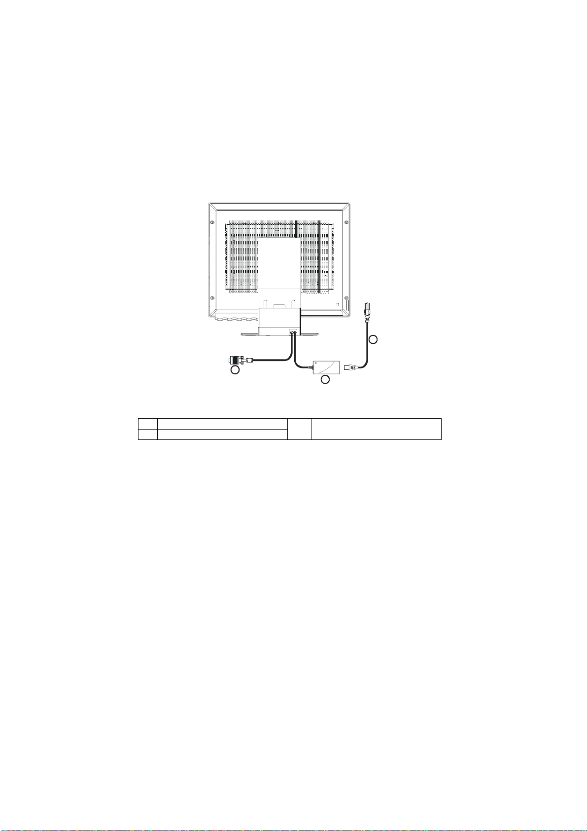
Figure 1 Connecting Cables
1. Signal Cable
2. External Power Adapter
VIDEO CABLE
Connecting the Signal Cable:
The LCD monitor comes with a built-in signal cable. Plug the signal cable′s
15-pin connector into the computer's video port and tighten the two screws on
the cable connector. Refer to Appendix for the detail connector pin
assignment.
3. AC Power Cord
1
Page 7
POWER CORD
Power Source:
1. This LCD monitor has a universal power adapter that allows operation in
either 100/120V AC or 220/240V AC voltage area (No user adjustment is
required.)
2. Connect the power cord into your LCD monitor’s power input socket, and
then plug the other end into a 3-pin AC power outlet.
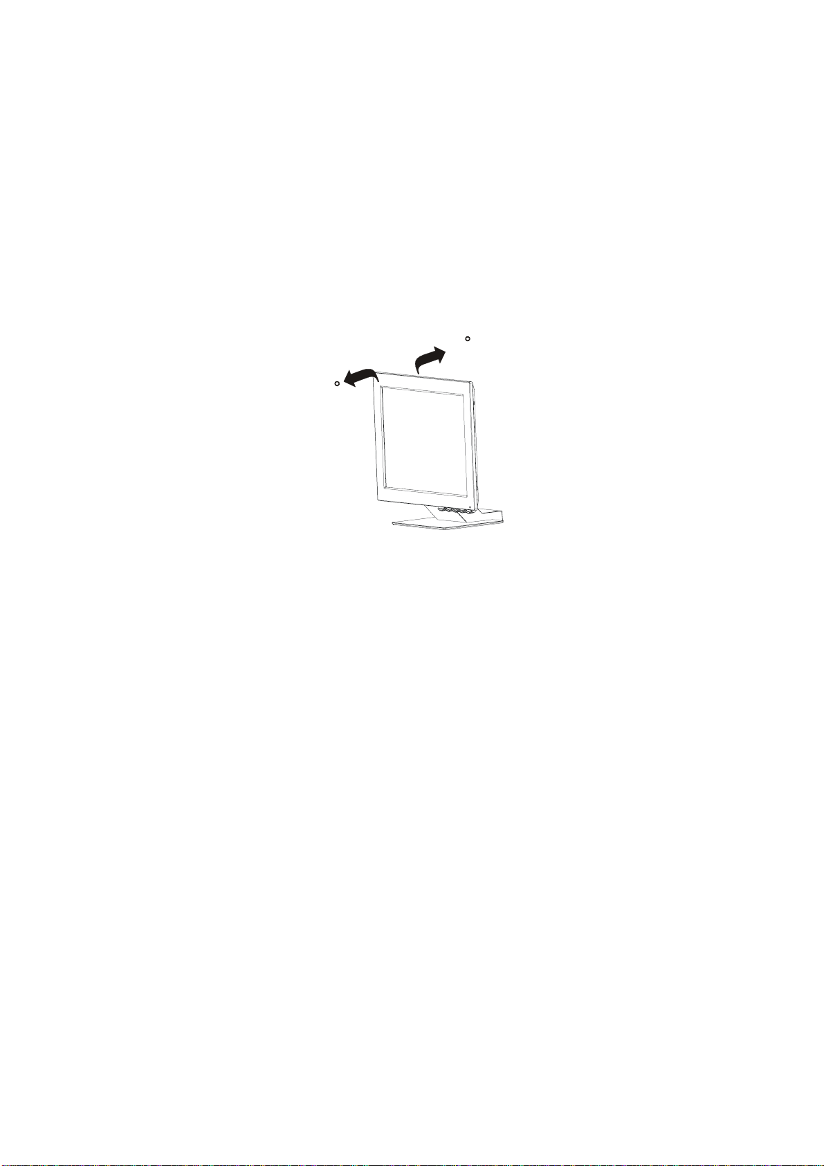
ADJUSTING THE VIEWING ANGLE
• For optimum viewing it is recommended to look at the full face of the
monitor, then adjust the monitor’s angle to your own preference.
• Hold the stand so you do not topple the monitor when you change the
monitor’s angle.
• You are able to adjust the monitor’s angle from -4° to 41°.
41
-4
Figure 2
NOTES
Be careful if you touch the LCD screen, you may damage it.
•
• Be careful. Do not catch your fingers or hands when you change the
angle.
2
Page 8

OPERATING INSTRUCTIONS
GENERAL INSTRUCTIONS
Press the power button to turn the monitor on or off. The other control buttons
are also located on front panel of the monitor (See Figure 3). By changing
these settings, the picture can be adjusted to your personal preferences.
• Press the power button to turn on the monitor. The power indicator will
light up.
6
5
4
3
2
1
CONTROLS
Figure 3 Control buttons
Icon Control Description
Displays the OSD main menu
1
Exit
Exits from menus and sub-menus
Exits the OSD
Displays the OSD main menu
2
Left Arrow
Moves the cursor to highlight icons and
other options
Displays the OSD main menu
3
Right Arrow
Moves the cursor to highlight icons and
other options
Displays the OSD main menu
4
OSD Enter
Enters menus and sub-menus and selects
the highlighted option
5
6 LED
Power Switch
Switches the monitor on and off
The LED indicator
3
Page 9

Operation
Press any OSD control buttons to display the main OSD menu.
Use the Arrow buttons to move among the icons. Select an icon and
press OSD Enter to access that function. There is a sub-menu for you to
move between options by using the Arrow buttons. Then press OSD
Enter to select that function. Use the Arrow buttons to make adjustments.
Press the Exit button to move backwards through the sub-menus and exit
from the OSD.
OSD Lock / Unlock:
This feature allows you to secure the current control settings, so that you
cannot inadvertently change these settings while you adjust Brightness and
Contrast. You can unlock the OSD controls through the same procedure.
Push and hold the OSD Enter button for 10 seconds to Lock or to Unlock.
When locked, a “LOCKED” message will be displayed.
HOW TO ADJUST A SETTING
The settings adjusted by the user controls are viewed through the On-Screen
Display (OSD). Press any OSD buttons to activate the OSD.
Initial appearance of OSD
OSD Message
4
Page 10

ADJUSTING THE PICTURE
OSD functions
OSD icon Description
Brightness
Adjusts brightness
Submenu(s)
Controls and
Adjustments
Contrast
IMAGE LOCK
IMAGE LOCK
(Continued)
IMAGE
POSITION
Adjusts contrast
This image lock function is used
to adjust the level of noise in the
video signal, which causes
horizontal lines or areas on the
screen where the image appears
to be unstable and jitters or
shimmers. This can be done
automatically or manually.
Use the Arrow buttons to adjust
away the interference. If
satisfactory results are not
obtained by using the Fine
adjustment first, then use the
COARSE adjustment and finally
use FINE adjustment again.
These actions may change the
width of the display image. Use
the H-Position function on the
image position menu to center
the display image on the screen.
Moves the screen left and right or
up and down.
Automatic Automatic adjustment
Manual
˙Fine
˙Coarse
H-position
V-position
5
Page 11

OSD functions
Select the Color Mode you find
most comfortable and then fine
COLOR
tune the color using the user
Color Mode menu, if necessary.
Color Mode
User Mode –
˙Red
Mode 1
(Cool White, 9300°K)
Mode 2
(Normal White, 7200°K)
Mode 3
(Warm White, 6500°K)
Increases or decreases
redness
RESET
INFORMATION
LANGUAGE
OSD MENU
POSITION
Resets the Brightness, Contrast
and Color settings.
Resets the image position
settings.
Shows information about the
addressability and the horizontal
and vertical frequencies of the
images received from the
computer
The language chosen affects
only the language of the OSD. It
has no effect on any software
running on the computer.
Changes the position of the OSD
on the screen.
˙Green
˙Blue
Color Reset
Geometry
Reset
H-Position
Increases or decreases
greenness
Increases or decreases
blueness
NO–Does not make the
adjustment
YES–Resets the color
NO– Does not make the
adjustment
YES–Resets the
geometry
Select one of the five
languages to use for the
OSD.
V-Position
6
Page 12

Device driver installation
Use the User’s Guide and Installation Files CD that comes with your
monitor to install the appropriate device driver for your operating
system.
Installing the Windows XP device driver
To manually install or update the device driver for the Microsoft®
Windows® XP operating system, perform the following steps:
1. Insert the User’s Guide and Installation Files CD into the computer
CD- ROM drive.
2. Click Start →→→→ Control Panel →→→→ Appearance & Themes and
then click the Display icon.
3. In the Display Properties window, click the Settings tab, and then
click Advanced.
4. Click the Monitor tab, and then click Properties →→→→ Driver tab →
Update Driver.
5. When the Hardware Update Wizard window opens, select “Install
the software automatically,” click Next> and then Finish to
complete the installation.
6. Close the Display Properties window.
7. Remove the User’s Guide and Installation Files CD from the
computer CD-ROM drive.
Installing the Windows Me device driver
To manually install or update the device driver for the Microsoft
Windows Millennium Edition operating system, perform the following
steps:
1. Click Start →→→→ Settings →→→→ Control Panel and then double-click
Display.
2. In the Display Properties window, click the Settings tab, and then
click Advanced.
3. Click the Monitor tab, and then click Change →→→→ Specify the
location of the driver →→→→ Next.
→
→→
7
Page 13

4. When the Update Device Driver Wizard window opens, select
"Display a list of all the drivers in a specific location, so you can
select the driver you want," and click Next>.
5. Insert the the Device driver and User’s Guide CD into the
computer CD- ROM drive, then click Have Disk.
6. Type d:\ (change the drive letter to match your CD-ROM drive if it
is not drive D) in the Copy manufacturer's files from: box, then
click OK.
7. Click Next>, Next>, and then Finish to complete the installation.
8. Close the Display Properties window.
9. Remove the User’s Guide and Installation Files CD from the
computer CD-ROM drive.
Installing the Windows 2000 device driver
To manually install or update the device driver for the Microsoft
Windows 2000 Professional operating system, perform the following
steps:
1. Click Start →→→→ Settings →→→→ Control Panel and then double-click
Display.
2. In the Display Properties window, click the Settings tab, and then
click Advanced.
3. Click the Monitor tab, and then click Properties →→→→ Driver →
Update Driver.
4. When the Update Device Driver Wizard window opens, select
"Search for a suitable driver for my device," and click Next>.
5. Insert the Device Driver and User’s Guide CD into the computer
CD-ROM drive, type d:\ (change the drive letter to match your CDROM drive if it is not drive D) in the Copy manufacturer's files
from: box, click Next> and then Finish to complete the installation.
6. Close the Display Properties window.
7. Remove the User’s Guide and Installation Files CD from the
computer CD-ROM drive.
→
→→
8
Page 14

Installing the Windows 98 device driver
Windows 98 automatically detects the new monitor and displays the
Add New Hardware Wizard dialog box if the device driver is not
already installed.
1. Insert the Device Driver and User’s Guide CD into the computer
CD-ROM drive, and click Next> twice when the Add New
Hardware Wizard window opens.
2. Click the CD-ROM drive box to install the device drivers from the
CD and then click Next>.
3. Confirm that the device driver was found on the CD, and click
Next> twice to install the device driver.
4. Click Finish to exit the Add New Hardware Wizard dialog box.
To manually install or update the device driver for the Microsoft
Windows 98 operating system, perform the following steps:
1. Click Start →→→→ Settings →→→→ Control Panel and then double-click
Display.
2. In the Display Properties window, click the Settings tab, and then
click Advanced.
3. Click the Monitor tab, and then click Change.
4. When the Update Device Driver Wizard window opens, follow the
steps in the previous paragraph.
5. Remove the User’s Guide and Installation Files CD from the
computer CD-ROM drive.
Installing the Windows 95 device driver
Right-click the My computer icon on the computer desktop and then
select Properties →→→→ System to view the version number listed in the
System window. Perform the steps below for the appropriate version.
If you have Windows 95 Version 4.00.950A, use the following steps to
manually install or update the device driver:
1. Click Start →→→→ Settings →→→→ Control Panel and then double-click
Display.
9
Page 15

2. In the Display Properties window, click the Settings tab and then
click Change Display Type.
3. In the Change Display Type window, click Change and then click
Have Disk.
4. Insert the Device Driver and User’s Guide CD into the computer
CD-ROM drive, type d:\ (change the drive letter to match your CDROM drive if it is not drive D) in the Copy manufacturer's files
from: box, and click OK.
5. In the Select Device window, click the appropriate monitor model
and then click OK.
6. In the Change Display Type window, click Close.
7. In the Display Properties window, click OK.
8. Remove the User’s Guide and Installation Files CD from the
computer CD-ROM drive.
If you have Windows 95 Version 4.00.950B, use the following steps to
manually install or update the device driver:
1. Click Start →→→→ Settings →→→→ Control Panel and then double-click
Display.
2. In the Display Properties window, click the Settings tab and then
click Advanced Properties.
3. In the Advanced Display Properties window, click the Monitor tab
and then click Change.
4. In the Select Device window, click Have Disk.
5. Insert the Device Driver and User’s Guide CD into the computer
CD-ROM drive, type d:\ (change the drive letter to match your CDROM drive if it is not drive D) in the Copy manufacturer's files
from: box, and click OK.
6. In the Select Device window, click the appropriate monitor model
and then click OK.
7. In the Advanced Display Properties window, click Close.
8. In the Display Properties window, click OK.
9. Remove the User’s Guide and Installation Files CD from the
computer CD-ROM drive.
10
Page 16

TECHNICAL SUPPORT (FAQ)
TROUBLESHOOTING
Problem
Screen is blank
and power
indicator is off
Screen is blank
and power
indicator is
steady green
Screen is blank
and power
indicator is
steady amber
Screen is blank
and power
indicator is
flashing green
every 0.5
second
Possible
Cause
No Power to
monitor
Brightness
and Contrast
may be too
low
The monitor is
in the Power
Management
Standby state
Display mode
of the
computer is
outside the
range of the
monitor
Suggested Action Reference
Ensure that the electrical
outlet and the monitor are
both switched on.
Check that the power cord
is firmly plugged into the
electrical outlet and the
power supply unit.
Try another power cord.
Try another electrical
outlet.
Adjust brightness and
contrast.
Press any key on the
keyboard or move the
mouse to restore
operation.
Check the Power
Management software on
your computer
Reconfigure the computer
to use a supported display
mode.
CONTROLS AND
CONNECTORS
Section on page 1
OPERATING
INSTRUCTIONS
Section on page 3
Power Management
section on page 16
Factory set display
mode
Section on page 15
11
Page 17

Problem
Screen is blank
and power
indicator is
flashing amber
every 0.5 or 1
second
Screen is blank
and power
indicator is
flashing green
every 1 second
Image appears
to be smeared
Image appears
to be discolored
Possible
Cause
The monitor is
in the Power
Management
Suspend or
Off state
The monitor is
not receiving
a video signal
The Color
setting may
be incorrect
Suggested Action Reference
Check the Power
Management software on
your computer
Power Management
section on page 16
Check that the signal
cable is firmly connected
to the computer.
Check that no pins are
bent in the signal cable
CONTROLS AND
CONNECTORS
Section on page 1
connector.
Select IMAGE LOCK
menu in the OSD. Then
select MANUAL to adjust
FINE/COARSE settings.
Adjust the Color settings.
OPERATING
INSTRUCTIONS
Section on page 3
OPERATING
INSTRUCTIONS
Section on page 3
The LCD contains over
2,300,000 thin film
A few dots are
missing,
discolored, or
inappropriately
lighted.
transistors (TFTs). A small
number of missing,
discolored, or lighted dots
may be present on the
screen, which is an
intrinsic characteristic of
the TFT LCD technology
and is not an LCD defect.
“COARSE” (pixel frequency) controls the number of pixels scanned by one
horizontal sweep. If the frequency is not correct, the screen shows vertical
stripes and the picture does not have the correct width.
“FINE” adjust the phase of the pixel clock signal. With a wrong phase
adjustment the picture has horizontal disturbances in light picture.
For “FINE” and “COARSE” adjustment use a dot pattern or Windows 95/98
/ME/XP/2000 shutdown screen.
12
Page 18

APPENDIX
SPECIFICATIONS
IBM 9512-AW*/ AB* TFT Color LCD Monitor
Driving system TFT Color LCD
LCD Panel Size 381mm(15.0")
Pixel pitch 0.297mm(H) x 0.297mm(V)
Viewable angle
120° (H) 100° (V)
Response time 30 ms
Video R, G, B Analog Interface
Input Separate Sync. H/V TTL
H-Frequency 30kHz – 60kHz
V-Frequency 55Hz-75Hz
Display Colors 16.7 million Colors
Dot Clock 80MHz
Max. Resolution 1024 x 768
Plug & Play VESA EDDC
EPA ENERGY STAR®
ON Mode <
30W
Active OFF <3W
OFF Mode <1W at 100Vac
<2W at 220Vac
Input Connector D-Sub 15pin
Input Video Signal Analog:0.7Vp-p 75 OHM,
Maximum Screen Size Horizontal: 304.1mm (12.0”)
Vertical: 228.1mm (9.0”)
Power Source 100~240VAC,50~60Hz
Environmental
Considerations
Operating Temp: 10°C to 35°C
5°F to 95°F
Ship/Storage Temp: -20° to 60°C
-4°F to 140°F
Operating Humidity: 10% to 80%
non-condensing
Ship/Storage Humidity:
5% to 95% non-condensing
Weight (N. W.)
unpackaged:
packaged:
Regulatory
Compliance
4.8kgs
6.2Kgs
UL, CSA, FCC, TÜV, CE,
TCO’99 for Pearl White models
TCO’95 for Stealth Black models
13
Page 19

CONNECTOR PIN ASSIGNMENT
15
6
11 15
10
15 - Pin Color Display Signal Cable
PIN NO.
DESCRIPTION
PIN NO.
DESCRIPTION
1. Red 9. +5V
2. Green 10. Detect Cable
3. Blue 11. Ground
4. Ground 12. DDC-Serial Data
5. Ground 13. H-Sync
6. R-Ground 14. V-Sync
7. G-Ground 15. DDC-Serial Clock
8. B-Ground
14
Page 20

FACTORY PRESET TIMING TABLE
DISPLAY MODES
The display mode the monitor uses is controlled by the computer. Therefore,
you should refer to your computer documentation for details in how to change
display modes.
The image size, position and shape may change when the display mode
changes. This is normal and the image can be readjusted using the monitor
controls.
Unlike CRT monitors, which require a high refresh rate to minimize flicker,
TFT technology is inherently flicker-free. If possible, configure your computer
for 1024 X 768 addressability at 60Hz vertical refresh rate.
For the display modes listed below, the screen image has been optimized
during manufacture.
Factory Set Display Modes
ADDRESSABILITY
640 × 350 70Hz 31.5kHz
640 × 480 60Hz 31.5kHz
640 × 480 72Hz 37.9kHz
640 × 480 75Hz 37.5kHz
REFRESH RATE
HORIZONTAL
FREQUENCY
640 × 480 67Hz 35.0kHz
720 × 400 70Hz 31.5kHz
800 × 600 75Hz 46.9kHz
800 × 600 72Hz 48.1kHz
800 × 600 60Hz 37.9kHz
800 × 600 56Hz 35.2kHz
832 × 624 75Hz 49.7kHz
1024 × 768+ 60Hz 48.4kHz
1024 × 768 70Hz 56.5kHz
1024 × 768 75Hz 60.0kHz
+ Recommended
15
Page 21

Power Management
As an E
E
NERGY STAR
NERGY STAR
The power management feature is invoked when the computer recognizes
that you have not used your mouse or keyboard for a user-definable period.
There are several states as described in the table below.
IBM recommends that you switch off your monitor at the end of each working
day, or whenever you expect to leave it unused for long periods during the
day.
®
®
Partner, IBM has determined that this product meets the
guidelines for energy efficiency.
State
Power
Indicator
Screen
Restoring
Operation
Compliance
On
Active Off
Off
Steady green Normal
Steady amber Blank
Steady amber Blank
Press a key or move
the mouse.
Press a key or move
the mouse.
The picture will be re-appeared few seconds later.
NERGY STAR
E
And NUTEK
E
NERGY STAR
And NUTEK
®
®
16
Page 22

Service Information
The following parts are for use by IBM service, or IBM authorized dealers, to
support customer warranty. Parts are for service use only.
Model Type 9512-AB*/9512-AW*
P/N Description Video Color MTM Geography
31P7251 FRU Monitor Analog SB 9512-AB1 WW
31P7252 FRU Monitor Analog PW 9512-AW1 WW
31P7253 FRU Stand Analog SB 9512-AB1 WW
31P7254 FRU Stand Analog PW 9512-AW1 WW
31P7255 FRU Power Supply Analog Black
31P7256 FRU Video Cable Analog Black
Note:
WW FRU Monitor includes Monitor, Stand, Power Supply & Video Cable.
9512-AW1
9512-AB1
9512AW1
9512-AB1
WW
WW
17
 Loading...