

Page 1

IBM
ELECTRIC TYPEWRITER
MODEL
CUSTOMER ENGINEERING
REFERENCE MANUAL
Mechanical Principles
CONTENTS
NelV JPeatures _________________________________ 3
Case
and
~otor
Keylevers,
Resilient
~aper.nent
Space
ldargin
!4argbl
Line
Carriage
Paper
I>ecelerator ___________________________________ 22
Tabulation
Backspace
-Carriage
Shut
Ribbon,
Ribbon,
Covers
and
])rive
Letter
Keyboard
Bar
_____________________________________
Reset
Release
Lock
_____________________________________
and
Feed
Return
_________________________________________
Carbon
Fabric
______________________________ 3
____
~__________________________
Cams,
___________________________________
Rails _____________________________ 18
____________________________________
___________________________________ 25
____________________________________ 30
Control
__________________________________ 15
________________________________ 16
and
Line
________________________________ 36
________________________________ 39
C-l
and
Adjustments
Type
Bars
____________ 7
____________________ 10
Space
_______________ 31
P"g.
34
•
11
13
17
21
:INTERNATIONAL
NelV
Form
241-5002-0
BUSINESS
York
22, NelV
(this
MACHINES
York
section
only)
CORP.
/
Page 2

INTERNATIONAL
590
MADISON A VENUE.
Printed
© 1958
BUSu\ESS
NEW
In
U. S.
Form
241-5002-0
MACHINES CORP.·
YORK
22.
NEW
A.
1958
YOBK
(
I
Page 3
IBM ELECTRIC
STANDARD TYPEWRITER
MODEL
This
Model
above.
APPEARANCE.
been
tional
DECELERATOR.
quiets
riage
operate
RESILIENT KEYBOARD CONTROL.
pos~tions
mits
individual
SHIFT.
operation
MARGIN RESET.
been
malfunction
PLATEN
enclosed
RIBBON
feed
provide
feeding.
RIBBON
bon
typewriter
easier
CARRIAGE.
in
section
C1
completely
and
the
return
during
the
The
made
within
mechanism
cleaner,
mechanism
threading
13, 17, 20, 24
describes
typewriter,
The
case
redesigned
aesthetic
carriage
by
spring
operator
requirements.
and
easier
eliminated.
RATCHET.
MECHANISM-FABRIC.
MECHANISM-CARBON.
case
enabling
either
fingers
to
shift
the
the
has
faster
is
and
and
The
and
The
action
mechanism
adjustments
The
to
completely
Model C
improvements.
operation.
set
operate
left-hand
been
has
more
30
C-l
the
serial
numbers
and
to
decelerator
during
the
centrifugal
under
the
the
touch
margin
and
The
platen
carriage-end
completely
ribbon
been
accurate
inch
changing,
typewriter
carriage
new
features
cover
include
tabulation
key
to
has
been
simplified.
reset
the
ratchet
7he
The
contained
improved
feeding.
of
1,100,000
sections
many
improves
and
governor
This
levers
suit his
mechanism
lengths.
control
and
or
improved
possibility
has
cover.
fabric
and
carbon
within
to
is
available
ribbon
positive
provide
redesigned
the
and
have
func-
and
car-
to
per-
her
in
has
of
been
to
rib-
the
CASE AND COVER SECTIONS
The
typewriter
tion
or
case
and
Bristo
Four
shell. A
is
down
corner
in
the
are
rubber
with
screws
tom
section
latched
front
Lugs
Carriage-end
tons
by
rear
two
hinged
over
of
bottom
covers
secured
mounts,
is
contained
cover-section
long
to
the
the
the
keyplate
bottom
case-section
contain
over
inside
of
in a bottom
screws.
bottom
case-section
anchor
the
carriage-release
each
the
end
screwed
3
mounts
The
front
case-section
by a latch
the
end
of
the
covers.
to
the
case-sec-
to
the
bot-
cover-
and
at
each
(Figure
typewriter
1).
keyplate.
but-
carriage
Page 4

MODEl
CI
CUSTOMER ENGINEERING
side frames
through
mcunts. This gives
ing when in
desk
and
ing.
A locking
chors
the
desk. By sliding
machine
removed from
A removable bottom
case section
This
panel
ments
working
the
typewriter
the
typewriter
may
and
may also
on
set
into
bottom case
its
case
bar
be
the
and
can
be
the
machine.
the
bottom case. Base feet pass
and
the
typewriter
and
when
inside
to two desk mounts, secured to
the
quickly
desk.
panel
serves
easily removed
be
used
screw into
provides protection
it
the
locking
and
to
a resilient mount-
is removed
bottom case-section
easily attached to
slides into
protect
to
protect
bar
the
to
make
the
the
for
laterally
the
typewriter.
desk
r~
I .. '
rubber
to
the
servic-
anthe
bottom-
adjuat-
whell
.'
...
---
or
Figll"
1.
CdS'
"nil
COfl81'
Meeh""isfIJ
Removal
CASE
aDeI
COVERS
1.
Release
2.
Remove
mounting screws. (
3.
Disconnect
sembly,
the
C clips
the
front cover.
the
the
on
each side
and
front
rear
the
hinges from
pushing
cover-latch
cover by removing
of
in
the
on
4
••
the
ann
machine,
the
arms,
and
shatt
by
remcwinl
and
its
w..
u-
remove
Page 5
REFERENCE
4.
Remove
MANUAL
the
mounting-brackets
keyplate.
5. Disconnect
separating
6.
Turn
base
feet,
free
of
the
CARRIAGE
roll-release,
two
end-cover
TOP
PAPER
the
the
male
the
machine
and
allow
base section.
END
or
detent-release
mounting-screws.
TABLE.
ward.
CASE
and
1.
KEYPLATE.
COVERS
mounting-brackets
front
case-section smoothly.
operate
2.
tion
section
The
freely
HINGES.
when
the
to
clear
front
case
without
Adjust
latches
shall
raiserl position .
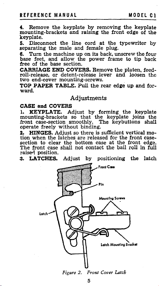
.3. LATCHES.
keyplate
and
line
and
up
the
by
raising
cord
female
on
its back.
power
removing
the
at
COVERS. Remove
lever
Pull
the
rear
Adjustments
Adjust
the
Adjust
so
that
binding.
so
there
are
bottom
not
by
forming
the
The
is sufficient
released
case
contact
by
positioning
the
front
the
typewriter
plug.
unscrew
frame
the
platen.
and
edie
the
keyplate
keybuttons
for
the
at
the
the
bail
MODEl
keyplate
edge
of
the
to
tip
loosen
up
and
keyplate
joins
vertical
front
front
roll
in
the
Cl
the
by
four
back
feed-
the
for-
the
shall
mo-
case-
edge.
full
latch
Latch
Figure 2. Front Cover Latch
5
Page 6

MODEl
Cl
CUSTOMER
ENGINEERING
mounting
the
~2"-O.
the
(Figure
4.
ance
of
%2"
The
main
bracket
front-case-section
There
front
and
2).
PLATEN
between
to
3i14".
motor, drive,
essentially
B machine.
simplify
removal
conform to
The
motor
space for
The
the
to
simplify
ring
left
rear-rail
mount
mounting
so
that
the
latches
pin
by
shall
be a maximum
bottom
KNOBS.
the
left
case-sections
Adjust
and
stock
to
right
MOTOR AND DRIVE
and
the
Changes
the
new
is a
is
motor
and
new
the
has
removal
electrical
same
in
operation
have
been
adjustment
case design.
3" design
mechanisms
same
as
been
placed on
procedures
and
the
bottom
thickness
of
when
have
carriage-end
~"
equal
against
plus
between
latched
clear-
covers
mechanisms
as
the
in
allow
save
Model
design
and
more
weight.
made
procedures,
used
to
to
Model B; however,
the
rear
(Figure
frame
3).
re-
to
to
CAUTION:
motor,
LINE
The
drive,
CORD
line
cord
SwItch
IndIcator
Figul'e 3. Motol' and Dl'ive
Removal
Unplug
and
is
machine
when
electrical components.
removable
by
means
6
servicing
the-
of a pluggable
(
Page 7

REFERENCE
unit
attached
slot
low
CAUTION:
installing,
MANUAL MODEl
to
the
rear
in
the
Plug
to
prevent
rear
must
frame. Access
portion
be
properly
of
possible shock
MOTOR
1.
Remove complete case
2. Remove
screw
3. Disconnect
lever
4.
Remove
rear
frame
and
rear
from
spring,
frame.
the
the
to
and
the
the
belts
left
the
the
six
side-frame.
side frames,
and
and
the
tab-lever
tab-set
mounting
and
SWITCH
The
switch
frame
disconnecting
by
removing
may
the
be
removed
the
rear
switch
cover,
wiring.
POWER ROLL
1.
Remove complete case
2.
Refer
to
Model
The
lower
Note:
longer
ribbon
and
mechanism.
power-roll-bearing-retainer
serves
BI,
also as a
and
Power
Adjustments
1.
SWITCH.
Adjustment
2.
BEARINGS.
Adjustment
3. POWER ROLL END PLAY.
Motor
and
4. DRIVEN BELT.
Drive,
5.
tor
6.
Drive,
Adjustment
POWER ROLL SPEED.
and
DRIVE BELT.
Adjustment
7. MOTOR MOUNTINGS.
justed
without
bottom
screws
and
Refer
1.
Refer
2.
Drive,
Drive,
Adjustment
Adjustment
removing
case-section
repositioning
to
Refer
4.
Refer
6.
Model
to
Model
by
the
to
Refer
5.
to
Belt
the
loosening
motor.
the
bottom
seated,
hazard.
cover sections.
is
belt
tension
spring,
and
tab-clear
studs
remove
from
the
the
switch
cover
tab-actuating-
links.
that
right
sections.
Roll Removal.
spring
BI,
BI,
anchor
Motor
Motor
Refer
and
to
and
Model
3.
Model
Model
BI.
to
Model
BI.
tension
Motor
Motor
may
typewriter
the
Cl
through
case.
when
re-
adjusting-
hold
the
the
motor
side-
nut,
and
screw
for
the
Drive.
Drive.
BI,
and
BI,
Mo-
and
be
ad-
from
the
mounting
a
is
KEYLEVERS,C~S,TYPEBARS
The
keylever, cam.
Model C
is
B. However,
theoretically
the
and
typebar
the
same
keylevers, cams,
'I
operation
as
and
trip
on
the
levers
of
the
Model
have,
Page 8

MODEl
been
ration.
previous
underscore
provided
either
lever-bearing
crum
ing
frames
keylever
slightly
An
86
The
rod
support.
Cl
These
model
or
as
position
keylevers
held
and
to
'ij
redesigned
parts
typewriters.
88
character
is
the
only
standard
39
or
are
support
by
formed
The
assembly
is
adjustable
trip
lever
CUSTOMER ENGINEERING
in
order
to
are
not
keyboard
repeat/non-repeat
equipment
41.
mounted
and
fulcrum
lugs
in
clearance
improve
interchangeable
is
available.
and
is
available
in a redesigned
on a heavier
in
the
is
order
keylever-bear-
mounted
to
(Figure
to
obtain
4).
letter
their
the
proper
o~
with
The
key
in
key-
ful-
side
\-CIiP
PiK,,'e
4.
Keylefler Bearing
Each
row
of
spring. color coded for easy identification,
uniform
so
shift
sition.
the
guide-comb
available
. only.
been
with
touch.
that
all
are
Redesign
spring-loaded
Repeat/non-repeat
altered
a single piece
keylevers
The
functional
locked
of
the
to
be
for
carriage
by
replacing
when
repeat
plunger
redesigned.
keylever
has a different
keylever
and
letter
the
switch
letter
has
return,
letter
the
8
SII/Jpo,t
locking
containing
bar
keylevers
is
in
keylever
caused
Plunger
tab,
and
key
spring-loaded
operation
restoring
to
provide
is designed
except
the
OFF
to
eliminate
the
key
positions
an
lever
backspace
plunger
elongated
the
po-
are
has
Page 9

.£FERENCE MANUAL
MODEl
Cl
fulcrum-rod
keylever
(Figure
operation
the
the
places
erating
If
sired
keylever
The
operation
and a spring
5). .
takes
resistance
fulcrum
the
repeat
position.
Figlln 5.
additional
a two-piece
position.
letter
and
models.
KEYLEVEBS
1.
Remove
2.
Remove
3.
Disconnect
4. Remove
mounting
5.
6.
the
7.
lever
8.
and
keylever
9.
studs.
Disconnect
Insert
desired
a follow-up
keylever.
Remove
guide-comb
Lower
push
the
it
clears
Remove
hole. A
spring
is connected
bracket
As
the
keylever
place. As
of
the
point
upper
of
the
step
of
Rq,_/Non·Rej1UI
more
spring
keylever
the
trip-lever
is
repeat/non-repeat
cam
is
keylever
has
not
may
been
interchan~eable
reshaped
Removal
the
typewriter
the
resilient-keyboard-control
the
spacebar-switch-Iock shaft.
the
front
the
keylever
the
two
and
rear
the
of
the
the
guide-comb.
keylever
toward
from
frame
spring.
fulcrum
mounting
pivot
the
the
keylever
rear
of
by
9
by
the
pulling
above
the
keylever
depressed a single
between
pressure
is
applied
is overcome and
lowered.
lug
in
the
K~lwN
letter
cams
for
with
are
in
smoother
previous
section.
be
installed
the
base
indicator.
removing
rod
to
studs
guide-comb
between
machine
the
from
the
depth
the
forward.
the
cams
until
forward.
the
This
op-
de-
any
four
of
key-
the
Page 10
MODEL
Cl
CUSTOMER
ENGINEERING
LETTER
Refer
CAMS
to
Model
Bl,
Cam
Removal
Adjustments
1. CAM CLEARANCE
Bl
section.
2. KEYLEVER
sitioning
keylevers
plus
, guide-comb
or
the
trip
minus
(Figure
key
the
;.64"
3. INDIVIDUAL KEYLEVERS. Raise
conform
screwdriver
NOTE: Do
hammer
will
to
as
result.
adjustment
or
compress lugs
not
form
damage
•.
015"
BEARING
lever-bearing
cams
when
from
the
4).
2.
Spread
keylevers
to
the
to
.020".
SUPPORT.
support
the
bottom
key
with
pliers.
with
keylever-bearing
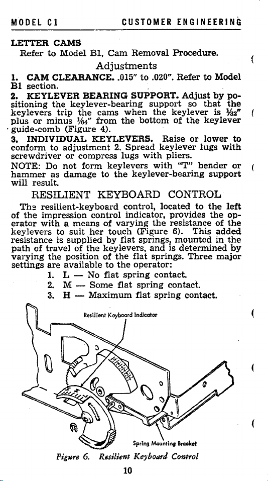
RESILIENT KEYBOARD CONTROL
The
resilient-keyboard
of
the
impression
erator
with a means
keylevers
resistance
path
of
varying
settings
travel
are
1. L - No
2.
3.
to
suit
is supplied
of
the
position
available
M -
H -
control
her
the
Some
Maximum
control, located
indicator, provides
of
varying
touch
by
flat
keylevers,
of
the
to
the
flat
flat
(Figure
springs,
flat
operator:
spring
spring
flat
the
and
springs.
contact.
spring
resistance
is
contact.
Procedure.
Refer
to
Adjust
so
that
keylever
of
the
key
or
lower
lever
lugs
"T"
bender
support
to
the
the
6).
This
mounted
determined
Three
contact.
Model
by
po-
the
is
¥.!2'"
lever
to
with
or
left
op-
of
the
added
in
the
by
major
Figure
6.
Resilient Keyboard Control
10
Page 11
REFERENCE
1.
Remove
2.
Remove
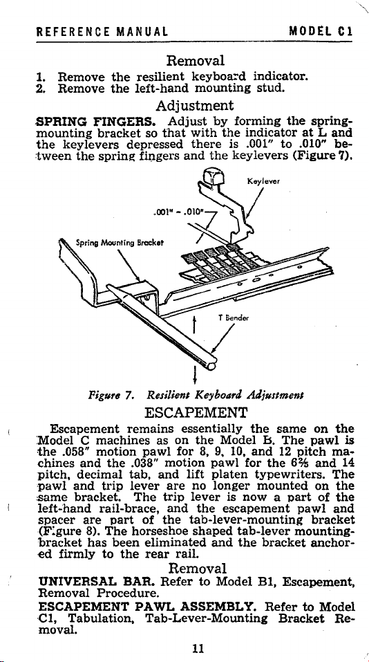
SPRING
mounting
the
key
:tween
the
FINGERS.
bracket
levers
the
spring
Figure
Escapement
Model C
the
chines
pitch,
'pawl
same
left-hand
spacer
(F:gure
bracket
ed
UNIVERSAL
Removal
ESCAPEMENT
Cl,
machines
.058"
motion
and
the
decimal
and
trip
bracket.
rail-brace,
are
8).
The
has
firmly
to
Procedure.
Tabulation,
part
moval.
MANUAL
Removal
the
resilient
left-hand
keyboa=d
mounting
Adjustment
Adjust
so
that
depressed
fingers
7.
Resilient Keyboard Adjustment
with
there
and
by
the
the
ESCAPEMENT
remains
.038"
tab,
lever
The
horseshoe
been
the
essentially
as
on
pawl
for
motion
and
lift
are
trip
lever
and
of
the
tab-lever-mounting
eliminated
rear
rail.
the
Model B.
8, 9, 10,
pawl
platen
no
longer
the
escapement
shaped
and
Removal
BAR.
Refer
to
Model
PAWL
ASSEMBLY.
Tab-Lever-Mounting
11
indicator.
stud.
forming
indicator
is .001"
keylevers
the
and
for
the
typewriters.
mounted
is
now a part
tab-lever
the
bracket
Bl,
Refer
MODEl
the
spring-
at
Land
H
to
.010
be-
(Figure
same
on
pawl
pitch
and
the
ma-
The
12
6%
The
on
the
of
the
pawl
and
bracket
mounting-
anchor-
Escapement,
to
Model
Bracket
Re-
Cl
7).
is
14
Page 12

MODEl
I.
be
injury
riage
drum.
follQwing
Cl
MAIHSPRING.
exercised
resulting
Tension
tension-tape
This
steps:
A.
Position
tab
check-lever
stop
on
B.
Set
C.
Hold
and
latch
D.
Gently
tab-check
Figure
8.Escllpemenl Mech,,,,istn
Adjustments
when
is
adjusted
adjustment
the
the
the
CAUTION:
servicing
from a disengaged
on
the
carriage
is
right
end
last
tab-stop.
carriage
the tab
position
lever
and
CUSTOMER
by
placing
various
may
directly
of
to
lever
the
release
12
this
lugs
be
checked
so
opposite
the
rack.
prevent
out.
set
tab-stop
the
ENGINEERING
Extreme
assembly
mainspring.
the
loop
of
the
through
that
the
the
any
carriage.
care
must
to
avoid
of
the
mainspring
against
car-
the
tip
of
the
last
tab-
movement
the
Page 13

IE
FE R ENe E MAN
E.
The
sion
to
A push-pull scale
tension
a slow
tion
erator
13" Carriage --
in
the
and
to
the
range). Tension shall
U A l
main
unlatch
spring should have suflicient
the
tab.
may
following manner.
steady
extreme
21h
rate
right
lbs. +
from
be
used
to
measure carriage
Pull
the
extreme
position, (excluding decel-
be
as follows:
Jf.&
- 0 Ibs.
lbs. maximum.
17" Carriage --
Ibs. maximum.
H
20
Carriage
lbs. maximum.
J4" Carriage
21h
lbs. +
'14
-0
lbs.
.-
2%
-.
lbs.+
23,4
Ibs. +
Jf.&
- 0 lhs.
¥.&
- 0 Ibs.
Ibs. maximum.
80'" Carriage •• 3 Ibs; +
Ibs. maximum.
2. UNIVERSAL BAR. Refer
Adjustment
men!;
I.
ADJUSTING PLATE ON UNIVERSAL
Refer
to Model
4.
TRIP
LINK:. Refer to Model
Adjustment
2.
Bl,
4.
~
- 0 lbs.
to
Model
~apement.
Adjustment
Bl,
SPACEBAR
The
repeat
tion
release
Depression of
spacebar features a controlled
action.
has
link
The
been
connected directly
spacebar cam release-lever rota-
reversed
the
spacebar
to
permit
to
through
the
the
its
MODEl
tl
ten-
the
at
at
at
at
at
start
stan
start
start
Bl,
carriage
left
start:to
at
posi-
to
3%
to
31h
3%
to
a~
to
,,~
lI:seape-
BAR.
3-
Escapement,
repeat/non·
use
of
a longer
spacebar shaft.
non;nal
travel
PigNr.
Front Fr
...
e
9.
SplU.hllr MechfItJum
18
Page 14
MODEl
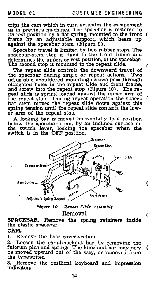
trips
as
its
frame
against
spacebar-stem
determines
The second stop is
the
adjustable-shouldered-mounting
elongated holes
and
peat
the
bar
spring
er
below
the
switch is
Cl
the
cam
position
by
an
the
spacebar
travel
which
by
adjustable support,
is limited
in
previous machines.
rest
Spacebar
stop is fixed
the
upper,
The
repeat
spacebar
slide controls
during
in
screw into
slide
repeat
stem
tension
arm
of
A locking
the
switch lever, locking
Spacobar Stam
the
is
spring
stop.
moves
until
the
repeat
bar
spacebar
in
the
During
the
is moved horizontally
OFF
CUSTOMER
in
turn
activates
The
a fiat spring,
stem
spacebar
(Figure
by
to
or
rest
mounted
single
the
repeat
loaded against
to
repeat
stop
position, of
the
or
slide
repeat
repeat
the
repeat
slide
slide contacts
stop.
stem,
by
an
the
position.
ENGINEERING
the
escapement
is
which
restored
to
the
bears
mounted
9).
two
rubber
the
the
repeat
downward
repeat
screws pass
(Figure
the
operation
down
stops.
front
frame
the
spacebar.
slide.
travel
actions. Two
front
10).
upper
through
The
and
the
against
the
to
a position
arm
inclined surface on
spacebar
when
to
front
up
The
and
of
frame,
re-
of
space-
this
low-
the
Figure
10. Repeat Slide Assembly
SPACEBAR. Remove
the
plastic spacebar.
CAM.
1.
Remove
2.
Loosen
fulcrum pins
be
moved
the
typewriter.
3.
Remove
indicators.
the
base cover-section.
the
cam-knockout
and
springs.
upward
the
out
resilient
Removal
the
spring
The
knockout
of
the
way,
keyboard
14
bar
retainers
by
removing
bar
or
removed
and
impression
may
inside
the
now
from
Page 15
REFERENCE MANUAL
4.
Remove
up
out
5.
D:Sconnect
lease link.
6.
Move
to
free
by
a C clip
the
left
of
the
the
its
the
cam.
side
impression-control
fulcrum
the
operating
operational
The
between
frame.
Adjustments
1.
CAM
clearance
screw
the
on
2.
when
rest
3.
ing, so
rest
4.
ing
bar
contact
s.
ment
reached.
be
CLEARANCE.
at
.010"
(Figure
power
the
CAM-RELEASE
SPRING-RETURN
position.
REPEAT
the
between
OPERATING
no
OFF.
rear
the
keylever
position.
the
spring
mounting
of
the
pawl
With
choking
9).
half
STOP.
the
repeat
just
the
to
Check
The
of
the
will
screws,
non-repeat
LINK.
before
cam
off.
has
slots.
cam
left
fulcrum
the
cam
Adjust
.015" using
by
release-lever
cam
lug.
LINK.
slide
Adjust
been
SUPPORT.
just
restore
Adjust
so
is
.015"
Adjust
the
high
on
its
shaft
link
and
fulcrum
rod
bearing
cam
the
releasing
so
depressed
Adjust
the
by
vertically
the
travel
tripping
to
.025"
to
point
high
point
MODEL
by
lifting
the
cam
rod
held
sUl}j)ort
to
power
the
should
the
cam
'is"
of
the
point
(Figure
the
of
the
there
enough
in
place
cam
with
trips
from
by
form-
to
position-
space-
and
escape-
cam
should
and
rest
is
adjustable-stop
lug
spacebar
trip
Cl
it
re-
roll
its
its
the
10).
is
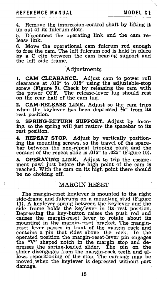
MARGIN RESET
The
margin-reset
side-frame
11). A
side
Depressing
causes
mounting
reset
contains a
operated
the
presses
slider
lows repositioning
moved,
damage.
and
keylever
frame
the
lever
"V"
the
disengages from
when
fulcrums
spring
holds
the
key-button
margin-reset
in
the
passes in
pin
that
position
shaped
spring-loaded
the
keylever
the
margin-reset
front
rides
the
margin-reset-Iever
notch
of
the
keylever
is
on a mounting
between
keylever
raises
lever
of
above
in
the
slider.
the
margin-rack
stop.
is
15
mounted
the
keylever
in
its
the
to
rotate
bracket.
the
margin
the
margin
The
The
carriage
depressed
to
stud
rest
push
about
The
rack.
pin
stop
pin
teeth
without
the
right
(Figure
and
the
position.
rod
and
margin-
nick
and
In
the
engages
and
de-
on
the
and
al-
may
part
its
be
Page 16
MODEL
C 1
CUSTOMER
ENGfNEERtIU
Adjustments
1. MARGIN·RESET LEVER.
clevi$ so
ance
the
margin
2. MARGIN-RESET BRACKET·ASSEMBLY. Posi-
tion
reset-lever
margin
a.
freely
that
with
of
.005"
reset-lever
stop.
left
or
right
pin
stoP.
MARGIN STOPS.
without
the
to
.015" between
pin
on
will
excessive
parts
and
the
rear
center
The
Adjust
at
rest
the
the
in
margin stops
play
bottom surface
top surface of
rail
so
the
"V" groove of
and
without
there
that
the
pusb-r04
is a clear-
the
margin-
shall
binding.
either
the
operate
of
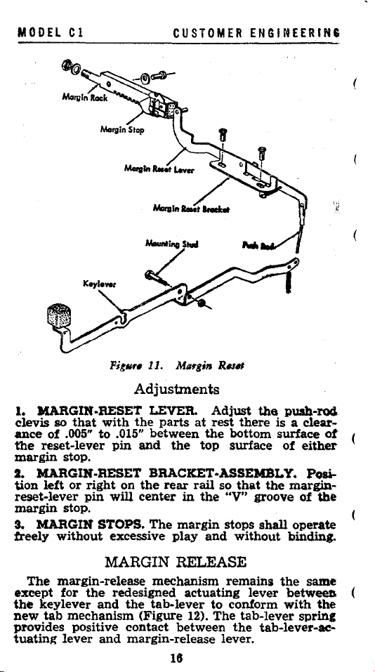
MARGIN RELEASE
The
margin-release mechanism remains
except for
the
keylever and
new
tab
provides positive contact between
tuating
the
redesigned actuating lever betwee!l
the
mechanism (Figure 12). The tab-lever spring
lever
and
tab·lever
margin-release lever.
to conform
18
the
tab-lever-ae-
the
with
same
the
Page 17
REFERENCE MANUAL
Acluating
Lev_er
__
Figure 12. Margin Release
Model
Bl,
the
typewriter
Refer
sary
to
to
remove
Pivot Stud
Tab
'1II~.a.
Removal
Margin
Release.
Lever
from
It
the
MODEL
is
not
base
Cl
neces-
section.
Adjustment
MARGIN RELEASE ECCENTRIC.
the
margin
margin
The
previous
conform
letter
tional
when
control
rack
by
line
lock
model
to
the
keylevers
and
letter
the
switch
lever
.010"
to
LINE
is
essentially
(Figure
new
rear
when
at
keylevers
is
in
the
clears
.015"
LOCK
13).
rail
the
except
OFF
17
the
(Figure
the
It
has
parts
right
the
position.
Adjust
underside
12).
same
been
and
to
margin.
shift
so
of
as
on
altered
lock
All
func-
are
locked.
that
the
the
to
all
Page 18

MODEL
Cl
PUSH ROD.
ment
2.
The
carriage
tion
and
changes
and
flexibility.
Model C
lengths:
tab-rack
anchors
margin
14).
lows
llny
operational
have
cover
13", 17", 20", 24"
center-support,
to
rack
It
mounts
the
operator
desired
CUSTOMER
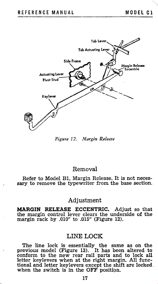
Figure 13. Line Lock
Adjustment
Refer
to
Model
Bl,
Line
CARRIAGE AND RAILS
has
been
section
carriages
the
carriage
where
into
location
retained
characteristics.
made
design
are
it
is
the tab
to
position
on
its
to
conform
and
available
and
on
carriages
and
bridges
attached
rack
any
length
18
box-frame
to
to
increase
in
30".
The
up
at
the
as
before.
either
carriage.
17"
margin
ENGINEERING.
Lock,
Adjust-
construc-
The
following
the
new
case
machine
the
following
margin
and
and
rear ( Figure
longer,
over
This
stop
and
the
al-
at
Page 19

REFERENCE MANUAL
Pigu,.11
14.
Ma,.gin
Platen
locking.
on
Pulling
lever
in
15).
latches
The
eccentrics, connected
the
over
the
latch
Platen latch Lever
have
new
latch
latch
the
toward
platen
lever, locking
been
consists
shaft.
Rack
altered
by
a fiat
the
The
the
Cente,.
to
of
two
platen-latch
front
latch
two
together(
MODEL
Suppo,.t
make
them
levers,
pivots
the
engages a
Cl
self-
pivoting
link.
latch
notch
Figure
Figure
15.
Platen
Latches
The
multi-copy lever, fe!=!d-roll-release lever,
able-line-space
lever,
and
the
19
detent-release
varilever
Page 20

MODEl
Cl
CUSTOMER ENGINEERING
operate
form
The
buttons
Rails.
same
been
new
truck
as before.
to
the
new
cover
carriage-release
contained
trucks.
as
on
eliminated.
starwheels.
the
Model B.
Due
insertion
THIRTEEN
INCH
CARRIAGE
SEVENTEEN
TWENTY
INCH
INCH
CARRIAGE
CARRiAGE
They
in
the
method
have
design.
levers
carriage-end
RAILS
and
The
to
the
new
is
been
,altered
are
operated
rollers
carriage
carriage
used
(Figure
:..-..
covers.
remain
final-stop
lengths
Position No. I
to
con-
through
the
has
16).
a·
Figure 16.
Carriage
Removal
CARRIAGE AND RAILS.
may
be
1. Disconnect
removed
two
decelerator-arm
together
the
left-hand
springs.
20
Truck Insertion
The
an
assembly
carriage
as
tab-lever
as
spring
and
follows:
and
rails.
the
Page 21

REFERENCE MANUAL MODEl
2.
Unhook
margin-reset
3.
Unhook
the
backspace
lmk.
the
pawl-release
operating-link
and
clutch-unlatching
and
links.
4.
Unhook
ment-trip
5.
Remove
6.
Disconnect
sion
tapes.
7.
Remove
off
the
CARRIAGE.
between
1.
Remove
2.
Remove
3.
Disconnect
s.on
tapes
4.
Remove
5.
Move
the
margin-control
plate
6.
Remove
INNER
moved
justments
Model
the
link.
the
the
the
carriage
The
the
rails
the
the
the
at
the
the
the
carriage
to
pass
over
the
CARRIAGE.
without
by
following
BI
section
line
lock
push-rod
ribbon
from
the
carriage-return
four
rail-mounting
and
rails
assembly.
carriage
as
follows:
rear
cover.
right-hand
may
carriage
carriage-return
carriage.
margin-reset-Iever
to
the
lever
extreme
allowing
it.
carriage
disturbing
of
by
The
the
the
Reference
moving
inner
the
procedure
and
corner
and
screws
be
and
assembly.
left
the
it
carriage
rails
Manual.
the
escape-
ribbon
guides.
carriage-ten-
and
removed
end-cover.
carriage
and
depress
carriage
to
the
left.
may
or
carriage
outlined
be
in
Adjustments
1.
RAILS.
Adjustments
2.
PLATEN
so
that
the
eccentric
15).
3.
PLATEN
the
latch
4.
PLATEN
Carriage.
5.
PLATEN
BI,
Carriage,
S.
RING
riage,
7.
FEED-ROLL
el
Bl,
The
as
on
have
been
vent
paper
Refer
to
1,
2,
and
LATCH
the
platen
is
in
the
LATCH
firmly
engages
CONTROL-YOKES.
Adjustment
RETAINING-PLATES.
Adjustment
AND CYLINDER.
Adjustment
Carriage,
4.
CENTER-SUPPORT.
Adjustment
PAPER
paper-feed
the
Model B.
added
mechanism
to
slippage
Model
3.
LEVER
held
firm
forward
half
ECCENTRIC.
the
2.
3.
Refer
5.
FEED
is
An
additional
the
13"
on
and
these
BI,
Rail
Adjustments,
ECCENTRIC.
with
the
high
of
its
orbit.
Adjust
platen
latch
Refer
to
Refer
to
Model
Refer
the
same
set
17"
new
of feed
carriages
carriage
Adjust
point
(Figure
so
lever.
ModelBI,
to
Model
BI,
to
in
principle
to
lengths.
21
Cl
the
lift
from
ten~
end-
readthe
of
that
Car-
Mod-
rolls
pre-
Page 22

MODEL
Cl
CUSTOMER
ENGINEERING
FEED
FRONT
Model
Refer
ROLLS.
AND
Bl
to
Refer
REAR
section.
Model
Bl
DECELERATOR
The
centrifugal-governor.
clutches
centrifugal-governor
governor
the
tab
horseshoe
moves
spring
gear
governor
carriage, a spring
drum
assembly
utilizes a coiled
When
decelerator
and
cam
action
speed
of
rebound
The
assembly,
A
spring
the
check-lever,
shaped
centrifugal-governor
to
the
and
to
turned
left
drum
shaft.
rewind
andlor
clutch
which
in
arms
absorbs
moving
tab-lever
during
unwind
During
clutch
without
operating
is a
spring
one
Removal
to
Model
Bl
PRESSURE-LEVERS.
section.
Adjustment
section.
is a
control
It
consists
that
(Figure
carriage
carriage.
drives
left
allows
rotating
ratchet
fitted
direction
mechanism
of
17).
shock
air
rotate
the
pinion
to
right
the
the
governor.
like
closely
the
a series
the
The
It
cylinder
as
mainspring
mechanism
spring
control
the
mounting-bracket.
operates
tabulation.
they
the
Refer
to
for
the
of
spring
action
of
controls
the
and
carriage
main-
hub
and
on
the
of
and
and
gear
which
tightens
the
the
the
decelerator-
and
eliminates
the
As
the
the
gear
motion
hub
about a shaft.
Figure
(
17. Decelerator
22
Page 23

REFERENCE
about
the
turned
and
slips
CARRIAGE
During
up
the
causing
rotate
ure
18).
forces
tightening
hub
assembly.
pinion
creases
carriage
MANUAL
shaft
in
margin-control
the
the
the
gear
carriage
return
and
the
opposite direction
about
the
RETURN DECELERATION
carriage
margin-control
carriage-return-decelerator
The
carriage-return-decelerator-bellcrank
carriage-return-decelerator
its
spring
The
of
the
speed
operation.
+- Ccrrl"9$ Motion
Carriage
~rBellcrank
causes
shaft.
return
gear
Return
the
shaft
the
the
lever
clutch,
centrifugal-governor
during
left-margin-stop
and
moves
bellcrank
and
and
rotating
hub
the
assembly
last
MODEL
to
rotate.
spring
it
to
the
to
operate
bellcrank
arm
to rotate,
the
gear
drives
which
portion
Cl
When
relaxes
picks
right,
and
(Fig-
and
the
de-
of
the
Corrlage
Return
Decelerator
TABULATION DECELERATION
As
the tab
to
the
will
permit,
arm
spring. As a
lever
and
link
causes
Am
Figure 18. Carriage Return Deceleration
lever
right, as
under
moves
the tab
latches
far
set
it
the
as its
tension of
tab-stop
to
the
decelerator-bellcrank
tab
elongated
contacts
left,
23
the
check-lever
mounting-slots
tab-decelerator-
the tab
the tab
decelerator-
check-
to
moves
rotate
Page 24

MODEL
and
This
an
trifugal-governor.
carriage
absorbs
Cl
operate
action
increased
during
the
o
the
tightens
rotation
shock.
tab
decelerator-arm
the
tab
to
This
the
Tob
increased
last
portion
\
T
ob
Decelerator
Decelerator Bellerank
CUSTOMER ENGINEERING
spring-clutch
the
already
of a tabulation
Carriage Motion
Link
(Figure
operating
rotation
T
ob
Check
and
slows
Lever
19).
gives
cen-
the
and
The
decelerator,
spring
following
1.
2.
spring
wind
drum
Remove
Disconnect
drum.
slowly.
Figure 19. Tabulation Deceleration
Removal
gear
and
hub
may
these
steps:
typewriter
the
CAUTION:
be
removed
from
carriage-tension
24
assembly,
as a complete
the
base
Allow
tape
mainspring
and
section.
at
the
main-
unit
main-
to
by
un-
Page 25

REFERENCE MANUAL
3.
Loosen
sufficiently
4.
Unhook
tab
decelerator-arms.
5.
Remove
6.
Unscrew
shaft.
the
centrifugal-governor
to
prevent
the
springs
the
rear
the
spring-clutch
Adjustments
1.
SPRING
and
carriage-return
positioned
tor
arms
play
of
SPRING-CLUTCH
2.
the
end
tates
freely
- CLUTCH COLLARS.
on
the
rotate
arms
so
with
shaft
freely
on
that
end
to
the
collar
TABULATION
Tabulation
to
incorporate
on
the
the
stripping
to
the
frame.
spring-clutch
so
without
the
shaft
SHAFT.
the
play
Model C
advantages
decelerator-mounting
as
to
(Figure
Adjust
hub
and
not
to
has
MODEl
mounting-screws
gear
teeth.
carriage-return
The
their
17).
by
assembly
been
the
tabulation
should
decelera.003"
positioning
.003".
redesigned
decelerator
collars
allow
exceeding
gear
exceed
of
\
Cl
and
be
end
ro-
Figure
20. Tabukltion
25
Page 26

MODEL
Cl
C U S
TOM
E R
EN
GI
NEE
R I N G
(Figure
Model C
space
with
set
second
all
adjustable
tension
lever
tab
tab
other
The
lever
20). One
Typewriters.
on
standard
the
operation.
stop
on
tab
stoP.
standard
tab
latch
eccentric
of
the
works
against a lug
unlatching.
tab
pitch
the
when
pitches.
is
mounted
tab
lever
Tab
machines
Tabulation
6%
pitch
consecutive stops
and
works
lever
(Figure
Removal
TAB
LEVER
1.
Remove
It
is
ever,
cedure
2.
Remove
3.
Remove
4.
Disconnect
and
the
5.
Remove
6.
Remove
the
rear.
Reassembly
above
ing
nut
binding
TAB
1.
Remove
2. Remove
3. Disconnect
4.
Disconnect
pawl
5.
Remove
6.
Remove
7.
Block
the
tab-lever
8.
Remove
mounting-bracket
bracket.
Replacement
the
above
spacer
Care
,must
ing.screws
reassembly
bellcrank
the
paper
not
necessary
it
may
aid
to
do so.
the
the
the
decelerator-bellcrank
the
the
procedure. Avoid
LEVER MOUNTING BRACKET
spring.
must
may
on
the
tab-lever-pivot
of
the tab
the
the
the tab
the
the
the
the
carriage
mounting-bracket
three
procedure.
be
in
also
be
as
their
may
and
intermediate-pawl-release
table
to
remove
the
removal
margin
line-lock operating-lever.
tab-lever-pivot
tab
rear
carriage
margin-control
line-lock operating-lever.
may
tab-lever
lever
be
accomplished
lever.
cover.
tab-lever
screws
to
the
be
The
front
exercised
shoulder
result
rack.
over-tightening
from
operating
to
accomplished
of
in
assembly
stops
may
without
is possible
machine
atop
the
against a lower
<17).
on
the
tab
and
carriage
the
and
spring,
link.
stud.
by
lifting
stud
between
link.
spring
bellcrank.
prevent
is
that
secure
rear
rail
escapement
the
escapement
in
replacing
depths
binds
in
26
serves
be
set
interfering
and
are
rear
rail
The
tab-check
latch
end-covers.
rear
cover;
reassembly
tab-latch
it
up
and
by
reversing
the
as
movement
removed.
and
the
self-lock-
this
may
the
and
escapement
the
remove
by
pawl
and
trip-lever.
the
vary.
Improper
pawl-release
lever.
all
pitch
at
every
to
each
to
every
set,
on
with
an
ex-
to
effect
how-
pro-
spring,
toward
the
cause
rails.
when
tab-lever
the
reversing
pawl
mount-
(
Page 27

REFERENCE MANUAL
CAM
Refer
to
the
manual.
Spacebar
cam
removal,
Adjustments
1.
CAM CLEARANCE.
Adjustment
2. CAM RELEASE LINK.
is
tripped
to % of
3. MARGIN CO:ITROL LEVER
to
Model C1.
4.
TAB RACK.
justed
A.
LEFT
justed
.015" ± .002"
escapement
the
tab-check
(Figure
(1) Depress
tate
the
its
high
(2) Allow
set
tab
treme
Observe
(3)
faces
rack
tooth.
when
its
to
satisfy
TO RIGHT.
left
21).
power
point.
the
stop
left
position.
of
the
1.
downward
Margin
three
or
right
between
pawl
and
lever
the
tab
roll
carriage
positions
the
clearance
escapement
the
The
so
is
cam
by
Refer
keylever
Release,
an
Adjust
travel.
tab
rack
conditions.
The
tab
that
there
the
working
escapement
in
its
with
until
to
move
tab-check
between
pawl
the
hand
the
Carriage Motion
to
Adjustment
MODEL
in
this
section
Model
Cl,
Spacebar,
so
is
must
extreme
to
and
that
depressed
ECCENTRIC~
rack
is a
power
the
the
the
be
carefully
should
clearance
surfaces
rack
tooth
left
OFF
tab
cam
left
lever
working
the
escapement-
1.
so
to
Cl
of
the
cam
from
lh
Refer
ad-
be
ad-
of
of
the
when
position
and
ro;'
is
near
that
its
ex-
sur-
a
Escapement
B.
PARALLEL
of
the tab
the
rack
.015" :t .002"
~--
Figure 21. Tab Rack Adjustment,
rack
is
parallel
--;---If--
Pawl
=
TO
in
its
~
___
=/
RAILS.
elongated
to
the
carriage
27
_
Position
mounting
rails.
Tab Check
4A
the
This
....
right
slot
so
may
ena
that
be
Page 28

MODEl
Cl
CUSTOMER ENGINEERING
checked
an
C.
the
a
lever
NOTE:
rack
end-plates.
5.
mounting-stud
'h
the
tric
23).
by
equal
bite
PARALLEL
tab
rack
set
tab
stop
(Figure
Tob
Check
Figure 22. Tab
Caution
mounting-nuts
TAB
LATCH.
to % of
tab
must
the
lever
be
Tob
observing
that
the
on
all
set
TO
about
22).
Lever
is
kept
Check
TAB
its
parallel
must
be
so
Adjust
that
latched.
in
the
Lever
axis
as
the
surface
is
so
exposed
'~·"-"~-~i~~~
tab-check
tab
stops.
CHECK
so
that
to
the
RAck
Adjustment, 4C
used
in
not
to
by
positioning
tab-check
of a set
The
high
left
half
.-
tip
tightening
spring
of
-:::s.=
LEVER.
the
front
of
the
the
the
lever
tab
side
of
its
orbit
lever
takes
Position
face
tab-check
the
carriage
eccentric
engages
stop
when
the
eccen-
(Figtfre
of
tab-
Figure 23. Tab Latch Adjustment (
6. TAB-LATCH.
contact
when
full
with
the tab
left-hand
the tab
check-lever
position
Form
the
check-lever,
(Figure
28
tab-latch,
so
is .040"
24.)
Tob
Latch Eccentric
at
the
the tab
to
.045"
Set Tob Stop
point
unlatches
from
of
its
)
Page 29

REFERENCE MANUAL
MODEl
Cl
Carriage Motion
'1.
TAB
CHECK-LEVER
check-lever
there
is a
working
stop
the
of
keeper
26.)
when
keeper.
.003"
with
surfaces
to
Tab Check Lever
Figu1'e
Tab Lever
~4"
••
Figuf'e
24.
Tab Latch Adjustment
KEEPER.
keeper
clearance
the
front
.010"
the tab
on
the
rear
of
.010"
of
the
parts
are
rear,
lever
at
the
to
between
Tab Check Lever Keeper
25. Tab Check Level' Adjustment
to
tab
check-lever
rest
so
that
tab
latched
rail,
.025"
(Figure
there
check-lever
to
Position
left
to
between
and a tab
25).
is a
the
rear
the tab
right,
so
the
Position
clearance
and
the
(Figure
Figu1'e
26. Tab Check Leflef' Adjustm8nt
29
Page 30

MODEl CI
8.
OPERATING
so
there
contact
when
9.
high
.005"
lever
this
10.
right-lug
ment
11. DECELERATOR
this
carriage
19).
12.
B1,
13.
B1,
is a
surfaces
the
cam
Pigu,s 27. Ope,ating Link Adjustmsnt
TAB-LEVER
point
between
keeper
clearance
PAWL
so
rack
link
to
without
CENTRIFUGAL
Tabulation,
TAB
SET
Tabulation,
LINK.
clearance
of
is
on
EXTENSION.
there
should
the
overthrow
and
the
by
forming
RELEASE
the
escapement
by
.010"
obtain
interfering
Adjustment
AND
Adjustments
BACKSPACE
The
Model
Removal
backspace
Bl.
and
mechanism
Refer
to
Adjustment
CUSTOMER ENGINEERING-
Adjust
of .015"
the
tab
its
high
tab-lever
LEVER.
to
.020".
LINK.
the
maximum
GOVERNOR.
TAB
that
the
length
to
.020",
latch
and
point
(Figure
With
be a clearance
stop
the
pawl
with
lOa.
CLEAR.
11, 12,
is
section
procedures.
30
the
on
the
extension.
tab-lever
Form
clears
Adjust
cushioning
tabulation
Refer
Refer
13,
the
same
of
this
the
the tab
of
the
between
lever
27).
cam
on
of
.001"
tab
check-
Obtain
extension.
the
rear
the
escape-
length
of
(Figure
to
Model
to
Model
and
14.
as
on
manual
link
the
..
its
to
up-
of
the
(
the
for
Page 31

REFERENCE MANUAL
CARRIAGE RETURN
The
to
permit
The
clutch
more
positive
28).
Release
lever
forward
velop a
space
as
on
the
As
the
margin
carriage
and
stop
the
latch
of
the
pull
on
pawl
Model
carriage
picks
Pawl
return
decelerator
has
latching
carriage-return
causing
the
release
Bl.
approaches
up
Relea
..
mechanism
to
replace
been
modified
and
unlatching
cam
the
clutch
carriage-return
operations
the
the
margin-control
Bellcronlc
has
the
pulls
to
engage
tape.
remain
left
MODEl
been
air
to
provide
action
the
The
margin
lever.
Cl
modified
cylinder.
(Figure
clutch
and
de-
line-
the
same
the
This
a
Keylever
Figflfe 28. Carriagl1 Return
31
Can
Page 32

MODEL
pivots
three
1.
latching
the
2.
turn-tab
3.
ing
return-decelerator
section
Cl
the
margin-control
actions:
Allows
the
escapement
the
intermediate-pawl-release
pawl-release
Unlatches
the
interlock.
Cushions
the
the
centrifugal-governor
of
this
manual).
bellcrank.
clutch
shock
bellcrank.
Removal
Refer
to
Model
Bl
section.
Adjustments
1. CAM CLEARANCE.
bar,
Adjustment
2. CAM-RELEASE
is
released
to
full
peat
3.
there
normal
when
FRONT
is a
clearance
1.
LINK.
when
the
travel.
the
keylever
This
plunger
CLUTCH-LEVER
of
.010"
Clutch
CUSTOMER
bellcrank
pawl
by
rotating
of
carriage
through
(Refer
Refer
to
Adjust
is
will
has
allow
been
LINK.
to
.030"
Latch
Link
ENGINEERING
which
to
restore
lever
the
carriage-re-
return
the
to
Decelerator
Model
so
Cl.
that
depressed
the
cam
depressed
Adjust
between
performs
by
from
by
operat-
carriage-
Space-
the
from
to
n".
so
the
con-
un-
cam
%
re-
that
Front
Clutch
Lever
Link
Figure 29. Front Clutch Lever Link Adjultment
32
(
Page 33

REFERENCE MANUAL
tact
surfaces
when
the
4.
REAR
in
the
with
the
bellcrank
S.
CLUTCH
of
the
latch
bellcrank
riage-return-tab
6.
CLUTCH
so
the
of
the
the
carriage
1.
PAWL
riage
Return,
8.
MARGIN-CONTROL-BELLCRANK
tion
the
of
the
cam
is on
CLUTCH-LEVER
center
bellcrank
clutch
is
parallel
LATCH
hole of
unlatched
and
is
in
interlock
clutch
UNLATCHING
unlatches
carriage
by
RELEASE
travel.
hand
Adjustment
eccentric
clutch
its
to
LINK.
adjust
line
to
LINK.
stop
lever
high
the
bell-crank
the
the
rear
with
when
during
Latch
observe
16.
to
permit
point
LINK.
Place
so
Refer
and
(Figure
Position
elongated
rail.
in
the
slot
the
hole
the
clutch
LINK.
the
last
the
clutch
this
to
maximum
MODEL
the
clutch
29).
the
and
adjust
hole
the
center
in
the
in
is
Adjust
.100"
and
condition.
Model
Bl.
STOP.
Cl
latch
clevis
in
the
hole
clutch-
the
car-
latched.
the
link
to
.050"
return
Car-
Posi-
move-
so
Figure
30.
Carriage
Return Tab Interlock Ad;ustmtml
33
/
Page 34

MODEL
ment
with
9.
Form
lease
the
2
Cl
of
the
the
linelock
INTERMEDIATE
the
upright
lever
touches
pawl-release
spaces
from
margin-control
operating-lever.
bellcrank
the
CUSTOMER
PAW
lug
so
the
the
margin-control
when
left-hand
lever
10. CARRIAGE-RETURN-TAB
the
interlock
A.
Disconnect
B.
Wij;h
terlock
when
the
margin-control
ll.
CLUTCH
B1,
Carriage
COMPRESSION
12.
will
return
along
the
lever
to
the
so
it
left-hand
to
writing
th~
as
follows:
the
carriage
clears
bellcrank
PLATE
Return,
the
rear.
clutch
the
at
tab-lever
lug
of
unlatching
the
left
the
(Figure
CLEARANCE.
Adjustment
SPRING.
left
margin,
line,
with
L -
intermediate
margin.
interlock
Adjust
the
ENGINEERING
without
interfering
RELEASE
bellcrank
the
carriage
INTERLOCK.
link.
margin
lug
by
form
.005"
contacts
30).
Refer
to
18.
so
from
the
any
variable
linespace
LEVER.
pawl-re-
and
is 1
Adjust
the
in-
to
.015"
the
Model
carriage
position
13. MARGIN-CONTROL-LEVER DECELERATORSCREW.
rest
increase
14.
right
over
control
position
Adjust
with a minimum
the
decelerator
OVERBANK.
and
observe
an
escapement-rack
lever
is
from
31).
Left
Margin Stop
(Figure
the
screw
of shock.
Move
that
.010"
so
action
the
the
escapement
tooth
to
.015"
the
carriage
Lower
(Figure
carriage
when
from
comes
the
screw
18).
from
left
pawl
its
drops
margin-
full
the
Carriage Motion
to
to
right
I
to
to
The
ally
and
ance
adjustment
gle
assembly
binding
Figure 31. Overbank Adjustment
SHIFT
shift
mechanism
to
simplify
of
the
to
shaft
has
been
adjustment.
has
been
simplify
relocated
adjustment
assembly. Eccentric
34 ,
improved
The
equal
on
the
and
operation-
pin-clear-
shift
minimize
studs
tog-
mount
Page 35

REFERENCE MANUAL
the
segment
ing
"even
out
upsetting
PUSHER
1.
Remove
2.
Remove
retahe.t".
3.
IJisconnect
4.
Unhook
5.
l)isconnect
6.
Remove
levers
to
top
and
the
AND
the
the
the
the
assembly
the
type
bottom"
pin
Segment
.Mountlng
LEVERS
auxiliary
retainer
the
operating
shift-pusher
the
shift-pusher-Iever
shoulder
through
Adjustments
Rin~
and
fore
making
I.
CAM CLEARANCE.
Mechanism.
2. CAM
Mechanism.
3.
EVEN
Shift
NOTE:
used
to
used
4. MOTION.
Adjustment
cylinder
any
adjustments
Adjustment
RELEASE
Adjustment
TOP-AND-BOTTOM.
MechanisIll
The
adjust
to
insure
Adjustment
eccentric
for
even
that
Refer
2.
basket
clearance
fe_Ie
during
SeS!!lent
and
manufacture
(Figure
~-.
Removal
ASSEMBLY
hairpin-spring.
mounting-screws
link
at
link
at
screw
right
be
properly
to
Refer
Refer
1.
and
and
the
to
to
Refer
bottom.
is
BI,
the
must
3.
LINK.
4.
segment-mountings
top
the
segment
to
Model
MODEl
aid
in
establish-
32).
the
rear.
the
key
lever.
spring.
the
pusher-and-
side-frame.
adjusted
shift
mechanism.
Model
Model
to
BI,
BI,
Model
Care
not
tilted.
Shift
Mechanism,
with-
and
may
must
Cl
the
be-
Shift
Shift
BI,
be
be
Page 36

MODEL
5.
screws
the
their
6.
anism.
7.
Mechanism.
8.
Shift
Cl
EQUAL
and
clearance
respective
PUSHER
Adjustment
OPERATING
SHIFT-LOCK
Mechanism,
CUSTOMER
PIN-CLEARANCE. Loosen
position
Figure 33. Pin Clearance Adjustmem
Adjustment
between
pusher
LINK.
6.
LINK.
BRACKET.
Adjustment
the
the
Refer
shift-pin
upper
arms
are
to
Medel
Refer
7.
ENGINEERING
t02gle-plate
and
lower
equal
BI,
to
Model
Refer
8.
the
adjusting
pins
(Figure
Shift
BI,
to
Model
so
Mech-
RIBBON MECHANISM - CARBON RIBBON
The
pletely
and
and
ribbon
same
type
moved
accomplishes
The
Model C
has
more
It
is
machine
is
The
letter
cam
the
pressure
The
mounted
contained
been
accurate
not
and
desired
and
activates
supply
to
carbon
within
redesigned
possible
carbon-paper
the
the
feeding.
to
simultaneously.
the
original
alternate
cams
operate
ribbon
rollers
lift
the
as
spool is
right
side-frame
ribbon
the
to
accommodate
and
ribbon-feed
on
held
mechanism
case of
provide
ribbon
device installed.
mechanisms
If
a
mechanism
the
ribbon-lift
trips
the
Model B.
on
(Figure
an
the
easier
both
change
must
the
ribbon
link
inclined
34).
is
typewriter
threading
the
fabric
on
of
ribbon
be
bail
which
and
drives
Ribbon
36
that
and
33).
Shift
BIt
com-
the
re-
cam. {
plate
l
Page 37

REFERENCE MANUAL
MODEL
Cl
quantity
switch-lever
indicator
follower
is
window.
that
indicated
stud
and
The
contacts
by a lever
visible
indicator
the
through
ribbon
mounted
is
controlled
spool.
the
on
the
switch-
by
a
Mounted
the
take-up
(Figure
moval
plished
power-roll
side flange
so
spool
apart
locks
it
the
35).
of
through
The
take-up
hinged
removed.
for
the
whenever
pressure
Pigtlrs
34.
to a bracket
spool
The
the
used ribbon.
a friction
pulley
of
the
spool fits
that
the
the
release
rollers.
The
removal
bracket
Carbon Ribbon Stlpply
on
assembly
bracket
and
take-up
gears
of
the
in
the
the
and
the
is inclined
Take-up
drive-gear
engaging
into
two
used
lever
gear
spool.
a slot
may
be
halves
ribbon. A
closed position
is
operated
37
left-side-frame
feed
mechanism
for
easier
action is
attached
teeth
in
the
disengaged
of
the
accom-
on
the
feed
bracket
and
spool
spring
and
releases
to
disengage
to
pull
latch
are
re-
the
in-
the
Page 38

MODEl
Cl
CUSTOMER ENGINEERING
To
install a ribbon
mechanism:
1.
Push
ing
spool.
2.
ing
3.
discard
4.
and
5.
ing
you
6.
guide,
guide
7.
the
the
the
pressure
Slide
the
bracket.
Separate
the
Replace
latch
Place a full
plate
as
it
comes off
Thread
center
and
Push
pressure
Figure 35. Carbon Ribbon Take
Installing
ribbon-release
rollers
take-up
the
two
used
ribbon.
the
the
with
onto
re-assembled
mounting
spool
the
the
ribbon
lift-guide,
the
the
ribbon-release
on
the
and
spool
halves
bracket.
of
inked
of
the
take-up
the
Ribbon
new
carbon-ribbon
button
unlatching
up
and
of
the
ribbon
ribbon
side
of
spool.
through
left
corner-guide,
spool.
button
to
out
on
the
the
ribbon
the
up,
rollers.
38
Up
the
rear,
the
of
its
spool
take-up
right
ribbon
right
pressure
re-engaging
open-
take-up
mount-
and
spool
mount-
toward
corner-
(
Page 39

REFERENCE MANUAL MODEl
Adjustments
1.
CAM
Adjustment
CAM
2.
bon,
Adjustment
3.
OPERATING
Adjustment
4.
FEED
cient
ribbon
without
5.
overlap.
INDICATOR
indicator
CLEARANCE.
1.
RELEASE
2.
LINK.
3.
LINK.
Adjust
to
accommodate
LINK.
is
fully
LINK.
visible
Refer
Refer
Refer
the
Adjust
when
to
to
feed
the
the
Model
to
Model
link
largest
link
the
BI,
Model
BI,
to
so
ribbon
Ribbon,
BI,
Ribbon,
feed
character
the
ribbon
spool
empty.
6.
REWIND
to
insure
gear
roll
teeth
pulley.
MOUNTING
positive
with
the
engagement
PLATE.
friction
drive-gear
of
the
Position
take-up
on
the
the
power-
RIBBON MECHANISM - FABRIC
The
fabric
faster
ribbon
rapid
rewind
the
used
ing,
ribbon
by
depressing a key-button
ribbon-control
matically
reverses
ribbon
mechanism
changing,
feature
onto
the
button.
the
and
positive
enables
left
An
interlock
direction
provides
the
spool,
of
ribbon
operator
ready
to
the
system
feed
cleaner
to
for
left
onto
feed.
chang-
of
the
CI
Rib-
suffi-
plate
spool
and
A
wind
the
auto-
left-
is
Bellcrank
Ribbon
Feed,
Right Spool Driv;ng
39
/
Page 40

MODH
spool,
if
the
ribbon
The
ribbon-lift
ping
the
lift
vane
An
operating
a
bell
crank
link
and
of
the
tighten
tating
fer
position
gaged
ribbon
notch
rear
to
lever.
tate
upper
about a hub
the
connected.
this
and
Ribbon
spool
in
(Figure
and
the
reverse-lever
Unlatching
clockwise
Cl
necessary,
is
rewound.
ribbon
of
37).
cam
remain
link
which
upper-arm
arm
wheel
Gears
rotation to
the
shaft
which
reverse
empties
the
spool,
This
develops a
about
CUSTOMER
and
stops
Operation
mechanism
through
the
same
from
the
in
turn
assembly
causes
and
connected to
ribbon
takes
the
on
the
the
controls
place
the
rotating
forces
pull
latch,
reverse
its
the
the
drive
ribbon
spool
the
on
mounting
the
and
the
the
action
as
on
the
ribbon
operates
(Figure
inside
plastic
shaft
the
spools.
which
will
as
follows:
sensing
the
sensing
unlatching
the
wire
unlatching
lever
ENGINEERING
mechanism
method
Model B
cam
the
spring-clutch
drive-wheel,
drive
gears
feed.
finger
link
allows
and
of
the
connects
ribbon
36).
to
which
shaft
The
will
As
engages
finger
lever
connected
the
position
of
ribbon-
Rotation
the
reverse
it
when
trip-
1.
to
feed-
to
ro-
it
is
translateral
be
enleft
cam
to
the
to
rothe
a
Figure 37. Ribbon Reverse, Left Spool Empty
40
Page 41

REFERENCE MANUAL
drive
shaft
so
the
and
the
right
To
insure
spools
left
resulting
finger
reverse
gages a
ing
pawl
cam,
of
drive
in
also
der
condition.
the
sensing
by
the
counterclockwise
cam
insures
lever.
As
the
right
notch
the
sensing-finger
between
(Figure
38).
pinned
the
now
shaft
feeding position.
transferred
the
reverse-lever
R.H.
left
spool is
positive
As
to
spool
in
the
teeth
the
the
the
to
finger
that
drive
drive
right
the
rotation
stationary
to
spool is
free
to
operation
may
of
the
empty
rotation
the
wire
empties,
right-hand
shaft
of
This
to
the
drive-shaft
shaft
shaft,
primary
and
engages
movement
reverse-lever,
latch,
in
the
rotate.
with
also
link
its
ribbon
rotate
rotates
climbs
cam.
so
as
feeding
various
be
forced
ribbon
of
will
sensing
and
primary-cam
the
the
This
the
of
latching
to
maintain
MODEl
position
ribbon
spool.
the
sensing
unlatch
finger
spool
allow-
position a
secondary
high
pulls
right
the
shaft
Cl
to
the
The
the
en-
points
the
gears
it
un-
this
""
is
Figure
Rapid
the
button
rewind
rewind
link
Depressing
button
of
the
clockwise
38. Ribbon Reverse, Right Spool Empty
of
the
the
(Figure
link
lever,
about
ribbon
ribbon
39). A formed
raises
part
of
its
mounting.
rewind
the
the
41
takes
keybutton
button
same
As
the
place
as follows:
raises
lug
on
latch
left
and
end
assembly,
the
causes
to
of
the
rear
pivot
the
Page 42

,
MODEl
rewind
lever
verse-lever
the
ing.
insures
Cl
lever
latch
reverse
This
that
assembly
upward.
latch
lever
action
the
This
to
its
to
pivot
moves
left-hand
CUSTOMER
raises,
results
unlatched
clockwise
the
drive
spool
Reverse
Lever
it
carries
in
position
shaft
will
Latch
ENGINEERING
the
and
its
to
the
feeding.
rewind-
the
allows
mount-
left
pivoting
about
be
re-
and
(
The
justed,
tion
1.
SHAFT
brackets
.002"
their
2.
ribbon
provide
and
reverse
LEFT -HAND
M 0 U N
on
to
.005"
drive
SPOOL
left-hand
backlash
3.
hand
without
LEFT-HAND
sensing
Figure
39. Rapid Ribbon Rewind
mechanism
positive
dependably
TIN
the
keylever-bearing
play
gears.
GEARS.
and
right-hand
binding
SENSING
cam
vertically
Adjustments
will,
ribbon
AND
G BRACKETS.
between
Position
feed
at
RIGHT -HAND
the
the
drive
(Figure
CAM.
on
its
42
when
in
either
support
ribbon
spool
shafts
36).
Position
shaft
properly
either
end.
Position
so
there
spools
gears
for
minimum
the
so
the
ad-
direc-
DRIVE
the
is
and
on
the
left-
sensing
(
Page 43

REFERENCE MANUAL MODEL
finger
(Figure
4. RIBBON CORNER GUIDES.
bon
.either
S.
link~d
sensing
when
mit
front
sel.sing
empty
6.
Adjustment
'7. CAM RELEASE
bon,
8. CAM
ment
is
centered
37).
feeds
off
ribbon
COVER INTERLOCK
to
the
finger
the
front
the
sensing
cover
finger
ribbon
CAM CLEARANCE.
Adjustment
LINK.
3.
t=~
.005" - .010"
between
each
spool flange.
open.
spool.
1.
ribb.)O spool
left-hand
to
clear
cover
finger
The
from
bottoming
LINK.
2.
Refer
is open.
the
LINK. A cover
sensing cam,
the
to
clear
link
Refer
Refer
to
Model
ribbon-spool flanges
Adjust
left-hand
Adjust
the
must
in
to
Model
to
BI,
without
permits
ribbon
the
link
spool
not
prevent
the
slot
BI,
Model
Ribbon,
so
the
touchine
interlock,
with
Ribbon.
BI.
to
in
Adjust-
Cl
rib-
the
spool
per-
the
the
the
Rib-
'"
Latch
Figure
40. Rewind Lever
Latch
43
Page 44

MODEL
Cl
CUSTOMER ENGINEERING
9. RIBBON
one
revolution
FEED
of
LINK.
the
ribbon
Adjust
spool
operations.
10. REWIND LEVER LATCH.
lever
latched
tically
by
a
clearance
and
the
11. DRIVE
ed, position
clearance
the
left-hand
port
(Figure
the
keylever
screw
in
down, position
moving its
of
.005" to .010"
rewind-lever
SHAFT.
the
drive
of
h"
between
bushing
41).
Set
bearing-support
the
secondary
mounting
between
latch
(Fi~are
With
the
shaft
to
the
in
the
the
nylon
cam.
the
C clip on
keylever
the
for
With
rewind
plate.
There
the
40).
reverse
the
left
primary
and
tighten
link
to
provide
32
± 4
the
reverse
latch
should
rewind
lever
unlatch-
so
there
the
shaft
bearing-sup-
cam
against
the
cam
ver-
be
lever
is a
and
set
(
12. DRIVE
lever
latched
there
is a -cIearance
lever
bearing
42). Move
left
flange
Figflrl1
SHAFT
move
support
the
drive-shaft
of
the
41.
Drive Shaft Adjustment
COLLAR.
the
drive
l/S"
+
the
shaft
~-t"-O
primary
of
and
collar to
collar contacts
44
With
to
between
the
the
reverse
Secondary
the
the
right
cam
right
CQITI
reverse-
until
the
key-
(Figure
until
lever.
(
the
Page 45

REFERENCE MANUAL
Orive
Shaft Collor
PrimOI)'
Figure
42.
Drive Shalt Collar Adjus/menl
13. REVERSE - LEVER ECCENTRIC the
reverse
until
support
the
primary
by
lever
unlatched
cam
.006" ± .002"
Eccentric
Stop
adjust
clears
(Figure
the
the
keylever
43).
MODEL
1/8"+
1/64"
Sec:ondaryC_
STOP.
eccentric
Cl
- 0
With
stop
bearing-
Orive
Shaft
Figure 43. ReverIe Lever Eccentric
45
SlOP
Page 46

I
\
MODel
14.
the
rapid
from
latched
lever
lever,
clockwise
Cl
REVERSE LEVER STUD.
ribbon
fully
rewind,
its
raised
(Figure
to
release
when
past
the
position
44).
the
its
onto
rewind
Position
the
reverse
latch
CUSTOMER ENGINEERING
To
the
lever
before
rewind
lever
.005"
left
the
latch
to
ribbon
must
the
stud
from
has
.008".
insure
spool
not
be
reverse
..n
the
the
moved
winding
during
released
lever
is
reverse
rewind
counter
(
(
Figure
15.
BUTTON·LATCH LUG.
and
hold
the
H
link
from
drive
lug
when
its
the
button-latch
the
button
point
-h
44.
shaft
so
upper
RiJfIHSe
to
the
the
limit
46
Lefler Stud
Latch
prevent
button
button
of
the
reverse
movement.
latch
link
is
travel
cams
raised
(Figure
lever
Form
off
to
45).
(
of
a
Page 47

REFERENCE MANUAL
Button
LInk
Lug
MODEl
Cl
Pigure 45. Button
18.
BIGHT
lever
unlatched
in
the
hand
pawl
(Figure
tically
11.
verse
ing
centric
(Figure
18. DRIVE
latched
ment
right
cam
bottoms
38).
to
center
LEFT
lever
against
washer
37).
adjust
without
on
Latch
Lug Adjustment
REVERSING
and
the
right
CAM.
sensing
With
ribbon-spool notch, position
the
sensing
between
The
sensing
between
REVERSING
latched
the
ribbon
to
SHAFT
the
binding.
finger
the
finger
ECCENTRIC.
and
the
spool
just
contact
GEARS.
right
Unlatch
teeth
the
gear
4'1
shaft
should
ribbon
left
hub,
the
With
for.
the
on
sensing
the
maximum
reverse
the
finger
so
the
be
reverse
bottomed
the
the
reversing
primary
located
right-
spool flanges.
With
the
finger
position
the
unlatching
reverse
engage-
lever
cam
ver-
re-
rest-
ec-
lever
lever
and
/
Page 48

\
MODEL
adjust
out
one
19.
latched
ing
(Figure
20.
rewind
mounting-stud
flange
NOTE:
together
the
roll
latched
Cl
the
left
binding.
of
set
gears
Figure 46. Transfer Wheel AdjuJlmenl
TRANSFER
down
its
mounting.
46).
TRANSFER
lever
on
the
Adjustments
to
drive-shaft
pulley
insure
when
position.
Ribbon
Refer
to
through
5.
Model
gear
Care
is
WHEEL.
adjust
so
WHEEL
latched
so
power
wheel
for
maximum
must
engaged
the
it
clears
position
that
the
roll
19
that
and
the
rewind
Lift
Bl.
Ribbon
CUSTOMER
be
taken
transfer
BELLCRANK.
transfer
pulley
and
the
the
engagement
to
at a given
With
the
wheel.
the
d!"ive
the
bellcrank-eccentric
by
20
should
transfer
flange
lever
Adjustments
Lift,
ENGINEERING
insure
that
time.
rewind
by
position-
wheel
by
With
wheel
¥.!2"
clears
(Figure
be
considered
wheel
Adjustments
on
the
is nil
contacts
power-
from
with-
only
lever
¥.i2"
the
the
46).
its
1 f
(
(
48
Page 49

For
more
lower
case
cylinder"
type
styles
from
other
in
th e following
The
amount
shims
under
the
rear
Shifting
in
ring and
characters
gauge
between
the
lower
the
upper
Type
Standard
Executive
Bookface
Pica
Inverted
Pica
Gothic
Diplomat
Elite
Gothic
Regent
Gothic
Large
Bookface
Prestige
Prestige
Boldface
SHIFTING
even
color
characters,
in
upper
case
require a different
type
styles.
chart.
of
shifting
the
front
of
the
upper
off
may
be
checked
cylinder
by
using a strip
the
and
platen
additional
case
case.
SHIFT
Style
Styles
Styles
Academic
Inverted
DC
Elite
Pica
#1
OFF
CYLINDER
and
impression
the
amount
may
require
amount
These
exceptions
off
may
be
or
by
segment
between
OFF
Type
Mark
-
-
BA
PI
HI
B2
F
RG
LB
SE
SP
PO
increased
removing
guide
by
testing
upper
of
.003"
and
typebar
strips
SPECIFICATIONS
Shift
Fabric
Ribbon
.001-.006
.005-.008
.004-.007
.004-.007
.004-.007
.004-.007
.001-.006
.001-.006
.001-.006
.001-.006
.001-.006 .006-.010
.005-.008
IN
UPPER CASE
between
of
"shifting
adjustment.
of
shifting
are
shims
springs.
the
and
lower
paper
when
when
checking
Off
Inches
Carbon
upper
and
off
Some
off
listed
by
adding
from
under
difference
case
as a feeler
checking
Ribbon
.004-.007
.006-.010
.006-.010
.006-.010
.006-.010
.006-.010
.006-.010
.006-.010
.006-.010
.006-.010
.007-.012
30
/
Page 50

November
9,
1960
SUBJECT: IvIodified Fabric Ribbon Mechanism
'(
PURPOSE:
To
announce
a new Fabric Ribbon Mechanism.
INFORMATION: Current production Standard Model C
with fabric ribbon
are
equipped with a modified ribbon
anism. It features simplified adjustments, more positive
ation,
and fewer
rewind by lifting the rewind
support
and
be
available.
sembly
wi
II
style assembly must be
parts.
It
ribbon
feed
also permits
button.
assembly
(P/N
the
The
former style
1118354)
operator
wi
Individual parts for former style ribbon feed
be
avai
lable
for r<,placement purposes.
replaced,
it
will be necessary to order
II
no longer
If
the
bearing
ET's
mech-
oper-
to stop
as-
former
B/M 1271389 (lvIodified Ribbon Feed).
are
Listed below
anism:
Cam
Clearance.
half of
the
the adjustments for
Adjust
so
cam lug when the cam
Release Link. Adjust to trip the cam when any
±
1/8"
from
the
platen.
Ooerating
±
1j32"
Left and Right Drive Plates. Adjust
.002"
Link. Adjust
from
to
.005"
the
frame (Figure
vertical
so
end
the
the release
is
tripped with
the
feed
9).
play
(Figure
modified ribbon
lever
falls on
typebar
bellcrank
the
grip
1).
arm rests
clip
the
mech-
the
power
is
so
there
rear
off.
3/4"
5/16"
is
Figure 1
Page 51

CEM
550,
page
2
and
Left
they
sure
Spool
lash but smooth
Left Sensing
finger.
spool
so
ing
Drive
without binds.
Primary Secondary Cam Assembly. Position on its shaft so when
the
"Ieft-to-right"
bearing
Right Tension Springs. Adjust
are
approximately
there
is
equal
tension on
Gears.
Adjust
the
operation
I.
flanges.
that
it
unlatches
finger
UNLATCHING
and
secondary
support (Figure
Finger.
Form
is
1/8" ± 1/16"
Check
the
2.
The sensing
the
POINT
Clutches.
cam
is
motion
There
sensing
reverse
on its high
of
3).
1/4"
from
both
mounting
for
3600 (Figure
are
finger
finger
from
Figure 2
Adjust for minimum lost motion
the
drive
the
retaining
the
mounting
sides (Figure
brackets
two adjustments for
so
extension
lever
when
the
spool shaft (Fig I &
point
shaft.
for minimum
I).
it
centers
the
there
Do
I).
should
tip
is no
collars
bracket.
the
between
be
of
not
spring
the
remaining
back-
sensing
the
formed ;
sens-
2).
the
so
Be
("
f
(",
Drive
Shaft
the
collar
mary cam
so
and
Collar.
there
is
keylever
With
.002"
bearing
Figure 3
the
reverse
to
.005"
support.
lever
clearance
Check
unlatched,
between
both lobes
adjust
the
pri-
(Fi g 4).
Page 52

CEM
550,
page
3
Gears.
away
Gears.
operation
drive
n
ME.SHED
Adjust
5)
from
gear
6).
the
Adjust
POSITION
Drive
tion
(Figure
to
.040"
Driven
but
smooth
Button Latch. Adjust
the
left
gear
(Figure
~~030-_040
the
inside
the
the
for
left
is
.005"
Figure 4
drive
gears so when in a meshed
edge
of
the
driven
driven
0
360
or
right so
to
drive
gear.
gears for minimum
•
the
.015"
to
gear
button
the
right
extends
backlash
unlatches
of
the
posi-
.030"
when
driven
~,
Figure 5 Figure 6
Cam.
Right Sensing
romed in
teeth
tween
Cone
play
clear
(Figure
the
of
the
the
spool
Follower.
in
the
the
right
7).
cone
spool
primary
flanges.
With
follower
edge
Adjust so when
notch
the
reversing pawl
cam.
Also
the
reverse
held
to
of
the
cone
center
lever
the
the
right,
collar
sensing
is
bottomed in
the
sensing
unlatched
the
follower
by
.010"
finger
finger
and
the
to
is
bot-
the
be-
side
should
.015"
Page 53

CEM
550,
page
4
of
Upper Extension
latched
and
to
follower
cone
end
to
full
there
tip
of
rewind
the
primary
the
of
.005"
follower
of
travel
the
diameter
.001"
cone
Side Extension
the
at
the
7/8
rewind
and
the
ing
ride
cone
the
cone,
clearance
extension
of
a rewind
should
transfer
button
cam
Cone
follower
Cone
so when
up
the
be
wheel
may
occasionally.
Tra"1sfer Wheel Mounting
transfer
wheel
clears
.015"
tween
when
the
at
transfer
the
rest (Figure
wheel
010-.015
Figure 7
Follower.
form
between
(Figure
held
the
in
upper
the
8).
FORM
TAB
TO
SECONDARY
TRAVEL
UP
BunON
DEPRESSED.
MUST
BE
SOME
REWIND
With
contact
extension
button
STOP
REWIND
CAM
IS
INCLINE
OF
CLEARANCE
the
718
TO
PRIMARY
rewind
with
extension
WHEN
FUll
CAM-
DURING
the
so
button
smallest
there
and
is
Figure 8 (
Follower.
the
cycle,
incline
clearance
cause
Bracket.
power
and
rewind
bracket
the
9).
the
Form
button
the
secondary
of
the
between
(Figure
RH
secondary
Form
roll
pulley
There must
drive
wheel.
the
side
extension
is
held
cam will
primary
cam.
the
side
8).
Note:
cam
the
lower
flange
by
be a cleorance
depressed
travel
During
extension
Flick-
to
over-
stop
so
.005"
of
the
to
be-
(
( I
(
(
( ,
\
Page 54

(
CEM
550,
page
5
Cover
Interlock Link. Form so
sensing
finger
ing
finger
Color
button
NOTE:
steps shou I d
With
the
driven
left
end
right
driven
press
the
rewi nd to
extension
tip
is resting
Control Button. Adjust to
when in
gear,
In
order
be
machine
move
of
the
gear.
rewind
the
the
to rewind
fo
II
the
shaft until
button.
ri
ght
.
center
owed:
on
and
drive
While
Figure 9
when
against
lift
the
the
shaft
the
holding
This wi
the
the
cover
the
spool
be
position.
ribbon to
left
drive
to
the
right
drive
the
II
give
5116
interlock
shaft
lever
is
closed
line
right
gear
in this
you
and
with
the
engaging
just
contacts
position,
the
desired
shaft.
in
the
gear
right by pushing on
1132
clears
the
the
rewind
following
the
rapid
the
sens-
left
the
the
de-
(
(
)
Page 55

-
-
- - -
Page 56

-
-
-
------
~
Ref
Part
22 1118270
23
25
26
27 1090394
67
70 219633
71
77 1077919
93
96 1118295
168
169
170
171
172 1116190
173
174 38051
175
176
177
178
179
180
181
182
No.
1118292
1077919
264641
1118332
1118331
1118296
219633
1078469
1063797
1116189
1116188
1116111
1116125
1116340
1116375
1116099
L116100
1090794
1116343
1090435
Price Description
Shaft
.90
Collar
.35
.15
Screw
.05 C clip
.05
.50
.01 Clip
.20
.15
.60
.25
.01
.15
.35
.35
1.50
.40
.04
.55
1.05
.15
.05
.55
.55
.15
.25
.15
I bristo
Washer 187 1117426
Shaft
Lever,
interlock
Screw
Clutch spring 192 1118274
Clutch spring
Clip
Screw
Collar
Nut
Bracket
Screw
Nut
Lever
Stud
Screw
Screw
Button, tan std
Button, blue std
Spring
Spring
Spring
Ref
Part
No.
Price
183 1116195
184 1090268
1110241
185
186 1116135
43373
188
189
1116148
190 1116191
1118353
191
1071687
193
194 1116341
195 196298 .01
196 1116391
197 1116197
198 196298
199 1116124
1116146
200
201
1116161
1116102
202
203 1116116
204 1090268
205
206
207
208 Lever
209
7341
1090394
1116163
1091073
Description
.75
Link
.05
Nut
.10
Screw 212
Link
.25
.05
Stud 213
.15
Spring
.90
Wheel assembly 215
Stud
.75
.85
Arm
.80
Lever
.15 Spring
Latch
1.00
Screw
.10
Screw
Lever
.55
.01
Screw
1.00
Bracket
.25
Spring
.65
Sensing finger
.15
Spring
.50
Sensing finger
.05
Nut
Nut
.01
.05
Washer
.75
Lever
.15
Spring
Ref
Part
No.
Price
210 1116106
211
1118253
1116164
214
1116112
1090657
220
1116379
1271389
Parts not shawn
Standard Fabric Ribbon Mechanism
1960 Parts Manual
Part
NOTE:
208 and 212 will be provided when
Numbers for Reference Numbers
Description
.95
Hub & gear
.05
Bushing
Button,
Button, bl
.30
Tire
.60
Wheel, rapid rewind
.05
Washer
30.00
Beari ng support
camhlet.e ribbon
mec anlsm
35.00
F.I.
B/M modified
fabric ribbon feed
are
listed under Model C
assm
tar
exec
ue
exec
in
available.
the
and
()
m
S
'"
p
'"
"U
0
co
"
"
Page 57

CEM
550,
page
8
ORDER:
All component parts
B/M
1271389 is not
of
S/M
available
1271389
in EPC's.
are
Order
available
B/M
in EPC's. (
1271389
and PIN 1116379 on P & S Requisition from Lexington Plant.
RECORDS:
Substitution Data: ( I
1118354 (Bearing support
obsolete.
B/M
B/M
unti
Parts Manua I Changes:
Delete 1118354 (page 17) and 1271009 (page 18) , Model C
Section, 1960
For
- Modified Fabric Ribbon Feed).
1271009
I
depleted.
replacement
is
no longer
Parts
Add 1116127 (Bearing support
25,
to page
Fi
Ie: Under "Ribbon" index tab
Model C
NOTE: Each Customer Engineer should
this memo.
Service
One
Case.
is
for
Manual.
Section,
the
CEM
and
ribbon feed assembly) is now
purposes order 1271389
available.
keylever
1960 Parts
after
book and
Use
present stock
- modified ribbon)
Manual.
CEM
549.
receive
two copies
one
to be kept in
(F
.1.
(
of
the
(,
(
.f
 Loading...