

Page 1
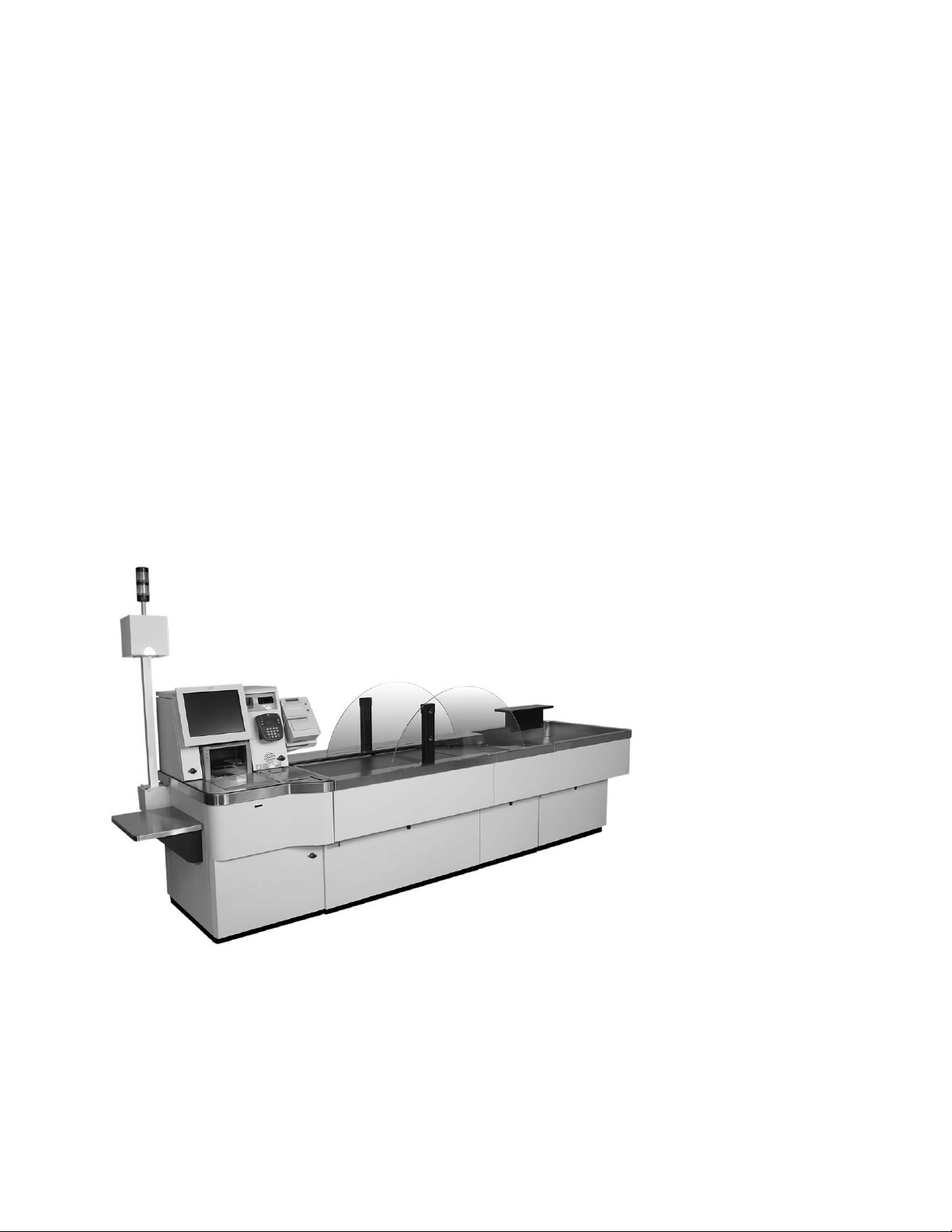
Self Checkout 4845
Parts Manual
Models 131, 15x, 171, 6xx, 8xx, an d BW3
S131-0106-02Updated October 16, 2007
Page 2

Page 3

Self Checkout 4845
Parts Manual
Models 131, 15x, 171, 6xx, 8xx, an d BW3
S131-0106-02Updated October 16, 2007
Page 4

Updated October 16, 2007
Note
Before using this information and the product it supports, be sure to read the “Safety ” on page vii and the general
information under Appendix B, “Notices,” on page 125.
October 2007
This edition applies to IBM Self Checkout Solution, machine type 4845, Models 131, 151, 152, 153, and 171 and
|
IBM Self Checkout Systems, machine type 4845, Models 602, 603, 606, 612, 613, 616, 800, 810, and BW3.
|
Current versions of Retail Store Solutions documentation are available on the IBM Retail Store Solutions Web site at:
www.ibm.com/solutions/retail/store/support. Click Publications.
A form for reader’s comments is also provided at the back of this publication. If the form has been removed, address
your comments to:
IBM Corporation
Retail Store Solutions Information Development
Department ZBDA
PO Box 12195
Research Triangle Park, North Carolina, 27709 USA
you send information to IBM, you grant IBM a nonexclusive right to use or distribute whatever information you
When
supply in any way it believes appropriate without incurring any obligation to you.
© Copyright International Business Machines Corporation 2006, 2007. All rights reserved.
US Government Users Restricted Rights – Use, duplication or disclosure restricted by GSA ADP Schedule Contract
with IBM Corp.
Page 5

Updated October 16, 2007
Contents
Preface . . . . . . . . . . . . . . . . . . . . . . . . . . . .v
How to Use This Parts Manual . . . . . . . . . . . . . . . . . . .v
Identifying a Right Hand or Left Hand Model . . . . . . . . . . . . .v
Related Publications . . . . . . . . . . . . . . . . . . . . . . .vi
Where to Find More Information . . . . . . . . . . . . . . . . . . vii
Safety . . . . . . . . . . . . . . . . . . . . . . . . . . . . vii
Publications Accessibility . . . . . . . . . . . . . . . . . . . . . vii
Providing Feedback . . . . . . . . . . . . . . . . . . . . . . . viii
Uninterruptible Power Supply Option . . . . . . . . . . . . . . . . . viii
Taiwanese Battery Recycling Statement . . . . . . . . . . . . . . . . viii
End of life disposal . . . . . . . . . . . . . . . . . . . . . . . viii
Chapter 1. Core Module . . . . . . . . . . . . . . . . . . . . .1
Assembly 1: Core Module . . . . . . . . . . . . . . . . . . . . .2
Assembly 2: Bill Dispenser . . . . . . . . . . . . . . . . . . . . .6
Assembly 3: Bill Dispenser Main Unit Illustration 1 of 3 . . . . . . . . . . .8
Assembly 4: Bill Dispenser Main Unit Illustration 2 of 3 . . . . . . . . . .10
Assembly 5: Bill Dispenser Main Unit Illustration 3 of 3 . . . . . . . . . .12
Assembly 6: Bill Dispenser Lower Unit . . . . . . . . . . . . . . . .14
Assembly 7: Bill Dispenser Cassette . . . . . . . . . . . . . . . . .16
Assembly 8: Bill Dispenser Communications and Power . . . . . . . . . .18
Assembly 9: Coin Dispensers . . . . . . . . . . . . . . . . . . .20
Assembly 10: Coin Acceptor . . . . . . . . . . . . . . . . . . . .24
Assembly 11: Bill Acceptor . . . . . . . . . . . . . . . . . . . . .26
Assembly 12: Printers TIx and TGx . . . . . . . . . . . . . . . . .28
Assembly 13: Printers TF6 and TM6 . . . . . . . . . . . . . . . . .32
Assembly 14: Printers Fiscal . . . . . . . . . . . . . . . . . . . .36
Assembly 15: Printers Epson . . . . . . . . . . . . . . . . . . . .38
Assembly 16: Magnetic stripe reader and pin pad mount . . . . . . . . .40
Assembly 17: Hand held scanner . . . . . . . . . . . . . . . . . .42
Assembly 18: Countertop . . . . . . . . . . . . . . . . . . . . .44
Assembly 19: Signature Capture and Coupon Acceptor . . . . . . . . . .46
Assembly 20: Lane light and transaction light . . . . . . . . . . . . . .48
Assembly 21: Lane PC, Mouse, and Keyboard . . . . . . . . . . . . .50
Chapter 2. Load Cells, Platens, Plates, and Retaining Fences . . . . . .53
Assembly 22: Load Cell . . . . . . . . . . . . . . . . . . . . . .54
Assembly 23: Platens and Retaining Fences . . . . . . . . . . . . . .56
Chapter 3. Security Conveyor . . . . . . . . . . . . . . . . . . .59
Assembly 24: Security Conveyor . . . . . . . . . . . . . . . . . .60
Chapter 4. Transport Conveyor . . . . . . . . . . . . . . . . . .63
Assembly 25: Transport Conveyor . . . . . . . . . . . . . . . . . .64
Chapter 5. Bagging and Carousel Bagging . . . . . . . . . . . . .67
Assembly 26: Carousel parts . . . . . . . . . . . . . . . . . . . .70
Chapter 6. Wire Bag Rack . . . . . . . . . . . . . . . . . . . .73
Assembly 27: Wire Bag Rack . . . . . . . . . . . . . . . . . . .74
Chapter 7. BOSS . . . . . . . . . . . . . . . . . . . . . . . .77
Assembly 28: BOSS FRUs . . . . . . . . . . . . . . . . . . . .78
© Copyright IBM Corp. 2006, 2007 iii
Page 6

Updated October 16, 2007
Chapter 8. Integrated Paystation . . . . . . . . . . . . . . . . .81
Assembly 29: Paystation . . . . . . . . . . . . . . . . . . . . .82
Chapter 9. EPO (Red) Button . . . . . . . . . . . . . . . . . . .85
Assembly 30: EPO (Red) Button . . . . . . . . . . . . . . . . . .86
Chapter 10. Cables . . . . . . . . . . . . . . . . . . . . . . .89
Assembly 31: Cables . . . . . . . . . . . . . . . . . . . . . . .90
Assembly 32: Power Cords . . . . . . . . . . . . . . . . . . . .92
Chapter 11. Locks and Keys . . . . . . . . . . . . . . . . . . .95
Assembly 33: Currency Lock with Key . . . . . . . . . . . . . . . .96
Assembly 34: Cabinet Lock with Key . . . . . . . . . . . . . . . . .98
Chapter 12. Field Kits and Tools . . . . . . . . . . . . . . . . . 101
Assembly 35: Field Kits and Tools . . . . . . . . . . . . . . . . . 102
Appendix A. Cabinet Parts and Sensors . . . . . . . . . . . . . . 105
Assembly 36: Core Module Cabinet FRUs . . . . . . . . . . . . . . 106
Assembly 37: Security Conveyor and Transport Conveyor Cabinet . . . . .110
Assembly 38: Models 152, 602, and 612 Bagging Cabinet . . . . . . . .112
||
Assembly 39: Models 153, 603, and 613 Bagging Cabinet . . . . . . . .114
Assembly 40: Model N54 Bagging Cabinet . . . . . . . . . . . . . .116
Assembly 41: Models 171, 800, and 810 Bagging Cabinet . . . . . . . .118
Assembly 42: Models 171, 800, and 810 Bumpers, Order Separators, Soft
Goods Shelf . . . . . . . . . . . . . . . . . . . . . . . . 120
Assembly 43: Sensors, Emitters, and Detectors . . . . . . . . . . . . 122
Appendix B. Notices . . . . . . . . . . . . . . . . . . . . . . 125
Electronic emission notices . . . . . . . . . . . . . . . . . . . . 127
Federal Communications Commission (FCC) statement . . . . . . . . 127
European Union EMC Directive conformance statement . . . . . . . . 127
Industry Canada Class A Emission Compliance statement . . . . . . . 128
Avis de conformité aux normes d’Industrie Canada . . . . . . . . . . 128
Germany . . . . . . . . . . . . . . . . . . . . . . . . . 128
Australia and New Zealand . . . . . . . . . . . . . . . . . . . 128
Japanese power line harmonics compliance statement . . . . . . . . . 128
Japanese Voluntary Control Council for Interference (VCCI) statement 129
Cable ferrite requirement . . . . . . . . . . . . . . . . . . . . . 129
Electrostatic Discharge (ESD) . . . . . . . . . . . . . . . . . . . 129
Product Recycling and disposal . . . . . . . . . . . . . . . . . . 129
Battery return program . . . . . . . . . . . . . . . . . . . . . 130
For Taiwan: . . . . . . . . . . . . . . . . . . . . . . . . . 131
For the European Union: . . . . . . . . . . . . . . . . . . . . 131
For California: . . . . . . . . . . . . . . . . . . . . . . . . 131
Flat panel displays . . . . . . . . . . . . . . . . . . . . . . . 132
Monitors . . . . . . . . . . . . . . . . . . . . . . . . . . . 132
Trademarks . . . . . . . . . . . . . . . . . . . . . . . . . . 132
Index . . . . . . . . . . . . . . . . . . . . . . . . . . . . 133
Part number index . . . . . . . . . . . . . . . . . . . . . . . 135
iv Self Checkout 4845: Parts Manual Models 131, 15x, 171, 6xx, 8xx, and BW3
Page 7

Updated October 16, 2007
Preface
This parts manual lists the field replaceable units (FRUs) for the IBM Self Checkout
Solution Models 131, 151, 152, 153, and 171 and the IBM Self Checkout Systems
Models 602, 603, 606, 612, 613, 616, 800, 810, and BW3.
How to Use This Parts Manual
This manual is divided into the following components:
v Core module. See Chapter 1, “Core Module,” on page 1.
v Load cell. See Chapter 2, “Load Cells, Platens, Plates, and Retaining Fences,”
on page 53.
v Security conveyor. See Chapter 3, “Security Conveyor,” on page 59.
v Transport conveyor. See Chapter 4, “Transport Conveyor,” on page 63.
v Bagging module. See Chapter 5, “Bagging and Carousel Bagging,” on page 67.
v Wire Bag Rack. See Chapter 6, “Wire Bag Rack,” on page 73.
v BOSS. See Chapter 7, “BOSS,” on page 77.
v Paystation. See Chapter 8, “Integrated Paystation ,” on page 81.
v EPO. See Chapter 9, “EPO (Red) Button,” on page 85.
v Cables. See Chapter 10, “Cables,” on page 89.
v Locks and keys. See Chapter 11, “Locks and Keys,” on page 95.
v Field kits. See Chapter 12, “Field Kits and Tools,” on page 101.
v Cabinet parts. See Appendix A, “Cabinet Parts and Sensors,” on page 105.
Fasteners, screws, bolts, nuts, grommets and other miscellaneous parts are located
in Chapter 12, “Field Kits and Tools,” on page 101.
Pictures in this manual are for reference only. The actual part might look different.
When ordering, be sure to order the correct part using the machine type and model
number.
Parts without index numbers or FRU numbers are shown for reference only. Some
parts listed by FRU number are not pictured.
Identifying a Right Hand or Left Hand Model
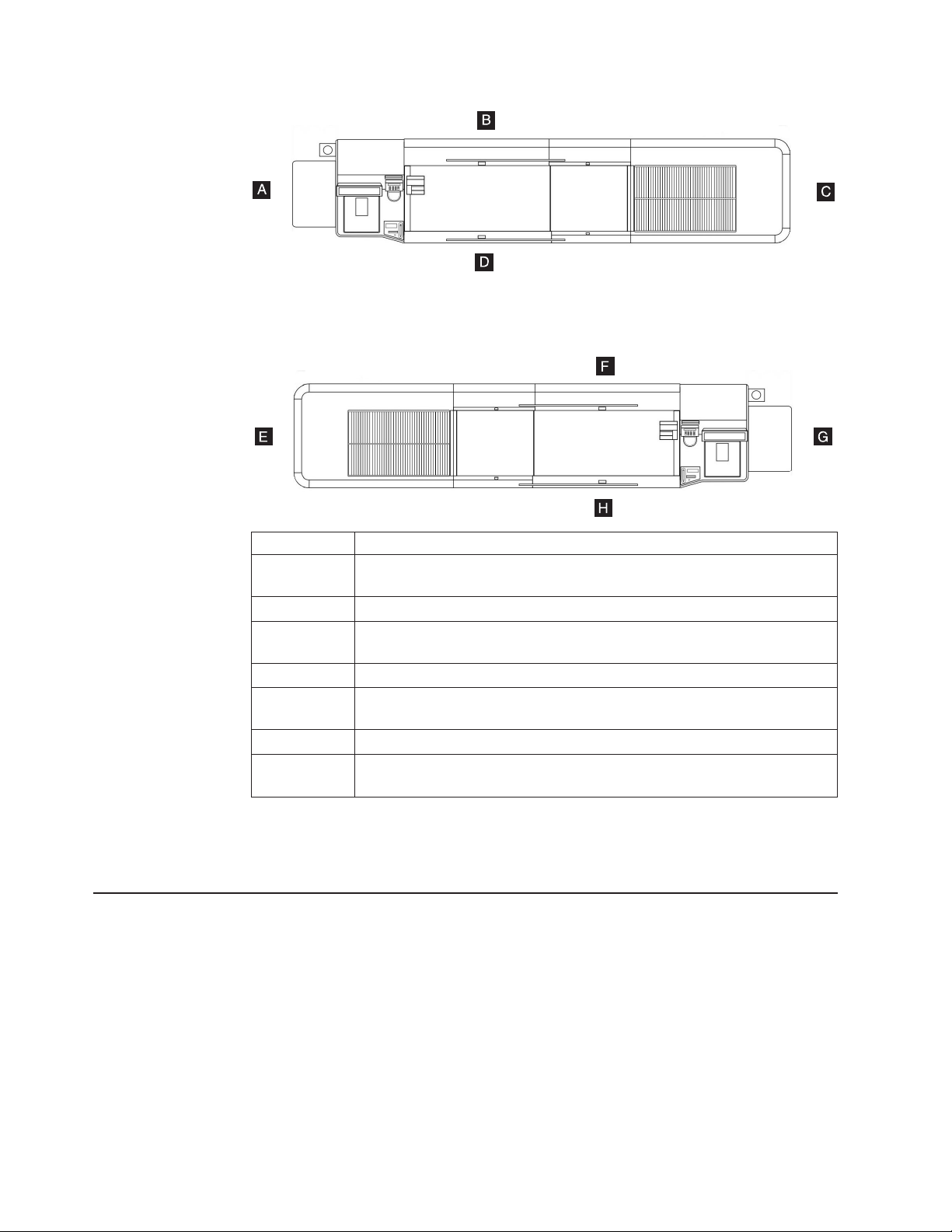
Figure 1 on page vi shows a right-hand lane and a left-hand lane and gives the
naming conventions used in this manual for referring to the sides of the lanes.
© Copyright IBM Corp. 2006, 2007 v
Page 8
Updated October 16, 2007
A Start of right-hand lane.
B Rear side (or left side relative to the transaction flow) of right-hand lane.
C End of right-hand lane.
D Front (customer side or right side relative to the transaction flow) of
E End of left-hand lane.
F Rear side (or right side relative to the transaction flow) of left-hand lane.
G Start of left-hand lane.
H Front (customer side or left side relative to the transaction flow) of left-hand
Figure 1. Right-Hand and Left-Hand Lanes
Related Publications
|
|
|
|
|
|
v IBM Self Checkout 4845 Overview Models 131, 15x, 171, 6xx, 8xx and BW3,
v IBM Self Checkout 4845 Hardware Planning and Installation Guide Models 131,
v IBM Self Checkout Solution 4845 Operations Guide Models 131, 151, 152, 153,
v IBM Self Checkout Solution 4845 Operations Guide Models 131, 151, 152, 153,
v IBM Self Checkout 4845 Operations Guide Models 6xx, 8xx, and BW3 with IBM
The emitters are on the left side of the conveyor.
right-hand lane. The detectors are on the right side of the conveyor.
The detectors are on the right side of the conveyor.
lane. The emitters are on the left side of the conveyor.
GC30-9732
15x, 171, 6xx, 8xx, and BW3, GC30-9733
and 171, GA27-4341 (for software releases prior to Version 5 Release 2)
and 171, with Version 5 Release 2 Software, GC30-9734
Checkout Environment for Consumer-Service Version 6, GC30-9729
vi Self Checkout 4845: Parts Manual Models 131, 15x, 171, 6xx, 8xx, and BW3
Page 9

Updated October 16, 2007
|
|
|
|
|
|
|
v IBM Self Checkout 4845 Hardware Service Guide Models 131, 15x, 171, 6xx,
8xx, and BW3, GY27-0442
v IBM Checkout Environment for Consumer-Service Software Planning, Installation,
and Maintenance Guide for Version 6, SC30-4156
v IBM Checkout Environment for Consumer-Service Software Programming Guide
for Version 6, SC30-4157
v IBM 4610 SureMark Printers Hardware Service Manual, GY27-0355
v IBM 4610 SureMark Printers User Guide, GA27-4151
v IBM 4820 SurePoint Solution Planning, Installation and Service Guide,
GA27-4231
v IBM 4800 SurePOS 720, 740, and 780 Hardware Service Guide, SA27-4329
v IBM 4800 SurePOS 720, 740, and 780 Planning, Installation and Operation
Guide, GA27-4328
v IBM 4694 Point-of-Sale Terminal Hardware Service Manual, SY27-0364
v IBM Safety and Regulatory Information - Read This First, GA27-4004
Where to Find More Information
Current versions of Retail Store Solutions documentation are available on the IBM
Retail Store Solutions Web site at www.ibm.com/solutions/retail/store. Select
Support; then select Publications.
For information about publications not contained on the Web site, contact your IBM
representative or your place of purchase.
Safety
Before you begin to install or service this product, read the safety information in the
IBM Safety and Regulatory Information - Read This First, GA27-4004. This book
describes the safe procedures for installing and servicing IBM products. In addition,
read the following safety information.
DANGER
|
|
|
|
|
|
|
|
Electrical
service on the self checkout product. See IBM Self Checkout 4845 Hardware
Service Guide Models 131, 15x, 171, 6xx, 8xx, and BW3, GY27-0442 for
information about removing power.
DANGER
the self checkout product is equipped with an uninterruptible power
If
supply some devices are still energized after the removal of ac power. The
uninterruptible power supply must be disconnected to ensure that all
power is removed from the self checkout product.
Publications Accessibility
The soft-copy version of this guide and other related publications are
accessibility-enabled.
power must be removed before performing any maintenance or
Preface vii
Page 10
Providing Feedback
Your feedback is important in helping IBM provide accurate and high-quality
information.
You can use either of these ways to provide feedback:
v Go to http://www.ibm.com/solutions/retail/store. Click Support, then click
Publications. Click the publication comments within the introductory text.
Provide the requested information and your comments. Be sure to include the
name and form number of the document in the [Publication ID] field.
v Print and complete the form at the end of this document. Return the form to IBM
by mail or by giving it to an IBM representative.
applicable, include a reference to the specific location of the text (for example, the
If
page or table number) on which you are commenting.
Between major revisions of this document, there might be minor technical updates.
The latest version of this document is available on the Retail Store Solutions Web
site at http://www.ibm.com/solutions/retail/store/support/publications/.
Uninterruptible Power Supply Option
Updated October 16, 2007
This product contains a sealed lead acid battery. The battery must be recycled or
disposed of properly.
In the United States, IBM has established a collection process for reuse, recycling,
or proper disposal of used IBM sealed acid batteries. For information about proper
disposal of these batteries, please contact IBM at 1-800-426-4333. Please have the
IBM part number listed on the battery available prior to your call.
For information about disposal of sealed acid batteries outside the United States, go
to the following URL or contact your local waste disposal facility.
http://www.ibm.com/ibm/environment/products/batteryrecycle.shtml
Taiwanese Battery Recycling Statement
Waste batteries, please recycle.
End of life disposal
This unit must be recycled or discarded according to applicable local and national
regulations. IBM encourages owners of information technology (IT) equipment to
responsibly recycle their equipment when it is no longer needed. IBM offers a
variety of product return programs and services in several countries to assist
equipment owners in recycling their IT products. Information on IBM product
recycling offerings can be found on IBM’s Internet site at http://www.ibm.com/ibm/
environment/products/prp.shtml.
viii Self Checkout 4845: Parts Manual Models 131, 15x, 171, 6xx, 8xx, and BW3
Page 11

Updated October 16, 2007
Notice: This mark applies only to countries within the European Union (EU) and
Norway.
Appliances are labeled in accordance with European Directive 2002/96/EC
concerning waste electrical and electronic equipment (WEEE). The Directive
determines the framework for the return and recycling of used appliances as
applicable throughout the European Union. This label is applied to various products
to indicate that the product is not to be thrown away, but rather reclaimed upon end
of life per this Directive.
In accordance with the European WEEE Directive, electrical and electronic
equipment (EEE) is to be collected separately and to be reused, recycled, or
recovered at end of life. Users of EEE with the WEEE marking per Annex IV of the
WEEE Directive, as shown above, must not dispose of end of life EEE as unsorted
municipal waste, but use the collection framework available to customers for the
return, recycling, and recovery of WEEE. Customer participation is important to
minimize any potential effects of EEE on the environment and human health due to
the potential presence of hazardous substances in EEE. For proper collection and
treatment, contact your local IBM representative.
Disposal of IT products should be in accordance with local ordinances and
regulations.
Preface ix
Page 12

Updated October 16, 2007
x Self Checkout 4845: Parts Manual Models 131, 15x, 171, 6xx, 8xx, and BW3
Page 13
Updated October 16, 2007
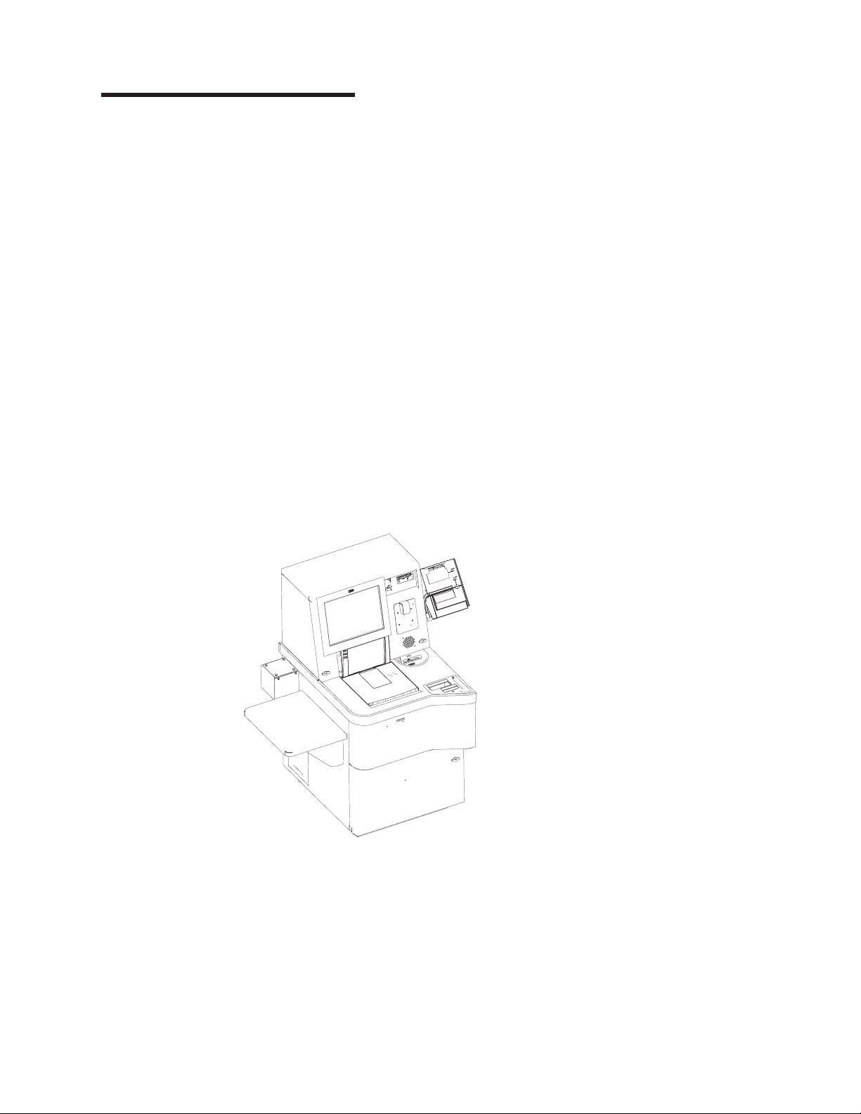
Chapter 1. Core Module
Assembly 1: Core Module . . . . . . . . . . . . . . . . . . . . .2
Assembly 2: Bill Dispenser . . . . . . . . . . . . . . . . . . . . .6
Assembly 3: Bill Dispenser Main Unit Illustration 1 of 3 . . . . . . . . . . .8
Assembly 4: Bill Dispenser Main Unit Illustration 2 of 3 . . . . . . . . . .10
Assembly 5: Bill Dispenser Main Unit Illustration 3 of 3 . . . . . . . . . .12
Assembly 6: Bill Dispenser Lower Unit . . . . . . . . . . . . . . . .14
Assembly 7: Bill Dispenser Cassette . . . . . . . . . . . . . . . . .16
Assembly 8: Bill Dispenser Communications and Power . . . . . . . . . .18
Assembly 9: Coin Dispensers . . . . . . . . . . . . . . . . . . .20
Assembly 10: Coin Acceptor . . . . . . . . . . . . . . . . . . . .24
Assembly 11: Bill Acceptor . . . . . . . . . . . . . . . . . . . . .26
Assembly 12: Printers TIx and TGx . . . . . . . . . . . . . . . . .28
Assembly 13: Printers TF6 and TM6 . . . . . . . . . . . . . . . . .32
Assembly 14: Printers Fiscal . . . . . . . . . . . . . . . . . . . .36
Assembly 15: Printers Epson . . . . . . . . . . . . . . . . . . . .38
Assembly 16: Magnetic stripe reader and pin pad mount . . . . . . . . .40
Assembly 17: Hand held scanner . . . . . . . . . . . . . . . . . .42
Assembly 18: Countertop . . . . . . . . . . . . . . . . . . . . .44
Assembly 19: Signature Capture and Coupon Acceptor . . . . . . . . . .46
Assembly 20: Lane light and transaction light . . . . . . . . . . . . . .48
Assembly 21: Lane PC, Mouse, and Keyboard . . . . . . . . . . . . .50
© Copyright IBM Corp. 2006, 2007 1
Page 14
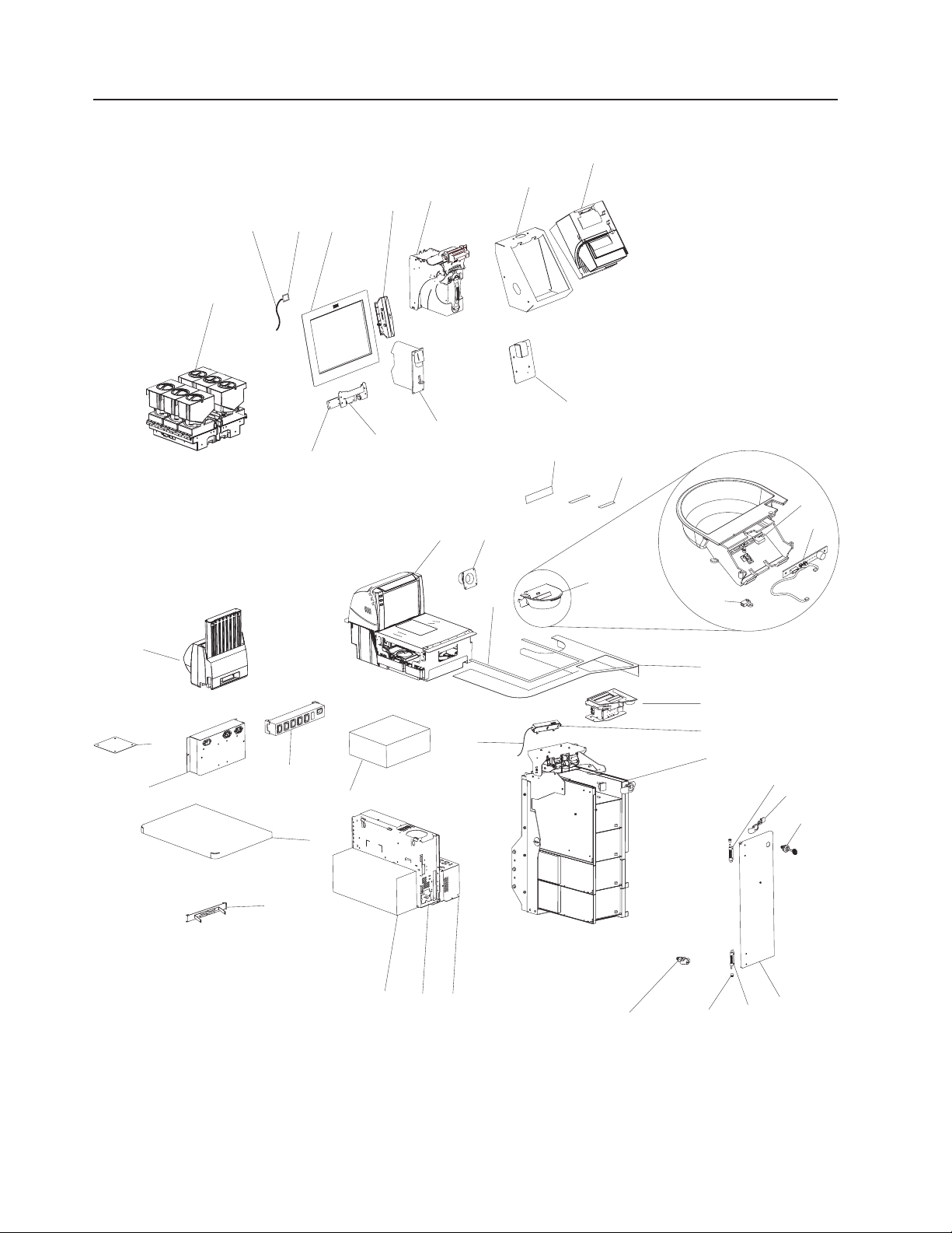
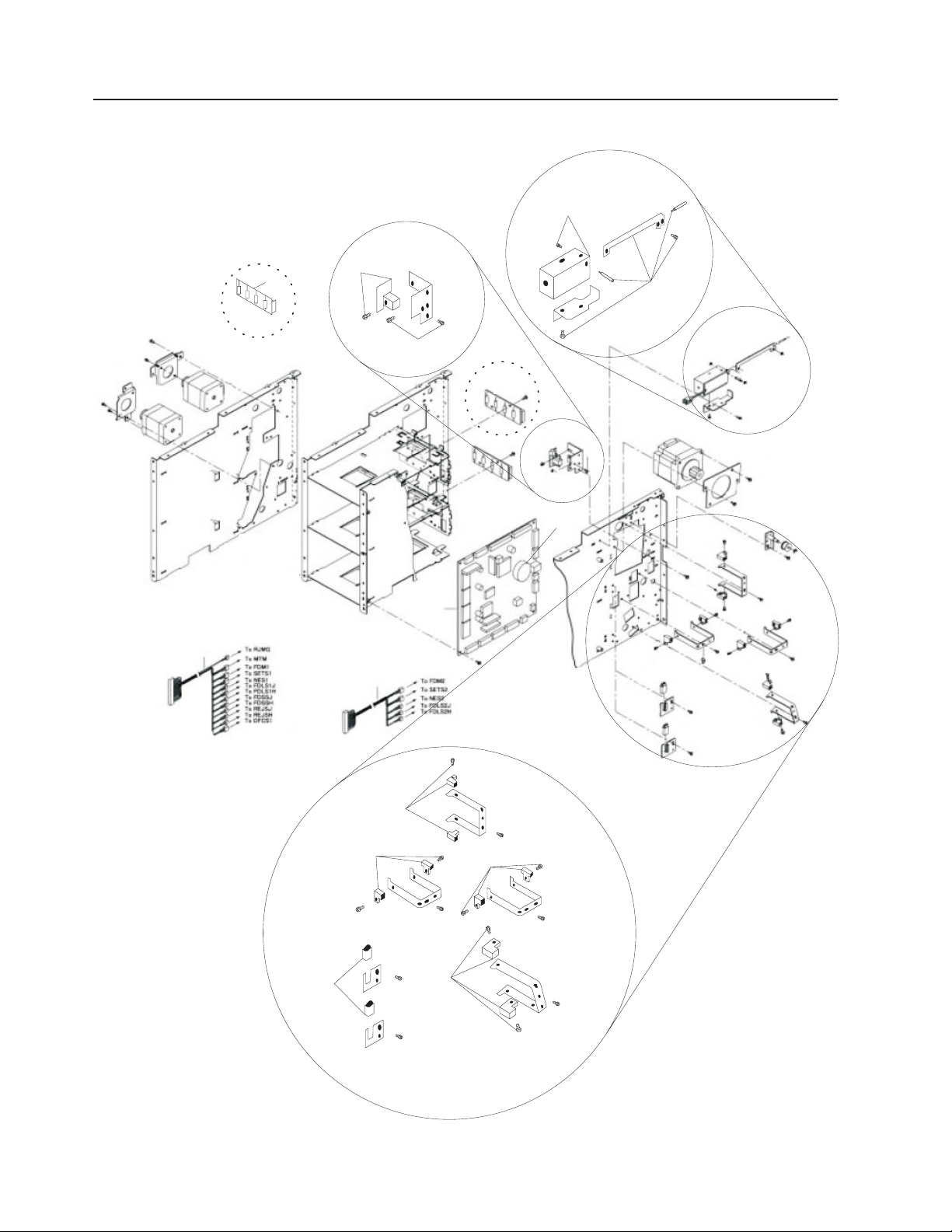
Assembly 1: Core Module
Updated October 16, 2007
8
7
6
5
2
3
4
1
9
10
11
12
16
17
18b
13
14
19
18
15
18c
40
20
21
22
24
25
26
38
39
23
37
36
27
35
41
34
3233
31
30
29
28
2 Self Checkout 4845: Parts Manual Models 131, 15x, 171, 6xx, 8xx, and BW3
Page 15

Updated October 16, 2007
Assembly 1: (continued)
Asm–
Index
Part
Number
Units Description
1– See “How to Use This Parts Manual” on page v for general parts manual
information, including finding and ordering parts. See “Identifying a Right
Hand or Left Hand Model” on page v for how to identify left hand and right
hand models.
–1 1 Hopper coin dispenser. See “Assembly 9: Coin Dispensers” on page 20 for a
complete listing of coin dispenser parts.
–2 40M9470 1 Cable, Reset Button
–3 40M9469 1 Button Assembly, Reset (on upper door behind monitor)
–4 41J9296 1 Monitor, IBM SurePoint Model 4820 - 5WN (USB with I/O support), pearl white
(BOSS) (machines built after July 31, 2006)
–4 40M9366 1 Monitor, IBM SurePoint Model 4820 - 5WN (USB with I/O support), pearl white
(BOSS)
–4 41J9298 1 Monitor, IBM SurePoint Model 4820 - 5WN (USB without I/O support), pearl white
(lane)
–4 41J9295 1 Monitor, IBM SurePoint Model 4820 - 5GN (USB with I/O support), iron gray
(RAP/BOSS)
–4 41J9297 1 Monitor, IBM SurePoint Model 4820 - 5GN (USB without I/O support), iron gray
(lane) (machines built after July 31, 2006)
–4 28R5455 1 Monitor, IBM SurePoint Model 4820 - 5GN (USB without I/O support), iron gray
(lane)
–4 44M1846 1 Monitor, IBM SurePoint Model 4820 - 5GN (RS232 touch I/O), iron gray (EMEA)
–4 44D1157 1 Monitor, flat, T115 TFT, Model 4942 - 15X, black
– 14J1054 1 3.8 cable, Analog video Monitor, IBM SurePoint Model 4820.
– 42M5667 1 3.8 cable, Analog video Monitor, IBM SurePoint Model 4820 (machines built after
July 31, 2006).
– 01L1637 1 3.8 cable, USB Touchscreen Monitor, IBM SurePoint Model 4820.
– 42M5632 1 3.8 cable, USB Touchscreen Monitor, IBM SurePoint Model 4820 (machines built
after July 31, 2006).
–5 40N6220 1 Magnetic stripe reader, pearl white (attaches to the 4820 display)
–5 40N6224 1 Magnetic stripe reader, iron gray (attaches to the 4820 display)
–6 1 Bill acceptor assembly. See “Assembly 11: Bill Acceptor” on page 26 for a complete
listing of bill acceptors and parts.
–7 See “Assembly 12: Printers TIx and TGx” on page 28.
–8 See “Assembly 12: Printers TIx and TGx” on page 28.
–9 41E1851 1 Cover plate if there is no pinpad (not shown)
–9 Magnetic strip reader mount and pin pad mounting. See “Assembly 16: Magnetic
stripe reader and pin pad mount” on page 40).
–10 1 Coin acceptor. See “Assembly 10: Coin Acceptor” on page 24 for a complete listing
of coin acceptors and parts.
–11 41E1849 1 SurePoint display hinge
–12 41E1850 1 Display mounting kit (includes 4 - shoulder washers, 8 - screws, 4 - M4 top inserts,
1 - spacer plate, 1 - limiter (right hand), and 1 - limiter (left hand).
–13 1 Scanner/scale (shown for reference only)
– 41D7211 1 Scanner Adapter plate, Fujitsu (customer furnished scanner)
–14 28R3786 1 Speaker
–14 41D7083 1 Speaker (machines built after July 31, 2006)
– 41K6370 1 Speaker Audio cable (not shown)
–15 1 Scanner/scale contrast label (shown for reference only)
–16 42K0356 1 Label, Cash Out, right hand
–16 42K0360 1 Label, Cash Out, left hand
–17 42K0358 1 Label, Coupon
–18 41J9839 1 Cash cup assembly, right hand
–18 41J9841 1 Cash cup assembly, left hand
Chapter 1. Core Module 3
Page 16

Assembly 1: (continued)
Updated October 16, 2007
Asm–
Index
–18 41K6356 1 Cash cup, left hand
–18 41K6355 1 Cash cup, right hand
–18B 41D7080 1 Detector, cash cup
–18C 41D7082 1 Emitter, cash cup
–19 41J9838 1 Sensor card, cash cup
–20 1 Countertop. See “Assembly 18: Countertop” on page 44 for a complete listing of
Part
Number
Units Description
available countertops.
–21 1 Signature capture device. See “Assembly 19: Signature Capture and Coupon
Acceptor” on page 46 for a complete listing of signature capture parts.
–22 41J9916 1 Proximity sensor
–23 40M9472 1 Proximity sensor cable
–24 1 Bill dispenser assembly. See “Assembly 2: Bill Dispenser” on page 6.
–25 41D9329 1 Hinge, upper hinge for right hand door (lower hinge for the left hand door)
–26 41K6087 1 Safe door cam lock
–27 41K6120 1 Safe door lock, currency lock with key. See Chapter 11, “Locks and Keys,” on page
95.
–28 41K6089 1 Safe door, right hand
–28 41K6090 1 Safe door, left hand
–29 41D9330 1 Hinge, lower hinge for the right hand door (upper hinge for the left hand door)
–30 41K6166 1 Bushing, hinge
–31 1 Keylock, cabinet lock with key. See Chapter 11 , “Locks and Keys,” on page 95.
–32 41J9135 1 Security controller
–33 1 Lane PC. See “Assembly 21: Lane PC, Mouse, and Keyboard” on page 50.
–34 41D9359 1 Uninterruptible power supply, 230V/400W (BK650EI) (machines built after July 31,
2006)
–34 41D7068 1 Uninterruptible power supply, 115V (replaces 28R3582) (SU620)
– 44D0872 1 APC RBC4 Uninterruptible power supply replacement battery (for SU620)
– 44D0874 1 APC RBC5 Uninterruptible power supply replacement battery (for SU700INET)
– 44D1125 1 APC RBC17 Uninterruptible power supply replacement battery (for BK650EI)
(machines built after July 31, 2006)
–35 41K6161 1 Customer or basket shelf
–36 1 Sensormatic Scan Max Pro controller (shown for reference only)
–37 28R3587 1 Power strip, 5 Outlet, IEC320 (International, not US and Canada)
– 28R3595 1 Power strip, 115V, US, Canada, 8 outlet (not shown)
– 41D7775 1 Power strip IEC320 C-14 to 5 EU1-16R, French
– 44D0448 1 Power strip, IEC 60320 C-14 to 5 UK-13R
–38 41J9542 1 Filter/power box
–39 41E1865 1 Cover plate, lane light
–40 1 Cassette Coin dispenser. See “Assembly 9: Coin Dispensers” on page 20 for a
complete listing of coin dispenser parts.
–41 41J9891 1 Bracket for vacuum florescent (VF) display (for some fiscal printers)
– 40N4716 1 3.8m Printer USB cable (not shown)
– 41K6369 1 PC Audio cable (not shown)
– 41D7073 1 Cable, 6 foot, DB9, male/female, used for uninterruptible power supply data (not
shown)
– 41E1832 1 Power strip mounting plate (not shown)
– 28R3559 1 Power jumper cord, IEC 60320 C-14 to NEMA 5-15R (not shown)
– 39M5376 1 Power jumper cord, IEC320, 2-0M
– 41K6368 1 Power supply, Security controller (not shown)
– See Appendix A, “Cabinet Parts and Sensors,” on page 105 for available
cabinet FRUs.
– See Chapter 10, “Cables,” on page 89 for additional cable FRUs.
4 Self Checkout 4845: Parts Manual Models 131, 15x, 171, 6xx, 8xx, and BW3
Page 17

Updated October 16, 2007
Chapter 1. Core Module 5
Page 18
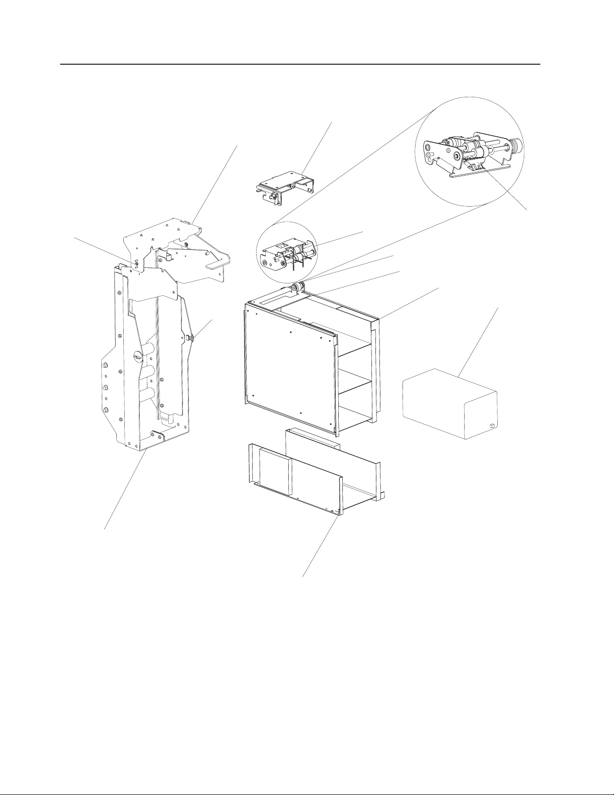
Assembly 2: Bill Dispenser
11
10
Updated October 16, 2007
2
1
3a
3
4
5
6
7
9
8
6 Self Checkout 4845: Parts Manual Models 131, 15x, 171, 6xx, 8xx, and BW3
Page 19

Updated October 16, 2007
Assembly 2: (continued)
Asm–
Index
Part
Number
Units Description
2– See “How to Use This Parts Manual” on page v for general parts manual
information, including ordering parts. See “Identifying a Right Hand or Left Hand
Model” on page v for how to identify left hand and right hand models.
–1 41E1866 1 Bracket assembly, bill dispenser presenter mounting
–2 41K6318 1 Mount, bill dispenser (remains in cabinet)
–3 41K6319 1 Presenter, bill dispenser
–3A 41D7135 1 Sensor prism, presenter
–4 41D7137 1 Gear train, presenter gears
–5 41D7139 1 Presenter sensor plate
–6 41D7213 1 Bill dispenser, universal, 2 bin
–7 41D7053 1 Cartridge, universal, bill dispenser (includes configuration instructions and labels for
each currency). See “Assembly 7: Bill Dispenser Cassette” on page 16 for
additional component details.
–8 41D7215 1 Additional denomination module
–9 41K6398 1 Slide assembly, bill dispenser (with counter weight)
–10 41K6399 1 Mount parts, bill dispenser (pivot, screws, latch spring)
–11 41D8199 1 Set screw, bill dispenser presenter mount
– 41D7123 1 Presenter unit cable assembly (not shown)
– 41D7127 1 Presenter unit exit sensor (not shown)
Chapter 1. Core Module 7
Page 20
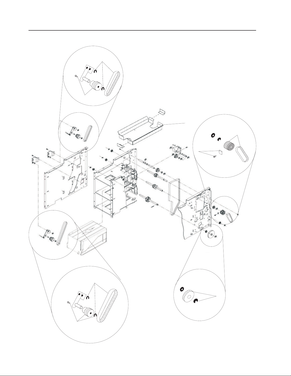
Assembly 3: Bill Dispenser Main Unit Illustration 1 of 3
1
1
5
2
Updated October 16, 2007
2
4
4
8 Self Checkout 4845: Parts Manual Models 131, 15x, 171, 6xx, 8xx, and BW3
3
Page 21

Updated October 16, 2007
Assembly 3: (continued)
Asm–
Index
Part
Number
Units Description
3– See “How to Use This Parts Manual” on page v for general parts manual
information, including ordering parts. See “Identifying a Right Hand or Left Hand
Model” on page v for how to identify left hand and right hand models.
–1 41K6289 1 Timing kit, main unit channel 1 (includes 1 gear pulley, 2 retaining rings, 1 spring, 1
timing belt)
–2 41D7119 1 Timing kit, intermodule (includes 1 timing belt, 1 washer, 1 screw, 1 pulley)
–3 41K6303 1 Main/lower unit interconnect (includes 1 gear, 1 pin, 1 retainer E ring)
–4 41K6290 1 Timing kit, main unit channel 2 (includes 1 gear pulley, 2 retaining rings, 1 spring, 1
timing belt)
–5 41D7133 1 Reject bin
Chapter 1. Core Module 9
Page 22
Assembly 4: Bill Dispenser Main Unit Illustration 2 of 3
1
1
Updated October 16, 2007
10 Self Checkout 4845: Parts Manual Models 131, 15x, 171, 6xx, 8xx, and BW3
1
Page 23

Updated October 16, 2007
Assembly 4: (continued)
Asm–
Index
Part
Number
Units Description
4– See “How to Use This Parts Manual” on page v for general parts manual
information, including ordering parts. See “Identifying a Right Hand or Left Hand
Model” on page v for how to identify left hand and right hand models.
–1 41D7105 1 Scraper kit (includes 1 large and 1 small scraper, 2 screws (1 for each scraper)
Chapter 1. Core Module 11
Page 24
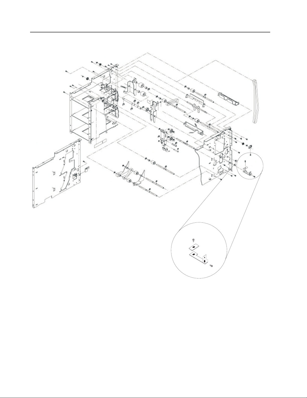
Assembly 5: Bill Dispenser Main Unit Illustration 3 of 3
3
Updated October 16, 2007
1
2
3
2
9
8
7
6
4
4
5
4
4
12 Self Checkout 4845: Parts Manual Models 131, 15x, 171, 6xx, 8xx, and BW3
Page 25

Updated October 16, 2007
Assembly 5: (continued)
Asm–
Index
Part
Number
Units Description
5– See “How to Use This Parts Manual” on page v for general parts manual
information, including ordering parts. See “Identifying a Right Hand or Left Hand
Model” on page v for how to identify left hand and right hand models.
–1 1 Printed circuit board (reed switch type, sometimes referred to as a PCB) - not
serviceable (replace the bill dispenser assembly)
–2 41D7103 1 Thickness sensor (includes 1 sensor, 2 screws, 1 shaft, 1 retaining ring)
–3 41D7107 1 Solenoid kit (includes 1 solenoid, 3 screws, 3 retaining rings, 1 spring, 1 shaft, 1
MG arm)
–4 41D7563 1 Bill dispenser sensor kit (includes 2 sensors, 2 screws)
–5 41D7125 1 Cassette sensor, bill dispenser
–6 41D7113 1 Cable, CAU 2 Main unit controlled access unit
–7 41D7111 1 Cable, CAU 1 Main unit
–8 41D7109 1 Printed circuit board (main unit, sometimes referred to as a PCB)
–9 04G5389 1 Battery, Lithium
–9 41D7610 1 Battery, Lithium bill dispenser (machines built after July 31, 2006)
Chapter 1. Core Module 13
Page 26
Assembly 6: Bill Dispenser Lower Unit
9
9
9
Updated October 16, 2007
1
2
4
7
6
5
14 Self Checkout 4845: Parts Manual Models 131, 15x, 171, 6xx, 8xx, and BW3
8
3
Page 27

Updated October 16, 2007
Assembly 6: (continued)
Asm–
Index
Part
Number
Units Description
6– See “How to Use This Parts Manual” on page v for general parts manual
information, including ordering parts. See “Identifying a Right Hand or Left Hand
Model” on page v for how to identify left hand and right hand models.
–1 41K6308 1 Lower unit timing belt
–2 41K6306 1 Lower unit gear 20 kit (includes 1 pin, 1 gear, 2 retaining E rings)
–3 41D7217 1 Lower unit gear 34 kit (includes 1 pin, 1 gear, 1 retaining E ring)
–4 41K6307 1 Lower unit gear 54 kit (includes 1 gear, 1 retaining ring)
–5 41D7121 1 Lower unit gear 44 kit (includes 1 pin, 1 gear, 1 retaining ring)
–6 41D7563 1 Bill dispenser sensor kit. See 5–4 on page 13.
–7 41D7125 1 Cassette sensor, bill dispenser
–8 41K6309 1 Cable assembly, lower unit
–9 41K6291 1 Timing kit, lower unit (includes 1 gear pulley, 2 retaining rings, 1 spring, 1 timing
belt)
Chapter 1. Core Module 15
Page 28
Assembly 7: Bill Dispenser Cassette
Updated October 16, 2007
1
1
1
1
1
1
1
1
1
1
1
1
1
1
1
1
9
1
1
1
1
4
5
5
8
7
2
3
6
2
3
3
3
3
3
16 Self Checkout 4845: Parts Manual Models 131, 15x, 171, 6xx, 8xx, and BW3
Page 29

Updated October 16, 2007
Assembly 7: (continued)
Asm–
Index
Part
Number
Units Description
7– See “How to Use This Parts Manual” on page v for general parts manual
information, including ordering parts. See “Identifying a Right Hand or Left Hand
Model” on page v for how to identify left hand and right hand models.
– 41D7053 1 Cassette, universal bill dispenser
–1 41D7115 1 Pick roller kit (includes 1 passway, 1 spacer, 2 shaft assemblies, 2 pulleys, 2
one-way rollers, 3 gears, 2 rollers, 2 bearings, 1 timing belt, 2 screws, 2 nuts)
–2 41K6298 1 Cassette pressure plate kit (includes 1 pressure plate, 1 spring, 1 rubber sheet)
–3 41D7117 1 Cassette currency rails kit (includes 2 adjuster S, 4 leaf springs, 1 adjuster R, 4
screws, 1 rear pressure, 1 spring, 1 rubber sheet)
–4 41K6300 1 Cassette handle
–5 41K6301 1 Cassette magnets (package of 2)
–6 41D7131 1 Cassette prism
–7 42K0061 1 Cassette label "1" (not shown)
–7 42K0062 1 Cassette label "5" (not shown)
–7 42K0063 1 Cassette label "10" (not shown)
–7 42K0064 1 Cassette label "20" (not shown)
–8 41K6322 1 Cassette latching hook
–9 44M1840 1 Cassette latch
– 41D7129 1 Low note sensor
Chapter 1. Core Module 17
Page 30
Assembly 8: Bill Dispenser Communications and Power
Updated October 16, 2007
1 2 3
18 Self Checkout 4845: Parts Manual Models 131, 15x, 171, 6xx, 8xx, and BW3
Page 31

Updated October 16, 2007
Assembly 8: (continued)
Asm–
Index
Part
Number
Units Description
8– See “How to Use This Parts Manual” on page v for general parts manual
information, including ordering parts. See “Identifying a Right Hand or Left Hand
Model” on page v for how to identify left hand and right hand models.
–1 39M5374 1 1.0m power jumper cord (Uninterruptible power supply to Controller Uninterruptible
power supply In)
–2 40M9400 1 Cable, bill dispenser data
–3 41K6080 1 Power dongle, 24V
– 40N5606 1 Power adapter (power supply), 24V (not shown) (machines built after July 31, 2006)
Chapter 1. Core Module 19
Page 32

Assembly 9: Coin Dispensers
Updated October 16, 2007
20 Self Checkout 4845: Parts Manual Models 131, 15x, 171, 6xx, 8xx, and BW3
Page 33

Updated October 16, 2007
Assembly 9: (continued)
Asm–
Index
Part
Number
Units Description
9– See “How to Use This Parts Manual” on page v for general parts manual
information, including ordering parts. See “Identifying a Right Hand or Left Hand
Model” on page v for how to identify left hand and right hand models.
– 41D7047 1 Hopper coin dispenser, UK (includes assembly index # 1 ,9, 10, 11 and the base)
– 44D1294 1 Hopper coin dispenser, Euro (includes assembly index # 1 ,9, 10, 11 and the base)
– 41D7043 1 Hopper coin dispenser, US (includes assembly index # 1 ,9, 10, 11 and the base)
– 41D7045 1 Hopper coin dispenser, Canada (includes assembly index # 1 ,9, 10, 11 and the
base)
– 41D7051 1 Hopper coin dispenser, Australia (includes assembly index # 1 ,9, 10, 11 and the
base)
–1 41J7615 1 Hopper, coin dispenser, US/Canada .01
–1 41J7616 1 Hopper, coin dispenser, US/Canada .05
–1 41J7617 1 Hopper, coin dispenser, US/Canada .10
–1 41J7618 1 Hopper, coin dispenser, US/Canada .25
–1 41J7619 1 Hopper, coin dispenser, US/Canada 1.00
–1 41J7620 1 Hopper, coin dispenser, Canada 2.00
–1 41J7621 1 Hopper, coin dispenser, UK .01
–1 41J7622 1 Hopper, coin dispenser, UK .02
–1 41J7623 1 Hopper, coin dispenser, UK .05
–1 41J7624 1 Hopper, coin dispenser, UK .10
–1 41J7625 1 Hopper, coin dispenser, UK .20
–1 41J7626 1 Hopper, coin dispenser, UK 1.00
–1 41J7627 1 Hopper, coin dispenser, Euro .01
–1 41J7628 1 Hopper, coin dispenser, Euro .02
–1 41J7629 1 Hopper, coin dispenser, Euro .05
–1 41J7630 1 Hopper, coin dispenser, Euro .10
–1 41J7631 1 Hopper, coin dispenser, Euro .20
–1 41J7632 1 Hopper, coin dispenser, Euro .50
–1 41J7633 1 Hopper, coin dispenser, Euro 1.00
–1 41J7634 1 Hopper, coin dispenser, Euro 2.00
–2 41K6082 1 Hopper mount assembly, right hand (includes slide rails)
–2 41K6086 1 Hopper mount assembly, left hand (includes slide rails)
–3 1 Keylock. See Chapter 11 , “Locks and Keys,” on page 95.
–4 41D7076 1 Reject plate, coin, right hand
–4 41D7078 1 Reject plate, coin, left hand
–5 41K6363 1 Chute, coin, right hand, for both hopper and cassette coin dispensers
–5 41K6364 1 Chute, coin, left hand, for both hopper and cassette coin dispensers
–6 41D7813 1 Upper coin chute assembly, right hand
–6 41D7815 1 Upper coin chute assembly, left hand
–8 41K6088 1 Lock, cam
–9 41J7638 1 Hopper coin dispenser rotor, US/Canada .01
–9 41J7639 1 Hopper coin dispenser rotor, US/Canada .05
–9 41J7640 1 Hopper coin dispenser rotor, US/Canada .10
–9 41J7641 1 Hopper coin dispenser rotor, US .25, UK .10
–9 41J7642 1 Hopper coin dispenser rotor, US/Canada 1.00
–9 41J7643 1 Hopper coin dispenser rotor, Canada 2.00
–9 41J7644 1 Hopper coin dispenser rotor, UK .01
–9 41J7645 1 Hopper coin dispenser rotor, UK .02
–9 41J7646 1 Hopper coin dispenser rotor, UK .05
–9 41J7648 1 Hopper coin dispenser rotor, UK .20 Euro .05
–9 41J7649 1 Hopper coin dispenser rotor, UK 1.00
–9 44D1296 1 Hopper coin dispenser rotor, Euro .01
–9 41J7651 1 Hopper coin dispenser rotor, Euro .02/.10
Chapter 1. Core Module 21
Page 34

Assembly 9: (continued)
Updated October 16, 2007
Asm–
Index
–9 41J7654 1 Hopper coin dispenser rotor, Euro .20/1.00
–9 41J7655 1 Hopper coin dispenser rotor, Euro .50/2.00
–10 41J7658 1 Hopper coin dispenser bin, clear
–11 41J7659 1 Hopper coin dispenser bin cover kit (includes cover body, label set for US, UK,
Part
Number
Units Description
Euro
–13 41K6353 1 Coin dispenser stand
–14 41K6077 1 Coin dispenser with cable and power supply (does not include cartridge/cassette)
(unconfigured)
–14 41K7207 1 Coin dispenser with cable and power supply (does not include cartridge/cassette),
US
–14 41K7208 1 Coin dispenser with cable and power supply (does not include cartridge/cassette),
Canada
–14 41K7209 1 Coin dispenser with cable and power supply (does not include cartridge/cassette),
Euro
–14 41K7210 1 Coin dispenser with cable and power supply (does not include cartridge/cassette),
Australia
–14 41K7211 1 Coin dispenser with cable and power supply (does not include cartridge/cassette),
UK
–15 28R3678 1 Cassette, coin, Canada
–15 28R3679 1 Cassette, coin, Euro
–15 28R3680 1 Cassette, coin, Australia
–15 28R5399 1 Cassette, coin, UK
–15 28R5466 1 Cassette, coin, US
–16 41D8231 1 Corner plug, coin dispenser (used to block loading of coins in one or more stacks)
–17 41D8229 1 Wing clip, coin dispenser cassette (used to block dispensing of coins from one or
more stacks)
–18 41D8060 1 Coin cassette deflector, right hand
–18 41D8062 1 Coin cassette deflector, left hand
– 41D7403 1 Power supply, cassette coin dispenser, 32 VDC (not shown)
– 41D7404 1 Power supply, hopper coin dispenser, 24 VDC (not shown)
– 41K6352 1 Coin dispenser signal cable for both hopper and cassette dispensers (not shown)
– 39M5377 1 Power jumper cord, UK, EURO, Australia (not shown)
– 39M5081 1 Power jumper cord , US, Canada (not shown)
– 41J7635 1 Cable harness, position 1,2, and 3, hopper coin dispenser (not shown)
– 41J7636 1 Cable harness, position 4,5, and 6 hopper coin dispenser (not shown)
– 41J7637 1 Card assembly, hopper coin dispenser (not shown)
22 Self Checkout 4845: Parts Manual Models 131, 15x, 171, 6xx, 8xx, and BW3
Page 35

Updated October 16, 2007
Chapter 1. Core Module 23
Page 36

Assembly 10: Coin Acceptor
Updated October 16, 2007
1
2
3
4
5
6
7
8
9
10
24 Self Checkout 4845: Parts Manual Models 131, 15x, 171, 6xx, 8xx, and BW3
Page 37

Updated October 16, 2007
Assembly 10: (continued)
Asm–
Index
Part
Number
Units Description
10– See “How to Use This Parts Manual” on page v for general parts manual
information, including ordering parts. See “Identifying a Right Hand or Left Hand
Model” on page v for how to identify left hand and right hand models.
–1 41D9345 1 Coin Acceptor, MEI CF9520, US, with side reject plate (part 10–2) (machines built
after July 31, 2006)
–1 41D8051 1 Coin Acceptor MEI, CF9520, US, rejects $0.01, with side reject plate (part 10–2)
(machines built after July 31, 2006)
–1 41J6735 1 Coin Acceptor MEI, CF9520, US, with side reject plate (part 10–2)
–1 41D9347 1 Coin Acceptor, MEI CF9520, UK, with side reject plate (part 10–2) (machines built
after July 31, 2006)
–1 41J6736 1 Coin Acceptor MEI, CF9520, UK, with side reject plate (part 10–2)
–1 41D9346 1 Coin Acceptor, MEI CF9520, Canada, with side reject plate (part 10–2) (machines
built after July 31, 2006)
–1 41J6737 1 Coin Acceptor, Canada, with side reject plate (part 10–2)
–1 41D9348 1 Coin Acceptor, MEI CF9520, Euro, with side reject plate (part 10–2) (machines built
after July 31, 2006)
–1 41J6738 1 Coin Acceptor, Euro, with side reject plate (part 10–2)
–1 41D9349 1 Coin Acceptor, MEI CF9520, Australian, with side reject plate (part 10–2) (machines
built after July 31, 2006)
–1 41J6739 1 Coin Acceptor, MEI CF9520, Australian, with side reject plate (part 10–2)
–2 41J8231 1 Coin acceptor side reject plate
–3 28R3292 1 Coin acceptor mounting plate
–4 42K0052 1 Cash acceptance bezel, right hand
–4 42K0053 1 Cash acceptance bezel, left hand
–5 42K0355 1 Label, cash in, right hand
–5 42K0359 1 Label, cash in, left hand
–6 41K6593 1 Shaft, cash acceptance bezel
–7 41J8076 1 Coin deflector, right hand
–7 42K0058 1 Coin deflector, left hand
–8 44D0245 1 Coin tray guide, right hand
–8 44D0246 1 Coin tray guide, left hand
–9 41K6160 1 Coin tray
–10 41K6363 1 Chute, coin RH
–10 41K6364 1 Chute, coin LH
– 28R5566 1 Ferrite core (installed on signal cable)
– 41K6354 1 Coin acceptor cable, US/Canada (not shown)
– 41K6359 1 Coin acceptor cable, EMEA/Australia (not shown)
Chapter 1. Core Module 25
Page 38

Assembly 11: Bill Acceptor
Updated October 16, 2007
2
3
1
6
7
8
4
5
26 Self Checkout 4845: Parts Manual Models 131, 15x, 171, 6xx, 8xx, and BW3
Page 39

Updated October 16, 2007
Assembly 11: (continued)
Asm–
Index
Part
Number
Units Description
11– See “How to Use This Parts Manual” on page v for general parts manual
information, including ordering parts. See “Identifying a Right Hand or Left Hand
Model” on page v for how to identify left hand and right hand models.
– 41J9330 1 Mars SC6607R bill acceptor, US
– 41D7250 Mars SC6607R bill acceptor, US (machines built after July 31, 2006)
– 40M9343 1 Mars SC6607R bill acceptor, Australian firmware
– 41D7254 1 Mars SC8307R bill acceptor, Euro, UK
– 41E1449 1 Mars SC8307R bill acceptor, Canadian firmware
– 40M9341 1 Mars SC8307R bill acceptor, UK firmware
– 40M9342 1 Mars SC8307R bill acceptor, Euro firmware
–1 44D0258 1 Chassis with connector cables, Mars SC bill acceptor (does not include 11–6 or
11–7)
–2 41D7249 1 Head, Mars SC6607R bill acceptor, US, Australia (replaces 41J9486)
–2 41D7252 1 Head, Mars SC8307R bill acceptor, UK, Euro, Canada
–2 41D9700 1 Head, Mars SC8307R bill acceptor, Canadian firmware
–2 41D9701 1 Head, Mars SC8307R bill acceptor, UK firmware
–2 41D9702 1 Head, Mars SC8307R bill acceptor, Euro firmware
–2 41D9703 1 Head, Mars SC6607R bill acceptor, Australian firmware
–3 41D7251 1 Universal bezel with gap filler, Mars SC6607R bill acceptor, US, Australia (replaces
28R3477)
–3 41D7253 1 Universal bezel with gap filler, Mars SC8307R bill acceptor, UK, Euro, Canada
(replaces 28R5028)
–4 41D7248 1 Cash Box, Mars SC bill acceptors (replaces 28R3492)
–5 28R3684 1 Mars SC bill acceptor data cable
–6 41K6109 1 Bill acceptor mounting bracket
–7 44D0260 1 Interface card, MEI SC series bill acceptor
–8 44D0262 1 Edge connector, MEI SC series bill acceptor
Chapter 1. Core Module 27
Page 40

Assembly 12: Printers TIx and TGx
Updated October 16, 2007
3
5
6
4
2
1
7
8
9
10
28 Self Checkout 4845: Parts Manual Models 131, 15x, 171, 6xx, 8xx, and BW3
Page 41

Updated October 16, 2007
Assembly 12: (continued)
Asm–
Index
Part
Number
Units Description
12– Printer, left hand iron gray
–1 41J9442 1 Printer shelf, TI and TG, left hand, iron gray
–2 41J9770 1 Hole cover, round, iron gray
–3 41J9457 1 Hole cover, oval, iron gray
–4 41J8809 1 Rivet, black push in
–5 41J9447 1 Printer, Catalina, back cover, iron gray
–6 41J9438 1 Printer, Catalina, left hand auxiliary mounting bracket iron gray (used with 41J9442)
–7 41J9452 1 Printer, Catalina, mounting bracket, iron gray (used with 41J9438)
–8 41J9416 1 Locking bracket, iron gray
–9 1 Catalina Printer (customer furnished)
–10 1 TI/TG Printer. See IBM 4610 SureMark Printers Hardware Service Manual,
GY27-0355.
– 41D9648 1 Printer, Catalina, support bracket, left hand, iron gray
– Printer, left hand pearl white
–1 41J9444 1 Printer shelf, TI and TG, left hand, pearl white
–2 41J9772 1 Hole cover, round, pearl white
–3 41J9459 1 Hole cover, oval, pearl white
–4 41J8807 1 Rivet, off white push in
–5 41J9449 1 Printer, Catalina, back cover, pearl white
–6 41J9440 1 Printer, Catalina, left hand auxiliary mounting bracket pearl white (used with
41J9444)
–7 41J9454 1 Printer, Catalina, mounting bracket pearl white (used with 41J9440)
–8 41J9418 1 Locking bracket, pearl white
–9 1 Catalina Printer (customer furnished)
–10 1 TI/TG Printer. See IBM 4610 SureMark Printers Hardware Service Manual,
GY27-0355.
– 41D9650 1 Printer, Catalina, support bracket, left hand, pearl white
– Printer, right hand iron gray
–1 41J9465 1 Printer shelf, TI and TG, right hand, iron gray
–2 41J9770 1 Hole cover, round, iron gray
–3 41J9457 1 Hole cover, oval, iron gray
–4 41J8809 1 Rivet, black push in
–5 41J9447 1 Printer, Catalina, back cover, iron gray
–6 41J9461 1 Printer, Catalina, right hand auxiliary mounting bracket iron gray (used with
41J9465)
–7 41J9452 1 Printer, Catalina, mounting bracket, iron gray (used with 41J9461)
–8 41J9416 1 Locking bracket, iron gray
–9 1 Catalina Printer (customer furnished)
–10 1 TI/TG Printer. See IBM 4610 SureMark Printers Hardware Service Manual,
GY27-0355.
– 41D9642 1 Printer, Catalina, support bracket, right hand, iron gray
– Printer, right hand pearl white
–1 41J9467 1 Printer shelf, TI and TG, right hand, pearl white
–2 41J9772 1 Hole cover, round, pearl white
–3 41J9459 1 Hole cover, oval, pearl white
–4 41J8807 1 Rivet, off white push in
–5 41J9449 1 Printer, Catalina, back cover, pearl white
–6 41J9463 1 Printer, Catalina, right hand auxiliary mounting bracket pearl white (used with
41J9467)
–7 41J9454 1 Printer, Catalina, mounting bracket pearl white (used with 41J9467)
Chapter 1. Core Module 29
Page 42

Assembly 12: (continued)
Updated October 16, 2007
Asm–
Index
–8 41J9418 1 Locking bracket, pearl white
–9 1 Catalina Printer (customer furnished)
–10 1 TI/TG Printer. See IBM 4610 SureMark Printers Hardware Service Manual,
Part
Number
Units Description
GY27-0355.
– 41D9644 1 Printer, Catalina, support bracket, right hand, pearl white
30 Self Checkout 4845: Parts Manual Models 131, 15x, 171, 6xx, 8xx, and BW3
Page 43

Updated October 16, 2007
Chapter 1. Core Module 31
Page 44

Assembly 13: Printers TF6 and TM6
Updated October 16, 2007
1
2
3
10
4
9
4
8
5
7
4
6
32 Self Checkout 4845: Parts Manual Models 131, 15x, 171, 6xx, 8xx, and BW3
Page 45

Updated October 16, 2007
Assembly 13: (continued)
Asm–
Index
Part
Number
Units Description
13– Printer, right hand iron gray
–1 41J9452 1 Bracket, mounting Catalina printer, iron gray
–2 41J9533 1 Mounting bracket Catalina printer, right hand, iron gray (used with 41J9523)
–3 1 Catalina printer (customer furnished)
–4 41J9457 1 Hole cover, oval, iron gray
–5 1 Printer, TF6 and TM6. See IBM 4610 SureMark Printers Hardware Service Manual,
GY27-0355.
–6 41J9513 1 Printer shelf, 4610-TF6/TM6, right hand, iron gray
–7 41J8809 1 Rivet, black push in
–8 41J9538 1 Back cover, Catalina printer, iron gray (used with 41J9513)
–9 41J9770 1 Hole cover, round, iron gray
–10 41J9523 1 Auxiliary mount bracket Catalina printer, right hand, iron gray (used with 41J9513)
– 41D9653 1 Support bracket Catalina printer, iron gray
– Printer, right hand pearl white
–1 41J9454 1 Bracket, mounting Catalina printer, pearl white
–2 41J9535 1 Mounting bracket Catalina printer, right hand, pearl white (used with 41J9525)
–3 1 Catalina printer (customer furnished)
–4 41J9459 1 Hole cover, oval, pearl white
–5 1 Printer, TF6 and TM6. See IBM 4610 SureMark Printers Hardware Service Manual,
GY27-0355.
–6 41J9515 1 Printer shelf, 4610-TF6/TM6, right hand pearl white
–7 41J8807 1 Rivet, off white push in
–8 41J9540 1 Back cover, Catalina printer, pearl white (used with 41J9515)
–9 41J9772 1 Hole cover, round, pearl white
–10 41J9525 1 Auxiliary mount bracket Catalina printer, right hand, pearl white (used with 41J9515)
– 41D9655 1 Support bracket, Catalina printer, pearl white
– Printer, left hand iron gray
–1 41J9452 1 Bracket, mounting Catalina printer, iron gray
–2 41J9533 1 Mounting bracket Catalina printer, left hand, iron gray (used with 41J9528)
–3 1 Catalina printer (customer furnished)
–4 41J9457 1 Hole cover, oval, iron gray
–5 1 Printer, TF6 and TM6. See IBM 4610 SureMark Printers Hardware Service Manual,
GY27-0355.
–6 41J9518 1 Printer shelf, 4610-TF6/TM6, left hand iron gray
–7 41J8809 1 Rivet, black push in
–8 41J9538 1 Back cover, Catalina printer, iron gray (used with 41J9518)
–9 41J9770 1 Hole cover, round, iron gray
–10 41J9528 1 Auxiliary mount bracket Catalina printer, left hand, iron gray (used with 41J9518)
– 41D9653 1 Support bracket Catalina printer, iron gray
– Printer, left hand pearl white
–1 41J9454 1 Bracket, mounting Catalina printer, pearl white
–2 41J9535 1 Mounting bracket Catalina printer, left hand, pearl white (used with 41J9530)
–3 1 Catalina printer (customer furnished)
–4 41J9459 1 Hole cover, oval, pearl white
–5 1 Printers, TF6 and TM6. See IBM 4610 SureMark Printers Hardware Service
Manual, GY27-0355.
–6 41J9520 1 Printer shelf, 4610-TF6/TM6, left hand pearl white
–7 41J8807 1 Rivet, off white push in
–8 41J9540 1 Back cover, Catalina printer, pearl white (used with 41J9520)
–9 41J9772 1 Hole cover, round, pearl white
Chapter 1. Core Module 33
Page 46

Assembly 13: (continued)
Updated October 16, 2007
Asm–
Index
–10 41J9530 1 Auxiliary mount bracket Catalina printer, left hand, pearl white (used with 41J9520)
– 41D9655 1 Support bracket, Catalina printer, pearl white
Part
Number
Units Description
34 Self Checkout 4845: Parts Manual Models 131, 15x, 171, 6xx, 8xx, and BW3
Page 47

Updated October 16, 2007
Chapter 1. Core Module 35
Page 48

Assembly 14: Printers Fiscal
Updated October 16, 2007
1
2
3
4
5
6
9
8
7
36 Self Checkout 4845: Parts Manual Models 131, 15x, 171, 6xx, 8xx, and BW3
Page 49

Updated October 16, 2007
Assembly 14: (continued)
Asm–
Index
Part
Number
Units Description
14– Printer, right hand pearl white
–1 41J9666 1 Printer shelf, Fiscal, right hand pearl white (Models 152, 602, and 612)
||||
–2 41J9459 1 Hole cover, oval, pearl white
–3 41J8807 1 Rivet, off white push in nylon
–4 41J9454 1 Bracket, mounting Catalina printer, pearl white (used with 41J9463)
–5 41J9463 1 Auxiliary mount bracket Catalina printer, right hand, pearl white (used with 41J9666)
–6 41J9449 1 Printer, Catalina, back cover, pearl white
–7 1 Catalina printer (customer furnished)
–8 1 Fiscal printer. See IBM 4610 SureMark Printers Hardware Service Manual,
GY27-0355.
–9 41J9418 1 Locking bracket, pearl white
– Printer, left hand pearl white
–1 41J9670 1 Printer shelf, Fiscal, left hand pearl white (Models 152, 602, and 612)
||||
–2 41J9459 1 Hole cover, oval, pearl white
–3 41J8807 1 Rivet, off white push in nylon
–4 41J9454 1 Bracket, mounting Catalina printer, pearl white (used with 41J9440)
–5 41J9440 1 Auxiliary mount bracket Catalina printer, left hand, pearl white (used with 41J9670)
–6 41J9449 1 Printer, Catalina, back cover, pearl white
–7 1 Catalina printer (customer furnished)
–8 1 Fiscal printer. See IBM 4610 SureMark Printers Hardware Service Manual,
GY27-0355.
–9 41J9418 1 Locking bracket, pearl white
Chapter 1. Core Module 37
Page 50

Assembly 15: Printers Epson
Updated October 16, 2007
2
1
3
4
5
7
6
38 Self Checkout 4845: Parts Manual Models 131, 15x, 171, 6xx, 8xx, and BW3
Page 51

Updated October 16, 2007
Assembly 15: (continued)
Asm–
Index
Part
Number
Units Description
15– Printer, iron gray
–1 44D0252 1 Printer support bracket, iron gray
–2 44D0361 1 Support bracket for Catalina printer, iron gray
–3 44D0256 1 Cable cover for Catalina printer, iron gray
–4 44D0254 1 Auxiliary support bracket Catalina printer, iron gray
–5 44D0381 1 Paper diverter, Epson printer
– 44D0922 1 Mount adapter plate, Epson printer, iron gray
–6 1 Epson printer (customer furnished)
–7 1 Catalina printer (customer furnished)
– Printer, pearl white
–1 41D8573 1 Printer support bracket, pearl white
–2 44D0359 1 Support bracket for Catalina printer, pearl white
–3 41D8579 1 Cable cover for Catalina printer, pearl white
–4 41D8576 1 Auxiliary support bracket Catalina printer, pearl white
–5 44D0381 1 Paper diverter, Epson printer
– 44D0920 1 Mount adapter plate, Epson printer, pearl white
–6 1 Epson printer (customer furnished)
–7 1 Catalina printer (customer furnished)
Chapter 1. Core Module 39
Page 52

Assembly 16: Magnetic stripe reader and pin pad mount
Updated October 16, 2007
10
1 3 4 5
2
8
6
7
11
12
9
13
14
18
15
19
16
17
20
40 Self Checkout 4845: Parts Manual Models 131, 15x, 171, 6xx, 8xx, and BW3
Page 53

Updated October 16, 2007
Assembly 16: (continued)
Asm–
Index
Part
Number
Units Description
16–1 41J8883 1 Magnetic stripe reader bracket, Verifone Omni 7000
–2 41J9662 1 Magnetic stripe reader shield, Ingenico 3500
–3 41J9660 1 Magnetic stripe reader bracket, Ingenico 3500
–4 41D7155 1 Bracket, Ingenico 6550 pin pad mounting
–5 41D7156 1 Bracket, Ingenico 6770 pin pad mounting
–6 41J7193 1 Magnetic stripe reader bracket, Banksys C-Zam Smash
–7 41D7246 1 Magnetic stripe reader bracket, Ingenico 3300
–8 41D7586 1 Mount, Checkmate 2001 pin pad
–9 41D7680 1 Mount, Wymix pin pad
–10 41D8391 1 Mount, Verifone OMNI 7000 pin pad (left hand)
–11 41D7767 1 Mount,
Verifone OMNI 490
Hypercom L4100
Verifone TT8800
–12 41J9157 1 Magnetic stripe reader mount bracket w/tilt assembly, Ingenico 6550
–13 41J9154 1 Magnetic stripe reader mount bracket assembly, Ingenico Entouch 1000
–14 41D8143 1 Magnetic stripe reader mounting bracket assembly Moneyline L3000
– 41J9765 1 Magnetic stripe reader washer, Ingenico 3500 (not shown) (Models 152, 602, and
||||
|
–15 41D7142 1 Mounting bracket, Verifone Everest Plus (right hand)
–16 41D7144 1 Mounting bracket, Verifone Everest Plus (left hand)
–17 41D7061 1 Support bracket, Verifone MX870 pin pad
–18 41D7634 1 Support bracket, Hypercom 5500
–19 41D9876 1 Mount, Verifone Omni 7000MPD pin pad (right hand)
–20 44D0347 1 Mount, Verifone Omni 7000MPD pin pad (left hand)
– 41D7595 1 Cable cover, Verifone and Checkmate mount (not shown)
– 41D7588 1 Mount bracket Checkmate 2001 pin pad (not shown)
– 41D7169 1 Bracket, locking for Wymix pin pad (not shown)
612)
Chapter 1. Core Module 41
Page 54

Assembly 17: Hand held scanner
1A
Updated October 16, 2007
1B
2
42 Self Checkout 4845: Parts Manual Models 131, 15x, 171, 6xx, 8xx, and BW3
Page 55

Updated October 16, 2007
Assembly 17: (continued)
Asm–
Index
17– 41D7242 1 Bracket for hand held scanner, pearl white (mounts to lane light bustle - Models
||||
|
– 41D9435 1 Bracket for hand held scanner, iron gray (mounts to lane light bustle - Models 153,
||||
|
–1A 44D0241 1 Bracket, hand held scanner
–1B 44D0243 1 Bracket, hand held scanner
–2 41J9812 1 Bracket, hand held scanner, right hand, silver
–2 41J9817 1 Bracket, hand held scanner, left hand, silver
–2 41D8445 1 Bracket, hand held scanner, right hand, Formica white
–2 41D8448 1 Bracket, hand held scanner, left hand, Formica white
–2 41D1011 1 Bracket, hand held scanner, right hand, iron gray
–2 41D1015 1 Bracket, hand held scanner, left hand, iron gray
–2 41D1013 1 Bracket, hand held scanner, right hand, pearl white
–2 41D1017 1 Bracket, hand held scanner, left hand, pearl white
– 41D8449 1 Hole plate with strain relief for hand held scanner cable (not shown)
Part
Number
Units Description
153, 603, and 613 only)
603, and 613 only)
Chapter 1. Core Module 43
Page 56

Assembly 18: Countertop
Updated October 16, 2007
1
2
11
3
4
13
10
12
14
5
6
15
7
8
9
16
17
18
44 Self Checkout 4845: Parts Manual Models 131, 15x, 171, 6xx, 8xx, and BW3
Page 57

Updated October 16, 2007
Assembly 18: (continued)
Asm–
Index
Part
Number
Units Description
18–1 41E1858 1 Countertop with signature capture, right hand
–2 41J6747 1 Countertop, with signature capture, right hand
–3 41E1861 1 Countertop, no signature capture, right hand
–4 41J6746 1 Countertop, no signature capture, right hand
–5 41D8628 1 Countertop, no signature capture, no coupon, right hand
–6 41D7161 1 Countertop, cashless with signature capture, right hand
–7 41D9626 1 Countertop, cashless with signature capture, right hand
–8 41J7533 1 Countertop, cashless with no signature capture, right hand
–9 41J6745 1 Countertop, cashless with no signature capture, right hand
–10 41J6749 1 Countertop, with signature capture, left hand
–11 41E1859 1 Countertop, with signature capture, left hand
–12 41J6750 1 Countertop, no signature capture, left hand
–13 41E1862 1 Countertop, no signature capture, left hand
–14 41D8630 1 Countertop, no signature capture, no coupon, left hand
–15 41D9628 1 Countertop, cashless with signature capture, left hand
–16 41D7163 1 Countertop, cashless with signature capture, left hand
–17 41J6748 1 Countertop, cashless with no signature capture, left hand
–18 41J7536 1 Countertop, cashless with no signature capture, left hand
Chapter 1. Core Module 45
Page 58

Assembly 19: Signature Capture and Coupon Acceptor
Updated October 16, 2007
14
15
1
13
2
12
11
3
10
9
4
5
6
7
8
46 Self Checkout 4845: Parts Manual Models 131, 15x, 171, 6xx, 8xx, and BW3
Page 59

Updated October 16, 2007
Assembly 19: (continued)
Asm–
Index
Part
Number
Units Description
19– See “How to Use This Parts Manual” on page v for general parts manual
information, including ordering parts. See “Identifying a Right Hand or Left Hand
Model” on page v for how to identify left hand and right hand models.
– 44D1022 1 Signature capture assembly (right hand) with non-active stylus (also includes
bracket, retainer, hex L key)
– 44D1023 1 Signature capture assembly (left hand) with non-active stylus (also includes
bracket, retainer, hex L key)
– 44D1130 1 Signature capture assembly (left hand) with active stylus (also includes bracket,
retainer, hex L key)
– 44D1131 1 Signature capture assembly (right hand) with active stylus (also includes bracket,
retainer, hex L key)
–1 41D9560 1 Active stylus (includes stylus collar 19–15, O ring 19–, split ring 19–, and hex L key
19–)
–1 44D0750 1 Non active stylus (includes stylus collar 19–15)
–1 44D0987 1 Non active stylus (includes stylus collar 19–15, O ring 19–, split ring 19–, and hex L
key 19–)
– 44D0989 1 #60 O ring (not shown)
– 44D0991 1 #7 fine split ring (not shown)
– 44D1161 1 M0.9 hex L key (not shown)
–2 41K6576 1 Clip, signature capture
–3 44M1901 1 Signature capture bezel, right hand
–3 44M1902 1 Signature capture bezel, left hand
–4 41D8114 1 Signature capture device
–5 41E1854 1 Signature capture bracket, right hand
–5 41E1855 1 Signature capture bracket, left hand
– 41E1863 1 Filler plate, no signature capture bracket, right hand (not shown)
– 41E1864 1 Filler plate, no signature capture bracket, left hand (not shown)
–6 41E1829 1 Coupon mounting plate
–7 41J7798 1 Coupon emitter/detector assembly
–8 41J9289 1 6 in. RJ11 coupon patch cable
–9 41K6367 1 Coupon indicator assembly
–10 42K0358 1 Label, coupon
–11 42K0357 1 Label, signature
–12 44D1337 1 3/8 in. black nylon hole plug
–13 41J7094 1 Signature capture stylus retractor and collar
–14 41J7093 1 Signature capture stylus retractor bracket
–15 41D9561 1 Stylus collar
– 41E1830 1 Coupon indicator cable from coupon box to the LED (not shown)
– 41E1831 1 Coupon cable from the coupon box to the security controller (not shown)
– 41D1337 1 3/8 in. black nylon hole plug
Chapter 1. Core Module 47
Page 60

Assembly 20: Lane light and transaction light
1
Updated October 16, 2007
2
48 Self Checkout 4845: Parts Manual Models 131, 15x, 171, 6xx, 8xx, and BW3
Page 61

Updated October 16, 2007
Assembly 20: (continued)
Asm–
Index
Part
Number
Units Description
20– See “How to Use This Parts Manual” on page v for general parts manual
information, including ordering parts. See “Identifying a Right Hand or Left Hand
Model” on page v for how to identify left hand and right hand models.
–1 41K6371 1 Lane light, with transaction light (English)
– 41D7426 1 Lane light, with transaction light (No text on globe)
– 41D7424 1 Lane light with transaction light (French, Dutch) Carrefour
– 41D7428 1 Lane light (Haggen ″Self Scan″) (top food banner)
– 41D7430 1 Lane light (Haggen ″Self Scan/ 12 items or less″) (top food banner)
– 41D8557 1 Lane light assembly, Haggen (Haggen Banner only) ″Self Scan / 12 Item or Less″
||||
|
– 41D8555 1 Lane light assembly, Haggen (Haggen Banner) ″Self Scan″
– 41J8193 1 Lane light with transaction awareness light assembly, Carrefour, Belgium (French
Models 153, 603, and 613
only)
– 41J8194 1 Lane light with transaction awareness light assembly, Carrefour, Belgium (Dutch
only)
– 41J8195 1 Lane light with transaction awareness light assembly, Carrefour, Belgium
(German/French)
– 44D1232 1 Lane light with 2-tier transaction awareness light assembly and 400mm pole
– 41D8054 1 Cable, lane light power adapter
– 41D7557 1 Lens, red transaction light
– 41E1865 1 Cover plate, lane light (used when no lane light is present)
– 41D7656 1 Bulb 12 Vdc, transaction light
–2 41D7704 1 Transaction awareness light, 2-tier
–2 41D7706 1 Transaction awareness light, 3-tier
–2 41D7977 1 Transaction awareness light, 3-tier, Carrefour France (green, red, amber)
–2 44D0421 1 Transaction awareness light, 3-tier, Costco
– 41D8056 1 Cable, transaction awareness light
– 44M1884 1 Lane light mounting clamp (not shown, used when lane light is mounted on Models
||||
|
– 44M1886 1 Lane light mounting strap (not shown, used when lane light is mounted on Models
||||
|
152, 602, and 612 bagging module)
152, 602, and 612 bagging module)
Chapter 1. Core Module 49
Page 62

Assembly 21: Lane PC, Mouse, and Keyboard
Updated October 16, 2007
1
3
50 Self Checkout 4845: Parts Manual Models 131, 15x, 171, 6xx, 8xx, and BW3
2
Page 63

Updated October 16, 2007
Assembly 21: (continued)
Asm–
Index
Part
Number
Units Description
21– See “How to Use This Parts Manual” on page v for general parts manual
information, including ordering parts. See “Identifying a Right Hand or Left Hand
Model” on page v for how to identify left hand and right hand models.
–1 1 Lane PC, IBM 4800-742 MFI. Refer to IBM 4800 SurePOS 720, 740, and 780
Hardware Service Guide, SA27-4329 for lane PC information.
–2 32N1205 1 Keyboard, Black, US English USB, #103P, PS/2 key layout, 3m cable
||||
–2 32N1206 1 Keyboard, Black, French USB, #189, PS/2 key layout, 3m cable
||||
–2 32N1207 1 Keyboard, Black, Italian USB, #142, PS/2 key layout, 3m cable
||||
–2 32N1208 1 Keyboard, Black, German/Austrian USB, #129, PS/2 key layout, 3m cable
||||
–2 32N1209 1 Keyboard, Black, UK English USB, #166, PS/2 key layout, 3m cable
||||
–2 32N1210 1 Keyboard, Black, Spanish USB, #172, PS/2 key layout, 3m cable
||||
–2 32N1216 1 Keyboard, Black, French Canadian USB, #445, PS/2 key layout, 3m cable
||||
–2 32N1218 1 Keyboard, Black, Belgian/UK, #120, USB, PS/2 key layout, 3m cable
||||
–2 32N1220 1 Keyboard, Black, Danish USB, #159, PS/2 key layout, 3m cable
||||
–2 32N1224 1 Keyboard, Black, Dutch USB, #143, PS/2 key layout, 3m cable
||||
–2 32N1236 1 Keyboard, Black, Slovenian USB, #234, PS/2 key layout, 3m cable
||||
–2 10N9421 1 Keyboard, Black, Brazilian Portuguese USB, #275, PS/2 key layout, 3m cable
||||
–2 10N9422 1 Keyboard, Black, Hungarian USB, #208, PS/2 key layout, 3m cable
||||
–2 10N9428 1 Keyboard, Black, Swedish/Finnish USB, #153, PS/2 key layout, 3m cable
||||
–2 10N9431 1 Keyboard, Black, Swiss, French/German USB, #150F/G, PS/2 key layout, 3m cable
||||
–2 10N9432 1 Keyboard, Black, Norwegian USB, #155, PS/2 key layout, 3m cable
||||
–2 10N9434 1 Keyboard, Black, Portuguese USB, #163, PS/2 key layout, 3m cable
||||
–2 10N9435 1 Keyboard, Black, Greek USB, #319, PS/2 key layout, 3m cable
||||
–2 10N9437 1 Keyboard, Black, Polish USB, #214, PS/2 key layout, 3m cable
||||
–2 10N9439 1 Keyboard, Black, Czech USB, #243, PS/2 key layout, 3m cable
||||
–2 10N9440 1 Keyboard, Black, Turkish USB, #179, PS/2 key layout, 3m cable
||||
–2 10N9441 1 Keyboard, Black, LA Spanish USB, #171, PS/2 key layout, 3m cable
||||
–3 03N6669 1 USB 3-Button mouse
– 41D7596 1 HASP ISS-45 POS software key
Chapter 1. Core Module 51
Page 64

Assembly 21: (continued)
Updated October 16, 2007
52 Self Checkout 4845: Parts Manual Models 131, 15x, 171, 6xx, 8xx, and BW3
Page 65

Updated October 16, 2007
Chapter 2. Load Cells, Platens, Plates, and Retaining Fences
Assembly 22: Load Cell . . . . . . . . . . . . . . . . . . . . . .54
Assembly 23: Platens and Retaining Fences . . . . . . . . . . . . . .56
© Copyright IBM Corp. 2006, 2007 53
Page 66

Assembly 22: Load Cell
Updated October 16, 2007
1
54 Self Checkout 4845: Parts Manual Models 131, 15x, 171, 6xx, 8xx, and BW3
Page 67

Updated October 16, 2007
Assembly 22: (continued)
Asm–
Index
Part
Number
Units Description
22– See “How to Use This Parts Manual” on page v for general parts manual
information, including ordering parts. See “Identifying a Right Hand or Left Hand
Model” on page v for how to identify left hand and right hand models.
–1 41D7448 1 Load cell, 1 bag position (Model N54)
–1 41D7451 1 Load cell, Models 152, 153, 171, 602, 612, 603, 613, 800, 810 (replaces 41J8098)
||||
–1 41D7453 1 Load cell, 100 KG, Models 171, 800, and 810 (for wide lane with 25 inch belt)
||||
–1 41D8188 1 Load cell, Models 151, 606, and 616 Carousel
||||
–1 41D7622 1 Load cell, Models 151, 606, and 616 secondary shelf
||||
– 41D7621 1 Digital carousel weighting assembly with load cells, frame, platen, cables, control
||||
|
– 41D8291 4 Screw, M6 X 55 (attaches load cell to conveyor) Models 171, 800, and 810
||||
– 41J6930 2 Adapter bar, (attaches load cell to conveyor, for wide lane with 25 inch belt)
– 41J6934 2 Guide, load cell plastic, Models 171, 800, and 810 (for standard lane with 19 inch
||||
|
– 41J7417 2 Guide, load cell plastic, Models 171, 800, and 810 (for wide lane with 25 inch belt)
||||
– 41D7073 2 Cable, 6 foot, DB9, male/female, used for load cell extension
box, Models 151, 606, and 616
belt)
Chapter 2. Load Cells, Platens, Plates, and Retaining Fences 55
Page 68

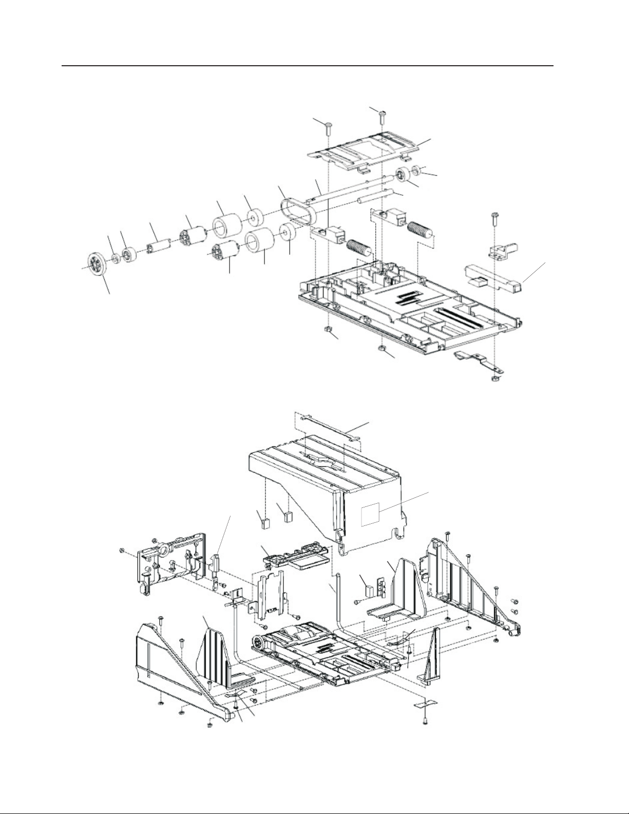
Assembly 23: Platens and Retaining Fences
1 2 3
Updated October 16, 2007
4 5 6
7
56 Self Checkout 4845: Parts Manual Models 131, 15x, 171, 6xx, 8xx, and BW3
Page 69

Updated October 16, 2007
Assembly 23: (continued)
Asm–
Index
Part
Number
Units Description
23– See “How to Use This Parts Manual” on page v for general parts manual
information, including ordering parts. See “Identifying a Right Hand or Left Hand
Model” on page v for how to identify left hand and right hand models.
–1 41D7323 1 Flat platen with 2 bag hole pattern, right hand, Models 152, 602, and 612
– 41D7324 1 Flat platen with 2 bag hole pattern, left hand, Models 152, 602, and 612
||||
–2 41D7636 1 Platen for Models 153, 603, and 613, tiered, 3 bag hole pattern, right hand/left
||||
|
– 41D8184 1 Platen, for Models 151, 606, and 616 Carousel (round platen)
||||
–3 41D7635 1 Platen for Model Models 152, 602, and 612, tiered, 2 bag hole pattern, right hand
||||
– 41D9327 1 Platen for Models 152, 602, and 612, tiered, 2 bag hole pattern, left hand
||||
–4 41J9748 1 Platen, flat, 1 bag hole pattern, right hand/left hand, Model N54
– Platen tower See 26–4 on page 71.
– 41D8196 1 Platen assembly Models 151, 606, and 616 Carousel side shelf
||||
–5 41D7667 1 Platen, flat, Models 152, 602, and 612
||||
–6 41D7669 1 Fence, long retaining, Models 152, 602, and 612 (for use with Models 152, 602,
||||
|
–7 41D7671 1 Fence, short retaining, Models 152, 602, and 612 (for use with Models 152, 602,
||||
|
hand
and 612 flat platen)
and 612 flat platen)
Chapter 2. Load Cells, Platens, Plates, and Retaining Fences 57
Page 70

Assembly 23: (continued)
Updated October 16, 2007
58 Self Checkout 4845: Parts Manual Models 131, 15x, 171, 6xx, 8xx, and BW3
Page 71

Updated October 16, 2007
Chapter 3. Security Conveyor
Assembly 24: Security Conveyor . . . . . . . . . . . . . . . . . .60
© Copyright IBM Corp. 2006, 2007 59
Page 72

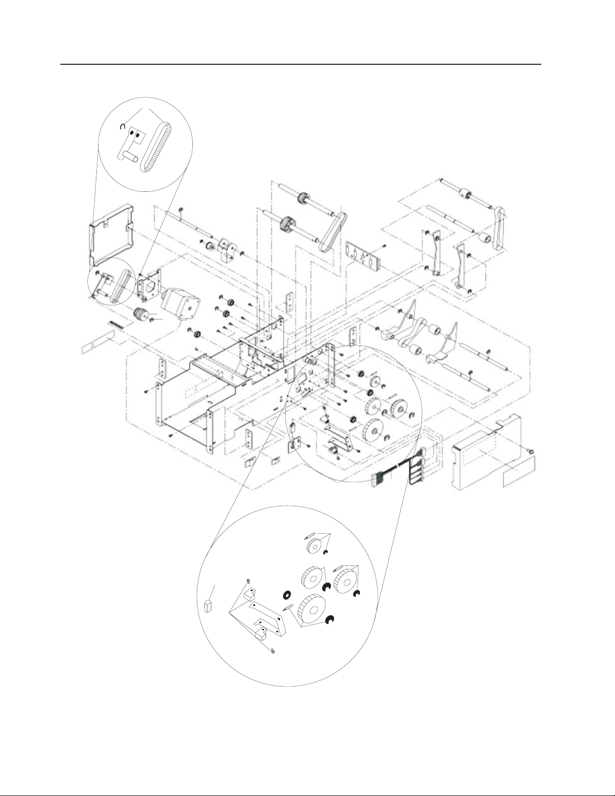
Assembly 24: Security Conveyor
Updated October 16, 2007
23
22
21
24
20
25
19
26
18
17
27
16
15
1
2
3
4
5
6
7
8
14
11
12
10
9
13
28
29
31
31
32
33
30
34
60 Self Checkout 4845: Parts Manual Models 131, 15x, 171, 6xx, 8xx, and BW3
Page 73

Updated October 16, 2007
Assembly 24: (continued)
Asm–
Index
Part
Number
Units Description
24– See “How to Use This Parts Manual” on page v for general parts manual
information, including ordering parts. See “Identifying a Right Hand or Left Hand
Model” on page v for how to identify left hand and right hand models.
– 41J7432 1 Security conveyor assembly, 19 in., 115V
– 41J7436 1 Security conveyor assembly, 19 in., 230V
– 41J7440 1 Security conveyor assembly, 25 in., 115V
– 41J7444 1 Security conveyor assembly, 25 in., 230V
–1 41J8791 1 Skid plate (for standard lane with 19 inch belt)
–1 41J8896 1 Skid plate (for wide lane with 25 inch belt)
–2 41J9127 1 Plate, front transition, with sensors (for standard lane with 19 inch belt)
–2 41J8340 1 Plate, front transition, with sensors (for wide lane with 25 inch belt)
–2 41J8848 1 Plate, front transition (for wide lane with 25 inch belt) (includes support bracket)
–3 41D9782 1 Card stop bracket (mounted under the transition plate) (for standard lane with 19
inch belt)
–3 41J8867 1 Card stop bracket (mounted under the transition plate) (for wide lane with 25 inch
belt)
–4 41J9312 1 Motorized pulley, 19" security conveyor 115V-60hz, balanced
–4 41D9816 1 Motorized pulley, 19" security conveyor 230V-50hz, balanced
–4 41J9320 1 Motorized pulley, 25" security conveyor 115V-60hz, balanced
–4 41D9822 1 Motorized pulley, 25" security conveyor 230V-50hz, balanced
–5 28R3196 1 Guide, tracking, nose end (order with 28R3195). Adhesive plastic sticker. Reduces
friction between belt and metal sides.
–6 28R3298 1 Roller, idler (for standard lane with 19 inch belt)
–6 28R3275 1 Roller, idler (for wide lane with 25 inch belt)
–7 28R3284 2 Angle adjuster (one on each side)
–8 28R3285 2 Drive roller retaining angle (one on each side)
–9 41J7666 2 Bracket, drive isolation. Large black coupling. Use to adjust and isolate motor. (one
on each side)
–10 28R3283 2 Block, idler roller (one on each side)
–11 41J9845 1 Emitter, flat pack sensor assembly, replaces 40M9507, (Flat pack sensor
assemblies for the emitter and detector should be replaced as a set. Order
41J9849 detector.)
–12 41J9845 1 Exit sensor emitter (for standard lane with 19 inch belt)
–12 41J8344 1 Exit sensor emitter (for wide lane with 25 inch belt)
– 41J8854 1 Sensor cable, transition plate (not shown)
–13 41J8850 1 2nd emitter mounting bracket
–14 41D9783 1 Exit sensor mounting bracket
–15 28R3191 1 Plate, conveyer, left side (for standard lane with 19 inch belt)
–15 28R3277 1 Plate, conveyer, left side (for wide lane with 25 inch belt)
–16 28R3194 1 Guide, tracking, motor end (order with 28R3197). Adhesive plastic sticker. Reduces
friction between belt and metal sides.
–17 28R3192 1 Belt, security conveyor, with roller (for standard lane with 19 inch belt)
–17 28R3278 1 Belt, security conveyor, with roller (for wide lane with 25 inch belt)
–18 41J8338 1 Crossbar, conveyor frame (for standard lane with 19 inch belt) Aluminum bar.
(Replaces 28R3180)
–18 28R3279 1 Crossbar, conveyor frame (for wide lane with 25 inch belt)
–19 41J7448 1 Nose bar assembly (for standard lane with 19 inch belt)
–19 41J7450 1 Nose bar assembly (for wide lane with 25 inch belt)
–20 28R3195 1 Guide, tracking, motor end (order with 28R3196). Adhesive plastic sticker. Reduces
friction between belt and metal sides.
–21 28R3190 1 Plate, conveyer, right side (for standard lane with 19 inch belt)
–21 28R3276 1 Plate, conveyer, right side (for wide lane with 25 inch belt)
–22 28R3172 1 Nose bar angle adjuster
Chapter 3. Security Conveyor 61
Page 74

Assembly 24: (continued)
Updated October 16, 2007
Asm–
Index
–23 41J8869 1 2nd detector mounting bracket
–24 41D9783 1 Exit sensor mounting bracket
–25 41J9849 1 Exit sensor detector (for standard lane with 19 inch belt)
–25 41J8342 1 Exit sensor detector (for wide lane with 25 inch belt)
–26 41J9849 1 Detector, flat pack sensor assembly, replaces 40M9508, (Flat pack sensor
Part
Number
Units Description
assemblies for the emitter and detector should be replaced as a set. Order
41J9845 emitter.)
–27 28R3197 1 Guide, tracking, motor end (order with 28R3194). Adhesive plastic sticker. Reduces
friction between belt and metal sides.
– 41J7676 M6 x 19 Black screw for security shield (not shown)
–28 41J7678 2 Security shield
–29 41J9544 1 Capacitor box, 230V
–29 41J9546 1 Capacitor box, 115V
– 40M9423 1 Capacitor box cable (provides power to the conveyor motors) (not shown)
–30 41D9785 1 Curtain support, RH (for standard lane with 19 inch belt)
–30 41D9786 1 Curtain support, RH (for wide lane with 25 inch belt)
–30 41D9803 1 Curtain support, LH (for standard lane with 19 inch belt)
–30 41D9804 1 Curtain support, LH (for wide lane with 25 inch belt)
–32 41D9784 1 Cap, tower (one on each side)
–32 44M2189 1 Curtain detector/emitter sensor assembly (matched set) (located in the curtain
tower)
–33 41D9787 1 Tower, rear curtain support (for standard lane with 19 inch belt)
–33 41D9788 1 Tower, rear curtain support (for wide lane with 25 inch belt)
–34 44M2232 1 Curtain guard, customer side (for wide lane with 25 inch belt)
– 41J8414 4 Cable, curtain sensor fanout dongle (not shown)
– 41J8336 1 Wire cord clips (bag of 10)
– 42H1161 1 Cable tie (not shown)
– NOTE: Hardware items such as screws, bolts, nuts, and washers removed during
the disassembly of parts should be retained for use during re-assembly of those
parts. Screws, bolts, nuts, and washers can not be ordered separately, they are
available as part of a field kit. See Chapter 12, “Field Kits and Tools,” on page 101
for a listing of screws, bolts, nuts, and washers contained in each field kit.
– 41E1748 4 Transition plate extension cable
– 41E1749 2 Sensor extension cable
62 Self Checkout 4845: Parts Manual Models 131, 15x, 171, 6xx, 8xx, and BW3
Page 75

Updated October 16, 2007
Chapter 4. Transport Conveyor
Assembly 25: Transport Conveyor . . . . . . . . . . . . . . . . . .64
© Copyright IBM Corp. 2006, 2007 63
Page 76
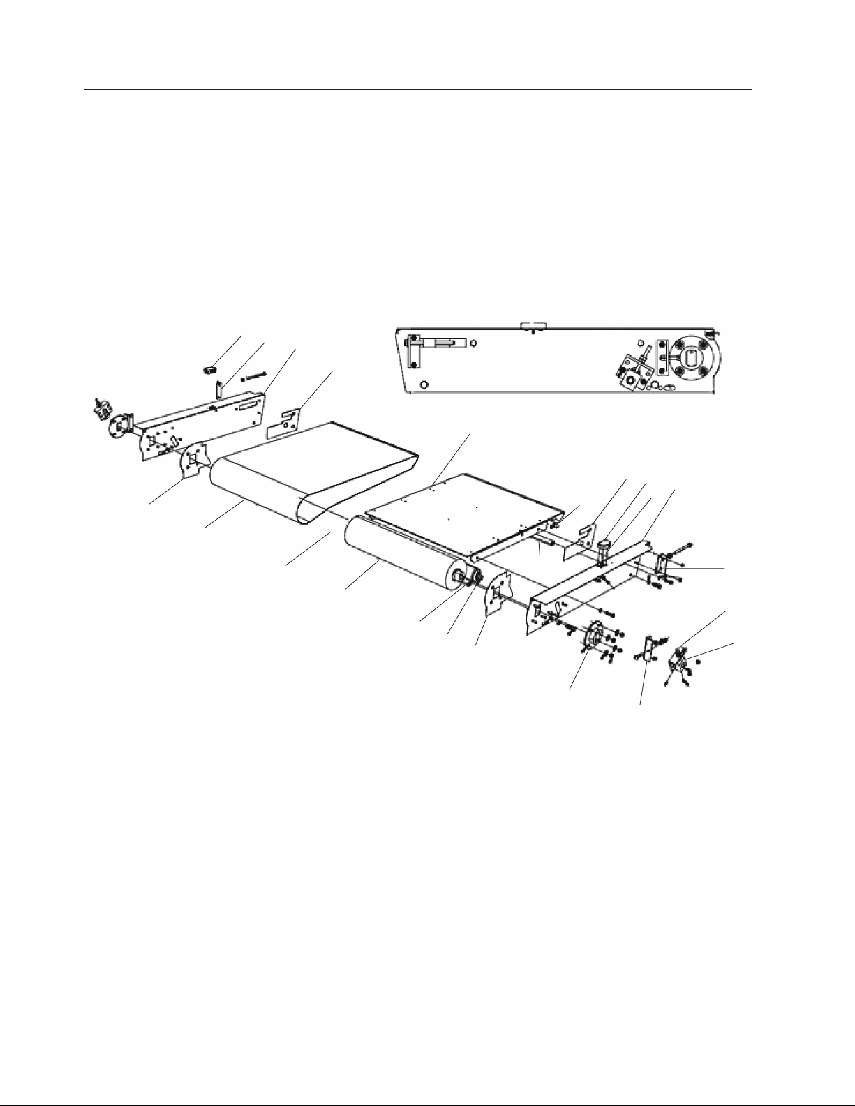
Assembly 25: Transport Conveyor
21
14
20
19
Updated October 16, 2007
18
16
15
13
1
17
14
2
3
4
12
4
11
5
6
10
7
8
9
64 Self Checkout 4845: Parts Manual Models 131, 15x, 171, 6xx, 8xx, and BW3
Page 77

Updated October 16, 2007
Assembly 25: (continued)
Asm–
Index
Part
Number
Units Description
25– See “How to Use This Parts Manual” on page v for general parts manual
information, including ordering parts. See “Identifying a Right Hand or Left Hand
Model” on page v for how to identify left hand and right hand models.
– 41J7434 1 Transport conveyor assembly, 19 in., 115V
– 44M1899 1 Transport conveyor assembly with Sensormatic, 19 in., 115V, right hand
– 44M1900 1 Transport conveyor assembly with Sensormatic, 19 in., 115V, left hand
– 41J7438 1 Transport conveyor assembly, 19 in., 230V
– 41J7442 1 Transport conveyor assembly, 25 in., 115V
– 44D0405 1 Transport conveyor assembly with Sensormatic, 25 in., 115V, right hand
– 44D0407 1 Transport conveyor assembly with Sensormatic, 25 in., 115V, left hand
– 41J7446 1 Transport conveyor assembly, 25 in., 230V
–1 28R3196 1 Guide, tracking, motor end (order with 28R3195). Adhesive plastic sticker.
–2 28R3189 1 Belt, transport conveyor (for standard lane with 19 inch belt)
–2 28R3274 1 Belt, transport conveyor (for wide lane with 25 inch belt)
–3 41D9769 1 LED light visor mount (not shown, located on motor cable)
–4 41J9310 1 Motorized pulley, 19" conveyor 115-60hz, unbalanced (transport only)
–4 41D9818 1 Motorized pulley, 19" transport conveyor 230V
–4 41J9318 1 Motorized pulley, 25" conveyor 115-60hz, unbalanced (transport only)
–4 41D9820 1 Motorized pulley, 25" transport conveyor 230V
–5 41J8438 1 Crossbar, conveyor frame (for standard lane with 19 inch belt)
–5 28R3279 1 Crossbar, conveyor frame (for wide lane with 25 inch belt)
–6 28R3298 1 Roller (for standard lane with 19 inch belt)
–6 28R3275 1 Roller (for wide lane with 25 inch belt)
–7 28R3197 1 Guide, tracking, motor end (order with 28R3194). Adhesive plastic sticker.
–8 41J7666 2 Bracket, drive isolation. Large black coupling. Use to adjust and isolate motor. (one
on each side)
–9 28R3285 2 Drive roller retaining angle (one on each side)
–10 28R3283 2 Block, idler roller (one on each side)
–11 28R3284 2 Bracket, tensioner (one on each side)
–12 28R3172 1 Nosebar adjusting angle
–13 41J7426 1 Plate, side, transport conveyor, left side
–14 41J6928 1 Emitter/detector bracket, bagging area full sensor
–15 41D7146 1 Emitter, bagging area full sensor (for standard lane with 19 inch belt)
–15 41J8450 1 Emitter, bagging area full sensor (for wide lane with 25 inch belt)
–16 28R3195 1 Guide, tracking, motor end (order with 28R3196). Adhesive plastic sticker.
–17 41J7448 1 Assembly, nosebar, (for standard lane with 19 inch belt) (Replaces 28R7098)
–17 41J7450 1 Assembly, nosebar, (for wide lane with 25 inch belt) (Replaces 28R7084)
–18 41J8332 1 Skid plate, (for standard lane with 19 inch belt), no Sensormatic
–18 44M1913 1 Skid plate with Sensormatic opening, (for standard lane with 19 inch belt), right
hand
–18 44M1914 1 Skid plate with Sensormatic opening, (for standard lane with 19 inch belt), left hand
–18 41J8334 1 Skid plate, (for wide lane with 25 inch belt), no Sensormatic
–19 28R3194 1 Guide, tracking, motor end (order with 28R3197). Adhesive plastic sticker.
–20 41J7425 1 Plate, side, transport conveyor, right side plate
–21 41D7150 1 Detector, bagging area full sensor (for standard lane with 19 inch belt)
–21 41J8452 1 Detector, bagging area full sensor (for wide lane with 25 inch belt)
– 41J7126 1 25 inch order separator (not shown). See 42–1 on page 121.
– 41J7127 1 19 inch order separator (not shown). See 42–1 on page 121.
– 41J8854 1 Sensor cable, transition plate (not shown)
– 41J8855 1 Transition plate emitter (not shown)
– 41J8856 1 Transition plate detector (not shown)
– 42H1161 1 Cable tie (not shown)
– 41J8336 1 Wire cord clips (bag of 10)
Chapter 4. Transport Conveyor 65
Page 78

Assembly 25: (continued)
Updated October 16, 2007
Asm–
Index
– NOTE: Hardware items such as screws, bolts, nuts, and washers removed during
Part
Number
Units Description
the disassembly of parts should be retained for use during re-assembly of those
parts. Screws, bolts, nuts, and washers can not be ordered separately, they are
available as part of a field kit. See Chapter 12, “Field Kits and Tools,” on page 101
for a listing of screws, bolts, nuts, and washers contained in each field kit.
66 Self Checkout 4845: Parts Manual Models 131, 15x, 171, 6xx, 8xx, and BW3
Page 79

Updated October 16, 2007
Chapter 5. Bagging and Carousel Bagging
© Copyright IBM Corp. 2006, 2007 67
Page 80

Updated October 16, 2007
Assembly 26: Carousel parts . . . . . . . . . . . . . . . . . . . .70
A
C
B
D
E
F
Figure 2. Self Checkout bagging options
68 Self Checkout 4845: Parts Manual Models 131, 15x, 171, 6xx, 8xx, and BW3
Page 81

Updated October 16, 2007
Contact your IBM parts center for bagging parts. Be sure to have the correct model
name and store name when ordering parts. See “How to Use This Parts Manual” on
page v for general parts manual information, including ordering parts. See
“Identifying a Right Hand or Left Hand Model” on page v for how to identify left
hand and right hand models.
The bagging options are:
Table 1.
Key Description
||
||
|
||
A Model 131, bagging rack attached to the core module
B Models 151, 606, and 616, 6 bagging stations on a carousel
C Models 152, 602, and 612, 2 bagging stations
D Models 153, 603, and 613, 3 bagging stations
E Model N54 Express-Plus, 1 bagging station
||
|
F Models 171, 800, and 810 Full Lane, a transport conveyor that delivers items
to a bagging area
Chapter 5. Bagging and Carousel Bagging 69
Page 82

Assembly 26: Carousel parts
Updated October 16, 2007
4
3
2
5
1
6
7
10
9
8
70 Self Checkout 4845: Parts Manual Models 131, 15x, 171, 6xx, 8xx, and BW3
Page 83

Updated October 16, 2007
Assembly 26: (continued)
Asm–
Index
Part
Number
Units Description
26–1 1 Load cell. See 22–1 on page 55.
–2 Platen, carousel side shelf. See assembly 23– on page 57.
–3 41D9744 1 Carousel bag pack clamping plate
–4 41D8195 1 Lid tower, Models 151, 606, and 616 Carousel, round small
||||
– 41D7621 1 Carousel assembly contains:
–5 v Platen, carousel round. See 23– on page 57.
–6 v Load cell, carousel. See 22–1 on page 55.
–7 41D8194 1 v Wheel assembly Models 151, 606, and 616 carousel, plastic
||||
–8 44M1975 1 Kickplate, front/rear, for Models 151, 606, and 616 carousel
||||
–9 44M1976 1 Kickplate, side, for Models 151, 606, and 616 carousel
||||
–10 44M1977 1 Kickplate, shelf, for Models 151, 606, and 616 carousel
||||
– 41D8185 1 Lower bushing kit, Models 151, 606, and 616 carousel (not shown)
||||
– 41D8187 1 Carousel parts kit, contains - 4 M8x10 hex socket screws, 4 rubber buffers
30x25xM8, 1 grounding spring, 4 shims frolic 1026D, 4 Phil pan head screws NC
6x1", 8 M6x35 hex socket screws, 1 bearing, 8 socket head shoulder screws (M8),
1 upper bushing, 1 nylon locking nut, 1 plastic plug transparent
– 41D8190 1 Electrical interface box for Models 151, 606, and 616 carousel (not shown)
||||
– 41D8192 1 Cable, Models 151, 606, and 616 carousel data communication (not shown)
||||
– 41D8193 1 Power supply Models 151, 606, and 616 carousel, 120/9V external (not shown)
||||
Chapter 5. Bagging and Carousel Bagging 71
Page 84

Assembly 26: (continued)
Updated October 16, 2007
72 Self Checkout 4845: Parts Manual Models 131, 15x, 171, 6xx, 8xx, and BW3
Page 85

Updated October 16, 2007
Chapter 6. Wire Bag Rack
Assembly 27: Wire Bag Rack . . . . . . . . . . . . . . . . . . .74
© Copyright IBM Corp. 2006, 2007 73
Page 86

Assembly 27: Wire Bag Rack
Updated October 16, 2007
12
3
74 Self Checkout 4845: Parts Manual Models 131, 15x, 171, 6xx, 8xx, and BW3
Page 87

Updated October 16, 2007
Assembly 27: (continued)
Asm–
Index
Part
Number
Units Description
27–1 28R3173 (28R3167) Tall rack
–2 28R5540 (28R5697) Short rack
–3 41K7093 (41K7092) European rack
– 41D8560 (41D8559) Rack clamp (not shown)
Chapter 6. Wire Bag Rack 75
Page 88

Assembly 27: (continued)
Updated October 16, 2007
76 Self Checkout 4845: Parts Manual Models 131, 15x, 171, 6xx, 8xx, and BW3
Page 89

Updated October 16, 2007
Chapter 7. BOSS
Assembly 28: BOSS FRUs . . . . . . . . . . . . . . . . . . . .78
© Copyright IBM Corp. 2006, 2007 77
Page 90

Assembly 28: BOSS FRUs
Updated October 16, 2007
78 Self Checkout 4845: Parts Manual Models 131, 15x, 171, 6xx, 8xx, and BW3
Page 91

Updated October 16, 2007
Assembly 28: (continued)
Asm–
Index
Part
Number
Units Description
28– 23K8035 1 Cover, I/O blank
– 41A3391 1 Riser card, 2 PCI slots
– Lane PC. See “Assembly 21: Lane PC, Mouse, and Keyboard” on page 50.
Monitor/display. See 1–4 on page 3.
Magnetic stripe reader. See 1–5 on page 3.
Power strip. See 1–37 on page 4.
Power supply. See 1–34 on page 4.
Printer. See “Assembly 12: Printers TIx and TGx” on page 28.
Chapter 7. BOSS 79
Page 92

Assembly 28: (continued)
Updated October 16, 2007
80 Self Checkout 4845: Parts Manual Models 131, 15x, 171, 6xx, 8xx, and BW3
Page 93

Updated October 16, 2007
Chapter 8. Integrated Paystation
Assembly 29: Paystation . . . . . . . . . . . . . . . . . . . . .82
© Copyright IBM Corp. 2006, 2007 81
Page 94

Assembly 29: Paystation
Updated October 16, 2007
1
2
2
82 Self Checkout 4845: Parts Manual Models 131, 15x, 171, 6xx, 8xx, and BW3
5
3
4
Page 95

Updated October 16, 2007
Assembly 29: (continued)
Asm–
Index
Part
Number
Units Description
29– 41D8116 1 Stabilizer, paystation front/rear (not shown)
– 41D8118 1 Stabilizer, paystation side (not shown)
–1 41D7391 1 Paystation shelf
–2 41D7320 1 Integrated Paystation interface plate/cable cover
–3 44D0861 1 Integrated Paystation front/rear kickplate
–4 44D0862 1 Integrated Paystation left/right side kickplate
–5 1 Keylock, cabinet lock with key. See Chapter 11 , “Locks and Keys,” on page 95.
Chapter 8. Integrated Paystation 83
Page 96

Assembly 29: (continued)
Updated October 16, 2007
84 Self Checkout 4845: Parts Manual Models 131, 15x, 171, 6xx, 8xx, and BW3
Page 97

Updated October 16, 2007
Chapter 9. EPO (Red) Button
Assembly 30: EPO (Red) Button . . . . . . . . . . . . . . . . . .86
© Copyright IBM Corp. 2006, 2007 85
Page 98

Assembly 30: EPO (Red) Button
Updated October 16, 2007
1
2
86 Self Checkout 4845: Parts Manual Models 131, 15x, 171, 6xx, 8xx, and BW3
Page 99

Updated October 16, 2007
Assembly 30: (continued)
Asm–
Index
Part
Number
Units Description
30–1 41K7082 1 EPO button (red) button cable assembly (EPO button mounted on top of upper core
module door for certain customers)
–2 41K7080 1 Reset (green) and EPO (red) buttons Y cable (used with 41K7082 instead of
40M9470 1–2 on page 3)
Chapter 9. EPO (Red) Button 87
Page 100

Assembly 30: (continued)
Updated October 16, 2007
88 Self Checkout 4845: Parts Manual Models 131, 15x, 171, 6xx, 8xx, and BW3
 Loading...