

Page 1

Managing Devices for the
M6-700 or M7-700
ESCALA Power7
REFERENCE
86 A1 84FF 00
Page 2

Page 3

ESCALA Power7
Managing Devices for the M6-700
or M7-700
This publication concerns the following models:
- Bull Escala E5-700 (Power 750 / 8233-E8B)
- Bull Escala M6-700 (Power 770 / 9117-MMB)
- Bull Escala M7-700 (Power 780 / 9179-MHB)
References to Power 755 / 8236-E8C models are irrelevant.
Hardware
March 2010
BULL CEDOC
357 AVENUE PATTON
B.P.20845
49008 ANGERS CEDEX 01
FRANCE
REFERENCE
86 A1 84FF 00
Page 4

The following copyright notice protects this book under Copyright laws which prohibit such actions as, but not limited
to, copying, distributing, modifying, and making derivative works.
Copyright
Suggestions and criticisms concerning the form, content, and presentation of this
book are invited. A form is provided at the end of this book for this purpose.
To order additional copies of this book or other Bull Technical Publications, you
are invited to use the Ordering Form also provided at the end of this book.
Bull SAS 2007-2010
Printed in France
Trademarks and Acknowledgements
We acknowledge the right of proprietors of trademarks mentioned in this book.
The information in this document is subject to change without notice. Bull will not be liable for errors
ontained herein, or for incidental or consequential damages in connection with the use of this material.
c
Page 5

Contents
Safety notices .................................v
Chapter 1. What’s new in Managing devices ....................1
Chapter 2. Managing tape drives .........................3
Tape drives ....................................3
Tape drive media ..................................5
Preparing the tape drive for installation ..........................9
800/1600 GB Ultrium 4 SAS tape drive (FC 5746).......................10
Eject button functions on the tape drive (FC 5746) .....................11
Status lights (FC 5746) ...............................12
Tape cartridges (FC 5746) ..............................14
Setting the write-protect switch (FC 5746) ........................15
Cleaning the tape drive (FC 5746) ...........................15
Maintenance mode (FC 5746) ............................16
Resetting the tape drive ..............................18
Performing the internal self-test (FC 5746) ........................18
200/400 GB Half High Ultrium 2 tape drive (FC 5755) .....................20
Cleaning the tape drive (FC 5755) ...........................20
Setting the write-protect switch (FC 5755) ........................21
Status lights (FC 5755) ...............................22
Tape cartridges (FC 5755) ..............................25
Resetting the tape drive (FC 5755) ...........................26
Performing the internal self-test (FC 5755) ........................26
160/320 GB internal tape drive VXA-320 (FC 6279) ......................28
Cleaning the tape drive (FC 6120 and 6279)........................29
Loading and unloading cartridges ...........................30
Loading a cartridge...............................30
Unloading a cartridge ..............................30
Setting the write-protect switch (FC 6279) ........................30
Status lights (FC 6279) ...............................31
Performing the internal self-test (FC 6120 or 6279) .....................33
Tape cartridges (FC 6279) ..............................34
Resetting the tape drive ..............................35
80/160 GB internal tape drive VXA-2 (FC 6120) .......................35
Cleaning the tape drive (FC 6120 and 6279)........................36
Loading and unloading cartridges ...........................37
Loading a cartridge...............................37
Unloading a cartridge ..............................37
Setting the write-protect switch (FC 6120) ........................38
Status lights (FC 6120) ...............................38
Performing the internal self-test (FC 6120 or 6279) .....................40
Tape cartridges (FC 6120) ..............................41
Resetting the tape drive ..............................42
60/150 GB 16-bit 8-mm internal tape drive (FC 6134) .....................43
Cleaning the tape drive (FC 6134) ...........................43
Loading and unloading cartridges ...........................45
Loading a cartridge...............................45
Unloading a cartridge ..............................45
Setting the write-protect switch (FC 6134) ........................45
Status lights (FC 6134) ...............................46
Tape cartridges (FC 6134) ..............................47
Resetting the tape drive ..............................48
36/72 GB Data72 4 mm internal tape drive (FC 6258 or 5907)...................48
Cleaning the tape drive (FC 6258 or 5907) ........................49
© Copyright IBM Corp. 2010 iii
Page 6

Loading and unloading cartridges ...........................50
Loading a cartridge...............................50
Unloading a cartridge ..............................51
Setting the write-protect switch (FC 6258 or 5907) .....................51
Status lights (FC 6258 or 5907) ............................52
Tape cartridges (FC 6258 or 5907) ...........................54
Resetting the tape drive ..............................54
80/160 GB DAT160 SAS Tape Drive (FC 5619) ........................54
Cleaning the tape drive (FC 5619) ...........................55
Loading and unloading cartridges ...........................57
Loading a cartridge...............................57
Unloading a cartridge ..............................57
Setting the write-protect switch (FC 5619) ........................57
Status lights (FC 5619) ...............................58
Tape cartridges (FC 5619) ..............................60
Resetting the tape drive ..............................60
160/320 GB DAT320 SAS Tape Drive (FC 5661) .......................61
Cleaning the tape drive (FC 5661) ...........................62
Loading and unloading cartridges ...........................63
Loading a cartridge...............................63
Unloading a cartridge ..............................63
Setting the write-protect switch (FC 5661) ........................64
Status lights (FC 5661) ...............................64
Tape cartridges (FC 5661) ..............................67
Resetting the tape drive ..............................68
Chapter 3. Managing DVD drives ........................69
SATA Slimline DVD-RAM Drive (FC 5762) .........................69
Handling and storing the DVD media ..........................69
Opening a DVD tray manually .............................70
DVD-RAM type II disc ...............................70
Chapter 4. Managing diskette drives .......................73
External USB 1.44 MB diskette drive (FC 2591) .......................73
Chapter 5. Managing disk devices ........................75
Chapter 6. Managing removable disk drives ....................77
USB Removable Disk Drive (FC 1103, 1104, 1106, 1107) .....................77
Chapter 7. Managing communications devices ..................83
LAN-Attached Remote Asynchronous Node 16 (model 7036-P16) .................83
7036-P16 description and overview ..........................83
Installing 7036-P16 hardware ............................85
Installing Digi RealPort software for the 7036-P16 device ...................86
Configuring the 7036-P16 device and tty.........................88
Configuring the 7036-P16 into the network ........................90
Using diagnostic aids for the 7036-P16 .........................93
Replacing and reconfiguring the 7036-P16 ........................94
Field replacement units for the 7036-P16 .........................97
Appendix. Notices ...............................99
Trademarks ...................................100
Electronic emission notices ..............................100
Class A Notices.................................100
Terms and conditions................................104
iv Power Systems: Managing devices
Page 7

Safety notices
Safety notices may be printed throughout this guide:
v DANGER notices call attention to a situation that is potentially lethal or extremely hazardous to
people.
v CAUTION notices call attention to a situation that is potentially hazardous to people because of some
existing condition.
v Attention notices call attention to the possibility of damage to a program, device, system, or data.
World Trade safety information
Several countries require the safety information contained in product publications to be presented in their
national languages. If this requirement applies to your country, a safety information booklet is included
in the publications package shipped with the product. The booklet contains the safety information in
your national language with references to the U.S. English source. Before using a U.S. English publication
to install, operate, or service this product, you must first become familiar with the related safety
information in the booklet. You should also refer to the booklet any time you do not clearly understand
any safety information in the U.S. English publications.
German safety information
Das Produkt ist nicht für den Einsatz an Bildschirmarbeitsplätzen im Sinne§2der
Bildschirmarbeitsverordnung geeignet.
Laser safety information
IBM®servers can use I/O cards or features that are fiber-optic based and that utilize lasers or LEDs.
Laser compliance
IBM servers may be installed inside or outside of an IT equipment rack.
© Copyright IBM Corp. 2010 v
Page 8

DANGER
When working on or around the system, observe the following precautions:
Electrical voltage and current from power, telephone, and communication cables are hazardous. To
avoid a shock hazard:
v Connect power to this unit only with the IBM provided power cord. Do not use the IBM
provided power cord for any other product.
v Do not open or service any power supply assembly.
v Do not connect or disconnect any cables or perform installation, maintenance, or reconfiguration
of this product during an electrical storm.
v The product might be equipped with multiple power cords. To remove all hazardous voltages,
disconnect all power cords.
v Connect all power cords to a properly wired and grounded electrical outlet. Ensure that the outlet
supplies proper voltage and phase rotation according to the system rating plate.
v Connect any equipment that will be attached to this product to properly wired outlets.
v When possible, use one hand only to connect or disconnect signal cables.
v Never turn on any equipment when there is evidence of fire, water, or structural damage.
v Disconnect the attached power cords, telecommunications systems, networks, and modems before
you open the device covers, unless instructed otherwise in the installation and configuration
procedures.
v Connect and disconnect cables as described in the following procedures when installing, moving,
or opening covers on this product or attached devices.
To Disconnect:
1. Turn off everything (unless instructed otherwise).
2. Remove the power cords from the outlets.
3. Remove the signal cables from the connectors.
4. Remove all cables from the devices
To Connect:
1. Turn off everything (unless instructed otherwise).
2. Attach all cables to the devices.
3. Attach the signal cables to the connectors.
4. Attach the power cords to the outlets.
5. Turn on the devices.
(D005)
DANGER
vi Power Systems: Managing devices
Page 9

Observe the following precautions when working on or around your IT rack system:
v Heavy equipment–personal injury or equipment damage might result if mishandled.
v Always lower the leveling pads on the rack cabinet.
v Always install stabilizer brackets on the rack cabinet.
v To avoid hazardous conditions due to uneven mechanical loading, always install the heaviest
devices in the bottom of the rack cabinet. Always install servers and optional devices starting
from the bottom of the rack cabinet.
v Rack-mounted devices are not to be used as shelves or work spaces. Do not place objects on top
of rack-mounted devices.
v Each rack cabinet might have more than one power cord. Be sure to disconnect all power cords in
the rack cabinet when directed to disconnect power during servicing.
v Connect all devices installed in a rack cabinet to power devices installed in the same rack
cabinet. Do not plug a power cord from a device installed in one rack cabinet into a power
device installed in a different rack cabinet.
v An electrical outlet that is not correctly wired could place hazardous voltage on the metal parts of
the system or the devices that attach to the system. It is the responsibility of the customer to
ensure that the outlet is correctly wired and grounded to prevent an electrical shock.
CAUTION
v Do not install a unit in a rack where the internal rack ambient temperatures will exceed the
manufacturer’s recommended ambient temperature for all your rack-mounted devices.
v Do not install a unit in a rack where the air flow is compromised. Ensure that air flow is not
blocked or reduced on any side, front, or back of a unit used for air flow through the unit.
v Consideration should be given to the connection of the equipment to the supply circuit so that
overloading of the circuits does not compromise the supply wiring or overcurrent protection. To
provide the correct power connection to a rack, refer to the rating labels located on the
equipment in the rack to determine the total power requirement of the supply circuit.
v (For sliding drawers.) Do not pull out or install any drawer or feature if the rack stabilizer brackets
are not attached to the rack. Do not pull out more than one drawer at a time. The rack might
become unstable if you pull out more than one drawer at a time.
v (For fixed drawers.) This drawer is a fixed drawer and must not be moved for servicing unless
specified by the manufacturer. Attempting to move the drawer partially or completely out of the
rack might cause the rack to become unstable or cause the drawer to fall out of the rack.
(R001)
Safety notices vii
Page 10

CAUTION:
Removing components from the upper positions in the rack cabinet improves rack stability during
relocation. Follow these general guidelines whenever you relocate a populated rack cabinet within a
room or building:
v Reduce the weight of the rack cabinet by removing equipment starting at the top of the rack
cabinet. When possible, restore the rack cabinet to the configuration of the rack cabinet as you
received it. If this configuration is not known, you must observe the following precautions:
– Remove all devices in the 32U position and above.
– Ensure that the heaviest devices are installed in the bottom of the rack cabinet.
– Ensure that there are no empty U-levels between devices installed in the rack cabinet below the
32U level.
v If the rack cabinet you are relocating is part of a suite of rack cabinets, detach the rack cabinet from
the suite.
v Inspect the route that you plan to take to eliminate potential hazards.
v Verify that the route that you choose can support the weight of the loaded rack cabinet. Refer to the
documentation that comes with your rack cabinet for the weight of a loaded rack cabinet.
v Verify that all door openings are at least 760 x 230 mm (30 x 80 in.).
v Ensure that all devices, shelves, drawers, doors, and cables are secure.
v Ensure that the four leveling pads are raised to their highest position.
v Ensure that there is no stabilizer bracket installed on the rack cabinet during movement.
v Do not use a ramp inclined at more than 10 degrees.
v When the rack cabinet is in the new location, complete the following steps:
– Lower the four leveling pads.
– Install stabilizer brackets on the rack cabinet.
– If you removed any devices from the rack cabinet, repopulate the rack cabinet from the lowest
position to the highest position.
v If a long-distance relocation is required, restore the rack cabinet to the configuration of the rack
cabinet as you received it. Pack the rack cabinet in the original packaging material, or equivalent.
Also lower the leveling pads to raise the casters off of the pallet and bolt the rack cabinet to the
pallet.
(R002)
(L001)
(L002)
viii Power Systems: Managing devices
Page 11

(L003)
or
All lasers are certified in the U.S. to conform to the requirements of DHHS 21 CFR Subchapter J for class
1 laser products. Outside the U.S., they are certified to be in compliance with IEC 60825 as a class 1 laser
product. Consult the label on each part for laser certification numbers and approval information.
CAUTION:
This product might contain one or more of the following devices: CD-ROM drive, DVD-ROM drive,
DVD-RAM drive, or laser module, which are Class 1 laser products. Note the following information:
v Do not remove the covers. Removing the covers of the laser product could result in exposure to
hazardous laser radiation. There are no serviceable parts inside the device.
v Use of the controls or adjustments or performance of procedures other than those specified herein
might result in hazardous radiation exposure.
(C026)
Safety notices ix
Page 12

CAUTION:
Data processing environments can contain equipment transmitting on system links with laser modules
that operate at greater than Class 1 power levels. For this reason, never look into the end of an optical
fiber cable or open receptacle. (C027)
CAUTION:
This product contains a Class 1M laser. Do not view directly with optical instruments. (C028)
CAUTION:
Some laser products contain an embedded Class 3A or Class 3B laser diode. Note the following
information: laser radiation when open. Do not stare into the beam, do not view directly with optical
instruments, and avoid direct exposure to the beam. (C030)
Power and cabling information for NEBS (Network Equipment-Building System)
GR-1089-CORE
The following comments apply to the IBM servers that have been designated as conforming to NEBS
(Network Equipment-Building System) GR-1089-CORE:
The equipment is suitable for installation in the following:
v Network telecommunications facilities
v Locations where the NEC (National Electrical Code) applies
The intrabuilding ports of this equipment are suitable for connection to intrabuilding or unexposed
wiring or cabling only. The intrabuilding ports of this equipment must not be metallically connected to the
interfaces that connect to the OSP (outside plant) or its wiring. These interfaces are designed for use as
intrabuilding interfaces only (Type 2 or Type 4 ports as described in GR-1089-CORE) and require isolation
from the exposed OSP cabling. The addition of primary protectors is not sufficient protection to connect
these interfaces metallically to OSP wiring.
Note: All Ethernet cables must be shielded and grounded at both ends.
The ac-powered system does not require the use of an external surge protection device (SPD).
The dc-powered system employs an isolated DC return (DC-I) design. The DC battery return terminal
shall not be connected to the chassis or frame ground.
x Power Systems: Managing devices
Page 13

Chapter 1. What’s new in Managing devices
See what is new and what has changed in Managing devices since the last edition of this topic.
March 2010
v Added information on Handling and storing the DVD media.
February 2010
v Added information for IBM Power Systems™servers that contain the POWER7™processor.
© Copyright IBM Corp. 2010 1
Page 14

2 Power Systems: Managing devices
Page 15

Chapter 2. Managing tape drives
Learn about using and managing removable media devices. Find specifications and installation notes for
specific drives.
Tape drives
Learn general information about tape drives.
Select the appropriate information from this list:
v Tape drive overview
v Tape drive environment and use
v Tape handling and storage
v Environmental issues
v Tape drive cleaning
v SCSI hardware issues
v Microcode updates
Tape drive overview
Your tape drive must be installed in the cleanest possible environment. Additionally, tape drives require
high quality, data grade tapes and cleaning on a regular basis. Media must also be stored and handled
properly. Improper use, storage or handling of tape drives or media may void your warranty or service
agreement. If a tape drive stops functioning due to a component failure during the tape drive warranty
or maintenance time, the tape drive supplier will replace the tape drive unit. The tape drive supplier will
replace any defective tape drive under the terms and conditions of the warranty or service agreement.
The tape drive is a streaming device used primarily for:
v Saving and restoring system data files
v Archiving important records
v Distributing operating system software upgrades
Note: The following information describes hardware features and functions. While the hardware
supports them, the availability of these features and functions depends upon support from the operating
system. For information about support for features and functions, see the documentation for your
operating system.
Tape drive environment and use
Tape drives require specific maintenance and environmental conditions to operate well over time. Using
high-quality, data-grade media, handling and storing this media correctly, operating the tape drive in a
clean environment, and keeping the tape drive correctly cleaned can help you to avoid problems with
your tape drive.
If a tape drive stops functioning due to a component failure during the tape drive warranty or
maintenance time, the service provider will replace the tape drive unit. The service provider will replace
any defective tape drive under the terms and conditions of its warranty or service agreement. It is the
service provider’s objective to work with you to identify the cause of any tape-drive problem and provide
a solution.
© Copyright IBM Corp. 2010 3
Page 16

Tape handling and storage
Most tape is supplied in a sealed cartridge so that the tape will remain clean. Opening the cartridge
allows dirt and airborne particles to enter and then become a source of contamination. The cartridge
should only be opened by the tape drive and not an operator. The tape also is held under proper tension
inside the cartridge. If the cartridge is dropped, this tension will be relaxed.
Attention: Inserting a dropped cartridge into a tape drive can cause incorrect loading and result in a
jam. This action will ruin the tape and can cause physical damage if the cartridge is not removed
correctly.
When the tapes are stored, they must be replaced in their protective containers and stored on their end.
The storage area must be clean, dry, at normal room temperature, and away from any magnetic fields.
Improper use, storage, or handling of tape drives or media might void your warranty or service
agreement.
Environmental issues
Tape drives are designed to operate in a clean environment. Problems can be caused by dirt, dust, fibers,
and airborne particles. Airborne particles are the most difficult to address. When a tape is installed into
the tape drive, the clearance between the heads and the tape is measured in microns. Particles can
damage the tape or the head if they come in contact with either. Customers are responsible to provide a
clean operating environment for the tape drive and system.
Tape drive cleaning
No matter how clean the environment, debris can build up on the heads of any tape drive. Every time
tape motion occurs, some of the media surface comes off on the heads. Over time, this surface builds up
and causes errors in reading and writing. Customers are responsible to clean the tape drive in accordance
with the cleaning information that was provided with the tape drive.
Cleaning cartridges can be used a limited number of times. After a cleaning cartridge has been used to its
maximum number of times, the cartridge is considered expired. When cartridges expire, they must be
replaced. Never reuse an expired cleaning cartridge. Doing so allows previously removed dirt to be
reintroduced to the tape drive. Place a mark on the cleaning cartridge after each use, to best determine
when your cleaning cartridge has expired.
SCSI hardware issues
Note: If you are installing the auto-docking version of this device on your system, this section does not
apply to your system. For information about the auto-docking feature, see your system documentation.
SCSI bus cables and terminators can affect tape drive performance. Use cables and terminators that are
designed specifically to keep the SCSI bus as free of noise as possible. Generic cables or terminators can
adversely affect the SCSI bus performance. If your service provider’s analysis indicates a problem with
inferior cables, it might be necessary for the customer to replace them.
Microcode updates
To make certain that the tape drives work their best, your system supplier might release changed
microcode for the tape drives. When a microcode change is developed, your system supplier makes the
change available to you through its service organization or by electronic delivery. You might be
responsible for installing new microcode as it becomes available. However, microcode can be installed by
your service provider or your system administrator. For more information, contact your authorized
service provider.
4 Power Systems: Managing devices
Page 17

Tape drive media
Learn about using the different types of tape drive media.
Attention: Your system supplier might support only the media that it sells. If the supplier’s analysis
indicates that the problem is caused by using inferior media, it is the customer’s responsibility to replace
the inferior media.
Select the appropriate information from this list:
v Types of cartridges
v Recommendations for data cartridge usage
v Prolonging head life
v Storage and shipping environments
v Tape cartridge storage
v Operating in harsh environments
v Ordering tape cartridges
Types of cartridges
Tape devices use the following media cartridges.
Data cartridge
Use the data cartridge to save or restore programs or data.
Test cartridge
Use the specially labeled test cartridge to run the AIX
running diagnostics, refer to your AIX documentation). Do not use the test cartridge to save or
restore customer programs or data.
Cleaning cartridge
Use the specially labeled cleaning cartridge to clean the device.
Attention: Use of other than the IBM specified cleaning cartridge can damage your device and
might void your warranty.
To order additional cartridges, refer to Ordering tape cartridges.
®
system diagnostics (for information about
Recommendations for data cartridge usage
The following list describes recommended guidelines that will help to protect your data and prolong the
life of your tape cartridges and the device:
v Use only the tape cartridge specified for your type of tape device.
v Remove the tape cartridge from the drive when the drive is not in use.
v Back up and then discard any tape cartridge that repeatedly produces error messages (the error
information is in the System Error Log).
v On the data cartridge, do not open the door that covers the tape. The door protects the tape from dirt,
dust, and damage.
v Do not touch the tape. Any substance transferred to the tape by touching could cause loss of data.
v To avoid problems with loading and unloading, use only one label on a cartridge. Multiple or poorly
placed labels can clog the drive load mechanism.
v Do not use poor-quality tape cartridges. They can cause excessive read or write errors, and they might
damage the tape drive.
v Discard any tape cartridges that are dropped, because the impact might damage the tape’s internal
mechanism.
Chapter 2. Managing tape drives 5
Page 18

v Make sure the environment is kept clean and constant. Do not operate in a dusty environment and
always maintain a constant environment. A consistent storage and operating environment reduces
media exposure to climatic stress.
v Use only the recommended cleaning cartridge to clean the tape drive. Use of other than recommended
cleaning cartridges can damage your drive and might void the warranty.
v Printers and copiers can produce paper dust and toner dust. Locate the tape unit away from these
items. High traffic areas near hallways and doors can also produce excess dust and dirt.
v Record all important information on the tape label. Information, such as the model and number of the
system or tape drive, the date, the density, any error statistics, and include a log number. Also note the
operating environment and compression mode.
Prolonging head life
New technology found in the tape device is read and write compatible with newer tape cartridges. Due
to media characteristics, extended use of older tape cartridges might increase head wear on the drive. An
indication of this head wear is an increase in soft (recoverable) errors. Using newer tape cartridges may
have enhanced characteristics that can reduce drive head wear and maximize the overall advantages of
the tape device.
Storage and shipping environments
Before using a tape cartridge, let it acclimatize to the operating environment by placing the cartridge in
the operating environment for as long as it has been away from the environment or for 24 hours,
whichever is less. Acclimatization is necessary for any data cartridge exposed to an environmental change
in humidity or to temperature changes of 11°C (20°F) or more. To determine the appropriate operating
environment, see Tape drive environment and use.
Retrieval of archived data can be performed on a tape unit that is clean and fully operational. Try to
make the recovery environment the same as the operating environment. Allow tapes at least 24 hours to
acclimatize to the environment of the tape unit.
The recommended environment for storage and shipment of cartridges is shown in Table 1.
Table 1. Recommended environment for data cartridges
Environmental Factor Storage Shipping
Temperature 5°C to 32°C
(41° to 90°F)
Relative Humidity
(noncondensing)
Maximum Wet Bulb 26°C
20 to 60% 5 to 80%
(79°F)
-40 to 52°C
(-40 to 125°F)
26°C
(79°F)
Tape cartridge storage
Tape drives record data using densities similar to hard disk drives. Because most computer systems are
not located in a dust-free, climate-controlled environment, you must exercise special care when dealing
with tape cartridges and tape drives. They must be treated as a valuable asset used to protect your
business data.
Use the following guidelines for storing your tape cartridges:
v Keep temperature and humidity constant at the levels listed in Table 1.
6 Power Systems: Managing devices
Page 19

v Always store tape cartridges in their protective cases. The storage case helps prevent damage from dust
and physical misuse. When the tape cartridges are not in use or being stored, keep them in their
storage cases and stand on edge in a designated storage location. Do not stack cartridges on the flat
side or stack other items on top of the tape cartridges. Handle your tape cartridges with care to reduce
archival problems.
v Keep protective cases for tape cartridges closed except when inserting or removing a cartridge.
Contamination can build up and be transferred to the tape cartridge if the protective case is left open.
v Exercise stored tapes at least once every 12 months. Run the tape from Beginning of Data (BOD) to
End of Data (EOD) and back to BOD at normal operating speeds. Exercise tapes stored in a warmer
environment more frequently.
v Sunlight can damage the tape and the cartridge shell. Store tape cartridges out of the direct sunlight.
Attention: Operation outside of the recommended environment can result in possible loss of data or
failure of the drive.
Operating in harsh environments
The device is suited to streaming operations, as opposed to multiple stop-and-start, random-search tape
operations. When the tape is used for frequent stop-and-start operations, it is beneficial to still have as
much streaming movement as possible. This can be accomplished by ensuring that any save or restore
operation is the only active operation being performed.
Do not use any tape for archival purposes if it has been used outside of the ranges specified in Table 1 on
page 6 for an extended period of time. The magnetic and physical strength of the tape will have
deteriorated as a result of its exposure to the environment. Do not store important data on such a tape;
transfer the data to a newer tape for reliable archiving.
Ordering tape cartridges
All tape cartridges are not alike. The tape composition and length, and the construction of the cartridge
itself can all affect the quality and capacity of the recording and the performance of your tape drive. A
poor quality tape cartridge might appear to work adequately in your system, yet it can leave
contamination in the tape path or impede the speed of the recording.
The length and composition of the tape, and the size, shape, and construction of the cartridge shell must
all be considered when selecting the tape cartridge to be used with your system. IBM supports using only
data and cleaning cartridges supplied by IBM. Use only data-grade tape media for backup and data
processing.
To order cartridges in the United States and Canada, call 1-888-IBM-MEDIA or, on the internet, see
www.storage.ibm.com/media/
To order cartridges in other locations, contact your local provider of IBM storage products.
Table 2. Recommended test, cleaning, and 4mm data cartridges for the specific type of tape drive
Tape Drive Part Number Type of Cartridge
DDS3 59H3466 Test Cartridge 11.5m
21F8763 Cleaning Cartridge 50 cleanings
59H3465 Data Cartridge 12 GB
DDS4 59H4457 Test Cartridge 11.5m
21F8763 Cleaning Cartridge 50 cleanings
59H4458 Data Cartridge 20 GB
.
Chapter 2. Managing tape drives 7
Page 20

Table 2. Recommended test, cleaning, and 4mm data cartridges for the specific type of tape drive (continued)
Tape Drive Part Number Type of Cartridge
DAT72 59H4457 Test Cartridge 11.5m
21F8763 Cleaning Cartridge 50 cleanings
18P7912 Data Cartridge 36 GB
DAT160 23R5636 Test Cartridge 155m
23R5638 Cleaning Cartridge 25 cleanings (minimum)
23R5635 Data Cartridge 80 GB
DAT320 46C1938 Test Cartridge 153m
46C1937 Cleaning Cartridge 27 cleanings (minimum)
50 cleanings (average)
70 cleaning (maximum)
46C1936 Data Cartridge 160 GB
Table 3. Recommended 8-mm data cartridges
Part Number Type of Cartridge Length
35L1044 20 GB AME with SmartClean Data Cartridge 75 m (246 ft)
09L5323 40 GB AME with SmartClean Data Cartridge 150 m (492 ft)
18P6484 60 GB AME with SmartClean Data Cartridge 225 m (738 ft)
35L1409 Cleaning Cartridge
Table 4. Recommended VXA X-type data cartridges
Part Number Type of Cartridge Length
24R2137 80/160 GB X23 VXA Data Cartridge 230 m (754 ft)
24R2136 40/80 GB X10* VXA Data Cartridge 124 m (406 ft)
24R2134 20/40 GB X6* VXA Data Cartridge 62 m (203 ft)
24R2135 VXA X6* Test Cartridge 62 m (203 ft)
24R2138 VXA 20 X Cleaning Cartridge
Note: *X type media requires a minimum microcode level of 2105.
Table 5. Recommended VXA V Type data cartridges
Part Number Type of Cartridge Length
19P4876 80/160 GB V23 VXA Data Cartridge 230 m (754 ft)
24R2136 40/80 GB V10 VXA Data Cartridge 124 m (406 ft)
19P4878 20/40 GB V6 VXA Data Cartridge 62 m (203 ft)
19P4879 VXA V6 Test Cartridge 62 m (203 ft)
19P4880 VXA 20 V Cleaning Cartridge
Note: V cartridges are the original VXA cartridge.
8 Power Systems: Managing devices
Page 21

Table 6. LTO Ultrium data cartridges
Part Number Type of Cartridge Length
08L9120 100/200GB LTO Ultrium 1 Data
Cartridge
08L9870 200/400GB LTO Ultrium 2 Data
Cartridge
24R1922 LTO-3 Data Cartridge (400GB/800GB)
96P1203 LTO-3 Worm Data Cartridge
95P4436 LTO-4 Data Cartridge (800GB/1.6TB)
95P4450 LTO-4 Worm Data Cartridge
45E1129 LTO-4 Test Cartridge
24R0395 LTO Gen-2 Test Cartridge 610 m (2000 ft )
35L2086 Universal Cleaning Cartridge
610 m (2000 ft )
610 m (2000 ft )
Preparing the tape drive for installation
Find what you need to know before you install a SCSI tape drive.
Select the appropriate information from this list:
v “Handling recommendations”
v “Planning your serial-attached SCSI (SAS) device layout”
v “Configuring the tape drive” on page 10
v “Updating microcode levels” on page 10
Handling recommendations
Attention: Be sure to read these instructions before you remove the device from its anti-static bag or
any time you handle it.
For optimum performance, always follow these recommendations:
v Handle the drive carefully and by its external metal chassis. Keep your hands away from the printed
circuit boards, components, and printed circuit (flex) cables.
v If possible, work on a cushioned surface, and do not drop the device onto the work surface.
v If you move the device to an environment that is colder or warmer than its previous environment,
keep the drive in its package and allow the package to reach the current room temperature. This action
prevents potential data loss or damage to the device. Allow one hour of acclimatization for each 10
degrees C (18 degrees F) difference between the ship or storage temperature and the room temperature.
Note: If you are installing the auto-docking version of this device on your system, the remainder of this
information does not apply to your system. For information about the auto-docking feature, see your
system documentation.
Planning your serial-attached SCSI (SAS) device layout
SAS devices do not require you to set a SCSI address before connecting to a SAS bus.
Chapter 2. Managing tape drives 9
Page 22

Configuring the tape drive
To configure the drive after installation, boot your system unit. Device drivers are provided in the
operating systems that support the drive. Your operating system recognizes the drive and automatically
updates your system unit configuration.
Updating microcode levels
Media devices contain microcode that you can update. Contact your authorized service provider for
instructions on how to obtain and install the latest microcode levels for your device.
800/1600 GB Ultrium 4 SAS tape drive (FC 5746)
Learn about the features of this media device.
Description The Ultrium 4 serial attached SCSI (SAS) tape drive is a half-high tape drive designed for
Open Systems backup and restore applications. The tape drive is an LTO Ultrium 4 standard
interchange device. The drive will read tapes written by other Ultrium 4 drives, and will
write to tapes readable by other Ultrium 4 drives. For an illustration of the drive, see Figure 1
on page 12.
Characteristics:
v FRU part number is 45E1127. For media part numbers, see “Tape cartridges (FC 5746)” on
page 14.
v Custom card identification number (CCIN) number is 63A0
v Data transfer rate: 120 MB per second native mode, 240 MB per second at 2:1 compression
v Bootable device, depending on the host system configuration
v Operation: Streaming
v Form Factor: 5.25-inch half high
v Attributes required: One 1.6-inch (41 mm) half-high media bay and one integrated, internal
SAS controller
Tools The following tools and documentation are needed to complete the installation:
v A flat-blade screwdriver (if this device is not an auto-docking feature on your system)
v Your system unit documentation, including any service documentation
v Your operating system documentation
Contact the place of purchase if an item is missing or damaged.
Note: If you are installing the auto-docking version of this device on your system, see your
system documentation for information about the auto-docking feature.
Media The drive will read and write on Ultrium 4 and Ultrium 3 cartridges, and read Ultrium 2
cartridges. The drive will not write on Ultrium 2 cartridges. or read or write on Ultrium 1
cartridges.
Each Ultrium 4 tape cartridge can store up to 800 GB of uncompressed data, or up to 1600 GB
of compressed data.
Note: The actual capacity varies depending on the application, the type of data, and the tape
cartridge. When data compression is activated, 800 GB is typical and 1600 GB is possible. The
default setting of data compression is controlled by the host system. The user and the
application software can control the activation or deactivation of the data compression setting.
The drive can optimally achieve a 2:1 compression ratio.
10 Power Systems: Managing devices
Page 23

Related information Your package contains the following items:
v The tape drive
v Media kit containing:
– One cleaning cartridge
– One test tape
v Specific hardware for attaching the drive to your specific system, as detailed on the parts
listing provided with your drive.
Eject button functions on the tape drive (FC 5746)
You might need to eject a tape, reset the drive, or place the drive in maintenance mode. Use the
information in this topic to perform these tasks.
The drive has an eject button that enables you to perform the functions shown in the following table. The
eject button is illustrated in Figure 1 on page 12.
Table 7. Eject button functions on the tape drive
Function How to start the function
Reset the drive Press and hold the eject button on the drive for 20
seconds. The drive saves a dump of the current drive
state, and then reboots to allow communication. Do not
cycle power because this will erase the contents of the
dump.
Rewind the tape into the cartridge and eject the cartridge
from the tape drive
Place the tape drive in maintenance mode Ensure that the tape drive is unloaded. Then, press the
Scroll through the maintenance functions While in maintenance mode, push the eject button once
Exit maintenance mode Press the eject button once per second until 0 displays.
Force a drive dump (part of the maintenance mode) Attention: If the tape drive detects a permanent error
Press the eject button once. The status light flashes green
while the tape drive is rewinding and unloading.
eject button three times within one second. You are in
maintenance mode when the light becomes solid amber
and 0 appears in the single-character display.
per second to increment the display characters by one.
When you reach the character of the diagnostic or
maintenance function that you want, press and hold the
eject button for 3 seconds. For a list of Maintenance
functions, see Table 10 on page 17.
Then press and hold the eject button for 3 seconds.
Maintenance mode is exited when the status light
becomes solid green and the single-character display
becomes blank.
and displays an error code, it automatically forces a
drive dump. If you force a drive dump, the existing
dump will be overwritten and data will be lost. After
you force a drive dump, do not turn off the power to the
tape drive or you might lose the dump data.
If the tape drive is in maintenance mode (status light is
solid amber), select function code 4. For a list of
Maintenance functions, see Table 10 on page 17.
If the tape drive is in operating mode (status light is
solid or flashing green), press and hold the eject button
for 10 seconds. If captured dump data exists, the tape
drive places the data into a dump area
Chapter 2. Managing tape drives 11
Page 24

Status lights (FC 5746)
You might need to read the status lights on your tape drive to determine the operating status of the
drive. Use the information in this topic to perform this task.
The following illustration shows a front view of the tape drive:
Figure 1. Front view of tape drive
1 Eject button
2 Ready LED
3 Fault LED
4 Single-character display (SCD)
5 SCD light
The combinations of the lights and their definitions are shown in the following table.
Table 8. Definition of Status Light Combinations
Operation Ready
Power-On Self-Test in
Off Off or on Segments flashing
progress
After Power-On
Self-Test and drive
2
reset
No cartridge is
3.0 seconds on
Off Off or on
2
loaded
Cartridge is loading
Flashing
1
or unloading
Cartridge loaded, no
On Off or on
activity
Data cartridge
Flashing
1
loaded, activity
Cleaning is required
On or off On
(clean bit is set)
Cleaning in progress Flashing Off C
Cleaning cartridge
Off On 6 or 7
loaded, clean failed
Fault Single character
display
3.0 seconds on
Offoron
Offoron
2
3
3
3
3
3
3.0 seconds on
OfforC
OfforC
OfforC
OfforC
1
2
3
3
3
3
3
C
3
4
Response
Wait 30 to 60 seconds.
Wait 30 to 60 seconds.
Wait 30 to 60 seconds.
Wait 30 to 60 seconds.
Wait 30 to 60 seconds.
Wait 30 to 60 seconds.
Clean drive as soon
as possible.
Wait for cleaning to
complete.
Replace cleaning
cartridge, which may
be expired.
12 Power Systems: Managing devices
Page 25

Table 8. Definition of Status Light Combinations (continued)
Operation Ready
Fault Single character
Response
display
Maximum operating
temperature exceeded
5
Off On 1 Reduce drive
temperature.
Input voltage failure Off On 2 Check input power
connections.
Drive firmware
6
failure
Drive firmware or
hardware failure
6
Unrecoverable drive
Off Flashing
Off Flashing
Off Flashing
failure
Drive or media
7
failure
Off On 6
Media error Off On 7
1
3 Update to latest level
firmware.
1
4 Clean drive, replace
cartridge, or both, if
1
5
4
needed. Retry
operation.
Replace cartridge.
Possible expired
cleaning cartridge.
SAS interface failure Off Flashing
1
8 Check SAS cable and
connector.
Recoverable drive
8
error
Off On A Clean drive and retry
operation.
Incorrect media Off On J Insert correct media
type.
Firmware update is in
progress
Incorrect firmware
update tape used
Firmware update
9
failed
Write operation was
attempted and media
Both LEDs flashing
together
Off On F
Off Flashing
Off On P
Both LEDs flashing
together
1
Off Wait for update to
complete.
4
Replace firmware
update tape.
H Retry firmware
update operation.
4
Use media that is not
write protected.
is write-protected
Drive is in service
Flashing rapidly
1
On On
10
mode
Self-test is in progress Flashing
1
On The number 1 is
flashing
Wait for test to
complete
Chapter 2. Managing tape drives 13
Page 26

Table 8. Definition of Status Light Combinations (continued)
Operation Ready
Fault Single character
Response
display
1
When used in this table, flashing refers toa1Hzflash rate (1 flash per second), and flashing rapidly refers toa4Hz
flash rate (4 flashes per second).
2
Immediately following a power-on self-test sequence or drive reset, both LEDs, all segments of the single-character
display, and the SCD dot will be on solid for approximately 3 seconds.
3
When a drive needs cleaning, the Fault LED will be on solid and a C will show on the single character display. In
most cases the drive will continue to function, but it should be cleaned as soon as possible. Do not ignore the
indicator by cycling the power to turn the LED off.
4
Error code on single-character display is cleared when cartridge is removed from drive.
5
The Fault LED will be on solid to indicate an over-temperature condition. If a tape is present it will be ejected.
This LED will remain on until the drive temperature drops below a lower secondary-temperature limit and one of
the following two conditions is also met:
v A data or cleaning cartridge is inserted.
v The drive is powered off and on.
6
A drive dump will be stored before the drive is powered off. The SCD light serves as a dump indicator. When this
light is lit, a dump file is stored in the drive and can be retrieved.
7
Failure cannot be isolated to either a faulty drive or faulty media.
8
Error condition will be cleared when the drive is powered off. The drive is not disabled.
9
The firmware update failed and the drive is not functional. The drive boot code is in control and you should retry
the firmware download.
10
When the drive is in maintenance mode, the Fault LED will be on solid and the single character display will
indicate the current maintenance mode state.
Tape cartridges (FC 5746)
Learn about the types of tape cartridges that are available for this drive.
Available tape cartridges
Table 9. LTO Ultrium data cartridges
Part number Type of cartridge
24R1922 LTO-3 Data Cartridge (400GB/800GB)
96P1203 LTO-3 Worm Data Cartridge
35L2086 LTO-4 Cleaning Cartridge
45E1129 LTO-4 Test Cartridge
95P4436 LTO-4 Data Cartridge (800 GB / 1.6 TB)
95P4450 LTO-4 Worm Data Cartridge
Attention: Do not attempt to bulk erase an LTO data cartridge for reuse. Bulk eraser devices cannot
properly erase an LTO data cartridge and cause permanent damage to the cartridge.
14 Power Systems: Managing devices
Page 27

Setting the write-protect switch (FC 5746)
You might need to set the write-protect switch on your tape drive. Use the information in this topic to
perform this task.
Attention: Do not attempt to change the write-protect settings after the tape cartridge is loaded in the
drive because this might cause unpredictable results and might damage the tape or the drive.
The position of the write-protect switch on the tape cartridge determines when you can write to the tape.
Before loading cartridges into magazines, set the write-protect switch of each cartridge to enable or
disable data recording. When the switch is set to the left, data can be written to the tape. When the
switch is set to the right, data cannot be written to the tape.
Cleaning the tape drive (FC 5746)
You will need to clean your tape drive. Use the procedure in this topic to perform this task.
Clean the device whenever the Fault status light comes on andaCisdisplayed in the single-character
display (SCD), or when a system I/O error occurs that is related to the device.
Attention: Use only the recommended cleaning cartridge to clean the tape drive. Use of other than
recommended cleaning cartridges can damage your drive and might void the warranty.
The tape drive will set the cleaning indicator when one of the following conditions occurs:
v The tape drive exceeds internal preset error thresholds in the drive.
v The tape drive exceeds the maximum recommended time between cleaning.
This is an internal drive calculation where the drive maintains information on the amount of data
written and read and when this value reaches a total of approximately 20 full tape writes or reads the
drive will request cleaning. The cleaning indicator will be turned on when the tape is ejected.
v There is a write or read failure of the tape drive to the data cartridge.
Note: When a cleaning cartridge that has been used the maximum number of times is inserted in the
drive, the drive will turn on the fault indicator. The SCD displays 6 or 7 to indicate that the cleaning
process is not done and the cleaning cartridge is no longer usable. If the fault indicator was on and a C
Chapter 2. Managing tape drives 15
Page 28

was in the SCD prior to the cleaning process, the indicators will stay on after the depleted cleaning
cartridge is removed. If these indicators were off prior to inserting the depleted cleaning cartridge, they
will turn off once the depleted cleaning cartridge is removed from the drive.
To clean the tape drive, complete the following steps:
1. Make sure that the power is on for the tape drive.
2. If a tape cartridge is in the tape drive, eject and remove the cartridge.
3. Grasp the cleaning cartridge by the outer edges, with the insertion arrow on top and the write-protect
switch facing you.
4. Slide the cartridge into the opening on the front of the drive until the loading mechanism pulls the
cartridge into the drive.
After the cleaning cartridge has been inserted, the remainder of the cleaning process is automatic. The
tape drive does the following actions:
v Loads the cleaning cartridge into the tape drive.
v Cleans the drive by moving the cleaning tape forward for approximately 30 seconds.
v Unloads the cleaning cartridge when the cleaning operation is complete.
v Indicates a successful cleaning operation by turning off the C in the SCD, if the C in the SCD was on
prior to the cleaning process.
Note: If the cleaning operation is completed but the C in the SCD remains on, the cleaning cartridge
might not be usable. Repeat the cleaning procedure with a new cleaning cartridge. If the C in the SCD
still remains on, contact your authorized service provider.
To determine how many times a cleaning cartridge can be used, check the information printed on the
cartridge. If you attempt to use a depleted cleaning cartridge the fault indicator will be turned on and the
SCD displays 6 or 7 to indicate that the cleaning process was not done and the cleaning cartridge is no
longer usable. If the fault indicator was on and a C was in the SCD prior to the cleaning process, the
indicators will stay on after the depleted cleaning cartridge is removed. If these indicators were off prior
to inserting the depleted cleaning cartridge, they will turn off once the depleted cleaning cartridge is
removed from the drive.
If a system error occurs, clean the drive and retry the operation. If the operation fails, replace the data
cartridge, clean the drive again, and then retry the operation.
Maintenance mode (FC 5746)
Learn about using maintenance mode functions on the 5746 tape drive.
Performing operations using the front panel
Perform maintenance operations by pushing the eject button while observing the status LED and the
single-character display.
Entering maintenance mode
To enter maintenance mode (if the drive is not already in maintenance mode and no cartridge is loaded),
press and hold the eject button for 6 seconds. While the drive is in maintenance mode, the status LED is
shows solid amber and the operator can perform maintenance or diagnostic functions. In maintenance
mode, the tape drive is offline to SCSI commands.
Note: If a tape is loaded, the eject button is interpreted as an eject request. The drive cannot be put into
maintenance mode while a tape is loaded.
16 Power Systems: Managing devices
Page 29

Scrolling through maintenance options
With the drive in maintenance mode, press the eject push button at a rate of once per second. The
single-character display code increments by one each time you press the eject push button.
Note: Do not press the eject push button more frequently than once per second or the selected
maintenance function will occur instead of the desired scrolling operation.
After the last maintenance function is reached, the display code wraps to 0. Unassigned digits (B, D, and
G) are not displayed when the options are incremented.
The following table lists the maintenance functions.
Table 10. Maintenance functions
Maintenance functions Display code
Normal mode None
Exit maintenance mode 0
Drive diagnostics 1
Update drive microcode from the firmware microcode
release (FMR) tape
Create FMR tape 3
Force a drive dump (same as pressing the eject button
for 10 or more seconds, except it does not cause a reset
operation)
Copy drive dump to tape at the beginning of tape 5
Copy drive dump to tape 5-1
Copy drive dump to flash memory 5-2
Clear flash dump 5-3
SCSI wrap test 6
SAS wrap test for port 1 6-1
SAS wrap test for port 2 6-2
SAS wrap test for both ports 6-3
RS-422 wrap test 7
Unmake FMR tape 8
Display error code log 9
Clear error code log A
Insert cartridge into tape drive C
Test cartridge and media E
Write performance test F
Test head H
Fast write test J
Load/unload test L
Enable post-error reporting P
Disable post-error reporting U
2
4
Chapter 2. Managing tape drives 17
Page 30

Running a maintenance function
To run the maintenance function indicated by the character on the single-character display, press and
hold the eject button for 2 seconds. The single digit flashes the selected maintenance function code during
the running of the operation. If the drive runs the function successfully, the single-character display
indicates 0. If the function fails, the status LED indicates continuous yellow and the single-character
display indicates the reason for the error by displaying an error code. For a list of error codes, see Table 8
on page 12.
Exiting maintenance mode
To exit maintenance mode, press the eject button twice within one second:
v While the single-character display indicates 0.
v When the selected maintenance function is completed either successfully or unsuccessfully.
v When the eject button is pressed during any currently running maintenance function.
Running a dump operation when not in maintenance mode
To perform a drive dump operation, press and hold the eject button for 10 or more seconds. The
microcode goes to its initialized state after a dump operation.
Note: Data from a dump operation is for use by trained personnel for problem determination.
Resetting the tape drive
You might need to reset your tape drive. Use the procedure in this topic to perform this task.
Use this information to reset your tape drive, without affecting server operation. Allow up to 2 minutes
for the entire tape drive process to complete.
Attention: Resetting a tape drive before the current backup operation has completed can cause loss of
customer data.
To reset the tape drive, follow these steps:
1. Press and hold the eject button for 20 seconds, and then release the button. The LEDs on the drive
will be flashing while the reset function is in process.
2. When the LEDs stop flashing, wait approximately one minute for the drive to complete the reset
operation. The drive will then be ready to use.
Performing the internal self-test (FC 5746)
Use the information in this section to perform an internal self-test on your tape drive.
This procedure is designed to allow you to quickly perform a complete set of diagnostic tests on your
LTO-4 tape drive, without impacting server operation. This 4-minute test can also be used to verify good
performance of individual LTO tape cartridges. For an illustration of the tape drive and the LED status
lights that are referred to in this procedure, see Figure 1 on page 12
Prerequisites
In order to perform the test you need a blank LTO-4 (Ultrium 4) data cartridge. If an Ultrium-4 data
cartridge is not available, an Ultrium-3 cartridge can be substituted.
18 Power Systems: Managing devices
Page 31

Performing the test
Follow these steps to perform the test:
Attention: Use a blank data cartridge to perform the test. During the test, the tape will be overwritten
with a test pattern and all data on the tape will be destroyed.
1. Enter diagnostic mode by doing the following steps:
a. Verify that a tape cartridge is not loaded in the drive. To unload a cartridge, press the eject button
on the front of the drive.
b. Press and hold the eject button for 7 seconds, until all LEDs become active, and then release the
button.
The Ready LED will continue flashing, the Fault LED will remain on, and a 1 is displayed in the
Single-character display (SCD). This combination indicates that the drive is waiting for a cartridge
to be inserted.
2. Start the self-test by inserting a blank, Ultrium 4 data cartridge into the drive.
If an Ultrium-4 data cartridge is not available, an Ultrium-3 cartridge can be substituted.
Notes:
v A cartridge must be loaded within 15 seconds or the drive will automatically revert back to normal
operation. If necessary, return to step 1 to reenter diagnostic mode.
v The test takes about 4 minutes.
v Use a cartridge that is not write-protected. If a write-protected cartridge is inserted while the drive
is in diagnostic mode, the cartridge will be ejected. See Table 11.
v Self-testing can only be performed using a write-compatible (either Ultrium-4 or Ultrium-3)
cartridge type, and with a cartridge that is not damaged. See Table 11.
v If a cleaning cartridge is inserted while the drive is in diagnostic mode, it will be ejected.
While self-testing is in progress, the LEDs will remain active and the following test steps are performed:
v The hardware test runs for about one minute. During that time, a static test is performed on the
electrical components of the drive, and proper operation of the cartridge load/unload mechanism is
verified.
v The write/read test runs for about three minutes.
Interpreting the results
Table 11. Interpreting the results of the self-test
Result Description
Test passed When self-testing has completed successfully and no problems were detected, the cartridge is
unloaded from the drive and all LEDs are off. Proper function of both the drive and tape
cartridge have been verified. The drive is no longer in diagnostic mode, and has been
returned to normal operation.
If the yellow Fault LED remains on and a C is displayed in the SCD, this combination
indicates that self-testing has completed successfully but that cleaning is required. Clean the
drive by inserting an IBM cleaning cartridge, part number 35L2086.
Drive failure When a drive problem is detected, the cartridge remains loaded inside the drive, the yellow
Fault LED flashes, and a 5 is displayed in the SCD. Replace the tape drive.
Media failure When a media problem is detected, the cartridge remains loaded inside the drive, the yellow
Fault LED remains on, and a 7 is displayed in the SCD. Repeat the self-test using another
blank tape cartridge and discard the defective media.
Chapter 2. Managing tape drives 19
Page 32

Table 11. Interpreting the results of the self-test (continued)
Result Description
Incorrect cartridge When an incorrect tape cartridge is used for the test, the cartridge is unloaded, the yellow
Fault LED remains on, and a P, 7,orJ is displayed in the SCD. This can happen if the
cartridge is:
v Write-protected (P is displayed in the SCD.)
v Damaged (7 is displayed in the SCD.)
v Not write-compatible with the drive (J is displayed in the SCD.)
Press the eject button to end the self-test and return the drive to normal operating mode.
Then return to step 1 and run the self-test again using a suitable cartridge.
Returning to normal operation
When self-testing has completed successfully, the tape cartridge is unloaded. The drive is no longer in
diagnostic mode and returns to normal operation.
When self-testing fails, the tape cartridge remains loaded inside the drive, and the drive remains in
diagnostic mode. Press the eject button to unload tape cartridge and return drive to normal operation.
200/400 GB Half High Ultrium 2 tape drive (FC 5755)
Learn about the features of this media device.
The LTO half-high tape drive is a SCSI device that can be used for backing up, restoring and archiving
data. These files can include multimedia, imaging, transaction processing, large databases, and other
storage-intensive applications. Each tape cartridge can store up to 200 GB of data (uncompressed), or up
to 400 GB of data (compressed), assuminga2to1compression ratio.
Note: The actual capacity varies depending on the application, the type of data, and the tape cartridge.
200 GB is typical and 400 GB is possible when the Data Compression setting is activated. The default
setting of Data Compression is controlled by the host system. The user and the application software can
control the activation or deactivation of the data compression setting. The drive can optimally achieve a
2:1 compression ratio.
The LTO half-high tape drive FRU part number is 23R3248
The custom card identification number (CCIN): 63A0
The LTO half-high tape drive features:
v A sustained native data transfer rate of up to 24 MB per second, 48 MB per second at 2:1 compression
v Downward read and write compatibility with earlier LTO-type data cartridges.
v Uses the self-configuring SCSI device driver native to the host operating system.
v Can be used as an bootable device, depending on the host system configuration.
v 5.25-inch half-high form factor
v Streaming operation
Attributes required: One 1.6-inch (41 mm) half-high media bay and one SCSI-2 internal 16-bit address
Cleaning the tape drive (FC 5755)
You will need to clean your tape drive. Use the procedure in this topic to perform this task.
20 Power Systems: Managing devices
Page 33

Clean the device whenever the Fault status light comes on or a system I/O error related to the device
occurs.
Attention: Use only the recommended cleaning cartridge to clean the tape drive. Use of other than
recommended cleaning cartridges can damage your drive and might void the warranty.
The tape drive will turn on the cleaning indication for several reasons:
v - The tape drive exceeds internal preset error thresholds in the drive.
v - A cleaning cartridge that has been used the maximum number of times is inserted in the drive. The
cleaning indicator is turned on to indicate that the cleaning process was not done and the cleaning
cartridge is no longer usable.
v The tape drive exceeds the maximum recommended time between cleaning.
The maximum recommended time between preventive-maintenance cleaning is 100 tape motion hours.
Tape motion hours are defined as the time that the tape drive is moving tape. If the tape drive reaches
100 tape motion hours since the tape drive was last cleaned, the drive will turn on the cleaning required
LED to indicate the drive needs cleaning. The tape drive will continue to operate but it is recommended
the tape drive be cleaned at the next opportunity to insert a cleaning cartridge.
To clean the tape drive, complete the following steps:
1. Make sure that the power is on for the tape drive.
2. If a tape cartridge is in the tape drive, eject and remove the cartridge.
3. Grasp the cleaning cartridge by the outer edges, with the window-side up and the write-protect
switch facing you.
4. Slide the cartridge into the opening on the front of the drive until the loading mechanism pulls the
cartridge into the drive.
After the cleaning cartridge has been inserted, the remainder of the cleaning process is automatic. The
tape drive does the following actions:
v Loads the cleaning cartridge into the tape drive.
v Cleans the drive by moving the cleaning tape forward for approximately 30 seconds.
v Unloads the cleaning cartridge when the cleaning operation is complete.
v Indicates a successful cleaning operation by turning off the Cleaning status light (if the Cleaning light
was on prior to the cleaning process. Otherwise, the Cleaning light remains solid to indicate that the
cleaning cartridge is no longer usable. Obtain a new cleaning cartridge and repeat the process.)
Note: If the cleaning operation completes but the Cleaning light remains on, repeat the cleaning
procedure with a new cleaning cartridge. If the light still remain on, contact your authorized service
representative.
To determine how many times a cleaning cartridge may be used, check the information printed on the
cartridge. If you attempt to use a depleted cleaning cartridge, the drive automatically detects the error
and ejects the cartridge. If the Cleaning status light was on prior to the cleaning process, it stays on; if the
Cleaning light was off, the depleted cartridge causes the light to come on.
If a system error occurs, clean the drive and retry the operation. If the operation fails, replace the data
cartridge, clean the drive again, then retry the operation.
Setting the write-protect switch (FC 5755)
You might need to set the write-protect switch on your tape drive. Use the information in this topic to
perform this task.
Chapter 2. Managing tape drives 21
Page 34

Attention: Do not attempt to change the write-protect settings after the tape cartridge is loaded in the
drive because this might cause unpredictable results and might damage the tape or the drive.
The position of the write-protect switch on the tape cartridge determines when you can write to the tape.
Before loading cartridges into magazines, set the write-protect switch of each cartridge to enable or
disable data recording. When the switch is set to the left, data can be written to the tape. When the
switch is set to the right, data cannot be written to the tape.
Status lights (FC 5755)
You might need to read the status lights on your tape drive to determine the operating status of the
drive. Use the information in this topic to perform this task.
The following illustration shows a front view of the tape drive:
22 Power Systems: Managing devices
Page 35

Figure 2. Front view of tape drive
1 Eject button
2 Ready (green)
3 Active (green)
4 Cleaning (amber)
5 Fault (amber)
The status lights and their ISO symbols are on the device as follows:
Ready
Activity
Cleaning
Fault
(green)
(green)
(amber)
(amber)
The combinations of the lights and their definitions are shown in the following table.
Table 12. Definition of Status Light Combinations
Operation Ready
Power-On LED Test
Power-On Self-Test
(POST) is in progress
A cartridge is not
1
On for 2.0 seconds On for 2.0 seconds On for 2.0 seconds On for 2.0 seconds
2
Flashing Off Off Off
Off Off On
loaded
Activity Cleaning Fault
3
/Off Off
Chapter 2. Managing tape drives 23
Page 36

Table 12. Definition of Status Light Combinations (continued)
Operation Ready
Activity Cleaning Fault
Cartridge loaded, no
activity
Data cartridge
loaded, activity
Cleaning cartridge
loaded, activity
Cleaning cartridge
loaded, cleaning
failed
Cartridge is loading
or unloading
Unrecoverable drive
failure
Firmware download
is in progress
Firmware update is in
progress
Firmware download
6
failure
Maximum operating
temperature
exceeded
7
Diagnostics test is
in-progress
Media failure
Incorrect media
inserted in drive
8
8
On Off On3/Off Off
3
On Flashing On
/Off Off
On Flashing On Off
Off Off On
Off Flashing On
On/Off Off On
34
3
/Off Off
3
/Off Flashing
Off
Flashing Off On3/Off Off
3
Flashing Flashing On
/Off Off
Off Off On3/Off Flashing
Off Off On3/Off On
3
Flashing Off or Flashing On
/ Off Off
Off Off Flashing Off
Off Both LEDs Flashing Together Off
5
5
24 Power Systems: Managing devices
Page 37

Table 12. Definition of Status Light Combinations (continued)
Operation Ready
1
All 4 LEDs will be on solid for 2 seconds.
2
If the drive completes Power-On Self-Test (POST) within 2 seconds, no POST in progress indication is required.
3
A solid amber Clean LED indicates that the drive needs cleaning. In most cases the drive will continue to function,
Activity Cleaning Fault
but it should be cleaned as soon as possible.
4
If the cleaning function completes and the solid amber Clean LED remains lit, the cleaning function was not
successful. The cleaning cartridge may be depleted. Obtain a new LTO cleaning cartridge and use it to perform the
cleaning function again.
5
The Fault LED will flash to indicate an unrecoverable error. An unrecoverable error is an error condition that
results in the drive not being able to function unless initiator, operator, or service intervention is applied. An
unrecoverable drive failure is usually the result of a hardware error condition. One of the following actions will be
needed to clear the flashing Fault LED:
v Hard SCSI reset
v Cartridge eject
v Power cycle
v Retry microcode download
An unrecoverable cartridge (media) failure is usually the result of a defective cartridge, media, or cartridge state
and will require the drive to eject the cartridge (if possible) to clear the flashing LED.
6
The firmware download failed and the drive is not functional. The drive boot code is in control and the firmware
download must be retried.
7
When the Fault LED is solid, it indicates an over temperature condition. The drive has exceeded its preset
temperature limit, and if a tape is present in the drive it will be ejected. The Fault LED will remain solid until the
drive temperature drops below a secondary temperature limit, and a data or cleaning cartridge is inserted.
8
While running drive diagnostics (using either SEND DIAG or the Self-Test Procedure), a media-related problem
(hard media error or excessive soft error rate) will be reported as a media failure (with flashing Clean LED), and a
write-protected, damaged, or incompatible cartridge will be reported as incorrect media (with Activity and Clean
LEDs flashing simultaneously).
Tape cartridges (FC 5755)
Learn about the types of tape cartridges that are available for this drive.
Available tape cartridges
Table 13. LTO Ultrium data cartridges
Part Number Type of Cartridge Length
08L9120 100/200GB LTO Ultrium 1 Data
Cartridges
08L9870 200/400GB LTO Ultrium 2 Data
Cartridges
24R0395 LTO Gen-2 Test Tape 610 m (2000 ft )
35L2086 Universal Cleaning Tape – –
610 m (2000 ft )
610 m (2000 ft )
Chapter 2. Managing tape drives 25
Page 38

Attention: Do not attempt to bulk erase an LTO data cartridge for reuse. Bulk eraser devices cannot
properly erase an LTO data cartridge and will permanently damage the cartridge.
Resetting the tape drive (FC 5755)
You might need to reset your tape drive. Use the procedure in this topic to perform this task.
Use this information to reset your half-high LTO-2 tape drive, without impacting server operation. Please
allow up to 2 minutes for the entire tape drive process to complete.
Attention: Resetting a tape drive before the current backup operation has completed may cause loss of
customer data.
To reset the tape drive, follow these steps:
1. Press and hold the eject button for 7 seconds, until the green Ready LED starts flashing rapidly, then
release the button. The Ready LED will continue flashing, indicating that the drive is waiting for a
cartridge to be inserted.
2. Press and release the eject button. The green Activity LED will begin flashing rapidly.
3. Double-click the eject button. The Activity LED will continue flashing slowly while the reset function
is in progress. When the reset function is complete, the tape cartridge will remain in the drive and the
Ready LED will be lit. Allow up to 2 minutes for the reset function to complete.
Note: A solid amber Cleaning LED light indicates that the reset is complete, but the tape unit requires
cleaning. Clean the tape unit by inserting an IBM Universal LTO Cleaning Cartridge (part number
35L2086).
After the reset function completes, the tape unit is restored to normal operating mode. To remove the
cartridge, press the eject button.
Performing the internal self-test (FC 5755)
Use the information in this section to perform an internal self-test on your tape drive.
Use the following procedure to quickly perform a complete set of diagnostic tests on your LTO-2 tape
drive, without affecting server operation. This 5-1/2 minute test can also be used to verify good
performance of individual LTO tape cartridges. For an illustration of the tape drive and the LED status
lights that are referred to in this procedure, see Figure 2 on page 23.
Prerequisites
In order to perform the test you need the following items:
v Half High LTO-2 Tape Drive: Firmware code v0330 or higher
v One LTO cleaning cartridge
v One IBM test tape (P/N 24R0395) or one blank LTO-2 (Ultrium 2) data cartridge
Performing the test
Follow these steps to perform the test:
Attention: Use a test tape or blank (scratch) tape to perform the test. During the test, the tape will be
overwritten with a test pattern and all data on the tape will be destroyed.
1. Enter diagnostic mode by doing the following steps:
26 Power Systems: Managing devices
Page 39

a. Verify that a tape cartridge is not loaded in the drive. To unload a cartridge, press the eject button
on the front of the drive.
b. Press and hold the eject button for 7 seconds, until the green Ready LED starts flashing rapidly,
and then release the button. The Ready LED will continue flashing, indicating that the drive is
waiting for a cartridge to be inserted.
2. Start the self-test by inserting a test tape into the drive. If a test tape is not available, you can
substitute any blank LTO Ultrium-2 cartridge.
A cartridge must be loaded within 15 seconds or the drive will automatically revert back to normal
operation. If necessary, return to step 1 to reenter diagnostic mode.
Notes:
v The test takes about 5-1/2 minutes.
v At any time, self-testing can be stopped by pressing the eject button. After a current test operation is
completed, the cartridge will be ejected and drive will return to normal operation.
v Use a cartridge that is not write-protected. If a write-protected cartridge is inserted while the drive is
in diagnostic mode, the cartridge will be ejected.
v Self-testing can only be performed using an undamaged, write-compatible, Ultrium-2 cartridge. If a
write-protected or damaged cartridge is used, refer to Incorrect cartridge in Table 14.
v If a cleaning cartridge is inserted while the drive is in diagnostic mode, cleaning will occur and the
drive will then return to normal operating mode. To reenter diagnostic mode, return to step 1.
v While self-testing is in progress, the Ready LED continues to flash. The following three test steps are
performed:
– The initialization sequence has an approximate duration of 20 seconds. The Activity LED indicates
tape movement.
– The hardware test has an approximate duration of 2 minutes. During that time, a static test is
performed on the electrical components of the drive, and proper operation of the cartridge
load/unload mechanism is verified.
– The write/read test has an approximate duration of three minutes. The Activity LED indicates tape
movement.
Interpreting the results
Table 14. Interpreting the results of the self-test
Result Description
Test passed When self-testing has completed successfully and no problems were detected, the cartridge is
unloaded from the drive and all LEDs are off. Proper function of both the drive and tape
cartridge have been verified. The drive is no longer in diagnostic mode, and has been
returned to normal operation.
If the yellow Clean LED remains on, it indicates that self-testing has completed successfully
but that cleaning is required. Clean the drive by inserting an IBM cleaning cartridge.
Drive failure When a drive problem is detected, the cartridge will remain loaded inside the drive and the
yellow Fault LED will flash. Contact your service provider for assistance.
Media failure When a media problem is detected, the cartridge will remain loaded inside the drive, and the
yellow Clean LED will flash. Repeat self-test using another blank tape cartridge.
Chapter 2. Managing tape drives 27
Page 40

Table 14. Interpreting the results of the self-test (continued)
Result Description
Incorrect cartridge When an incorrect tape cartridge is used for the test, the cartridge is unloaded and both the
Activity and Clean LEDs will flash. This can happen if the cartridge is:
v Write-protected
v Damaged
v Not write-compatible with the drive
Press the eject button to end the self-test and return the drive to normal operating mode.
Then return to step 1 and run the self-test again using a suitable cartridge.
Returning to normal operation
When self-testing has completed successfully, the tape cartridge is unloaded. The drive is no longer in
diagnostic mode and returns to normal operation.
When self-testing fails, the tape cartridge remains loaded inside the drive, and the drive remains in
diagnostic mode. Press the eject button to unload tape cartridge and return drive to normal operation.
160/320 GB internal tape drive VXA-320 (FC 6279)
Learn about the features of this media device.
Description The IBM 160/320 GB Internal Tape Drive with VXA Technology is a 5.25-inch, half-high,
Ultra2 LVD 16-bit tape drive, which provides a high capacity for save/restore and achieve
functions. This tape drive uses VXA tape data cartridges and is capable of compression,
providing a capacity of up to 320 GB.
Characteristics:
v FRU part number: 95P1976
v Custom card identification number (CCIN): 63A0
v Capacity: 160 GB native mode, 320 GB (typical) compression mode
v Form Factor: 5.25-inch half high
v Media: uses VXA tape data cartridges
v Technology: Helical scan, rotating head
v Operation: Streaming
v Data Transfer Rate: 12 MBps native mode, 24 MBps (typical) compression
v Interface: SCSI-2 (LVD/SE) asynchronous/synchronous
v Compatibility: 160 GB mode (Read/Write), 320 GB compression (Read/Write)
v Attributes provided: One 160/320 GB internal tape drive
v Attributes required: One 1.6-inch (41 mm) half-high media bay and one SCSI-2 internal
16-bit address
Tools The following tools and documentation are needed to complete the installation:
v A flat-blade screwdriver (if this device is not an auto-docking feature on your system)
v Your system unit documentation, including any service documentation
v Your operating system documentation
If an item is missing or damaged, contact the place of purchase.
28 Power Systems: Managing devices
Page 41

Related information Check that your package contains the following items:
v The device
v Media kit containing:
– 1 cleaning cartridge
– 1 test tape
– Jumpers (located in a plastic bag)
v Specific hardware for attaching the device to your specific system, as detailed on the parts
listing provided with your device
Cleaning the tape drive (FC 6120 and 6279)
You will need to clean your tape drive. Use the procedure in this topic to perform this task.
Clean the device whenever the Fault status light comes on or a system I/O error related to the device
occurs.
Attention: Use only the recommended cleaning cartridge to clean the tape drive. Use of other than
recommended cleaning cartridges can damage your drive and might void the warranty.
The tape drive will turn on the cleaning indication for several reasons:
v The tape drive exceeds internal preset error thresholds in the drive.
v A cleaning cartridge that has been used the maximum number of times is inserted in the drive. The
cleaning indicator is turned on to indicate that the cleaning process was not done and the cleaning
cartridge is no longer usable.
v The tape drive exceeds the maximum recommended time between cleaning.
The maximum recommended time between preventive-maintenance cleaning is 75 tape motion hours.
Tape motion hours are defined as the time that the tape drive is moving tape. If the tape drive reaches 75
tape motion hours since the tape drives was last cleaned the drive will turn on the cleaning required LED
to indicate the drive needs cleaning. The tape drive will continue to operate but it is recommended the
tape drive be cleaned at the next opportunity to insert a cleaning cartridge.
To clean the tape drive, complete the following steps:
1. Make sure that the power is on to the tape drive.
2. If a tape cartridge is in the tape drive, eject and remove the cartridge.
Note: Some cleaning cartridges have white dots on the window side that are designed to be used to
log the use of the cartridge. Each time the cartridge is used, mark one of the dots on the cartridge
with a pen or marker. When all of the dots have been marked, discard the cleaning cartridge.
3. Grasp the cleaning cartridge by the outer edges, with the window-side up and the write-protect
switch facing you.
4. Slide the cartridge into the opening on the front of the drive until the loading mechanism pulls the
cartridge into the drive and the drive door closes.
After the cleaning cartridge has been inserted, the remainder of the cleaning process is automatic. The
tape drive does the following actions:
v Loads the cleaning cartridge into the tape drive.
v Cleans the drive by moving the cleaning tape forward for approximately 30 seconds.
v Unloads the cleaning cartridge when the cleaning operation is complete.
v Indicates a successful cleaning operation by turning off the Cleaning status light (if the Cleaning light
was on prior to the cleaning process. Otherwise, the Cleaning light remains solid to indicate that the
cleaning cartridge is no longer usable. Obtain a new cleaning cartridge and repeat the process.)
Chapter 2. Managing tape drives 29
Page 42

Note: If the cleaning operation completes but the Cleaning light remains on, repeat the cleaning
procedure with a new cleaning cartridge. If the light still remain on, contact your authorized service
representative.
To determine how many times a cleaning cartridge may be used, check the information printed on the
cartridge. If you attempt to use a depleted cleaning cartridge, the drive automatically detects the error
and ejects the cartridge. If the Cleaning status light was on prior to the cleaning process, it stays on; if the
Cleaning light was off, the depleted cartridge causes the light to come on.
If a system error occurs, clean the drive and retry the operation. If the operation fails, replace the data
cartridge, clean the drive again, then retry the operation.
Loading and unloading cartridges
Learn about loading and unloading tape cartridges from this drive.
To avoid problems with loading and unloading, use only one label on a cartridge. If the cartridge has too
many or poorly-placed labels, the drive-load mechanism might clog.
Loading a cartridge
To load a cartridge, complete the following steps:
1. Make sure that the tape device power is on.
2. Grasp the cartridge by the outer edges, with the window side up and the write-protect switch facing
you.
Note: Make sure that the write-protect switch is correctly set.
3. Slide the cartridge into the opening on the front of the device until the loading mechanism pulls the
cartridge into the drive and the drive door closes.
To indicate that the load operation was successful, the Ready status light comes on.
Unloading a cartridge
To unload a cartridge, complete the following steps:
1. Make sure that the tape device power is on.
2. Press the Unload button. The device rewinds, unloads, and ejects the tape cartridge.
The process might take from 15 seconds to several minutes, depending on the position of the tape and
the amount of data written. During this task, the status lights do the following sequence:
v The Ready status light turns off.
v The Activity status light flashes during the unload operation.
v The Activity status light turns off when the cartridge is ejected from the tape drive.
Attention: An emergency eject and reset feature can be used to release the tape cartridge and reset the
drive. Use the emergency eject feature if the cartridge does not move correctly or if the unload process
fails. The emergency eject and reset feature procedure might result in loss of data. To perform an
emergency eject operation of the tape cartridge or a reset operation of the drive, press and hold the
Unload button for at least 10 seconds. If a cartridge is in the drive, the cartridge automatically ejects
without rewinding the tape.
Setting the write-protect switch (FC 6279)
You might need to set the write-protect switch on your tape drive. Use the information in this topic to
perform this task.
30 Power Systems: Managing devices
Page 43

Attention: Do not attempt to change the write-protect settings after the tape cartridge is loaded in the
drive because this might cause unpredictable results and might damage the tape or the drive.
The position of the write-protect switch on the tape cartridge determines when you can write to the tape.
1 When the switch is set to the left, data can be written to and read from the tape.
2 When the switch is set to the right, data can only be read.
Status lights (FC 6279)
You might need to read the status lights on your tape drive to determine the operating status of the
drive. Use the information in this topic to perform this task.
The following is a front view of the tape drive:
Figure 3. Front view of tape drive
1 Ready (green)
2 Active (green)
3 Cleaning (amber)
4 Fault (amber)
Chapter 2. Managing tape drives 31
Page 44

5 Eject button
The status lights and their ISO symbols are on the device as follows:
Ready
Activity
Cleaning
Fault
(green)
(green)
(amber)
(amber)
The combinations of the lights and their definitions are shown in the following table.
Table 15. Definition of Status Light Combinations
Ready
Activity
Cleaning
Operation
Power-on self-test
1
Flashing Off Off Off
Power On LED Test On for 2.0 seconds On for 2.0 seconds On for 2.0 seconds On for 2.0 seconds
2
No tape loaded Off Off On
Cartridge loaded, no
activity
On Off On
Data or Cleaning
Cartridge loaded,
On Flashing On
/Off Off
2
/Off Off
2
/Off Off
activity
Cleaning Cartridge
loaded, cleaning
2
failed
Cartridge loading or
unloading
Unrecoverable drive
failure
2
3
Off Off On
Off Flashing On2/Off Off
On/Off Off On2/Off Flashing
2
Firmware Download Flashing Off On2/Off Off
2
Firmware Update Flashing Flashing On
Microcode Download
4
failure
Over Temperature
5
Off Off On2/Off Flashing
Off Off On2/Off On
/Off Off
Fault
Off
3
3
Notes:
1. If the drive completes the power-on self-test (POST) within the 2.0 second Power On LED Test time,
the POST indicator sequence is eliminated.
2. A solid amber LED indicates the drive needs cleaning. The drive will continue to function, but, needs
cleaning as soon as possible. A power cycle does not turn off this indicator.
3. The Fault LED will flash to indicate an unrecoverable error. An unrecoverable error is an error
condition that results in the drive not being able to function unless initiator, operator, or service
32 Power Systems: Managing devices
Page 45

intervention is applied. An unrecoverable drive failure is usually the result of a hardware error
condition. One of the following actions will be needed to clear the flashing Fault LED:
v Hard SCSI Reset
v Cartridge Eject
v Power Cycle
v Retry microcode download
An unrecoverable cartridge (media) failure is usually the result of a defective cartridge, media, or
cartridge state and will require the drive to eject the cartridge (if possible) to clear the flashing LED.
4. The firmware download failed and the drive is not functional. The drive boot code is in control and
the microcode download should be retried. The drive can be identified using the Inquiry command
and is bootable while in this state.
5. The Fault LED will be on solid to indicate an over temperature condition.
Performing the internal self-test (FC 6120 or 6279)
Use the information in this topic to perform an internal self-test on your tape drive.
Prerequisites
In order to perform the test, you need the following items:
v One VXA-2 tape drive with firmware code V2123 or higher, or one VXA-320 tape drive with firmware
V3209 or higher
v One VXA cleaning cartridge X style
v One blank VXA X23 data cartridge
Performing the test
Follow these steps to perform the internal self-test:
Attention: Use a blank tape to perform the test. During the test, the tape is overwritten with a test
pattern and all data on the tape is destroyed.
1. Clean the tape drive.
2. Press the blue eject button for 7 seconds. When the Ready LED blinks rapidly, insert the blank, X23
data cartridge.
The tape drive performs the internal self-test. The test can take up to 15 minutes. After successful
completion, the media is ejected.
Interpreting the results
The following table shows how to interpret the results of the internal self-test using the status lights. To
see a front-view illustration of the tape drive and status lights, see one of the following illustrations.
VXA-320 tape drive: Figure 3 on page 31
VXA-2 tape drive: Figure 4 on page 39
If the internal self-test passes, then the tape drive has no hardware fault and no further tests are required.
If the internal self-test indicates a drive failure, contact your service provider.
Chapter 2. Managing tape drives 33
Page 46

Table 16. Internal self-test status light combinations
Internal self-test
operation
Initiated Flashing rapidly Off Off Off Unloaded
Running Flashing rapidly Flashing Off Off Loaded
Passed Off Off Off Off Unloaded
Passed, cleaning
needed
Media failure
Media
write-protected
Internal self-test
media not
compatible
Drive failure Off Off Off Flashing Loaded
1
Repeat the internal self-test with a different, blank X23 data cartridge.
2
Repeat the internal self-test with a write-enabled, blank X23 data cartridge.
1
2
1
Ready
Off Off On Off Unloaded
Off Off Flashing Off Loaded
Off Flashing Flashing Off Unloaded
Off Flashing Flashing Off Unloaded
Activity
Cleaning
Fault
Media status
Tape cartridges (FC 6279)
Learn about the types of tape cartridges that are available for this drive.
Compatible tape cartridges
Types of tape cartridges are supported by this tape drive:
v X cartridges are the newer version of the VXA cartridge
v V cartridges are the original VXA cartridge
The V and X cartridges have similar shells and come in a variety of tape lengths. Both cartridges use
Advanced Metal Evaporated (AME) media and offer the similar read/write speeds and capacities.
Available tape cartridges
Table 17. X tape cartridges
Part Number Description Type Other information
24R2137 230m 80/160GB X23 Data Cartridge Teal Accent
24R2136 124 m 40/80GB X10 Data Cartridge Teal Accent
24R2134 20/40GB X6 Data Cartridge Teal Accent
24R2135 62m 20/40GB X6 Test Cartridge Teal Accent
24R2138 X Cleaning Cartridge VXA 20 usage Teal Accent
Table 18. V tape cartridges
Part Number Description Type Other information
19P4876 230m 80/160GB V23 Data Cartridge Purple accent
Most bulk eraser devices do not have the capability to erase the data cartridge. To properly erase a VXA
data cartridge with a bulk eraser device, the erasure field strength must be a minimum of 4000 gauss.
34 Power Systems: Managing devices
Page 47

Resetting the tape drive
You might need to reset your tape drive. Use the procedure in this topic to perform this task.
Use this information to reset your tape drive, without affecting server operation. Allow up to 2 minutes
for the entire tape drive process to complete.
Attention: Resetting a tape drive before the current backup operation has completed can cause loss of
customer data.
To reset the tape drive, follow these steps:
1. Press and hold the eject button for 20 seconds, and then release the button. The LEDs on the drive
will be flashing while the reset function is in process.
2. When the LEDs stop flashing, wait approximately one minute for the drive to complete the reset
operation. The drive will then be ready to use.
80/160 GB internal tape drive VXA-2 (FC 6120)
Learn about the features of this media device.
Description The IBM 80/160 GB Internal Tape Drive with VXA Technology is a 5.25-inch, half-high,
Ultra2 LVD 16-bit tape drive, which provides a high capacity for save/restore and achieve
functions. This tape drive uses VXA tape data cartridges and is capable of compression,
providing a capacity of up to 160 GB.
Characteristics:
v FRU part number: 19P4898
v Custom card identification number (CCIN): 63A0
v Capacity: 80 GB native mode, 160 GB (typical) compression mode
v Form Factor: 5.25-inch half high
v Media: uses VXA tape data cartridges
v Technology: Helical scan, rotating head
v Operation: Streaming
v Data Transfer Rate: 6 MBps native mode, 12 MBps (typical) compression
v Interface: SCSI-2 (LVD/SE) asynchronous/synchronous
v Compatibility: 80 GB mode (Read/Write), 160 GB compression (Read/Write)
v Attributes provided: One 80/160 GB internal tape drive
v Attributes required: One 1.6-inch (41 mm) half-high media bay and one SCSI-2 internal
16-bit address
Tools The following tools and documentation are needed to complete the installation:
v A flat-blade screwdriver (if this device is not an auto-docking feature on your system)
v Your system unit documentation, including any service documentation
v Your operating system documentation
If an item is missing or damaged, contact the place of purchase.
Chapter 2. Managing tape drives 35
Page 48

Related information Check that your package contains the following items:
v The device
v Media kit containing:
– 1 data cartridge
– 1 cleaning cartridge
– 1 test tape
– Jumpers (located in a plastic bag)
v Specific hardware for attaching the device to your specific system, as detailed on the parts
listing provided with your device
Cleaning the tape drive (FC 6120 and 6279)
You will need to clean your tape drive. Use the procedure in this topic to perform this task.
Clean the device whenever the Fault status light comes on or a system I/O error related to the device
occurs.
Attention: Use only the recommended cleaning cartridge to clean the tape drive. Use of other than
recommended cleaning cartridges can damage your drive and might void the warranty.
The tape drive will turn on the cleaning indication for several reasons:
v The tape drive exceeds internal preset error thresholds in the drive.
v A cleaning cartridge that has been used the maximum number of times is inserted in the drive. The
cleaning indicator is turned on to indicate that the cleaning process was not done and the cleaning
cartridge is no longer usable.
v The tape drive exceeds the maximum recommended time between cleaning.
The maximum recommended time between preventive-maintenance cleaning is 75 tape motion hours.
Tape motion hours are defined as the time that the tape drive is moving tape. If the tape drive reaches 75
tape motion hours since the tape drives was last cleaned the drive will turn on the cleaning required LED
to indicate the drive needs cleaning. The tape drive will continue to operate but it is recommended the
tape drive be cleaned at the next opportunity to insert a cleaning cartridge.
To clean the tape drive, complete the following steps:
1. Make sure that the power is on to the tape drive.
2. If a tape cartridge is in the tape drive, eject and remove the cartridge.
Note: Some cleaning cartridges have white dots on the window side that are designed to be used to
log the use of the cartridge. Each time the cartridge is used, mark one of the dots on the cartridge
with a pen or marker. When all of the dots have been marked, discard the cleaning cartridge.
3. Grasp the cleaning cartridge by the outer edges, with the window-side up and the write-protect
switch facing you.
4. Slide the cartridge into the opening on the front of the drive until the loading mechanism pulls the
cartridge into the drive and the drive door closes.
After the cleaning cartridge has been inserted, the remainder of the cleaning process is automatic. The
tape drive does the following actions:
v Loads the cleaning cartridge into the tape drive.
v Cleans the drive by moving the cleaning tape forward for approximately 30 seconds.
v Unloads the cleaning cartridge when the cleaning operation is complete.
36 Power Systems: Managing devices
Page 49

v Indicates a successful cleaning operation by turning off the Cleaning status light (if the Cleaning light
was on prior to the cleaning process. Otherwise, the Cleaning light remains solid to indicate that the
cleaning cartridge is no longer usable. Obtain a new cleaning cartridge and repeat the process.)
Note: If the cleaning operation completes but the Cleaning light remains on, repeat the cleaning
procedure with a new cleaning cartridge. If the light still remain on, contact your authorized service
representative.
To determine how many times a cleaning cartridge may be used, check the information printed on the
cartridge. If you attempt to use a depleted cleaning cartridge, the drive automatically detects the error
and ejects the cartridge. If the Cleaning status light was on prior to the cleaning process, it stays on; if the
Cleaning light was off, the depleted cartridge causes the light to come on.
If a system error occurs, clean the drive and retry the operation. If the operation fails, replace the data
cartridge, clean the drive again, then retry the operation.
Loading and unloading cartridges
Learn about loading and unloading tape cartridges from this drive.
To avoid problems with loading and unloading, use only one label on a cartridge. If the cartridge has too
many or poorly-placed labels, the drive-load mechanism might clog.
Loading a cartridge
To load a cartridge, complete the following steps:
1. Make sure that the tape device power is on.
2. Grasp the cartridge by the outer edges, with the window side up and the write-protect switch facing
you.
Note: Make sure that the write-protect switch is correctly set.
3. Slide the cartridge into the opening on the front of the device until the loading mechanism pulls the
cartridge into the drive and the drive door closes.
To indicate that the load operation was successful, the Ready status light comes on.
Unloading a cartridge
To unload a cartridge, complete the following steps:
1. Make sure that the tape device power is on.
2. Press the Unload button. The device rewinds, unloads, and ejects the tape cartridge.
The process might take from 15 seconds to several minutes, depending on the position of the tape and
the amount of data written. During this task, the status lights do the following sequence:
v The Ready status light turns off.
v The Activity status light flashes during the unload operation.
v The Activity status light turns off when the cartridge is ejected from the tape drive.
Attention: An emergency eject and reset feature can be used to release the tape cartridge and reset the
drive. Use the emergency eject feature if the cartridge does not move correctly or if the unload process
fails. The emergency eject and reset feature procedure might result in loss of data. To perform an
emergency eject operation of the tape cartridge or a reset operation of the drive, press and hold the
Unload button for at least 10 seconds. If a cartridge is in the drive, the cartridge automatically ejects
without rewinding the tape.
Chapter 2. Managing tape drives 37
Page 50
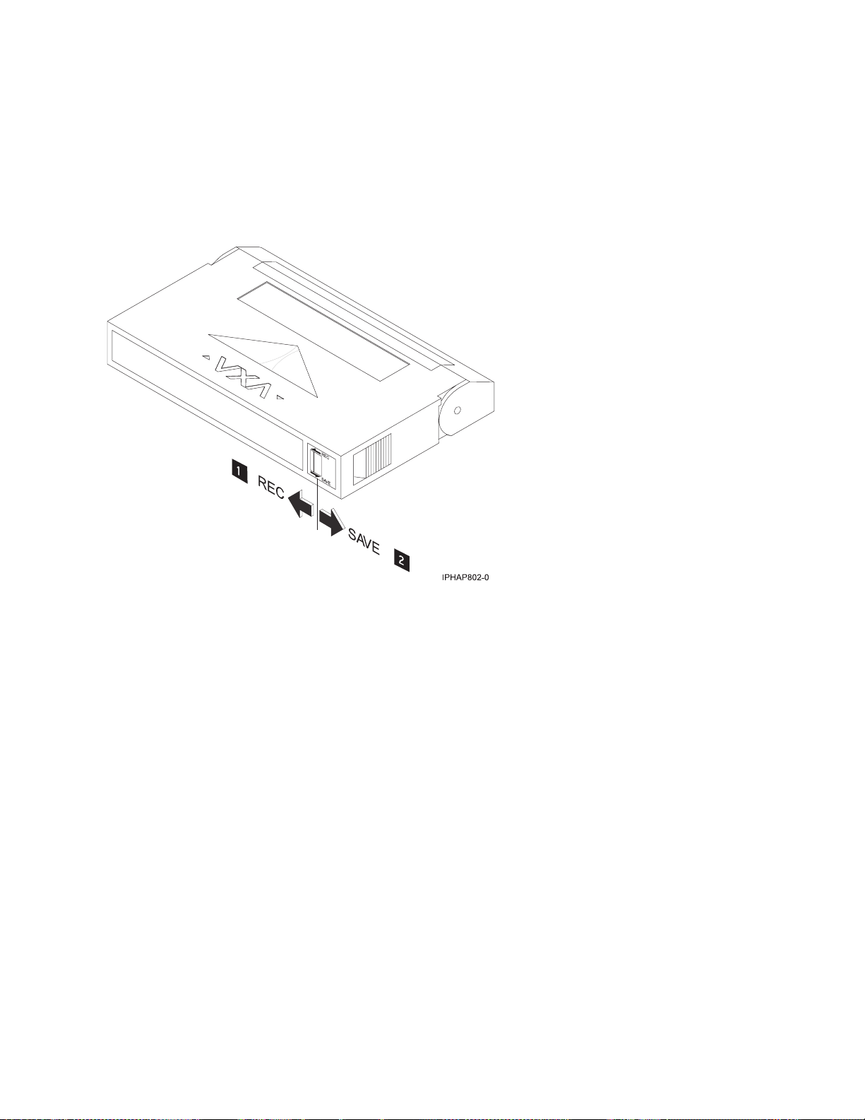
Setting the write-protect switch (FC 6120)
You might need to set the write-protect switch on your tape drive. Use the information in this topic to
perform this task.
Attention: Do not attempt to change the write-protect settings after the tape cartridge is loaded in the
drive because this might cause unpredictable results and might damage the tape or the drive.
The position of the write-protect switch on the tape cartridge determines when you can write to the tape.
1 When the switch is set to the left, data can be written to and read from the tape.
2 When the switch is set to the right, data can only be read.
Status lights (FC 6120)
You might need to read the status lights on your tape drive to determine the operating status of the
drive. Use the information in this topic to perform this task.
The following illustration is a front view of the tape drive:
38 Power Systems: Managing devices
Page 51

Figure 4. Front view of tape drive
1 Ready (green)
2 Active (green)
3 Cleaning (amber)
4 Fault (amber)
5 Eject button
The status lights and their ISO symbols are on the device as follows:
Ready
Activity
Cleaning
Fault
(green)
(green)
(amber)
(amber)
The combinations of the lights and their definitions are shown in the following table.
Table 19. Definition of status light combinations
Ready
Activity
Cleaning
Operation
Power-on self-test
1
Flashing Off Off Off
Power On LED Test On for 2.0 seconds On for 2.0 seconds On for 2.0 seconds On for 2.0 seconds
2
No tape loaded Off Off On
Cartridge loaded, no
activity
On Off On
Data or Cleaning
Cartridge loaded,
On Flashing On
/Off Off
2
/Off Off
2
/Off Off
activity
Fault
Chapter 2. Managing tape drives 39
Page 52

Table 19. Definition of status light combinations (continued)
Ready
Operation
Activity
Cleaning
Fault
Cleaning Cartridge
loaded, cleaning
2
failed
Cartridge loading or
unloading
Unrecoverable drive
failure
Firmware Download Flashing Off On2/Off Off
Firmware Update Flashing Flashing On
Microcode Download
failure
Over Temperature
2
3
4
5
Off Off On
Off Flashing On2/Off Off
On/Off Off On2/Off Flashing
Off Off On2/Off Flashing
Off Off On2/Off On
2
2
/Off Off
Off
3
3
Notes:
1. If the drive completes the power-on self-test (POST) within the 2.0 second Power On LED Test time,
the POST indicator sequence is eliminated
2. A solid amber LED indicates the drive needs cleaning. The drive will continue to function, but needs
cleaning as soon as possible. A power cycle does not turn off this indicator.
3. The Fault LED will flash to indicate an unrecoverable error. An unrecoverable error is an error
condition that results in the drive not being able to function unless initiator, operator, or service
intervention is applied. An unrecoverable drive failure is usually the result of a hardware error
condition. One of the following actions will be needed to clear the flashing Fault LED:
v Hard SCSI reset
v Cartridge eject
v Power cycle
v Retry microcode download
An unrecoverable cartridge (media) failure is usually the result of a defective cartridge, media, or
cartridge state and will require the drive to eject the cartridge (if possible) to clear the flashing LED.
4. The firmware download failed and the drive is not functional. The drive boot code is in control and
the microcode download should be retried. The drive can be identified using the Inquiry command
and is bootable while in this state.
5. The Fault LED will be on solid to indicate an over-temperature condition.
Performing the internal self-test (FC 6120 or 6279)
Use the information in this topic to perform an internal self-test on your tape drive.
Prerequisites
In order to perform the test, you need the following items:
v One VXA-2 tape drive with firmware code V2123 or higher, or one VXA-320 tape drive with firmware
V3209 or higher
v One VXA cleaning cartridge X style
v One blank VXA X23 data cartridge
40 Power Systems: Managing devices
Page 53

Performing the test
Follow these steps to perform the internal self-test:
Attention: Use a blank tape to perform the test. During the test, the tape is overwritten with a test
pattern and all data on the tape is destroyed.
1. Clean the tape drive.
2. Press the blue eject button for 7 seconds. When the Ready LED blinks rapidly, insert the blank, X23
data cartridge.
The tape drive performs the internal self-test. The test can take up to 15 minutes. After successful
completion, the media is ejected.
Interpreting the results
The following table shows how to interpret the results of the internal self-test using the status lights. To
see a front-view illustration of the tape drive and status lights, see one of the following illustrations.
VXA-320 tape drive: Figure 3 on page 31
VXA-2 tape drive: Figure 4 on page 39
If the internal self-test passes, then the tape drive has no hardware fault and no further tests are required.
If the internal self-test indicates a drive failure, contact your service provider.
Table 20. Internal self-test status light combinations
Internal self-test
operation
Ready
Activity
Cleaning
Fault
Media status
Initiated Flashing rapidly Off Off Off Unloaded
Running Flashing rapidly Flashing Off Off Loaded
Passed Off Off Off Off Unloaded
Passed, cleaning
needed
Media failure
Media
write-protected
Internal self-test
media not
compatible
Drive failure Off Off Off Flashing Loaded
1
Repeat the internal self-test with a different, blank X23 data cartridge.
2
Repeat the internal self-test with a write-enabled, blank X23 data cartridge.
1
2
1
Off Off On Off Unloaded
Off Off Flashing Off Loaded
Off Flashing Flashing Off Unloaded
Off Flashing Flashing Off Unloaded
Tape cartridges (FC 6120)
Learn about the types of tape cartridges that are available for this drive.
Compatible tape cartridges
Two types of tape cartridges are supported by this tape drive:
v X cartridges are the newest version of the VXA cartridge
v V cartridges are the original VXA cartridge
Chapter 2. Managing tape drives 41
Page 54

The V and X cartridges have similar shells and come in a variety of tape lengths. Both cartridges utilize
AME media and offer the similar read/write speeds and capacities.
Note:
1. To use X cartridges, the tape drive must have a minimum microcode level of 2105. To display the
microcode level of the tape drive in the AIX operating system, do the following steps:
a. Open an AIX command prompt.
b. Type the lscfg -vl rmtx command, where x is the tape drive number, then press Enter.
The output will contain the following line:
Device Specific.(Z1)........2105
In the previous example, 2105 represents the microcode level. If the command output contains a value
of 2105 or higher, the tape drive supports the use of X cartridges. If the command output contains a
value of 2104 or lower, update your microcode to 2105 or higher to use X cartridges in this tape drive.
2. X cartridges are only supported in VXA-2 tape drives. A user can write an X cartridge in VXA-1
format on a VXA-2 tape drive, but it will only be readable on a VXA-2 drive.
3. The VXA-2 drive supports use of V10 media, but this cartridge is not offered.
Available tape cartridges
Table 21. X tape cartridges
Part Number Description Type Other information
24R2137 230m 80/160GB X23 Data Cartridge Green accent
24R2136 124 m 40/80GB X17 Data Cartridge Green accent
24R2134 20/40GB X6 Data Cartridge Green accent
24R2135 62m 20/40GB X6 Test Cartridge Green accent
24R2138 X Cleaning Cartridge VXA 20 usage Green accent
Table 22. V tape cartridges
Part Number Description Type Other information
19P4876 230m 80/160GB V23 Data Cartridge Purple accent
19P4877 124 m 40/80GB V17 Data Cartridge Red accent
19P4878 20/40GB V6 Data Cartridge Blue accent
19P4879 62m 20/40GB V6 Test Cartridge Blue accent
19P4880 X Cleaning Cartridge VXA 20 usage Gray accent
Resetting the tape drive
You might need to reset your tape drive. Use the procedure in this topic to perform this task.
Use this information to reset your tape drive, without affecting server operation. Allow up to 2 minutes
for the entire tape drive process to complete.
Attention: Resetting a tape drive before the current backup operation has completed can cause loss of
customer data.
To reset the tape drive, follow these steps:
1. Press and hold the eject button for 20 seconds, and then release the button. The LEDs on the drive
will be flashing while the reset function is in process.
42 Power Systems: Managing devices
Page 55

2. When the LEDs stop flashing, wait approximately one minute for the drive to complete the reset
operation. The drive will then be ready to use.
60/150 GB 16-bit 8-mm internal tape drive (FC 6134)
Learn about the features of this media device.
Description The 60/150GB 16-bit 8-mm Internal Tape Drive consists of a 5.25-inch half-high, 16-bit tape
drive. This drive provides a high capacity tape drive for save/restore and archiving
functions. This tape drive uses IBM 8-mm data cartridges and is capable of compression,
providing a capacity of up to 150 GB. The 60/150 GB 16-bit 8-mm Internal Tape Drive, is
limited to a maximum system ambient operating temperature of 31C (87.8F) at a maximum
operating altitude of 2134m (7000 ft). Lower altitudes have higher maximum ambient
operating temperatures.
Characteristics:
v FRU part number: 19P0708
v Custom card identification number (CCIN): 63A0
v Capacity: 60 GB Native Mode, 150 GB (typical) Compression Mode
v Form Factor: 5.25-inch Half-high
v Media: IBM 8-mm Data Cartridge with SmartClean Technology
v Operation: Streaming
v Data Transfer Rate: 12 MB/Sec. Native Mode, 30 MB/Sec. (typical) Compression M
v Interface: SCSI-2 16-bit Low Voltage Differential (LVD) / Single-ended (SE)
Asynchronous/Synchronous
v Compatibility: Contact your authorized service provider
v Attributes provided: 60/150GB 16-bit 8-mm Internal Tape Drive
v Attributes required: One 1.6-inch (41mm) half-high media bay and one SCSI-2 internal
16-bit address
Tools The following tools and documentation are needed to complete the installation:
v A flat-blade screwdriver (if this device is not an auto-docking feature on your system)
v Your system unit documentation, including any service documentation
v Your operating system documentation
If an item is missing or damaged, contact the place of purchase.
Note: If you are installing the auto-docking version of this device on your system, the
remainder of this information does not apply to your system. See your system
documentation for information about the auto-docking feature.
Related information Check that your package contains the following items:
v The device
v Media kit containing:
– 1 data cartridge
– 1 cleaning cartridge
– 1 test tape
– Jumpers (located in a plastic bag)
v Specific hardware for attaching the device to your specific system, as detailed on the parts
listing provided with your device
Cleaning the tape drive (FC 6134)
You will need to clean your tape drive. Use the procedure in this topic to perform this task.
Chapter 2. Managing tape drives 43
Page 56

Clean the device whenever the Fault status light comes on or a system I/O error related to the device
occurs.
Attention: Use only the recommended cleaning cartridge to clean the tape drive. Use of other than
recommended cleaning cartridges can damage your drive and might void the warranty.
The tape drive will turn on the cleaning indication for several reasons:
v The tape drive exceeds internal preset error thresholds in the drive.
v A cleaning cartridge that has been used the maximum number of times is inserted in the drive. The
cleaning indicator is turned on to indicate that the cleaning process was not done and the cleaning
cartridge is no longer usable.
v The tape drive exceeds the maximum recommended time between cleaning.
If SmartClean data cartridges are not used, clean the tape drive with a cleaning cartridge when the tape
drive amber LED (Disturbance LED) indicates the drive needs cleaning due to time of tape movement or
recording quality problems. The LCD will say ″CLEAN SOON″. The maximum time between cleaning
will be 30 tape motion hours.
Note: The 6134 tape drive is optimized to use SmartClean media. Extended use of AME media that is
not SmartClean media is not recommended.
To clean the tape drive, complete the following steps:
1. Make sure that the power is on to the tape drive.
2. If a tape cartridge is in the tape drive, eject and remove the cartridge.
Note: Some cleaning cartridges have white dots on the window side that are designed to be used to
log the use of the cartridge. Each time the cartridge is used, mark one of the dots on the cartridge
with a pen or marker. When all of the dots have been marked, discard the cleaning cartridge.
3. Grasp the cleaning cartridge by the outer edges, with the window-side up and the write-protect
switch facing you.
4. Slide the cartridge into the opening on the front of the drive until the loading mechanism pulls the
cartridge into the drive and the drive door closes.
After the cleaning cartridge has been inserted, the remainder of the cleaning process is automatic. The
tape drive does the following actions:
v Loads the cleaning cartridge into the tape drive.
v Cleans the drive by moving the cleaning tape forward for approximately 30 seconds.
v Unloads the cleaning cartridge when the cleaning operation is complete.
v Indicates a successful cleaning operation by turning off the Fault status light (if the Fault light was on
prior to the cleaning process.
Note: If the cleaning operation completes but the Fault light remains on, repeat the cleaning procedure
with a new cleaning cartridge. If the light still remains on, contact your authorized service provider.
To determine how many times a cleaning cartridge can be used, check the information printed on the
cartridge. If you attempt to use a depleted cleaning cartridge, the tape drive automatically detects the
error and ejects the cartridge. If the Fault status light was on prior to the cleaning process, it stays on; if
the Fault light was off, the depleted cartridge causes the light to come on.
If a system error occurs, clean the drive and retry the operation. If the operation fails, replace the data
cartridge, clean the drive again, then retry the operation.
44 Power Systems: Managing devices
Page 57

Loading and unloading cartridges
Learn about loading and unloading tape cartridges from this drive.
To avoid problems with loading and unloading, use only one label on a cartridge. If the cartridge has too
many or poorly-placed labels, the drive-load mechanism might clog.
Loading a cartridge
To load a cartridge, complete the following steps:
1. Make sure that the tape device power is on.
2. Grasp the cartridge by the outer edges, with the window side up and the write-protect switch facing
you.
Note: Make sure that the write-protect switch is correctly set.
3. Slide the cartridge into the opening on the front of the device until the loading mechanism pulls the
cartridge into the drive and the drive door closes.
To indicate that the load operation was successful, the Ready status light comes on.
Unloading a cartridge
To unload a cartridge, complete the following steps:
1. Make sure that the tape device power is on.
2. Press the Unload button. The device rewinds, unloads, and ejects the tape cartridge.
The process might take from 15 seconds to several minutes, depending on the position of the tape and
the amount of data written. During this task, the status lights do the following sequence:
v The Ready status light turns off.
v The Activity status light flashes during the unload operation.
v The Activity status light turns off when the cartridge is ejected from the tape drive.
Attention: An emergency eject and reset feature can be used to release the tape cartridge and reset the
drive. Use the emergency eject feature if the cartridge does not move correctly or if the unload process
fails. The emergency eject and reset feature procedure might result in loss of data. To perform an
emergency eject operation of the tape cartridge or a reset operation of the drive, press and hold the
Unload button for at least 10 seconds. If a cartridge is in the drive, the cartridge automatically ejects
without rewinding the tape.
Setting the write-protect switch (FC 6134)
You might need to set the write-protect switch on your tape drive. Use the information in this topic to
perform this task.
The position of the write-protect switch on the tape cartridge determines when you can write to the tape.
Chapter 2. Managing tape drives 45
Page 58

When the switch is set to the left in the SAVE position 1, data cannot be written to or read from the tape (data is
saved).
When the switch is set to the right in the REC (Record) position 2, data can be written to and read from the tape.
Status lights (FC 6134)
You might need to read the status lights on your tape drive to determine the operating status of the
drive. Use the information in this topic to perform this task.
The following illustration is a front view of the tape drive:
46 Power Systems: Managing devices
Page 59

Figure 5. Front view of tape drive
1 Unload button
2 Status lights
3 Liquid crystal display (LCD)
The status lights and their ISO symbols are on the device as follows:
Ready
Activity
Fault
(green)
(green)
(amber)
The combinations of the lights and their definitions are shown in the following table.
Table 23. Definition of status light combinations
Ready
Operation
POST or Reset On On On
Error or Failed POST Off Off Flash
Ready (No Cartridge
Loaded)
Ready (Cartridge Loaded) On Off
Normal Cartridge Motion On Flashing
High Speed Motion On Fast Flashing
Time to Clean Cartridge N/A N/A On
Cleaning in Progress On Flashing On
Off Off
Activity
Fault
Tape cartridges (FC 6134)
Learn about the types of tape cartridges that are available for this drive.
Chapter 2. Managing tape drives 47
Page 60

Available tape cartridges
Table 24. 8-mm data cartridges
Part Number Type of Cartridge Length
35L1044 20 GB AME with SmartClean Data Cartridge 75 m (246 ft)
09L5323 40 GB AME with SmartClean Data Cartridge 150 m (492 ft)
18P6484 60 GB AME with SmartClean Data Cartridge 225 m (738 ft)
35L1409 Cleaning Cartridge
Resetting the tape drive
You might need to reset your tape drive. Use the procedure in this topic to perform this task.
Use this information to reset your tape drive, without affecting server operation. Allow up to 2 minutes
for the entire tape drive process to complete.
Attention: Resetting a tape drive before the current backup operation has completed can cause loss of
customer data.
To reset the tape drive, follow these steps:
1. Press and hold the eject button for 20 seconds, and then release the button. The LEDs on the drive
will be flashing while the reset function is in process.
2. When the LEDs stop flashing, wait approximately one minute for the drive to complete the reset
operation. The drive will then be ready to use.
36/72 GB Data72 4 mm internal tape drive (FC 6258 or 5907)
Learn about the features of this media device.
Description The 36/72 GB Data72 4 mm Internal Tape Drive is a 5.25-inch, half-high, LVD or SAS drive,
which provides a high capacity for save/restore and achieve functions. This tape drive uses
IBM 4 mm data cartridges and is capable of compression, providing a capacity of up to 72
GB.
Characteristics:
v FRU part number for FC 6258: 95P1988
v FRU part number for FC 5907: 23R2530
v Custom card identification number (CCIN): 63A0
v Capacity: 36 GB native mode, 72 GB (typical) compression mode
v Form Factor: 5.25-inch half high
v Media: DAT72, DDS4, and DDS3 media
v Technology: Helical scan, rotating head
v Operation: Streaming
v Data Transfer Rate: 3 MBps native mode, 6 MBps (typical) compression
v Interface for FC 6258: Low voltage differential
v Interface for FC 5907: Serial-Attached SCSI
v Compatibility: 12 GB mode (read/write), 20 GB (read/write), and 36 GB mode
(read/write)
v Attributes provided: 4 mm tape capability
v Attributes required: One 1.6-inch (41 mm) half-high media bay and one SCSI internal LVD
or SAS 16-bit address
48 Power Systems: Managing devices
Page 61

Tools The following tools and documentation are needed to complete the installation:
v A flat-blade screwdriver (if this device is not an auto-docking feature on your system)
v Your system unit documentation, including any service documentation
v Your operating system documentation
Contact the place of purchase if an item is missing or damaged.
Note: If you are installing the auto-docking version of this device on your system, the
remainder of this section does not apply to your system. See your system documentation for
information about the auto-docking feature.
Media This tape drive uses 4mm data cartridges for saving and restoring system data. It is designed
to use only DDS (Digital Data Storage) data cartridges. The cartridges are identified by one
of the following DDS symbols:
Digital
Data
Storage
3
The tape drive reads and writes data to tape cartridges that are DDS-3, DDS-4, or DAT 72
format.
Note: This tape drive only supports DDS-3, DDS-4, and DAT 72 tape cartridges. If any other
cartridge is inserted in the drive, it will be ejected.
This tape drive has been designed to operate with DDS media that meet the following
standards of the European Computer Manufacturers Association (ECMA):
v ECMA-236 DDS-3 format
v ECMA-288 DDS-4 format
Related information Your package contains the following items:
v The tape drive
v Media kit containing:
– 1 cleaning cartridge
– 1 test tape
– Jumpers (located in a plastic bag)
v Specific hardware for attaching the drive to your specific system, as detailed on the parts
listing provided with your drive.
Or Or
4
Digital
Data
Storage
DAT
Digital Data Storage
72
Cleaning the tape drive (FC 6258 or 5907)
You will need to clean your tape drive. Use the procedure in this topic to perform this task.
Clean the device whenever the Fault status light comes on or a system I/O error related to the device
occurs.
Attention: Use only the recommended cleaning cartridge to clean the tape drive. Use of other than
recommended cleaning cartridges can damage your drive and might void the warranty.
The tape drive will turn on the cleaning indicator for the following reasons:
v The tape drive exceeds internal preset error thresholds in the drive.
v A cleaning cartridge that has been used the maximum number of times is inserted in the drive. The
cleaning indicator is turned on to indicate that the cleaning process was not done and the cleaning
cartridge is no longer usable.
v The tape drive exceeds the maximum recommended time between cleaning.
The maximum recommended time between preventive-maintenance cleaning is 50 tape motion hours.
Tape motion hours are defined as the time that the tape drive is moving tape. If the tape drive reaches 50
tape motion hours since the tape drives was last cleaned, the drive will turn on the cleaning required
Chapter 2. Managing tape drives 49
Page 62

LED to indicate the drive needs cleaning. The tape drive will continue to operate but the tape drive
should be cleaned at the next opportunity to insert a cleaning cartridge.
To clean the tape drive, complete the following steps:
1. Make sure that the power is on to the tape drive.
2. If a tape cartridge is in the tape drive, eject and remove the cartridge.
Note: Some cleaning cartridges have white dots on the window side that are designed to be used to
log the use of the cartridge. Each time the cartridge is used, mark one of the dots on the cartridge
with a pen or marker. When all of the dots have been marked, discard the cleaning cartridge.
3. Grasp the cleaning cartridge by the outer edges, with the window-side up and the write-protect
switch facing you.
4. Slide the cartridge into the opening on the front of the drive until the loading mechanism pulls the
cartridge into the drive and the drive door closes.
After the cleaning cartridge has been inserted, the remainder of the cleaning process is automatic. The
tape drive does the following actions:
v Loads the cleaning cartridge into the tape drive.
v Cleans the drive by moving the cleaning tape forward for approximately 30 seconds.
v Unloads the cleaning cartridge when the cleaning operation is complete.
v Indicates a successful cleaning operation by turning off the Fault status light (if the Fault light was on
prior to the cleaning process.
Note: If the cleaning operation completes but the Fault light remains on, repeat the cleaning procedure
with a new cleaning cartridge. If the light still remains on, contact your authorized service provider.
To determine how many times a cleaning cartridge can be used, check the information printed on the
cartridge. If you attempt to use a depleted cleaning cartridge, the tape drive automatically detects the
error and ejects the cartridge. If the Fault status light was on prior to the cleaning process, it stays on; if
the Fault light was off, the depleted cartridge causes the light to come on.
If a system error occurs, clean the drive and retry the operation. If the operation fails, replace the data
cartridge, clean the drive again, then retry the operation.
Loading and unloading cartridges
Learn about loading and unloading tape cartridges from this drive.
To avoid problems with loading and unloading, use only one label on a cartridge. If the cartridge has too
many or poorly-placed labels, the drive-load mechanism might clog.
Loading a cartridge
To load a cartridge, complete the following steps:
1. Make sure that the tape device power is on.
2. Grasp the cartridge by the outer edges, with the window side up and the write-protect switch facing
you.
Note: Make sure that the write-protect switch is correctly set.
3. Slide the cartridge into the opening on the front of the device until the loading mechanism pulls the
cartridge into the drive and the drive door closes.
To indicate that the load operation was successful, the Ready status light comes on.
50 Power Systems: Managing devices
Page 63
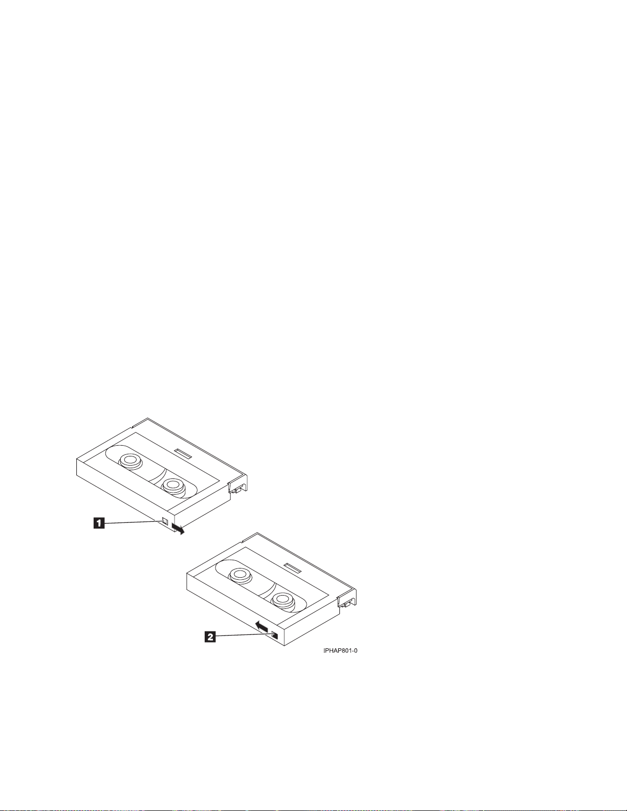
Unloading a cartridge
To unload a cartridge, complete the following steps:
1. Make sure that the tape device power is on.
2. Press the Unload button. The device rewinds, unloads, and ejects the tape cartridge.
The process might take from 15 seconds to several minutes, depending on the position of the tape and
the amount of data written. During this task, the status lights do the following sequence:
v The Ready status light turns off.
v The Activity status light flashes during the unload operation.
v The Activity status light turns off when the cartridge is ejected from the tape drive.
Attention: An emergency eject and reset feature can be used to release the tape cartridge and reset the
drive. Use the emergency eject feature if the cartridge does not move correctly or if the unload process
fails. The emergency eject and reset feature procedure might result in loss of data. To perform an
emergency eject operation of the tape cartridge or a reset operation of the drive, press and hold the
Unload button for at least 10 seconds. If a cartridge is in the drive, the cartridge automatically ejects
without rewinding the tape.
Setting the write-protect switch (FC 6258 or 5907)
You might need to set the write-protect switch on your tape drive. Use the information in this topic to
perform this task.
Attention: Do not attempt to change the write-protect settings after the tape cartridge is loaded in the
drive because this might cause unpredictable results and might damage the tape or the drive.
The position of the write-protect switch on the tape cartridge determines when you can write to the tape.
1 When the switch is set to the right, data can be written to and read from the tape
2 When the switch is set to the left, data can only be read.
Chapter 2. Managing tape drives 51
Page 64

Status lights (FC 6258 or 5907)
You might need to read the status lights on your tape drive to determine the operating status of the
drive. Use the information in this topic to perform this task.
The following illustration is a front view of the tape drive:
1
3
4
2
5
Figure 6. Front view of tape drive
1 Tape drive door
2 Status lights
3 Ready (green)
4 Active (green)
5 Fault (amber)
6 Unload/Reset button
6
The status lights and their ISO symbols are on the device as follows:
Ready
Ready (green)
Activity
Activity (green)
Fault
Fault (amber)
The combinations of the lights and their definitions are shown in the following table.
Table 25. Definition of status light combinations
Ready
Ready (green)
Flashing Off Off
Activity
Activity (green)
Fault
Fault (amber)
Definition
The power-on self-test (POST) is running or
the test cartridge is running.
52 Power Systems: Managing devices
Page 65

Table 25. Definition of status light combinations (continued)
Ready
Ready (green)
Off or On Off or Flashing On
Off Off Off or On
On Off or Flashing Off or On
On Flashing Off or On
Off Off Flashing
Activity
Activity (green)
Fault
Fault (amber)
Definition
The tape drive requires cleaning. See
Cleaning the tape drive.
v If the Ready light is on, a tape cartridge is
in the drive. If the light is off, a cartridge is
not in the drive.
v If the Activity light flashes, a tape cartridge
is in the drive and tape movement is
occurring. If the light is off, no tape
movement is occurring.
One of the following conditions exists:
v The power is off (Fault light is off).
v The POST completed successfully, but no
tape cartridge has been inserted.
v If the Fault light is on, cleaning is required.
See Cleaning the tape drive.
A data cartridge has been inserted.
v The device is ready to receive commands
from the system (whether the Fault light is
on or off).
v If the Fault light is on, cleaning is required.
See Cleaning the tape drive.
v If the Activity light flashes, a tape cartridge
is in the drive and tape movement is
occurring. If the light is off, no tape
movement is occurring.
The tape is in motion, and the device is
running an operation or is cleaning.
The device detected an internal fault that
requires corrective action.
1. Reset the error by turning the power off
to the device, then turning it back on, or
by holding down the Unload/Reset
button for 8 seconds.
2. If the Fault light still flashes after the
reset, contact your service provider.
Notes:
v The device needs cleaning when the tape drive turns on the Fault status light (solid amber). The light
turns on when the device exceeds a preset operating limit.
v The recommended preventive-maintenance cleaning frequency is approximately 50 tape motion hours.
Tape motion hours are defined as the time that the tape drive is moving tape.
v When the Fault light turns on (solid amber), the device causes AIX to log an information error
(TAPE_ERR6) in the AIX log, indicating that the tape drive needs to be cleaned.
v Use only quality media and cleaning cartridges.
v The device is designed to operate in typical office environments. Dirty environments or other poor
environments might damage the tape drive. It is the customer’s responsibility to provide the proper
operating environment.
Chapter 2. Managing tape drives 53
Page 66

v When the tape drive indicates that the drive needs to be cleaned, it is the customer’s responsibility to
clean the tape drive with the recommended cleaning cartridge.
v If a tape cartridge that is not DDS-3, DDS-4, or DAT72 format is used, that cartridge will be
immediately ejected as an incorrect cartridge type.
Tape cartridges (FC 6258 or 5907)
Learn about the types of tape cartridges that are available for this drive.
Available tape cartridges
Table 26. 4-mm Data Cartridges
IBM Part Number Type of Cartridge Native (uncompressed) Capacity
18P7912 DAT 72 Data Cartridge 36 GB
59H4456 4-mm Test Cartridge --
21F8763 4-mm Cleaning Cartridge --
59H3465 Data Cartridge DDS3 12 GB
59H4458 Data Cartridge DDS4 20 GB
Most bulk eraser devices do not have the capability to erase the 4mm data cartridge. To correctly erase a
4mm data cartridge with a bulk eraser device, the erasure coercivity rating must be a minimum of 3900
Oersted.
Resetting the tape drive
You might need to reset your tape drive. Use the procedure in this topic to perform this task.
Use this information to reset your tape drive, without affecting server operation. Allow up to 2 minutes
for the entire tape drive process to complete.
Attention: Resetting a tape drive before the current backup operation has completed can cause loss of
customer data.
To reset the tape drive, follow these steps:
1. Press and hold the eject button for 20 seconds, and then release the button. The LEDs on the drive
will be flashing while the reset function is in process.
2. When the LEDs stop flashing, wait approximately one minute for the drive to complete the reset
operation. The drive will then be ready to use.
80/160 GB DAT160 SAS Tape Drive (FC 5619)
Learn about the features of this media device.
54 Power Systems: Managing devices
Page 67

Description The 80/160 GB DAT160 SAS Tape Drive is a 5.25-inch, half-high, SAS drive, which provides
a high capacity for save/restore and achieve functions. To see an illustration of this drive, see
Figure 7 on page 58. This tape drive uses IBM DAT160, 4 mm data cartridges and is
compression capable, providing a capacity of up to 160 GB with 2:1 compression ratio.
Characteristics:
v FRU part number: 23R9723
v Custom card identification number (CCIN): 63A0
v Media part numbers: see “Tape cartridges (FC 5619)” on page 60
v Capacity: 80 GB native mode, 160 GB (typical) compression mode
v Form factor: 5.25-inch half high
v Media: DAT160, DAT72, and DDS4 media
v Technology: helical scan, rotating head
v Operation: streaming
v Data transfer rate: 6 MBps native mode, 12 MBps (typical) compression
v Interface: integrated, internal SAS
v Compatibility: DDS4 (read/write), DAT72 (read/write), and DAT160 (read/write)
v Attributes provided: 4 mm tape capability, test cartridge, cleaning cartridge, and a data
cartridge
v Attributes required: One 1.6-inch (41 mm) half-high media bay and one integrated, internal
SAS
Tools The following tools and documentation are needed to complete the installation:
v A flat-blade screwdriver (if this device is not an auto-docking feature on your system)
v Your system unit documentation, including any service documentation
v Your operating system documentation
Contact the place of purchase if an item is missing or damaged.
Note: If you are installing the auto-docking version of this device on your system, see your
system documentation for information about the auto-docking feature.
Media This tape drive uses 4 mm data cartridges for saving and restoring system data. It is
designed to use only DDS (Digital Data Storage) data cartridges. The cartridges are identified
by one of the following DDS symbols:
The tape drive reads and writes data to tape cartridges that are in the DDS4, DAT72, or
DAT160 format.
Related information Your package contains the following items:
v The tape drive
v Media kit containing:
– One cleaning cartridge
– One test tape
v Specific hardware for attaching the drive to your specific system, as detailed on the parts
listing provided with your drive.
Cleaning the tape drive (FC 5619)
You will need to clean your tape drive. Use the procedure in this topic to perform this task.
Chapter 2. Managing tape drives 55
Page 68

Clean the device whenever the Fault status light comes on or a system I/O error related to the device
occurs.
Attention: Use only the recommended cleaning cartridge to clean the tape drive. Use of other than
recommended cleaning cartridges can damage your drive and might void the warranty. The cleaning
cartridge for this drive is P/N 23R5638. The cartridge is physically larger than previous cleaning
cartridges and it is the only cleaning cartridge that can be used in this drive. The older, narrower
cleaning cartridges do not work in the 5619 tape drive and are ejected from the drive without cleaning
the drive.
The tape drive will turn on the cleaning indicator for the following reasons:
v The tape drive exceeds internal preset error thresholds in the drive.
v A cleaning cartridge that has been used the maximum number of times is inserted in the drive. The
cleaning indicator is turned on to indicate that the cleaning process was not done and the cleaning
cartridge is no longer usable.
v The tape drive exceeds the maximum recommended time between cleaning.
The maximum recommended time between preventive-maintenance cleaning is 50 tape motion hours.
Tape motion hours are defined as the time that the tape drive is moving tape. If the tape drive reaches 50
tape motion hours since the tape drives was last cleaned, the drive will turn on the cleaning required
LED to indicate the drive needs cleaning. The tape drive will continue to operate but the tape drive
should be cleaned at the next opportunity to insert a cleaning cartridge.
Note: Operating the tape drive in a low-humidity environment causes the drive to request cleaning more
often than in normal humidity environment. In extreme low-humidity conditions of less than 15% relative
humidity, the tape drive might request cleaning every 10 tape motion hours or even more frequently. For
this reason, it is best not to use the tape drive in extremely low-humidity environments.
To clean the tape drive, complete the following steps:
1. Make sure that the power is on for the tape drive.
2. If a tape cartridge is in the tape drive, eject and remove the cartridge.
3. Grasp the cleaning cartridge by the outer edges, with the window-side up and the write-protect
switch facing you.
4. Slide the cartridge into the opening on the front of the drive until the loading mechanism pulls the
cartridge into the drive and the drive door closes.
After the cleaning cartridge has been inserted, the remainder of the cleaning process is automatic. The
tape drive does the following actions:
v Loads the cleaning cartridge into the tape drive.
v Cleans the drive by moving the cleaning tape forward for approximately 30 seconds.
v Unloads the cleaning cartridge when the cleaning operation is complete.
v Indicates a successful cleaning operation by turning off the Cleaning status light (if the Cleaning light
was on prior to the cleaning process. Otherwise, the Cleaning light remains solid to indicate that the
cleaning cartridge is no longer usable. Obtain a new cleaning cartridge and repeat the process.)
Note: If the cleaning operation completes but the Cleaning light remains on, repeat the cleaning
procedure with a new cleaning cartridge. If the light still remain on, contact your authorized service
representative.
If you attempt to use a depleted cleaning cartridge, the drive automatically detects the error and ejects
the cartridge. If the Cleaning status light was on prior to the cleaning process, it stays on; if the Cleaning
light was off, the depleted cartridge causes the light to come on.
56 Power Systems: Managing devices
Page 69

If a system error occurs, clean the drive and retry the operation. If the operation fails, replace the data
cartridge, clean the drive again, then retry the operation.
Loading and unloading cartridges
Learn about loading and unloading tape cartridges from this drive.
To avoid problems with loading and unloading, use only one label on a cartridge. If the cartridge has too
many or poorly-placed labels, the drive-load mechanism might clog.
Loading a cartridge
To load a cartridge, complete the following steps:
1. Make sure that the tape device power is on.
2. Grasp the cartridge by the outer edges, with the window side up and the write-protect switch facing
you.
Note: Make sure that the write-protect switch is correctly set.
3. Slide the cartridge into the opening on the front of the device until the loading mechanism pulls the
cartridge into the drive and the drive door closes.
To indicate that the load operation was successful, the Ready status light comes on.
Unloading a cartridge
To unload a cartridge, complete the following steps:
1. Make sure that the tape device power is on.
2. Press the Unload button. The device rewinds, unloads, and ejects the tape cartridge.
The process might take from 15 seconds to several minutes, depending on the position of the tape and
the amount of data written. During this task, the status lights do the following sequence:
v The Ready status light turns off.
v The Activity status light flashes during the unload operation.
v The Activity status light turns off when the cartridge is ejected from the tape drive.
Attention: An emergency eject and reset feature can be used to release the tape cartridge and reset the
drive. Use the emergency eject feature if the cartridge does not move correctly or if the unload process
fails. The emergency eject and reset feature procedure might result in loss of data. To perform an
emergency eject operation of the tape cartridge or a reset operation of the drive, press and hold the
Unload button for at least 10 seconds. If a cartridge is in the drive, the cartridge automatically ejects
without rewinding the tape.
Setting the write-protect switch (FC 5619)
You might need to set the write-protect switch on your tape drive. Use the information in this topic to
perform this task.
Attention: Do not attempt to change the write-protect settings after the tape cartridge is loaded in the
drive because this might cause unpredictable results and might damage the tape or the drive.
The position of the write-protect switch on the tape cartridge determines when you can write to the tape.
Chapter 2. Managing tape drives 57
Page 70
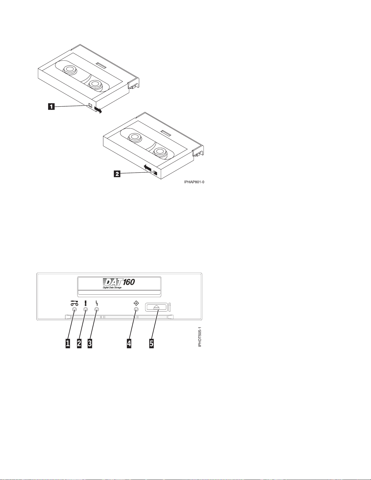
1 When the switch is set to the right, data can be written to and read from the tape.
2 When the switch is set to the left, data can only be read.
Status lights (FC 5619)
You might need to read the status lights on your tape drive to determine the operating status of the
drive. Use the information in this topic to perform this task.
The following illustration is a front view of the tape drive:
Figure 7. Front-view of tape drive
1 Cleaning LED (amber)
2 Media fault LED (amber)
3 Drive fault LED (amber)
4 Ready/Activity LED (green)
5 Unload/Reset button
The combinations of the lights and their definitions are shown in the following table.
58 Power Systems: Managing devices
Page 71

Table 27. Definition of status light combinations
Cleaning (amber)
Activity
Media fault (amber)
Drive fault (amber)
Ready/Activity
(green)
Power on LED test (2.0
seconds)
Power on self-test
(POST) activity
On On On On
Off Off Off Flashing
POST failed Off Off Flashing Off
1
POST passed On
Data cartridge loading On
Data cartridge loaded,
no activity
Data cartridge loaded,
activity
Data cartridge
unloading
Data cartridge ejected On
Cleaning cartridge
loaded, activity
Cleaning succeeded,
cleaning cartridge
or off Off Off Off
1
or off Off Off Flashing
1
or off On2or off Flashing3or off On
On
1
or off On2or off Flashing3or off Flashing
On
1
or off On2or off Flashing3or off Flashing
On
1
or off On or off Flashing3or off Off
3
On Off Flashing
Off Off Flashing
or off Flashing
3
or off Off
ejected
Cleaning failed,
cleaning cartridge
On
1
On Flashing3or off Off
ejected
Unrecoverable drive
4
failure
Unrecoverable media
4
failure
On1or off On or off Flashing Flashing
1
On
On Off Flashing, on, or off
Firmware download:
download and
Flashing Off Off Flashing
reprogram
Firmware download:
possible unload
Firmware download:
reset in 1 second
Firmware download:
self-test
Firmware download
reprogram failure
SCSI diagnostics test in
progress
SCSI diagnostics test
passed
SCSI diagnostics test
failed, tape ejected
See Data cartridge unloading
On On On On
See Power on self-test activity, and then see either POST passed or POST failed.
Off Off Flashing Off
See Data cartridge loaded, activity
See Data cartridge loaded, no activity
On On On Flashing
After data cartridge ejects, see Data cartridge ejected.
Chapter 2. Managing tape drives 59
Page 72

Table 27. Definition of status light combinations (continued)
Cleaning (amber)
Activity
Media fault (amber)
Drive fault (amber)
Ready/Activity
(green)
Tape diagnostics test in
progress
Tape diagnostics test
passed, tape ejected
Tape diagnostics test
failed, tape ejected
1
A solid amber Cleaning LED indicates that the drive needs cleaning. The drive will continue to function but needs
cleaning as soon as possible. Do not ignore the indicator by cycling the power to turn it off.
2
The media has reached the end of its useful life and should be replaced. Any data should be copied to a new
cartridge as soon as possible.
3
Flashing in this state indicates a problem with write/read performance.
4
An unrecoverable drive failure is an error condition that results in the drive not being able to function unless
initiator, operator, or service intervention is applied. An unrecoverable drive failure is usually the result of a
hardware error condition. One of the following actions is needed to clear the flashing fault LED:
v Hard SCSI reset
v Cartridge emergency eject
v Power cycle
v Retry firmware download
An unrecoverable media failure is usually the result of a defective cartridge, media, or cartridge state, and will
require the drive to eject the cartridge (if possible) to clear the On LED.
See Data cartridge loading and then:
Flashing Off Off Flashing
Off Off Off Flashing
After data cartridge ejects, see Data cartridge ejected.
On On On Flashing
After data cartridge ejects, see Data cartridge ejected.
Tape cartridges (FC 5619)
Learn about the types of tape cartridges that are available for this drive.
Available tape cartridges
Table 28. 4 mm data cartridges
IBM part number Type of cartridge
23R5635 (cartridge feature code 5689) DAT160 80 GB Data Cartridge
23R5636 4 mm Test Cartridge
23R5638 4 mm Cleaning Cartridge
Most bulk eraser devices do not have the capability to erase the 4 mm data cartridge.
Resetting the tape drive
You might need to reset your tape drive. Use the procedure in this topic to perform this task.
Use this information to reset your tape drive, without affecting server operation. Allow up to 2 minutes
for the entire tape drive process to complete.
Attention: Resetting a tape drive before the current backup operation has completed can cause loss of
customer data.
60 Power Systems: Managing devices
Page 73

To reset the tape drive, follow these steps:
1. Press and hold the eject button for 20 seconds, and then release the button. The LEDs on the drive
will be flashing while the reset function is in process.
2. When the LEDs stop flashing, wait approximately one minute for the drive to complete the reset
operation. The drive will then be ready to use.
160/320 GB DAT320 SAS Tape Drive (FC 5661)
Learn about the features of this media device.
Description The 160/320 GB DAT320 SAS Tape Drive is a 5.25-inch, half-high, SAS drive, which provides
a high capacity for save/restore and achieve functions. To see an illustration of this drive, see
Figure 8 on page 64. This tape drive uses IBM DAT320, 4 mm data cartridges and is
compression capable, providing a capacity of up to 320 GB with 2:1 compression ratio.
Characteristics:
v FRU part number: 46C1933
v Custom card identification number (CCIN): 63A0
v Media part numbers: see “Tape cartridges (FC 5661)” on page 67
v Capacity: 160 GB native mode, 320 GB (typical) compression mode
v Form factor: 5.25-inch half high
v Media: DAT320, DAT160
v Technology: helical scan, rotating head
v Operation: streaming
v Data transfer rate: 12 MBps native mode
v Interface: integrated, internal SAS with right-angle connector.
v Compatibility: DAT160 (read/write) and DAT320 (read/write)
Note: DAT160 media is more abrasive than DAT320 media and can be used for occasional
use only.
v Attributes provided: DAT320 tape, test cartridge, and a cleaning cartridge
v Attributes required: One 1.6-inch (41 mm) half-high media bay and Feature Code 3657,
SAS cable with right angle connector.
Tools The following tools and documentation are needed to complete the installation:
v A flat-blade screwdriver (if this device is not an auto-docking feature on your system)
v Your system unit documentation, including any service documentation
v Your operating system documentation
Contact the place of purchase if an item is missing or damaged.
Note: If you are installing the auto-docking version of this device on your system, see your
system documentation for information about the auto-docking feature.
Media This tape drive uses 4 mm data cartridges for saving and restoring system data. It is
designed to use only DDS (Digital Data Storage) data cartridges. The cartridges are identified
by one of the following DDS symbols:
The tape drive reads and writes data to tape cartridges that are in the DAT160 or DAT320
format.
Chapter 2. Managing tape drives 61
Page 74

Related information Your package contains the following items:
v The tape drive
v Media kit containing:
– One cleaning cartridge
– One test cartridge
v Specific hardware for attaching the drive to your specific system, as detailed on the parts
listing provided with your drive.
Cleaning the tape drive (FC 5661)
You will need to clean your tape drive. Use the procedure in this topic to perform this task.
Clean the device whenever the Fault status light comes on or a system I/O error related to the device
occurs.
Attention: Use only the recommended cleaning cartridge to clean the tape drive. Use of other than
recommended cleaning cartridge damages your drive and voids the warranty. The cleaning cartridge for
this drive is P/N 46C1937 and it is the only cleaning cartridge that can be used in this drive.
The tape drive will turn on the cleaning indicator for the following reasons:
v The tape drive exceeds internal preset error thresholds in the drive.
v A cleaning cartridge that has been used the maximum number of times is inserted in the drive. The
cleaning indicator is turned on to indicate that the cleaning process was not done and the cleaning
cartridge is no longer usable.
v The tape drive exceeds the maximum recommended time between cleaning.
The tape drive determines how much to clean the drive and uses less or more cleaning media depending
on what the drive determines is necessary. The average number of uses expected from a cleaning
cartridge is 50, the minimum is 27, and the maximum is 70.
The maximum recommended time between preventive-maintenance cleaning is 50 tape motion hours.
Tape motion hours are defined as the time that the tape drive is moving tape. If the tape drive reaches 50
tape motion hours since the tape drive was last cleaned, the drive turns on the cleaning required LED to
indicate the drive needs cleaning. The tape drive will continue to operate but the tape drive must be
cleaned at the next opportunity to insert a cleaning cartridge.
Note: Operating the tape drive in a low-humidity environment causes the drive to request cleaning more
often than in normal humidity environment. In extreme low-humidity conditions of less than 15% relative
humidity, the tape drive might request cleaning every 10 tape motion hours or even more frequently. For
this reason, it is best not to use the tape drive in extremely low-humidity environments.
To clean the tape drive, complete the following steps:
1. Make sure that the power is on for the tape drive.
2. If a tape cartridge is in the tape drive, eject and remove the cartridge.
3. Grasp the cleaning cartridge by the outer edges, with the window-side up and the write-protect
switch facing you.
4. Slide the cartridge into the opening on the front of the drive until the loading mechanism pulls the
cartridge into the drive and the drive door closes.
After the cleaning cartridge has been inserted, the remainder of the cleaning process is automatic. The
tape drive does the following actions:
v Loads the cleaning cartridge into the tape drive.
62 Power Systems: Managing devices
Page 75

v Cleans the drive by moving the cleaning tape forward for approximately 30 seconds.
v Unloads the cleaning cartridge when the cleaning operation is complete.
v Indicates a successful cleaning operation by turning off the Cleaning status light (if the Cleaning light
was on prior to the cleaning process. Otherwise, the Cleaning light remains solid to indicate that the
cleaning cartridge is no longer usable. Obtain a new cleaning cartridge and repeat the process.)
Note: If the cleaning operation completes but the Cleaning light remains on, repeat the cleaning
procedure with a new cleaning cartridge. If the light still remain on, contact your authorized service
representative.
If you attempt to use a depleted cleaning cartridge, the drive automatically detects the error and ejects
the cartridge. If the Cleaning status light was on prior to the cleaning process, it stays on; if the Cleaning
light was off, the depleted cartridge causes the light to come on.
If a system error occurs, clean the drive and retry the operation. If the operation fails, replace the data
cartridge, clean the drive again, then retry the operation.
Loading and unloading cartridges
Learn about loading and unloading tape cartridges from this drive.
To avoid problems with loading and unloading, use only one label on a cartridge. If the cartridge has too
many or poorly-placed labels, the drive-load mechanism might clog.
Loading a cartridge
To load a cartridge, complete the following steps:
1. Make sure that the tape device power is on.
2. Grasp the cartridge by the outer edges, with the window side up and the write-protect switch facing
you.
Note: Make sure that the write-protect switch is correctly set.
3. Slide the cartridge into the opening on the front of the device until the loading mechanism pulls the
cartridge into the drive and the drive door closes.
To indicate that the load operation was successful, the Ready status light comes on.
Unloading a cartridge
To unload a cartridge, complete the following steps:
1. Make sure that the tape device power is on.
2. Press the Unload button. The device rewinds, unloads, and ejects the tape cartridge.
The process might take from 15 seconds to several minutes, depending on the position of the tape and
the amount of data written. During this task, the status lights do the following sequence:
v The Ready status light turns off.
v The Activity status light flashes during the unload operation.
v The Activity status light turns off when the cartridge is ejected from the tape drive.
Attention: An emergency eject and reset feature can be used to release the tape cartridge and reset the
drive. Use the emergency eject feature if the cartridge does not move correctly or if the unload process
fails. The emergency eject and reset feature procedure might result in loss of data. To perform an
emergency eject operation of the tape cartridge or a reset operation of the drive, press and hold the
Unload button for at least 10 seconds. If a cartridge is in the drive, the cartridge automatically ejects
without rewinding the tape.
Chapter 2. Managing tape drives 63
Page 76
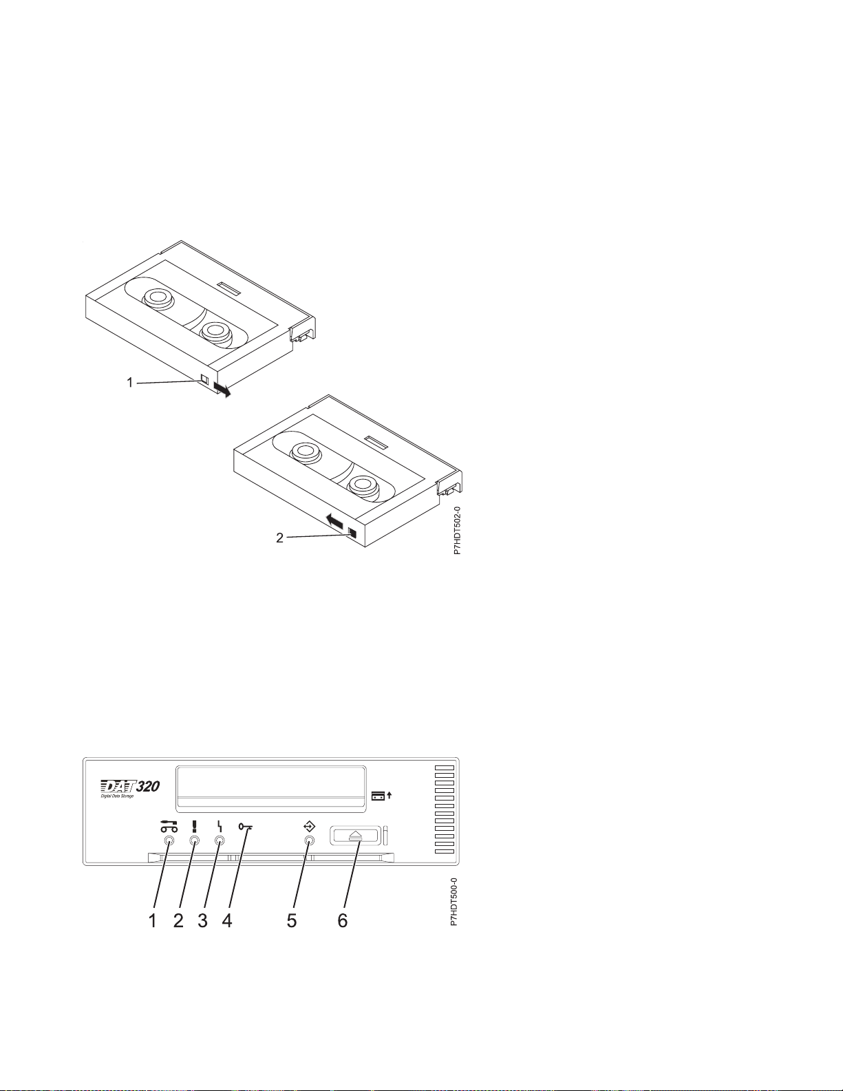
Setting the write-protect switch (FC 5661)
You might need to set the write-protect switch on your tape drive. Use the information in this topic to
perform this task.
Attention: Do not attempt to change the write-protect settings after the tape cartridge is loaded in the
drive because this might cause unpredictable results and might damage the tape or the drive.
The position of the write-protect switch on the tape cartridge determines when you can write to the tape.
1 When the switch is set to the right, data can be written to and read from the tape.
2 When the switch is set to the left, data can only be read.
Status lights (FC 5661)
You might need to read the status lights on your tape drive to determine the operating status of the
drive. Use the information in this topic to perform this task.
The following illustration is a front view of the tape drive:
Figure 8. Front view of tape drive
1 Cleaning LED (amber)
2 Media fault LED (amber)
64 Power Systems: Managing devices
Page 77

3 Drive fault LED (amber)
4 Encrypt LED (blue)
5 Ready/Activity LED (green)
6 Unload/Reset button
The combinations of the lights and their definitions are shown in the following table.
Table 29. Definition of status light combinations
Ready/
Activity
(green)
Flash_2Hz or
on or off
Activity
Cleaning
(amber)
Tape fault
(amber)
Drive fault
(amber)
Encrypt fault
(blue)
Power on LED test (5 seconds) On On On On On
Power on self-test (POST) activity Off Off Off Off Flash_2Hz
POST failed Off Off Flash_2Hz Off Off
1
POST passed On
or off Off Off Off Off
Data cartridge
Loading On
Loaded, no activity On
Loaded, activity On
Unloading On
Ejected On
1
or off Off Off
1
or off On2or off
1
or off On2or off
1
or off On2or off
1
or off On2or off
Flash_2Hz
Flash_2Hz
Flash_2Hz
Flash_2Hz
off
off
off
off
8
4
or
4
or
4
or
4
or
Off Flash_2Hz
Off On
Off Flash_2Hz
Off Flash_2Hz
Off Off
Cleaning cartridge
4
Loading, cleaning, unloading On Off
Ejected, clean success Off Off
Ejected, clean failure On
1
On
Flash_2Hz
Flash_2Hz
3
Flash_2Hz4or
off
off
off
or
4
or
Off Flash_2Hz
Off Off
Off Off
Unrecoverable media failure On On Off Off
Firmware download
Unload (if cartridge present) See: Data Cartridge Unloading
Download and reprogram Flash_8Hz Off Off Off Flash_8Hz
Reset (5 seconds) On On On Off On
Self-tests See Power on self-test activity, and then see either POST passed or POST failed.
Firmware download fail
Note: This is cleared when other
activity occurs
10
5
Off Off Flash_2Hz Off Off
Diagnostic tape test
Eject initiated primed drive to
treat inserted data cartridge as
Normal Normal Normal Off Flash_4Hz
diagnostic tape
Chapter 2. Managing tape drives 65
Page 78

Table 29. Definition of status light combinations (continued)
Ready/
Activity
(green)
Activity
Cleaning
(amber)
Tape fault
(amber)
Drive fault
(amber)
Encrypt fault
(blue)
In progress See Data cartridge: Loaded, activity
Initiated by SCSI
diagnostic using
normal data tape
Passed
Failed
7
6
See Data cartridge: Loaded, no activity
On On On Normal Flash_4Hz
Until tape ejected. See Data cartridge: ejected
In progress See Data cartridge: loading
Flash_4Hz Off Off Normal Flash_4Hz
Using tape with
diagnostic tape
recognition holes
Passed
ejected
Failed
9
, tape
6
Off Off Off Normal Flash_4Hz
See Data cartridge: ejected
On On On Normal Flash_4Hz
See Data cartridge: ejected
Encryption related
No encryption or decryption
activity
11
Normal Normal Normal Off Normal
Encryption parameters are loaded;
the drive is ready to read/write
Normal Normal Normal On Normal
encrypted data
Drive is reading/writing
encrypted data
Normal Normal Normal Flash_2Hz Flash_2Hz
Encryption parameters loaded, but
the drive is reading/writing
Normal Normal Normal On Flash_2Hz
unencrypted data.
Encryption related error exists Normal Normal Flash_4Hz Flash_4Hz Normal
66 Power Systems: Managing devices
Page 79

Table 29. Definition of status light combinations (continued)
Cleaning
Activity
1
CLEAN_LED activation in this state means the drive needs cleaning. It will be set due to hard or soft errors. It is
(amber)
Tape fault
(amber)
Drive fault
(amber)
Encrypt fault
(blue)
Ready/
Activity
(green)
cleared upon successful cleaning cartridge usage. State is preserved over a power cycle.
2
TAPE_LED activation in this state can only be due to a repeated hard or soft error. It is cleared when data or
cleaning cartridge is inserted.
3
TAPE_LED activation in this state can only be due to a cleaning cartridge failure. It is cleared when data or
cleaning cartridge is inserted.
4
DRIVE_LED activation in this state can only be due to the media management algorithm determining that the
drive has a serious problem with regard to its write/read performance. It is not preserved over power cycle.
5
The firmware download failed. The firmware download should be retried.
Note: This does not happen if the problem is simply due to an incorrect firmware image being attempted, for
example, the DAT72 image being downloaded to DAT160. The purpose of this LED sequence is to show the user
that the download failed and to retry the download. Examples of this are if the host failed to send all the data or if
the hardware was unable to complete the task. This sequence is not activated if the microcode headers are invalid
or if the code fails its checksum.
6
The LED states for SCSI/tape diagnostic failed remain until the ejection is completed and then either the Eject
button is pressed or another tape is inserted.
7
The LEDs revert to nondiagnostic tape state (for example, for a loaded data tape).
8
If the drive LED is on, the tape load is not initiated.
9
The LED states for tape diagnostic passed remain until the auto-eject operation is completed.
10
The firmware download failed LEDs continue to show until another change to the LEDs is required that is due to
either cartridge loading or unloading or due to tape motion. So it is not SCSI commands, as such, that clear this but
the response of the LED display to those SCSI commands. Tape access commands cause cartridge or tape motion to
occur.
11
IBM does not support encryption in their systems, but the LED activity is included in the event that a user inserts
a tape with encrypted data.
Tape cartridges (FC 5661)
Learn about the types of tape cartridges that are available for this drive.
Available tape cartridges
Table 30. 4 mm data cartridges
IBM part number Type of cartridge
46C1936 DAT320 160 GB Data Cartridge
46C1938 4 mm Test Cartridge
46C1937 4 mm Cleaning Cartridge
Most bulk eraser devices do not have the capability to erase the 4 mm data cartridge.
Chapter 2. Managing tape drives 67
Page 80

Resetting the tape drive
You might need to reset your tape drive. Use the procedure in this topic to perform this task.
Use this information to reset your tape drive, without affecting server operation. Allow up to 2 minutes
for the entire tape drive process to complete.
Attention: Resetting a tape drive before the current backup operation has completed can cause loss of
customer data.
To reset the tape drive, follow these steps:
1. Press and hold the eject button for 20 seconds, and then release the button. The LEDs on the drive
will be flashing while the reset function is in process.
2. When the LEDs stop flashing, wait approximately one minute for the drive to complete the reset
operation. The drive will then be ready to use.
68 Power Systems: Managing devices
Page 81

Chapter 3. Managing DVD drives
Learn about using and managing removable media devices. Find specifications and installation notes for
specific drives.
SATA Slimline DVD-RAM Drive (FC 5762)
Learn about the specifications of this DVD-RAM drive.
The serial advanced technology attachment (SATA) Slimline DVD-RAM Drive is an internal, low profile
DVD-RAM drive that is capable of reading and writing 4.7 GB DVD-RAM discs, as well as reading a
multitude of other optical media discs. This drive reads type II (removable from cartridge) DVD-RAM
discs. The drive also reads CD-ROM, CD-R, CD-RW, DVD-R, DVD+R, DVD-RW, and DVD+RW. System
boot and installation functions are supported with CD and DVD media.
Specifications
v FRU part number: 44V4220
v Custom card identification number (CCIN): 6331 model 004
Note: The model field is subject to change.
v Media:
– Reads CD-ROM, CD-R, CD-RW, DVD-ROM, DVD-RAM, DVD-R, DVD+R, DVD-RW, and DVD+RW
discs
– Writes 4.7 GB DVD-RAM discs
v Interface: SATA
v Connector: Slimline SATA
v Connector: SATA
v Loading tray: supports 12 cm and 8 cm discs
v Operating positions: vertical or horizontal (8 cm discs require horizontal operation)
v Form factor: 12.7 mm Slimline
v DVD video: not supported
v AIX 5.1 only reads CD-type formatted DVD media
v Requirements: 1 Slimline media bay
Related reference
“Opening a DVD tray manually” on page 70
Under usual conditions, the tray automatically opens when you press the Load/Unload button. If it does
not automatically open, you can use the emergency eject feature to open the tray manually.
“DVD-RAM type II disc” on page 70
The DVD-RAM type II disc can be removed from its cartridge and played in a DVD-ROM or DVD-RAM
drive that is compatible with the DVD-RAM type II disc.
Handling and storing the DVD media
Learn how to handle and store the DVD media.
DVD media must be handled with care. Leaving the media exposed allows dirt particles to accumulate
and to become a source of contamination. Handling the DVD media with care reduces errors and
improves the performance.
© Copyright IBM Corp. 2010 69
Page 82

Restrictions on using DVD media
Correct ways to handle DVD media:
1. Handle media by the outer edge or the center hole.
2. Store media in jewel cases specified for DVDs.
3. Return media to storage cases immediately after use to minimize the effects of environmental changes.
4. Store media in a cool, dry environment in which the air is clean.
5. Remove dirt, foreign materials, fingerprints, smudges, and liquids by wiping with a clean cotton
fabric in a straight line from the center of the disc toward the outer edge.
6. Check the media surface before recording.
Incorrect ways to handle DVD media:
1. Touch the surface of the media.
2. Bend the media.
3. Use adhesive labels on the media.
4. Expose media to extreme heat or high humidity.
5. Expose media to prolonged sunlight or other sources of ultraviolet light.
6. Write or mark in the data area of the media.
7. Clean by wiping in a circular direction going around the disc.
Opening a DVD tray manually
Under usual conditions, the tray automatically opens when you press the Load/Unload button. If it does
not automatically open, you can use the emergency eject feature to open the tray manually.
Follow these steps to manually open the tray:
1. Follow your operating system instructions for shutting down your system, then turn off the power to
your system unit. Unplug the power cord from the wall outlet.
2. Insert the straightened end of a paper clip into the emergency eject hole until you feel some
resistance.
3. Continue to push in the paper clip while you pull out the tray with your fingernail.
4. Pull the tray completely open and remove the disc. It is usual for the tray to make a clicking sound
while you are pulling it open.
DVD-RAM type II disc
The DVD-RAM type II disc can be removed from its cartridge and played in a DVD-ROM or DVD-RAM
drive that is compatible with the DVD-RAM type II disc.
Attention: Be careful when handling removed discs. Debris, dust particles, fingerprints, smears, or
scratches can affect recording and playback of discs. Do not use solvents to clean disc surfaces. To clean a
disc, use a soft, lint free cloth and gently wipe the disc surface outwards from the center hole to the outer
edge. Do not rub, make circular motions or try to follow the circular lines in the disc. When labeling a
disc, write only on the printed label side, using a soft felt-tip marker. Do not use a hard-tip pen to write
on disc surface. Keep out of direct sunlight, high temperatures, and humidity. Do not attach labels to
either side of the disc.
Removing a disc from the cartridge
To remove a disc from the cartridge, do the following steps:
Note: Handle the disc only by its edges.
70 Power Systems: Managing devices
Page 83

1. Use the tip of a ballpoint pen to push the locking pin up and out of the disc cartridge.
2. Use the tip of a ballpoint pen to push down on the lock button while pulling the cartridge lid open.
3. With the cartridge lid open, slide the disc out of the cartridge.
drive.OnlyforplaybackinDVD-ROMdrivescompatiblewithDVD-RAM.
drive.OnlyforplaybackinDVD-ROMdrivescompatiblewithDVD-RAM.
TheDVD-RAMT
TheDVD-RAMT
1
2
3
1 Locking Pin
2 Lock Button
3 Cartridge Lid
Returning a disc to the cartridge
To return a disc to the cartridge, do the following steps:
Notes: Both the disc label and the cartridge label should be facing up. Handle the disc only by its edges.
1. Slide the disc into the cartridge.
2. Close the cartridge lid. Make sure the lock button snaps into position.
3. Install the locking pin.
Chapter 3. Managing DVD drives 71
Page 84

72 Power Systems: Managing devices
Page 85

Chapter 4. Managing diskette drives
Learn about the features of specific diskette drives.
External USB 1.44 MB diskette drive (FC 2591)
Learn about the features of this media device.
The following provides information about the external USB 1.44 MB diskette drive.
Installation
and
removal
Description The externally attached USB diskette drive provides storage capacity up to 1.44 MB on a high-density
To install this external USB 1.44 MB diskette drive, complete the following steps:
1. Unpack the device and ensure you have all the cables and parts.
2. Connect the USB cables to an available USB port on the system unit.
3. Wait for the system to recognize the new device (approximately 1-3 minutes).
To remove this external USB 1.44 MB diskette drive, complete the following steps:
1. Ensure you complete any processes running from or to the diskette drive.
2. Eject any diskette you have in the device.
3. Disconnect the device from the system unit.
If you are installing this device on system unit or partition running the AIX operating system, you can
refer to the manual at the following URL: USB 1.44 MB External Diskette Drive Installation and Using
Guide http://publib16.boulder.ibm.com/pseries/en_US/infocenter/base/hardware_docs/pdf/
231332.pdf
If you are installing this device on a system or partition running any other operating system, see the
documentation for that operating system.
(2HD) diskette and 720 KB on a double-density diskette. Includes 350mm (13.7 in) captured cable with
standard USB connector.
Limitations:
v Maximum 1 USB diskette per adapter
v Up to 1 Keyboard and Mouse also supported on the adapter with the diskette drive at the same
time
v No system boot capability
v Not to be operated upside down or with eject button down
Characteristics:
v FRU part number: 033P3339
v Capacity - 1.44 MB (2HD disk) or 720 KB (double-density disk)
v Physical Dimensions: Width=103mm (4.05 in), Height=17.6mm (.69 in), Depth=141.8-mm (5.58 in)
v Color: Black
v Data Rate: 12 Mbits/sec
v Maximum Power Consumption: 2.36 Watt (seek)
v Operates in all positions except those noted in the preceding limitations
v Attributes provided: External diskette drive
v Attributes required: 1 available USB port
© Copyright IBM Corp. 2010 73
Page 86

74 Power Systems: Managing devices
Page 87

Chapter 5. Managing disk devices
Find information to effectively manage your disk units, disk pools, and independent disk pools for the
IBM i operating system. Find information to help you protect the data on your disk units, including
information about using hot-spare device parity protection.
© Copyright IBM Corp. 2010 75
Page 88

76 Power Systems: Managing devices
Page 89

Chapter 6. Managing removable disk drives
Learn about using and managing removable disk drives. Find specifications and installation notes for
specific drives.
USB Removable Disk Drive (FC 1103, 1104, 1106, 1107)
Learn about the features of this drive.
Description
The USB Removable Disk Drive consists of a docking station, which holds a removable disk drive. The
docking station is available as an internal or external device. The disk drive is a backup and restore
device that can be used as an alternative to tape drives. The removable disk drive is not a replacement
for regular disk drives and cannot be used as part of a disk array. The following illustrations show the
internal and external drives.
Figure 9. Internal drive, front view
A Emergency eject hole
B Cartridge indicator light
C Eject button and power indicator light
Figure 10. External drive, front view
© Copyright IBM Corp. 2010 77
Page 90

D Write-protect switch
Figure 11. Internal drive, rear view, and connectors
E Power connector
F USB connector
Figure 12. External drive, rear view, and connectors
78 Power Systems: Managing devices
Page 91

E Power connector
F USB connector
Feature codes and part numbers
Learn about the feature codes (FCs) and part numbers for the USB Removable Disk Drive.
FC 1103 - USB Internal Docking Station for Removable Disk Drive
FC 1103 uses an internal USB cable to connect to the internal USB port on the control panel of a
system that supports this feature. The USB and power cable are included in the feature code.
FC 1103 provides the following parts:
46C5370 (FRU: 46C5380) - USB Internal docking station
46K7435 - Internal USB cable (12 inch)
46K7434 - Internal power cable (11 inch) with right angle power connector
44V3429 - Two drive slide assembly rails
1621187 - Four flat blade screws
FC 1104 - USB External Docking Station for Removable Disk Drive
FC 1104 uses an external USB cable to connect to an external USB port. The 1104 feature code
includes a USB cable, external power supply, and power cord as part of the feature code.
FC 1104 provides the following parts:
46C5381 - USB external docking station
44E8889 - External USB cable
49Y9890 - External power supply with power cord and universal plugs for all supported
geographies
39M5516 - Power cord (1 m) from the power supply to the rack power distribution unit
Removable disk drives
Table 31. Removable disk drives
Feature Code Part number Description
1106 46C5375 160 GB Removable Disk Drive
No feature code 46C5394 320 GB Removable Disk Drive
1107 46C5395 500 GB Removable Disk Drive
Purchasing additional removable disk drives
For best results, use only the removable disk drives that are shown in Table 31.
Chapter 6. Managing removable disk drives 79
Page 92

The removable disk drives are a supply item that can be ordered as a feature code. To order in the United
States and Canada, call 1-888-IBM-MEDIA. To order drives in other locations, contact your local provider
of IBM storage products or visit the following Web site: http://www.storage.ibm.com/media/.
Removable disk drives are not a service item and IBM service representatives are not dispatched to
service or replace removable disk drives.
Storing removable disk drives
Store removable disk drives in their protective containers, on a flat surface with the top side up. The
storage area must be clean, dry, normal room temperature, and away from any magnetic fields. For best
storage life, use the removable disk drives every six months.
Supported USB adapters and cables
Attention: The docking station only supports the USB cable that is provided as part of the feature code.
The docking station does not support attachment using USB hubs, add-on USB cables, or USB cable
extenders.
The external docking station can be connected to the external, integrated USB ports on POWER7 systems
or to the USB ports on 4-Port USB PCI Express
®
Adapter (FC 2728).
The internal docking station can be connected to the internal USB port on the control panel of POWER7
systems.
Note: When the USB port on the control panel is used for the docking station, that port is disabled for
other uses.
Specifications
Interface
USB 2.0
Mksysb
Yes
Bootable
Yes
Physical form factor (internal docking station)
5.25 inch half high
Environmental
USB Removable Disk Drive Operating conditions Nonoperating conditions
Temperature 5 -55°C –40 -65°C
Relative humidity 8 -90% noncondensing 5 -95% noncondensing
Maximum wet bulb temperature 29.4°C noncondensing 40°C noncondensing
Maximum temperature gradient 20°C per hour 20°C per hour
Altitude –300 -3048 m (10,000 ft) –300 -12,192 m (40,000 ft)
Supported operating systems
USB Removable Disk Drive is supported on the following versions of the AIX and Linux®operating
systems:
v AIX 5L Version 5.3 with the 5300-11 Technology Level, or later
80 Power Systems: Managing devices
Page 93

v AIX Version 6.1 with the 6100-04 Technology Level, or later
v Red Hat Enterprise Linux version 3 Update 7, or later
v SUSE Linux Enterprise Server 10, or later
Using the USB Removable Disk Drive for backup and restore
The disk drive is a backup and restore device that can be used as an alternative to tape drives. The
removable disk drive is not a replacement for regular disk drives and cannot be used as part of a disk
array.
Note: If power is lost during a backup to the disk, the data can be compromised. Verify the data or rerun
the backup.
Using the drive with AIX
AIX names the drive usbmsx. For example, usbms1 and usbms2. AIX also can use the device as a raw
device. For example, rusbms1 and rusbms2.
AIX uses the removable disk drive differently depending on the program being used. The AIX mksysb
command builds a list of files to back up, creates a universal disk format (UDF) file system, and puts a
boot image and the root volume group on the removable disk drive. When the mksysb process is
complete the removable disk drive can be used to boot the system. If you mount the removable disk
drive, you can display and copy files to and from the UDF file system on the removable disk drive.
The AIX tar, backup, restore, dd, and cpio commands can write to the removable disk drive as a raw
device or non raw device. You might get improved performance by using the device as a raw device.
See the AIX documentation for additional information.
Using the drive with Linux
Linux configures the drive as a disk drive with a name in the format sdx, for example, sda, sdb, and sdc.
See the Linux documentation for information about using Linux copy and backup commands.
Setting the write-protect switch
The removable disk drives have a red, write-protect tab that is located on the back of the drive. To
write-protect a drive, slide the write-protect tab toward the lock symbol. To disengage write protection,
slide the tab to the unlock symbol.
Using the emergency eject function
To eject a removable disk drive, press the eject button. If a drive is stuck, follow these steps:
1. If you using the internal docking station, power off the system. If you are using the external docking
station, unplug the power cable from the device.
2. Insert a large straightened paper clip (or similar object) into the emergency eject hole. Do not insert
the object in the hole at an angle. Keep the object straight and apply some force to eject the drive.
3. When the drive has been ejected by the docking station, grasp the exposed sides of the drive and pull
the drive straight out.
4. Restart your system to reset the docking station. If you are using the external docking station,
reconnect the power cable for the docking station and then restart the system.
Chapter 6. Managing removable disk drives 81
Page 94

Status lights
Learn about the power indicator and drive indicator status lights on the USB Removable Disk Drive.
Power indicator
The eject button is illuminated by a power indicator light. The following table describes the operation of
the power indicator.
Table 32. Power indicator
Indicator status Meaning Description
Off No power Docking station does not have power.
Steady green Ready Power is on and the docking station
is working correctly.
Flashing green Ejecting Cartridge is ejecting.
Flashing amber Fault Docking station has detected a fault
condition with the docking station.
Removable disk drive indicator
The disk drive has an indicator light that displays the status of the drive. The following table describes
the operation of the drive indicator.
Table 33. Cartridge indicator
Indicator status Meaning Description
Off Not ready Drive is not inserted correctly or the
docking station has no power
Steady green Ready Drive is ready
Flashing green Activity Drive is reading, writing, or seeking
Flashing amber Fault Docking station has detected a fault
condition with the cartridge
Installing the docking station for the removable disk drive
For comprehensive installation instructions, see the Media devices topic.
Keep in mind the following points when you install FC 1104, the USB External Docking Station for
Removable Disk Drive:
v A rack shelf is not included with FC 1104.
v The docking station can be rested on a flat surface in a rack or on a table top next to a rack.
v Ensure that the device is on a flat surface, is right side up, and is not likely to be bumped, dropped, or
otherwise damaged or jolted.
v If the docking station is placed by itself on a rack shelf, it will have space on the sides of the device.
No filler panels are provided with the docking station.
v If the docking station is placed on a rack shelf, ensure that the docking station has sufficient air flow
but that is does not affect the air flow of the other systems in the rack.
v Do not block the fan on the back of the docking station.
82 Power Systems: Managing devices
Page 95

Chapter 7. Managing communications devices
Learn about the LAN-Attached Remote Asynchronous Node (RAN) 16 (model 7036-P16).
LAN-Attached Remote Asynchronous Node 16 (model 7036-P16)
Learn about installing, removing, replacing and managing the LAN-Attached Remote Asynchronous
Node (RAN) 16 (model 7036-P16).
Note: Additional information can be found on the software CD provided with this device.
7036-P16 description and overview
Learn about the product description, characteristics, and throughput considerations for this device.
Product description
The 7036-P16 is a 16-port EIA-232 LAN-Attached Remote Asynchronous Node (RAN) for IBM System p
servers. The 7036-P16 provides connectivity to asynchronous EIA-232 devices, such as modems, terminal
type (tty) terminals, printers, and so on.
The 7036-P16 can be used in a rack-mounted or table-top configuration. Hardware to mount the 7036-P16
in a rack or to use on a table top is included in the package. When installed in a rack, take care with
routing the cables to ensure the cables do not interfere with other devices mounted in the rack.
The 7036-P16, when used with Digi RealPort software, will convert the serial data stream to and from
attached asynchronous EIA-232 devices into TCP/IP traffic. After the data is on the TCP/IP network, a
host system attached to the same network can treat the attached devices as if the devices were connected
directly to the host system.
Product characteristics
Electromagnetic Compatibility (EMC) Certifications:
v FCC Rules Part 15, Subpart B, Class A limit
v EN61000-3-2:2000 and EN61000-3-3:1995 + Amendment A1:2001
v EN55022: 1998 + Amendment 1:2000 Class A
v AS/NZS CISPR 22.2002
v Japan VCCI V3.2001.04
v ICES-003, Class A
v EMC Directive 89/336/EEC (CE Mark) consisting of EN55024 1988
v Australian EMC Framework (C-Tick Mark) consisting of AS/NZS CISPR 22:2002
®
Safety:
v UL CD certified to EN60950 3rd Edition
v CSA C22.2 No 60950
v UL recognized to UL60950 3rd Edition
Physical characteristics:
v Physical Dimensions: (16.8in./42.7cm)x(6.6in./16.76cm)x(1.6in./4.06cm)
v Weight: 7.05 lb./3.2 kg
© Copyright IBM Corp. 2010 83
Page 96

Environmental Limits:
v Operating
– Temperature: 0 to 40 C (ambient air temperature)
– Humidity: 5% to 95% (non-condensing)
– Wet Bulb: 29 C
– Altitude: 0 - 7000 ft
v Storage
– Temperature: 1 to 60 C
– Humidity: 5% to 80% (non-condensing)
– Wet Bulb: 29 C
v Shipping
– Temperature: -40 to 60 C
– Humidity: 5% to 100% (non-condensing)
– Wet Bulb: 29 C
Power Consumption
Table 34. 7036-P16 power consumption
Voltage (input) Current (amp) Watt
100/250VAC nominal 0.8 A Maximum 12 W typical
90/264VAC maximum 40A in rush
47/63 Hz 2A fuse
Throughput considerations
The limits on throughput are a function of the network and the server or server partition to which the
7036-P16 ports are configured.
System port throughput:
The 7036-P16 supports full-duplex operation up to 230K bps on all ports. Operation with all sixteen ports
running full-duplex at 230K bps is supported.
Network throughput:
The 7036-P16 is an Ethernet attached device and as such, any number may be attached to a given
network. However, attaching more devices to any network reduces the overall network throughput and
care must be taken to not overload any given network.
Testing has shown that as many as eight 7036-P16 devices may be attached to a network without
adversely affecting network throughput. Eight 7036-P16 devices will support up to 128 asynchronous
EIA-232 connections. More devices may be attached, but network performance may be adversely affected.
Server or partition throughput:
Each 7036-P16 provides 16-Ports of asynchronous EIA-232 connectivity over a 10/100 Ethernet port at
speeds up to 230K bps. Given that any number of 7036-P16s may be attached to a server or partition, a
single server or partition could in effect have a very large number of asynchronous EIA-232 connections
that could adversely affect any single server or partition.
84 Power Systems: Managing devices
Page 97

Installing 7036-P16 hardware
You might need to install this hardware. Use the procedure in this section to perform this task.
The following information describes the materials and procedures for installing this device. A Phillips
screwdriver is required to complete the installation of this unit.
Before you install the 7036-P16 unit, verify that the hardware package contains the following items:
v 7036-P16 unit
v 7036-P16 software and documentation CD
v 7036-P16 Quick Setup Guide
v Brackets to mount 7036-P16 on rack
v Rubber feet for tabletop usage
v Power cord (North American 120 V ac use only)
v RJ-45 to DB25 serial cable DB25 wired per EIA-232 specification
v RJ-45 to DB09 serial cable DB09 matches pin configuration on existing DB09 system ports on IBM
System p systems
v RJ-45 wrap plug for diagnostics.
Installing the deskside 7036-P16 unit
To install the deskside 7036-P16 unit, do the following steps:
1. Unpack the hardware.
2. Remove the rubber feet from the plastic bag.
3. Attach the rubber feet to the bottom of the 7036-P16 in the locations indicated.
4. Attach the power cord. A power cord for use in North America is provided.
5. Use an Ethernet cable to connect the 7036-P16 to the network.
6. Connect serial devices as needed.
Installing the rack-mounted 7036-P16 unit
To install the rack-mounted 7036-P16 unit, do the following steps:
1. Unpack the hardware.
2. Remove the right-angle brackets and screws from the plastic bag.
3. Use a Phillips screw to attach the brackets in the predrilled holes on the sides of the 7036-P16.
4. Mount the 7036-P16 in the same location from which the 7036-P16 was removed.
5. Attach the power cord. A power cord for use with 120 V ac is provided.
Optional rack power cord feature codes (FC) are available to connect the 7036-P16 to the rack Power
Distribution Unit (PDU). These cords come in various lengths. They are identified by the following
feature codes:
v FC 6458: Power Cord (14-foot), Drawer to IBM PDU, 250V/10A
v FC 6672: Power Cord (9-foot), Drawer to IBM PDU, 250V/10A
v FC 6671: Power Cord (5-foot), Drawer to IBM PDU, 250V/10A
The previous features are only available for use in racks less than 25U in size.
6. Use an Ethernet cable to connect the 7036-P16 to the network.
7. Connect serial devices as needed.
Chapter 7. Managing communications devices 85
Page 98

Installing Digi RealPort software for the 7036-P16 device
You might need to install the Digi RealPort software on an AIX or Linux host server. Use the procedure
in this section to perform this task.
Digi RealPort software-support packages
The following is a list of the software packages available on the software CD provided with the 7036-P16
unit:
v The Digi RealPort software package for AIX supports the following AIX levels:
™
– AIX 5L
– AIX 5L 5.3.0.30 (and later)
v The Digi RealPort software package for Linux supports the following Linux levels:
– Linux Red Hat Version RHEL4, Update 3
– Linux SUSE Version SLES 9 SP2
Installing the Digi RealPort software
To install the Digi RealPort software, do the following steps:
1. Install all updates and packages required to bring the operating system to the supported levels.
2. Install all Linux packages required to compile and create binaries from the Digi RealPort Software
source code.
The following is a list of Linux packages that are required to install the Digi RealPort software:
v gcc
v gcc-64bit
v gcc-c++
v gcc-g77-64bit
v gcc-info
v gcc-locale
v gcc-objc
v gcc-objc-64bit
v kernel sources
v glibc-devel-64bit
v ncurses-64bit
v ncurses-devel
3. Install the Digi RealPort software. To install the software, see the following procedures.
5.2.0.75 (and later)
Installing the AIX Digi RealPort software
To install the software package for the AIX environment, do the following steps:
1. Log in to the host server as the root user.
2. Insert the CD-ROM into the CD-ROM drive.
3. Type the following command: smitty install_all
4. Press F4.
5. Select digiasync, then press Enter.
6. Use the cursor to scroll to ACCEPT new license agreement
7. Press F4.
8. Select Yes, then press Enter.
86 Power Systems: Managing devices
Page 99

When installation commences, do not interfere until the installation completes. A successful
installation will return an OK message. An unsuccessful installation will return a FAILED message.
If you receive an OK message, continue to the next step. If you receive a failed message, review the
smit.log file to determine why the installation failed.
9. Press F10.
10. Type: lslpp -l | grep digi
If the Digi RealPort package installed correctly, you will receive a message. The following are
examples of return messages:
v digiasync.realport.obj 3.8.7.0 COMMITTED Digi RealPort Driver
v digiasync.realport.obj 3.8.7.0 COMMITTED Digi RealPort Driver
11. After the Digi RealPort Software is installed, the user may configure the 7036-P16 onto the network,
if it is not already configured. For instructions on how to perform the network configuration, see
“Configuring the 7036-P16 into the network” on page 90.
Installing the Linux SUSE Digi RealPort software
To install the software package for the Linux SUSE environment, do the following steps:
1. Log in to the server as the root user.
2. If the CD-ROM is already inserted and mounted, then proceed to step 5.
3. Insert the CD-ROM into the CD-ROM drive.
4. Type: mount -t auto /dev/cdrom /mnt
5. Type: cp /mnt/linux/40002086_M.src.rpm /usr/src/packages/SOURCES
6. Type: umount /mnt
7. Type: cd /usr/src/linux
8. Type: make mrproper
9. Type: make oldconfig
10. Type: cd /usr/src/packages/SOURCES
11. Type: rpmbuild --rebuild 40002086_M.src.rpm
12. Type: rpm -i /usr/src/packages/RPMS/ppc64/dgrp-1.9-6.ppc64.rpm
13. Type: rpm -qa | grep dgr
If the Digi RealPort Package installed correctly, the following is an example of the return message:
dgr-1.9.6
14. After the Digi RealPort software is installed, the user may configure the 7036-P16 onto the network,
if it is not already configured. For instructions on how to perform the network configuration, see
“Configuring the 7036-P16 into the network” on page 90.
Installing the Linux Red Hat Digi RealPort software
To install the software package for the Linux Red Hat environment, do the following steps:
1. Log in to the server as the root user.
2. If the CD-ROM is already inserted and mounted, then proceed to step 5.
3. Insert the CD-ROM into the CD-ROM drive.
4. Type: mount -t auto /dev/cdrom /mnt
5. Type: cp /mnt/linux/40002086_M.src.rpm /usr/src/packages/SOURCES
6. Type: umount /mnt
7. Type: cd /usr/src/packages/SOURCES
8. Type: rpmbuild --rebuild 40002086_M.src.rpm
9. Type: rpm -i /usr/src/packages/RPMS/ppc64/dgrp-1.9-6.ppc64.rpm
Chapter 7. Managing communications devices 87
Page 100

10. Type: rpm -qa | grep dgr
If the Digi RealPort Package installed correctly, the following is an example of the return message:
dgr-1.9.6
11. Afer the Digi RealPort software is installed, the user may configure the 7036-P16 onto the network, if
it is not already configured. For instructions on how to perform the network configuration, see
“Configuring the 7036-P16 into the network” on page 90.
Configuring the 7036-P16 device and tty
You might need to configure the 7036-P16 as a serial device on a host server. Use the procedure in this
section to perform this task.
The task consists of the following steps:
1. Configure the 7036-P16 as a serial device on a host server installed with one of the following
operating systems:
v AIX 5L 5.2.0.75, or later
v AIX 5L 5.3.0.30, or later
v Red Hat Enterprise Linux version 4, Update 3, or later
v SUSE Linux Enterprise Server 9, SP2, or later
This in effect binds the 7036-P16 to the host server.
2. Configure 7036-P16 system ports for use with Digi RealPort software.
Configuring a 7036-P16 device on an AIX host server
Assumptions:
v The target 7036-P16 and the host server are configured on an Ethernet network.
v The target 7036-P16 and the host server are attached to an Ethernet network.
v The Digi RealPort software is installed on the server.
Gather the following information:
v IP Address of the target 7036-P16: [7036-P16 IP Address]
v IP Address of the host server: [Host Server IP Address]
v Root password of target 7036-P16
Configure the 7036-P16 as a serial device on an AIX server:
1. Ensure that the 7036-P16 and the server are on the network. Ping the 7036-P16 by typing the
following command: ping -c 1 [IP Address of target 7036-P16]
If the 7036-P16 responds to the ping, then it is on the network and the user can proceed to the next
step. If the 7036-P16 does not respond to the ping, then the 7036-P16 is not on the network and the
user must perform the network configuration procedure, see “Configuring the 7036-P16 into the
network” on page 90.
2. Ensure that the Digi RealPort Software is installed on the server. Type the following command: lslpp
-l | grep digi
The response indicates that the digiasync.realport.obj file is installed.
Note: If the response indicates the Digi RealPort Software is installed then proceed to step 3. If there
is no response, then the Digi RealPort Software is not installed and the user must install the Digi
RealPort Software, see “Configuring the 7036-P16 into the network” on page 90.
3. Type: smitty devices
4. Use the cursor to select: Digi Device and Terminal Servers, then press Enter.
5. Use the cursor to select: Add a Digi Device and Terminal Servers , then press Enter
88 Power Systems: Managing devices
 Loading...