

Page 1

Brocade FCoE Switch Module for IBM
BladeCenter
Installation and User’s Guide
Page 2

Page 3

Brocade FCoE Switch Module for IBM
BladeCenter
Installation and User’s Guide
Brocade FCoE Switch Module for IBM BladeCenter: Installation and User Guide iii
Page 4

Note: Before using this information and the product it supports, read the general information in the IBM Warranty and Support Guide
and the IBM Safety Information and the IBM Systems Environmental Notices and User
Guide on the IBM Documentation CD.
First Edition (April 2010)
© Copyright International Business Machines Corporation 2010.
US Government Users Restricted Rights – Use, duplication or disclosure restricted by GSA ADP Schedule Contract with IBM Corp.
iv Brocade FCoE Switch Module for IBM BladeCenter: Installation and User Guide
Page 5

Contents
Safety
Chapter 1. Introducing the Brocade FCoE Switch Module
Components . . . . . . . . . . . . . . . . . . . . . . . . . . . . . . . . . . . . . . . . . . . . . 1
Dynamic Ports on Demand. . . . . . . . . . . . . . . . . . . . . . . . . . . . . . . . . . 2
Switch management . . . . . . . . . . . . . . . . . . . . . . . . . . . . . . . . . . . . . . . 2
Additional information. . . . . . . . . . . . . . . . . . . . . . . . . . . . . . . . . . . . . . 3
Related documentation . . . . . . . . . . . . . . . . . . . . . . . . . . . . . . . . . . . . 3
Inventory checklist . . . . . . . . . . . . . . . . . . . . . . . . . . . . . . . . . . . . . . . . 4
Notices and statements in this document . . . . . . . . . . . . . . . . . . . . . 5
Major components of the switch module . . . . . . . . . . . . . . . . . . . . . . 5
Chapter 2. Installing and replacing a high speed switch module
Installation guidelines . . . . . . . . . . . . . . . . . . . . . . . . . . . . . . . . . . . . . . . . . . . . . 9
System reliability guidelines. . . . . . . . . . . . . . . . . . . . . . . . . . . . . . . . . 9
Handling static-sensitive devices. . . . . . . . . . . . . . . . . . . . . . . . . . . . 10
Installing a switch module . . . . . . . . . . . . . . . . . . . . . . . . . . . . . . . . . . . . . . . . 10
Removing or replacing a switch module . . . . . . . . . . . . . . . . . . . . . . . . . . . . . 12
Chapter 3. Installing and removing an SFP+ module
Handling an SFP+ module . . . . . . . . . . . . . . . . . . . . . . . . . . . . . . . . . . . . . . . .15
Installing an SFP+ module . . . . . . . . . . . . . . . . . . . . . . . . . . . . . . . . . . . . . . . .16
Removing an SFP+ module. . . . . . . . . . . . . . . . . . . . . . . . . . . . . . . . . . . . . . . .17
Chapter 4. Cabling the switch module and the SFP+ module
Connecting the USB console cable . . . . . . . . . . . . . . . . . . . . . . . . . . . . . . . . .19
Disconnecting the USB console cable . . . . . . . . . . . . . . . . . . . . . . . . . . . . . . . 19
Connecting the SFP+ module cable. . . . . . . . . . . . . . . . . . . . . . . . . . . . . . . . .20
Disconnecting the SFP+ module cable . . . . . . . . . . . . . . . . . . . . . . . . . . . . . . 21
Connecting the RJ-45 Ethernet cable . . . . . . . . . . . . . . . . . . . . . . . . . . . . . . .21
Disconnecting the RJ-45 cable. . . . . . . . . . . . . . . . . . . . . . . . . . . . . . . . . . . . .22
Chapter 5. Information panels, LEDs, and external ports
© Copyright IBM Corp. 2010 v
Information panel . . . . . . . . . . . . . . . . . . . . . . . . . . . . . . . . . . . . . . . . . . . . . . .23
Information LEDs. . . . . . . . . . . . . . . . . . . . . . . . . . . . . . . . . . . . . . . . . . . . . . . .24
Switch module status LEDs . . . . . . . . . . . . . . . . . . . . . . . . . . . . . . . . 24
Port status LEDs . . . . . . . . . . . . . . . . . . . . . . . . . . . . . . . . . . . . . . . . .25
Page 6

POST activity . . . . . . . . . . . . . . . . . . . . . . . . . . . . . . . . . . . . . . . . . . . . . . . . . . .25
POST-operation LED indications. . . . . . . . . . . . . . . . . . . . . . . . . . . . .26
Chapter 6. Configuring the switch module
Establishing a TCP/IP session through the management module. . . . . . . . .28
Enabling management through external ports . . . . . . . . . . . . . . . . . . . . . . . .29
Configuring the switch module through the Telnet interface . . . . . . . . . . . . .30
Connecting to the switch module. . . . . . . . . . . . . . . . . . . . . . . . . . . .30
Accessing the main menu . . . . . . . . . . . . . . . . . . . . . . . . . . . . . . . . .30
Configuring the switch module through the mini-USB interface . . . . . . . . . . 31
Connecting to the switch module using Web Tools. . . . . . . . . . . . . . . . . . . . .31
Initial configuration . . . . . . . . . . . . . . . . . . . . . . . . . . . . . . . . . . . . . . . . . . . . . .32
Logging in to the switch module. . . . . . . . . . . . . . . . . . . . . . . . . . . . . . . . . . . .32
Configuring for FCoE . . . . . . . . . . . . . . . . . . . . . . . . . . . . . . . . . . . . . . . . . . . . .32
Backing up the configuration . . . . . . . . . . . . . . . . . . . . . . . . . . . . . . . . . . . . . .33
Resetting the Brocade FCoE Switch Module to factory defaults . . . . . . . . . .34
Chapter 7. Understanding Access Gateway
Disabling and enabling Access Gateway mode. . . . . . . . . . . . . . . . .36
Chapter 8. Updating the firmware
Determining the level of switch module firmware . . . . . . . . . . . . . . . . . . . . . .39
Obtaining the latest level of switch firmware. . . . . . . . . . . . . . . . . . . . . . . . . .39
Downloading the firmware . . . . . . . . . . . . . . . . . . . . . . . . . . . . . . . . . . . . . . . .40
Resetting and restarting the switch module . . . . . . . . . . . . . . . . . . . . . . . . . . 40
Chapter 9. Parts
Chapter 10. Solving problems
Running POST . . . . . . . . . . . . . . . . . . . . . . . . . . . . . . . . . . . . . . . . . . . . . . . . . .43
POST errors . . . . . . . . . . . . . . . . . . . . . . . . . . . . . . . . . . . . . . . . . . . . . . . . . . . .43
Appendix A. Getting help and technical assistance
Before you call . . . . . . . . . . . . . . . . . . . . . . . . . . . . . . . . . . . . . . . . . . . . . . . . . .45
Using the documentation . . . . . . . . . . . . . . . . . . . . . . . . . . . . . . . . . . . . . . . . .45
Getting help and information from the World Wide Web . . . . . . . . . . . . . . . .46
vi Brocade FCoE Switch Module for IBM BladeCenter: Installation and User Guide
Software service and support . . . . . . . . . . . . . . . . . . . . . . . . . . . . . . . . . . . . . 46
Hardware service and support . . . . . . . . . . . . . . . . . . . . . . . . . . . . . . . . . . . . .46
IBM Taiwan product service . . . . . . . . . . . . . . . . . . . . . . . . . . . . . . . . . . . . . . . 46
Page 7

Appendix B. Notices
Trademarks . . . . . . . . . . . . . . . . . . . . . . . . . . . . . . . . . . . . . . . . . . . . . . . . . . . . 47
Important notes . . . . . . . . . . . . . . . . . . . . . . . . . . . . . . . . . . . . . . . . . . . . . . . . .48
Electronic emission notices . . . . . . . . . . . . . . . . . . . . . . . . . . . . . . . . . . . . . . .49
Federal Communications Commission (FCC) statement . . . . . . . . .49
Industry Canada Class A emission compliance statement . . . . . . . 49
Avis de conformité à la réglementation d’Industrie Canada . . . . . . 49
Australia and New Zealand Class A statement . . . . . . . . . . . . . . . . . 49
CE statement. . . . . . . . . . . . . . . . . . . . . . . . . . . . . . . . . . . . . . . . . . . .49
United Kingdom telecommunications safety requirement. . . . . . . . 50
European Union EMC Directive conformance statement . . . . . . . . . 50
Germany Electromagnetic Compatibility Directive . . . . . . . . . . . . . .50
Japanese VCCI Class A statement . . . . . . . . . . . . . . . . . . . . . . . . . . . 51
Korean Class A warning statement . . . . . . . . . . . . . . . . . . . . . . . . . . 51
Russia Electromagnetic Interference (EMI) Class A statement . . . . 52
People's Republic of China Class A warning statement . . . . . . . . . .52
Taiwanese Class A warning statement . . . . . . . . . . . . . . . . . . . . . . . 52
Appendix C. Product Specifications
Switch components. . . . . . . . . . . . . . . . . . . . . . . . . . . . . . . . . . . . . . . . . . . . . .53
Weight and physical dimensions . . . . . . . . . . . . . . . . . . . . . . . . . . . . . . . . . . . 53
High speed switch module memory . . . . . . . . . . . . . . . . . . . . . . . . . . . . . . . . . 53
Environmental requirements . . . . . . . . . . . . . . . . . . . . . . . . . . . . . . . . . . . . . . 54
CNA support . . . . . . . . . . . . . . . . . . . . . . . . . . . . . . . . . . . . . . . . . . . . . . . . . . . .54
Fibre Channel Standards Compliance . . . . . . . . . . . . . . . . . . . . . . . . . . . . . . .54
Regulatory Compliance . . . . . . . . . . . . . . . . . . . . . . . . . . . . . . . . . . . . . . . . . . .55
Index
Brocade FCoE Switch Module for IBM BladeCenter: Installation and User Guide vii
Page 8

viii Brocade FCoE Switch Module for IBM BladeCenter: Installation and User Guide
Page 9

Safety
Pred instalací tohoto produktu si prectete prírucku bezpecnostních instrukcí.
Before installing this product, read the Safety Information.
Antes de instalar este produto, leia as Informações de Segurança.
Læs sikkerhedsforskrifterne, før du installerer dette produkt.
Lees voordat u dit product installeert eerst de veiligheidsvoorschriften.
Ennen kuin asennat tämän tuotteen, lue turvaohjeet kohdasta Safety Information.
Avant d’installer ce produit, lisez les consignes de sécurité.
Vor der Installation dieses Produkts die Sicherheitshinweise lesen.
Prima di installare questo prodotto, leggere le Informazioni sulla Sicurezza.
Les sikkerhetsinformasjonen (Safety Information) før du installerer dette produktet.
Antes de instalar este produto, leia as Informações sobre Segurança.
© Copyright IBM Corp. 2010 ix
Page 10
Antes de instalar este producto, lea la información de seguridad.
Läs säkerhetsinformationen innan du installerar den här produkten.
Important:
Each caution and danger statement in this document is labeled with a number. This number is
used to cross reference an English-language caution or danger statement with translated versions
of the caution or danger statement in the Safety Inf ormation document.
For example, if a caution statement is labeled “Statement 1,” translations for that caution
statement are in the Safety Information document under “Statement 1.”
Be sure to read all caution and danger statements in this document before you perform the
procedures. Read any additional safety information that comes with the server or optional device
before you install the device.
This device is intended for use with UL Listed IBM BladeCenters.
Statement 1:
DANGER
Electrical current from power, telephone, and communication cables is
hazardous.
To avoid a shock hazard:
• Do not connect or disconnect any cables or perform installation,
maintenance, or reconfiguration of this product during an electrical
storm.
• Connect all power cords to a properly wired and grounded electrical
outlet.
• Connect to properly wired outlets any equipment that will be attached
to this product.
• When possible, use one hand only to connect or disconnect signal
cables.
x Brocade FCoE Switch Module for IBM BladeCenter: Installation and User Guide
Page 11

• Never turn on any equipment when there is evidence of fire, water, or
structural damage.
• Disconnect the attached power cords, telecommunications systems,
networks, and modems before you open the device covers, unless
instructed otherwise in the installation and configuration procedures.
• Connect and disconnect cables as described in the following table
when installing, moving, or opening covers on this product or attached
devices.
To Conne ct: To Disconnect:
1. Turn everything OFF. 1. Turn everything OFF.
2. First, attach all cables to devices. 2. First, remove power cords from outlet.
3. Attach signal cables to connectors.. 3. Remove signal cables from
connectors.
4. Attach power cords to outlet. 4. Remove all cables from devices.
5. Turn device ON
Statement 2:
CAUTION:
When replacing the lithium battery, use only IBM® Part Number 33F8354 or an equivalent type
battery recommended by the manufacturer. If your system has a module containing a lithium
battery, replace it with only the same module type made by the same manufacturer. The battery
contains lithium and can explode if not properly used, handled, or disposed of.
Do not:
• Throw or immerse into water
• Heat to more than 100° C (212° F)
• Repair or disassemble
Dispose of the battery as required by local ordinances or regulations.
Statement 3:
xi
Page 12
CAUTION:
When laser products (such as CD-ROMs, DVD drives, fiber optic devices, or transmitters) are
installed, note the following:
Some laser products contain an embedded Class 3A or Class 3B laser diode.
Note the following.
Laser radiation when open. Do not stare into the beam, do not view directly
with optical instruments, and avoid direct exposure to the beam.
Class 1 Laser Product
Laser Klasse 1
Laser Klass 1
Luokan 1 Laserlaite
Appareil A` Laser de Classe 1
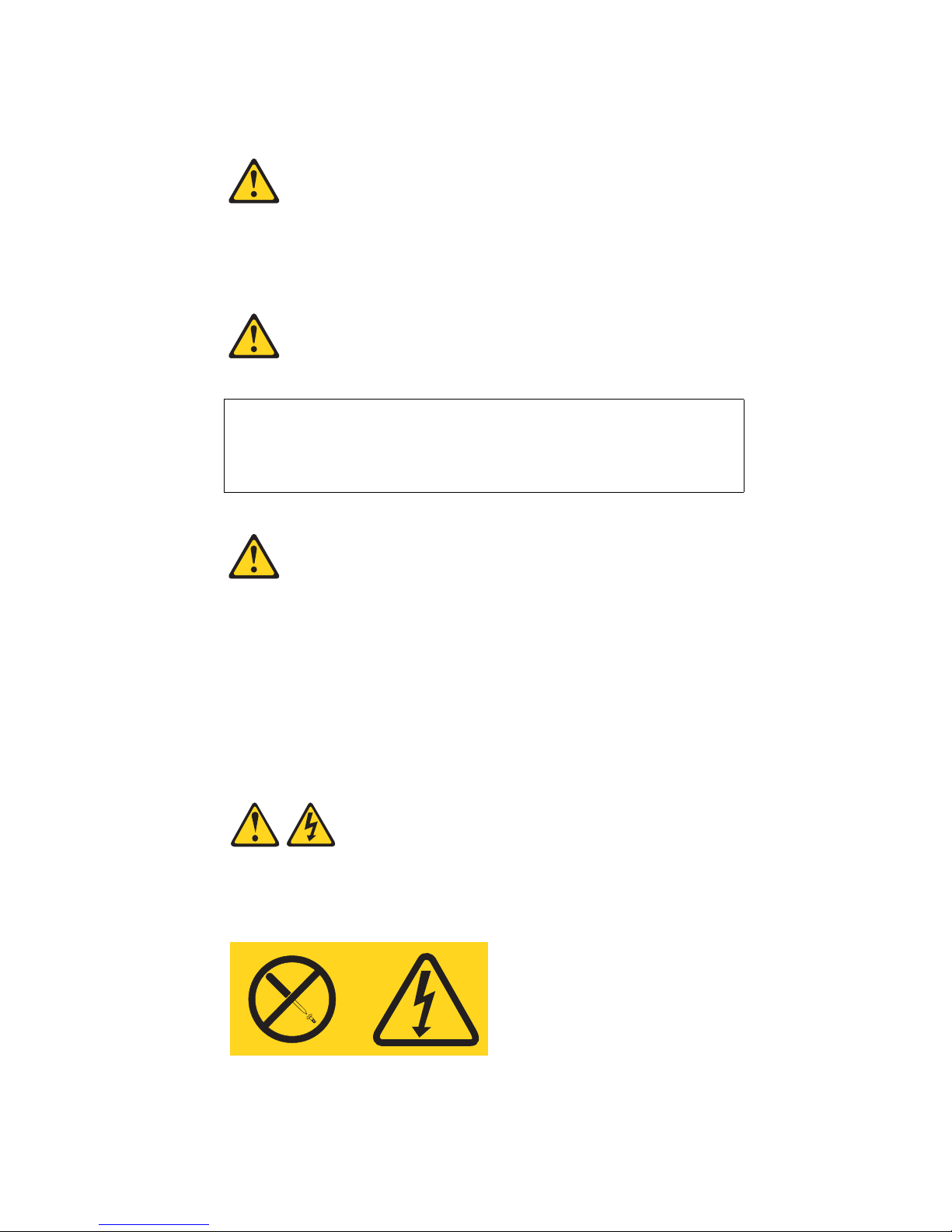
Statement 8:
CAUTION:
Never remove the cover on a power supply or any part that has the following label attached.
xii Brocade FCoE Switch Module for IBM BladeCenter: Installation and User Guide
Page 13

Hazardous voltage, current, and energy levels are present inside any component that has this label
attached. There are no serviceable parts inside these components. If you suspect a problem with
one of these parts, contact a service technician.
xiii
Page 14

xiv Brocade FCoE Switch Module for IBM BladeCenter: Installation and User Guide
Page 15

Chapter 1. Introducing the Brocade FCoE Switch Module
This Installation and User’s Guide contains the following instructions and information:
• Installing, removing, and replacing the high speed switch module
• Enabling the high speed switch module and its external ports
• Using the information panel, LEDs, and external ports on the high speed switch module
• Configuring the high speed switch module through a Telnet interface
• Configuring the high speed switch module through a Web browser interface
• Upgrading and expanding the functionality of the high speed switch module
• Performing basic troubleshooting tasks and solving problems with the high speed switch
module
• Getting help, service, and technical assistance
Important: This product is not intended to be connected directly or indirectly by any means
whatsoever to interfaces of public telecommunications networks.
Notes:
1. Throughout this document, including the references to screen contents, the Brocade FCoE
Switch Module is generically referred to as the high speed switch module, HSSM, or the switch
module. With respect to certain screen contents or titles, a high speed switch module might be
referred to as a switch module or switch, because the term switch module or switch appears
on those screens.
2. Unless otherwise stated, references to the BladeCenter unit apply to all BladeCenter units that
support the I/O module. As of the date of this document, the following devices are examples of
applicable BladeCenter units:
• BladeCenter H unit
• BladeCenter HT unit
3. Unless otherwise stated, references to the blade server apply to all blade servers that support
the high speed switch module and expansion card.
4. The illustrations in this document might differ slightly from your hardware.
5. The screens that are described or referenced in this document might differ slightly from the
screens that are displayed by your system. Screen content varies according to the type of
BladeCenter unit and the firmware versions and options that are installed.
6. Unless otherwise stated, references to the management module apply only to the BladeCenter
Advanced Management Module, which is the only type of management module that supports
the Brocade FCoE Switch Module.
Components
The Brocade FCoE Switch Module has the following components:
• Fourteen internal autonegotiating (1 Gbps to 10 Gbps) CEE ports, one connected to each of the
blade servers in the BladeCenter H unit (twelve internal ports in the BladeCenter HT chassis)
© Copyright IBM Corp. 2010 1
Page 16

• Two internal 100 Mb Ethernet ports to connect to the management module
NOTE
CAUTION
• Up to eight external 10 Gbps CEE ports for connecting small-form-factor pluggable (SFP+)
modules
• Up to eight external autosensing (2 Gbps, 4 Gbps, or 8 Gbps) Fibre Channel ports for
connecting SFP+ modules
• One external RS232 console port with a mini-USB interface for serial console management
• One external 10/100/1000 Mb RJ45 Ethernet copper port for debugging and field support
Dynamic Ports on Demand
The base version of the Brocade FCoE Switch Module ships with 16 licensed ports. Port activation
is through a process called Dynamic Ports on Demand (DPOD).
With DPOD, ports are licensed as they come online. In the base port set, two external CEE ports
(ports 15 and 16) are pre-licensed. The remaining 14 ports (on a first-come, first-served basis) are
assigned licenses. These 16 ports may be any combination of external CEE ports, FC ports, or
internal CEE ports. Once all the licenses have been assigned, you can manually move those
licenses from one port to another if you choose.
Additional Ports on Demand (POD) licenses can be purchased. You can purchase the IBM POD
upgrade option to license the additional 14 ports. All internal and external ports will then be
licensed and can be used.
The POD upgrade option actually includes a bundle of two POD licenses (for eight and six ports) for
a total of 14 ports. After installing the POD upgrade option, if the user then performs a licenseShow
command, two POD licenses (Single POD and Double POD) will be listed. This is expected behavior.
Once installed, POD licenses should NOT be removed, since ports in use could be disabled and
I/O traffic disrupted.
In the unlikely event that a POD license is removed, the following behavior occurs:
• The first sixteen ports licensed are associated with the base port set and these ports will
maintain their licenses.
• Upon removal of the first installed POD license, the ports associated with that POD license
will be disabled (this may be either eight or six ports).
• Upon removal of the second installed POD license, the ports associated with that POD
license will be disabled (this may be either eight or six ports).
• Upon removal of the both installed POD licenses, all 14 ports not included in the base 16
ports will be disabled.
Switch management
You can manage and configure the Brocade FCoE Switch Module through multiple interfaces:
• A Telnet connection to the command-line interface (CLI)
2 Brocade FCoE Switch Module for IBM BladeCenter: Installation and User Guide
Page 17

• A terminal emulation program connection to the mini-USB port interface
• A Web browser-based interface (Brocade Web Tools) connection to the switch module
• The IBM Chassis Advanced Management Module (AMM)
For more information, see “Chapter 6. Configuring the switch module”.
Additional information
Your high speed switch comes with a one-year limited warranty. For information about your
warranty, see the IBM W arranty and Support Information document on the IBM Documentation CD.
You can obtain up-to-date information about your high speed switch and other IBM server products
at http://www.ibm.com/systems/x/.
Record information about the switch module in the following table. The product name and serial
number are on the identification label on the bottom cover of the switch module. The media access
control (MAC) address is on a separate label on the bottom cover of the switch module. For an
illustration that shows the locations of these labels, see “Major components of the switch module”
on page 5. You will need this information when you register the switch module with IBM. You can
register the switch module at http://www.ibm.com/support/mysupport/.
TABLE 1
Brocade FCoE Switch Module Numbers
Model number
Serial number
Part number
Media Access Control (MAC) address for
switch module
MAC addresses for other components
Related documentation
This Installation Guide contains setup and installation instructions for the switch module and
general information about the switch module, including getting started, how to configure the switch
module, and how to get help.
Notes:
• The most recent versions of this Installation Guide and all other BladeCenter documentation
are at http://www.ibm.com/systems/support/.
• Depending on your blade server model, additional documentation might be included on the
IBM BladeCenter Documentation CD for the IBM BladeCenter unit.
The following related documentation is available at http://www.ibm.com/systems/support/:
• BladeCenter Problem Determination and Service Guide
• BladeCenter Hardware Maintenance Manual and Troubleshooting Guide
• BladeCenter Advanced Management Module Installation Guide
• IBM BladeCenter Advanced Manag ement Module Command-Line Interface Reference Guide
Chapter 1. Introducing the Brocade FCoE Switch Module 3
Page 18

• IBM BladeCenter Advanced Management Module User’s Guide
• Installation and User’s Guide for the BladeCenter unit
• Safety Information
Brocade documentation
The following related Brocade Communications Systems, Inc. documentation is available from the
main Brocade Communications Systems, Inc. Web site, http://www.brocade.com/. Additional
related documentation also is available from this Web site. See this Web site for the most recent
versions of all related Brocade Communications Systems, Inc. documentation.
• Converged Enhanced Ethernet Administrator’s Guide
• Converged Enhanced Ethernet Command Reference
• Fabric OS release 6.3.1_cee Rel ease Notes
• Access Gateway Administrators Guide
• Secure Fabric OS Administrator’s Guide
• Fabric Manager Administrator’s Guide
• Fabric Watch Administrator’s Guide
• Fabric OS Administrator’s Guide
• Fabric OS Command Reference Manual
• Fabric OS MIB Reference Manual
• Fabric OS System Error Message Reference Manual
• Web Tools Administrator’s Guide
• End User License Agreement (EULA)
• Release Notes
• Readme files
• Instructions
To obtain relevant Brocade documentation for device drivers, the Advanced Web Tools program,
and other tools, go to http://www.ibm.com/systems/support/ and enter the search term Brocade
to list and access the applicable Web sites.
Inventory checklist
Make sure that the shipping carton contains the following items:
• One Brocade FCoE Switch Module for IBM BladeCenter (base model has two 10GbE SFP+
modules)
• IBM Important Notices document
• IBM Warranty and Support Guide
• One mini-USB console cable with serial connectors
• BCHT interposer gasket kit (if the switch module is inserted in the BCHT chassis)
• DB9 to RJ45 adapter
• The IBM Documentation CD. which contains the following documents:
• This Installation and Users Guide (this document)
4 Brocade FCoE Switch Module for IBM BladeCenter: Installation and User Guide
Page 19

• IBM Safety Information document (multilingual)
• IBM Environmental Notices and User’s Guide
• Brocade EULA
• Brocade CEE Admin guide
• Brocade CEE CLI guide
• Brocade MIBS manual
If any of these items are missing or damaged, contact your authorized reseller for replacement.
Notices and statements in this document
The caution and danger statements in this document are also in the multilingual Safety
Information document, which is on the IBM BladeCenter Documentation CD for the BladeCenter
unit. Each statement is numbered for reference to the corresponding statement in your language in
the Safety In formation document.
The following notices and statements are used in this document:
Note: These notices provide important tips, guidance, or advice.
Important: These notices provide information or advice that might help you avoid inconvenient
or problem situations.
Attention: These notices indicate potential damage to programs, devices, or data. An attention
notice is placed just before the instruction or situation in which damage could occur.
Caution: These statements indicate situations that can be potentially hazardous to you. A
caution statement is placed just before the description of a potentially hazardous procedure
step or situation.
Danger: These statements indicate situations that can be potentially lethal or extremely
hazardous to you. A danger statement is placed just before the description of a potentially
lethal or extremely hazardous procedure step or situation.
Major components of the switch module
The following illustration shows the major components of the switch module.
Note: The illustrations in this document might differ slightly from your hardware.
Chapter 1. Introducing the Brocade FCoE Switch Module 5
Page 20

4
3
6
6
5
5
1 2
1 RJ45 Ethernet port (eth1) 2 mini-USB console port
3 Fibre Channel ports 4 10GbE FCoE/CEE ports
5 Release latches 6 Release levers
FIGURE 1 Major components
6 Brocade FCoE Switch Module for IBM BladeCenter: Installation and User Guide
Page 21

Chapter 2. Installing and replacing a high speed switch
NOTE
1
2
module
This chapter provides instructions for installing a switch module in the BladeCenter unit and for
removing a switch module from the BladeCenter unit. See the documentation for your BladeCenter
unit for information about high-speed module bay locations and the components that can be
installed in them that is specific to your BladeCenter unit type.
The following illustrations show examples of a BladeCenter H (BCH) chassis and a BladeCenter HT
(BCHT) chassis with the high-speed module (HSSM) bays identified. In the BCH, these bays are in
the rear of the BladeCenter chassis. In the BCHT, these bays are in the front of the BladeCenter
chassis.
The Brocade FCoE Switch Module is a double-height unit and thus takes up two HSSM bays when
installed.
1 HSSM bays 7 and 8 2 HSSM bays 9 and 10
FIGURE 2 HSSM bays for BladeCenter H chassis
© Copyright IBM Corp. 2010 7
Page 22

1 HSSM bays 7 and 8 2 HSSM bays 9 and 10
1
2
FIGURE 3 HSSM bays for BladeCenter HT chassis
A compatible expansion card or converged network adapter (CNA) must be installed in each blade
server that you want to communicate with. To enable the switch module to communicate with a
blade server, at least one switch module must be installed in the BladeCenter unit. For details
about expansion-card installation, configuration, and use, see the documentation that comes with
the expansion card.
Installing a second switch module enables a redundant path and a separate connection from the
blade server to the external Ethernet network or Fibre Channel SAN.
The BladeCenter unit supports a maximum of two Brocade FCoE Switch Modules. The BladeCenter
H chassis supports a maximum of 14 compatible expansion cards and the BladeCenter HT chassis
supports a maximum of 12 compatible expansion cards.
Notes:
• The blade servers or BladeCenter units that are described or shown in this document might be
different from your blade server or BladeCenter unit. For additional information, see the
documentation that comes with your blade server or BladeCenter unit.
• If you are installing only one switch module, use high-speed module bay 7/8. This is preferred
over bay 9/10.
• When the switch module is installed in a BladeCenter unit, the internal ports operate at an
autonegotiated speed of 1 Gbps or 10 Gbps inclusive. The external FC ports can operate at 2,
4, or 8 Gbps (auto-negotiated) and the CEE ports operate at 10 Gbps.
8 Brocade FCoE Switch Module for IBM BladeCenter: Installation and User Guide
Page 23

• Configuration requirements for the switch module and the BladeCenter unit might vary. You
can obtain up-to-date information about the switch module and the BladeCenter unit at
http://www.ibm.com/systems/bladecenter/.
Installation guidelines
Before you install the switch module in the BladeCenter unit, read the following information:
• Read the safety information that begins on page v, “Handling static-sensitive devices” on
page 10, and the safety statements in the BladeCenter unit documentation. This information
will help you work safely.
• Observe good housekeeping in the area where you are working. Place removed covers and
other parts in a safe place.
• Blue on a component indicates touch points, where you can grip the component to remove it
from or install it in the blade server or BladeCenter unit, open or close a latch, and so on.
• Orange on a component or an orange label on or near a component on the switch module,
blade server, or BladeCenter unit indicates that the component can be hot-swapped, which
means that if the BladeCenter unit and operating system support hot-swap capability, you can
remove or install the component while the BladeCenter unit is running. (Orange can also
indicate touch points on hot-swap components.) See the instructions for removing or installing
a specific hot-swap component for any additional procedures that you might have to perform
before you remove or install the component.
• You do not have to turn off the BladeCenter unit to install or replace any of the hot-swap
modules on the front or rear of the BladeCenter unit.
• When you install a switch module in the BladeCenter unit, you must also install a compatible
I/O expansion card in the blade server to support the switch module.
• When you are finished working on the blade server or BladeCenter unit, reinstall all safety
shields, guards, labels, and ground wires.
• For a list of supported optional devices for the BladeCenter unit and other IBM products, see
http://www.ibm.com/servers/eserver/serverproven/compat/us/.
System reliability guidelines
To help ensure proper cooling, performance, and system reliability, make sure that the following
requirements are met:
• Each of the module bays on the rear of the BladeCenter unit contains either a module or a filler
module.
• A removed hot-swap module is replaced with an identical module or filler module within 1
minute of removal.
• A removed hot-swap blade server is replaced with another blade server or filler blade within 1
minute of removal.
• The ventilation areas on the sides of the blade server power modules and blowers are not
blocked.
• You have followed the reliability guidelines in the documentation that comes with the
BladeCenter unit.
Chapter 2. Installing and replacing a high speed switch module 9
Page 24

Cable requirements for the switch module are described in the IBM Configuration and Options
Guide at http://www.ibm.com/servers/eserver/xseries/cog/. See the documentation that comes
with the blade server for cable-routing information
Handling static-sensitive devices
Attention: Static electricity can damage the BladeCenter unit and other electronic devices. To avoid
damage, keep static-sensitive devices in their static-protective packages until you are ready to
install them. To reduce the possibility of electrostatic discharge, observe the following precautions:
• Limit your movement. Movement can cause static electricity to build up around you.
• Handle the device carefully, holding it by its edges or its frame.
• Do not touch solder joints, pins, or exposed printed circuitry.
• Do not leave the device where others can handle and damage it.
• While the device is still in its static-protective package, touch it to an unpainted metal surface
of the BladeCenter unit chassis or an unpainted metal surface on any other grounded rack
component in the rack that you are installing the device in for at least 2 seconds. This drains
static electricity from the package and from your body.
• Remove the device from its package and install it directly into the BladeCenter unit without
setting down the device. If it is necessary to set down the device, put it back into its
static-protective package. Do not place the device on the BladeCenter unit or on a metal
surface.
• Take additional care when you handle devices during cold weather. Heating reduces indoor
humidity and increases static electricity.
• Some types of BladeCenter units come with electrostatic discharge (ESD) connectors. If the
BladeCenter unit is equipped with an ESD connector, see the documentation that comes with
the BladeCenter unit for using the ESD connector.
Installing a switch module
Note: The following illustration shows how to install a switch module in a Type 8852 BladeCenter
unit. The appearance of your BladeCenter unit might be different; see the documentation for your
BladeCenter unit for additional information.
To install a switch module, complete the following steps:
10 Brocade FCoE Switch Module for IBM BladeCenter: Installation and User Guide
Page 25
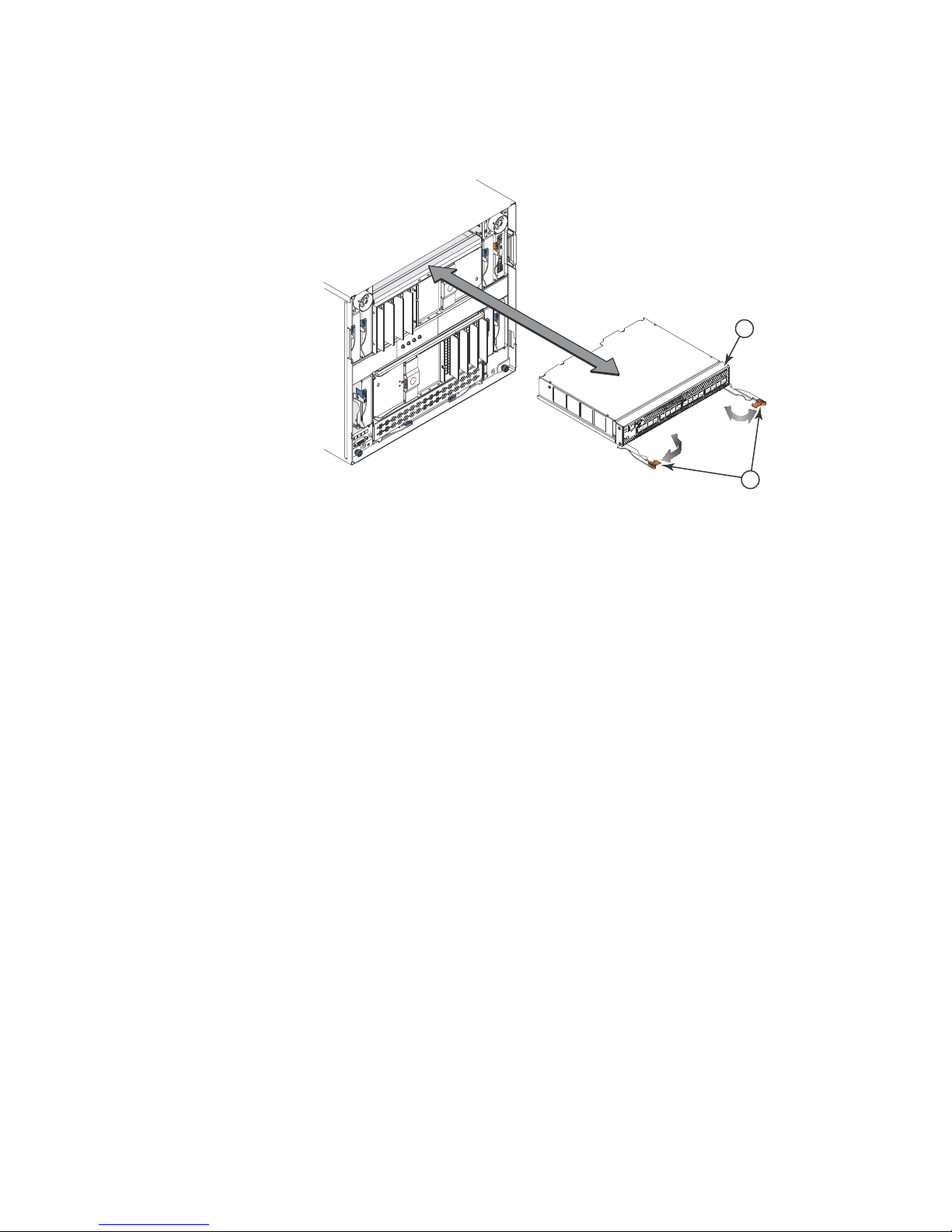
1 Brocade FCoE Switch Module 2 Release levers (open position)
2
1
FIGURE 4 High speed switch module insertion
1. Read the safety information that begins on page ix and “Installation guidelines” on page 9.
2. Select the high-speed module bay in which to install the switch module.
Note: For details about high-speed module bay requirements and bay locations, see the
documentation for the BladeCenter unit and blade servers.
3. Remove the filler module from the selected bay. Store the filler module for future use. The high
speed switch module is a double-height unit and will take up two HSSM bays. If you have two
single height filler modules, remove both from the adjacent bays.
4. If you have not already done so, touch the static-protective package that contains the switch
module to an unpainted metal surface of the BladeCenter unit or an unpainted metal surface
on any other grounded rack-component for at least 2 seconds.
5. If you are installing the switch module in a BCH-T chassis, you must first install the upper and
lower interposer trays and the gasket kit. Please see the instructions shipped with the
Interposer Kit for details. Other wise, skip to step 6.
6. Remove the switch module from its static-protective package.
7. Make sure that the release levers on the switch module are in the open position (perpendicular
to the module).
For specific instructions for installing a switch module in the BladeCenter unit, see the
documentation that comes with the BladeCenter unit.
8. Slide the switch module into the applicable high-speed module bay until it stops.
9. Push the release levers on the front of the switch module to the closed position. After you
insert and lock the switch module, it is turned on, and a power-on self-test (POST) occurs to
verify that the switch module is operating correctly.
Notes:
Chapter 2. Installing and replacing a high speed switch module 11
Page 26

The switch module takes approximately 60 seconds to complete the POST. When the
switch module is turned on, an LED test occurs. All LEDs are lit and remain lit during POST;
then, all the LEDs except the OK LED turn off. This indicates normal POST results.
To maintain proper airflow, make sure that the ventilation holes on the front of the switch
module are not blocked.
10. Make sure that the LEDs on the switch module indicate that it is operating correctly (see
“Information LEDs” on page 24).
11. If you have another switch module to install, repeat step 3 on page 10 through step 10;
otherwise, go to the next step.
12. Install any additional SFP+ modules you may have ordered in the switch module. For
information and instructions, see , “Chapter 3. Installing and removing an SFP+ module” on
page 15 and the documentation that comes with the SFP+ module.
13. Attach any cables that are required by the switch module. For additional information about
cabling the switch module, see , “Chapter 4. Cabling the switch module and the SFP+ module”
on page 19, the documentation that comes with the cables, and the optional network devices
to which the cables have been connected. For the locations of the connectors on the
BladeCenter unit, see the documentation that comes with the BladeCenter unit. Then,
continue with the next step.
14. Make sure that the external ports on the switch module are enabled through one of the
management module interfaces, such as the Web-based interface or the CLI.
Removing or replacing a switch module
Note: The following illustration shows how to remove and replace a switch module from a Type
8852 BladeCenter unit. The appearance of your BladeCenter unit might be different; see the
documentation for your BladeCenter unit for additional information.
To replace a switch module, complete the following steps:
12 Brocade FCoE Switch Module for IBM BladeCenter: Installation and User Guide
Page 27

1 Brocade FCoE Switch Module 2 Release levers (open position)
2
1
FIGURE 5 High speed switch module removal
1. Read the safety information that begins on page ix, and “Installation guidelines” on page 9.
2. Disconnect any cables from the switch module that you are removing. Removing these cables
(especially an Ethernet cable) disrupts the network connection from the external Ethernet port
to any connected external Ethernet devices. If you plan to replace the switch module with
another switch module, you can use the existing Ethernet cable, provided that it remains
securely attached to the Ethernet network. For additional information about cabling the switch
module, see “Chapter 4. Cabling the switch module and the SFP+ module” on page 19, the
documentation that comes with the cables, and the optional network devices to which the
cables have been connected. For the locations of the connectors on the BladeCenter unit, see
the documentation that comes with the BladeCenter unit. Then, continue with step 3.
3. Pull the release latches out from the switch module. The switch module moves out of the bay
approximately 0.6 cm (0.25 inch).
4. Slide the switch module out of the bay and set it aside.
5. Place either another switch module or a filler module in the bay.
Important: Complete this step within 1 minute. (For more information, see steps 8 and 9 on
page 11.)
6. If you placed a switch module in the bay, reconnect the other cables that you disconnected.
Attach any additional cables that are required by the switch module. For additional information
about cabling the switch module, see “Chapter 4. Cabling the switch module and the SFP+
module” on page 19, the documentation that comes with the cables, and the optional network
devices to which the cables have been connected. For the locations of the connectors on the
BladeCenter unit, see the documentation that comes with the BladeCenter unit. Then,
continue with “Chapter 3. Installing and removing an SFP+ module” on page 15.
Chapter 2. Installing and replacing a high speed switch module 13
Page 28

14 Brocade FCoE Switch Module for IBM BladeCenter: Installation and User Guide
Page 29

Chapter 3. Installing and removing an SFP+ module
NOTE
CAUTION
DANGER
The switch module supports both the 8-Gbps and 4-Gbps FC SFP+ transceiver and the 10-Gbps
CEE SFP+ transceiver. The SFP+ transceivers are laser products that convert electrical signals to
optical signals.
For additional information about the location of the switch module, the network interface
requirements, and expansion options, see the documentation for your BladeCenter unit.
The illustrations in this document might differ slightly from your hardware.
Handling an SFP+ module
Before you install an SFP+ module, read the following information:
• The module housing of the SFP+ has an integral guide key that is designed to prevent you from
inserting the module incorrectly.
• Use minimal pressure when you insert the module into the port. Forcing the module into the
port can cause damage to the module or the module port.
• You can insert or remove the module while the BladeCenter unit is turned on.
• You must first insert the module into the port before you can connect the cables.
• You must remove the cable from the SFP+ module before you remove the SFP+ module from
the switch module.
Statement 3:
When laser products (such as CD-ROMs, DVD drives, fiber optic devices, or transmitters) are
installed, note the following:
• Do not remove the covers. Removing the covers of the laser product could result in
exposure to hazardous laser radiation. There are no serviceable parts inside the device.
• Use of controls or adjustments or performance of procedures other than those specified
herein might result in hazardous radiation exposure.
Some laser products contain an embedded Class 3A or Class 3B laser diode.
Note the following:
Laser radiation when open. Do not stare into the beam, do not view directly with optical
instruments, and avoid direct exposure to the beam.
© Copyright IBM Corp. 2010 15
Page 30

CAUTION
Class 1 Laser Product
ATTENTION
Laser Klasse 1
Laser Klass 1
Luokan 1 Laserlaite
Appareil A` Laser de Classe 1
Installing an SFP+ module
The SFP+ module provides two fiber-optic cable connectors for connecting to external ports. To
install an SFP+ module, complete the following steps:
1. Read the safety information that begins on page ix and “Installation guidelines” on page 9.
2. If you have not already done so, touch the static-protective package that contains the SFP+
module to an unpainted metal surface of the BladeCenter chassis or an unpainted metal
surface on any other grounded rack component in the rack in which you are installing the
switch module for at least 2 seconds.
3. Read the information in “Handling an SFP+ module” on page 15.
4. Remove the SFP+ module from its static-protective package.
5. Remove the protective insert, if one is installed, from the port where you are installing the
SFP+ module and store it in a safe place.
6. Remove the protective cap from the SFP+ module and store it in a safe place.
To avoid damage to the cable or the SFP+ module, make sure that you do not connect the fiber
optic cable before you install the SFP+ module.
7. Insert the SFP+ module into the SFP+ module port until it clicks into place.
16 Brocade FCoE Switch Module for IBM BladeCenter: Installation and User Guide
Page 31

ATTENTION
1FC ports 3Protective cap
4
3
2
1
2 FCoE/CEE ports 4 SFP+ module
FIGURE 6 SFP+ installation
8. Remove the protective cap from the transceiver and connect the fiber optic cable (see
“Connecting the SFP+ module cable” on page 20) and any cables that you disconnected
earlier.
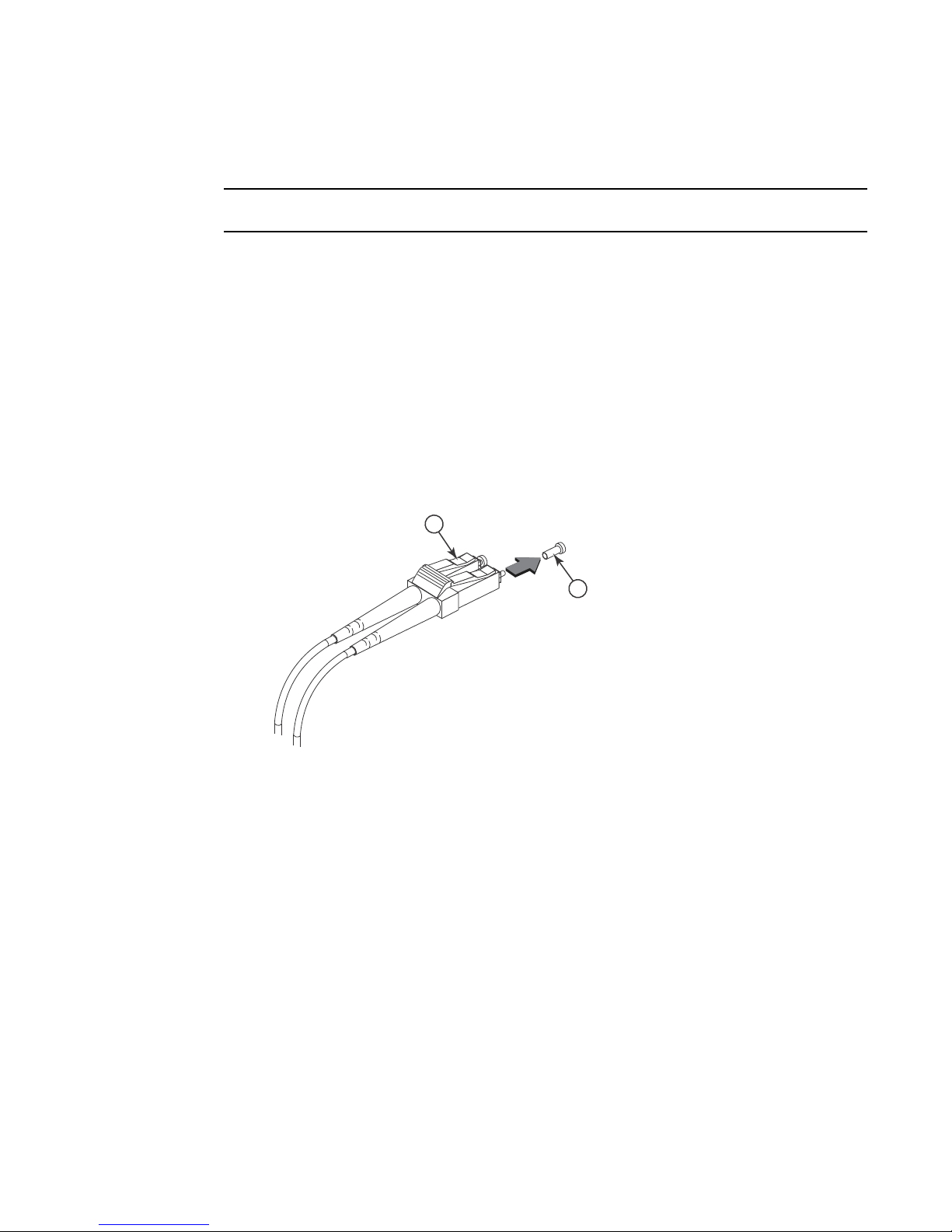
Removing an SFP+ module
To remove an SFP+ module, complete the following steps:
1. Read the safety information that begins on page v and “Installation guidelines” on page 9.
2. Read the information in “Handling an SFP+ module” on page 15.
3. Remove the fiber optic cable from the SFP+ module that you want to replace. For more
information about removing the cable, see “Disconnecting the SFP+ module cable” on
page 21.
To avoid damage to the cable or the SFP+ module, make sure that you disconnect the
fiber-optic cable before you remove the SFP+ module.
4. Unlock the SFP+ module by pulling the wire tab straight out, as shown in the following
illustration.
Chapter 3. Installing and removing an SFP+ module 17
Page 32

1 Protective cap 3 SFP+ module
3
2
1
2Wire tab
FIGURE 7 SFP+ removal
5. Grasp the wire tab on the SFP+ module and pull it out of the port.
6. Replace the protective cap on the SFP+ module and the port.
7. Place the SFP+ module into a static-protective package.
18 Brocade FCoE Switch Module for IBM BladeCenter: Installation and User Guide
Page 33
Chapter 4. Cabling the switch module and the SFP+ module
NOTE
2
1
This chapter describes how to cable the switch module and its optional devices.
The illustrations in this document might differ slightly from your hardware.
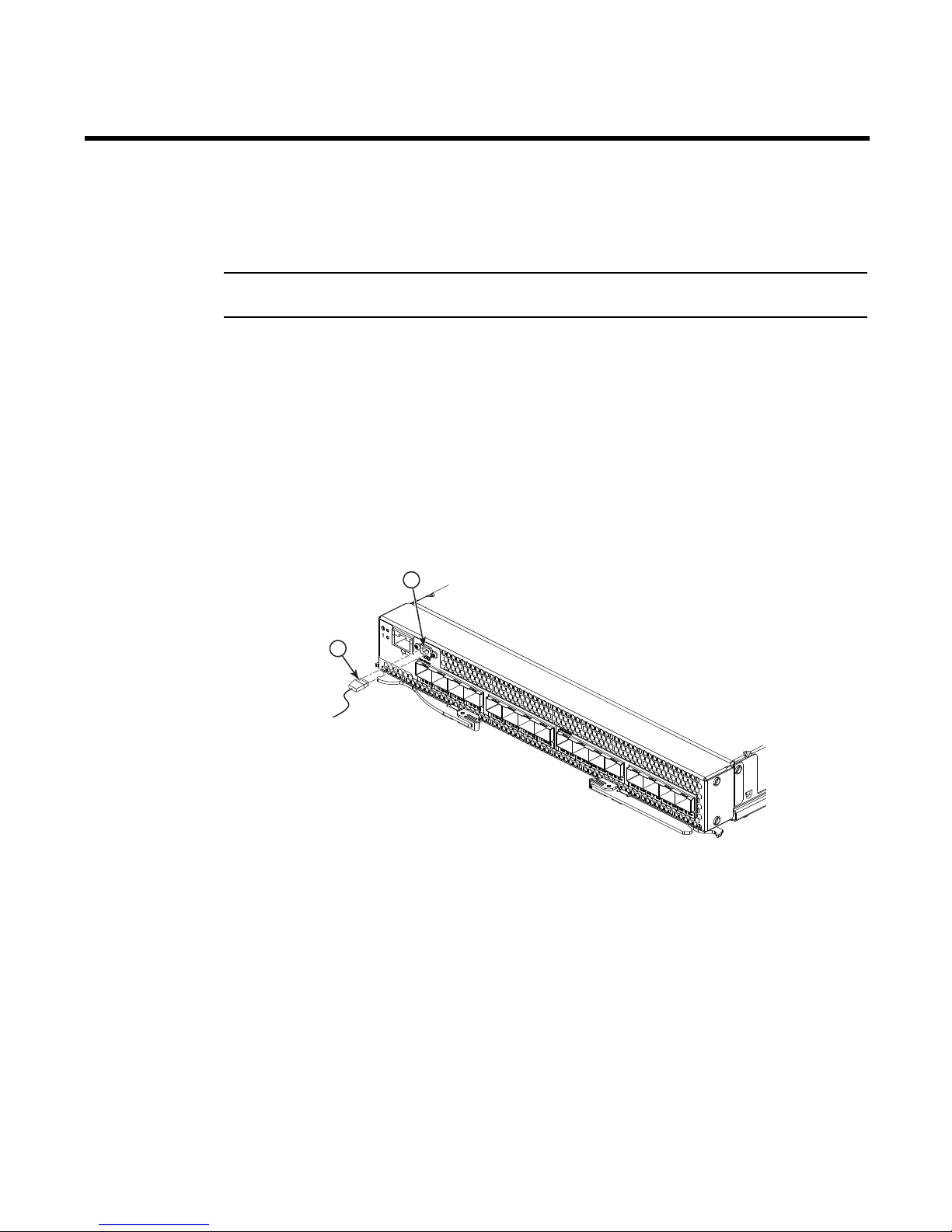
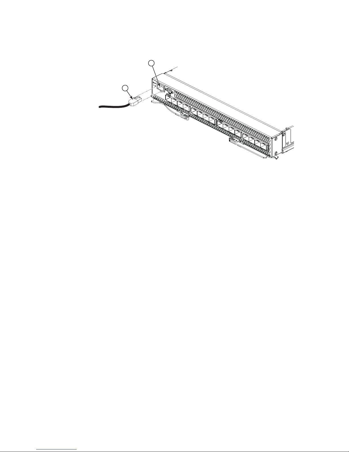
Connecting the USB console cable
To connect the USB console cable to the switch module, connect the cable to the mini-USB console
port of the switch module and the other end of the cable to the console device.
The USB console cable supplied with the Brocade FCoE Switch Module has a mini-USB connector
for the switch module connection and a DB9 male connector to connect to your console device.
Depending on your requirements to connect with the console device, you may need to use a DB9 to
RJ45 adapter also supplied with the switch module. Both straight and crossover adapters are
supplied. Additional cabling and adapters may also be required.
1 USB console cable 2 mini-USB console port
FIGURE 8 USB cable connection
Disconnecting the USB console cable
To disconnect the USB console cable, grasp the connector and gently pull the cable from the switch
module.
© Copyright IBM Corp. 2010 19
Page 34
Connecting the SFP+ module cable
ATTENTION
To avoid damage to the fiber optic cables, follow these guidelines:
• Do not route the cable along a folding cable-management arm.
• When you attach the cable to a device on slide rails, leave enough slack in the cable so that it
does not bend to a radius of less than 38 mm (1.5 in.) when the device is extended or become
pinched when the device is retracted.
• Route the cable away from places where it can be snagged by other devices in the rack.
• Do not overtighten the cable straps or bend the cables to a radius of less than 38 mm (1.5 in.).
• Do not put excess weight on the cable at the connection point. Make sure that the cable is well
supported.
To connect the SFP+ module cable, complete the following steps:
1. Remove the protective caps from the end of the fiber optic cable.
1
2
1 Fiber optic cable 2 Protective cap
FIGURE 9 Fiber optic cable cap
2. Gently slide the fiber optic cable into the SFP+ module until it clicks into place.
20 Brocade FCoE Switch Module for IBM BladeCenter: Installation and User Guide
Page 35

1 FC ports 3 Fiber optic cable
2
1
3
4
2 CEE ports 4 SFP+ module
FIGURE 10 Fiber optic cable insertion
3. Check the LEDs on the switch module. When the switch module is operating correctly, the
green link LED is lit. For information about the status of the switch module LEDs, see ,
“Chapter 5. Information panels, LEDs, and external ports,” on page 23.
Disconnecting the SFP+ module cable
To disconnect the SFP+ module cable, complete the following steps:
1. Squeeze the release tabs and gently pull the fiber optic cable from the SFP+ module.
2. Replace the protective caps on the ends of the fiber optic cable.
Connecting the RJ-45 Ethernet cable
The RJ-45 Ethernet cable can be connected to the RJ-45 port.
To connect the RJ-45 connector to the switch module, push the connector into the port connector
until it clicks into place, as shown in the following illustration.
Chapter 4. Cabling the switch module and the SFP+ module 21
Page 36
1 RJ-45 cable 2 RJ-45 Ethernet port
2
1
FIGURE 11 RJ-45 cable connection
Disconnecting the RJ-45 cable
To disconnect the RJ-45 connector, squeeze the release tab and gently pull the cable connector out
of the switch module connector.
22 Brocade FCoE Switch Module for IBM BladeCenter: Installation and User Guide
Page 37
Chapter 5. Information panels, LEDs, and external ports
NOTE
4
3
3
5 6
12
11
13
1310
10
9
8
10
7
2
1
This chapter describes the information panels and LEDs on the switch module and identifies the
external ports on the information panels.
The illustrations in this document might differ slightly from your hardware
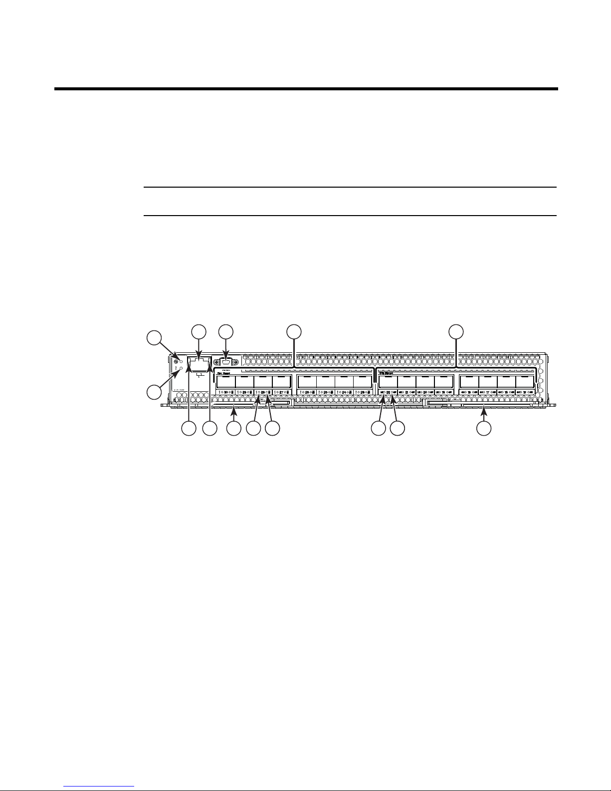
Information panel
The front panel of the switch module contains information LEDs, eight FC and eight CEE SFP+
module port connectors, one mini-USB console port connector, and one Ethernet port connector,
as shown in the following illustration.
1 Status/Fault LED (amber) 8 CEE port link status LED (green)
2 Power LED (green) 9 FC port fault status LED (amber)
3 Ethernet port (RJ45) 10 FC port Tx/Rx link status LED (green)
4 Console port (mini-USB) 11 Ethernet port speed LED (green)
5 Fibre Channel ports (23-30 - right to left) 12 Ethernet port Link LED (green)
6 CEE ports (15-22 - right to left) 13 Release levers(2)
7 CEE port fault status LED (amber)
FIGURE 12 high speed switch module front panel
The switch module information panel contains the following components:
• LEDs that display the following information:
- The status of the switch module and its network connection
- The status of the external connections to the switch module
For further details about LEDs, see “Information LEDs” on page 24.
• Eight FC SFP+ port connectors to attach SFP+ modules. They are numbered 23-30 right to left.
• Eight FCoE/CEE SFP+ port connectors to attach SFP+ modules. They are numbered 15-22
right to left
© Copyright IBM Corp. 2010 23
Page 38

• One RJ-45 Ethernet port connector. Do not attach any devices to this connector other than a
NOTE
NOTE
compatible cable.
• One mini-USB console port connector used for switch management. This port requires a
mini-USB plug on the serial cable.
Information LEDs
The front panel of the switch module has two sets of LEDs. The power and status/fault LEDs on the
left of the switch module indicate the switch module status. The fault (!) and activity (TX/RX) LEDs
on the FC ports and the fault (!) and activity (TX/RX) LEDs on the CEE ports indicate the status of
the external ports. Each port has two LEDs. The Ethernet port has separate link and activity LEDs.
See Figure 12 on page 23 for the locations of the LEDs on the switch module. These LEDs are
described in “Switch module status LEDs” on page 24 and “Port status LEDs” on page 25.
An amber LED on the BladeCenter unit is lit when a system error or event has occurred. To identify
the error or event, check the BladeCenter Advanced Management Module event log or the switch
system log.
An LED test occurs whenever the switch module is turned on. All LEDs are lit and remain lit during
POST, and then all the LEDs except the OK LED turn off.
Any errors that are detected during POST are written to the system log.
When POST errors are written to the system log, these errors are also written to the BladeCenter
management module event log. If a hardware error, such as a current fault occurs, the
management module displays it. If a software error occurs, the management module displays the
Module did not complete POST message and a post error code that indicates the test that was
running when the error was detected.
You can also use the management module to make sure that the switch module is operating
correctly. For more information, see the documentation for the BladeCenter unit.
Switch module status LEDs
The following table provides descriptions of the switch module status LEDs on the front panel of the
switch module.
24 Brocade FCoE Switch Module for IBM BladeCenter: Installation and User Guide
Page 39

TABLE 2 Switch module status LEDs
Status LED Description
Status/fault (!) LED (amber) • Steady amber. There has been a POST failure or critical alert.
Note: When this LED is lit, the system-error LED on the
BladeCenter unit is also lit.
• Off. The switch module is working correctly if the green power
LED is on. If the green LED is also off, the switch module is off.
Power ( ) LED (green)
• Steady green. The switch module is on.
• Off. When the amber switch module error LED is on, it indicates
a critical alert. When the amber LED is also off, it indicates that
the switch module is off.
Port status LEDs
The following table provides descriptions of the port status LEDs on the front panel of the switch
module.
TABLE 3 Port status LEDs
Status LED Description
FC Tx/Rx Status LED (green) • No light. There is no link.
• Steady green. There is a link.
• Flashing green.There is link activity.
FC Fault Status LED (amber)
CEE Link Status LED (green)
CEE Fault Status LED (amber)
Ethernet Link LED (green)
Ethernet Speed LED (green)
• Steady amber. There is a fault on the port.
• No light. There is no link.
• Steady green. There is a link.
• Flashing green.There is link activity.
• Steady amber. There is a fault on the port.
• No light. There is no link.
• Steady green. There is a link.
• Blinking green. There is link activity.
• No light. Port speed is 10 Mbps.
• Steady green. Port speed is 100/1000 Mbps.
POST activity
Once installed, the high speed switch module is managed by the blade server chassis
Management Module. For specific information about managing the high speed switch module,
refer to the blade server chassis manufacturer’s documentation.
The Power-on Self Test (POST) system check is performed each time the switch module is powered
on, rebooted, or reset. During the POST, the LEDs are activated in various indicator patterns.
To determine whether POST completed successfully, or whether any errors were detected:
• Verify that the LEDs on the switch module indicate a healthy high speed switch module.
Chapter 5. Information panels, LEDs, and external ports 25
Page 40

If one or more LEDs do not display a healthy state, verify that the LEDs are not set to beacon.
Use the switchShow command or Web Tools to verify the LED state. For information about how
to turn beaconing on and off, refer to the Fabric OS Administrator’s Guide or the Web Tools
Administrator’s Guide.
• Use the blade server chassis’ Management Module to verify that the switch module is working
correctly.
• Review the system log for errors.
Any errors detected during POST are written to the system log. This log is accessible through
the errShow command. For information about this command, refer to the Fabric OS Command
Reference. For information about error messages, refer to the Fabric OS Message Reference.
POST-operation LED indications
The system status LEDs flash in various patterns during boot, POST, or other diagnostic tests. This
is normal and does not indicate a problem unless the LEDs do not indicate a healthy state after all
boot processes and diagnostic tests are complete.
During POST and some diagnostics, both system status LEDs—located at the top of the installed
switch module—operate simultaneously. The LED indications are described in
TABLE 4 LED Patterns, POST mode
Condition Power LED
(Green)
Status/Fault LED
(Amber)
Tab le 4.
pre-POST start Off Off
POST start
Lamp test
POST in progress
POST critical failure
(nonfunctional)
POST noncritical failure
(functioning but degraded mode)
POST successful complete On Off
Extended POST start Blinking Off
Extended POST critical failure
(nonfunctional)
Extended POST noncritical failure
(functioning but degraded mode)
On briefly
Blinking
Off On
On On
Off On
On On
On briefly
Off
26 Brocade FCoE Switch Module for IBM BladeCenter: Installation and User Guide
Page 41

Chapter 6. Configuring the switch module
The switch module has an internal Ethernet path to the management module, eight external CEE
ports, eight external FC ports, one external management port, and a serial console port. The switch
module supports two remote-access modes for management through Ethernet connections. You
can select the mode that is best suited for your BladeCenter environment.
• Default mode: The default mode uses the internal path to the management module only. In
this mode, the remote-access link to the management console must be attached to the
Ethernet connector on the management module. The Internet protocol (IP) addresses and
SNMP parameters of the switch modules can be automatically assigned by the IBM Director
BladeCenter Deployment wizard (when available), or you must assign them through the
BladeCenter Management and Configuration Program. This mode enables you to provide a
secure LAN for management of the BladeCenter subsystems that is separate from the data
network. See “Establishing a TCP/IP session through the management module” on page 28 for
more information.
• Remote management mode: You can enable remote management of the switch module
through the external ports, instead of or in addition to access through the management
module. This mode can be enabled only through the management module configuration
interface. When this mode is enabled, the external SFP+ ports support both management
traffic and BladeCenter application data traffic. This mode enables the use of additional switch
module IP addresses on different IP subnets than the management modules. This is useful
when the switch modules are to be managed and controlled as part of the overall network
infrastructure, while secure management of other BladeCenter subsystems is maintained
through the management module. See “Enabling management through external ports” on
page 29 for additional instructions about configuring the switch module for this mode of
operation.
The mini-USB console port provides an alternative path to manage and configure the switch for
local access.
Important:
• Before you configure the switch module, make sure that the management modules in the
BladeCenter unit are correctly configured. For more information about configuring the switch
module, see the following documents:
- Installation and User’s Guide for the BladeCenter unit
- BladeCenter Advanced Management Module Installation Guide or BladeCenter T
Advanced Management Module Installation Guide
- IBM BladeCenter Advanced Management Module User’s Guide
• When installed in high-speed slots 7/8, the default IP address of the switch module is
10.90.90.80. When installed in high-speed slots 9/10, the default IP address of the switch
module is 10.90.90.81.
• If you change the IP address of the switch module from the AMM. and restart the switch, it will
maintain this new IP address as its default value.
• The management module and the switch module can communicate with each other only if they
are on the same IP subnet.
© Copyright IBM Corp. 2010 27
Page 42

• When you use the management module Web interface to update the switch module
NOTE
configuration, the management module firmware saves the new configuration in its internal
nonvolatile random access memory (NVRAM). If the switch module restarts, the management
module applies the saved configuration to the switch module.
If the switch module restarts and the management module cannot apply the saved
configuration, the switch module defaults to using the configuration that it had previously
saved. If the IP subnet address of the switch module does not match the IP subnet address of
the management module, you can no longer manage the switch module from the management
module.
• For switch communication with a remote management station, such as an IBM Director
management server, through the management module external Ethernet port, the switch
module internal-network interface and the management module external interface must be on
the same IP subnet.
• Only one FCoE-capable VLAN can be configured on the Brocade FCoE Switch Module.
For specific details about configuring the switch module and preparing for system installation, see
the documentation listed in “Related documentation” on page 3.
Notes:
• Unless otherwise stated, references to the management module apply only to the BladeCenter
Advanced Management Module, which is the only type of management module that supports
the switch module.
• Throughout this document, the management module Web-based user interface is also known
as the BladeCenter management module Web interface.
• Throughout this document, the user name is also known as the login name or user ID for
logging on to interfaces or programs.
• The screens that are described or referenced in this document might differ slightly from the
screens that are displayed by your system. Screen content varies according to the type of
BladeCenter unit and the firmware versions and options that are installed
Establishing a TCP/IP session through the management module
To establish a TCP/IP session for the switch module through the management module, complete
the following steps:
1. Log on to the management module as described in the User’s Guide or Command Line
Interface Reference Guide for your advanced management module. If necessary, obtain the IP
address of the management module from your system administrator. The management
module window opens.
The User ID and Password fields are case-sensitive. Type your information in uppercase letters
only. To maintain system security, change your password after you log on for the first time. The
default User ID is USERID, and the default password is PASSW0RD (where the sixth character
is the number zero, not the letter O).
2. From the I/O Module Tasks menu, click Configuration.
3. In the I/O Module Configuration area, click the bay number that corresponds to the location of
the switch module that you installed.
28 Brocade FCoE Switch Module for IBM BladeCenter: Installation and User Guide
Page 43

4. In the IP address field in the New Static IP Configuration area, type the new TCP/IP address of
NOTE
the switch module; then, click Save.
The management module does not check for invalid IP addresses.
5. Click Advanced Configuration. You can now start a Web session or a Telnet session.
The Web interface and the Telnet program provide different ways to access the same
internal-switching software and configure it.
• If your system application requires that you use the Web interface program, see “Configuring
the switch module through the switch module browser-based interface” on page 32 for
additional information.
• If your system application requires that you use the Telnet program, see “Configuring the
switch module through the Telnet interface” on page 30 for additional information.
Enabling management through external ports
To access and manage the switch module through external interfaces, you must enable the
external ports and the ability to manage the switch through them. Use the information in the
following table to configure your ports.
TABLE 5 LED Patterns, POST mode
External Management External ports Description
Disabled Disabled The switch must be
managed
management module. No
traffic is allowed on
external ports.
Disabled Enabled The switch must be
managed
management module.
Data traffic is allowed on
external ports
Enabled Disabled This mode is not
supported.
Enabled Enabled
The switch can be
managed
management module, a
blade server, or a
management station that
is connected through an
external port. Data traffic
is allowed on
ports.
through the
through the
through the
external
To enable management through external ports, complete the following steps:
Chapter 6. Configuring the switch module 29
Page 44

1. Log on to the management module as described in the User’s Guide or Command Line
Interface Reference Guide for your advanced management module.
If necessary, obtain the IP address of the management module from your system
administrator. The management module window opens.
2. Click I/O Module Tasks → Configuration and click the bay number that corresponds to the
location of the switch module that you installed.
3. Click Advanced Configuration and make sure that external management is enabled.
4. Click I/O Module Tasks → Admin/Power/Restart and make sure that the external ports are
enabled for the switch module that you installed.
Configuring the switch module through the Telnet interface
The switch module supports a command-line interface (CLI) that you can use to configure and
control the switch module over the network through the Telnet program. You can use the CLI to
perform many basic network-management functions. In addition, you can configure the switch
module for management through an SNMP-based network-management system. The following
sections describe how to use the Telnet interface to access the switch module, change its settings,
and monitor its operation.
Connecting to the switch module
If you know the IP address for the switch module and you have an existing network connection, you
can use the Telnet program from an external management station or the management module to
access and control the switch module. The management station and the switch module must be on
the same IP subnet. If you have to obtain the IP address for the switch module or establish a
network connection, contact your system or network administrator. Be sure to use the correct IP
address in the required command, as specified in
“Accessing the main menu.”
Accessing the main menu
To connect to the switch module through the Telnet interface, complete the following steps:
1. From a DOS command-line prompt, type telnet xxx.xxx.xxx.xxx and press Enter.
where xxx.xxx.xxx.xxx is the IP address for the switch module.
2. The default user ID is USERID and the default password is PASSW0RD, where the sixth
character is a zero.
Important: The apply command changes the currently active configuration. If you want your change
to persist beyond the next reboot of the switch, you must enter the save command. This command
stores the current switch configuration and all changes in nonvolatile memory.
30 Brocade FCoE Switch Module for IBM BladeCenter: Installation and User Guide
Page 45

Configuring the switch module through the mini-USB interface
2
1
The mini-USB port provides basic communication serial-data transfer through a terminal emulation
program (such as Hyperterminal). Because messages from the power-on self-test (POST) and all
initialization information are transmitted through the serial port, you can use the serial port to log in
to the switch module and access and configure the internal switching software.
To log in to the switch module, complete the following steps:
1. Connect one end of the specifically designed USB cable that comes with your device into the
mini-USB port and connect the other end to the management station.
1 USB console cable 2 mini-USB console port
FIGURE 13 USB cable connection
For additional information, see “Connecting the USB console cable” on page 19.
2. On the management station, open a console window and make sure that the serial port is
configured with the following settings:
9600 baud
8 data bits
No parity
1 stop bit
No flow control
3. Type the user name and password. The default user name is USERID. The default password is
PASSW0RD where the sixth character is a zero.
The mini-USB port is compatible with the standard 16550 Universal Asynchronous
Connecting to the switch module using Web Tools
Receiver/Transmitter (UART) protocol. The port is enabled by default.
Perform these steps to connect directly to the switch module using the Brocade Web Tools without
using the management module. Brocade Web Tools is a graphical user interface you can use to
configure the switch directly.
Chapter 6. Configuring the switch module 31
Page 46

1. On a computer in the same network as the switch module, open a supported web browser,
NOTE
such as Internet Explorer.
2. Enter the IP address of the switch module in the address field.
3. Log into Web Tools using the default administrative account.
Login: USERID
Password: PASSW0RD where the sixth character is a zero
See the Web Tools Administrator’s Guide for more information on using Web Tools.
The passwords that are used to access the switch module are case-sensitive. To increase system
security, change the password after you log on for the first time.
Initial configuration
The operating software on the switch module contains default configuration files that are installed
during the software installation. These initial configuration settings are not in a separate
configuration file but are components of the software. When you restore the management module
to factory defaults, the original configuration is restored.
Logging in to the switch module
The switch module supports user-based security that enables you to prevent unauthorized users
from accessing the switch or changing its settings.
To log in to the switch module, complete the following steps:
1. At the prompt, type your user ID and press Enter. The default user ID is USERID.
2. Type your password (default is PASSW0RD where the sixth character is a zero) and press Enter.
The main-menu window opens.
After you log on to the switch module, you must set the date and time by using the date command
in the form date “mmddhhmmyy” where mm is month, dd is day, hh is hour, mm is minute, and yy is
year.
Configuring for FCoE
The initial configuration of the switch has the CEE ports shut down. In order to configure the ports
for FCoE operation, you must access the CEE command shell and configure both the internal and
external CEE ports. Once you have logged into the switch, use the cmsh command to access the
CEE command shell. Use the following steps to configure the CEE ports.
1. Login to the switch.
2. From the command prompt type cmsh and press Enter.
3. Type enable and press Enter.
32 Brocade FCoE Switch Module for IBM BladeCenter: Installation and User Guide
Page 47

4. Type conf t and press Enter.
5. Type int int (press tab to complete the second int) 0/x where x is the internal port you wish to
change and press Enter.
6. Once in the particular interface type fcoeport and press Enter.
7. T yp e no shut and press Enter.
8. Type exit and press Enter.
9. Repeat steps 5-8 for any other blade port you wish to configure.
10. Once finished with all of the blade ports, type exit and press Enter (you should still be in the
CMSH at this point).
11. Type write mem and press Enter.
Answer yes to overwrite the startup file.
12. Type copy run start and press Enter.
Answer yes to overwrite.
See the Converged Enhanced Ethernet Administrator’s Guide for information about CEE CLI
interface and configuring switches for FCoE operation and the Converged Enhanced Ethernet
Command Reference for more details on the commands.
Backing up the configuration
Perform these steps to back up the switch module configuration to an FTP server.
1. Open a Telnet or SSH session to the switch module.
2. Enter configUpload.
You are then presented with a series of prompts.
3. Follow the prompts to upload the configuration.
This command uploads the switch module configuration to the server, making it available for
downloading to a replacement switch module if necessary.
Brocade recommends backing up the configuration on a regular basis to ensure that a complete
configuration is available for downloading to a replacement switch module.
For specific instructions about how to back up the configuration, refer to the Fabric OS
Administrator’s Gui de. The switchShow, fabricShow, and configUpload commands are described in
detail in the Fabric OS Command Reference.
Chapter 6. Configuring the switch module 33
Page 48

Resetting the Brocade FCoE Switch Module to factory defaults
ATTENTION
Restoring the switch module to factory defaults is disruptive. Before beginning, make sure that any
program using the high speed switch module has an alternate path to the storage and save the
switch module configuration. If the high speed switch module is connected to an existing SAN,
disconnect the switch module from the SAN before restoring to factory defaults and then follow
proper setup procedures before reconnecting.
Use the Management Module to reset the high speed switch module to factory defaults.
1. Open the Management Module and log in with admin privileges.
2. Select I/O Module Tasks > Configuration.
3. Select either bay 7 or bay 9 depending on where the switch module is installed.
4. Select Advanced Configuration.
5. Click Restore Defaults.
34 Brocade FCoE Switch Module for IBM BladeCenter: Installation and User Guide
Page 49

Chapter 7. Understanding Access Gateway
NOTE
NOTE
The Brocade FCoE Switch Module can function in either Fabric OS Native mode or Brocade Access
Gateway (AG) mode. Brocade Access Gateway is a Fabric OS feature that lets you configure your
Enterprise fabric to handle additional N_Ports instead of domains. By reducing the number of
domain IDs and ports you simplify configuration and management in a large fabric.
The Brocade FCoE Switch Module cannot be used as a core AG, only as an edge AG. However, there
is no limit as to how many Brocade FCoE Switch Modules can be connected to a core AG.
Switch modules in AG mode are logically transparent to the host and the fabric. You can increase
the number of hosts that have access to the fabric without increasing the number of switch
modules.
The switch is shipped in Fabric OS Native mode by default.
• For a list of available features in Access Gateway mode, refer to the Brocade Access Gateway
Administrator’s Gui de and the Release Notes accompanying the Brocade FCoE Switch Module.
• You can enable AG mode using Fabric OS commands or Web Tools.
• When you enable AG mode, you can use the default F_Port-to-N_Port mappings or change this
mapping using command line interface (CLI) or Web Tools after you configure an IP address.
• AG simplifies SAN deployment by using N_Port ID Virtualization (NPIV). NPIV provides Fibre
Channel switch functions that improve switch scalability, manageability, and interoperability.
For more information on AG, refer to the following:
- For general information and details on using Access Gateway, refer to the Brocade Access
Gateway Administrator’s Guide and the Release Notes accompanying the Brocade FCoE
Switch Module.
- For specific instructions to prepare the edge fabric before connecting it to Access Gateway
(since Access Gateway relies on NPIV technology for its connection to the edge fabric),
refer to the SAN TECH NOTE – Preparing to Install the Brocade Access Gateway).
An Access Gateway cannot be connected directly into an array; it requires a fabric to support
NPIV.
• In Fabric OS Native mode, the switch provides up to eight external Fibre Channel ports. These
universal and self-configuring ports are capable of becoming one of the following port types:
- F_Port (fabric enabled)
- FL_Port (fabric loop enabled)
- E_Port (expansion port)
- M_Port (mirror port)
• In AG mode, the switch also provides up to eight external Fibre Channel ports. However, these
ports are configured as N_Ports, and you cannot reconfigure these as any other port type.
© Copyright IBM Corp. 2010 35
Page 50

Unlike AG in pure FC switches, port mapping in the high speed switch module proceeds from CEE
NOTE
ports to (internal) FCoE ports to FC ports. Since there are 22 CEE ports (both internal and external)
and 22 FCoE ports (as a bridge from the CEE side of the high speed switch module to the FC side,
the port mapping is one-to-one and no user configuration is required. The 22 FCoE ports, however,
must be mapped to the 8 external FC ports. In AG mode the FCoE ports are functionally equivalent
to F_Ports and the FC ports are configured as N_Ports. The default port mapping configuration
assigns three F_Ports to each N_Port. However, in the high speed switch module you are not
restricted to this kind of grouping. You can assign any F_Port to any one of the N_Ports manually
through the CLI.
Disabling and enabling Access Gateway mode
This section provides steps to disable and enable Access Gateway mode using Fabric OS
commands. For more information on using these commands, refer to the “Enabling and disabling
Access Gateway mode” section in the Brocade Access Gateway Administrator’s Guide or the
Brocade Fabric OS Administrator’s Guide.
You can also disable and enable Access Gateway mode using Web Tools. Refer to the See the Web
T ools Administrator’s Guide for more information.
Enabling Access Gateway mode
Note the following when enabling AG mode:
• After you enable AG mode, some fabric information is erased, such as the zone and security
databases.
• Enabling AG mode is disruptive because the switch is disabled and rebooted.
• Ensure that no zoning or Admin Domain (AD) transaction buffers are active. If any transaction
buffer is active, enabling Access Gateway mode will fail with the error, “Failed to clear
Zoning/Admin Domain configuration.”
Use the following steps to enable AG mode using Fabric OS commands. For more information on
enabling AG mode, refer to “Enabling and disabling Access Gateway mode” in the Brocade Access
Gateway Administrator’s Guide.
1. Access the CLI for the high speed switch module.
2. Before disabling a switch to enable Access Gateway mode, save the current configuration file
using the configUpload command in case you might need this configuration again.
3. Enter the switchShow command to verify the switch mode.
• “Access Gateway Mode” displays for switchMode if the switch is in AG mode.
• “Native” displays for switchMode if the switch is in Fabric OS Native mode.
4. Enter switchDisable to disable the switch. AG mode can only be enabled or disabled when the
switch is in a disabled state.
5. Enter ag –modeEnable to enable AG mode.
6. The switch reboots at this point so you must log back in to the switch.
7. E nte r the ag
36 Brocade FCoE Switch Module for IBM BladeCenter: Installation and User Guide
--modeShow command to verify that AG mode is enabled.
Page 51

switch:admin> ag --modeshow
Access Gateway mode is enabled.
Once AG mode has been enabled, complete the AG configuration. See the Brocade Access
Gateway Administrator’s Guide and the Release Notes accompanying the Brocade FCoE Switch
Module for details. You should be aware of some operational restrictions in AG on the high speed
switch module.
• If an N_Port becomes unreliable, its currently active online F_Ports DO NOT failover to another
N_Port. They remain on the unreliable N_Port.
• The Brocade FCoE Switch Module can support only one FCoE VLAN in AG mode.
• QoS is NOT disabled on the N_Ports.
The following features are not supported:
• Virtual fabrics
• Admin domains
• Port-based zoning
• QoS zoning
• Hot code load (HCL)
• FC-SP
Disabling Access Gateway mode
When you disable Access Gateway mode, the switch automatically reboots and comes back online
using the fabric switch configuration. The Access Gateway parameters, such as F_Port-to-N_Port
mapping, failover, and failback are automatically removed. When the switch reboots, it starts in
Fabric OS Native mode. To re-join the switch to the core fabric, refer to the Brocade Access Gatew ay
Administrator’s Guide.
Use the following steps to disable Access Gateway mode using Fabric OS commands. For more
information, refer to the “Enabling and disabling Access Gateway mode” section in the Brocade
Access Gateway Administrator’s Guide.
1. Enter the switchShow command to verify the switch mode.
“Access Gateway Mode” displays when the switch is in Access Gateway mode.
2. Enter switchDisable to disable the switch. Access Gateway mode can only be disabled or
enabled when the switch is in a disabled state.
3. Enter ag --modeDisable to disable Access Gateway mode.
4. The switch reboots at this point so you must log back in to the switch.
5. Enter the ag
switch:admin> ag --modeshow
Access Gateway mode is NOT enabled
--modeShow command to verify that AG mode is disabled.
Chapter 7. Understanding Access Gateway 37
Page 52

38 Brocade FCoE Switch Module for IBM BladeCenter: Installation and User Guide
Page 53

Chapter 8. Updating the firmware
NOTE
This chapter describes how to determine the level of the firmware that is installed on the switch
module, how to obtain the latest level of switch firmware, and how to reset the switch module to
activate the firmware upgrade.
Determining the level of switch module firmware
After you install the switch module in the BladeCenter unit, make sure that the latest firmware is
installed on the switch module. To determine the level of the firmware that is installed, complete
the following steps:
1. Log on to the management module as described in the IBM BladeCenter Advanced
Management Module User’s Guide. If necessary, obtain the IP address of the management
module from your system administrator. The login window opens.
2. From the Monitors menu, click Firmware VPD. The Firmware VPD window opens.
3. In the I/O Module Firmware VPD area, locate the number of the I/O-module-bay that contains
the switch module that you installed; then, note the corresponding level of the firmware for the
switch module displayed under the Revision column.
Obtaining the latest level of switch firmware
The switch module might have features that are not described in the documentation that comes
with the switch, and the documentation might be updated occasionally to include information
about those features or technical updates.
If firmware and documentation updates are available, complete the following steps:
Changes are made periodically to the IBM Web site. The procedure for locating firmware and
documentation might change from what is described in this document.
1. Go to http://www.ibm.com/systems/support/.
2. Under Choose Support Type, click BladeCenter.
3. Under Product Family menu select BladeCenter H Chassis. Leave other fields as default.
4. Scroll down to view the results.
The switch module can contain two operating-system images. You can revert to the previous image
if the current download process fails.
© Copyright IBM Corp. 2010 39
Page 54

Downloading the firmware
NOTE
Once you have found the correct firmware you want to download to the Brocade FCoE Switch
Module, you can use either the CLI or Web Tools to do the download.
The firmware download for the Brocade FCoE Switch Module is not non-disruptive. Be sure that no
traffic is flowing through the switch during the download process.
For specifics on how to perform the firmware download, please see the chapters regarding
firmware maintenance in the Fabric OS Administ rator’s Guide if you are using the CLI to do the
download or the Web Tools Administrator’s Guide if you are using Web Tools.
Resetting and restarting the switch module
To activate the new image or images, you must reset the switch module. To reset the switch
module, complete the following steps:
1. From the I/O Module Tasks menu, click Admin/Power/Restart. The management module
window opens.
2. Select the I/O-module bay on which the firmware update was just installed.
3. Click Power Off Module(s).
4. Select the I/O-module bay on which the firmware update was just installed.
5. Click Power On Module(s). Wait 60 seconds for POST to be completed.
6. Click Monitors, and select Firmware VPD. The Firmware VPD window opens.
7. In the Firmware VPD window, locate the I/O Module Firmware VPD area.
Page down to the number of the I/O-module bay that contains the switch module that you just
installed; then, note the corresponding level of the firmware for the switch module. Confirm that the
firmware build ID and revision reflect the correct firmware release.
40 Brocade FCoE Switch Module for IBM BladeCenter: Installation and User Guide
Page 55

Chapter 9. Parts
Replaceable components are of three types:
• Tier 1 customer replaceable unit (CRU): Replacement of Tier 1 CRUs is your responsibility. If
IBM installs a Tier 1 CRU at your request, you will be charged for the installation.
• Tier 2 customer replaceable unit (CRU): You may install a Tier 2 CRU yourself or request IBM to
install it, at no additional charge, under the type of warranty service that is designated for your
server.
• Field replaceable unit (FRU): FRUs must be installed only by trained service technicians.
For information about the terms of the warranty, see the IBM Warranty and Support Information
document on the IBM Documentation CD.
The replaceable components in the following table are Tier 1 CRUs. If other BladeCenter
components require replacement, see the following documentation that comes with these devices:
• BladeCenter Problem Determination and Service Guide or Hardw are Maintenance Manual and
Troubleshooting Guide
• Installation and User’s Guide or Installation Guide
TABLE 6 Parts listing
Part CRU number (Tier 1)
Brocade FCoE Switch Module for
IBM BladeCenter
• 69Y1909 (Option)
• 69Y1911 (Tier 1 CRU)
© Copyright IBM Corp. 2010 41
Page 56

42 Brocade FCoE Switch Module for IBM BladeCenter: Installation and User Guide
Page 57

Chapter 10. Solving problems
This section provides basic troubleshooting information to help you solve some problems that
might occur while you are setting up the switch module.
If you cannot locate and correct a problem by using the information in this section, see Appendix A,
“Getting help and technical assistance,” on page 43.
Running POST
To ensure that it is fully operational, the switch module processes a series of tests during power-up
or a restart (power-on self-test, or POST). These tests take approximately 1 minute to complete. The
management module reads the test results and displays them for you. During normal operation,
these tests are completed without error, and the green OK LED is lit. However, if the switch module
fails POST, the amber switch module error LED and the system-error LED on the BladeCenter unit
are lit. An event is stored in the event log in the system status panel of the management module.
The specific failure is displayed on the system status I/O module panel of the management
module.
Note: For the locations and descriptions of the switch module LEDs, see , “Chapter 5. Information
panels, LEDs, and external ports” on page 23.
POST errors
There are two types of errors: noncritical and critical. A noncritical error applies to one port, and the
switch module is operational. You can continue to operate the switch module; however, you must
replace it as soon as possible. When critical errors occur, the switch module does not operate. To
view POST results, complete the following steps:
1. Log on to the management module as described in the IBM BladeCenter Advanced
Management Module Command-Line Interface Reference Guide. If necessary, obtain the IP
address of the management module from your system administrator. The login window opens.
2. Turn off the power to the switch module; then, turn it on again.
3. After POST is completed, the management module displays the results. Refresh the window to
view the POST results. If a critical error occurs, replace the switch module. If a noncritical error
occurs, see the switch module error log for additional details.
Tab le 7 describes the basic critical and noncritical failures. This abbreviated list is representative; it
is not an exhaustive list. An error code is associated with each failure. Error codes are displayed on
the Management Module Switch Information window. Be sure to note the applicable error code and
corresponding failure. You might have to provide this information when you call for service. For
details, see
“Appendix A. Getting help and technical assistance” on page 45.
© Copyright IBM Corp. 2010 43
Page 58

TABLE 7 Error listing
Diagnostic indicator
Failing functional area Failure criticality
(in hex)
00 - 7F Base internal functions Critical
80 - 9F Internal interface failures
A0 - AF
B0 - FE
FF Switch module “good” indicator Operation
External interface errors Noncritical
Reserved Noncritical
Noncritical
44 Brocade FCoE Switch Module for IBM BladeCenter: Installation and User Guide
Page 59

Appendix A. Getting help and technical assistance
If you need help, service, or technical assistance or just want more information about IBM
products, you will find a wide variety of sources available from IBM to assist you. This section
contains information about where to go for additional information about IBM and IBM products,
what to do if you experience a problem with your system, and whom to call for service, if it is
necessary.
Before you call
Before you call, make sure that you have taken these steps to try to solve the problem yourself:
• Check all cables to make sure that they are connected.
• Check the power switches to make sure that the system and any optional devices are turned
on.
• Use the troubleshooting information in your system documentation, and use the diagnostic
tools that come with your system. Information about diagnostic tools is in the Problem
Determination and Service Guide on the IBM Documentation CD that comes with your system.
• Go to the IBM support Web site at http://www.ibm.com/systems/support/ to check for
technical information, hints, tips, and new device drivers or to submit a request for information.
You can solve many problems without outside assistance by following the troubleshooting
procedures that IBM provides in the online help or in the documentation that is provided with your
IBM product. The documentation that comes with IBM systems also describes the diagnostic tests
that you can perform. Most systems, operating systems, and programs come with documentation
that contains troubleshooting procedures and explanations of error messages and error codes. If
you suspect a software problem, see the documentation for the operating system or program.
Using the documentation
Information about your IBM system and preinstalled software, if any, or optional device is available
in the documentation that comes with the product. That documentation can include printed
documents, online documents, readme files, and help files. See the troubleshooting information in
your system documentation for instructions for using the diagnostic programs. The troubleshooting
information or the diagnostic programs might tell you that you need additional or updated device
drivers or other software. IBM maintains pages on the World Wide Web where you can get the
latest technical information and download device drivers and updates. To access these pages, go
to http://www.ibm.com/systems/support/ and follow the instructions. Also, some documents are
available through the IBM Publications Center at http://www.ibm.com/shop/publications/order/.
© Copyright IBM Corp. 2010 45
Page 60

Getting help and information from the World Wide Web
On the World Wide Web, the IBM Web site has up-to-date information about IBM systems, optional
devices, services, and support. The address for IBM System x
http://www.ibm.com/systems/x/. The address for IBM BladeCenter information is
http://www.ibm.com/systems/bladecenter/. The address for IBM IntelliStation
http://www.ibm.com/intellistation/.
You can find service information for IBM systems and optional devices at
http://www.ibm.com/systems/support/.
Software service and support
Through IBM Support Line, you can get telephone assistance, for a fee, with usage, configuration,
and software problems with System x and xSeries servers, BladeCenter products, IntelliStation
workstations, and appliances. For information about which products are supported by Support Line
in your country or region, see http://www.ibm.com/services/sl/products/.
For more information about Support Line and other IBM services, see
http://www.ibm.com/services/, or see http://www.ibm.com/planetwide/ for support telephone
numbers. In the U.S. and Canada, call 1-800-IBM-SERV (1-800-426-7378).
Hardware service and support
You can receive hardware service through your IBM reseller or IBM Services. To locate a reseller
authorized by IBM to provide warranty service, go to http://www.ibm.com/partnerworld/ and click
Find a Business Partner on the right side of the page. For IBM support telephone numbers, see
http://www.ibm.com/planetwide/. In the U.S. and Canada, call 1-800-IBM-SERV
(1-800-426-7378).
®
and xSeries® information is
®
information is
In the U.S. and Canada, hardware service and support is available 24 hours a day, 7 days a week.
In the U.K., these services are available Monday through Friday, from 9 a.m. to 6 p.m.
IBM Taiwan product service
IBM Taiwan product service contact information:
IBM Taiwan Corporation
3F, No 7, Song Ren Rd.
Taipei, Taiwan
Telephone: 0800-016-888
46 Brocade FCoE Switch Module for IBM BladeCenter: Installation and User Guide
Page 61

Appendix B. Notices
This information was developed for products and services offered in the U.S.A. IBM may not offer
the products, services, or features discussed in this document in other countries. Consult your local
IBM representative for information on the products and services currently available in your area.
Any reference to an IBM product, program, or service is not intended to state or imply that only that
IBM product, program, or service may be used. Any functionally equivalent product, program, or
service that does not infringe any IBM intellectual property right may be used instead. However, it is
the user’s responsibility to evaluate and verify the operation of any non-IBM product, program, or
service.
IBM may have patents or pending patent applications covering subject matter described in this
document. The furnishing of this document does not give you any license to these patents. You can
send license inquiries, in writing, to:
Trademarks
IBM Director of Licensing
IBM Corporation
North Castle Drive
Armonk, NY 10504-1785
U.S.A.
INTERNATIONAL BUSINESS MACHINES CORPORATION PROVIDES THIS PUBLICATION “AS IS”
WITHOUT WARRANTY OF ANY KIND, EITHER EXPRESS OR IMPLIED, INCLUDING, BUT NOT LIMITED
TO, THE IMPLIED WARRANTIES OF NON-INFRINGEMENT, MERCHANTABILITY OR FITNESS FOR A
PARTICULAR PURPOSE. Some states do not allow disclaimer of express or implied warranties in
certain transactions, therefore, this statement may not apply to you.
This information could include technical inaccuracies or typographical errors. Changes are
periodically made to the information herein; these changes will be incorporated in new editions of
the publication. IBM may make improvements and/or changes in the product(s) and/or the
program(s) described in this publication at any time without notice.
Any references in this information to non-IBM Web sites are provided for convenience only and do
not in any manner serve as an endorsement of those Web sites. The materials at those Web sites
are not part of the materials for this IBM product, and use of those Web sites is at your own risk.
IBM may use or distribute any of the information you supply in any way it believes appropriate
without incurring any obligation to you.
IBM, the IBM logo, and ibm.com are trademarks or registered trademarks of International Business
Machines Corporation in the United States, other countries, or both. If these and other IBM
trademarked terms are marked on their first occurrence in this information with a trademark
symbol (
the time this information was published. Such trademarks may also be registered or common law
trademarks in other countries. A current list of IBM trademarks is available on the Web at
“Copyright and trademark information” at http://www.ibm.com/legal/copytrade.shtml.
Adobe and PostScript are either registered trademarks or trademarks of Adobe Systems
Incorporated in the United States and/or other countries.
© Copyright IBM Corp. 2010 47
® or ™), these symbols indicate U.S. registered or common law trademarks owned by IBM at
Page 62

Cell Broadband Engine is a trademark of Sony Computer Entertainment, Inc., in the United States,
other countries, or both and is used under license therefrom.
Intel, Intel Xeon, Itanium, and Pentium are trademarks or registered trademarks of Intel
Corporation or its subsidiaries in the United States and other countries.
Java and all Java-based trademarks are trademarks of Sun Microsystems, Inc., in the United
States, other countries, or both.
Linux is a registered trademark of Linus Torvalds in the United States, other countries, or both.
Microsoft, Windows, and Windows NT are trademarks of Microsoft Corporation in the United States,
other countries, or both.
UNIX is a registered trademark of The Open Group in the United States and other countries.
Other company, product, or service names may be trademarks or service marks of others.
Important notes
Processor speed indicates the internal clock speed of the microprocessor; other factors also affect
application performance.
CD or DVD drive speed is the variable read rate. Actual speeds vary and are often less than the
possible maximum.
When referring to processor storage, real and virtual storage, or channel volume, KB stands for
1024 bytes, MB stands for 1 048 576 bytes, and GB stands for 1 073 741 824 bytes.
When referring to hard disk drive capacity or communications volume, MB stands for 1 000 000
bytes, and GB stands for 1 000 000 000 bytes. Total user-accessible capacity can vary depending
on operating environments.
Maximum internal hard disk drive capacities assume the replacement of any standard hard disk
drives and population of all hard disk drive bays with the largest currently supported drives that are
available from IBM.
Maximum memory might require replacement of the standard memory with an optional memory
module.
IBM makes no representation or warranties regarding non-IBM products and services that are
ServerProven
a particular purpose. These products are offered and warranted solely by third parties.
IBM makes no representations or warranties with respect to non-IBM products. Support (if any) for
the non-IBM products is provided by the third party, not IBM.
Some software might differ from its retail version (if available) and might not include user manuals
or all program functionality.
®, including but not limited to the implied warranties of merchantability and fitness for
48 Brocade FCoE Switch Module for IBM BladeCenter: Installation and User Guide
Page 63

Electronic emission notices
Federal Communications Commission (FCC) statement
Note: This equipment has been tested and found to comply with the limits for a Class A digital
device, pursuant to Part 15 of the FCC Rules. These limits are designed to provide reasonable
protection against harmful interference when the equipment is operated in a commercial
environment. This equipment generates, uses, and can radiate radio frequency energy and, if
not installed and used in accordance with the instruction manual, may cause harmful
interference to radio communications. Operation of this equipment in a residential area is
likely to cause harmful interference, in which case the user will be required to correct the
interference at his own expense.
Properly shielded and grounded cables and connectors must be used in order to meet FCC
emission limits. IBM is not responsible for any radio or television interference caused by using
other than recommended cables and connectors or by unauthorized changes or modifications
to this equipment. Unauthorized changes or modifications could void the user’s authority to
operate the equipment.
This device complies with Part 15 of the FCC Rules. Operation is subject to the following two
conditions: (1) this device may not cause harmful interference, and (2) this device must accept
any interference received, including interference that may cause undesired operation.
Industry Canada Class A emission compliance statement
This Class A digital apparatus complies with Canadian ICES-003.
Avis de conformité à la réglementation d’Industrie Canada
Cet appareil numérique de la classe A est conforme à la norme NMB-003 du Canada.
Australia and New Zealand Class A statement
Attention: This is a Class A product. In a domestic environment this product may cause radio
interference in which case the user may be required to take adequate measures.
CE statement
This is a Class A product. In a domestic environment, this product might cause radio interference,
and the user might be required to take corrective measures.
The standards compliance label on the product contains the CE mark which indicates that this
system conforms to the provisions of the following European Council directives, laws, and
standards:
• EN55022:2006 + A1:2007 (European Emissions Requirements)
• EN55024:1998, +A1:2001 and +A2:2003 (European Immunity Requirements)
Appendix B. Notices 49
Page 64

United Kingdom telecommunications safety requirement
Notice to Customers
This apparatus is approved under approval number NS/G/1234/J/100003 for indirect
connection to public telecommunication systems in the United Kingdom.
European Union EMC Directive conformance statement
This product is in conformity with the protection requirements of EU Council Directive
2004/108/EC on the approximation of the laws of the Member States relating to
electromagnetic compatibility. IBM cannot accept responsibility for any failure to satisfy the
protection requirements resulting from a nonrecommended modification of the product,
including the fitting of non-IBM option cards.
Attention: This is an EN 55022 Class A product. In a domestic environment this product may
cause radio interference in which case the user may be required to take adequate measures.
Responsible manufacturer:
International Business Machines Corp.
New Orchard Rd.
Armonk, NY, 10504
914-499-1900
European Community contact:
IBM Technical Regulations, Department 456
IBM-Allee 1, 71137 Ehningen, Germany
Telephone: +49 7032 15-2937
E-mail: tjahn@de.ibm.com
Germany Electromagnetic Compatibility Directive
Deutschsprachiger EU Hinweis:
Hinweis für Geräte der Klasse A EU-Richtlinie zur Elektromagnetischen Verträglichkeit
Dieses Produkt entspricht den Schutzanforderungen der EU-Richtlinie 2004/108/EG zur
Angleichung der Rechtsvorschriften über die elektromagnetische Verträglichkeit in den
EU-Mitgliedsstaaten und hält die Grenzwerte der EN 55022 Klasse A ein.
Um dieses sicherzustellen, sind die Geräte wie in den Handbüchern beschrieben zu
installieren und zu betreiben. Des Weiteren dürfen auch nur von der IBM empfohlene Kabel
angeschlossen werden. IBM übernimmt keine Verantwortung für die Einhaltung der
Schutzanforderungen, wenn das Produkt ohne Zustimmung der IBM verändert bzw. wenn
Erweiterungskomponenten von Fremdherstellern ohne Empfehlung der IBM
gesteckt/eingebaut werden.
EN 55022 Klasse A Geräte müssen mit folgendem Warnhinweis versehen werden: “Warnung:
Dieses ist eine Einrichtung der Klasse A. Diese Einrichtung kann im Wohnbereich
Funk-Störungen verursachen; in diesem Fall kann vom Betreiber verlangt werden,
angemessene Maßnahmen zu ergreifen und dafür aufzukommen.”
Deutschland: Einhaltung des Gesetzes über die elektromagnetische
Verträglichkeit von Geräten
50 Brocade FCoE Switch Module for IBM BladeCenter: Installation and User Guide
Page 65
Dieses Produkt entspricht dem “Gesetz über die elektromagnetische Verträglichkeit von
Geräten (EMVG)”. Dies ist die Umsetzung der EU-Richtlinie 2004/108/EG in der
Bundesrepublik Deutschland.
Zulassungsbescheinigung laut dem Deutschen Gesetz über die
elektromagnetische Verträglichkeit von Geräten (EMVG) (bzw. der EMC EG
Richtlinie 2004/108/EG) für Geräte der Klasse A
Dieses Gerät ist berechtigt, in Übereinstimmung mit dem Deutschen EMVG das
EG-Konformitätszeichen - CE - zu führen.
Verantwortlich für die Einhaltung der EMVG Vorschriften ist der Hersteller;
International Business Machines Corp.
New Orchard Rd.
Armonk, NY, 10504
914-499-1900
De verantwortliche Ansprechpartner des Herstellers in der EU ist:
IBM Deutschland
IBM Technical Regulations, Department 456
IBM-Allee 1, 71137 Ehningen, Germany
Telephone: +49 7032 15-2937
E-mail: tjahn@de.ibm.com
Generelle Informationen:
Das Gerät erfüllt die Schutzanforderungen nach EN 55024 und EN 55022 Klasse A.
Japanese VCCI Class A statement
This is a Class A product based on the standard of the Voluntary Control Council for
Interference (VCCI). If this equipment is used in a domestic environment, radio interference
may occur, in which case the user may be required to take corrective actions.
Korean Class A warning statement
Please note that this equipment has obtained EMC registration for commercial use. In the
event that it has been mistakenly sold or purchased, please exchange it for equipment
certified for home use.
Appendix B. Notices 51
Page 66

Russia Electromagnetic Interference (EMI) Class A statement
People's Republic of China Class A warning statement
Taiwanese Class A warning statement
52 Brocade FCoE Switch Module for IBM BladeCenter: Installation and User Guide
Page 67

Appendix C. Product Specifications
Switch components
The Brocade FCoE Switch Module switch includes the following components:
• Up to 14 internal ports as licensed
• Sixteen external ports; eight CEE, eight FC
• Two internal full duplex 100 Mbps Ethernet links for connecting to the two BladeCenter
Management Modules
• One external RJ-45 Ethernet port
• One external mini-USB console port
• Two LEDs (status, RX/TX) per external port, one switch power LED, one switch status LED
• Dual fuse circuit
• One temperature sensor
Weight and physical dimensions
Tab le 8 lists the physical characteristics of the high speed switch module.
TABLE 8 Switch module specifications
Characteristic Description
Height 4.10 cm (1.61 inches)
Width 29.38 cm (11.57 inches)
Depth 25.70 cm (10.12 inches)
Weight approximately 2.13 kg (4.7 lb)
High speed switch module memory
The memory installed in the high speed switch module is shown in Table 9.
TABLE 9 Memory specifications
Memory type Value
FS8548 processor 1.2 GHz
DDR2 SDRAM Bus 1 GB running at 266 MHz with optional ECC support
Boot flash 4 MB
Compact flash 1 GB
© Copyright IBM Corp. 2010 53
Page 68

Environmental requirements
The information in Tab le 10 shows the operating and nonoperating requirements of the high speed
switch module.
TABLE 10 Environmental requirements
Condition Operating Non-operating
Temperature (low
altitude)
Humidity 10% to 90% RH non-condensing at 29
Altitude up to 3.048 km (10,000 ft) above sea level up to 10.688 km (35,000 ft) above
Shock 20G, 6ms 50G with a velocity change of 4216
Vibration 0.4G, 5-500 Hz, 60 minutes 0.5G, 2-200 Hz, 15 minutes; 1.04
0° to 40° C (32° to 104° F) -20° to 70° C (-4°F to 158° F)
CNA support
You can obtain up-to-date information about compatible CNA adapters and other IBM products at
http://www.ibm.com/systems/support/.
Fibre Channel Standards Compliance
The switch module meets or exceeds the Fibre Channel standards compliance, performance, and
feature capabilities as defined in the following standards when in fabric mode:
° C 5% to 95% RH non-condensing at
38
° C
sea level
mm/sec squared
GRMS Random for 15 minutes
54 Brocade FCoE Switch Module for IBM BladeCenter: Installation and User Guide
Page 69

• FC-GS-5 ANSI INCITS 427:2006
(includes the following)
• FC-GS-4 ANSI INCITS 387:2004
• FC-IFR Rev 1
• FC-SW-4 INCITS 418:2006 (includes
the following)
• FC-SW-3 INCITS 384:2004
• FC-VI INCITS 357:2002
• FC-TAPE INCITS TR-24:1999
• FC-DA INCITS TR-36:2004 (includes
the following)
• FC-FLA INCITS TR-20:1998
• FC-PLDA INCITS S TR-19:1998
• FC-MI-2 ANSI INCITS TR-39:2005
• FC-PI INCITS 352:2002
• FC-PI-2 INCITS 404-2005
• FC-FS-2 ANSI INCITS 424:2006 (includes the
following)
• FC-FS INCITS 372:2003
• FC-LS rev 1.51 (under development)
• FC-BB-3 INCITS 414:2006 (includes the following)
• FC-BB-2 INCITS 372:2003
• FC-SB-3 INCITS 374:2003 (replaces FC-SB ANSI
X3.271:1996; FC-SB-2 INCITS 374:2001)
• RFC-2625 IP and ARP over FC
• RFC 2837 Fabric Element MIB
• MIB-FA INCITS TR-32:2003
• FCP-2 INCITS 350:2003 (replaces FCP ANSI
X3.269:1996)
• SNIA Storage Management Initiative Specification
(SMI-S) ver 1.2 (includes the following)
• SNIA SMI-S ver 1.02 (ANSI INCITS 388:2004)
• SNIA SMI-S ver 1.1.0
The switch module meets or exceeds the Fibre Channel standards compliance, performance, and
feature capabilities as defined in the following standards when in NPIV mode (Access Gateway):
• FC-GS-5 ANSI INCITS 427:2006
(includes the following)
• FC-GS-4 ANSI INCITS 387:2004
• FC-VI INCITS 357:2002
• FC-TAPE INCITS TR-24:1999
• FC-MI-2 ANSI INCITS TR-39:2005
• FC-PI INCITS 352:2002
• FC-PI-2 INCITS 404-2005
Regulatory Compliance
The high speed switch module has been approved for use only in the IBM BladeCenter H or
BladeCenter HT product as a component by TUV.
CAUTION: RISK OF EXPLOSION IF BATTERY IS REPLACED BY AN INCORRECT TYPE. DISPOSE OF
USED BATTERIES ACCORDING TO THE INSTRUCTIONS.
• FC-FS-2 ANSI INCITS 424:2006 (includes the
following)
• FC-FS INCITS 373:2003
• FC-LS rev 1.62
• RFC-2625 IP and ARP over FC
• RFC 2837 Fabric Element MIB
• MIB-FA INCITS TR-32:2003
• FCP-3 INCITS 416:2006 (replaces FCP ANSI
X3.269:1996)
Appendix C. Product Specifications 55
Page 70

56 Brocade FCoE Switch Module for IBM BladeCenter: Installation and User Guide
Page 71

Index
A
Access Gateway
and Fabric OS Native mode, 35
edge AG requirement, 35
enabling and disabling, 36
fabric information erased, 36
operational restrictions, 37
port configuration, 35
port mapping, 36
understanding, 35
Access Gateway mode
verifying, 36
additional documentation, 3, 4
air flow
, 54
B
beacon, 26
BladeCenter, compatible
boot
, 26
boot flash
Brocade documentation
, 53
, 1
, 4
C
cabling, 19
CEE command shell
CEE ports, configuring
, 8
CNA
support, 54
command
configUpload, 33
errShow, 26
switchShow, 26, 33
command line interface (CLI), 30
commands
ag --modeShow, 36
compact flash, 53
, 32
, 32
components
switch, 53
configUpload command, 33
configuration
backing up, 33
default mode, 27
FCoE, 32
initial, 32
remote management mode, 27
resetting, 34
switch, 27
via mini-USB port, 31
via Web Tools, 31
converged network adapter, see CNA
critical errors
, 43
D
date and time, setting, 32
diagnostics
dimensions
disabling Access Gateway
documentation
additional, 3, 4
Double POD license, 2
DPOD
Dynamic Ports on Demand, see DPOD
, 26
, 53
, 37
, 2
E
Electronic emission notices
Australia and New Zealand Class A statement, 49
Avis de conformité à la réglementation d’Industrie
Canada
CE statement, 49
European Union EMC Directive conformance
statement
Federal Communications Commission (FCC)
statement
Germany Electromagnetic Compatibility Directive, 50
Industry Canada Class A emission compliance
, 49
, 50
, 49
© Copyright IBM Corp. 2010 57
Page 72

statement, 49
Japanese VCCI Class A statement, 51
Korean Class A warning statement, 51
People’s Republic of China Class A warning statement,
52
Russia Electromagnetic Interference (EMI) Class A
statement
Taiwanese Class A warning statement, 52
United Kingdom telecommunications safety
requirement
enabling Access Gateway, 36
disruptive, 36
transaction buffers, 36
environmental requirements, 54
error codes
errors, critical and noncritical
errShow command
Ethernet cable
connecting, 21
disconnecting, 22
external CEE ports, configuring, 32
, 52
, 50
, 43
, 43
, 26
F
H
handling
SFP+, 15
static-sensitive devices, 10
hardware support, 46
high speed switch module, installing
HSSM bays, identifying
humidity
, 54
, 7, 8
I
I/O Module Tasks, 34
IBM documentation
important notes
installation guidelines
internal CEE ports, configuring
inventory checklist
IP addresses, default
, 3
, 48
, 9
, 32
, 4
, 27
K
, 7
Fabric OS Native mode, 35
fiber optic cable
connecting, 20
disconnecting, 21
Fibre Channel standards compliance, 54
firmware
determining level, 39
downloading, 40
obtaining latest, 39
upgrading, 39
flash, 53
FTP server
, 33
G
getting help, 45
hardware support, 46
IBM documentation, 45
software support, 46
World Wide Web, 46
guidelines
installation, 9
reliability, 9
static-sensitive devices, 10
kernel, 53
L
LEDs, 23
beaconing, 26
information, 24
port status, 25
POST indications, 25
switch status, 24
M
management interfaces, 2
memory
mini-USB console port
mini-USB interface
, 53
, 19
, 31
N
N_Ports, 35
noncritical errors
, 43
58 Brocade FCoE Switch Module for IBM BladeCenter: Installation and User Guide
Page 73

notices, 47
NPIV
, 35
N-Port ID Virtualization, see NPIV
O
operating requirements, 54
optical cabling
, 20
P
parts listing, 41
password, default
POD
license removal, 2
port licensing, 2
port licensing, 2
port mapping for Access Gateway
port status LEDs
port types, Fabric OS Native mode
Ports on Demand, see POD
POST
, 43
errors, 43
LED patterns, 26
results, 25
processor, 53
, 30, 31, 32
, 25
, 36
, 35
switch
configuring, 27
introduction, 1
reset and restart, 40
switch components, 5, 53
switch management
via external ports, 29
switch module
front panel, 23
installing, 10
login, 32
physical dimensions, 53
removing or replacing, 12
weight, 53
switch status LEDs, 24
switchShow command
, 2
, 26, 33
T
Taiwan support, 46
TCP/IP session, establishing
technical help
Telnet
, 33
Telnet access
main menu, 30
temperature, 54
trademarks
, 45
, 30
, 47
, 28
R
regulatory compliance, 55
reliability guidelines
, 9
S
safety statements, ix
serial port settings
setting date and time
shock
, 54
Single POD license
software support
SSH
, 33
standards, Fibre Channel
static-sensitive devices, handling
, 31
, 32
, 2
, 46
, 54
, 10
U
upgrading firmware, 39
USB cable
connecting, 19
disconnecting, 19
user ID, default, 30, 31, 32
V
vibration, 54
W
Web Tools, 31
weight, switch module
, 53
59
Page 74

60 Brocade FCoE Switch Module for IBM BladeCenter: Installation and User Guide
Page 75

1
Page 76

Part Number: 60Y1582
Printed in USA
(IP) P/N: 60Y1582
*60Y1582*
2
 Loading...