

Page 1

User’s Guide
Virtual Switch Extension for IBM BladeCenter,
SmartConnect V ersion 41.1
Part Number: BMD00082, February 2009
2350 Mission College Blvd.
Suite 600
Santa Clara, CA 95054
www.bladenetwork.net
Page 2

SmartConnect User’s Guide
Copyright © 2009 BLADE Network T echnologies, Inc., 2350 Mission College Blvd., Suite 600, Santa
Clara, California, 95054, USA. All rights reserved. Part Number: BMD00082.
This document is protected by copyright and distributed under licenses restricting its use, copying,
distribution, and decompilation. No part of this document may be reproduced in any form by any means
without prior written authorization of BLADE Network T echnologies, Inc. Documentation is provided “as
is” without warranty of any kind, either express or implied, including any kind of implied or express
warranty of non-infringement or the implied warranties of merchantability or fitness for a particular
purpose.
U.S. Government End Users: This document is provided with a “commercial item” as defined by F AR
2.101 (Oct. 1995) and contains “commercial technical data” and “commercial software documentation” as
those terms are used in F AR 12.211-12.212 (Oct. 1995). Govern ment End Users are authorized to use this
documentation only in accordance with those rights and restrictions set forth herein, consistent with F AR
12.211- 12.212 (Oct. 1995), DF ARS 227.7202 ( JUN 1995) and DF ARS 252.227-7015 (Nov . 1995).
BLADE Network T echnologies, Inc. reserves the right to change any products described herein at any
time, and without notice. BLADE Network T echnologies, Inc. assumes no responsibility or liability
arising from the use of products described herein, except as expressly agreed to in writing by BLADE
Network Technologies, Inc. The us e and purchase of this product does not convey a license under any
patent rights, trademark rights, or any other intellectual property rights of BLADE Network T echnologies,
Inc.
Originated in the USA.
BLADE OS, BLADE, and ServerMobility are trademarks of BLADE Network T echnologies, Inc. in the
United States and certain other countries. Cisco
®
and EtherChannel® are registered trademarks of Cisco
Systems, Inc. in the United States and certain other countries. Any other trademarks appearing in this
manual are owned by their respective companies.
2 BMD00082, February 2009
Page 3

Contents
Preface 7
Who Should Use This User’s Guide 7
What You’ll Find in This User’s Guide 8
Typographic Conventions 9
How to Get Help 9
Part 1: Basic Concepts & Configuration 11
Chapter 1: VSE SmartConnect Software Operation 13
VSE SmartConnect Software Overview 13
VSE SmartConnect Software Quick Start 15
Configuring the Chassis Management System 15
Configuring the Upstream Networking Device 15
Configuring the Chassis Processor Blades 15
Chapter 2: Getting Started with the Browser-Based Interface 17
Requirements 17
Web Browser Set Up 17
Starting the BBI 18
Updating the Software Image 20
Loading the New Software Image 20
Transferring the New Image to the Switch 20
Selecting a Software Image to Run 22
Uploading a Software Image from the Switch 22
Selecting a Configuration Block 23
Resetting the Switch 24
BMD00082, February 2009 1
Page 4

SmartConnect User’s Guide
Chapter 3: Switch Virtualization 25
Virtual Switch Groups 26
Port Groups 26
Virtual Machine Groups 26
Link Aggregation 27
VLANs 28
Network Segmentation 28
Port Access 28
Port-Based VLAN Tagging 28
Defined VLANs 29
Trunking 30
External Trunks 31
Internal Trunks 35
IGMP Snooping 36
ServerMobility 37
Configuring a Backup Server Port 37
General Configuration 38
Port Configuration 39
DHCP Server Configuration 40
Chapter 4: Stacking 43
Stacking Requirements 44
Stack Membership 44
Stack Member Numbers 47
Configuring a Stack 47
Configuring Each Switch 48
Additional Master Configuration 50
Managing a Stack 53
Upgrading Stack Software 55
Chapter 5: Command Reference 57
CLI Menus 58
Viewing, Applying, and Saving Changes 61
Viewing Pending Changes 61
Applying Pending Changes 61
Saving the Configuration 62
Contents BMD00082, February 2009
2
Page 5

Chapter 6: Configuring Switch Access 63
Management Module Setup 63
Factory Default vs. MM Assigned IP Addresses 64
Configuring the Default Gateway 64
Configuring Management Module for Switch Access 65
Using Telnet 67
Connect to the Switch via SSH 67
Using the Browser-Based Interface 68
Access via HTTP 68
Access via HTTPS 68
Securing Access to the Switch 70
Setting Allowable Source IP Address Ranges 71
RADIUS Authentication and Authorization 72
TACACS+ Authentication 74
End User Access Control 75
Protected Mode 77
Secure Shell and Secure Copy 78
Part 2: BBI Reference 87
SmartConnect User’s Guide
Chapter 7: Understanding the Browser-Based Interface 89
Chapter 8: Virtual Switch Groups 95
Virtual Switch Groups Membership 97
Virtual Switch Groups Settings 98
Virtual Switch Groups ACL QoS 100
Chapter 9: Switch Policies 101
Internal Port Settings 102
External Port Settings 103
Management Port Settings 104
Port Mirroring 105
Access Control Lists 106
ACL Configuration Table 106
Add or Edit ACLs 108
Access Control List Sets 111
BMD00082, February 2009 Contents
3
Page 6

SmartConnect User’s Guide
Quality of Service 112
IEEE 8021p for MAC-Level QoS 112
DiffServ Code Point QoS 113
ServerMobility 114
ServerMobility General Configuration 115
ServerMobility Port Configuration 116
Chapter 10: System Settings 117
Management Settings 118
General Settings 119
Local User Administration 120
Remote User Administration 122
Time Services Settings 124
ErrDisable System Settings 125
Switch Protected Mode 125
Management Network Settings 126
Bootstrap Protocol Settings 126
SSH/Telnet Settings 127
Virtual Machine Group Settings 128
Syslog Settings 129
Stacking Configuration 130
Stack Switch Configuration 130
Stack IP Interfaces 131
Chapter 11: Boot Management 133
General Boot Settings 133
Boot Schedule 135
Chapter 12: Switch Information 137
Access Control List Information 138
Access Control List Sets Information 138
ARP Cache Information 139
Bootstrap Protocol Relay Information 139
Forwarding Database Information 140
Virtual Switch Group Information 141
IGMP Information 142
IP Information 143
Link Status Information 144
Contents BMD00082, February 2009
4
Page 7

ServerMobility 145
ServerMobility General Information 145
ServerMobility Port Information 146
SNMPv3 Information 147
Syslog Messages 149
Port Transceiver Status 150
Trunk Groups Information 150
User Information 151
Virtual Machine Group Information 151
Chapter 13: Switch Statistics 153
Access Control List Statistics 153
FDB Statistics 154
Layer 3 Statistics 154
IGMP Group Snooping Statistics Summary 158
IP Statistics 159
MP-Specific Information 160
CPU Utilization 161
MP Packet Statistics 161
Network Time Protocol Statistics 162
Port Statistics 162
SmartConnect User’s Guide
BMD00082, February 2009 Contents
5
Page 8

SmartConnect User’s Guide
Contents BMD00082, February 2009
6
Page 9

Preface
Virtual Switch Extension (VSE) for IBM BladeCen ter, SmartConnect, is a simplified software
image that can be run on a BNT 1/10Gb Uplink Ethernet Switch Module (GbESM). VSE
SmartConnect software provides an easy-to-use graphical user interface (GUI) and a reduced
function set to minimize networking mis-configuration.
This User’s Guide describes how to configure and us e the VSE SmartConnect software. Refer
to the blade server chassis Installation Guide for details about how to install the switch module
hardware.
Note – When the term switch is used in this document, it specifically refers to a BNT 1/10Gb
Uplink Ethernet Switch Module (GbESM) that is running VSE SmartConnect software.
Who Should Use This User’s Guide
This User’s Guide is intended for server administrators who need to connect the blade switch
to a data network. The administrator does not require extensive knowledge of Ethernet or IP
networking concepts to install and configure the VSE SmartConnect software. The VSE
SmartConnect software’s static configuration provides basic connectivity to the data network.
BMD00082, February 2009 7
Page 10

SmartConnect User’s Guide
What You’ll Find in This User’s Guide
This User’s Guide will help the administrator plan, implement, and administer the VSE Smart-
Connect software software. Where possible, each section provides feature overviews, usage
examples, and configuration instructions.
Part 1: Basic Concepts and Configuration
Part 1 of this User’s Guide contains fundamental information necessary to use the VSE Smart-
Connect software. Chapters are arranged in the best order for making quickest use of the VSE
SmartConnect software.
Chapter 1, “VSE SmartConnect Software Operation,” provides a general theory of operation
for the VSE SmartConnect software.
Chapter 2, “Getting Started with the Browser-Based Interface,” provides an overview of the
browser-based interface (BBI), the primary tool used to view and configure the VSE SmartConnect software.
The remaining chapters in this part describe key VSE SmartConnect software features, providing detail for their use and configuration. Features covered include switch virtualization for
port groups, VLANs, trunking, failover, and stacking, the command-line interface, and methods for remote administration.
See “Basic Concepts & Configuration” on page 11 for the complete description of the chapters
in this part of the User’s Guide.
Part 2: BBI Reference
Part 2 of this User’s Guide contains information about the settings and controls on each page
of the browser-based interface (BBI) used for configuring and monitoring the switch.
Chapter 7, “Understanding the Browser-Based Interface,” starts Part 2 of this User’s Guide and
provides information about the BBI screen layout, menu system, and basic operation.
The remaining chapters are arranged in hierarchical order, as they appear in the BBI menu bar.
See “BBI Reference” on page 87 for the complete description of the section s in thi s part of the
User’s Guide.
Preface BMD00082, February 2009
8
Page 11

SmartConnect User’s Guide
Typographic Conventions
The following table describes the typographic styles used in this book.
Table 1 Typographic Conventions
Typeface or
Symbol
AaBbCc123 This type is used for names of commands,
AaBbCc123 This bold type appears in command exam-
<AaBbCc123> This italicized type appears in command
[ ] Command items shown inside brackets are
AaBbCc123 This block type depicts menus, buttons, and
Meaning Example
files, and directories used within the text.
It also depicts on-screen computer output and
prompts.
ples. It shows text that must be typed in
exactly as shown.
examples as a parameter placeholder. Replace
the indicated text with the appropriate real
name or value when using the command. Do
not type the brackets.
This also shows book titles, special terms, or
words to be emphasized.
optional and can be used or excluded as the
situation demands. Do not type the brackets.
other controls that appear in Web browsers
and other graphical interfaces.
View the readme.txt file.
Main#
Main# sys
To establish a Telnet session, enter:
host# telnet <IP address>
Read the
host# ls [-a]
Click the Save button.
User’s Guide thoroughly.
How to Get Help
If help, service, or technical assistance is needed, see the blade server chassis software Installation Guide for the appropriate contact information.
BMD00082, February 2009 Preface
9
Page 12

SmartConnect User’s Guide
Preface BMD00082, February 2009
10
Page 13

Part 1: Basic Concepts &
Configuration
The chapters in this part of the User’s Guide cover the following information:
Chapter 1, “VSE SmartConnect Software Operation,” provides a general theory of opera-
tion for the VSE SmartConnect software.
Chapter 2, “Getting Started with the Browser-Based Interface,” provides an overview of
the browser-based interface (BBI) that enables the administrator to view and configure
settings on the switch.
Chapter 3, “Switch Virtualization,” describes how to use virtualization features to com-
bine multiple ports to aggregate bandwidth between large-scale network devices, or segregate ports or virtual machines to form smaller, independent switch entities.
Chapter 4, “Stacking,” describes how to configure the switch fo r st acking, which allows
multiple switches to work together as a single unit.
Chapter 5, “Command Reference,” provides an overview of menu commands that enable
the administrator to view information and statistics about the switch, and to perform any
necessary configuration.
Chapter 6, “Configuring Switch Access,” describes different methods to access and man-
age the switch, including remote administration using the management system, RADIUS
authentication, Secure Shell (SSH), and Secure Copy (SCP).
BMD00082, February 2009 11
Page 14

SmartConnect User’s Guide
Part 1: Basic Concepts & Configuration BMD00082, February 2009
12
Page 15

CHAPTER 1
VSE SmartConnect Software Operation
VSE SmartConnect Software Overview
The Virtual Switch Extension (VSE) for IBM BladeCenter, SmartConnect, provides a simple
Ethernet interface option for connecting a blade server chassis to the network infrastructure. The
administrative effort and network skills required to connect to the network are minimized. The
number and type of configuration options on the VSE SmartConnect software are restricted to
reduce the initial setup complexity and to minimize the impact on upstr eam networki ng devices.
The VSE SmartConnect software requires basic administ ration tasks similar to those required to
connect a single multi-linked server to the network. Connecting the blade server chassis with up
to fourteen (14) server blades becomes as easy as connecting a single server to the network.
The default network configuration of the VSE SmartConnect software consists of a single Virtual Switch Group (VSG). As the switch is configured, additional VSGs may be created, and
switch resources (internal ports, external ports, and virtual machines) may be reassigned to
take advantage of various switch virtualization features.
By default, all of the external uplink ports in each VSG are aggregated together into a static
Link Aggregation Group (LAG, or trunk), which is fully compatible w ith Cisco EtherChannel
technology. This configuration eliminates the need for Spanning Tree Protocol to prevent network loops among the individual links, since the uplink ports act as a single link.
The VSE SmartConnect software provides improved network reliability. By default, uplink
ports participate in a static trunk so that if an individual link fails, the existing traffic is redirected to the remaining links. In addition to default static trunks, VSGs may be configured to
use dynamic Link Aggregation Control Protocol (LACP) for their trunks.
BMD00082, February 2009 13
Page 16

SmartConnect User’s Guide
The VSE SmartConnect software permits the uplink ports to auto-negotiate the flow-control
settings of each link (the default setting). Port characteristics can also be configured to specified values. All of the trunked uplink ports in each VSG must be configured to the same port
characteristics in order to participate (form an active link) in the trunk.
Note – In the default switch configuration in which all external ports (even those of different
physical types) belong to one trunk, some external ports may be automatically disabled by the
switch to satisfy general trunking restrictions. See “Trunking Rules” on page 32 for details.
With Network Adaptor Teaming configured on the server blade Ethernet NICs, the servers can
maintain redundant links to multiple swit ch es within the blade chassis to provide enhanced
reliability. The L2 Failover option allows the VSE SmartConnect software to disable the
server-blade ports when all of its external uplinks are inactive. This causes the Network Adaptor Teaming software to failover to the other switch(es) in the blade server chassis.
The VSE SmartConnect software permits effective management of the server blades using the
Serial Over LAN (SOL) feature over a VLAN dedicated to the blade chassis management system. If no external ports are enabled, Layer 2 Failover must be disabled to use SOL.
Most administrators will find the Browser-based Interface (BBI) adequate for configuring and
using the VSE SmartConnect software. However, a command-line interface (CLI) is available
for users familiar with the CLI, or who want to use scripting facilities. Other interface products, such as the IBM Director or Blade Harmony Manager, may also be used for managing
some or all switch functions.
Chapter 1: VSE SmartConnect Software Operation BMD00082, February 2009
14
Page 17

SmartConnect User’s Guide
VSE SmartConnect Software Quick Start
When VSE SmartConnect software is loaded, the default configuration allows the switch to
function correctly with no configuration changes. The administrator must make some configuration changes to the upstream network device and the blades in the blade chassis, as described
in the following sections.
Configuring the Chassis Management System
The link through the management system is used to connect to the switch. The management
system is also used to control several operational characteristics of the switch:
Plug the Ethernet cable into the management system and verify the link.
Verify access to the management system.
Verify that the external ports are enabled.
Configuring the Upstream Networking Device
If only one link is required to the switch, do the following:
Plug in the Ethernet cable (straight through or crossover) that connects the switch to the
upstream networking device.
Configure the upstream networking device to transmit the desired data on a single
untagged (native) VLAN.
Verify that the upstream networking device is configured to auto-negotiate the link’s
speed, duplex and flow control. If fixed port characteristics are desired, configure the
switch port characteristics using the appropriate BBI or CLI interfaces.
If more than one link is required to the switch, configure a static link aggregation group (also
referred to as a trunk group or EtherChannel) to include all of the ports that are being connected.
Configuring the Chassis Processor Blades
The operating system should be configured to have a single 802.1Q untagged interface. If two
switches are used in the chassis, the server blades can be configured to support Network Adaptor Teaming Failover. For details, refer to the appropriate documentation for the operating system.
BMD00082, February 2009 Chapter 1: VSE SmartC onnect Software Operation
15
Page 18

SmartConnect User’s Guide
Chapter 1: VSE SmartConnect Software Operation BMD00082, February 2009
16
Page 19

CHAPTER 2
Getting Started with the BrowserBased Interface
This chapter briefly describes the software features and requirements for the Browser-Based
Interface (BBI), and explains how to access the BBI.
The BBI allows the administrator to perform basic configuration tasks quickly and easily. The
command line interface provides more detailed configuration options for VSE SmartConnect
software (see “Command Reference” on page 57).
Requirements
BNT 1/10Gb Uplink Ethernet Switch Module (GbESM)
Installed VSE SmartConnect software
PC or workstation with HTTP access to the switch’s management IP interface as config-
ured using the management system
Frame-capable Web browser, such as the following:
Netscape Navigator 4.7x or higher
Internet Explorer 6.0x or higher
Mozilla FireFox 1.0.4 or higher
JavaScript enabled in the Web br ow ser
Web Browser Set Up
Most modern Web browsers work with frames and JavaScript by default, and require no additional set up. However, check the Web browser ’s features and configuration to make sure
frames and JavaScript are enabled.
Note – JavaScript is not the same as Java. Please make sure that JavaScript is enabled in the
Web browser.
BMD00082, February 2009 17
Page 20
SmartConnect User’s Guide
Starting th e BBI
When the VSE SmartConnect software and browser set up is done, follow these steps to launch
the VSE SmartConnect software BBI:
1. Start the Web browser.
2. In the browser URL address window, specify the IP address of the target switch.
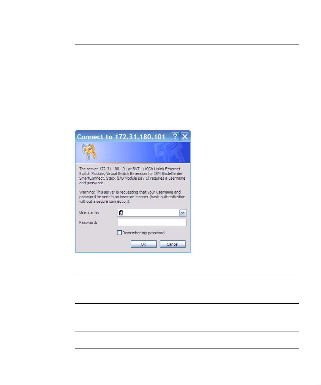
If the switch is configured correctly for BBI access, the login prompt will appear.
3. Log in to the switch.
If the switch and browser are properly configured, the password prompt will appear:
Figure 2-A SmartConnect Login Prompt
Note – The sample screens that appear in this User’s Guid e might differ slightly from the
screens displayed in any given system. Screen content varies based on the type of blade server
chassis being used, the firmware versions and options that are installed, and the specific hardware and software of the system used for accessing the switch.
Enter the account name and password for the switch’s administrator or user account. The
default account name is admin, and the default password is admin.
Note – There may be a slight delay while the main BBI page is being initialized. Do not stop
the browser while loading is in progress.
Chapter 2: Getting Started with the Browser-Based Interface BMD00082, February 2009
18
Page 21
SmartConnect User’s Guide
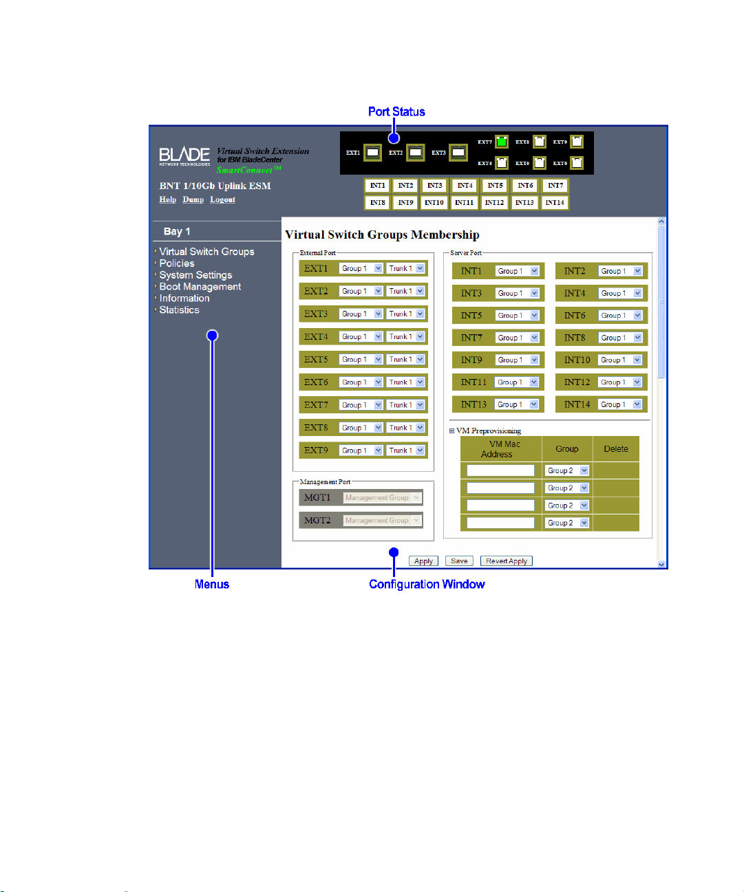
Once the administrator is properly logged in, the VSE SmartConnect software BBI appears in
the Web browser’s viewing window:
Figure 2-B BBI Startup Screen
There are three main regions on the BBI screen:
The port status area is used to view po rt status. Click a port icon to view details.
The menus are used to select particular items or features to act upon.
The configuration window is used to view and configure switch features.
See “BBI Reference” on page 87 for general details on using the BBI.
BMD00082, February 2009 Chapter 2: Getting Started with the Browser-Based Interface
19
Page 22

SmartConnect User’s Guide
Updating the Software Image
The software image is the executable code running on the switch. Upgrading the software
image on the switch typically involves the following actions:
Load a new software image onto a FTP or TFTP server on the network, or onto a local
computer.
Transfer the newly loaded software image to the switch.
Select the new software image to be run when the switch is next reset.
Reset the switch.
Loading the New Software Image
Use the BBI to determine which version of software is currently installed on the switch. On the
BBI menu, choose System Settings > Boot Management > General. The resulting window displays the current software information.
If the switch requires a software update, the latest version of the VSE SmartConnect software
is available from the support web site. Download the switch image and place it on a FTP or
TFTP server, or on a local computer.
Transferring the New Image to the Switch
The switch can store up to two different software images, called image1 and image2, as well as
boot software, called boot. When loading new software, the administrator must specify where
it should be placed: either into image1, image2, or boot.
For example, if the active image is currently loaded into image1, best practice is to load the
new software into image2. This allows the administrator to test the new software and reload
the original active image (stored in image1), if needed.
Note – The switch image type is checked during the software download, to validate that the
image is compatible. If the image is incompatible, an error message is displayed.
The BBI may be used for loading software onto the switch. The software image to load can
reside in one of the following locations:
FTP server
TFTP server
Local computer
Chapter 2: Getting Started with the Browser-Based Interface BMD00082, February 2009
20
Page 23
SmartConnect User’s Guide
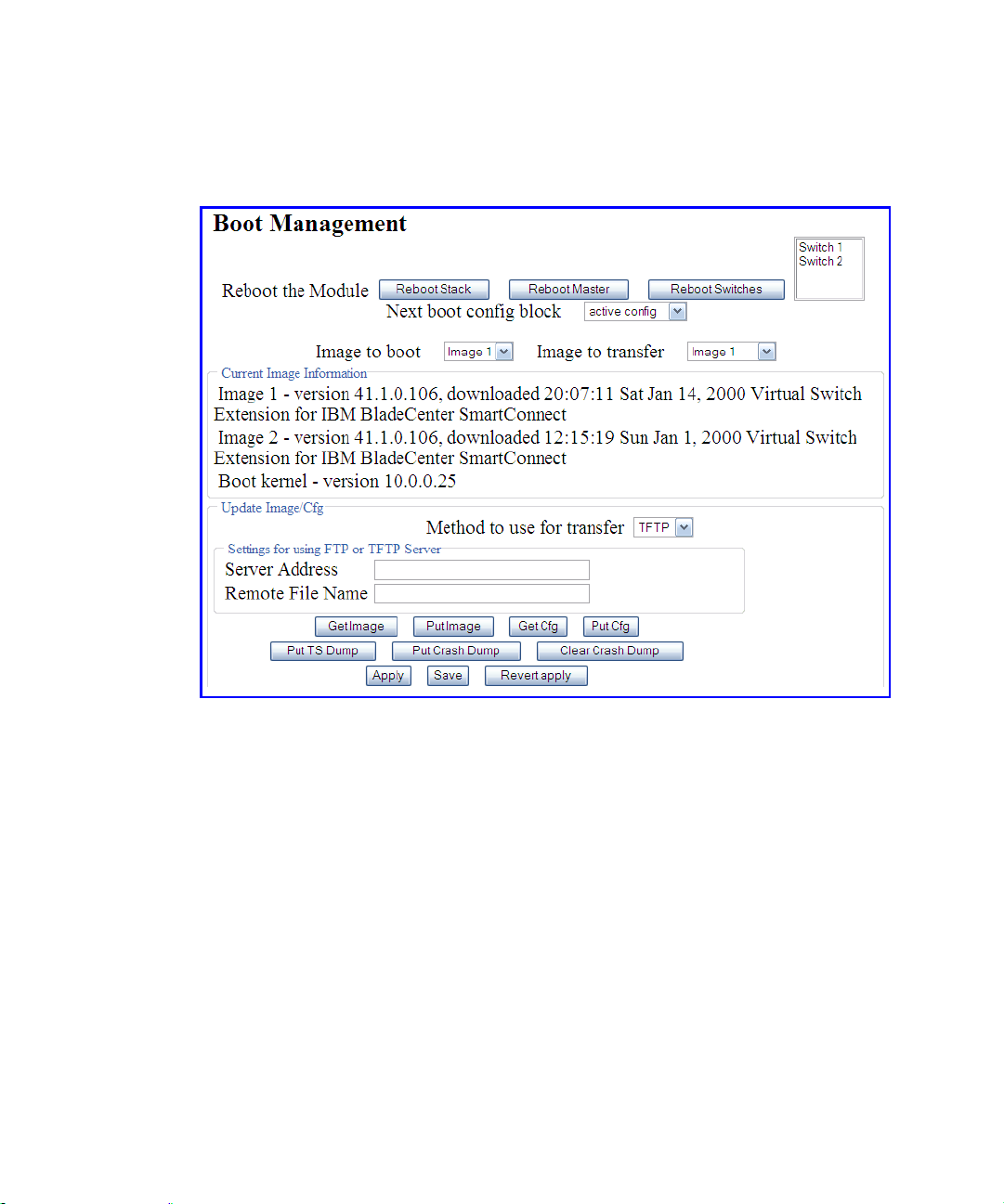
Perform the following steps to load a software image:
1. On the BBI, choose menu System Settings > Boot Management > General.
The Boot Management window appears.
Figure 2-C Boot Management Window (shown with Stacking enabled)
2. Use the Image to transfer drop-down list to select the desired image.
3. In the Update Image/Cfg section, use the Method to use for transfer drop-down list to
specify the desired method (such as TFTP, FTP, or HTTP).
4. Get the image from the appropriate source:
If transferring software from a TFTP server, enter the Server IP Address, and the Remote
File Name. Then click Get Image.
If transferring software from a FTP server, enter the Server IP Address, and the Remote
File Name. Also enter the FTP Username and FTP Password. Then click Get Image.
If transferring software from a local computer (HTTP), click Browse. In the File Upload
dialog, select the desired file and click OK. Then click Get Image.
Once the image is transferred, the page refreshes to show the new software.
BMD00082, February 2009 Chapter 2: Getting Started with the Browser-Based Interface
21
Page 24

SmartConnect User’s Guide
Selecting a Software Image to Run
Perform the following steps t o select which software image (image1 or image2) desired to run
after the next reboot.
1. On the BBI, choose menu System Settings > Boot Management > General.
2. In the Boot Management page, use the Image to boot drop-down list to select the
desired image.
The VSE SmartConnect software can store two different types of software image, as follows:
VSE SmartConnect software image
BNT 1/10Gb Uplink Ethernet Switch Module (GbESM) image
This procedure can be used to change from one image type to the other. However, the configuration block for one image type is not compatible with the other type.
3. If necessary, select an option from the Next boot config block drop-down list.
If the software image type is changed, a compatible configuration block must be loaded or the
configuration must be reset to factory defaults. It is recommended that both the active and
backup configurations remain compatible with the active image type. For example, if a VSE
SmartConnect software configuration file is in the active config, do not store a normal configuration file in the backup config.
Note – When resetting the switch to its factory default configuration, the switch will retain its
stacking settings. To reconfigure or disable stacking, see “Stacking” on page 43.
4. Click Apply to submit the image and configuration changes to the switch.
The changes will remain pending until the switch is next reset.
5. Click Reboot the Module to activate the new image file and configuration block.
Uploading a Software Image from the Switch
Software images can also be uploaded from the switch to a FTP or TFTP server. The same
software can then be transferred to other compatible switches.
Perform the following steps to upload a software image from the switch to a FTP/TFTP server.
1. On the BBI, choose menu System Settings > Boot Management > General.
In the Boot Management window, page appears.
2. Use the Image to transfer drop-down list to select the desired image.
Chapter 2: Getting Started with the Browser-Based Interface BMD00082, February 2009
22
Page 25

SmartConnect User’s Guide
3. In the Update Image/Cfg section, use the Method to use for transfer drop-down list to
specify the desired method.
4. Get the image from the appropriate source:
If loading a software image to a TFTP server, enter the Server IP Address, and the Remote
File Name. Then click Put Image.
If loading a software image to a FTP server, enter the Server IP Address, and the Remote
File Name. Also enter the FTP Username and FTP Password. Then click Put Image.
If loading a software image to a local computer (HTTP), click Browse. In the File Upload
dialog, select the desired file and click OK. Then click Put Image.
Selecting a Configuration Block
When configuration changes are made to the switch, the administrator must save the changes so
that they are retained beyond the next time the switch is reset. When the save command is
issued, the new configuration changes are placed in the active configuration block. The previous configuration is copied into the backup configuration block.
There is also a factory configuration block. This holds the default configuration of the VSE
SmartConnect software. Under certain circumstances, it may be desirable to reset the switch
software to its default configuration.
Perform the following steps to select which configuration block the switch will load the next
time it is reset:
1. On the BBI, choose menu System Settings > Boot Management > General.
2. In the Boot Management window, select an option in the Next boot config block
(active, backup, or factory).
Note – When resetting the switch to its factory default configuration, the switch will retain its
stacking settings. To reconfigure or disable stacking, see “Stacking” on page 43.
3. Click Apply to submit the configuration block changes to the switch.
The changes will remain pending until the switch is next reset.
4. Click Reboot the Module to activate the new configuration block.
BMD00082, February 2009 Chapter 2: Getting Started with the Browser-Based Interface
23
Page 26

SmartConnect User’s Guide
Resetting the Switch
The switch must be reset to make the software image file and configuration block changes
active. To reset the switch module:
1. On the BBI, choose menu System Settings > Boot Management > General.
The Boot Management page appears.
2. Click Reboot the Module.
Chapter 2: Getting Started with the Browser-Based Interface BMD00082, February 2009
24
Page 27

CHAPTER 3
Switch Virtualization
The following virtualization features are included in the VSE SmartConnect software:
VMready
The switch’s VMready software makes it virtualization aware. The switch automatically
discovers the Virtual Machines (VMs) of hypervisors connected to internal ports on the
switch. The VSE SmartConnect software accepts up to 1024 VMs.
Virtual aggregation
Switch resources can be pooled together, combining their capacity while at the same time
simplifying their management. This can be accomplished on a number of levels:
Grouping multiple internal and external switch ports into a single, logical switching
entity with shared bandwidth capacity. Up to 32 such Virtual Switch Groups (VSGs)
can be configured on the switch or stack.
Trunking multiple switch ports into a single, high-bandwidth link to other networking
devices. Each VSG supports up to two external trunks which can be used indepen-
dently, or as a primary and backup.
Stacking multiple switches from the same or different chassis into a single super-
switch. VSE SmartConnect software supports one stack with up to eight switches.
Stacking also permits the use of up to 56 internal port trunks.
Virtual segmentation
VSGs act as independent logical units. Traffic assigned to different VSGs is thoroughly
separated within the switch, essentially dividing the switch into smaller switch entities.
VSG segmentation occurs internally within the switch, requiring no support changes to the
broader network configuration (such as VLANs). Internal and external switch ports, as
well as any attached VMs, can be independently assigned to VSGs.
ServerMobility
The ServerMobility feature allows server IP addresses to be assigned based on their physical location in a blade server chassis. Then, if a server fails, a replacement server (in the
same or different slot) can assume the identity (and configuration) of the failed unit.
™
By combining virtualization features, VSE SmartConnect software provides a highly-flexible
framework for allocating and managing switch resources.
BMD00082, February 2009 25
Page 28

SmartConnect User’s Guide
Virtual Switch Groups
Switch resources can be assigned to VSGs. Up to 32 VSGs are available. Each VSG behaves
independently, which allows for segmenting the switch into smaller logical entities. Within
each VSG, member ports can be aggregated into trunks, combining their bandwidth.
T wo different types of resources can be assigned to VSGs:
Ports (internal and external)
VMs
Port Groups
Each internal and external port can be independently assigned to one of the 32 available VSGs.
Each VSG can contain multiple ports, but each port can belong to only one VSG.
VSGs for port groups must have the following characteristics:
It is recommended that each VSG contain internal server ports and external ports for
proper network operation.
By default, all external ports in the same VSG are placed into one trunk to aggregate their
bandwidth. For more information, see “Trunking” on page 30.
For VSG port group and trunk configuration, see “Assigning Ports to VSGs” on page 97.
Virtual Machine Groups
The switch automatically discovers VMs that reside in the hypervisor directly connected to the
switch. As with ports, VMs can be independently assigned to VSGs in order to group or separate them. Optionally, uplink ports can also be assigned to VSGs that include VMs.
The switch will accept a maximum of 1024 VMs. Once this limit is reached, the switch will
reject additional VMs.
Note – In some rare situations, the switch may reject the addition of new VMs prior to reach-
ing the 1024 VM limit. This can occur when the hash bucket corresponding to the new VM is
already full. If this occurs, change the virtual machine’s MAC address and retry the operation.
The MAC address can usually be changed from the virtualization platform’s management console (such as the VMware Virtual Center). This limitation is independent of whether switches
are acting alone or as part of a stack.
Chapter 3: Switch Virtualization BMD00082, February 2009
26
Page 29

SmartConnect User’s Guide
VSGs containing VMs have the following characteristics:
The VSG may consist of VMs and (op tio nally) external ports.
Internal ports cannot be added to VSGs which contain VMs, and VMs cannot be added to
VSGs which contain internal ports .
The sw itch all ows com munication between VMs in the same group.
The switch does not allow communication between VMs which are not in the same group.
However, VMs which are in the same hypervisor may still communicate with each other
even if they are not assigned to the same VSG on the switch.
For information on configuration, see “Assigning Virtual Machines to VSGs” on page 97.
Link Aggregation
The default network configuration of the VSE SmartConnect software places all ports into a
single VSG, and aggregates all external ports together into a static Link Aggregation Group
(LAG), also known as a trunk (see “Trunking” on page 30).
This configuration eliminates the need for Spanning Tree Protocol to prevent network loops,
since the uplink ports act as a single link. Also, since all of the uplink ports in each VSG participate in a static LAG, if a link fails, the existing traffic is redirected to the other links.
To overri de default VSG assignments and trunk settings, see “Assigning Ports to VSGs” on
page 97).
BMD00082, February 2009 Chapter 3: Switch Virtualization
27
Page 30

SmartConnect User’s Guide
VLANs
Network Segmentation
Virtual Local Area Networks (VLANs) are commonly used to split up groups of network users
into manageable broadcast domains, to create logical segmentation of workgroups, and to
enforce security policies among logical segments.
By default, the VSE SmartConnect software treats all VLAN traffic as regular , untagged traffic
(as if no VLAN is assigned), and does not use VLAN information for making decisions on
whether to forward, drop, or segment traffic.
Switches with VSE SmartConnect software use VSGs to provide similar network segmentation functions without the need to alter the configuration of the broader network.
Though VSG numbers do not technically correlate to any specific VLAN IDs, if VSGs are
used as a way to emulate VLANs in the switch, for ease of management the administrator can
set the name of the VSG to reflect the equivalent VLAN identity.
Port Access
VLAN security policies can be enforced for ports within VSGs by using Access Control Lists
(ACLs). Port ACLs can be configured to consider a packet’s VLAN ID for making decisions
on whether to permit or deny the packet’s ingress.
ACLs can be configured in the BBI through the Switch Policy menus (see “Access Control
Lists” on page 106 and “Access Control List Sets” on page 111), and applied to ports through
the Virtual Switch Groups menu (see “Virtual Switch Groups ACL QoS” on page 100).
Port-Based VLAN Tagging
Each internal and external port can be independently configured with a Port VLAN ID (PVID)
for tagging purposes. Under specific circumstances, the configured VLAN ID will be added to
or stripped from traffic passing through the switch.
Upon the ingress of untagged packets:
If the PVID on the port is 0 (the default), the packets will remain untagged.
If the PVID on the port is set to any value other than 0, the switch will tag the packets,
placing the port’s VLAN identifier into the frame headers. One application of this
feature is to set a VLAN for traffic outbound from servers that do not perform their
own VLAN tagging.
Chapter 3: Switch Virtualization BMD00082, February 2009
28
Page 31

SmartConnect User’s Guide
Upon the ingress of tagged packets:
Packets which are already tagged for specific VLANs prior to reaching the switch are
unchanged (retain their original tag), regardless of the PVID setting on the ingress port.
Upon the egress of untagged packets:
After ingress processing, if the packet is still untagged, it will remain untagged when
egressing the port, regardless of the PVID setting on the egress port.
Upon the egress of tagged packets (whether tagged prior to ingress, or as a result of
ingress processing):
If the PVID on the egress port is different than that of packet’s tag, the packet will
remain unchanged upon egress, retaining it’s current tag.
If the PVID on the egress port matches the packet’s tag, the VLAN tag will be
stripped from the packet header. One application of this feature is to remove tags on
traffic bound for servers that are not configured to support multiple VLANs.
PVIDs can be configured in the BBI through the Switch Policy menus (see “Internal Port Set-
tings” on page 102 and “External Port Settings” on page 103).
Defined VLANs
The VSE SmartConnect software uses the following VLANS:
The default VLAN is an unt agged VLAN used for data traffic, and contains all external
ports and internal server-blade ports.
Individual VLANs can be specified for switch IP Interfaces and stack interface.
If the stacking feature is enabled, VLAN 4090 is reserved for segmenting inter-switch
stacking traffic. Though the default stacking VLAN can be changed, it is strongly recommended that the default VLAN 4090 be used and reserved solely for stacking.
VLAN 4095 is used by the management network, which includes the management ports
and (by default) the internal blade ports. This configuration allows Serial over LAN (SoL)
management, a feature available on certain server blades. VLAN 4095 configuration
cannot be modified.
BMD00082, February 2009 Chapter 3: Switch Virtualization
29
Page 32

SmartConnect User’s Guide
Trunking
Trunks provide super-bandwidth, multi-link connections between switch modules or other
trunk-capable devices. A trunk is a group of ports that act together, combining their bandwidth
to create a single, larger virtual link.
In the VSE SmartConnect software, trunks function as static Link Aggregation Groups (LAGs)
that are compatible with Cisco’s EtherChannel technology.
VSE SmartConnect software supports the following trunk types:
Up to 64 external trunks (2 independent trunks for each of 32 VSGs)
Up to 56 internal trunks are available when multiple switches are placed in a stacked con-
figuration (see “Stacking” on page 43).
For additional limits, see “Trunking Rules” on page 32.
Chapter 3: Switch Virtualization BMD00082, February 2009
30
Page 33

SmartConnect User’s Guide
External Trunks
When using a VSG with multiple external ports, a trunk can be created between the switch
module and another switch. A simple example is shown in Figure 3-A. This provides a virtual
link operating at up to 30G per second, depending on how many physical ports are combined.
Switch
Module
Blade
Server
Chassis
Application Switch
Aggregate
Port Trunk
Figure 3-A Trunking External Ports
The trunk is also useful for connecting a switch module to third-party devices that support link
aggregation, such as Cisco routers and switches with EtherChannel technology (not ISL trunking technology) and Sun's Quad Fast Ethernet Adapter. The switch’s trunking technology is
compatible with these devices when they are configured manually.
Each VSG can have up to two external port trunks. Each of these trunks may consist of as
many external ports as are available in the VSG. By default, the external ports for each VSG
are placed into one of the VSG’s available trunks. If all the switch ports belong to the same
VSG (as with the factory default configuration), all external ports will be placed into the same
trunk, though it is possible that not all links will be active (see “Trunking Rules” on page 32).
Note – Because all external ports in a VSG belong to the same trunk by default, external ports
should not be used as regular IEEE 802.3 network links. Do not plug a workstation directly
into one of the switch’s active external ports unless it is the only device attached to these ports,
or unless the port has been explicitly assigned to a VSG or trunk with no other active external
ports.
To reconfigure the trunk assignment for each external port, see “Virtual Switch Groups Mem-
bership” on page 97.
BMD00082, February 2009 Chapter 3: Switch Virtualization
31
Page 34

SmartConnect User’s Guide
Trunking Rules
The trunking feature operates according to specific rules of operation. When working with
trunks, consider the following rules to determine how a trunk reacts in any network topology:
Trunking to third-party devices must comply with Cisco
®
EtherChannel® technology.
For any specific trunk, only one physical port type can be active at any given time. If ports
of different types (such as 1G ports and 10G ports) are mixed in a trunk (as occurs in the
default configuration), the switch uses the Best Link algorithm to select the best port type
for trunk operation. The lower-speed trunk ports will be automatically disabled while the
higher-speed ports are in operation.
For any specific trunk, although any number of ports can be assigned to the trunk, a maxi-
mum of eight ports may have an active link at any given time. If more than eight ports are
included in a trunk, the switch will automatically disable links on the extra trunk ports
while eight ports are in operation.
Each trunk may consist of internal ports only, or external ports only. Internal and external
ports cannot be mixed in the same trunk.
Each external trunk must consist of member po rts belonging to only one VSG. External
ports for different VSGs cannot be trunked together.
Each external trunk must originate from one logical device (one switch or different
switches in the same stack), and lead to one logical destination device (such as a switch,
stack, or other network device).
In ternal trunks require that stacking is enabled.
Internal trunks may have member ports belonging to one VSG or multiple VSGs.
Each internal trunk may group internal ports from the same switch or multiple switches in
a stack, and may lead to one or more network devices.
Internal trunks do not support VMs that are assigned to VSGs. Trunking ports that include
VSG-assigned VMs, or assigning VSGs to VMs on ports that are already part of an inter-
nal trunk, may cause unexpected behavior.
These rules apply to any switch when operating independently, or to the set as a whole when
multiple switches are placed in a stacked configuration.
Chapter 3: Switch Virtualization BMD00082, February 2009
32
Page 35

SmartConnect User’s Guide
Statistical Load Distribution
Network traffic is statistically distributed between external ports in a trunk. The switch uses
the source and destination IP address information present in each transmitted IP frame to determine load distribution. If the frame is not an IP frame, then Layer 2 MAC addresses are used.
Each packet’s particular combination of source and destination addresses results in selecting
one line in the trunk for data transmission. If there are enough devices feeding the trunked
lines, then traffic distribution becomes relatively even.
Built-In Fault Tolerance
Since trunks are comprised of multiple physical links, each trunk is inherently fault tolerant.
As long as one connection is available, the trunk remains active.
Statistical load distribution is maintained when a port in a trunk is lost or returned to service.
Link Aggregation Control Protocol
Link Aggregation Control Protocol (LACP) is an IEEE 802.3ad standard for grouping several
physical ports into one logical port (known as a dynamic trunk group or Link Aggregation
Group) with any device that supports the standard. Please refer to IEEE 802.3ad-2002 for a full
description of the standard.
The 802.3ad standard allows standard Ethernet links to form a single Layer 2 link using the
Link Aggregation Control Protocol (LACP). If a link in a LACP trunk group fails, traffic is
reassigned dynamically to the remaining link or links of the dynamic trunk.
To configure LACP for a VSG, choose Virtual Switch Groups > Settings in the BBI. The
Link Aggregation Control Protocol field can be used to enable or disable LACP. When
enabled, external ports in the VSG participate in LACP. When disabled (as by default), external ports in the VSG’s external trunk act as a static trunk.
Switch Failover
The primary application for switch failover is to support Network Adapter Teaming. W ith Network Adapter Teaming, the NICs on each server all share the same IP address and are configured into a team. One NIC is the primary link, and the other is a standby. For details, refer to
“Configuring Teaming” in the Broadcom NetXtreme™ Gigabit Ethernet Adapter User Guide.
BMD00082, February 2009 Chapter 3: Switch Virtualization
33
Page 36

SmartConnect User’s Guide
Switch failover is disabled by default, but can be enabled for any VSG. When enabled, switch
failover works as follows:
If some (or all) of the links fail in the failover trigger, the switch disables all internal ports
in the VSG. This causes the NIC team on the affected server blades to failover from the
primary to the backup NIC. This process is called a failover event.
When the appropriate number of links return to service, the switch enables the internal
ports in the VSG. This causes the NIC team on the affected server blades to fail back to the
primary switch (unless Auto-Fallback is disabled on the NIC team). The backup processes
traffic until the primary’s internal links come up, which takes up to five seconds.
Setting the Number of Links to Trigger Failover
The Number of Links to Trigger Failover specifies the minimum number of operational links
in the VSG that triggers a failover event. For example, if the limit is four, a failover event
occurs when the number of operational links in the trigger is four or fewer. If the trigger number is set to zero (0), the switch triggers a failover event only when no links in the VSG are
operational.
Configuring Switch Failover
Figure 3-B is a simple example of switch failover. One switch is the primary, and the other is
used as a backup. In this example, all external ports on the Primary Switch belong to a single
VSG with switch failover enabled, and the number of links to trigger failover set to two. If two
or fewer links in Trigger 1 remain active, the switch temporarily disables all internal serverblade ports. This action causes a failover event on Server 1 and Server 2.
Internet
Enterprise
Routing Switches
Trigger 1
Trigger 1
Blade Server Chassis
Primary
Switch
Backup
Switch
VLAN 1:
VLAN 2:
Server 1
Server 2
Server 3
Server 4
Figure 3-B Basic Switch Failover
On the BBI, choose Virtual Switch Groups > Settings to enable Switch Failover and to configure the Number of Links to Trigger Failover.
Chapter 3: Switch Virtualization BMD00082, February 2009
34
Page 37

SmartConnect User’s Guide
Internal Trunks
Internal trunks allow for more granular high-availability options for the links between the servers and switches within a blade server chassis. Internal trunks have the following requirements:
One or more blade servers in the blade chassis must be installed with multiple NICs and
be configured for NIC Teaming. The actual number of supported NICs depends on the
specific server and chassis model, and the capabilities of the NIC Teaming software.
Multiple SmartConnect switches in the same blade chassis as the servers must be linked
together as part of a stacked configuration (see “Stacking” on page 43). The number of
SmartConnect switches installed in the chassis (and their slot locations) must coincide
with the slots targeted by the blade servers’ NICs.
For additional restrictions, see “Trunking Rules” on page 32.
Figure 3-C shows a high-availability network combining external and int e rnal trun ks in a
stacked switch configuration.
External
Uplink Trunks
Trunk
Internet
Trunk
Enterprise
Routing Switches
Figure 3-C Trunking Inte rnal Ports
Stacked Switches
& Support Links
Master
Switch
Member
Switch
Blade Server Chassis 1
Member
Switch
Member
Switch
Blade Server Chassis 2
Internal
Trunks
Servers with
Teamed NICs
Server
Server
Server
Server
Server
Server
Server
Server
BMD00082, February 2009 Chapter 3: Switch Virtualization
35
Page 38

SmartConnect User’s Guide
In Figure 3-C, the two external trunks provide aggregation to the exterior network, and also
high-availability in case any single uplink cable, external port, switch module, or blade chassis
fails. On the service side of the network, each server includes two NICs which are automatically connected to each of the switch modules within its blade chassis. Both internal switch
ports leading to each specific server are trunked together, despite belonging to different
switches in the stack. Each server is configured for NIC Teaming so that if either NIC or
switch module fails, the connection to the other switch is maintained using the same server IP
address.
Alternate configurations are possible. Internal trunks do not require that trun ked ports belong
to the same VSG. Also, internal trunks may include multiple ports form any specific switch
(individually or as part of the stack).
By default, all internal ports are excluded from trunks. To assign internal ports to trunks, see
“Internal Trunk ID” on page 102.
IGMP Snooping
IGMP Snooping allows the switch to forward multicast traffic only to those ports that request
it. IGMP Snooping prevents multicast traffic from being flooded to all ports. The switch learns
which server hosts are interested in receiving multicast traffic, and forwards it only to ports
connected to those servers.
By default, the switch floods unregistered IP multicast (IPMC) packets to all ports.
On the BBI, choose Virtual Switch Groups > Settings to enable IGMP Snooping for the
desired VSG. The default value for all VSGs is enabled.
Chapter 3: Switch Virtualization BMD00082, February 2009
36
Page 39

SmartConnect User’s Guide
ServerMobility
The ServerMobility™ feature allows server IP addresses to be assigned based on their physical
location in a blade server chassis. If a server fails, a replacement server can assume the identity
of the failed unit. The replacement can be a new blade server placed into the slot of the failed
unit, or it can be a backup server in another slot, that is activated to take over for the failed
server.
The ServerMobility feature uses DHCP option 82 to support fixed server address allocation.
When the switch relays a server’s DHCP request, it inserts the chassis ID, slot number, and
port number into the request, as follows:
The chassis ID is encoded in the Agent circuit ID sub-option, in hexadecimal format,
as follows:
59:49:00:c1:56:5f:11:db:a8:dd:ca:d0:a4:b3:de:4a
The slot number and port number are encoded in the Agent remote ID sub-option,
in hexadecimal format. The following example shows how Slot 1 and Port Number 2 are
configured in the Agent remote ID:
01:0:0:0:02
The DHCP server must be configured to supply a reserved IP address for each server , based on
the option 82 information.
Note – The ServerMobility feature operates independently of the SmartConnect features that
may be installed on the chassis. ServerMobility should not be enabled on the switch if SmartConnect server failover features have already been enabled on the chassis management system.
Configuring a Backup Server Port
If one server is configured as the backup to another server, the administrator may wish the two
servers to use the same IP address, even though they are in different slots. To address this
issue, configure a port as the backup port of another (active) port on the switch. The agent
remote ID sub-option for packets received on the backup port will use the port number of its
active port. If the active server goes down, the backup server will receive the same IP address
as the active server.
The following configuration guidelines apply to ServerMobility backup ports:
Both the active port and the backup port must have the ServerMobility feature enabled.
The active po rt and the backup port must be in the same VSG.
BMD00082, February 2009 Chapter 3: Switch Virtualization
37
Page 40

SmartConnect User’s Guide
General Configuration
T o configure the ServerMobility feature, choose Policies > Server Mobility > General Configuration.
Figure 3-D ServerMobility General Configuration Window
The following table describes the general options for the ServerMobility feature.
Table 3-1 ServerMobility General Configuration Fields
Field Description
ServerMobility State Enables or disables the ServerMobility feature on the switch.
Relay on Non-
Server-Mobility Ports
Set ServerMobility configu-
ration to factory default
Chapter 3: Switch Virtualization BMD00082, February 2009
38
Enables or disables BOOTP Relay for all ports that have the ServerMobility feature disabled.
Resets ServerMobility parameters to factory default values.
Page 41

SmartConnect User’s Guide
Port Configuration
To configu re ports for the ServerMobility feature, choose Policies > Server Mobility > Port
Configuration.
Figure 3-E ServerMobility Port Configuration Window
The following table describes the ServerMobility feature options for each port on the switch.
Table 3-2 ServerMobility Port Configuration Fields
Field Description
Port Identifies each port in the switch.
Port ServerMobility
Mode
Port DHCP request fil-
tering mode
Backup port Selects a backup port. The blade server connected to the backup port acts as
Enables or disables the ServerMobility feature on the port. When enabled,
DHCP option 82 information is forwarded to the DHCP server.
Enables or disables filtering DHCP request information on the port. When
enabled, DHCP requests from the blade server are filtered, so that the DHCP
server receives only DHCP requests from the switch.
Note: If the ServerMobility feature is enabled on a port, it is recommended
that DHCP request filtering also be enabled.
a backup to the server connected to this port. The backup server uses the
same IP address as the active server.
Note – For port numbers, if the switch is part of a multi-switch stack, the displayed number
indicates the Configured Switch number (csnum) followed by the port number. See “Stacking
Port Numbers” on page 54 for more information.
BMD00082, February 2009 Chapter 3: Switch Virtualization
39
Page 42

SmartConnect User’s Guide
DHCP Server Configuration
To modify the DHCP server configuration, open the configuration file (dhcpd.conf), and
add new classes for server ports. Then define an IP address for each class.
For Linux DHCP servers, option 82 information is referenced by the following variables:
option agent.circuit-id
option agent.remote-id
These variables can be used in any expression allowed within a DHCP configuration file. To
declare an explicit chassis, configure the chassis ID in agent.circuit-id.
This configuration declares a class for the server connected to port 8 of a switch in slot 1 of
chassis 5949 00C1 565F 11DB A8DD CAD0 A4B3 DE4A
class “class-chassis1-slot1-port8”
{
match if option agent.circuit-id =
59:49:00:c1:56:5f:11:db:a8:dd:ca:d0:a4:b3:de:4a
and option agent.remote-id = 01:0:0:0:08; }
This configuration associates an IP address with the class declared above.
subnet 10.70.70.0 netmask 255.255.255.0 {
pool
{
allow members of "class-chassis1-slot1-port8"; range 10.70.70.10; }
}
Chapter 3: Switch Virtualization BMD00082, February 2009
40
Page 43

SmartConnect User’s Guide
In the following example, one new class is added to define server port 8, then an IP address is
associated with the new class:
******CLASS******
# in this class I have defined a switch in chassis with ID
# 59:49:00:c1:56:5f:11:db:a8:dd:ca:d0:a4:b3:de:4a
# placed in slot 1 and blade server is connected in port 8
class "class-chassis1-slot1-port8"
{
match if option agent.circuit-id =
59:49:00:c1:56:5f:11:db:a8:dd:ca:d0:a4:b3:de:4a
and option agent.remote-id = 01:0:0:0:08; }
******Range for that class*********
# for class-chassis1-slot1-port8 only one IP
# is defined (10.70.70.10)
subnet 10.70.70.0 netmask 255.255.255.0 {
pool
{
allow members of "class-chassis1-slot1-port8"; range 10.70.70.10; }
}
This example was performed with Internet Systems Consortium DHCP Server, version 3.0.4.
BMD00082, February 2009 Chapter 3: Switch Virtualization
41
Page 44

SmartConnect User’s Guide
Chapter 3: Switch Virtualization BMD00082, February 2009
42
Page 45

CHAPTER 4
Stacking
A stack is a group of up to eight switches with VSE SmartConnect software that work together
as a unified system. A stack has the following properties, regardless of the number of switches
included:
The network views the stack as a single entity, and the stack is identified by a single net-
work IP address.
Sw itches in a stack may reside within a single blade server chassis, or in multiple chassis.
The number of ports in a stack equals the total number of ports of all the switches that are
part of the stack.
The maximum number of Virtual Switch Groups (VSGs) remains 32 (the same as for a
non-stacked switch), though the number of ports which can be placed in any VSG is equal
to the total number of ports in the stack.
The maximum number of Virtual Machines (VMs) remains 1024 (the same as for a non-
stacked switch).
The maximum number of external trunks remains 64 (2 for each of the 32 VSGs) though
the number of ports which can participate in any trunk is equal to the total number of ports
in the stack.
The maximum number of internal trunks is 56.
The stack is managed through the Master switch. Use Telnet or the Browser-Based Interface
(BBI) to access the Master, as follows:
On any switch in the stack, connect to any external port that is not part of an active trunk
(see the note on page 31), and use the IP address of the Master to access the Master switch.
Use the management IP address assigned to the Master by the management system .
The Master switch pushes configuration changes and run-time information to the Member
switches.
BMD00082, February 2009 43
Page 46

SmartConnect User’s Guide
Stacking Requirements
Before switch modules can form a stack, they must meet the following requirements:
All switches must be the same type.
All blade server chassis must be the same type or have the same number of server slots
(for example, BCE and BCH chassis types are compatible for stacking).
Each switch must be installed with VSE SmartConnect software. The same release version
is not required, as the Master switch will push a firmware image to each differing switch
in the stack.
It is recommended that two 10Gb external ports on each switch are dedicated to stacking.
External ports 17 and 18 are used by default, though this can be changed during configura-
tion if necessary. The cables used for connecting the switches in a stack carry low-level,
inter-switch communications critical to shared switching functions. Always maintain the
stability of stack links in order to avoid internal stack reconfiguration.
Stack Membership
A stack contains up to eight switches, interconnected by a stack trunk in a ring topology. With
this topology, only a single stack link failure will be allowed. The stack contains one Master
and one or more Members, as follows:
Master
One switch controls the operation of the stack and is called the Master. The Master provides a
single point to manage the stack. A stack must have one and only one Master. Firmware image,
configuration information, and run-time data are kept by the Master and pushed to each switch
in the stack.
Member
Member switches can reside within a single blade server chassis or across multiple chassis.
Members receive configuration changes, run-time information, and software updates from the
Master.
Backup
One member switch can be designated as a Backup to the Master. The Backup takes over control of the stack if the Master fails. Configuration information and run-time data are synchronized with the Master.
Chapter 4: Stacking BMD00082, February 2009
44
Page 47

SmartConnect User’s Guide
Master and Backup Selection
A stack has only one Master and one Backup. The Master election is based on priority value
and MAC address. If the priority values of two Current Masters are the same, then the one with
lower MAC address becomes the Current Master for the stack. Priority is assigned internally
by how the switch is configured and its changing role in the stack, as follows:
Designated Master
A Designated Master boots up with priority base value of 150. If there is no Master for the
stack, then it is promoted to 225, the highest priority value for stacking. If the Designated
Master fails, then the Designated Backup becomes the new Master. When the Designated
Master rejoins the stack, it has priority 175 as the Current Backup.
Designated Backup
The Designated Backup boots up with priority base value of 125. When it joins a stack
with an existing Master, it becomes the Current Designated Backup with priority value of
175. If it becomes the new Master, then its priority value is 200, for the role of Current
Master.
Members
Each Member has a priority value of 100. The Designated Master (150) and Designated
Backup (125) can assume the role of Member, due to some stack event changes (for example, merging stacks), but they still carry their base priority values.
With the above priority scheme, the Current Designated Master (225) will never be replaced by
another Designated Master (150), even if the joining Designated Master has a low MAC
address. The election process also ensures that the Current Designated Master (225) remains
the Current Master, even if another Current Master (originated from the same stack as Designated Backup with priority 200) joins the stack. The newly joined Master compares its configuration with the Current Master to determine if a reboot of itself is necessary.
Only the Designated Master can set the backup bit in the NVRAM of the Backup. The backup
bit can be cleared by:
By deleting or changing the Backup using the following command from the Designated
Master: /cfg/stack/backup
Another Backup is present in the same stack.
The Current Designated Master reboots with boot config set to factory default.
So the Designated Backup that replaces a failed Current Master (becomes the new Current
Master) keeps its backup bit on. This new Current Master cannot change the backup bit of
another switch, because it is not the Designated Master.
BMD00082, February 2009 Chapter 4: Stacking
45
Page 48

SmartConnect User’s Guide
Only the Designated Master can change the backup bit. So it is necessary to bring back the
original Designated Master in order to make this change (/c/stack/backup). Because of
the backup bit setting, the result of merging two stacks will always result in one Master and
one Member at all times.
Master and Backup Behavior
When a group of switches are rebooted in stacking mode, the Designated Master switch
becomes the Master of the stack. If the Designated Master switch is not present, then all
switches in the stack are placed in a WAITING state until a Master appears. During this WAITING period, all external and server ports of these Member switches are placed into operatordisabled state. Without the Master, a stack cannot respond correctly to a networking event.
When the Master switch is present, it controls operation of the stack. The configuration of the
Master is pushed to the other switches in the stack.
If the Master switch fails, the Backup switch becomes the new Master and the stack continues
to operate normally. If the Backup switch is not available, all the switches in the stack reboot
and wait for a new stack to form.
After the Designated Master switch reboots, if another Master is already present in the stack,
the Designated Master does not become the stack Master. Instead, th e Designated Master
becomes the Backup if instructed by the Current Master. It can become the Master only if the
Current Master fails.
Chapter 4: Stacking BMD00082, February 2009
46
Page 49

SmartConnect User’s Guide
Stack Member Numbers
Each switch in the stack has two numeric identifiers, as follows:
Attached Switch number (asnum)
The asnum identifies each switch based on its physical connection in relation to the
Master.
Configured Switch number (csnum):
The csnum is configured by the stack administrator in order to create a logical grouping of
switches and ports.
It is recommended that asnum 1 and csnum 1 be used for identifying the Master switch.
Note – By default, csnum 1 is assigned to the Master. If csnum 1 is not available, the lowest
available csnum is assigned to the Master.
Configuring a Stack
This section provides procedures for creating a stack of switch modules. The high-level
procedure is as follows:
Enable stacking on each switch.
Designate one switch as the Master.
Reboot all stack switches.
Connect the stack trunk as shown in Figure 4-A.
Configure the Master interface.
Config ure additional stacking parameters on the Master.
BMD00082, February 2009 Chapter 4: Stacking
47
Page 50

SmartConnect User’s Guide
Configuring Each Switch
T o pre-configure each Member switch for stacking, use the CLI to perform the following steps.
1. Enable stacking on each Member switch module in the stack.
>> /boot/stack/enable
2. Configure the Stack Trunk ports (optional).
Dedicate two external 10Gb ports on each switch to support stacking. It is recommended that
the default stack ports be used (shown below).
>> Boot Stacking# stktrnk
Enter ports one per line, NULL at end:
> 17
> 18
>
A Reboot is required for the new settings to take effect
3. Configure the stacking VLAN (optional).
Although any VLAN may be defined for stack traffic, it is highly recommended that the
default, VLAN 4090, be reserved for stacking (shown below).
>> Boot Stacking#
vlan 4090
4. Set the stacking mode.
By default, each switch is set to member mode. However, one (and only one) switch must be
set to master mode. Use the following CLI command on only the designated Master switch:
>> Boot Stacking# mode master
Note – If any Member switches are incorrectly set to master mode, use the mode Member
command to set them back to Member mode.
5. Reboot all of the stack switch modules.
Chapter 4: Stacking BMD00082, February 2009
48
Page 51

SmartConnect User’s Guide
6. Physically connect the Stack Trunks in a bidi rectional ring topology.
It is recommended that two 10Gb external ports on each switch are dedicated to stacking. As
shown in Figure 4-A, starting with the Master switch, connect each switch in turn to the next.
Connect the last Member switch back to the Master to complete the ring.
Switches
connected in
bidirectional
ring topology
Master
Switch
Member
Switch
Blade Server Chassis 1
Member
Switch
Member
Switch
Blade Server Chassis 2
Server
Server
Server
Server
Server
Server
Server
Server
Figure 4-A Example of Stacking Connections
Once the stack trunks are connected, the switches perform low-level stacking configuration.
Note – It is recommended not to disconnect and reconnect the stack links after the stack is
formed. If the stack links are disconnected, stack operation can become unstable as the stack
reconfigures, and traffic can be disrupted, causing data loss.
7. On the designated Master switch, configure the Master interface for the stack.
>> # cfg/stack/mif
>> Master Switch Interface# addr 10.10.1.1
>> Master Switch Interface# mask 255.255.0.0
>> Master Switch Interface# gw 10.10.20.2
Note – The mif menu is available only on the Master switch once the stacking mode has been
set (Step 4) and the switch has been rebooted (Step 5).
BMD00082, February 2009 Chapter 4: Stacking
49
Page 52

SmartConnect User’s Guide
Additional Master Configuration
Once stacking is enabled on each switch, connect the stack trunk, and define the Master switch
interface, use the BBI to access the Master switch using the internal management IP interface
of the Master switch, and complete the configuration.
Locating the Master Switch Internal Management IP Interface
To launch the BBI for the Master switch, use a Web browser to access the Master interface IP
address configured in Step 7 of the previous procedure.
Alternately, the Advanced Management Module can be used. To locate the IP address of the
Master switch, go to the System St atus Summary > I/O Modules, and use the address of the
switch identified as the master in the Stacking column.
To launch the BBI from within the Advanced Management Module, go to I/O Module
Tasks > Configuration, select the target switch and click Advanced Configuration. In the
Advanced Configuration window, under Start Telnet/Web Session, click on the Start Web
Session button.
Viewing Stack Connections
From the Master switch BBI menu, choose Information > Stack and locate the Attached
Switch Information. Make sure all of the stack switches are listed. If a switch is not listed,
check the cables on the stack links, and make sure all stacking requirements are met, as listed
in “Stacking Requirements” on page 44.
Figure 4-B Attached Switch Information Window
Chapter 4: Stacking BMD00082, February 2009
50
Page 53

SmartConnect User’s Guide
Binding Members to the Stack
Choose menu System Settings > S tacking > Switch Configuration. The Stack Switch Con-
figuration window appears, as shown in Figure 4-C.
Figure 4-C Stack Switc h Configuration Window
Each switch in the stack is represented by an Attached Switch Number (asnum) and a Configured Switch Number (csnum) as explained in “V iewing S tack Connections” on page 50. Both
asnum 1 and csnum 1 are reserved for the Master.
Select an attached switch in the Bind asnum drop-d own li st to bind the switch to it’s asso-
ciated csnum.
In the B a ckup Switch drop-down list, select a csnum for a Backup switch (optional)
which will assume the Master role if the Master switch should fail.
In the Stack Name field, enter a name for the stack (opti onal ).
The UUID and Bay Number fields display information about the location of configured
switches and are not configurable. The UUID is the Unit ID number of the blade server chassis
where the switch resides, and the Bay Number is the switch’s physical bay within the chassis.
Click Apply to make the changes active, and Save to retain changes beyond reboot cycles.
BMD00082, February 2009 Chapter 4: Stacking
51
Page 54

SmartConnect User’s Guide
Configuring an External IP Address for the Stack
Choose menu System Settings > Stacking > IP Interfaces. Use the Stack IP Interfaces window to configure a single IP interface for the stack. This interface is known at the Master interface and is shared by all switches in the stack.
Figure 4-D Stack IP Interfaces Configuration Window
Enter the following information for the Master Switch Interface:
Master interface IP address and subnet mask
Virtual Switch Group number
VLAN number used for external access to the stack (rather than the internal VLAN 4090
used for inter-stack traffic)
Default gate way IP ad dress
Click Apply to make the changes active, and Save to retain changes beyond reboot cycles.
Note – The Backup switch interface is provided for historical purposes only and should be left
unconfigured. If a Backup switch interface is defined in this window, and th e Master fails, the
stack IP address will change to the IP address configured for the Backup switch interface.
Chapter 4: Stacking BMD00082, February 2009
52
Page 55

SmartConnect User’s Guide
Managing a Stack
When switches are configured into a stack, the BBI displays information for the stack.
The BBI menu area displays the csnum for the Master and the Backup (if configured). The
port status area display includes a switch selector and enhanced port displays, as shown below:
Switch selector
Selected switch:
External ports status
Selected switch:
Internal ports status
Figure 4-E Port Status with Stacking
Click a highlighted switch in the switch selector to display status information about ports in
that switch. Click a port icon to display port statistics.
The following additional configuration changes occur when switches are stacked.
BMD00082, February 2009 Chapter 4: Stacking
53
Page 56

SmartConnect User’s Guide
Stacking Port Numbers
Once a stack is configured, the manner in which port numbers are displayed changes throughout the BBI. Instead of the single number, the csnum appears in front of each port number . For
example:
This numbering change appears in the port status area at the top of the BBI, as well as on
numerous configuration pages. For example:
Virtual Switch Groups > Membership
Policies > External Port Settings
Policies > Internal Port Settings
Policies > ServerMobility > Port Configuration
On these BBI configuration pages, the administrator can also select whether to display all ports
for all switches, all present switches, all defined switches, or a specific csnum. To do this,
make the appropriate selection from the View Ports drop-down list.
Stacking Internal Port Settings
For each port in a stack, the following command is added to the Internal Port Settings window:
Table 4-1 Additional Internal Port Settings for Stacking
Field Description
Internal trunk id
<1-56, 0 = none>
Configures the trunk ID for internal ports. Ports in the same VSG that have the
same internal trunk ID form a trunk.
Stacking VLANs
VLAN 4090 is the default VLAN reserved for stacking ports.
Note – Do not use VLAN 4090 for any purpose other than stacking.
Chapter 4: Stacking BMD00082, February 2009
54
Page 57

SmartConnect User’s Guide
Stacking Boot Management
The Boot Management General window provides controls that allow the administrator to perform a reboot of individual switches in the stack, or the entire stack. The following table
describes the stacking Reboot commands.
Table 4-2 Stacking Boot Management buttons
Field Description
Reboot Stack Performs a software reboot/reset of all switches in the stack. The software
image specified in the Image To Boot drop-down list becomes the active
image.
Reboot Master
Reboot Switches Performs a reboot/reset on selected switches in the stack. Select one or more
Performs a software reboot/reset of the
specified in the Image To Boot drop-down list becomes the active image.
switches in the drop-down list, and click Reboot Switches. The software
image specified in the Image To Boot drop-down list becomes the active
image.
The Update Image/Cfg section of the window applies to the Master. When a new software
image or configuration file is loaded, the file first loads onto the Master, and the Master pushes
the file to all other switches in the stack, placing it in the same software or configuration bank
as that on the Master. For example, if the new image is loaded into image 1 on the Master
switch, the Master will push the same firmware to image 1 on each Member switch.
Master switch. The software image
Upgrading Stack Software
Upgrade all stacked switches at the same time. The Master controls the upgrade process. Use
the following procedure to perform a software upgrade.
1. Load new software on the Master. Refer to “Transferring the New Image to the Switch”
on page 20.
The Master pushes the new software image to all Members in the stack, as follows:
If the new software is loaded into image 1, the Master pushes the software into image 1 on
all Members.
If loaded into image 2, the Master pushes the software into image 2 on all Members.
The software push can take several minutes to complete.
BMD00082, February 2009 Chapter 4: Stacking
55
Page 58

SmartConnect User’s Guide
2. Verify that the software push is complete. Use either the CLI or the BBI:
From the BBI, go to Information > Stack and view the Image Push Status Information at
the bottom of the page, or
From the CLI, use following CLI command to verify the software push:
/info/stack/pushstat
Image 1 transfer status info:
Switch 00:16:60:f9:33:00:
last receive successful
Switch 00:17:ef:c3:fb:00:
not received - file not sent or transfer in progress
Image 2 transfer status info:
Switch 00:16:60:f9:33:00:
last receive successful
Switch 00:17:ef:c3:fb:00:
last receive successful
Boot image transfer status info:
Switch 00:16:60:f9:33:00:
last receive successful
Switch 00:17:ef:c3:fb:00:
last receive successful
Config file transfer status info:
Switch 00:16:60:f9:33:00:
last receive successful
Switch 00:17:ef:c3:fb:00:
last receive successful
3. Reboot all switches in the stack. From the BBI, select System Settings > Boot Man-
agement. Click Reboot Stack.
4. Once the switches in the stack have rebooted, verify that all of them are using the same
version of firmware. Using the BBI, open Information > Stack and view the Switch
Firmware Versions Information.
Chapter 4: Stacking BMD00082, February 2009
56
Page 59

CHAPTER 5
Command Reference
The VSE SmartConnect software provides a default configuration that is ready to perform
basic switching functions. Some of the more advanced features, however, require administrative configuration before they can be used effectively.
The administrator can use the VSE SmartConnect software BBI to perform most basic configuration tasks. However, the command line interface is the most direct method for collecting
information and making configuration changes. Using a basic terminal, the administrator is
presented with a hierarchy of menus that enable one to view information and statistics about
the switch, and to perform any necessary configuration.
The various commands have been logically grouped into a series of menus and sub-menus.
Each menu displays a list of commands and sub-menus that are available, along with a
summary of each command. Below each menu is a prompt where you can enter appropriate
commands.
You can view configuration information for the switch in both the user and administrator command
modes.
This chapter discusses how to use the command line interface for the VSE SmartCon-
nect software.
This chapter provides an overview of menu commands.
BMD00082, February 2009 57
Page 60

SmartConnect User’s Guide
CLI Menus
The Main Menu appears after a successful connection and login. The following table shows
the Main Menu for the administrator login. Some features are not available under the user
login.
[Main Menu]
info - Information Menu
stats - Statistics Menu
cfg - Configuration Menu
oper - Operations Command Menu
boot - Boot Options Menu
maint - Maintenance Menu
diff - Show pending config changes [global command]
apply - Apply pending config changes [global command]
save - Save updated config to FLASH [global command]
revert - Revert pending or applied changes [global command]
exit - Exit [global command, always available]
Menu Summary
Information Menu
The Information Menu (/info) allows you to display information about the current status of the switch
[Information Menu]
sys - System Information Menu
l2 - Layer 2 Information Menu
l3 - Layer 3 Information Menu
link - Show link status
port - Show port information
transcvr - Show Port Transceiver status
group - Show group information
dump - Dump all information
.
Chapter 5: Command Reference BMD00082, February 2009
58
Page 61

SmartConnect User’s Guide
Statistics Menu
The Statistics Menu (/stats) allows you to view performance statistics for the switch.
[Statistics Menu]
port - Port Stats Menu
clrports - Clear stats for all ports
l2 - Layer 2 Stats Menu
l3 - Layer 3 Stats Menu
mp - MP-specific Stats Menu
ntp - Show NTP stats
dump - Dump all stats
Configuration Menu
The Configuration Menu (/cfg) allows an administrator to configure switch parameters.
Configuration changes are not active until explicitly applied. You can save changes to
non-volatile memory.
[Configuration Menu]
sys - System-wide Parameter Menu
port - Port Menu
global - Global Menu
group - Group Menu
pmirr - Port Mirroring Menu
dump - Dump current configuration to script file
ptcfg - Backup current configuration to FTP/TFTP server
gtcfg - Restore current configuration from FTP/TFTP server
Operations Menu
The Operations Menu (/oper) is used for making immediate, temporary changes to the
operational configuration of the switch. For example, you can immediately disable a port
(without the need to apply or save the change), with the understanding that when the
switch is reset, the port returns to its normally configured operation.
[Operations Menu]
port - Operational Port Menu
prm - Protected Mode Menu
passwd - Change current user password
clrlog - Clear syslog messages
ntpreq - Send NTP request
BMD00082, February 2009 Chapter 5: Command Reference
59
Page 62

SmartConnect User’s Guide
Boot Options Menu
The Boot Options Menu (/boot) is used for upgrading switch software, selecting configuration blocks, and for resetting the switch when necessary.
[Boot Options Menu]
image - Select software image to use on next boot
conf - Select config block to use on next boot
gtimg - Download new software image via FTP/TFTP
ptimg - Upload selected software image via FTP/TFTP
reset - Reset switch
cur - Display current boot options
To use the Boo t Opti ons Menu, you m ust be logged in as the administrator. The Boot
Options Menu provides options for:
Selecting a software image to be used when the switch is next reset
Selecting a configuration block to be used when the switch is next reset
Downloading or uploading a new software image to the switch via FTP/TFTP
Maintenance Menu
The Maintenance Menu (/maint) allows you to generate a dump of the critical state
information, and to clear entries in the forwarding database and the ARP and routing
tables.
[Maintenance Menu]
sys - System Maintenance Menu
fdb - Forwarding Database Manipulation Menu
debug - Debugging Menu
arp - ARP Cache Manipulation Menu
igmp - IGMP Multicast Group Menu
uudmp - Uuencode FLASH dump
ptdmp - Upload FLASH dump via FTP/TFTP
cldmp - Clear FLASH dump
tsdmp - Tech support dump
pttsdmp - Upload tech support dump via FTP/TFTP
Chapter 5: Command Reference BMD00082, February 2009
60
Page 63

SmartConnect User’s Guide
Viewing, Applying, and Saving Changes
As you use the configuration menus to set parameters, the changes you make do not take effect
immediately. All changes are considered “pending” until you explicitly apply them. Also, any
changes are lost the next time the switch boots unless the changes are explicitly saved.
Note – Some operations can override the settings in the Configuration Menu. Therefore, set-
tings you view in the Configuration Menu (for example, port status) might differ from run-time
information that you view in the Information menu or on the management system. The Information Menu displays current run-time information of parameters.
While configuration changes are in the pending state, you can do the following:
View the pending changes
App ly the pending changes
Save the changes to flash memory
Viewing Pending Changes
You can view all pending configuration change s by entering diff at the menu prompt.
Note – The diff and diff flash commands are global commands. Therefore, you can
enter them at any prompt in the CLI.
Applying Pending Changes
To make your configuration changes active, you must apply them. To apply configuration
changes, enter apply at any prompt in the CLI.
# apply
Note – The apply command is a global command. Therefore, you can enter apply at any
prompt in the administrative interface.
BMD00082, February 2009 Chapter 5: Command Reference
61
Page 64

SmartConnect User’s Guide
Saving the Configuration
In addition to applying the configuration changes, you can save them to flash memory on the
switch.
Note – If you do not save the changes, they will be lost the next time the system is rebooted.
To save the new configuration, enter the following command at any CLI prompt:
# save
When you save configuration changes, the changes are saved to the active configuration block.
The configuration being replaced by the save is first copied to the backup configuration block.
If you do not want the previous configuration block copied to the backup configuration block,
enter the following instead:
# save n
You can decide which configuration you want to run the next time you reset the switch. Your
options include:
The active configuration block
The backup configuration block
Factory default configuration
Note – When resetting the switch to its factory default configuration, the switch will retain its
stacking settings. To reconfigure or disable stacking, see “Stacking” on page 43.
You can view all pending configuration changes th at have been applied but not saved to flash
memory using the diff flash command. It is a global command that can be executed from
any menu.
Chapter 5: Command Reference BMD00082, February 2009
62
Page 65

CHAPTER 6
Configuring Switch Access
The VSE SmartConnect software provides detailed commands for configuring system access
and system management, and for viewing information and statistics. This chapter discusses VSE
SmartConnect software access features, and how to secure the switch for remote administrators:
“Management Module Setup” on page 63
“Using Telnet” on page 67
“Using the Browser-Based Interface” on page 68
“Securing Access to the Switch” on page 70
“Setting Allowable Source IP Address Ranges” on page 71
“RADIUS Authentication and Authorization” on page 72
“TACACS+ Authentication” on page 74
“End User Access Control” on page 75
“Secure Shell and Secure Copy” on page 78
Management Module Setup
The switch module is an integral subsystem within the overall blade server chassis system. The
blade server chassis includes a management module as the central element for overall chassis
management and control.
You can use the management module to configure and manage the switch. The switch communicates with the management module(s) through its internal port 15 (MGT), which you can
access through the 100 Mbps Ethernet port on each management module. The factory default
settings will permit only management and control access to the switch module through the
management module, or the built-in serial port. You can use the four external Ethernet ports on
the switch module for management and control of the switch by selecting this mode as an
option through the management module configuration utility program (see the applicable blade
server chassis Installation and User’s Guide publications for more information).
Note – Support for both management modules is included within the single management
port (MGT). The MGT port dynamically connects to the active management module.
BMD00082, February 2009 63
Page 66

SmartConnect User’s Guide
Factory Default vs. MM Assigned IP Addresses
Each switch must be assigned its own Internet Protocol address, which is used for communication with a SNMP network manager or other transmission control protocol/Internet Protocol
(TCP/IP) applications (for example, BootP or TFTP). The factory-default IP address is
10.90.90.9x, where x corresponds to the number of the bay into which the switch is installed
(for additional information, see the Installation Guide). The management module assigns an IP
address of 192.168.70.1xx, where xx corresponds to the number of the bay into which each
switch is installed, as shown in the following table:
Table 6-1 Switch IP Addresses, Based on Switch-Module Bay Numbers
Bay Number Factory-Default IP Address IP Address Assigned by MM
Bay 1 10.90.90.91 192.168.70.127
Bay 2 10.90.90.92 192.168.70.128
Bay 3 10.90.90.94 192.168.70.129
Bay 4 10.90.90.97 192.168.70.130
Note – Switch modules installed in Bay 1 and Bay 2 connect to server NICs 1 and 2, respec-
tively. However, Windows operating systems using older I/O expansion adapters might show
that switch modules installed in Bay 3 and Bay 4 connect to server NIC 4 and NIC 3, respectively.
Configuring the Default Gateway
The default Gateway IP address determines where packets with a destination address outside
the current subnet should be sent. Usually, the default Gateway is a router or host acting as an
IP gateway to handle switch connections to other subnets of other TCP/IP networks. If you
want to access the switch from outside your local network, use the management module to
assign a default Gateway address to the switch. Choose I/O Module Tasks > Configuration
from the navigation pane on the left, and enter the default Gateway IP address (for example,
192.168.70.125). Click Save.
Chapter 6: Configuring Switch Access BMD00082, February 2009
64
Page 67

SmartConnect User’s Guide
Configuring Management Module for Switch Access
Complete the following initial configuration steps:
1. Connect the Ethernet port of the management module to a 10/100 Mbps network (with
access to a management station) or directly to a management station.
2. Access and log on to the management module, as described in the blade server chassis
Management Module User’s Guide.
The management module provides the appropriate IP addresses for network access (see the
applicable blade server chassis Installation and User’s Guide publications for more informa-
tion).
3. Select I/O Module Tasks > Configuration on the menu on the left side of the blade
server chassis Management Module window.
Figure 6-A Switch Configuration in the Management Module Window
BMD00082, February 2009 Chapter 6: Configuring Switch Access
65
Page 68

SmartConnect User’s Guide
4. You can use the default IP addresses provided by the management module, or you can
assign a new IP address to the switch through the management module.
You can assign this IP address through one of the following m ethods:
Manually through the management module
Automatically through the blade server chassis Configuration Wizard
Note – If you change the IP address of the switch, make sure that the switch and the manage-
ment module both reside on the same subnet.
In Advanced Configuration > Advanced Setup, enable “Preserve new IP configuration on
all switch resets,” to retain the switch’s IP interface when you restore factory defaults. This setting preserves the management port’s IP address in the management module’s memory , so you
maintain connectivity to the management module after a reset.
You now can start a Telnet session, Browser-Based Interface (BBI) session, a Secure Shell session, or a secure HTTPS session to the switch.
5. For HTTPS access, you must enable HTTPS on the switch. For example:
>> /cfg/sys/access/https/access e
For more information about SSH access, refer to “Secure Shell and Secure Copy” on page 78.
Chapter 6: Configuring Switch Access BMD00082, February 2009
66
Page 69

SmartConnect User’s Guide
Using Telnet
T elnet is used to access the switch’s command-line interface. Telnet can be launched from the
management system interface, or by using a local Telnet application on your workstation.
Note – If you cannot access the switch using T elnet or the Browser -Based Interface (BBI), try
to ping the switch’s IP address from management system. If the ping fails, the management
system is not configured correctly.
T o use Telnet from the management system, choose I/O Module Tasks > Configuration from
the navigation pane on the left. Select a bay number and click Advanced Configuration >
Start Telnet/Web Session > Start Telnet Session. A Telnet window opens a connection to
the switch (requires Java 1.4 Plug-in).
T o establish a Telnet connection with the switch from your workstation, you can run the Telnet
program and issue the Telnet command, followed by the switch IP address. For example:
telnet 192.168.70.127
Connect to the Switch via SSH
The SSH (Secure Shell) protocol enables you to securely log into another computer over a network to execute commands remotely . As a secure alternative to using Telnet to manage switch
configuration, SSH ensures that all data sent over the network is encrypted and secure.
For more information, see “Secure Shell and Secure Copy” on page 78. For more information
on the command line interface (CLI), see “Command Reference” on page 57.
BMD00082, February 2009 Chapter 6: Configuring Switch Access
67
Page 70

SmartConnect User’s Guide
Using the Browser-Based Interface
Use the management system to access the switch through a Web session. Choose menu I/O
Module Tasks > Configuration from the navigation pane on the left. Select a bay number and
click Advanced Configuration > Start Telnet/Web Session > Start Web Session. A Web
browser window opens a connection to the VSE SmartConnect software interface on the
switch.
The switch’s Browser-Based Interface (BBI) provides access to the common configuration,
management and operation features through the Web browser.
Access via HTTP
BBI access is enabled by default. To access the switch via the BBI, open a Web browser window and type in the URL using the IP interface address of the switch. For example:
http://192.168.70.127
Access via HTTPS
BBI access via HTTPS is disabled by default. Use the following CLI command to enable
HTTPS access:
>> /cfg/sys/access/https/access ena
Before you can access the BBI via HTTPS, you must generate a certificate to be used during
the key exchange. Use the CLI command below to generate the HTTPS certificate. A default
certificate is created the first time you enable HTTPS, but you can create a new certificate
defining the information you want to be used in the various fields.
>> /cfg/sys/access/https/generate
Country Name (2 letter code) [ ]: <country code>
State or Province Name (full name) []: <state>
Locality Name (eg, city) []: <city>
Organization Name (eg, company) []: <company>
Organizational Unit Name (eg, section) []: <organizational unit>
Common Name (eg, YOUR name) []: <name>
Email (eg, email address) []: <email address>
Confirm generating certificate? [y/n]:
Generating certificate. Please wait (approx 30 seconds)
restarting SSL agent
y
Chapter 6: Configuring Switch Access BMD00082, February 2009
68
Page 71

SmartConnect User’s Guide
To access the switch via the BBI, open a Web browser window and type in the URL using the
IP interface address of the switch. For example:
https://192.168.70.127
You can save the certificate to flash for use if the switch is rebooted. To save the certificate, use
the following command:
>> /cfg/sys/access/https/certsave
When a client (such as a Web browser) connects to the switch, the client is asked to accept the
certificate and can verify that the fields are what the client expected.
BMD00082, February 2009 Chapter 6: Configuring Switch Access
69
Page 72

SmartConnect User’s Guide
Securing Access to the Switch
Secure management is needed for environments that perform significant management functions across the Internet. The following are some of the functions for secured management:
Limiting management users to a specific IP address range. See “Setting Allowable Source
IP Address Ranges” on page 71
Authentication and authorization of remote administrators: see “RADIUS Authentication
and Authorization” on page 72
Encryption of management information exchanged between the remote administrator and
the switch: see “Secure Shell and Secure Copy” on page 78
The following sections are addressed in this section:
“Setting Allowable Source IP Address Ranges” on page 71
“RADIUS Authentication and Authorization” on page 72
“TACACS+ Authentication” on page 74
“Secure Shell and Secure Copy” on page 78
Chapter 6: Configuring Switch Access BMD00082, February 2009
70
Page 73

SmartConnect User’s Guide
Setting Allowable Source IP Address Ranges
T o limit access to the switch, you can set a source IP address (or range) that will be allowed to
connect to the switch IP interface through Telnet, SSH, or the BBI. This also helps to prevent
spoofing or attacks on the switch’s TCP/IP stack.
When an IP packet reaches the switch, the source IP address is checked against the range of
addresses defined by the management networks and masks (as defined in the
/cfg/sys/access/mgmt menu).
If the source IP address of the host or hosts are within the defined ranges, they are allowed to
attempt to log in. Any packet addressed to a switch IP interface with a source IP address outside these ranges are discarded.
Configuring an IP Address Range for the Management Network
Configure the management network IP address and mask in the System Access Management
Menu.
>> Main# /cfg/sys/access/mgmt/add
Enter Management Network Address: 192.192.192.0
Enter Management Network Mask: 255.255.255.128
In this example, the management network is set to 192.192.192.0 and management mask
is set to 255.255.255.128. This defines the following range of allowed IP addresses:
192.192.192.1 to 192.192.192.127. The following source IP addresses are granted or not
granted access to the switch:
A host with a source IP address of 192.192.192.21 falls within the defined range and
would be allowed to access the switch.
A host with a source IP address of 192.192.192.192 falls outside the defined range and is
not granted access. To make this source IP address valid, you would need to shift the host
to an IP address within the valid range specified, or modify the management address to be
192.192.192.128. This would put the 192.192.192.192 host within the valid range
allowed by the configured management network (192.192.192.128–255).
BMD00082, February 2009 Chapter 6: Configuring Switch Access
71
Page 74

SmartConnect User’s Guide
RADIUS Authentication and Authorization
The VSE SmartConnect software supports the RADIUS (Remote Authentication Dial-in User
Service) method to authenticate and authorize remote administrators for managing the switch.
This method is based on a client/server model. The Remote Access Server (RAS)—the
switch—is a client to the back-end database server. A remote user (the remote administrator)
interacts only with the RAS, not the back-end server and database.
Configuring RADIUS
1. In the BBI, choose System Settings > Remote User Administration to configure
RADIUS authentication.
2. In the Radius section of the window, enter the Primary Radius Server IP address and
Radius secret.
3. Select enable for the Radius option.
4. Click Apply to make your changes active, and Save to retain changes beyond reboot.
User Accounts
The user accounts listed in Table 6-2 on page 72 can be defined in the RADIUS server dictio-
nary file.
Table 6-2 User Access Levels
User Account Description and Tasks Performed Password
User The User has no direct responsibility for switch management.
The User can view all status information and statistics but can not
make any configuration changes to the switch.
Operator The Operator manages all functions of the switch. The Operator
can reset ports or the entire switch.
Administrator The Administrator has complete access to all menus, informa-
tion, and configuration commands on the switch, including the
ability to change both the user and administrator passwords.
user
oper
admin
Chapter 6: Configuring Switch Access BMD00082, February 2009
72
Page 75

SmartConnect User’s Guide
RADIUS Attributes for VSE SmartConnect Software User Privileges
When the user logs in, the switch authenticates the appropriate level of access by sending the
RADIUS access request (the client authentication request) to the RADIUS authentication
server.
If the remote user is successfully authenticated by the authentication server, the switch verifies
the privileges of the remote user and authorize the appropriate access. The administrator has an
option to allow backdoor access via Telnet. By default, Telnet access is disabled.
Note – T o obtain the RADIUS backdoor password for your switch, contact your Service and
Support line.
All user privileges, other than those assigned to the Administrator, have to be defined in the
RADIUS dictionary. RADIUS attribute 6 (built into all RADIUS servers) defines the administrator. The file name of the dictionary is RADIUS vendor-dependent. The following RADIUS
attributes are defined for switch user privileges levels:
Table 6-3 SmartConnect-Proprietary Attributes for RADIUS
User Name/Access User-Service-Type Value
User Vendor-supplied 255
Operator Vendor-supplied 252
Admin Vendor-supplied 250
BMD00082, February 2009 Chapter 6: Configuring Switch Access
73
Page 76

SmartConnect User’s Guide
TACACS+ Authentication
The switch supports authentication and authorization with networks using the Cisco Systems
T ACACS+ protocol. The switch functions as th e Network Access Server (NAS) by interacting
with the remote client and initiating authentication and authorization sessions with the
T ACACS+ access server. The remote user is defined as someone requiring management access
to the switch either through a data or management port.
TACACS+ Authentication Features
Authentication is the action of determining the identity of a user, and is generally done when
the user first attempts to log in to a device or gain access to its services. The switch supports
ASCII inbound login to the device. PAP, CHAP and ARAP login methods, TACACS+ change
password requests, and one-time password authentication are not supported.
Authorization
Authorization is the action of determining a user’s privileges on the device, and usually takes
place after authentication.
The mapping between T ACACS+ authorization levels and switch management access levels is
shown in Table 6-4 on page 74. The authorization levels must be defined on the TACACS+
server.
Table 6-4 SmartConnect-Proprietary Attributes for TACACS+
User Access Level TACACS+ level
user 0
oper 3
admin 6
Configuring TACACS+ Authentication
1. On the BBI, choose System Settings > Remote User Administration to configure
TACAC S+ authentication.
2. In the Tacacs+ section of the window, enter the Tacacs+ Primary Server IP address and
TACACS+ Secret.
3. Select enable for the Tacacs+ option.
4. Click Apply to make your changes active, and Save to retain changes beyond reboot.
Chapter 6: Configuring Switch Access BMD00082, February 2009
74
Page 77

SmartConnect User’s Guide
End User Access Control
The administrator can define user accounts that permit end users to access the switch using the
CLI commands. Once end-user accounts are configured and enabled, the switch requires user
name/password authentication.
Considerations for Configuring End User Accounts
A maxim um of 10 end-user IDs are supported on the switch.
The sw itch does not automatically validate configurations.
VSE SmartConnect software supports end-user support for Telnet access to the switch. As
a result, only very limited access is granted to the primary administrator under the BBI
mode of access.
If RADIUS authentication is used, the user password on the Radius server overrides the
user password on the switch. Also note that the password change command only modifies
the switch password and has no effect on the user password on the Radius server.
RADIUS authentication and user password cannot be used concurrently to access the
switch.
Passwords can be up to 15 characters in length for TACACS, RADIUS, Telnet, SSH, and
Web access. Passwords for end-user accounts can be up to 128 characters.
BMD00082, February 2009 Chapter 6: Configuring Switch Access
75
Page 78

SmartConnect User’s Guide
Configuring End-User Access Control
1. On the BBI, choose System Settings > Local User Administration.
Figure 6-B Local User Administration Window
2. In the User Configuration section, enter a Username and Password for the account.
3. Select the User Type.
By default, the end user is assigned to the user access level (also known as Class of Service, or
CoS). CoS for all user accounts have global access to all resources except for User CoS, which
has access only to view resources that the user owns. Refer to Table 6-2 on page 72.
4. Select enable to allow the new user to access the switch.
5. Click Apply to make your changes active, and Save to retain changes beyond reboot.
Logging in to an End-User Account
Once an end-user account is configured and enabled, the user can login using the
username/password combination. The level of access is determined by the Class of Service
configured for the end-user account.
Chapter 6: Configuring Switch Access BMD00082, February 2009
76
Page 79

SmartConnect User’s Guide
Protected Mode
Protected Mode settings allow the switch administrator to block the management module from
making configuration changes that affect switch operation. The switch retains control over
those functions.
The following management module functions are disabled when Protected Mode is turned on:
External Ports: Enabled/Disabled
External management over all ports: Enabled/Disabled
Restore Factory Defaults
New Static IP Configuration
In this release, configuration of the functions listed above are restricted to the local switch
when you turn Protected Mode on. In future releases, individual control over each function
may be added.
Note – Before you turn Protected Mode on, make sure that external management (Telnet)
access to one of the switch’ s IP interfaces is e nabled: System Settings > Global > Switch IP
Interface.
T o configure Protected Mode, enable the functions for which you wish to secure local control,
and set Local Protected Mode to on.
Figure 6-C Switch Protected Mode Configuration Window
If you lose access to the switch through the external ports, use the console port to connect
directly to the switch, and configure an IP interface with Telnet access.
BMD00082, February 2009 Chapter 6: Configuring Switch Access
77
Page 80

SmartConnect User’s Guide
Secure Shell and Secure Copy
Secure Shell (SSH) and Secure Copy (SCP) use secure tunnels to encrypt and secure messages
between a remote administrator and the switch. Telnet does not provide this level of security.
The Telnet method of managing a switch does not provide a secure connection.
SSH is a protocol that enables remote administrators to log securely into the switch over a network to execute management commands.
SCP is typically used to copy files securely from one machine to another. SCP uses SSH for
encryption of data on the network. SCP is used to download and upload the switch configuration via secure channels.
The benefits of using SSH and SCP are listed below:
Authentication of remote administrators
Identifying the administrator using Name/Password
Authorization of remote administrators
Determining the permitted actions and customizing service for individual administrators
Encryption of management messages
Encrypti ng messages between the remote administrator and the switch
Secure copy support
The switch supports SSH versions 1.5 an d 2.0. and supports SSH clients version 1.5 - 2.x.
The following SSH clients have been tested:
SSH 1.2.23 and SSH 1.2.27 for Linux (freeware)
SecureCRT 3.0.2 and SecureCRT 3.0.3 for Windows NT (Van Dyke Technologies, Inc.)
F-Secu re SSH 1.1 fo r Windows (Data Fellows)
Putty SSH
Cygwin OpenSSH
Mac X OpenSSH
Solaris 8 OpenSSH
AxeSSH SSHPro
SSH Communications Vandyke SSH A
F-Secure
Chapter 6: Configuring Switch Access BMD00082, February 2009
78
Page 81

SmartConnect User’s Guide
Configuring SSH/SCP Features
SSH and SCP are disabled by default. Before you can use SSH commands, you must turn on
SSH/SCP. Begin a Telnet session from the management system and enter the following CLI
command:
>> # /cfg/sys/sshd/on (Turn SSH on)
Current status: OFF
New status: ON
Enabling or Disabling SCP Apply and Save
Enter the following commands from the CLI to enable the SCP putcfg_apply and
putcfg_apply_save commands:
>> # /cfg/sys/sshd/ena (Enable SCP apply and save)
SSHD# apply (Apply the changes to start generating RSA
host and server keys)
RSA host key generation starts
.............................................................
......................................................
RSA host key generation completes (lasts 212549 ms)
RSA host key is being saved to Flash ROM, please don't reboot
the box immediately.
RSA server key generation starts
............................................................
RSA server key generation completes (lasts 75503 ms)
RSA server key is being saved to Flash ROM, please don't reboot
the box immediately.
-----------------------------------------------------------------Apply complete; don't forget to "save" updated configuration.
/cfg/sys/sshd/dis (Disable SSH/SCP apply and save)
>> #
BMD00082, February 2009 Chapter 6: Configuring Switch Access
79
Page 82

SmartConnect User’s Guide
Configuring the SCP Administrator Password
T o configure the SCP Administrator password, first connect to the switch via the management
system. For security reasons, the scpadm password may only be configured when connected
through the management system.
To config ure the password, enter the following command via the CLI. At factory default settings, the current SCP administrator password is PASSWORD.
>> /cfg/sys/sshd/scpadm
Changing SCP-only Administrator password; validation required...
Enter current administrator password: <password>
Enter new SCP-only administrator password: <new password>
Re-enter new SCP-only administrator password: <new password>
New SCP-only administrator password accepted.
Using SSH and SCP Client Commands
This section shows the format for using some client commands. For the examples below , the IP
address of the switch is 205.178.15.100, the IP address of the management system is
205.178.15.157, and 1022 as the SSH port number.
To Log In to the Switch:
Syntax:
ssh -1 <username> <switch IP address>
or
ssh -p <SSH port number> -1 <username> <Advanced MM IP address>
Example:
>> #
ssh -1 scpadmin205.178.15.100
or
>> #
ssh -p 1022 -1 scpadmin@205.178.15.157
Chapter 6: Configuring Switch Access BMD00082, February 2009
80
Page 83

SmartConnect User’s Guide
To Download the Switch Configuration Using SCP:
Syntax:
scp
<username>@<switch IP address>
or
scp -p
<SSH port number> <username>@<Advanced MM IP address>
:getcfg
<local filename>
Example:
>> # scp scpadmin@205.178.15.100:getcfg ad4.cfg
or
>> #
scp -p 1022 scpadmin@205.178.15.157:getcfg ad4.cfg
To Upload the Configuration to the Switch:
Syntax:
scp
<local filename> <username>@<switch IP address>
or
scp -p
<SSH port number> <local filename> <username>@<Advanced MM IP address>
:putcfg
:getcfg
<local filename>
:putcfg
Example:
>> # scp ad4.cfg scpadmin@205.178.15.100:putcfg
or
>> # scp -p 1022 ad4.cfg scpadmin@205.178.15.157:putcfg
BMD00082, February 2009 Chapter 6: Configuring Switch Access
81
Page 84

SmartConnect User’s Guide
Apply and Save the Configuration
The apply and save commands are still needed after the last command
(scp ad4.cfg scpadmin@205.178.15.100:putcfg).
Or, instead, you can use the following commands:
>> # scp ad4.cfg scpadmin@205.178.15.15 7 102 2:putcfg _apply
>> # scp ad4.cfg scpadmin@205.178.15.15 7 102 2:putcfg _apply_s ave
The diff command is automatically executed at the end of putcfg to notify the remote
client of the difference between the new and the current configurations.
putcfg_apply runs the apply command after the putcfg is done.
putcfg_apply_save saves the new configuration to the flash after putcfg_apply
is done.
The putcfg_apply and putcfg_apply_save commands are provided because
extra apply and save commands are usually required after a putcfg; however, a SCP
session is not in an interactive mode at all.
SSH and SCP Encryption of Management Messages
The following encryption and authentication methods are supported for SSH and SCP:
Server Host Authentication:Client RSA authenticates the switch at the beginning of every con-
nection
Key Exchange: RSA
Encryption: 3DES-CB C, DES
User Authentication: Local password authentication, RADIUS, SecurID
(via RADIUS, TACACS+, for SSH only—does not apply to SCP)
Chapter 6: Configuring Switch Access BMD00082, February 2009
82
Page 85

SmartConnect User’s Guide
Generating RSA Host and Server Keys for SSH Access
T o support the SSH server feature, two sets of RSA keys (host and server keys) are required.
The host key is 1024 bits and is used to identify the SmartConnect. The server key is 768 bits
and is used to make it impossible to decipher a captured session by breaking into the SmartConnect at a later time.
When the SSH server is first enabled and applied, the SmartConnect automatically generates
the RSA host and server keys and is stored in the FLASH memory.
To configure RSA host and server keys, first connect to the switch through the management
system or external Telnet connection, and enter the following comm a nds to generate them
manually.
>> # /cfg/sys/sshd/hkeygen (Generates the host key)
>> #
/cfg/sys/sshd/skeygen (Generates the server key)
These two commands take effect immediately without the need of an apply command.
When the switch reboots, it retrieves the host and server keys from the FLASH memory. If
these two keys are not available in the flash and if the SSH server feature is enabled, the switch
automatically generates them during the system reboot. This process may take several minutes
to complete.
The switch also can regenerate the RSA server key . To set the interval of RSA server key autogeneration, use this command:
>> #
/cfg/sys/sshd/intrval <number of hours (0-24)>
A value of 0 (zero) denotes that RSA server key autogeneration is disabled. When greater
than 0, the switch automatically generates the RSA server key every specified interval; however, RSA server key generation is skipped if the switch is busy doing other key or cipher generation when the timer expires.
Note – The SmartConnect performs only one session of key/cipher generation at a time. Thus,
a SSH/SCP client will not be able to log in if the switch is performing key generation at that
time, or if another client has logged in immediately prior. Also, key generation will fail if a
SSH/SCP client is logging in at that time.
BMD00082, February 2009 Chapter 6: Configuring Switch Access
83
Page 86

SmartConnect User’s Guide
SSH/SCP Integration with Radius Authentication
SSH/SCP is integrated with RADIUS authentication. After the RADIUS server is enabled on
the switch, all subsequent SSH authentication requests will be redirected to the specified
RADIUS servers for authentication. The redirection is transparent to the SSH clients.
SSH/SCP Integration with TACACS+ Authentication
SSH/SCP is integrated with TACACS+ authentication. After the TACACS+ server is enabled
on the SmartConnect, all subsequent SSH authentication requests will be redirected to the
specified TACACS+ servers for authentication. The redirection is transparent to the SSH clients.
SecurID Support
SSH/SCP can also work with SecurID, a token card-based authentication method. The use of
SecurID requires the interactive mode during login, which is not provided by the SSH connection.
Note – There is no BBI support for SecurID because the SecurID server, ACE, is a one-time
password authentication and requires an interactive session.
Using SecurID with SSH
Using SecurID with SSH involves the following tasks.
To log in using SSH, use a special user name, “ace,” to bypass the SSH authentication.
After a SSH connection is established, you are prompted to enter the user name and pass-
word (the SecurID authentication is being performed now).
Provide your user name and the token in your SecurID card as a regular Telnet user.
Chapter 6: Configuring Switch Access BMD00082, February 2009
84
Page 87

SmartConnect User’s Guide
Using SecurID with SCP
Using SecurID with SCP can be accomplished in two ways:
Using a RADIUS server to store an administrator password.
You can configure a regular administrator with a fixed password in the RADIUS server if
it can be supported. A regular administrator with a fixed password in the RADIUS server
can perform both SSH and SCP with no additional authentication required.
Using a SCP-only adm inist rator password.
Use the /cfg/sys/sshd/scpadm command to bypass the checking of SecurID.
A SCP-only administrator’s password is typically used when SecurID is used. For exam-
ple, it can be used in an automation program (in which the tokens of SecurID are not available) to back up (download) the switch configurations each day.
Note – The SCP-only administrator’s password must be different from the regular administra-
tor’s password. If the two passwords are the same, the administrator using that password will
not be allowed to log in as a SSH user because the switch will recognize him as the SCP-only
administrator. The switch allows only the administrator access to SCP commands.
BMD00082, February 2009 Chapter 6: Configuring Switch Access
85
Page 88

SmartConnect User’s Guide
Chapter 6: Configuring Switch Access BMD00082, February 2009
86
Page 89

Part 2: BBI Reference
VSE SmartConnect software provides a graphical user interface that lets you remotely configure and manage switches through a Web browser.
Using the VSE SmartConnect software browser-based interface (BBI), you can:
Divide the switch into multiple virtual switches.
Group mult iple physical ports together to aggregate the bandwidth between large-scale
network devices.
Set prop erties for internal and external switch ports and management ports.
Configure Access Control Lists (ACLs), port mirroring, and other switch features.
Examine a variety of switch information and statistics.
The following sections of this User’s Guide contain information about the settings and controls
on each page of the BBI used for configuring and monitoring the switch:
Chapter 7, “Understanding th e Browser-Based Interface,” provides information about the
BBI screen layout and menu system, and describes how to make and save configuration
settings.
Chapter 8, “Virtual Switch Groups,” provides information for virtualizing the switch:
dividing it into multiple virtual switches, defining VLANs, and grouping ports to aggregate bandwidth.
Chapte r 9, “Switch Po licies,” provides information for configuring internal and external
ports, port mirroring, and defining Access Control Lists (ACLs), quality of service (QoS),
and ServerMobility.
BMD00082, February 2009 87
Page 90

SmartConnect User’s Guide
Chapter 10, “System Settings,” provides information for configuring management capa-
bilities, local and remote user administration, time services, BOOTP, SSH and Telnet
access, Syslog, and more.
Chapter 11, “Boot Management,” provides information for loading switch software
images, and for selecting which image and configuration files will be used.
Chapter 12, “Switch Information,” described how to view and interpret detailed configu-
ration and status information regarding a variety of switch features.
Chapter 13, “Switch Statistics,” described how to view and interpret operational informa-
tion regarding port and network activity and switch operational characteristics.
For initial setup of the BBI and access, see Chapter 2, “Getting Started with the Browser-Based
Interface.”
Part 2: BBI Reference BMD00082, February 2009
88
Page 91

CHAPTER 7
Understanding the Browser-Based Interface
The VSE SmartConnect software offers two user interfaces: a browser-based interface (BBI)
and a command-line interface (CLI). The BBI allows you to perform basic switch configuration tasks quickly and easily using a standard Web browser. The CLI provides more detailed
configuration options for VSE SmartConnect software.
This User’s Guide covers primarily the usage of the VSE SmartConnect software BBI. For
details on the initial setup and access to the BBI, see Chapter 2, “Getting Started with the
Browser-Based Interface.” For information about using the CLI, see Chapter 5, “Command
Reference.”
BMD00082, February 2009 89
Page 92

SmartConnect User’s Guide
The SmartConnect BBI Screen
The VSE SmartConnect software BBI has three major areas, as shown below and described in
the following sections:
Figure 7-A Main VSE SmartConnect Software Screen
Chapter 7: Understanding the Browser-Based Interface BMD00082, February 2009
90
Page 93

SmartConnect User’s Guide
Port Status Area
The port status area displays port icons representing each port in the switch. The border color
of each icon indicates the Virtual Switch Group (VSG) to which the port belongs.
Each port’s operational status is also displayed, as indicated by the port icon’s interior color:
Table 7-1 Port Status Colors
Color Description
Grey Disabled
Green Active link
White No link
Click on a port icon to display statistics for the port (see “Switch Ports Statistics Summary” on
page 162).
Click on the background area outside a port to display IGMP statistics for the switch.
Note – The format used for depicting the port number depends on whether the switch is part
of a multi-switch stack. If stacked, the Configured Switch number (csnum) is placed in front
of the port number. For example, 1:3 indicates csnum 1, port 3. See “Stacking Port Numbers”
on page 54 for more information.
BMD00082, February 2009 Chapter 7: Understanding the Browser-Based Interface
91
Page 94

SmartConnect User’s Guide
Menu Area
The menu area displays the switch type and the bay number where the switch resides. It also
displays a list of menu items, arranged in a tree of feature folders (indicated with a small triangle) and feature names:
Figure 7-B VSE SmartConnect Software Menu Area
Click on a closed feature folder to open it and reveal its contents. Click on it again to close it.
When a feature folder is open, click on any feature name display the corresponding information in the configuration area.
Chapter 7: Understanding the Browser-Based Interface BMD00082, February 2009
92
Page 95

SmartConnect User’s Guide
Configuration Window
When you choose a feature name from the menu area, the corresponding configuration controls are displayed in the configuration window. Depending on the selected feature, the configuration window provides switch information or allows you to view and change the settings of
the VSE SmartConnect software features.
If you use the configuration area to change the switch configuration, click on one of the buttons at the bottom of the window, as follows:
Table 7-2 Configuration Buttons
Button Description
Apply When altering fields in the configuration area, your changes are “pend-
ing” and do not take effect until you click the Apply button. Once
applied, all configuration changes take effect on the switch immediately. However, if you do not also save the changes, they will be lost the
next time the switch is rebooted or whenever the Revert Apply command is given.
Save Writes the applied configuration changes to non-volatile flash memory
on the switch so that the configuration is retained beyond reboot or
power cycles.
Revert Apply Clears any unsaved configuration changes, whether applied or not. Use
this command to return all configuration fi elds to their last saved state.
Some configuration screens have other buttons (such as Delete, Clear, or Search). The functions of these controls are described in the sections detailing each configuration page.
Note – In some instances where multiple BBI and/or CLI sessions are simultaneously apply-
ing and reverting configuration changes, the next use of the Apply, Save, or Revert Apply
command may not function as expected unless another configuration item is updated.
BMD00082, February 2009 Chapter 7: Understanding the Browser-Based Interface
93
Page 96

SmartConnect User’s Guide
Chapter 7: Understanding the Browser-Based Interface BMD00082, February 2009
94
Page 97

CHAPTER 8
Virtual Switch Groups
Switch resources can be pooled or divided into logical units known as Virtual Switch Groups
(VSGs). Up to 32 VSGs are available.
T wo different types of resources can be assigned to VSGs:
Ports (internal and external)
Virtual Machines (VMs)
Port Groups
Each internal and external port can be independently assigned to one of the 32 available VSGs.
Each VSG can contain multiple ports, but each port can belong to only one VSG.
VSGs for port groups must have the following characteristics:
It is recommended that each VSG contain at internal server ports and external ports for
proper network operation.
By default, all external ports in the same VSG are placed into one trunk to aggregate their
bandwidth.
For VSG port group and trunk configuration, see “Virtual Switch Groups Membership” on
page 97.
Note – The port references that appear in this User’s Guide might differ from your system.
The number of ports is based on the type of blade server chassis, and the firmware versions and
options installed.
BMD00082, February 2009 95
Page 98

SmartConnect User’s Guide
Virtual Machine Groups
The switch automatically discovers VMs that reside in the hypervisor directly connected to the
switch. As with ports, VMs can be independently assigned to VSGs in order to group or separate them. Optionally, uplink ports can also be assigned to VSGs that include VMs.
The switch will accept a maximum of 1024 VMs. Once this limit is reached, the switch will
reject additional VMs.
Note – In some rare situations, the switch may reject the addition of new VMs prior to reach-
ing the 1024 VM limit. This can occur when the hash bucket corresponding to the new VM is
already full. If this occurs, change the virtual machine’s MAC address and retry the operation.
The MAC address can usually be changed from the virtualization platform’s management console (such as the VMware Virtual Center). This limitation is independent of whether switches
are acting alone or as part of a stack.
VSGs containing VMs have the following characteristics:
The VSG may consist of VMs and (op tionally) external port.
Internal ports cannot be added to VSGs which contain VMs, and VMs cannot be added to
VSGs which contain internal ports .
The sw itch all ows com munication between VMs in the same group.
The switch does not allow communication between VMs which are not in the same group.
However, VMs which are in the same hypervisor may still communicate with each other
even if they are not assigned to the same VSG on the switch.
For information on configuration, see “Assigning Virtual Machines to VSGs” on page 97.
Link Aggregation
The default network configuration of the VSE SmartConnect software places all ports into a
single VSG, and aggregates all external ports together into a static Link Aggregation Group
(LAG, or trunk).
This configuration eliminates the need for Spanning Tree Protocol to prevent network loops,
since the uplink ports act as a single link. Also, since all of the uplink ports in each VSG participate in a static LAG, if a link fails, the existing traffic is redirected to the other links.
To overri de default VSG assignments and trunk settings, see “Assigning Ports to VSGs” on
page 97.
Chapter 8: Virtual Switch Groups BMD00082, February 2009
96
Page 99

SmartConnect User’s Guide
Virtual Switch Groups Membership
Use this window to group ports or virtual machines into VSGs.
Assigning Ports to VSGs
Choose menu Virtual Switch Groups > Membership to select the VSG in the Group dropdown list for each of the external ports and internal server blade ports. Also in this configuration window, external ports can be assigned to a VSG trunk. Click Apply to make your
changes active, and Save to retain changes beyond reboot.
T o enable Layer 2 Failover, Link Aggregation Control Protocol (LACP), or IGMP Snooping
for the VSG, choose menu Virtual Switch Groups > Settings.
Assigning Virtual Machines to VSGs
Choose menu Virtual Switch Groups > Membership. Ports with VMs attached to them are
noted with a plus (+) or minus (–) in front of the port designation. Click on the plus icon to
reveal the list of VMs attached to the port, or on the minus icon to hide them.
When VMs are revealed, the VM Group field shows the VSG to which the VMs are assigned.
To put a VM into a specific VSG, choose the desired group number from the list of available
group numbers.To put a VM in a different VSG, choose the new group number. By default, all
VMs are unassigned.
It is important to assign at least one uplink port to the VM group if the VMs in the group need
to communicate with other servers connected to the network. It is not necessary to assign an
uplink port to a VSG if the VMs in the group only communicate with each other.
Note – VMs may belong to the same or different group as the port to which they are attached.
The regular (non-VM) port traffic always uses the VSG specified for the port, and the VM traffic always uses the VSG specified for the VM. If the two are different, their traffic is internally
separated, as if occurring on individual switches with independent ports.
VM Pre-provisioning
Use the VM Pre-Provision menu to add a VM in advance (prior to automatic discovery) into a
group. Enter the MAC address of the VM and select the VSG to which it will be added. When
the VM becomes active, it will be added to the selected group automatically.
Switch Management Ports
This part of the window lists ports reserved for switch management access. Listed ports are
shown as part of the “Management” group.
BMD00082, February 2009 Chapter 8: Virtual Switch Groups
97
Page 100

SmartConnect User’s Guide
Virtual Switch Groups Settings
Use this window to configure the following features for VSGs:
Delete the settings VSGs
Switch Failover
Link Aggregation Control Protocol (LACP)
IG MP Snooping
BPDU policy
Delete Virtual Switch Group Settings
Use the Delete drop-down list to remove all settings for a specific VSG or all VSGs. This
resets all configured settings for selected VSGs to their factory default values, including all
VSG-related settings made in other windows throughout the BBI. Ports assigned to the VSG
will be reassigned to default VSG 1. VMs and ACLs assigned to the VSG will be de-assigned.
Switch Failover
The primary application for Layer 2 failover is to support Network Adapter Teaming. With
Network Adapter T eaming, all the NICs on each server share the same IP address, and are configured into a team. One NIC is the primary link, and the other is a standby link.
You can configure VSGs as failover trigger groups such that if some (or all) of the links fail in
a group, the VSE SmartConnect software disables all internal ports. When the internal ports
are disabled, it causes the NIC team on the affected server blades to failover from the primary
to the backup NIC. This process is called a failover event.
When the appropriate number of links return to service, the VSE SmartConnect software
enables the internal ports. This causes the NIC team on the affected server blades to fail back
to the primary switch (unless Auto-Fallback is disabled on the NIC team). The backup switch
processes traffic until the primary switch’s internal links come up, which takes up to five seconds.
To configure Switch Failover (Layer 2 Failover) on a VSG:
1. In the Switch Failover drop-down list, select enable.
2. In the Number of Links to Trigger Failover drop-down list, select the trigger value.
3. Click Apply at the bottom of the window to make the changes active, and Save to retain
them beyond reboot and power cycles.
Chapter 8: Virtual Switch Groups BMD00082, February 2009
98
 Loading...