

Page 1

BladeCenter QS20 Type 0200
Before installing the BladeCenter QS20
in a BladeCenter unit, complete the
following procedures:
Installation and
User’s Guide
Welcome.
Thank you for buying an
IBM blade server.
server features superior
performance, availability,
and scalability.
This
Installation and User’s Guide
contains information for setting up,
configuring, and using your
blade server.
Additionally, a service information
label is attached to each BladeCenter
unit and blade server. This label
provides a graphical summary of
many of the installation and service
activities that are associated with
each device.
Your blade
Install and configure the rack according
to the documentation that came with the rack.
Install the BladeCenter unit into the rack and
configure it, according to the documentation
that comes with the BladeCenter unit.
Supply 200 - 240 V ac to the BladeCenter unit.
Install the latest firmware in all BladeCenter
components.
Before you install the blade server into the
BladeCenter unit, install devices such as
drives, memory modules, and processor or
expansion cards in the blade server, if applicable.
Install the blade server in the BladeCenter unit.
See Chapter 4 for more information.
Configure the blade server.
See Chapter 6 for more information.
Install the operating system.
See Chapter 7 for more information.
Install additional applications
according to the instructions that
comes with the applications.
For more information about your
BladeCenter components and
features, you can view the
publications on the
Documentation
CD or download them from the
IBM Support Web site.
Go to
http://www.ibm.com/support/
The blade server is now
ready to use. Be sure to
register and profile your
blade server on the
IBM Support Web site.
Page 2
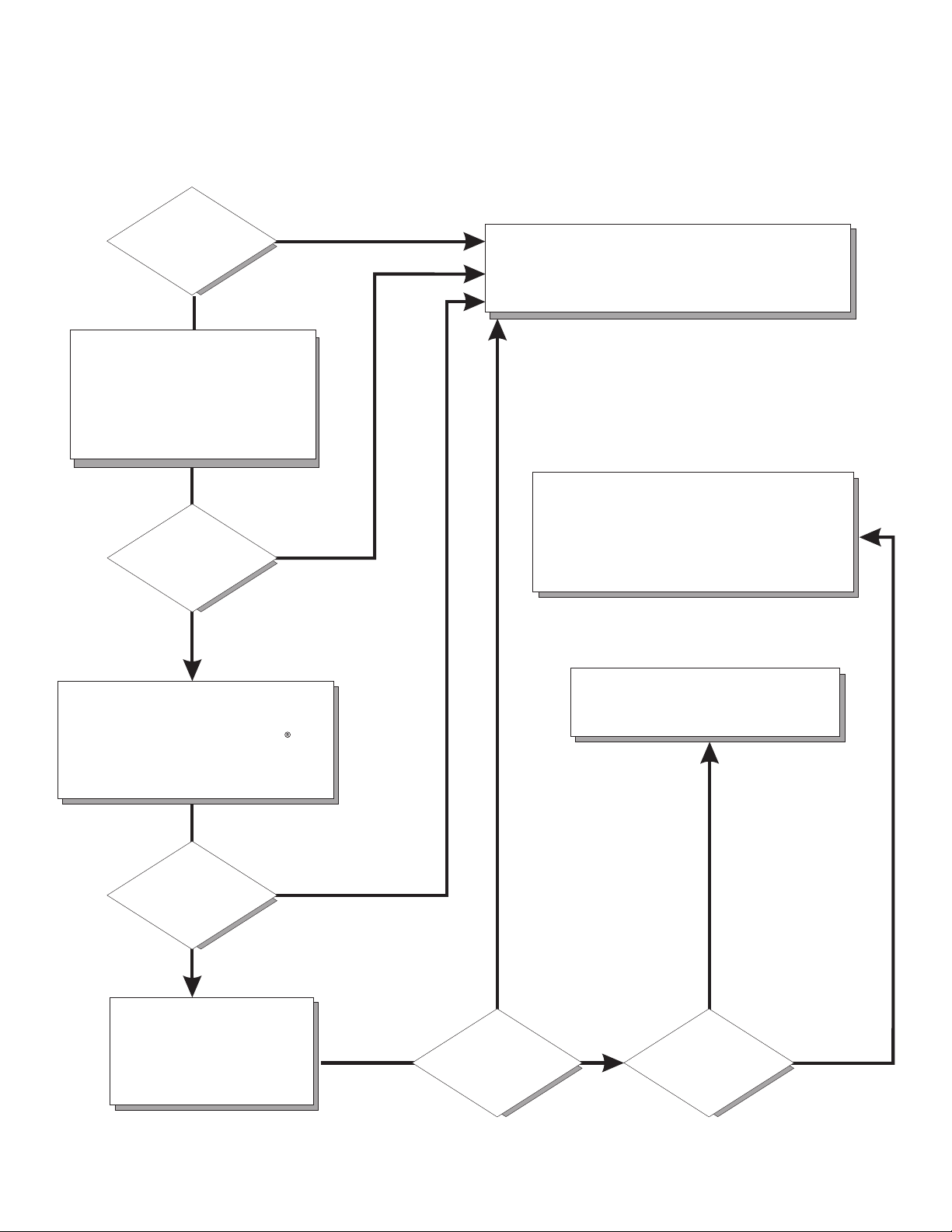
Server Support
Is the server working
correctly?
Yes
No
Update the firmware to the
latest level.
Is the problem
solved?
Yes
No
Register the server. Go to
http://www.ibm.com/support/mysupport/.
View information about IBM Support Line at
http://www.ibm.com/services/sl/products/
or view support telephone numbers at
http://www.ibm.com/planetwide/.
Check all cables for loose connections
and verify that all optional devices you
installed are on the ServerProven list at
http://www.ibm.com/servers/eserver/
serverproven/compat/us/.
Is the problem
solved?
Yes
No
See the troubleshooting
information that comes with
the server to determine
the cause of the problem
and the action to take.
Yes
Is the problem
solved?
View support telephone numbers at
http://www.ibm.com/planetwide/.
Hardware
No Software
Hardware or
software problem?
Page 3

BladeCenter QS20 Ty pe 0200
Installation an d User’s Guide
SC33-8284-02
Page 4

Note: Before using this information and the product it supports, read the general information in Appendix B, “Notices,” on page 61.
Third Edition (September 2006)
© Copyright International Business Machines Corporation 2005. All rights reserved.
US Government Users Restricted Rights – Use, duplication or disclosure restricted by GSA ADP Schedule Contract
with IBM Corp.
Page 5

Contents
Safety . . . . . . . . . . . . . . . . . . . . . . . . . . . .v
Chapter 1. Introduction . . . . . . . . . . . . . . . . . . . . . . 1
The BladeCenter QS20 . . . . . . . . . . . . . . . . . . . . . . 1
The BladeCenter . . . . . . . . . . . . . . . . . . . . . . . . .2
Power modules and power module bays . . . . . . . . . . . . . . .2
Using this book . . . . . . . . . . . . . . . . . . . . . . . . . 3
Related documentation . . . . . . . . . . . . . . . . . . . . . .4
The Documentation CD . . . . . . . . . . . . . . . . . . . . . . 5
Hardware and software requirements . . . . . . . . . . . . . . . . 5
Using the Documentation Browser . . . . . . . . . . . . . . . . .6
Notices and statements used in this document . . . . . . . . . . . . . .7
Features and specifications . . . . . . . . . . . . . . . . . . . . .7
Reliability, availability, and serviceability features . . . . . . . . . . . . . 8
Chapter 2. Blade server power, controls, and indicators . . . . . . . . . 9
Turning on the blade server . . . . . . . . . . . . . . . . . . . . . 9
Turning off the blade server . . . . . . . . . . . . . . . . . . . . 10
Blade server controls and LEDs . . . . . . . . . . . . . . . . . . . 11
System-board internal and option connectors . . . . . . . . . . . . . . 12
Chapter 3. Preparing the BladeCenter unit . . . . . . . . . . . . . . 15
Preinstallation checklist . . . . . . . . . . . . . . . . . . . . . . 15
Chapter 4. Installing the blade server in the BladeCenter unit . . . . . . 17
Installing the blade server . . . . . . . . . . . . . . . . . . . . . 17
Chapter 5. Installing and removing replaceable units . . . . . . . . .21
Installation guidelines . . . . . . . . . . . . . . . . . . . . . .21
System reliability guidelines . . . . . . . . . . . . . . . . . . .21
Handling static-sensitive devices . . . . . . . . . . . . . . . . .22
Removing the blade server from the BladeCenter unit . . . . . . . . . .23
Opening the blade server cover . . . . . . . . . . . . . . . . . . .25
Removing the blade-server bezel assembly . . . . . . . . . . . . . .27
Installing the IDE hard disk drive . . . . . . . . . . . . . . . . . .27
Installing InfiniBand . . . . . . . . . . . . . . . . . . . . . . .29
InfiniBand package content . . . . . . . . . . . . . . . . . . .29
What you need to install InfiniBand . . . . . . . . . . . . . . . . 30
Installing InfiniBand . . . . . . . . . . . . . . . . . . . . . . 30
Replacing the battery . . . . . . . . . . . . . . . . . . . . . . 37
Completing the installation . . . . . . . . . . . . . . . . . . . . .40
Installing the blade server bezel assembly . . . . . . . . . . . . . .40
Closing the blade server cover . . . . . . . . . . . . . . . . . .42
Input/output connectors and devices . . . . . . . . . . . . . . . . .43
Chapter 6. Configuring the blade server . . . . . . . . . . . . . . .45
Communicating with the blade server . . . . . . . . . . . . . . . .45
Using the command-line interface . . . . . . . . . . . . . . . . . .46
Using the serial interface . . . . . . . . . . . . . . . . . . . . .46
Starting the management and configuration program in the Management Module 47
Integrating the Gigabit Ethernet controllers into the BladeCenter . . . . . . .47
Blade server Ethernet controller enumeration . . . . . . . . . . . . . .48
Upgrading the system firmware . . . . . . . . . . . . . . . . . . .48
© Copyright IBM Corp. 2005 iii
Page 6

Firmware package and contents . . . . . . . . . . . . . . . . .49
Determining current blade server firmware code levels . . . . . . . . .49
Installing the firmware . . . . . . . . . . . . . . . . . . . . .49
Installing the firmware manually . . . . . . . . . . . . . . . . . . 50
Updating the host and service processor images . . . . . . . . . . . 50
Updating the host firmware on PERM . . . . . . . . . . . . . . . 50
Chapter 7. Installing the operating system . . . . . . . . . . . . . . 51
Chapter 8. Solving problems . . . . . . . . . . . . . . . . . . . 53
Firmware startup process . . . . . . . . . . . . . . . . . . . . . 53
Troubleshooting charts . . . . . . . . . . . . . . . . . . . . . . 54
Problems indicated by LEDs . . . . . . . . . . . . . . . . . . . 54
Power problems . . . . . . . . . . . . . . . . . . . . . . . 56
Network connection problems . . . . . . . . . . . . . . . . . . 56
Service processor problems . . . . . . . . . . . . . . . . . . . 57
Recovering the system firmware code . . . . . . . . . . . . . . . . 58
Starting the TEMP image . . . . . . . . . . . . . . . . . . . . 58
Recovering the TEMP image from the PERM image . . . . . . . . . . 58
Appendix A. Getting help and technical assistance . . . . . . . . . . 59
Before you call . . . . . . . . . . . . . . . . . . . . . . . . . 59
Using the documentation . . . . . . . . . . . . . . . . . . . . . 59
Getting help and information from the World Wide Web . . . . . . . . . . 59
Software service and support . . . . . . . . . . . . . . . . . . .60
Hardware service and support . . . . . . . . . . . . . . . . . . .60
Appendix B. Notices . . . . . . . . . . . . . . . . . . . . . .61
Edition notice . . . . . . . . . . . . . . . . . . . . . . . . .62
Trademarks . . . . . . . . . . . . . . . . . . . . . . . . . .64
Important notes . . . . . . . . . . . . . . . . . . . . . . . . .65
Product recycling and disposal . . . . . . . . . . . . . . . . . . .65
Battery return program . . . . . . . . . . . . . . . . . . . . . .66
Electronic emission notices . . . . . . . . . . . . . . . . . . . .66
Federal Communications Commission (FCC) statement . . . . . . . . .66
Industry Canada Class A emission compliance statement . . . . . . . .67
Australia and New Zealand Class A statement . . . . . . . . . . . .67
United Kingdom telecommunications safety requirement . . . . . . . . .67
Deutschsprachiger EU Hinweis: Hinweis für Geräte der Klasse A
EU-Richtlinie zur Elektromagnetischen Verträglichkeit . . . . . . . . .67
Deutschland: Einhaltung des Gesetzes über die elektromagnetische
Verträglichkeit von Geräten . . . . . . . . . . . . . . . . .68
Zulassungsbescheinigung laut dem Deutschen Gesetz über die
elektromagnetische Verträglichkeit von Geräten (EMVG) vom 18.
September 1998 (bzw. der EMC EG Richtlinie 89/336) für Geräte der
Klasse A . . . . . . . . . . . . . . . . . . . . . . . .68
European Union EMC Directive conformance statement . . . . . . . . .68
Taiwanese Class A warning statement . . . . . . . . . . . . . . .69
Japanese Voluntary Control Council for Interference (VCCI) statement . . .69
Korean Class A warning statement . . . . . . . . . . . . . . . .69
Power cords . . . . . . . . . . . . . . . . . . . . . . . . . .70
Index . . . . . . . . . . . . . . . . . . . . . . . . . . . .73
iv BladeCenter QS20 Type 0200: Installation and User’s Guide
Page 7

Safety
Before installing this product, read the Safety Information.
Antes de instalar este produto, leia as Informações de Segurança.
Pred instalací tohoto produktu si prectete prírucku bezpecnostních instrukcí.
Læs sikkerhedsforskrifterne, før du installerer dette produkt.
Lees voordat u dit product installeert eerst de veiligheidsvoorschriften.
Ennen kuin asennat tämän tuotteen, lue turvaohjeet kohdasta Safety Information.
Avant d’installer ce produit, lisez les consignes de sécurité.
Vor der Installation dieses Produkts die Sicherheitshinweise lesen.
Prima di installare questo prodotto, leggere le Informazioni sulla Sicurezza.
Les sikkerhetsinformasjonen (Safety Information) før du installerer dette produktet.
Antes de instalar este produto, leia as Informações sobre Segurança.
© Copyright IBM Corp. 2005 v
Page 8

Antes de instalar este producto, lea la información de seguridad.
Läs säkerhetsinformationen innan du installerar den här produkten.
Important:
All caution and danger statements in this documentation begin with a
number. This number is used to cross reference an English caution or
danger statement with translated versions of the caution or danger
statement in the IBM Safety Information book.
For example, if a caution statement begins with a number 1,
translations for that caution statement appear in the IBM Safety
Information book under statement 1.
Be sure to read all caution and danger statements in this
documentation before performing the instructions. Read any additional
safety information that comes with the blade server or optional device
before you install the device.
vi BladeCenter QS20 Type 0200: Installation and User’s Guide
Page 9

Statement 1:
DANGER
Electrical
current from power, telephone, and communication cables is
hazardous.
To avoid a shock hazard:
v Do not connect or disconnect any cables or perform installation,
maintenance, or reconfiguration of this product during an electrical
storm.
v Connect all power cords to a properly wired and grounded electrical
outlet.
v Connect to properly wired outlets any equipment that will be attached to
this product.
v When possible, use one hand only to connect or disconnect signal
cables.
v Never turn on any equipment when there is evidence of fire, water, or
structural damage.
v Disconnect the attached power cords, telecommunications systems,
networks, and modems before you open the device covers, unless
instructed otherwise in the installation and configuration procedures.
v Connect and disconnect cables as described in the following table when
installing, moving, or opening covers on this product or attached
devices.
To Connect: To Disconnect:
1. Turn everything OFF.
2. First, attach all cables to devices.
3. Attach signal cables to connectors.
4. Attach power cords to outlet.
1. Turn everything OFF.
2. First, remove power cords from outlet.
3. Remove signal cables from connectors.
4. Remove all cables from devices.
5. Turn device ON.
Safety vii
Page 10

Statement 2:
CAUTION:
When replacing the lithium battery, use only IBM Part Number 33F8354 or an
equivalent type battery recommended by the manufacturer. If your system has
a module containing a lithium battery, replace it only with the same module
type made by the same manufacturer. The battery contains lithium and can
explode if not properly used, handled, or disposed of.
Do not:
v Throw or immerse into water
v Heat to more than 100°C (212°F)
v Repair or disassemble
Dispose
of the battery as required by local ordinances or regulations.
viii BladeCenter QS20 Type 0200: Installation and User’s Guide
Page 11

Statement 3:
CAUTION:
When laser products (such as CD-ROMs, DVD drives, fiber optic devices, or
transmitters) are installed, note the following:
v Do not remove the covers. Removing the covers of the laser product could
result in exposure to hazardous laser radiation. There are no serviceable
parts inside the device.
v Use of controls or adjustments or performance of procedures other than
those specified herein might result in hazardous radiation exposure.
DANGER
laser products contain an embedded Class 3A or Class 3B laser
Some
diode. Note the following.
Laser radiation when open. Do not stare into the beam, do not view directly
with optical instruments, and avoid direct exposure to the beam.
Class 1 Laser Product
Laser Klasse 1
Laser Klass 1
Luokan 1 Laserlaite
Appareil A Laser de Classe 1
`
Safety ix
Page 12

Statement 4:
≥ 18 kg (39.7 lb) ≥ 32 kg (70.5 lb) ≥ 55 kg (121.2 lb)
CAUTION:
Use safe practices when lifting.
Statement 5:
CAUTION:
The power control button on the device and the power switch on the power
supply do not turn off the electrical current supplied to the device. The device
also might have more than one power cord. To remove all electrical current
from the device, ensure that all power cords are disconnected from the power
source.
2
1
x BladeCenter QS20 Type 0200: Installation and User’s Guide
Page 13

Statement 8:
CAUTION:
Never remove the cover on a power supply or any part that has the following
label attached.
Hazardous voltage, current, and energy levels are present inside any
component that has this label attached. There are no serviceable parts inside
these components. If you suspect a problem with one of these parts, contact
a service technician.
Statement 13:
DANGER
Overloading a branch circuit is potentially a fire hazard and a shock hazard
under certain conditions. To avoid these hazards, ensure that your system
electrical requirements do not exceed branch circuit protection
requirements. Refer to the information that is provided with your device for
electrical specifications.
Statement 21:
CAUTION:
Hazardous energy is present when the blade is connected to the power
source. Always replace the blade cover before installing the blade.
Safety xi
Page 14

WARNING: Handling the cord on this product or cords associated with accessories
sold with this product, will expose you to lead, a chemical known to the State of
California to cause cancer, and birth defects or other reproductive harm. Wash
hands after handling.
ADVERTENCIA: El contacto con el cable de este producto o con cables de
accesorios que se venden junto con este producto, pueden exponerle al plomo, un
elemento químico que en el estado de California de los Estados Unidos está
considerado como un causante de cancer y de defectos congénitos, además de
otros riesgos reproductivos. Lávese las manos después de usar el producto.
xii BladeCenter QS20 Type 0200: Installation and User’s Guide
Page 15

Chapter 1. Introduction
This chapter gives an overview of the processor and the BladeCenter QS20.
The BladeCenter QS20
The high performance BladeCenter QS20 is based on the 64 bit Cell Broadband
Engine
TM
processor (Cell BE) with a frequency of 3.2 GHz. Two processors are
supported per blade and are directly mounted on the blade planar board to provide
multiprocessing capability. Each processor includes 32/32 KB L1 (data/instruction)
and 512 KB L2 cache.
The Cell BE implementation of the broadband processor architecture (CBEA)
includes one PowerPC® Processor Element (PPE) core and eight synergistic
processing cores (SPE). Each SPE core includes one synergistic processing unit
(SPU) with its own local storage (LS) area, and one dedicated memory flow
controller (MFC), which has an associated memory management unit (MMU) to hold
and process memory protection and access permission information. To facilitate
data flow on-chip and externally, the Cell BE also implements the broadband engine
bus and other I/O structures.
There is a highspeed RAMBUS interface to the processor, a 4x PCI-Express
channel, a 32bit/33MHZ PCI bus interface, which is specified to attach the PATA
controller to the board, 1 Gigabit Ethernet MAC, a UART and an external bus
controller. Attached to the external bus are a Flash EPROM device (8 Mbyte), 1 MB
of battery-backed NVRAM and battery-backed RTC.
The local service processor supports environmental monitoring, front panel, chip
initialization and the Management Module interface.
To ensure compatibility with existing blades, the BladeCenter QS20 provides two
midplane connectors. These connectors contain Gigabit Ethernet links, power and a
chassis management bus. On-card VRMs generate all required voltages from the
12V bulk supply from the Blade midplane connection. The blade includes an IDE
hard disk (that can provide a boot mechanism for an operating system), and
optional BladeCenter QS20 InfiniBand 2945 Option daughter card (referred to as
InfiniBand card in this document) support. The BladeCenter QS20 operates in a
BladeCenter® (8677) chassis.
For more information about the processor, see
http://www.ibm.com/developer/power/cell.
Figure 1 on page 2 shows a BladeCenter QS20.
© Copyright IBM Corp. 2005 1
Page 16

Control-panel
door
Release
levers
InfiniBand ports
Figure 1. BladeCenter QS20
The BladeCenter QS20 is an accessory for the 8677 BladeCenter Enterprise
chassis only.
For more information about the BladeCenter QS20, see “Features and
specifications” on page 7.
The BladeCenter
The BladeCenter unit has Management Module firmware. The BladeCenter unit also
provides power, and Sense Logic Control firmware to connect processor and
support logic to the service processor.
Configuring the BladeCenter is straightforward. The basic building blocks consist of
double-width blades. You insert these blades into the IBM BladeCenter unit. Yo u
can install up to seven hot-swap BladeCenter QS20 blades in each BladeCenter
unit. Because a BladeCenter chassis is seven U high, six BladeCenter unit
completely fill a standard 42 U rack. Communication between blades within a unit
and between blades in different unit is by Ethernet. Communications with the
outside world is the same.
Power modules and power module bays
This section briefly describes power modules and power module bays.
Figure 2 on page 3 shows the location of the power module bays in the
BladeCenter Type 8677.
2 BladeCenter QS20 Type 0200: Installation and User’s Guide
Page 17

Figure 2. BladeCenter Type 8677 rear view showing the power module bays
Note: Make sure that you review and understand the design of the BladeCenter
unit. Refer to the following documents if you need help to determine your
system configuration requirements and the bays and connectors where you
install or remove components:
v The IBM Eserver BladeCenter (Type 8677) Planning and Installation
Guide on the IBM BladeCenter Documentation CD.
v http://www.ibm.com/pc/support/ on the World Wide Web.
Table 1. Power module and power module bay allocation
Minimum
number of
power
Blade server installed
in:
modules
required
Install power module in the following power
module bays:
Blade bays 1-6 One 1 (for redundancy you can install a second
power module in power module bay 2)
Blade bays 7-14 One 3 (for redundancy you can install a second
power module in power module bay 4)
Note: Do not insert a blade server in blade bays 6/7. This is because the blade
server would be split between the two sets of power modules.
Using this book
This Installation and User’s Guide provides information to help you:
v Set up the BladeCenter QS20
v Start and configure the BladeCenter QS20
v Install options
Chapter 1. Introduction 3
Page 18

v Install the operating system
v Perform basic troubleshooting of the BladeCenter QS20
Record
information about the blade server in the following table.
Product name BladeCenter QS20
Machine type 0200
Model number _____________________________________________
Serial number _____________________________________________
The machine type, model number, and serial number are on the identification label
that is behind the control-panel door on the front of the blade server, and on a label
on the side of the blade server that is visible when the blade server is not in the
BladeCenter unit. You need these numbers when you register the blade server with
IBM.
Related documentation
In addition to this document, the following documentation also comes with the
server:
v Problem Determination and Service Guide
This document is in Portable Document Format (PDF) on the IBM Documentation
CD. It contains information to help you solve problems yourself, and it contains
information for service technicians.
v Safety Information
This document is in Portable Document Format (PDF) on the IBM Documentation
CD. It contains translated caution and danger statements. Each caution and
danger statement that appears in the documentation has a number that you can
use to locate the corresponding statement in your language in the Safety
Information document.
v Warranty and Support Information
This document is in PDF on the IBM Documentation CD. It contains information
about the terms of the warranty and about service and assistance.
v BladeCenter QS20 SDK Toolkit Installation and User's Guide
This document is in PDF and can be downloaded from http://www.ibm.com/pc/
support/. It contains information about how to install the operating system and
how to program applications for the blade server.
Depending
on the server model, additional documentation might be included on the
IBM Documentation CD.
The blade server can have features that are not described in the documentation
that comes with the server. The documentation might be updated occasionally to
include information about those features, or technical updates might be available to
provide additional information that is not included in the blade server
documentation. The most recent versions of all BladeCenter documentation are at
http://www.ibm.com/bladecenter/. In addition to the documentation in this library, be
sure to review the IBM BladeCenter Planning and Installation Guide for your
BladeCenter unit type for information to help you prepare for system installation and
configuration. This document is available at http://www.ibm.com/bladecenter/.
4 BladeCenter QS20 Type 0200: Installation and User’s Guide
Page 19

The Documentation CD
The Documentation CD contains documentation for the blade server in PDF and
includes the IBM Documentation Browser to help you find information quickly.
Hardware and software requirements
The IBM BladeCenter Documentation CD requires the following minimum hardware
and software:
v Microsoft® Windows NT® 4.0 (with Service Pack 3 or later), Windows 98,
Windows 2000, Windows XP, AIX®, UNIX®, SUSE LINUX, or Red Hat Linux
v 100 MHz microprocessor
v 32 MB of RAM
v Adobe Acrobat Reader 3.0 (or later) or xpdf, which comes with Linux operating
systems
Note: Acrobat Reader software is included on the CD, and you can install it
when you run the Documentation Browser.
®
Chapter 1. Introduction 5
Page 20

Using the Documentation Browser
Use the Documentation Browser to browse the contents of the CD, read brief
descriptions of the books, and view books using Adobe Acrobat Reader or xpdf.
The Documentation Browser automatically detects the regional settings in use in
your system and displays the books in the language for that region (if available). If
a book is not available in the language for that region, the English version is
displayed.
Use one of the following procedures to start the Documentation Browser:
v If Autostart is enabled, insert the CD into your CD-ROM drive. The
Documentation Browser starts automatically.
v If Autostart is disabled or is not enabled for all users:
– If you are using a Windows operating system, insert the CD into your
CD-ROM drive and click Start Run. In the Open field, type:
x:\win32.bat
where x is the drive letter of your CD-ROM drive, then click OK.
– If you are using a Linux operating system, insert the CD into your CD-ROM
drive; then, run the following command from the /mnt/cdrom directory:
sh runlinux.sh
The Available Topics list displays all the books for the blade server. Some books
might be in folders. A plus sign (+) indicates each folder or book that has additional
books under it. Click the plus sign to display the additional books.
When you select a book, a description of the book appears under Topic
Description. To select more than one book, press and hold the Ctrl key while you
select the books. Click View Book to view the selected book or books in Acrobat
Reader or xpdf. If you selected more than one book, all the selected books are
opened in Acrobat Reader or xpdf.
To search all the books, type a word or word string in the Search field and click
Search. The books in which the word or word string appears are listed in order of
the most occurrences. Click a book to view it, and press Crtl+F to use the Acrobat
search function or Alt+F to use the xpdf search function within the book.
Click Help for detailed information about using the Documentation Browser.
6 BladeCenter QS20 Type 0200: Installation and User’s Guide
Page 21

Notices and statements used in this document
The caution and danger statements that appear in this document are also in the
multilingual Safety Information document, which is on the IBM BladeCenter
Documentation CD. Each statement is numbered for reference to the corresponding
statement in the Safety Information document.
The following notices and statements are used in this document:
v Notes: These notices provide important tips, guidance, or advice.
v Important: These notices provide information or advice that might help you avoid
inconvenient or problem situations.
v Attention: These notices indicate potential damage to programs, devices, or
data. An attention notice is placed just before the instruction or situation in which
damage could occur.
v Caution: These statements indicate situations that can be potentially hazardous
to you. A caution statement is placed just before the description of a potentially
hazardous procedure step or situation.
v Danger: These statements indicate situations that can be potentially lethal or
extremely hazardous to you. A danger statement is placed just before the
description of a potentially lethal or extremely hazardous procedure step or
situation.
Features and specifications
The following table provides a summary of the features and specifications of the
BladeCenter QS20.
Through the BladeCenter Management Module, you can view the blade server
firmware code and other hardware configuration information.
The BladeCenter QS20 does not support the function of any USB ports, optical
drives, or floppy drives native to the BladeCenter.
The BladeCenter QS20 InfiniBand option only supports the IP-over-IB protocol.
The BladeCenter QS20 is an accessory for the 8677 BladeCenter Enterprise
chassis only.
Note: Power, cooling, removable-media drives, external ports, and advanced
system management are provided by the IBM BladeCenter Type 8677. For
more information, see the IBM BladeCenter (Type 8677) Planning and
Installation Guide.
Chapter 1. Introduction 7
Page 22

Table 2. Blade server features and specifications
Microprocessor:
Two IBM Cell Broadband Engines
PowerPC 64-bit architecture w/VMX
with 8 SPUs, 512 KB L2 cache, 256
KB on each SPE.
Memory:2 x 256 MB or 2 x 512 MB
XDR DRAM with ECC. (Only
configuration supported.)
IDE device: Support for one internal
integrated drive electronics (IDE)
2.5-inch hard disk drive.
Size:
v Height: 24.5 cm (9.7 inches)
v Depth: 44.6 cm (17.6 inches)
v Width: 5.8 cm (2.28 inches)
v Maximum weight: 6 kg (13.2 lb)
Integrated
functions:
v Two 1 Gigabit Ethernet controllers
v Local service processor
v One IDE hard disk drive controller
with one channel
v RS-485 interface for
Environment:
v Air temperature:
v
Humidity:
communication with BladeCenter
Management Module
Electrical
v Power supply: 12 V DC
Reliability, availability, and serviceability features
Three important features in server design are reliability, availability, and
serviceability (RAS). These RAS features are designed to help you protect the
integrity of the data stored on your blade server; help ensure that your blade server
is available when you want to use it; and, in the event of a failure, help you easily
diagnose and repair the failure with minimal inconvenience.
– Operating temperature: maximum
25°C (77°F). Altitude: 0 to 914 m
(0 to 3000 ft)
– Operating temperature: maximum
25°C (77°F). Altitude: 914 m to
2133 m (3000 ft to 7000 ft)
– Storage temperature: -40° to
60°C (–40° to 140° F)
– Operating temperature: 8% to
80%
– Storage temperature: 5% to 80%
input:
The following is a list of some of the RAS features that your blade server supports:
v Automatic error retry or recovery
v Automatic server restart
v Built-in monitoring for temperature, voltage, and hard disk drives
v Customer-upgradeable system firmware code
v Diagnostic support of Ethernet controller ports
v Error codes and messages
v Error correcting code (ECC) protection on the Level 2 (L2) cache
v ECC memory
v Service processor that communicates with the BladeCenter Management Module
to enable remote blade server management
v SDRAM with serial presence detect (SPD) and vital product data (VPD)
v System error logging
v VPD (includes information stored in nonvolatile memory for easier remote
viewing)
8 BladeCenter QS20 Type 0200: Installation and User’s Guide
Page 23

Chapter 2. Blade server power, controls, and indicators
This chapter describes the power features, how to turn on and turn off the blade
server, and what the controls and indicators mean.
Turning on the blade server
Notes:
v After you have installed the BladeCenter QS20, wait until the power-on LED on
the blade server flashes slowly before pressing the blade server power-control
button. Before the LED flashes, the service processor in the BladeCenter
Management Module is initializing, and the power-control button on the blade
server will not respond.
v While the blade server is powering up, the power-on LED on the front of the
server is lit. See “Blade server controls and LEDs” on page 11 for the power-on
LED states.
v Throughout this document, the Management Module Web-based user interface is
also known as the BladeCenter Management Module Web interface.
you have installed the BladeCenter QS20, the blade server can start in any of
After
the following ways:
v You can press the power-control button on the front of the blade server (behind
the control-panel door) to start the server.
v If a power failure occurs, the BladeCenter unit and then the blade server can
start automatically when power is restored (if the blade server is configured
through the BladeCenter Management Module to do so).
v You can use the BladeCenter Management Module Web interface to turn on the
blade server remotely.
© Copyright IBM Corp. 2005 9
Page 24

Turning off the blade server
When you turn off the blade server, it is still connected to power through the
BladeCenter unit. The blade server can respond to requests from the service
processor, such as a remote request to turn on the blade server.
To avoid loss of data, shut down the Linux operating system before you turn off the
blade server. Shut down the operating system by typing the shutdown -h now
command. See your operating-system documentation for additional information
about shutting down the operating system.
If the blade server has not been turned off, the blade server can be turned off in
any of the following ways:
v You can press the power-control button on the blade server (behind the
control-panel door). This starts an orderly shutdown of the operating system, if
this feature is supported by your operating system.
Note: After turning off the blade server, wait at least 5 seconds before you press
the power-control button to turn on the blade server again.
v If the operating system stops functioning, you can press and hold the
power-control button for more than 4 seconds to turn off the blade server.
v You can use the BladeCenter Management Module Web interface to turn on the
blade server remotely.
After you have turned off the blade server, wait at least 30 seconds for the
Note:
hard disk drives to stop spinning before you remove the blade server from
the BladeCenter unit.
10 BladeCenter QS20 Type 0200: Installation and User’s Guide
Page 25

Blade server controls and LEDs
This section describes the controls and LEDs on the blade server.
Power-control button: This button is behind the control-panel door. Press this
button to manually turn the blade server on or off.
Note: The power-control button has effect only if local power control is enabled for
the blade server. Local power control is enabled and disabled through the
BladeCenter Management Module Web interface.
Figure 3. Power-control button
Chapter 2. Blade server power, controls, and indicators 11
Page 26

Notes:
v The control-panel door is shown in the closed (normal) position in this illustration.
v The blade-error LED, information LED, and location LED can be turned off
through the BladeCenter Management Module Web interface.
v For additional information about errors, see “Problems indicated by LEDs” on
page 54.
v This blade server does not have a keyboard/mouse/video select button.
Blade-error
LED
Information
LED
Location
LED
Activity
LED
Power-on
LED
CD
Figure 4. Controls and LEDs
Blade-error LED: When this amber LED is lit, it indicates that a system error has
occurred in the blade server.
Information LED: Not supported.
Location LED: When this blue LED is lit, it has been turned on remotely by the
system administrator to aid in visually locating the blade server. The location LED
on the BladeCenter unit will be lit also.
Activity LED: When this green LED is lit, it indicates that there is network activity.
Power-on LED: This green LED indicates the power status of the blade server in
the following manner:
v Flashing rapidly - The service processor on the blade server is communicating
with the BladeCenter Management Module.
v Flashing slowly - The blade server has ac power but is not turned on.
v Lit continuously (steady) - The blade server has ac power and is turned on.
v Not lit. Power failure occurred on the blade server
System-board internal and option connectors
The following illustration shows the location of the system-board components,
including connectors for user-installable options.
Note: The illustrations in this document might differ slightly from your hardware.
12 BladeCenter QS20 Type 0200: Installation and User’s Guide
Page 27

PCI-Express
(J14)
Battery (BH1)
(J15)
PCI expansion slot
Figure 5. System board components
Microprocessor 1
and heat sink (U31)
Microprocessor 0
and heat sink (U1)
Control panel
connector (J9)
Chapter 2. Blade server power, controls, and indicators 13
Page 28

14 BladeCenter QS20 Type 0200: Installation and User’s Guide
Page 29

Chapter 3. Preparin g the BladeCenter unit
This chapter describes the tasks that you must perform before you can use the
BladeCenter unit with the blade server.
Preinstallation checklist
Before you can use the BladeCenter unit with the blade server, you must correctly
set up and configure the BladeCenter unit, and install and configure the required
components in the BladeCenter unit. If you have not already done so, perform the
activities on the following checklist:
__ 1. Set up the rack in which you will install the BladeCenter unit.
__ 2. Install the BladeCenter unit in a rack.
__ 3. Install and configure the required BladeCenter unit components:
__ a. Make sure that the BladeCenter unit has adequate power to support
all the installed devices. The BladeCenter unit must contain either two
or four power modules. If necessary, upgrade the power modules in
the BladeCenter unit. For additional information, see the IBM
BladeCenter Power Module Upgrade Guidelines.
__ b. Install and configure one or two Management Modules in the
BladeCenter unit. For the BladeCenter QS20, BladeCenter 8677 with
Management Module 1 is the only supported chassis.
__ c. Install and configure one or two Gigabit Ethernet modules in the
BladeCenter unit. For the BladeCenter QS20 only the following
BladeCenter Ethernet switch-modules are supported:
v Nortel Networks Layer 2/3 Copper Gigabit Ethernet Switch Module
(P/N: 26K6530)
v Cisco Systems Intelligent Gigabit Ethernet Switch Module (P/N:
13N2281 / 32R1892 / FRU 13N2285)
Cisco Ethernet switch-modules need a special configuration
Note:
to work properly with a BladeCenter QS20.
4. If the BladeCenter unit was shipped to you before June 2003, make sure
__
that:
__ a. The hardware and firmware in the BladeCenter unit are at the
supported levels for the blade server. Go to the IBM Support Web
site, http://www.ibm.com/pc/support/, for additional information.
__ b. The BladeCenter unit has the correct customer interface card (CIC).
For illustrations and additional information, see the following related documentation
on the World Wide Web at http://www.ibm.com/pc/support/:
v IBM BladeCenter (Type 8677) Planning and Installation Guide
v IBM BladeCenter Power Module Upgrade Guidelines
v IBM BladeCenter Management Module Installation Guide
v IBM BladeCenter Management Module Command-Line Interface Reference
Guide
v The documentation that comes with the Ethernet switch module that you are
using; for example:
– IBM BladeCenter Cisco Systems Intelligent Gigabit Ethernet Switch Module
Installation Guide
© Copyright IBM Corp. 2005 15
Page 30

– IBM BladeCenter Nortel Networks Layer 2/3 GbE Switch Module Installation
Guide
For more information, see “Related documentation” on page 4.
Note:
16 BladeCenter QS20 Type 0200: Installation and User’s Guide
Page 31

Chapter 4. Installin g the blade server in the BladeCenter unit
If you have options to install in the blade server, refer to the BladeCenter QS20
Problem Determination and Service Guide for instructions; then, return here.
Otherwise, continue with the instructions in this chapter.
Installing the blade server
Figure 6. Inserting the blade server into the BladeCenter
Notes:
v For information about the design of the BladeCenter unit, including the hot-swap
blade bays, see the IBM BladeCenter (Type 8677) Planning and Installation
Guide.
v The blade server is a hot-swap device. Yo u can install or remove the blade
server without removing power from the BladeCenter unit. However, you must
turn off the blade server before removing it from the BladeCenter unit.
v The maximum number of blade servers that the BladeCenter unit supports varies
by the wattage of the power supplies that are installed in the BladeCenter unit.
For more information about determining the power requirements for the blade
server, see the IBM BladeCenter Power Module Upgrade Guidelines.
v Do not install a blade server in blade bays 6/7. For more information and
explanation, see Table 1 on page 3.
v To help ensure proper cooling, performance, and system reliability, do not
operate the BladeCenter unit for more than 1 minute without a blade server or
filler blades installed in each blade bay.
When you remove filler blades from a blade bay in the BladeCenter unit so that
you can install a blade server, do not discard the filler blades. Yo u need the filler
blades if you ever remove the blade server. For future use, store the filler blades
in a static-protective environment, such as the static-protective package that
comes with the blade server.
© Copyright IBM Corp. 2005 17
Page 32

Attention: If you plan to remove a blade server and reinstall it, be sure to note
the number of the bay that contains the blade server before you remove it. Then,
reinstall the blade server in the same bay from which it was removed. Reinstalling a
blade server into a different bay than the one from which it was removed could
have unintended consequences, such as incorrectly reconfiguring the blade server.
Some blade server configuration information and update options are established
according to bay number. If you reinstall the blade server into a different bay, you
might have to reconfigure the blade server.
Statement 21:
CAUTION:
Hazardous energy is present when the blade server is connected to the power
source. Always replace the blade cover before installing the blade server.
Complete the following steps to install a blade server into the BladeCenter unit:
1. Read the safety information beginning on page v and “Installation guidelines”
on page 21.
2. If you have not done so already, install any options needed, such as disk
drives or memory, in the blade server.
3. Select the bay for the blade server.
4. If the bay that you selected contains filler blades, remove the filler blades. For
future use, store the filler blades in a static-protective environment.
5. Make sure that the release levers on the blade server are in the open position
(perpendicular to the blade server).
6. Slide the blade server into the bay until it stops. The spring-loaded doors
further back in the bay that cover the bay opening move out of the way as you
insert the blade server.
7. Push the release levers on the front of the blade server to the closed position.
8. (Optional) A set of user labels comes with the blade server. Write identifying
information on one of the user labels for the blade server; then, place the label
on the BladeCenter unit bezel just below the blade server, as shown in
Figure 7 on page 19.
If you install a blade server in bay 13-14, place the label next to the product
name. Do not cover the label that contains the system information.
18 BladeCenter QS20 Type 0200: Installation and User’s Guide
Page 33

Attach here
Figure 7. Where to attach user labels
Important: Do not place the label on the blade server or in any way block the
ventilation holes on the blade server.
9. If this is not the initial installation of this blade server in the BladeCenter unit,
continue with the next step.
If this is the initial installation of this blade server in the BladeCenter unit, you
must perform the following additional tasks:
a. Turn on the blade server by pressing the power-control button on the blade
server control panel. The power-on LED on the blade server changes from
the slowly-flashing state to a continuously lit (steady) state.
b. Install the operating system. Use the installation instructions that come with
the operating system. For more information, see Chapter 7, “Installing the
operating system,” on page 51.
If you have already installed the operating system on the blade server, the
10.
blade server is ready to use.
If you have not already done so, turn on the blade server by pressing the
power-control button on the blade server control panel. The power-on LED on
the blade server changes from the slowly-flashing state to a continuously lit
(steady) state.
11. If you have other blade servers to install, you can do so now.
Chapter 4. Installing the blade server in the BladeCenter unit 19
Page 34

20 BladeCenter QS20 Type 0200: Installation and User’s Guide
Page 35

Chapter 5. Installin g and removing replaceable units
This chapter provides instructions for replacing units on the blade server.
Replaceable units are components, such as memory modules, the hard disk drive,
and I/O expansion cards. (Some removal instructions are provided in case you
need to remove one replaceable unit to install another.)
The following replaceable units are supported:
v Battery
v IDE hard disk (one only)
v The bezel assembly (control panel)
v InfiniBand cards (optional)
Installation guidelines
Before you begin, read the following information:
v Read the safety information beginning on page v and the guidelines in “Handling
static-sensitive devices” on page 22. This information will help you work safely
with the blade server and options.
v Read the information in .
v Back up all important data before you make changes to disk drives.
v Have a small flat-blade screwdriver and a Phillips screwdriver available.
v You do not have to turn off the blade server or disconnect the BladeCenter unit
from power to install or replace any of the hot-swap modules on the rear of the
BladeCenter unit.
v Before you remove a hot-swap blade server from the BladeCenter unit, you must
shut down the operating system by typing the shutdown -h now command. If the
blade server was not turned off, press the power-control button (behind the
blade-server control-panel door) to turn off the blade server. You do not have to
shut down the BladeCenter unit itself.
v Blue on a component indicates touch points, where you can grip the component
to remove it from or install it in the blade server or BladeCenter unit, open or
close a latch, and so on.
v Orange on a component or an orange label on or near a component indicates
that the component can be hot-swapped, which means that if the blade server or
BladeCenter unit and operating system support hot-swap capability, you can
remove or install the component while the blade server or BladeCenter unit is
running. (Orange can also indicate touch points on hot-swap components.) See
the instructions for removing or installing a specific hot-swap component for any
additional procedures that you might have to perform before you remove or
install the component.
System reliability guidelines
To help ensure proper cooling and system reliability, make sure that:
v The ventilation holes on the blade server are not blocked.
v Each of the blade bays on the front of the BladeCenter unit has a blade server or
filler blade installed. Do not operate the BladeCenter unit for more than 1 minute
without a blade server or filler blade installed in each blade bay.
v You have followed the reliability guidelines in the documentation that comes with
the BladeCenter unit.
© Copyright IBM Corp. 2005 21
Page 36

v You have not installed any small computer system interface (SCSI) devices. The
blade server does not support SCSI devices. If you attach SCSI devices to the
blade server, these devices will not be recognized or configured, and they will not
operate.
Handling static-sensitive devices
Attention: Static electricity can damage electronic devices and your system. To
avoid damage, keep static-sensitive devices in their static-protective packages until
you are ready to install them.
To reduce the possibility of electrostatic discharge, observe the following
precautions:
v Limit your movement. Movement can cause static electricity to build up around
you.
v Handle the device carefully, holding it by its edges or its frame.
v Do not touch solder joints, pins, or exposed printed circuitry.
v Do not leave the device where others can handle and damage it.
v While the device is still in its static-protective package, touch it to an unpainted
metal part of the BladeCenter chassis for at least 2 seconds. This drains static
electricity from the package and from your body.
v Remove the device from its package and install it directly into the blade server or
BladeCenter unit without setting the device down. If it is necessary to set down
the device, put it back into its static-protective package. Do not place the device
on the blade server cover or on a metal surface.
v Take additional care when handling devices during cold weather. Heating reduces
indoor humidity and increases static electricity.
v Wear an electrostatic-discharge wrist strap, if one is available.
22 BladeCenter QS20 Type 0200: Installation and User’s Guide
Page 37

Removing the blade server from the BladeCenter unit
The following illustration shows how to remove the blade server from the
BladeCenter unit.
Figure 8. Removing the blade server
Attention:
v To maintain proper system cooling, do not operate the BladeCenter unit for more
than 1 minute without a blade server or filler blades installed in each blade bay.
v Note the number of the bay that contains the blade server that you remove. Yo u
need this information if you decide to reinstall the blade server in the
BladeCenter unit. If you reinstall the blade server, be sure to reinstall it in the
same bay from which it was removed. Reinstalling a blade server into a different
bay than the one from which it was removed could have unintended
consequences, such as incorrectly reconfiguring the blade server. Some blade
server configuration information and update options are established according to
bay number. If you reinstall the blade server into a different bay, you might have
to reconfigure the blade server.
The blade server is a hot-swap device, and the blade bays in the
Note:
BladeCenter unit are hot-swap bays. Therefore, you can install or remove
the blade server without removing power from the BladeCenter unit.
However, you must turn off the blade server before removing it from the
BladeCenter unit.
Complete the following steps to remove the blade server:
1. Read the safety information beginning on page v and “Installation guidelines” on
page 21.
2. If the blade server is operating, the power-on LED is lit continuously (steady).
Shut down the operating system by typing the shutdown -h now command. If the
blade server was not turned off, press the power-control button (behind the
blade-server control-panel door) to turn off the blade server. See “Blade server
controls and LEDs” on page 11 for more information about the location of the
power-control button.
Attention: Wait at least 30 seconds for the hard disk drives to stop spinning,
before proceeding to the next step.
3. Open the two release levers as shown in the illustration. The blade server
moves out of the bay approximately 0.6 cm (0.25 inch).
Chapter 5. Installing and removing replaceable units 23
Page 38

4. Pull the blade server out of the bay.
5. Place either a filler blade or a new blade server in the bay within 1 minute.
24 BladeCenter QS20 Type 0200: Installation and User’s Guide
Page 39

Opening the blade server cover
The following illustration shows how to open the cover on the blade server. The
BladeCenter QS20 has an inner cover as well as an outer cover.
1. Open outer cover
Outer cover release
2. Remove outer cover from blade server
3. Remove second power board
4. Open inner cover
and front bezel
Second power board
Front bezel release
Front bezel
Inner cover release
Figure 9. Opening the blade server cover
Complete the following steps to open the blade server cover:
1. Read the safety information beginning on page v and “Installation guidelines” on
page 21.
2. Carefully place the blade server on a flat, static-protective surface, with the
cover side up.
3. Press the blue blade-cover release on each side of the blade server and lift the
outer cover open (see Figure 9, step 1).
4. Lift the cover from the blade server and set it aside (see Figure 9, step 2).
5. Remove the second power board (see Figure 9, step 3).
6. Disconnect any (optionally) installed PCI-Express cables.
7. Press the two front bezel release buttons on each side of the server and
remove the front bezel assembly (see Figure 10 on page 27 and Figure 9, step
3).
8. Press the blue blade-cover release on each side of the blade server and lift the
inner cover open (see Figure 9, step 4).
Chapter 5. Installing and removing replaceable units 25
Page 40

Statement 21:
CAUTION:
Hazardous energy is present when the blade server is connected to the power
source. Always replace the blade cover before installing the blade server.
26 BladeCenter QS20 Type 0200: Installation and User’s Guide
Page 41

Removing the blade-server bezel assembly
Before you can replace a defective system-board assembly or blade-server bezel
assembly, you must first remove the blade-server bezel assembly. The following
illustration shows how to remove the bezel assembly from a blade server.
Bezel release buttons
Bezel release buttons
Control panel
connector
Control panel
cable
Serial
connector
Serial
cable
Front bezel
Figure 10. Removing the bezel assembly
Complete the following steps to remove the blade-server bezel assembly:
1. Read the safety information beginning on page v and “Installation guidelines” on
page 21.
2. Open the blade server cover.
3. Press the bezel-assembly release and pull the bezel assembly away from the
blade server approximately 1.2 cm (0.5 inch).
4. Disconnect the control panel cable from the control panel connector.
5. Disconnect the serial cable from the serial connector.
6. Pull the bezel assembly away from the blade server.
7. Store the bezel assembly in a safe place.
Installing the IDE hard disk drive
The blade server has a connector on the system board for installing a 2.5-inch
integrated drive electronics (IDE) hard disk drive. The BladeCenter QS20 model
comes with the IDE hard disk drive already installed.
Note: Some hard disk drives have Phillips screws; therefore, make sure that a
Phillips screwdriver is available.
Attention: To maintain proper system cooling, do not operate the BladeCenter
unit for more than 1 minute without a blade server or filler blade installed in each
blade bay.
Chapter 5. Installing and removing replaceable units 27
Page 42

1. Install the hard disk into the blade server
PCI ATA Controller
Cable connected to
hard disk
Tray
Cable connected to
PCI ATA Controller
IDE Drive
2. Hard disk and PCI ATA controller installed on the
blade server system board
PCI ATA controller
Cable connected to
PCI ATA controller
Cable connected to
hard disk
Hard disk
Figure 11. Installing the hard disk
Attention:
v Do not press on the top of the hard disk drive when installing it. Pressing the top
could damage the hard disk drive.
v IDE hard disk drives must be set to master.
Complete
1. Read the safety information beginning on page v and “Installation guidelines”
the following steps to install a 2.5-inch IDE hard disk drive:
on page 21.
2. If the blade server is operating, shut down the Linux operating system by
typing the shutdown -h now command. If the blade server was not turned off,
press the power-control button (behind the blade-server control-panel door) to
turn off the blade server. See “Blade server controls and LEDs” on page 11 for
more information about the location of the power-control button.
3. Remove the blade server from the BladeCenter unit. (See “Removing the
blade server from the BladeCenter unit” on page 23 for instructions.) Carefully
place the blade server on a flat, static-protective surface.
4. Open the blade server cover. See “Opening the blade server cover” on page
25 for instructions.
5. Place the tray from the option kit on the system board, aligning the tray with
the screws on the system board. Note the four screws that are under the four
screw holes in the tray. Set the tray aside and remove the four screws.
6. Replace the tray and secure the tray to the system board with screws from the
hardware kit.
7. Connect the cable to the PCI ATA controller at one end and the hard disk drive
at the other end.
8. Insert the PCI ATA controller card into the slot on the system board
9. Place the hard disk drive into the tray and, from the rear edge of the hard disk
drive, push it into the tray. The hard disk drive clicks into place.
10. If you have other options to install or remove, do so now; otherwise, go to
“Completing the installation” on page 40.
28 BladeCenter QS20 Type 0200: Installation and User’s Guide
Page 43

Installing InfiniBand
This section describes how to install the InfiniBand option.
Notes:
1. The QS20 InfiniBand card requires the replacement of the front bezel to meet
EMC standards. The new bezel comes with the QS20 InfiniBand card and
should replace the original as part of the installation process.
2. Before installing any InfiniBand option make sure you have the operating
system (Fedora Core 5) and a patched kernel supporting BladeCenter QS20
with InfiniBand installed otherwise the blade will hang during the initial reboot
after the OS installation.
3. If your BladeCenter QS20 comes with InfiniBand option(s) already installed,
unplug the PCI-Express cable(s) on the board side or uninstall the InfiniBand
option(s), then install the OS and the patched kernel, and finally refit the
PCI-Express cable(s) or re-install the InfiniBand option(s).
InfiniBand package content
Each InfiniBand
TM
option package consists of:
Table 3. InfiniBand package contents
Description What the item looks like
1 x Mellanox InfiniBand
card
1 x adapter card
1 x PCI-Express cable
Chapter 5. Installing and removing replaceable units 29
Page 44

Table 3. InfiniBand package contents (continued)
Description What the item looks like
1 x blade bezel
4 x screws
1 x gasket
What you need to install InfiniBand
Make sure you have a small flat screwdriver before you install your InfiniBand card.
Installing InfiniBand
To install an InfiniBand option, do the following:
1. Shut down the BladeCenter QS20.
2. Remove the BladeCenter QS20 from BladeCenter.
3. Open the top cover.
4. Unlatch the front bezel and partially remove it from the metal guides.
5. Unplug the control panel and serial cable connectors from the blade’s board as
shown in Figure 12 on page 31.
30 BladeCenter QS20 Type 0200: Installation and User’s Guide
Page 45

Figure 12. Unplugging the control panel and serial cable connectors
6. Set the bezel aside.
7. Plug the InfiniBand card into the PCIe Express adapter card. Make sure the
index hole of the InfiniBand card matches the index mark of the adapter, see
Figure 13 on page 32.
Chapter 5. Installing and removing replaceable units 31
Page 46

Figure 13. InfiniBand card connected to PCI Express adapter card
8. Mount this assembly into the BladeCenter QS20 so that the InfiniBand ports of
the InfiniBand card point to the front bezel and match the respective ports of
the front bezel.
9. Secure the assembly with the four screws that were delivered with your
InfiniBand card, see Figure 14 on page 33.
32 BladeCenter QS20 Type 0200: Installation and User’s Guide
Page 47

Figure 14. Mounting point and position description
10. Optional: repeat the above steps for the second InfiniBand option.
11. Prepare the new front bezel by attaching the control panel and serial cable
connectors onto the blade’s board.
12. Partially insert the side fins of the bezel into the metal guides while ensuring
that the top of the bezel rests on the foam gasket on the InfiniBand card as
shown in Figure 15 on page 34.
Make sure the serial cable, routed along the inside and across the
Note:
bottom of the bezel, is housed underneath the blade’s board
13. After you have checked the routing, fully latch the bezel to the blade.
Chapter 5. Installing and removing replaceable units 33
Page 48

Figure 15. Refitting the bezel to the blade
14. Remove the small metal cover on the front bezel from the slot where the
InfiniBand option was installed.
Figure 16. Removing the InfiniBand slot cover
Note: If only one InfiniBand option is to be installed, it is recommended that
you install it in the upper slot.
15. Plug the PCI-Express cable into the BladeCenter QS20's PCI-Express
connector closest to the InfiniBand card. Leave the other end unconnected.
34 BladeCenter QS20 Type 0200: Installation and User’s Guide
Page 49

Note: The cable is assymetric! Yo u must plug the connector with two clamps
into the BladeCenter QS20 and the connector with only one clamp into
the adaptor card (with the clamp facing you), see Figure 17.
16. Fan out the cables and carefully bend them sidewards.
17. Connect the second connector of the PCI-Express cable to the InfiniBand card
adaptor. If you have installed the lower (second) InfiniBand option, be careful
not to damage the second card when you install the connector to the upper
card.
Figure 17. PCI Express connector installation (if you have installed the second InfiniBand
option)
18. Optional: repeat the above steps for the second InfiniBand option.
Note: When you install the lower (second) InfiniBand option, make sure that
the PCI-Express cable is not blocking the top cover.
19. Peel the back of the 8.75 inch gasket to expose the adhesive. Apply the
gasket to the QS20 cover as shown in the figure below. The gasket is applied
on the inside of the cover so that it rests on the edge of the front bezel.
Chapter 5. Installing and removing replaceable units 35
Page 50

Figure 18. Cover with gasket
20. Carefully close the cover.
36 BladeCenter QS20 Type 0200: Installation and User’s Guide
Page 51

Replacing the battery
IBM has designed this product with your safety in mind. The lithium battery must be
handled correctly to avoid possible danger. If you replace the battery, you must
adhere to the following instructions.
Note: In the U. S., call 1-800-IBM-4333 for information about battery disposal.
If you replace the original lithium battery with a heavy-metal battery or a battery with
heavy-metal components, be aware of the following environmental consideration.
Batteries and accumulators that contain heavy metals must not be disposed of with
normal domestic waste. They will be taken back free of charge by the manufacturer,
distributor, or representative, to be recycled or disposed of in a proper manner.
To order replacement batteries, call 1-800-IBM-SERV within the United States, and
1-800-465-7999 or 1-800-465-6666 within Canada. Outside the U.S. and Canada,
call your IBM authorized reseller or IBM marketing representative.
Note: After you replace the battery, the blade server is automatically reconfigured;
however, you must reset the system date and time through the operating
system that you installed.
Statement 2:
CAUTION:
When replacing the lithium battery, use only IBM Part Number 33F8354 or
15F8409 or an equivalent type battery recommended by the manufacturer. If
your system has a module containing a lithium battery, replace it only with
the same module type made by the same manufacturer. The battery contains
lithium and can explode if not properly used, handled, or disposed of.
Do not:
v Throw or immerse into water
v Heat to more than 100°C (212°F)
v Repair or disassemble
Dispose
of the battery as required by local ordinances or regulations.
Note: See “Battery return program” on page 66 for more information about battery
disposal.
Complete the following steps to replace the battery:
1. Read the safety information beginning on page v and “Installation guidelines”
on page 21.
2. Follow any special handling and installation instructions that come with the
battery.
3. If the blade server is operating, shut down the operating system by typing the
shutdown -h now command. If the blade server was not turned off, press the
power-control button (behind the blade-server control-panel door) to turn off
Chapter 5. Installing and removing replaceable units 37
Page 52

the blade server. See “Blade server controls and LEDs” on page 11 for more
information about the location of the power-control button.
4. Remove the blade server from the BladeCenter unit (see “Removing the blade
server from the BladeCenter unit” on page 23 for information).
5. Carefully place the blade server on a flat, static-protective surface.
6. Open the blade server cover (see “Opening the blade server cover” on page
25 for instructions).
7. Locate the battery (connector BH1) on the system board.
Battery (BH1)
Figure 19. Battery location
8. Remove the battery:
a. Use your finger to press down on one side of the battery; then, slide the
battery out from its socket. The spring mechanism will push the battery out
toward you as you slide it from the socket.
Note: Yo u might need to lift the battery clip slightly with your fingernail to
make it easier to slide the battery.
b. Use your thumb and index finger to pull the battery from under the battery
clip.
Note: After you remove the battery, press gently on the clip to make sure
that the battery clip is touching the base of the battery socket.
9. Insert the new battery:
a. Tilt the battery so that you can insert it into the socket, under the battery
clip. Make sure that the side with the positive (+) symbol is facing up.
b. As you slide it under the battery clip, press the battery down into the
socket.
38 BladeCenter QS20 Type 0200: Installation and User’s Guide
Page 53

10. Close the blade server cover (see “Closing the blade server cover” on page
42).
Statement 21:
CAUTION:
Hazardous energy is present when the blade server is connected to the
power source. Always replace the blade cover before installing the blade
server.
11. Reinstall the blade server into the BladeCenter unit .
12. Turn on the blade server (see “Turning on the blade server” on page 9).
13. Reset the system date and time through the operating system that you
installed. For additional information, see your operating-system documentation.
Chapter 5. Installing and removing replaceable units 39
Page 54

Completing the installation
To complete the installation, perform the following tasks, if you have not already
done so.
1. Install the blade-server bezel assembly on the blade server (see “Installing the
blade server bezel assembly”).
2. Close the blade server cover (see “Closing the blade server cover” on page 42).
Statement 21:
CAUTION:
Hazardous energy is present when the blade server is connected to the
power source. Always replace the blade cover before installing the blade
server.
3. Reinstall the blade server into the BladeCenter unit .
4. Turn on the blade server (see “Turning on the blade server” on page 9).
5. After you replace the battery or the system-board assembly, reset the system
date and time through the operating system that you installed. For additional
information, see your operating-system documentation.
If you have just connected the power cords of the BladeCenter unit to
Note:
electrical outlets, you will have to wait until the power-on LED on the blade
server flashes slowly before pressing the power-control button on a blade
server.
Installing the blade server bezel assembly
The following illustration shows how to install the bezel assembly on the blade
server.
Bezel release buttons
Bezel release buttons
Serial
connector
Serial
cable
Control panel
connector
Control panel
cable
Figure 20. Installing the bezel assembly
Complete the following steps to install the blade-server bezel assembly:
40 BladeCenter QS20 Type 0200: Installation and User’s Guide
Front bezel
Page 55

1. Read the safety information beginning on page v and “Installation guidelines” on
page 21.
2. Connect the control-panel cable to the control-panel connector on the
system-board assembly.
3. Connect the serial cable from the serial connector to the serial connector on the
system-board assembly.
4. Carefully slide the bezel assembly onto the blade server as shown in the
illustration, until it clicks into place.
Note:
v If InfiniBand is installed, partially insert the side fins of the bezel into the
metal guides while ensuring that the top of the bezel rests on the foam
gasket on the InfiniBand card.
v Make sure the serial cable, routed along the inside and across the bottom
of the bezel, is housed underneath the blade’s board.
Chapter 5. Installing and removing replaceable units 41
Page 56

Closing the blade server cover
Important: The blade server cannot be inserted into the BladeCenter unit until the
cover is installed and closed. Do not attempt to override this protection.
The following illustration shows how to close the blade server cover.
2. Replace second power board and front bezel1. Close inner cover
Second power board
Front bezel
3. Close outer cover
Figure 21. Closing the blade server cover
Complete the following steps to close the blade server cover:
1. Read the safety information beginning on page v and “Installation guidelines” on
page 21.
2. Close the inner cover. It clicks into place when it is closed, see Figure 21, step
1.
3. If you removed the blade bezel assembly, replace it now. See “Installing the
blade server bezel assembly” on page 40 for instructions, and Figure 21, step 2.
4. If you removed the second power board, replace it now, see Figure 21, step 2.
5. If you disconnected any PCI-Express cables reconnect them now. See the
documentation that comes with the InfiniBand option for detailed installation
instructions.
6. Lower the cover so that the slots at the rear slide down onto the pins at the rear
of the blade server, as shown in the illustration. Before closing the cover, make
sure that all components are installed and seated correctly and that you have
not left loose tools or parts inside the blade server.
42 BladeCenter QS20 Type 0200: Installation and User’s Guide
Page 57

7. Pivot the cover to the closed position as shown in the illustration, until it clicks
into place, see Figure 21 on page 42, step 3.
If you have an InfiniBand option installed, make sure that you do not to pinch
Note:
or bend any PCI-Express cable. Do not use excessive force to close the
cover. If it does not close remove the cover and carefully bend the
PCI-Express cables so that they no longer block the cover. Take care not to
exceed the cable's minimum bending radius.
Input/output connectors and devices
The BladeCenter unit contains the input/output connectors that are available to the
blade server. See the documentation that comes with the BladeCenter unit for
information about the input/output connectors.
The BladeCenter QS20 supports an external UART connection at the front panel. A
special cable (part number 83421-9208) is required to connect this UART
connection to a standard 9-pin UART connection. .
Chapter 5. Installing and removing replaceable units 43
Page 58

44 BladeCenter QS20 Type 0200: Installation and User’s Guide
Page 59

Chapter 6. Configuring the blade server
This chapter contains the configuration tasks that you must perform so that you can
use the IBM BladeCenter Management Module command-line interface. This
chapter also describes other configuration requirements for the blade server.
After you install the blade server in the BladeCenter unit, the blade server is
automatically configured. The blade server is automatically reconfigured after you
install software or hardware. IBM periodically make firmware updates available for
the blade server. Before you continue, make sure that the blade server has the
latest version of firmware code. For additional information, see “Upgrading the
system firmware” on page 48.
Because the firmware code in the blade server uses auto-configuration, additional
blade-server configuration programs are not required for the blade server. However,
if you have attached other devices to the blade server or the BladeCenter unit, you
must configure those devices as described in the applicable documentation that
comes with those devices or the BladeCenter unit.
You do not have to set any passwords to use the blade server. If you change the
battery or replace the system-board assembly, you must reset the date and time
through your operating system.
For information about setting up your network configuration for remote
management, see the IBM BladeCenter Planning and Installation Guide or the IBM
BladeCenter T Installation and User’s Guide located at http://www.ibm.com/pc/
support/
on the World Wide Web.
Notes:
v The BladeCenter unit needs to be configured only once.
v If your blade server contains a different type of optional Ethernet-compatible
switch module in I/O bay 1 than the switch modules that are mentioned in this
chapter, see the documentation that comes with the Ethernet switch module that
you are using.
v Before you can run programs on the blade server, you must install an operating
system on the blade server. For information about installing the operating system,
see Chapter 7, “Installing the operating system,” on page 51.
v Throughout this document, the Management Module Web-based user interface is
also known as the BladeCenter Management Module Web interface.
v Throughout this document, the user name is also known as the user identifier or
user ID for logging on to the management module.
Communicating with the blade server
You can access the blade server through:
v The management module, either through
– The Web-based management and configuration program. This is your main
access method to the blade server.
or
The command-line interface. See “Using the command-line interface” on page
–
46.
v The serial interface. See “Using the serial interface” on page 46.
© Copyright IBM Corp. 2005 45
Page 60

Web interface
Management
module
telnet
Command-line
interface
Figure 22. Communication with the blade servers
The next sections describe the management and configuration program in the
Management Module in more detail.
Using the command-line interface
The IBM Eserver BladeCenter Management Module command-line interface
provides direct access to BladeCenter management functions as an alternative to
using the BladeCenter Management Module Web interface.
Through the command-line interface, you can issue commands to control the power
and configuration of the blade server and other components in the BladeCenter
unit. For information and instructions, see the IBM BladeCenter Management
Module Command-Line Interface Reference Guide.
BladeCenter
BladeCenter QS20
BladeCenter QS20
BladeCenter QS20
BladeCenter QS20
BladeCenter QS20
BladeCenter QS20
BladeCenter QS20
Note: Each BladeCenter QS20
needs its own serial connection
Serial
connection
Terminal
emulator
Note: Serial-over-LAN (SOL) is not implemented on BladeCenter QS20s, therefore
you cannot use the command-line interface to access the BladeCenter
QS20's text console command prompts. Yo u must use the serial interface
instead.
Using the serial interface
Use the serial interface to:
v Observe firmware progress.
v Access the Linux terminal in order to configure Linux.
can connect a PC serially through the front panel using a specific UART cable.
You
To connect to the serial console, plug the serial cable into the front panel and
connect the other end to a serial device or computer with a serial port.
Set the following parameters for the serial connection on the Hyperterminal:
v 115200 baud
v 8 data bits
v No parity
v One stop bit
v No flow control
46 BladeCenter QS20 Type 0200: Installation and User’s Guide
Page 61

Starting the management and configuration program in the Management Module
Use the Management Module Web-based management and configuration program
to:
v Configure the BladeCenter unit.
v Update and configure BladeCenter components.
v Monitor the current system status.
v Check the event log for system and other errors.
Complete the following steps to start the Web-based management and configuration
program. (For additional information, see the IBM BladeCenter (Type 8677)
Planning and Installation Guide.)
1. Open a Web browser. In the address or URL field, type the Internet protocol (IP)
address or host name that is assigned for the Management Module remote
connection. The default IP address is:
192.168.70.125
The Enter Network Password window opens.
2. Type your user name and password. Before you log onto the Management
Module for the first time, contact your system administrator regarding whether
your organization has assigned a user name and password to you. Use the
initial (default) user name and password the first time that you log onto the
Management Module. If you have an assigned user name and password, use
them for all subsequent logins. All login attempts are documented in the event
log.
The initial user ID and password for the Management Module are:
v User ID: USERID (all capital letters)
v Password: PASSW0RD (note the number zero, not the letter O, in
PASSW0RD)
3. Follow the instructions that appear on the screen. Be sure to set the timeout
value that you want for your Web session.
BladeCenter management and configuration window opens.
The
Integrating the Gigabit Ethernet controllers into the BladeCenter
Two dual-port Gigabit Ethernet controllers are integrated on the blade server system
board. Each controller port provides a 1000-Mbps full-duplex interface for
connecting to one of the Ethernet-compatible switch modules in I/O bays 1 and 2,
which enables simultaneous transmission and reception of data on the Ethernet
local area network (LAN).
Each Ethernet-controller port on the system board is routed to a different switch
module in I/O bay 1 or bay 2. The routing from the Ethernet-controller port to the
I/O bay varies according to whether an Ethernet adapter is enabled and the
operating system that is installed. See “Blade server Ethernet controller
enumeration” on page 48 for information about how to determine the routing from
the Ethernet-controller ports to I/O bays for your blade server.
Chapter 6. Configuring the blade server 47
Page 62

You do not have to set any jumpers or configure the controllers for the blade server
operating system. However, you must install a device driver to enable the blade
server operating system to address the Ethernet-controller ports. For device drivers
and information about configuring your Ethernet controller ports, see the Ethernet
software documentation that comes with your blade server, or contact your IBM
marketing representative or authorized reseller. For updated information about
configuring the controllers, go to the IBM Support Web site at http://www.bsc.es/
projects/deepcomputing/linuxoncell/.
Blade server Ethernet controller enumeration
The enumeration of the Ethernet controllers or controller ports in a blade server is
operating system dependent. Yo u can verify the Ethernet controller or controller port
designations that a blade server uses through your operating system settings.
The routing of an Ethernet controller or controller port to a particular BladeCenter
unit I/O bay depends on the type of Ethernet expansion card that is installed. Yo u
can verify which Ethernet-controller port in this blade server is routed to which I/O
bay by using the following test:
1. Install only one Ethernet switch module or pass-thru module, in I/O bay 1.
2. Make sure that the ports on the switch module or pass-thru module are enabled
(Switch Tasks → Management → Advanced Switch Management in the
BladeCenter Management Module Web interface).
3. Enable only one of the Ethernet-controller ports on the blade server. Note the
designation that the blade server operating system has for the controller port.
4. Ping an external computer on the network connected to the Ethernet switch
module. If you can ping the external computer, the Ethernet-controller port that
you enabled is associated with the switch module in I/O bay 1. The other
Ethernet-controller port in the blade server is associated with the switch module
in I/O bay 2.
Upgrading the system firmware
The following section describes how to update the firmware.
48 BladeCenter QS20 Type 0200: Installation and User’s Guide
Page 63

BladeCenter QS20 firmware contains a proprietary implementation of Cell BE
hardware initialization code. The user and operating system interfaces are based on
the Open Firmware standard. Detailed system information is provided through the
Open Firmware device tree. Yo u can use the client interface and Run-Time
Abstraction Services (RTAS) to run management functions.
Firmware package and contents
The firmware consists of :
v A firmware package, which runs on the Cell BE (Host FW)
v A firmware package for the on-board service processor (SP™ FW)
packages follow the same versioning scheme. Yo u must ensure that both
Both
versions are the same when you perform an upgrade. Table 4 describes the
firmware files.
Table 4. Firmware files
Filename Description
CB1–FW-<version>-boot_rom.bin Image for flashing through Linux
CBlade-<version>.pkt Firmware image to flash the service
processor using the BladeCenter
Management Module.
Determining current blade server firmware code levels
Complete the following steps to view the current firmware code levels for the blade
server and the service processor:
1. Access and log onto the BladeCenter Management Module Web interface as
described in the IBM BladeCenter (Type 8677) Planning and Installation Guide.
2. From the Blade Tasks section, select Firmware VPD.
The Blade Server Firmware VPD window contains the build identifier, release, and
revision. Compare this information to the firmware information on the IBM Support
Web site at http://www.ibm.com/pc/support/. If these two types of information match,
then the blade server has the latest firmware code. If these two types of information
differ, download the latest firmware code from the IBM Support Web site. Follow the
update instructions on the IBM Support Web site.
Note: The firmware version displayed by the BladeCenter Management Module
might be different from the version displayed by your operating system.
Cross-referenced information is given in the firmware information on the IBM
Support Web site at http://www.ibm.com/pc/support/, and in the readme file
for the firmware image.
Installing the firmware
You only need to install the BladeCenter QS20 firmware if you need to do either of
the following:
v Upgrade to a newer version
v Downgrade to an older version if there are problems with the current version
firmware for the on-board service processor can only be installed using the
The
standard firmware update feature of the BladeCenter Management Module. For
more information, see the Management Module documentation or ask your IBM
support representative.
Chapter 6. Configuring the blade server 49
Page 64

Host FW can only be installed using the Linux operating system. If Linux is not
installed or cannot be started, then no upgrade or recovery is possible. Call your
IBM support representative. Linux needs to have a current version of rtas_flash
device driver installed. For instructions about how to get this driver and how to
install it, read the BladeCenter QS20 SDK Toolkit Installation and Users Guide.
This device driver offers a number of different methods for installing and managing
a system flash using the /proc interface. The script, update_flash, simplifies the
procedure, and your Linux distributor should provide you with this script. For more
information, see the BladeCenter QS20 SDK Toolkit Installation and Users Guide.
Installing the firmware manually
Where older versions of the update_flash script exist on your system or where it is
not installed you can use rtas_flash over /proc. To install the firmware, do the
following:
1. Ensure the rtas-flash driver is loaded. To do this, run lsmod.
2. If the module is not yet in the kernel, invoke the following to load it:
modprobe rtas_flash
3. To update your current firmware, copy the image file to /proc/ppc64/rtas/
flash_update and reboot manually:
cp <image-file> /proc/ppc64/rtas/flash_update
shutdown —r now
Updating the host and service processor images
To update the host and service processor images, do the following:
1. Boot the operating system if it is not running already.
2. Update the host firmware image as described in the section above.
3. Restart the blade.
4. Shut down the blade.
5. Update the service processor firmware using the Management Module.
Updating the host firmware on PERM
To update an old image on PERM you must copy the TEMP image to PERM side.
The command is:
echo 0 > /proc/rtas/manage_flash.
Note: The script checks whether the board is booted from the TEMP image. If not,
the script does not complete.
For more information, see “Recovering the system firmware code” on page 58.
50 BladeCenter QS20 Type 0200: Installation and User’s Guide
Page 65

Chapter 7. Installin g the operating system
Before you install the operating system on the blade server, make sure that you
provide a connection to the blade server.
Important:
v If you plan to install the operating system through the Ethernet network, see:
– Chapter 3, “Preparing the BladeCenter unit,” on page 15
– “Integrating the Gigabit Ethernet controllers into the BladeCenter” on page 47
– “Blade server Ethernet controller enumeration” on page 48
– The documentation that comes with the Ethernet switch module that you are
using
v After you install the operating system on the blade server, you must install any
service packs or update packages that come with the operating system. For
additional information, see the instructions that come with your operating-system
documentation and the service packs or update packages.
To install the operating system on a blade server, follow the installation instructions
that come with the operating system. Yo u can download the latest operating-system
installation instructions from BladeCenter QS20 SDK Toolkit Installation and Users
Guide and install the operating system at the BladeCenter unit (local deployment).
Note: Some options have device drivers that you must install. See the
documentation that comes with the options for information about installing
any required device drivers.
If your operating system does not have the required device drivers, contact
your IBM marketing representative or authorized reseller, or see your
operating-system documentation for additional information.
© Copyright IBM Corp. 2005 51
Page 66

52 BladeCenter QS20 Type 0200: Installation and User’s Guide
Page 67

Chapter 8. Solving problems
This chapter provides basic troubleshooting information to help you solve some
common problems that might occur while setting up your blade server.
A problem with the BladeCenter BladeCenter QS20 can relate to either the
BladeCenter BladeCenter QS20 or the BladeCenter unit.
v A blade-server problem exists if the BladeCenter unit contains more than one
blade server and only one of the blade servers has the symptom.
v If all of the blade servers have the same symptom, then the problem relates to
the BladeCenter unit. For more information, see the IBM BladeCenter (Type
8677) Hardware Maintenance Manual and Troubleshooting Guide.
If you install the blade server in the BladeCenter unit and the blade server does not
start, perform the following actions:
v Make sure that the BladeCenter unit is correctly connected to a power source.
v Reseat the blade server in the BladeCenter unit (see Chapter 4, “Installing the
blade server in the BladeCenter unit,” on page 17).
v If the power-on LED is flashing slowly, turn on the blade server (see “Turning on
the blade server” on page 9).
v If you have just added a new optional device or component, make sure that it is
correctly installed and compatible with the blade server and its components. If
the device or component is not compatible, remove it from the blade server,
reinstall the blade server in the BladeCenter unit, and then restart the blade
server.
the blade server does not start after you have performed the preceding actions,
If
see the Problem Determination and Service Guide for your blade server on the
Documentation CD.
Firmware startup process
The firmware displays the progress of the startup process on the serial console
from the time that ac power is connected to the system until the operating-system
login prompt is displayed after a successful operating-system startup.
If the firmware encounters an error during the startup process, a message
describing the error together with an error code is displayed on the serial console.
There are two types of error, where xxxx represents the number of the error code:
Cxxxx This is an internal checkpoint. If the system hangs during the
Exxxx This type of error means that there is a failure that does not allow
Descriptions
this document, see the Problem Determination and Service Guide for your blade
server.
of each of the error codes for Cxxxx, and Exxxx are not included in
startup process and displays this type of error, contact a service
support representative.
the firmware to continue the startup process. Contact a service
support representative.
© Copyright IBM Corp. 2005 53
Page 68

Troubleshooting charts
The following tables list problem symptoms and suggested solutions.
Notes:
v Blade Center 8677 with Management Module 1 is the only supported chassis for
the BladeCenter QS20.
v If you have problems with an adapter, monitor, keyboard, mouse, or power
module, see the BladeCenter Type (8677) Hardware Maintenance Manual and
Troubleshooting Guide for more information.
v If you have problems with an Ethernet switch module, I/O adapter, or other
optional device that can be installed in the BladeCenter unit, see the applicable
Hardware Maintenance Manual and Troubleshooting Guide or other
documentation that comes with the device for more information.
Problems indicated by LEDs
Table 5. Explanation of LEDs and their states
LED State Explanation Suggested action
Blade-error LED Amber system error has
occurred in the blade
server. Information
about a system error
for this blade server
has been placed in
the BladeCenter
system error log.
Information LED Amber Not used / supported not applicable
Activity LED Green There is network
activity.
Check the
BladeCenter error
log, see the Problem
Determination and
Service Guide
No action required
54 BladeCenter QS20 Type 0200: Installation and User’s Guide
Page 69

Table 5. Explanation of LEDs and their states (continued)
LED State Explanation Suggested action
Power-on LED Flashing rapidly The service
No action required
processor on the
blade server is
communicating with
the BladeCenter
management module.
Flashing slowly The blade server has
Turn on if required
power but is not
turned on.
Lit continuously
(steady)
The blade server has
power and is turned
No action required
on.
Not lit. Blade server not
powered.
1. Reseat blade
server.
2. Check if
BladeCenter
power supplies
numbers 3 and 4
are installed and
powered. If they
are not, install
and power them
or use slots 1-5.
3. Go to “Power
problems” on
page 56
Chapter 8. Solving problems 55
Page 70

Power problems
Power symptom Suggested action
The blade server does not
turn on.
1. Make sure that:
a. The power-on LED on the front of the BladeCenter unit is lit.
b. The LEDs on all the BladeCenter power modules are lit.
c. If the blade server is in blade bays 7 through 14, power modules are in
power-module bays 1, 2, 3, and 4.
d. The power-on LED on the blade-server control panel is flashing slowly.
v If the power-on LED is flashing rapidly and continues to do so, the blade
server is not communicating with the Management Module; reseat the
blade server and go to step 3.
v If the power LED is off, either the blade bay is not receiving power, the
blade server is defective, or the LED information panel is loose or
defective.
e.
Local power control for the blade server is enabled (use the BladeCenter
Management Module Web interface to make sure), or the blade server was
instructed through the Management Module (Web interface) to turn on.
f. The blade server is not installed in blade bay 6/7, because if a blade server is
installed in either of these bays, it can cause damage to the power supply. A
blade server can be installed in blade bays 5/6 or 7/8, but not in 6/7.
If you just installed an option in the blade server, remove it, and restart the blade
2.
server. If the blade server now turns on, troubleshoot the option (see the
documentation that comes with the option for information).
3. Try another blade server in the blade bay; if it works, replace the faulty blade
server.
4. If the problem remains, BladeCenter QS20 Problem Determination and Service
Guide.
Network connection problems
Network connection
symptom Suggested action
One or more blade servers
are unable to communicate
with the network.
Make sure that:
v The switch modules for the network interface being used are installed in the
correct BladeCenter bays and are configured and operating correctly.
v The settings in the switch module are correct for the blade server (settings in the
switch module are blade server specific).
For
additional information, see:
v Chapter 6, “Configuring the blade server,” on page 45
v The following documentation:
– IBM BladeCenter (Type 8677) Hardware Maintenance Manual and
Troubleshooting Guide
For the latest editions of the IBM BladeCenter documentation, go to
Note:
http://www.ibm.com/pc/support/ on the World Wide Web.
v Other product-specific documentation that comes with the switch module
If
the problem remains, see the BladeCenter QS20 Problem Determination and
Service Guide.
56 BladeCenter QS20 Type 0200: Installation and User’s Guide
Page 71

Service processor problems
Service processor symptom Suggested action
Service processor reports a
general monitor failure.
1. If the blade server is operating, shut down the operating system.
2. If the blade server was not turned off, press the power-control button (behind the
blade-server control-panel door) to turn off the server.
3. Remove the blade server from the BladeCenter unit.
4. Wait 30 seconds and reinstall the blade server into the BladeCenter unit.
5. Restart the blade server.
If
the problem remains, BladeCenter QS20 Problem Determination and Service
Guide.
Chapter 8. Solving problems 57
Page 72

Recovering the system firmware code
The system firmware is contained in two separate images in the flash memory of
the blade server: temporary and permanent. These images are referred to as TEMP
and PERM, respectively. The system normally starts from the TEMP image, and the
PERM image serves as a backup. If the TEMP image becomes damaged, such as
from a power failure during a flash update, you can recover the TEMP image from
the PERM image.
If the TEMP image becomes damaged, you can see one of two symptoms:
v The system automatically starts from the PERM image. To check whether the
system has started from the PERM image, enter:
cat /proc/device-tree/openprom/ibm,fw-bank
A P is returned.
v The system hangs or is non-responsive after the system is started with no
checkpoints.
Starting the TEMP image
To force the system to start the TEMP image, complete the following steps:
1. Turn off the blade server.
2. Restart the blade system management processor from the Management
Module.
3. Turn on the blade server.
If the blade server does not restart, you must replace the system-board
Note:
assembly. Contact a service support representative for assistance.
Recovering the TEMP image from the PERM image
To recover the TEMP image from the PERM image, you must perform the reject
function. The reject function copies the PERM image into the TEMP image. To
perform the reject function, complete the following steps:
1. Reject the TEMP image. Using the Linux operating system, type the following
command:
update_flash -r
2. Shut down the blade server using the operating system.
3. Restart the blade system management processor from the Management
Module.
4. Turn on the blade server.
might need to update the firmware code to the latest version. See
You
http://www.ibm/.com/pc/support for more information about how to update the
firmware code.
58 BladeCenter QS20 Type 0200: Installation and User’s Guide
Page 73

Appendix A. Getting help and technical assistance
If you need help, service, or technical assistance or just want more information
about IBM products, you will find a wide variety of sources available from IBM to
assist you. This appendix contains information about where to go for additional
information about IBM and IBM products, what to do if you experience a problem
with your BladeCenter product or optional device, and whom to call for service, if it
is necessary.
Before you call
Before you call, make sure that you have taken these steps to try to solve the
problem yourself:
v Check all cables to make sure that they are connected.
v Check the power switches to make sure that the system and any optional
devices are turned on.
v Use the troubleshooting information in your system documentation, and use the
diagnostic tools that come with your system. Information about diagnostic tools is
in the Hardware Maintenance Manual and Troubleshooting Guide or Problem
Determination and Service Guide on the IBM Documentation CD that comes with
your system.
v Go to http://www.ibm.com/bladecenter/ and click Support to check for information
to help you solve the problem.
can solve many problems without outside assistance by following the
You
troubleshooting procedures that IBM provides in the online help or in the
documentation that is provided with your IBM product. The documentation that
comes with BladeCenter systems also describes the diagnostic tests that you can
perform. Most BladeCenter systems, operating systems, and programs come with
documentation that contains troubleshooting procedures and explanations of error
messages and error codes. If you suspect a software problem, see the
documentation for the software.
Using the documentation
Information about your IBM BladeCenter system and preinstalled software, if any, or
optional device is available in the documentation that comes with the product. That
documentation can include printed documents, online documents, readme files, and
help files. See the troubleshooting information in your system documentation for
instructions for using the diagnostic programs. The troubleshooting information or
the diagnostic programs might tell you that you need additional or updated device
drivers or other software. IBM maintains pages on the World Wide Web where you
can get the latest technical information and download device drivers and updates.
To access these pages, go to http://www.ibm.com/bladecenter/, click Support, and
follow the instructions. Also, some documents are available through the IBM
Publications Center at http://www.ibm.com/shop/publications/order/.
Getting help and information from the World Wide Web
On the World Wide Web, the IBM Web site has up-to-date information about IBM
BladeCenter systems, optional devices, services, and support at
http://www.ibm.com/bladecenter/. For service information, click Support.
© Copyright IBM Corp. 2005 59
Page 74

Software service and support
Through IBM Support Line, you can get telephone assistance, for a fee, with usage,
configuration, and software problems with BladeCenter products. For information
about which products are supported by Support Line in your country or region, see
http://www.ibm.com/services/sl/products/.
For more information about Support Line and other IBM services, see
http://www.ibm.com/services/, or see http://www.ibm.com/planetwide/ for support
telephone numbers. In the U.S. and Canada, call 1-800-IBM-SERV
(1-800-426-7378).
Hardware service and support
You can receive hardware service through IBM Services or through your IBM
reseller, if your reseller is authorized by IBM to provide warranty service. See
http://www.ibm.com/planetwide/ for support telephone numbers, or in the U.S. and
Canada, call 1-800-IBM-SERV (1-800-426-7378).
In the U.S. and Canada, hardware service and support is available 24 hours a day,
7 days a week. In the U.K., these services are available Monday through Friday,
from 9 a.m. to 6 p.m.
60 BladeCenter QS20 Type 0200: Installation and User’s Guide
Page 75

Appendix B. Notices
This information was developed for products and services offered in the U.S.A.
The manufacturer may not offer the products, services, or features discussed in this
document in other countries. Consult the manufacturer’s representative for
information on the products and services currently available in your area. Any
reference to the manufacturer’s product, program, or service is not intended to state
or imply that only that product, program, or service may be used. Any functionally
equivalent product, program, or service that does not infringe any intellectual
property right of the manufacturer may be used instead. However, it is the user’s
responsibility to evaluate and verify the operation of any product, program, or
service.
The manufacturer may have patents or pending patent applications covering subject
matter described in this document. The furnishing of this document does not give
you any license to these patents. Yo u can send license inquiries, in writing, to the
manufacturer.
The following paragraph does not apply to the United Kingdom or any other
country where such provisions are inconsistent with local law: THIS
INFORMATION IS PROVIDED “AS IS” WITHOUT WARRANTY OF ANY KIND,
EITHER EXPRESS OR IMPLIED, INCLUDING, BUT NOT LIMITED TO, THE
IMPLIED WARRANTIES OF NON-INFRINGEMENT, MERCHANTABILITY OR
FITNESS FOR A PARTICULAR PURPOSE. Some states do not allow disclaimer of
express or implied warranties in certain transactions, therefore, this statement may
not apply to you.
This information could include technical inaccuracies or typographical errors.
Changes are periodically made to the information herein; these changes will be
incorporated in new editions of the publication. The manufacturer may make
improvements and/or changes in the product(s) and/or the program(s) described in
this publication at any time without notice.
Any references in this information to Web sites not owned by the manufacturer are
provided for convenience only and do not in any manner serve as an endorsement
of those Web sites. The materials at those Web sites are not part of the materials
for this product and use of those Web sites is at your own risk.
The manufacturer may use or distribute any of the information you supply in any
way it believes appropriate without incurring any obligation to you.
Licensees of this program who wish to have information about it for the purpose of
enabling: (i) the exchange of information between independently created programs
and other programs (including this one) and (ii) the mutual use of the information
which has been exchanged, should contact the manufacturer.
Such information may be available, subject to appropriate terms and conditions,
including in some cases, payment of a fee.
The licensed program described in this information and all licensed material
available for it are provided by IBM under terms of the IBM Customer Agreement,
IBM International Program License Agreement, IBM License Agreement for Machine
Code, or any equivalent agreement between us.
© Copyright IBM Corp. 2005 61
Page 76

Information concerning products not produced by this manufacturer was obtained
from the suppliers of those products, their published announcements or other
publicly available sources. This manufacturer has not tested those products and
cannot confirm the accuracy of performance, compatibility or any other claims
related to products not produced by this manufacturer. Questions on the capabilities
of products not produced by this manufacturer should be addressed to the suppliers
of those products.
All statements regarding the manufacturer’s future direction or intent are subject to
change or withdrawal without notice, and represent goals and objectives only.
This information contains examples of data and reports used in daily business
operations. To illustrate them as completely as possible, the examples include the
names of individuals, companies, brands, and products. All of these names are
fictitious and any similarity to the names and addresses used by an actual business
enterprise is entirely coincidental.
COPYRIGHT LICENSE:
This information contains sample application programs in source language, which
illustrate programming techniques on various operating platforms. Yo u may copy,
modify, and distribute these sample programs in any form without payment to the
manufacturer, for the purposes of developing, using, marketing or distributing
application programs conforming to the application programming interface for the
operating platform for which the sample programs are written. These examples
have not been thoroughly tested under all conditions. The manufacturer, therefore,
cannot guarantee or imply reliability, serviceability, or function of these programs.
Edition notice
SUBJECT TO ANY STATUTORY WARRANTIES WHICH CAN NOT BE
EXCLUDED, THE MANUFACTURER, ITS PROGRAM DEVELOPERS AND
SUPPLIERS MAKE NO WARRANTIES OR CONDITIONS EITHER EXPRESS OR
IMPLIED, INCLUDING BUT NOT LIMITED TO, THE IMPLIED WARRANTIES OR
CONDITIONS OF MERCHANTABILITY, FITNESS FOR A PARTICULAR PURPOSE,
AND NON-INFRINGEMENT, REGARDING THE PROGRAM OR TECHNICAL
SUPPORT, IF ANY.
UNDER NO CIRCUMSTANCES IS THE MANUFACTURER, ITS PROGRAM
DEVELOPERS OR SUPPLIERS LIABLE FOR ANY OF THE FOLLOWING, EVEN
IF INFORMED OF THEIR POSSIBILITY:
1. LOSS OF, OR DAMAGE TO, DATA;
2. SPECIAL, INCIDENTAL, OR INDIRECT DAMAGES, OR FOR ANY ECONOMIC
CONSEQUENTIAL DAMAGES; OR
3. LOST PROFITS, BUSINESS, REVENUE, GOODWILL, OR ANTICIPATED
SAVINGS. SOME JURISDICTIONS DO NOT ALLOW THE EXCLUSION OR
LIMITATION OF INCIDENTAL OR CONSEQUENTIAL DAMAGES, SO THE
ABOVE LIMITATION OR EXCLUSION MAY NOT APPLY TO YOU.
If you are viewing this information in softcopy, the photographs and color
illustrations may not appear.
© Copyright International Business Machines Corporation 2005. All rights
reserved.
62 BladeCenter QS20 Type 0200: Installation and User’s Guide
Page 77

U.S. Government Users Restricted Rights — Use, duplication, or disclosure
restricted by GSA ADP Schedule Contract with IBM Corp.
Appendix B. Notices 63
Page 78

Trademarks
The following terms are trademarks of International Business Machines Corporation
in the United States, other countries, or both:
BladeCenter Power Architecture
™
e-business logo PowerPC
Eserver Predictive Failure Analysis
IBM pSeries
IBM (logo) ServerProven
IntelliStation
POWER
®
™
xSeries
®
®
®
®
Intel®, MMX™, and Pentium® are trademarks of Intel Corporation in the United
States, other countries, or both.
Microsoft, Windows®, and Windows NT are trademarks of Microsoft Corporation in
the United States, other countries, or both.
UNIX is a registered trademark of The Open Group in the United States and other
countries.
Java™ and all Java-based trademarks and logos are trademarks or registered
trademarks of Sun Microsystems, Inc. in the United States, other countries, or both.
Adaptec and HostRAID are trademarks of Adaptec, Inc., in the United States, other
countries, or both.
Linux is a trademark of Linus Torvalds in the United States, other countries, or both.
Red Hat, the Red Hat “Shadow Man” logo, and all Red Hat-based trademarks and
logos are trademarks or registered trademarks of Red Hat, Inc., in the United States
and other countries.
InfiniBand is a trademark of the InfiniBand Trade Association.
XDR is a trademark of Rambus Inc. in the United States and other countries.
PCI Express is a trademark of PCI-SIG.
Cell Broadband Engine is a trademark of Sony Computer Entertainment Inc.
Other company, product, or service names may be trademarks or service marks of
others.
64 BladeCenter QS20 Type 0200: Installation and User’s Guide
Page 79

Important notes
Processor speeds indicate the internal clock speed of the microprocessor; other
factors also affect application performance.
CD-ROM drive speeds list the variable read rate. Actual speeds vary and are often
less than the maximum possible.
When referring to processor storage, real and virtual storage, or channel volume,
KB stands for approximately 1000 bytes, MB stands for approximately 1 000 000
bytes, and GB stands for approximately 1 000 000 000 bytes.
When referring to hard disk drive capacity or communications volume, MB stands
for 1 000 000 bytes, and GB stands for 1 000 000 000 bytes. Total user-accessible
capacity may vary depending on operating environments.
Maximum internal hard disk drive capacities assume the replacement of any
standard hard disk drives and population of all hard disk drive bays with the largest
currently supported drives available from IBM.
Maximum memory may require replacement of the standard memory with an
optional memory module.
IBM makes no representation or warranties regarding non-IBM products and
services that are ServerProven, including but not limited to the implied warranties of
merchantability and fitness for a particular purpose. These products are offered and
warranted solely by third parties.
IBM makes no representations or warranties with respect to non-IBM products.
Support (if any) for the non-IBM products is provided by the third party, not IBM.
Some software may differ from its retail version (if available), and may not include
user manuals or all program functionality.
Product recycling and disposal
This unit contains materials such as circuit boards, cables, electromagnetic
compatibility gaskets, and connectors which may contain lead and copper/beryllium
alloys that require special handling and disposal at end of life. Before this unit is
disposed of, these materials must be removed and recycled or discarded according
to applicable regulations. IBM offers product-return programs in several countries.
Information on product recycling offerings can be found on IBM’s Internet site at
http://www.ibm.com/ibm/environment/products/prp.shtml.
IBM encourages owners of information technology (IT) equipment to responsibly
recycle their equipment when it is no longer needed. IBM offers a variety of
programs and services to assist equipment owners in recycling their IT products.
Information on product recycling offerings can be found on IBM’s Internet site at
http://www.ibm.com/ibm/environment/products/prp.shtml.
Appendix B. Notices 65
Page 80

Battery return program
This product may contain a sealed lead acid, nickel cadmium, nickel metal hydride,
lithium, or lithium ion battery. Consult your user manual or service manual for
specific battery information. The battery must be recycled or disposed of properly.
Recycling facilities may not be available in your area. For information on disposal of
batteries outside the United States, go to http://www.ibm.com/ibm/environment/
products/batteryrecycle.shtml
In the United States, IBM has established a return process for reuse, recycling, or
proper disposal of used IBM sealed lead acid, nickel cadmium, nickel metal hydride,
and battery packs from IBM equipment. For information on proper disposal of these
batteries, contact IBM at 1-800-426-4333. Have the IBM part number listed on the
battery available prior to your call.
In California, the following applies:
Perchlorate Material - special handling may apply.
See http://www.dtsc.ca.gov/hazardouswaste/perchlorate.
The foregoing notice is provided in accordance with California Code of Regulations
Title 22, Division 4.5 Chapter 33. Best Management Practices for Perchlorate
Materials. This product/part includes a lithium manganese dioxide battery which
contains a perchlorate substance.
or contact your local waste disposal facility.
In the Netherlands, the following applies.
For Taiwan: Please recycle batteries.
Electronic emission notices
Federal Communications Commission (FCC) statement
The following statement applies to the BladeCenter QS20 and the 2945 InfiniBand
Option.
Note: This equipment has been tested and found to comply with the limits for a
Class A digital device, pursuant to Part 15 of the FCC Rules. These limits are
designed to provide reasonable protection against harmful interference when the
66 BladeCenter QS20 Type 0200: Installation and User’s Guide
Page 81

equipment is operated in a commercial environment. This equipment generates,
uses, and can radiate radio frequency energy and, if not installed and used in
accordance with the instruction manual, may cause harmful interference to radio
communications. Operation of this equipment in a residential area is likely to cause
harmful interference, in which case the user will be required to correct the
interference at his own expense.
Properly shielded and grounded cables and connectors must be used in order to
meet FCC emission limits. IBM is not responsible for any radio or television
interference caused by using other than recommended cables and connectors or by
unauthorized changes or modifications to this equipment. Unauthorized changes or
modifications could void the user’s authority to operate the equipment.
This device complies with Part 15 of the FCC Rules. Operation is subject to the
following two conditions: (1) this device may not cause harmful interference, and (2)
this device must accept any interference received, including interference that may
cause undesired operation.
Industry Canada Class A emission compliance statement
The following statement applies to the BladeCenter QS20.
This Class A digital apparatus complies with Canadian ICES-003.
Avis de conformité à la réglementation d’Industrie Canada
Cet appareil numérique de la classe A est conforme à la norme NMB-003 du
Canada.
Australia and New Zealand Class A statement
The following statement applies to the BladeCenter QS20 and the 2945 InfiniBand
Option.
Attention: This is a Class A product. In a domestic environment this product may
cause radio interference in which case the user may be required to take adequate
measures.
United Kingdom telecommunications safety requirement
Notice to Customers
This apparatus is approved under approval number NS/G/1234/J/100003 for indirect
connection to public telecommunication systems in the United Kingdom.
Deutschsprachiger EU Hinweis: Hinweis für Geräte der Klasse A EU-Richtlinie zur Elektromagnetischen Verträglichkeit
The following statement applies to the BladeCenter QS20 and the 2945 InfiniBand
Option.
Dieses Produkt entspricht den Schutzanforderungen der EU-Richtlinie 89/336/EWG
zur Angleichung der Rechtsvorschriften über die elektromagnetische Verträglichkeit
in den EU-Mitgliedsstaaten und hält die Grenzwerte der EN 55022 Klasse A ein.
Um dieses sicherzustellen, sind die Geräte wie in den Handbüchern beschrieben zu
installieren und zu betreiben. Des Weiteren dürfen auch nur von der IBM
empfohlene Kabel angeschlossen werden. IBM übernimmt keine Verantwortung für
Appendix B. Notices 67
Page 82

die Einhaltung der Schutzanforderungen, wenn das Produkt ohne Zustimmung der
IBM verändert bzw. wenn Erweiterungskomponenten von Fremdherstellern ohne
Empfehlung der IBM gesteckt/eingebaut werden.
EN 55022 Klasse A Geräte müssen mit folgendem Warnhinweis versehen werden:
"Warnung: Dieses ist eine Einrichtung der Klasse A. Diese Einrichtung kann im
Wohnbereich Funk-Störungen verursachen; in diesem Fall kann vom Betreiber
verlangt werden, angemessene Maßnahmen zu ergreifen und dafür aufzukommen."
Deutschland: Einhaltung des Gesetzes über die elektromagnetische Verträglichkeit von Geräten
Dieses Produkt entspricht dem "Gesetz über die elektromagnetische Verträglichkeit
von Geräten (EMVG)". Dies ist die Umsetzung der EU-Richtlinie 89/336/EWG in der
Bundesrepublik Deutschland.
Zulassungsbescheinigung laut dem Deutschen Gesetz über die elektromagnetische Verträglichkeit von Geräten (EMVG) vom 18. September 1998 (bzw. der EMC EG Richtlinie 89/336) für Geräte der Klasse A
Dieses Gerät ist berechtigt, in Übereinstimmung mit dem Deutschen EMVG das
EG-Konformitätszeichen - CE - zu führen.
Verantwortlich für die Konformitätserklärung nach Paragraf 5 des EMVG ist die IBM
Deutschland GmbH, 70548 Stuttgart.
Informationen in Hinsicht EMVG Paragraf 4 Abs. (1) 4:
Das Gerät erfüllt die Schutzanforderungen nach EN 55024 und EN 55022
Klasse A.
European Union EMC Directive conformance statement
The following statement applies to the BladeCenter QS20 and the 2945 InfiniBand
Option.
This product is in conformity with the protection requirements of EU Council
Directive 89/336/EEC, as amended by Council Directive 93/68/EEC on the
approximation of the laws of the Member States relating to electromagnetic
compatibility. IBM cannot accept responsibility for any failure to satisfy the
protection requirements resulting from a non-recommended modification of the
product, including the fitting of non-IBM option cards.
Warning: This is a Class A product. In a domestic environment this product may
cause radio interference in which case the user may be required to take adequate
measures.
European Community contact:
IBM Technical Regulations
Pascalstr. 100,
70569 Stuttgart,
Germany
Tel: 0049 (0)711 785 1176
Fax: 0049 (0)711 785 1283
Email: tjahn@de.ibm.com
68 BladeCenter QS20 Type 0200: Installation and User’s Guide
Page 83

Taiwanese Class A warning statement
The following statement applies to the BladeCenter QS20.
Japanese Voluntary Control Council for Interference (VCCI) statement
The following statement applies to the BladeCenter QS20 and the 2945 InfiniBand
Option.
Korean Class A warning statement
The following statement applies to the BladeCenter QS20 and the 2945 InfiniBand
Option.
Appendix B. Notices 69
Page 84

Power cords
For your safety, IBM provides a power cord with a grounded attachment plug to use
with this IBM product. To avoid electrical shock, always use the power cord and
plug with a properly grounded outlet.
IBM power cords used in the United States and Canada are listed by Underwriter’s
Laboratories (UL) and certified by the Canadian Standards Association (CSA).
For units intended to be operated at 115 volts: Use a UL-listed and CSA-certified
cord set consisting of a minimum 18 AWG, Type SVT or SJT, three-conductor cord,
a maximum of 15 feet in length and a parallel blade, grounding-type attachment
plug rated 15 amperes, 125 volts.
For units intended to be operated at 230 volts (U.S. use): Use a UL-listed and
CSA-certified cord set consisting of a minimum 18 AWG, Type SVT or SJT,
three-conductor cord, a maximum of 15 feet in length and a tandem blade,
grounding-type attachment plug rated 15 amperes, 250 volts.
For units intended to be operated at 230 volts (outside the U.S.): Use a cord set
with a grounding-type attachment plug. The cord set should have the appropriate
safety approvals for the country in which the equipment will be installed.
IBM power cords for a specific country or region are usually available only in that
country or region.
IBM power cord part
number Used in these countries and regions
02K0546 China
13F9940 Australia, Fiji, Kiribati, Nauru, New Zealand, Papua New Guinea
13F9979 Afghanistan, Albania, Algeria, Andorra, Angola, Armenia, Austria,
Azerbaijan, Belarus, Belgium, Benin, Bosnia and Herzegovina,
Bulgaria, Burkina Faso, Burundi, Cambodia, Cameroon, Cape
Verde, Central African Republic, Chad, Comoros, Congo
(Democratic Republic of), Congo (Republic of), Cote D’Ivoire
(Ivory Coast), Croatia (Republic of), Czech Republic, Dahomey,
Djibouti, Egypt, Equatorial Guinea, Eritrea, Estonia, Ethiopia,
Finland, France, French Guyana, French Polynesia, Germany,
Greece, Guadeloupe, Guinea, Guinea Bissau, Hungary, Iceland,
Indonesia, Iran, Kazakhstan, Kyrgyzstan, Laos (People’s
Democratic Republic of), Latvia, Lebanon, Lithuania, Luxembourg,
Macedonia (former Yugoslav Republic of), Madagascar, Mali,
Martinique, Mauritania, Mauritius, Mayotte, Moldova (Republic of),
Monaco, Mongolia, Morocco, Mozambique, Netherlands, New
Caledonia, Niger, Norway, Poland, Portugal, Reunion, Romania,
Russian Federation, Rwanda, Sao Tome and Principe, Saudi
Arabia, Senegal, Serbia, Slovakia, Slovenia (Republic of),
Somalia, Spain, Suriname, Sweden, Syrian Arab Republic,
Tajikistan, Tahiti, Togo, Tunisia, Turkey, Turkmenistan, Ukraine,
Upper Volta, Uzbekistan, Vanuatu, Vietnam, Wallis and Futuna,
Yugoslavia (Federal Republic of), Zaire
13F9997 Denmark
14F0015 Bangladesh, Lesotho, Macao, Maldives, Namibia, Nepal,
Pakistan, Samoa, South Africa, Sri Lanka, Swaziland, Uganda
70 BladeCenter QS20 Type 0200: Installation and User’s Guide
Page 85

IBM power cord part
number Used in these countries and regions
14F0033 Abu Dhabi, Bahrain, Botswana, Brunei Darussalam, Channel
Islands, China (Hong Kong S.A.R.), Cyprus, Dominica, Gambia,
Ghana, Grenada, Iraq, Ireland, Jordan, Kenya, Kuwait, Liberia,
Malawi, Malaysia, Malta, Myanmar (Burma), Nigeria, Oman,
Polynesia, Qatar, Saint Kitts and Nevis, Saint Lucia, Saint Vincent
and the Grenadines, Seychelles, Sierra Leone, Singapore, Sudan,
Tan zania (United Republic of), Trinidad and Tobago, United Arab
Emirates (Dubai), United Kingdom, Yemen, Zambia, Zimbabwe
14F0051 Liechtenstein, Switzerland
14F0069 Chile, Italy, Libyan Arab Jamahiriya
14F0087 Israel
1838574 Antigua and Barbuda, Aruba, Bahamas, Barbados, Belize,
Bermuda, Bolivia, Brazil, Caicos Islands, Canada, Cayman
Islands, Costa Rica, Colombia, Cuba, Dominican Republic,
Ecuador, El Salvador, Guam, Guatemala, Haiti, Honduras,
Jamaica, Japan, Mexico, Micronesia (Federal States of),
Netherlands Antilles, Nicaragua, Panama, Peru, Philippines,
Taiwan, United States of America, Venezuela
24P6858 Korea (Democratic People’s Republic of), Korea (Republic of)
34G0232 Japan
36L8880 Argentina, Paraguay, Uruguay
49P2078 India
49P2110 Brazil
6952300 Antigua and Barbuda, Aruba, Bahamas, Barbados, Belize,
Bermuda, Bolivia, Caicos Islands, Canada, Cayman Islands,
Colombia, Costa Rica, Cuba, Dominican Republic, Ecuador, El
Salvador, Guam, Guatemala, Haiti, Honduras, Jamaica, Mexico,
Micronesia (Federal States of), Netherlands Antilles, Nicaragua,
Panama, Peru, Philippines, Saudi Arabia, Thailand, Taiwan,
United States of America, Venezuela
Appendix B. Notices 71
Page 86

72 BladeCenter QS20 Type 0200: Installation and User’s Guide
Page 87

Index
A
attention notices 7
automatic configuration 45
B
battery
connector
12
replacing 37
before you begin 15
bezel assembly
installing
40
removing 27
BladeCenter unit
Management
Module 15, 46
power modules 15
power requirements 3
preinstallation requirements 15
C
caution statements 7
checklist
preinstallation
15
static-sensitive devices 22
system reliability 21
Class A electronic emission notice 66
command-line interface
configuration
46
components
system
board 12
configuration
automatic
45
command-line interface 46
Ethernet controller 47, 48
Management Module program 47
connectors
battery
12
I/O expansion card 12
input/output 43
integrated drive electronics (IDE) 12
memory 12
microprocessor 12
system board 12
controller
enumeration
48
Ethernet 47
IDE 8
cover
closing
42
removing 25
D
danger statements 7
device driver
Ethernet
controller 48
documentation CD 5
drive
connectors
12
integrated drive electronics (IDE)
hard
disk drives 27
internal, installing 27
requirements 27
specifications 7
E
electrical input 8
electronic emission Class A notice 66
environment 8
errors
firmware
startup process 53
Ethernet
network
requirements 51
Ethernet controller
configuring
47
device driver 48
enumeration 48
F
FCC Class A notice 66
filler blade 23, 24
firmware
startup
process errors 53
firmware code
determining
current levels 49
recovering 58
viewing 49
H
hard disk drives
integrated
drive electronics (IDE)
installing
27
I
identifying problems
network
power 56
service processor 57
image
PERM
TEMP 58
important notices 7
InfiniBand
installing
package content 29
steps to install 30
installation
completing
connection 56
58
29
40
© Copyright IBM Corp. 2005 73
Page 88

installing
battery
37
bezel assembly 40
blade server 18
IDE hard disk drives 27
InfiniBand 29
Linux ppc64 utilities 51
operating system 51
options 21
update packages 51
integrated drive electronics (IDE)
connectors
12
controller 8
drives 27
integrated functions 8
L
LEDs
activity
12
blade system error 12
control panel 11
information 12
location 12
power-on 12
Linux operating system
ppc64
utilities 51
using the reject function 58
logging onto the Management Module 47
M
Management Module Web interface 47
memory
specifications
7, 8
memory module
specifications
8
microprocessor
specifications
8
N
network connection
identifying
problems 56
network requirements
installing
the operating system 51
notes 7
notes, important 65
notices
electronic
emission 66
FCC, Class A 66
notices and statements 7
O
operating system
Ethernet
installation requirements 51
installing 51
network requirements 51
operating system (continued)
Linux
ppc64
utilities 51
network connection requirements 51
service packs 51
update packages 51
option
hard
disk drives 27
installing 21
P
PERM image
using,
to recover TEMP image 58
ports, input/output 43
power
identifying
problems 56
problem 56
requirements 3
power cords 70
power module
bay
2
power module bay 2
power-control button 11
preinstallation requirements 15
prerequisites 15
problems
power
56
service processor 57
solving 53
publications 4
R
recovering
system
firmware code 58
TEMP image from PERM image 58
reject function, TEMP image 58
removing
battery
38
blade bezel assembly 27
blade server 23
cover 25
replacing
battery
37
S
service packs, installing 51
service processor
identifying
updating firmware code 49
small computer system interface (SCSI)
devices,
specifications 7
starting
blade
TEMP image 58
statements and notices 7
static electricity 22
static-sensitive devices, handling 22
problems 57
installation guidelines for 22
server 9
74 BladeCenter QS20 Type 0200: Installation and User’s Guide
Page 89

stopping the blade server 10
system board
connectors
12
system reliability 21
T
TEMP image
recovering
58
reject function 58
starting 58
trademarks 64
troubleshooting
charts
54
overview 53
turning off the blade server 10
turning on the blade server 9
U
United States electronic emission Class A notice 66
United States FCC Class A notice 66
update packages, installing 51
W
Web site
BladeCenter
documentation 45
Index 75
Page 90

76 BladeCenter QS20 Type 0200: Installation and User’s Guide
Page 91

Page 92

Part Number: 43W7874
Printed in USA
SC33-8284-02
(1P) P/N: 43W7874
 Loading...