

Page 1

Front cover
IBM BladeCenter PS703
and PS704 Technical
Overview and Introduction
Features the POWER7 processor providing
advanced multi-core technology
Details the follow-on to the BladeCenter
PS700, PS701 and PS702
Describes management using
the new Systems Director
Management Console
David Watts
Kerry Anders
David Harlow
Joe Shipman II
ibm.com/redbooks
Redpaper
Page 2

Page 3

International Technical Support Organization
IBM BladeCenter PS703 and PS704 Technical Overview
and Introduction
May 2011
REDP-4744-00
Page 4

Note: Before using this information and the product it supports, read the information in “Notices” on
page vii.
First Edition (May 2011)
This edition applies to:
IBM BladeCenter PS703, 7891-73X
IBM BladeCenter PS704, 7891-74X
© Copyright International Business Machines Corporation 2011. All rights reserved.
Note to U.S. Government Users Restricted Rights -- Use, duplication or disclosure restricted by GSA ADP Schedule
Contract with IBM Corp.
Page 5

Contents
Notices . . . . . . . . . . . . . . . . . . . . . . . . . . . . . . . . . . . . . . . . . . . . . . . . . . . . . . . . . . . . . . . . . vii
Trademarks . . . . . . . . . . . . . . . . . . . . . . . . . . . . . . . . . . . . . . . . . . . . . . . . . . . . . . . . . . . . . viii
Preface . . . . . . . . . . . . . . . . . . . . . . . . . . . . . . . . . . . . . . . . . . . . . . . . . . . . . . . . . . . . . . . . . ix
The team who wrote this paper . . . . . . . . . . . . . . . . . . . . . . . . . . . . . . . . . . . . . . . . . . . . . . . ix
Now you can become a published author, too! . . . . . . . . . . . . . . . . . . . . . . . . . . . . . . . . . . . xi
Comments welcome. . . . . . . . . . . . . . . . . . . . . . . . . . . . . . . . . . . . . . . . . . . . . . . . . . . . . . . . xi
Stay connected to IBM Redbooks . . . . . . . . . . . . . . . . . . . . . . . . . . . . . . . . . . . . . . . . . . . . . xi
Chapter 1. Introduction and general description. . . . . . . . . . . . . . . . . . . . . . . . . . . . . . . 1
1.1 Overview of PS703 and PS704 blade servers . . . . . . . . . . . . . . . . . . . . . . . . . . . . . . . . 2
1.2 Comparison between the PS70x blade servers . . . . . . . . . . . . . . . . . . . . . . . . . . . . . . . 3
1.3 IBM BladeCenter chassis support. . . . . . . . . . . . . . . . . . . . . . . . . . . . . . . . . . . . . . . . . . 4
1.3.1 Supported BladeCenter chassis . . . . . . . . . . . . . . . . . . . . . . . . . . . . . . . . . . . . . . . 5
1.3.2 Number of PS703 and PS704 blades in a chassis . . . . . . . . . . . . . . . . . . . . . . . . 12
1.4 Operating environment . . . . . . . . . . . . . . . . . . . . . . . . . . . . . . . . . . . . . . . . . . . . . . . . . 12
1.5 Physical package . . . . . . . . . . . . . . . . . . . . . . . . . . . . . . . . . . . . . . . . . . . . . . . . . . . . . 13
1.6 System features . . . . . . . . . . . . . . . . . . . . . . . . . . . . . . . . . . . . . . . . . . . . . . . . . . . . . . 14
1.6.1 PS703 system features . . . . . . . . . . . . . . . . . . . . . . . . . . . . . . . . . . . . . . . . . . . . . 14
1.6.2 PS704 system features . . . . . . . . . . . . . . . . . . . . . . . . . . . . . . . . . . . . . . . . . . . . . 16
1.6.3 Minimum features for the POWER7 processor-based blade servers . . . . . . . . . . 18
1.6.4 Power supply features . . . . . . . . . . . . . . . . . . . . . . . . . . . . . . . . . . . . . . . . . . . . . 19
1.6.5 Processor . . . . . . . . . . . . . . . . . . . . . . . . . . . . . . . . . . . . . . . . . . . . . . . . . . . . . . . 20
1.6.6 Memory features . . . . . . . . . . . . . . . . . . . . . . . . . . . . . . . . . . . . . . . . . . . . . . . . . . 20
1.6.7 I/O features . . . . . . . . . . . . . . . . . . . . . . . . . . . . . . . . . . . . . . . . . . . . . . . . . . . . . . 21
1.6.8 Disk features . . . . . . . . . . . . . . . . . . . . . . . . . . . . . . . . . . . . . . . . . . . . . . . . . . . . . 26
1.6.9 Standard onboard features . . . . . . . . . . . . . . . . . . . . . . . . . . . . . . . . . . . . . . . . . . 26
1.7 Supported BladeCenter I/O modules . . . . . . . . . . . . . . . . . . . . . . . . . . . . . . . . . . . . . . 28
1.7.1 Ethernet switch and intelligent pass-through modules . . . . . . . . . . . . . . . . . . . . . 28
1.7.2 SAS I/O modules . . . . . . . . . . . . . . . . . . . . . . . . . . . . . . . . . . . . . . . . . . . . . . . . . 29
1.7.3 Fibre Channel switch and pass-through modules . . . . . . . . . . . . . . . . . . . . . . . . . 30
1.7.4 Converged networking I/O modules . . . . . . . . . . . . . . . . . . . . . . . . . . . . . . . . . . . 31
1.7.5 InfiniBand switch module . . . . . . . . . . . . . . . . . . . . . . . . . . . . . . . . . . . . . . . . . . . 32
1.7.6 Multi-switch Interconnect Module . . . . . . . . . . . . . . . . . . . . . . . . . . . . . . . . . . . . . 33
1.7.7 Multi-switch Interconnect Module for BladeCenter HT . . . . . . . . . . . . . . . . . . . . . 34
1.8 Building to order . . . . . . . . . . . . . . . . . . . . . . . . . . . . . . . . . . . . . . . . . . . . . . . . . . . . . . 34
1.9 Model upgrades . . . . . . . . . . . . . . . . . . . . . . . . . . . . . . . . . . . . . . . . . . . . . . . . . . . . . . 35
Chapter 2. Architecture and technical overview . . . . . . . . . . . . . . . . . . . . . . . . . . . . . . 37
2.1 Architecture . . . . . . . . . . . . . . . . . . . . . . . . . . . . . . . . . . . . . . . . . . . . . . . . . . . . . . . . . . 38
2.2 The IBM POWER7 processor . . . . . . . . . . . . . . . . . . . . . . . . . . . . . . . . . . . . . . . . . . . . 39
2.2.1 POWER7 processor overview. . . . . . . . . . . . . . . . . . . . . . . . . . . . . . . . . . . . . . . . 40
2.2.2 POWER7 processor core . . . . . . . . . . . . . . . . . . . . . . . . . . . . . . . . . . . . . . . . . . . 41
2.2.3 Simultaneous multithreading. . . . . . . . . . . . . . . . . . . . . . . . . . . . . . . . . . . . . . . . . 42
2.2.4 Memory access . . . . . . . . . . . . . . . . . . . . . . . . . . . . . . . . . . . . . . . . . . . . . . . . . . . 43
2.2.5 Flexible POWER7 processor packaging and offerings . . . . . . . . . . . . . . . . . . . . . 43
2.2.6 On-chip L3 intelligent cache . . . . . . . . . . . . . . . . . . . . . . . . . . . . . . . . . . . . . . . . . 44
2.2.7 POWER7 processor and intelligent energy. . . . . . . . . . . . . . . . . . . . . . . . . . . . . . 46
2.2.8 Comparison of the POWER7 and POWER6 processors . . . . . . . . . . . . . . . . . . . 46
© Copyright IBM Corp. 2011. All rights reserved. iii
Page 6

2.3 POWER7 processor-based blades . . . . . . . . . . . . . . . . . . . . . . . . . . . . . . . . . . . . . . . . 47
2.4 Memory subsystem . . . . . . . . . . . . . . . . . . . . . . . . . . . . . . . . . . . . . . . . . . . . . . . . . . . . 47
2.4.1 Memory placement rules. . . . . . . . . . . . . . . . . . . . . . . . . . . . . . . . . . . . . . . . . . . . 48
2.5 Active Memory Expansion. . . . . . . . . . . . . . . . . . . . . . . . . . . . . . . . . . . . . . . . . . . . . . . 52
2.6 Technical comparison . . . . . . . . . . . . . . . . . . . . . . . . . . . . . . . . . . . . . . . . . . . . . . . . . . 54
2.7 Internal I/O subsystem . . . . . . . . . . . . . . . . . . . . . . . . . . . . . . . . . . . . . . . . . . . . . . . . . 55
2.7.1 PCI Express bus . . . . . . . . . . . . . . . . . . . . . . . . . . . . . . . . . . . . . . . . . . . . . . . . . . 56
2.7.2 PCIe slots . . . . . . . . . . . . . . . . . . . . . . . . . . . . . . . . . . . . . . . . . . . . . . . . . . . . . . . 56
2.7.3 I/O expansion cards . . . . . . . . . . . . . . . . . . . . . . . . . . . . . . . . . . . . . . . . . . . . . . . 61
2.7.4 Embedded SAS Controller . . . . . . . . . . . . . . . . . . . . . . . . . . . . . . . . . . . . . . . . . . 63
2.7.5 Embedded Ethernet Controller . . . . . . . . . . . . . . . . . . . . . . . . . . . . . . . . . . . . . . . 63
2.7.6 Embedded USB controller . . . . . . . . . . . . . . . . . . . . . . . . . . . . . . . . . . . . . . . . . . 64
2.8 Service processor . . . . . . . . . . . . . . . . . . . . . . . . . . . . . . . . . . . . . . . . . . . . . . . . . . . . . 65
2.8.1 Server console access by SOL. . . . . . . . . . . . . . . . . . . . . . . . . . . . . . . . . . . . . . . 65
2.8.2 Anchor card. . . . . . . . . . . . . . . . . . . . . . . . . . . . . . . . . . . . . . . . . . . . . . . . . . . . . . 67
2.9 Internal storage . . . . . . . . . . . . . . . . . . . . . . . . . . . . . . . . . . . . . . . . . . . . . . . . . . . . . . . 68
2.9.1 Hardware RAID function . . . . . . . . . . . . . . . . . . . . . . . . . . . . . . . . . . . . . . . . . . . . 72
2.9.2 External SAS connections . . . . . . . . . . . . . . . . . . . . . . . . . . . . . . . . . . . . . . . . . . 73
2.10 External disk subsystems . . . . . . . . . . . . . . . . . . . . . . . . . . . . . . . . . . . . . . . . . . . . . . 73
2.10.1 IBM BladeCenter S integrated storage . . . . . . . . . . . . . . . . . . . . . . . . . . . . . . . . 73
2.10.2 IBM System Storage . . . . . . . . . . . . . . . . . . . . . . . . . . . . . . . . . . . . . . . . . . . . . . 79
2.11 IVM . . . . . . . . . . . . . . . . . . . . . . . . . . . . . . . . . . . . . . . . . . . . . . . . . . . . . . . . . . . . . . . 81
2.12 Operating system support . . . . . . . . . . . . . . . . . . . . . . . . . . . . . . . . . . . . . . . . . . . . . . 83
2.13 IBM EnergyScale . . . . . . . . . . . . . . . . . . . . . . . . . . . . . . . . . . . . . . . . . . . . . . . . . . . . 85
2.13.1 IBM EnergyScale technology . . . . . . . . . . . . . . . . . . . . . . . . . . . . . . . . . . . . . . . 86
2.13.2 EnergyScale device . . . . . . . . . . . . . . . . . . . . . . . . . . . . . . . . . . . . . . . . . . . . . . 88
Chapter 3. Virtualization. . . . . . . . . . . . . . . . . . . . . . . . . . . . . . . . . . . . . . . . . . . . . . . . . . 89
3.1 PowerVM Version 2.2 enhancements. . . . . . . . . . . . . . . . . . . . . . . . . . . . . . . . . . . . . . 90
3.2 POWER Hypervisor . . . . . . . . . . . . . . . . . . . . . . . . . . . . . . . . . . . . . . . . . . . . . . . . . . . 92
3.3 POWER processor modes . . . . . . . . . . . . . . . . . . . . . . . . . . . . . . . . . . . . . . . . . . . . . . 96
3.4 PowerVM. . . . . . . . . . . . . . . . . . . . . . . . . . . . . . . . . . . . . . . . . . . . . . . . . . . . . . . . . . . . 97
3.4.1 PowerVM editions . . . . . . . . . . . . . . . . . . . . . . . . . . . . . . . . . . . . . . . . . . . . . . . . . 98
3.4.2 Logical partitions . . . . . . . . . . . . . . . . . . . . . . . . . . . . . . . . . . . . . . . . . . . . . . . . . . 99
3.4.3 Multiple Shared-Processor Pools . . . . . . . . . . . . . . . . . . . . . . . . . . . . . . . . . . . . 102
3.4.4 VIOS . . . . . . . . . . . . . . . . . . . . . . . . . . . . . . . . . . . . . . . . . . . . . . . . . . . . . . . . . . 108
3.4.5 PowerVM Lx86 . . . . . . . . . . . . . . . . . . . . . . . . . . . . . . . . . . . . . . . . . . . . . . . . . . 112
3.4.6 PowerVM Live Partition Mobility . . . . . . . . . . . . . . . . . . . . . . . . . . . . . . . . . . . . . 112
3.4.7 Active Memory Sharing . . . . . . . . . . . . . . . . . . . . . . . . . . . . . . . . . . . . . . . . . . . . 114
3.4.8 Suspend/Resume . . . . . . . . . . . . . . . . . . . . . . . . . . . . . . . . . . . . . . . . . . . . . . . . 115
3.4.9 N_Port ID Virtualization (NPIV). . . . . . . . . . . . . . . . . . . . . . . . . . . . . . . . . . . . . . 116
3.4.10 Supported PowerVM features by operating system . . . . . . . . . . . . . . . . . . . . . 117
Chapter 4. Continuous availability and manageability . . . . . . . . . . . . . . . . . . . . . . . . 119
4.1 Introduction . . . . . . . . . . . . . . . . . . . . . . . . . . . . . . . . . . . . . . . . . . . . . . . . . . . . . . . . . 120
4.2 Reliability. . . . . . . . . . . . . . . . . . . . . . . . . . . . . . . . . . . . . . . . . . . . . . . . . . . . . . . . . . . 120
4.2.1 Designed for reliability. . . . . . . . . . . . . . . . . . . . . . . . . . . . . . . . . . . . . . . . . . . . . 121
4.2.2 Placement of components . . . . . . . . . . . . . . . . . . . . . . . . . . . . . . . . . . . . . . . . . 121
4.2.3 Redundant components and concurrent repair. . . . . . . . . . . . . . . . . . . . . . . . . . 121
4.3 Availability . . . . . . . . . . . . . . . . . . . . . . . . . . . . . . . . . . . . . . . . . . . . . . . . . . . . . . . . . . 121
4.3.1 Partition availability priority . . . . . . . . . . . . . . . . . . . . . . . . . . . . . . . . . . . . . . . . . 122
4.3.2 General detection and deallocation of failing components . . . . . . . . . . . . . . . . . 122
4.3.3 Memory protection . . . . . . . . . . . . . . . . . . . . . . . . . . . . . . . . . . . . . . . . . . . . . . . 124
iv IBM BladeCenter PS703 and PS704 Technical Overview and Introduction
Page 7

4.3.4 Cache protection . . . . . . . . . . . . . . . . . . . . . . . . . . . . . . . . . . . . . . . . . . . . . . . . . 127
4.3.5 Special uncorrectable error handling . . . . . . . . . . . . . . . . . . . . . . . . . . . . . . . . . 128
4.3.6 PCI extended error handling . . . . . . . . . . . . . . . . . . . . . . . . . . . . . . . . . . . . . . . . 129
4.4 Serviceability . . . . . . . . . . . . . . . . . . . . . . . . . . . . . . . . . . . . . . . . . . . . . . . . . . . . . . . . 129
4.4.1 Detecting . . . . . . . . . . . . . . . . . . . . . . . . . . . . . . . . . . . . . . . . . . . . . . . . . . . . . . . 131
4.4.2 Diagnosing . . . . . . . . . . . . . . . . . . . . . . . . . . . . . . . . . . . . . . . . . . . . . . . . . . . . . 134
4.4.3 Reporting . . . . . . . . . . . . . . . . . . . . . . . . . . . . . . . . . . . . . . . . . . . . . . . . . . . . . . 135
4.4.4 Notifying the client. . . . . . . . . . . . . . . . . . . . . . . . . . . . . . . . . . . . . . . . . . . . . . . . 136
4.4.5 Locating and servicing parts requiring service . . . . . . . . . . . . . . . . . . . . . . . . . . 137
4.5 Manageability . . . . . . . . . . . . . . . . . . . . . . . . . . . . . . . . . . . . . . . . . . . . . . . . . . . . . . . 141
4.5.1 Service user interfaces . . . . . . . . . . . . . . . . . . . . . . . . . . . . . . . . . . . . . . . . . . . . 141
4.5.2 IBM Power Systems firmware maintenance . . . . . . . . . . . . . . . . . . . . . . . . . . . . 144
4.5.3 Electronic Service Agent and Service and Support Manager . . . . . . . . . . . . . . . 147
4.5.4 BladeCenter Service Advisor . . . . . . . . . . . . . . . . . . . . . . . . . . . . . . . . . . . . . . . 148
Chapter 5. Systems Director Management Console . . . . . . . . . . . . . . . . . . . . . . . . . . 151
5.1 SDMC Introduction . . . . . . . . . . . . . . . . . . . . . . . . . . . . . . . . . . . . . . . . . . . . . . . . . . . 152
5.1.1 Hardware appliance . . . . . . . . . . . . . . . . . . . . . . . . . . . . . . . . . . . . . . . . . . . . . . 152
5.1.2 Software appliance . . . . . . . . . . . . . . . . . . . . . . . . . . . . . . . . . . . . . . . . . . . . . . . 152
5.1.3 IVM, HMC, and SDMC support. . . . . . . . . . . . . . . . . . . . . . . . . . . . . . . . . . . . . . 152
5.1.4 Terminology . . . . . . . . . . . . . . . . . . . . . . . . . . . . . . . . . . . . . . . . . . . . . . . . . . . . 154
5.2 Using the web interface. . . . . . . . . . . . . . . . . . . . . . . . . . . . . . . . . . . . . . . . . . . . . . . . 154
5.2.1 Resources tab . . . . . . . . . . . . . . . . . . . . . . . . . . . . . . . . . . . . . . . . . . . . . . . . . . . 156
5.2.2 Settings tab . . . . . . . . . . . . . . . . . . . . . . . . . . . . . . . . . . . . . . . . . . . . . . . . . . . . . 157
5.3 POWER-based blades management . . . . . . . . . . . . . . . . . . . . . . . . . . . . . . . . . . . . . 157
5.3.1 IVM characteristics . . . . . . . . . . . . . . . . . . . . . . . . . . . . . . . . . . . . . . . . . . . . . . . 157
5.3.2 SDMC added capability for POWER-based blades . . . . . . . . . . . . . . . . . . . . . . 158
5.4 IVM to SDMC transition. . . . . . . . . . . . . . . . . . . . . . . . . . . . . . . . . . . . . . . . . . . . . . . . 158
5.4.1 IVM to SDMC transition process. . . . . . . . . . . . . . . . . . . . . . . . . . . . . . . . . . . . . 159
5.4.2 Steps to SDMC management of POWER-based blades . . . . . . . . . . . . . . . . . . 160
5.4.3 FSP access configuration from BladeCenter AMM. . . . . . . . . . . . . . . . . . . . . . . 160
5.4.4 Discovery . . . . . . . . . . . . . . . . . . . . . . . . . . . . . . . . . . . . . . . . . . . . . . . . . . . . . . 161
5.4.5 Request Access to Server . . . . . . . . . . . . . . . . . . . . . . . . . . . . . . . . . . . . . . . . . 162
5.4.6 Updating ASM passwords. . . . . . . . . . . . . . . . . . . . . . . . . . . . . . . . . . . . . . . . . . 163
5.4.7 Systems Director inventory collection . . . . . . . . . . . . . . . . . . . . . . . . . . . . . . . . . 164
5.5 SDMC basic management of POWER-based blades . . . . . . . . . . . . . . . . . . . . . . . . . 165
5.5.1 Virtual server creation . . . . . . . . . . . . . . . . . . . . . . . . . . . . . . . . . . . . . . . . . . . . . 166
5.5.2 Multiple profiles for POWER-based blades. . . . . . . . . . . . . . . . . . . . . . . . . . . . . 171
5.5.3 Dual VIOS on POWER-based blades. . . . . . . . . . . . . . . . . . . . . . . . . . . . . . . . . 173
5.5.4 Virtual server Suspend and Resume . . . . . . . . . . . . . . . . . . . . . . . . . . . . . . . . . 175
5.5.5 Active Memory Expansion (AME) . . . . . . . . . . . . . . . . . . . . . . . . . . . . . . . . . . . . 176
5.5.6 Virtual consoles from the SDMC. . . . . . . . . . . . . . . . . . . . . . . . . . . . . . . . . . . . . 177
Abbreviations and acronyms . . . . . . . . . . . . . . . . . . . . . . . . . . . . . . . . . . . . . . . . . . . . . 179
Related publications . . . . . . . . . . . . . . . . . . . . . . . . . . . . . . . . . . . . . . . . . . . . . . . . . . . . 181
IBM Redbooks documents . . . . . . . . . . . . . . . . . . . . . . . . . . . . . . . . . . . . . . . . . . . . . . . . . 181
Other publications . . . . . . . . . . . . . . . . . . . . . . . . . . . . . . . . . . . . . . . . . . . . . . . . . . . . . . . 181
Online resources . . . . . . . . . . . . . . . . . . . . . . . . . . . . . . . . . . . . . . . . . . . . . . . . . . . . . . . . 182
How to get Redbooks . . . . . . . . . . . . . . . . . . . . . . . . . . . . . . . . . . . . . . . . . . . . . . . . . . . . . 182
Help from IBM . . . . . . . . . . . . . . . . . . . . . . . . . . . . . . . . . . . . . . . . . . . . . . . . . . . . . . . . . . 182
Contents v
Page 8

vi IBM BladeCenter PS703 and PS704 Technical Overview and Introduction
Page 9

Notices
This information was developed for products and services offered in the U.S.A.
IBM may not offer the products, services, or features discussed in this document in other countries. Consult
your local IBM representative for information on the products and services currently available in your area. Any
reference to an IBM product, program, or service is not intended to state or imply that only that IBM product,
program, or service may be used. Any functionally equivalent product, program, or service that does not
infringe any IBM intellectual property right may be used instead. However, it is the user's responsibility to
evaluate and verify the operation of any non-IBM product, program, or service.
IBM may have patents or pending patent applications covering subject matter described in this document. The
furnishing of this document does not give you any license to these patents. You can send license inquiries, in
writing, to:
IBM Director of Licensing, IBM Corporation, North Castle Drive, Armonk, NY 10504-1785 U.S.A.
The following paragraph does not apply to the United Kingdom or any other country where such
provisions are inconsistent with local law: INTERNATIONAL BUSINESS MACHINES CORPORATION
PROVIDES THIS PUBLICATION "AS IS" WITHOUT WARRANTY OF ANY KIND, EITHER EXPRESS OR
IMPLIED, INCLUDING, BUT NOT LIMITED TO, THE IMPLIED WARRANTIES OF NON-INFRINGEMENT,
MERCHANTABILITY OR FITNESS FOR A PARTICULAR PURPOSE. Some states do not allow disclaimer of
express or implied warranties in certain transactions, therefore, this statement may not apply to you.
This information could include technical inaccuracies or typographical errors. Changes are periodically made
to the information herein; these changes will be incorporated in new editions of the publication. IBM may make
improvements and/or changes in the product(s) and/or the program(s) described in this publication at any time
without notice.
Any references in this information to non-IBM Web sites are provided for convenience only and do not in any
manner serve as an endorsement of those Web sites. The materials at those Web sites are not part of the
materials for this IBM product and use of those Web sites is at your own risk.
IBM may use or distribute any of the information you supply in any way it believes appropriate without incurring
any obligation to you.
Information concerning non-IBM products was obtained from the suppliers of those products, their published
announcements or other publicly available sources. IBM has not tested those products and cannot confirm the
accuracy of performance, compatibility or any other claims related to non-IBM products. Questions on the
capabilities of non-IBM products should be addressed to the suppliers of those products.
This information contains examples of data and reports used in daily business operations. To illustrate them
as completely as possible, the examples include the names of individuals, companies, brands, and products.
All of these names are fictitious and any similarity to the names and addresses used by an actual business
enterprise is entirely coincidental.
COPYRIGHT LICENSE:
This information contains sample application programs in source language, which illustrate programming
techniques on various operating platforms. You may copy, modify, and distribute these sample programs in
any form without payment to IBM, for the purposes of developing, using, marketing or distributing application
programs conforming to the application programming interface for the operating platform for which the sample
programs are written. These examples have not been thoroughly tested under all conditions. IBM, therefore,
cannot guarantee or imply reliability, serviceability, or function of these programs.
© Copyright IBM Corp. 2011. All rights reserved. vii
Page 10

Trademarks
IBM, the IBM logo, and ibm.com are trademarks or registered trademarks of International Business Machines
Corporation in the United States, other countries, or both. These and other IBM trademarked terms are
marked on their first occurrence in this information with the appropriate symbol (® or ™), indicating US
registered or common law trademarks owned by IBM at the time this information was published. Such
trademarks may also be registered or common law trademarks in other countries. A current list of IBM
trademarks is available on the Web at http://www.ibm.com/legal/copytrade.shtml
The following terms are trademarks of the International Business Machines Corporation in the United States,
other countries, or both:
Active Memory™
AIX 5L™
AIX®
AS/400®
BladeCenter®
DS4000®
DS8000®
Electronic Service Agent™
EnergyScale™
FlashCopy®
Focal Point™
IBM Systems Director Active Energy
Manager™
IBM®
iSeries®
Micro-Partitioning™
POWER Hypervisor™
Power Systems™
Power Systems Software™
POWER4™
POWER5™
POWER6+™
POWER6®
POWER7™
PowerVM™
POWER®
pSeries®
Redbooks®
Redpaper™
Redbooks (logo) ®
ServerProven®
Solid®
System i®
System p5®
System Storage®
System x®
System z®
Tivoli®
Workload Partitions Manager™
XIV®
The following terms are trademarks of other companies:
BNT, and Server Mobility are trademarks or registered trademarks of Blade Network Technologies, Inc., an
IBM Company.
SnapManager, and the NetApp logo are trademarks or registered trademarks of NetApp, Inc. in the U.S. and
other countries.
Microsoft, Windows, and the Windows logo are trademarks of Microsoft Corporation in the United States,
other countries, or both.
Intel, Intel logo, Intel Inside logo, and Intel Centrino logo are trademarks or registered trademarks of Intel
Corporation or its subsidiaries in the United States and other countries.
UNIX is a registered trademark of The Open Group in the United States and other countries.
Linux is a trademark of Linus Torvalds in the United States, other countries, or both.
Other company, product, or service names may be trademarks or service marks of others.
viii IBM BladeCenter PS703 and PS704 Technical Overview and Introduction
Page 11

Preface
The IBM® BladeCenter® PS703 and PS704 are premier blades for 64-bit applications. They
are designed to minimize complexity, improve efficiency, automate processes, reduce energy
consumption, and scale easily. These blade servers are based on the IBM POWER7™
processor and support AIX®, IBM i, and Linux® operating systems. Their ability to coexist in
the same chassis with other IBM BladeCenter blade servers enhances the ability to deliver
the rapid return on investment demanded by clients and businesses.
This IBM Redpaper™ doocument is a comprehensive guide covering the IBM BladeCenter
PS703 and PS704 servers. The goal of this paper is to introduce the offerings and their
prominent features and functions.
The team who wrote this paper
This paper was produced by a team of specialists from around the world working at the
International Technical Support Organization, Raleigh Center.
David Watts is a Consulting IT Specialist at the IBM ITSO Center in Raleigh. He manages
residencies and produces IBM Redbooks® publications for hardware and software topics that
are related to IBM System x® and IBM BladeCenter servers, and associated client platforms.
He has authored over 80 books, papers, and web documents. He holds a Bachelor of
Engineering degree from the University of Queensland (Australia) and has worked for IBM
both in the U.S. and Australia since 1989. David is an IBM Certified IT Specialist and a
member of the IT Specialist Certification Review Board.
Kerry Anders is a Consultant for POWER® systems and PowerVM™ in Lab Services for the
IBM Systems and Technology Group, based in Austin, Texas. He supports clients in
implementing IBM Power Systems™ blades using Virtual I/O Server, Integrated Virtualization
Manager, and AIX. Kerry’s prior IBM Redbooks publication projects include IBM BladeCenter
JS12 and JS22 Implementation Guide, SG24-7655, IBM BladeCenter JS23 and JS43
Implementation Guide, SG24-7740, and IBM BladeCenter PS700, PS701, and PS702
Technical Overview and Introduction, REDP-4655. Previously, he was the Systems
Integration Test Team Lead for the IBM BladeCenter JS21blade with IBM SAN storage using
AIX and Linux. His prior work includes test experience with the JS20 blade, also using AIX
and Linux in SAN environments. Kerry began his career with IBM in the Federal Systems
Division supporting NASA at the Johnson Space Center as a Systems Engineer. He
transferred to Austin in 1993.
David Harlow is a Senior Systems Engineer with business partner Mainline Information
Systems, Inc. located in Tallahassee, Florida and he is based in Raleigh, North Carolina. His
area of expertise includes Power Systems and Power Blade Servers using the IBM i
operating system. He has 19 years of experience with the AS/400®, iSeries®, System i®,
IBM i architecture, and IBM i operating systems. He has worked with the Power blade servers
with VIOS hosting IBM i partitions since the POWER6® JS12 and JS22 entered marketing.
He currently has several IBM certifications including the IBM Certified Technical Sales Expert
- Power Systems with POWER7 and the IBM Certified Sales Expert - Power Systems with
POWER7.
Joe Shipman II is a BladeCenter and System x Subject Matter Expert for the IBM Technical
Support Center in Atlanta, Georgia. He has 7 years of experience working with servers and
© Copyright IBM Corp. 2011. All rights reserved. ix
Page 12
has worked at IBM for 5 years. His areas of expertise include IBM BladeCenter, System x,
BladeCenter Fibre Channel fabrics, BladeCenter Networking, and Power Blade Servers.
Previously he worked as an Electrical and Environmental Systems Specialist for the US Air
Force for 10 years.
The team (l-r): Joe, David Harlow, Kerry, and David Watts
Thanks to the following people for their contributions to this project:
From IBM Power Systems development:
Chris Austen
Larry Cook
John DeHart
Kaena Freitas
Bob Galbraith
Jim Gallagher
Seth Lewis
Hoa Nguyen
Amartey Pearson
From IBM Power Systems marketing:
John Biebelhausen
From IBM Linux Technology Center:
Jeff Scheel
This paper is based in part on IBM BladeCenter PS700, PS701, and PS702 Technical
Overview and Introduction, REDP-4655. Thanks to the authors of that document:
David Watts
Kerry Anders
Berjis Patel
Portions of this paper are from the book Systems Director Management Console Introduction
and Overview, SG24-7860. Thanks to the authors of that document:
Thomas Libor
Allen Oh
Lakshmikanthan Selvarajan
Peter Wuestefeld
x IBM BladeCenter PS703 and PS704 Technical Overview and Introduction
Page 13

Now you can become a published author, too!
Here's an opportunity to spotlight your skills, grow your career, and become a published
author—all at the same time! Join an ITSO residency project and help write a book in your
area of expertise, while honing your experience using leading-edge technologies. Your efforts
will help to increase product acceptance and customer satisfaction, as you expand your
network of technical contacts and relationships. Residencies run from two to six weeks in
length, and you can participate either in person or as a remote resident working from your
home base.
Find out more about the residency program, browse the residency index, and apply online at:
ibm.com/redbooks/residencies.html
Comments welcome
Your comments are important to us!
We want our papers to be as helpful as possible. Send us your comments about this paper or
other IBM Redbooks publications in one of the following ways:
Use the online Contact us review Redbooks form found at:
ibm.com/redbooks
Send your comments in an email to:
redbooks@us.ibm.com
Mail your comments to:
IBM Corporation, International Technical Support Organization
Dept. HYTD Mail Station P099
2455 South Road
Poughkeepsie, NY 12601-5400
Stay connected to IBM Redbooks
Find us on Facebook:
http://www.facebook.com/IBMRedbooks
Follow us on Twitter:
http://twitter.com/ibmredbooks
Look for us on LinkedIn:
http://www.linkedin.com/groups?home=&gid=2130806
Explore new Redbooks publications, residencies, and workshops with the IBM Redbooks
weekly newsletter:
https://www.redbooks.ibm.com/Redbooks.nsf/subscribe?OpenForm
Stay current on recent Redbooks publications with RSS Feeds:
http://www.redbooks.ibm.com/rss.html
Preface xi
Page 14

xii IBM BladeCenter PS703 and PS704 Technical Overview and Introduction
Page 15

Chapter 1. Introduction and general
1
description
This chapter introduces and provides a general description of the new IBM BladeCenter
POWER7 processor-based blade servers. These new blades offer processor scalability from
16 cores to 32 cores:
IBM BladeCenter PS703: single-wide blade with two 8-core processors
IBM BladeCenter PS704: double-wide blade with four 8-core processors
The new PS703 and PS704 blades are premier blades for 64-bit applications. They are
designed to minimize complexity, improve efficiency, automate processes, reduce energy
consumption, and scale easily.
The POWER7 processor-based PS703 and PS704 blades support AIX, IBM i, and Linux
operating systems. Their ability to coexist in the same chassis with other IBM BladeCenter
blade servers enhances the ability to deliver the rapid return on investment demanded by
clients and businesses.
This chapter covers the following topics:
1.1, “Overview of PS703 and PS704 blade servers” on page 2
1.2, “Comparison between the PS70x blade servers” on page 3
1.3, “IBM BladeCenter chassis support” on page 4
1.4, “Operating environment” on page 12
1.5, “Physical package” on page 13
1.6, “System features” on page 14
1.7, “Supported BladeCenter I/O modules” on page 28
1.8, “Building to order” on page 34
1.9, “Model upgrades” on page 35
© Copyright IBM Corp. 2011. All rights reserved. 1
Page 16

1.1 Overview of PS703 and PS704 blade servers
Figure 1-1 shows the IBM BladeCenter PS703 and PS704 blade servers.
Figure 1-1 The IBM BladeCenter PS703 (right) and BladeCenter PS704 (left)
The PS703 blade server
The IBM BladeCenter PS703 (7891-73X) is a single-wide blade server with two eight-core
POWER7 processors with a total of 16 cores. The processors are 64-bit 8-core 2.4 GHz
processors with 256 KB L2 cache per core and 4 MB L3 cache per core.
The PS703 blade server has 16 DDR3 memory DIMM slots. The industry standard VLP
DDR3 memory DIMMs are either 4 GB or 8 GB or 16 GB running at 1066 MHz. The minimum
memory required for a PS703 blade server is 16 GB. The maximum memory that can be
supported is 256 GB (16 x 16 GB DIMMs).
The PS703 blade server supports optional Active Memory™ Expansion, which is a POWER7
technology that allows the effective maximum memory capacity to be much larger than the
true physical memory. Innovative compression/decompression of memory content using
processor cycles can allow memory expansion up to 100%. This can allow an AIX 6.1 or later
partition to do significantly more work with the same physical amount of memory, or a server
to run more partitions and do more work with the same physical amount of memory.
The PS703 blade server has two onboard 1 Gb integrated Ethernet ports that are connected
to the BladeCenter chassis fabric (midplane). The PS703 also has an integrated SAS
controller that supports local (on-board) storage, integrated USB controller and Serial over
LAN console access through the service processor, and the BladeCenter Advance
Management Module.
The PS703 has one on-board disk drive bay. The on-board storage can be one 2.5-inch SAS
HDD or two 1.8-inch SATA SSD drives (with the addition of an SSD interposer tray). The
2 IBM BladeCenter PS703 and PS704 Technical Overview and Introduction
Page 17

PS703 also supports one PCIe CIOv expansion card slot and one PCIe CFFh expansion card
slot. See 1.6.7, “I/O features” on page 21 for supported I/O expansion cards.
The PS704 blade server
The IBM BladeCenter PS704 (7891-74X) is a double-wide blade server with four eight-core
POWER7 processors with a total of 32 cores. The processors are 64-bit 8-core 2.4 GHz
processors with 256 KB L2 cache per core and 4 MB L3 cache per core.
The PS704 is a double-wide blade, meaning that it occupies two adjacent slots in the IBM
BladeCenter chassis.
The PS704 blade server has 32 DDR3 memory DIMM slots. The industry standard VLP
DDR3 memory DIMMs are either 4 GB or 8 GB running at 1066 MHz. The minimum memory
required for PS704 blade server is 32 GB. The maximum memory that can be supported is
256 GB (32x 8 GB DIMMs).
The PS704 blade server supports optional Active Memory Expansion, which is a POWER7
technology that allows the effective maximum memory capacity to be much larger than the
true physical memory. Innovative compression/decompression of memory content using
processor cycles can allow memory expansion up to 100%. This can allow an AIX 6.1 or later
partition to do significantly more work with the same physical amount of memory, or a server
to run more partitions and do more work with the same physical amount of memory.
The PS704 blade server has four onboard 1 Gb integrated Ethernet ports that are connected
to the BladeCenter chassis fabric (midplane). The PS704 also has an integrated SAS
controller that supports local (on-board) storage, integrated USB controller and Serial over
LAN console access through the service processor, and the BladeCenter Advance
Management Module.
The PS704 blade server has two disk drive bays, one on the base blade and one on the
expansion unit. The on-board storage can be one or two 2.5-inch SAS HDD or up to four
1.8-inch SSD drives. The integrated SAS controller supports RAID 0, 10, 5, or 6 depending
on the numbers of HDDs or SSDs installed.
The PS704 supports two PCIe CIOv expansion card slots and two PCIe CFFh expansion
card slots. See 1.6.7, “I/O features” on page 21 for supported I/O expansion cards.
Note: For the PS704 blade server, the service processor (FSP or just SP) in the expansion
blade is set to IO mode, which provides control busses from IOs, but does not provide
redundancy and backup operational support to the SP in the base blade.
1.2 Comparison between the PS70x blade servers
This section describes the difference between the five POWER7 blade servers:
The PS700 is a single-wide blade with one 4-core 64-bit POWER7 3.0 GHz processor.
The PS701 is a single-wide blade with one 8-core 64-bit POWER7 3.0 GHz processor.
The PS702 is a double-wide blade with two 8-core 64-bit POWER7 3.0 GHz processors.
The PS703 is a single-wide blade with two 8-core 64-bit POWER7 2.4 GHz processors.
The PS704 is a double-wide blade with four 8-core 64-bit POWER7 2.4 GHz processors.
The POWER7 processor has 4 MB L3 cache per core and 256 KB L2 cache per core.
Chapter 1. Introduction and general description 3
Page 18

Table 1-1 compares the processor core options and frequencies, and L3 cache sizes of the
POWER7 blade servers.
Table 1-1 Comparison of POWER7 blade servers
System Number of
processors
PS700 blade 1 4 3.0 GHz 16 MB 4 GB / 64 GB Single-wide
PS701 blade 1 8 3.0 GHz 32 MB 16 GB / 128 GB Single-wide
PS702 blade 2 8 3.0 GHz 32 MB 32 GB / 256 GB Double-wide
PS703 blade 2 8 2.4 GHz 32 MB 16 GB / 128 GB Single-wide
PS704 blade 4 8 2.4 GHz 32 MB 32 GB / 256 GB Double-wide
Cores per
processor
Core
frequency
L3 cache
per processor
Minimum /
Maximum
memory
Form factor
For a detailed comparison, see 2.6, “Technical comparison” on page 54.
Full details about the PS700, PS701, and PS702 can be found in the IBM Redpaper, IBM
BladeCenter PS700, PS701, and PS702 Technical Overview and Introduction, REDP-4655
available from:
http://www.redbooks.ibm.com/abstracts/redp4655.html
1.3 IBM BladeCenter chassis support
Blade servers are thin servers that insert into a single rack-mounted chassis that supplies
shared power, cooling, and networking infrastructure. Each server is an independent server
with its own processors, memory, storage, network controllers, operating system, and
applications. The IBM BladeCenter chassis is the container for the blade servers and shared
infrastructure devices.
The IBM BladeCenter chassis can contain a mix of POWER, Intel®, Cell, and AMD
processor-based blades. Depending on the IBM BladeCenter chassis selected, combinations
of Ethernet, SAS, Fibre Channel, and FCoE I/O fabrics can also be shared within the same
chassis.
All chassis can offer full redundancy for all shared infrastructure, network, and I/O fabrics.
Having multiple power supplies, network switches, and I/O switches contained within a
BladeCenter chassis eliminates single points of failure in these areas.
The following sections describe the BladeCenter chassis that support the PS703 and PS704
blades. For a comprehensive look at all aspects of BladeCenter products see the IBM
Redbooks publication, IBM BladeCenter Products and Technology, SG24-7523, available
from the following web page:
http://www.redbooks.ibm.com/abstracts/sg247523.html
Refer to the BladeCenter Interoperability Guide for complete coverage of the compatibility
information. The latest version can be downloaded from the following address:
http://ibm.com/support/entry/portal/docdisplay?lndocid=MIGR-5073016
4 IBM BladeCenter PS703 and PS704 Technical Overview and Introduction
Page 19

1.3.1 Supported BladeCenter chassis
The PS703 and PS704 blades are supported in the IBM BladeCenter chassis as listed in
Ta bl e 1 - 2 .
Table 1-2 The blade servers supported in each BladeCenter chassis
Blade Machine
type-model
Blade
width
BC S
8886
BC E
8677
BC T
8720
BC T
8730
BC H
8852
BC HT
8740
BC HT
8750
PS703 7891-73X 1 slot
PS704 7891-74X 2 slot
IBM BladeCenter H delivers high performance, extreme reliability, and ultimate flexibility for
the most demanding IT environments. See “BladeCenter H” on this page.
IBM BladeCenter HT models are designed for high-performance flexible telecommunications
environments by supporting high-speed networking technologies (such as 10G Ethernet).
They provide a robust platform for NGNs. See “BladeCenter HT” on page 7.
IBM BladeCenter S combines the power of blade servers with integrated storage, all in an
easy-to-use package designed specifically for the office and distributed enterprise
environments. See “BladeCenter S” on page 10.
Note: The number of blade servers that can be installed into chassis is dependent on the
power supply configuration, power supply input (110V/208V BladeCenter S only) and
power domain configuration options. See 1.3.2, “Number of PS703 and PS704 blades in a
chassis” on page 12 for more information.
BladeCenter H
IBM BladeCenter H delivers high performance, extreme reliability, and ultimate flexibility to
even the most demanding IT environments. In 9 U of rack space, the BladeCenter H chassis
can contain up to 14 blade servers, 10 switch modules, and four power supplies to provide the
necessary I/O network switching, power, cooling, and control panel information to support the
individual servers.
Ye s No No No Ye s Ye s Ye s
Ye s No No No Ye s Ye s Ye s
The chassis supports up to four traditional fabrics using networking switches, storage
switches, or pass-through devices. The chassis also supports up to four high-speed fabrics
for support of protocols such as 4X InfiniBand or 10 Gigabit Ethernet. The built-in media tray
includes light path diagnostics, two front USB 2.0 inputs, and an optical drive.
Chapter 1. Introduction and general description 5
Page 20

Figure 1-2 displays the front view of an IBM BladeCenter H and Figure 1-3 displays the rear
view.
Figure 1-2 BladeCenter H front view
Figure 1-3 BladeCenter H rear view
6 IBM BladeCenter PS703 and PS704 Technical Overview and Introduction
Page 21

The key features of the IBM BladeCenter H chassis are as follows:
A rack-optimized, 9 U modular design enclosure for up to 14 hot-swap blades.
A high-availability mid-plane that supports hot-swap of individual blades.
Two 2,900 watt or 2,980 watt hot-swap power modules and support for two optional 2,900
watt or 2,980 watt power modules, offering redundancy and power for robust
configurations (cannot mix power module types).
Power supply requirements: BladeCenter H model 8852-4TX has 2,980 watt power
supplies. Other models have 2,900 W powers supplies and the 2,980 W supplies are
optional.
The PS703 and PS704 do not require the 2,980 watt power supply. They are designed
to fully function with both the 2,900 watt and 2,980 watt power supplies.
Two hot-swap redundant blowers. Two additional hot-swap fan modules are included with
additional power module option.
Blower requirements: BladeCenter H model 8852-4TX has enhanced blowers
compared with standard blowers in model 8852-4SX and earlier models. The enhanced
blowers are optional in the model 8852-4SX and earlier models.
The PS700, PS701, PS702, PS703, and PS704 do not require the enhanced blowers.
They are designed to fully function with both the standard and the enhanced blowers.
An Advanced Management Module that provides chassis-level solutions, simplifying
deployment and management of your installation.
Support for up to four network or storage switches or pass-through modules.
Support for up to four bridge modules.
A light path diagnostic panel, and two USB 2.0 ports.
Serial port breakout connector.
Support for UltraSlim Enhanced SATA DVD-ROM and multi-burner drives.
IBM Systems Director and Tivoli® Provisioning Manager for OS Deployments for easy
installation and management.
Energy-efficient design and innovative features to maximize productivity and reduce
power usage.
Density and integration to ease data center space constraints.
Help in protecting your IT investment through IBM BladeCenter family longevity,
compatibility, and innovation leadership in blades.
Support for the latest generation of IBM BladeCenter blades, helping provide investment
protection.
BladeCenter HT
The IBM BladeCenter HT is a 12-server blade chassis designed for high-density server
installations, typically for telecommunications use. It offers high performance with the support
of 10 Gb Ethernet installations. This 12 U high chassis with DC or AC power supplies
provides a cost-effective, high performance, high availability solution for telecommunication
networks and other rugged non-telecommunications environments. The IBM BladeCenter HT
Chapter 1. Introduction and general description 7
Page 22

chassis is positioned for expansion, capacity, redundancy, and carrier-grade NEBS level
3/ETSI compliance in DC models.
BladeCenter HT provides a solid foundation for next-generation networks (NGN), enabling
service providers to become on demand providers. IBM's technological expertise in the
enterprise data center , coupled with the industry know-how of key business p artner s, delivers
added value within service provider networ ks.
Figure 1-4 shows the front view of the BladeCenter HT.
Figure 1-4 BladeCenter HT front view
8 IBM BladeCenter PS703 and PS704 Technical Overview and Introduction
Page 23

Figure 1-5 shows the rear view of the BladeCenter HT.
Figure 1-5 BladeCenter HT rear view
BladeCenter HT delivers rich telecommunications features and functionality, including
integrated servers, storage and networking, fault-tolerant features, optional hot-swappable
redundant DC or AC power supplies and cooling, and built-in system management resources.
The result is a Network Equipment Building Systems (NEBS-3) and ETSI-compliant server
platform optimized for next-generation networks.
The following BladeCenter HT applications are well suited for these servers:
Network management and security
– Network management engine
– Internet cache engine
– RSA encryption
–Gateways
– Intrusion detection
Network infrastructure
– Softswitch
– Unified messaging
– Gateway/Gatekeeper/SS7 solutions
– VOIP services and processing
– Voice portals
– IP translation database
Chapter 1. Introduction and general description 9
Page 24

The key features of the BladeCenter HT are as follows:
Support for up to 12 blade servers, compatible with the other chassis in the BladeCenter
family
Four standard and four high-speed I/O module bays, compatible with the other chassis in
the BladeCenter family
A media tray at the front with light path diagnostics, two USB 2.0 ports, and optional
compact flash memory module support
Two hot-swap management-module bays (one management module standard)
Four hot-swap power-module bays (two power modules standard)
New serial port for direct serial connection to installed blades
Compliance with the NEBS 3 and ETSI core network specifications
BladeCenter S
The BladeCenter S chassis can hold up to six blade servers, and up to 12 hot-swap 3.5-inch
SAS or SATA disk drives in just 7 U of rack space. It can also include up to four C14
950-watt/1450-watt power supplies. The BladeCenter S offers the necessary I/O network
switching, power, cooling, and control panel information to support the individual servers.
The IBM BladeCenter S is one of five chassis in the BladeCenter family. The BladeCenter S
provides an easy IT solution to the small and medium office and to the distributed enterprise.
Figure 1-6 shows the front view of the IBM BladeCenter S.
Figure 1-6 The front of the BladeCenter S chassis
10 IBM BladeCenter PS703 and PS704 Technical Overview and Introduction
Page 25

Figure 1-7 shows the rear view of the chassis.
Figure 1-7 The rear of the BladeCenter S chassis
The key features of IBM BladeCenter S chassis are as follows:
A rack-optimized, 7 U modular design enclosure for up to six hot-swap blades
Two optional Disk Storage Modules for HDDs, six 3.5-inch SAS/SATA drives each
High-availability mid-plane that supports hot-swap of individual blades
Two 950-watt/1450-watt, hot-swap power modules and support for two optional
950/1450-watt power modules, offering redundancy and power for robust configurations
Four hot-swap redundant blowers, plus one fan in each power supply
An Advanced Management Module that provides chassis-level solutions, simplifying
deployment and management of your installation
Support for up to four network or storage switches or pass-through modules
A light path diagnostic panel, and two USB 2.0 ports
Support for optional UltraSlim Enhanced SATA DVD-ROM and Multi-Burner Drives
Support for SAS RAID Controller Module to make it easy for clients to buy the all-in-one
BladeCenter S solution
IBM Systems Director, Storage Configuration Manager (SCM), Start Now Advisor, and
Tivoli Provisioning Manager for OS Deployments support for easy installation and
management
Energy-efficient design and innovative features to maximize productivity and reduce
power usage
Help in protecting your IT investment through IBM BladeCenter family longevity,
compatibility, and innovation leadership in blades
Support for the latest generation of IBM BladeCenter blades, helping provide investment
protection
Chapter 1. Introduction and general description 11
Page 26

1.3.2 Number of PS703 and PS704 blades in a chassis
The number of POWER7 processor-based blades that can be installed in a BladeCenter
chassis depends on several factors:
BladeCenter chassis type
Number of power supplies installed
Power supply voltage option (BladeCenter S only)
BladeCenter power domain configuration
Table 1-3 shows the maximum number of PS703 and PS704 blades running in a maximum
configuration (memory, disk, expansion cards) for each supported BladeCenter chassis that
can be installed with fully redundant power and without performance reduction. IBM blades
that are based on processor types other than POWER7 might reduce these numbers.
Tip: As shown in Table 1-3, there is no restriction to the number of POWER7 blade servers
that you can install in a BladeCenter chassis other than the number of power supplies
installed in the chassis.
Table 1-3 PS703 and PS704 blades per chassis type
BladeCenter H BladeCenter HT BladeCenter S
14 Slots Total 12 Slots Total 6 Slots Total
110VAC 208VAC
Server
PS703 714612262 6
PS704 37361313
When mixing blades of different processor types in the same BladeCenter, the BladeCenter
Power Configurator tool helps determine whether the combination desired is valid. It is
expected that this tool will be updated to include the PS703 and PS704 blade configurations.
For more information about this update, see the following web page:
http://www.ibm.com/systems/bladecenter/powerconfig
2 PS 4 PS 2 PS 4 PS 2 PS 4 PS 2 PS 4 PS
1.4 Operating environment
In this section, we list the operating environment specifications for the PS703 and PS704
blade servers and BladeCenter H and S.
PS703 and PS704
Operating temperature
– 10°C - 35°C (50°F - 95°F) at 0 - 914 meters altitude (0 - 3000 feet)
– 10°C - 32°C (50°F - 90°F) at 914 - 2133 meters altitude (3000 - 7000 feet)
Relative Humidity 8% - 80%
Maximum Altitude 2133 meters (7000 ft.)
12 IBM BladeCenter PS703 and PS704 Technical Overview and Introduction
Page 27

IBM BladeCenter H
Operating temperature
– 10.0°C - 35 °C (50°F - 95 °F) at 0 - 914 m (0 - 3000 ft.)
– 10.0°C - 32 °C (50°F - 90 °F) at 914 - 2133 m (3000 - 7000 ft.)
Relative humidity 8% - 80%
Maximum altitude: 2133 meters (7000 ft.)
IBM BladeCenter S
– Operating Temperature:
– 10°C - 35°C (50°F - 95°F) at 0 - 914 m (0 - 3000 ft.)
– 10°C - 32°C (50°F - 90°F) at 914 - 2133 m (3000 - 7000 ft.)
Relative humidity: 8% - 80%
Maximum altitude: 2133 meters (7000 ft.)
BladeCenter HT
Operating temperature
– 5°C - 40°C (41°F - 104 °F) at -60 - 1800 m (-197 - 6000 ft.)
– 5°C - 30°C (41°F - 86 °F) at 1800 - 4000 m (6000 - 13000 ft.)
Relative humidity 5% - 85%
Maximum altitude: 4000 meters (13000 ft.)
1.5 Physical package
The PS703 and PS704 blade servers are supported in BladeCenter H, HT, and S.
This section describes the physical dimensions of the POWER7 blade servers and the
supported BladeCenter chassis only. Table 1-4 shows the physical dimensions of the PS703
and PS704 blade servers.
Table 1-4 Physical dimensions of PS703 and PS704 blade servers
Dimension PS703 blade server PS704 blade server
Height 9.65 inch (245 mm) 9.65 inch (245 mm)
Width 1.14 inch (29 mm)
Single-wide blade
Depth 17.55 inch (445 mm) 17.55 inch (445 mm)
Weight 9.6 lbs (4.35 kg) 19.2 lbs (8.7 kg)
Table 1-5 shows the physical dimension of the BladeCenter chassis that supports the
POWER7 processor-based blade servers.
Table 1-5 Physical dimension of Supported BladeCenter chassis
Dimension BladeCenter H BladeCenter S BladeCenter HT
2.32 inch (59 mm)
Double-wide blade
Height 15.75 inch (400 mm) 12 inch (305 mm) 21 inch (528 mm)
Width 17.4 inch (442 mm) 17.5 inch (445 mm) 17.4 inch (442 mm)
Depth 28 inch (711 mm) 28.9 inch (734 mm) 27.8 inch (706 mm)
Chapter 1. Introduction and general description 13
Page 28
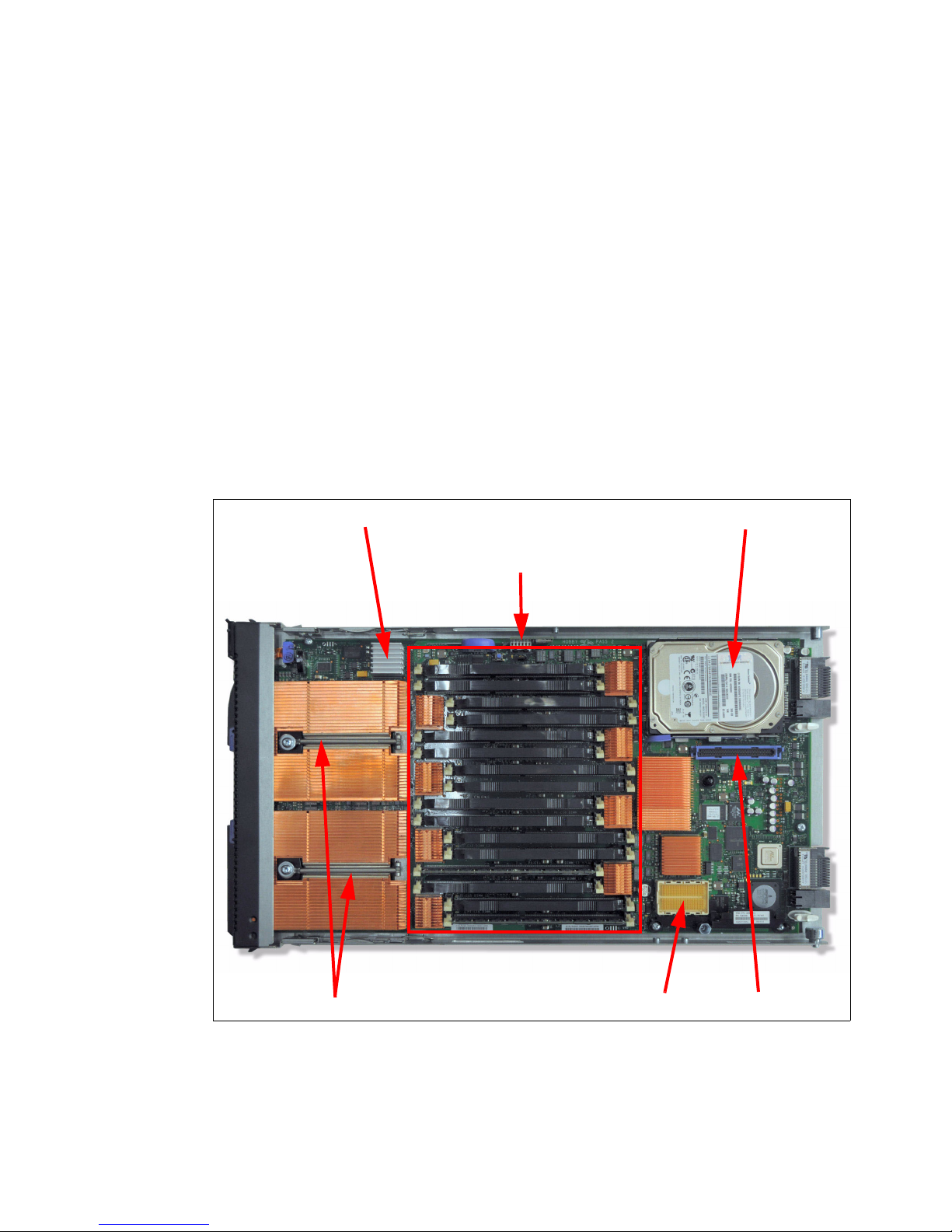
1.6 System features
Two 8-core processors
Disk drive bay
CIOv connectorCFFh connector
SAS disk controller
16 memory DIMM sockets
The PS703 and PS704 blade servers are 16-core and 32-core POWER7 processor-based
blade servers.This section describes the features on each of the POWER7 blade servers.
The following topics are covered:
1.6.1, “PS703 system features” on page 14
1.6.2, “PS704 system features” on page 16
1.6.3, “Minimum features for the POWER7 processor-based blade servers” on page 18
1.6.4, “Power supply features” on page 19
1.6.5, “Processor” on page 20
1.6.6, “Memory features” on page 20
1.6.7, “I/O features” on page 21
1.6.8, “Disk features” on page 26
1.6.9, “Standard onboard features” on page 26
1.6.1 PS703 system features
The BladeCenter PS703 is shown in Figure 1-8.
Figure 1-8 Top view of the PS703 blade server
The features of the server are as follows:
Machine type and model number
7891-73X
14 IBM BladeCenter PS703 and PS704 Technical Overview and Introduction
Page 29

Form factor
Single-wide (30 mm) blade
Processors:
– Two eight-core 64-bit POWER7 processors operating at a 2.4 GHz clock speed for a
total of 16 cores in the blade server
– Based on CMOS 12S 45 nm SOI (silicon-on-insulator) technology
– Power consumption is 110 W per socket
– Single-wide (SW) Blade package
Memory
– 16 DIMM slots
– Minimum 16 GB, maximum capacity 256 GB (using 16 GB DIMMs)
– Industry standard VLP DDR3 DIMMs
– Optional Active Memory Expansion
Disk
– 3 Gb SAS disk storage controller
– One disk drive bay which supports one 2.5-inch SAS HDD (hard disk drive) or two
1.8-inch SATA SSD (solid state drive)
– Hardware mirroring:
• One HDD: RAID 0
• One SSD: RAID 0
• Two SSDs: RAID 0 or RAID 10
On-board integrated features:
– Service processor (SP)
– Two 1 Gb Ethernet ports
– One SAS Controller
– USB Controller which routes to the USB 2.0 port on the media tray
– 1 Serial over LAN (SOL) Console through SP
Expansion Card I/O Options:
– One CIOv expansion card slot (PCIe)
– One CFFh expansion card slot (PCIe)
Chapter 1. Introduction and general description 15
Page 30

1.6.2 PS704 system features
Two 8-core processors
Drive bay
CIOv connectorCFFh connector
16 DIMM sockets
Thumb-screw
sockets
SMP connector to join the
PS704 base blade and SMP
blade together
The PS704 is a double-wide server. The two halves of the BladeCenter PS704 are shown in
Figure 1-9 on this page and Figure 1-10 on page 17.
Figure 1-9 Top view of PS704 blade server base unit
16 IBM BladeCenter PS703 and PS704 Technical Overview and Introduction
Page 31

Figure 1-10 Top view of PS704 blade server SMP unit
Two 8-core processors
Disk drive bay
CIOv connectorCFFh connector
SAS disk controller
16 DIMM sockets
Thumb screw to
attach to PS704 base
blade
SMP connector (on
the underside)
The features of the server are as follows:
Machine type and model number
7891-74X
Form factor
Double-wide (60 mm) blade
Processors:
– Four eight-core 64-bit POWER7 processors operating at a 2.4 GHz clock speed for a
total of 32 cores in the blade server
– Based on CMOS 12S 45 nm SOI (silicon-on-insulator) technology
– Power consumption is 110W per socket
Memory
– 32 DIMM slots
– Minimum 32 GB, maximum capacity 512 GB (using 16 GB DIMMs)
– Industry standard VLP DDR3 DIMMs
– Optional Active Memory Expansion
Disk
– 3 Gb SAS disk storage controller which is located in the SMP unit
Chapter 1. Introduction and general description 17
Page 32

– Two disk drive bays supporting up to two 2.5-inch SAS HDD (hard disk drive) or up to
four 1.8-inch SAS SSD (solid state drive)
– Hardware mirroring:
• One HDD: RAID 0
• One SSD: RAID 0
• Two HDDs: RAID 0 or RAID 10
• One HDD and one SSD: RAID 0 on each disk; combining HDD and SSD in one
RAID configuration is not allowed.
• Two SSDs: RAID 0 or RAID 10
• Three SSDs: RAID 0, RAID 5, or RAID 10 (RAID 10 with only two disks)
• Four SSDs: RAID 0, RAID 5, RAID 6, or RAID 10
On-board integrated features:
– Service processor (one on each blade
1
)
– Four 1 Gb Ethernet ports
– One SAS Controller
– USB Controller which routes to the USB 2.0 port on the media tray
– 1 Serial over LAN (SOL) Console through FSP
Expansion Card I/O Options:
– Two CIOv expansion card slots (PCIe)
– Two CFFh expansion card slots (PCIe)
1.6.3 Minimum features for the POWER7 processor-based blade servers
At the minimum a PS703 requires a BladeCenter chassis, two eight-core 2.4 GHz
processors, minimum memory of 16 GB, zero or one disks, and a Language Group Specify
(mandatory to order voltage nomenclature/language).
At the minimum a PS704 requires a BladeCenter chassis, four eight-core 2.4 GHz
processors, minimum memory of 32GB, zero or one disks, and a Language Group Specify
(mandatory to order voltage nomenclature/language).
Each system has a minimum feature set to be valid. The minimum system configuration for
PS703 and PS704 blade servers is shown in Table 1-6 on page 19.
1
The service processor (or flexible service processor) on the expansion unit provides control but does not offer
redundancy with the SP on the base unit.
18 IBM BladeCenter PS703 and PS704 Technical Overview and Introduction
Page 33

Table 1-6 Minimum features for PS703 and PS704 blade server
Category Minimum features required
BladeCenter chassis Supported BladeCenter chassis
Refer to 1.3.1, “Supported BladeCenter chassis” on page 5
Processor Two 8-core 2.4 GHz Processors in a PS703 Blade (7891-73X)
Four 8-core 2.4 GHz Processors in a PS704 Blade(7891-74X)
Memory DDR3 Memory DIMM
For PS703:
16GB - two 8 GB (2 x 4 GB DIMMs) DDR3 1066 MHz (#8196) or one 16 GB (2
x 8 GB DIMMs) DDR3 1066 MHz (#8199
For PS704:
32 GB - four 8 GB (2 x 4 GB DIMMs) DDR3 1066 MHz (#8196) or two 16 GB (2
x 8 GB DIMMs) DDR3 1066 MHz (#8199)
Storage AIX/Linux/Virtual I/O Server/IBM i (Required VIOS partition):
300 GB SAS 2.5-inch HDD (#8274) or
600 GB SAS 2.5 inch HDD (#8276) or
177 GB SATA SSD (#8207)
If Boot from SAN 8 GB Fibre Channel HBA is selected with FC #8240, #8242 or
#8271 or Fibre Channel over Ethernet Adapter FC #8275 must be ordered.
)
FC #8207 requires FC #4539 - Interposer for 1.8-inch Solid® State Drives
1x Language Group Country specific (selected by the customer)
Operating system 1x primary operating system (one of the following)
AIX (#2146)
Linux (#2147)
IBM i (#2145) plus IBM i 6.1.1 (#0566)
IBM i (#2145) plus IBM i 7.1 (#0567)
1.6.4 Power supply features
The peak power consumption is 428 W for the PS703 and 848 W for the PS704 blade server;
power is provided by the BladeCenter power supply modules. The maximum measured value
is the worst case power consumption expected from a fully populated server under intensive
workload. The maximum measured value also takes into account component tolerance and
non-ideal operating conditions. Power consumption and heat load vary greatly by server
configuration and use.
Use the IBM Systems Energy Estimator to obtain a heat output estimate based on a specific
configuration. The Estimator is available from the following web page:
http://www-912.ibm.com/see/EnergyEstimator
For information about power supply requirements for each of the BladeCenter chassis
supported by POWER7 blade servers and the number of POWER7 blades supported, see
1.3.2, “Number of PS703 and PS704 blades in a chassis” on page 12.
Chapter 1. Introduction and general description 19
Page 34

1.6.5 Processor
The processors used in the PS703 and PS704 are 64-bit POWER7 processors operating at
2.4 GHz. They are optimized to achieve maximum performance for both the system and its
virtual machines. Couple that performance with PowerVM and you are now enabled for
massive workload consolidation to drive maximum system use, predictable performance, and
cost efficiency.
POWER7 Intelligent Threads Technology enables workload optimization by selecting the
most suitable threading mode (Single thread (per core) or Simultaneous Multi-thread 2 or 4
modes, also called 2-SMT and 4-SMT). The Intelligent Threads Technology can provide
improved application performance. In addition, POWER7 processors can maximize cache
access to cores, improving performance, using Intelligent Cache technology.
EnergyScale™ Technology offers Intelligent Energy management features, which can
dramatically and dynamically conserve power and further improve energy efficiency. These
Intelligent Energy features enable the POWER7 processor to operate at a higher frequency if
environmental conditions permit, for increased performance per watt. Alternatively, if user
settings permit, these features allow the processor to operate at a reduced frequency for
significant energy savings.
The PS703 and PS704 come with a standard processor configuration. There are no optional
processor configurations for the PS703 and PS704. The PS703 and PS704 processor
configurations are as follows:
The PS703 blade server is a single-wide blade that contains two eight-core, 64-bit
POWER7 2.4 GHz processors with 256 KB per processor core L2 cache and 4 MB per
processor core L3 cache. No processor options are available.
The PS704 blade server is a double-wide blade that supports four eight-core, 64-bit
POWER7 2.4 GHz processor with 256 KB per processor core L2 cache and 4 MB per
processor core L3 cache. No processor options are available.
1.6.6 Memory features
The PS703 and PS704 blade servers uses industry standard VLP DDR3 memory DIMMs.
Memory DIMMs must be installed in matched pairs with the same size and speed. For details
about the memory subsystem and layout, see 2.4, “Memory subsystem” on page 47.
The PS703 and PS704 blade serves have 16 and 32 DIMM slots, respectively. Memory is
available in 4 GB, 8 GB, or 16 GB DIMMs, all operating at a memory speed of 1066 MHz. The
memory sizes can be mixed within a system.
The POWER7 DDR3 memory uses a new memory architecture to provide greater bandwidth
and capacity. This enables operating at a higher data rate for larger memory configurations.
For details, see 2.4, “Memory subsystem” on page 47. Table 1-7 shows the DIMM features.
Table 1-7 Memory DIMM options
Feature code Total memory size Package includes Speed
8196 8 GB Two 4 GB DIMMs 1066 MHz
8199 16 GB Two 8 GB DIMMs 1066 MHz
EM34 32 GB Two 16 GB DIMMs 1066 MHz
20 IBM BladeCenter PS703 and PS704 Technical Overview and Introduction
Page 35

Notes:
The DDR2 DIMMs used in JS23 and JS43 blade servers are not supported in the
POWER7 blade servers.
The DDR3 DIMMs used in PS700, PS701, and PS702 blade servers are not supported
in the PS703 and PS704 blade servers.
The optional Active Memory Expansion is a POWER7 technology that allows the effective
maximum memory capacity to be much larger than the true physical memory. Compression
and decompression of memory content using processor cycles can allow memory expansion
up to 100%. This can allow an AIX 6.1 (or later) partition to do significantly more work with the
same physical amount of memory or a server to run more partitions and do more work with
the same physical amount of memory. For more information, see 2.5, “Active Memory
Expansion” on page 52.
1.6.7 I/O features
The PS703 has one CIOv PCIe expansion card slot and one CFFh PCIe high-speed
expansion card slot. The PS704 blade server has two CIOv expansion card slots and two
CFFh expansion card slots.
Table 1-8 shows the CIOv and CFFh expansion cards supported in the PS703 and PS704
servers.
Table 1-8 I/O expansion cards supported in the PS703 and PS704
Card Description Feature Code
CIOv
QLogic 8 Gb Fibre Channel Expansion Card (CIOv) 8242
QLogic 4 Gb Fibre Channel Expansion Card (CIOv) 8241
Emulex 8 Gb Fibre Channel Expansion Card (CIOv) 8240
3 Gb SAS Passthrough Expansion Card (CIOv) 8246
Broadcom 2-Port Gb Ethernet Expansion Card (CIOv) 8243
CFFh
QLogic 1Gb Ethernet and 8 Gb Fibre Channel Expansion Card (CFFh) 8271
QLogic 1 Gb Ethernet and 4 Gb Fibre Channel Expansion Card (CFFh) 8252
QLogic 2-port 10 Gb Converged Network Adapter (CFFh) 8275
2-Port QDR 40 GB/s InfiniBand Expansion Card (CFFh) 8272
Broadcom 2/4-Port Ethernet Expansion Card (CFFh) 8291
QLogic 8 Gb Fibre Channel Expansion Card (CIOv)
The QLogic 8 Gb Fibre Channel Expansion Card (CIOv) for IBM BladeCenter, feature #8242,
enables high-speed access for IBM blade servers to connect to a Fibre Channel storage area
network (SAN). When compared to the previous-generation 4 Gb adapters, the new adapter
doubles the throughput speeds for Fibre Channel traffic. As a result, you can manage
increased amounts of data and possibly benefit from a reduced hardware cost.
Chapter 1. Introduction and general description 21
Page 36

The card has the following features:
CIOv form factor
QLogic 2532 8 Gb ASIC
PCI Express 2.0 host interface
Support for two full-duplex Fibre Channel ports at 8 Gbps maximum per channel
Support for Fibre Channel Protocol Small Computer System Interface (FCP-SCSI) and
Fibre Channel Internet Protocol (FC-IP)
Support for Fibre Channel service (class 3)
Support for switched fabric, point-to-point, and Fibre Channel Arbitrated Loop (FC-AL)
connections
Support for NPIV
For more information, see the IBM Redbooks at-a-glance guide at the following web page:
http://www.redbooks.ibm.com/abstracts/tips0692.html?Open
QLogic 4 Gb Fibre Channel Expansion Card (CIOv)
The QLogic 4 Gb Fibre Channel Expansion Card (CIOv) for BladeCenter, feature #8241,
enables you to connect the BladeCenter servers with CIOv expansion slots to a Fibre
Channel SAN. Pick any Fibre Channel storage solution from the IBM System Storage®
DS3000, DS4000®, DS5000, and DS8000® series, and begin accessing data over a
high-speed interconnect. This card is installed into the PCI Express CIOv slot of a supported
blade server. It provides connections to Fibre Channel-compatible modules located in bays 3
and 4 of a supported BladeCenter chassis. A maximum of one QLogic 4 Gb Fibre Channel
Expansion Card (CIOv) is supported per single-wide (30 mm) blade server.
The card has the following features:
CIOv form factor
PCI Express 2.0 host interface
Support for two full-duplex Fibre Channel ports at 4 Gbps maximum per channel
Support for Fibre Channel Protocol SCSI (FCP-SCSI) and Fibre Channel Internet Protocol
(FC-IP)
Support for Fibre Channel service (class 3)
Support for switched fabric, point-to-point, and Fibre Channel Arbitrated Loop (FC-AL)
connections
For more information, see the IBM Redbooks at-a-glance guide at the following web page:
http://www.redbooks.ibm.com/abstracts/tips0695.html?Open
Emulex 8 Gb Fibre Channel Expansion Card (CIOv)
The Emulex 8 Gb Fibre Channel Expansion Card (CIOv) for IBM BladeCenter, feature #8240,
enables high-performance connection to a SAN. The innovative design of the IBM
BladeCenter midplane enables this Fibre Channel adapter to operate without the need for an
optical transceiver module. This saves significant hardware costs. Each adapter provides
dual paths to the SAN switches to ensure full redundancy. The exclusive firmware-based
architecture allows firmware and features to be upgraded without taking the server offline or
rebooting, and without the need to upgrade the driver.
The card has the following features:
Support of the 8 Gbps Fibre Channel standard
Use of the Emulex “Saturn” 8 Gb Fibre Channel I/O Controller (IOC) chip
Enablement of high-speed and dual-port connection to a Fibre Channel SAN
Can be combined with a CFFh card on the same blade server
22 IBM BladeCenter PS703 and PS704 Technical Overview and Introduction
Page 37

Comprehensive virtualization capabilities with support for N_Port ID Virtualization (NPIV)
and Virtual Fabric
Simplified installation and configuration using common HBA drivers
Efficient administration by using HBAnyware for HBAs anywhere in the SAN
Common driver model that eases management and enables upgrades independent of
HBA firmware
Support of BladeCenter Open Fabric Manager
Support for NPIV when installed in the PS703 and PS704 blade servers
For more information, see the IBM Redbooks at-a-glance guide at the following web page:
http://www.redbooks.ibm.com/abstracts/tips0703.html?Open
3 Gb SAS Passthrough Expansion Card (CIOv)
This card, feature #8246, is an expansion card that offers the ideal way to connect the
supported BladeCenter servers to a wide variety of SAS storage devices. The SAS
connectivity card can connect to the Disk Storage Modules in the BladeCenter S. The card
routes the pair of SAS channels from the blade’s onboard SAS controller to the SAS switches
installed in the BladeCenter chassis.
Tip: This card is also known as the SAS Connectivity Card (CIOv) for IBM BladeCenter.
This card is installed into the CIOv slot of the supported blade server. It provides connections
to SAS modules located in bays 3 and 4 of a supported BladeCenter chassis.
The card has the following features:
CIOv form factor
Provides external connections for the two SAS ports of the blade server's onboard SAS
controller
Support for two full-duplex SAS ports at 3 Gbps maximum per channel
Support for SAS, SSP, and SMP protocols
Connectivity to SAS storage devices
For more information, see the IBM Redbooks at-a-glance guide at the following web page:
http://www.redbooks.ibm.com/abstracts/tips0701.html?Open
Broadcom 2-Port Gb Ethernet Expansion Card (CIOv)
The Broadcom 2-port Gb Ethernet Expansion Card (CIOv) is an Ethernet expansion card with
two 1 Gb Ethernet ports designed for BladeCenter servers with CIOv expansion slots.
The card has the following features:
PCI Express host interface
Broadcom BCM5709S communication module
BladeCenter Open Fabric Manager (BOFM) support
Connection to 1000BASE-X environments using BladeCenter Ethernet switches
Full-duplex (FDX) capability, enabling simultaneous transmission and reception of data on
the Ethernet local area network (LAN)
TCPIP checksum offload
TCP segmentation offload
For more detail see the IBM Redbooks publication IBM BladeCenter Products and
Technology, SG24-7523, available at the following web page:
http://www.redbooks.ibm.com/abstracts/sg247523.html?Open
Chapter 1. Introduction and general description 23
Page 38

QLogic 1 Gb Ethernet and 8 Gb Fibre Channel Expansion Card (CFFh)
The QLogic 1Gb Ethernet and 8Gb Fibre Channel Expansion Card, feature #8271, is a CFFh
high speed blade server expansion card with two 8Gb Fibre Channel ports and two 1 Gb
Ethernet ports. It provides QLogic 2532 PCI-Express ASIC for 8 Gb 2-port Fibre Channel and
Broadcom 5709S ASIC for 1 Gb 2-port Ethernet. This card is used in conjunction with the
Multi-Switch Interconnect Module and is installed in the left position of the MSIM and a Fibre
Channel capable I/O module is installed in the right position of the MSIM. Both switches do
not need to be present at the same time because the Fibre Channel and Ethernet networks
are separate and distinct. It can be combined with a CIOv I/O card on the same high-speed
blade server.
The card has the following features:
Broadcom 5709S ASIC with two 1Gb Ethernet ports
PCI Express host interface
BladeCenter Open Fabric Manager (BOFM) support
TCPIP checksum offload
TCP segmentation offload
Full-duplex (FDX) capability
QLogic 2532 ASIC with two 8Gb Fibre Channel ports
Support for FCP-SCSI and FCP-IP
Support for point-to-point fabric connection (F-port fabric login)
Support for Fibre Channel service (classes 2 and 3)
Support for NPIV when installed in PS703 and PS704 blade servers
Support for remote startup (boot) operations
Support for BladeCenter Open Fabric Manager
Support for Fibre Device Management Interface (FDMI) standard (VESA standard)
Fibre Channel 8 Gbps, 4 Gbps, or 2 Gbps auto-negotiation
For more information, see the IBM Redbooks at-a-glance guide at the following web page:
http://www.redbooks.ibm.com/abstracts/tips0690.html?Open
QLogic 1 Gb Ethernet and 4 Gb Fibre Channel Expansion Card (CFFh)
The QLogic Ethernet and 4 Gb Fibre Channel Expansion Card, feature #8252, is a CFFh high
speed blade server expansion card with two 4 Gb Fibre Channel ports and two 1 Gb Ethernet
ports. It provides QLogic 2432M PCI-Express x4 ASIC for 4 Gb 2-port Fibre Channel and
Broadcom 5715S PCI-Express x4 ASIC for 1 Gb 2-port Ethernet. This card is used in
conjunction with the Multi-Switch Interconnect Module and is installed in the left position of
the MSIM and a Fibre Channel capable I/O module is installed in the right position of the
MSIM. Both switches do not need to be present at the same time because the Fibre Channel
and Ethernet networks are separate and distinct. It can be combined with a CIOv I/O card on
the same high-speed blade server.
The card has the following features:
Support for FCP-SCSI and FCP-IP
Support for point-to-point fabric connection (F-port fabric login)
Support for remote startup (boot) operations
Support for BladeCenter Open Fabric Manager
For more detail see the IBM Redbooks publication IBM BladeCenter Products and
Technology, SG24-7523, available at the following web page:
http://www.redbooks.ibm.com/abstracts/sg247523.html?Open
24 IBM BladeCenter PS703 and PS704 Technical Overview and Introduction
Page 39

QLogic 2-port 10 Gb Converged Network Adapter (CFFh)
The QLogic 2-port 10 Gb Converged Network Adapter (CFFh) for IBM BladeCenter, feature
#8275, offers robust Fibre Channel storage connectivity and 10 Gb networking over a single
Converged Enhanced Ethernet (CEE) link. Because this adapter combines the functions of a
network interface card and a host bus adapter on a single converged adapter, clients can
realize potential benefits in cost, power, and cooling, and data center footprint by deploying
less hardware.
The card has the following features:
CFFh PCI Express 2.0 x8 adapter
Communication module: QLogic ISP8112
Support for up to two CEE HSSMs in a BladeCenter H or HT chassis
Support for 10 Gb Converged Enhanced Ethernet (CEE)
Support for Fibre Channel over Converged Enhanced Ethernet (FCoCEE)
Full hardware offload for FCoCEE protocol processing
Support for IPv4 and IPv6
Support for SAN boot over CEE, PXE boot, and iSCSI boot
Support for Wake on LAN
For more information, see the IBM Redbooks at-a-glance guide at the following web page:
http://www.redbooks.ibm.com/abstracts/tips0716.html?Open
2-Port QDR 40 Gbps InfiniBand Expansion Card (CFFh)
The 2-Port 40 Gbps InfiniBand Expansion Card (CFFh) for IBM BladeCenter is a dual port
InfiniBand Host Channel Adapter (HCA) based on proven Mellanox ConnectX IB technology.
This HCA, when combined with the QDR switch, delivers end-to-end 40 Gb bandwidth per
port. This solution is ideal for low latency, high bandwidth, performance-driven and storage
clustering application in a High Performance Compute environment.
The card has the following features:
1s MPI ping latency
Dual 4X InfiniBand ports at speeds of 10 Gbps, 20 Gbps, or 40 Gbps per port
CPU offload of transport operations
End-to-end QoS and congestion control
Hardware-based I/O virtualization
Multi-protocol support
TCP/UDP/IP stateless offload
2-port card allows use of two 40 Gb High-Speed Switch Modules (HSSM) in a chassis
For more information, see the IBM Redbooks at-a-glance guide at the following web page:
http://www.redbooks.ibm.com/abstracts/tips0700.html?Open
Broadcom 2/4-Port Ethernet Expansion Card (CFFh)
The 2/4-Port Ethernet Expansion Card (CFFh) for IBM BladeCenter allows the addition of up
to four (in IBM BladeCenter H chassis) or two (in BladeCenter S) extra 1 Gb ports, thereby
allowing the use of 6 or 4 ports per blade, respectively.
The card has the following features:
Based on the Broadcom 5709S module
PCI Express x4 host interface for high-speed connection
Connectivity to either standard or high-speed I/O modules bays (depends on chassis)
Multiple connections from the blade server to the external network
Chapter 1. Introduction and general description 25
Page 40

Ability to function as a 2-port Ethernet NIC in BladeCenter S chassis or a 4-Port Ethernet
NIC in a BladeCenter H chassis
Supports BladeCenter Open Fabric Manager (BOFM)
Network install and boot support with adapter firmware update
For more information, see the IBM Redbooks at-a-glance guide at the following web page:
http://www.redbooks.ibm.com/abstracts/tips0698.html?Open
1.6.8 Disk features
The PS703 blade servers have one disk bay. The bay supports either of the following:
One 2.5-inch SAS HDD
One or two 1.8-inch SATA solid state drives (SSDs)
If you elect to use SSDs, then the Interposer for 1.8-inch Solid State Drives, feature code
4539 must also be installed.
The PS704 blade servers have two disk bays (one on the base card and one in the expansion
unit of the blade):
On the base unit, it can have one 2.5-inch SAS HDD.
On the base unit, it can have up to two 1.8-inch SATA SSDs.
On the expansion unit, it can have one 2.5-inch SAS HDD.
On the expansion unit, it can have up to two 1.8-inch SATA SSDs.
Table 1-6 lists the supported disk features on the PS703 and PS704 blade servers.
Table 1-9 Supported disk drives and options
Feature code Description
2.5-inch SAS drives
8274 300 GB 10K SFF SAS HDD
8276 600 GB 10K SFF SAS HDD
1.8-inch solid state drive (SSD) and interposer
8207 177 GB SATA SSD (requires feature 4539)
4539 Interposer for 1.8-inch Solid State Drives
1.6.9 Standard onboard features
In this section, we describe the standard on-board features.
Service processor
The service processor (or flexible service processor, FSP) is the main integral part of the
blade server. It monitors and manages system hardware, resources, and devices. It does the
system initialization, configuration, and thermal/power management. It takes corrective action
if required.
The PS703 has only one service processor. The PS704 blade server has two FSPs (one on
each blade). However, the second service processor is only in IO mode and is not redundant
to the one on the base blade.
26 IBM BladeCenter PS703 and PS704 Technical Overview and Introduction
Page 41

For more details about service processors, see 2.8, “Service processor” on page 65.
SSD
Interposer
Connectors
on the SSD
Interposer for
the two SSDs
Solid-state
drive
Ethernet ports
The PS703 has a 2-port onboard integrated Ethernet adapter for a total of two Ethernet ports.
The PS704 has two 2-port onboard integrated Ethernet adapters with one in the base blade
and the second one in the SMP blade for a total of four Ethernet ports.
Note: The PS703 and PS704 do not have the Host Ethernet Adapters (HEAs) and
Integrated Virtual Ethernet (IVE) ports that previous Power blade servers have included. A
virtual Ethernet can be provided from the Virtual I/O Server virtual network environment.
For more details about Ethernet ports, see 2.7.5, “Embedded Ethernet Controller” on
page 63.
SAS Controller
The PS703 blade server has one integrated SAS controller. The PS704 has one integrated
SAS controller located on the SMP blade.
The integrated SAS controller is used to drive the local SAS storage. This SAS controller can
also support SATA SSD with the addition of the SSD Interposer for 1.8-inch solid-state drives
as shown in Figure 1-11.
Figure 1-11 Interposer for 1.8-inch Solid State Drives
The integrated SAS controller supports hardware RAID 0, RAID 5, RAID 6, or RAID 10
depending on the number of drives installed.
The 3 Gb SAS Passthrough Expansion Card can be used to connect to the BladeCenter SAS
Connectivity Module, which can be connected to the external storage. This SAS pass-through
expansion card can also be used to connect to BladeCenter S internal drive SAS drives. See
“3 Gb SAS Passthrough Expansion Card (CIOv)” on page 23 for more information. See also
“SAS adapter” on page 61 and 2.9, “Internal storage” on page 68.
USB controller
The USB controller connects the USB bus to the midplane, which is then routed to the media
tray in the BladeCenter chassis to connect to USB devices (such as an optical drive or
diskette drive).
For more information, see 2.7.6, “Embedded USB controller” on page 64.
Chapter 1. Introduction and general description 27
Page 42

Serial over LAN (SOL)
The integrated SOL function routes the console data stream over standard dual 1 Gb
Ethernet ports to the Advance Management Module. The PS703 and PS704 do not have
on-board video chips and do not support KVM connections. Console access is only by SOL
connection. Each blade can have a single SOL session; however, there can be multiple telnet
or ssh sessions to the BladeCenter AMM, each acting as a SOL connection to a different
blade.
For more information, see 2.8.1, “Server console access by SOL” on page 65.
1.7 Supported BladeCenter I/O modules
With IBM BladeCenter, the switches and other I/O modules are installed in the chassis rather
than as discrete devices installed in the rack.
The BladeCenter chassis supports a wide variety and range of I/O switch modules. These
switch modules are matched to the type, slot location, and form factor of the expansion cards
installed in a blade server. For more information, see 1.6.7, “I/O features” on page 21 and 2.7,
“Internal I/O subsystem” on page 55.
The I/O switch modules described in the following sections are matched with the on-board
Broadcom 2-port BCM5709S network controller ports along with the supported expansion
card ports in the PS703 and PS704 blades.
For the latest and most current information about blade, expansion card, switch module, and
chassis compatibility and interoperability see the IBM BladeCenter Interoperability Guide at
the following web page:
http://www.ibm.com/support/docview.wss?uid=psg1MIGR-5073016
1.7.1 Ethernet switch and intelligent pass-through modules
Various types of Ethernet switch and pass-through modules from several manufacturers are
available for BladeCenter, and they support different network layers and services. These I/O
modules provide external and chassis blade-to-blade connectivity.
The Broadcom 2-port BCM5709S network controller, along with the supported expansion
cards in the PS703 and PS704 blades, provides Ethernet connectivity. For more information,
see 2.7.5, “Embedded Ethernet Controller” on page 63. There are two physical ports on the
PS703 and four physical ports on the PS704. The data traffic from these on-blade 1 Gb
Ethernet adapter ports is directed to I/O switch bays 1 and 2 respectively on all BladeCenter
chassis except BladeCenter S. On the BladeCenter S the connections for all blade Ethernet
ports are wired to I/O switch bay 1.
To provide external network connectivity and a SOL system console through the BladeCenter
Advanced Management Module, at least one Ethernet I/O module is required in switch bay 1.
For more information, see 2.8.1, “Server console access by SOL” on page 65.
In addition to the onboard Ethernet ports, the QLogic Ethernet and 4 Gb Fibre Channel
Expansion Card (CFFh) adapter can provide two additional 1 Gb Ethernet ports per card.
A list of available Ethernet I/O modules that support the on-blade Ethernet ports and
expansion card are shown in Table 1-10 on page 29. Not all switches are supported in every
28 IBM BladeCenter PS703 and PS704 Technical Overview and Introduction
Page 43

configuration of BladeCenter. Complete compatibility matrixes are available on the following
web pages:
ServerProven®:
http://www.ibm.com/servers/eserver/serverproven/compat/us/eserver.html
BladeCenter Interoperability Guide
http://www.ibm.com/support/docview.wss?uid=psg1MIGR-5073016
Table 1-10 Ethernet switch modules
Part
number
43W4395 3174 Cisco Catalyst Switch Module 3012 4 x Gigabit Ethernet Layer 2/3
Feature
a
code
Option description Number x type
of external ports
Network
layers
41Y8523 3173 Cisco Catalyst Switch Module 3110G 4 x Gigabit Ethernet,
2 x StackWise Plus
41Y8522 3171 Cisco Catalyst Switch Module 3110X 1 x 10 Gb Ethernet,
2 x StackWise Plus
32R1888 Not avail Cisco Systems Intelligent Gb Fiber Ethernet Switch 4 x Gigabit Ethernet Layer 2
32R1892 Not avail Cisco Systems Intelligent Gb Ethernet Switch 4 x Gigabit Ethernet Layer 2
39Y9324 3220 IBM Server Connectivity Module 6 x Gigabit Ethernet Layer 2
32R1860 3212 BNT® L2/3 Copper Gigabit Ethernet Switch Module 6 x Gigabit Ethernet Layer 2/3
32R1861 3213 BNT L2/3 Fibre Gigabit Ethernet Switch Module 6 x Gigabit Ethernet Layer 2/3
32R1859 3211 BNT Layer 2-7 Gigabit Ethernet Switch Module 4 x Gigabit Ethernet Layer 2/7
44W4404 1590 BNT 1/10 Gb Uplink Ethernet Switch Module 3 x 10 Gb Ethernet,
6 x Gigabit Ethernet
a. These feature codes are for the Power Systems ordering system (eConfig)
Layer 2/3
Layer 2/3
Layer 2/3
1.7.2 SAS I/O modules
SAS I/O modules provide affordable storage connectivity for BladeCenter chassis using SAS
technology to create simple fabric for external shared or non-shared storage attachments.
The SAS RAID Controller Module can perform RAID controller functions inside the
BladeCenter S chassis for HDDs installed into Disk Storage Module (DSM). The SAS RAID
Controller Module and DSMs in a BladeCenter S provides RAID 0, 5, 6, and 10 support.
The SAS Controller Module (non-RAID) supports the external storage EXP3000 but binds
that enclosure to a specific blade.
The DSM, part number 43W3581 feature 4545, must be installed in the BladeCenter S
chassis to support external SAS storage devices outside the chassis using the SAS
Connectivity Card. No HDDs need to be installed in the DSM to support the external storage.
In the PS703 and PS704 blades, the 3 Gb SAS Passthrough Expansion Card (CIOv) is
required for external SAS connectivity. The SAS expansion card requires SAS I/O modules in
switch bays 3 and 4 of all supported BladeCenters.
Table 1-11 on page 30 lists the SAS I/O modules and support matrix.
Chapter 1. Introduction and general description 29
Page 44

Table 1-11 SAS I/O modules supported by the SAS pass through card
Feature
Part number
39Y9195 3267 SAS Connectivity Module Ye s Ye s Ye s Yes Ye s N o N o
code
a
Description
3 Gb SAS
pass-thru
card
BC-E
BC-H
BC-HT
BC-S
MSIM
MSIM-HT
43W3584 3734 SAS RAID Controller Module
a. These feature codes are for the Power Systems ordering system (eConfig)
Yes NoNoNoYe s N o N o
1.7.3 Fibre Channel switch and pass-through modules
Fibre Channel I/O modules are available from several manufacturers. These I/O modules can
provide full SAN fabric support up to 8 Gb.
The following 4 Gb and 8 Gb Fibre Channel cards are CIOv form factor and require a Fibre
Channel switch or Intelligent Pass-Through module in switch bays 3 and 4 of all supported
BladeCenters. The CIOv expansion cards are as follows:
Emulex 8 Gb Fibre Channel Expansion Card (CIOv)
QLogic 4 Gb Fibre Channel Expansion Card (CIOv)
QLogic 8 Gb Fibre Channel Expansion Card (CIOv)
Additional 4 Gb and 8 Gb Fibre Channel ports are also available in the CFFh form factor
expansion cards. These cards require the use of the MSIM in a BladeCenter H or the MSIM-HT in
a BladeCenter HT, plus Fibre Channel I/O modules. The CFFh Fibre Channel cards are as
follows:
QLogic Ethernet and 4 Gb Fibre Channel Expansion Card (CFFh)
QLogic 8 Gb Fibre Channel Expansion Card (CFFh)
A list of available Fibre Channel I/O modules that support the CIOv and CFFh expansion
cards is shown in Table 1-12 on page 31. Not all modules are supported in every
configuration of BladeCenter. Complete compatibility matrixes are available on the following
web pages:
ServerProven:
http://www.ibm.com/servers/eserver/serverproven/compat/us/eserver.html
BladeCenter Interoperability Guide
http://www.ibm.com/support/docview.wss?uid=psg1MIGR-5073016
30 IBM BladeCenter PS703 and PS704 Technical Overview and Introduction
Page 45

Table 1-12 Fibre Channel I/O modules
Part
number
32R1812 3206 Brocade 20-port SAN Switch Module 6 4 Gbps
32R1813 3207 Brocade 10-port SAN Switch Module
42C1828 5764 Brocade Enterprise 20-port 8 Gb SAN Switch Module 6 8 Gbps
44X1920 5869 Brocade 20-port 8 Gb SAN Switch Module 6 8 Gbps
44X1921 5045 Brocade 10-port 8 Gb SAN Switch Module 6 8 Gbps
39Y9280 3242 Cisco Systems 20-port 4 Gb FC Switch Module 6 4 Gbps
39Y9284 3241 Cisco Systems 10-port 4 Gb FC Switch Module
43W6725 3244 QLogic 20-port 4 Gb SAN Switch Module 6 4 Gbps
43W6724 3243 QLogic 10-port 4 Gb SAN Switch Module
43W6723 3245 QLogic 4 Gb Intelligent Pass-thru Module
44X1905 3284 QLogic 20-Port 8 Gb SAN Switch Module 6 8 Gbps
44X1907 5449 QLogic 8 Gb Intelligent Pass-thru Module
44W4483 5452 Intelligent Copper Pass-thru Module 14 1 Gbps
a. These feature codes are for the Power Systems ordering system (eConfig)
b. Only 10 ports are activated on these switches. An optional upgrade to 20 ports (14 internal + 6 external) is
available.
c. Can be upgraded to full fabric switch
Feature
a
code
Description Number of
external
ports
b
b
b
c
c
6 4 Gbps
6 4 Gbps
6 4 Gbps
6 4 Gbps
6 8 Gbps
Port
interface
bandwidth
1.7.4 Converged networking I/O modules
There are two basic solutions to implement Fibre Channel over Ethernet (FCoE) over a
converged network with a BladeCenter.
The first solution uses a top-of-rack FCoE-capable switch in conjunction with converged-
network-capable 10 Gb Ethernet I/O modules in the BladeCenter. The FCoE-capable
top-of-rack switch provides connectivity to the SAN.
The second BladeCenter H solution uses a combination of converged-network-capable
10 Gb Ethernet switch modules and fabric extension modules to provide SAN
connectivity, all contained within the BladeCenter H I/O bays.
Implementing either solution with the PS703 and PS704 blades requires the QLogic 2-port
10 Gb Converged Network Adapter (CFFh). The QLogic Converged Network Adapter (CNA)
provides 10 Gb Ethernet and 8 Gb Fibre Channel connectivity over a single CEE link. This
card is a CFFh form factor with connections to BladeCenter H and HT I/O module bays 7
and 9.
Table 1-13 on page 32 shows the currently available I/O modules that are available to provide
an FCoE solution.
Chapter 1. Introduction and general description 31
Page 46

Table 1-13 Converged network modules supported by the QLogic CNA
Part
Number
46C7191 3248 BNT Virtual Fabric 10 Gb Switch Module for IBM BladeCenter
46M6181 5412 10 Gb Ethernet Pass-Thru Module for BladeCenter
46M6172 3268 QLogic Virtual Fabric Extension Module for IBM BladeCenter
46M6071
Feature
a
Code
2241
Description Number of
b
b
Cisco Nexus 4001I Switch Module for IBM BladeCenter
d e
b c
external ports
10 x 10 Gb SFP+
14 x 10 Gb SFP+
6 x 8 Gb FC SFP
6 x 10 Gb SFP+
69Y1909
Not
Brocade Converged 10 GbE Switch Module for IBM BladeCenter 8 X 10 GB Ethernet
available
a. These feature codes are for the Power Systems ordering system (eConfig).
b. Used for top-of-rack solution.
c. Use with Fabric Extension Module for self contain BladeCenter solution.
d. Also requires BNT Virtual Fabric 10 Gb Switch Module.
e. BladeCenter H only.
For the latest interoperability information see the BladeCenter Interoperability Guide,
available from:
http://ibm.com/support/entry/portal/docdisplay?lndocid=MIGR-5073016
1.7.5 InfiniBand switch module
The Voltaire 40 Gb InfiniBand Switch Module for BladeCenter provides InfiniBand QDR
connectivity between the blade server and external InfiniBand fabrics in non-blocking
designs, all on a single device. Voltaire's high speed module also accommodates
performance-optimized fabric designs using a single BladeCenter chassis or stacking
multiple BladeCenter chassis without requiring an external InfiniBand switch.
The InfiniBand switch module offers 14 internal ports, one to each server, and 16 ports out of
the chassis per switch.
The module's HyperScale architecture also provides a unique interswitch link or mesh
capability to form highly scalable, cost-effective, and low latency fabrics. Because this switch
has 16 uplink ports, they can create a meshed architecture and still have unblocked access to
data using the 14 uplink ports. This solution can scale from 14 to 126 nodes and offers
latency of less than 200 nanoseconds, allowing applications to operate at maximum
efficiency.
8 x 8 Gb FC
The PS703 and PS704 blades connect to the Voltaire switch through the 2-port 40 Gb
InfiniBand Expansion Card. The card is only supported in a BladeCenter H and the two ports
are connected to high speed I/O switch bays 7/8 and 9/10.
Details about the Voltaire 40 Gb InfiniBand Switch Module for the BladeCenter H are shown
in Table 1-14.
Table 1-14 InfiniBand switch module for IBM BladeCenter
Part
number
46M6005 3204 Voltaire 40 Gb InfiniBand Switch Module 16 4X QDR (40 Gbps)
Feature
code
Description Number of
32 IBM BladeCenter PS703 and PS704 Technical Overview and Introduction
external ports
Type of external
ports
Page 47

1.7.6 Multi-switch Interconnect Module
Right bay for Fibre
Channel Switch
Modules
Left bay for Ethernet
Switch Modules
The MSIM is a switch module container that fits in the high speed switch bays (bays 7 and 8
or bays 9 and 10) of the BladeCenter H chassis. Up to two MSIMs can be installed in the
BladeCenter H. The MSIM supports most standard switch modules. I/O module to MSIM
compatibility matrixes can be reviewed at the following web pages:
ServerProven:
http://www.ibm.com/servers/eserver/serverproven/compat/us/eserver.html
BladeCenter Interoperability Guide
http://www.ibm.com/support/docview.wss?uid=psg1MIGR-5073016
With PS703 and PS704 blades, the following expansion cards require an MSIM in a
BladeCenter H chassis:
QLogic Ethernet and 4 Gb Fibre Channel Expansion Card (CFFh)
QLogic 8 Gb Fibre Channel Expansion Card (CFFh)
The MSIM is shown in Figure 1-12.
Note: The MSIM comes standard without any I/O modules installed. They must be ordered
separately. In addition, the use of MSIM modules requires that all four power modules be
installed in the BladeCenter H chassis.
Figure 1-12 Multi-switch Interconnect Module
Table 1-15 shows MSIM ordering information.
Table 1-15 MSIM ordering information
Description Part number Feature
MSIM for IBM BladeCenter 39Y9314 3239
a. These feature codes are for the Power Systems ordering system (eConfig).
Chapter 1. Introduction and general description 33
code
a
Page 48

1.7.7 Multi-switch Interconnect Module for BladeCenter HT
The Multi-switch Interconnect Module for BladeCenter HT (MSIM-HT) is a switch module
container that fits in the high-speed switch bays (bays 7 and 8 or bays 9 and 10) of the
BladeCenter HT chassis. Up to two MSIMs can be installed in the BladeCenter HT. The
MSIM-HT accepts two supported standard switch modules as shown in Figure 1-13.
The MSIM-HT has a reduced number of supported standard I/O modules compared to the
MSIM.
I/O module to MSIM-HT compatibility matrixes can be viewed at the following web pages:
ServerProven:
http://www.ibm.com/servers/eserver/serverproven/compat/us/eserver.html
BladeCenter Interoperability Guide
http://www.ibm.com/support/docview.wss?uid=psg1MIGR-5073016
With PS703 and PS704 blades the QLogic Ethernet and 4 Gb Fibre Channel Expansion Card
(CFFh) requires an MSIM-HT in a BladeCenter HT chassis.
Note: The MSIM-HT comes standard without any I/O modules installed. They must be
ordered separately. In addition, the use of MSIM-HT modules requires that all four power
modules be installed in the BladeCenter HT chassis.
Figure 1-13 Multi-switch Interconnect Module for BladeCenter HT
Table 1-16 shows MSIM-HT ordering information.
Table 1-16 MSIM-HT ordering information
Description Part number Feature
Multi-switch Interconnect Module for BladeCenter HT 44R5913 5491
a. These feature codes are for the Power Systems ordering system (eConfig).
1.8 Building to order
You can perform a build to order configuration using the IBM Configurator for e-business
(e-config). The configurator allows you to select a pre-configured Express model or to build a
34 IBM BladeCenter PS703 and PS704 Technical Overview and Introduction
code
a
Page 49

system to order. Use this tool to specify each configuration feature that you want on the
system, building on top of the base-required features.
1.9 Model upgrades
The PS703 and PS704 are new serial-number blade servers. There are no upgrades from
POWER5™, POWER6, POWER7, and the POWER7 PS700, PS701, and PS702 blade
servers to the POWER7 PS703 and PS704 blade servers, which retain the serial number.
Unlike the upgrade which exists from the PS701 to the PS702, there are no upgrades from
the PS703 to the PS704.
Chapter 1. Introduction and general description 35
Page 50

36 IBM BladeCenter PS703 and PS704 Technical Overview and Introduction
Page 51

Chapter 2. Architecture and technical
2
overview
This chapter discusses the overall system architecture of the POWER7 processor-based
blade servers and provides details about each major subsystem and technology.
The topics covered are:
2.1, “Architecture” on page 38
2.2, “The IBM POWER7 processor” on page 39
2.3, “POWER7 processor-based blades” on page 47
2.4, “Memory subsystem” on page 47
2.5, “Active Memory Expansion” on page 52
2.6, “Technical comparison” on page 54
2.7, “Internal I/O subsystem” on page 55
2.8, “Service processor” on page 65
2.9, “Internal storage” on page 68
2.10, “External disk subsystems” on page 73
2.11, “IVM” on page 81
2.12, “Operating system support” on page 83
2.13, “IBM EnergyScale” on page 85
Note: The bandwidths that are provided throughout the chapter are theoretical maximums
used for reference.
© Copyright IBM Corp. 2011. All rights reserved. 37
Page 52

2.1 Architecture
SMI
SMI
SMI
SMI
SMI
SMI
SMI
SMI
Two x8 Gen2
x8 Gen1
HDD/SSD connector
BCM5709
Gigabit
Ethernet
To chassis
I/O bays
1 & 2
BCM5387
Ethernet
switch
To
media
tray
x1 Gen1
x4 Gen1
Flash
NVRAM
DDR
TPMD
POWER7
Processor 1
POWER7
Processor 0
FSP
DIMM
DIMM
DIMM
DIMM
DIMM
DIMM
DIMM
DIMM
DIMM
DIMM
DIMM
DIMM
DIMM
DIMM
DIMM
DIMM
x8 Gen2
CIOv I/O connector
SAS
4 bytes
each
GX++
4 bytes
CFFh I/O connector
USB
controller
P7IOC
I/O hub
PCIe
to PCI
The overall system architecture is shown in Figure 2-1, with the major components described
in the following sections. Figure 2-1 shows the PS703 layout.
Figure 2-1 PS703 block diagram
The PS704 double-wide blade base planar holds the same components as the PS703
single-wide blade with the exclusion of the SAS controller, which is located on the SMP
planar. The PS704 double-wide blade SMP planar also has the same components with the
exclusion of the USB controller. This means that the components are doubled for the PS704
double-wide blade as compared to the PS703 single-wide blade except for the SAS controller
and USB controller. See 2.7, “Internal I/O subsystem” on page 55 for more details.
Figure 2-2 on page 39 shows the PS704 layout.
38 IBM BladeCenter PS703 and PS704 Technical Overview and Introduction
Page 53

PS704
base
planar
BCM5709
Gigabit
Ethernet
To chassis
I/O bays
1 & 2
BCM5387
Ethernet
switch
To
media
tray
Flash
NVRAM
DDR
TPMD
POWER7
Processor 1
SMI
SMI
SMI
SMI
SMI
SMI
SMI
SMI
DIMM
DIMM
DIMM
DIMM
DIMM
DIMM
DIMM
DIMM
DIMM
DIMM
DIMM
DIMM
DIMM
DIMM
DIMM
DIMM
CIOv I/O connector
SMI
SMI
SMI
SMI
SMI
SMI
SMI
SMI
HDD/SSD connector
BCM5709
Gigabit
Ethernet
To chassis
I/O bays
1 & 2
To FSP
on base
planar
POWER7
Processor 1
DIMM
DIMM
DIMM
DIMM
DIMM
DIMM
DIMM
DIMM
DIMM
DIMM
DIMM
DIMM
DIMM
DIMM
DIMM
DIMM
CIOv I/O connector
HDD/SSD connector
SAS
PS704
SMP
planar
CIOv I/O connector
SAS
POWER7
Processor 0
POWER7
Processor 0
8 bytes
Each
4 bytes
To FSP on SMP planar
FSP
4 bytes
4 bytes
Each
4 bytes
CFFh I/O connector
CFFh I/O connector
USB
P7IOC
I/O hub
PCIe
to PCI
P7IOC
I/O hub
GPIO
Figure 2-2 PS704 block diagram
2.2 The IBM POWER7 processor
The IBM POWER7 processor represents a leap forward in technology achievement and
associated computing capability. The multi-core architecture of the POWER7 processor has
been matched with a wide range of related technologies to deliver leading throughput,
efficiency, scalability, and reliability, availability, and serviceability (RAS).
Although the processor is an important component in servers, many elements and facilities
have to be balanced across a server to deliver maximum throughput. As with previous
generations of systems based on POWER processors, the design philosophy for POWER7
Chapter 2. Architecture and technical overview 39
Page 54

processor-based systems is one of system-wide balance in which the POWER7 processor
C1
Core
L2
4MB L3
Memory Controller 1
L2
C1
Core
4MB L3
Memory Controller 0
C1
Core
L2
4MB L3
C1
Core
L2
4MB L3
C1
Core
L2
4MB L3
L2
C1
Core
4MB L3
L2
C1
Core
4MB L3
L2
C1
Core
4MB L3
SMP
GX++ Bridge
Memory buffers
Memory buffers
plays an important role.
IBM has used innovative methods to achieve required levels of throughput and bandwidth.
Areas of innovation for the POWER7 processor and POWER7 processor-based systems
include (but are not limited to) the following elements:
On-chip L3 cache implemented in embedded dynamic random access memory (eDRAM)
Cache hierarchy and component innovation
Advances in memory subsystem
Advances in off-chip signalling
The superscalar POWER7 processor design also provides a variety of other capabilities,
including:
Binary compatibility with the prior generation of POWER processors
Support for PowerVM virtualization capabilities, including PowerVM Live Partition Mobility
to and from POWER6 and POWER6+™ processor-based systems
Figure 2-3 shows the POWER7 processor die layout with the major areas identified: eight
POWER7 processor cores, L2 cache, L3 cache and chip power bus Interconnect,
simultaneous multiprocessing (SMP) links, GX++ interface, and two memory controllers.
Figure 2-3 POWER7 processor architecture
2.2.1 POWER7 processor overview
The POWER7 processor chip is fabricated with the IBM 45 nm Silicon-On-Insulator (SOI)
technology using copper interconnects, and implements an on-chip L3 cache using eDRAM.
The POWER7 processor chip is 567 mm
(transistors). Eight processor cores are on the chip, each with 12 execution units, 256 KB of
L2 cache, and access to up to 32 MB of shared on-chip L3 cache.
For memory access, the POWER7 processor includes two DDR3 (Double Data Rate 3)
memory controllers, each with four memory channels. To scale effectively, the POWER7
processor uses a combination of local and global SMP links with high coherency bandwidth
and makes use of the IBM dual-scope broadcast coherence protocol.
40 IBM BladeCenter PS703 and PS704 Technical Overview and Introduction
2
and is built using 1.2 billion components
Page 55

Table 2-1 summarizes the technology characteristics of the POWER7 processor.
Table 2-1 Summary of POWER7 processor technology
Technology POWER7 processor
Die size 567 mm
Fabrication technology 45 nm lithography
Copper interconnect
Silicon-on-Insulator
eDRAM
Components 1.2 billion components (transistors) offering the equivalent
function of 2.7 billion (For further details, see 2.2.6, “On-chip
L3 intelligent cache” on page 44)
Processor cores 8
Max execution threads core/chip 4/32
L2 cache per core/per chip 256 KB / 2 MB
On-chip L3 cache per core/per chip 4 MB / 32 MB
DDR3 memory controllers 2
SMP design-point Up to 32 sockets with IBM POWER7 processors
Compatibility With prior generation of POWER processor
2
2.2.2 POWER7 processor core
Each POWER7 processor core implements aggressive out-of-order (OoO) instruction
execution to drive high efficiency in the use of available execution paths. The POWER7
processor has an instruction sequence unit that is capable of dispatching up to six
instructions per cycle to a set of queues. Up to eight instructions per cycle can be issued to
the instruction execution units. The POWER7 processor has a set of twelve execution units
as follows:
2 fixed point units
2 load store units
4 double precision floating point units
1 vector unit
1 branch unit
1 condition register unit
1 decimal floating point unit
The caches that are tightly coupled to each POWER7 processor core are as follows:
Instruction cache: 32 KB
Data cache: 32 KB
L2 cache: 256 KB, implemented in fast SRAM
L3 cache: 4MB eDRAM
Chapter 2. Architecture and technical overview 41
Page 56

2.2.3 Simultaneous multithreading
Multi-threading Evolution
Thread 1 Executing
Thread 0 Executing
No Thread Executing
FX0
FX1
FP0
FP1
LS0
LS1
BRX
CRL
1995 Single thread out of order
FX0
FX1
FP0
FP1
LS0
LS1
BRX
CRL
1997 Hardware mutithread
FX0
FX1
FP0
FP1
LS0
LS1
BRX
CRL
2003 2 Way SMT
FX0
FX1
FP0
FP1
LS0
LS1
BRX
CRL
2009 4 Way SMT
Thread 3 Executing
Thread 2 Executing
An enhancement in the POWER7 processor is the addition of the SMT4 mode to enable four
instruction threads to execute simultaneously in each POWER7 processor core. Thus, the
instruction thread execution modes of the POWER7 processor are as follows:
SMT1: single instruction execution thread per core
SMT2: two instruction execution threads per core
SMT4: four instruction execution threads per core
SMT4 mode enables the POWER7 processor to maximize the throughput of the processor
core by offering an increase in processor-core efficiency. SMT4 mode is the latest step in an
evolution of multithreading technologies introduced by IBM. Figure 2-4 shows the evolution of
simultaneous multithreading.
Figure 2-4 Evolution of simultaneous multithreading
The various SMT modes offered by the POWER7 processor allow flexibility, enabling users to
select the threading technology that meets a combination of objectives (such as performance,
throughput, energy use, and workload enablement).
Intelligent threads
The POWER7 processor features intelligent threads, which can vary based on the workload
demand. The system either automatically selects (or the system administrator can manually
42 IBM BladeCenter PS703 and PS704 Technical Overview and Introduction
select) whether a workload benefits from dedicating as much capability as possible to a single
thread of work, or if the workload benefits more from having capability spread across two or
four threads of work. With more threads, the POWER7 processor can deliver more total
capacity because more tasks are accomplished in parallel. With fewer threads, workloads that
need fast individual tasks can get the performance they need for maximum benefit.
Page 57

2.2.4 Memory access
Advanced
Buffer ASIC
Chip
Memory
Controller
Memory
Controller
POWER7 processor chip
Dual integrated DDR3 memory controllers
High channel and DIMM utilization
Advanced energy management
RAS advances
Eight high-speed 6.4 GHz channels
New low-power differential signalling
New DDR3 buffer chip architecture
Larger capacity support (32 GB/core)
Energy management support
RAS enablement
DDR3 DRAMs
P7 Core P7 Core P7 Core P7 Core
P7 Core P7 Core P7 Core P7 Core
Each POWER7 processor chip has two DDR3 memory controllers, each with four memory
channels (enabling eight memory channels per POWER7 processor). Each channel operates
at 6.4 Gbps and can address up to 32 GB of memory. Thus, each POWER7 processor chip is
capable of addressing up to 256 GB of memory.
Note: In certain POWER7 processor-based systems (including the PS700, PS701, PS702,
PS703 and PS704) only one memory controller is active.
Figure 2-5 gives a simple overview of the POWER7 processor memory access structure.
Figure 2-5 Overview of POWER7 memory access structure
2.2.5 Flexible POWER7 processor packaging and offerings
POWER7 processors have the unique ability to optimize to various workload types. For
example, database workloads typically benefit from fast processors that handle high
transaction rates at high speeds. Web workloads typically benefit more from processors with
many threads that allow the breakdown of Web requests into many parts and handle them in
parallel. POWER7 processors have the unique ability to provide leadership performance in
either case.
POWER7 processor cores
The base design for the POWER7 processor is an 8-core processor with 32 MB of on-chip L3
cache (4 MB per core). However, the architecture allows for differing numbers of processor
cores to be active: 4-cores or 6-cores, as well as the full 8-core version. For the PS703 and
PS704 blades, only the full 8-core version is used.
The L3 cache associated with the implementation is dependant on the number of active
cores. For the 8-core version, this means that 8 x 4 = 32 MB of L3 cache is available.
Chapter 2. Architecture and technical overview 43
Page 58
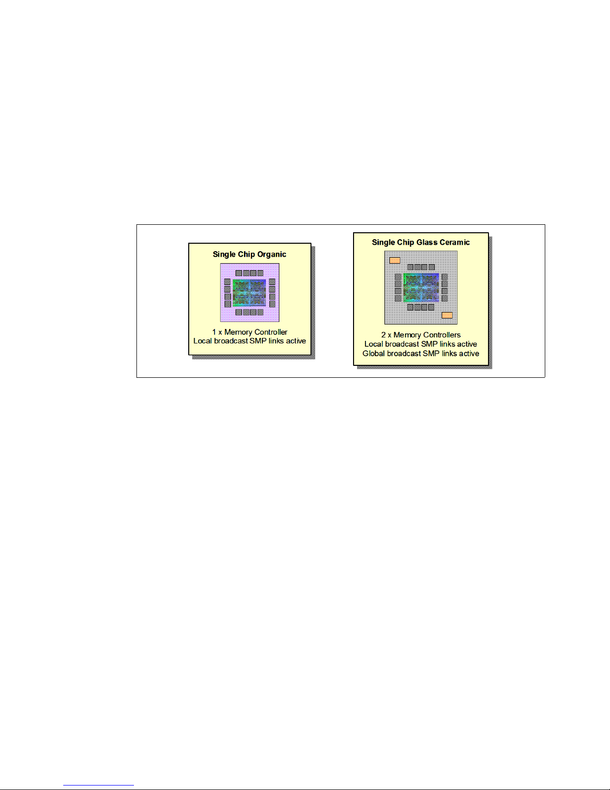
Optimized for servers
The POWER7 processor forms the basis of a flexible compute platform and can be offered in
a number of guises to address differing system requirements.
The POWER7 processor can be offered with a single active memory controller with four
channels for servers where higher degrees of memory parallelism are not required.
Similarly, the POWER7 processor can be offered with a variety of SMP bus capacities
appropriate to the scaling-point of particular server models.
Figure 2-6 shows the physical packaging options that are supported with POWER7
processors.
Figure 2-6 Outline of the POWER7 processor physical packaging
2.2.6 On-chip L3 intelligent cache
A breakthrough in material engineering and microprocessor fabrication has enabled IBM to
implement the L3 cache in eDRAM and place it on the POWER7 processor die. L3 cache is
critical to a balanced design, as is the ability to provide good signalling between the L3 cache
and other elements of the hierarchy, such as the L2 cache or SMP interconnect.
The on-chip L3 cache is organized into separate areas with differing latency characteristics.
Each processor core is associated with a Fast Local Region of L3 cache (FLR-L3) but also
has access to other L3 cache regions as shared L3 cache. Additionally, each core can
negotiate to use the FLR-L3 cache associated with another core, depending on reference
patterns. Data can also be cloned to be stored in more than one core's FLR-L3 cache, again
depending on reference patterns. This
processor to optimize the access to L3 cache lines and minimize overall cache latencies.
intelligent cache management enables the POWER7
44 IBM BladeCenter PS703 and PS704 Technical Overview and Introduction
Page 59
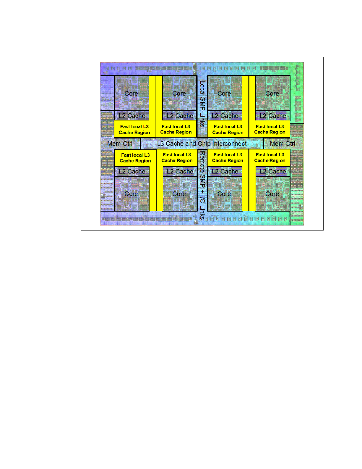
Figure 2-7 shows the FLR-L3 cache regions for the cores on the POWER7 processor die.
Figure 2-7 FLR-L3 cache regions on the POWER7 processor
The innovation of using eDRAM on the POWER7 processor die is significant for several
reasons:
Latency improvement
A six-to-one latency improvement occurs by moving the L3 cache on-chip compared to L3
accesses on an external (on-ceramic) ASIC.
Bandwidth improvement
A 2x bandwidth improvement occurs with on-chip interconnect. Frequency and bus sizes
are increased to and from each core.
No off-chip driver or receivers
Removing drivers and receivers from the L3 access path lowers interface requirements,
conserves energy, and lowers latency.
Small physical footprint
The performance of eDRAM when implemented on-chip is similar to conventional SRAM
but requires far less physical space. IBM on-chip eDRAM uses only a third of the
components used in conventional SRAM, which has a minimum of six transistors to
implement a 1-bit memory cell.
Low energy consumption
The on-chip eDRAM uses only 20% of the standby power of SRAM.
Chapter 2. Architecture and technical overview 45
Page 60

2.2.7 POWER7 processor and intelligent energy
Energy consumption is an important area of focus for the design of the POWER7 processor,
which includes intelligent energy features that help to optimize energy usage and
performance dynamically, so that the best possible balance is maintained. Intelligent energy
features (such as EnergyScale) work with the BladeCenter Advanced Management Module
(AMM) and IBM Systems Director Active Energy Manager™ to optimize processor speed
dynamically, based on thermal conditions and system use.
For more information about the POWER7 energy management features see the following
document:
Adaptive Energy Management Features of the POWER7 Processor
http://www.research.ibm.com/people/l/lefurgy/Publications/hotchips22_power7.pdf
TurboCore mode
Note: TurboCore mode is not available on the PS703 and PS704 blades.
TurboCore mode is a feature of the POWER7 processor but is not implemented in the PS703
and PS704 servers. It uses four cores per POWER7 processor chip with access to the entire
32 MB of L3 cache (8 MB per core) and at a faster processor core frequency, which delivers
higher performance per core, and might save on software costs for those applications that are
licensed per core.
2.2.8 Comparison of the POWER7 and POWER6 processors
Table 2-2 compares characteristics of various generations of POWER7 and POWER6
processors.
Note: This shows the characteristics of the POWER7 processors in general, but not
necessarily as implemented in the POWER7 processor-based blade servers.
Implementation specifics are noted.
Table 2-2 Comparison of technology for the POWER7 processor and the prior generation
Feature POWER7
(PS703, PS704)
Technology 45 nm 45 nm 65 nm 65 nm
Die size 567 mm
Maximum cores 8 8 2 2
Maximum SMT
threads per core
L2 Cache 256 KB per core 256 KB per core 4 MB per core 4 MB per core
L3 Cache 4 MB of FLR-L3 cache
4 threads 4 threads 2 threads 2 threads
per core with each core
having access to the full
32 MB of L3 cache,
on-chip eDRAM
2
POWER7
(PS700, PS701, PS702)
567 mm
4 MB of FLR-L3 cache
per core with each core
having access to the full
32 MB of L3 cache,
on-chip eDRAM
2
POWER6+ POWER6
341 mm
32 MB off-chip
eDRAM ASIC
2
341 mm
32 MB off-chip
eDRAM ASIC
2
46 IBM BladeCenter PS703 and PS704 Technical Overview and Introduction
Page 61

Feature POWER7
(PS703, PS704)
CPU frequency 2.4 GHz 3.0 GHz 5.0 GHz 4.2 GHz
Memory support DDR3 DDR3 DDR2 DDR2
POWER7
(PS700, PS701, PS702)
POWER6+ POWER6
I/O Bus Two GX++ Two GX++ (but operate
in GX+ mode)
Enhanced Cache
Mode (TurboCore)
Sleep & Nap Mode Both Both Nap only Nap only
No No No No
One GX+ One GX+
2.3 POWER7 processor-based blades
The PS703 and PS704 are follow-ons to the previous generation blades, the PS700, PS701
and PS702. The PS700 blade contains a single processor socket with a 4-core processor and
eight DDR3 memory DIMM slots. The PS701 blade contains a single processor socket with
an 8-core processor and 16 DDR3 memory DIMM slots. The PS702 blade, a double-wide
server, contains two processor sockets, each with an 8-core processor and a total of 32
DDR3 memory DIMM slots.
The PS703 blade contains two processor sockets, each with an 8-core processor and a total
of 16 DDR3 memory DIMM slots. The PS704 blade contains four processor sockets, each
with an 8-core processor and a total of 32 DDR3 memory DIMM slots. The cores in the
PS700, PS701, and PS702 blades run at 3.0 GHz. The cores in the PS703 and PS704
blades run at 2.4 GHz.
POWER7 processor-based blades support POWER7 processors with various processor core
counts. Table 2-3 summarizes the POWER7 processors for the PS700, PS701, PS702,
PS703, and PS704.
Table 2-3 Summary of POWER7 processor options for the PS700, PS701, PS702, PS703, and PS704 blades
Model Cores per
POWER7
processor
PS700 4 1 4 3.0 16
PS701 8 1 8 3.0 32
PS702 8 2 16 3.0 32
PS703 8 2 16 2.4 32
PS704 8 4 32 2.4 32
Number of
POWER7
processors
Tota l cores Frequency
(GHz)
L3 cache size
per POWER7
processor (MB)
2.4 Memory subsystem
Each POWER7 processor has two intergrated memory controllers in the chip. However, the
POWER7 blades only use one memory controller per processor and the second memory
controller of the processor is unused. The PS703’s two 8-core processors use a single
memory controller per processor, which connects to four memory buffers per CPU, providing
Chapter 2. Architecture and technical overview 47
Page 62
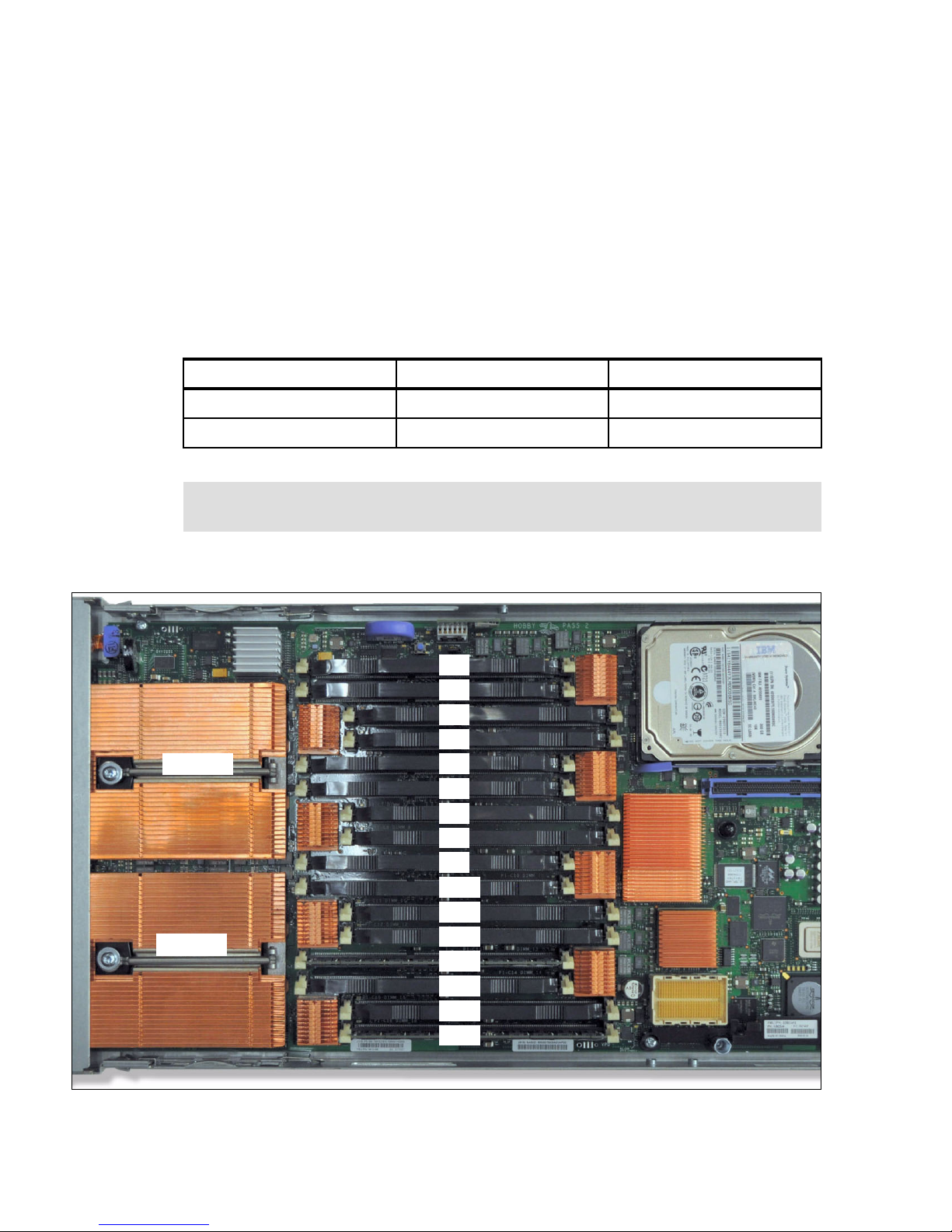
access to a total of 8 memory buffers and therefore 16 DDR3 DIMMS. The PS704’s four
1
2
3
4
5
6
7
8
9
10
11
12
13
14
15
16
CPU 0
CPU 1
8-core processor chips use a single memory controller per processor chip, which connects to
four memory buffers per CPU, providing access to a total of 16 memory buffers and therefore
32 DDR3 DIMMS.
Industry standard DDR3 Registered DIMM (RDIMM) technology is used to increase reliability,
speed, and density of memory subsystems.
2.4.1 Memory placement rules
The supported memory minimum and maximum for each server is listed in Table 2-4.
Table 2-4 Memory limits
Blade Minimum memory Maximum memory
PS703 16 GB 256 GB (16x 16 GB DIMMs)
PS704 32 GB 512 GB (32x 16 GB DIMMs)
Note: DDR2 memory (used in POWER6 processor-based systems) is not supported in
POWER7 processor-based systems.
Figure 2-9 shows the PS703 and PS704 physical memory DIMM topology.
Figure 2-8 Memory DIMM topology for the PS703 and PS704
48 IBM BladeCenter PS703 and PS704 Technical Overview and Introduction
Page 63
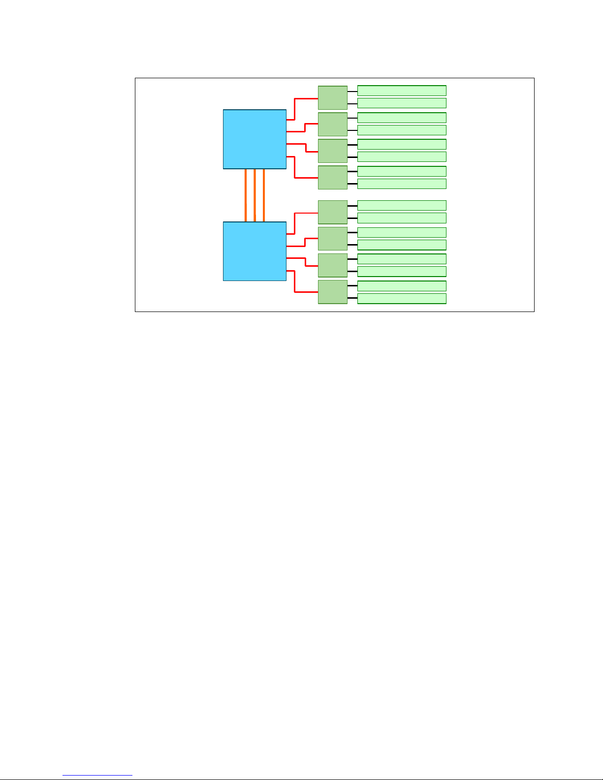
Figure 2-9 Memory DIMM topology
SMI
SMI
SMI
SMI
SMI
SMI
SMI
SMI
POWER7
Processor 1
POWER7
Processor 0
DIMM 1 (P1-C1)
DIMM 2 (P1-C2)
DIMM 3 (P1-C3)
DIMM 4 (P1-C4)
DIMM 5 (P1-C5)
DIMM 6 (P1-C6)
DIMM 7 (P1-C7)
DIMM 8 (P1-C8)
DIMM 9 (P1-C9)
DIMM 10 (P1-C10)
DIMM 11 (P1-C11)
DIMM 12 (P1-C12)
DIMM 13 (P1-C13)
DIMM 14 (P1-C14)
DIMM 15 (P1-C15)
DIMM 16 (P1-C16)
There are 16 buffered DIMM slots on the PS703 and PS704 base blade shown in Figure 2-9,
with an additional 16 slots on the PS704 expansion unit. The PS703 and the PS704 base
blade have slots labelled P1-C1 through P1-C16 as shown in Figure 2-9. For the PS704
expansion unit the numbering is the same except for the reference to the second planar
board. The numbering is from P2-C1 through P2-C16.
The memory-placement rules are as follows:
Install DIMM fillers in unused DIMM slots to ensure proper cooling.
Install DIMMs in pairs (1 and 4, 5 and 8, 9 and 12, 13 and 16, 2 and 3, 6 and 7, 10 and 11,
and 14 and 15).
Both DIMMs in a pair must be the same size, speed, type, and technology. You can mix
compatible DIMMs from different manufacturers.
Each DIMM within a processor-support group (1-4, 5-8, 9-12, 13-16) must be the same
size and speed.
Install only supported DIMMs, as described on the ServerProven web site. See:
http://www.ibm.com/servers/eserver/serverproven/compat/us/
DIMMs should be installed in specific DIMM sockets depending on the number of DIMMs to
install. This is described in the following tables. See Figure 2-9 for DIMM socket physical
layout compared to the DIMM location codes.
For the PS703, Table 2-5 shows the required placement of memory DIMMs depending on the
number of DIMMs installed.
Chapter 2. Architecture and technical overview 49
Page 64

Table 2-5 PS703 DIMM placement rules
DIMM
socket
number
DIMM
socket
location
code
PS703
Number of DIMMs to install
2 4 6 8 10 12 14 16
1P1-C1x x x x x x x x
2P1-C2
3P1-C3
4P1-C4
x x x x x x x x
5P1-C5
6P1-C6
7P1-C7
8P1-C8
9P1-C9
10 P1-C10
11 P1-C11
12 P1-C12
13 P1-C13
14 P1-C14
15 P1-C15
16 P1-C16
x x x x
x x x x
x x x x x x
x x
x x
x x x x x x
x x x x x x x
x x x
x x x
x x x x x x x
x x x x x
x
x
x x x x x
50 IBM BladeCenter PS703 and PS704 Technical Overview and Introduction
Page 65

For the PS704, Table 2-6 shows the required placement of memory DIMMs depending on the
number of DIMMs installed. The recommended practice is to match the DIMMs between the
two system planars.
Table 2-6 PS704 DIMM placement
DIMM
socket
number
1P1-C1
DIMM
socket
location
code
PS704
Number of DIMMs to install
4 8 12 16 20 24 28 32
x x x x x x x x
2P1-C2
3P1-C3
4P1-C4
5P1-C5
6P1-C6
7P1-C7
8P1-C8
9P1-C9
10 P1-C10
11 P1-C11
12 P1-C12
13 P1-C13
14 P1-C14
15 P1-C15
16 P1-C16
17 P2-C1
18 P2-C2
19 P2-C3
x x x x x x x x
x x x x x x x x
x x x x
x x x x
x x x x x x
x x
x x
x x x x x x
x x x x x x x
x x x
x x x
x x x x x x x
x x x x x
x
x
x x x x x
x x x x
x x x x
20 P2-C4
21 P2-C5
22 P2-C6
23 P2-C7
24 P2-C8
25 P2-C9
26 P2-C10
27 P2-C11
28 P2-C12
29 P2-C13
30 P2-C14
31 P2-C15
32 P2-C16
x x x x x x x x
x x x x x x
x x
x x
x x x x x x
x x x x x x x
x x x
x x x
x x x x x x x
x x x x x
x
x
x x x x x
Chapter 2. Architecture and technical overview 51
Page 66

2.5 Active Memory Expansion
% CPU
utilization
for
expansion
Amount of memory expansion
1 = Plenty of spare
CPU resource available
2 = Constrained CPU
resource –already
running at s ignificant
utilization
1
2
Very cost effective
Optional Active Memory Expansion is a POWER7 technology that allows the effective
maximum memory capacity to be much larger than the true physical memory. Innovative
compression/decompression of memory content using processor cycles can allow memory
expansion up to 100%.
This can allow an AIX 6.1 or later partition to do significantly more work with the same
physical amount of memory, or a server to run more partitions and do more work with the
same physical amount of memory.
Active Memory Expansion uses CPU resources to compress/decompress the memory
contents. The trade off of memory capacity for processor cycles can be an excellent choice,
but the degree of expansion varies based on how compressible the memory content is, and it
also depends on having adequate spare CPU capacity available for this compression/
decompression. Tests in IBM laboratories using sample workloads showed excellent results
for many workloads in terms of memory expansion per additional CPU utilized. Other test
workloads had more modest results.
Clients have a great deal of control over Active Memory Expansion usage. Each individual
AIX partition can turn on or turn off Active Memory Expansion. Control parameters set the
amount of expansion desired in each partition to help control the amount of CPU used by the
Active Memory Expansion function. An IPL is required for the specific partition that is turning
memory expansion on or off. After being turned on, there are monitoring capabilities in
standard AIX performance tools such as lparstat, vmstat, topas, and svmon.
Figure 2-10 represents the percentage of CPU used to compress memory for two partitions
with various profiles. The green curve corresponds to a partition that has spare processing
power capacity, while the blue curve corresponds to a partition constrained in processing
power.
Figure 2-10 CPU usage versus memory expansion effectiveness
Both cases shows that there is a knee-of-curve relationship for CPU resources required for
memory expansion:
Busy processor cores do not have resources to spare for expansion.
The more memory expansion is done, the more CPU resource is required.
The knee varies depending on how compressible memory contents are. This demonstrates
the need for a case by case study of whether memory expansion can provide a positive return
on investment.
52 IBM BladeCenter PS703 and PS704 Technical Overview and Introduction
Page 67

To help you perform this study, a planning tool is included with AIX 6.1 Technology Level 4 or
later allowing you to sample actual workloads and estimate both how expandable the
partition's memory is and how much CPU resource is needed. Any model Power System can
run the planning tool.
Figure 2-11 shows an example of the output returned by this planning tool. The tool outputs
various real memory and CPU resource combinations to achieve the desired effective
memory and indicates one particular combination. In this example, the tool proposes to
allocate 58% of a processor core, to benefit from 45% extra memory capacity.
Active Memory Expansion Modeled Statistics:
----------------------Modeled Expanded Memory Size : 8.00 GB
Expansion True Memory Modeled Memory CPU Usage
Factor Modeled Size Gain Estimate
--------- -------------- ----------------- -----------
1.21 6.75 GB 1.25 GB [ 19%] 0.00
1.31 6.25 GB 1.75 GB [ 28%] 0.20
1.41 5.75 GB 2.25 GB [ 39%] 0.35
1.51 5.50 GB 2.50 GB [ 45%] 0.58
1.61 5.00 GB 3.00 GB [ 60%] 1.46
Active Memory Expansion Recommendation:
--------------------The recommended AME configuration for this workload is to configure the LPAR with a
memory size of 5.50 GB and to configure a memory expansion factor of 1.51. This will
result in a memory expansion of 45% from the LPAR's current memory size. With this
configuration, the estimated CPU usage due to Active Memory Expansion is approximately
0.58 physical processors, and the estimated overall peak CPU resource required for the
LPAR is 3.72 physical processors.
Figure 2-11 Output form Active Memory Expansion planning tool
For more information on this topic see the white paper, Active Memory Expansion: Overview
and Usage Guide, available from:
http://www.ibm.com/systems/power/hardware/whitepapers/am_exp.html
Chapter 2. Architecture and technical overview 53
Page 68

2.6 Technical comparison
Table 2-7 shows a comparison of the technical characteristics of the PS700, PS701, PS702,
PS703, and PS704.
Table 2-7 Comparison of technical characteristics between PS700, PS701, PS702, PS703, and PS704
Systems characteristic PS700 PS701 PS702 PS703 PS704
Single Wide (SW) or
Double Wide (DW)
Processor 4-cores at
L3 cache 4 MB On-chip
Memory buffers 2 4 8 8 16
DIMM slots 8 16 32 16 32
DIMM speed 1066 MHz 1066 MHz 1066 MHz 1066 MHz 1066 MHz
Max Mem/core 16 GB 16 GB 16 GB 8 GB 8 GB
Anchor SVPD card 1 1 1 1 1
GX generation GX+ GX+ GX+ GX++ GX++
GX speed/BW 1.25GHz@4B
PCIe Gen1 support Yes Yes Yes No No
PCIe Gen2 support No No No Yes Yes
PCI-X support No No No No No
SW SW DW SW DW
3.0 GHz
eDRAM per
core
= 5Gb/s
8-cores at
3.0 GHz
4 MB On-chip
eDRAM per
core
1.25GHz@4B
= 5Gb/s
16-cores at
3.0 GHz
4 MB On-chip
eDRAM per
core
1.25GHz@4B
= 5Gb/s
16-cores at
2.4 GHz
4 MB On-chip
eDRAM per
core
2.5GHz@4B
= 10Gb/s
32-cores at
2.4 GHz
4 MB On-chip
eDRAM per
core
2.5GHz@4B
= 10Gb/s
Integrated 1 Gb Ethernet ports 2x HEA 2x HEA 4x HEA 2x
BCM5709S
I/O Hub 1 P5IOC2 1 P5IOC2 2 P5IOC2 1 P7IOC 2 P7IOC
Embedded SAS controller 1 1 1 1 1
2.5” SAS HDD option 2 1 2 1 2
SSD option No support No support No support 2x 1.8” SATA 4x 1.8” SATA
RAID function 0, 10 0 0, 10 0, 10 0, 10, 5, 6
BCM5387 5-port Ethernet
switch
CIOv slot 1 1212
CFFh slot 1 1212
1 1212
4x
BCM5709S
54 IBM BladeCenter PS703 and PS704 Technical Overview and Introduction
Page 69

2.7 Internal I/O subsystem
Two x8 Gen2
x8 Gen1
HDD/SSD connector
To chassis
I/O bays
1 & 2
To
media
tray
x1 Gen1
x4 Gen1
USB
controller
x8 Gen2
CIOv I/O con nector
3Gb
SAS
GX++ bus
CFFh I/O connector
PCIe to
PCI
P7IOC
I/O hub
To processor 0
BCM5387
Ethernet
switch
BCM5709
Gigabit
Ethernet
SAS passthrough
Each POWER7 processor as implemented in the PS703 and PS704 blades utilizes a single
GX++ bus from CPU0 to connect to the I/O subsystem as shown in Figure 2-12. The I/O
subsystem is a GX++ multifunctional host bridge ASIC chip (“P7IOC” in Figure 2-12). The
GX++ IO hub chip connects 6 PCIe ports, which provide access to the following devices:
GX++ primary interface to the processor
BCM5709S internal Ethernet controller
USB controller
CIOv card slot
Embedded 3Gb SAS controller
CFFh card slot
Note: Table 2-2 on page 46 indicates there are two GX buses in the POWER7 processor;
however, only one of them is active in the PS700, PS701, and PS703, and each planar in
the PS702 and PS704.
Figure 2-12 PS703 I/O Hub subsystem architecture
Figure 2-13 on page 56 shows the architecture of the I/O hub subsystem in the PS704 server,
showing the base planar and SMP planar. The PS704 with four POWER7 processors has two
GX++ multifunctional host bridge chips, one on each planar. The I/O system of the two hubs
is duplicated on both planars except for the embedded SAS controller and the USB controller.
The PS704 has only one embedded 3Gb SAS controller located on the SMP planar that
connects to both disk bays and CIOv card slots of the planars. When a CIOv SAS
Pass-through card is used on the base planar the embedded SAS controller also connects to
the ports of that card as well as the CIOv slot in the SMP planar. There is only one USB
controller located on the base planar as depicted in the diagram.
Chapter 2. Architecture and technical overview 55
Page 70

Figure 2-13 PS704 I/O Hub subsystem architecture
Two x8 Gen2
x8 Gen1
HDD/SSD connector
To chassis
I/O bays
1 & 2
x4 Gen1
x8 Gen2
CIOv I/O connector
GX++ bus
CFFh I/O connector
P7IOC
I/O hub
To processor 0
SAS pass-through
Two x8 Gen2
To chassis
I/O bays
1 & 2
To
media
tray
x1 Gen1
x4 Gen1
USB
controller
x8 Gen2
GX++ bus
CFFh I/O connector
PCIe to
PCI
P7IOC
I/O hub
To processor 0
BCM5387
Ethernet
switch
BCM5709
Gigabit
Ethernet
SAS pass-through
3Gb
SAS
HDD/SSD connector
CIOv I/O connector
PS704
base
planar
PS704
SMP
planar
BCM5709
Gigabit
Ethernet
2.7.1 PCI Express bus
PCIe uses a serial interface and allows for point-to-point interconnections between devices
using a directly wired interface between these connection points. A single PCIe serial link is a
dual-simplex connection using two pairs of wires, one pair for transmit and one pair for
2.7.2 PCIe slots
56 IBM BladeCenter PS703 and PS704 Technical Overview and Introduction
receive, and can only transmit one bit per cycle. It can transmit at the extremely high speed of
5 Gbps. These two pairs of wires is called a lane. A PCIe link might be comprised of multiple
lanes. In such configurations, the connection is labeled as x1, x2, x8, x12, x16, or x32, where
the number is the number of lanes.
The PCIe expansion card options for the PS700, PS701, PS702, PS703, and PS704 blades
support Extended Error Handling (EEH). The card ports are routed through the BladeCenter
mid-plane to predetermined I/O switch bays. The switches installed in these switch bays must
match the type of expansion card installed, Ethernet, Fibre Channel, and so forth.
The two PCIe slots are connected to the three x8 Gen2 PCIe links on the GX++
multifunctional host bridge chip. One of the x8 links supports the CIOv connector and the
other two links support the CFFh connector on the blade. All PCIe slots are Enhanced Error
Handling (EEH). PCI EEH-enabled adapters respond to a special data packet generated from
the affected PCIe slot hardware by calling system firmware, which examines the affected bus,
allows the device driver to reset it, and continues without a system reboot. For Linux, EEH
Page 71

support extends to the majority of frequently used devices, although various third-party PCI
devices might not provide native EEH support.
Expansion card form factors
There are two PCIe card form factors supported on the PS703 and PS704 blades:
CIOv
CFFh
CIOv form factor
A CIOv expansion card uses the PCI Express 2.0 x8 160 pin connector. A CIOv adapter
requires compatible switch modules to be installed in bay 3 and bay 4 of the BladeCenter
chassis. The CIOv card can be used in any BladeCenter that supports the PS703 and PS704
blades.
CFFh form factor
The CFFh expansion card attaches to the 450 pin PCIe Express connector of the blade
server. In addition, the CFFh adapter can only be used in servers that are installed in the
BladeCenter H, BladeCenter HT, or BladeCenter S chassis.
A CFFh adapter requires that either:
A Multi-Switch Interconnect Module (MSIM) or MSIM-HT (BladeCenter HT chassis) is
installed in bays 7 and 8, bays 9 and 10, or both.
A high speed switch module be installed in bay 7 and bay 9.
In the BladeCenter S, a compatible switch module is installed in bay 2.
The requirement of either the MSIM, MSIM-HT, or high-speed switch modules depends on
the type of CFFh expansion card installed. The MSIM or MSIM-HT must contain compatible
switch modules. See 1.7.6, “Multi-switch Interconnect Module” on page 33, or 1.7.7,
“Multi-switch Interconnect Module for BladeCenter HT” on page 34, for more information
about the MSIM or MSIM-HT.
The CIOv expansion card can be used in conjunction with a CFFh card in BladeCenter H, HT,
and in certain cases a BladeCenter S chassis, depending on the expansion card type.
Table 2-8 lists the slot types, locations, and supported expansion card form factor types of the
PS703 and PS704 blades.
Table 2-8 Slot configuration of the PS703 and PS704 blades
Card location Form factor PS703 location PS704 location
Base blade
Base blade
Expansion blade CIOv Not present
Expansion blade CFFh Not present
CIOv P1-C19 P1-C19
CFFh P1-C20 P1-C20
P2-C19
P2-C20
Chapter 2. Architecture and technical overview 57
Page 72

Figure 2-14 shows the locations of the PCIe CIOv and CFFh connectors, and the physical
CFFh connector - P1-C20 CIOv connector - P1-C19
CFFh connector - P1-C20 CIOv connector - P1-C19
location codes for the PS703.
Figure 2-14 PS703 location codes for PCIe expansion cards
Figure 2-15 shows the locations of the PCIe CIOv and CFFh connectors for the PS704 base
planar and the physical location codes. The expansion unit for the PS704 uses the prefix P2
for the slots on the second planar.
Figure 2-15 PS704 base location codes for PCIe expansion cards
58 IBM BladeCenter PS703 and PS704 Technical Overview and Introduction
Page 73
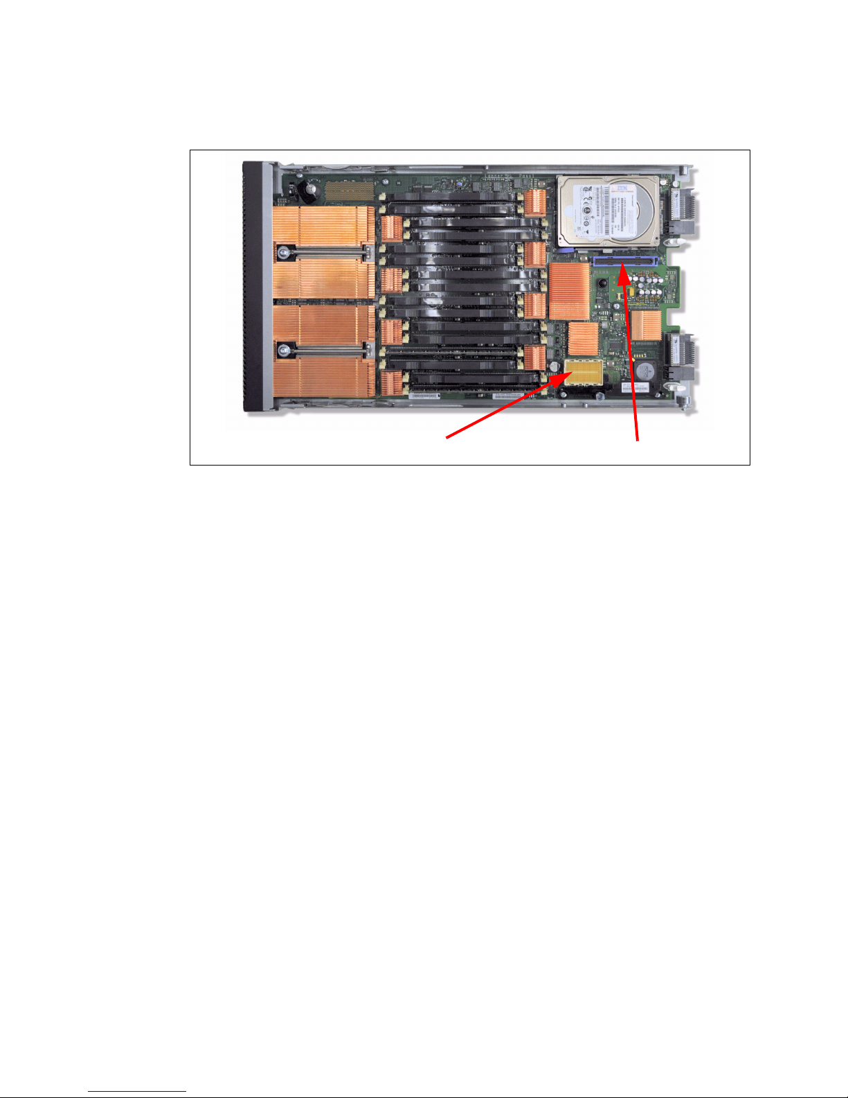
Figure 2-16 shows the locations of the PCIe CIOv and CFFh connectors for the PS702
CFFh connector - P2-C20 CIOv connector - P2-C19
expansion blade (feature code 8358) and the physical location codes.
Figure 2-16 PS704 expansion blade location codes for PCIe expansion cards
BladeCenter I/O topology
There are no externally accessible ports on the PS703 and PS704 blades; all I/O is routed
through a BladeCenter midplane to the I/O modules bays.
The I/O ports on all expansion cards are typically set up to provide a redundant pair of ports.
Each port has a separate path through the mid-plane of the BladeCenter chassis to a specific
I/O module bay. Figure 2-17 on page 60 through Figure 2-19 on page 61 show the supported
BladeCenter chassis and the I/O topology for each.
Chapter 2. Architecture and technical overview 59
Page 74
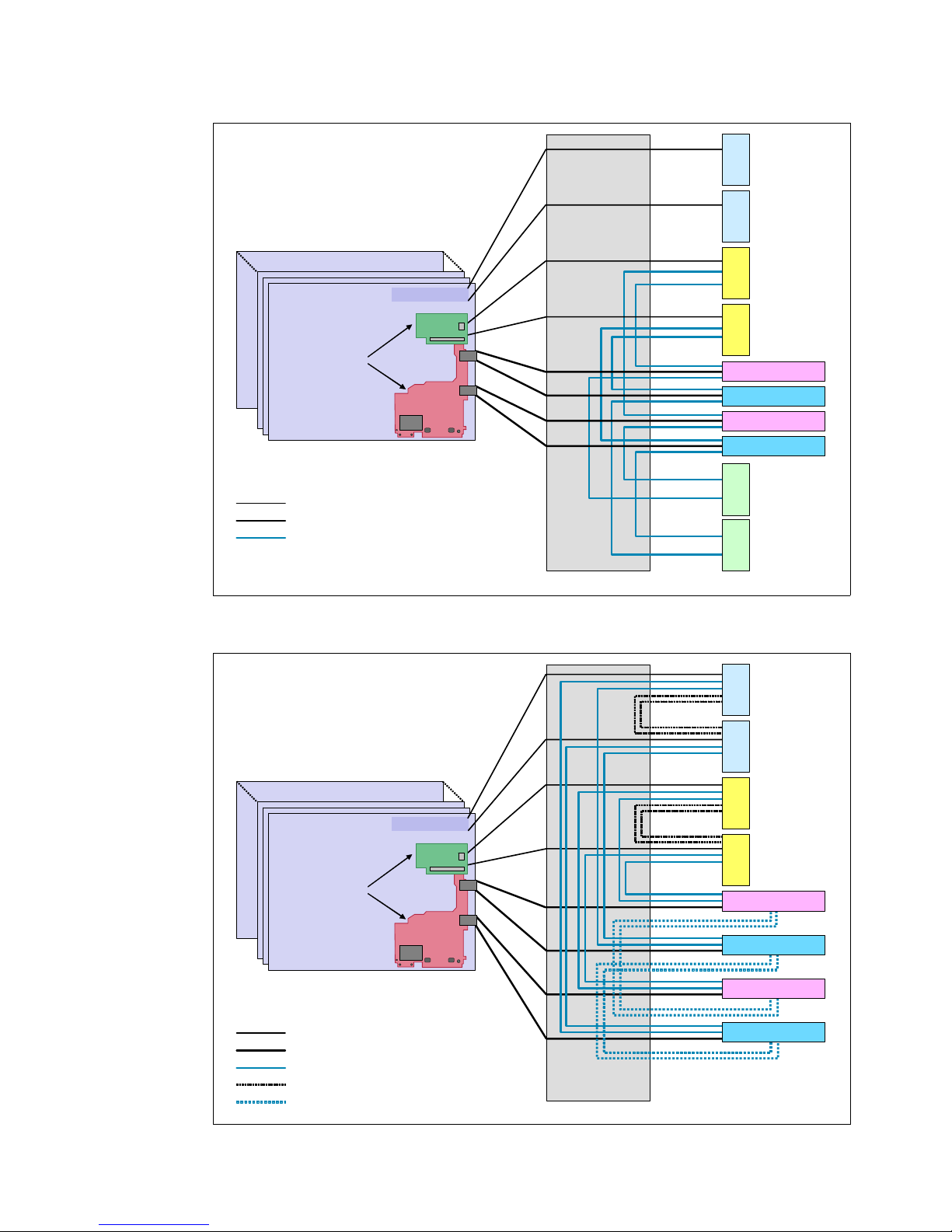
Blade Server 14
Blade Server 1
On-Board 1GbE
CFFv
CFFh
Expansion cards
I/O Bay 7
I/O Bay 9
I/O Bay 8
I/O Bay 10
I/O Bay 5I/O Bay 6 I/O Bay 3I/O Bay 4 I/O Bay 2
I/O Bay 1
Standard I/O bays connections
High-speed I/O bays c onnec tions
Bridge modules I/O ba ys connections
Legend
Mid-Plane
CIOv
Blade Server 12
Blade Server 1
On-Board 1GbE
CFFh
Expansion cards
Standard I/O bays connections
High-speed I/O bays c onnec tions
Bridge modules I/O ba ys connections
Standard I/O bays inter-switch links
High-speed I/O bays inter-switch links
Legend
Mid-Plane
I/O Bay 7
I/O Bay 8
I/O Bay 10
I/O Bay 9
I/O Bay 3I/O Bay 4 I/O Bay 2
I/O Bay 1
CIOv
Figure 2-17 BladeCenter H I/O topology
60 IBM BladeCenter PS703 and PS704 Technical Overview and Introduction
Figure 2-18 BladeCenter HT I/O topology
Page 75

2.7.3 I/O expansion cards
Blade Server 6
Blade Server 1 On-Boa rd 1G bE
CFFh
Expansion c ards
I/O Bay 3I/O Bay 4
I/O Ba y 1
Standard I/O bays connections
x4 SAS DSM connections
I/O bays 3 & 4 Ethernet connections
Legend
Mid-Plane
DSM1
DSM2
I/O Bay 2
CIOv
Figure 2-19 BladeCenter S I/O topology
I/O expansion cards can provide additional resources that can be used by a native operating
system, the Virtual I/O Server (VIOS), or assigned directly to a LPAR by the VIOS.
See 1.6.7, “I/O features” on page 21 for details about each supported card.
LAN adapters
In addition to the onboard 2-port Broadcom BCM5709S Ethernet controller, Ethernet ports
can be added with LAN expansion card adapters. The PS703 and PS704 support expansion
cards with Ethernet controllers as listed in Table 1-8 on page 21.
CIOv adapters require that Ethernet switches be installed in bays 3 and 4 of the BladeCenter
chassis.
CFFh expansion cards are supported in BladeCenter H and HT. The Broadcom 2/4-Port
Ethernet Expansion Card (CFFh) is also supported in the BladeCenter S. In the BC-H and
BC-HT, the CFFh adapters require that Ethernet switches be installed in bays 7 and 9, and
the Fibre Channel ports to switch bays 8 and 10. In the BladeCenter S only the Ethernet ports
are usable and the connection is to Bay 2.
SAS adapter
To connect to external SAS devices, including the BladeCenter S storage modules, the 3 Gb
SAS Passthrough Expansion Card and BladeCenter SAS Connectivity Modules are required.
Chapter 2. Architecture and technical overview 61
Page 76

The 3 Gb SAS Passthrough Expansion Card is a 2-port PCIe CIOv form factor card. The
IBM POWER7 blades each
with a Converged Network
Adapter
BNT Virtual Fabric
10Gb Switch Module
with 10Gb Ethernet
ports
QLogic Virtual Fabric
Extension Module with
8Gb Fibre Channel
ports
BladeCenter H
LAN
SAN
Internal
connections
output from the ports on this card is routed through the BladeCenter mid-plane to I/O switch
bays 3 and 4.
Fibre Channel adapters
The PS703 and PS704 blades support direct or SAN connection to devices using Fibre
Channel adapters and the appropriate pass-through or Fibre Channel switch modules in the
BladeCenter chassis. Fibre Channel expansion cards are available in both form factors and in
4 Gb and 8 Gb data rates.
The two ports on CIOv form factor expansion cards are connected to BladeCenter I/O switch
module bays 3 and 4. The two Fibre Channel ports on a CFFh expansion card connect to
BladeCenter H or HT I/O switch bays 8 and 10. The Fibre Channel ports on a CFFh form
factor adapter are not supported for use in a BladeCenter S chassis.
Fibre Channel over Ethernet (FCoE)
A new emerging protocol, Fibre Channel over Ethernet (FCoE), is being developed within T11
as part of the Fibre Channel Backbone 5 (FC-BB-5) project. It is not meant to displace or
replace FC. FCoE is an enhancement that expands FC into the Ethernet by combining two
leading-edge technologies (FC and Ethernet). This evolution of FCoE makes network
consolidation a reality; the combination of Fibre Channel and Ethernet enables a
consolidated network that maintains the resiliency, efficiency, and seamlessness of the
existing FC-based data center.
Figure 2-20 shows a configuration using BladeCenter FCoE components.
Figure 2-20 FCoE connections in IBM BladeCenter
For more information about FCoE, read An Introduction to Fibre Channel over Ethernet, and
Fibre Channel over Convergence Enhanced Ethernet, REDP-4493, available from the
following web page:
http://www.redbooks.ibm.com/abstracts/redp4493.html
The QLogic 2-port 10 Gb Converged Network Adapter is a CFFh form factor card. The ports
on this card are connected to BladeCenter H and HT I/O switch module bays 7 and 9. In
these bays a passthrough or FCoE-capable I/O module can provide connectivity to a
62 IBM BladeCenter PS703 and PS704 Technical Overview and Introduction
Page 77

top-of-rack switch. A combination of the appropriate I/O switch module in these bays and the
proper Fibre Channel-capable modules in bays 3 and 5 can eliminate the top-of-rack switch
requirement. See 1.7, “Supported BladeCenter I/O modules” on page 28.
InfiniBand Host Channel adapter
The InfiniBand Architecture (IBA) is an industry-standard architecture for server I/O and
interserver communication. It was developed by the InfiniBand Trade Association (IBTA) to
provide the levels of reliability, availability, performance, and scalability necessary for present
and future server systems with levels significantly better than can be achieved using
bus-oriented I/O structures.
InfiniBand is an open set of interconnected standards and specifications. The main InfiniBand
specification has been published by the InfiniBand Trade Association and is available at the
following web page:
http://www.infinibandta.org/
InfiniBand is based on a switched fabric architecture of serial point-to-point links. These
InfiniBand links can be connected to either host channel adapters (HCAs), used primarily in
servers, or target channel adapters (TCAs), used primarily in storage subsystems.
The InfiniBand physical connection consists of multiple byte lanes. Each individual byte lane
is a four-wire, 2.5, 5.0, or 10.0 Gbps bi-directional connection. Combinations of link width and
byte lane speed allow for overall link speeds of 2.5 - 120 Gbps. The architecture defines a
layered hardware protocol as well as a software layer to manage initialization and the
communication between devices. Each link can support multiple transport services for
reliability and multiple prioritized virtual communication channels.
For more information about InfiniBand, read HPC Clusters Using InfiniBand on IBM Power
Systems Servers, SG24-7767, available from the following web page:
http://www.redbooks.ibm.com/abstracts/sg247767.html
The 4X InfiniBand QDR Expansion Card is a 2-port CFFh form factor card and is only
supported in a BladeCenter H chassis. The two ports are connected to the BladeCenter H I/O
switch bays 7 and 8, and 9 and 10.
bays to route the traffic either between blade se rvers internal to the chassis or externally to an
InfiniBand fabric
.
2.7.4 Embedded SAS Controller
The embedded 3 Gb SAS controller is connected to one of the Gen1 PCIe x8 buses on the
GX++ multifunctional host bridge chip. The PS704 uses a single embedded SAS controller
located on the SMP expansion blade.
More information about the SAS I/O subsystem can be found in 2.9, “Internal storage” on
page 68.
2.7.5 Embedded Ethernet Controller
The Broadcom 2-port BCM5709S network controller has its own Gen1 x4 connection to the
GX++ multifunctional host bridge chip. The WOL, TOE, iSCSI, and RDMA functions of the
BCM5709S are not implemented on the PS703 and PS704 blades.
A supported InfiniBand switch is installed in the switch
The connections are routed through the 5-port Broadcom BCM5387 Ethernet switch ports 3
and 4. Then port 0 and port 1 of the BCM5387 connect to the Bladecenter chassis. Port 2 of
Chapter 2. Architecture and technical overview 63
Page 78

the BCM5387 is connected to the FSP to provide its connection to the chassis for SOL
connectivity.
See 2.8.1, “Server console access by SOL” on page 65 for more details concerning the SOL
connection.
Note: The PS703 and PS704 blades do not provide two Host Ethernet Adapters (HEA) as
the previous PS700, PS701, and PS703 blades did. This also means the Integrated Virtual
Ethernet (IVE) feature is not available on the PS703 and PS704 blades. Broadcom 5709S
Ethernet ports can be virtualized by PowerVM VIOS software.
MAC addresses for BCM5709S Ethernet ports
Each of the two BCM5709S Ethernet ports is assigned one physical MAC address. This is
different from the HEA, where each logical port of the HEA had its own MAC address. When
VIOS (Virtual IO System) is used on the PS703 or PS704 blades, it assigns the MAC virtual
address that corresponds to the BMC5709S physical addresses as appropriate. Thus the
total number of required MAC addresses for each PS703 and PS704 base planar is four, two
for FSP and two for Broadcom BCM5709S. On the PS704 SMP planar, only two MAC
addresses are needed for 5709S because there is no FSP.
Each planar has a label that lists the MAC addresses. The first two listed are those of FSP
enet0 and enet1 respectively. The next two listed are for BCM5709S port0 and port1
respectively.
2.7.6 Embedded USB controller
The USB controller complex is connected to the Gen1 PCIe x1 bus of the GX++
multifunctional host bridge chip as shown in Figure 2-1 on page 38.
This embedded USB controller provides support for four USB 2.0 root ports, which are routed
to the BladeCenter chassis midplane. However, only two are used:
Two USB ports are connected to the BladeCenter Media Tray, providing access to the
optical drive (if installed) and external USB ports to the blade server.
The other two ports are not connected. (On other servers, these USB connections are for
keyboard and mouse function, which the PS703 and PS704 blades do not implement.)
Note: The PS703 and PS704 blades do not support the KVM function from the AMM. If the
mouse and keyboard are plugged into the blade center, they are not operational with the
PS703 and PS704 blades. You must use SOL via the AMM or an SDMC virtual console to
connect to the blade. See 5.5.6, “Virtual consoles from the SDMC” on page 177 for more
details.
The BladeCenter Media Tray, depending on the BladeCenter chassis used, can contain up to
two USB ports, one optical drive and system status LEDs.
For information about the different media tray options available by BladeCenter model see
IBM BladeCenter Products and Technology, SG24-7523 available from:
http://www.redbooks.ibm.com/abstracts/sg247523.html
The media tray is a shared USB resource that can be assigned to any single blade slot at one
time, providing access to the chassis USB optical drive and USB ports.
64 IBM BladeCenter PS703 and PS704 Technical Overview and Introduction
Page 79

2.8 Service processor
The Flexible Service Processor (FSP) is used to monitor and manage the system hardware
resources and devices. In a POWER7-based blade implementation the external network
connection for the service processor is routed through an on-blade BCM5387 Ethernet
switch, through the BladeCenter midplane, chassis switches and to the AMM. The Serial over
LAN (SOL) connection for a system console uses this same connection. When the blade is in
standby power mode the service processor responds to AMM instructions and can detect
Wake-on-LAN (WOL) packets. The PS703 and PS704 blades have only one network port
available for configuring the service processor IP address in the AMM.
The PS703 has a single service processor. The PS704 has a second service processor in the
expansion unit. However, it is only used for controlling and managing the hardware on this
second planar.
2.8.1 Server console access by SOL
The PS703 and PS704 blades do not have an on-board video chip and do not support KVM
connections. Server console access is obtain by a SOL connection only. The AMM direct
KVM and remote control feature are not available to the PS703 and PS704 blades.
SOL provides a means to manage servers remotely by using a command-line interface (CLI)
over a Telnet or secure shell (SSH) connection. SOL is required to manage servers that do
not have KVM support or that are attached to an SDMC. SOL provides console redirection for
both System Management Services (SMS) and the blade server operating system. The SOL
feature redirects server serial-connection data over a LAN without requiring special cabling
by routing the data via the AMM network interface. The SOL connection enables blade
servers to be managed from any remote location with network access to the AMM.
SOL offers the following advantages:
Remote administration without keyboard, video, or mouse (headless servers)
Reduced cabling and no requirement for a serial concentrator
Standard Telnet interface, eliminating the requirement for special client software
The IBM BladeCenter AMM CLI provides access to the text-console command prompt on
each blade server through a SOL connection, enabling the blade servers to be managed from
a remote location.
In the BladeCenter environment, the SOL console data stream from a blade is routed from
the blade’s service processor to the AMM through the Ethernet switch on the blade's system
board. The signal is then routed through the netwo rk infr astructure o f the BladeCente r unit to
the Ethernet switch modules installed in bay 1 or 2.
Note: Link Aggregation is not supported with the SOL Ethernet port.
Figure 2-21 on page 66 shows the SOL traffic flow and the Gigabit Ethernet production traffic
flow.
Chapter 2. Architecture and technical overview 65
Page 80

Figure 2-21 SOL service processor to AMM connection
BCM5709
Gigabit
Ethernet
Ethernet switches
in chassis bays 1
and 2
BCM5387
Ethernet
switch
Phy
1Gb100Mb
CPU0 CPU1
FSP
P7IOC
I/O hub
External 1 Gb
Ethernet connections
(production network)
Advanced
Management
Module
(redundant pair)
External 100 Mb
Ethernet connections
(management
network)
Internal
management
network
SOL traffic
Production traffic
CPU 0
BladeCenter components are configured for SOL operation through the BladeCenter AMM.
The AMM also acts as a proxy in the network infrastructure to couple a client running a Telnet
or SSH session with the management module to an SOL session running on a blade server,
enabling the Telnet or SSH client to interact with the serial port of the blade server over the
network.
Because all SOL traffic is controlled by and routed through the AMM, administrators can
segregate the management traffic for the BladeCenter unit from the data traffic of the blade
servers. To start an SOL connection with a blade server, follow these steps:
1. Start a Telnet or SSH CLI session with the AMM.
2. Start a remote-console SOL session with any blade server in the BladeCenter unit that is
set up and enabled for SOL operation.
You can establish up to 20 separate web-interface, Telnet, or SSH sessions with a
BladeCenter AMM. For a BladeCenter unit, this step enables you to have 14 simultaneous
SOL sessions active (one for each of up to 14 blade servers) with six additional CLI sessions
available for BladeCenter unit management.
With a BladeCenter S unit you have six simultaneous SOL sessions active (one for each of
up to six blade servers) with 14 additional CLI sessions available for BladeCenter unit
management. If security is a concern, you can use Secure Shell (SSH) sessions, or
connections made through the serial management port that is available on the AMM, to
establish secure Telnet CLI sessions with the BladeCenter management module before
starting an SOL console-redirect session with a blade server.
SOL has the following requirements:
An Ethernet switch module or Intelligent Pass-Thru Module must be installed in bay 1 of a
BladeCenter (SOL does not operate with the I/O module in bay 2).
SOL must be enabled for those blades that you want to connect to with SOL.
66 IBM BladeCenter PS703 and PS704 Technical Overview and Introduction
Page 81
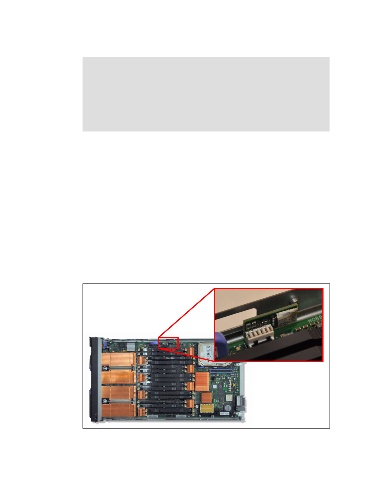
The Ethernet switch module must be set up correctly.
Anchor card
Note: The AMM has an option called management channel auto-discovery (MCAD) which
allows certain blades to dynamically change the path for the management network within
the chassis in order to use any IO module slot. The JS20, JS21, JS12, JS22, JS23, JS43,
PS700, PS701, PS702, PS703, and PS704 do not support the use of MCAD. You must
have a switch in IO module bay 1.
For more information about MCAD see the InfoCenter site at:
http://publib.boulder.ibm.com/infocenter/bladectr/documentation/index.jsp?topic
=/com.ibm.bladecenter.advmgtmod.doc/kp1bb_bc_mmug_usemcad.html
For details about setting up SOL, see the BladeCenter Serial Over LAN Setup Guide, which
can be found at the following web page:
http://ibm.com/support/entry/portal/docdisplay?lndocid=MIGR-54666
This guide contains an example of how to establish a Telnet or SSH connection to the
management module and then an SOL console.
2.8.2 Anchor card
The anchor card contains the Smart VPD chip that stores system-specific information. The
same anchor card is used for both the single-wide base blade and for the double-wide SMP
blade. The pluggable anchor card provides a means for the system-specific information to be
transferable from a faulty system planar to the replacement planar.
Before the service processor knows what system it resides on, it reads the SmartChip VPD to
obtain system information. There is only one anchor card for the PS703 and the PS704, as
shown in Figure 2-22. The PS704 base planar holds the anchor card; the SMP planar does
not have an anchor card.
Figure 2-22 Anchor card location
Chapter 2. Architecture and technical overview 67
Page 82

Note: The anchor card used in the PS700-PS704, unlike the card used in the JS series of
x8 Gen1
HDD/SSD connector
1x 2.5” HDD or
2x 1.8” SSDs
SAS Controller
Modules in bays 3 &
4 of the chassis
SAS Passthru card
(CIOv)
Bay 3Bay 4
P7IOC
I/O hub
3Gb
SAS
blades, does not contain LPAR or virtual server configuration data (such as CPU and
mmmemory allocations). When this card is swapped during a blade replacement operation
to the new blade the configuration information must be restored from a profile.bak file
generated on the old blade by the VIOS prior to the replacement. The command to
generate the profile.bak file is bkprofdata. The VIOS command to restore profile data is
rstprofdata. Generating a profile.bak should be part of good administrative practices for
POWER-based blades.
2.9 Internal storage
PS703 and PS704 blades use a single integrated 3 Gb SAS controller. The controller
attaches to the IO hub PCIe Gen1 connector operating at 2.5 Gbps. The PS704 has a single
embedded SAS controller located on the SMP planar. The PS704 base planar has no SAS
controller.
The PS703 blade embedded SAS controller provides a standard 2.5” connector for the
internal drive, and 2 ports through the CIOv connector to the optional 3 Gb SAS Passthrough
Expansion Card to the BladeCenter SAS switch modules. The SAS controller ports used for
the internal disk drives can support a single 2.5-inch SAS hard disk drive (HDD) or two
1.8-inch SATA solid state drives (SSD) via the SAS to SATA interposer card at each DASD
bay location, as shown in Figure 2-23.
Figure 2-23 PS703 SAS configuration
68 IBM BladeCenter PS703 and PS704 Technical Overview and Introduction
Page 83

Figure 2-24 shows the physical locations and codes for the HDDs in the PS703.
P1-D1 for SAS HDD
P1-C18 for Interposer
P1-C18-D1,2 for SSD1,2
SAS controller
Figure 2-24 HDD location and physical location code PS703
In the PS704 blade, the SAS controller is located on the SMP planar. A total of eight SAS
ports are used in the PS704 blade, four of which are used on the SMP planar and the other
four are routed from the SMP planar to the base planar. So for each planar of the PS704 there
are two ports for each DASD slot and two ports for each CIOv connector, as shown in
Figure 2-25.
Chapter 2. Architecture and technical overview 69
Page 84

x8 Gen1
P7IOC
I/O hub
HDD/SSD connector
SAS Controller
Modules in bays 3 and
4 of the chassis
SAS Passthru card
(CIOv)
Bay 3Bay 4
3Gb
SAS
HDD/SSD connector
or
or
Bay 3Bay 4
SAS Passthru card
(CIOv)
PS704
base
planar
PS704 SMP
planar
P1-D1 for SAS HDD
P1-C18 for Interposer
P1-C18-D1,2 for SSD1,2
Figure 2-25 PS704 SAS configuration
Figure 2-26 shows the physical location and code for a HDD in a PS704 base planar.
Figure 2-26 HDD location and physical location code PS704 base planar
70 IBM BladeCenter PS703 and PS704 Technical Overview and Introduction
Page 85

Figure 2-27 shows the physical location and code for a HDD in a PS704 SMP planar.
P2-D1 for SAS HDD
P2-C18 for Interposer
P2-C18-D1,2 for SSD1,2
SAS
Controller
Interposer without drives
Interposer with SSD partially installed
SSD with label up
Interposer with SSD fully installed
Figure 2-27 HDD location and physical location code PS704 SMP planar
Figure 2-28 shows the SATA SSD interposer card used to connect the 1.8-inch SATA SSD
drives to the drive bay.
Figure 2-28 SATA SSD Interposer card
Chapter 2. Architecture and technical overview 71
Page 86

Note: The SSDs used in the PS703 and PS704 servers are formatted in 528-byte sectors
and are only useable in RAID arrays or as hot spares. Each device contains metadata
written by the onboard 3Gb SAS controller to verify the RAID configuration. Error logs will
exist if problems are encountered. Refer to the appropriate service documentation should
errors occur.
2.9.1 Hardware RAID function
For the PS703, the supported RAID functions are as follows:
1 HDD - RAID 0
1 SSD - RAID 0
2 SSDs - RAID 0, 10
For the PS704, the supported RAID functions are as follows:
2 HDDs - RAID 0, 10
1 HDD and 1 SSD - RAID 0 on each disk (Combining HDD and SDD is not allowed in
other RAID configurations.)
2 SSDs - RAID 0, 10
3 SSDs - RAID 0, 5, 10 (RAID 10 on 2 disks; the third disk then can be a hot spare.)
4 SSDs - RAID 0, 5, 6, 10 (Hot spare with RAID 5 is possible, that is, 3 disks in RAID 5
and one disk as a hot spare.)
Drives in the PS703 or PS704 blade server can be used to implement and manage various
types of RAID arrays in operating systems that are on the ServerProven list. For the blade
server, you must configure the RAID array through the Disk Array Manager. The AIX Disk
Array Manager is packaged with the Diagnostics utilities on the Diagnostics CD for instances
when the operating system has not been installed yet. Use smit sasdam to use the AIX Disk
Array Manager to configure the disk drives for use with the SAS controller when there is an
operating system installed. The Disk Array Manager only provides the ability to configure
RAID 0, 5, 6 or 10. To achieve RAID1 mirror functionality use the RAID 10 option with two
internal disk drives.
You can configure a hot spare disk if there are enough disks available. A hot spare is a disk
that can be used by the controller to automatically replace a failed disk in a degraded RAID 5,
6, or 10 disk array. A hot spare disk is useful only if its capacity is greater than or equal to the
capacity of the smallest disk in an array that becomes degraded.
For more information about hot spare disks, see “Using hot spare disks” in the Systems
Hardware Information Center at:
http://publib.boulder.ibm.com/infocenter/powersys/v3r1m5/topic/arebj/sasusinghotsp
aredisks.htm
Note: Before you can create a RAID array, you must reformat the drives so that the sector
size of the drives changes from 512 bytes to 528 bytes. If you later decide to remove the
drives, delete the RAID array before you remove the drives. If you decide to delete the
RAID array and reuse the drives, you might need to reformat the drives so that the sector
size of the drives changes from 528 bytes to 512 bytes.
72 IBM BladeCenter PS703 and PS704 Technical Overview and Introduction
Page 87

For more information, see “Using the Disk Array Manager” in the Systems Hardware
Information Center at:
http://publib.boulder.ibm.com/infocenter/systems/scope/hw/index.jsp?topic=/arebj/s
asusingthesasdiskarraymanager.htm
2.9.2 External SAS connections
The onboard SAS controller in the PS703 and PS704 does not provide a direct access
external SAS port. However, by using a 3 Gb SAS Passthrough Expansion Card and
BladeCenter SAS Connectivity Modules, two ports on the SAS controller (four in the PS704
with a second SAS card on the expansion unit) are expanded, providing access to
BladeCenter S Disk Storage Modules (DSM) or an external SAS disk sub-system.
The Disk Storage Module, part number 43W3581 feature 4545 must be installed in the
BladeCenter S chassis to support external SAS storage devices outside the chassis using the
SAS Connectivity Card. No disk drives need to be installed in the DSM to support the external
storage.
Note: To also use external drives in a RAID array using the embedded SAS controller, the
drives must be formatted to 528 sectors.
2.10 External disk subsystems
This section describes the external disk subsystems that are supported IBM System Storage
family of products.
For up-to-date compatibility information for Power blades and IBM Storage, go to the Storage
System Interoperability Center at the following link:
http://ibm.com/systems/support/storage/config/ssic
For N Series Storage compatibility with Power blades, go to:
http://ibm.com/systems/storage/network/interophome.html
2.10.1 IBM BladeCenter S integrated storage
A key feature of the IBM BladeCenter S chassis is support for integrated storage. The
BladeCenter S supports up to two storage modules. These modules provide integrated SAS
storage functionality to the BladeCenter S chassis.
There are two ways to implement the integrated storage solution for BladeCenter S with the
PS703 and PS704:
Using the SAS Connectivity Module
Using the SAS RAID Controller Module
These methods are detailed in the following sections.
Basic local storage using SAS Connectivity Module
The main feature of basic local storage is the ability to assign physical disks in disk storage
modules (DSMs) to the blade server, and create volumes by using the RAID function of the
Chapter 2. Architecture and technical overview 73
Page 88

on-board SAS controller on the blade itself in conjunction with the SAS Passthrough Card
installed into the blade server.
Table 2-9 lists the basic local storage solution components for BladeCenter S.
Table 2-9 Basic local storage solution components for BladeCenter S
Component description Part number Min/max quantity
Disk Storage Module (DSM) 43W3581 1 / 2
SAS Connectivity Module 39Y9195 1 / 2
3 Gb SAS Passthrough Card (CIOv)
PS703 or PS704 7891 1 / 6
a. Also known as the SAS Connectivity Card (CIOv)
a
43W4068 1 per PS703
2 per PS704
Table 2-10 lists hard disk drives supported in DSMs by SAS Connectivity Modules.
Table 2-10 Hard disk drives supported in DSMs by SAS Connectivity Modules
Description Part number Max quantity
3.5” Hot Swap SATA
1000 GB Dual Port Hot Swap SATA HDD 43W7630 12 (6 per one DSM)
3.5” Hot Swap NL SAS
IBM 1 TB 7200 NL SAS 3.5'' HS HDD 42D0547 12 (6 per one DSM)
IBM 1 TB 7.2K 6 Gbps NL SAS 3.5'' HDD 42D0777 12 (6 per one DSM)
IBM 2 TB 7.2K 6 Gbps NL SAS 3.5'' HDD 42D0767 12 (6 per one DSM)
3.5” Hot Swap SAS
IBM 300 GB 15K 6 Gbps SAS 3.5" Hot-Swap HDD 44W2234 12 (6 per one DSM)
IBM 450 GB 15K 6 Gbps SAS 3.5" Hot-Swap HDD 44W2239 12 (6 per one DSM)
IBM 600 GB 15K 6 Gbps SAS 3.5" Hot-Swap HDD 44W2244 12 (6 per one DSM)
Figure 2-29 on page 75 shows a sample connection topology for basic local storage with one
SAS Connectivity Module installed.
74 IBM BladeCenter PS703 and PS704 Technical Overview and Introduction
Page 89

Mid-Plane
Blade Server 6
Blade Server 1
SAS Connectivity Card
Expansion card co nn ec t i ons
DSM connections
HDDs connections inside DSM
Legend
Disk Storage Module 1
Disk Storage Module 2
SAS Connectivity
Module (I/O bay 3)
Empty
(I/O bay 4)
CIOv
Mid-Plane
Blade Server 6
Blade Server 1
SAS Connectivity Card
Expansion card connections
DSM connections
HDDs connections inside DSM
Legend
Disk Storage Module 1
Disk Storage Module 2
SAS Connectivity
Module (I/O bay 3)
SAS Connectivity
Module (I/O bay 4)
CIOv
Figure 2-29 SAS I/O connections with one SAS Connectivity Module installed
Figure 2-30 shows a sample connection topology for basic local storage with two SAS
Connectivity Modules installed.
Figure 2-30 SAS I/O connections with two SAS Connectivity Modules installed
Chapter 2. Architecture and technical overview 75
Page 90

Keep the following considerations in mind when planning BladeCenter S basic local storage
implementations:
Every blade requiring integrated storage connectivity must have one SAS Connectivity
Card installed.
At least one DSM must be installed into the BladeCenter S chassis; a maximum of two
DSMs are supported in one chassis. The IBM BladeCenter S does not ship with any
DSMs as standard.
At least one SAS Connectivity Module must be installed into the BladeCenter S chassis. A
maximum of two SAS modules are supported for redundancy and high availability
purposes.
If two SAS connectivity modules are installed, the module in I/O module bay 3 controls
access to storage module 1, and the module in I/O module bay 4 controls access to
storage module 2.
Each physical hard disk drive in any DSM can be assigned to the one blade server only,
and the blade itself sees this physical disk (or disks) as its own hard disk drives connected
via SAS expansion card. That is, there are no LUNs, storage partitions, and so forth as in
shared storage systems. Instead, each blade has its own set of physical disks residing in
DSM (or DSMs).
The SAS Connectivity Module controls disk assignments by using zoning-like techniques,
which results in the SAS module maintaining single, isolated, dedicated paths between
physical HDDs and the blade server. Configuration of HDD assignments is done by the
administrator, and the administrator uses predefined templates or creates custom
configurations.
The RAID functionality is supplied by the onboard SAS controller when SAS Connectivity
Cards are used in the blade servers.
The maximum number of drives supported by the IM volume is two, plus one optional
global hot spare. The IME volume supports up to ten HDDs plus two optional hot spares.
The IS volume supports up to ten HDDs. The IS volume does not support hot spare
drives.
When creating a RAID-1 array, we recommend that you span both disk storage modules.
This maximizes the availability of data if one of the paths to the disks is lost, because there
is only one connection to each disk storage module, as shown in Figure 2-30 on page 75.
Mixing HDDs of different capacities in a single volume is supported. However, the total
volume size is aligned with the size of the smallest HDD, and excess space on
larger-sized HDDs is not used.
Supported combinations of volumes include:
– Two IM or IME volume per blade server
– One IM or IME volume and one IS volume per blade server
– Two IS volumes per blade server
Each blade with an SAS expansion card has access to its assigned HDDs in both DSMs,
even if only one SAS Connectivity module is present. Potentially, all 12 drives in both
DSMs can be assigned to the single blade server. However, only 10 HDDs can be used in
a single volume. You can create either two volumes to utilize the capacity of all drives, or
designate the remaining two drives as hot spares.
Both SAS and SATA hot swap HDDs are supported, and an intermix of SAS and SATA
drives is supported, as well. However, each volume must have hard disks of the same
type; that is, SAS or SATA.
External disk storage attachments are not supported.
76 IBM BladeCenter PS703 and PS704 Technical Overview and Introduction
Page 91

Advanced shared storage using the SAS RAID Controller Module
The main feature of advanced shared storage for BladeCenter S is the ability to:
Create storage pools from hard disks in disk storage modules
Create logical volumes in these pools
Assign these volumes rather than physical disks to the blade servers
Map a single logical volume to several blade servers simultaneously
Table 2-11 lists the advanced local storage components for BladeCenter S.
Table 2-11 Advanced local storage solution components for BladeCenter S
Component description Part number Min/max quantity
Disk Storage Module (DSM) 43W3581 1 / 2
SAS RAID Controller Module 43W3584 2 / 2
SAS Connectivity Card (CIOv) 43W4068 1 per PS703
2 per PS704
Ethernet Switch in I/O bay 1 Varies 1 / 1
PS703 or PS704 7891 1 / 6
Table 2-12 lists hard disk drives supported by SAS RAID Controller Modules.
Table 2-12 Hard disk drives supported in DSMs by SAS RAID Controller Modules
Description Part number Max quantity
3.5” Hot Swap NL SAS
IBM 1 TB 7200 NL SAS 3.5'' HS HDD 42D0547 12 (6 per one DSM)
IBM 1 TB 7.2K 6 Gbps NL SAS 3.5'' HDD 42D0777 12 (6 per one DSM)
IBM 2 TB 7.2K 6 Gbps NL SAS 3.5'' HDD 42D0767 12 (6 per one DSM)
3.5” Hot Swap SAS
IBM 300 GB 15K 6 Gbps SAS 3.5" Hot-Swap HDD 44W2234 12 (6 per one DSM)
IBM 450 GB 15K 6 Gbps SAS 3.5" Hot-Swap HDD 44W2239 12 (6 per one DSM)
IBM 600 GB 15K 6 Gbps SAS 3.5" Hot-Swap HDD 44W2244 12 (6 per one DSM)
Chapter 2. Architecture and technical overview 77
Page 92

Figure 2-31 shows a sample topology for BladeCenter S with two SAS RAID
Mid-Plane
Blade Server 6
Blade Server 1
SAS Connectivity Card
Expansion card connections
DSM connections
HDDs connections inside DSM
Legend
Disk Storage Module 1
SAS RAID Ctlr
Module (I/O bay 3)
SAS RAID Ctlr
Module (I/O bay 4)
Disk Storage Module 2
CIOv
Controller Modules.
Figure 2-31 BladeCenter S SAS RAID Controller connections topology
New features: Starting from firmware release 1.2.0, SAS RAID Controller Module now
supports online volume expansion, online storage pool expansion, concurrent code
update, and online DSM replacement for RAID-1 and 10 configurations. Prior to this
firmware level, the system must be stopped to perform capacity expansion, firmware
upgrade, or DSM servicing.
Keep these considerations in mind when planning BladeCenter S advanced shared storage
implementations:
Every blade requiring integrated storage connectivity must have one SAS Expansion Card
installed.
At least one DSM must be installed into the BladeCenter S chassis; a maximum of two
DSMs are supported in one chassis. The IBM BladeCenter S does not ship with any
DSMs as standard.
Two SAS RAID Controller Modules installed into the BladeCenter S chassis.
The SAS RAID Controller Module creates storage pools (or arrays), and the RAID level is
defined for these storage pools. Logical volumes are created from storage pools. Volumes
can be assigned to a specific blade, or can be shared by several blade servers.
Zoning is supported by the SAS RAID controller module. However, zoning should not be
used for regular operations (in other words, for purposes other than troubleshooting).
RAID functionality is supplied by the SAS RAID Controller Modules installed into the
BladeCenter S chassis.
78 IBM BladeCenter PS703 and PS704 Technical Overview and Introduction
– RAID levels supported: 0, 5, 6, 10.
– Maximum volume size is limited by size of storage pool.
Page 93

– Maximum number of volumes is 16 per blade server (maximum of 128 volumes per
chassis).
– One volume can be mapped to all 6 blades in the chassis.
Mixing HDDs of different capacities in a single volume is supported. However, the total
volume size is aligned with the size of the smallest HDD, and excess space on
larger-sized HDDs is not used.
Both SAS and Near-line SAS (NL SAS) hot swap HDDs are supported, and intermixing
SAS/NL SAS drives is supported as well. However, each storage pool must have hard
disks of the same type; that is, SAS or NL SAS. SATA drives are not supported by SAS
RAID Controller Module.
Global hot-spare drives are supported. The drive designated as a hot-spare should be as
large as, or larger than, other drives in the system.
Blade boot from logical volume is supported.
Path failover is supported with IBM Subsystem Device Driver Device Specific Module
(SDD DSM) for Windows® and Device Mapper Multipath (DMM) for Red Hat/Novell SUSE
Linux.
External tape attachments are supported.
For more information about the SAS RAID Controller solution, see:
SAS RAID Controller Installation and User Guide:
http://www.ibm.com/support/docview.wss?uid=psg1MIGR-5078040
SAS RAID Controller Module Interoperability Guide
http://www.ibm.com/support/docview.wss?uid=psg1MIGR-5078491
SAS RAID Controller Module Detailed Host Attachment Guide (Remote Boot included):
http://www.ibm.com/support/docview.wss?uid=psg1MIGR-5078491
2.10.2 IBM System Storage
The IBM System Storage Disk Systems products and offerings provide compelling storage
solutions with superior value for all levels of business.
IBM System Storage N series
IBM N series unified system storage solutions can provide customers with the latest
technology to help them improve performance, management, and system efficiency at a
reduced total cost of ownership. Several enhancements have been incorporated into the N
series product line to complement and reinvigorate this portfolio of solutions. The
enhancements include:
The new SnapManager® for Hyper-V provides extensive management for backup,
restoration, and replication for Microsoft® Hyper-V environments.
The new N series Software Packs provides the benefits of a broad set of N series
solutions at a reduced cost.
An essential component to this launch is Fibre Channel over Ethernet access and 10 Gb
Ethernet, to help integrate Fibre Channel and Ethernet flow into a unified network, and
take advantage of current Fibre Channel installations.
For more information, see the following web page:
http://www.ibm.com/systems/storage/network
Chapter 2. Architecture and technical overview 79
Page 94

IBM System Storage DS3000 family
The IBM System Storage DS3000 is an entry-level storage system designed to meet the
availability and consolidation needs for a wide range of users. New features, including larger
capacity 450 GB SAS drives, increased data protection features (such as RAID 6), and more
FlashCopy® images per volume provide a reliable virtualization platform with the support of
Microsoft Windows Server 2008 with HyperV.
For more information, see the following web page:
http://www.ibm.com/systems/storage/disk/ds3000/
IBM System Storage DS5020 Express
Optimized data management requires storage solutions with high data availability, strong
storage management capabilities, and powerful performance features. IBM offers the IBM
System Storage DS5020 Express, designed to provide lower total cost of ownership, high
performance, robust functionality, and unparalleled ease of use. As part of the IBM DS series,
the DS5020 Express offers the following features:
High-performance 8 Gbps capable Fibre Channel connections
Optional 1 Gbps iSCSI interface
Up to 112 TB of physical storage capacity with 112 1-TB SATA disk drives
Powerful system management, data management, and data protection features
For more information, see the following web page:
http://www.ibm.com/systems/storage/disk/ds5020/
IBM System Storage DS5000
New DS5000 enhancements help reduce costs by reducing power per performance by
introducing SSD drives. Also, with the new EXP5060 expansion unit supporting 60 1-TB
SATA drives in a 4 U package, you can see up to a one-third reduction in floor space over
standard enclosures. With the addition of 1 Gbps iSCSI host-attach, you can reduce cost for
less demanding applications and continue providing high performance where necessary by
using the 8 Gbps FC host ports. With DS5000, you get consistent performance from a
smarter design that simplifies your infrastructure, improves your total cost of ownership
(TCO), and reduces costs.
For more information, see the following web page:
http://www.ibm.com/systems/storage/disk/ds5000
IBM XIV Storage System
IBM is introducing a mid-sized configuration of its self-optimizing, self-healing, resilient disk
solution, the IBM XIV® Storage System. Organizations with mid-sized capacity requirements
can take advantage of the latest technology from IBM for their most demanding applications
with as little as 27 TB of usable capacity and incremental upgrades.
For more information, see the following web page:
http://www.ibm.com/systems/storage/disk/xiv/
IBM System Storage DS8700
The IBM System Storage DS8700 is the most advanced model in the IBM DS8000 lineup and
introduces dual IBM POWER6-based controllers that usher in a new level of performance for
the company’s flagship enterprise disk platform. The new DS8700 supports the most
demanding business applications with its superior data throughput, unparalleled resiliency
80 IBM BladeCenter PS703 and PS704 Technical Overview and Introduction
Page 95

features and five-nines availability. In today’s dynamic, global business environment, where
organizations need information to be reliably available around the clock and with minimal
delay, the DS8000 series can be an ideal solution. With its tremendous scalability, flexible
tiered storage options, broad server support, and support for advanced IBM duplication
technology, the DS8000 can help simplify the storage environment by consolidating multiple
storage systems onto a single system, and provide the availability and performance needed
for the most demanding business applications.
For more information, see the following web page:
http://www.ibm.com/systems/storage/disk/ds8000/
IBM Storwize V7000 Midrange Disk System
IBM Storwize V7000 is a virtualized storage system to complement virtualized server
environments that provides unmatched performance, availability, advanced functions, and
highly scalable capacity never seen before in midrange disk systems. IBM Storwize V7000 is
a powerful midrange disk system that is easy to use and enables rapid deployment without
additional resources. Storwize V7000 is virtual storage that offers greater efficiency and
flexibility through built-in SSD optimization and “thin provisioning” technologies. Storwize
V7000 advanced functions also enable non-disruptive migration of data from existing storage,
simplifying implementation, and minimizing disruption to users. IBM Storwize V7000 also
enables you to virtualize and reuse existing disk systems, supporting a greater potential
return on investment.
For more information, see the following web page:
http://www.ibm.com/systems/storage/disk/storwize_v7000/
2.11 IVM
IVM is a simplified hardware management solution that is part of the PowerVM
implementation on the PS703 and PS704 blades. POWER processor-based blades do not
include an option for attachment to a Hardware Management Console (HMC). POWER
processor-based blades do, however, include an option for attachment to an IBM Systems
Director Management Console (SDMC).
IVM inherits most of the HMC features and capabilities, and enables the exploitation of
PowerVM technology. It manages a single server, avoiding the need for an independent
appliance. It provides a solution that enables the administrator to reduce system setup time
and to make hardware management easier, at a lower cost.
IVM is an addition to the Virtual I/O Server, the product that enables I/O virtualization in the
family of POWER processor-based systems. The IVM functions are provided by software
executing within the Virtual I/O Server partition installed on the server. See Table 2-13.
For a complete description of the possibilities offered by IVM, see Integrated Virtualization
Manager on IBM System p5, REDP-4061, available the following web page:
http://www.redbooks.ibm.com/abstracts/redp4061.html
Chapter 2. Architecture and technical overview 81
Page 96

Table 2-13 Comparison of IVM, HMC, and SDMC
Characteristic IVM HMC SDMC
General characteristics
Delivery vehicle Integrated into the server A desktop or rack-mounted
Hardware/Software Appliance
appliance
Footprint Runs in 60 MB memory and
requires minimal CPU as it
runs stateless.
2-Core x86, 2 GB RAM, 80
GB HD
4-core CPU (Intel Nehalem or
better), 8 GB RAM, 500 GB
HD, 2 to 4 network interface
cards
Installation Installed with the Virtual I/O
Server (optical or network).
Preinstall option available on
certain systems.
Multiple system
One IVM per server One HMC can manage
support
Appliance is preinstalled.
Reinstall through optical
media or network is
supported.
multiple (non-blade) servers
(48 systems/ 1024 LPARS)
Hardware appliance is
preinstalled.
Software appliance requires
x86 to be installed on.
One SDMC can manage
multiple servers (48
systems/1024 virtual servers)
High-end servers Not supported Supported Supported (hardware
appliance only)
Low end &
Supported Supported Supported
midrange servers
Blade servers Supported Not Supported Supported
Server Families
Supported
P5, P5+: Yes
P6, P6+: Yes
P7: Yes
P5, P5+: Yes
P6, P6+: Yes
P7: Yes
P5, P5+: No
P6, P6+: Yes
P7: Yes
User interface Web browser (no local
Web browser (local or remote) Web browser (local or remote)
graphical display) and telnet
session
Scripting and
automation
VIOS command-line interface
(CLI) and HMC compatible
HMC CLI SMCLI
CLI.
RAS characteristics
Redundancy and
HA of manager
Only one IVM per server Multiple HMCs can manage
the same system for HMC
redundancy (active/active).
Multiple SDMCs can manage
the same system
(active/backup).
Multiple VIOS No, single VIOS Yes Yes
Fix or update
process for
VIOS fixes and updates HMC e-fixes and release
updates
Update Manager
manager
Adapter microcode
Inventory scout through RMC Inventory scout through RMC Update Manager
updates
82 IBM BladeCenter PS703 and PS704 Technical Overview and Introduction
Page 97

Characteristic IVM HMC SDMC
Firmware updates Inband through OS; not
concurrent
Serviceable event
management
PowerVM function
Full PowerVM
Capability
Capacity on
Demand
I/O Support for IBM iVirtual Only Virtual and Direct Virtual and Direct
Multiple Shared
Processor Pool
Workload
Management
(WLM) Groups
Supported
Support for multiple
profiles per partition
Service Focal Point Light:
Consolidated management of
firmware- and management
partition-detected errors
Partial Full Full
Entry of PowerVM codes only Full Support Full Support
No, default pool only Yes Yes
One 254 254
No Yes Yes
Service Focal Point™ with
concurrent firmware updates
Service Focal Point support
for consolidated management
of operating system- and
firmware-detected errors
Update Manager, concurrent
firmware updates
Service and Support Manager
for consolidated management
of operating system- and
firmware-detected errors
SysPlan Deploy &
mksysplan
Limited no POWER7 support,
no Deploy on blades
Yes Not in initial release, no blade
2.12 Operating system support
The IBM POWER7 processor-based systems support three families of operating systems:
AIX
IBM i
Linux
In addition, the Virtual I/O Server can be installed in special partitions that provide support to
the other operating systems for using features such as virtualized I/O devices, PowerVM Live
Partition Mobility, or PowerVM Active Memory Sharing.
Note: For details about the software available on IBM POWER servers, see Power
Systems Software™ at the following web page:
http://www.ibm.com/systems/power/software/
The PS703 and PS704 blades support the operating system versions identified in this
section.
support
Chapter 2. Architecture and technical overview 83
Page 98

Virtual I/O Server
Virtual I/O Server 2.2.0.12-FP24 SP02 or later
IBM regularly updates the Virtual I/O Server code. To find information about the latest
updates, see the Virtual I/O Server at the following web page:
http://www14.software.ibm.com/webapp/set2/sas/f/vios/documentation/home.html
IBM AIX Version 5.3
AIX Version 5.3 with the 5300-12 Technology Level with Service Pack 4 or later.
AIX Version 5.3 with the 5300-11 Technology Level with Service Pack 7 or later.
A partition using AIX Version 5.3 executes in POWER6 or POWER6+ compatibility mode.
IBM periodically releases maintenance packages (service packs or technology levels) for the
AIX 5L operating system. Information about these packages, downloading, and obtaining the
CD-ROM is on the Fix Central web page:
http://www.ibm.com/eserver/support/fixes/fixcentral/main/pseries/aix
The Service Update Management Assistant can help you to automate the task of checking
and downloading operating system downloads, and is part of the base operating system. For
more information about the suma command functionality, go to the following web page:
http://www14.software.ibm.com/webapp/set2/sas/f/genunix/suma.html
AIX Version 6.1
AIX 6.1 with the 6100-04 Technology Level with Service Pack 10 or later
AIX 6.1 with the 6100-05 Technology Level with Service Pack 6 or later
AIX 6.1 with the 6100-06 Technology Level with Service Pack 5 or later
For information regarding AIX V6.1 maintenance and support, go to the Fix Central web
page:
http://www.ibm.com/eserver/support/fixes/fixcentral/main/pseries/aix
AIX Version 7.1
AIX 7.1 with Service Pack 3 or later
For information regarding AIX V7.1 maintenance and support, go to the Fix Central web
page:
http://www.ibm.com/eserver/support/fixes/fixcentral/main/pseries/aix
IBM i
Virtual I/O Server is required to install IBM i in a LPAR on PS703 and PS704 blades and all
I/O must be virtualized.
IBM i 6.1 with i 6.1.1 machine code, or later
IBM i 7.1 or later
For a detailed guide on installing and operating IBM i with Power Blades, see the following
web page:
http://ibm.com/systems/resources/systems_power_hardware_blades_i_on_blade_readme.pdf
84 IBM BladeCenter PS703 and PS704 Technical Overview and Introduction
Page 99

Linux
Linux is an open source operating system that runs on numerous platforms from embedded
systems to mainframe computers. It provides a UNIX®-like implementation in many computer
architectures.
At the time of this writing, the supported versions of Linux on POWER7 processor technology
based servers are as follows:
SUSE Linux Enterprise Server 11 SP1 for POWER or later, with current maintenance
updates available from Novell to enable all planned functionality
Red Hat RHEL 5.6 for POWER, or later
Red Hat RHEL 6.0 for POWER, or later
Linux operating system licenses are ordered separately from the hardware. You can obtain
Linux operating system licenses from IBM, to be included with your POWER7 processor
technology-based servers, or from other Linux distributors.
Note: For systems ordered with the Linux operating system, IBM ships the most current
version available from the distributor. If you require a different version than that shipped by
IBM, you must obtain it via download from the Linux distributor's website. Information
concerning access to a distributor's website is located on the product registration card
delivered to you as part of your Linux operating system order.
For information about the features and external devices supported by Linux, go to the
following web page:
http://www.ibm.com/systems/p/os/linux/
For information about SUSE Linux Enterprise Server, go to the following web page:
http://www.novell.com/products/server
For information about Red Hat Enterprise Linux Advanced Server, go to the following web
page:
http://www.redhat.com/rhel/features
Supported virtualization features are listed in 3.4.10, “Supported PowerVM features by
operating system” on page 117.
Note: Users should also update their systems with the latest Linux for Power service and
productivity tools from IBM's website at
http://www14.software.ibm.com/webapp/set2/sas/f/lopdiags/home.html
2.13 IBM EnergyScale
IBM EnergyScale technology provides functions to help the user understand and dynamically
optimize the processor performance versus processor power and system workload, to control
IBM Power Systems power and cooling usage.
The BladeCenter AMM and IBM Systems Director Active Energy Manager exploit
EnergyScale technology, enabling advanced energy management features to conserve
power and improve energy efficiency. Intelligent energy optimization capabilities enable the
POWER7 processor to operate at a higher frequency for increased performance and
Chapter 2. Architecture and technical overview 85
Page 100

performance per watt, or reduce frequency to save energy. This feature is called
Tu rb o- Mo de .
Tip: Turbo-Mode, discussed here, and TurboCore mode, discussed in “TurboCore mode”
on page 46 are two different technologies.
2.13.1 IBM EnergyScale technology
This section describes IBM EnergyScale design features, and hardware and software
requirements.
IBM EnergyScale consists of the following elements:
A built-in EnergyScale device (formally known as Thermal Power Management Device or
TPMD).
Power executive software. IBM Systems Director Active Energy Manager, an IBM
Systems Directors plug-in and BladeCenter AMM.
IBM EnergyScale functions include the following elements:
Energy trending
EnergyScale provides continuous collection of real-time server energy consumption. This
function enables administrators to predict power consumption across their infrastructure
and to react to business and processing needs. For example, administrators might use
such information to predict data center energy consumption at various times of the day,
week, or month.
Thermal reporting
IBM Systems Director Active Energy Manager can display measured ambient temperature
and calculated exhaust heat index temperature. This information can help identify data
center hot spots that require attention.
Power Saver Mode
Power Saver Mode reduces the processor frequency and voltage by a fixed amount,
reducing the energy consumption of the system and still delivering predictable
performance. This percentage is predetermined to be within a safe operating limit and is
not user configurable. The server is designed for a fixed frequency drop of 50% from
nominal. Power Saver Mode is not supported during boot or reboot operations, although it
is a persistent condition that is sustained after the boot when the system starts executing
instructions.
Dynamic Power Saver Mode
Dynamic Power Saver Mode varies processor frequency and voltage based on the use of
the POWER7 processors. The user must configure this setting from the BladeCenter
AMM or IBM Director Active Energy Manager. Processor frequency and use are inversely
proportional for most workloads, implying that as the frequency of a processor increases,
its use decreases, given a constant workload.
Dynamic Power Saver Mode takes advantage of this relationship to detect opportunities to
save power, based on measured real-time system use. When a system is idle, the system
firmware lowers the frequency and voltage to Power Saver Mode values. When fully used,
the maximum frequency varies, depending on whether the user favors power savings or
system performance. If an administrator prefers energy savings and a system is
fully-used, the system can reduce the maximum frequency to 95% of nominal values. If
86 IBM BladeCenter PS703 and PS704 Technical Overview and Introduction
 Loading...