

Page 1

BladeCenter JS23
BladeCenter JS43
Type 7778
Installation and
User's Guide
Welcome.
Thank you for buying an
IBM blade server. This blade
server takes advantage of IBM
Power Architecture technologies
and features superior performance,
availability, and scalability.
This
contains information for setting up,
configuring, and using
your blade server.
Additionally, a service information
label is attached to each BladeCenter
unit and blade server. This label
provides a graphical summary of
many of the installation and service
activities that are associated with
each device.
Installation Guideand User's
Before installing the BladeCenter JS23 or JS43
Type 7778, you should have completed
the following procedures:
Installed and configured the rack according
to the documentation that came with the rack.
Installed and configured
into the rack. See the documentation provided
with the BladeCenter unit to install the unit
into the rack.
Supplied input power to the BladeCenter unit.
Install options in the blade server:
Drives
Memory modules
I/O expansion card
See Chapter 3 for more information.
Make sure that the BladeCenter management
module and the Ethernet switch module firmware
support the Serial over LAN (SOL) feature.
See the
Serial Over LAN Setup Guide
for more information.
Install the blade server in the BladeCenter unit.
See Chapter 3 for more information.
Establish an SOL session with the blade server. See the
Install the operating system.
See Chapter 5 for more information.
Install additional applications according to the
instructions provided with the applications.
the BladeCenter unit
for more information.Serial Over LAN Setup Guide
For more information about your
BladeCenter components and
features, view the publications
on the
IBM BladeCenter Documentation
CD or download the current publications
from the IBM Support Web site.
Go to http://www.ibm.com/systems/support/.
The blade server is now
ready to use. Be sure to
register and profile your
blade server on the
IBM support web site.
Page 2

Blade Server Support
Is the
blade server working
correctly?
Ye s
No
Check all cables for loose connections
and verify that all optional devices you
installed are on the ServerProven list at
http://www.ibm.com/servers/eserver/
serverproven/compat/us/.
Is the problem
solved?
Ye s
No
Register the blade server. Go to
http://www.ibm.com/support/mysupport/.
View information about IBM Support Line at
http://www.ibm.com/services/sl/products/
or view support telephone numbers at
http://www.ibm.com/planetwide/.
See the troubleshooting
information that comes with
the blade server to determine
the cause of the problem
and the action to take.
Is the problem
solved?
Ye s
No
Update the firmware to the
latest level.
You can download firmware from
http://www.ibm.com/systems/
support/.
Ye s
Is the problem
solved?
View support telephone numbers at
http://www.ibm.com/planetwide/.
Hardware
No Software
Hardware or
software problem?
Page 3

BladeCenter JS23 and BladeCenter JS43
Type 7778
Installation and User’s Guide
Page 4

Note
Before using this information and the product it supports, read the general information in
Appendix B, “Notices,” on page 65, the Warranty and Support Information document for your blade
server type and the IBM Environmental Notices and User Guide on the IBM Documentation CD.
Fourth Edition (May 2008)
© Copyright International Business Machines Corporation 2009.
US Government Users Restricted Rights – Use, duplication or disclosure restricted by GSA ADP Schedule Contract
with IBM Corp.
Page 5

Contents
Safety ...............v
Safety statements ............vi
Chapter 1. Product overview ......1
Related documentation ...........2
The IBM Documentation CD .........4
Hardware and software requirements .....4
Using the Documentation Browser ......4
Notices and statements in this documentation . . . 5
Features and specifications..........6
What your blade server offers ........8
Reliability, availability, and serviceability features . . 9
IBM Director ..............11
Chapter 2. Power, controls, indicators,
and connectors ...........13
Blade server control panel buttons and LEDs . . . 13
Turning on the blade server .........16
Turning off the blade server .........16
System-board layouts ...........17
System-board connectors .........17
System-board LEDs...........20
Chapter 3. Installing and removing
options ..............23
Installation guidelines ...........23
System reliability guidelines ........24
Handling static-sensitive devices ......24
Removing the blade server from a BladeCenter unit 25
Removing the blade server cover .......26
Removing the expansion unit ........27
Installing the expansion unit.........29
Removing a drive ............31
Installing a drive ............32
Removing a memory module ........33
Installing a memory module.........34
Supported DIMMs ............36
Removing and installing an I/O expansion card . . 37
Removing a CIOv form-factor expansion card . . 37
Installing a CIOv form-factor expansion card . . 39
Removing a combination-form-factor expansion
card................40
Installing a combination-form-factor expansion
card................41
Completing the installation .........42
Installing and closing the blade server cover . . 43
Installing the blade server in a BladeCenter unit 44
Input/output connectors and devices ......46
Chapter 4. Configuring the blade server 47
Updating the firmware ..........48
Starting the TEMP image .........49
Verifying the system firmware levels .....49
Using the SMS utility ...........50
Starting the SMS utility .........50
SMS utility menu choices .........50
Creating a CE login............51
Configuring the Gigabit Ethernet controllers . . . 51
Blade server Ethernet controller enumeration . . . 52
MAC addresses for host Ethernet adapters ....53
Updating IBM Director ..........54
Chapter 5. Installing the operating
system...............55
Locating the installation instructions ......56
Installing service and productivity tools for Linux
on POWER ..............57
Chapter 6. Solving problems .....59
Appendix A. Getting help and technical
assistance .............61
Before you call .............61
Using the documentation .........61
Getting help and information from the World
WideWeb..............62
Calling IBM for service ..........62
Software service and support ........63
Hardware service and support ........63
IBM Taiwan product service .........63
Appendix B. Notices .........65
Trademarks ..............66
Important notes .............66
Product recycling and disposal ........67
Battery return program ..........67
Electronic emission notices .........68
Federal Communications Commission (FCC)
statement ..............68
Industry Canada Class A emission compliance
statement ..............68
Avis de conformité à la réglementation
d’Industrie Canada ...........68
Australia and New Zealand Class A statement . 68
United Kingdom telecommunications safety
requirement .............69
European Union EMC Directive conformance
statement ..............69
Taiwanese Class A warning statement ....69
Chinese Class A warning statement .....70
Japanese Voluntary Control Council for
Interference (VCCI) statement .......70
Index ...............71
© Copyright IBM Corp. 2009 iii
Page 6

iv JS23/JS43 Type 7778: Installation and User’s Guide
Page 7

Safety
Before installing this product, read the Safety Information.
Antes de instalar este produto, leia as Informações de Segurança.
Pred instalací tohoto produktu si prectete prírucku bezpecnostních instrukcí.
Læs sikkerhedsforskrifterne, før du installerer dette produkt.
Lees voordat u dit product installeert eerst de veiligheidsvoorschriften.
Ennen kuin asennat tämän tuotteen, lue turvaohjeet kohdasta Safety Information.
Avant d’installer ce produit, lisez les consignes de sécurité.
Vor der Installation dieses Produkts die Sicherheitshinweise lesen.
Prima di installare questo prodotto, leggere le Informazioni sulla Sicurezza.
Les sikkerhetsinformasjonen (Safety Information) før du installerer dette produktet.
Antes de instalar este produto, leia as Informações sobre Segurança.
© Copyright IBM Corp. 2009 v
Page 8

Antes de instalar este producto, lea la información de seguridad.
Läs säkerhetsinformationen innan du installerar den här produkten.
Safety statements
Important: Each caution and danger statement in this documentation is labeled
with a number. This number is used to cross reference an English-language caution
or danger statement with translated versions of the caution or danger statement in
the Safety Information document.
For example, if a caution statement is labeled, ″Statement 1,″ translations for that
caution statement are in the Safety Information document under ″Statement 1.″ Be
sure to read all caution and danger statements in this documentation before you
perform the procedures. Read any additional safety information that comes with
your blade server or optional device before you install the device.
vi JS23/JS43 Type 7778: Installation and User’s Guide
Page 9

Statement 1
DANGER
Electrical current from power, telephone, and communication cables is
hazardous.
To avoid a shock hazard:
v Do not connect or disconnect any cables or perform installation,
maintenance, or reconfiguration of this product during an electrical storm.
v Connect all power cords to a properly wired and grounded electrical outlet.
v Connect to properly wired outlets any equipment that will be attached to
this product.
v When possible, use one hand only to connect or disconnect signal cables.
v Never turn on any equipment when there is evidence of fire, water, or
structural damage.
v Disconnect the attached power cords, telecommunications systems,
networks, and modems before you open the device covers, unless
instructed otherwise in the installation and configuration procedures.
v Connect and disconnect cables as described in the following table when
installing, moving, or opening covers on this product or attached devices.
To Connect: To Disconnect:
1. Turn everything OFF.
2. First, attach all cables to devices.
3. Attach signal cables to connectors.
4. Attach power cords to outlet.
5. Turn device ON.
1. Turn everything OFF.
2. First, remove power cords from outlet.
3. Remove signal cables from connectors.
4. Remove all cables from devices.
Safety vii
Page 10

Statement 2
CAUTION:
When replacing the lithium battery, use only IBM®Part Number 33F8354 or an
equivalent type battery recommended by the manufacturer. If your system has a
module containing a lithium battery, replace it only with the same module type
made by the same manufacturer. The battery contains lithium and can explode if
not properly used, handled, or disposed of.
Do not:
v Throw or immerse into water
v Heat to more than 100°C (212°F)
v Repair or disassemble
Dispose of the battery as required by local ordinances or regulations.
Statement 3
CAUTION:
When laser products (such as CD-ROMs, DVD drives, fiber optic devices, or
transmitters) are installed, note the following:
v Do not remove the covers. Removing the covers of the laser product could
result in exposure to hazardous laser radiation. There are no serviceable parts
inside the device.
v Use of controls or adjustments or performance of procedures other than those
specified herein might result in hazardous radiation exposure.
DANGER
Some laser products contain an embedded Class 3A or Class 3B laser diode.
Note the following.
Laser radiation when open. Do not stare into the beam, do not view directly
with optical instruments, and avoid direct exposure to the beam.
viii JS23/JS43 Type 7778: Installation and User’s Guide
Page 11

Statement 4
≥ 18 kg (39.7 lb) ≥ 32 kg (70.5 lb) ≥ 55 kg (121.2 lb)
CAUTION:
Use safe practices when lifting.
Statement 5
CAUTION:
The power control button on the device and the power switch on the power
supply do not turn off the electrical current supplied to the device. The device
also might have more than one power cord. To remove all electrical current from
the device, ensure that all power cords are disconnected from the power source.
1 2
Statement 8
Safety ix
Page 12

CAUTION:
Never remove the cover on a power supply or any part that has the following
label attached.
Hazardous voltage, current, and energy levels are present inside any component
that has this label attached. There are no serviceable parts inside these
components. If you suspect a problem with one of these parts, contact a service
technician.
Statement 10
CAUTION:
Do not place any object on top of rack-mounted devices.
x JS23/JS43 Type 7778: Installation and User’s Guide
Page 13

Chapter 1. Product overview
The IBM BladeCenter®JS23 blade server and JS43 blade server is based on IBM
Performance Optimization with Enhanced RISC (POWER®) Architecture
technologies. The BladeCenter JS23 blade server and JS43 blade server run in
BladeCenter units to provide a high-density, high-performance blade server
environment using advanced processing technology.
Note: Unless otherwise stated, references to the BladeCenter unit apply to
BladeCenter H (8852 and 7989), BladeCenter HT (8740 and 8750), and BladeCenter
S (8886 and 7779) units.
The Installation and User’s Guide comes with the blade server on the IBM
BladeCenter Documentation CD. All of the following information is in the document
and also in the online information center:
v Setting up the blade server
v Starting and configuring the blade server
v Installing optional hardware devices
v A reference to more information about installing supported operating systems
v Performing basic troubleshooting of the blade server
Packaged with the hardcopy Installation and User’s Guide are software CDs that
help you to configure hardware, install device drivers, and install the operating
system.
The blade server comes with a limited warranty. For information about the terms
of the warranty and getting service and assistance, see the online information
center or the Warranty and Support Information document that is on the IBM
BladeCenter Documentation CD.
The blade server might have features that are not described in the documentation
that comes with the blade server, and the documentation might be updated
occasionally to include information about those features, or technical updates
might be available to provide additional information that is not included in the
original blade server documentation. The most recent version of all BladeCenter
JS23 and JS43 documentation is in the BladeCenter information center.
The online BladeCenter information center is available in the IBM BladeCenter
Information Center at http://publib.boulder.ibm.com/infocenter/bladectr/
documentation/index.jsp.
Download and install updated device drivers and the JS23 aqnd JS43 firmware. Go
to the IBM Support site to download the updates. Select your product, type,
model, and operating system, and then click Go. Click the Download tab, if
necessary, for device driver and firmware updates.
Note: Changes are made periodically to the IBM Web site. Procedures for locating
firmware and documentation might vary slightly from what is described in this
documentation.
Print Table 1 on page 2 and use it to record information about your blade server.
© Copyright IBM Corp. 2009 1
Page 14

You will need this information when you register the blade server with IBM. You
can register the blade server at http://www.ibm.com/support/mysupport/.
Table 1 includes a place for you to record the JS23 and JS43 vital product data.
To determine the values for your JS23 blade server and JS43 blade server, use the
management module and the lsvpd command. If you are running Linux
®
,
download and install the service and productivity tools for Linux on POWER
systems to install the lsvpd command.
Table 1. JS23 and JS43 vital product data
Vital product data field Vital product data How to find this data
Product name BladeCenter JS23 and BladeCenter JS43
Type model number 7778-23X
Serial number
System unique ID
WorldWide port number
Brand B0 (B followed by zero)
________________________ (7 characters)
_________________________________ (12 characters)
_________________________________ (12 characters)
Advanced management
module HW VPD
Advanced management
module HW VPD
lsvpd | grep SU
command
lsvpd | grep WN
command
lsvpd | grep BR
command
The model number and serial number are on the ID label that is behind the control
panel door on the front of the blade server, and on a label on the side of the blade
server that is visible when the blade server is not in the BladeCenter unit.
A set of blank labels comes with the blade server. When you install the blade
server in the BladeCenter unit, write identifying information on a label and place
the label on the BladeCenter unit bezel. See the documentation for your
BladeCenter unit for recommended label placement.
Important: Do not place the label where it will block any ventilation holes on the
blade server or the BladeCenter unit.
Related documentation
Documentation for the JS23 and JS43 blade server includes documents in Portable
Document Format (PDF) on the IBM BladeCenter Documentation CD and the online
information center.
2 JS23/JS43 Type 7778: Installation and User’s Guide
Page 15

The most recent version of all BladeCenter documentation is in the BladeCenter
information center.
The online BladeCenter information center is available in the IBM BladeCenter
Information Center at http://publib.boulder.ibm.com/infocenter/bladectr/
documentation/index.jsp.
PDF versions of the following documents are on the IBM BladeCenter Documentation
CD and in the online information center:
v Problem Determination and Service Guide
This document contains information to help you solve problems yourself, and it
contains information for service technicians.
v Safety Information
This document contains translated caution and danger statements. Each caution
and danger statement that appears in the documentation has a number that you
can use to locate the corresponding statement in your language in the Safety
Information document.
v Warranty and Support Information
This document contains information about the terms of the warranty and about
getting service and assistance.
v BladeCenter Serial over LAN Setup Guide
This document explains how to update and configure BladeCenter components
for Serial over LAN (SOL) operation. The SOL connection provides access to the
text-based console command prompt on each blade server. Use SOL to manage
the blade servers from a remote location.
Additional documents might be included in the online information center and on
the IBM BladeCenter Documentation CD.
The blade server might have features that are not described in the documentation
that comes with the blade server. Occasional updates to the documentation might
include information about those features, or technical updates might be available
to provide additional information that is not included in the documentation that
comes with the blade server.
Review the online information or the Planning Guide and the Installation Guide for
your IBM BladeCenter unit. The information can help you prepare for system
installation and configuration. The most current version of each document is
available in the BladeCenter information center.
Chapter 1. Product overview 3
Page 16

The IBM Documentation CD
You can run the IBM BladeCenter Documentation CD on any personal computer that
meets the hardware and software requirements.
The IBM BladeCenter Documentation CD contains documentation for your blade
server in Portable Document Format (PDF) and includes the IBM Documentation
Browser to help you find information quickly.
Hardware and software requirements
The IBM BladeCenter Documentation CD requires the following minimum hardware
and software levels.
®
v Microsoft
v 100 MHz microprocessor
v 32 MB of RAM
v Adobe
systems
Windows®XP, Windows 2000, or Red Hat Linux
®
Acrobat Reader 3.0 (or later) or xpdf, which comes with Linux operating
Using the Documentation Browser
Use the Documentation Browser to browse the contents of the CD, read brief
descriptions of the documents, and view documents, using Adobe Acrobat Reader
or xpdf.
The Documentation Browser automatically detects the regional settings in your
system and displays the documents in the language for that region (if available). If
a document is not available in the language for that region, the English-language
version is displayed.
Use one of the following procedures to start the Documentation Browser:
v If Autostart is enabled, insert the CD into the CD or DVD drive. The
Documentation Browser starts automatically.
v If Autostart is disabled or is not enabled for all users, use one of the following
procedures:
– If you are using a Windows operating system, insert the CD into the CD or
DVD drive and click Start --> Run.IntheOpen field, type
e:\win32.bat
where e is the drive letter of the CD or DVD drive, and click OK.
– If you are using Red Hat Linux, insert the CD into the CD or DVD drive;
then, run the following command from the /mnt/cdrom directory:
sh runlinux.sh
Select the blade server from the Product menu. The Available Topics list displays
all the documents for the blade server. Some documents might be in folders. A
plus sign (+) indicates each folder or document that has additional documents
under it. Click the plus sign to display the additional documents.
When you select a document, a description of the document is displayed under
Topic Description. To select more than one document, press and hold the Ctrl key
while you select the documents. Click View Book to view the selected document
or documents in Acrobat Reader or xpdf. If you selected more than one document,
all the selected documents are opened in Acrobat Reader or xpdf.
4 JS23/JS43 Type 7778: Installation and User’s Guide
Page 17

To search all the documents, type a word or word string in the Search field and
click Search. The documents in which the word or word string occurs are listed in
order of the most occurrences. Click a document to view it, and press Crtl+F to use
the Acrobat search function, or press Alt+F to use the xpdf search function within
the document.
Click Help for detailed information about using the Documentation Browser.
Notices and statements in this documentation
The caution and danger statements in this document are also in the multilingual
Safety Information. Each statement is numbered for reference to the corresponding
statement in your language in the Safety Information document.
The following notices and statements are used in this document:
v Note: These notices provide important tips, guidance, or advice.
v Important: These notices provide information or advice that might help you
avoid inconvenient or problem situations.
v Attention: These notices indicate potential damage to programs, devices, or data.
An attention notice is placed just before the instruction or situation in which
damage might occur.
v Caution: These statements indicate situations that can be potentially hazardous
to you. A caution statement is placed just before the description of a potentially
hazardous procedure step or situation.
v Danger: These statements indicate situations that can be potentially lethal or
extremely hazardous to you. A danger statement is placed just before the
description of a potentially lethal or extremely hazardous procedure step or
situation.
Chapter 1. Product overview 5
Page 18

Features and specifications
Features and specifications of the IBM BladeCenter JS23 blade server and the JS43
blade server are summarized in this overview.
The JS23 and JS43 blade servers are available as a single-wide model (JS23 Type
7778-23X) and with a symmetric multi processing (SMP) planar expansion unit, as
a double-wide model (JS43 Type 7778-23X with feature code 8446). The JS23 blade
server and the JS43 blade server are used in an IBM BladeCenter H (8852 and
7989), BladeCenter HT (8740 and 8750), or BladeCenter S (8886 and 7779) chassis
unit.
Notes:
v Power, cooling, removable-media drives, external ports, and advanced system
management are provided by the BladeCenter unit.
v The operating system in the blade server must provide support for the Universal
Serial Bus (USB), to enable the blade server to recognize and communicate
internally with the removable-media drives and front-panel USB ports.
6 JS23/JS43 Type 7778: Installation and User’s Guide
Page 19

Core electronics:
64-bit Power 6+ processors (11S2
technology);
JS23 single-wide model:
v Dual core, dual socket (4-way)
processors @ 4.2 GHz (DCM)
v 64 GB maximum in 8 very low
profile (VLP) DIMM slots; Supports
2 GB, 4 GB, and 8 GB DDR2 VLP
DIMMs
v 1 internal small-form-factor (SFF)
Serial Attached SCSI (SAS) hard
drive or Solid State Drive (SSD)
JS43 double-wide model:
v Additional dual core, dual socket
(total 8-way) processors @ 4.2 GHz
(DCM)
v Additional 8 VLP DIMM slots for
total 128 GB maximum
v Additional 1 internal SFF SAS hard
drive or SSD
P5IOC2 I/O hub on-board, integrated
features:
v The baseboard management
controller (BMC) is a flexible
service processor (FSP1) with
Intelligent Platform Management
Interface (IPMI), Serial over LAN
(SOL), and Wake on LAN (WOL)
firmware support
v JS23: Two 1 GB Ethernet controllers
(HEA) connected to the
BladeCenter chassis fabric through
the 5-port integrated Ethernet
switch
v JS43: Two additional 1 GB Ethernet
controllers, connecting directly to
BladeCenter Ethernet switch
modules
v SAS RAID 0/1/5 controller
v 2D ATI Graphics (KVM support)
v USB 2.0
Daughter card I/O options:
v JS23: 1 1Xe expansion card: SFFv,
CFFv, or CIOv
v JS23: 1 PCIe High speed expansion
card - SFFh or CFFh
v JS43: Additional 1Xe connector
v JS43: Additional PCIe connector
Integrated functions:
v RS-485 interface for
communication with the
management module
v Automatic server restart (ASR)
v SOL through FSP
v Four Universal Serial Bus (USB
2.0) buses on base planar for
communication with keyboard
and removable-media drives
v Support for USB-attached local
keyboard, video, and mouse
(KVM)
v Transferable Anchor function
(Renesas Technology HD651330
microcontroller) in the
management card
v Optical media available by shared
chassis feature
Environment:
v Air temperature:
– Blade server on: 10° to 35°C
(50° to 95°F). Altitude: 0 to 914
m (3000 ft)
– Blade server on: 10° to 32°C
(50° to 90°F). Altitude: 914 m to
2133 m (3000 ft to 7000 ft)
– Blade server off: -40° to 60°C
(-40° to 140°F)
v Humidity:
– Blade server on: 8% to 80%
– Blade server off: 8% to 80%
JS23 Size:
v Height: 24.5 cm (9.7 inches)
v Depth: 44.6 cm (17.6 inches)
v Width: 30 mm (1.14 inches)
single-slot blade
v Maximum weight: 5.0 kg (11 lb)
JS43 Size:
v Height: 24.5 cm (9.7 inches)
v Depth: 44.6 cm (17.6 inches)
v Width: 60 mm (2.28 inches)
double-slot blade
v Maximum weight: 10.0 kg (22 lb)
Systems management:
v Supported by BladeCenter chassis
management module
v Front panel LEDs
v Light path diagnostics
v IBM Director
v Cluster Systems Management (CSM)
v Energy Scale thermal management
for power management/
oversubscription (throttling) and
environmental sensing
v IBM PowerExecutive
Clusters support for:
v eCluster 1350
v Cluster Systems Management
v High-performance computing (HPC)
Open Software Stack
Virtualization support for:
PowerVM
™
Standard Edition hardware
feature, which provides the Integrated
Virtualization Manager and Virtual
I/O Server
Partition Migration
Reliability and service features:
v Dual alternating current power
supply
v BladeCenter chassis redundant and
hot plug power and cooling
modules
v Predictive Failure Analysis
®
(PFA)
alerts for the microprocessor and
memory
v Boot-time processor deallocation
v Blade server hot plug
v Customer setup and expansion
v Automatic reboot on power loss
v Internal and ambient temperature
monitors
v ECC, chipkill memory
v System management alerts
Electrical input: 12Vdc
See the ServerProven Web site for information about supported operating-system
versions and all JS23 blade server and JS43 blade server optional devices.
Chapter 1. Product overview 7
Page 20

What your blade server offers
The design of the blade server takes advantage of advancements in chip
technology, memory management, and data storage.
The blade server uses the following features and technologies:
v Baseboard management controller (BMC)
The enhanced BMC for the JS23 blade server and JS43 blade server is a flexible
service processor that provides support for the following functions:
– Alert Standard Format (ASF) and RS-485 interfaces to the management
modules
– Intelligent Platform Management Interface (IPMI)
– The operating system
– Power control and advanced power management
– Reliability, availability, and serviceability (RAS) features
– Serial over LAN (SOL)
– Continuous health monitoring and control
– Configurable notification and alerts
– Event logs that are time stamped and saved in nonvolatile memory and that
can be attached to e-mail alerts
– Point-to-point protocol (PPP) support
– Remote power control
– Remote firmware update and access to critical blade server settings
v Disk drive support
The blade server supports one 2.5 inch (small-form-factor) Serial Attached SCSI
(SAS) hard disk drive.
v IBM Director
IBM Director is a workgroup-hardware-management tool that you can use to
centrally manage the JS23 blade server and JS43 blade server, including updating
the JS23 and JS43 firmware.
For more information, see the IBM Director documentation on the IBM Director
CD.
v Impressive performance using the latest microprocessor technology
The blade server comes with two POWER6
v Integrated network support
The blade server has two integrated (onboard) 1 gigabit-per-second (Gbps) Host
Ethernet Adapter (HEA) controllers that provide advanced acceleration features,
such as checksum offload, TCP large send, and jumbo frames. Capabilities
include virtualized adapter sharing among logical partitions that does not
require the shared Ethernet adapters of Virtual I/O Server. TCP advanced
features include hardware de-multiplexing and per connection queues.
v I/O expansion
The blade server has connectors on the system board for optional 1Xe and PCIe
expansion cards, such as Fibre Channel and InfiniBand expansion cards, for
adding more network communication capabilities to the blade server.
v Large system memory capacity
The memory bus in the JS23 Type 7778 blade server supports up to 64 GB of
system memory. The memory bus in the JS43 Type 7778 blade server supports
™
microprocessors.
8 JS23/JS43 Type 7778: Installation and User’s Guide
Page 21

up to 128 GB of system memory. For the official list of supported DIMMs, see
the ServerProven®Web site at http://www.ibm.com/servers/eserver/
serverproven/compat/us/.
v Light path diagnostics
Light path diagnostics provides light-emitting diodes (LEDs) to help you
diagnose problems. An LED on the blade server control panel is lit if an unusual
condition or a problem occurs. If this happens, you can look at the LEDs on the
system board to locate the source of the problem.
For more information, see the online information or the Problem Determination
and Service Guide.
v Power throttling
If your BladeCenter unit supports power management, the power consumption
of the blade server can be dynamically managed through the management
module. For more information, see the online management-module
documentation or the IBM support site at http://www.ibm.com/systems/
support/.
Reliability, availability, and serviceability features
Three of the most important features in server design are reliability, availability,
and serviceability (RAS). The reliability of the BladeCenter JS23 and the JS43 blade
servers starts with components, devices, and subsystems that are fault tolerant.
Reliability, availability, and serviceability protect the integrity of the data that is
stored in the blade server, maintain the availability of the blade server when you
need it, and enhance the ease with which you can diagnose and correct problems.
Component-level RAS features
The blade server has the following component-level RAS features:
v Alternate processor recovery
v Bit steering
v Chipkill
v Diagnostic support of Ethernet controllers
v Dual inline memory module (DIMM) failure isolation
– DIMM pair identification through unrecoverable error (UE) checkpointing and
– Single DIMM identification through recoverable component error (CE)
v Dynamic deallocation (runtime POWER6 garding of microprocessor and
memory)
v L2 cache line delete
v Memory chip kill - Chipkill memory for DIMMs
v Memory Predictive Failure Analysis (PFA) alerts through scrubbing and
error-checking and correction (ECC)
v Memory scrubbing
v Peripheral component interconnect (PCI) bus parity, ECRC, and surprise link
down
v PFA thresholding of correctable hardware errors of the microprocessors and L2
cache
v Processor runtime diagnostics (PRD) that initiates the following actions to
recover from errors:
– Self-healing, such as redundant bit steering for memory
– Deallocation at runtime of a failing resource, such as a processor core, a
™
memory for dual inline memory modules (DIMMs)
message-related recovery actions
checkpointing and garding
memory page
Chapter 1. Product overview 9
Page 22

– Identifying parts for service
– Runtime error persistent deallocation, if necessary, for I-Cash, D-cash, L2
cache, L3 cache
– Transparent microprocessor hardware error recovery (for example, for L2
cache errors)
v Single processor checkstop (including a partition checkstop)
Blade-level RAS features
The blade server has the following blade-level RAS features:
v Automatic service processor reset and reload recovery for service processor
errors
v Automatic server recovery and restart that provides automatic reboot after boot
hangs or detection of checkstop conditions
v Automatic server restart (ASR)
v Built-in monitoring for temperature, voltage, hard disk drives, and flash drives
v Call Home - eCare client
v Checkstop analysis
v Checkstop detection with automated restart
v Customer-upgradeable basic input/output system (BIOS) code (firmware code)
v Customer support center 24 hours per day, 7 days a week
v Degraded boot support (memory and microprocessors)
v Repeat Gard
v Extended Error Handling (EEH) for PCI host and root complex, PCIe link, and
PCI adapter failures
v Emergency power off (EPOW) for the blade server and expansion cards
v Environmental monitors and alerts
v Error codes and messages
v ECC memory
v Failover Ethernet support
v First Failure Data Capture (FFDC) for determining failure root cause
v Service processor communication with the management module to enable
remote blade server management
v Light emitting diodes (LEDs) for identifying failing customer replaceable units
(CRUs) or field replaceable units (FRUs)
v Light path diagnostics
v POWER6 RAS design and objectives
v POWER6 Hypervisor (PHYP) partition recovery or partition termination when
unrecoverable errors occur
v Power-on self-test (POST)
v SDRAM with serial presence detect (SPD) and vital product data (VPD)
v System error logging
v System Management Services (SMS) menu support
v System-wide checkstop
v Vital product data (VPD) unique identifiers on blade server and all major
electronic components with information stored in nonvolatile memory for remote
viewing
1
1. Service availability will vary by country. Response time will vary depending on the number and nature of incoming calls.
10 JS23/JS43 Type 7778: Installation and User’s Guide
Page 23

IBM Director
BladeCenter unit-level RAS features
The BladeCenter unit provides the following RAS features:
v Power-supply error detection
v Redundant power supplies
v Remote power control
v Management-module system-event log
v Redundant blowers, I/O modules (switches)
v Hot plug of BladeCenter CRUs (blowers, switches, power supplies)
Use IBM Director to perform network and system management tasks.
With IBM Director, a network administrator can perform the following tasks:
v View the hardware configuration of remote systems, in detail
v Monitor the usage and performance of critical components, such as
microprocessors, disks, and memory
v Centrally manage individual or large groups of IBM and non-IBM
x86-processor-based servers, desktop computers, workstations, and notebook
computers on a variety of platforms
IBM Director provides a comprehensive entry-level workgroup hardware manager.
It includes the following key features:
v Advanced self-management capabilities for maximum system availability.
v Multiple operating-system platform support, including Microsoft Windows
Server 2003, Windows 2000 Server, Windows XP Professional, Red Hat Linux,
SUSE Linux, VMware, Novell NetWare, AIX
(formerly known as i5/OS®). For a complete list of operating systems that
support IBM Director, see the IBM Director Compatibility Document. This
document is in Portable Document Format (PDF) at http://www.ibm.com/
systems/management/director/resources. It is updated every 6 to 8 weeks.
v Support for IBM and non-IBM servers, desktop computers, workstations, and
notebook computers.
v Support for systems-management industry standards.
v Integration into leading workgroup and enterprise systems-management
environments.
v Ease of use, training, and setup.
®
, and IBM i operating system
IBM Director also provides an extensible platform that supports advanced server
tools that are designed to reduce the total cost of managing and supporting
networked systems. By deploying IBM Director, you can achieve reductions in
ownership costs through the following benefits:
v Reduced downtime
v Increased productivity of IT personnel and users
v Reduced service and support costs
Chapter 1. Product overview 11
Page 24

12 JS23/JS43 Type 7778: Installation and User’s Guide
Page 25

Chapter 2. Power, controls, indicators, and connectors
You can use the control panel to turn the blade server on or off and to view some
controls and indicators. Other indicators are on the system board. The system
board also has connectors for various components.
Blade server control panel buttons and LEDs
Blade server control panel buttons and LEDs provide operational controls and
status indicators.
Note: Figure 1 shows the control-panel door in the closed (normal) position. To
access the power-control button, you must open the control-panel door.
Figure 1. Blade server control panel buttons and LEDs
© Copyright IBM Corp. 2009 13
Page 26

1 Keyboard/video select button: When you use an operating system that
supports a local console and keyboard, press this button to associate the shared
BladeCenter unit keyboard and video ports with the blade server.
Notes:
v The operating system in the blade server must provide USB support for the
blade server to recognize and use the keyboard, even if the keyboard has a
PS/2-style connector.
v The keyboard and video are available after partition firmware loads and is
running. Power-on self-test (POST) codes and diagnostics are not supported
using the keyboard and video. Use the management module to view
checkpoints.
The LED on this button flashes while the request is being processed, then is lit
when the ownership of the keyboard and video has been transferred to the blade
server. It can take approximately 20 seconds to switch control of the keyboard and
video to the blade server.
Using a keyboard that is directly attached to the management module, you can
press keys in the following sequence to switch keyboard and video control
between blade servers:
NumLock NumLock blade_server_number Enter
Where blade_server_number is the two-digit number for the blade bay in which
the blade server is installed. When you use some keyboards, such as the
28L3644 (37L0888) keyboard, hold down the Shift key while you enter this key
sequence.
If there is no response when you press the keyboard/video select button, you can
use the Web interface of the management module to determine whether local
control has been disabled on the blade server.
2 Media-tray select button: Press this button to associate the shared BladeCenter
unit media tray (removable-media drives and front-panel USB ports) with the
blade server. The LED on the button flashes while the request is being processed,
then is lit when the ownership of the media tray has been transferred to the blade
server. It can take approximately 20 seconds for the operating system in the blade
server to recognize the media tray.
If there is no response when you press the media-tray select button, use the
management module to determine whether local control has been disabled on the
blade server.
Note: The operating system in the blade server must provide USB support for the
blade server to recognize and use the removable-media drives and USB ports.
14 JS23/JS43 Type 7778: Installation and User’s Guide
Page 27

3 Information LED: When this amber LED is lit, it indicates that information
about a system error for the blade server has been placed in the
management-module event log. The information LED can be turned off through
the Web interface of the management module or through IBM Director Console.
4 Blade-error LED: When this amber LED is lit, it indicates that a system error
has occurred in the blade server. The blade-error LED will turn off after one of the
following events:
v Correcting the error
v Reseating the blade server in the BladeCenter unit
v Cycling the BladeCenter unit power
5 Power-control button: This button is behind the control panel door. Press this
button to turn on or turn off the blade server.
The power-control button has effect only if local power control is enabled for the
blade server. Local power control is enabled and disabled through the Web
interface of the management module.
Press the power button for 5 seconds to begin powering down the blade server.
6 NMI reset (recessed): The nonmaskable interrupt (NMI) reset dumps the
partition. Use this recessed button only as directed by IBM Support.
7 Sleep: This LED is not used in the JS blade family.
8 Power-on LED: This green LED indicates the power status of the blade server
in the following manner:
v Flashing rapidly: The service processor is initializing the blade server.
v Flashing slowly: The blade server has completed initialization and is waiting for
a power-on command.
v Lit continuously: The blade server has power and is turned on.
Note: The enhanced service processor can take as long as three minutes to
initialize after you install the BladeCenter JS23 or JS43 blade server, at which point
the LED begins to flash slowly.
9 Activity LED: When this green LED is lit, it indicates that there is activity on
the hard disk drive or network.
Chapter 2. Power, controls, indicators, and connectors 15
Page 28

10 Location LED: When this blue LED is lit, it has been turned on by the system
administrator to aid in visually locating the blade server. The location LED can be
turned off through the Web interface of the management module or through IBM
Director Console.
Turning on the blade server
After you connect the blade server to power through the BladeCenter unit, you can
start the blade server after the discovery and initialization process is complete.
You can start the blade server in any of the following ways.
v Start the blade server by pressing the power-control button on the front of the
blade server.
The power-control button is behind the control panel door, as described in
“Blade server control panel buttons and LEDs” on page 13.
After you push the power-control button, the power-on LED continues to blink
slowly for about 15 seconds, then is lit solidly when the power-on process is
complete.
Wait until the power-on LED on the blade server flashes slowly before you press
the blade server power-control button. If the power-on LED is flashing rapidly,
the service processor is initializing the blade server. The power-control button
does not respond during initialization.
Note: The enhanced service processor can take as long as three minutes to
initialize after you install the BladeCenter JS23 or JS43 blade server, at which
point the LED begins to flash slowly.
v Start the blade server automatically when power is restored after a power
failure.
If a power failure occurs, the BladeCenter unit and then the blade server can
start automatically when power is restored. You must configure the blade server
to restart through the management module.
v Start the blade server remotely using the management module.
After you initiate the power-on process, the power-on LED blinks slowly for
about 15 seconds, then is lit solidly when the power-on process is complete.
Turning off the blade server
When you turn off the blade server, it is still connected to power through the
BladeCenter unit. The blade server can respond to requests from the service
processor, such as a remote request to turn on the blade server. To remove all
power from the blade server, you must remove it from the BladeCenter unit.
16 JS23/JS43 Type 7778: Installation and User’s Guide
Page 29

Shut down the operating system before you turn off the blade server. See the
operating-system documentation for information about shutting down the
operating system.
You can turn off the blade server in one of the following ways.
v Turn off the blade server by pressing the power-control button for at least 5
seconds.
The power-control button is on the blade server behind the control panel door.
See “Blade server control panel buttons and LEDs” on page 13 for the location.
Note: The power-control LED can remain on solidly for up to 1 minute after
you push the power-control button. After you turn off the blade server, wait
until the power-control LED is blinking slowly before you press the
power-control button to turn on the blade server again.
If the operating system stops functioning, press and hold the power-control
button for more than 5 seconds to force the blade server to turn off.
v Use the management module to turn off the blade server.
The power-control LED can remain on solidly for up to 1 minute after you
initiate the power-off process. After you turn off the blade server, wait until the
power-control LED is blinking slowly before you initiate the power-on process
from the AMM to turn on the blade server again.
Use the management-module Web interface to configure the management
module to turn off the blade server if the system is not operating correctly.
For additional information, see the online documentation or the User’s Guide for
the management module.
System-board layouts
Illustrations show the connectors and LEDs on the system board. The illustrations
might differ slightly from your hardware.
System-board connectors
Blade server components attach to the connectors on the system board.
Figure 2 on page 18 shows the connectors on the base unit system board in the
blade server.
Chapter 2. Power, controls, indicators, and connectors 17
Page 30

Figure 2. JS23 system-board connectors, which are also the JS43 base unit system-board connectors
Figure 3 on page 19 shows the connectors on the expansion unit system board in
the blade server.
18 JS23/JS43 Type 7778: Installation and User’s Guide
Page 31

Figure 3. JS43 expansion unit system-board connectors
Table 2 shows connector descriptions.
Table 2. JS23 and JS43 connectors
JS23 blade server connectors, which are also JS43
Callout
1 Operator panel connector None
2 Expansion unit (SMP) connector None
3 DIMM 1-4 connectors (See Figure 4 on page 20 for
4 SAS hard disk drive or SAS solid-state drive connector (Px-D1)
5 SFFv, CFFv, or CIOv (1Xe) expansion card connector (Px-C12)
6 SFFh or CFFh (PCIe) high-speed expansion card connector (Px-C11)
7 DIMM 5-8 connectors (See Figure 4 on page 20 for
8 Management card connector (P1-C9) None
9 3V lithium battery connector (P1-E1) None
10 None DIMM 9-12 connectors (See Figure 4 on page 20
11 None DIMM 13-16 connectors (See Figure 4 on page 20
base unit connectors JS43 expansion unit connectors
None
individual connectors.)
None
individual connectors.)
for individual connectors.)
for individual connectors.)
Figure 4 on page 20 shows individual DIMM connectors. DIMM connectors 1-8 are
in the JS23 blade server and in the base unit planar of the JS43 blade server. DIMM
Chapter 2. Power, controls, indicators, and connectors 19
Page 32

connectors 9-16 are in the expansion unit.
DIMM (9)1
DIMM
DIMM
DIMM
Figure 4. DIMM connectors. Base unit connectors (followed by expansion unit connectors in parentheses)
(10)2
(11)3
(12)4
DIMM (13)5
DIMM
DIMM
DIMM
(14)6
(15)7
(16)8
System-board LEDs
Use the illustration of the LEDs on the system board to identify a light emitting
diode (LED).
Remove the blade server from the BladeCenter unit, open the cover, press the blue
button to see any error LEDs that were turned on during error processing, and use
Figure 5 on page 21 to identify the failing component.
If the ″Check car below LED″ is lit on the expansion unit system board, remove the
expansion unit and push the blue button on the base unit system board to view
LEDs on the system board of the base unit.
Figure 5 on page 21 shows LEDs on the base planar.
20 JS23/JS43 Type 7778: Installation and User’s Guide
Page 33

Figure 5. LED locations on the system board of the JS23 blade server, which is also the base system board of the
JS43 blade server
Figure 6 on page 22 shows LEDs on the base planar.
Chapter 2. Power, controls, indicators, and connectors 21
Page 34

Figure 6. LED locations on the system board of the JS43 expansion unit
Table 3 shows LED descriptions.
Table 3. JS23 and JS43 LEDs
Callout Base unit LEDs Expansion unit LEDs
1 Light path power LED
2 System board LED
3 SAS hard disk drive LED
4 DIMM 1-4 LEDs None
5 1Xe expansion card connector LED
6 DIMM 5-8 LEDs None
7 PCIe high-speed expansion card LED
8 Management card LED None
9 3V lithium battery LED None
10 None Check card below LED
11 None DIMM 9-12 LEDs
12 None DIMM 13-16 LEDs
22 JS23/JS43 Type 7778: Installation and User’s Guide
Page 35

Chapter 3. Installing and removing options
Install or remove hardware options, such as memory modules or input/output
expansion cards. Some installation procedures require you to remove an installed
option.
Installation guidelines
Follow these guidelines to remove and replace blade server components.
v Read the safety information in “Safety” on page v and the guidelines in
“Handling static-sensitive devices” on page 24. This information will help you
work safely.
v When you install a new blade server, download and apply the most recent
firmware updates.
Download and install updated device drivers and the JS23 aqnd JS43 firmware.
Go to the IBM Support site to download the updates. Select your product, type,
model, and operating system, and then click Go. Click the Download tab, if
necessary, for device driver and firmware updates.
Note: Changes are made periodically to the IBM Web site. Procedures for
locating firmware and documentation might vary slightly from what is described
in this documentation.
v Observe good housekeeping in the area where you are working. Place removed
covers and other parts in a safe place.
v Back up all important data before you make changes to disk drives.
v Before you remove a hot-swap blade server from the BladeCenter unit, you must
shut down the operating system and turn off the blade server. You do not have
to shut down the BladeCenter unit itself.
v Blue on a component indicates touch points, where you can grip the component
to remove it from or install it in the blade server, open or close a latch, and so
on.
v Orange on a component or an orange label on or near a component indicates
that the component can be hot-swapped, which means that if the blade server
and operating system support hot-swap capability, you can remove or install the
component while the blade server is running. (Orange can also indicate touch
points on hot-swap components.) See the instructions for removing or installing
a specific hot-swap component for any additional procedures that you might
have to perform before you remove or install the component.
v When you are finished working on the blade server, reinstall all safety shields,
guards, labels, and ground wires.
See the ServerProven Web site for information about supported operating-system
versions and all JS23 blade server and JS43 blade server optional devices.
© Copyright IBM Corp. 2009 23
Page 36

System reliability guidelines
Follow these guidelines to help ensure proper cooling and system reliability.
v Verify that the ventilation holes on the blade server are not blocked.
v Verify that you are maintaining proper system cooling in the unit.
Do not operate the BladeCenter unit without a blade server, expansion unit, or
filler blade installed in each blade bay. See the documentation for your
BladeCenter unit for additional information.
v Verify that you have followed the reliability guidelines for the BladeCenter unit.
v Verify that the blade server battery is operational. If the battery becomes
defective, replace it immediately, as described in the Problem Determination and
Service Guide.
Handling static-sensitive devices
Static electricity can damage the blade server and other electronic devices. To avoid
damage, keep static-sensitive devices in their static-protective packages until you
are ready to install them.
Attention:
To reduce the possibility of damage from electrostatic discharge, observe the
following precautions:
v Limit your movement. Movement can cause static electricity to build up around
you.
v Handle the device carefully, holding it by its edges or its frame.
v Do not touch solder joints, pins, or exposed circuitry.
v Do not leave the device where others can handle and damage it.
v While the device is still in its static-protective package, touch it to an unpainted
metal part of the BladeCenter unit or any unpainted metal surface on any other
grounded rack component in the rack you are installing the device in for at least
2 seconds. This drains static electricity from the package and from your body.
v Remove the device from its package and install it directly into the blade server
without setting down the device. If it is necessary to set down the device, put it
back into its static-protective package. Do not place the device on the blade
server cover or on a metal surface.
v Take additional care when handling devices during cold weather. Heating dry
winter air further reduces its humidity and increases static electricity.
24 JS23/JS43 Type 7778: Installation and User’s Guide
Page 37

Removing the blade server from a BladeCenter unit
Remove the blade server from the BladeCenter unit to access options, connectors,
and system-board indicators.
1
Figure 7. Removing the blade server from the BladeCenter unit
Attention:
v To maintain proper system cooling, do not operate the BladeCenter unit without
a blade server, expansion unit, or blade filler installed in each blade bay.
v When you remove the blade server, note the bay number. Reinstalling a blade
server into a different bay from the one where it was removed might have
unintended consequences. Some configuration information and update options
are established according to bay numbers. If you reinstall the blade server into a
different bay, you might have to reconfigure the blade server.
Perform the following procedure to remove the blade server.
1. Read “Safety” on page v and the “Installation guidelines” on page 23.
2. If the blade server is operating, shut down the operating system.
3. Press the power-control button (behind the control-panel door) to turn off the
blade server. See “Turning off the blade server” on page 16.
4. Wait at least 30 seconds for the hard disk drive to stop spinning.
5. Open the two release handles, as shown by 1 in Figure 7. The blade server
moves out of the bay approximately 0.6 cm (0.25 inch).
6. Pull the blade server out of the bay. Spring-loaded doors farther back in the
bay move into place to cover the bay temporarily.
7. Carefully lay the blade server on a flat, static-protective surface, with the cover
side up.
Chapter 3. Installing and removing options 25
Page 38

8. Place either a blade filler or another blade server in the bay within 1 minute.
The recessed spring-loaded doors move out of the way as you insert the blade
server or filler blade.
Removing the blade server cover
Remove the blade server from the chassis unit and press the blade server cover
releases to open and remove the blade server cover.
2
1
3
2
1
Figure 8. Removing the cover
Perform the following procedure to open and remove the blade server cover.
1. Read “Safety” on page v and the “Installation guidelines” on page 23.
2. Shut down the operating system, turn off the blade server, and remove the
blade server from the BladeCenter unit. See “Removing the blade server from a
BladeCenter unit” on page 25.
3. Carefully lay the blade server on a flat, static-protective surface, with the cover
side up.
26 JS23/JS43 Type 7778: Installation and User’s Guide
Page 39

4. Press the blade-cover release (as shown by 1 for the base unit and by 2 for
the expansion unit in Figure 8 on page 26) on each side of the blade server,
rotate the cover on the cover pins (3) and lift the cover open.
5. Lay the cover flat, or lift it from the cover pins on the blade server and store
the cover for future use.
Statement 21
CAUTION:
Hazardous energy is present when the blade server is connected to the power
source. Always replace the blade server cover before installing the blade
server.
Removing the expansion unit
Remove the expansion unit to operate the JS43 blade server as a JS23 single-width
blade server.
1. Read “Safety” on page v and the “Installation guidelines” on page 23.
2. Shut down the operating system, turn off the blade server, and remove the
blade server from the BladeCenter unit. See “Removing the blade server from
a BladeCenter unit” on page 25.
3. Carefully lay the blade server on a flat, static-protective surface, with the
cover side up.
4. Open and remove the blade server cover. See “Removing the blade server
cover” on page 26.
5. To access the expansion blade retention thumb screw (shown by 4 in
Figure 9), remove the DIMM in DIMM slot 1 (5), as described in “Removing
a memory module” on page 33.
4
Figure 9. Expansion blade DIMM 1 slot and the expansion blade retention screw
5
Chapter 3. Installing and removing options 27
Page 40

6. Use your thumb to back out the expansion blade retention thumb screw (4)
by rotating the screw counterclockwise until the connection between the
expansion unit and the base unit is loose and the expansion unit is fully
separated from the base unit.
7. Pivot the expansion unit (1 in Figure 10) up on the cover pins of the base
unit (2).
Figure 10. Removing the expansion unit
Attention: Remove the expansion unit at an angle of 40 degrees or less when
there is a CFFh card installed on the base planar.
8. Lift the expansion unit from the blade server base unit and store it for future
use.
9. Replace the DIMM in DIMM slot 1 (5 in step 5 on page 27) of the expansion
unit or redeploy the DIMM in the base unit, as described in “Installing a
memory module” on page 34.
10. If you are not installing another expansion unit, replace the expansion
connector cover (3 in Figure 10).
28 JS23/JS43 Type 7778: Installation and User’s Guide
Page 41

11. If you are instructed to return the expansion unit, follow all packaging
instructions, and use any packaging materials for shipping that are supplied to
you.
Installing the expansion unit
Install the expansion unit to operate the JS23 blade server as a JS43 double-width
blade server.
1. Read “Safety” on page v and the “Installation guidelines” on page 23.
2. Shut down the operating system, turn off the blade server, and remove the
blade server from the BladeCenter unit. See “Removing the blade server from
a BladeCenter unit” on page 25.
3. Carefully lay the blade server on a flat, static-protective surface, with the
cover side up.
4. Open and remove the blade server cover. See “Removing the blade server
cover” on page 26.
5. Remove the expansion connector cover, as shown by 3 in Figure 11.
1
2
3
4
Figure 11. Installing the expansion unit
Attention: Install the expansion unit (1) at an angle of 40 degrees or less
when there is a CFFh card installed on the base planar.
Chapter 3. Installing and removing options 29
Page 42

6. Lift the expansion unit above the blade server base unit and engage the
circular pivot bearings onto the cover pins (2) of the base unit.
The expansion unit of the JS43 blade server fits on top of the base unit, with
the DIMM slots and expansion card slots on top.
7. Pivot the expansion unit on the cover pins of the base unit and lower the
expansion unit until it lies flat on the base unit.
8. To access the expansion blade retention thumb screw (shown by 4 in
Figure 12), remove the DIMM in DIMM slot 1 (5), as described in
“Removing a memory module” on page 33.
4
Figure 12. Expansion blade DIMM 1 slot and the expansion blade retention screw
5
9. Tighten the thumb screw (4) by rotating the screw clockwise until the
connection between the expansion unit and the base unit is secure. Stop
tightening when firm resistance is detected.
10. Replace the DIMM in DIMM slot 1, as described in “Installing a memory
module” on page 34.
11. Install and close the blade server cover. See “Installing and closing the blade
server cover” on page 43.
Statement 21
CAUTION:
Hazardous energy is present when the blade server is connected to the
power source. Always replace the blade server cover before installing the
blade server.
30 JS23/JS43 Type 7778: Installation and User’s Guide
Page 43

12. Install the blade server into the BladeCenter unit. See “Installing the blade
Removing a drive
You can remove the SAS hard disk drive or the solid state drive (SSD) in either the
base unit or the expansion unit.
server in a BladeCenter unit” on page 44.
Figure 13. Removing a drive
Perform the following procedure to remove the drive.
1. Back up the data from the drive to another storage device.
2. Read “Safety” on page v and the “Installation guidelines” on page 23.
3. Shut down the operating system, turn off the blade server, and remove the
blade server from the BladeCenter unit. See “Removing the blade server from a
BladeCenter unit” on page 25.
4. Carefully lay the blade server on a flat, static-protective surface, with the cover
side up.
5. Open and remove the blade server cover. See “Removing the blade server
cover” on page 26.
6. Remove the drive:
a. Pull and hold the blue release lever 1 at the front of the drive tray.
b. Slide the drive forward 2 to disengage the connector.
c. Lift the drive 3 out of the drive tray.
Chapter 3. Installing and removing options 31
Page 44

Installing a drive
You can install a hard disk drive or a solid state drive (SSD) in the base unit and
another one in the expansion unit.
Figure 14 shows how to install the disk drive.
Figure 14. Installing a drive
All drive connectors are on the same bus. Depending on the blade server model, at
least one drive might already be installed. If the JS43 blade server is equipped with
one drive, you can install an additional drive in the expansion unit. If the two
drives are both SAS hard disk drives or both solid state drives, you can use them
to implement and manage a redundant array of independent disks (RAID) level-1
array. See Configuring a RAID array for information about RAID configuration.
To install a drive, complete the following steps.
1. Read “Safety” on page v and the “Installation guidelines” on page 23.
2. Shut down the operating system, turn off the blade server, and remove the
blade server from the BladeCenter unit. See “Removing the blade server from a
BladeCenter unit” on page 25.
3. Carefully lay the blade server on a flat, static-protective surface, with the cover
side up.
4. Open and remove the blade server cover. See “Removing the blade server
cover” on page 26.
5. Locate the connector for the drive.
32 JS23/JS43 Type 7778: Installation and User’s Guide
Page 45

6. Place the drive 1 into the drive tray and push it toward the rear of the blade,
into the connector until the drive moves past the lever at the front of the tray.
Attention: Do not press on the top of the drive. Pressing the top might
damage the drive.
7. Install and close the blade server cover. See “Installing and closing the blade
server cover” on page 43.
Statement 21
CAUTION:
Hazardous energy is present when the blade server is connected to the power
source. Always replace the blade server cover before installing the blade
server.
8. Install the blade server into the BladeCenter unit. See “Installing the blade
server in a BladeCenter unit” on page 44.
Removing a memory module
You can remove a very low profile (VLP) dual-inline memory module (DIMM).
1. Read “Safety” on page v and the “Installation guidelines” on page 23.
2. Shut down the operating system, turn off the blade server, and remove the
blade server from the BladeCenter unit. See “Removing the blade server from a
BladeCenter unit” on page 25.
3. Carefully lay the blade server on a flat, static-protective surface, with the cover
side up.
4. Open and remove the blade server cover. See “Removing the blade server
cover” on page 26.
5. Locate the DIMM connector that contains the DIMM that is to be replaced.
DIMM (9)1
DIMM
DIMM
DIMM
Figure 15. DIMM connectors. Base unit connectors (followed by expansion unit connectors in parentheses)
(10)2
(11)3
(12)4
DIMM (13)5
DIMM
DIMM
DIMM
(14)6
(15)7
(16)8
Attention: To avoid breaking the DIMM retaining clips or damaging the
DIMM connectors, open and close the clips gently.
Chapter 3. Installing and removing options 33
Page 46

6. Carefully open the retaining clips on each end of the DIMM connector and
remove the DIMM.
7. If you are instructed to return the DIMM, follow all packaging instructions, and
use any packaging materials for shipping that are supplied to you.
Installing a memory module
Install dual inline memory modules (DIMMs) in the blade server.
Table 4 shows allowable placement of DIMM modules:
Table 4. Memory module combinations
DIMM
count
2X X
4X X X X
6 XXXX X X
8 XXXXXXXX
DIMM
count
2X X
4X X X X
6X X X XX X
8X X X XX X X X
10 XXXX X XX X X X
12 XXXX X XXXXX X X
14 XXXXXXXXXXXX X X
16 XXXXXXXXXXXXXXXX
JS23 Base blade planar (P1) DIMM slots
12345678
JS43 Base blade planar (P1) DIMM slots
1 2 3 4 5 6 7 8 9 10 11 12 13 14 15 16
JS43 Expansion unit planar (P2) DIMM slots
DIMM (9)1
DIMM
DIMM
DIMM
Figure 16. DIMM connectors. Base unit connectors (followed by expansion unit connectors in parentheses)
(10)2
(11)3
(12)4
DIMM (13)5
DIMM
DIMM
DIMM
(14)6
(15)7
(16)8
See “Supported DIMMs” on page 36 for additional information about the type of
memory that is compatible with the blade server.
To install a DIMM, complete the following steps:
34 JS23/JS43 Type 7778: Installation and User’s Guide
Page 47

1. Read “Safety” on page v and the “Installation guidelines” on page 23.
2. Read the documentation that comes with the DIMMs.
3. Shut down the operating system, turn off the blade server, and remove the
blade server from the BladeCenter unit. See “Removing the blade server from
a BladeCenter unit” on page 25.
4. Carefully lay the blade server on a flat, static-protective surface, with the
cover side up.
5. Open and remove the blade server cover. See “Removing the blade server
cover” on page 26.
6. Locate the DIMM connectors on the system board. See the illustration in
“System-board connectors” on page 17. Determine the connector into which
you will install the DIMM.
7. Touch the static-protective package that contains the part to any unpainted
metal surface on the BladeCenter unit or any unpainted metal surface on any
other grounded rack component; then, remove the part from its package.
8. Verify that both of the connector retaining clips are in the fully open position.
9. Turn the DIMM so that the DIMM keys align correctly with the connector on
the system board.
Attention: To avoid breaking the DIMM retaining clips or damaging the
DIMM connectors, handle the clips gently.
10. Insert the DIMM by pressing the DIMM along the guides into the connector.
Verify that each retaining clip snaps into the closed position.
Important: If there is a gap between the DIMM and the retaining clips, the
DIMM is not correctly installed. Open the retaining clips to remove and
reinsert the DIMM.
11. Install and close the blade server cover. See “Installing and closing the blade
server cover” on page 43.
Statement 21
CAUTION:
Hazardous energy is present when the blade server is connected to the
power source. Always replace the blade server cover before installing the
blade server.
12. Install the blade server into the BladeCenter unit. See “Installing the blade
server in a BladeCenter unit” on page 44.
Chapter 3. Installing and removing options 35
Page 48

Supported DIMMs
Each planar in the JS23 and the JS43 blade server contains eight very low profile
(VLP) memory connectors for registered dual inline memory modules (RDIMMs).
The total memory capacity ranges from a minimum of 4 GB to a maximum of 64
GB for a JS23 blade server, and from a minimum of 4 GB to a maximum of 128 GB
for the JS43 double-wide blade server.
See the ″Parts Listing″ in the online information center or in the Problem
Determination and Service Guide for memory modules that you can order from IBM.
Memory module rules:
v Install DIMM fillers in unused DIMM slots for proper cooling.
v Install DIMMs in pairs (1 and 3, 6 and 8, 2 and 4, 5 and 7 for the JS23; plus 9
v Both DIMMs in a pair must be the same size, speed, type, and technology. You
v Each DIMM within a processor-support group (1-4, 5-8, 9-12, and 13-16) must be
v Install only supported DIMMs, as described on the ServerProven Web site. See
v Installing or removing DIMMs changes the configuration of the blade server.
v See “System-board connectors” on page 17 for DIMM connector locations.
and 11, 14 and 16, 10 and 12, 13 and 15 for the JS43).
can mix compatible DIMMs from different manufacturers.
the same size and speed.
http://www.ibm.com/servers/eserver/serverproven/compat/us/.
After you install or remove a DIMM, the blade server is automatically
reconfigured, and the new configuration information is stored.
Table 5 shows allowable placement of DIMM modules:
Table 5. Memory module combinations
DIMM
count
2X X
4X X X X
6 XXXX X X
8 XXXXXXXX
DIMM
count
2X X
4X X X X
6X X X XX X
8X X X XX X X X
10 XXXX X XX X X X
12 XXXX X XXXXX X X
14 XXXXXXXXXXXX X X
16 XXXXXXXXXXXXXXXX
JS23 Base blade planar (P1) DIMM slots
12345678
JS43 Base blade planar (P1) DIMM slots
1 2 3 4 5 6 7 8 9 10 11 12 13 14 15 16
JS43 Expansion unit planar (P2) DIMM slots
36 JS23/JS43 Type 7778: Installation and User’s Guide
Page 49

DIMM (9)1
DIMM
DIMM
DIMM
Figure 17. DIMM connectors. Base unit connectors (followed by expansion unit connectors in parentheses)
(10)2
(11)3
(12)4
DIMM (13)5
DIMM
DIMM
DIMM
(14)6
(15)7
(16)8
Removing and installing an I/O expansion card
Add an I/O expansion card to the blade server to provide additional connections
for communicating on a network.
The blade server supports various types of I/O expansion cards, including Gigabit
Ethernet, Fibre Channel, and Myrinet expansion cards.
Verify that any expansion card that you are using is listed on the ServerProven
Web site in the list of supported expansion cards for the JS23 or JS43 blade server.
For example, the following expansion cards are not supported by the JS23 or JS43
blade server:
v BladeCenter SFF Gb Ethernet
v Cisco 1X InfiniBand
v Qlogic iSCSI TOE Expansion Card (LFF)
v Broadcom 1Gb Ethernet (CFFv)
v SAS 3Gb Expansion Card (CFFv)
v Emulex 4Gb Fibre Channel Expansion Card (CFFv)
v Qlogic 4Gb SFF Fibre Channel Expansion card (CFFv)
See the ServerProven Web site for information about supported operating-system
versions and all JS23 blade server and JS43 blade server optional devices.
Removing a CIOv form-factor expansion card
You can remove a CIOv form-factor expansion card from the 1Xe connector.
Chapter 3. Installing and removing options 37
Page 50

1
Figure 18. Removing a CIOv form factor expansion card from the 1Xe connector
1. Read “Safety” on page v and the “Installation guidelines” on page 23.
2. Shut down the operating system, turn off the blade server, and remove the
blade server from the BladeCenter unit. See “Removing the blade server from a
BladeCenter unit” on page 25.
3. Carefully lay the blade server on a flat, static-protective surface, with the cover
side up.
4. Open and remove the blade server cover. See “Removing the blade server
cover” on page 26.
5. Lift the expansion card 1 up and away from the 1Xe connector and out of the
blade server.
6. If you are instructed to return the expansion card, follow all packaging
instructions, and use any packaging materials for shipping that are supplied to
you.
38 JS23/JS43 Type 7778: Installation and User’s Guide
Page 51

Installing a CIOv form-factor expansion card
You can install a CIOv form-factor expansion card on the 1Xe connector to expand
the I/O capabilities of the blade server.
1
Figure 19. Installing a CIOv form-factor expansion card on the 1Xe connector
To install a CIOv form-factor expansion card, complete the following steps:
1. Read “Safety” on page v and the “Installation guidelines” on page 23.
2. Shut down the operating system, turn off the blade server, and remove the
blade server from the BladeCenter unit. See “Removing the blade server from a
BladeCenter unit” on page 25.
3. Open and remove the blade server cover. See “Removing the blade server
cover” on page 26.
4. Touch the static-protective package that contains the part to any unpainted metal
surface on the BladeCenter unit or any unpainted metal surface on any other
grounded rack component; then, remove the part from its package.
Chapter 3. Installing and removing options 39
Page 52

5. Orient the expansion card 1 over the system board.
6. Lower the card to the system board, aligning the connectors on the card with
the 1Xe connector on the system board.
7. Install and close the blade server cover. See “Installing and closing the blade
server cover” on page 43.
Statement 21
CAUTION:
Hazardous energy is present when the blade server is connected to the power
source. Always replace the blade server cover before installing the blade
server.
8. Install the blade server into the BladeCenter unit. See “Installing the blade
server in a BladeCenter unit” on page 44.
9. Use the documentation that comes with the expansion card to install device
drivers and to perform any configuration that the expansion card requires.
Removing a combination-form-factor expansion card
Complete this procedure to remove a combination-form-factor expansion card.
2
2
3
Figure 20. Removing a combination-form-factor expansion card
2
1
1. Read “Safety” on page v and the “Installation guidelines” on page 23.
2. Shut down the operating system, turn off the blade server, and remove the
blade server from the BladeCenter unit. See “Removing the blade server from a
BladeCenter unit” on page 25.
3. Open and remove the blade server cover. See “Removing the blade server
cover” on page 26.
40 JS23/JS43 Type 7778: Installation and User’s Guide
Page 53

4. Remove the horizontal (CFFh) CFFe expansion card 2.
a. Pull up on the camming lever to disengage the card from the high-speed
PCI-Express connector.
b. Gently pivot the card up and out of the expansion card standoff 3 on the
system board.
c. Lift the card out of the blade server.
d. Optional: Reattach the plastic cover 1 for the PCI-Express connector, if it
is available.
5. If you are instructed to return the expansion card, follow all packaging
instructions, and use any packaging materials for shipping that are supplied to
you.
Installing a combination-form-factor expansion card
Install a combination-form-factor expansion card to expand the I/O capabilities of
the blade server.
2
2
3
Figure 21. Installing a combination-form-factor expansion card
2
1
To install a combination-form-factor expansion card, complete the following steps:
1. Read “Safety” on page v and the “Installation guidelines” on page 23.
2. Shut down the operating system, turn off the blade server, and remove the
blade server from the BladeCenter unit. See “Removing the blade server from a
BladeCenter unit” on page 25.
3. Open and remove the blade server cover. See “Removing the blade server
cover” on page 26.
4. Remove the plastic cover for the PCI-Express (PCI-e) connector 1.
5. Touch the static-protective package that contains the part to any unpainted metal
surface on the BladeCenter unit or any unpainted metal surface on any other
grounded rack component; then, remove the part from its package.
Chapter 3. Installing and removing options 41
Page 54

6. Install the expansion card 2.
a. Slide the card into the expansion card standoff 3 on the system board.
b. Gently pivot the card down and attach it to the high speed PCI-Express
connector.
7. Install and close the blade server cover. See “Installing and closing the blade
server cover” on page 43.
Statement 21
CAUTION:
Hazardous energy is present when the blade server is connected to the power
source. Always replace the blade server cover before installing the blade
server.
8. Install the blade server into the BladeCenter unit. See “Installing the blade
server in a BladeCenter unit” on page 44.
9. Use the documentation that comes with the expansion card to install device
drivers and to perform any configuration that the expansion card requires.
Completing the installation
To complete the installation, you must install and close the blade server cover,
install the blade server into the BladeCenter unit, and turn on the blade server.
1. Install and close the blade server cover. See “Installing and closing the blade
server cover” on page 43.
Statement 21
CAUTION:
Hazardous energy is present when the blade server is connected to the power
source. Always replace the blade server cover before installing the blade
server.
2. Install the blade server into the BladeCenter unit. See “Installing the blade
server in a BladeCenter unit” on page 44.
3. Turn on the blade server, as described in “Turning on the blade server” on page
16.
Note: If you have just connected the power cords of the BladeCenter unit to
electrical outlets, you must wait until the power-on LED on the blade server
flashes slowly before you press the power-control button.
42 JS23/JS43 Type 7778: Installation and User’s Guide
Page 55

4. If you installed an I/O expansion card, use the documentation that comes with
the expansion card to install device drivers and to perform any configuration
that the expansion card requires.
5. For certain optional devices, run the blade server SMS Utility program, as
described in “Using the SMS utility” on page 50.
Installing and closing the blade server cover
Install and close the cover of the blade server before you insert the blade server
into the BladeCenter unit. Do not attempt to override this important protection.
2
1
3
2
3
Figure 22. Installing the cover
Statement 21
CAUTION:
Hazardous energy is present when the blade server is connected to the power
source. Always replace the blade server cover before installing the blade server.
Perform the following procedure to replace and close the blade server cover.
Chapter 3. Installing and removing options 43
Page 56
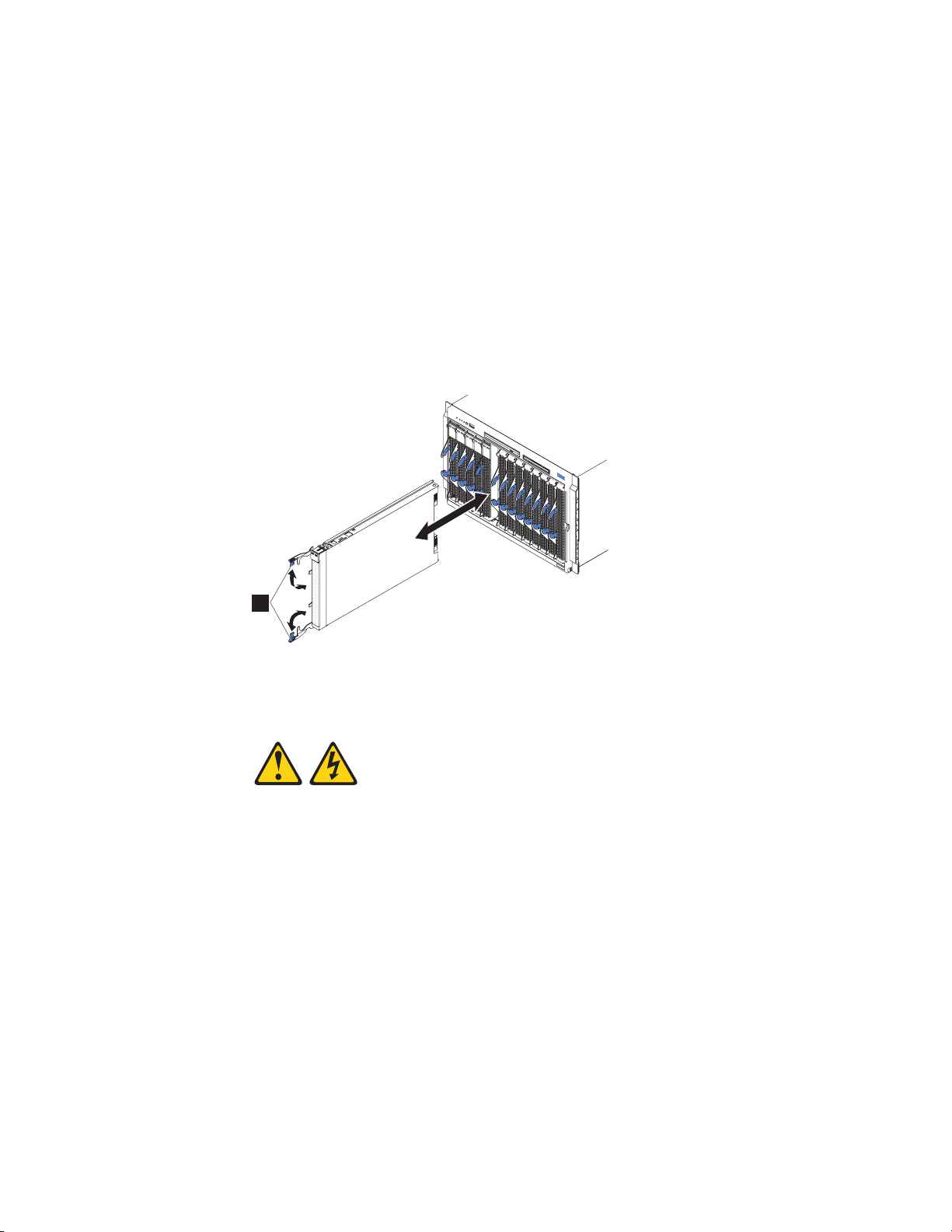
1. Read “Safety” on page v and the “Installation guidelines” on page 23.
2. Lower the cover so that the slots at the rear slide down onto the pins (1 in
Figure 22 on page 43) at the rear of the blade server. Before you close the cover,
verify that all components are installed and seated correctly and that you have
not left loose tools or parts inside the blade server.
3. Pivot the cover to the closed position until the releases (as shown by 2 in the
expansion unit and by 3 in the base unit) click into place in the cover.
4. Install the blade server into the BladeCenter unit. See “Installing the blade
server in a BladeCenter unit.”
Installing the blade server in a BladeCenter unit
Install the blade server in a BladeCenter unit to use the blade server.
1
Figure 23. Installing the blade server in a BladeCenter unit
Statement 21
CAUTION:
Hazardous energy is present when the blade server is connected to the power
source. Always replace the blade server cover before installing the blade server.
Perform the following procedure to install a blade server in a BladeCenter unit.
1. Go to http://www.ibm.com/systems/support/ to download the latest
firmware for the blade server.
Download the firmware so that you can use it later to update the blade server
after you start it.
44 JS23/JS43 Type 7778: Installation and User’s Guide
Page 57

2. Read “Safety” on page v and the “Installation guidelines” on page 23.
3. If you have not done so already, install any optional devices that you want,
such as a SAS drive or memory modules.
4. Select the bay for the blade server.
v See the online information or the Installation and User’s Guide that comes
with your BladeCenter unit to verify that the bay you choose is powered.
v Ensure proper cooling, performance, and system reliability by installing a
blade server, expansion unit, or blade filler in each blade bay.
v Reinstall a blade server in the same blade bay to preserve some
configuration information and update options that are established by blade
bay. Reinstalling into a different blade bay can have unintended
consequences, which might include reconfiguring the blade server.
5. Verify that the release handles on the blade server are in the open position
(perpendicular to the blade server, as shown in 1 in Figure 23 on page 44).
6. If you installed a filler blade or another blade server in the bay from which
you removed the blade server, remove it from the bay.
7. Slide the blade server into the blade bay from which you removed it until the
blade server stops.
The spring-loaded doors farther back in the bay that cover the bay opening
move out of the way as you insert the blade server.
8. Push the release handles on the front of the blade server to close and lock
them.
The discovery and initialization process can take up to three minutes to
complete. The discovery and initialization process is complete when the green
LED stops flashing rapidly and begins to flash slowly. At this point, you can
power on the blade server.
9. Turn on the blade server. See “Turning on the blade server” on page 16.
10. Verify that the power-on LED on the blade server control panel is lit
continuously. The continuous light indicates that the blade server is receiving
power and is turned on.
11. Optional: Write identifying information on one of the user labels that come
with the blade servers and place the label on the BladeCenter unit bezel.
Important: Do not place the label on the blade server or in any way block the
ventilation holes on the blade server. See the online information or the
documentation that comes with your BladeCenter unit for information about
label placement.
12. Use the SMS Utility program to configure the blade server. See “Using the
SMS utility” on page 50.
13. Also use the management module to configure the blade server. See the
documentation for the management module to understand the functions that
the management module provides.
Chapter 3. Installing and removing options 45
Page 58

If you have changed the configuration of the blade server or if this is a different
blade server than the one you removed, you must configure the blade server. You
might also have to install the blade server operating system.
See the ″Installing the operating system″ in the online information or the
Installation and User’s Guide PDF for detailed information about these tasks.
See Chapter 5, “Installing the operating system,” on page 55.
Input/output connectors and devices
The input/output connectors that are available to the blade server are supplied by
the BladeCenter unit.
See the documentation that comes with the BladeCenter unit for information about
the input/output connectors.
The blade server has a media-tray select button on the control panel. See “Blade
server control panel buttons and LEDs” on page 13 for information about this
button and its function.
The Ethernet controllers on the blade server communicate with the network
through the Ethernet-compatible I/O modules on the BladeCenter unit. Network
signals to and from the blade server or any expansion cards are automatically
routed to a same-network-interface I/O module through circuitry in the
BladeCenter unit.
46 JS23/JS43 Type 7778: Installation and User’s Guide
Page 59

Chapter 4. Configuring the blade server
While the firmware is running POST and before the operating system starts, a
POST menu with POST indicators is displayed. The POST indicators are the words
Memory, Keyboard, Network, SCSI, and Speaker that are displayed as each component
is tested. You can then select configuration utilities from the POST menu.
v System management services (SMS)
Use the system management services (SMS) utility to view information about
your system or partition and to perform tasks such as setting up remote IPL,
changing self configuring SCSI device (SCSD) settings, and selecting boot
options. The SMS utility can be used for AIX or Linux partitions. See “Using the
SMS utility” on page 50 for more information.
v Default boot list
Use this utility to initiate a system boot in service mode through the default
service mode boot list. This mode attempts to boot from the first device of each
type that is found in the list.
Note: This is the preferred method of starting the stand-alone AIX diagnostics
from CD.
v Stored boot list
Use this utility to initiate a system boot in service mode, using the customized
service mode boot list that was set up by AIX when AIX was first booted, or
manually using the AIX service aids.
v Open firmware prompt
This utility is for advanced users of the IEEE 1275 specifications only.
v Management module
Use the management module to change the boot list, determine which firmware
image to boot, and perform other configuration tasks.
© Copyright IBM Corp. 2009 47
Page 60

Updating the firmware
IBM periodically makes firmware updates available for you to install on the blade
server, the management module, or expansion cards in the blade server.
Important: To avoid problems and to maintain proper system performance, always
verify that the blade server BIOS, service processor, and diagnostic firmware levels
are consistent for all blade servers within the BladeCenter unit. See “Verifying the
system firmware levels” on page 49 for more information.
Plan to use a method of applying blade server firmware updates other than the
management module. The JS23 or JS43 blade server enhanced service processor has
a larger firmware image that makes it impractical to download and install over the
RS-485 bus of the management module. Therefore, a firmware update for the blade
server is not supported from the management module.
You can still use the other methods of performing firmware updates for the blade
server:
v In-band operating system capabilities, such as the update_flash command for
Linux and AIX or the ldfware command for Virtual I/O Server
v The firmware update function of AIX diagnostics
v The firmware update function of the stand-alone Diagnostics CD
Attention: Before the installation of the new firmware to the Temporary side
begins, the contents of the Temporary side are copied into the Permanent side.
After the firmware installation begins, the previous level of firmware on the
Permanent side is no longer available.
Use the following procedure to install updated firmware.
1. Start the TEMP image, as described in “Starting the TEMP image” on page 49.
2. Download the JS23 or JS43 firmware.
a. Go to the IBM Support site at http://www.ibm.com/systems/support/ to
download the updates.
b. Select your product, type, model, and operating system, and then click Go.
c. Click the Download tab, if necessary, for device driver and firmware
updates.
d. Download the firmware to the /tmp/fwupdate directory.
3. Log on to the AIX or Linux system as root, or log on to the Virtual I/O
Server/IVM alpha partition as padmin.
4. Type ls /tmp/fwupdate to identify the name of the firmware.
The result of the command lists any firmware updates that you downloaded to
the directory, such as the following update, for example:
01EA3xx_yyy_zzz
48 JS23/JS43 Type 7778: Installation and User’s Guide
Page 61

5. Install the firmware update with one of the following methods:
v Install the firmware with the in-band diagnostics of your AIX system, as
described in Using the AIX diagnostics to install the server firmware update
through AIX.
v Install the firmware with the update_flash command on AIX:
cd /tmp/fwupdate
/usr/lpp/diagnostics/bin/update_flash -f 01EA3xx_yyy_zzz
v Install the firmware with the update_flash command on Linux:
cd /tmp/fwupdate
/usr/sbin/update_flash -f 01EA3xx_yyy_zzz
v Install the firmware with the ldfware command on Virtual I/O Server:
cd /tmp/fwupdate
ldfware -file 01EA3xx_yyy_zzz
Reference codes CA2799FD and CA2799FF are displayed alternately on the
control panel during the server firmware installation process. The system
automatically powers off and on when the installation is complete.
6. Verify that the update installed correctly, as described in “Verifying the system
firmware levels.”
Starting the TEMP image
Start the TEMP image before you update the firmware.
Perform the following procedure to start the TEMP image.
1. Access the advanced management module.
See the BladeCenter Management Module Command-Line Interface Reference Guide
or the BladeCenter Serial-Over-LAN Setup Guide for more information.
2. Click Blade Tasks → Configuration → Boot Mode.
3. Click the applicable JS23 or JS43 blade server in the list of blade servers in the
BladeCenter unit.
4. Select Temporary to force the system to start from the TEMP image.
5. Restart the blade server.
6. Verify that the system starts from the TEMP image, as described in “Verifying
the system firmware levels.”
Verifying the system firmware levels
The diagnostics program displays the current system firmware levels for the TEMP
and PERM images. This function also displays which image the blade server used
to start up.
1. Start the diagnostics program.
See the online information center or the Problem Determination and Service Guide
for information about running the diagnostics program.
The online BladeCenter information center is available in the IBM BladeCenter
Information Center at http://publib.boulder.ibm.com/infocenter/bladectr/
documentation/index.jsp.
Chapter 4. Configuring the blade server 49
Page 62

2. From the Function Selection menu, select Task Selection and press Enter.
3. From the Tasks Selection List menu, select Update and Manage System Flash
and press Enter.
The Update and Manage System Flash menu is displayed. The top of the
window displays the system firmware level for the PERM and the TEMP
images and the image that the blade server used to start.
Note: If the TEMP image level is more current than the PERM image, commit
the TEMP image.
See the online information center or the Problem Determination and Service Guide
for information about committing the TEMP system firmware image.
4. When you have verified the firmware levels, press F3 until the Diagnostic
Operating Instructions window is displayed; then press F3 again to exit the
diagnostic program.
Using the SMS utility
Use the System Management Services (SMS) utility to perform a variety of
configuration tasks on the JS23 or JS43 blade server.
Starting the SMS utility
Start the SMS utility to configure the blade server.
1. Turn on or restart the blade server, and establish an SOL session with it.
See the BladeCenter Management Module Command-Line Interface Reference Guide
or the BladeCenter Serial-Over-LAN Setup Guide for more information.
2. When the POST menu and indicators are displayed, press the 1 key after the
word Keyboard is displayed and before the word Speaker is displayed .
3. Follow the instructions on the screen.
SMS utility menu choices
Select SMS tasks from the SMS utility main menu. Choices on the SMS utility main
menu depend on the version of the firmware in the blade server. Some menu
choices might differ slightly from these descriptions.
v Select Language
Select this choice to change the language that is used to display the SMS menus.
v Setup Remote IPL (Initial Program Load)
Select this choice to enable and set up the remote startup capability of the blade
server or partition.
v Change SCSD Settings
Select this choice to view and change the addresses of the self configuring SCSI
device (SCSD) controllers that are attached to the blade server.
v Select Console
Select this choice to select the console on which the SMS menus are displayed.
v Select Boot Options
Select this choice to view and set various options regarding the installation
devices and boot devices.
Note: If a device that you are trying to select (such as a USB CD drive in the
BladeCenter media tray) is not displayed in the Select Device Type menu, select
List all Devices and select the device from that menu.
50 JS23/JS43 Type 7778: Installation and User’s Guide
Page 63

Creating a CE login
If the blade server is running an AIX operating system, you can create a customer
engineer (CE) login to perform operating system commands that are required to
service the system without being logged in as a root user.
The CE login must have a role of Run Diagnostics and be a primary group of
System. This enables the CE login to perform the following tasks:
v Run the diagnostics, including the service aids, certify, and format.
v Run all the operating-system commands that are run by system group users.
v Configure and unconfigure devices that are not in use.
In addition, this login can have Shutdown Group enabled to allow use of the
Update System Microcode service aid and the shutdown and reboot operations.
The recommended CE login user name is qserv.
Configuring the Gigabit Ethernet controllers
Two Ethernet controllers are integrated on the blade server system board. You
must install a device driver to enable the blade server operating system to address
the Ethernet controllers.
Each controller provides a 1000 Mbps full-duplex interface for connecting to one of
the Ethernet-compatible I/O modules in I/O-module bays 1 and 2, which enables
simultaneous transmission and reception of data on the Ethernet local area
network (LAN).
The routing from an Ethernet controller to an I/O-module bay varies according to
the blade server type, the BladeCenter unit, and the operating system that is
installed. For example, each Ethernet controller on the JS23 or JS43 system board is
routed to a different I/O module in I/O module bay 1 or module bay 2 of the
BladeCenter H or HT.
See “Blade server Ethernet controller enumeration” on page 52 for information
about how to determine the routing from an Ethernet controller to an I/O-module
bay for the blade server.
Note: Other types of blade servers, such as the BladeCenter HS20 Type 8678 blade
server, in the same BladeCenter unit as the JS23 or JS43 blade server might have
different Ethernet controller routing. See the documentation for a blade server for
information.
You do not have to configure controllers for the blade server operating system.
However, you must install a device driver for the blade server operating system to
address the Ethernet controllers. For device drivers and information about
configuring Ethernet controllers, see the Broadcom NetXtreme Gigabit Ethernet
Software CD that comes with the blade server. For updated information about
configuring the controllers, see http://www.ibm.com/systems/support/.
The Ethernet controllers in your blade server support failover, which provides
automatic redundancy for the Ethernet controllers. Failover capabilities vary per
BladeCenter unit.
Chapter 4. Configuring the blade server 51
Page 64

Without failover, only one Ethernet controller can be connected from each server to
each virtual LAN or subnet. With failover, you can configure more than one
Ethernet controller from each server to attach to the same virtual LAN or subnet.
Either one of the integrated Ethernet controllers can be configured as the primary
Ethernet controller. If you have configured the controllers for failover and the
primary link fails, the secondary controller takes over. When the primary link is
restored, the Ethernet traffic switches back to the primary Ethernet controller. See
the operating-system device-driver documentation for information about
configuring for failover.
Important: To support failover on the blade server Ethernet controllers, the
Ethernet switch modules in the BladeCenter unit must have identical
configurations.
Blade server Ethernet controller enumeration
The enumeration of the Ethernet controllers in a blade server is operating-system
dependent. You can verify the Ethernet controller designations that a blade server
uses through the operating-system settings.
The routing of an Ethernet controller to a particular I/O-module bay depends on
the type of blade server. You can verify which Ethernet controller is routed to
which I/O-module bay by using the following test:
1. Install only one Ethernet switch module or pass-thru module in I/O-module
bay 1.
2. Make sure that the ports on the switch module or pass-thru module are
enabled. Click I/O Module Tasks → Admin/Power/Restart in the
management-module Web interface.
3. Enable only one of the Ethernet controllers on the blade server. Note the
designation that the blade server operating system has for the controller.
4. Ping an external computer on the network that is connected to the switch
module or pass-thru module. If you can ping the external computer, the
Ethernet controller that you enabled is associated with the switch module or
pass-thru module in I/O-module bay 1. The other Ethernet controller in the
blade server is associated with the switch module or pass-thru module in
I/O-module bay 2.
If you have installed an I/O expansion card in the blade server, communication
from the expansion card should be routed to I/O-module bays 3 and 4, if these
bays are supported by your BladeCenter unit. You can verify which controller on
the card is routed to which I/O-module bay by performing the same test and
using a controller on the expansion card and a compatible switch module or
pass-thru module in I/O-module bay 3 or 4.
52 JS23/JS43 Type 7778: Installation and User’s Guide
Page 65

MAC addresses for host Ethernet adapters
Two integrated Ethernet controllers in the JS23 blade server and JS43 blade server
each provide a Host Ethernet Adapter (HEA) that, in turn, provides virtual logical
host Ethernet adapters (LHEAs) to client logical partitions (LPARs). The Virtual I/O
Server software uses LHEAs as if they were real physical adapters.
The logical HEAs in the JS23 and JS43 blade servers bypass the need for further
bridging from Virtual I/O Server, because the LHEAs connect directly to the
integrated Ethernet controllers in the blade server, and from there to the I/O
modules in the BladeCenter unit.
The JS23 and JS43 blade servers use two physical HEA ports and 14 logical HEA
ports to share the two integrated physical Ethernet adapters on the blade server.
The 14 logical HEA medium access control (MAC) addresses are in the same range
as the two integrated Ethernet controllers (eth0 and eth1) and the two associated
physical HEA ports on the blade server.
The MAC addresses of the two physical HEAs are displayed in the advanced
management module. The MAC address of the first integrated Ethernet controller
(eth0) is listed on a label on the blade server. The label also lists the last MAC
address. Table 6 shows the relative addressing scheme.
Table 6. MAC addressing scheme for physical and logical host Ethernet adapters
Node
Integrated Ethernet
controller eth0
Integrated Ethernet
controller eth1
HEA port 0 MAC address 1 MAC + 2 00:1A:64:44:0e:c6
HEA port 1 MAC address 2 MAC + 3 00:1A:64:44:0e:c7
Logical HEA ports MAC +4 to MAC +16
Logical HEA port
Name in
management module
Relation to the MAC
that is listed on the
JS23 label
Same as first MAC
address
MAC + 1 00:1A:64:44:0e:c5
MAC +17
Same as last MAC
address on the label
Example
00:1A:64:44:0e:c4
00:1A:64:44:0ec8 to
00:1A:64:44:0ed5
00:1A:64:44:0ec8 to
00:1A:64:44:0ed5
For more information about planning, deploying, and managing the use of host
Ethernet adapters, see the Configuring section of the PowerVM Information
Roadmap.
Chapter 4. Configuring the blade server 53
Page 66

Updating IBM Director
If you plan to use IBM Director to manage the blade server, you must check for the
latest applicable IBM Director updates and interim fixes.
To install the IBM Director updates and any other applicable updates and interim
fixes, complete the following steps.
Note: Changes are made periodically to the IBM Web site. The actual procedure
might vary slightly from what is described in this procedure.
1. Check for the latest version of IBM Director:
a. Go to the IBM Director download site at http://www.ibm.com/systems/
management/director/downloads.html.
b. If the drop-down list shows a newer version of IBM Director than the
version that comes with the blade server, follow the instructions on the Web
page to download the latest version.
2. Install IBM Director.
3. Download and install any applicable updates or interim fixes for the blade
server:
a. Go to the IBM Support site at http://www.ibm.com/systems/support/.
b. Under Product support, click BladeCenter.
c. Under Popular links, click Software and device drivers.
d. Click BladeCenter JS23 or BladeCenter JS43 to display the list of
downloadable files for the blade server.
54 JS23/JS43 Type 7778: Installation and User’s Guide
Page 67

Chapter 5. Installing the operating system
Before you install the operating system on the blade server, verify that the blade
server is installed in the BladeCenter unit, the management-module firmware is at
the latest available level, and the blade server is turned on.
If you are not using an unattended network-installation method to install your
operating system, you must first provide a Serial over LAN (SOL) connection to
the blade server to install your operating system. If you have not already done so,
configure the SOL feature on the blade server to establish an SOL connection,
enable the SOL feature, and start an SOL session. For instructions, see the IBM
BladeCenter Serial over LAN Setup Guide and the BladeCenter Management Module
Command-Line Interface Reference Guide. For information about SOL commands, see
the documentation for your operating system.
Important:
v If you plan to install the operating system through the Ethernet network, you
must install and configure a second Ethernet switch module into the applicable
I/O-module bay of the BladeCenter unit. For additional information, see:
– “Configuring the Gigabit Ethernet controllers” on page 51
– “Blade server Ethernet controller enumeration” on page 52
– The documentation that comes with the Ethernet switch module that you are
using
v After you install the operating system on the blade server, you must install any
service packs or update packages that come with the operating system. For
additional information, see the instructions that come with your
operating-system documentation and the service packs or update packages.
v The blade server has no external USB ports, but communicates with and uses
the removable-media drives and USB ports that are in the media tray of the
BladeCenter unit.
v The operating system in the blade server must provide USB support for the
blade server to recognize and use the removable-media drives in the
BladeCenter unit. The BladeCenter unit uses USB for internal communication
with these devices.
v For the BladeCenter JS23 blade server and JS43 blade server, if you plan to
install an Ethernet expansion card, first install the operating system to enable the
onboard ports to be recognized and configured before the ports on the
expansion card. If you install the Ethernet expansion card before you install the
operating system, the expansion card ports will be assigned before the onboard
ports.
See the ServerProven Web site for information about supported operating-system
versions and all JS23 blade server and JS43 blade server optional devices.
© Copyright IBM Corp. 2009 55
Page 68

Locating the installation instructions
You can order the JS23 blade server and JS43 blade server with either Virtual I/O
Server or AIX already installed. If you did not, you can install AIX, Linux, or
Virtual I/O Server as a native operating system. After installing Virtual I/O Server,
you can install AIX, Linux, or IBM i operating system (formerly known as i5/OS)
as a client operating system in a logical partition (LPAR).
After you configure the blade server hardware, go to the operating-system
documentation for the latest operating-system installation instructions. See the
following operating system descriptions for more information:
v Installing Virtual I/O Server
See the Installing section of the PowerVM Information Roadmap.
If you did not order the JS23 blade server and JS43 blade server with the Virtual
I/O Server software installed, you can use the Virtual I/O Server DVD in the
product package to install Virtual I/O Server and set up a virtual environment
that supports client operating systems in logical partitions. You can then install
any of the supported operating systems as a client in an LPAR.
The order of installation of Virtual I/O Server and the operating systems is
important. You can update the firmware first with the stand-alone Diagnostics
CD, but you must install the Virtual I/O Server software before you install any
other software. The Virtual I/O Server software creates the Integrated Virtual
Manager administrator console and the first logical partition, which Virtual I/O
Server and Integrated Virtual Manager occupy.
After you install Virtual I/O Server, you can use Integrated Virtual Manager and
Micro-Partitioning
v Installing Linux
You can install a Linux operating system by following the installation
instructions in the IBM Systems Information Center.
The online Linux installation instructions are available in the Linux on
BladeCenter JS22 topic in the IBM Systems Information Center.
v Installing IBM i
You can install the IBM i operating system in a client partition of the Virtual I/O
Server.
See the IBM i on a POWER Blade Read-me First document on the IBM Web site.
Additional installation information and IBM i restrictions are described in i5/OS
client partition considerations.
Also see the IBM System i Information Roadmap.
v Installing AIX
You can install the AIX operating system by following the installation
instructions in the IBM Systems Information Center.
See the online AIX Installation and migration topic for more information. You
can find more information about AIX in the IBM System p Information
Roadmap on the IBM Web site.
™
to create client partitions for client operating systems.
Note: After you install AIX from CD or DVD, using the keyboard and video
interface, run the change console command and restart the blade server to
switch the AIX console to an SOL connection. (The command does not affect the
console that is used by partition firmware.) You can use the following
commands:
chcons /dev/vty0
shutdown -Fr
56 JS23/JS43 Type 7778: Installation and User’s Guide
Page 69

Notes:
1. Some optional devices have device drivers that you must install. See the
documentation that comes with the devices for information about installing any
required device drivers.
If your operating system does not have the required device drivers, contact
your IBM marketing representative or authorized reseller, or see your
operating-system documentation for additional information.
2. The IBM Remote Deployment Manager (RDM) program does not support the
BladeCenter JS23 blade server and JS43 blade server. However, you can use the
following programs for remote deployment:
v For AIX, Red Hat Linux, or SUSE Linux operating-system deployments, you
can use Cluster Systems Management (CSM) from IBM. Go to
http://www.ibm.com/servers/eserver/clusters/software/.
v For AIX operating-system deployments, you can use Network Installation
Manager (NIM) from IBM. See your AIX operating-system documentation for
additional information.
v For SUSE Linux operating-system deployments, you can use the AutoYast
utility program from Novell, Inc. Go to http://www.suse.de/~nashif/
autoinstall/.
After you install the operating system, install operating system updates; then,
install any utilities that apply to your operating system.
Installing service and productivity tools for Linux on POWER
Linux on POWER service and productivity tools include hardware diagnostic aids
and productivity tools, and installation aids. The installation aids are provided in
the IBM Installation Toolkit for Linux on POWER, a set of tools that aids the
installation of Linux on IBM servers with POWER architecture. You can also use
the tools to update the JS23 blade server and JS43 blade server firmware.
The hardware diagnostic aids and productivity tools are available as downloadable
Red Hat Package Manager (RPM) files for Red Hat Enterprise Linux (RHEL) and
SUSE Linux Enterprise Server (SLES). The IBM Installation Toolkit for Linux on
POWER is available as an ISO compact disc (CD) image, which you can use to
create your own CD. The Service and productivity tools for Linux on POWER
systems site describes how to create a CD.
The hardware diagnostic aids and productivity tools are required for such
hardware reliability, availability, and serviceability (RAS) functions as first-failure
data-capture and error-log analysis. With the tools installed, problem determination
and correction are greatly enhanced and the likelihood of an extended system
outage is reduced.
For example, the update_flash command for installing system firmware updates
can be performed only if the hardware diagnostic aids and productivity tools are
installed.
Other tools modify various serviceability policies, manipulate system LEDs, update
the bootlist, and capture extended error data to aid analysis of intermittent errors.
Other commands and a boot-time scanning script constitute a hardware inventory
system. The lsvpd command provides vital product data (VPD) about hardware
components.
Chapter 5. Installing the operating system 57
Page 70

The Error Log Analysis (ELA) tool provides automatic analysis and notification of
errors that are reported by the platform firmware. ELA writes analyzed error data
to /var/log/platform and to the servicelog. If a corrective action is required, a
notification event sends the event to registered tools and subscribed users.
Install the LINUX operating system before you download and install the hardware
diagnostic aids and productivity tools for Linux on POWER. The Installation
Toolkit for Linux on Power is provided as-is only. You are not entitled to IBM
Software Support for the Installation Toolkit.
Install the Virtual I/O Server and the Integrated Virtualization Manager (IVM)
before you install your Linux operating system if you plan to have a virtual
environment.
58 JS23/JS43 Type 7778: Installation and User’s Guide
Page 71

Chapter 6. Solving problems
Use the diagnostic tools that are available to help you solve some common
problems that might occur while you are setting up the blade server.
If you install the blade server in the BladeCenter unit and the blade server does
not start, perform the following actions:
v Make sure that the BladeCenter unit is correctly connected to a power source.
v Reseat the blade server in the BladeCenter unit, as described in “Installing the
blade server in a BladeCenter unit” on page 44.
v If the power-on LED is flashing slowly, turn on the blade server, as described in
“Turning on the blade server” on page 16.
v If you have just added a new optional device or component, make sure that it is
correctly installed and compatible with the blade server and its components. If
the device or component is not compatible, remove it from the blade server,
reinstall the blade server in the BladeCenter unit, and then restart the blade
server.
If the blade server does not start after you have performed the preceding actions,
see the online information or the Problem Determination and Service Guide on the
IBM BladeCenter Documentation CD.
If you cannot see the AIX console after you install AIX locally by using the
keyboard/video select button and local media, run the change console command
and restart the blade server to switch the AIX console to a SOL connection:
chcons /dev/vty0
shutdown -Fr
The commands do not affect the console that is used by partition firmware.
The following tools are available to help you diagnose and solve hardware-related
problems:
v Power-on self-test (POST) firmware checkpoints and error codes
The firmware checkpoints are progress codes that your blade server writes to the
management-module event log during POST.
See the online information or the Problem Determination and Service Guide for
more information.
v Firmware error codes and location codes
For detailed descriptions of the firmware error codes, see the online information
or the Problem Determination and Service Guide.
Some firmware error codes also include location codes. The location code
information is required to identify the failing component. Check the event log in
the management module to determine the location code information that
corresponds to the firmware error code.
For additional information about location codes, see the online information or
the Problem Determination and Service Guide.
v Troubleshooting tables
Use the troubleshooting tables to find solutions to problems that have
identifiable symptoms.
© Copyright IBM Corp. 2009 59
Page 72

See the online information or the Problem Determination and Service Guide for
your blade server.
v Diagnostic utilities for the Linux operating system
Diagnostic utilities for the Linux operating system are available from IBM. To
obtain these utilities and information about them, complete the following steps:
1. Go to http://www.ibm.com/systems/bladecenter/.
2. Under Product support, click BladeCenter.
3. From the Product family menu, select BladeCenter JS23 or BladeCenter 43.
4. From the Operating system menu, select your Linux operating system, and
then click Go to display the available downloads.
v Diagnostic utilities for the AIX operating system
An AIX operating-system diagnostic CD, also known as the stand-alone
Diagnostics CD, is available from IBM. You can start the CD from a CD drive or
from NIM. To download the CD image, go to http://www14.software.ibm.com/
webapp/set2/sas/f/diags/home.html.
See the Problem Determination and Service Guide for instructions for using the
diagnostic utilities.
v Diagnostic utilities for other operating systems
Other supported operating systems might have diagnostic tools that are
available through the operating system. See your operating-system
documentation for more information.
v Light path diagnostics
Use light path diagnostics LEDs on the system board to identify system errors. If
the system-error LED on the system LED panel on the front or rear of the
BladeCenter unit is lit, one or more error LEDs on the BladeCenter unit
components also might be lit. These LEDs help identify the cause of the
problem.
Notes:
v View the system event log in the BladeCenter management module.
v Before you have the blade server serviced, verify that you provide a Serial over
LAN (SOL) connection to the blade server. To do this, you must configure the
SOL feature on the blade server and start an SOL session as described in the
IBM BladeCenter Serial over LAN Setup Guide.
v You can also configure the service processor IP address by using the
management module, and set up a SOL connection to the service processor.
60 JS23/JS43 Type 7778: Installation and User’s Guide
Page 73

Appendix A. Getting help and technical assistance
If you need help, service, or technical assistance or just want more information
about IBM products, you will find a wide variety of sources available from IBM to
assist you.
This section contains information about where to go for additional information
about IBM and IBM products, what to do if you experience a problem with your
system, and whom to call for service, if it is necessary.
Before you call
Before you call, make sure that you have taken these steps to try to solve the
problem yourself.
v Check all cables to make sure that they are connected.
v Check the power switches to make sure that the system and any optional
devices are turned on.
v Use the troubleshooting information in your system documentation, and use the
diagnostic tools that come with your system.
Information about diagnostic tools is in the online information and in the
Problem Determination and Service Guide on the IBM Documentation CD that comes
with your system.
v Go to the IBM support Web site at http://www.ibm.com/systems/support/ to
check for technical information, hints, tips, and new device drivers or to submit
a request for information.
You can solve many problems without outside assistance by following the
troubleshooting procedures that IBM provides in the online help or in the
documentation that is provided with your IBM product. The documentation that
comes with IBM systems also describes the diagnostic tests that you can perform.
Most systems, operating systems, and programs come with documentation that
contains troubleshooting procedures and explanations of error messages and error
codes. If you suspect a software problem, see the documentation for the operating
system or program.
Using the documentation
Information about your IBM system and preinstalled software, if any, or optional
device is available in the documentation that comes with the product. That
documentation can include printed documents, online documents, readme files,
and help files.
© Copyright IBM Corp. 2009 61
Page 74

See the troubleshooting information in your system documentation for instructions
for using the diagnostic programs. The troubleshooting information or the
diagnostic programs might tell you that you need additional or updated device
drivers or other software. IBM maintains pages on the World Wide Web where you
can get the latest technical information and download device drivers and updates.
To access these pages, go to http://www.ibm.com/systems/support/ and follow
the instructions. Also, some documents are available through the IBM Publications
Center at http://www.ibm.com/shop/publications/order/.
Getting help and information from the World Wide Web
On the World Wide Web, the IBM Web site has up-to-date information about IBM
systems, optional devices, services, and support.
The IBM Web site has up-to-date information about IBM BladeCenter systems,
optional devices, services, and support at www.ibm.com/systems/support/.
®
The address for IBM System x
systems/x/. The address for IBM BladeCenter information is http://
www.ibm.com/systems/bladecenter/. The address for IBM IntelliStation
information is http://www.ibm.com/intellistation/.
You can find service information for IBM systems and optional devices at
http://www.ibm.com/systems/support/.
and xSeries®information is http://www.ibm.com/
®
Calling IBM for service
Call IBM for service after you collect as much as possible of the following
information.
Before calling for service, collect as much as possible of the following available
information:
v Machine type and model
v Hard disk drive upgrades
v Failure symptoms:
– Does the blade server fail the diagnostic programs? If so, what are the error
codes?
– What occurs? When? Where?
– Is the failure repeatable?
– Has the current server configuration ever worked?
– What changes, if any, were made before it failed?
– Is this the original reported failure, or has this failure been reported before?
v Diagnostic program type and version level
v Hardware configuration (print screen of the system summary)
v Firmware level
v Operating-system type and version level
You can solve some problems by comparing the configuration and software setups
between working and nonworking blade server. When you compare blade servers
to each other for diagnostic purposes, consider them identical only if all the
following factors are exactly the same in all of the blade servers:
v Machine type and model
v Firmware level
62 JS23/JS43 Type 7778: Installation and User’s Guide
Page 75

v Adapters and attachments, in the same locations
v Address cabling
v Software versions and levels
v Diagnostic program type and version level
v Configuration option settings
v Operating-system control-file setup
See Appendix A, “Getting help and technical assistance,” on page 61 for
information about how to call IBM for service.
Software service and support
Through IBM Support Line, you can get telephone assistance, for a fee, with usage,
configuration, and software problems with System x and xSeries servers,
BladeCenter products, IntelliStation workstations, and appliances.
For information about which products are supported by Support Line in your
country or region, see www.ibm.com/services/sl/products/.
For more information about Support Line and other IBM services, see
www.ibm.com/services/, or see www.ibm.com/planetwide/ for support telephone
numbers. In the U.S. and Canada, call 1-800-IBM-SERV (1-800-426-7378).
Hardware service and support
You can receive hardware service through your IBM reseller or IBM Services.
To locate a reseller authorized by IBM to provide warranty service, go to
http://www.ibm.com/partnerworld/ and click Find a Business Partner on the
right side of the page. For IBM support telephone numbers, see
http://www.ibm.com/planetwide/. In the U.S. and Canada, call 1-800-IBM-SERV
(1-800-426-7378).
In the U.S. and Canada, hardware service and support is available 24 hours a day,
7 days a week. In the U.K., these services are available Monday through Friday,
from 9 a.m. to 6 p.m.
IBM Taiwan product service
You can contact local IBM product service in Taiwan.
Appendix A. Getting help and technical assistance 63
Page 76

IBM Taiwan product service contact information:
IBM Taiwan Corporation
3F, No 7, Song Ren Rd.
Taipei, Taiwan
Telephone: 0800-016-888
64 JS23/JS43 Type 7778: Installation and User’s Guide
Page 77

Appendix B. Notices
This information was developed for products and services offered in the U.S.A.
IBM may not offer the products, services, or features discussed in this document in
other countries. Consult your local IBM representative for information on the
products and services currently available in your area. Any reference to an IBM
product, program, or service is not intended to state or imply that only that IBM
product, program, or service may be used. Any functionally equivalent product,
program, or service that does not infringe any IBM intellectual property right may
be used instead. However, it is the user’s responsibility to evaluate and verify the
operation of any non-IBM product, program, or service.
IBM may have patents or pending patent applications covering subject matter
described in this document. The furnishing of this document does not give you
any license to these patents. You can send license inquiries, in writing, to:
IBM Director of Licensing
IBM Corporation
North Castle Drive
Armonk, NY 10504-1785
U.S.A.
INTERNATIONAL BUSINESS MACHINES CORPORATION PROVIDES THIS
PUBLICATION “AS IS” WITHOUT WARRANTY OF ANY KIND, EITHER
EXPRESS OR IMPLIED, INCLUDING, BUT NOT LIMITED TO, THE IMPLIED
WARRANTIES OF NON-INFRINGEMENT, MERCHANTABILITY OR FITNESS
FOR A PARTICULAR PURPOSE. Some states do not allow disclaimer of express or
implied warranties in certain transactions, therefore, this statement may not apply
to you.
This information could include technical inaccuracies or typographical errors.
Changes are periodically made to the information herein; these changes will be
incorporated in new editions of the publication. IBM may make improvements
and/or changes in the product(s) and/or the program(s) described in this
publication at any time without notice.
Any references in this information to non-IBM Web sites are provided for
convenience only and do not in any manner serve as an endorsement of those Web
sites. The materials at those Web sites are not part of the materials for this IBM
product, and use of those Web sites is at your own risk.
IBM may use or distribute any of the information you supply in any way it
believes appropriate without incurring any obligation to you.
© Copyright IBM Corp. 2009 65
Page 78

Trademarks
IBM, the IBM logo, and ibm.com®are trademarks or registered trademarks of
International Business Machines Corporation in the United States, other countries,
or both.
If these and other IBM trademarked terms are marked on their first occurrence in
this information with a trademark symbol (
®or™
), these symbols indicate U.S.
registered or common law trademarks owned by IBM at the time this information
was published. Such trademarks may also be registered or common law
trademarks in other countries. A current list of IBM trademarks is available on the
Web at “Copyright and trademark information” athttp://www.ibm.com/legal/
copytrade.shtml.
®
Adobe and PostScript
are either registered trademarks or trademarks of Adobe
Systems Incorporated in the United States and/or other countries.
Cell Broadband Engine is a trademark of Sony Computer Entertainment, Inc., in
the United States, other countries, or both and is used under license therefrom.
®
, Intel®Xeon®, Itanium®, and Pentium®are trademarks or registered
Intel
trademarks of Intel Corporation or its subsidiaries in the United States and other
countries.
™
and all Java-based trademarks are trademarks of Sun Microsystems, Inc., in
Java
the United States, other countries, or both.
Linux is a trademark of Linus Torvalds in the United States, other countries, or
both.
Microsoft, Windows, and Windows NT are trademarks of Microsoft Corporation in
the United States, other countries, or both.
Important notes
®
UNIX
is a registered trademark of The Open Group in the United States and
other countries.
Other company, product, or service names may be trademarks or service marks of
others.
View important assumptions about terminology and claims.
66 JS23/JS43 Type 7778: Installation and User’s Guide
Page 79

Processor speed indicates the internal clock speed of the microprocessor; other
factors also affect application performance.
CD or DVD drive speed is the variable read rate. Actual speeds vary and are often
less than the possible maximum.
When referring to processor storage, real and virtual storage, or channel volume,
KB stands for 1024 bytes, MB stands for 1 048 576 bytes, and GB stands for
1 073 741 824 bytes.
When referring to hard disk drive capacity or communications volume, MB stands
for 1 000 000 bytes, and GB stands for 1 000 000 000 bytes. Total user-accessible
capacity can vary depending on operating environments.
Maximum internal hard disk drive capacities assume the replacement of any
standard hard disk drives and population of all hard disk drive bays with the
largest currently supported drives that are available from IBM.
Maximum memory might require replacement of the standard memory with an
optional memory module.
IBM makes no representation or warranties regarding non-IBM products and
services that are ServerProven, including but not limited to the implied warranties
of merchantability and fitness for a particular purpose. These products are offered
and warranted solely by third parties.
IBM makes no representations or warranties with respect to non-IBM products.
Support (if any) for the non-IBM products is provided by the third party, not IBM.
Some software might differ from its retail version (if available) and might not
include user manuals or all program functionality.
Product recycling and disposal
See the Environmental Notices and User Guide on the Documentation CD for
information about product recycling.
Battery return program
See the Environmental Notices and User Guide on the Documentation CD for
information about the battery return program.
Appendix B. Notices 67
Page 80

Electronic emission notices
This section of the documentation includes electronic emission notices for various
countries.
Federal Communications Commission (FCC) statement
The JS23 or JS43 blade server complies to FCC rules.
Note: This equipment has been tested and found to comply with the limits for a
Class A digital device, pursuant to Part 15 of the FCC Rules. These limits are
designed to provide reasonable protection against harmful interference when the
equipment is operated in a commercial environment. This equipment generates,
uses, and can radiate radio frequency energy and, if not installed and used in
accordance with the instruction manual, may cause harmful interference to radio
communications. Operation of this equipment in a residential area is likely to cause
harmful interference, in which case the user will be required to correct the
interference at his own expense.
Properly shielded and grounded cables and connectors must be used in order to
meet FCC emission limits. IBM is not responsible for any radio or television
interference caused by using other than recommended cables and connectors or by
unauthorized changes or modifications to this equipment. Unauthorized changes
or modifications could void the user’s authority to operate the equipment.
This device complies with Part 15 of the FCC Rules. Operation is subject to the
following two conditions: (1) this device may not cause harmful interference, and
(2) this device must accept any interference received, including interference that
may cause undesired operation.
Industry Canada Class A emission compliance statement
This Class A digital apparatus complies with Canadian ICES-003.
Avis de conformité à la réglementation d’Industrie Canada
Cet appareil numérique de la classe A est conforme à la norme NMB-003 du
Canada.
Australia and New Zealand Class A statement
Attention: This is a Class A product. In a domestic environment this product may
cause radio interference in which case the user may be required to take adequate
measures.
68 JS23/JS43 Type 7778: Installation and User’s Guide
Page 81
United Kingdom telecommunications safety requirement
Notice to Customers: This apparatus is approved under approval number
NS/G/1234/J/100003 for indirect connection to public telecommunication systems
in the United Kingdom.
European Union EMC Directive conformance statement
This product is in conformity with the protection requirements of EU Council
Directive 2004/108/EC on the approximation of the laws of the Member States
relating to electromagnetic compatibility. IBM cannot accept responsibility for any
failure to satisfy the protection requirements resulting from a nonrecommended
modification of the product, including the fitting of non-IBM option cards.
This product has been tested and found to comply with the limits for Class A
Information Technology Equipment according to CISPR 22/European Standard EN
55022. The limits for Class A equipment were derived for commercial and
industrial environments to provide reasonable protection against interference with
licensed communication equipment.
Attention: This is a Class A product. In a domestic environment this product
may cause radio interference in which case the user may be required to take
adequate measures.
European Community contact:
v IBM Technical Regulations
v Pascalstr. 100, Stuttgart, Germany 70569
v Telephone: 0049 (0)711 785 1176
v Fax: 0049 (0)711 785 1283
v E-mail: tjahn@de.ibm.com
Taiwanese Class A warning statement
This is the Taiwanese Class A warning statement.
Appendix B. Notices 69
Page 82

Chinese Class A warning statement
View the Chinese Class A warning statement.
Japanese Voluntary Control Council for Interference (VCCI) statement
View the Japanese VCCI statement.
70 JS23/JS43 Type 7778: Installation and User’s Guide
Page 83

Index
Numerics
1Xe connector expansion card
removing 37
A
AIX operating system
diagnostic CD 59
diagnostic utilities Web site 59
IBM program for remote
deployment 56
Web site for remote deployment 56
assistance, getting 61
attention notices 5
Australia and New Zealand Class A
statement 68
B
baseboard management controller (BMC)
features 8
battery
connector 17
battery return program
Environmental Notices and User
Guide on the Documentation
CD 67
blade filler 25, 44
blade server
features 6, 8, 9
installing 44
removing 25
specifications 6
blade server cover
closing 43
installing 43
opening 26
removing 26
BladeCenter unit
failover support through Ethernet
switch modules 51, 52
label placement 1
power requirements 44
safety 43
system cooling requirement 24, 25,
44
buttons
CD/diskette/USB 14
control panel 13
keyboard/video 14
power-control 15
C
caution statements 5
CD, diagnostic, for AIX operating
system 59
CE login, creating 51
Chinese Class A warning statement 70
CIOv expansion card
illustration 39
installing 39
CIOv form-factor expansion card
installing 39
removing 37
Class A electronic emission notice 68
colors on components, meanings of 23
combination-form-factor expansion card
installing 41
removing 40
completing the installation 42
components
system board 17
configuration
default boot list 47
Ethernet ports 37, 55
open firmware prompt 47
stored boot list 47
system management services
(SMS) 47
configuring the blade server 47
connectors
battery 17
I/O expansion card 17
input/output 46
memory 17
microprocessor 17
serial attached SCSI (SAS) 17
system board 17
control panel, buttons and LEDs 13
controller
enumeration 52
Ethernet 51
memory 9
cover
closing 43
installing 43
opening 26
removing 26
creating
CE login 51
D
danger statements 5
data integrity 9
daughter card (see expansion card) 37
diagnostic CD for AIX operating
system 59
diagnostic tools 59
diagnostic utilities
AIX operating system 59
Linux operating system 59
other operating systems 59
DIMM
removing 33
DIMM (dual inline memory module) 34
DIMM, registered
planning 36
disk drive
installing 32
removing 31
disk drive. 8
documentation
online 2
PDFs 2
related 2
documentation browser 4
documentation CD 4
documentation, using 61
downloading installation instructions for
operating systems 56
drive
connectors 17
option, disk 32
option, SAS 8
removing 31
specifications 7
drive, disk
internal, installing 32
removing 31
E
electrical specifications 7
electronic emission Class A notice 68
electronic emission notices 68
Environmental Notices and User Guide
on the Documentation CD 67
environmental specifications 7
error log 10, 59
entries 15
Ethernet
integrated network support 8
network requirements 55
Ethernet controller
configuring 37, 51, 55
enumeration 52
failover 51
redundant network connection 51
specifications 7
EU EMC directive 69
event log 8, 60
expansion unit
installing 29
removing 27
F
failover support through Ethernet switch
modules 51, 52
fault tolerance 9
FCC Class A notice 68
features
blade server 6, 8
reliability, availability, and
serviceability (RAS) 9
service processor 7
Fibre Channel card, I/O expansion 37
© Copyright IBM Corp. 2009
71
Page 84

filler, blade 25, 44
firmware
error codes 59
Linux service aids for hardware
diagnostics 57
updates 1, 23, 48
G
getting help 61
Gigabit Ethernet card, I/O expansion 37
H
hard disk drive
connectors 17
specifications 7
support 8
hardware
service and support 63
hardware and software requirements 4
hardware problems 59
hardware service and support 63
help, getting 61
host Ethernet adapters (HEAs) 53
I
I/O expansion card 37
connectors 17
Ethernet 37, 55
installing 37
Myrinet 37
types supported 37
IBM Director
introduction 8
overview 11
updating 54
Web sites 11, 54
IBM ServerProven Web site 23
IBM Support Line 63
IBM Taiwan product service 63
image
TEMP 49
important notices 5
Industry Canada Class A emission
compliance statement 68
installation guidelines 23
installation order
memory modules 34
installing
1Xe connector for expansion card 39
blade server 44
blade server cover 43
CIOv form-factor expansion card 39
combination-form-factor expansion
card 41
expansion unit 29
hard disk drive 32
I/O expansion card 37
Linux service aids 57
memory module 34
operating system 55
options 23
solid state drive 32
update packages 55
integrated functions 7
J
Japanese VCCI statement 70
L
label placement
BladeCenter unit 44
requirements 1
LEDs
activity 15
blade-error 15
control panel 13
information 15
location 16
NMI reset 15
power-on 15
sleep 15
system board 20
Light path diagnostics 59
light path diagnostics panel 20
Linux operating system 56
diagnostic utilities Web site 59
installing service aids 57
update_flash command 57
Web site for IBM program for remote
deployment 56
Web site for other programs for
remote deployment 56
location code 59
logical HEA MAC addresses 53
M
MAC addressing scheme 53
meanings of colors
on components 23
memory module
installation order 34
installing 34
removing 33
specifications 6, 9
supported 7
memory RDIMM
planning 36
memory specifications 6
microprocessor specifications 6
Myrinet card, I/O expansion 37
N
network operating system (NOS)
installation 56
network requirements 37, 55
notes 5
notes, important 66
notices 65
electronic emission 68
FCC, Class A 68
product recycling
Environmental Notices and User
Guide on the Documentation
CD 67
notices and statements 5
O
online documentation 1, 2, 23
opening
blade server cover 26
operating systems
AIX
diagnostic CD 59
Web site for diagnostic utilities 59
Ethernet network requirements 55
installing 55, 56
Linux 56
Web site for diagnostic utilities 59
remote deployment 56
Serial Over LAN (SOL)
requirements 55
service packs 55
supported 55
update packages 55
option
handling 23, 24
installing 23
order of installation
memory modules 34
P
placement of labels 1
planning
memory RDIMM 36
port, input/output 46
power
throttling 9
power-on self-test (POST)
error logs 59
Predictive Failure Analysis (PFA) 7
problems, solving 59
product recycling 67
Environmental Notices and User
Guide on the Documentation
CD 67
publications
online 1, 23
related 2
R
RDIMM
planning 36
recycling, product
Environmental Notices and User
Guide on the Documentation
CD 67
related documentation 2
reliability, availability, and serviceability
(RAS) features 9, 57
remote deployment 56
removing
1Xe connector expansion card 37
blade server 25
blade server cover 26
CIOv form-factor expansion card 37
combination-form-factor expansion
card 40
72 JS23/JS43 Type 7778: Installation and User’s Guide
Page 85

removing (continued)
drive 31
expansion unit 27
I/O expansion card 37
memory module 33
requirements
hardware and software 4
label placement 1
operating system 55
trademarks 66
troubleshooting
diagnostic utilities programs for Linux
operating system 59
Light path diagnostics 59
Problem isolation tables 59
Web site and diagnostic CD for AIX
operating system 59
turning off the blade server 16
turning on the blade server 16
S
safety v
safety statements vi
SCSI (small computer system
interface) 32
serial attached SCSI (SAS)
drive connectors 17
Serial Attached SCSI (SAS)
drive
specifications 7
support 8
ServerProven Web site, IBM 23
service aids, Linux, installing 57
service and support, hardware 63
service packs, installing 55
service processor
specifications 7
service, calling for 62
shared Ethernet adapter 53
software service and support 63
solid state drive
installing 32
removing 31
specifications 7
solving a problem yourself 61
specifications 6
starting
TEMP image 49
starting the blade server 16
statements and notices 5
static electricity 24
static-sensitive devices, handling 24
stopping the blade server 16
supported operating systems 55
system board
connectors 17
LEDs 20
system board layouts 17
system firmware
verifying levels 49
system management services (SMS)
about 47
menu choices 50
starting 50
system management services (SMS)
utility 50
system reliability 24
system-board connectors 17
systems management 11
U
UK telecommunication safety 69
United States electronic emission Class A
notice 68
United States FCC Class A notice 68
update packages, installing 55
update_flash command 57
updating
firmware 1, 23, 48
IBM Director 54
Using the documentation 61
utility
default boot list 47
diagnostic
AIX operating system 59
Linux operating system 59
other operating systems 59
open firmware prompt 47
stored boot list 47
system management services
(SMS) 47
V
verifying system firmware levels 49
W
web site
publication ordering 62
Web site
AIX diagnostic utilities 59
IBM Director 11, 54
IBM program for remote deployment
for AIX and Linux operating
systems 56
IBM ServerProven list 23
Linux diagnostic utilities 59
Linux service aids 57
other programs for remote
deployment for Linux operating
system 56
support line, telephone numbers 63
supported blade server options 23
World Wide Web support 62
T
telephone numbers 63
TEMP image
starting 49
Index
73
Page 86

74 JS23/JS43 Type 7778: Installation and User’s Guide
Page 87

Page 88

Part Number: 44R5338
Printed in USA
(1P) P/N: 44R5338
 Loading...