

Page 1

AS/400e
AS/400e 940x RISC-to-RISC Road Map
Ve r s i o n 4
SA41-5155-04
Page 2

Page 3

AS/400e
AS/400e 940x RISC-to-RISC Road Map
Ve r s i o n 4
SA41-5155-04
Page 4

Note
Before using this information and the product it supports, be sure to read the information in Appendix H, “Notices” on
page 65.
Fifth Edition (May 2000)
This edition replaces SA41-5155-03. This edition applies only to reduced instruction set computer (RISC) systems.
© Copyright International Business Machines Corporation 1997, 2000. All rights reserved.
US Government Users Restricted Rights – Use, duplication or disclosure restricted by GSA ADP Schedule Contract
with IBM Corp.
Page 5

Contents
AS/400e 940x RISC-to-RISC Road Map,
SA41–5155–04 ............v
Who Should Read This Book .........v
Conventions and Terminology Used in This Book . . v
AS/400 Operations Navigator ........vii
Installing Operations Navigator ......viii
Information Available on the World Wide Web . . viii
Prerequisite and Related Information ......ix
How to send your comments ........xi
Chapter 1. Overview of RISC-to-RISC
Upgrades and Data Migrations .....1
What Is In this Road Map ..........1
Why Upgrade from One AS/400 System to Another? 2
What is An Upgrade? ...........2
Hardware Investment for Upgrading ......2
How Long Will the Upgrade Take? .......3
WhatisADataMigration? .........3
How Long Will the Data Migration Take?.....4
Books to Use for Software Release Upgrades . . . 5
Chapter 2. Planning Your Order for
Upgrading or Data Migration ......7
Determining Your Upgrade Needs .......7
Performance Tools for Capacity Planning and
Performance Analysis ..........7
How to Gather Configuration Information . . . 8
How to Gather Performance Information ....8
Prerequisites Before Placing an Order ......9
Version 4 Software Items .........9
Other Software Related Items ........9
HardwareConsiderations.........10
System Configuration Considerations.....10
Services and Other Assistance .......11
Model-specific Considerations for Placing an Order 11
Upgrading from a 4xx, 5xx, Sxx, or 6xx to a 7xx 13
DedicatedServerforDomino........14
Migratingfroma5xxtoan8xx........14
Upgrading from a 6xx or 7xx to an 8xx .....15
Placing the Upgrade Order .........15
Who is Responsible for Ordering the Upgrade? 15
HowtoGetHelpwiththeOrder......16
SendingtheOrdertoIBM........16
Sending the Order to a Software Service Provider
Other Than IBM ............17
Chapter 3. Procedure for an Upgrade
(RISC-to-RISC) ...........19
Who is Responsible for Upgrading the System. . . 19
What to Do When the Hardware Arrives ....20
Preparing the Current System ........21
Installing the Hardware for the RISC-to-RISC
Upgrade ...............32
Chapter 4. AS/400 940x RISC-to-RISC
Road Map - Data Migration ......33
Prerequisite for Data Migration (RISC-to-RISC) . . 33
Before the server arrives, the customer should do
thefollowing:.............33
When the new server arrives, do the following: 34
Before the data migration is to take place, do the
following on the source system: ......34
Before the data migration is to take place, do the
following on the new server: .......35
RISC-to-RISCDataMigration.......36
Appendix A. AS/400 Global Services . . 39
AS/400 Data Migration Services .......39
LPAR Planning and Implementation Services . . . 39
AS/400 V4R5 Planning and Migration Services . . 39
AS/400 System Migration Services ......39
Related Support Services ..........40
AS/400 Solution Services ..........40
Installation Services ..........40
Performance Examinations ........41
Consulting Services...........41
Midrange Enhanced Software Service (MRESS) 41
Appendix B. Enhanced Upgrade Order
Process (EUOP) ...........43
How to Use the Enhanced Upgrade Order Process 44
Appendix C. Possible AS/400
RISC-to-RISC Upgrades .......45
DedicatedServerforDomino........45
Upgrading Your Existing Model (MES) .....45
Upgrading to a New 7xx or 8xx Model .....46
Appendix D. Migrating Systems with
the System Support Program (SSP)
Operating Systems .........47
MigratingfromaModel236.........47
MigratingfromaModel436.........48
Appendix E. Considerations and
Solutions..............51
IBM HTTP Server for AS/400 ........51
Operations Console............52
OptiConnect ..............52
Integrated Netfinity Server .........52
Clustering and Logical Partitions .......52
Lotus Notes Enhanced Integration .......52
OnDemand ..............52
SRC A900 2000 Recovery ..........52
How to Move Files That Have Been Saved with
Storage Free Specified ...........53
© Copyright IBM Corp. 1997, 2000 iii
Page 6

How to Move Freed Database Files without New
Members..............53
Appendix H. Notices .........65
Trademarks..............66
Appendix F. How to Verify and Set Up
Electronic Customer Support .....55
Verifying Configuration ..........55
Setting Up ...............56
Appendix G. Obtain the Latest
Preventive Service Planning
Information .............63
Index ...............69
iv
AS400e 940x RISC-to-RISC Road Map V4R5
Page 7

AS/400e 940x RISC-to-RISC Road Map, SA41–5155–04
Use this book as a guide for planning and conducting an upgrade or data
migration, from one AS/400 reduced instruction set computer (RISC), to another
RISC model.
You can also use the RISC-to-RISC Road Map Web site as a guide for planning and
conducting an upgrade or data migration, from one reduced instruction set
computer (RISC), to another RISC model:
http://www.as400.ibm.com/tstudio/tech_ref/rrmap/
See “Prerequisite and Related Information” on page ix for a list of other required
and recommended publications.
Who Should Read This Book
This road map is for anyone who is considering an AS/400 upgrade or is involved
in migrating data from one AS/400 RISC model to another RISC model. This
audience includes:
v Customers
v Hardware services personnel
v Software services personnel
v Business partners
v Marketing representatives
Everyone involved in the model upgrade or data migration needs to know all of
the information in this book.
Each customer should have a Customer Account Team Leader, this team leader
can be a Hardware Service Representative, Software Service Representative,
Business Partner, or Marketing Representative. The Availability Center usually
assigns a Customer Account Team Leader.
Conventions and Terminology Used in This Book
This road map identifies activities, programs, tools, and references that you can use
to upgrade the model.
As you read this book, you should be aware of the following terms:
v The terms source system and target system are used throughout this manual.
The source system is the system you are upgrading from. The target system is
the system you are upgrading to.
v The term Marketing Representative can mean either an IBM Marketing
Representative,aBusiness Partner,oraServices Specialist.
v The term 1xx includes Model 150 or 170.
v The term 2xx includes Model 250 or 270.
v The term 4xx includes Model 400, 40S, or 436.
v The term 5xx includes Model 50x, 50S, 510, or 530.
v The term Sxx includes Model S10, S20, S30, S40, SB1, SB2, or SB3.
© Copyright IBM Corp. 1997, 2000 v
Page 8

v The term 6xx includes Model 600, 620, 640, or 650.
v The term 7xx includes Model 720, 730, or 740.
v The term 8xx includes Model 820, 830, or 840.
v The term AS/400e as used in this document refers to the new generation of
AS/400 systems and servers positioned for e-business: e-systems and e-servers,
for example Model 170.
v The term AS/400 as used in this document refers to:
– AS/400 system- Models 40x, 5x0, 150 and 6x0.
– AS/400 server- Models 40S, 5xS, Sxx, 170, 2xx, 7xx and 8xx..
v The term System Products Division (SPD) book-type adapter cards includes all
adapter cards that are not Peripheral Component Interconnect (PCI) adapter
cards.
In this publication, the version, release, and modification levels are shown in a
shortened form:
V3R7M0 Version 3 Release 7 Modification 0
V4R1M0 Version 4 Release 1 Modification 0
V4R2M0 Version 4 Release 2 Modification 0
V4R3M0 Version 4 Release 3 Modification 0
V4R4M0 Version 4 Release 4 Modification 0
V4R5M0 Version 4 Release 5 Modification 0
V3R7 Version 3 Release 7 Modification (any)
V4R1 Version 4 Release 1 Modification (any)
V4R2 Version 4 Release 2 Modification (any)
V4R3 Version 4 Release 3 Modification (any)
V4R4 Version 4 Release 4 Modification (any)
V4R5 Version 4 Release 5 Modification (any)
Version 4 Any version 4 release, such as, V4R1M0, V4R2M0 or V4R3M0.
Version 3 Any version 3 release, such as, V3R7M0.
Attention:
Is used in this book to indicate that a step, or process may cause loss of data.
Namely: Installing incorrect versions of the operating system.
CAUTION:
Is used in this book to indicate possible damage to the system.
Namely: Static damage to component.
vi AS400e 940x RISC-to-RISC Road Map V4R5
Page 9
DANGER
Is used in this book to indicate possible damage to the users and equipment.
Namely: Electrical shock.
In any position that contains numerals, an x = any supported value, for example
SFxxxxx,orVxRxMx.
Examples of displays might contain only pertinent information to a topic. So, some
display examples do not show all text and lines, especially blank lines.
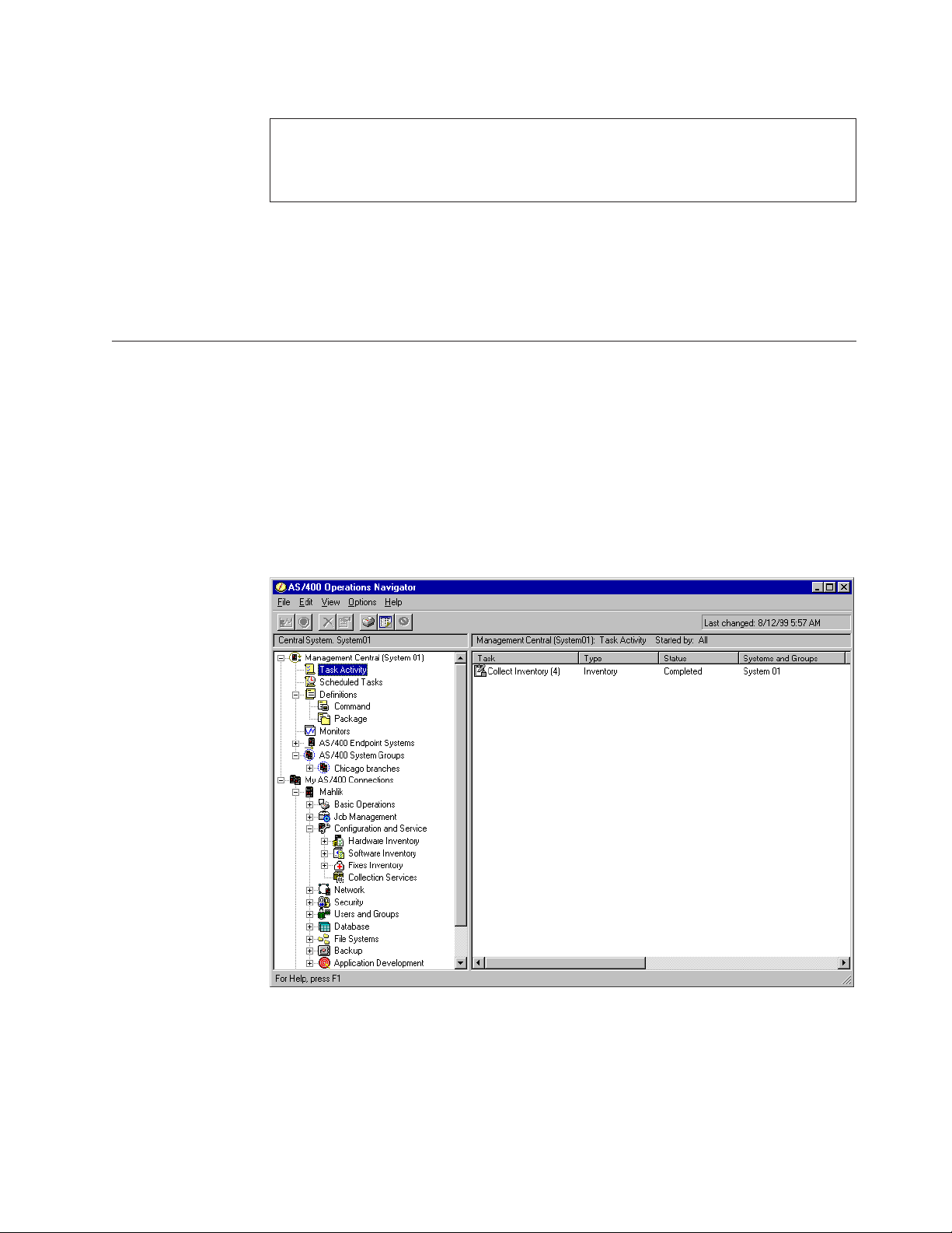
AS/400 Operations Navigator
AS/400 Operations Navigator is a powerful graphical interface for Windows
clients. With AS/400 Operations Navigator, you can manage and administer your
AS/400 systems from your Windows desktop.
You can use Operations Navigator to manage communications, printing, database,
security, and other system operations. Operations Navigator includes Management
Central for managing multiple AS/400 systems centrally.
Figure 1 shows an example of the Operations Navigator display:
Figure 1. AS/400 Operations Navigator Display
This new interface has been designed to make you more productive and is the
only user interface to new, advanced features of OS/400. Therefore, IBM
recommends that you use AS/400 Operations Navigator, which has online help to
guide you. While this interface is being developed, you may still need to use an
emulator such as PC5250 to do some of your tasks.
AS/400e 940x RISC-to-RISC Road Map, SA41–5155–04 vii
Page 10

Installing Operations Navigator
To use AS/400 Operations Navigator, you must have Client Access installed on
your Windows PC. For help in connecting your Windows PC to your AS/400
system, consult Client Access Express for Windows - Setup, SC41-5507-01.
AS/400 Operations Navigator is a separately installable component of Client
Access that contains many subcomponents. If you are installing for the first time
and you use the Typical installation option, the following options are installed by
default:
v Operations Navigator base support
v Basic operations (messages, printer output, and printers)
To select the subcomponents that you want to install, select the Custom installation
option. (After Operations Navigator has been installed, you can add
subcomponents by using Client Access Selective Setup.)
After you install Client Access, double-click the AS400 Operations Navigator icon
on your desktop to access Operations Navigator and create an AS/400 connection.
Information Available on the World Wide Web
You can use the associated uniform resource locator (URL) address to access the
following items on the World Wide Web:
v AS/400 Information Center
http://www.as400.com/infocenter
http://publib.boulder.ibm.com/pubs/html/as400/infocenter.htm
You can use the AS/400 Information Center as a starting point for your AS/400
information needs. It contains browsable information on important topics such
as Java, program temporary fixes (PTFs), and Internet security. It also contains
hypertext links to related topics, including Internet links to Web sites such as the
AS/400 Technical Studio, the AS/400 Softcopy Library, and the AS/400 Homepage.
– AS/400 On line Library
http://publib.boulder.ibm.com/html/as400/onlinelib.htm
– AS/400 Homepage
http://www.as400.ibm.com/
To obtain information for various AS/400 topics, including news and events,
hardware, software, education, certification, reference library, configuration,
case studies, and order status, access AS/400 Homepage.
– AS/400 Technical Studio
http://www.as400.ibm.com/tstudio/
You can use the AS/400 Technical Studio to obtain information about technical
workshops, tools, and technical information to help make your AS/400 run at
its peak.
v AS/400 Year 2000 Support
http://www.as400.ibm.com/developer/year2000/index.html
v AS/400 Internet program temporary fix (PTF) Downloads
http://as400service.ibm.com
viii AS400e 940x RISC-to-RISC Road Map V4R5
Page 11

This Web site allows worldwide customers to order or download AS/400 PTFs
over the Internet. You need to register at this site. Do the following to go to the
AS/400 Internet PTF Facility:
1. Click Fixes, Downloads and Updates
2. Click Internet PTF Downloads (iPTF)
v Site Preparation Web site
http://www.as400.ibm.com/tstudio/planning/plngstrt.htm
This site is essential in setting up the space, power, and environment for a new
AS/400 or for an upgrade to a current AS/400.
Prerequisite and Related Information
Use the AS/400 Information Center as your starting point for looking up AS/400
technical information. You can access the Information Center from the AS/400e
Information Center CD-ROM (English version: SK3T-2027) or from one of these
Web sites:
V4R5
http://www.as400.ibm.com/infocenter
V4R3 or V4R4
http://publib.boulder.ibm.com/pubs/html/as400/infocenter.htm
The AS/400 Information Center contains advisors and important topics such as CL
commands, system application programming interfaces (APIs), logical partitioning,
clustering, Java, TCP/IP, Web serving, and secured networks. It also contains
Internet links to Web sites such as the AS/400 On-line Library, AS/400 redbooks,
and the AS/400 Technical Studio.
For more in depth information about working with PTFs, see the book Basic System
Operation, Administration, and Problem Handling, SC41-5206-04.
Your RISC-to-RISC upgrade or data migration requires the following publications:
v This book. The online version of this book is at the following Web site:
http://www.as400.ibm.com/tstudio/tech_ref/rrmap/index.htm
|
|
|
|
|
|
|
|
|
|
|
|
|
|
|
v Preventive Service Planning (PSP) information. This provides information about
problems you may encounter as you install V4R5 or upgrade your system. You
can download PSP information from the following Web site:
www.as400service.ibm.com/supporthome.nsf/Document/10000031
The PSP identifier for information that pertains to system upgrades and data
migrations is SF98163. Alternatively, you can obtain PSP information from your
software service provider.
Information within this PSP describes known high-impact and pervasive
problems. Review this PSP information before you upgrade your system or
migrate your data between systems. To receive this PSP information by using
ECS, type the following command on an iSeries command line:
SNDPTFORD SF98163
v AS/400 Memorandum to Users. This book describes the changes in Version 4
Release 5 Modification 0 (V4R5M0) that could affect your programs or system
operations. This information also helps you to prepare for changes on your
AS/400e 940x RISC-to-RISC Road Map, SA41–5155–04 ix
Page 12

|
|
current system and to use the new release. You can view or print the PDF
version of the Memo to Users from the home page of the Information Center.
v AS/400 Information Center, SK3T-2027-03 is required for logical partition
information along with many other topics.
v Software Installation, SC41-5120-04 is required for the software upgrade.
v Physical Planning Reference at the following Web site:
http://www.as400.ibm.com/tstudio/planning/plngstrt.htm
v AS/400 Technical Studio has information covering many topics which you may
find valuable. You can access AS/400 Technical Studio at the following Web site:
http://www.as400.ibm.com/tstudio/index.htm
v Basic System Operation, Administration, and Problem Handling, SC41-5206-04
v Backup and Recovery, SC41-5304-04 is no longer shipped with a new system and
should be ordered prior to an upgrade.
The Backup and Recovery book is available in the AS/400 Information Center,
SK3T-2027-03 and is shipped with your order.
|
|
|
|
|
|
|
v The Performance Capabilities Reference. This reference contains information for
customers who plan to upgrade their systems and software. This reference also
provides highly technical information about system performance useful for
performance benchmarking, capacity planning, and planning for system
performance. You can view or print the PDF version of this reference at the
following Web site:
http://www.ibm.com/servers/eserver/iseries/perfmgmt/resource.htm
|
|
|
|
|
|
For additional information related to upgrades or data migration, see the
following:
v The Migration Web site at
http://www.ibm.com/eserver/iseries/migration
v The Upgrade Planning Web site at
http://www-1.ibm.com/servers/eserver/iseries/support/planning/nav.html
For information about other AS/400 publications (except Advanced 36), see the
following:
v Prior to V4R4, the Publications Reference, SC41-5003, in the AS/400 Softcopy
Library.
v The AS/400 Information Directory is a unique, multimedia interface to a
searchable database. It contains descriptions of titles available from IBM or from
other selected publishers. It comes with the OS/400 operating system at no extra
charge.
v The AS/400 On line Library is available on the World Wide Web. See “Information
Available on the World Wide Web” on page viii.
An upgrade might require the use the following publications:
v Operations Console Setup, SC41-5508-01
v BEST/1 Capacity Planning Tool, SC41-5341-00
v LPS: OnDemand for AS/400, GC41-5079-01
v OptiConnect for OS/400, SC41-5414-02
For information about other AS/400 publications (except Advanced 36), see The
AS/400 Softcopy Library.
x AS400e 940x RISC-to-RISC Road Map V4R5
Page 13

How to send your comments
Your feedback is important in helping to provide the most accurate and
high-quality information. If you have any comments about this book or any other
AS/400 documentation, fill out the readers’ comment form at the back of this
book.
v If you prefer to send comments by mail, use the readers’ comment form with the
address that is printed on the back. If you are mailing a readers’ comment form
from a country other than the United States, you can give the form to the local
IBM branch office or IBM representative for postage-paid mailing.
v If you prefer to send comments by FAX, use either of the following numbers:
– United States, Canada, and Puerto Rico: 1-800-937-3430
– Other countries: 1-507-253-5192
v If you prefer to send comments electronically, use one of these e-mail addresses:
– Comments on books:
RCHCLERK@us.ibm.com
– Comments on the AS/400 Information Center:
RCHINFOC@us.ibm.com
Be sure to include the following:
v The name of the book.
v The publication number of the book.
v The page number or topic to which your comment applies.
AS/400e 940x RISC-to-RISC Road Map, SA41–5155–04 xi
Page 14

xii AS400e 940x RISC-to-RISC Road Map V4R5
Page 15

Chapter 1. Overview of RISC-to-RISC Upgrades and Data Migrations
The road map lists important considerations and activities that are critical to the
successful model upgrade of a system. Although this road map is not designed to
be an all inclusive how-to source for activities relating to upgrading your system, it
covers the essentials by guiding you to the proper source. Follow all the steps in
the order presented and notify your IBM
into difficulties.
®
representative for assistance if you run
|
|
|
|
|
|
|
|
This information does not specifically cover hardware feature upgrades for the
following features:
v Feature conversion 5065 to 5074
v Feature conversion 5066 to 5079
v Feature conversion 5075 to 5074
If you are performing one of these hardware feature upgrades in a partitioned
environment, see the Logical Partitioning web site at the following address:
http://www-1.ibm.com/servers/eserver/iseries/lpar/
This road map also covers how to perform a model to model data migration. A
data migration can be performed from almost any model AS/400
AS/400. The source model must be at the same release as the new model AS/400
to correctly complete the data migration.
What Is In this Road Map
This road map covers the following upgrades:
Notes:
1. The source system might need a hardware upgrade before the customer starts
Program Temporary Fixes (PTFs) and prior to installing V4R4 or V4R5
software. This is to get the source system compatible with the target system.
7xx models require V4R3 or later and 8xx models require V4R5.
2. SSP is not supported in V4R5.
v Model 170 to Model 170
There are no upgrades into or out of a model 170. The Data Migration section of
this book covers the procedure used to perform a data move from the source
system to the new model AS/400.
v Model 270 to Model 270
There are no upgrades into or out of a model 270. The Data Migration section of
this book covers the procedure used to perform a data move from the source
system to the new model AS/400.
v Models 5xx to Models 7xx
v Models 6xx to Models 7xx
v Models 7xx to Models 7xx
v Models Sxx or 5xx to Models 8xx
There are no model upgrades into a model 8xx from a model 5xx, SB1, SB2, or
SB3. However, some hardware may be moved from the 5xx into a migration I
®
to any model
© Copyright IBM Corp. 1997, 2000 1
Page 16

expansion unit (I/O and disk unit). The Data Migration section of this book
covers the procedure used to perform a data move from the source system to the
new model AS/400.
v Models 6xx to Models 8xx
v Models 7xx to Models 8xx
v Models 8xx to Models 8xx
Appendix C, “Possible AS/400 RISC-to-RISC Upgrades” on page 45 has detailed
tables that indicate which upgrades are permitted.
For servers not having an upgrade path, use the data migration section of this
book. This would include scenarios such as, an AS/400 model 540 to an AS/400
model 270.
|
|
|
|
|
|
|
|
This information does not specifically cover hardware feature upgrades for the
following features:
v Feature conversion 5065 to 5074
v Feature conversion 5066 to 5079
v Feature conversion 5075 to 5074
If you are performing one of these hardware feature upgrades in a partitioned
environment, see the Logical Partitioning web site at the following address:
http://www-1.ibm.com/servers/eserver/iseries/lpar/
Why Upgrade from One AS/400 System to Another?
You might ask yourself why IBM is doing this and why upgrade your system
now? Most customers need to increase performance and add capacity.
What is An Upgrade?
In this book, an upgrade is any improvement made to the software or the
hardware of an AS/400 model that retains the serial number of the AS/400 model.
This includes moving the compatible hardware, the Licensed Internal Code,
operating system, and the licensed programs to a new target system for better
performance and reliability.
A data migration is the process of moving only the data from one model AS/400
to a new model AS/400.
Hardware Investment for Upgrading
You may choose to upgrade your existing AS/400 RISC system processor, or
replace it with a new, AS/400 model. In either case, you may keep most of the
current system. The process of either an upgrade of your existing system or
moving parts from an existing system to a new system, are called miscellaneous
equipment specification (MES). A MES is the process steps of an upgrade. The
type of MES depends on several factors:
v Your current processor model
v Costs
v Your system availability requirements
The information in this book will help to determine the right path to an upgrade.
This is based on the current model and the goals of the process.
2 AS400e 940x RISC-to-RISC Road Map V4R5
Page 17

How Long Will the Upgrade Take?
The upgrade process includes planning, ordering, shipping, installing and testing
the system. The following table shows approximately how long an upgrade might
take.
Note: You should plan at least one additional hour of down time to load the
operating system for systems not preloaded.
Order Planning - 5 to 15
Days
See “Prerequisite and
Related Information” on
page ix for required
publications.
System Requirements Solution Assurance Upgrade Software Verify System
Performance Hardware and Software
Determine Services
Needed
Place Order
Installation Planning and Preparation - 10 to 30 days Phase II Installation - Weekend
(1 to 3 days)
Save System
See “Prerequisite and
Related Information” on
page ix for required
publications.
Preparation
Physical Planning (Site
Preparation)
Phase I Installation - 5 to
20 Days
Save System Upgrade Hardware
Check History and Clean
Up Messages
Save System
What is A Data Migration?
A data migration is the process of moving the OS/400®and the data from one
model AS/400 to a new model AS/400.
The source system must be at the same release level as the target server. This
includes OS/400, all objects, and all licensed programs.
For customers ordering a new RISC AS/400 server with V4R4 or V4R5 to replace
an existing RISC AS/400 model (″source″) and needing to migrate their data from
the ″source″ model to the new server, a new feature code Feature Code (F/C)
#0205, is now available. This new feature code should be ordered against the new
RISC AS/400 server. It is valid on orders for all new servers except the Models 150
and SB1.
For Feature Code #0205, the customer must have purchased a new server with
enough hardware and disk unit to hold all of the data from the ″source″ model as
well as any new data including any required IBM software (OS/400 and so forth).
Additionally, the RISC-to-RISC Data Migration process requires that the ″source″
model must be at the same version/release of OS/400 and Licensed Program
Products (LPPs) as that of the ″new″ server which has been ordered/received.
Customers with Version 3 (V3R7) on their ″source″ model must upgrade to Version
4. It is recommended that they purchase Software Subscription for AS/400. They
must then order and upgrade to match the new server (V4R4 or V4R5) in order to
proceed with their data migration. V3R7 cannot be directly upgraded to V4R4 or
V4R5 therefore, to do this the source system will need to be upgraded to V4R2 or
V4R3 before upgrading to V4R4 or V4R5. Customers with Version 4 must obtain
new server release of OS/400 licenses of the LPPs, either through new orders or
via Software Subscription for AS/400.
Chapter 1. Overview of RISC-to-RISC Upgrades and Data Migrations 3
Page 18

A License Addendum will be provided to allow the customer to install and use the
copy of OS/400 (received with the newly ordered server) on their source model for
up to 70 days. This Addendum authorizes the customers to use the new Version
and Release on the source system for the sole purpose of migrating their data. The
previous Version and Release must be reinstalled after the migration is completed.
The V4R4 or V4R5 licenses of OS/400 and the LPPs will only allow the products to
be run on one system at a time. Model 150 customers who are not at the new
server release of OS/400 must purchase the BasePak Upgrade (5649-EP5 for V4R4)
in addition to any upgrades for installed Optional Products in order to proceed
with their data migration. Feature Code #0205 provides for minimal pre loading of
the new server, inclusion of a special License Addendum, and an insert which
points to the AS/400 Technical Studio Web site (which provides the RISC-to-RISC
Road Map):
http://www.as400.ibm.com/tstudio/tech_ref/rrmap/
This Road Map provides the steps on how to do the RISC-to-RISC data migration.
For subsequent releases of OS/400, the Road Map will be included with the
shipment of the new server. Feature Code #0205 differs from Feature Code #0203.
Feature Code #0203 SHOULD NOT be ordered for AS/400 RISC-to-RISC data
migrations as it is designed exclusively for AS/400 CISC-to-RISC data migrations.
How Long Will the Data Migration Take?
The data migration process includes planning, ordering, shipping, installing and
testing the system. The following table shows approximately how long a data
migration might take.
Note: You should plan at least one additional hour of down time to upgrade the
operating system for source systems not at the new server release level.
Order Planning - 5 to 15 Days Installation Planning and
Preparation - 10 to 30 days
See “Prerequisite and Related
Information” on page ix for
required publications.
System Requirements Solution Assurance Verify System
Performance Physical Planning (Site
Determine Services Needed Software Preparation (Upgrade
Place Order Save System
See “Prerequisite and Related
Information” on page ix for
required publications.
Preparation)
Source System Software)
Phase II Installation - Weekend (1 to 3
days)
Migrate Data
Check History and Clean Up Messages
Save System
Books to Use for Software Release Upgrades
The following table lists software release considerations, and which book to use for
upgrading the operating system and licensed programs.
4 AS400e 940x RISC-to-RISC Road Map V4R5
Page 19

OS/400 Release Currently Installed Book To Use For Upgrade and Software Installation
V4R5
V4R4
V4R3
V4R2
V4R1
V3R7
V3R7 and V4R1*
If you have one of these releases installed on your system, your system
already runs on the RISC architecture. Use this book (AS/400e 940x
RISC-to-RISC Road Map, SA41-5155-04) for the upgrade. Use the book
Software Installation, SC41-5120-04, to replace the installed operating system
and licensed programs. Use the book Backup and Recovery, SC41-5304-04, for
the save and restore requirements of these procedures.
Note: * You cannot upgrade directly from V3R7 to V4R4 or V4R5. You must
first upgrade V3R7 to V4R2 or V4R3.
Note: * You cannot upgrade directly from V4R1 to V4R5. You must first
upgrade V4R1 to V4R3 or V4R4.
Note: V4R4 introduced logical partitions. Go to the Information Center for
help with setting up, upgrades to and maintaining logical partitions.
See the Software Installation book for other software requirements and
limitations prior to the OS/400 upgrade.
The Backup and Recovery book is now located in the AS/400 Information
Center, SK3T-2027-03.
Chapter 1. Overview of RISC-to-RISC Upgrades and Data Migrations 5
Page 20

6 AS400e 940x RISC-to-RISC Road Map V4R5
Page 21

Chapter 2. Planning Your Order for Upgrading or Data Migration
Review this chapter as you identify a solution and again after a decision is made
to verify the accuracy and completeness of the order.
Determining Your Upgrade Needs
To help determine the upgrade needs, please consider the following:
v What problems does this upgrade need to address?
v What additional applications or growth do you expect or plan for in the future?
v What new technology do you want as part of the upgrade?
v What are the requirements are for the following:
– Capacity
– Capability
– Performance
– Availability
v What are your expectations for the following:
– Impact on business operations
– Cost
– Performance
v What are the financial considerations to keep in mind? For example:
– Government discounts
– Capital planning cycles
– Tax implications
– Budget
Performance Tools for Capacity Planning and Performance Analysis
|
|
|
|
© Copyright IBM Corp. 1997, 2000 7
The Performance Capabilities Reference provides information on iSeries
performance, capacity planning, and tips to obtain best performance. You can view
or print the PDF version of this reference at the following Web site:
http://www.ibm.com/servers/eserver/iseries/perfmgmt/resource.htm
The licensed program Performance Tools/400 (Program 57xx-PT1) and QSIZE400
on the AS/400 configurator can be used for capacity planning and performance
analysis.
The BEST**/1 Capacity Planning function of the Performance Tools licensed
program provides the capability to analyze how a different AS/400 configuration
will perform with your current work load. The program temporary fixes (PTFs) are
now available that include capacity planning information for the PowerPC
processor models of the system. You can use Performance Tools to help you
determine the proper configuration of the processor main storage, and disk
resources that will meet your performance requirements.
Page 22

Performance Tools are the best source of information for determining what
configuration meets your performance requirements. You should order the PTF
that updates your version of Performance Tools with the PowerPC AS processor
models.
Note: If you do not have Performance Tools on your system, you should obtain
modeling information in another way, such as by using consulting services.
Modeling the characteristics of your target configuration helps ensure that
the configuration meets your needs.
The latest PTFs for AS/400 BEST/1 Capacity Planner are required. You can order
or download these PTFs from the following Web site:
http://as400service.ibm.com
You need to register at this site. Do the following to go to the AS/400 Internet PTF
Facility:
1. Click Fixes, Downloads and Updates
2. Click Internet PTF Downloads (iPTF)
How to Gather Configuration Information
You and your marketing representative use the Enhanced Upgrade Order Process
(EUOP) and the AS/400 configuration program (CPAS400 and e.Config). This
process compares your current configuration with your desired configuration and
creates the MES order automatically. This simplifies the work that you and the
marketing representative have to do and ensures a correct MES order. See
Appendix B, “Enhanced Upgrade Order Process (EUOP)” on page 43 for more
information on how to use the Enhanced Upgrade Order Process.
How to Gather Performance Information
Gathering performance data before installing a release gives you a base with which
to compare your system’s performance after the installation is complete.
Performance data is also useful when determining the correct hardware
configuration for your upgrade.
You can gather the information by using the Start Performance Monitor
(STRPFRMON) command or the Work with Performance Collection
(WRKPFRCOL) command.
If you use the STRPFRMON command or WRKPFRCOL command, you should
collect two sets of data. The first set of performance data should be an overview
for a 24-hour period. Collect two 24-hour periods on days when the system load is
normal to heavy.
See the Software Installation book for more information on performance
monitoring.
Note: If you plan to install the Version 4 licensed program 5769-PM1, you must
convert the data collected on your current pre-Version 4 system before you
can analyze it with the 5769-PM1 licensed program.
8 AS400e 940x RISC-to-RISC Road Map V4R5
Page 23

Prerequisites Before Placing an Order
This section will cover the prerequisites of placing an order to upgrade the system.
These include software-related items, hardware considerations, system
configuration considerations, and available services that everyone should know
before placing an order.
Version 4 Software Items
See the table on supported releases for software upgrades in the book Software
Installation, SC41-5120-04, to find what versions may be upgraded from and to. For
example, you must be at V4R1 to upgrade to V4R4 and at V4R2 to upgrade to
V4R5.
The ″Preparation Program Temporary Fixes Required Before Installing V4R5M0
Software″ section in the Software Installation book describes how to apply PTFs.
Other Software Related Items
v Determine whether there are any additional software charges that are associated
with the processor group change. Two passes must be run on the AS/400
configuration program to determine these changes.
v Determine whether there are any additional usage changes because of the
user-based pricing that is associated with the software products on the system.
v Verify with the software service representative, or the business partner, that any
third party software that you use was tested on the software release level
ordered.
v Contact the software service representative for any software considerations and
restrictions that might apply to the model upgrade.
Notes:
1. If you have tape management software, ensure that it uses support that is
available on your target system. Do the following:
a. Type DSPOBJD OBJ(QSYS/QUSTAPEX) OBJTYPE(*PGM)
b. If you receive the message Object QUSTAPEX in library QSYS type *PGM
not found, you do not have this potential problem with tape management
software.
c. If you see the Display Object Description display for the QUSTAPEX
program, press F12 (Cancel). Contact the vendor who supplies your tape
management software to determine how the vendor will provide equivalent
support for your target release.
You may need to order an OS/400 feature called MSE (Media and Storage
Extensions).
2. For other software related questions, see AS/400 Technical Studio and the book
Software Installation, SC41-5120-04.
Attention:
®
For V4R4, OS/400 option 24 (OS/400 Lotus
longer supported. It is deleted when V4R4 is installed. A migration of the data
must occur prior to installing V4R4 to Lotus Domino
instructions refer to the following URL:
Notes™Enhanced Integration) is no
™
for OS/400. For detailed
http://www.as400.ibm.com/techstudio
Chapter 2. Planning Your Order for Upgrading or Data Migration 9
Page 24

Hardware Considerations
v Determine the prerequisite engineering changes and program temporary fixes
(PTFs) that are needed to upgrade the system.
v Determine the attached input-output devices, and the operating system.
v Verify with the original equipment manufacturer vendor that any non-IBM
devices are compatible with the model upgrade and the new software release.
Note: The customer should request written confirmation of this compatibility
from the original equipment manufacturer vendor.
v The target system may have different power requirements than the source
system. Appropriate planning and preparation by the customer is very
important. Determine whether you need additional space and power
requirements for any additional system units or system racks. For more
information, see the AS/400 Technical Studio.
v Verify that the target system has a tape drive compatible with the tape format
used to save information on the source system.
v Ensure that your marketing representative or IBM business partner is aware of
the number of ports on your current twin-ax workstation controllers and the
number of ports you will need on your new model. This will help to ensure that
the proper model and features get ordered for your upgrade.
Installing from an Alternate Installation Device
Version 4 releases include support for alternate installation devices on buses other
than bus 1 (the system bus). If you use an alternate installation device, you need to
ensure that the device is set up and enabled. You also need to have the CD-ROM
for Licensed Internal Code as well as your tape media. The Appendix of the
Software Installation book describes the alternate installation device function and
identifies situations in which older tape devices may require its use. The appendix
also describes how to set up, enable, or disable an alternate installation device.
Note:
alternate IPL device
This may be a CD-ROM unit or tape unit, attached to the system
bus 1 (the system bus)
alternate installation device
Tape unit attached to a bus other than the system bus 1
Performing the IPL using the alternate installation method is really just a
special kind of IPL type D. Such an installation involves two pieces of
media: the alternate IPL load source (code), usually on a CD-ROM, and the
alternate installation media (currently must be a tape). The alternate IPL
load source is used to start the IPL type D. The alternate installation media
contains the Licensed Internal Code that will be installed on the system. The
alternate IPL load source will always be read through a device on bus 1 of
the system. The alternate installation media is placed in a device on any bus,
except bus 1.
System Configuration Considerations
v Change the auxiliary storage pool (ASP) configuration either before or after the
upgrade, but never during the upgrade.
v If you use mirroring, make sure to specify the correct level.
10 AS400e 940x RISC-to-RISC Road Map V4R5
Page 25

v A current system configuration list should be available for the hardware service
representative. The configuration list provides details of your current system
configuration.
To print the System Configuration List, do the following:
1. On the AS/400 Main menu command line, type STRSST. Then, press the Enter
key.
2. On the STRSST display, select Start a service tool option. Press the Enter key.
3. On the Start a Service Tool display, select Hardware service manager. Press
the Enter key.
4. From the Hardware Service Manager display, press F6 (print configuration).
5. To return to the AS/400 Main menu, Press F3 (Exit) twice, and then press the
Enter key.
6. Keep the printed list - the service representative will need it.
Services and Other Assistance
v Determine whether you need on-site support or services. Appendix A, “AS/400
Global Services” on page 39, has information about the following:
– IBM Global Services
– AS/400 Data Migration Services
– V4R5 Planning and Migration Services
– LPAR Planning and Implementation Services
– Other AS/400 support family services
– AS/400 solution services
v Determine the responsibilities for all upgrade activities. These responsibilities
include:
– Outline the model upgrade activities and the person responsible for each
activity, as described in Table 4 on page 19.
– Develop an installation plan, a schedule of activities, and a checklist. See the
SA Advisor in the Expert menu Application on HONE.
Your IBM Representative may visit the Solutions Assurance Web site:
http://w3.ibm.com/support/assure
Your IBM representative can use marketing tools to get more information
about these changes:
On a Virtual Machine (VM) system type:
TOOLS SENDTO LEXVMIC1 TOOLS SAPRDOC GET SA95008 SCRIPT *
TOOLS SENDTO LEXVMIC1 TOOLS SAPRDOC GET SA95008 LIST3820 *
v Order any optional hardware and software publications by using PUBORDER or
the System Library Subscription Service (SLSS).
v Determine whether you have any education needs.
Model-specific Considerations for Placing an Order
There are unique model-specific considerations when upgrading from one RISC
model to another RISC model. Before placing an order, everyone involved in the
upgrade process should review these upgrade considerations:
Note: IBM refreshed some of the AS/400 input and output adapter lines in V4R1.
The Peripheral Component Interconnect (PCI) is now an industry standard.
Chapter 2. Planning Your Order for Upgrading or Data Migration 11
Page 26

Version 3 software users may have some System Product Division (SPD)
hardware that is not supported by these PCI changes. Your IBM
representative can use marketing tools to get more information about these
changes:
On a VM system type:
TOOLS SENDTO USDIST MKTTOOLS MKTTOOLS GET PCIALT PACKAGE
v The prerequisite for migrating SPD book-type adapter cards is a Model S20, S30,
S40, SB1, 620, 640, 650, 720, 730, or 740.
v There is concurrent disk unit maintenance.
v You must upgrade any 266 MB expansion unit to 1063 MB.
v You can use the alternate IPL device (see “Installing from an Alternate
Installation Device” on page 10) function for any installation or recovery that
requires replacing Licensed Internal Code or other licensed programs. Some
models might require an alternate installation device. You can use this device
for installing distribution tapes that were created by a central site, or for
recovery, using a SAVSYS tape.
Note: In Models S10, S20, 600, 620 and 720, the input-output processor (IOP) to
which certain older tape devices connect, require an expansion unit in
order to use the devices. The following tape devices are affected: 2440,
3422, 3430, 3480, 9347, 7208-002, and some models of 3490. Other 7208
models and 3490 models Exx, C11, and C22 are supported without an
expansion unit. Models 3490 C1A and C2A can be converted to Small
Computer Systems Interface (SCSI) format, which is supported without an
expansion unit. If you use older tape devices as alternate installation
devices, on Models S10, S20, 600,620 and 720, you need the expansion
unit. You need to set up the devices as alternate installation devices.
v Models Sxx and 6xx have a new internal-external SCSI input-output adapter.
v You cannot upgrade an AS/400 Advanced Series to an AS/400 Advanced Server.
You cannot update an AS/400 Advanced Server to an AS/400 Advanced Series.
v Be aware that upgrades to an AS/400 may require wiring changes to the
building. For more information, see the AS/400 Technical Studio.
The customer should work with the marketing representative to schedule a
system assurance meeting to review all of the following activities.
Note: This meeting should include the customer, IBM marketing representative,
hardware service representative, software service representative, and any
non-IBM software service representative.
v Review memory considerations as follows:
– Net-priced main storage feature exchanges are not available when upgrading
to another AS/400 PowerPC AS model. In addition, you cannot exchange
AS/400 memory cards for credit toward the purchase of newer or larger
AS/400 memory cards. To reduce the necessity for future memory exchanges,
the customer should order sufficient memory card sizes for future growth
requirements.
– Main storage for AS/400 400
– Main storage for AS/400 40S, 50S, and 53S, are not compatible with each
other.
– You must plug in main storage cards in equally-sized pairs for the Model 500
Feature Processor 2142. Therefore, it might not be possible to reuse all of the
main storage cards from the previous feature processor (2140 or 2141).
12 AS400e 940x RISC-to-RISC Road Map V4R5
®
, 500, and 530 is not compatible with each other.
Page 27

– You must plug in main storage cards in equally-sized pairs for the AS/400
510 and 530 and the AS/400 50S and 53S.
v Ensure that you know how to accomplish RAID protection on a migrated
internal disk unit. You must have an attachment to a Feature Code for a high
availability DASD controller (for example, 6502, 6512, 6532, 2726,or2740).
Note: In order to avoid additional charges for the IBM service representative’s
time, perform ASP management after completion of the hardware
upgrade.
v Be prepared to delete the old device description and create a new one, if the
type of console changes.
v Review and confirm the hardware and software order.
v Some systems have a mix of unsupported disk unit devices. If the system has
such a mix, consider one of the following:
– Purchase additional supported disk unit devices in order to enable the
removal of all unsupported devices before the model upgrade.
– Purchase AS/400 Data Migration Services.
Upgrading from a 4xx, 5xx, Sxx, or 6xx to a 7xx
Many installed AS/400 models 4xx, 5xx, 6xx, and Sxx (except SB1) can be
upgraded.
All system units and expansion units have locations for features including
processors, main storage, power, expansion units, disk units, tape drives, CD-ROM
drive, and IOPs. Some restrictions may apply to certain combinations of features.
The configurator contains the rules and performance considerations for placement
of these features. It should be used to ensure a valid configuration. The use of
performance tools may also help in optimizing a configuration to match a specific
set of requirements.
Note: When ordering a model upgrade from a mixed-mode server (S20, S30, S40)
to AS/400e
™
7xx servers, an Interactive Specify code must be on the model
Sxx inventory record prior to ordering the model upgrade. The configurator
will generate a Record Purpose Only (RPO) order to add a zero priced
Interactive Specify code to the installed mixed-mode server prior to the
upgrade. This is a required step.
Sxx Interactive Specifies that the configurator will add:
v Model S20
– #1490 Interactive Specify
– #1492 Interactive Specify
v Model S30
– #1492 Interactive Specify
– #1493 Interactive Specify
– #1494 Interactive Specify
v Model S40
– #1495 Interactive Specify
– #1496 Interactive Specify
Chapter 2. Planning Your Order for Upgrading or Data Migration 13
Page 28

Dedicated Server for Domino
The Dedicated Server for Domino supports the following 170 processors:
v 2407 based on the 2292 model 170 processor
v 2408 based on the 2385 model 170 processor
v 2409 based on the 2388 model 170 processor
The Dedicated Server for Domino supports the following 270 processors:
v 2422 based on the 2250 model 270-2
v 2423 based on the 2252 model 270-3
v 2424 based on the 2253 model 270-4
The Dedicated Server for Domino supports the following 8xx processors:
v 2425 based on the 2396 model 820-2
v 2426 based on the 2397 model 820-3
v 2427 based on the 2402 model 830-2
v 2428 based on the 2403 model 830-3
MES upgrades to the Dedicated Server for Domino will not be allowed. Dedicated
Server for Domino models may optionally be preloaded with Domino for AS/400
software and license. Dedicated Server for Domino server is a prerequisite for a
Domino for AS/400 Quarterly Maintenance Update (QMU) version 5.01x.
Dedicated Server for Domino will give favored performance to workloads running
Domino and non-favored performance to workloads not running Domino.
Interactive jobs will also be restricted.
For more information refer to the topic ″Domino for AS/400 Server″ in the AS/400
Information Center.
Migrating from a 5xx to an 8xx
When migrating SPD expansion units from a model 5xx or from any unsupported
path to an 8xx server, the order must have a migration expansion unit included.
IBM does not provide a pre-planned or pre-programmed upgrade from a Model
5xx to a Model 8xx. The user who wants to move I/O to 8xx hardware will have
to analyze their current configuration and determine what will and will not move
and plan the sequence of actions to make it happen. Here are some general
considerations:
v SPD I/O expansion unit can not be directly attached to an 8xx. A migration
expansion unit with SPD capability is required. If you have a Model 830 or 840
and do not have a migration expansion unit yet, a migration expansion unit
(migration expansion unit II), FC #5077 (and perhaps an FC #5057 expansion
unit), should be ordered. IBM does not offer an option to order a migration
expansion unit (migration expansion unit I) which could attach to a 820.
v SPD IOPs can not be inserted into an 8xx except via SPD slots in a migration
expansion unit or in SPD I/O expansion unit attached via a migration expansion
unit.
v Not all I/O is supported by V4R5 on an 8xx. There were several older disk
units, tape drives, IOPs, and so forth, which were no longer supported as of
V4R1.
14 AS400e 940x RISC-to-RISC Road Map V4R5
Page 29

v The I/O expansion unit, on a model 500 or 510 only has a 266 Mbps Optical bus
Adapter which is too slow for the migration expansion unit to support. Using
the S40388 RPQ, the expansion unit can be converted to a faster I/O expansion
unit with a 1063 Mbps Optical Bus Adapter.
v In V4R5, the only type of PC console that an 8xx system supports is Operations
Console.
v Planning assistance from IBM Global Services or from an IBM Business Partner
may be very helpful if this is an unfamiliar area to the customer.
Upgrading from a 6xx or 7xx to an 8xx
Many installed AS/400 models 6xx and 7xx, except SBx, can be upgraded to the
8xx servers. See “Upgrading to a New 7xx or 8xx Model” on page 46 for
information on supported upgrades to new AS/400 models.
8xx models require V4R5 versions of OS/400.
All system units and expansion units have locations for features including
processors, main storage, power, expansion units, disk units, tape drives, CD-ROM
drive, and IOPs. Some restrictions may apply to certain combinations of features.
The configurator contains the rules and performance considerations for placement
of these features. It should be used to ensure a valid configuration. The use of
performance tools may also help in optimizing a configuration to match a specific
set of requirements.
Placing the Upgrade Order
After you have identified what is necessary for the upgrade, continue with the
following sections:
Who is Responsible for Ordering the Upgrade?
The following tables show a check-off sequence for tasks during the ordering
process.
Note: IBM Services personnel may perform the customer activities for a fee.
Table 1. Tasks and Responsibilities for Ordering
Checkoff Tasks and Responsibilities for Ordering Person Responsible
Understand objectives and needs Marketing Representative
Know existing system. Print system
configuration list.
Use the AS/400 Configurator Marketing Representative, Business Partner
Determine prerequisites Marketing Representative, Business Partner,
Determine current running release Marketing Representative, Business Partner,
Determine release-level requirements before
model upgrade
Determine responsibilities Customer Account Team Leader
Determine documentation and education
needs
Determine physical needs Customer, Business Partner
Marketing Representative, Customer
Software Service Representative
Customer
Marketing Representative, Business Partner
Marketing Representative, Business Partner
Chapter 2. Planning Your Order for Upgrading or Data Migration 15
Page 30

Table 1. Tasks and Responsibilities for Ordering (continued)
Checkoff Tasks and Responsibilities for Ordering Person Responsible
Determine special needs (for example,
mirroring)
Determine upgrade path Marketing Representative, Business Partner,
Table 2. Tasks and Responsibilities for Ordering Software
Checkoff Tasks and Responsibilities for Ordering Person Responsible
Order software release Customer, who may need assistance from a
Order program temporary fixes (PTFs) Customer, who may need assistance from a
Order publications Customer, Marketing Representative,
Table 3. Tasks and Responsibilities for Ordering Hardware
Checkoff Tasks and Responsibilities for Ordering Person Responsible
Order engineering changes Marketing Representative, Business Partner
Run the AS/400 configurator to place the
order
Order publications Marketing Representative, Business Partner
Marketing Representative, Business Partner,
Customer
Customer
Marketing Representative or Business
Partner
Marketing Representative or Business
Partner
Business Partner
Marketing Representative, Business Partner
Contact your local IBM representative or authorized dealer to place the order or
for further assistance.
How to Get Help with the Order
Ordering assistance is available from IBM. When you type GO ORDER on the
command line and press the Enter key, the Request Order Assistance display
appears.
Note: If you need assistance when trying to place an order, you can also use the
Request Order Assistance (RQSORDAST) command to request assistance
from IBM.
Use the Request Order Assistance display as follows:
v Type in your telephone number and your name.
v Verify the accuracy of other contact information.
v Press the Enter key.
v Type a short description of your needs.
v Press F10 (send) to send the file to IBM.
Sending the Order to IBM
The RQSORDAST command can send a list which contains your current AS/400
system configuration, with your order. IBM uses this list to assess your ordering
needs.
16 AS400e 940x RISC-to-RISC Road Map V4R5
Page 31

Sending the Order to a Software Service Provider Other Than IBM
You can send your order request to IBM or to a provider other than IBM. When
you send your order request to a provider other than IBM, you can use the
RQSORDAST command to communicate with the provider. The provider can send
you a response electronically. You can use the WRKORDRQS command to view the
response and manage the order request. The provider will fill your order or
forward your request to IBM.
Chapter 2. Planning Your Order for Upgrading or Data Migration 17
Page 32

18 AS400e 940x RISC-to-RISC Road Map V4R5
Page 33

Chapter 3. Procedure for an Upgrade (RISC-to-RISC)
Who is Responsible for Upgrading the System
The following table establishes a check-off list for task responsibilities in
preparation for and during the upgrade. The list is arranged in the sequence the
tasks should be done.
IBM Services can be provided for additional cost to assist customers.
For customer install systems and servers such as, model 170s, follow the
instructions that came with the system.
Table 4. Tasks and Responsibilities for the Upgrade Path
Checkoff Task Person Responsible
Consider needs for installation Customer, Business Partner, Software
Service Representative, Hardware Service
Representative
Establish tentative installation date Customer and their authorized
representative
Read preventive service planning (PSP) information Customer
Save the system, full save Customer
Install Target Software Release and appropriate PTFs Customer
Verify that all applications are running Customer
Tune performance Customer
Complete physical planning Customer
Save the system, full save Customer
Contact customer Hardware Service Representative and
schedule the upgrade after the order arrives
Verify the following:
v that prerequisite Engineering Changes are installed
v that the customer has installed all required PTFs
v the correct operating system level
v that the customer has backed up the system, including
all customer data
Inventory parts received from IBM as part of the upgrade Hardware Service Representative
Run Work with Hardware Products (WRKHDWPRD)
command option 4
Upgrade hardware using parts shipped from IBM and the
CUII
Save the system, just a system save Customer
Run WRKHDWPRD command option 5 if OS/400 is on
the target system at the completion of the upgrade
Configure extra devices (DASD, for example) Customer
Tune performance Customer
Customer
Hardware Service Representative
Hardware Service Representative
Hardware Service Representative
Customer
© Copyright IBM Corp. 1997, 2000 19
Page 34

Table 4. Tasks and Responsibilities for the Upgrade Path (continued)
Checkoff Task Person Responsible
Perform Redundant Array of Independent Disks (RAID)
and mirroring steps
Save the system, full save Customer
Hold post-installation meeting Customer Account Team Leader
Ensure IBM systems are accurate and updated Marketing Representative
Customer
What to Do When the Hardware Arrives
When the hardware arrives, the customer should notify the hardware service
representative and schedule a time for the upgrade.
Notes:
1. For customer install systems follow the instructions that came with your server
to get set up. If you are replacing an existing system without an upgrade path
covered in Appendix C, “Possible AS/400 RISC-to-RISC Upgrades” on page 45,
use the data migration section of this book.
2. The customer must have at least 64MB of memory or, arrange to have
additional memory installed before the upgrade can proceed. See the Software
Installation book for more information on prerequisites prior to an upgrade.
Check the load source size as follows:
1. Use STRSST (or DST) to do the following:
a. Select ″Work with Disk Units″ option.
b. Select ″Display Disk Configuration″ option.
c. Select ″Display Disk Configuration Capacity″ option.
d. Locate the line displayed for Unit 1. This line shows the protected and
unprotected capacity of the loadsource disk unit. One of the displayed fields
is zero, and one has a size.
2. Write down the size of the loadsource disk unit here- ______________. This
information will be used later in the upgrade.
Preparing the Current System
Approximately two weeks before the hardware service representative arrives, the
customer should do the following:
__ 1. Acquire the preventive service planning information (see Appendix G,
“Obtain the Latest Preventive Service Planning Information” on page 63)
from electronic customer support (see Appendix F, “How to Verify and Set
Up Electronic Customer Support” on page 55) if available, or from the
software service representative.
__ 2. See Appendix E, “Considerations and Solutions” on page 51 for information
pertaining to logical partitions. There are some specific steps to perform for
upgrading a server with a primary and secondary partitions installed.
__ 3. For considerations when upgrading to 5769-RD1 OnDemand, see
Appendix E, “Considerations and Solutions” on page 51 for information for
OnDemand.
20 AS400e 940x RISC-to-RISC Road Map V4R5
Page 35

__ 4. For considerations when upgrading an AS/400 with OptiConnect installed,
see Appendix E, “Considerations and Solutions” on page 51 for information
for OptiConnect.
__ 5. For considerations when upgrading an AS/400 with AS/400 Integrated
Netfinity
®
Server installed, see Appendix E, “Considerations and
Solutions” on page 51 for information for Integrated Netfinity Server.
__ 6. Review and perform all items that pertain to your upgrade situation from
the book Software Installation, SC41-5120-04.
Attention: Do not install the program temporary fix (PTF) that reserves
space for the Version 4 Licensed Internal Code until you ensure that you
have adequate disk space in the system ASP.
__ 7. Document currently installed machine and LPAR partitions.
Without LPAR With LPAR
Skip this step. All hardware must be assigned to a primary
or secondary system partition before
upgrading. Where possible, plan the
upgrade activity in the following stages:
a. Stage 1
Load correct level software and PTFs on
source system, and ensure this is
contained in customer’s save media.
Work with Source system to assign
hardware resources to a partition and
clear non-reporting hardware. Work with
Target system to load customer’s level of
saved Licensed Internal Code onto new
target loadsource. This prevents
down-leveling during the upgrade.
b. Stage 2
Perform the model upgrade and Load
source migration. Do not make any
hardware changes, such as adding SPD
I/O or disk unit expansion units, that
could change the ″bus address distance″
between existing SPD hardware. The
″bus distance″ is important in
maintaining the LPAR configuration.
Note that the SPD hardware bus
addresses are +4 after moving to the
target system (1 maps to 4, 2 maps to 5,
and so on). Clear non-reporting
hardware resources.
c. Stage 3
Add additional features and expansion
units after LPAR configuration has been
re-established.
Contact your next level of support if you have
questions.
__ 8. Display the current value of system value QALWOBJRST and record it here
_______________.
DSPSYSVAL SYSVAL(QALWOBJRST)
__ 9. Set the Allow Object Restore (QALWOBJRST) system value to *All before
you install a new release of OS/400, install new licensed programs, or
Chapter 3. Procedure for an Upgrade (RISC-to-RISC) 21
Page 36

apply program temporary fixes (PTFs). This value specifies whether objects
with security-sensitive attributes can be restored.
Note: These activities might fail if the value of QALWOBJRST is not set to
*ALL.
You can use the following command:
CHGSYSVAL SYSVAL(QALWOBJRST) VALUE(*ALL)
To ensure system security, return the QALWOBJRST value to the previous
setting after completing the system activity.
__ 10. Before proceeding to the next step, ensure that you are in possession of a
current system backup. To do this, follow the procedure for saving the
entire system (using option 21) by referring to any of the following:
v The chapter on saving your AS/400 system in the book Backup and
Recovery, SC41-5304-04
v The Backup, Recovery, and Availability topic under System
Administration, Availability, and Maintenance in the Information
Center:
http://www.as400.ibm.com/infocenter
To find the procedure for saving the entire system (using option 21) in
the Information Center, do the following:
a. Click System Administration, Availability, and Maintenance
b. Click Backup, Recovery, and Availability
c. Click Backing up your system
d. Click Saving your system with the GO SAVE command
e. Click Saving your whole system with GO SAVE: Option 21
__ 11. Replace the Licensed Internal Code and software by using the CD-ROM
media provided.
Use the instructions from the “Replacing a Release Using Automatic
Installation” or “Replacing a Release Using Manual Installation” chapters in
the Software Installation book to replace the Licensed Internal Code,
operating system, and licensed programs.
__ 12. If you have any Programming Request for Price Quotations (PRPQ) to
install, do them now. Use the instructions that came with the PRPQ. Each
PRPQ can have separate instructions.
__ 13. Save the entire system. Use option 21 on the Save menu. For more
information about saving the entire system using option 21, refer to any of
the following:
v The chapter on saving your AS/400 system in the book Backup and
Recovery, SC41-5304-04
v The Backup, Recovery, and Availability topic under System
Administration, Availability, and Maintenance in the Information
Center:
http://www.as400.ibm.com/infocenter
To find the procedure for saving the entire system (using option 21) in
the Information Center, do the following:
a. Click System Administration, Availability, and Maintenance
b. Click Backup, Recovery, and Availability
c. Click Backing up your system
22 AS400e 940x RISC-to-RISC Road Map V4R5
Page 37

d. Click Saving your system with the GO SAVE command
e. Click Saving your whole system with GO SAVE: Option 21
Note: Make sure that the system is saved on a tape unit that is compatible
with the tape unit used for an alternate IPL device on the target
system.
__ 14. Delete any unused device configuration descriptions.
Table 5. Clear non-reporting resources on each LPAR Partition.
No LPAR LPAR Primary LPAR Secondary
This is recommended for
good system performance
but, no action required, skip
to the next numbered task.
Use the Hardware Service
Manager service option to
remove non-reporting
resources that no longer are
associated with existing
hardware.
Use the Hardware Service
Manager service option to
remove non-reporting
resources that no longer are
associated with existing
hardware.
Attention: Ensure all I/O
resources are assigned to a
partition.
Use the same procedure as
described for the LPAR
Primary for each Secondary
Partition that is configured.
__ 15. Save the entire system on each partition. Use option 21 on the Save menu.
For more information about saving the entire system using option 21, refer
to any of the following:
v The chapter on saving your AS/400 system in the book Backup and
Recovery, SC41-5304-04
v The Backup, Recovery, and Availability topic under System
Administration, Availability, and Maintenance in the Information
Center:
http://www.as400.ibm.com/infocenter
To find the procedure for saving the entire system (using option 21) in
the Information Center, do the following:
a. Click System Administration, Availability, and Maintenance
b. Click Backup, Recovery, and Availability
c. Click Backing up your system
d. Click Saving your system with the GO SAVE command
e. Click Saving your whole system with GO SAVE: Option 21
Note: Make sure that you save the system and data on a tape unit that is
compatible with the tape unit on the target system.
__ 16. Resume normal system operations and processing.
__ 17. To verify that all your applications are running properly, use the system
with the new software release for 2 or more weeks before installing the
hardware.
Before the hardware upgrade is to take place, the customer should do the
following:
__ 1. Ensure that the currently installed machine and LPAR partitions are
documented.
No LPAR or LPAR Primary Partition Secondary LPAR Partitions
Chapter 3. Procedure for an Upgrade (RISC-to-RISC) 23
Page 38

Before proceeding with the MES Installation,
where possible, use (A), (B) or (C) to
document the installed AS/400. Use an
appropriate method:
(A) - If your country supports the
WRKORDINF command and if the installed
AS/400 is capable of using Electronic
Customer Support (ECS), use this method:
On the command line, type ″WRKORDINF″,
then press Enter.
On the next screen, enter Option 1 in the
Option field next to QMAnnnnn
Note: nnnnn is the serial number of the
machine, press enter. Write ″ECS″ on the top
oftheRMERform.
(B) - Use this method if the installed AS/400
is not ECS capable, or you cannot use ’A’ for
another reason: On the command line type
″DSPSFWRSC *PRINT″, press enter. Retrieve
hard copy listing from the system printer.
Attach the listing to the RMER. If no RMER
form is present, then ignore this step.
(C) - If you did not receive an RMER form,
then this task can be ignored. Go to the next
numbered task. If you have an RMER form,
you should also print the configuration of
the currently installed machine before any
upgrade activity is begun. Use HSM under
SST, where possible, to print information
you may need to report later, such as
component serial numbers.
Use the same procedure as described for the
primary partition for each secondary
partition that is configured.
__ 2. Print Disk Configuration Status of the installed system.
No LPAR or LPAR Primary Partition Secondary LPAR Partitions
24 AS400e 940x RISC-to-RISC Road Map V4R5
Page 39

Find disk configuration information using
the System Service Tools (SST).
a. Ensure you sign on to the system with
the user profile (such as QSRV).
b. Enter the command, STRSST, to start SST.
c. Select option to Work with Disk Units.
d. Select option to Display Disk
Configuration.
e. At the Display Disk Configuration Status
display, print the entire disk
configuration by using the print screen
function. Ensure all the disk
configuration information is printed.
Note: If you have trouble getting your
printed output, systems with OS/400
installed can use AS/400 Operational
Assistant.
a. Enter the command GO ASSIST, to get to
the AS/400 Operational Assistant Menu.
b. Select the option to Work with Printer
Output.
Use the same procedure as described for the
primary partition for each secondary
partition that is configured. Record the S/N
of the load source disk unit for each
partition on the system.
__ 3. Print Parity Set Configuration and Status of the Installed system.
No LPAR or LPAR Primary Partition Secondary LPAR Partitions
a. Enter the command, STRSST, to start SST.
b. Select option to Work with Disk Units.
c. Select Display Disk Configuration.
d. Select Display Device Parity Status.
e. At the Display Disk Parity Set Status
display, print the entire Parity Set
configurations using the print screen
function.
DASD MES Notes:
Attention: Parity Sets can only be moved
when the protection status shows Active.
ASP management tasks, such as
re-configuring RAID arrays or significant
protection changes, are generally billable to
the customer.
Ensure this is discussed before the upgrade.
Use the same procedure as described for the
Primary Partition for each Secondary
Partition that is configured.
__ 4. For upgrades into the 8xx servers, skip this step. Otherwise, remove any
disk unit features from the system configuration that cannot be moved to
the new server. Refer the AS/400 Technical Studio to identify these
features.
__ 5. Save the entire system on each partition just before the hardware upgrade
is to be started. Use option 21 on the Save menu. For more information
about saving the entire system using option 21, refer to any of the
following:
v The chapter on saving your AS/400 system in the book Backup and
Recovery, SC41-5304-04
Chapter 3. Procedure for an Upgrade (RISC-to-RISC) 25
Page 40

v The Backup, Recovery, and Availability topic under System
Administration, Availability, and Maintenance in the Information
Center:
http://www.as400.ibm.com/infocenter
To find the procedure for saving the entire system (using option 21) in
the Information Center, do the following:
a. Click System Administration, Availability, and Maintenance
b. Click Backup, Recovery, and Availability
c. Click Backing up your system
d. Click Saving your system with the GO SAVE command
e. Click Saving your whole system with GO SAVE: Option 21
Note: Make sure that you save the system and data on a tape unit that is
compatible with the (tape unit) on the target system.
__ 6. Enter the command WRKDSKSTS OUTPUT (*PRINT) to get “disk
configuration and protection” information. Use this printout to help
analyze the disk unit configuration and protection.
If you want a different configuration after the upgrade, use this printout to
plan for the desired configuration. Before you power down the system to
perform the hardware upgrade, you must logically remove any disk unit
that you will move during the upgrade.
__ 7. Use the Retrieve Configuration Source (RTVCFGSRC) command for the
existing line, controller, and device descriptions. The configuration source
is needed if any configuration objects must be manually changed or
re-created. The RTVCFGSRC command builds a source file member for
specified configuration objects. This source file can be converted later to a
control language program. Keep updated records of all hardware and
configuration objects. Before and after every upgrade, you can generate a
report of your hardware and configuration objects. (From each partition)
type the following commands:
DSPHDWRSC TYPE(*LWS) OUTPUT(*PRINT)
DSPHDWRSC TYPE(*STG) OUTPUT(*PRINT)
DSPHDWRSC TYPE(*CMN) OUTPUT(*PRINT)
DSPHDWRSC TYPE(*PRC) OUTPUT(*PRINT)
Make certain that the printouts are marked as to which partition they
represent.
__ 8. Run the WRKHDWPRD command, option 4 to display and verify the
information. Use F17 to print the information for the service representative.
__ 9. Print the LPAR configuration
No LPAR LPAR Primary Partition LPAR Secondary Partition
No action Required, skip to
the next numbered step.
__ 10. Print the status of all PTFs on the system (each system partition if LPAR)
after installing the V4R5 software and before the hardware upgrade. Type
the following command:
DSPPTF LICPGM(*ALL) OUTPUT(*PRINT)
26 AS400e 940x RISC-to-RISC Road Map V4R5
On the Primary Partition,
Use the Work with Logical
Partition utility under SST to
Print the Logical Partition
Configuration.
No action required on
Secondary Partitions.
Page 41

The hardware service representative should do the following:
__ 1. Verify that the physical planning items were completed:
v High Speed Link cable plan
v Floor plan, system layout
v Cable labelling
__ 2. Verify that the customer has installed the latest V4R5 cumulative PTF
package and specific software release PTFs on all partitions.
__ 3. Verify that prerequisite hardware changes are installed or are available to
install on all system components and input or output devices.
__ 4. Run the WRKHDWPRD command, option 4 to display and verify the
information from the customer.
__ 5. Set the IPL System Action for each Secondary Partition
No LPAR LPAR Primary Partition LPAR Secondary Partition
No action Required, skip to
the next numbered step.
Under the Primary Partition,
Use the Work with System
Partitions utility to select
each Secondary Partition and
set each IPL System Action
to HOLD.
No action required.
__ 6. As appropriate, confirm the schedule with the customer, business partner,
marketing representative, and systems engineer.
Ensure that you have the following completed before the hardware service
representative arrives:
v The latest full system backup (Save option 21) tapes on hand and labeled.
v Latest system configuration list on hand
v Latest device descriptions printout on hand
v Latest controller descriptions printout on hand
v Latest PTF level printout on hand
v Latest complete and accurate label location chart or work sheet on hand
v High Speed Link cable diagram on hand
v Site and system layout diagram on hand
Installing the Hardware for the RISC-to-RISC Upgrade
The hardware service representative should do the following:
__ 1. Verify that the customer performed a full system backup (Save option 21).
__ 2. Make sure that the customer has the following information before
proceeding with the model upgrade:
v Latest full system backup (Save option 21) tapes
v Latest system configuration list
v Latest device descriptions printout
v Latest controller descriptions printout
v Latest PTF level printout
v Latest complete and accurate label location chart or work sheet
v High Speed Link cable diagram
v Site and system layout diagram
Chapter 3. Procedure for an Upgrade (RISC-to-RISC) 27
Page 42

v Verify the availability of all required parts and media for the Licensed
Internal Code
__ 3. On the target system, verify the availability of a compatible alternate IPL
device (CD-ROM or tape unit attached to the system bus 1). If the system
uses an alternate installation device (CD-ROM, DVD, or tape unit attached
to a bus other than the system bus 1) for installation or restore operations,
ensure the availability of the location information for that device.
Note: If a tape unit is attached to a bus other than the system bus 1, record
the following information about the tape unit location:
v Type and model
v System bus
v System card
This information is necessary to set up and enable the tape unit as an
alternate installation device. For more information about alternate
installation devices, go to the Software Installation book.
When all of the above items are in place, the hardware service representative
should do the following procedures:
__ 1. Perform the model upgrade using the Customized Universal Installation
Instructions (CUII) that came with the upgrade.
__ 2. Follow the Return Material Equipment Report (RMER) shipped with the
hardware upgrade for instructions on what to do with the parts.
__ 3. Perform any contracted relocation or rearrangement services prior to
returning the system to the customer for their use.
__ 4. Perform normal clean-up and housekeeping tasks. This includes proper
reporting of time and activities, including any fee-based services delivered.
After the hardware is installed, the customer should do the following:
In the next few steps the customer will be required to use the information from the
service representative to finish the resource management on the new server. The
goal of these steps is to ensure the server is set up and running to the customer’s
needs.
__ 1. Ensure that you received the source system’s label locations print out from
the hardware service representative. (Refer to step 8 on page 26). This is
used to get the hardware resources correctly assigned to resource names.
__ 2. Continue the initial program load (IPL) by selecting option 1 from the IPL
or Install the System screen.
Notes:
a. You might see a disk unit format optimize warning message. IBM
suggests that you handle this disk optimization and protection later. See
step 17 on page 32.
b. If the Add All Disk Units to the System ASP screen appears, IBM
recommends that you wait and add the disk units at step 19 on page 32.
Note:
Changing the QIPLTYPE system value may result in receiving the system
reference code (SRC) A900 2000.
28 AS400e 940x RISC-to-RISC Road Map V4R5
Page 43

SRC A900 2000
You might see the SRC A900 2000 on the control panel display of the
system unit. Or, you might receive message CPF0975 Console did not
vary on on the console display. This SRC and message appear if there
is no device description for the console display. They might also
appear if the QIPLTYPE system value is set to 2.
This SRC and message are normal during the upgrade procedure. The
SRC will disappear when you perform a normal IPL later in the
upgrade procedure.
If no workstation on your system is operational when you receive
SRC A900 2000, continue with the “SRC A900 2000 Recovery” on page
52 section in Appendix E, “Considerations and Solutions” on page 51.
Note: The Basic System Operation, Administration, and Problem Handling book
describes other displays that you might see during a manual IPL.
__ 3. Sign on to the system as the security officer using the QSECOFR user
profile.
__ 4. At the IPL Options screen verify the date and time. Verify that the following
items are set as follows. If any of these items are not correct, change them
now as shown in the example below.
Start print writers = N
Start to system to restricted state = Y
Define or change system at IPL = Y
__ 5. After the IPL competes, use the Work with Configuration Status
(WRKCFGSTS) *LIN *ALL command to ensure that all communications
lines are varied off.
__ 6. Vary off all devices, except the display station in use as the console. Use
the WRKCFGSTS *DEV command to display a list of devices. Note that the
console is assigned to the QCTL controller.
__ 7. Use the WRKCFGSTS *CTL *ALL command to ensure that all controllers
are varied off.
__ 8. The service representative should have given you a Label Location work
sheet to assist you with the upgrade process. On it, the service
representative should have indicated controllers (and devices) that are in
different locations than they were on your source system. You must
correct resource names to be able to access the devices on your system.
__ 9. Run the WRKHDWPRD command to determine whether devices are in
different locations than they were on the source system.
a. On the command line, type WRKHDWPRD and press the Enter key.
b. On the Work with hardware products display, select the Change description
label locations option. Press the Enter key.
c. Read the information on the Using Change Label Locations display and
press the Enter key.
d. Compare the label information on the display with the source system’s
label locations. The source system’s label locations should have been
written down before the hardware upgrade took place (see step 8 on
page 26). Label information matches if the Label column on the display
matches what the source system had. Label information does not match
if any one of the following is true:
Chapter 3. Procedure for an Upgrade (RISC-to-RISC) 29
Page 44

v The display has label information, but the source system did not
have label information in that location.
v The source system label information does not match the information
found in the Label column on the display.
v *NONE appears in the Label column on the display, and there is label
information for the source system.
Note: When *NONE appears in the Label column for a controller or
device that was added or upgraded, select option 2. Then
select the correct label description from the list provided. If
any problems arise from this, call your service provider.
v *INCORRECT or *INVALID appears in the Label column.
This means that the type and model number of the hardware
resource information does not match the type and model of the
configuration description that is currently associated with that
resource. The system cannot vary on the configuration description.
v *INCORRECT — where the physical location is also ’**’.
This identifies a controller or device description that no longer has a
valid resource on the system.
e. Do you have any locations that do not match the label information on
the system?
Note: It is normal for the resource names to change during the upgrade
process. Do not use the resource name information from other
displays to match the labels.
YES - Go to step 9f.
NO - The system label information is the same as the (physical) label.
Go to step 10 on page 31.
f. On the Change Description Label Locations display, type 2 in the Opt
column for each location that requires a label change. Press the Enter
key.
Note: You may make more than one selection at a time, but if More...
appears on the bottom of the display, do not press the Enter key.
Page forward to select the remaining labels.
g. The Change Description Label display appears.
A list of possible label names is shown. To select the label name (on the
display) that matches the label that was on the source system, perform
the following:
v Type 1 in the Opt column for each location that you want to change.
v Press the Enter key.
Note: If you cannot find the label (on the display) that matches the
label on the source system, contact your hardware service
representative.
h. If you chose to change more than one item, the Change Description Label
display appears for the next label. A message at the bottom of the
display indicates whether the previous change was successful.
i. For all the labels that need a change, repeat the previous three steps.
30 AS400e 940x RISC-to-RISC Road Map V4R5
Page 45

j. After you change the last label, the Change Description Label Locations
display appears with the updated information. A message at the bottom
of the display indicates whether the last change was successful. If
More... appears on the bottom of the display, scroll forward to view
more information.
k. Press the F17 key on the Change Description Label display to request a
printout of the new information for your records.
Note: The printout will be in the default output queue for your
workstation. You can print it later when you vary on your printer
devices and start printer writers.
l. Verify that the labels on the printout match the labels in the Label
column on your source system. If you find any errors, go back to step 9f
on page 30 and repeat the steps.
Attention: Do not exchange cards for problem analysis purposes. Card
and device serial numbers are tied to the system configuration.
__ 10. The Change Description Label Locations display appears. Determine whether
the new target system has more storage or communications lines than the
source had. If so, use the Work Management book to check the work
management objects and tune the system performance.
__ 11. Perform a normal IPL. SRC A900 2000 should not appear on the control
panel when the IPL completes.
__ 12. Save the entire system just after the hardware upgrade is done. Use option
21 on the Save menu. For more information about saving the entire system
using option 21, refer to any of the following:
v The chapter on saving your AS/400 system in the book Backup and
Recovery, SC41-5304-04
v The Backup, Recovery, and Availability topic under System
Administration, Availability, and Maintenance in the Information
Center:
http://www.as400.ibm.com/infocenter
To find the procedure for saving the entire system (using option 21) in
the Information Center, do the following:
a. Click System Administration, Availability, and Maintenance
b. Click Backup, Recovery, and Availability
c. Click Backing up your system
d. Click Saving your system with the GO SAVE command
e. Click Saving your whole system with GO SAVE: Option 21
__ 13. Resume normal operations and verify that all your applications run
properly.
__ 14. Generate reports of the hardware and configuration objects (for each
partition) by issuing the following commands:
DSPHDWRSC TYPE(*LWS) OUTPUT(*PRINT)
DSPHDWRSC TYPE(*STG) OUTPUT(*PRINT)
DSPHDWRSC TYPE(*CMN) OUTPUT(*PRINT)
DSPHDWRSC TYPE(*PRC) OUTPUT(*PRINT)
DSPPTF LICPGM(*ALL) OUTPUT(*PRINT)
__ 15. Print a new system configuration list using Start a service tool option.
a. Do the following on the AS/400 Main menu command line:
Type Start System Service Tools (STRSST).
Press the Enter key.
Chapter 3. Procedure for an Upgrade (RISC-to-RISC) 31
Page 46

b. On the STRSST display, select Start a service tool option. Press the Enter
key.
c. On the Start a Service Tool display, select Hardware service manager. Press
the Enter key.
d. From the Hardware Service Manager display, press F6 (print
configuration).
e. To return to the AS/400 Main menu, Press F3 (Exit) twice and then press
the Enter key.
f. Keep the list for future reference.
__ 16. For LPAR systems:
No LPAR LPAR Primary Partition LPAR Secondary Partition
No action Required, skip to
the next numbered step.
Go to the Information Center
(CD-ROM or On-Line) and
follow the procedures on
how to restore an LPAR
system after an upgrade.
After the primary is
configured properly, follow
the steps to recover the
secondary partition
configurations. After
recovering the original
secondary partitions, more
secondary partitions may be
added.
__ 17. If you receive the disk unit format warning screen during the first IPL (IPL
started at step 2 on page 28), then the disk unit format might need to be
optimized. For more information, go to the Backup and Recovery book.
__ 18. If you want to start device parity on any non-configured units, do it now.
For more information, go to the Backup and Recovery book.
__ 19. If you need to add non-configured disk units to an auxiliary storage pool
(ASP)...
a. That has mirrored pairs, do it now. Mirroring is automatically started.
b. That has no mirrored pairs and you want to start mirroring those units,
then do it now.
c. Then, add the disk units to the ASP now.
You use the Work with Disk Units option from the AS/400 dedicated service
tools display to add the nonconfigured disk units to an auxiliary storage
pool (ASP). For more information, go to the Backup and Recovery book.
__ 20. If any disk unit management was done (for example, steps 18 and 19
above), repeat steps 14 on page 31 and 15 on page 31.
32 AS400e 940x RISC-to-RISC Road Map V4R5
Page 47

Chapter 4. AS/400 940x RISC-to-RISC Road Map - Data Migration
Prerequisite for Data Migration (RISC-to-RISC)
The source system must be at the same release level as the target server. This
includes OS/400, all objects, and all licensed programs. For customers ordering a
new RISC AS/400 server to replace an existing RISC AS/400 model (″source″) and
needing to migrate their data from the ″source″ model to the new server, a new
feature code Feature Code (F/C) #0205, is now available. This new feature code
should be ordered against the new RISC AS/400 server. It is valid on orders for all
new servers except the Models 150 and SB1. For Feature Code #0205, the customer
must have purchased a new server with enough hardware and disk space to hold
all of the data from the ″source″ model as well as any new data including any
required IBM software (OS/400 and so forth). Additionally, the RISC-to-RISC Data
Migration process requires that the ″source″ model must be at the same version
and release of OS/400 and Licensed Program Products (LPPs) as that of the ″new″
server which has been ordered and received.
v Customers with Version 4 must obtain licenses for the LPPs, either through new
orders or via Software Subscription for AS/400. A License Addendum will be
provided to allow the customer to install and use the copy of the new OS/400
release with the newly ordered server-on their source model for up to 70 days.
This Addendum authorizes the customers to use the new Version and Release on
the source system for the sole purpose of migrating their data. The previous
Version and Release must be reinstalled after the migration is completed. The
licenses of OS/400 and the LPPs will only allow the products to be run on one
system at a time.
v Model 150 customers who are not at the target release must purchase the
BasePak Upgrade (5649-EP5) in addition to any upgrades for installed Optional
Products in order to proceed with their data migration.
Feature Code #0205 provides for minimal preloading of the new server, inclusion
of a special License Addendum, and an insert which points to the AS/400
Technical Studio Web site:
http://www.as400.ibm.com/tstudio/tech_ref/rrmap/
This Web site provides the RISC-to-RISC Road Map. The Road Map provides the
steps on how to do the RISC-to-RISC data migration. For subsequent releases of
OS/400, the Road Map will be included with the shipment of the new server.
Feature Code #0205 differs from #0203. Feature Code #0203 SHOULD NOT be
ordered for AS/400 RISC-to-RISC data migrations as it is designed exclusively for
AS/400 CISC-to-RISC data migrations.
Before the server arrives, the customer should do the following:
1. Verify that the source system is at the same release level as the target server.
This includes OS/400, all objects, and all licensed programs.
2. Acquire the preventive service planning information (see Appendix G, “Obtain
the Latest Preventive Service Planning Information” on page 63) from electronic
© Copyright IBM Corp. 1997, 2000 33
Page 48

customer support, if available.You can also acquire this information from the
software service representative. The PSPs contain updates to the documents
you will be using.
When the new server arrives, do the following:
1. Inventory and check your order, ensure that what you have received matches
the container shipping list.
2. If Operations Console was ordered, you must use the book Operations Console
Setup, SC41-5508-01, to set up your PC for Operations Console. It is
recommended that you place the EZ-Setup CD-ROM inside the Operations
Console Setup book until needed in step 12. This book should be included with
your order if Operations Console (Feature Code #0367) was ordered with the
system.
Before the data migration is to take place, do the following on the source system:
1. If the source system is not already at the same release as the new server, use
the book Software Installation, SC41-5120-04, for upgrading the source system
to the release level of the new server.
Note: You must restore the source system to the old release level after the
data migration is completed, as per the license agreement.
2. Delete any unused device configuration descriptions on the source system.
This will save you steps later.
3. Print a new system configuration list using Start a service tool option.
4. Do the following on the AS/400 Main menu command line:
Start System Service Tools by typing:
STRSST
Press the Enter key.
5. On the STRSST display, select Start a service tool option. Press the Enter key.
6. On the Start a Service Tool display, select Hardware service manager. Press the
Enter key.
7. From the Hardware Service Manager display, press F6 (print configuration).
8. To return to the AS/400 Main menu, press F3 (Exit) twice, and then press the
Enter key.
9. Keep the list for future reference.
10. Save the entire system just before the data migration is started. To do this,
follow the procedure for saving the entire system (using option 21 on the Save
menu) by referring to any of the following:
v The chapter on saving your AS/400 system in the book Backup and Recovery,
SC41-5304-04
v The Backup, Recovery, and Availability topic under System
Administration, Availability, and Maintenance in the Information
Center:
http://www.as400.ibm.com/infocenter
To find the procedure for saving the entire system (using option 21) in the
Information Center, do the following:
a. Click System Administration, Availability, and Maintenance
34 AS400e 940x RISC-to-RISC Road Map V4R5
Page 49

b. Click Backup, Recovery, and Availability
c. Click Backing up your system
d. Click Saving your system with the GO SAVE command
e. Click Saving your whole system with GO SAVE: Option 21
Notes:
a. Make sure that the system is saved on a tape unit that is compatible with
the tape unit used for an alternate IPL device on the target system.
b. You will need to change the default setting on the ″Specify Command
Defaults″ menu to:
Vary off network servers...*ALL
Page down to:
Unmount file systems.......Y
Print system information....Y
11. Backup any items missed by the save system, option 21.
12. Save spooled files. For information about saving spooled files, see the Backup,
Recovery, and Availability topic under System Administration,
Availability, and Maintenance in the Information Center:
http://www.as400.ibm.com/infocenter
To find the procedure for saving spooled files in the Information Center, do
the following:
a. Click System Administration, Availability, and Maintenance
b. Click Backup, Recovery, and Availability
c. Click Backing up your system
d. Click Manually saving parts of your system
e. Click Saving user data
f. Click Saving spooled files
13. How to Move Freed Database Files, follow the instructions in “How to Move
Files That Have Been Saved with Storage Free Specified” on page 53.
14. Print the system information spooled files that were generated during the
option 21 save.
Before the data migration is to take place, do the following on the new server:
1. Set up the new server.
2. Set up a PC as Operations Console using the book Operations Console Setup,
SC41-5508-01 (if selected in server order).
3. Connect cables, power, console, and so forth.
4. On the new server, verify the availability of a compatible alternate IPL device
(tape unit attached to the system bus 1). If the system uses an alternate
installation device for install or restore operations, ensure the availability of
the location information for that device.
Note: If a tape unit is attached to a bus other than the system bus 1, record the
following information about the tape unit location:
v Type and model _______________
v System bus ________________
Chapter 4. AS/400 940x RISC-to-RISC Road Map - Data Migration 35
Page 50

This information is necessary to set up and enable the tape unit as an
alternate installation device. For information about using an alternate
installation device, see the Backup and Recovery book.
RISC-to-RISC Data Migration
1. Verify the following information before proceeding with the data migration:
v Verify that the latest OS/400 cumulative PTF package and specific software
release PTFs were installed on the source system.
v Save tapes from the source system
v Latest system configuration list from hardware service manager
v Latest device descriptions printout of the source system
v Latest controller descriptions printout of the source system
v Latest PTF level printout from the source system
v PC setup for Operations Console using EZ-Setup CD-ROM and the
Operations Console Setup book, if the Operations Console was ordered
with the new server
v Latest complete and accurate label location chart or work sheet from the
source system
v Verify that the Physical Planning items were completed. Correct power,
uninterruptible power supply, cabling, and required space for the new
server
2. Using the Backup and Recovery book, chapter 4, checklist 17, perform a
recovery after a complete system loss. Follow all the steps to task 10, but
before you perform task 10 you must do steps 3 through 9:
3. Run the WRKHDWPRD command to determine whether devices are in
different locations than they were on the source system.
4. On the command line, type WRKHDWPRD and press the Enter key.
5. On the Work with hardware products display, select the Change description label
locations option. Press the Enter key.
6. Read the information on the Using Change Label Locations display and press the
Enter key. This identifies a controller or device description that no longer has
a valid resource on the system. The Change Description Label Locations display
appears. Determine whether the new target system has communications lines
or storage than the source had. If so, use the Basic System Operation,
Administration, and Problem Handling book to check the work management
objects and tune the system performance.
7. Do you have any locations that do not match the label information on the
system? If so, change them to be correct.
8. Use the Software Installation book, chapter 10, to install any new LPPs or PTFs.
9. Return to Checklist 17 of the Backup and Recovery book and continue with Task
10.
10. Change the QAUTOCFG, QIPLTYPE, and QPFRADJ system values to the
desired values. For more details, refer to the book Basic System Operation,
Administration, and Problem Handling , SC41-5206-03.
11. Verify that all objects were restored from the source system. Use the Backup
and Recovery book to fix any discrepancies.
12. If any changes were made following the recovery process on checklist 17, save
the entire system. Use Option 21 on the Save menu. For more information
about saving the entire system using option 21, refer to any of the following:
36 AS400e 940x RISC-to-RISC Road Map V4R5
Page 51

v The chapter on saving your AS/400 system in the book Backup and Recovery,
SC41-5304-04
v The Backup, Recovery, and Availability topic under System
Administration, Availability, and Maintenance in the Information
Center:
http://www.as400.ibm.com/infocenter
To find the procedure for saving the entire system (using option 21) in the
Information Center, do the following:
a. Click System Administration, Availability, and Maintenance
b. Click Backup, Recovery, and Availability
c. Click Backing up your system
d. Click Saving your system with the GO SAVE command
e. Click Saving your whole system with GO SAVE: Option 21
13. Resume normal operations and verify that all your applications run properly.
14. Generate reports of the hardware and configuration objects by issuing the
following command:
PRTSYSINF
15. Print the spooled file that was generated by the above command. Print a new
system configuration list using Start a service tool option.
16. Do the following on the AS/400 Main menu command line:
Start System Service Tools by typing:
STRSST
Press the Enter key.
17. On the STRSST display, select Start a service tool option. Press the Enter key.
18. On the Start a Service Tool display, select Hardware service manager. Press the
Enter key.
19. From the Hardware Service Manager display, press F6 (print configuration).
20. To return to the AS/400 Main menu, Press F3 (Exit) twice, and then press the
Enter key.
21. Keep the list for future reference.
Chapter 4. AS/400 940x RISC-to-RISC Road Map - Data Migration 37
Page 52

38 AS400e 940x RISC-to-RISC Road Map V4R5
Page 53

Appendix A. AS/400 Global Services
The following appendix describes on-site support or services that are available.
AS/400 Data Migration Services
IBM has a fee-based service called AS/400 Data Migration Services, which moves
customer data migrated from existing disk units to new or replacement disk units.
You can do this without the need for a save and restore with tape. This procedure
decreases the overall time that is needed to perform an upgrade.
Selected hardware service representatives have been trained to deliver this service.
Only an AS/400 Data Migration Services trained hardware service representative
should attempt this procedure. This representative can assess the appropriateness
of this activity.
If you would like more information about AS/400 Data Migration Services, contact
your IBM AS/400 hardware service representative. Your IBM AS/400 hardware
service representative can perform the procedure or put you in contact with the
closest trained hardware service representative.
LPAR Planning and Implementation Services
It will assist a customer in planning and installing AS/400 logical partitioning on a
new or existing n-way server (6xx, Sxx, 7xx, 8xx, or later models). This service will
provide a planning session with the customer to ensure that all known customer
requirements are fully discussed with a final hardware and software configuration
and installation schedule provided. The services specialist can also perform onsite
implementation services to install, configure, and optionally manage the new LPAR
configuration.
For more information, contact your local IBM representative or business partner or
see the following Web site:
http://www.as400.ibm.com/lpar
AS/400 V4R5 Planning and Migration Services
It will assist a customer in planning and migrating to the new AS/400 V4R5 server
line. This service will provide a planning session with the customer to ensure that
all known customer requirements are fully discussed with a final hardware and
software configuration and installation plan provided. The services specialist can
also perform onsite services to upgrade the server to V4R5, convert the CEC and
IO using a new migration expansion unit (if required) and provide additional
migration services.
AS/400 System Migration Services
IBM has a fee-based service offering called AS/400 System Migration Services,
which maximizes productivity when a customer installs a new AS/400e. AS/400
System Migration Services can move the customer’s data from one system and
restore it to a new system by using tape. The new system may be the same release
level or a different release level. Selected hardware service representatives have
© Copyright IBM Corp. 1997, 2000 39
Page 54

been trained to deliver this service. Only an AS/400 System Migration
Services-trained hardware service representative should attempt this procedure.
This representative can assess whether this activity is appropriate. If you would
like more information about the AS/400 System Migration Services offering,
contact your IBM AS/400 hardware service representative. Your IBM AS/400
hardware service representative can perform the procedure or put you in contact
with the closest AS/400 System Migration Services-trained service representative.
Related Support Services
The AS/400 support family includes the following services:
v AS/400 Performance Edge provides traditional IBM maintenance coverage and
the following electronic support at no additional charge:
– AS/400 Forum
– PM/400
v AS/400 Support Line, a hotline for AS/400 and AS/400 usage support
v AS/400 Customer Technical Advocate (an assigned technical specialist)
v AS/400 Consult Line (allows telephone access to private consultants)
v PM/400 for performance-monitoring, trend analysis and management reports
v AS/400 Alert (gives automatic notification of critical software and hardware
code fixes)
v AS/400 VitalSign, (provides comprehensive systems administration assessment)
v AS/400 SiteManager (provides system and environment-monitoring, and alert
system)
v AS/400 House Call (gives on-site assistance with AS/400 tasks such as
installation)
v AS/400 Security Review Services (provides system security, environment
-monitoring, and system alert)
v AS/400 Consulting Solutions (provides customized services)
For V4R5, there are new terms and conditions. For more information, see the V4R5
Announcement Letter.
Notes:
1. Contact your marketing representative for information about the services that
are available in your area.
2. For information about IBM Global Services, see the following Web site:
http://www.ibm.com/services
From U.S.A., you can also find information about IBM Global Services at this
Web site:
http://www.as.ibm.com
AS/400 Solution Services
See: http://www.as400.ibm.com
Installation Services
With Installation Services, IBM takes over the responsibility of planning and
installing the AS/400 hardware and software. This service includes the following:
v IBM Smooth Start Services for AS/400
40 AS400e 940x RISC-to-RISC Road Map V4R5
Page 55

v A project manager for installation
v On-site education for both the system operation and the recovery management
v System software loading and enabling
v Installation of Customer Set Up (CSU) or non-IBM equipment
v Comprehensive site planning
Performance Examinations
The IBM AS/400 Performance Examination (PERFEX) provides an in-depth
analysis of applications by IBM Performance Consultants at the customer’s
location. This service includes the following:
v High quality graphical and chart representation
v Performance recommendations and conclusions
v A detailed, written summary
v Performance education
Consulting Services
Consulting services provide customized consultation on any AS/400 topic that is
important to the customer. This personalized assistance, from IBM consultants is
one of the most popular services at IBM. The topics include the following:
v Capacity planning
v Performance analysis
v Application planning to implementation
v Application design review
v Application design
v AS/400 Communications network consulting
v AS/400 unattended operations for communications applications
v Security audit
v Multi-vendor integration services
v Client Access/400
v AS/400 recovery readiness audit
v Multiple implementations
Midrange Enhanced Software Service (MRESS)
The purpose of MRESS is to increase the technical staff of the customers who want
a direct link to an IBM Software Service Representative. The representative
supports AS/400 system software, makes PTF recommendations, and notifies the
customer about problems that might affect system operation. MRESS includes the
following:
v Software problem resolution
v PTF consultation
v Pro-active account support
Appendix A. AS/400 Global Services 41
Page 56

42 AS400e 940x RISC-to-RISC Road Map V4R5
Page 57

Appendix B. Enhanced Upgrade Order Process (EUOP)
The Enhanced Upgrade Order Process (EUOP) is available only for systems that
can be upgraded. This means that the system must be running V4R1 or more
recent release of the OS/400 licensed program if you plan to upgrade to V4R5M0.
To use EUOP, electronic customer support must be operating on the system.
Figure 2 provides an overview of the EUOP:
┌───────────────┐ Customer creates and
│Current │ sends by using
│Configuration │ the WRKORDINF command
└──────┬────────┘
┌───────────────┐ Marketing ┌───────────────┐
│ IBM RETAIN │ representative │Desired │
│ System │ creates │Configuration │
└──────┬────────┘ └──────┬────────┘
┌───────────────┐ ┌──────────────┐ │
│ IBM Machine- │ │ IBM │ │
│ Reported │ │ Inventory │ │
│ Database │ │ Database │──┐ │
│ (MDRB) │ │ │ │ │
└──────────┬────┘ └──────┬───────┘ │ │
│ Sent by electronic
│ customer support
│ Updates Updates │
│
│ │ │ Corrections │
│ sent
┌─────────────────────────────┐ │ ┌───────────────┐
│ Reconciled Version ├────┼─────────│ AS/400 │
│ of Current Configuration │ │ │ Configurator │
└─────────────────────────────┘ └──────────┤ (CFAS400) │
└──────┬────────┘
│ Upgrade
Proposal │ Order
created │ (MES)
created
┌───────────────┐
│ IBM Order │
│ System │
└───────────────┘
Figure 2. Enhanced Order Upgrade Process-Overview
The EUOP uses two sources of information:
v The customer uses the Order menu on the AS/400e system to send a current
record of the hardware configuration to IBM. Electronic customer support is
used to send the configuration to the IBM RETAIN
®
system. (See “How to Use
the Enhanced Upgrade Order Process” on page 44.)
v The marketing representative uses the AS/400 configurator to define your
desired configuration. The latest configurators are PCAS400 and e.Config.
The AS/400 configurator compares the current configuration and the desired
configuration to a proposed order. When the customer approves the order, it is
transmitted from the configurator to the order system at IBM. The configurator
© Copyright IBM Corp. 1997, 2000 43
Page 58

also generates updates for the IBM inventory database so that the records at IBM
match the customers actual hardware configuration.
How to Use the Enhanced Upgrade Order Process
To use the EUOP functions on the system, do the following:
1. Update the contact information. (the person who is working on the order)
a. Type WRKCNTINF and press the Enter key. The Work with Support Contact
Information menu appears.
b. Select option 5 (Work with upgrade order information). The Work with Upgrade
Order Information display appears.
c. Select option 2 (Change upgrade contact information).
d. Enter or correct the information on the Change Upgrade Contact Information
display.
Note: Insert the IBM representative’s name, mailing address, e-mail
address, and phone number to allow for proper customer support.
e. Press the Enter key. The Work with Upgrade Order Information display
reappears.
f. Press F12 (Cancel).
2. Create a record of the current hardware configuration:
a. Type GO ORDER and press the Enter key. The Order Options display appears.
b. Select option 4 (Work with order information). The system creates a file that
contains your current hardware configuration.
c. The message Order information data incomplete might appear. If so,
position the cursor on the message and press help (F1). Follow the
instructions on the Additional Message Information display.
d. On the Work with Order Information Files display, type 1 (Send to IBM) in the
Opt column next to the configuration file to be send. The system starts the
electronic customer support function and sends the file to the IBM RETAIN
system.
44 AS400e 940x RISC-to-RISC Road Map V4R5
Page 59

Appendix C. Possible AS/400 RISC-to-RISC Upgrades
Contact your local IBM representative or authorized dealer to place the order or
for further assistance.
Dedicated Server for Domino
The Dedicated Server for Domino supports the following 170 processors:
v 2407 based on the 2292 model 170 processor
v 2408 based on the 2385 model 170 processor
v 2409 based on the 2388 model 170 processor
The Dedicated Server for Domino supports the following 270 processors:
v 2422 based on the 2250 model 270-2
v 2423 based on the 2252 model 270-3
v 2424 based on the 2253 model 270-4
The Dedicated Server for Domino supports the following 8xx processors:
v 2425 based on the 2396 model 820-2
v 2426 based on the 2397 model 820-3
v 2427 based on the 2402 model 830-2
v 2428 based on the 2403 model 830-3
MES upgrades to the Dedicated Server for Domino will not be allowed. Dedicated
Server for Domino models may optionally be preloaded with Domino for AS/400
software and license. Preloads within U.S.A. and Canada can be versions of
Domino using 56-bit or 128-bit encryption. Dedicated Server for Domino server is a
prerequisite for a Domino for AS/400 Quarterly Maintenance Update (QMU)
version 5.01x.
Dedicated Server for Domino will give favored performance to workloads running
Domino and non-favored performance to workloads not running Domino.
Interactive jobs will also be restricted.
For more information, refer to the ″Domino for AS/400 Server″ topic in the AS/400
Information Center.
Upgrading Your Existing Model (MES)
There are no upgrade paths into or out of model 150,170, 250, and 270 AS/400s.
There are upgrades within model 170, 250, and 270 AS/400s.
Use the Migration procedure in Chapter 4 to migrate existing data from an AS/400
to one of the above models.
© Copyright IBM Corp. 1997, 2000 45
Page 60

Upgrading to a New 7xx or 8xx Model
To determine if there is an upgrade path from your current model AS/400 to a
new model AS/400e, see the following references:
v For upgrade paths and new systems, see this Web site:
http://www.as400.ibm.com/tstudio/upgrdpth/index.htm
v For AS/400 packaged offering selection tool, see this Web site:
http://www.as400.ibm.com/configure/
v For AS/400 Technical Support, see this Web site:
http://as400service.ibm.com/
46 AS400e 940x RISC-to-RISC Road Map V4R5
Page 61

Appendix D. Migrating Systems with the System Support Program (SSP) Operating Systems
This appendix describes items to consider when you migrate a system that has an
Adv36 only operating system.
Attention:
8xx models and V4R5 do not support SSP.
The Adv36 documentation, refers to migrating data from an Adv36 (the source
system) to an AS/400 Model 236 or Model 436 (the target system). In the migration
that this appendix describes, the source system is an AS/400 Model 236 or Model
436 that has SSP as its only operating system. The target system is one of the
AS/400 7xx RISC models in Appendix C, “Possible AS/400 RISC-to-RISC
Upgrades” on page 45.
If tables in Appendix C, “Possible AS/400 RISC-to-RISC Upgrades” on page 45 do
not include your migration, refer to the following for additional information about
the migration that applies to you:
v The Advanced 36 Read This First document
v The Memorandum to IBM SSP Release 7.5 Users
v “Installation Tasks and Checklists” appendix in the AS/400 Advanced 36 Planning
and Reference Handbook, SA21-9656-01
As you read the Adv36 documentation, you might also notice that the books
sometimes refer to a specific release, for example, V3R7. Consider those references
applicable to all subsequent releases and modifications until otherwise indicated in
new releases.
Migrating from a Model 236
This migration requires target system initialization:
__ 1. Print a copy of the original configuration record from your source system.
Information in that record might be helpful when you install the release 7.5
programming support as part of installing an AS/400 Adv36 machine on
your target system.
For information about printing the original configuration record, see
Changing Your System Configuration-SSP, SC21-8295-03.
__ 2. Save the following information from your source system:
v The Licensed Internal Code
v The SSP
v The licensed program products (LPPs)
v All the user libraries, folders, and files
v Other Adv36 files that might exist, such as:
– The Password Security file
– The Resource Security file
– The Network Resource Directory
© Copyright IBM Corp. 1997, 2000 47
Page 62

– The Extended Character files
– The Adv36 configuration files
When the upgrade completes, you will only need to restore the user
libraries, folders and files, plus the other SSP files on your target system. If
the upgrade is unsuccessful, to recover you will need to restore all the saved
data.
Note: The Transition Aid Feature provides an easy way to move the user
environment from your source to your target system. IBM
recommends that you use this feature for your libraries, folders, files,
and other SSP files.
For information about saving the data and the Transition Aid Feature, see
Operating Your Computer-SSP Operating System, SC21-8297-01.
__ 3. Contact your hardware service representative for the hardware portion of
the upgrade. Your hardware service representative will do the following:
a. Move the disk units from the source to target system.
b. Install the Licensed Internal Code.
When the hardware service representative installs the Licensed Internal
Code, the representative should select the Install Licensed Internal Code
and initialize the system option from the Install Licensed Internal Code
(LIC) display.
__ 4. Refer to the book Software Installation, SC41-5120-04, for instructions about
how to install the IBM Operating System/400
system.
®
Version 3 (OS/400) operating
Note: When you install the OS/400 operating system, remember to install
the licensed programs.
__ 5. For instructions about how to create the Adv36 machine, refer to steps 1
through 8 in “Path E: Installing an SSP on an AS/400 System” in the
“Installation Tasks and Checklists” appendix in theAS/400 Advanced 36
Planning and Reference Handbook, SA21-9656-01.
__ 6. Restore the saved libraries, folders, and files to the Adv36 machine. Refer to
the Operating Your Computer-SSP Operating System, for information about
restoring the saved libraries, folders, and files.
Note: If you do not use the Transition Aid Feature to restore your user
environment, restore the user libraries, folders, and files, and then the
other SSP files, in that order.
__ 7. Refer to the Getting SSP and OS/400 Installed and Running, SC21-8377-01, for
information about how to save the data from your target system.
Migrating from a Model 436
The migration from a Model 436 to a Model 7xx depends on the release of
Licensed Internal Code you have installed on your current system.
If you do not know which release of the Licensed Internal Code you have
installed, type DSPSYS on the command line and press the Enter key. The Display
System Status display appears. You can find the version and release of the licensed
internal code under the “Release” heading. The following are some examples of
what you might see.
48 AS400e 940x RISC-to-RISC Road Map V4R5
Page 63

Value of
Licensed Internal Code, version, release, and modification level
430 Version 4 Release 3 Modification 0 (V4R3M0)
440 Version 4 Release 4 Modification 0 (V4R4M0)
7.5 SSP release 7.5
Use dedicated service tools (DST) to determine the release of the Licensed Internal
Code by completing the following steps:
__ 1. At the display station that is your console, press the System Request key. On
the System Request line at the bottom on your display, type DST (in capital
letters) and press Enter.
__ 2. If the (use dedicated service tools (DST)) sign on screen appears, skip to the
next step.
If the DST display does not appear on the console, sign on to DST. If you do
not know the DST user and DST password, try the system-supplied value of
22222222 for both the user and password.
If you have a problem, contact your service representative for assistance.
__ 3. The Use Dedicated Service Tools (DST) display appears.
Select the option to Start a Service Tool.
__ 4. The Start a Service Tool display appears.
Select the option for the Hardware service manager.
__ 5. The Hardware Service Manager display appears.
The Release (such as, V3R7M0) appears on this display.
__ 6. Press F3 two times.
The Exit Dedicated Service Tools display appears.
__ 7. Select the option to Exit Dedicated Service Tools.
If V3R7M0 Licensed Internal Code is installed, follow the preceding instructions
for migrating from a Model 236.
If V4R1M0 Licensed Internal Code is installed, use the following instructions.
v Refer to the “Installing a New Release of the Licensed Internal Code” appendix
in the book Changing Your System Configuration-SSP, SC21-8295-03, for
instructions about how to install the most recent release of the Licensed Internal
Code.
v Refer to “Path D: Adding OS/400 to an AS/400 Advanced 36 Model 436 that has
only SSP 7.5 installed” in the Getting SSP and OS/400 Installed and Running,
SC21-8377-01, book for instructions about how to add OS/400.
Note: Do not complete steps 3 and 4 in Task 3 of the Getting SSP and OS/400
Installed and Running book. Those steps do not apply to Task 3.
v After you install the most recent release of OS/400 and create the Advanced 36
machine, follow the directions for migrating a Model 4xx to a model 7xx.
If either V4R1 or V4R2 Licensed Internal Code is installed, use the following
instructions.
v Refer to step 4 in the “Installing a New Release of the Licensed Internal Code”
appendix in the Changing Your System Configuration-SSP, SC21-8295-03, for
instructions about how to install the most recent release of the Licensed Internal
Code.
Appendix D. Migrating Systems with the System Support Program (SSP) Operating Systems 49
Page 64

v Refer to “Path D: Adding OS/400 to an AS/400 Advanced 36 Model 436 that has
only SSP 7.5 installed” in the Getting SSP and OS/400 Installed and Running,
SC21-8377-01 book for instructions.
Note: Do not complete steps 3 and 4 in Task 3 of the Getting SSP and OS/400
Installed and Running book. Those steps do not apply to Task 3.
v After you install the most recent release of OS/400 and create the Advanced 36
machine, follow the directions for migrating a Model 4xx to Model 6xx or 7xx.
If the most recent release (V4R4) of the Licensed Internal Code is installed, use
the following instructions.
v Refer to “Path D: Adding OS/400 to an AS/400 Advanced 36 Model 436 that has
only SSP 7.5 installed” in the Getting SSP and OS/400 Installed and Running,
SC21-8377-01, book for instructions about how to add OS/400.
Note: Do not complete steps 3 and 4 in Task 3 of the Getting SSP and OS/400
Installed and Running book. Those steps do not apply to Task 3.
v After you install the most recent release of OS/400 and create the Advanced 36
machine, follow the directions for migrating a Model 4xx to a Model 7xx.
50 AS400e 940x RISC-to-RISC Road Map V4R5
Page 65

Appendix E. Considerations and Solutions
See the AS/400 Homepage, AS/400 Information Center, or AS/400 Technical
Studio for further information regarding your concerns.
http://www.as400.ibm.com
http://www.as400.ibm.com/infocntr/
http://www.as400.ibm.com/tstudio/
IBM HTTP Server for AS/400
When migrating your AS/400 system from V3R7 to V4R2, some existing common
gateway interface, CGI programs may not function correctly. The CGI interface in
V4R2 was changed to improve performance.
What was the change?
The AS/400 runtime environment now allows the IBM HTTP Server for AS/400 to
put into effect byte streams for CGI standard in and standard out.
Why was the change made?
Customer requirements caused this change to remove the line length limitations
on, (standard in and standard out).
What problems were detected or flagged?
1. Programs that call QtmhRdStdin multiple times to read the standard in data
are incorrect, and this does not work.
2. All programs that read from (standard in), (QtmhRdSdtin) need to check the
Content-Length environment variable to determine the number of bytes to read.
Programs that do not use the Content-Length environment variable and read
more than the Content-Length will not work.
Why was the change made?
Customer requirements to remove the 250 byte limit on standard in and standard
out, motivated the change.
When was the change made?
The change is available via the following PTFs:
v V4R1 - 5769SS1 SF46810
v 5769TC1 SF47332
v V4R2 - 5769TC1 SF46558
What should the customer do?
The customer should use the Web Programming Guide to ensure that the programs
meet standard guidelines.
© Copyright IBM Corp. 1997, 2000 51
Page 66

Operations Console
See the book Operations Console Setup, SC41-5508-01. Also, see the cabling poster.
OptiConnect
See the book OptiConnect for OS/400, SC41-5414-02, for information pertaining to an
upgrade.
Integrated Netfinity Server
See the book Getting Started with Integrated Netfinity Server, SC41-5123-01, for
information on Integrated Netfinity Server.
Clustering and Logical Partitions
IBM representatives can get further information about clustering and logical
partitions from the AS/400 Information Center at:
http://publib.boulder.ibm.com/html/as400/infocenter.html
or
http://infocntr/
Follow the link to Clustering and Logical Partitions.
Lotus Notes Enhanced Integration
OnDemand
For V4R4M0, OS/400 option 24 (OS/400 Lotus Notes Enhanced Integration) is no
longer supported, and is deleted when upgrading to V4R4M0. A migration of the
data in (OS/400 Lotus Notes Enhanced Integration) must be accomplished before
the upgrade. IBM recommends migrating the data to Lotus Domino for AS/400.
For detailed migration instructions see the following URL:
http://www.as400.ibm.com/techstudio
Consideration when upgrading to 5769-RD1 OnDemand:
v If your target release is Version 4 Release 2 (or a later release) and your source
system has either of the following features installed:
– 5716-RD1 Option 1 - OnDemand output queue archival feature
– 5716-RD1 Option 2 - OnDemand object archival feature
And you plan to use either of the following features on your target system:
– 5769-RD1 Option 1 - OnDemand output queue archival feature
– 5769-RD1 Option 2 - OnDemand object archival feature
Then:
– For OnDemand migration and upgrade information, see the book LPS:
OnDemand for AS/400, GC41-5079-01.
SRC A900 2000 Recovery
Attention: Use this procedure only if no workstation on your system is
operational:
52 AS400e 940x RISC-to-RISC Road Map V4R5
Page 67

1. Find your copy of the Basic System Operation, Administration, and Problem
Handling book. It describes the procedures for working with the control panel
on your processor unit. Use it for more information on how to perform the
remaining tasks.
2. Use the system control panel to place your system in manual mode.
3. Use the system control panel to force power down on your system.
4. Perform an IPL on your system.
5. Sign on as QSECOFR.
6. On the IPL or Install the System display, select option 1 (perform an IPL).
7. On the IPL Options display, specify Y for the Define or change the system at
IPL prompt.
8. On the Define or Change the System at IPL display, select 3 (System value
commands).
9. On the System Value Commands display, select 3 (Work with System Values).
10. On the Work with System Values display, type QIPLTYPE in the Position to
field.
11. In the Option column for the QIPLTYPE system value, type 2 (Change).
12. On the Change System Value display for the QIPLTYPE system value, type 2
(Attended IPL, console in debug mode).
13. Press the Enter key. You see the Work with System Values display.
14. Press F3 twice to return to the Define or Change Your System display.
15. Press F3 (Exit and continue IPL) to continue your IPL.
How to Move Files That Have Been Saved with Storage Free Specified
If you have saved database files and specified STG(*FREE), you must take special
steps to transfer the descriptive information about those files to your RISC target
system. (All customers must do this, whether or not you have the Media and
Storage Extensions product installed.) When you save a database file and specify
STG(*FREE), the system saves the contents of the file. The system then deletes the
contents from the system copy of the file, so that the contents exist only on the
save media. The file description information, including a list of members, remains
on the system as a type of archival record. To create usable object descriptions for
your RISC target system, use the procedures that follow. If your source system
does not have adequate auxiliary storage to restore the contents of archival files,
you might need to make arrangements to use another system to restore your files
and save them again. Make sure that the system has a tape unit that is compatible
with the tape unit that you will have on your upgraded system.
How to Move Freed Database Files without New Members
Use the procedure below only if both of the following conditions are true:
1. The database file on the source system was previously saved with STG(*FREE).
2. No new members were added to the file after it was saved on the source
system.
If both conditions were true, move freed database files without new members as
follows:
1. For a physical file, use the
RSTOBJ
command or the
Appendix E. Considerations and Solutions 53
Page 68

RSTLIB
command to restore the file. For a logical file, use the
RSTOBJ
command or the
RSTLIB
command to restore the based-on physical files.
2. If you need to save the files separately to make space available on your system,
use the
SAVOBJ or SAVLIB
command. Do not specify STG(*FREE). Make sure that you mark the save
tapes. You can then delete the files or save them again on different tapes with
STG(*FREE).
3. After you have restored the files to your target system, you can save them
again with STG(*FREE). The object description remains on your upgraded
system as an archival record.
If you have a file that has some members with contents and other members that
were saved with STG(*FREE), you must create a version of the file that has a
complete set of members with contents. You do this by restoring the members that
were saved with STG(*FREE). When the complete database file is on the system,
follow the procedure outlined in to move the file to your target system.
54 AS400e 940x RISC-to-RISC Road Map V4R5
Page 69

Appendix F. How to Verify and Set Up Electronic Customer Support
This topic contains information and instructions on how to access the electronic
customer support and IBM Remote Marketing Support.
v Electronic Customer Support
The electronic customer support connects the AS/400 to the IBM service system.
Electronic customer support will enable a call to the system and allow remote
hardware and software problem analysis, reporting, and management.
v IBM Remote Marketing Support
The remote marketing support function uses an IBM support system (for
example, IBMLink) to access the IBM information network. Remote marketing
support functions include question and answer support, IBM product
information access, and a technical information exchange.
Note: If you decide not to use electronic customer support, return to the
instructions for your upgrade method.
Verifying Configuration
If you are unsure whether you use electronic customer support on your system,
you can do the following to test whether it is configured:
__ 1. Test electronic customer support by typing the command SNDSRVRQS *TEST
and press the Enter key. If all parameters are correct, the test should
complete with the message Test request complete.
v If you do not receive a response in approximately five minutes, use the
System Request key and select the option to end the previous request. Then
continue with step 6.
v If you receive any other response, continue with step 2 and complete this
procedure.
__ 2. The message Error occurred while processing request appears for several
error conditions. A common condition that generates this error is when a
resource name that is not valid is used to identify the line for electronic
customer support. If you see this message, type the command WRKLIND
and press the Enter key. Ensure that the line description matches the
resource name for the line that you are attempting to use for electronic
customer support.
__ 3. The message Modem command not valid appears if no phone number is
present. If you see this message, type CALL QESPHONE on the command
line and press the Enter key. Verify that the phone numbers are correct.
__ 4. Enter the command WRKCNTINF and press the Enter key.
a. Select option 2 to work with local service information.
b. Select option 2 to change service contact information.
c. Verify that the contact information, including the phone numbers, is
correct.
__ 5. Enter the command SNDSRVRQS *TEST and press the Enter key. If you do
not receive the Test request complete message, contact your service
representative.
__ 6. Ensure that the following connections are in place:
© Copyright IBM Corp. 1997, 2000 55
Page 70

Setting Up Electronic Customer Support
v Verify that the communications cable is connected to the modem and to
AS/400.
v Verify that the telephone line is connected to both the modem and the
telephone jack.
__ 7. Power on the modem that is connected to the electronic customer support
line. The default location for the modem varies with your processor model.
The following list shows the location of the card to which the modem
connects:
v Models 400 and 40S, use location 5/B.
v Models 500, 510, and 50S, use location 4/B.
v Model 53x, use location 2/B.
Note: If you connect the modem at a different card location, you also need
to change the system configuration to reflect the new location.
__ 8. Continue with “Setting Up”.
Setting Up
This procedure contains information and instructions on how to access the
electronic customer support. Do the following to set up access for these functions:
__ 1. Enter the electronic customer support information by performing the
following:
a. Power on the modem that is connected to the electronic customer
support feature line.
b. On the command line of the AS/400 Main Menu, type the following
and press the Enter key:
CALL QESPHONE
c. The Change Data Area (CHGDTAARA) display appears.
Change Data Area (CHGDTAARA)
Type choices, press Enter.
Data area specification:
Data area ..........>QESTELE Name, *LDA, *GDA, *PDA
Library ..........> QUSRSYS Name, *LIBL, *CURLIB
Substring specifications:
Substring starting position . > 001 1-2000, *ALL
Substring length.......>32 1-2000
New value ...........>’_________________________________’
__ 2. Are you installing this system in the United States?
Yes No
↓ Call your service representative for the IBM service support
telephone numbers.
Go to step 3 of this procedure.
Does the Change Data Area (CHGDTAARA) display have the IBM service
support numbers in the New value field?
No Yes
↓ Go to step 5 on page 57.
56
AS400e 940x RISC-to-RISC Road Map V4R5
Page 71

Setting Up Electronic Customer Support
__ 3. In the Change Data Area (CHGDTAARA) display, type the primary
telephone number in the New value field.
Note: The United States support numbers for the New value field are:
East of the Mississippi River: 18005278207
West of the Mississippi River: 18003270949
Change Data Area (CHGDTAARA)
Type choices, press Enter.
Data area specification:
Data area ..........>QESTELE Name, *LDA, *GDA, *PDA
Library ..........> QUSRSYS Name, *LIBL, *CURLIB
Substring specifications:
Substring starting position . > 001 1-2000, *ALL
Substring length.......>32 1-2000
New value ...........>’SST918005278207 ’
v Do not type spaces or separators as part of the telephone number.
v The first four positions of the New value field show the connection
information:
– Modem speaker on (SS)
Note: For the 7857 modem, delete SS designation for modem
speaker.
To have the modem speaker off when the SS command is not
included, change the modem speaker value to “never on.”
Refer to the modem manual for more information on changing
configuration.
– Tone dialing (T) or pulse dialing (P)
– Outside line number (for example, 9).
Press the Enter key.
__ 4. The Change Data Area (CHGDTAARA) display appears again to allow you
to enter the alternate support number.
Change Data Area (CHGDTAARA)
Type choices, press Enter.
Data area specification:
Data area ..........>QESTELE Name, *LDA, *GDA, *PDA
Library ..........> QUSRSYS Name, *LIBL, *CURLIB
Substring specifications:
Substring starting position . > 051 1-2000, *ALL
Substring length.......>32 1-2000
New value ...........>’SST918003270949 ’
Type the alternate support telephone number in the New value field and
press the Enter key.
__ 5. Press the Exit key (PF3) as many times as necessary to return to the AS/400
Main Menu.
__ 6. On the command line of the AS/400 Main Menu, type
CHGMSGQ QSYSOPR *BREAK
Appendix F. How to Verify and Set Up Electronic Customer Support 57
Page 72

Setting Up Electronic Customer Support
and press the Enter key.
Note: The QSYSOPR message queue is in break mode; therefore,
informational messages may appear on the display as you perform
the remaining tasks.
If the Display Messages display appears, read the messages and follow the
instructions. If a message needs a reply, C (cancel), I (ignore), or R (retry)
appears at the end of the message. For more information about messages,
see the “Handling Messages” section in the Basic System Operation,
Administration, and Problem Handling, SC41-5206-04 book.
__ 7. On the command line of the AS/400 Main Menu, type WRKCNTINF and
press the Enter key.
a. The Work with Support Contact Information display appears.
Work with Support Contact Information
Select one of the following:
1. Work with question and answer (Q & A) database
2. Work with local service information
3. Work with IBM product information
4. Work with technical information exchange (TIE)
5. Work with upgrade order information
6. Work with service providers
System: XXXXXXXX
Select option 6 (Work with Service providers) and press the Enter key.
b. The Work with Service Providers display appears.
Work with Service Providers
Position to ..... ________ Control point
Network ID..... ________
Type options, press Enter.
1=Add 2=Change 3=Copy 4=Remove 5=Display
Control
Opt Point Network ID Description
_ ________ ________ ____________________________________
2 *IBMSRV IBM Service Support
_ USASYSPEP APPN System PEP
System: XXXXXXXX
58
AS400e 940x RISC-to-RISC Road Map V4R5
Type a 2 (Change) in the Opt field on the same line as *IBMSRV
information.
Press the Enter key.
c. The Change Service Provider display appears.
Page 73

Setting Up Electronic Customer Support
Change Service Provider
Control point........: *IBMSRV
Network ID ........:
Description.........: IBMService Support
Type changes, press Enter.
Service support center telephone numbers:
Hardware service ....... 1-800-426-7378
Software service ....... 1-800-237-5511
System: XXXXXXXX
If you are installing this system in the United States, type the following
on the Change Service Provider display:
Hardware service: 1-800-426-7378
Software service: 1-800-237-5511
If you are not installing this system in the United States, call your
service representative for the service telephone numbers.
Press the Enter key.
d. The Work with Service Providers display appears again, with the message:
Information for service
provider *IBMSRV changed.
Press F12(Cancel) as many times as necessary to return to the Work with
Support Contact Information display.
__ 8. Select the option to work with local service information on the Work with
Support Contact Information display.
a. The Work with Local Service Information display appears.
Work with Local Service Information
Select one of the following:
1. Display service contact information
2. Change service contact information
Selection
2
F3=Exit F12=Cancel
System: XXXXXXXX
Select the Change service contact information option.
b. The Change Service Contact Information display appears.
Appendix F. How to Verify and Set Up Electronic Customer Support 59
Page 74

Setting Up Electronic Customer Support
Change Service Contact Information
Type changes, press Enter.
Company .......... A S JOURNEY, INC
Contact.......... N A VIGATOR
Contact telephone numbers:
Primary ......... 1-444-1234567
Alternative....... 1-444-1234589
Fax telephone numbers:
Primary ......... 1-444-1234590
Alternative....... _____________
Mailing address:
Street address ..... 999 Yellowbrick Rd.
_________________________
_________________________
City/State ....... Big Green, KS
Country ......... USA
Zip code ........ 000000000000
F3=Exit F4=Prompt F5=Refresh F12=Cancel
System: XXXXXXXX
Type the customer information. Page forward to the next display.
c. The following display appears:
System: XXXXXXXX
Type changes, press Enter.
National language version 2924 F4 for list
Media for mailing PTFs . . 1 1=Automatic selection
F3=Exit F4=Prompt F5=Refresh F12=Cancel
2=Half inch reel, 1600 bpi
3=Half inch reel, 6250 bpi
4=Half inch cartridge
5=8 MM cartridge
6=Quarter inch cartridge
7=Quarter inch mini cartridge
8=CD-ROM
d. Enter the correct information in the National language version and Media
for mailing PTFs information fields.
Note: Press the Help key for more information about the Media for
mailing PTFs field.
Press the Enter key.
e. The Work with Local Service Information display appears with the
following message:
Data area QSSF created in library QUSRSYS.
60
AS400e 940x RISC-to-RISC Road Map V4R5
Note: If the contact information had been created previously and you
change it, the following message appears: Support contact
information updated..
f. Press F3 (Exit).
Page 75

Setting Up Electronic Customer Support
__ 9. You have completed entering the information for the electronic customer
support remote services. Go to the next step.
__ 10. Test the electronic customer support remote services.
This section contains instructions on how to perform the following tests:
v Connection/Registration test
v Operating System Preventive Service Planning (PSP) test
Ensure that you have entered the remote service information
(WRKCNTINF command) before you perform this procedure.
a. On the AS/400 command line, type SNDSRVRQS *TEST and press the
Enter key.
b. From the Send Test Request display, press the Enter key to send a test
request to the IBM service support system.
Messages showing the status of the request are shown at the bottom of
the display.
c. If the test completes successfully, the AS/400 Main Menu appears with
the following message:
Test request complete.
d. Did the test complete successfully?
Yes No
↓ Note the error message and contact your service representative.
This ends the procedure.
e. To perform the operating system Preventive Service Planning (PSP) test,
type the following on the AS/400 command line:
SNDPTFORD SF98vrm
and press the Enter key.
(where v = Version, r = Release, and m = modification)
f. The Verify Contact Information display appears.
Press the Enter key to accept the information.
g. The Select Reporting Option display appears.
Select the option to send service request now and press the Enter key.
Select Reporting Option
Problem ID.........: XXXXXXXXXX
Current status.......: READY
Problem ..........: Preventive service planning information
requested.
Select one of the following:
1. Send service request now
2. Do not send service request
3. Report service request by voice
System: XXX
Selection:
1
F3=Exit F12=Cancel
Appendix F. How to Verify and Set Up Electronic Customer Support 61
Page 76

Setting Up Electronic Customer Support
Messages showing the status of the request will appear at the bottom of
the display.
h. To display the PSP cover letter, do the following on the AS/400
command line:
For V3R7, type DSPPTF 5716SS1 SF98370 and press the Enter key.
For V4R1M0, type DSPPTF 5769SS1 SF98410 and press the Enter key.
For V4R2M0, type DSPPTF 5769SS1 SF98420 and press the Enter key.
For V4R3M0, type DSPPTF 5769SS1 SF98430 and press the Enter key.
For V4R4M0, type DSPPTF 5769SS1 SF98440 and press the Enter key.
For V4R5M0, type DSPPTF 5769SS1 SF98450 and press the Enter key.
__ 11. You completed the electronic customer support remote services test.
Press the Enter key.
The AS/400 Main Menu appears.
62
AS400e 940x RISC-to-RISC Road Map V4R5
Page 77

Appendix G. Obtain the Latest Preventive Service Planning Information
You need the most recent cumulative package of the AS/400 Preventive Service
Planning Information. The IBM software support center updates this information
regularly. It provides the most current information about conditions that could
impede your software installation process.
There are multiple preventive service planning documents, categorized by topic.
We recommend that you review at least the software installation document and the
general document for the release of the operating system. The general document
lists topics covered in additional preventive service planning information
documents that you might want to order, if they apply to your system.
You can order the preventive service planning documents through electronic
customer support:
PSP Document Command to Order, program temporary fix
(PTF)
General document for the release Send Program Temporary Fix Order
(SNDPTFORD) SF98xxx
V3R7 software installation SNDPTFORD SF98080
V4R1 software installation SNDPTFORD SF98010
V4R1 (System Upgrade Road Map RISC to
RISC)
V4R2 software installation SNDPTFORD SF98020
V4R2 (System Upgrade Road Map RISC to
RISC)
V4R3 software installation SNDPTFORD SF98030
V4R3 (System Upgrade Road Map RISC to
RISC)
V4R4 software installation SNDPTFORD SF98040
V4R4 (System Upgrade Road Map RISC to
RISC)
V4R5 software installation SNDPTFORD SF98050
V4R5 (System Upgrade Road Map RISC to
RISC)
SNDPTFORD SF98156
SNDPTFORD SF98154
SNDPTFORD SF98159
SNDPTFORD SF98161
SNDPTFORD SF98163
For all customers, PTFs are available for download from the following Web site:
http://as400service.ibm.com
You need to register at this site. Do the following to go to the AS/400 Internet PTF
Facility:
1. Click Fixes, Downloads and Updates.
2. Click Internet PTF Downloads (iPTF).
© Copyright IBM Corp. 1997, 2000 63
Page 78

If you do not have access to electronic customer support, contact your software
support provider to obtain this information. This ensures that you will receive the
required PTF as well. Information about displaying and printing preventive service
planning documents is available in the book Basic System Operation, Administration,
and Problem Handling, SC41-5206-04.
64 AS400e 940x RISC-to-RISC Road Map V4R5
Page 79

Appendix H. Notices
This information was developed for products and services offered in the U.S.A.
IBM may not offer the products, services, or features discussed in this document in
other countries. Consult your local IBM representative for information on the
products and services currently available in your area. Any reference to an IBM
product, program, or service is not intended to state or imply that only that IBM
product, program, or service may be used. Any functionally equivalent product,
program, or service that does not infringe any IBM intellectual property right may
be used instead. However, it is the user’s responsibility to evaluate and verify the
operation of any non-IBM product, program, or service.
IBM may have patents or pending patent applications covering subject matter
described in this document. The furnishing of this document does not give you
any license to these patents. You can send license inquiries, in writing, to:
IBM Director of Licensing
IBM Corporation
500 Columbus Avenue
Thornwood, NY 10594
U.S.A.
For license inquiries regarding double-byte (double-byte character set (DBCS))
information, contact the IBM Intellectual Property Department in your country or
send inquiries, in writing, to:
IBM World Trade Asia Corporation
Licensing
2-31 Roppongi 3-chome, Minato-ku
Tokyo 106, Japan
The following paragraph does not apply to the United Kingdom or any other
country where such provisions are inconsistent with local law:
INTERNATIONAL BUSINESS MACHINES CORPORATION PROVIDES THIS
PUBLICATION “AS IS” WITHOUT WARRANTY OF ANY KIND, EITHER
EXPRESS OR IMPLIED, INCLUDING, BUT NOT LIMITED TO, THE IMPLIED
WARRANTIES OF NON-INFRINGEMENT, MERCHANTABILITY OR FITNESS
FOR A PARTICULAR PURPOSE. Some states do not allow disclaimer of express or
implied warranties in certain transactions, therefore, this statement may not apply
to you.
This information could include technical inaccuracies or typographical errors.
Changes are periodically made to the information herein; these changes will be
incorporated in new editions of the publication. IBM may make improvements
and/or changes in the product(s) and/or the program(s) described in this
publication at any time without notice.
Licensees of this program who wish to have information about it for the purpose
of enabling: (i) the exchange of information between independently created
programs and other programs (including this one) and (ii) the mutual use of the
information which has been exchanged, should contact:
IBM Corporation
Software Interoperability Coordinator
3605 Highway 52 N
© Copyright IBM Corp. 1997, 2000 65
Page 80

Rochester, MN 55901-7829
U.S.A.
Such information may be available, subject to appropriate terms and conditions,
including in some cases, payment of a fee.
The licensed program described in this information and all licensed material
available for it are provided by IBM under terms of the IBM Customer Agreement
or any equivalent agreement between us.
Any performance data contained herein was determined in a controlled
environment. Therefore, the results obtained in other operating environments may
vary significantly. Some measurements may have been made on development-level
systems, and there is no guarantee that these measurements will be the same on
generally available systems. Furthermore, some measurement may have been
estimated through extrapolation. Actual results may vary. Users of this document
should verify the applicable data for their specific environment.
Information concerning non-IBM products was obtained from the suppliers of
those products, their published announcements, or other publicly available sources.
IBM has not tested those products and cannot confirm the accuracy of
performance, compatibility, or any other claims related to non-IBM products.
Questions on the capabilities of non-IBM products should be addressed to the
suppliers of those products.
Trademarks
All statements regarding IBM’s future direction or intent are subject to change or
withdrawal without notice, and represent goals and objectives only.
The information herein is subject to change before the products described become
available.
This information contains examples of data and reports used in daily business
operations. To illustrate them as completely as possible, the examples include the
names of individuals, companies, brands, and products. All of these names are
fictitious and any similarity to the names and addresses used by an actual business
enterprise is entirely coincidental.
If you are viewing this information softcopy, the photographs and color
illustrations might not appear in your view.
The following terms are trademarks of International Business Machines
Corporation in the United States, or other countries, or both:
Advanced 36
Advanced Peer-to-Peer Networking (APPN) Performance Edge
Application System/400
APPN
AS/400
AS/400e
Client Access/400
IBM
Integrated Netfinity Server
Operating System/400
OS/400
66 AS400e 940x RISC-to-RISC Road Map V4R5
Page 81

PowerPC AS
RETAIN
System/36
400
C-bus is a trademark of Corollary, Inc.
Lotus is a trademark of Lotus Development Corporation in the United States, or
other countries, or both.
Microsoft, Windows, Windows NT, the Windows 95 and the Windows 98 logo are
registered trademarks of Microsoft Corporation.
Java and HotJava are trademarks of Sun Microsystems, Inc.
UNIX is a registered trademark in the United States and other countries licensed
exclusively through X/Open Company Limited.
PC Direct is a registered trademark of Ziff Communications Company and is used
by IBM Corporation under license.
Other company, product, and service names may be trademarks or service marks
of others.
Appendix H. Notices 67
Page 82

68 AS400e 940x RISC-to-RISC Road Map V4R5
Page 83

Index
Numerics
236 47
436 47
A
A900 2000 SRC
recovery 29
A900 2000 system reference code
(SRC) 28
advance 36 47
alternate installation device
installing from 10
considerations for placing an
order 12
verify availability of hardware 28
AS/400 Data Migration Services 39
AS/400 Solution Services 40
AS/400 System Migration Services 39
AS/400 V4R5 Planning and Migration
Services 39
auxiliary storage pool (ASP) 10
C
command, CL
Display Hardware Resources
(DSPHDWRSC) 26, 31
DSPHDWRSC (Display Hardware
Resources) 26, 31
Retrieve Configuration Source
(RTVCFGSRC) 26
RTVCFGSRC (Retrieve Configuration
Source) 26
considerations 13, 15
Consulting Services 41
CPF0975 message 28
customer tasks
after hardware installed 28
before upgrade takes place 23
current system preparation 20
when hardware arrives 20
customer’s upgrade needs
additional applications 7
expectations 7
financial considerations 7
new technology 7
problems 7
requirements 7
D
data migration 1
Data Migration 33
Dedicated Server for Domino processor
support 14, 45
Display Hardware Resources
(DSPHDWRSC) command 26, 31
DSPHDWRSC (Display Hardware
Resources) command 26, 31
E
electronic customer support
setting up 55, 56
verifying 55
Enhanced Upgrade Order Process 43
EUOP 43
F
Feature Code 0205 33
Files Saved with Storage Free
Specified 53
from models 4xx, 5xx, Sxx or 6xx to a
7xx 13
from models 6xx or 7xx to a 8xx 15
H
hardware investment 2
hardware service representative tasks 27
before installing hardware 27
how long will the data migration take 4
how long will the upgrade take 3
How to Move Files That Have Been
Saved with Storage Free Specified 53
I
information
ordering additional
preventive service planning 63
Installation Services 40
installing
from an alternate installation
device 10
considerations for placing an
order 12
installing the hardware 27
Interactive Specifies, Sxx 13
L
LPAR Planning and Implementation
Services Offering 39
M
MES 2
MES upgrade 1
message
CPF0975 28
Midrange Enhanced Software Service 41
MRESS 41
N
Notices 65
O
ordering assistance 16
ordering prerequisites
hardware considerations 9
software items 9
system configurations
considerations 9
ordering responsibilities 15
ordering specifications 11
ordering tasks
hardware 15
software 15
P
Performance Examinations 41
performing the upgrade
responsibilities 19
tasks 19
placing the order 15
planning your order 7
PowerPC 2, 3
preventive service planning information
ordering 63
product support 39
R
recovery
SRC A900 2000 29
related support services 40
Retrieve Configuration Source
(RTVCFGSRC) command 26
return material equipment report
(RMER) 28
RISC 2, 3
RISC- to- RISC upgrades, possible 45
RISC-to- RISC data migration 1
RISC-to-RISC upgrade 1
RTVCFGSRC (Retrieve Configuration
Source) command 26
S
sending the order 16
sending the order to other than IBM 16
services 9
software release to upgrade 4
SRC (system reference code)
A900 2000 28
recovery 29
SSP only operating system 47
Sxx Interactive Specifies 13
System 36 47
© Copyright IBM Corp. 1997, 2000
69
Page 84

system reference code (SRC)
A900 2000 28
recovery 29
U
upgrade overview 1
upgrade paths 45
upgrades covered in this road map
models 170 1
models 2xx 1
models 6xx 1
models 7xx 1
models 8xx 1
models Sxx 1
upgrading
memory considerations 10
using Enhanced Upgrade Order Process
(EUOP) 44
W
what is a data migration 3
what is an upgrade 2
why upgrade 2
70 AS400e 940x RISC-to-RISC Road Map V4R5
Page 85

Readers’ Comments — We’d Like to Hear from You
AS/400e
AS/400e 940x RISC-to-RISC Road Map
Version 4
Publication No. SA41-5155-04
Overall, how satisfied are you with the information in this book?
Very Satisfied Satisfied Neutral Dissatisfied Very
Dissatisfied
Overall satisfaction hhhhh
How satisfied are you that the information in this book is:
Very Satisfied Satisfied Neutral Dissatisfied Very
Dissatisfied
Accurate hhhhh
Complete hhhhh
Easy to find hhhhh
Easy to understand hhhhh
Well organized hhhhh
Applicable to your tasks hhhhh
Please tell us how we can improve this book:
Thank you for your responses. May we contact you? h Yes h No
When you send comments to IBM, you grant IBM a nonexclusive right to use or distribute your comments in any
way it believes appropriate without incurring any obligation to you.
Name Address
Company or Organization
Phone No.
Page 86

___________________________________________________________________________________________________
Readers’ Comments — We’d Like to Hear from You
SA41-5155-04
_________________________________________________________________________________________
Fold and Tape Please do not staple Fold and Tape
NO POSTAGE
NECESSARY
IF MAILED IN THE
UNITED STATES
Cut or Fold
Along Line
BUSINESS REPLY MAIL
FIRST-CLASS MAIL PERMIT NO. 40 ARMONK, NEW YORK
POSTAGE WILL BE PAID BY ADDRESSEE
IBM CORPORATION
Attention Department 542
ID CLERK
3605 Highway 52 N
Rochester, MN 55901-7829
_________________________________________________________________________________________
Fold and Tape Please do not staple Fold and Tape
SA41-5155-04
Cut or Fold
Along Line
Page 87

Page 88

Printed in U.S.A.
SA41-5155-04
Page 89

Spine information:
AS/400e AS400e 940x RISC-to-RISC Road Map V4R5 Version 4
 Loading...