

Page 1

First
IBM eServer iSeries and
AS/400e System Builder:
IBM OS/400 Version 4 Release 3 - Version 5 Release 2
The authoritative source for iSeries and
AS/400e models
Facts and rules for established
AS/400e features
Product numbers, prerequisites,
storage, software at a glance
ITSO Residents
ibm.com/redbooks
Redpaper
Page 2

Page 3

International Technical Support Organization
IBM eServer iSeries and AS/400e System Builder:
IBM OS/400 Version 4 Release 3 - Version 5 Release 2
March 2007
Page 4

Note: Before using this information and the product it supports, read the information in “Notices” on
page ix.
First Edition (March 2007)
This edition applies to Version 5 Releases 1 and 2 of OS/400 (product number 5722-SS1), and Version 4
Releases 3, 4, and 5 of OS/400 (product number 5769-SS1).
© Copyright International Business Machines Corporation 1997 1998 1999 2000 2001 2002 2003 2004 2005 2006
2007. All rights reserved.
Note to U.S. Government Users Restricted Rights -- Use, duplication or disclosure restricted by GSA ADP Schedule
Contract with IBM Corp.
Page 5

Contents
Notices . . . . . . . . . . . . . . . . . . . . . . . . . . . . . . . . . . . . . . . . . . . . . . . . . . . . . . . . . . . . . . . . . ix
Trademarks . . . . . . . . . . . . . . . . . . . . . . . . . . . . . . . . . . . . . . . . . . . . . . . . . . . . . . . . . . . . . . .x
Preface . . . . . . . . . . . . . . . . . . . . . . . . . . . . . . . . . . . . . . . . . . . . . . . . . . . . . . . . . . . . . . . . . xi
The team that wrote this IBM Redpaper . . . . . . . . . . . . . . . . . . . . . . . . . . . . . . . . . . . . . . . . xii
Become a published author . . . . . . . . . . . . . . . . . . . . . . . . . . . . . . . . . . . . . . . . . . . . . . . . . xiii
Comments welcome. . . . . . . . . . . . . . . . . . . . . . . . . . . . . . . . . . . . . . . . . . . . . . . . . . . . . . . xiii
Chapter 1. IBM AS/400e 170 models . . . . . . . . . . . . . . . . . . . . . . . . . . . . . . . . . . . . . . . . . 1
1.1 AS/400e Model 170 overview . . . . . . . . . . . . . . . . . . . . . . . . . . . . . . . . . . . . . . . . . . . . . 2
1.2 AS/400e Dedicated Server for Domino overview . . . . . . . . . . . . . . . . . . . . . . . . . . . . . . 4
1.3 9406 Model 170 system and expansion unit schematics . . . . . . . . . . . . . . . . . . . . . . . . 5
1.4 AS/400e Model 170 processors . . . . . . . . . . . . . . . . . . . . . . . . . . . . . . . . . . . . . . . . . . 10
1.5 AS/400e Model 170 features. . . . . . . . . . . . . . . . . . . . . . . . . . . . . . . . . . . . . . . . . . . . . 11
1.6 Supported upgrades for the Model 170. . . . . . . . . . . . . . . . . . . . . . . . . . . . . . . . . . . . . 24
Chapter 2. IBM iSeries SB2 and SB3 models . . . . . . . . . . . . . . . . . . . . . . . . . . . . . . . . . 25
2.1 iSeries Model SB2 and SB3 overview. . . . . . . . . . . . . . . . . . . . . . . . . . . . . . . . . . . . . . 26
2.2 9406 Model SB2 and SB3 system unit schematics. . . . . . . . . . . . . . . . . . . . . . . . . . . . 27
2.3 iSeries Model SB2 and SB3 processors . . . . . . . . . . . . . . . . . . . . . . . . . . . . . . . . . . . . 28
2.4 iSeries Model SB2 and SB3 features . . . . . . . . . . . . . . . . . . . . . . . . . . . . . . . . . . . . . . 29
2.5 Supported upgrades for Models SB2 and SB3 . . . . . . . . . . . . . . . . . . . . . . . . . . . . . . . 56
Chapter 3. IBM iSeries and AS/400e 250 models and packages. . . . . . . . . . . . . . . . . . 57
3.1 AS/400e Model 250 overview . . . . . . . . . . . . . . . . . . . . . . . . . . . . . . . . . . . . . . . . . . . . 58
3.2 iSeries Model 250 package overview . . . . . . . . . . . . . . . . . . . . . . . . . . . . . . . . . . . . . . 59
3.3 9406 Model 250 system and expansion unit schematics . . . . . . . . . . . . . . . . . . . . . . . 60
3.4 iSeries and AS/400e Model 250 processors . . . . . . . . . . . . . . . . . . . . . . . . . . . . . . . . . 62
3.5 iSeries and AS/400e Model 250 overview . . . . . . . . . . . . . . . . . . . . . . . . . . . . . . . . . . 63
3.6 Supported upgrades for the Model 250. . . . . . . . . . . . . . . . . . . . . . . . . . . . . . . . . . . . . 73
Chapter 4. IBM iSeries 270 models . . . . . . . . . . . . . . . . . . . . . . . . . . . . . . . . . . . . . . . . . 75
4.1 iSeries Model 270 overview . . . . . . . . . . . . . . . . . . . . . . . . . . . . . . . . . . . . . . . . . . . . . 76
4.2 9406 Model 270 system unit schematic . . . . . . . . . . . . . . . . . . . . . . . . . . . . . . . . . . . . 80
4.3 iSeries Model 270 processors. . . . . . . . . . . . . . . . . . . . . . . . . . . . . . . . . . . . . . . . . . . . 84
4.4 iSeries Model 270 features . . . . . . . . . . . . . . . . . . . . . . . . . . . . . . . . . . . . . . . . . . . . . . 87
4.5 Supported upgrades for the Model 270. . . . . . . . . . . . . . . . . . . . . . . . . . . . . . . . . . . . 128
Chapter 5. IBM AS/400e 720, 730, and 740 models . . . . . . . . . . . . . . . . . . . . . . . . . . . 129
5.1 AS/400e Model 720 overview . . . . . . . . . . . . . . . . . . . . . . . . . . . . . . . . . . . . . . . . . . . 130
5.2 AS/400e Model 730 overview . . . . . . . . . . . . . . . . . . . . . . . . . . . . . . . . . . . . . . . . . . . 131
5.3 AS/400e Model 740 overview . . . . . . . . . . . . . . . . . . . . . . . . . . . . . . . . . . . . . . . . . . . 132
5.4 Notes for AS/400e Models 720, 730, and 740 overview . . . . . . . . . . . . . . . . . . . . . . . 133
5.5 9406 Model 720 system unit schematics . . . . . . . . . . . . . . . . . . . . . . . . . . . . . . . . . . 134
5.5.1 Model 720 #2061 processor . . . . . . . . . . . . . . . . . . . . . . . . . . . . . . . . . . . . . . . . 134
5.5.2 Model 720 #2062, #2063, #2064 processors . . . . . . . . . . . . . . . . . . . . . . . . . . . 135
5.6 9406 Model 720 expansion unit schematics . . . . . . . . . . . . . . . . . . . . . . . . . . . . . . . . 136
5.6.1 #5064/#9364 system unit expansion . . . . . . . . . . . . . . . . . . . . . . . . . . . . . . . . . 136
5.6.2 #9329 and #9330 PCI integrated expansion unit and #9331 expansion unit for SPD
© Copyright IBM Corp. 1997 1998 1999 2000 2001 2002 2003 2004 2005 2006 2007. All rights reserved. iii
Page 6

cards. . . . . . . . . . . . . . . . . . . . . . . . . . . . . . . . . . . . . . . . . . . . . . . . . . . . . . . . . . 137
5.6.3 #5064/#9364 system unit expansion with #9330 PCI integrated expansion unit 138
5.7 9406 Model 730 system unit schematics . . . . . . . . . . . . . . . . . . . . . . . . . . . . . . . . . . 141
5.8 9406 Model 740 system unit with #9251 Base I/O Tower schematic . . . . . . . . . . . . . 142
5.9 9406 System Unit Expansion Towers for Models 720, 730, and 740 schematics. . . . 143
5.9.1 #5065 Storage/PCI Expansion Tower. . . . . . . . . . . . . . . . . . . . . . . . . . . . . . . . . 143
5.9.2 #5072 and #5073 1063 Mbps System Unit Expansion Tower . . . . . . . . . . . . . . 144
5.9.3 #5082 Storage Expansion Tower and #5083 Storage Expansion Tower . . . . . . 145
5.10 AS/400e Models 720, 730, and 740 processors . . . . . . . . . . . . . . . . . . . . . . . . . . . . 146
5.11 AS/400e Models 720, 730, and 740 features . . . . . . . . . . . . . . . . . . . . . . . . . . . . . . 148
5.12 Supported upgrades for Models 720, 730, and 740 . . . . . . . . . . . . . . . . . . . . . . . . . 187
Chapter 6. IBM iSeries 820, 830, and 840 models . . . . . . . . . . . . . . . . . . . . . . . . . . . . 189
6.1 iSeries Model 820 overview . . . . . . . . . . . . . . . . . . . . . . . . . . . . . . . . . . . . . . . . . . . . 190
6.2 iSeries Model 830 overview . . . . . . . . . . . . . . . . . . . . . . . . . . . . . . . . . . . . . . . . . . . . 193
6.3 iSeries Model 840 overview . . . . . . . . . . . . . . . . . . . . . . . . . . . . . . . . . . . . . . . . . . . . 195
6.4 Notes for iSeries Models 820, 830, and 840 overview . . . . . . . . . . . . . . . . . . . . . . . . 197
6.5 9406 Model 820 system unit schematic . . . . . . . . . . . . . . . . . . . . . . . . . . . . . . . . . . . 203
6.6 9406 Model 830 system unit schematic . . . . . . . . . . . . . . . . . . . . . . . . . . . . . . . . . . . 205
6.7 9406 Model 840 system unit schematic . . . . . . . . . . . . . . . . . . . . . . . . . . . . . . . . . . . 207
6.8 9406 System Unit Expansion Towers for Models 820, 830, and 840 schematics. . . . 208
6.9 iSeries Models 820, 830, and 840 processors . . . . . . . . . . . . . . . . . . . . . . . . . . . . . . 209
6.10 iSeries Models 820, 830, and 840 features. . . . . . . . . . . . . . . . . . . . . . . . . . . . . . . . 221
6.11 Supported upgrades for Models 820, 830, and 840 . . . . . . . . . . . . . . . . . . . . . . . . . 221
Chapter 7. IBM iSeries 820, 830, and 840 features and placement. . . . . . . . . . . . . . . 223
7.1 PCI card placement for iSeries servers. . . . . . . . . . . . . . . . . . . . . . . . . . . . . . . . . . . . 224
7.2 Power and packaging . . . . . . . . . . . . . . . . . . . . . . . . . . . . . . . . . . . . . . . . . . . . . . . . . 224
7.3 Models 830 and 840 Capacity on Demand . . . . . . . . . . . . . . . . . . . . . . . . . . . . . . . . . 247
7.4 Main storage . . . . . . . . . . . . . . . . . . . . . . . . . . . . . . . . . . . . . . . . . . . . . . . . . . . . . . . . 247
7.5 PCI IOP controllers . . . . . . . . . . . . . . . . . . . . . . . . . . . . . . . . . . . . . . . . . . . . . . . . . . . 251
7.6 Workstation controllers and console features . . . . . . . . . . . . . . . . . . . . . . . . . . . . . . . 259
7.7 LAN and WAN adapters . . . . . . . . . . . . . . . . . . . . . . . . . . . . . . . . . . . . . . . . . . . . . . . 261
7.8 Disk units. . . . . . . . . . . . . . . . . . . . . . . . . . . . . . . . . . . . . . . . . . . . . . . . . . . . . . . . . . . 274
7.9 Internal tape units and CD-ROM. . . . . . . . . . . . . . . . . . . . . . . . . . . . . . . . . . . . . . . . . 278
7.10 Magnetic media controllers . . . . . . . . . . . . . . . . . . . . . . . . . . . . . . . . . . . . . . . . . . . . 282
Chapter 8. IBM iSeries towers schematics . . . . . . . . . . . . . . . . . . . . . . . . . . . . . . . . . . 293
8.1 9406 iSeries towers, racks, and expansion unit schematics . . . . . . . . . . . . . . . . . . . . 295
8.1.1 #5074 PCI Expansion Tower . . . . . . . . . . . . . . . . . . . . . . . . . . . . . . . . . . . . . . . 295
8.1.2 #5075 PCI Expansion Tower . . . . . . . . . . . . . . . . . . . . . . . . . . . . . . . . . . . . . . . 296
8.1.3 #5078/#0578 PCI Expansion Unit. . . . . . . . . . . . . . . . . . . . . . . . . . . . . . . . . . . . 297
8.1.4 #5079 1.8 M I/O Tower . . . . . . . . . . . . . . . . . . . . . . . . . . . . . . . . . . . . . . . . . . . . 298
8.1.5 #5088/#0588 PCI-X Expansion Unit . . . . . . . . . . . . . . . . . . . . . . . . . . . . . . . . . . 299
8.1.6 #5094 PCI Expansion Tower . . . . . . . . . . . . . . . . . . . . . . . . . . . . . . . . . . . . . . . 300
8.1.7 #5095/#0595 PCI-X Expansion Tower . . . . . . . . . . . . . . . . . . . . . . . . . . . . . . . . 301
8.1.8 #5294 PCI-X Expansion Tower. . . . . . . . . . . . . . . . . . . . . . . . . . . . . . . . . . . . . . 302
8.2 #8079 Optional Base Rack . . . . . . . . . . . . . . . . . . . . . . . . . . . . . . . . . . . . . . . . . . . . . 303
8.3 Migration towers schematics. . . . . . . . . . . . . . . . . . . . . . . . . . . . . . . . . . . . . . . . . . . . 304
8.3.1 #5033, #5034, and #5035 Migration Tower I . . . . . . . . . . . . . . . . . . . . . . . . . . . 304
8.3.2 #5077 Migration Tower II . . . . . . . . . . . . . . . . . . . . . . . . . . . . . . . . . . . . . . . . . . 304
8.3.3 #5077 Migration Tower II . . . . . . . . . . . . . . . . . . . . . . . . . . . . . . . . . . . . . . . . . . 305
Chapter 9. External storage, SANs, QIC, and VXA-2 formats for IBM iSeries and AS/400e
iv iSeries and AS/400e System Builder
Page 7

servers . . . . . . . . . . . . . . . . . . . . . . . . . . . . . . . . . . . . . . . . . . . . . . . . . . . . . . 307
9.1 External disk storage for iSeries and AS/400e systems . . . . . . . . . . . . . . . . . . . . . . . 308
9.1.1 9336 and 9337 DASD . . . . . . . . . . . . . . . . . . . . . . . . . . . . . . . . . . . . . . . . . . . . . 308
9.1.2 Disk model identifier . . . . . . . . . . . . . . . . . . . . . . . . . . . . . . . . . . . . . . . . . . . . . . 309
9.1.3 Versatile Storage Server . . . . . . . . . . . . . . . . . . . . . . . . . . . . . . . . . . . . . . . . . . . 310
9.1.4 IBM TotalStorage Enterprise Storage Server . . . . . . . . . . . . . . . . . . . . . . . . . . . 311
9.1.5 IBM TotalStorage DS6000 . . . . . . . . . . . . . . . . . . . . . . . . . . . . . . . . . . . . . . . . . 313
9.1.6 IBM TotalStorage DS8000 . . . . . . . . . . . . . . . . . . . . . . . . . . . . . . . . . . . . . . . . . 315
9.2 SAN components for iSeries systems . . . . . . . . . . . . . . . . . . . . . . . . . . . . . . . . . . . . . 317
9.2.1 Entry and midrange Fibre Channel switches . . . . . . . . . . . . . . . . . . . . . . . . . . . 317
9.2.2 Enterprise Fibre Channel switches and directors . . . . . . . . . . . . . . . . . . . . . . . . 327
9.3 External tape storage for iSeries and AS/400e systems . . . . . . . . . . . . . . . . . . . . . . . 334
9.4 Automated tape libraries for iSeries and AS/400e systems . . . . . . . . . . . . . . . . . . . . 347
9.5 External tape rules for iSeries and AS/400e systems . . . . . . . . . . . . . . . . . . . . . . . . . 368
9.5.1 High workload placement rules for magnetic media IOP . . . . . . . . . . . . . . . . . . 368
9.5.2 3590 and disk IOP restriction . . . . . . . . . . . . . . . . . . . . . . . . . . . . . . . . . . . . . . . 368
9.5.3 Alternate IPL or alternate installation device. . . . . . . . . . . . . . . . . . . . . . . . . . . . 368
9.5.4 #5712, #5715, #5702, #5705, #2718, and #2768 PCI Magnetic Media Controller:
Device cabling rules . . . . . . . . . . . . . . . . . . . . . . . . . . . . . . . . . . . . . . . . . . . . . . 370
9.6 External optical storage for iSeries and AS/400e systems . . . . . . . . . . . . . . . . . . . . . 372
9.7 External SCSI and Fibre Channel tape and optical cable part numbers for iSeries and
AS/400e systems . . . . . . . . . . . . . . . . . . . . . . . . . . . . . . . . . . . . . . . . . . . . . . . . . . . . 374
9.8 QIC and VXA-2 tape specifications and compatibility
for iSeries and AS/400e systems . . . . . . . . . . . . . . . . . . . . . . . . . . . . . . . . . . . . . . . . 378
9.9 Diskette device storage for iSeries and AS/400e systems . . . . . . . . . . . . . . . . . . . . . 380
Chapter 10. Customer Card Identification Numbers cross reference . . . . . . . . . . . . 381
Chapter 11. Feature code cross reference . . . . . . . . . . . . . . . . . . . . . . . . . . . . . . . . . . 393
Chapter 12. Software for IBM iSeries and AS/400e systems. . . . . . . . . . . . . . . . . . . . 409
12.1 Minimum OS/400 software level requirements for iSeries and AS/400e hardware. . 410
12.2 OS/400 general availability and support . . . . . . . . . . . . . . . . . . . . . . . . . . . . . . . . . . 414
12.3 OS/400 upgrade paths . . . . . . . . . . . . . . . . . . . . . . . . . . . . . . . . . . . . . . . . . . . . . . . 415
12.4 Current-release to previous-release support for OS/400 . . . . . . . . . . . . . . . . . . . . . 415
12.5 Software Inventory Tool . . . . . . . . . . . . . . . . . . . . . . . . . . . . . . . . . . . . . . . . . . . . . . 416
12.6 OS/400 software ordering terminology . . . . . . . . . . . . . . . . . . . . . . . . . . . . . . . . . . . 416
12.7 OS/400 V5R2 software . . . . . . . . . . . . . . . . . . . . . . . . . . . . . . . . . . . . . . . . . . . . . . . 417
12.8 OS/400 V5R1 software . . . . . . . . . . . . . . . . . . . . . . . . . . . . . . . . . . . . . . . . . . . . . . . 423
12.9 Notes for Version 5 software tables . . . . . . . . . . . . . . . . . . . . . . . . . . . . . . . . . . . . . 428
12.10 OS/400 V4R5 software . . . . . . . . . . . . . . . . . . . . . . . . . . . . . . . . . . . . . . . . . . . . . . 431
12.11 OS/400 V4R4 software . . . . . . . . . . . . . . . . . . . . . . . . . . . . . . . . . . . . . . . . . . . . . . 435
12.12 OS/400 V4R3 software . . . . . . . . . . . . . . . . . . . . . . . . . . . . . . . . . . . . . . . . . . . . . . 440
12.13 OS/400 V4R2 software . . . . . . . . . . . . . . . . . . . . . . . . . . . . . . . . . . . . . . . . . . . . . . 445
12.14 Notes for Version 4 software tables . . . . . . . . . . . . . . . . . . . . . . . . . . . . . . . . . . . . 450
12.15 OS/400 software pricing groups . . . . . . . . . . . . . . . . . . . . . . . . . . . . . . . . . . . . . . . 453
12.15.1 OS/400 Version 5 software groups . . . . . . . . . . . . . . . . . . . . . . . . . . . . . . . . . 453
12.15.2 OS/400 Version 4 software groups . . . . . . . . . . . . . . . . . . . . . . . . . . . . . . . . . 455
12.16 Release-to-release software product mapping . . . . . . . . . . . . . . . . . . . . . . . . . . . . 457
Chapter 13. Cable part numbers for IBM iSeries and AS/400e systems . . . . . . . . . . 461
13.1 HSL cables . . . . . . . . . . . . . . . . . . . . . . . . . . . . . . . . . . . . . . . . . . . . . . . . . . . . . . . . 462
13.2 SPCN (power) cables . . . . . . . . . . . . . . . . . . . . . . . . . . . . . . . . . . . . . . . . . . . . . . . . 464
13.3 Dual-line cords . . . . . . . . . . . . . . . . . . . . . . . . . . . . . . . . . . . . . . . . . . . . . . . . . . . . . 465
Contents v
Page 8

13.4 Communication cables . . . . . . . . . . . . . . . . . . . . . . . . . . . . . . . . . . . . . . . . . . . . . . . 466
Chapter 14. Summary of IBM AS/400 CISC models. . . . . . . . . . . . . . . . . . . . . . . . . . . 469
14.1 AS/400 Model P02, P03, and 10S capacities . . . . . . . . . . . . . . . . . . . . . . . . . . . . . . 470
14.1.1 Model P02 capacities . . . . . . . . . . . . . . . . . . . . . . . . . . . . . . . . . . . . . . . . . . . . 470
14.1.2 Model P03 and 10S capacities . . . . . . . . . . . . . . . . . . . . . . . . . . . . . . . . . . . . . 470
14.2 AS/400 Model Y10, 236, and 436 capacities . . . . . . . . . . . . . . . . . . . . . . . . . . . . . . 471
14.2.1 Model Y10 capacities . . . . . . . . . . . . . . . . . . . . . . . . . . . . . . . . . . . . . . . . . . . . 471
14.2.2 Model 236 and 436 capacities . . . . . . . . . . . . . . . . . . . . . . . . . . . . . . . . . . . . . 472
14.2.3 Model 436 package capacities . . . . . . . . . . . . . . . . . . . . . . . . . . . . . . . . . . . . . 472
14.3 AS/400 Model C, D, E, and F capacities. . . . . . . . . . . . . . . . . . . . . . . . . . . . . . . . . . 473
14.3.1 Model C and D capacities . . . . . . . . . . . . . . . . . . . . . . . . . . . . . . . . . . . . . . . . . 473
14.3.2 Model E and F capacities . . . . . . . . . . . . . . . . . . . . . . . . . . . . . . . . . . . . . . . . . 474
14.4 AS/400 Model 200, 20S, 1xx, and 3xS capacities . . . . . . . . . . . . . . . . . . . . . . . . . . 475
14.4.1 Model 1xx, 20S, and 3xS capacities . . . . . . . . . . . . . . . . . . . . . . . . . . . . . . . . . 475
14.4.2 Model 200 capacities . . . . . . . . . . . . . . . . . . . . . . . . . . . . . . . . . . . . . . . . . . . . 476
14.4.3 Model 20S package capacities . . . . . . . . . . . . . . . . . . . . . . . . . . . . . . . . . . . . . 476
14.5 AS/400 Model B, C, D, E, and F capacities . . . . . . . . . . . . . . . . . . . . . . . . . . . . . . . 477
14.5.1 Model B and C capacities . . . . . . . . . . . . . . . . . . . . . . . . . . . . . . . . . . . . . . . . . 477
14.5.2 Model D and E capacities . . . . . . . . . . . . . . . . . . . . . . . . . . . . . . . . . . . . . . . . . 478
14.5.3 Model F capacities . . . . . . . . . . . . . . . . . . . . . . . . . . . . . . . . . . . . . . . . . . . . . . 478
14.6 AS/400 Model B, D, E, F, and 3xx capacities . . . . . . . . . . . . . . . . . . . . . . . . . . . . . . 479
14.6.1 Model B capacities . . . . . . . . . . . . . . . . . . . . . . . . . . . . . . . . . . . . . . . . . . . . . . 479
14.6.2 Model D capacities . . . . . . . . . . . . . . . . . . . . . . . . . . . . . . . . . . . . . . . . . . . . . . 480
14.6.3 Model E capacities . . . . . . . . . . . . . . . . . . . . . . . . . . . . . . . . . . . . . . . . . . . . . . 481
14.6.4 Model F capacities . . . . . . . . . . . . . . . . . . . . . . . . . . . . . . . . . . . . . . . . . . . . . . 482
14.6.5 Model 300, 310, and 320 capacities . . . . . . . . . . . . . . . . . . . . . . . . . . . . . . . . . 483
14.7 Notes for all CISC system summary tables. . . . . . . . . . . . . . . . . . . . . . . . . . . . . . . . 484
Chapter 15. Summary of IBM AS/400e RISC models. . . . . . . . . . . . . . . . . . . . . . . . . . 485
15.1 AS/400e Model S10, S20, S30, and S40 capacities . . . . . . . . . . . . . . . . . . . . . . . . . 487
15.1.1 Model S10 capacities . . . . . . . . . . . . . . . . . . . . . . . . . . . . . . . . . . . . . . . . . . . . 487
15.1.2 Model S20 capacities . . . . . . . . . . . . . . . . . . . . . . . . . . . . . . . . . . . . . . . . . . . . 488
15.1.3 Model S30 capacities . . . . . . . . . . . . . . . . . . . . . . . . . . . . . . . . . . . . . . . . . . . . 489
15.1.4 Model S40 capacities . . . . . . . . . . . . . . . . . . . . . . . . . . . . . . . . . . . . . . . . . . . . 490
15.2 AS/400e Model 150 capacities . . . . . . . . . . . . . . . . . . . . . . . . . . . . . . . . . . . . . . . . . 491
15.3 AS/400e Model 4HS, 4HE, 4HG, 4HL, 42E, 42G, and 42L packages and Model 4SS,
4SE, 4SG, 4TG, 4SL, 4TL, 40E, 41E, 40G, 41G, 40L, 41L, 400, and 40S capacities 493
15.3.1 Model 4HS, 4HE, 4HG, and 4HL package capacities. . . . . . . . . . . . . . . . . . . . 493
15.3.2 Model 42E, 42G, and 42L package capacities . . . . . . . . . . . . . . . . . . . . . . . . . 493
15.3.3 Model 4SS, 4SE, 4SG, 4TG, 4SL, and 4TL capacities . . . . . . . . . . . . . . . . . . . 494
15.3.4 Model 40E, 41E, 40G, 41G, 40L, and 41L capacities . . . . . . . . . . . . . . . . . . . . 494
15.3.5 Model 400 capacities . . . . . . . . . . . . . . . . . . . . . . . . . . . . . . . . . . . . . . . . . . . . 495
15.3.6 Model 40S capacities . . . . . . . . . . . . . . . . . . . . . . . . . . . . . . . . . . . . . . . . . . . . 496
15.4 AS/400e Model 50S, 53S, 500, 510, and 530 capacities . . . . . . . . . . . . . . . . . . . . . 497
15.4.1 Model 50S, and 53S capacities . . . . . . . . . . . . . . . . . . . . . . . . . . . . . . . . . . . . 497
15.4.2 Model 500, 510, and 530 capacities . . . . . . . . . . . . . . . . . . . . . . . . . . . . . . . . . 498
15.5 AS/400e Model 600, 620, 640, and 650 capacities. . . . . . . . . . . . . . . . . . . . . . . . . . 499
15.5.1 Model 600 capacities . . . . . . . . . . . . . . . . . . . . . . . . . . . . . . . . . . . . . . . . . . . . 499
15.5.2 Model 620 capacities . . . . . . . . . . . . . . . . . . . . . . . . . . . . . . . . . . . . . . . . . . . . 500
15.5.3 Model 640 and 650 capacities . . . . . . . . . . . . . . . . . . . . . . . . . . . . . . . . . . . . . 501
15.6 Notes for all RISC system summary tables. . . . . . . . . . . . . . . . . . . . . . . . . . . . . . . . 502
Related publications . . . . . . . . . . . . . . . . . . . . . . . . . . . . . . . . . . . . . . . . . . . . . . . . . . . . 503
vi iSeries and AS/400e System Builder
Page 9

IBM Redbooks . . . . . . . . . . . . . . . . . . . . . . . . . . . . . . . . . . . . . . . . . . . . . . . . . . . . . . . . . . 503
Other publications . . . . . . . . . . . . . . . . . . . . . . . . . . . . . . . . . . . . . . . . . . . . . . . . . . . . . . . 504
Online resources . . . . . . . . . . . . . . . . . . . . . . . . . . . . . . . . . . . . . . . . . . . . . . . . . . . . . . . . 504
How to get IBM Redbooks . . . . . . . . . . . . . . . . . . . . . . . . . . . . . . . . . . . . . . . . . . . . . . . . . 505
Help from IBM . . . . . . . . . . . . . . . . . . . . . . . . . . . . . . . . . . . . . . . . . . . . . . . . . . . . . . . . . . 505
Contents vii
Page 10

viii iSeries and AS/400e System Builder
Page 11

Notices
This information was developed for products and services offered in the U.S.A.
IBM may not offer the products, services, or features discussed in this document in other countries. Consult
your local IBM representative for information on the products and services currently available in your area. Any
reference to an IBM product, program, or service is not intended to state or imply that only that IBM product,
program, or service may be used. Any functionally equivalent product, program, or service that does not
infringe any IBM intellectual property right may be used instead. However, it is the user's responsibility to
evaluate and verify the operation of any non-IBM product, program, or service.
IBM may have patents or pending patent applications covering subject matter described in this document. The
furnishing of this document does not give you any license to these patents. You can send license inquiries, in
writing, to:
IBM Director of Licensing, IBM Corporation, North Castle Drive, Armonk, NY 10504-1785 U.S.A.
The following paragraph does not apply to the United Kingdom or any other country where such
provisions are inconsistent with local law: INTERNATIONAL BUSINESS MACHINES CORPORATION
PROVIDES THIS PUBLICATION "AS IS" WITHOUT WARRANTY OF ANY KIND, EITHER EXPRESS OR
IMPLIED, INCLUDING, BUT NOT LIMITED TO, THE IMPLIED WARRANTIES OF NON-INFRINGEMENT,
MERCHANTABILITY OR FITNESS FOR A PARTICULAR PURPOSE. Some states do not allow disclaimer of
express or implied warranties in certain transactions, therefore, this statement may not apply to you.
This information could include technical inaccuracies or typographical errors. Changes are periodically made
to the information herein; these changes will be incorporated in new editions of the publication. IBM may make
improvements and/or changes in the product(s) and/or the program(s) described in this publication at any time
without notice.
Any references in this information to non-IBM Web sites are provided for convenience only and do not in any
manner serve as an endorsement of those Web sites. The materials at those Web sites are not part of the
materials for this IBM product and use of those Web sites is at your own risk.
IBM may use or distribute any of the information you supply in any way it believes appropriate without incurring
any obligation to you.
Information concerning non-IBM products was obtained from the suppliers of those products, their published
announcements or other publicly available sources. IBM has not tested those products and cannot confirm the
accuracy of performance, compatibility or any other claims related to non-IBM products. Questions on the
capabilities of non-IBM products should be addressed to the suppliers of those products.
This information contains examples of data and reports used in daily business operations. To illustrate them
as completely as possible, the examples include the names of individuals, companies, brands, and products.
All of these names are fictitious and any similarity to the names and addresses used by an actual business
enterprise is entirely coincidental.
COPYRIGHT LICENSE:
This information contains sample application programs in source language, which illustrate programming
techniques on various operating platforms. You may copy, modify, and distribute these sample programs in
any form without payment to IBM, for the purposes of developing, using, marketing or distributing application
programs conforming to the application programming interface for the operating platform for which the sample
programs are written. These examples have not been thoroughly tested under all conditions. IBM, therefore,
cannot guarantee or imply reliability, serviceability, or function of these programs.
© Copyright IBM Corp. 1997 1998 1999 2000 2001 2002 2003 2004 2005 2006 2007. All rights reserved. ix
Page 12

Trademarks
The following terms are trademarks of the International Business Machines Corporation in the United States,
other countries, or both:
Redbooks (logo) ™
eServer™
iSeries™
i5/OS®
pSeries®
xSeries®
zSeries®
Advanced Function Printing™
AFP™
AIX 5L™
AIX®
AS/400e™
AS/400®
CICS®
DataPropagator™
Domino®
DB2 OLAP Server™
DB2 Universal Database™
DB2®
DS6000™
DS8000™
Electronic Service Agent™
Enterprise Storage Server®
ESCON®
FlashCopy®
FICON®
ImagePlus®
Infoprint®
Intelligent Miner™
IBM®
IBMLink™
IPDS™
Lotus Enterprise Integrator®
Lotus Notes®
Lotus®
Magstar®
MQSeries®
Net.Commerce™
Netfinity®
Network Station®
Notes®
OfficeVision®
Operating System/400®
OS/2®
OS/400®
Passport Advantage®
PowerPC®
Print Services Facility™
POWER™
POWER5™
QuickPlace®
QMF™
Redbooks™
RS/6000®
S/390®
System/36™
System/38™
SystemView®
Tivoli®
TotalStorage®
Versatile Storage Server™
VisualAge®
VisualGen®
VisualInfo™
WebSphere®
1350™
The following terms are trademarks of other companies:
SAP, and SAP logos are trademarks or registered trademarks of SAP AG in Germany and in several other
countries.
IPX, Java, Sun, Ultra, and all Java-based trademarks are trademarks of Sun Microsystems, Inc. in the United
States, other countries, or both.
Windows NT, Windows Server, Windows, and the Windows logo are trademarks of Microsoft Corporation in
the United States, other countries, or both.
Intel, Pentium, Intel logo, Intel Inside logo, and Intel Centrino logo are trademarks or registered trademarks of
Intel Corporation or its subsidiaries in the United States, other countries, or both.
UNIX is a registered trademark of The Open Group in the United States and other countries.
Linux is a trademark of Linus Torvalds in the United States, other countries, or both.
Other company, product, or service names may be trademarks or service marks of others.
x iSeries and AS/400e System Builder
Page 13

Preface
This IBM eServer iSeries and AS/400e System Builder: IBM OS/400 Version 4 Release 3 Version 5 Release 2 IBM® Redpaper offers a comprehensive guide to IBM eServer®
iSeries™ and AS/400e™ hardware and associated IBM software. This document offers
detailed information about the IBM iSeries Models 250, 270, 820, 830, 840, SB2 and SB3, as
well as the IBM AS/400e Models 170, 250 package, 720, 730, and 740.
The IBM eServer iSeries and AS/400e System Builder: IBM OS/400 Version 4 Release 3 -
Version 5 Release 2 is written for use by IBM System Specialists, Marketing Representatives,
Business Partners, and IBM clients.
Note: In the interest of maintaining the size of the IBM Redbook IBM eServer iSeries and
AS/400e System Builder, SG24-2155, the iSeries and AS/400e information was extracted
into this IBM Redpaper after the January 2006 edition of the Builder was produced.
For CISC and RISC models, only summary tables are included in this document. Readers
who require CISC information need to refer to AS/400 CISC System Builder, REDP-0042.
Readers who require RISC information need to refer to IBM eServer AS/400e RISC
System Builder, REDP-0342.
Readers who require the latest iSeries information need to refer to the parent IBM
Redbook: IBM eServer iSeries and AS/400e System Builder, SG24-2155.
This paper is organized into chapters on IBM eServer iSeries and AS/400e processors and
associated towers. The chapters about processors include summary charts that show the
capacity and schematics of each model. Feature descriptions and rules for the processors
are in a chapter common to the supporting model. Features for the Models 820, 830, and 840
are in a stand-alone chapter.
Within each model chapter, the feature section is divided into these categories: power and
packaging, main storage, Peripheral Component Interconnect (PCI) input/output processor
(IOP) controllers, workstation controllers, communications, local area network (LAN) and
asynchronous transfer mode (ATM) adapters, disk units, internal tape and CD-ROM units,
and magnetic media controllers. Features are listed in numerical sequence within each
category.
External storage components (storage devices and VXA-2 formats), CCIN and feature tables,
software, and cables are organized in stand-alone chapters. They serve to complement the
hardware content described in the mainstay of this paper.
© Copyright IBM Corp. 1997 1998 1999 2000 2001 2002 2003 2004 2005 2006 2007. All rights reserved. xi
Page 14

The team that wrote this IBM Redpaper
Susan Powers is a Consulting I/T Specialist at the International
Technical Support Organization (ITSO), Rochester Center. She has
been the project manager for the iSeries Handbook and System Builder
suite of IBM Redbooks™ since 1997. Her work is made possible
through the work of the dedicated team of individuals, some of whom
are acknowledged in this preface.
Each edition of the
Rochester engineering and development teams with the ITSO. The teams of iSeries and
AS/400e specialists who contributed to the editions of the
IBM Redpaper are based are:
Louis Cuypers, iSeries Technical Support Specialist, IBM Belgium
Miklos David, iSeries Product Manager, IBM Hungary
Wolfgang Eckert, Senior Hardware Service Specialist, IBM Germany
Dwight Harrison, iSeries Remote Support Specialist, Rochester, Minnesota
Mark Huntley, Midrange System Sales, IBM United Kingdom, now Technical Manager for
TSF, an IBM Business partner in the United Kingdom
Miroslav Iwachow, Business Development Manager and iSeries Support Specialist
for Avnet, an IBM Business Partner in Czech Republic
Vihram Jihanian, IBM AS/400® Techline Sydney, Australia
Kendell Kinnear, formerly of IBM Techline, now Systems Consultant for Data Systems
International, an IBM Business Partner in Dallas, Texas
Axel Lachman, Project Manager and Senior Systems Engineer for FoxCom, an iSeries
Business Partner in Germany
Glen McClymont, Senior AS/400 Techline Specialist with IBM in Canada
Olga Miralles i Mulleras, Systems Manager for SOREA, an IBM cusotmer in Barcelona,
Spain
Jonathan Perry, Associate Consultant for ASTECH, an IBM Business Partner in St.
John’s Newfoundland
System Builder IBM Redbook is the result of close cooperation of the IBM
System Builder upon which this
Jerry Watson, iSeries Systems Specialist with IBM in the United Kingdom
Thank you to the extended team of developers, engineers, marketing, and writing resources
who assisted in answering questions, providing input, and editing output:
Gerald Allen Mike Goolsbey Mark Olson Jenny Wong
Teresa Barre Randy Grimm Ray Perkins IBM Toronto
Jason Clegg Duane Grosz Brian Podrow
Larry Connoy Ian Jarman Jeff Trachy Jenifer Servais
Dave Dosch Mark Manges Dave Wells Linda Robinson
Mike Fallenstein Scott Maxson Ron Wesely Debbie Willmschen
Mark Gennrich Denis Nizinski Joe Writz IBM Editing Team
IBM Rochester IBM Rochester IBM Rochester
xii iSeries and AS/400e System Builder
Page 15

Become a published author
Join us for a two- to six-week residency program! Help write an IBM Redbook that deals with
specific products or solutions, while getting hands-on experience with leading-edge
technologies. You will team with IBM technical professionals, Business Partners, or clients.
Your efforts will help increase product acceptance and client satisfaction. As a bonus, you will
develop a network of contacts in IBM development labs, and increase your productivity and
marketability.
Find out more about the residency program, browse the residency index, and apply online at:
ibm.com/redbooks/residencies.html
Comments welcome
We continually receive feedback and suggestions for improvement on the contents,
usefulness, and layout of this IBM Redpaper and do our best to accommodate them. We
welcome your input. We intend to do whatever is necessary to continue to improve this
publication so that it remains as useful as possible for those who need it most.
Send us your comments about this IBM Redpaper or other IBM Redbooks in one of the
following ways:
Use the online Contact us review form found at:
ibm.com/redbooks
Send your comments in an Internet note to:
redbook@us.ibm.com
Mail your comments to:
IBM Corporation, International Technical Support Organization
Dept. HYTD Mail Station P099
2455 South Road
Poughkeepsie, NY 12601-5400
Preface xiii
Page 16

xiv iSeries and AS/400e System Builder
Page 17
Chapter 1. IBM AS/400e 170 models
This chapter identifies the features that are associated with each IBM AS/400e 170 server,
such as the processor features, power and packaging, main storage, and workstation
controllers. It also identifies the related communications—including wide area network
(WAN), local area network (LAN), and asynchronous transfer mode (ATM), disk units, internal
tape units, and magnetic media controllers.
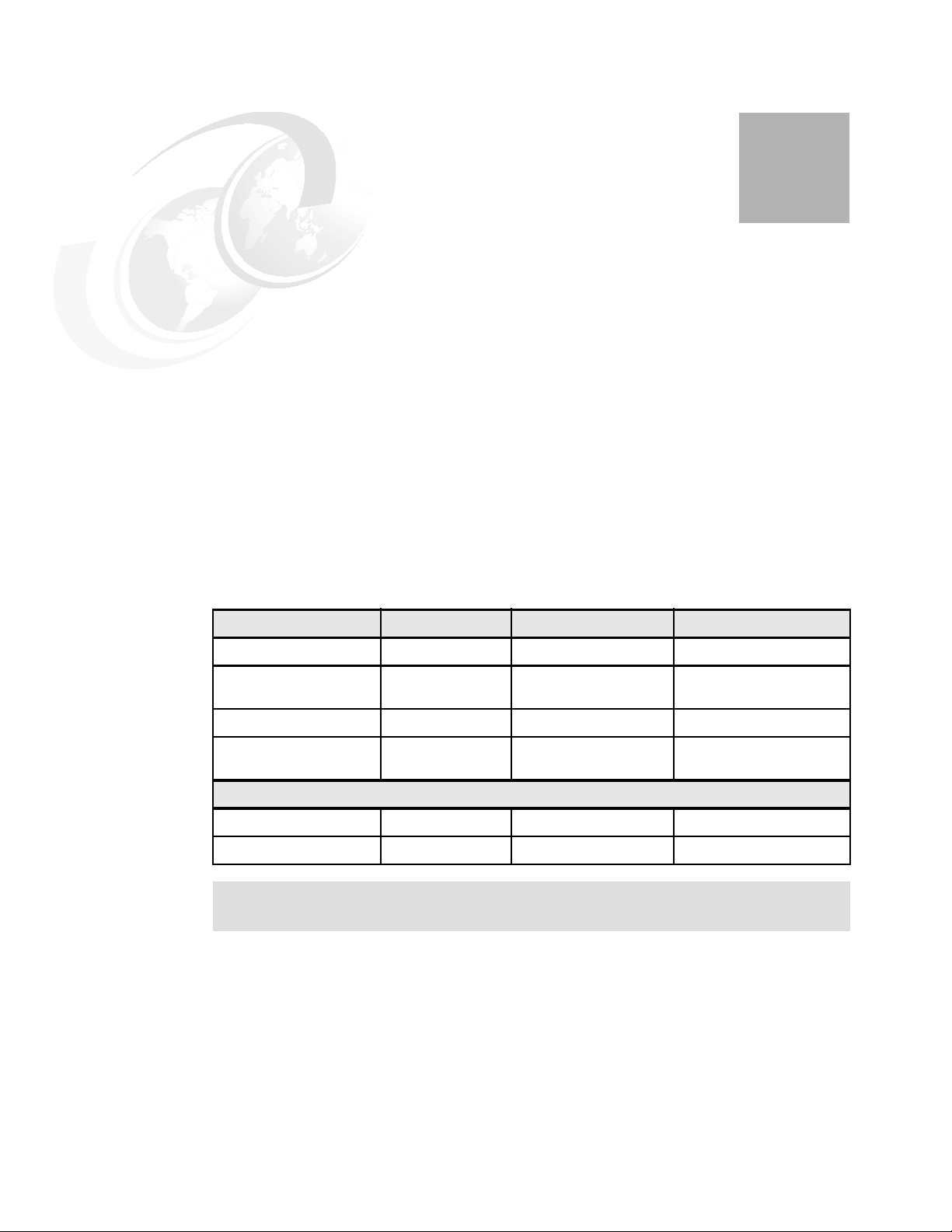
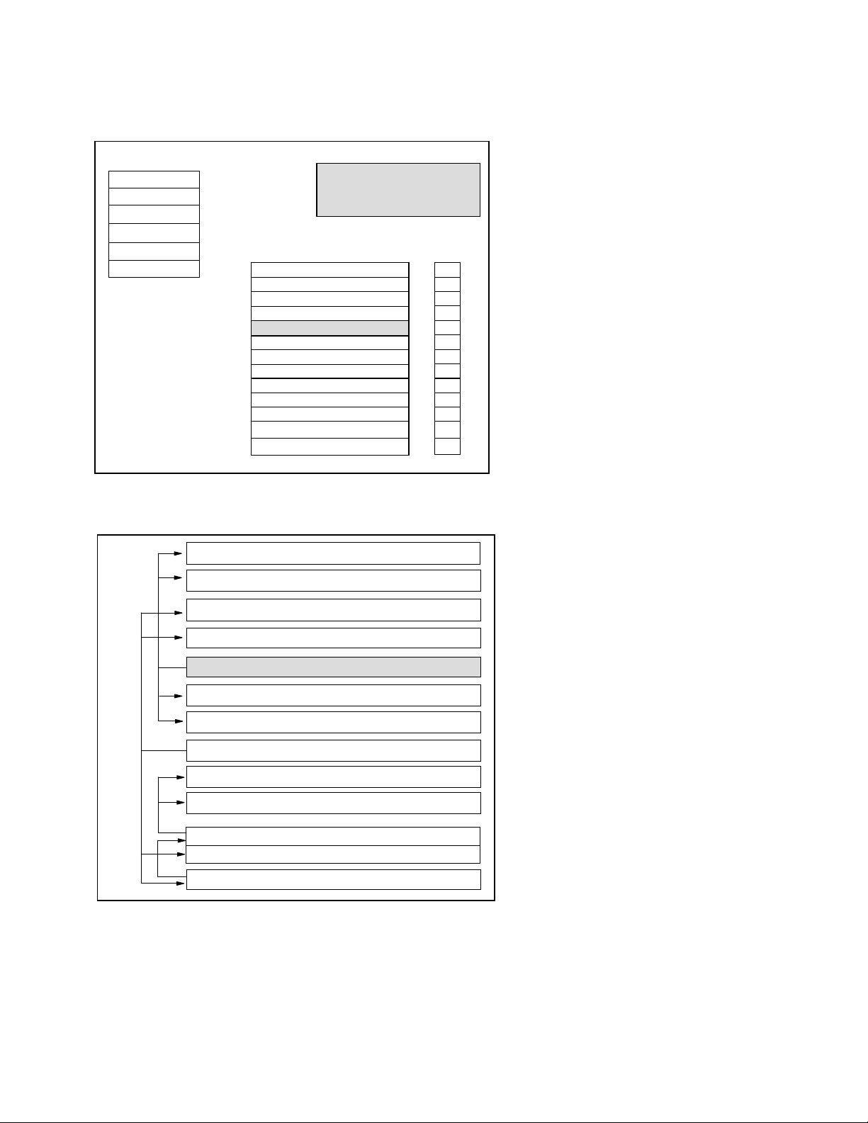
Model and processor Announce date General availability date Withdrawn from marketing
1
170 #2159 10 February 1998 27 February 1998 31 May 1999
170 #2160, #2164, #2176,
#2183
170 #2289 09 February 1999 27 February 1998 31 May 2001
170 #2290, #2291, #2292,
#2385, #2386, #2388
Dedicated Server for Domino®
#2407 03 August 1999 27 February 1998 31 May 2001
#2408 and #2409 03 August 1999 27 February 1998 28 December 2001
Note: The darker shaded areas in the following tables and graphics indicate the base
features.
10 February 1998 27 February 1998 28 December 2001
01 September 1998 27 February 1998 28 December 2001
© Copyright IBM Corp. 1997 1998 1999 2000 2001 2002 2003 2004 2005 2006 2007. All rights reserved. 1
Page 18

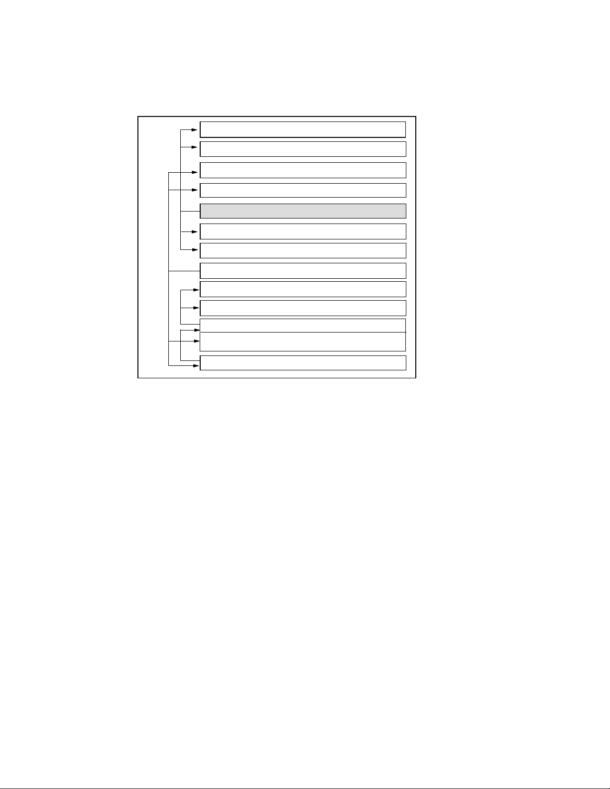
1.1 AS/400e Model 170 overview
The following tables provide the minimum and maximum capacities for the Model 170.
Model 170 (February 1998)
Processor feature
(CPW)
1
2
Relative system performance (CPW)
Client/server environment 75.0 114.0 210.0 319.0 319.0
Interactive environment 16.0 23.0 29.0 39.0 65.0
Number/type/speed of processor 1/Apache
Main storage (MB min to max) 64 to 832 64 to 832 256 to 1024 256 to 1024 256 to 1024
Minimum OS/400® level V4R3 V4R3 V4R3 V4R3 V4R3
Processor feature
Relative system performance
Processor performance 50 73 115 220 460 460 1090
Interactive performance 15 20 25 30 50 70 70
Number/type/speed of processor 1/Northstar
Main storage (MB min to max) 64 to 832 64 to 832 64 to 832 256 to 256 to 256 to 256 to
Minimum OS/400 level V4R3 V4R3 V4R3 V4R3 V4R3 V4R3 V4R3
#2159 #2160 #2164 #2176 #2183
1/Apache
/125 MHz
#2289 #2290 #2291 #2292 #2385 #2386 #2388
1/Northstar
/262 MHz
/262 MHz
/125 MHz
Model 170 (September 1998/February 1999)
1/Northstar
/262 MHz
1/Apache
/125 MHz
1/Northstar
/262 MHz
1/Northstar
/262 MHz
1/Apache
/125 MHz
1/Northstar
/262 MHz
1/Apache
/125 MHz
2/Northstar
/262 MHz
2 iSeries and AS/400e System Builder
Page 19
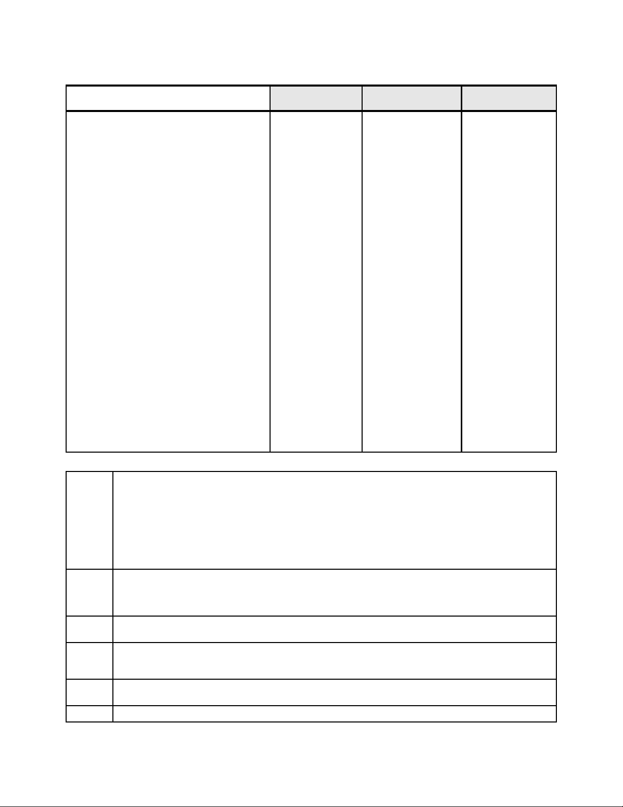
Base system for all
processors
5
#7102 System
Expansion Unit
5
Total maximum5
Disk storage (GB)
Minimum internal 4.19 0 4.19
Maximum internal (V4R2) 34.32 51.48 85.80
Maximum internal (V4R3 and later) 70.16 105.24 175.40
System I/O card slots
Low-speed PCI 2 4 6
Low-speed IPCS PCI 2 2 4
High-speed DASD IOA PCI 1 0 1
High-speed tape IOA PCI 0 1 1
High-speed Ethernet or ATM
Maximum communication lines
ATM adapters
6
Maximum LAN/ATM adapters
3
1 2 3
4
6
1-12 0-18 30
0-1 0-2 3
3 4 7
Non-Integrated Server LAN Low-Speed TR/Ethernet 1 4 5
Non-Integrated Server LAN 100/10 Ethernet 1 2 3
Integrated Server LAN Low-Speed TR/Ethernet 2 2 4
Integrated Server LAN 100/10 Ethernet 1 1 2
Maximum workstation controllers
Twinaxial (only) 3 5 6
Maximum workstations
Twinaxial (only) 28/108 200 228
Cryptographic processors 0 2 2
Cryptographic accelerator
¼-inch cartridge tape (internal) 0-1 0 1
½-inch tape (external)
Reel 9348 0 0-2 2
Reel 2440, 9347 0 0 0
Cartridge 34xx, 35xx 0 0-2 2
8 mm ½-inch cartridge (external) 0 0-2 2
CD-ROM 1 0 1
Optical libraries 0 0-2 2
Note 1 Commercial Processing Workload (CPW) is used to measure the performance of all iSeries and AS/400e processors
announced from September 1996 onward. The CPW value is measured on maximum configurations. The type and number
of disk devices, the number of workstation controllers, the amount of memory, the system model, other factors, and the
application being run determine what performance is achievable. With the introduction of the Dedicated Servers for Domino,
Simple Mail Users has been added as a performance measurement.
The constrained figures are for the 9406 Model 170 with its maximum configuration. The unconstrained figures show what
the performance would be if the processor was not limited by the maximum main storage and direct access storage device
(DASD) of the Model 170.
Note 2 Processor performance represents the relative performance (maximum capacity) of a processor feature running CPW in a
client/server environment. Processor capacity is achievable when the commercial workload is not constrained by main
storage and DASD. Interactive performance represents the relative performance available to perform host-centric
workloads. The amount of interactive capacity consumed reduces the available processor capacity by the same amount.
Note 3 The Integrated Server is mutually exclusive with the high-speed slot C03 for LAN, ATM or communications in the base
system unit.
Note 4 One line is used by the Operations Console or Client Access Console if selected. The total is reduced by one if a Twinaxial
Console is selected. To reach the maximum of 18 communication lines using the #2745/#9745 in slot C03, remove the base
LAN adapter.
Note 5 Base system totals are the maximum for the #2289 processor. The #2289 processor does not support attachment of the
#7101 or #7102 System Expansion Unit.
Note 6 Integrated Server can refer to either Integrated PC Server (IPCS) or #2790 PCI Integrated Netfinity Server.
Chapter 1. IBM AS/400e 170 models 3
Page 20
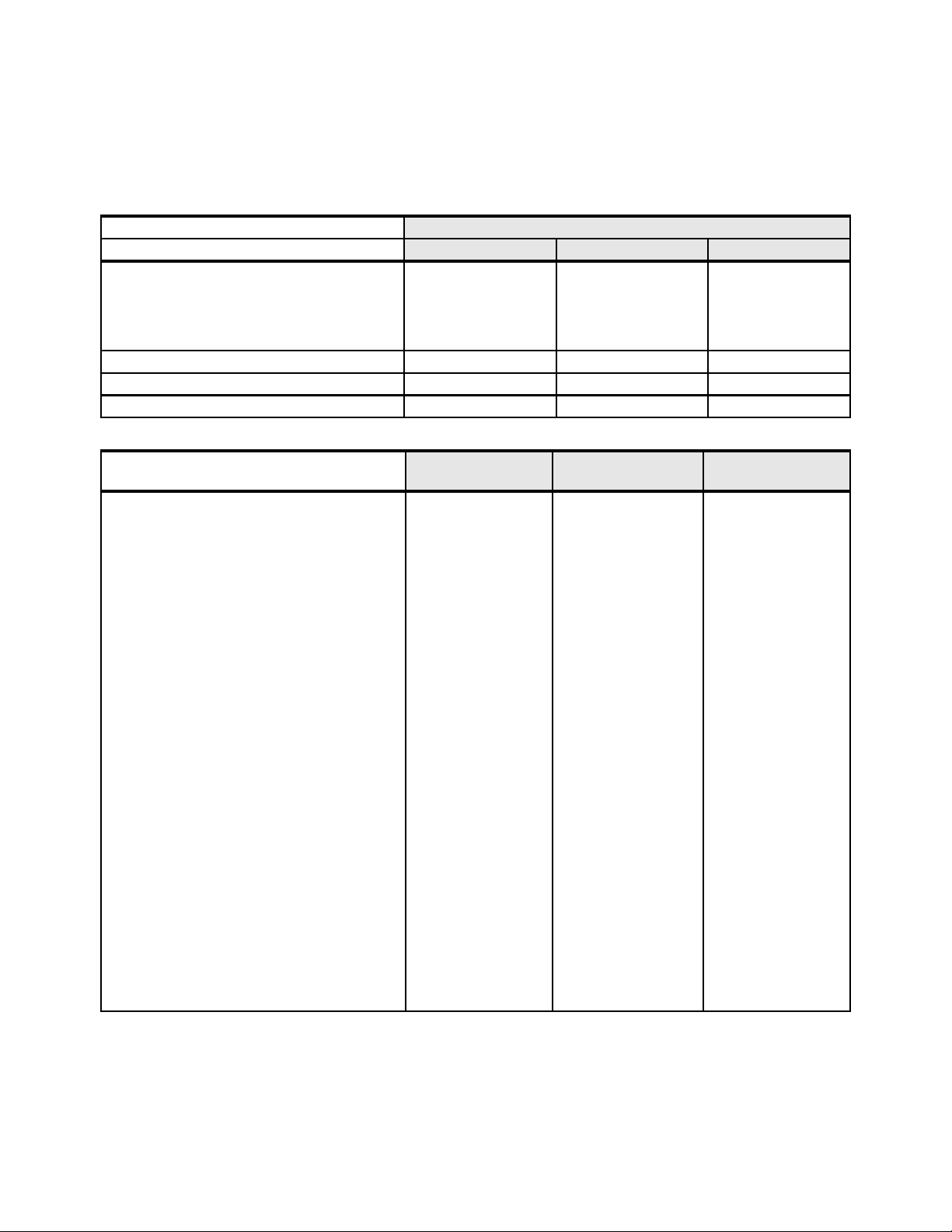
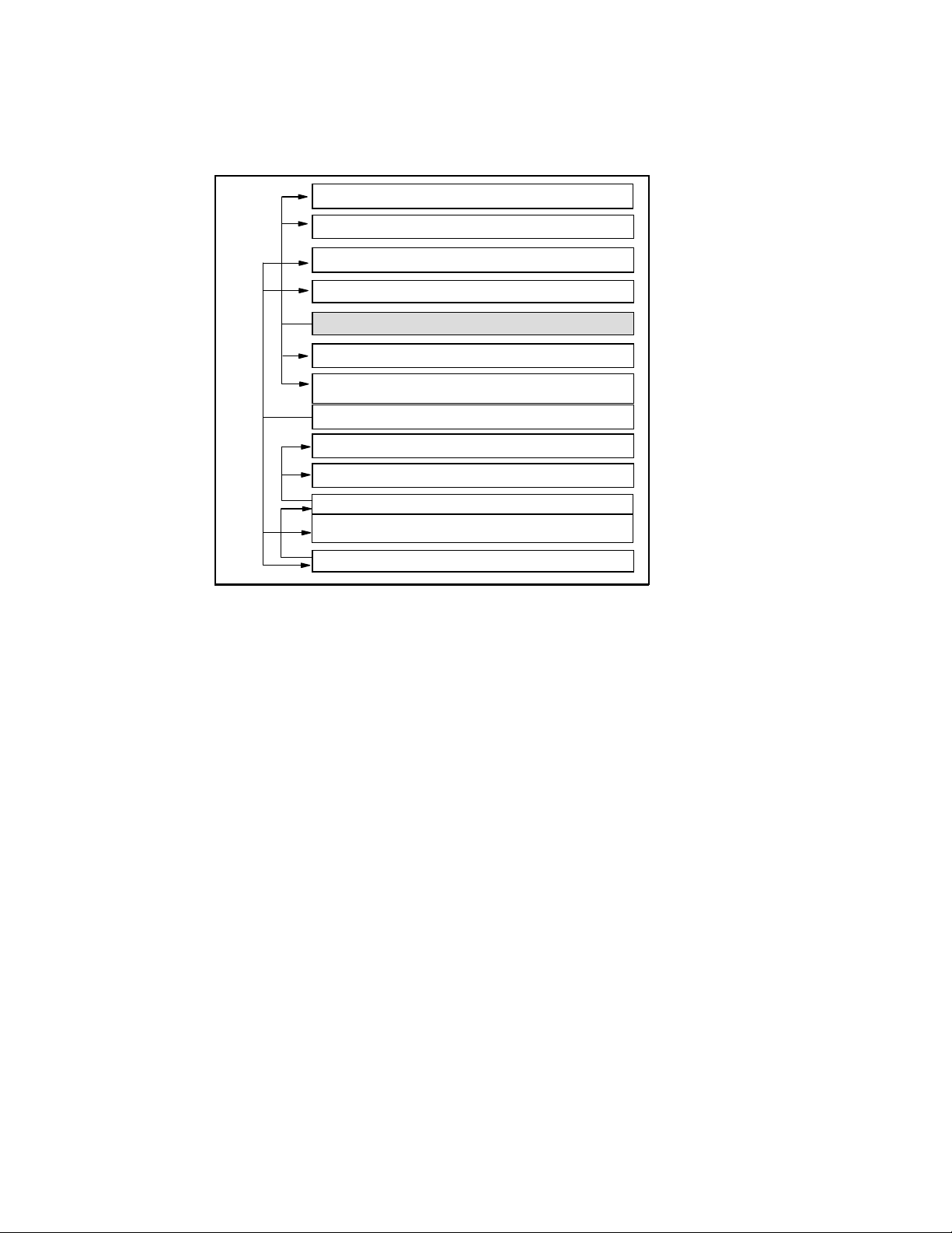
1.2 AS/400e Dedicated Server for Domino overview
The following table provides the Model 170 Dedicated Server for Domino minimum and
maximum capacities.
Model Dedicated Server for Domino (August 1999)
Processor feature
Relative system performance (CPW)
Client/server environment 30 60 120
Interactive environment 10 15 20
Simple Mail Users 1300 2300 4300
Number/type/speed of processor 1/Northstar/262 MHz 1/Northstar/262 MHz 2/Northstar/262 MHz
Main storage (MB min to max) 256 to 1024 512 to 4096 512 to 4096
Minimum OS/400 level V4R4 V4R4 V4R4
1
#2407 #2408 #2409
Base system for all
processors
Disk storage (GB)
Minimum internal 4.19 0 4.19
Maximum internal (V4R2) 34.32 51.48 85.80
Maximum internal (V4R3 and later) 70.16 105.24 175.40
System I/O card slots
Low-speed PCI 2 4 6
Low-speed IPCS PCI 2 2 4
High-speed DASD IOA PCI 1 0 1
High-speed tape IOA PCI 0 1 1
High-speed Ethernet or ATM
Maximum communication lines
ATM adapters
Maximum LAN/ATM adapters
Non-Integrated Server LAN Low-Speed 1 5 5
Non-Integrated Server LAN 100/10 Ethernet 1 2 3
Integrated Server LAN Low-Speed TR/Ethernet 2 2 4
Integrated Server LAN 100/10 Ethernet 1 1 2
Maximum workstation controllers
Twinaxial (only) 3 5 6
Maximum workstations
Twinaxial (only) 28/108 200 228
Cryptographic processors 0 2 2
Cryptographic accelerator
¼-inch cartridge tape (internal) 0-1 0 1
½-inch tape (external)
Reel 9348 0 0-2 2
Reel 2440, 9347 0 0 0
Cartridge 34xx, 35xx 0 0-2 2
8 mm ½-inch cartridge (external) 0 0-2 2
CD-ROM 1 0 1
Optical libraries 0 0-2 2
6
3
4
6
1 2 3
1-12 0-18 30
0-1 0-2 3
3 4 7
5
#7102 System
Expansion Unit
5
Total maximum
5
4 iSeries and AS/400e System Builder
Page 21
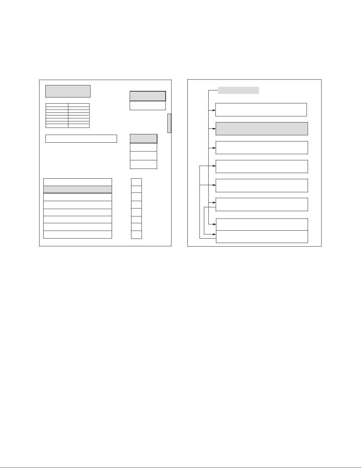
1.3 9406 Model 170 system and expansion unit schematics
9406 Model 170 System Unit
9406 Model 170 System Unit
340 or 350 Watt Power
Supply (Note 8)
**
PROCESSOR
Base Memory Base Memory
Memory Riser Card M02
M02 Riser Cards is only for processors
*
#2385, #2386, #2388, #2408 & #2409.
Memory DIMMs plug directly to the planar
**
on processors #2289, #2290, #2291 & # 2292
PCI Cards
PCI Card
ECS & Console #9720/#9721/#9745
Disk Cont. #2740/#2741/#9728/#2748
Integrated Server LAN Slot
Integrated Server LAN Slot
Integrated Server Bridge Card
(reserved) )
High Speed Slot
Integrated Server Proc. Card
#2857/#2866 (Note 10)
MFIOP
*
D02
D01
CD-ROM
Magnetic Media
Disk Unit
Disk Unit
Disk Unit
Disk Unit
Slots
C09
C08
C07
C06
C05
C04
C03
C02
OP Panel
L01
L02
L03
L04
PCI Card Placement
Slot
MFIOP
C09
C08
C07
C06
C05
C04
C03
C02
LAN/WAN/Twinax IOA
WAN/Twinax IOA #9720 or
2-Line WAN IOA #9721/#9745
Disk Controller #9728/#2740/#2741/#2748
Integrated Server LAN Slot
Integrated Server High Speed LAN slot
Integrated Server Bridge Slot (reserved)
LAN/WAN/ATM slot (Notes 2, 3, 5,6 & 9)
Integrated Server Proc Slot #2857 / #2866
Notes:
1. No high-speed LAN is allowed in slot C09.
2. If any card is in slot C03, then no LAN card is allowed in slot C09.
3. Communications cards #2750, #2751, and #2761 are only allowed in high-speed slot C03.
4. The #2289, #2290, #2291, and #2292 processors include embedded #9728 Base Disk
Unit Controller. A separate #9728 is not needed.
5. If any IPCS is in slots C02/C04, C03 must remain empty.
6. In C03, the #2811, #2812, #2819, #2745, #2750, #2751, #2761, #2746, #2723, #2724,
and #2838 are supported.
7. Integrated Server can refer to either Integrated PC Server or Integrated Netfinity® Server.
8. The 340W is in the #2289, #2290, #2291, and #2292, and the 350W is in the #2385 and
#2386.
9. ATM is not supported after OS/400 V5R2. Upgrade to Ethernet.
10.The #2857 is not supported because Windows® NT is no longer supported. Upgrade to
#2866. Upgrade Windows NT® to Windows 2000.
Chapter 1. IBM AS/400e 170 models 5
Page 22

Model 170 Main Storage Riser Card (M02)
for Processors #2385, #2386, #2388, #2408, #2409
4b
3b
2b
1b
4a
3a
2a
Base Memory 1a
4b
3b
2b
1b
4a
3a
2a
Base Memory 1a
Notes:
1. DIMMS should be plugged in pairs in a sequential order, without leaving a gap.
2. Base memory cannot be upgraded.
3. When the upper half of the riser card is used (slot b), all DIMMS in those slots must match
the corresponding bottom (a) slots (that is, quad).
6 iSeries and AS/400e System Builder
Page 23
9406 Model 170 #7101/#7102 System Expansion Unit
Disk Unit
Disk Unit
Disk Unit
Disk Unit
Disk Unit
Disk Unit
F11
F12
F13
F14
F15
F16
* Note 7
350 Watt Power Supply
PCI Cards
Low Speed PCI Slot
Low Speed PCI Slot
Low Speed PCI Slot
Low Speed PCI Slot
Base Controller
Tape Controller #2729/#2718
LAN/ATM Adapter (Note 6)
Feat. Controller #2809/#2824
Integrated Server LAN Slot
Integrated Server LAN Slot
Int. Server Proc #2857/#2866 *
High Speed PCI Slot
Int. Server Bridge Card
PCI Card Cage for the #7101 System Expansion Unit
Base #2809/CCIN 2809
Slot
E14
E13
2-Line WAN IOA #2721/#2745 or Twinaxial IOA #2722 / #2746
2-Line WAN IOA #2721/#2745 or Twinaxial IOA #2722 / #2746
E14
E13
E12
E11
E10
E09
E08
E07
E06
E05
E04
E03
E02
Notes:
1. If any ATM is in slot E08, slot E13 must
remain empty. Base memory cannot
be upgraded.
2. If an Integrated Server is in slots
E02/E04, E03 must remain empty.
3. Both high-speed and low-speed ATMs
are supported in the system expansion
unit.
4. The disk units in the expansion unit are
covered by the #2740, #2741, #2748,
or #9740 PCI RAID Disk Unit Controller
in the system unit.
5. Integrated Server can refer to
Integrated PC Server or Integrated
Netfinity Server.
6. The #281x ATM is not supported after
OS/400 V5R2. Upgrade to Ethernet.
7. The #2857 is not supported because
Windows NT is no longer supported.
Upgrade to #2866. Upgrade Windows
NT to Windows 2000.
E12
E11
E10
E09
E08
E07
E06
E05
E04
E03
E02
2-Line WAN IOA #2721/#2745 or Twinaxial IOA #2722 / #2746
2-Line WAN IOA #2721/#2745 or Twinaxial IOA #2722 / #2746
Base Controller (CCIN 2809)
Tape Controller #2729/#2718
#2723/#2724/#2745/#281x/#2838 (Note 6)
Feature Controller Slot #2809
Integrated Server LAN IOA #2723 / #2724
Integrated Server LAN IOA #2723 / #2724 / #2838
Integrated Server Processor Card Slot #2857 / #2866 (Note 7)
#2718/#2729#2723/#2724/#2745/#281x/#2838 (Note 6)
Integrated Server Bridge Card Slot (reserved position)
Chapter 1. IBM AS/400e 170 models 7
Page 24
PCI Card Cage For #7101 System Expansion Unit
#2824/Base CCIN 2824
Slot
E14
E13
E12
E11
E10
E09
E08
E07
E06
E05
E04
E03
E02
2-Line WAN IOA #2721/#2745 or Twinaxial IOA #2722 / #2746
2-Line WAN IOA #2721/#2745 or Twinaxial IOA #2722 / #2746
#2721 / #2722 / #2723 / #2724 / #2745 / #2746
#2721 / #2722 / #2723 / #2724 / #2745 / #2746
Base Controller (CCIN 2809)
Tape Controller #2729/#2718
High Speed LAN / ATM Adapter (Note 8)
Feature Controller Slot #2824
Integrated Server LAN IOA #2723 / #2724
Integrated Server LAN IOA #2723 / #2724 / #2838
Integrated Server Processor Card Slot #2857 / #2866 (Note 9)
#2723/#2724/#2718/#2729/#2745/#2746/#2750/#2751/#2761
#281x/#2838/#4800 (Note 8 )
Integrated Server Bridge Card Slot (reserved position)
Notes:
1. If any ATM is in slot E08, slot E13 must remain empty. Base memory cannot be upgraded.
2. If an Integrated Server is in slot E02/E04, slot E03 must remain empty.
3. Both high-speed and low-speed ATMs are supported in the system expansion unit.
4. The disk units in the expansion unit are covered by the #2740, #9740, #2741, or #2748
PCI RAID Disk Unit Controller in the system unit.
5. Communications cards #2750, #2751, and #2761 are allowed in slot E03.
6. The #4800 PCI Cryptographic Processor is only allowed in high-speed slot E03.
7. Integrated Server can refer to Integrated PC Server or Integrated Netfinity Server.
8. The #2750 PCI ISDN BRI U Adapter, #2751 PCI ISDN BRI S/T IOA (Integrated Services
Digital Network (ISDN)), and #2761 Integrated Analog Modem are not supported. The
#281x ATM is not supported after V5R2. Upgrade to Ethernet.
9. The #2857 Integrated PC Server not supported because Windows NT is no longer
supported. Upgrade to #2866 PCI Integrated Netfinity Server. Upgrade Windows NT to
Windows 2000.
8 iSeries and AS/400e System Builder
Page 25
PCI Card Cage for the #7102 System Expansion Unit
#2824/Base CCIN 2824
Slot
E14
E13
E12
E11
E10
E09
E08
E07
E06
E05
E04
E03
E02
#2721/#2722/#2723/#2724/#2745/#2746
#2721/#2722/#2723/#2724/#2745/#2746
#2721/#2722/#2723/#2724/#2745/#2746
#2721/#2722/#2723/#2724/#2745/#2746
Base Controller (CCIN 2824)
#2729/#2718/#2745/#2746/#2750/#2751/#2761/#4800 (Note 9)
#2723/#2724/#2745/#2746/#2750/#2751/#2761/#281x/#2838/#4800
(Note 9)
Feature Controller Slot #2824
Integrated Server LAN IOA #2723 / #2724
Integrated server LAN IOA #2723 / #2724 / #2838
Integrated Server Processor Card Slot #2857 / #2866 (Note 10)
#2718/#2729#2723/#2724/#2745/#2746/#2750/#2751/#2761
#2838/#281x/#4800 (Note 9)
Integrated Server Bridge Card Slot (reserved position)
Notes:
1. If any ATM is in slot E08, slot E13 must remain empty. Base memory cannot be upgraded.
2. If either 100/10 Ethernet or any ATM card is in slot E03 or E08, no other LAN is allowed in
slots E11/E12 or E13/E14.
3. If an Integrated Server is in slots E02 or E04, slot E03 must remain empty.
4. Both high-speed and low-speed ATMs are supported in the system expansion unit.
5. The disk units in the expansion unit are covered by the #2740, #9740, #2741, or #2748
PCI RAID Disk Unit Controller in the system unit.
6. Communications cards #2750, #2751, and #2761 are allowed in slots E03, E08, and E09
(maximum one per input/output processor (IOP)).
7. The #4800 PCI Cryptographic Processor is allowed in high-speed slots E03, E08, or E09
(maximum one per IOP).
8. Integrated Server can refer to Integrated PC Server or Integrated Netfinity Server.
9. The #281x ATM is not supported after OS/400 V5R2. Upgrade to Ethernet. The #2750
PCI ISDN BRI U Adapter, #2751 PCI ISDN BRI S/T IOA (ISDN), and #2761 Integrated
Analog Modem are not supported.
10.The #2857 Integrated PC Server is not supported because Windows NT is no longer
supported. Upgrade to #2866 PCI Integrated Netfinity Server. Upgrade Windows NT to
Windows 2000.
Chapter 1. IBM AS/400e 170 models 9
Page 26

1.4 AS/400e Model 170 processors
The AS/400e Model 170 systems are Customer Setup (CSU).
170 Processors
#2159 75.0 RSP CPW Processor in Client/Server Environment (Unconstrained), 16.0 RSP CPW Processor in Interactive
#2160 114.0 RSP CPW Processor in Client/Server Environment (Unconstrained), 23.0 RSP CPW Processor in
#2164 210.0 RSP CPW Processor in Client/Server Environment (Unconstrained), 29.0 RSP CPW Processor in
#2176 319.0 RSP CPW Processor in Client/Server Environment (Unconstrained), 39.0 RSP CPW Processor in
#2183 319.0 RSP CPW Processor in Client/Server Environment (Unconstrained), 65.0 RSP CPW Processor in
#2289 50 RSP CPW Processor in Client/Server Environment (Unconstrained), 15 RSP CPW Processor in Interactive
#2290 73 RSP CPW Processor in Client/Server Environment (Unconstrained), 20 RSP CPW Processor in Interactive
#2291 115 RSP CPW Processor in Client/Server Environment (Unconstrained), 25 RSP CPW Processor in Interactive
#2292 220 RSP CPW Processor in Client/Server Environment (Unconstrained), 30 RSP CPW Processor in Interactive
#2385 460 RSP CPW Processor in Client/Server Environment (Unconstrained), 50 RSP CPW Processor in Interactive
#2386 460 RSP CPW Processor in Client/Server Environment (Unconstrained), 70 RSP CPW Processor in Interactive
#2388 1090 RSP CPW 2-way Processor in Client/Server Environment (Unconstrained), 70 RSP CPW Processor in
#2407 Dedicated Domino Processor, 1300 Simple Mail Users, 30 RSP CPW Processor in Client/Server Environment,
#2408 Dedicated Domino Processor, 2300 Simple Mail Users, 60 RSP CPW Processor in Client/Server Environment,
#2409 Dedicated Domino Processor, 4300 Simple Mail Users, 120 RSP CPW Processor in Client/Server Environment,
Environment (Constrained and Unconstrained). Base Memory 64 MB.
Interactive Environment (Constrained and Unconstrained). Base Memory 64 MB.
Interactive Environment (Constrained and Unconstrained). Base Memory 256 MB.
Interactive Environment (Unconstrained). Base Memory 256 MB.
Interactive Environment (Unconstrained). Base Memory 256 MB.
Environment (Unconstrained). Base Memory 64 MB.
Environment (Unconstrained). Base Memory 64 MB.
Environment (Unconstrained). Base Memory 64 MB.
Environment (Unconstrained). Base Memory 256 MB.
Environment (Unconstrained). Base Memory 256 MB.
Environment (Unconstrained). Base Memory 256 MB.
Interactive Environment (Unconstrained). Base Memory 256 MB.
10 RSP CPW in Interactive Environment. Base Memory 256 MB.
15 RSP CPW in Interactive Environment. Base Memory 512 MB.
20 RSP CPW in Interactive Environment. Base Memory 512 MB.
10 iSeries and AS/400e System Builder
Page 27

1.5 AS/400e Model 170 features
This section identifies the supported features for the AS/400e Model 170.
PCI cards are subject to plugging rules. See PCI Card Placement Rules for the IBM eServer
iSeries Server, REDP-3638 for details.
Power and packaging
#1402 Line cord 9-ft 120 volt
Feature #1402 specifies 9 ft (2.8 m), 15 Amp, and 120 volt (U.S. default). The #1402 specify feature provides up to two
line cords: one for the system and one for the expansion unit. One line cord is provided for the system unit.
#1403 Line cord 9-ft 240 volt
Feature #1402 specifies 9 ft (2.8 m), 15 Amp, and 240 volt. This specify provides up to two line cords: one for the system
and one for the expansion unit. One line cord is provided for the system unit.
#7101 #7101 System Expansion Unit
The #7101 System Expansion Unit allows the addition of up to nine Peripheral Component Interconnect (PCI) cards. It
includes a base controller (CCIN 2809) as standard and can have another added by installing a #2809. The #7101 can
also support one #2857 Integrated PC Server or one #2866 PCI Integrated Netfinity Server. The #7101 supports up to
six disks (driven by the same disk controller located in the system unit).
The #7101 is mutually exclusive with a #7102 System Expansion Unit.
Maximum: One per system; requires one #1402 or #1403 line cord
Not available on the #2289, #2407, #2408, or #2409 processors
#7102 #7102 System Expansion Unit
The #7102 System Expansion Unit allows the addition of up to nine PCI cards. It includes a base controller (CCIN 2824)
with 32 MB of memory as standard and can have another added by installing a #2824 PCI Feature Controller. The #7102
can also support one #2857 Integrated PC Server or one #2866 PCI Integrated Netfinity Server. The #7102 additionally
supports up to six disks (driven by the same disk controller located in the system unit).
The #7102 is mutually exclusive with a #7101 System Expansion Unit.
Maximum: One per system; requires one #1402 or #1403 line cord
Minimum operating system level: OS/400 V4R4
Not available on the #2289 processor
Main storage
Base There are no features to specify the base memory of 64 MB on the Model 170 #2159, #2160, #2289, #2290, and #2291
#3001 32 MB Main Storage (DIMM)
processors. There are also no features to specify for 256 MB on the Model 170 #2164, #2176, #2183, #2292, #2385,
#2386, and #2388 processors, for 256 MB on the #2407 Dedicated Domino Processor, or for 512 MB on the #2408 and
#2409 Dedicated Domino Processors.
The #3001 plugs directly into the CPU or memory riser card depending on the processor feature. Must be added in pairs.
Maximum: Six on all processors, except the #2385, #2386 and #2388 processors, which support a maximum of 12, and
#2408, #2409, which support a maximum of 12.
The #3001 is a Customer Install Feature (CIF) for an Miscellaneous Equipment Specification (MES) that only includes
CIF features.
#3002 128 MB Main Storage (DIMM)
The #3002 plugs directly into the CPU or memory riser card depending on the processor feature. Must be added in pairs.
Maximum: Six on all processors except the #2385, #2386, and #2388, which support a maximum of 14 and Dedicated
Domino processors #2408 and #2409, which support a maximum of 12.
The #3002 is a Customer Install Feature for an MES that only includes CIF features.
#3003 256 MB Main Storage (DIMM)
The #3003 plugs directly into the CPU or memory riser card depending on the processor feature. Must be added in pairs.
Mixing #3003 and #3004 within pairs (or quads on the #2385, #2386, and #2388 processors when more than eight
memory features are installed) is not allowed.
Maximum: 12.
Minimum operating system level: OS/400 V4R3
Supported on processors #2385, #2386, and #2388 only
The #3003 is a Customer Install Feature for an MES that only includes CIF features.
Chapter 1. IBM AS/400e 170 models 11
Page 28

#3004 256 MB Main Storage (DIMM)
The #3004 plugs directly into the CPU board or memory riser card depending on the processor feature. Must be added
in pairs.
Mixing of #3003 and #3004 within pairs (or quads on the #2385, #2386 and #2388 processors when more than eight
memory features are installed) is
Maximum: Two on the #2289, #2290, #2291, #2292, and #2407 processors; 12 on the #2385, #2386, and #2388
processors; 14 on the #2408 and #2409 processors
The #3004 is a Customer Install Feature for an MES that only includes CIF features.
Base
MFIOP
Base
MFIOP
Base Multifunction IOP (for processors #2159, #2160, #2164, #2176, #2183, #2385, #2386, #2388, #2408, and
#2409)
The base system includes this MFIOP (CCIN 6757), which plugs on the processor card, and supports two high-speed
PCI card slots C07, C03 and two low-speed PCI card slots C08, C09. The #2408 and #2409 processors include a #9740
Base RAID Disk Unit Controller in slot C07.
Slot C07 has a #9728 Base Disk Unit Controller, a #9740 Base RAID Disk Unit Controller, a #2740, #2741, or #2748 PCI
RAID Disk Unit Controller.
Slots C02/C04 are reserved for one #2857 Integrated PC Server or #2866 PCI Integrated Netfinity Server, and can only
be used if there is no card in C03.
Slot C03 supports one #2723/#9723/#2724/#9724/#2838/#9738 PCI LAN input/ output adapter (IOA), or low-speed
#2811/#2812/#2819 ATM, or #2745/#2750/#2751/#2761 PCI WAN IOA, or #2746 PCI Twinaxial Workstation IOA.
C08 is reserved for one base #9720/#9721 or #9745 Base PCI 2-Line WAN IOA.
C09 is limited to #2721/#2722/#2745/#2746 PCI IOAs if any card is in C03. If C03 is empty, it also supports one
#2723/#9723/#2724/#9724 PCI LAN IOA, or #9720 Base PCI WAN/Twinaxial IOA, or #2746 PCI Twinaxial Workstation
IOA.
Base Multifunction IOP (for #2289, #2290, #2291, #2292, and #2407)
The MFIOP (CCIN 675A) and the processor are combined together on the planar board. It also includes embedded base
disk unit controller. A separate #9728 is not required. The #2407 includes a #9740 Base RAID Disk Unit Controller. The
MFIOP drives two low-speed slots C08, C09, and two high-speed PCI slots C03 and C07. It supports #2740/#9740,
#2741 or #2748 PCI RAID Disk Unit Controllers only, if there are more than four disk drives, and RAID-5 is required.
not allowed.
Workstation controllers
Slots C02/C04 are reserved for one #2857 Integrated PC Server or #2866 PCI Integrated Netfinity Server, and can only
be used if there is no card in slot C03.
Slot C03 supports one #2723/#9723/#2724/#9724/#2838/#9738 PCI LAN IOAs, or low-speed #2811/#2812/#2819
ATMs, or #2745, #2750, #2751 and #2761 PCI WAN IOAs or #2746 PCI Twinaxial Workstation IOA.
Slot C08 is reserved for one #9720/#9721 or #9745 Base PCI 2-Line WAN IOA.
Slot C09 is limited to #2721/#2722/#2745/#2746 PCI IOAs if any card is in C03. If C03 is empty, it also supports one
#2723/#9723/#2724/#9724 PCI LAN IOA or #9720 Base PCI WAN/Twinaxial IOA or #2746 PCI Twinaxial Workstation
IOA.
The #2745 can be in either a low-speed or a high-speed slot.
Base IOP Base Controller for #7101 System Expansion Unit
One LAN/WAN/Workstation IOP (CCIN 2809) is supplied as standard within the #7101 and is installed in slot E10. It
provides support for two high-speed PCI card slots E08 and E09, and two low-speed PCI card slots E13 and E14.
Slot E08 supports one of the following LAN cards: #2838, #2723, #2724 or #281x ATM cards, or #2745 PCI 2-Line
WAN IOA.
Slot E09 supports the #2718 or #2729 PCI Magnetic Media Controller.
The low-speed slots E13 and E14 support cards #2721/#2745 PCI 2-Line WAN IOA and #2722/#2746 PCI
Twinaxial Workstation IOA. If any ATM card is in E08, then slot E13 must be empty.
12 iSeries and AS/400e System Builder
Page 29

Base IOP Base Controller for #7102 System Expansion Unit
One LAN/WAN/Workstation IOP (CCIN 2824) is supplied as standard within the #7102, and is installed in slot E10. It
provides support for two high-speed PCI card slots E08 and E09, and two low-speed PCI card slots E13 and E14.
Slot E08 supports one of the following LAN cards: The #2838, #2723, #2724, or #281x ATM cards or the #2745 PCI
2-Line WAN IOA or the #2746 PCI Twinaxial Workstation IOA or the #2750/#2751 PCI ISDN BRI S/T IOA, the
#2761 Integrated Analog Modem, or the #4800 PCI Cryptographic Processor.
Slot E09 supports the #2718/#2729 PCI Magnetic Media Controller the #2745 PCI 2-Line WAN IOA, the #2746 PCI
Twinaxial Workstation IOA, the #2750/#2751 PCI ISDN BRI S/T IOA, the #2761 Integrated Analog Modem, or the
#4800 PCI Cryptographic Processor.
The low-speed slots E13 and E14 support cards #2721, #2722, #2723, #2724, #2745, or #2746. If any ATM card is
in E08, E13 must be empty.
#2720
#9720
#2722 #2722 Twinaxial Workstation IOA
#2746 #2746 PCI Twinaxial Workstation IOA
#2720 Base PCI WAN/Twinaxial IOA
The #2720 is a combined twinaxial/communications adapter. It can be included as base in the Model 170. The #2720
provides four ports supporting a maximum of 28 twinaxial devices. It also provides a single communications line to
support ECS. See “#2720” on page 14.
PCI slots required: One
Maximum: One
One eight-port attachment is provided to support 40 twinaxial devices.
PCI slots required: One
Maximum: Five
The #2722 is a Customer Install Feature for an MES that only includes CIF features.
One eight-port attachment is provided to support 40 twinaxial devices. The #2746 can be attached both to high- and
low-speed slots.
PCI slots required: One
Maximum: Five
Minimum operating system level: OS/400 V4R4
The #2746 is a Customer Install Feature for an MES that only includes CIF features.
#2809 #2809 PCI LAN/WAN/Workstation IOP
The #2809 provides support for two low-speed PCI card slots E11 and E12, also one high-speed PCI card slot E03. It is
a feature controller for LAN/WAN/Workstation in the #7101 System Expansion Unit. It can be installed in E07 in the
#7101 System Expansion Unit only. One #2809 PCI LAN/WAN/Workstation IOP is supplied as standard within the #7101
with no feature required. See “Base IOP” on page 12.
Slot E03 can only be used if no #2857 Integrated PC Server or #2866 PCI Integrated Netfinity Server card is
installed in slots E02/E04.
Slot E03 supports one #2718, #2729, #2723, #2724, #2745, #2838, or #281x.
Slots E11 and E12 support #2721/#2745 PCI 2-Line WAN IOA and #2722/#2746 PCI Twinaxial Workstation IOA.
Maximum: One in #7101 System Expansion Unit
The #2809 does not attach to the #7102 System Expansion Unit.
The #2809 is a Customer Install Feature for an MES that only includes CIF features.
The #2809 was withdrawn from marketing on 31 May 2001.
Chapter 1. IBM AS/400e 170 models 13
Page 30

#2824 #2824 PCI Feature Controller
The #2824 PCI Feature Controller for LAN/WAN/Workstation has 32 MB of memory.
In the #7101 System Expansion Unit, one #2809 PCI LAN/WAN/Workstation IOP is supplied as standard with no feature
required. In the #7102 System Expansion Unit, one #2824 PCI Feature Controller is supplied as standard with no feature
required. See “Base IOP” on page 12. It can be installed in slot E07 in the #7101 and #7102 System Expansion Unit.
The #2824 PCI Feature Controller provides support for two low-speed PCI card slots E11 and E12, and one high-speed
PCI card slot E03.
Slot E03 can only be used if no #2857 Integrated PC Server or #2866 PCI Integrated Netfinity Server card is
installed in slots E02/E04.
Slot E03 supports one #2718, #2729, #2723, #2724, #2745, #2746, #2750, #2751, #2761, #281x, #2838, or #4800.
Slots E11 and E12 supports #2721, #2722, #2723, #2724, #2745, and #2746.
Maximum: One in the #7101/#7102 System Expansion Unit.
One #2750, #2751, or #2761 per #2824 PCI Feature Controller.
Minimum operating system level: OS/400 V4R4
The #2824 is a Customer Install Feature for an MES that only includes CIF features.
The #2824 was withdrawn from marketing on 21 November 2003.
Comm.
Restrictions
#2720
#9720
#2721 #2721 PCI Two-Line WAN IOA
See “Comm. Restrictions” on page 103, for communications rules and restrictions.
#2720 Base PCI WAN/Twinaxial IOA
The #2720 is a combined twinaxial/communication adapter. It is provided on the base system and supports a single
communications line intended for ECS. One #0348 V.24/EIA232 20-ft. (6 m) PCI cable must be specified.
The #2720/#9720 also supports twinaxial workstations. See “Workstation controllers” on page 12.
The #2720/#9720 is mutually exclusive with the #9721 and #9745.
The #2721 supports up to two multiple protocol communications ports when one or two of the following cables are
attached:
#0348 V.24/EIA232 20-ft. (6 m) PCI cable
#0349 V.24/EIA232 50-ft. (15 m) PCI cable
#0353 V.35 20ft/6 m PCI cable
#0354 V.35 50ft/6 m PCI cable
#0355 V.35 80ft/6 m PCI cable
#0356 V.36 20ft/6 m PCI cable
#0358 V.36 150ft/45 m PCI cable
#0359 X.21 20ft/6 m PCI cable
#0360 X.21 50ft/15 m PCI cable
#0365 V.24/EIA 232 80ft/24 m PCI cable
Communications
Restrictions apply using the #2721. See “Comm. Restrictions” on page 103, for communications rules and restrictions.
PCI slots required: One (low-speed only)
The #2721 is a Customer Install Feature for an MES that only includes CIF features.
14 iSeries and AS/400e System Builder
Page 31

#2745 #2745 PCI 2-Line WAN IOA
The #2745 supports up to two multiple protocol communications ports when one or two of the following cables are
attached:
#0348 V.24/EIA232 20-ft. (6 m) PCI cable
#0349 V.24/EIA232 50-ft. (15 m) PCI cable
#0353 V.35 20ft/6 m PCI cable
#0354 V.35 50ft/6 m PCI cable
#0355 V.35 80ft/6 m PCI cable
#0356 V.36 20ft/6 m PCI cable
#0358 V.36 150ft/45 m PCI cable
#0359 X.21 20ft/6 m PCI cable
#0360 X.21 50ft/15 m PCI cable
#0365 V.24/EIA 232 80ft/24 m PCI cable
Restrictions apply using the #2745. See “Comm. Restrictions” on page 103 for communications rules and restrictions.
PCI slots required: One (low or high-speed).
Minimum operating system level: OS/400 V4R3
The #2745 is a Customer Install Feature for an MES that only includes CIF features.
The #2745 was withdrawn from marketing on 01 October 2004. The recommended replacement is the #2742 2-Line
WAN IOA.
#2750 #2750 PCI ISDN BRI U Adapter (available in the United States and Canada only)
The #2750 PCI ISDN BRI U Adapter is a 4-port (8-channel) ISDN BRI (basic rate) full sized PCI card. Each port consists
of 2B+D configuration. The #2750 is the “U”-bus (2 wire) version of the ISDN BRI PCI card.
The #2750 PCI ISDN BRI U Adapter supports the following protocols:
PPP (communicates with remote analog modems (V.90) as well as with remote ISDN devices)
IDLC
Fax
Four 30-ft (9.3 m) RJ-45 to RJ-45 network cables are shipped with each #2750 feature. For configuration purposes, each
#2750 counts as eight lines (two lines per port) towards the system communication maximums. Allowed in high-speed
slots C03 (base unit), E03, E08, or E09 (system expansion unit). Supports full duplex.
Prerequisite: The #2824 PCI Feature Controller is required for attachment to a system expansion unit,
Requirements: The #2750 requires country (region) certification or homologation.
Full sized PCI card slot.
Maximum: One per IOP.
Minimum operating system level: OS/400 V4R4 with PTF MF22528 or Cumulative PTF Package C9313440.
The #2750 is a Customer Install Feature for an MES that only includes CIF features.
#2751 #2751 PCI ISDN BRI S/T IOA
The #2751 PCI ISDN BRI S/T IOA is a four-port (eight channel) ISDN BRI (basic rate) full sized PCI card. Each port
consists of 2B+D configuration. The #2751 is the “S/T”-bus (four wire) version of the ISDN BRI PCI card.
This requires a network terminating device in the circuit. In the United States and Canada, this must be provided by the
customer. In other countries or regions, it is most likely provided by the telephone company.
The #2751 supports the following protocols:
PPP (communicates with remote analog modems (V.90) as well as with remote ISDN devices)
IDLC
Fax
Four 30-ft (9.3 m) RJ-45 to RJ-45 network cables are shipped with each #2751 feature. For configuration purposes, each
#2751 counts as eight lines (two lines per port) towards the system communication maximums. Allowed in high-speed
slots C03 (base unit), E03, E08, or E09 (system expansion unit). Supports full duplex.
Prerequisite: The #2824 PCI Feature Controller is required for attachment to a system expansion unit,
Requirements: The #2751 requires country (region) certification or homologation.
Full sized PCI card slot.
Maximum: One per IOP.
Minimum operating system level: OS/400 V4R4 with PTF MF22528 or Cumulative PTF Package C9313440.
The #2751 is a Customer Install Feature for an MES that only includes CIF features.
Chapter 1. IBM AS/400e 170 models 15
Page 32

#2761 #2761 Integrated Analog Modem
The #2761 Integrated Analog Modem allows the modem function to be integrated into the IOA and supports multiple
analog modem ports (eight phone lines). The #2761 runs the following protocols without the need for an external modem:
SLIP/PPP uses V.90, so maximum line speed is 56 Kbps.
SDLC uses V.34, so maximum line speed is 33.6 Kbps.
Fax uses V.17 to achieve a 14.4 Kbps maximum line speed.
An asynchronous line description is required for Fax and can only be used for Fax. An ECS line is not supported. Eight
30-ft (8 m) phone cables are shipped with each #2761. To the iSeries or AS/400e server, the #2761 appears as a single
IOA with eight individual resources available. For configuration purposes, each #2761 counts as eight communications
lines. Allowed in high-speed slots C03 (base unit), E03, E08, or E09 (system expansion unit). Supports full duplex.
Prerequisite: The #2824 PCI Feature Controller is required for attachment to a system expansion unit.
Supports full duplex.
Requirements: The #2761 requires country (region) certification or homologation.
Maximum: One per IOP.
Minimum operating system level: OS/400 V4R4 with PTF MF22528 or Cumulative PTF Package C9313440.
Not supported with OS/400 V5R2.
The #2761 is a Customer Install Feature for an MES that only includes CIF features.
#2809 #2809 PCI LAN/WAN/Workstation IOP
The #2809 can also be used in the #7101 System Expansion Unit to attach LAN, WAN, and Workstation IOAs to the
system. Refer to the #2809 description in “Workstation controllers” on page 12 for full information about this controller.
#2824 #2824 PCI Feature Controller
The #2824 can be used for attaching LAN, WAN, and Workstation IOAs to the system. Refer to the #2824 description
within “Workstation controllers” on page 12 for full information about this controller.
#4800 #4800 PCI Cryptographic Processor
The #4800 coupled with OS/400 Option 35 and Cryptographic Service Provider APIs, provides rich cryptography function
and secure storage of cryptographic keys. The level of cryptographic function is determined by the Cryptographic Access
Provider Licensed Program, which is downloaded to the adapter.
Due to temperature requirements, the #4800 is shipped separately from the system in a special package.
Full sized PCI card slot.
Prerequisite: #7101 System Expansion Unit with #2824 PCI Feature Controller or #7102 System Expansion Unit
PCI card slot required: One
Maximum: One per IOP.
Minimum operating system level: OS/400 V4R4
#9721 #9721 Base PCI 2-Line WAN IOA
The #9721 two-line communications adapter supports ECS and Operations Console or Client Access Console. This
cable must be specified for ECS:
#0348 V.24/EIA232 20-ft. (6 m) PCI cable
This additional cable must be specified for Client Access Console:
#0362 20-ft (6 m) Client Access Console PCI Cable (optional)
Features #0362 and #0367 are mutually exclusive.
A #9721 is used to support the Operations Console function on OS/400 V4R3:
#0367 Operations Console PCI Cable is required.
The #0381 Remote Control Panel Cable can be used to support the Remote Control Panel function. The #0381 cable
does not attach to a communication port.
PCI card slots required: One (low-speed only)
Maximum: One
The #9721 is mutually exclusive with the #9720 and #9745.
16 iSeries and AS/400e System Builder
Page 33

#9745 #9745 Base PCI 2-Line WAN IOA
The #9745 two-line communications adapter supports ECS and Client Access Console or Client Access Console. One
of the following cables must be specified for ECS:
#0348 V.24/EIA232 20-ft. (6 m) PCI cable
#0349 V.24/EIA232 50-ft. (15 m) PCI cable
#0353 V.35 20-ft/6 m PCI cable
#0354 V.35 50-ft/6 m PCI cable
#0355 V.35 80-ft/6 m PCI cable
#0356 V.36 20-ft/6 m PCI cable
#0358 V.36 150-ft/45 m PCI cable
#0359 X.21 20-ft/6 m PCI cable
#0360 X.21 50-ft/15 m PCI cable
#0365 V.24/EIA 232 80-ft/24 m PCI cable
#0367 Operations Console PCI Cable 20 ft (6 m) *
A #9745 must be used for Client Access Console:
#0362 20-ft (6 m) Client Access Console Cable (support only with OS/400 V4R4)
* The #0367 is used to support the Operations Console function (default):
#0367 Operations Console PCI Cable 20-ft (6 m). Required unless #2746 PCI Twinaxial Workstation IOA is used.
#0362 and #0367 are mutually exclusive.
The #0381 Remote Control Panel Cable can be used to support the Remote Control Panel function. The #0381 cable
does not attach to a communication port.
PCI card slots required: One (low or high-speed)
When the #9745 is installed in slot C03, the #9724 PCI Token Ring IOA must be removed from the base system unit and
moved into a #7101 System Expansion Unit, except for the #2289 processor.
The #9745 is mutually exclusive with the #9720 and #9721.
Minimum operating system level: OS/400 V4R3
Comm.
Restrictions
#2723
#9723
See “Comm. Restrictions” on page 103, for communications rules and restrictions.
#2723 PCI Ethernet IOA
The #2723/#9723 provides a single attachment to one Carrier Sense Multiple Access/Collision Detect Local Area
Network. Consists of an adapter card and internal code which supplies Ethernet Version 2 and IEEE 802.3 Media Access
Control (MAC) plus IEEE 802.2 Logical Link Control (LLC) functions. Has a RJ45 connector and a 15 pin D-shell
connector for attachment of customer supplied cabling. The Ethernet/IEEE 802.3 IOA is capable of operating in half or
full duplex mode. AUI Ethernet or RJ45 twisted pair cable must be ordered separately. Cabling must meet or exceed
Industry Standard EIA/TIA T568B.
The #9723 is a base LAN.
If #9723/#2723 PCI Ethernet IOA is selected to run on #2857 Integrated PC Server/#2866 PCI Integrated Netfinity
Server, then one #0221 Ethernet on Integrated PC Server or Integrated Netfinity Server is required for each
#2723/#9723 installed.
LANs and ATM
PCI slots required: One
The #2723 is a Customer Install Feature for an MES that only includes CIF features.
#2724
#9724
#2809 #2809 PCI LAN/WAN/Workstation IOP
#2724 PCI 16/4 Mbps Token Ring IOA
The #2724/#9724 provides a single attachment to a 16 Mbps or a 4 Mbps Token Ring Network. It consists of an adapter
card, internal code that supplies IEEE 802.5 MAC and IEEE 802.2 LLC functions and an external 8-ft (2.4 m) cable.
Alternatively a twisted pair cable for attachment to the RJ45 connector on the IOA can be ordered separately. The #9724
is a base LAN. If the #2724/#9724 PCI Token Ring IOA is selected to be run on a #2857 Integrated PC Server/#2866
PCI Integrated Netfinity Server, then one #0220 Token Ring on Integrated PC Server or Integrated Netfinity Server is
required for each #2724/#9724. The IOA is capable of operating in half or full duplex mode.
PCI slots required: One
The #2724 is a Customer Install Feature for an MES that only includes CIF features.
The #2809 can also be used in the #7101 System Expansion Unit to attach LAN, WAN, and Workstation IOAs to the
system.
Refer to the #2809 description in “Workstation controllers” on page 12 for full information about this controller.
Chapter 1. IBM AS/400e 170 models 17
Page 34

#2811 #2811 PCI 25 Mbps UTP ATM IOA
The #2811 PCI 25 Mbps UTP ATM IOA provides attachment into an ATM network using Unshielded Twisted Pair (UTP)
cabling. The #2811 is typically used where 25 Mbps speeds are required over distances of less 100 meters. Technical
specifications and industry standards supported are available at the ATM Forum Web site at:
http://www.atmforum.com
High-speed PCI slots required: One
The #2811 is a Customer Install Feature for an MES that only includes CIF features.
#2812 #2812 PCI 45 Mbps Coax T3/DS3 ATM IOA
#2815 #2815 PCI 155 Mbps UTP OC3 ATM IOA
#2816 #2816 PCI 155 Mbps MMF ATM IOA
The #2812 PCI 45 Mbps Coax T3/DS3 ATM IOA provides attachment into an ATM network using coax cabling and the
T3/DS3 interface. The #2812 is typically used where 45 Mbps speeds are required over distances of less than 1000
meters. Technical specifications and industry standards supported are available at the ATM Forum Web site at:
http://www.atmforum.com
High-speed PCI slots required: One
The #2812 is a Customer Install Feature for an MES that only includes CIF features.
The #2815 PCI 155 Mbps UTP OC3 ATM IOA provides attachment into an ATM network using the UTP-5 interface. This
interface is intended for connection to both local area switches and direct connection to service provider equipment.
Technical specifications and industry standards supported are available at the ATM Forum Web site at:
http://www.atmforum.com
The #2815 is typically used where 155 Mbps speeds are required over distances of less than 100 meters.
Prerequisite: #7101 or #7102 System Expansion Unit.
High-speed PCI slots required: One
The #2815 is a Customer Install Feature for an MES that only includes CIF features.
The #2816 PCI 155 Mbps MMF ATM IOA provides attachment into an ATM network using the Multi-Mode Fiber (MMF)
62.5 micron interface. This interface is intended for connection to both local area switches and direct connection to
service provider equipment. Technical specifications and industry standards supported are available at the ATM Forum
Web site at:
http://www.atmforum.com
The #2816 is typically used where 155 Mbps speeds are required over distances of less than 2 kilometers.
Prerequisite: #7101 or #7102 System Expansion Unit.
High-speed PCI slots required: One
The #2816 is a Customer Install Feature for an MES that only includes CIF features.
#2818 #2818 PCI 155 Mbps SMF OC3 ATM IOA
The #2818 PCI 155 Mbps SMF OC3 ATM IOA provides attachment into an ATM network using the Single Mode Fibre
(SMF) 9 micron interface. This interface is intended primarily for direct connection to service provider equipment, but can
be used for local area switches. Technical specifications and industry standards supported are available at the ATM
Forum Web site at:
http://www.atmforum.com
The #2818 is typically used where 155 Mbps speed is required over distances of 16 to 40 kilometers.
Prerequisite: #7101 or #7102 System Expansion Unit.
High-speed PCI slots required: One
The #2818 is a Customer Install Feature for an MES that only includes CIF features.
#2819 #2819 PCI 34 Mbps Coax E3 ATM IOA
#2824 #2824 PCI Feature Controller (LAN/WAN/Workstation)
The #2819 PCI 34 Mbps Coax E3 ATM IOA provides attachment into an ATM network using coax cabling and the E3
interface. The #2819 is typically used where 34 Mbps speed is required over distances of less than 1000 meters.
Technical specifications and industry standards supported are available at the ATM Forum Web site at:
http://www.atmforum.com
High-speed PCI slots required: One
The #2819 is a Customer Install Feature for an MES that only includes CIF features.
The #2824 can be used for attaching LAN, WAN, and Workstation IOAs to the system. Refer to the #2824 description
within “Workstation controllers” on page 12 for full information about this controller.
18 iSeries and AS/400e System Builder
Page 35

#2838
#9738
#2857 #2857 Integrated PC Server
#2838/#9738 PCI 100/10 Mbps Ethernet IOA
The #2838/#9738 provides attachment to standard 100 Mbps high-speed Ethernet LANs and allows attachment to
existing 10 Mbps Ethernet LANs. The #9738 is a base LAN. If a #2838/#9738 PCI 100/10 Mbps Ethernet IOA is selected
to run on a #2857 Integrated PC Server or #2866 PCI Integrated Netfinity Server, then one specify #0222 100/10 Mbps
Ethernet on IPCS/Integrated Netfinity Server is required. The IOA is capable of operating in half or full duplex mode. The
adapter comes standard with an RJ45 connector for attachment to UTP-5 media #9738 is a base LAN. Cabling for 10
Mbps must be CAT-3 or CAT-5, cabling for 100 Mbps must be CAT-5 that meets or exceeds Industry Standard EIA/TIA
T568A or T568B. Maximum cable length is 100 meters.
High-speed PCI slots required: One
The #2838 is a Customer Install Feature for an MES that only includes CIF features.
The #2857 contains a 200 MHz Pentium® Processor, four main storage slots and two LAN IOA slots for high
performance serving to LAN attached PCs. Between one and four of the following main storage features must also be
installed:
#2861 32 MB Integrated PC Server Memory
#2862 128 MB Integrated PC Server Memory
Minimum one and maximum two of any of the following LAN IOAs are supported. Only one of the IOAs can be
#2838/#9738:
#2723 PCI Ethernet IOA Specify #0221 is required for each IOA installed.
#2724 PCI 16/4 Mbps Token Ring IOA Specify #0220 is required for each IOA installed
#2838 PCI 100/10 Mbps Ethernet IOA Specify #0222 is required for each IOA installed
Only one of the following base LAN IOAs is supported:
#9723 PCI Ethernet IOA Specify #0221 is required for each IOA installed
#9724 PCI Token Ring IOA Specify #0220 is required for each IOA installed
#9738 PCI 100/10 Mbps Ethernet IOA Specify #0222 is required for each IOA installed
The #2857 also comes with an external attach cable which provides industry standard keyboard, mouse.
This also allows for optional use of serial and parallel ports.
If running Windows NT on the #2857, then:
#0325 Integrated PC Server Extension Cable for Windows NT is required.
#1700 Integrated PC Server Keyboard/Mouse for Windows NT is default in the U.S.A.
A display must be connected to the IPCS to support Windows NT.
For country- or region-specific keyboard, mouse and display support, access the site at:
http://www.ibm.com/eserver/iseries/integratedxseries/
If running OS/2® on the #2857, then:
#0325 and #1700 are not allowed.
If running Novell NetWare on the #2857, then:
#0325 and #1700 are not allowed.
A maximum of 256 MB IOP memory is supported.
Last supported release for OS/2 and Novell NetWare is OS/400 V4R5
PCI slots required: Two in reserved positions in the base system unit or in the #7101 System Expansion Unit.
The #2857 is a Customer Install Feature for an MES that only includes CIF features.
Chapter 1. IBM AS/400e 170 models 19
Page 36

#2866 #2866 PCI Integrated Netfinity Server
The #2866 PCI Integrated Netfinity Server contains a 333 MHz Pentium II Processor, two LAN IOA slots for high
performance serving to LAN-attached PCs, and four main storage slots.
The four main storage slots can each contain one of the following features, giving a maximum of 1024 MB.
No base main store memory is supplied. A minimum of one main storage feature is required:
#2861 32 MB Integrated PC Server Memory
#2862 128 MB Integrated PC Server Memory
#2867 256 MB Integrated PC Server Memory
Minimum one and maximum two of any of the following LAN IOAs are supported. Only one of the IOAs can be a
#2838/#9738:
#2723 PCI Ethernet IOA
#2724 PCI 16/4 Mbps Token Ring IOA
#2838 PCI 100/10 Mbps Ethernet IOA
Only one of the following base LAN IOAs is supported:
#9723 PCI Ethernet IOA
#9724 PCI Token Ring IOA
#9738 PCI 100/10 Mbps Ethernet IOA
If running Windows NT on the #2866, then:
A minimum of 64 MB IOP memory is required.
#0325 PCI Integrated Netfinity Server Extension Cable for Windows NT is required.
#1700 PCI Integrated Netfinity Server Keyboard/Mouse for Windows NT is the default in the U.S.A.
A display unit is required to support Windows NT.
For country- or region-specific keyboard, mouse and display support, go to:
http://www.ibm.com/eserver/iseries/integratedxseries/
If running OS/2 on the #2866, then:
#0325 and #1700 are not allowed.
A maximum of 512 MB IOP Memory is supported on OS/2.
If running Novell NetWare on the #2866, then:
#0325 and #1700 are not allowed.
A maximum of 256 MB IOP memory is supported on Novell NetWare.
Last supported release for OS/2 and Novell NetWare is OS/400 V4R5
Minimum operating system level: OS/400 V4R2 with Cumulative PTF Package C8342420 or OS/400 V4R3 with
Cumulative PTF Package C8349430
The #2866 is a Customer Install Feature for an MES that only includes CIF features.
Disk units
#6807 #6807 4.19 GB Additional Two byte Disk Unit
#6813 #6813 8.58 GB Additional Two-byte Disk Unit (Ultra™ SCSI)
#6817 #6817 8.58 GB 10k RPM Disk Unit (2-byte) (Ultra SCSI)
#6818 #6818 17.54 GB 10k RPM Disk Unit (2-byte) (Ultra SCSI)
#6824 #6824 17.54 GB Disk Unit (Two-Byte) (Ultra SCSI)
The #6807 provides a 3 ½-inch single disk unit with 4.19 GB capacity for additional disk unit.
The #6807 is a Customer Install Feature for an MES that only includes CIF features.
The #6813 provides a 3 ½-inch single disk unit with 8.58 GB capacity for additional disk unit.
The #6813 is a Customer Install Feature for an MES that only includes CIF features.
The #6817 provides a 3 ½-inch single disk unit with 8.58 GB of high-performance (10k RPM) capacity
Minimum operating system level: OS/400 V4R3
The #6817 is a Customer Install Feature for an MES that only includes CIF features.
The #6818 provides a 3 ½-inch single disk unit with 17.54 GB of high-performance (10k RPM) capacity.
Minimum operating system level: OS/400 V4R4
The #6818 is a Customer Install Feature for an MES that only includes CIF features.
The #6818 was withdrawn from marketing on 01 June 2004.
The #6824 provides a 3
The #6824 supports integrated hardware disk compression.
Minimum operating system level: OS/400 V4R4
The #6824 is a Customer Install Feature for an MES that only includes CIF features.
½-inch single disk unit with 17.54 GB capacity for additional disk storage.
20 iSeries and AS/400e System Builder
Page 37

#6831 #6831 1.6 GB Read Cache Device
The #6831 provides 1.6 Gb of capacity for large read cache function. It is mutually exclusive with DASD compression.
The system arrives in performance mode with the compression function turned off on the disk controller.
Mirroring is not supported on the #6831.
Prerequisites: #2748 PCI RAID Disk Unit Controller
One DASD slot
Maximum: One per #2748 PCI RAID Disk Unit Controller
Minimum operating system level: OS/400 V4R4
#8813 8.58 GB Optional Base Two-byte Disk Unit (Ultra SCSI)
The #8813 provides a 3
#8817 #8817 8.58 GB Optional Base Two-byte Disk Unit 10k RPM (Ultra SCSI)
The #8817 provides a 3
½-inch single disk unit with 8.58 GB capacity as the optional base disk unit in place of #9707.
½-inch single disk unit with 8.58 GB of high-performance (10k RPM) capacity
Minimum operating system level: OS/400 V4R3
#8818 #8818 17.54 GB Optional Base Two-byte Disk Unit 10k RPM(Ultra SCSI)
The #8817 provides a 3 ½-inch single disk unit with 17.54 GB of high-performance (10k RPM) capacity.
Minimum operating system level: OS/400 V4R4
#8824 17.54 GB Optional Base Two-byte Disk Unit (Ultra SCSI)
The #8824 provides a 3
½-inch single disk unit with 17.54 GB capacity as the optional base disk unit in place of a #9707
4.19 GB Base Two-byte Disk Unit (Ultra SCSI).
The #8824 supports integrated hardware disk compression.
Minimum operating system level: OS/400 V4R2
The #8824 was withdrawn from marketing on 31 January 2001.
#9707 #9707 4.19 GB Base Two-byte Disk Unit (Ultra SCSI)
The #9707 provides a 3
½-inch single disk unit with 4.19 GB capacity as the base disk unit.
Internal tape units
Supported
media
See 9.8, “QIC and VXA-2 tape specifications and compatibility for iSeries and AS/400e systems” on page 378, for the
supported media for each tape device.
#6381 #6381 2.5 GB ¼-inch Cartridge Tape
The #6381 can be used for save/restore, alternate IPL, migration, and ¼-inch cartridge tape exchange using the
appropriate media and density. It should be used when compatibility with System/36™ ¼-inch cartridge tape unit is
required.
Refer to 9.8, “QIC and VXA-2 tape specifications and compatibility for iSeries and AS/400e systems” on page 378, for
additional characteristics.
The #6381 is a Customer Install Feature for an MES that only includes CIF features.
#6382 #6382 4 GB ¼-inch Cartridge Tape Unit
The #6382 can be used for save/restore, alternate IPL, migration, and ¼-inch cartridge tape exchange using the
appropriate media and density. This tape unit is not compatible with System/36 ¼-inch cartridge tape units.
Refer to 9.8, “QIC and VXA-2 tape specifications and compatibility for iSeries and AS/400e systems” on page 378, for
additional characteristics.
The #6382 is a Customer Install Feature for an MES that only includes CIF features.
Chapter 1. IBM AS/400e 170 models 21
Page 38

#6383 #6383 16 GB ¼-inch Cartridge Tape Unit
The #6383 is mounted in the system unit. With a data rate of 1.5 Mbps and capacity of 16 GB per cartridge (3 Mbps and
32 GB per cartridge with data compaction), the #6383 provides a growth path for the large number of iSeries and
AS/400e servers that use QIC tape technology for save/restore. The #6383 is controlled by the MFIOP.
The #6383 provides read/write compatibility with the following formats:
16 GB (up to 32 GB with compression in QIC5010 format) with IBM MLR-116 GB Data Cartridge
13 GB (up to 26 GB with compression in QIC5010 format) with IBM DC5010 Data Cartridge
The #6383 provides read compatibility with the following formats:
8 GB (QIC4DC compressed format) with SLR5-4 GB Data Cartridge
5 GB (QIC2DC compressed format) with IBM DC9250 Data Cartridge
4 GB (QIC 4 GB format) with SLR5-4 GB Data Cartridge
2.5 GB (QIC 2 GB format) with IBM DC9250 Data Cartridge
Refer to 9.8, “QIC and VXA-2 tape specifications and compatibility for iSeries and AS/400e systems” on page 378, for
additional characteristics.
Minimum operating system level: OS/400 V4R2
The #6383 is a Customer Install Feature for an MES that only includes CIF features.
#6384 30 GB ¼-inch Cartridge Tape Unit
The #6384 is a 30 GB ¼-inch cartridge tape unit that can be mounted in a removable media device slot of a system unit
or an expansion tower. The #6384 can be used for save/restore, alternate IPL, program distribution, migration, and
¼-inch cartridge tape exchange.
The #6384 can be mounted in the system unit of the Model 170.
Refer to 9.8, “QIC and VXA-2 tape specifications and compatibility for iSeries and AS/400e systems” on page 378, for
additional characteristics.
The #6384 is a Customer Install Feature.
#6385 #6385 13 GB ¼-inch Cartridge Tape Unit
The #6385 can be used for save/restore, alternate IPL, migration, and ¼-inch cartridge tape exchange using the
appropriate media and density. This tape unit is not compatible with System/36 ¼-inch cartridge tape units.
The #6385 can be converted to a #6383 or #6386 for a fee.
Refer to 9.8, “QIC and VXA-2 tape specifications and compatibility for iSeries and AS/400e systems” on page 378, for
additional characteristics.
Not supported with OS/400 V5R2.
The #6385 is a Customer Install Feature for an MES that only includes CIF features.
#6386 #6386 25 GB ¼-inch Cartridge Tape Unit
The #6386 can be used for save/restore, alternate IPL, migration, and ¼-inch cartridge tape exchange using the
appropriate media and density. This tape unit is not compatible with System/36 ¼-inch cartridge tape units.
Refer to 9.8, “QIC and VXA-2 tape specifications and compatibility for iSeries and AS/400e systems” on page 378, for
additional characteristics.
The #6386 is a Customer Install Feature for an MES that only includes CIF features.
22 iSeries and AS/400e System Builder
Page 39

Magnetic media controllers
#2718 #2718 PCI Magnetic Media Controller
The #2718 is an Ultra SCSI Tape IOA that provides attachment capability for the IBM 7207-122 QIC-SLR Tape Bridge
Box. The #2718 can attach one tape drive.
Prerequisite: #7101/#7102 System Expansion Unit.
Minimum operating system level: OS/400 V4R2
The #2718 is a Customer Install Feature for an MES that only includes CIF features.
#2729 #2729 PCI Magnetic Media Controller
#2740 #2740 PCI RAID Disk Unit Controller — 4 MB Cache (RAID/Mirrored/Unprotected)
#2741 #2741 PCI RAID Disk Unit Controller — 4 MB Cache (RAID/Mirrored/Unprotected)
The #2729 provides SCSI attachment for one 3490E C11/C22/C1A/C2A with feature #5040, 3490E Exx, 3490E Fxx,
3494 D1x or L1x, 3570, 3590, 7208, 9348 or 9427 Tape Subsystem Models or 3995 Optical Library Dataserver - Model
C43x.
Prerequisite: #7101/ #7102 System Expansion Unit
High-speed PCI slots required: One
Maximum: Two
The #2729 is a Customer Install Feature for an MES that only includes CIF features.
The #2740 is an Ultra SCSI controller that provides RAID protection and a 4 MB write-cache for up to 10 disks installed
in the base system unit and the #7101 System Expansion Unit. A minimum of four drives and a maximum of 10 drives
are supported in each array. A maximum of two arrays are supported on the #2740. The #2740 also supports one
CD-ROM drive (comes as standard) and one internal tape drive. Supports #6381, #6382, #6384, or #6385 tape units.
Mutually exclusive with #2741 PCI RAID Disk Unit Controller and #9728 Base Disk Unit Controller. The #2740 does not
support integrated hardware disk compression.
High-speed PCI slots required: One
Maximum: One
The #2741 is an Ultra SCSI controller that provides RAID protection and a four MB write-cache for up to 10 disks installed
in the base system unit and #7101 System Expansion Unit. A minimum of four drives and a maximum of 10 drives are
supported in each array. A maximum of two arrays are supported on the #2741. The #2741 also supports one CD-ROM
drive (comes as standard) and one internal tape drive. The #2741 supports the #6381 2.5 GB ¼-inch Cartridge Tape,
#6382 4 GB ¼-inch Cartridge Tape Unit, #6384 30 GB ¼-inch Cartridge Tape Unit, and #6385 13 GB ¼-inch Cartridge
Tape Unit. Mutually exclusive with #2740 PCI RAID Disk Unit Controller and #9728 Base Disk Unit Controller.
High-speed PCI slots required: One
Maximum: One
Minimum operating system to support integrated hardware disk compression: OS/400 V4R3
Minimum operating system level: OS/400 V4R4.
#2748 #2748 PCI RAID Disk Unit Controller — 26 MB Cache (RAID/Mirrored/Unprotected)
The #2748 SCSI controller with 26 MB write-cache provides RAID-5 protection and DASD compression capability for
internal disk units, and supports internal tape and CD-ROM units. The #2748 controls Ultra and Fast Wide SCSI disk
units installed in the base system and the #7101/#7102 System Expansion Unit. In addition to providing RAID-5 and
compression, the #2748 also works as a high-performance controller for disks protected by system mirroring or disks
with no protection. In a RAID-5 configuration, disk unit protection is provided at less cost that mirroring, and with better
performance than checksum.
The #2748 also supports the #6831 1.6 GB Read Cache Device, which is mutually exclusive with DASD compression.
The #2748 supports a maximum of 10 disk units. A minimum of four disk units of the same capacity are needed for a
valid RAID-5 configuration. A maximum of two arrays are allowed per controller, with a maximum of 10 disk units per
array. All disk units in an array must be of the same capacity. Parity is spread across four disk units for arrays of four to
seven disk units. For systems started with eight disk units in an array, the parity for that array is spread across eight disk
units. The RAID function must be stopped and then started to spread the parity across eight disk units if RAID is initially
started with less than eight disk units in an array.
The #2748 supports one CD-ROM and one internal tape unit, and concurrent DASD maintenance.
One disk controller PCI card slot is required.
Maximum: One
Minimum operating system level: OS/400 V4R4
Chapter 1. IBM AS/400e 170 models 23
Page 40

#9728 #9728 Base Disk Unit Controller CCIN 2728
The #9728 is the base IOA for the system unit. Provides Ultra SCSI attachment for up to four disk units, one CD-ROM
drive (standard), and one internal tape drive. Does not support RAID. Supports #6381, #6382, #6384, or #6385 tape
units. Mutually exclusive with #2740 and #2741. The #9728 does not support integrated hardware disk compression. The
#9728 is not required for the #2289, #2290, #2291 and #2292 processors for up to four disk drives.
High-speed PCI slots required: One.
Maximum: One
#9740 #9740 Base RAID Disk Unit Controller
The #9740 Base RAID Disk Unit Controller supports up to 10 internal disk units, one internal tape, and one internal
CD-ROM. The #9740 is designed to control Ultra, Fast Wide, and Fast Narrow SCSI disk and tape units that are installed
in the base system unit and the #7102 System Expansion Unit. #2740 PCI RAID Disk Unit Controller is not supported
on any Domino Server Processor. #2748 PCI RAID Disk Unit Controller is a high performance controller with
compression which can be substituted (without credit) for the #9740 Base RAID Disk Unit Controller. The #9740 is
included with, and only available on all #2407, #2408, and #2409 Domino Server processors.
The #9740 supports Concurrent DASD add/maintenance.
Maximum: One
Minimum operating system to support #2748: OS/400 V4R4.
1.6 Supported upgrades for the Model 170
All upgrades to, from, and within the 170 systems are withdrawn from marketing. Refer to the
Upgrade topic in the Find and Compare Tool (FACT) at the following Web site to determine
the supported upgrade paths for a given processor:
http://www-919.ibm.com/servers/eserver/fact/
See “RPQ 843978” on page 178 for disk unit migration.
24 iSeries and AS/400e System Builder
Page 41

2
Chapter 2. IBM iSeries SB2 and SB3 models
This chapter identifies the features that are associated with each SB2 and SB3 system, such
as the processor features, power and packaging, main storage, workstation controllers, and
communications. This includes local area networks (LANs) and asynchronous transfer mode
(ATM), disk units, internal tape units, CD-ROM, DVD technology, and magnetic media
controllers.
Model Announce/availability date Withdrawn from marketing
SB2 #2315 Announced 12 June 2000
Available August 2000
SB3 #2316 and #2318 Announced 12 June 2000
Available August 2000
Note: The darker shaded cells in the following tables indicate the base features.
03 December 2002
03 December 2002
© Copyright IBM Corp. 1997 1998 1999 2000 2001 2002 2003 2004 2005 2006 2007. All rights reserved. 25
Page 42

2.1 iSeries Model SB2 and SB3 overview
The following tables provide Model SB2 and SB3 minimum and maximum capacities.
Model SB2 Model SB3
Processor feature #2315 #2316 #2318
Relative system performance
Processor CPW
Interactive CPW
Number/type/speed of processor 8/IStar/540 MHz 12/IStar/500 MHz 24/IStar/500 MHz
L2 Cache (MB) 8 8 8
Main storage (GB) 12 16 24
Main storage DIMMs (minimum/maximum) 48/48 8/8 12/12
Minimum OS/400 level V4R5 V4R5 V4R5
Software group P30 P40 P40
DASD storage
DASD arms maximum
Physical minimum (GB)
Physical maximum (GB)
Logical maximum (RAID-5 protection)
1
7350
N/A
4
34.3
70.1
52.6
10000
N/A
34.3
105.2
87.7
16500
6
140.3
122.7
N/A
8
34.3
Diskette (8 or 5 ¼-inch)
Communication lines
Twinaxial workstation controllers
Twinaxial devices
Internal CD-ROM/DVD-RAM
Internal tape
External tape
Tape libraries maximum
Optical libraries
Physical packaging
External HSL ports
External HSL loops
#5077 Migration Tower II
External xSeries® Servers
Maximum SPD cards/PCI IOPs
PCI adapter card slots (usable)
Maximum PCI IOA cards (usable)
LAN ports
Integrated xSeries Server
Cryptographic processor
Cryptographic accelerator
3
4, 6
2
5
5
SB2 Base
#9074
-
32
1
28
1
1
5
4
2
4
2
1
3
14
11
4
2
3
SB3 Base
#9079
-
32
1
28
1
1
7
4
2
8
4
1
3
14
11
4
2
3
Migration
Tower II #5077
-
6
1
28
1
2
2
2
1
-
-
-
-
7
2
-
3
1
1
SB2 total SB3 total
-
32
1
28
2
2
5
4
2
4
2
1
3
14
11
4
2
3
-
32
1
28
2
2
7
4
2
8
4
1
3
14
11
4
2
3
26 iSeries and AS/400e System Builder
Page 43

Note 1 Commercial Processing Workload (CPW) is used to measure the performance of all iSeries and AS/400e processors
Note 2 The total number of tape drives does not increase.
announced from September 1996 onward. The CPW value is measured on maximum configurations. The type and number
of disk devices, the number of workstation controllers, the amount of memory, the system model, other factors, and the
application running determine what performance is achievable.
Note 3 One line is used if the #5544 System Console on Operations Console is used on a #9771 WAN adapter. One line might
Note 4 There must be one CD-ROM, DVD-ROM, or DVD-RAM per system.
Note 5 Because only three controllers and two towers are allowed on the SB3, a maximum of four high-speed link (HSL) ports and
Note 6 Includes a base CD-ROM in the migration tower (no feature code).
Note 7 The Base MFIOP (multifunction input/output processor) (CCIN 671A) is included in this total.
be used if the #5546 or #5548 System Console on LAN is selected and the #0367 Operations Console PCI Cable is
connected.
two HSL loops are usable to attach towers. Other ports and loops are usable for clustering only.
2.2 9406 Model SB2 and SB3 system unit schematics
The SB2 system tower is packaged in a Model 830. For the system diagrams, see 6.6, “9406
Model 830 system unit schematic” on page 205.
The SB3 system tower is packaged in a Model 840. For the system diagrams, see and 6.7,
“9406 Model 840 system unit schematic” on page 207.
You can find the schematics for towers that are supported by Models SB2 and SB3 in
Chapter 8, “IBM iSeries towers schematics” on page 293.
Chapter 2. IBM iSeries SB2 and SB3 models 27
Page 44

2.3 iSeries Model SB2 and SB3 processors
IBM Service Representatives perform iSeries Models SB2 and SB3 initial installation and
model upgrades.
SB2 and SB3 processors
#2315 SB2 7350 CPW 8-way Processor in Client/Server Environment
#2316 SB3 10000 CPW 12-way Processor in Client/Server Environment
#2318 SB3 16500 CPW 24-way Processor in Client/Server Environment
Base features include:
Main Storage Expansion Card (2X) (CCIN 2881)
48 main storage DIMMs (CCIN 300F)
#9733 Bus Expansion/Clock Card — Eight HSL Ports (CCIN 25AD)
PCI and Common Service Processor Card (CCIN 28AA)
Bus Adapter (CCIN 2681)
Processor Capacity Card (CCIN 2315)
Processor 0 (CCIN 245D)
Processor 1 (CCIN 245D)
Base features include:
Terminator/Filler Card (CCIN 246C) (2X)
8X 2048 MB main storage cards (CCIN 3198) installed (16384 MB total)
PCI and Common Service Processor Card (CCIN 28AA)
Bus Adapter (CCIN 2681)
Processor Regulators (CCIN 2714) (2X)
SPCN Card (CCIN 285B) (1X)
Processor Capacity Card (CCIN 2316)
Processor 0 (CCIN 245F)
Processor 1 (CCIN 245E)
Base features include:
12X 2048 MB main storage cards (CCIN 3198) installed (24576 MB total)
PCI and Common Service Processor Card (CCIN 28AA)
Bus Adapter (CCIN 2681)
Processor Regulators (CCIN 2714) (2X)
SPCN Card (CCIN 285B) (1X)
Processor Capacity Card (CCIN 2318)
Processor 0 (CCIN 245F)
Processor 1 (CCIN 245E)
Processor 2 (CCIN 245E)
Processor 3 (CCIN 245E)
28 iSeries and AS/400e System Builder
Page 45

2.4 iSeries Model SB2 and SB3 features
This section identifies the supported features for the iSeries Model SB2 and SB3.
PCI cards are subject to plugging rules. See PCI Card Placement Rules for the IBM eServer
iSeries Server, REDP-3638 for details.
Power and packaging
#0141 #0141 HSL OptiConnect Specify
The #0141 is used to specify that this system is to be part of a cluster using HSL OptiConnect. This feature is used to allow
the ordering of additional HSL cables to connect the systems that have OptiConnect.
Prerequisite: HSL OptiConnect capable system (#2754/#9752 on the SB2 and #2755/#9755 on the SB3)
Maximum: One
Minimum operating system level: OS/400 V5R1
Supported on specific Models SB2 and SB3. See prerequisites.
#0382 #0382 Remote Control Panel Cable
To connect the remote control panel cable to iSeries servers SB2 and SB3, an available parallel port (LPT) is needed on
the PC instead of a COM port. The parallel port must be configured to use Enhanced Parallel Port 1.9 (EPP) support, which
might require a change in the PCs Basic Input/Output Services (BIOS). Check with your PC manufacturer for any
assistance. Some PCs might not support this function due to BIOS or hardware incompatibilities.
The #0382 is a Customer Install Feature (CIF).
Supported on Models SB2 and SB3.
#0551 #0551 iSeries Rack
The #0551 iSeries Rack provides an empty 1.8 m rack which contains 36 EIA units of space. For complete placement
information, refer to “#0551 iSeries Rack” on page 228.
Optional features for the #0551 rack are:
#6068 Optional Front Door (black/flat)
#6580 Optional Rack Security Kit
#7840 Side-by-Side for 1.8 m Racks
#7841 Ruggedize Rack Kit
The IBM marketing configurator does not manage rack space in the #0551 iSeries Rack. Use the following list to determine
the number of EIA units required in the #0551 for each iSeries system unit or expansion tower:
#0595 PCI-X Expansion Unit in Rack - 5 EIA units
#0578 PCI Expansion Unit in Rack - 8 EIA units
#0588 PCI-X Expansion Unit in Rack - 8 EIA units
#5074 PCI Expansion Tower - 18 EIA units
#9079 Base I/O Tower - 18 EIA units
One to four Power Distribution Units (PDUs) can be ordered with the #0551. The PDUs can be on initial orders, model
upgrades, or on Miscellaneous Equipment Specification (MES) orders. Each PDU has six power sockets that can be used
to provide power for devices rack mounted in the #0551 iSeries Rack using the #1422 PDU Line Cord.
Chapter 2. IBM iSeries SB2 and SB3 models 29
Page 46

#0551
(cont.)
#2754 #2754 HSL Ports - 8 Copper
#0551 iSeries Rack
The following PDUs are available:
#5160 Power Distribution Unit 1 Phase NEMA
The following line cords are supported on the #5160 for connection to utility power:
– #1424 - 200V 6-ft Locking Line Cord
– #1425 - 200V 6-ft Watertight Line Cord
– #1426 - 200V 14-ft Locking Line Cord
– #1427 - 200V 14-ft Watertight Line Cord
– #1446 - 4.3 m 200V/30A Power Cord Korea
– #1447 - 4.3 m 200V/30A Power Cord AU
– #1448 - 4.3 m 200V/30A Power Cord NZ
The #6654 14-ft 1PH/24-30 Power cord is the recommended replacement for the #1426
The #6655 14-ft 1PH/24-30 WR Power cord is the recommended replacement for the #1427
#5161 Power Distribution Unit - 1 Phase IEC
– #1477 - 4.3 m 200V/ 16A IEC309/46 Power Cord
– #1449 - 4.3 m 200V/ 32A Power Cord EU 1-Phase for connection to utility power
#5162 Power Distribution Unit - 2 of 3 Phase
– #1450 - 4.3 m 200V/ 16A Power Cord EU 2-Phase for connection to utility power
#5163 Power Distribution Unit - 3 Phase
– #1477 - 4.3 m 200V/ 16A IEC309/46 Power Cord
– #1449 - 4.3 m 200V/ 32A Power Cord EU 1-Phase for connection to utility power
Prerequisite: None
Supported on Models SB2 and SB3.
The #5160 Power Distribution Unit, #5161 Power Distribution Unit, and #5163 Power Distribution Unit were withdrawn from
marketing on 12 April 2005. The #7188 Power Distribution Unit is the recommended replacement.
The #2754 has eight copper HSL ports and a 540 MHz oscillator, and supports clustering (HSL OptiConnect). The #2754
is used in the 4-way and 8-way SB2 models.
Minimum operating system level: OS/400 V5R1
The #2754 was withdrawn from marketing on 01 January 2004.
#2755 #2755 HSL Ports - 16 Copper
The #2755 has 16 copper HSL ports, a 540 MHz oscillator and supports clustering (HSL OptiConnect). The #2755 is used
in the SB3 models.
Minimum operating system level: OS/400 V5R1
The #2755 was withdrawn from marketing on 01 January 2004.
30 iSeries and AS/400e System Builder
Page 47

#5077 #5077 Migration Tower II
The #5077 is an I/O tower that supports two SPD I/O cards. The #5077 can be ordered to support clustering on the Models
SB2 and SB3. In this case, the #5077 is shipped as a new tower and is supplied with a base optical link card (CCIN 2696)
and base CD-ROM. One or two #2695 Optical Bus Adapters can be ordered for the #5077. Up to two SPD cards can be
ordered. The #5077 supports up to thee internal tape or CD devices.
Select one of the following HSL cables if the #5077 has just the base optical link card installed. Select two (any
combination) of the following HSL cables if the #5077 has one or two #2695 Optical Bus Adapters installed:
#1460 - 3m Copper HSL Cable
#1461 - 6m Copper HSL Cable
#1462 - 15m Copper HSL Cable
Select one of the following SPCN cables per tower:
#1463 - 2m SPCN Cable
#1464 - 6m SPCN Cable
#1465 - 15m SPCN Cable
#1466 - 30m SPCN Cable
One JTAG-C cable (6 m) is included with the #5077. One #14xx power cord must be specified (geography dependent).
Disks cannot be installed in the #5077 when attached to a Model SB2 or SB3.
Maximum: One
The #5077 was withdrawn from marketing on 01 January 2004.
#5103 #5103 Dual Line Cords - 830 CEC
The #5103 Dual Line Cords - 830 CEC provides dual line cord capability for the Model SB2 system unit and attached #9074
Base I/O Tower. Two 14xx line cords must be ordered for the SB2 when a #5103 is ordered on an initial order. When
ordering a #5103 as an MES, one additional #14xx line cord is required to be ordered (for a total of two line cords for the
system unit).
If the #9074 has feature #5101 installed, the #5101 must be converted to a #5111 (no parts shipped).
Supported on Model SB2
Minimum operating system level: OS/400 V5R1
#5104 #5104 Dual Line Cords - 840 CEC
The #5104 provides dual line cord capability for the #9079 Base I/O Tower. Two #14xx line cords must be ordered for the
#9079 Base I/O Tower when the #5104 is ordered on an initial order. When installing a #5104 as an MES, one additional
#14xx line cord is required to be ordered for the #9079 Base I/O Tower.
Minimum operating system level: OS/400 V5R1
The #5104 has country- or region-specific usage.
Supported on Model SB3
If any feature #5101s are installed, the #5101s must be converted to a #5111s (no parts shipped).
#5150 #5150 Battery Backup (external)
The #5150 is an external battery backup that, when used in conjunction with the internal battery backup, is capable of
extending the battery backup time.
Model SB3 only
Chapter 2. IBM iSeries SB2 and SB3 models 31
Page 48

#9074 #9074 Base I/O Tower
The #9074 is the “base” I/O tower shipped on the Model SB2. The #9074 supports up to four disk units, when installed in
the SB2, up to two removable media units, one battery backup, and redundant or hot swap power supplies. The #9074 has
a #9943 Base PCI IOP and a #9748 Base PCI RAID Disk Unit Controller. The 11 PCI input/output adapters (IOAs) are
supported (driven) by the base #9943 Base PCI IOP and by #2843 PCI IOPs. The #2790 PCI Integrated Netfinity Servers
and #2791/#2799 PCI Integrated xSeries Server can also support selected LAN cards.
Select two (any combination) of the following HSL cables:
#1460 - 3m Copper HSL Cable
#1461 - 6m Copper HSL Cable
#1462 - 15m Copper HSL Cable
Select one of the following SPCN cables per tower:
#1463 - 2m SPCN Cable
#1464 - 6m SPCN Cable
#1465 - 15m SPCN Cable
#1466 - 30m SPCN Cable
One JTAG-C cable (6 m) is included with the #5077. One #14xx power cord must be specified (geography dependant).
The #9074 is capable of controlling Ultra2 SCSI disk units. The two removable media devices (internal tape or CD-ROM)
are supported by the #9748.
The #9074 was withdrawn from marketing on 01 January 2004.
#9079 #9079 Base I/O Tower
The #9079 is the “base” I/O tower shipped on SB3 models. The #9079 supports up to six disk units when installed in the
#2316 SB3 processor and eight on the #2318 SB3 processor, up to two removable media units, one battery backup, and
redundant or hot swap power supplies. The #9079 has a #9943 Base PCI IOP and a #9748 Base PCI RAID Disk Unit
Controller. The 11 PCI IOAs are supported (driven) by the #9943 Base PCI IOP and by #2843 PCI IOPs. The #2790 PCI
Integrated Netfinity Servers and or #2791/#2799 PCI Integrated xSeries Server can also support selected LAN cards.
Select two (any combination) of the following HSL cables:
#1460 - 3m Copper HSL Cable
#1461 - 6m Copper HSL Cable
#1462 - 15m Copper HSL Cable
Select one of the following SPCN cables per tower:
#1463 - 2m SPCN Cable
#1464 - 6m SPCN Cable
#1465 - 15m SPCN Cable
#1466 - 30m SPCN Cable
One #14xx power cord must be specified (geography dependent). The #9079 is capable of controlling Ultra2 SCSI disk
units. The two removable media devices (internal tape or CD-ROM) are supported by the #9748.
The #9079 was withdrawn from marketing on 01 October 2004.
#9733 #9733 Base HSL Ports - 8 Copper
The #9733 is a base bus expansion card which installs in the SB2 system unit. The #9733 has eight HSL ports.
The #9733 was withdrawn from marketing on 21 November 2003.
#9737 #9737 Base HSL Ports - 16 Copper
The #9737 is a base bus expansion card which installs in the SB3 system unit. The #9737 has 16 HSL ports.
The #9737 was withdrawn from marketing on 21 November 2003.
#9752 #9752 Base HSL Ports - 8 Copper
The #9752 is a base bus expansion card that installs in the system unit of the Model SB2. The #9752 has eight copper
ports and an 540 MHz oscillator, and supports clustering (HSL OptiConnect).
Minimum operating system level: OS/400 V5R1
The #9752 was withdrawn from marketing on 21 November 2003 for new orders. Conversions to feature #9752 remain
available.
#9755 #9755 Base HSL Ports - 16 Copper
The #9755 is a base bus expansion card that installs in the system unit of the Model SB3. The #9755 has 16 copper ports
and supports clustering (HSL OptiConnect).
Minimum operating system level: OS/400 V5R1
The #9755 was withdrawn from marketing on 21 November 2003 for new orders. Conversions to feature #9755 remain
available.
32 iSeries and AS/400e System Builder
Page 49

Main storage
There are no memory features on Models SB2 and SB3.
PCI IOP controllers
PCI Rules PCI cards are subject to plugging rules. PCI Card Placement Rules for the IBM eServer iSeries Server, REDP-3638
describes the configuration and card placement rules that you must understand and follow to develop valid configurations.
Use these IBM Redpapers as guides when configuring IOAs and input/output processors (IOPs) so that the system is sized
to meet client expectations. Refer to 7.1, “PCI card placement for iSeries servers” on page 224, for an introduction to PCI.
#9943
Base IOP
#2790
#2791
#2799
#9943 Base PCI IOP
The #9943 (CCIN 2843) is included as the base IOP for Models SB2 and SB3. See the #2843 description for details and
cards supported.
#2790 PCI Integrated Netfinity Server or #2791/#2799 PCI Integrated xSeries Server
The #2790 PCI Integrated Netfinity Server contains a 700 MHz processor. The #2791 PCI Integrated xSeries Server
contains an 850 MHz processor. The #2799 PCI Integrated xSeries Server contains a 1.0 GHz Intel® Pentium III
processor. Each processor contains four memory slots in the xSeries IOP.
The #2790, #2791, or #2799 is supported in the system tower of the Model SB2 and SB3.
Each main storage slot of the #2790, #2791, or #2799 server can contain either a 128 MB, 256 MB, or 1024 MB xSeries
server main storage card, providing a total server main storage capacity ranging from 128 MB to 4096 MB (4 GB). A
minimum of one main storage card is required on the xSeries IOP. A maximum of 3712 MB of memory is addressable.
The following main storage cards provide memory for the #2790, #2791, or #2799 when installed in a Model SBx system
unit or attachable HSL towers:
#2795 - 128 MB server memory
#2796 - 256 MB server memory
#2797 - 1 GB server memory
The #2790, #2791, or #2799 can support PCI 100/16/4 Mbps Token Ring IOAs, PCI 100/10 Mbps Ethernet IOAs, or PCI
1 Gbps Ethernet IOAs in any combination. A minimum of one LAN IOA is required. The supported LAN IOA features are:
#2743 1 Gbps PCI Ethernet IOA
#2744 PCI 100 Mbps Token Ring IOA
#2760 PCI 1 Gbps Ethernet UTP Adapter
#4838 PCI 100/10 Mbps Ethernet IOA
An #0223 100 Mbps Token-Ring specify code is required on the Integrated xSeries Server for each #2744 selected to run
on the #2790, #2791, or #2799.
An #0224 100/10 Mbps Ethernet specify code is required on the Integrated xSeries Server for each #4838 selected to run
on the #2790, #2791, or #2799.
One #0225 1 Gbps Ethernet specify code is required on the Integrated xSeries Server for each 1 Gbps Ethernet adapter
selected to run on the 2790, #2791, or #2799.
Up to three IOA LAN features are supported by the #2790, #2791, or #2799, depending on which system or expansion
tower position the #2790, #2791, or #2799 is placed. The #2790, #2791, and #2799 require three PCI card slots. One slot
is consumed. The second slot is unusable. The third slot is reduced to a short card slot which is then used by the first
attached LAN IOA card.
Chapter 2. IBM iSeries SB2 and SB3 models 33
Page 50

#2790
#2791
#2799
(cont.)
#2792 #2792 PCI Integrated xSeries Server
#2790 PCI Integrated Netfinity Server or #2791/#2799 PCI Integrated xSeries Server
The #2790, #2791, and #2799 do not require a #2843 or #9943. However, placement is limited to specific slots within the
specific system tower and expansion tower.
The #2790, #2791, and #2799 support only the Windows NT, Windows 2000 and Windows Server® 2003 operating
systems. The Windows 2003 Server operating system is supported at OS/400 V5R2 with PTFs. These rules apply:
#0325 IPCS Extension Cable for Windows is the default but can be removed.
#1700 IPCS Keyboard or Mouse for Windows is the default in those countries or regions offering it.
A display must be connected to the #2790 PCI Integrated xSeries Server to support Windows.
For a non-U.S. keyboard, mouse and display, see:
http://www.ibm.com/eserver/iseries/integratedxseries/
Native OS/400 functions are not supported.
The #2790, #2791, and #2799 do not support an external host LAN.
Minimum operating system to support #2743 or #2760 on the #2790, #2791, or #2799: OS/400 V5R1
Minimum operating system level:
#2790/#2791 - OS/400 V4R5 with Cumulative Package C1005450
#2799 - OS/400 V5R1 with PTFs identified in Information APAR II13105 at:
http://www.ibm.com/eserver/iseries/support
The #2790, #2791, or #2799 are Customer Install Features or an IBM Service Representative install features depending
upon card placement.
The #2799 was withdrawn from marketing on 21 November 2003.
The #2792 PCI Integrated xSeries Server contains a 1.6 GHz processor and four memory slots. The #2792 is supported
in the system tower of the Models SB2 and SB3. Each server memory slot of the #2792 can contain either a 512 MB server
memory card or a 1024 MB server memory card, providing allowable main storage options of 1024 MB, 2048 MB,
3072 MB, and 4096 MB. A minimum of two server memory cards are required and must be installed in identical pairs.
The following server memory cards provide memory for the #2792 PCI Integrated xSeries Server:
#0426 - 512 MB Server Memory
#0427 - 1024 MB Server Memory
The #2792 PCI Integrated xSeries Server includes one embedded 100/10 Mbps Ethernet LAN controller. The #2792 can
be ordered without any further LAN cards but supports up to three LAN IOAs in any combination, depending on which slot
the #2792 card is placed. The features for the LAN IOAs are:
#2744 PCI 100 Mbps Token Ring IOA
#5700 PCI 1 Gbps Ethernet IOA
#5701 PCI 1 Gbps Ethernet UTP IOA
An #0223 100 Mbps Token-Ring Specify is required for each #2744 on the Integrated xSeries Server. If the #5700 or #5701
is ordered, then #0226 1 Gbps Ethernet Specify is required for each #5700 or #5701 selected to run on the #2792.
The #2792 does not require a #2843, #2844, or #9943 IOP. Placement is limited to specific slots within the system tower.
The #2792 requires two PCI slots and does not extend into a third slot.
The #2792 ships with a standard keyboard/mouse splitter cable, and can support either a standard or USB 1.1 keyboard
or mouse. Windows 2000 Server and Windows 2003 Server operating systems are supported.
The following rules apply:
#0325 (IPCS Extension Cable for Windows) is the default (but can be removed).
#1700 (IPCS Keyboard/Mouse for Windows) is the default (in those countries or regions offering it).
A display must be connected to the #2790 PCI Integrated Netfinity Server to support Windows.
For a non-U.S. keyboard, mouse and display, see:
http://www.ibm.com/eserver/iseries/integratedxseries/
Native OS/400 functions are not supported.
The #2792 does not support external host LAN.
The #2849 is not supported on a #2792.
Minimum operating system level: OS/400 V5R2
The #2792 is a Customer Install Feature.
The #2792 was withdrawn from marketing on 01 January 2004.
34 iSeries and AS/400e System Builder
Page 51

#2843
#9943
#2843
#9943
#2843 PCI IOP
The #2843/#9943 is a PCI I/O processor with 64 MB of memory that drives PCI IOA adapters on Models SB2 and SB3.
The #2843 can drive up to four IOAs. The following IOAs are supported (driven) by the #2843/#9943 PCI IOP:
#2742 2-line WAN IOA
#2743 1 Gbps PCI Ethernet IOA
#2744 PCI 100 Mbps Token Ring IOA
#2749 PCI Ultra Magnetic Media Controller
#2757 PCI-X Ultra RAID Disk Controller
#2760 PCI 1 Gbps Ethernet UTP Adapter
#2763 PCI RAID Disk Unit Controller
#2765 PCI Fibre Channel Tape Controller
#2766 PCI Fibre Channel Disk Controller
#2768 PCI Magnetic Media Controller
#2772 PCI Dual WAN/Modem IOA
#2773 PCI Dual WAN/Modem IOA (ANSI)
#2780 PCI-X Ultra4 RAID Disk Controller
#2787 PCI-X Fibre Channel Disk Controller
#2793 2-line WAN IOA with Modem
#2794 2-line WAN IOA with Modem
#2805 PCI Quad Modem IOA
#2806 PCI Quad Modem (CIM) (ANSI)
#2817 PCI 155 Mbps MMF ATM IOA
#2849 10/100 Mbps Ethernet Adapter
#4723 PCI 10 Mbps Ethernet Adapter
#4745 PCI 2-line WAN IOA
#4746 PCI Twinaxial IOA
#4748 PCI RAID Disk Unit Controller
#4750 PCI ISDN BRI U IOA
#4751 PCI ISDN BRI S/T IOA
#4761 PCI Integrated Analog Modem
#4778 PCI RAID Disk Unit Controller
#4801 PCI Cryptographic Coprocessor
#4805 PCI Cryptographic Accelerator
#4815 PCI ATM 155 Mbps UTP OC3
#4816 PCI ATM 155 Mbps MMF
#4818 PCI ATM 155 Mbps SMF OC3
#4838 PCI 100/10 Mbps Ethernet IOA
#5700 PCI 1 Gbps Ethernet IOA
#5701 PCI 1 Gbps Ethernet UTP IOA
#5702 PCI-X Ultra Tape Controller
#5703 PCI-X RAID Disk Unit Controller
#5704 PCI-X Fibre Channel Tape Controller
#5705 PCI-X Tape/DASD Controller
#5712 PCI-X Tape/DASD Controller
#5715 PCI-X Tape/DASD Controller
#9771 Base PCI 2-line WAN with integrated modem
#9778 Base PCI RAID Disk Unit Controller
#9793 Two-Line WAN IOA with Modem
#9794 Two-Line IOA with Modem
#9767 Base PCI Disk Unit Controller
Refer to “#2843 PCI IOP” on page 251 for further restrictions.
The #2843 is a Customer Install Feature.
The #2843 was withdrawn from marketing on 01 October 2004. The recommended replacement is the #2844 PCI IOP.
Chapter 2. IBM iSeries SB2 and SB3 models 35
Page 52

#2844 #2844 PCI IOP
The #2844 PCI IOP is a PCI I/O processor, which drives PCI IOA adapters in the iSeries system units and their expansion
towers, #0578/#5078 PCI Expansion Unit, #0588/#5088 PCI Expansion Unit, #0595/#5095 PCI-X Expansion Tower,
#5074/#5079 PCI Expansion Tower, #5075 PCI Expansion Tower, #5078 PCI Expansion Unit, #5094 PCI-X Expansion
Tower, #5294 1.8m I/O Tower, #8079 Optional Base 1.8 M I/O Rack, and #8094 Optional 1.8 M I/O Rack.
The following IOAs are supported (driven) by the #2844/#9944 PCI IOP:
#2742 2-line WAN IOA
#2743 1 Gbps PCI Ethernet IOA
#2744 PCI 100 Mbps Token Ring IOA
#2749 PCI Ultra Magnetic Media Controller
#2757 PCI-X Ultra RAID Disk Controller
#2760 PCI 1 Gbps Ethernet UTP Adapter
#2765 PCI Fibre Channel Tape Controller
#2766 PCI Fibre Channel Disk Controller
#2768 PCI Magnetic Media Controller
#2772 PCI Dual WAN/Modem IOA
#2773 PCI Dual WAN/Modem IOA
#2793 2-line WAN IOA with Modem
#2794 2-line WAN IOA with Modem
#2805 PCI Quad Modem IOA
#2806 PCI Quad Modem (CIM)
#2817 PCI 155 Mbps MMF ATM IOA
#2849 10/100 Mbps Ethernet Adapter
#4723 PCI 10 Mbps Ethernet Adapter
#4745 PCI 2-line WAN IOA
#4746 PCI Twinaxial IOA
#4748 PCI RAID Disk Unit Controller
#4778 PCI RAID Disk Unit Controller
#4801 PCI Cryptographic Coprocessor
#4805 PCI Cryptographic Accelerator
#4815 PCI ATM 155 Mbps UTP OC3
#4816 PCI ATM 155 Mbps MMF
#4818 PCI ATM 155 Mbps SMF OC3
#4838 PCI 100/10 Mbps Ethernet IOA
#5700 PCI 1 Gbps Ethernet IOA
#5701 PCI 1 Gbps Ethernet UTP IOA
#5702 PCI-X Ultra Tape Controller
#5704 PCI-X Fibre Channel Tape Controller
#9748 Base PCI RAID Disk Unit Controller
#9767 Base PCI Disk Unit Controller
#9771 Base PCI 2-line WAN with integrated modem
#9778 Base PCI RAID Disk Unit Controller
#9793/#9794 Two-Line IOA with Modem
Maximum: Two in a #9074 Base I/O Tower
Minimum operating system level: OS/400 V5R2
The #2844 is a Customer Install Feature.
36 iSeries and AS/400e System Builder
Page 53

#4710 #4710 PCI Integrated xSeries Server
The #4710 PCI Integrated xSeries Server has a 2 GHz processor and four memory slots. Each server memory slot can
contain one of the following features, providing a total main storage capacity from 1024 MB to 4096 MB.
The feature numbers of the server memory cards are:
#0426 - 512 MB Server Memory
#0427 - 1 GB Server Memory
A minimum of two server memory cards are required and must be installed in identical capacity pairs. On model upgrades
or MES orders, a #4710 can be ordered without memory features if usable supported memory features already exist on
the installed system. The #4710 includes one embedded 100/10 Mbps Ethernet LAN controller, and can support the
following LAN IOAs in combination:
#2744 PCI 100 Mbps Token Ring IOA
#5700 PCI 1 Gbps Ethernet IOA
#5701 PCI 1 Gbps Ethernet UTP IOA
The #4710 can be ordered without any LAN IOA features. When a LAN feature is used in conjunction with a #4710, the
following ordering rules apply:
If a #2744 is driven, then one #0223 100 Mbps Token-Ring Specify is required for each #2744 driven.
If a #5700/#5701 is driven, then one #0226 1 Gbps Ethernet Specify is required for each #5700/#5701 driven.
Up to three IOA LAN features can be supported by the #4710, depending on the system unit/tower position into which
the #4710 is placed.
Native OS/400 functions are not supported.
The #4710 does not support external host LAN. It does not require a #2843, #2844 or #9943 but placement is limited to
specific slots within the system units.
The #4710 requires two PCI card slots, and does not hang over a third slot. It ships with a standard keyboard/mouse splitter
cable and can sup port either standard or USB 1.1 keyboard, mouse, or both. Windows 2000 Server and Windows 2003
Server operating systems are supported. The following apply:
#0325 (IPCS Extension Cable for Windows) is the default (but can be removed).
A minimum of 1 GB server memory is required.
#1700 (IPCS Keyboard/Mouse for Windows) is default (in countries or regions offering it).
A display must be connected to the Integrated Server to support Windows.
For a non-US keyboard/mouse and display, see:
http://www.ibm.com/eserver/iseries/integratedxseries/
The #4710 is supported in the system unit of Models SB2 and SB3
Minimum operating system level: OS/400 V5R2 with PTFs identified in Informational APAR II13609 at:
http://www.ibm.com/eserver/iseries/support
The #4710 was withdrawn from marketing on 01 June 2006. The #4812 PCI Integrated xSeries Server is the recommended
replacement.
Workstation controllers
#4746 #4746 PCI Twinaxial IOA
The #4746 PCI Twinaxial IOA provides support for up to 40 twinaxial displays and printers. A 20-ft (6.2 m) cable with an
eight-port expansion (breakout) box is included with this adapter. Each port supports seven attached devices, allowing for
56 total attached devices, of which only 40 can be active.
Maximum: One.
The #4746 is a Customer Install Feature.
#5540 #5540 System Console on Twinaxial Workstation IOA
#5544 #5544 System Console on Operations Console
A system console specify code had to be selected on each new order.
When #5540 is on the order, the system console device is attached to a #4746 PCI Twinaxial IOA.
A system console specify code had to be selected on each new order. When #5544 is on the order, the system console is
connected to a #0367 Operations Console PCI Cable attached to a #4745 PCI 2-line WAN IOA or a #9771 Base PCI 2-line
WAN with integrated modem.
Chapter 2. IBM iSeries SB2 and SB3 models 37
Page 54

#5546 #5546 System Console on 100 Mbps Token Ring
A system console specify code had to be selected on each order. When the #5546 is on the order, the system console is
LAN attached to a #2744 PCI 100 Mbps Token Ring IOA. The #2744 must be dedicated to the LAN console and cannot
be used for any other purpose.
Corequisite: One #0367 Operations Console PCI Cable on the order or present on the system. Only one #0367 is required,
regardless of the number of LAN consoles (with logical partition (LPAR)) defined to the system.
Minimum operating system level: OS/400 V5R1
#5548 #5548 System Console on 100 Mbps Ethernet
Comm.
Restrictions
#2742 #2742 2-line WAN IOA
A system console specify code had to be elected on each order. When the #5548 is on the order, the system console is
LAN attached to a #4838 PCI 100/10 Mbps Ethernet IOA. The #4838 must be dedicated to the LAN console and cannot
be used for any other purpose.
Corequisite: One #0367 Operations Console PCI Cable on the order or present on the system. Only one #0367 is required,
regardless of the number of LAN consoles (with LPAR) defined to the system.
Minimum operating system level: OS/400 V5R1
LAN and WAN adapters
See “Comm. Restrictions” on page 103, for communications rules and restrictions.
The #2742 2-line WAN IOA is a WAN IOA that supports up to two multiple protocol communications (RVX) ports when one
or two (in any combination) of the following cables are attached. Select one of the following cables to attach to port 1 or 2
(RVX port):
#0348 V.24/EIA232 20-ft (6 m) PCI cable
#0349 V.24/EIA232 50-ft (15 m) PCI cable
#0353 V.35 20-ft PCI cable
#0354 V.35 50-ft PCI cable
#0356 V.36 20-ft PCI cable
#0359 X.21 20-ft PCI cable
#0360 X.21 50-ft PCI cable
#0365 V.24/EIA232 80-ft PCI cable
#0367 Operations Console PCI Cable
The #0367 cable ships with a 25-pin to 9-pin adapter. Multiple #0367 cables can be ordered (but only one per #2742) to
serve as consoles for secondary partitions when #0140 Logical Partitioning Specify is ordered.
When the #2742 is selected to support ECS, one of following cables must be specified:
#0348 V.24/EIA232 20-ft (6 m) PCI cable
#0349 V.24/EIA232 50-ft (15 m) PCI cable
#0367 Operations Console PCI Cable
The #2742 does not support Remote Power On.
Minimum operating system level: OS/400 V5R2
The #2742 is a Customer Install Feature.
38 iSeries and AS/400e System Builder
Page 55

#2743 #2743 1 Gbps PCI Ethernet IOA
The #2743 PCI 1 Gbps Ethernet IOA feature allows the iSeries server to attach to IEEE standard 802.3Z high speed
Ethernet LANs (1 Gbps). It can also be used to connect to existing 100 Mbps Ethernet LANs using switches with
10/100/1000 Mbps ports.
The adapter supports multi-mode fiber media attachment to client-supplied cabling. If #2743 is selected as a LAN adapter
for the #2790 PCI Integrated Netfinity Server or #2791/#2799 PCI Integrated xSeries Server specify code #0225 is required
for each #2743 selected to run on the #2790, #2791, or #2799.
The #2743 can be attached directly to a Linux® partition. When ordered as a #0601 - Direct Attach - #2743 PCI 1 Gbps
Ethernet IOA, an IOP is not required. When direct attached to a Linux partition, the #2743 cannot be accessed by OS/400
partitions.
The #2743 requires a gigabit-capable switch with at least one port that supports a 1000Base-SX interface with IEEE 802.3z
and 802.3u compliance. It supports only a multi-mode fiber optic cable connection from the adapter to the switch. The
#2743 supports 1000 Mbps (1 Gbps) full duplex interface only and cannot negotiate down to a lower speed. Stations on
the 10 Mb and 1000 Mb switched LANs can communicate with the #2743 with a switch that is capable of handling all these
speeds. In this case, the switch handles the speeds.
Protocols supported: TCP/IP only. SNA and IPX™ connections are not supported.
Prerequisite: 64-bit card slot
Maximum: One per Multi-adapter Bridge Boundary except when installed with and controlled by a #2790, #2791, or #2799.
The #2743 does not support LAN console at OS/400 V5R2.
Minimum operating system: OS/400 V5R1
The #2743 is a Customer Install Feature.
The #2743 was withdrawn from marketing on 01 October 2004. The recommended replacement is the #5700 PCI 1 Gbps
PCI Ethernet IOA.
#2744 #2744 PCI 100 Mbps Token Ring IOA
The #2744 PCI 100 Mbps Token Ring IOAprovides a single attachment to a 100 Mbps, 16 Mbps, or 4 Mbps IBM Token
Ring Network. The feature consists of an IOA card, internal code, which supplies IEEE 802.5 Media Access Control (MAC)
and IEEE 802.2 Logical Link Control (LLC) functions. The 100/16/4 Token Ring IOA is capable of operating in half or full
duplex mode. A 2.44 m (8 ft) token ring cable is included with the #2744. As an alternative, the client can attach a
separately priced twisted pair cable to the RJ45 connection on the IOA. IBM Cabling System patch cables, included with
the #2744, can increase the length as required. If the #2744 is selected to run on the #2790 PCI Integrated Netfinity Server
or #2791/#2799 PCI Integrated xSeries Server, specify code #0223 is required for each #2744 selected to run on the
#2790, #2791, or #2799.
Minimum operating system level: OS/400 V4R5
The #2744 is a Customer Install Feature.
The #2744 was withdrawn from marketing on 01 June 2006.
#2760 #2760 PCI 1 Gbps Ethernet UTP Adapter
The #2760 PCI 1 Gbps Ethernet UTP Adapter feature allows the iSeries server to attach to IEEE standard 802.3Z
high-speed Ethernet LANs (1 Gbps) using a UTP CAT 5 media interface. The #2760 can directly attach to 10 Mbps or 100
Mbps networks.
The #2760 is supported as a LAN adapter for the #2790, #2791, or #2799. If #2760 is selected to run on the #2790 PCI
Integrated Netfinity Server or #2791/#2799 PCI Integrated xSeries Server specify code #0225 is required for each #2760
selected to run on the #2790, #2791, or #2799.
Protocols supported: TCP/IP only. SNA and IPX connections are not supported.
The #2760 can be attached directly to a Linux partition. When ordered as a #0602 Linux Direct Attach - #2760, an IOP is
not required. When direct attached to a Linux partition, the #2760 cannot be accessed by OS/400 partitions.
A 64-bit card slot is required.
Maximum: One per Multi-adapter Bridge Boundary except when installed with and controlled by a #2790, #2791, or #2799
The #2760 does not support LAN console at OS/400 V5R2.
Minimum operating system level: OS/400 V5R1
The #2760 is a Customer Install Feature.
The #2760 was withdrawn from marketing on 01 October 2004. The recommended replacement is the #5701 PCI 1 Gbps
Ethernet UTP IOA.
Chapter 2. IBM iSeries SB2 and SB3 models 39
Page 56

#2772 #2772 PCI Dual WAN/Modem IOA
The #2772 is a 2-line WAN adapter with two ports (RJ11) with internal modems. Telephone cable is used to connect to the
ports. This is the non-Complex Impedance Matching (CIM) version of the IOA. Supported protocols are:
V.90 56K Async PPP
Fax applications at data rates up to 14.4K
Corequisite: Country- or region-specific telephone cables must be ordered. A minimum of one modem cable and a
maximum of two must be selected for each #2772. All modem cables on a system must be the same feature number. The
supported modem cables are:
#1010 Modem Cable- Austria
#1011 Modem Cable- Belgium
#1012 Modem Cable- Africa
#1013 Modem Cable- Israel
#1014 Modem Cable- Italy
#1015 Modem Cable- France
#1016 Modem Cable- Germany
#1017 Modem Cable- United Kingdom
#1018 Modem Cable- Iceland/ Sweden
#1021 Modem Cable- Fin/ Nor
#1022 Modem Cable- Netherlands
#1023 Modem Cable- Swiss
#1024 Modem Cable- Denmark
#1025 Modem Cable- U.S./Canada
The feature is country- or region-specific. Contact your IBM representative or Business Partner for details on availability.
Remote ring indicate is not supported.
PCI card slots required: One
Minimum operating system level: OS/400 V5R1
The #2772 is a Customer Install Feature.
The #2772 was withdrawn from marketing on 01 June 2006.
#2773 #2773 PCI Dual WAN/Modem IOA
The #2773 is a 2-line WAN adapter with two ports (RJ11) with internal modems version of the IOA.
Supported protocols are:
V.90 56K Async PPP
Fax applications at data rates up to 14.4K
Corequisite: Country- or region-specific telephone cables must be ordered. A minimum of one modem cable and a
maximum of two must be selected for each #2773. All modem cables on a system must be the same feature number. The
supported modem cables are:
#1019 Modem Cable- Australia
#1020 Modem Cable-China (Hong Kong S.A.R.)/New Zealand
The #2773 is country- or region-specific. Contact your IBM representative or Business Partner for details on availability.
Remote ring indicate is not supported.
PCI card slots required: One
Minimum operating system level: OS/400 V5R1
The #2773 is a Customer Install Feature.
40 iSeries and AS/400e System Builder
Page 57

#2793
#9793
#2793 2-line WAN IOA with Modem
The #2793/#9793 is a 2-line WAN with Modem adapter and is the non-CIM version that is offered in all countries or regions
except Australia and New Zealand. Port 0 is the modem port and supports V.92 56K Async PPP, V.92 data modem, V.44
data compression, and V.34 Fax modem and Fax functions such as ECM and 2D/1D conversion. Port 0 does not provide
sync modem capabilities (SDLC and Sync PPP). Port 1 is the RVX port and supports multiple communications protocols.
Select one of the following cables to attach to port 0 (modem port):
#1010 Modem Cable-Austria
#1011 Modem Cable-Belgium
#1012 Modem Cable-Africa
#1013 Modem Cable-Israel
#1014 Modem Cable-Italy
#1015 Modem Cable-France
#1016 Modem Cable-Germany
#1017 Modem Cable-United Kingdom
#1018 Modem Cable-Iceland/Sweden
#1021 Modem Cable-Finland/Norway
#1022 Modem Cable-Netherlands
#1023 Modem Cable-Swiss
#1024 Modem Cable-Denmark
#1025 Modem Cable-U.S./Canada
Select one of the following cables to attach to port 1 (RVX port):
#0348 V.24/EIA232 20-ft (6 m) PCI cable
#0349 V.24/EIA232 50-ft (15 m) PCI cable
#0353 V.35 20-ft PCI cable
#0354 V.35 50-ft PCI cable
#0356 V.36 20-ft PCI cable
#0359 X.21 20-ft PCI cable
#0360 X.21 50-ft PCI cable
#0365 V.24/EIA232 80-ft PCI cable
#0367 Operations Console PCI Cable
The #0367 cable ships with a 25-pin to 9-pin adapter.
Multiple #0367 cables can be ordered (but only one per #2793) to serve as consoles for secondary partitions when logical
partitioning (#0140) is specified.
ECS is supported from the RVX port and one of the following cables is required to support ECS: #0348, #0349 or #0365.
ECS is supported from the Modem port (OS/400 V5R1 or later)
The #2793 does not support the remote ring indicate function. For further configuration information, see:
http://www.iseries.ibm.com/tstudio/planning/esa/esa.htm
See the “Soft rules: iSeries IOA requirements” topic in PCI Card Placement Rules for the IBM eServer iSeries Server,
REDP-3638 for additional restrictions.
Minimum operating system level: OS/400 V5R2
Chapter 2. IBM iSeries SB2 and SB3 models 41
Page 58

#2794
#9794
#2794 2-line WAN IOA with Modem
The #2794/#9794 is a 2-line WAN with Modem adapter and is the CIM version, which is offered only in Australia and New
Zealand. Port 0 is the modem port and supports V.92 56K Async PPP, V.92 data modem, V.44 data compression, and V.34
Fax modem and Fax functions such as ECM and 2D/1D conversion. Port 0 does not provide sync modem capabilities
(SDLC and Sync PPP). Port 1 is the RVX port and supports multiple communications protocols.
Select one of the following cables to attach to port 0 (modem port):
#1019 Modem Cable-Australia
#1020 Modem Cable-China (Hong Kong S.A.R.)/New Zealand
Select one of the following cables to attach to port 1 (RVX port); #0348, #0349, #0353, #0354, #0356, #0359, #0360, #0365
or #0367. Select one of the following cables to attach to port 1 (RVX port):
#0348 V.24/EIA232 20-ft (6 m) PCI cable
#0349 V.24/EIA232 50-ft (15 m) PCI cable
#0353 V.35 20-ft PCI cable
#0354 V.35 50-ft PCI cable
#0355 V.35 80-ft/24 m PCI cable
#0356 V.36 20-ft PCI cable
#0358 V.36 150-ft/45 m PCI cable
#0359 X.21 20-ft PCI cable
#0360 X.21 50-ft PCI cable
#0365 V.24/EIA232 80-ft PCI cable
#0367 Operations Console PCI Cable
The #0367 cable ships with a 25-pin to 9-pin adapter. Multiple #0367 cables can be ordered (but only one per #2794) to
serve as consoles for secondary partitions when logical partitioning (#0140) is specified.
ECS is supported from the RVX port and one of the following cables is required to support ECS; #0348, #0349 or #0365.
ECS is supported from the Modem port (OS/400 V5R1 or later)
The #2794 does not support the remote ring indicate function. For further configuration information, see:
http://www.iseries.ibm.com/tstudio/planning/esa/esa.htm
See the “Soft rules: iSeries IOA requirements” topic in PCI Card Placement Rules for the IBM eServer iSeries Server,
REDP-3638 for additional restrictions.
Minimum operating system level: OS/400 V5R2
42 iSeries and AS/400e System Builder
Page 59

#2805 #2805 PCI Quad Modem IOA
The #2805 is a 4-line WAN adapter with four WAN ports with internal modems. Telephone cable (RJ-11) is used to connect
to the ports. This is the non-CIM version of the IOA.
The supported protocols are:
V.92 56K Async PPP
Fax applications at data rates up to 33.6K
The V.92 functions offer increased upload throughput, improved V.44 data compression, and shortened modem
synchronization periods.
Corequisite: Country- or region specific telephone cables must be ordered. A minimum of one modem cable and a
maximum of four must be selected for each #2805. All modem cables on a system must be the same feature number. The
supported modem cables are:
#1010 Modem Cable-Austria
#1011 Modem Cable-Belgium
#1012 Modem Cable-Africa
#1013 Modem Cable-Israel
#1014 Modem Cable-Italy
#1015 Modem Cable-France
#1016 Modem Cable-Germany
#1017 Modem Cable-United Kingdom
#1018 Modem Cable-Iceland/Sweden
#1021 Modem Cable-Finland/Norway
#1022 Modem Cable-Netherlands
#1023 Modem Cable-Swiss
#1024 Modem Cable-Denmark
#1025 Modem Cable-U.S./Canada
The #2805 is country- or region-specific. Contact your IBM representative or Business Partner for details on availability.
The call waiting and modem on hold functions associated with V.92 are not supported. Remote Power On through
ring-indicator, SDLC, and synchronous PPP are not supported.
PCI card slots required: One.
Minimum operating system level: OS/400 V5R1 with PTFs identified in Information APAR II13079 at:
http://www-912.ibm.com/supporthome.nsf/document/10000035
The #2805 is a Customer Install Feature.
#2806 #2806 PCI Quad Modem (CIM)
The #2806 is a 4-line WAN adapter with four WAN ports with internal modems. Telephone cable (RJ-11) is used to connect
to the ports. This is the CIM version of the IOA.
The supported protocols are:
V.92 56K Async PPP
Fax applications at data rates up to 33.6K
The V.92 functions offer increased upload throughput, improved V.44 data compression, and shortened modem
synchronization periods.
Corequisite: Country- or region-specific telephone cables must be ordered. A minimum of one modem cable and a
maximum of two must be selected for each #2806. All modem cables on a system must be the same feature number.
The supported modem cables are:
#1019 Modem Cable- Australia
#1020 Modem Cable- China (Hong Kong S.A.R.)/New Zealand
The #2806 is country- or region-specific. Contact your IBM representative or Business Partner for details on availability.
The call waiting and modem on hold functions associated with V.92 are not supported. Remote Power On through
ring-indicator, SDLC, and synchronous PPP is not supported.
PCI card slots required: One
Minimum operating system level: OS/400 V5R1 with PTFs identified in Information APAR II13079 at:
http://www-912.ibm.com/supporthome.nsf/document/10000035
The #2806 is a Customer Install Feature.
Chapter 2. IBM iSeries SB2 and SB3 models 43
Page 60

#2817 #2817 PCI 155 Mbps MMF ATM IOA
The #2817 is a 155 Mbps ATM PCI card that allows the server to be attached to an ATM network using the Multi- Mode
Fiber (MMF) 62.5 micron interface. This interface is intended for connection to both local area switches and direct
connection to service provider equipment. The #2817 is used typically where 155 Mbps speeds are required over distances
of less than 2 km. The #2817 is capable of supporting both multiple emulated LAN environments and enhanced TCP/IP
performance with OS/400 V5R1.
Technical specifications and industry standards supported are available at the ATM Forum Web site at:
http://www.atmforum.com
This card is a 64-bit card but is allowed to plug into any 32-bit or 64-bit slot.
Minimum operating system level: OS/400 V5R1
The #2817 is a Customer Install Feature.
#2849 #2849 10/100 Mbps Ethernet Adapter
The #2849 allows an iSeries server to attach to standardized 100 Mbps high-speed Ethernet LANs and allows attachment
to existing 10 Mbps Ethernet LANs. The adapter comes standard with an RJ45 connector for attachment to UTP-5 media.
Cabling for 10 Mbps must be CAT-3 or CAT-5, cabling for 100 Mbps must be CAT-5 that meets or exceeds Industry Standard
EIA/TIA T568A or T568B. Maximum cable length is 100 meters.
Supports LAN console.
The #2849 is not supported on any Integrated Netfinity Server/Integrated xSeries Server.
Minimum operating system level: OS/400 V5R2
The #2849 is a Customer Install Feature.
The #2849 was withdrawn from marketing on 01 June 2006. The #5700 PCI 1 Gbps Ethernet IOA is the recommended
replacement.
#4723 #4723 PCI 10 Mbps Ethernet Adapterr
The #4723 PCI 10 Mbps Ethernet Adapter provides single attachment to one Carrier Sense Multiple Access/Collision
Detect Local Area Network. The feature consists of an adapter card and internal code which supplies Ethernet version 2
and IEEE 802.3 MAC plus IEEE 802.2 LLC functions. The Ethernet/IEEE 802.3 IOA is capable of operating in half or full
duplex mode. The #4723 has an RJ45 connector and a 15-pin D-Shell connector for attachment to client-supplied cabling.
A vendor AUI Ethernet cable or RJ45 twisted pair cable must be ordered separately.
The #4723 is not supported by #2790 PCI Integrated Netfinity Server or #2791/#2799 PCI Integrated xSeries Server.
Minimum operating system level: OS/400 V4R5
The #4723 is a Customer Install Feature.
#4745 #4745 PCI 2-line WAN IOA
The #4745 supports up to two multiple protocol communications ports when one or two of the following cables are
attached:
#0348 V.24/EIA232 20-ft (6 m) PCI cable
#0349 V.24/EIA232 50-ft (15 m) PCI cable
#0353 V.35 20-ft PCI cable
#0354 V.35 50-ft PCI cable
#0355 V.35 80-ft PCI cable
#0356 V.36 20-ft PCI cable
#0358 V.36 150-ft PCI cable
#0359 X.21 20-ft PCI cable
#0360 X.21 50-ft PCI cable
#0365 V.24/EIA232 80-ft PCI cable
#0367 Operations Console PCI Cable
Multiple #0367s can be ordered (but only one allowed per #4745) to serve as consoles for secondary partitions when
logical partitioning (#0140) is specified. When the #4745 is selected to support ECS, one of the following cables must be
specified:
#0348 V.24/EIA232 20-ft (6 m) PCI cable (default)
#0349 V.24/EIA232 50-ft (15 m) PCI cable
#0365 V.24/EIA232 80-ft PCI cable
Minimum operating system level: OS/400 V4R5
The #4745 is a Customer Install Feature.
The #4745 was withdrawn from marketing on 01 June 2006.
44 iSeries and AS/400e System Builder
Page 61

#4750 #4750 PCI ISDN BRI U IOA
The #4750 is a four-port (eight channel) ISDN BRI (basic rate) full sized PCI card. Each port consists of 2B+D
configuration. The #4750 is the “U”-bus (2-wire) version of the ISDN BRI PCI card. The #4750 supports the following
protocols:
SLIP/PPP
IDLC
Fax
Four 30-ft (9.3 m) RJ-45 to RJ-45 network cables are shipped with each #4750. This counts as eight lines toward the
system communication maximums.
Requires long PCI card slot.
Minimum operating system level: OS/400 V4R5. Not supported with OS/400 V5R2.
The #4750 is a Customer Install Feature.
#4751 #4751 PCI ISDN BRI S/T IOA
#4761 #4761 PCI Integrated Analog Modem
The #4751 is a four-port (eight channel) ISDN BRI (basic rate) full sized PCI card. Each port consists of 2B+D
configuration. The #4751 is the “S/T”-bus (four wire) version of the #4750 PCI ISDN BRI U IOA .
The #4751 requires a network terminating device in the circuit. In the United States and Canada, this must be provided by
the client. In other countries or regions, it is most likely provided by the telephone company.
The #4751 supports the following protocols:
PPP (communicates with remote analog modems (V.90) as well as with remote ISDN devices)
IDLC
Fax
Four 30-ft (9.3 m) RJ-45 to RJ-45 network cables are shipped with each #4751. For configuration purposes, each #4751
counts as eight lines (two lines per port) towards the system communication maximums. Supports full duplex.
Requirements: The #4751 requires country or region certification or homologation.
Requires a full sized PCI card slot.
Maximum: One per IOP.
Minimum operating system level: OS/400 V4R5. Not supported with OS/400 V5R2.
The #4751 is a Customer Install Feature.
The #4761 is based on the latest Digital Signal Processor (DSP) technology. The #4761 allows the modem function to be
integrated into the IOA and supports multiple analog modem ports (eight phone lines). The #4761 supports the following
protocols without the need for an external modem:
SLIP/PPP (uses V.90, so the maximum line speed is 56 Kbps)
SDLC (uses V.34, so the maximum line speed is 33.6 Kbps)
Fax (uses V.17 to achieve a 14.4 Kbps maximum line speed)
An ASYNC line description is required for Fax and can only be used for Fax. The ECS line is not supported. To the iSeries
or AS/400e server, the #4761 appears like a single IOA with eight individual line resources available. Eight 30-ft (8 m)
phone cables are shipped with each #4761. For configuration purposes, each #4761 counts as eight communications lines
toward the system communication maximums.
Supports full duplex.
The #4761 requires country or region certification or homologation.
Requires full sized PCI card slot.
Supported in the SB2 and SB3
OS/400 V5R1 is the last release to support non-Fax functions on the #4761.
Minimum operating system level: OS/400 V4R5
The #4761 is a Customer Install Feature.
Chapter 2. IBM iSeries SB2 and SB3 models 45
Page 62

#4801 #4801 PCI Cryptographic Coprocessor
The #4801 is a hardware cryptography solution. The #4801 is a half-length PC form-factor PCI card that offers a rich
cryptography function, secure storage of cryptographic keys, and 12 Mbps performance (at the card level) for bulk data
encryption and triple DES capability.
Select the #4801 PCI Cryptographic Coprocessor for applications requiring a FIPS 140-1 certified, tamper-resistant
module for storing cryptographic keys or for financial PIN processing.
Federal Information Processing Standard (FIPS) 140-1 is a U.S. Government National Institute of Standards and
Technology (NIST) administered standard and certification program for cryptographic modules.
The #4801 is available worldwide. The level of cryptographic function is determined by the Cryptographic Access Provider
licensed program that is downloaded to the adapter. Due to temperature requirements (card temperature must not drop
below 5 degrees F (-15 degrees C)), the #4801 is shipped separately from the system in special packing.
Minimum operating system level: OS/400 V4R5
The #4801 is a Customer Install Feature.
The #4801 was withdrawn from marketing on 01 June 2006. The #4806 PCI-X Cryptographic Coprocessor is the
recommended replacement.
#4805 #4805 PCI Cryptographic Accelerator
The #4805 provides improved performance for high transaction rate secure Web applications that use the Secure Sockets
Layer (SSL) or Transport Layer Security (TLS) protocols. The process of using SSL/TLS secure Web connections is
compute intensive. The Cryptographic Accelerator can be used to off load cryptographic processing from the main CPU.
SSL/TLS secure Web connections are used to protect information (for example, credit card number) as it is transferred
over the Internet, for example between a Web browser and a server. The Cryptographic Accelerator is targeted to high
transaction rate secure Web applications using SSL/TLS.
There is a maximum of two per IOP.
Prerequisites: Available PCI card slot under a feature IOP (not under a base or embedded IOP in the system unit).
Minimum operating system level: OS/400 V5R2
The #4805 is a Customer Install Feature.
The #4805 was withdrawn from marketing on 01 June 2006
#4815 #4815 PCI ATM 155 Mbps UTP OC3
The #4815 is a 155 Mbps Asynchronous Transfer Mode PCI card that allows the iSeries or AS/400e server to be attached
to an ATM network using the Unshielded Twisted Pair (UTP-5) interface. This interface is intended for connection to both
local area switches and direct connection to service provider equipment. The #4815 is used typically where 155 Mbps
speeds are required over distances of less than 100 meters. Technical specifications and industry standards supported
are available at the ATM Forum Web site at:
http://www.atmforum.com
ATM not supported; upgrade to Ethernet
Minimum operating system level: OS/400 V4R5
The #4815 is a Customer Install Feature.
#4816 #4816 PCI ATM 155 Mbps MMF
The #4816 is a 155 Mbps ATM PCI card that allows the iSeries or AS/400e server to be attached to an ATM network using
the Multi-Mode Fiber 62.5 micron interface. This interface is intended for connection to both local area switches and direct
connection to service provider equipment. The #4816 is used typically where 155 Mbps speeds are required over distances
of less than 2 km. Technical specifications and industry standards supported are available at the ATM Forum Web site at:
http://www.atmforum.com
The #4816 can be ordered for use in OS/400 V4R5 secondary partitions. Order the #2817 PCI 155 Mbps MMF ATM IOA
for OS/400 V5R1 systems or partitions.
ATM not supported; upgrade to Ethernet
Minimum operating system level: OS/400 V4R5
The #4816 is a Customer Install Feature.
46 iSeries and AS/400e System Builder
Page 63

#4818 #4818 PCI ATM 155 Mbps SMF OC3
The #4818 is a 155 Mbps ATM PCI card that allows the iSeries or AS/400e server to be attached into an ATM network
using the Single-Mode Fiber (SMF) 9 micron interface. This interface is intended primarily for direct connection to service
provider equipment. The #4818 is used typically where 155 Mbps speeds are required over distances of from 16 to 40 km.
Technical specifications and industry standards supported are available at the ATM Forum Web site at:
http://www.atmforum.com
ATM not supported; upgrade to Ethernet
Minimum operating system level: OS/400 V4R5
The #4818 is a Customer Install Feature.
#4838 #4838 PCI 100/10 Mbps Ethernet IOA
The #4838 PCI 100/10 Mbps Ethernet IOA feature allows the iSeries or AS/400e server to attach to standardized 100 Mbps
high-speed Ethernet LANs and allows attachment to existing 10 Mbps Ethernet LANs. The adapter comes standard with
an RJ45 connector for attachment to UTP-5 media. Cabling for 10 Mbps must be CAT-3 or CAT-5, and cabling for 100
Mbps must be CAT-5 that meets or exceeds Industry Standard EIA/TIA T568A or T568B. Maximum cable length is 100
meters. This Ethernet IEEE 802.3 IOA is capable of operating in half or duplex mode. If the #4838 is selected to run on the
#2790 PCI Integrated Netfinity Server or #2791/#2799 PCI Integrated xSeries Server, then specify code #0224 is required
for each #4838 selected to run on the #2790, #2791, or #2799.
Supports LAN console
Minimum operating system level: OS/400 V4R5
The #4838 is a Customer Install Feature.
The #4838 was withdrawn from marketing on 01 October 2004. The recommended replacement is the #2849 10/100 Mbps
Ethernet Adapter.
#5700 #5700 PCI 1 Gbps Ethernet IOA
The #5700 PCI 1 Gbps Ethernet IOA allows an iSeries server to attach to IEEE standard 802.3Z high-speed (1 Gbps)
Ethernet LANs. It can also be used to connect to existing 10 Mbps or 100 Mbps Ethernet LANs by using switches with
10/100/1000 Mbps ports. It cannot directly attach to 10 Mbps or 100 Mbps LANs. Crossover cables are not supported.
The #5700 adapter supports a multi-mode fiber interface with a 62.5 micron or 50.0 micron cable requirement. The #5700
adapter has a duplex LC fiber optic connector for attachment to client-supplied cabling. The #5700 uses short wave
technology (around 500 m maximum). The #5700 adapter only supports TCP/IP.
The #5700 PCI 1 Gbps Ethernet IOA can be run under a #2792 PCI Integrated xSeries Server. If a #5700 is controlled by
a #2792 Integrated xSeries Server, then #0226 1 Gbps Ethernet Specify must be ordered. Order one #0226 for each #5700
PCI 1 Gbps Ethernet IOA controlled by an Integrated xSeries Server.
When the #5700 is not installed in an Integrated xSeries Server, there is a maximum of one #5700 per Multi-adapter Bridge
Boundary. Combinations of #5700s controlled by Integrated xSeries Server-controlled and controlled by PCI IOPs are
allowed within a Multi-adapter Bridge Boundary.
The #5700 can be attached directly to a Linux partition. When ordered as a #0620 - Direct Attach - #5700 PCI 1 Gbps
Ethernet IOA, an IOP is not required. When attached directly to a Linux partition, the #5700 cannot be accessed by OS/400
partitions.
Requires one 32-bit PCI card slot in the Model SB2 or SB3 system units, or in the #0578, #5074, #0574, #5075, #5078,
#5079, #8079, #9074, #9079 PCI Expansion Towers.
For best performance, spread high-speed IOAs, such as #5700, across the system I/O buses, first by HSL loop, then by
I/O tower, and then by Multi-Adapter Bridge.
Limit the quantity of one #5700 adapter per Multi-adapter Bridge boundary.
Can be combined with a maximum of one other IOA on an IOP.
Minimum operating system level: OS/400 V5R2 and PTF MF33086.
Does not support LAN console on OS/400 V5R2.
Does not support IPX protocol
The #5700 is a Customer Install Feature.
Chapter 2. IBM iSeries SB2 and SB3 models 47
Page 64

#5701 #5701 PCI 1 Gbps Ethernet UTP IOA
The #5701 PCI 1 Gbps Ethernet UTP IOA allows an iSeries server to attach to IEEE standard 802.3Z high-speed (1 Gbps)
Ethernet LANs. It can also be used to connect to existing 10 Mbps or 100 Mbps Ethernet LANs by using switches with 10,
100, or 1000 Mbps ports. It cannot directly attach to 10 Mbps or 100 Mbps LANs. The adapter supports a UTP CAT 5 media
interface. Cross over cables are not supported.
The #5701 can be run under a #2792 PCI Integrated xSeries Server. If a #5701 is controlled by a #2792, then specify code
#0226 1 Gbps Ethernet Specify must be ordered. Order one #0226 for each #5701 controlled by an Integrated xSeries
Server. When not installed in an Integrated xSeries Server, there is a maximum of one #5701 per Multi-adapter Bridge
boundary. Combinations of Integrated xSeries Server controlled and PCI IOP controlled #5701s within an Multi-adapter
Bridge boundary are allowed.
PCI card slots required: One 32-bit slot in the Model SB2 or SB3 system units, or in the #0578, #5074, #0574, #5075,
#5078, #5079, #8079, #9074, #9079 PCI Expansion Towers.
For best performance, spread high-speed IOAs, such as #5701, across the system I/O buses, first by HSL loop, then by
I/O tower, and then by Multi-Adapter Bridge.
Limit the quantity of one #5701 adapter per Multi-Adapter Bridge boundary.
Can be combined with a maximum of one other IOA on an IOP.
Minimum operating system level: OS/400 V5R2 and PTF MF33086.
Does not support LAN console on OS/400 V5R2.
Supports TCP/IP only. Does not support IPX or SNA protocol.
The #5701 is a Customer Install Feature.
#6618 #6618 Integrated Netfinity Server (SPD)
The #6618 Integrated Netfinity Server contains an Intel 333 MHz Pentium II Processor, four main storage slots, and three
LAN IOA slots for high performance LAN serving to LAN-attached PCs. All three PCI slots can be used for Integrated PC
Server functions. Two of the three PCI slots can support native iSeries functions. The #6618 requires three IOP slots. The
slots must be adjacent. An external cable is included to enable connectivity to IPCS hardware (keyboard or mouse), which
also allows for optional use of parallel and serial ports.
SPD slots required: Three contiguous slots
OS/2 and Novell NetWare are not supported with OS/400 V5R1.
Supported on Models SB2 and SB3.
Minimum operating system level: OS/400 V4R3 and Cumulative PTF Package C8349430
The #6618 was withdrawn from marketing on 28 December 2001.
48 iSeries and AS/400e System Builder
Page 65

#9771 #9771 Base PCI 2-line WAN with integrated modem
The #9771 is a 2-line WAN adapter. One port supports V.90 56K async data on PPP by way of an internal modem. The
second port supports multiple protocol communications (WAN).
Connection to the V.90 port uses a telephone cable. Connection to the WAN communication port is with one of the following
cables:
#0348 V.24/EIA232 20-ft (6 m) PCI cable
#0349 V.24/EIA232 50-ft (15 m) PCI cable
#0353 V.35 20-ft PCI cable
#0354 V.35 50-ft PCI cable
#0356 V.36 20-ft PCI cable
#0359 X.21 20-ft PCI cable
#0360 X.21 50-ft PCI cable
#0365 V.24/EIA232 80-ft PCI cable
#0367 Operations Console PCI Cable
The #9771 supports the #0367 Operations Console PCI Cable on the WAN (RVX) port to directly connect the Operations
Console for OS/400 V5R1 or later or with OS/400 V4R5 and PTF MF25397 (not in cumulative PTF). Direct connection of
the Operations Console is mutually exclusive with V.90 support of the dial-in Operations Console.
The #9771 supports the #5544 System Console on Operations Console on the V.90 port for
with OS/400 V5R1. An additional #4745 is required on OS/400 V4R5 systems for
The #9771 ships with a country- or region-specific telephone cable. No modem cable feature is required on the order.
ECS is supported over TCP/IP on the V.90 telephone cable port with OS/400 V5R1, or with OS/400 V4R5 and PTF
SF64124. Fax is supported on the V.90 port with OS/400 V5R1, or with OS/400 V4R5 and PTFs MF25290 and SF64604.
To support ECS on the WAN port of the #9771, specify one of the following cables:
#0348 V.24/EIA232 20-ft (6 m) PCI cable (default)
#0349 V.24/EIA232 50-ft (15 m) PCI cable
#0365 V.24/EIA232 80-ft PCI cable
ECS operates on the WAN port of the #9771 by changing the *RSRCNAME parameter of the QESLINE and QTILINE line
descriptions to that of the WAN port on the #9771 card.
Remote Power On is not supported. The #9771 does not support the remote ring indicate function.
For further configuration information, see:
http://www.iseries.ibm.com/tstudio/planning/esa/esa.htm
Minimum operating system level: OS/400 V4R5 with supporting PTFs
The #9771 was withdrawn from marketing on 01 October 2005.
#08xx Load Source Specify
Starting with the OS/400 V5R1 announcement, one of the following specify codes is required on all initial orders of a Model
SB2 or SB3:
#0826 - #4314 Load Source specify
#0827 - #4324 Load Source specify
#0828 - #4317 Load Source specify
#0829 - #4318 Load Source specify
dial-in Operations Console support.
dial-in Operations Console
Disk units
Manufacturing uses this specify to place a corresponding disk unit feature in the load source position.
The #0826, #0827, #0828, and #0829 were withdrawn from marketing on 01 June 2006.
#4314 #4314 8.58 GB Disk Unit (Ultra SCSI)
The #4314 provides an additional 3 ½-inch two-byte single disk unit with 8.58 GB capacity (7200 RPM).
Maximum: Four on SB2. Six on SB3 #2316. Eight on SB3 #2618.
Minimum operating system level: OS/400 V4R4
The #4314 is a Customer Install Feature.
The #4314 was withdrawn from marketing on 31 January 2001.
Chapter 2. IBM iSeries SB2 and SB3 models 49
Page 66

#4317 #4317 8.58 GB 10k RPM Disk Unit (Ultra2 SCSI)
The #4317 provides an additional 3 ½-inch single disk unit with 8.58 GB capacity.
Maximum: Four on SB2; six on SB3 #2316; eight on SB3 #2618
Minimum operating system level: OS/400 V4R4
The #4317 is a Customer Install Feature.
The #4317 was withdrawn from marketing on 03 December 2002 for new orders. Feature conversions to #4317 remain
available.
#4318 #4318 17.54 GB 10k RPM Disk Unit (Ultra2 SCSI)
#4324 #4324 17.54 GB Disk Unit (Ultra SCSI)
#4331 #4331 1.6 GB Read Cache Device
Supported
media
#4425 #4425 CD-ROM
#4430 #4430 DVD-RAM
The #4318 provides an additional 3 ½-inch single disk unit with 17.54 GB capacity.
Maximum: Four on SB2; six on SB3 #2316; eight on SB3 #2618
Minimum operating system level: OS/400 V4R4
The #4318 is a Customer Install Feature.
The #4318 was withdrawn from marketing on 01 June 2004 for new orders. Conversions to feature #4318 remain available.
The #4324 provides a 3
Maximum: Four on SB2; six on SB3 #2316; eight on SB3 #2618
Minimum operating system level: OS/400 V4R4
The #4324 is a Customer Install Feature.
The #4331 provides 1.6 GB of capacity for large read cache function. It is mutually exclusive with DASD compression.
The system arrives in performance mode with compression function turned off on the #4748/#4778 PCI RAID Disk Unit
Controller.
For placement rules, see “#4331” on page 277.
Maximum: One per #4748/#4778 PCI RAID Disk Unit Controller
Supported in Model SB2 and SB3, and in the #5065, and #5066
Requires the #2748 when the #4331 is installed in a #5065/#5066
Minimum operating system level: OS/400 V4R4
The #4331 is a Customer Install Feature.
The #4331 was withdrawn from marketing on 01 March 2002.
See 9.8, “QIC and VXA-2 tape specifications and compatibility for iSeries and AS/400e systems” on page 378, for the
supported media for each tape device.
The #4425 CD-ROMis can be mounted in the system unit. The #4425 can be used for alternate IPL (IBM distributed
CD-ROM media only) and program distribution. A minimum of one CD-ROM or DVD-RAM is required per iSeries server.
Minimum operating system level: OS/400 V4R4
The #4425 is a Customer Install Feature.
The #4425 was withdrawn from marketing on 21 November 2003 for new orders. Conversion to feature #4425 remains
available. The #4625 CD-ROM is the recommended replacement.
The #4430 is a feature DVD-RAM device that can be mounted in the system unit of Model SB2 or SB3. It is a 5.25-inch
half-high device which installs in a removable media slot. The #4430 is capable of writing and reading 4.7 GB on a single
disk (single side). For double sided media, the media must be flipped manually. It is also capable of reading 650 MB
CD-ROM disks. The #4430 can be used for alternate IPL, program distribution, and data interchange. It cannot be used
as an Alternate Load Device with OS/ 400 V5R1.
½-inch single disk unit with 17.54 GB capacity for additional disk storage.
Internal tape units and CD-ROM
Prerequisites: Disk unit controller in system unit or tower where the device is mounted.
A minimum of one DVD-RAM or CD-ROM is required per iSeries server.
Minimum operating system level: OS/400 V4R5 with PTFs or OS/400 V5R1
The #4430 is a Customer Install Feature.
The #4430 was withdrawn from marketing on 01 January 2004.
50 iSeries and AS/400e System Builder
Page 67

#4482 #4482 4 GB ¼-inch Cartridge Tape Device
The #4482 4 GB ¼-inch Cartridge Tape Device is a 4 GB ¼-inch cartridge tape unit that can be mounted in the system
unit. The #4482 can be used for save/restore, alternate IPL, program distribution, migration, and ¼-inch cartridge tape
exchange using the appropriate media and density. This tape unit is not compatible with System/36 ¼-inch cartridge tape
units.
Refer to 9.8, “QIC and VXA-2 tape specifications and compatibility for iSeries and AS/400e systems” on page 378, for
additional characteristics.
Minimum operating system level: OS/400 V4R4
The #4482 is a Customer Install Feature.
The #4482 was withdrawn from marketing on 01 January 2004.
#4483 #4483 16 GB ¼-inch Cartridge Tape Device
The #4483 16 GB ¼-inch Cartridge Tape Device is a 4 GB ¼-inch cartridge tape unit that can be mounted in the system
unit. It can be used for save/restore, alternate IPL, program distribution, migration, and ¼-inch cartridge tape exchange
using the appropriate media and density. This tape unit is not compatible with System/36 ¼-inch cartridge tape units.
Refer to 9.8, “QIC and VXA-2 tape specifications and compatibility for iSeries and AS/400e systems” on page 378, for
additional characteristics.
Minimum operating system level: OS/400 V4R4
The #4483 is a Customer Install Feature.
#4486 #4486 25 GB ¼-inch Cartridge Tape Device
The #4486 25 GB ¼-inch Cartridge Tape Device is a 25 GB ¼-inch cartridge tape unit that can be mounted in the system
unit. It can be used for save/restore, alternate IPL, program distribution, migration, and ¼-inch cartridge tape exchange
using the appropriate media and density. This tape unit is not compatible with System/36 ¼-inch cartridge tape units.
Refer to 9.8, “QIC and VXA-2 tape specifications and compatibility for iSeries and AS/400e systems” on page 378, for
additional characteristics.
Minimum operating system level: OS/400 V4R4
The #4486 is a Customer Install Feature.
#4487 #4487 50 GB ¼-inch Cartridge Tape Device
The #4487 50 GB ¼-inch Cartridge Tape Device can be used for save/restore, alternate IPL, program distribution,
migration, and ¼-inch cartridge tape exchange using the appropriate media and density. The #4487 tape units is not
compatible with System/36 ¼-inch cartridge tape units.
Refer to 9.8, “QIC and VXA-2 tape specifications and compatibility for iSeries and AS/400e systems” on page 378, for
additional characteristics.
The #4487 can be mounted in the system unit of Models SB2 and SB3 and in the #5074/#5079 PCI Expansion Towers.
Prerequisite: A disk unit controller in system unit or tower where device is mounted.
The #4487 is supported in the Models SB2 and SB3.
Minimum operating system level: OS/400 V5R1
The #4487 is a Customer Install Feature.
The #4487 was withdrawn from marketing on 01 January 2004.
#4631 #4631 DVD-ROM
The #4631 DVD-ROM is a 5 ¼-inch device which is mounted in a removable media device slot. The #4631 is capable of
reading 640 MB CD-ROM media and 4.7 GB DVD-RAM media. It is an alternate IPL (IDE bus attach) device, so a
SCSI/ATAPI converter card is required and is included with the device. The converter card requires its own power source,
so a power flex cable is included.
The #4631 can be used for Alternate IPL (IBM distributed CD-ROM media only) and program distribution.
Prerequisites: A disk unit controller in the system unit or tower where the device is mounted.
A CD-ROM, DVD-RAM or DVD-ROM is required for each system.
Supported in the Models SB2 and SB3.
Minimum operating system level: OS/400 V5R2
The #4631 is a Customer Install Features.
The #4631 was withdrawn from marketing for new orders only on 01 December 2005
Chapter 2. IBM iSeries SB2 and SB3 models 51
Page 68

#4684 #4684 30 GB ¼-inch Cartridge Tape Device
The #4684 30 GB ¼-inch Cartridge Tape Device can be mounted in a removable media device slot of a system unit or an
expansion tower. The #4684 can be used for save/restore, alternate IPL, program distribution, migration, and ¼-inch
cartridge tape exchange.
Refer to 9.8, “QIC and VXA-2 tape specifications and compatibility for iSeries and AS/400e systems” on page 378, for
additional characteristics.
The #4684 can be mounted in the system unit of Models SB2, SB3, in the #5074/#5079 PCI Expansion Towers. and #9094
Base PCI-X I/O Enclosure.
The #4684 is supported on the Models SB2 and SB3.
Minimum operating system level: OS/400 V4R5
The #4684 is a Customer Install Feature.
#4687 #4687 50 GB ¼-inch Cartridge Tape Device
#0165 VHDCI attachment
The #4687 50 GB ¼-inch Cartridge Tape Device can be used for save/restore, alternate IPL, migration, and ¼-inch
cartridge tape exchange using the appropriate media and density. The #4687 tape units is not compatible with
System/36 ¼-inch cartridge tape units.
Refer to 9.8, “QIC and VXA-2 tape specifications and compatibility for iSeries and AS/400e systems” on page 378, for
additional characteristics.
The #4687 is supported in the Models SB2 and SB3.
Prerequisite: A disk unit controller in system unit or tower where device is mounted.
Minimum operating system level: OS/400 V5R1
The #4687 is a Customer Install Feature.
The #4487 was withdrawn from marketing on 01 January 2004.
Magnetic media controllers
The #0165 VHDCI attachment is used to indicate that an external CD, DVD, or tape device is to be attached to a #5702
PCI-X Ultra Tape Controller, #5705 PCI-X Tape/DASD Controller, #5712 PCI-X Tape/DASD Controller, or #5715 PCI-X
Tape/DASD Controller.
Supported on Models SB2 and SB3.
#0208 #0208 No Alternate Install Device Use Required
The #0208 No Alternate Install Device Use Required specify feature instructs manufacturing to place the external tape
adapter on the Multi-adapter Bridge of the system unit. With this configuration, a client is not required to select or use the
Alternative Installation Device option in conjunction with a D-mode IPL (using Boot Manager in DST). A higher cost system
configuration can result due to the need of additional PCI controller cards. If placement on the first Multi-adapter Bridge is
not possible due to other system constraints, the IBM marketing configurator flags the order as invalid.
Adding the #0208 specify feature on an order forces manufacturing to place the external tape adapter on the first system
bus. Having the external tape adapter on the first system bus does not require a client to use the Alternative Installation
Device option of DST in conjunction with a D-mode IPL.
Forcing the external tape adapter on the first system bus can result in a higher cost system configuration due to the need
of additional PCI IOPs. When selected in the IBM marketing configurator, the external alternate IPL tape controller must
be placed on the first system bus. If due to other system constraints such placement of the alternate IPL tape controller is
not possible, then the order is not valid and flagged as such.
An external tape adapter is placed in the first system bus.
Supported on Models SB2 and SB3.
Minimum operating system level: OS/400 V4R5
The #0208 was withdrawn from marketing on 01 December 2005.
52 iSeries and AS/400e System Builder
Page 69

#2749 #2749 PCI Ultra Magnetic Media Controller
The #2749 is an Ultra SCSI IOA that provides attachment capability for external tape devices and external optical devices.
The #2749 can attach one tape drive
The following tape devices can be attached:
3490E E01/E11 ½-inch cartridge tape subsystem
3490 F00/F01/F11/F1A ½-inch cartridge tape subsystem
3490E C11/C22/C1A/C2A with feature #5040
3494 Tape Library Dataserver
– L10 Library Control Unit Frame 1 3490E C1A/C2A with #5040 or 1-2 3490E F1A
– L12 Library Control Unit Frame 1-2 3590 B1A
– D10 Device Frame 1 3490E C1A/C2A with #5040 or 1-2 3490E F1A, 300 cartridges
– D12 Device Frame 1-6 3590 B1A, 300 cartridges
– HA1 (High Availability) — 2 L1X and 2 D1X for redundancy
3570 0.31-inch Cartridge Tape Subsystem
– Model B0x (stand-alone)
– Model B1x (rack mount)
– Model B1A (mounts in 3575)
– Model C0x (stand-alone)
– Model C1x (rack mount)
– Model C1A (mounts in 3575)
3575 0.31-inch Cartridge Tape Subsystem
or one optical drive.
– Model Lxx
358X-Hxx/Lxx/Dxx Tape Cartridge Subsystem
3590 ½-inch Cartridge Tape Subsystem
– Model B11 (mounts into 9309 rack)
– Model B1A (mounts into 3494 library)
– Model E11 (mounts into 9309 rack)
– Model E1A (mounts into 3494 library)
3995-Cxx Optical Library Data server
7208-012 5.0 GB 8 mm cartridge tape unit
7208-222 7.0 GB 8 mm cartridge tape unit
7208-232 8 mm Dual 5.0 GB cartridge tape subsystem
– #0501 counts as one 7208
– #0502 counts as two 7208s
7208-234 8 mm Dual 7.0 GB cartridge tape subsystem
– Counts as two 7208s
7208-342 20.0 GB 8 mm Cartridge Tape Bridge Box
9348-00x ½-inch Reel Tape Unit — Rack Mount
9427-2108 8 mm Library Attach
To attach tape devices with LVD connections, use the #5702 PCI-X Ultra Tape Controller.
Supported on Models SB2 and SB3.
Minimum operating system level: OS/400 V4R5
The #2749 is a Customer Install Feature.
The #2749 was withdrawn from marketing on 03 March 2005.
Chapter 2. IBM iSeries SB2 and SB3 models 53
Page 70

#2765 #2765 PCI Fibre Channel Tape Controller
The #2765 provides Fibre Channel attachment capability for external tape devices. The #2765 supports point-to-point and
arbitrated loop topologies and has an LC type cable connector. Each #2765 is shipped with a wrap connector (P/N
05N6767). The devices supported for Fibre Channel attachment are:
3534-1RU SAN Fibre Channel Managed Hub
3584-L32 or D32 Ultrascalable Tape Library
3590 ½-inch Cartridge Tape Subsystem Models E11 and E1A
The #0163 Fibre Channel Attach Specify is required for each device attaching to an iSeries server with a #2765.
The following adapter kits are required when connecting SC type cables to the #2765:
#0371 - LC-SC Adapter Kit (50 micron) is an optional kit used to attach SC-type fibre (50 micron) cables to a #2765.
The kit contains a 2 m LC-ST cable and ST-SC adapter for 50 micron fiber.
#0372 - LC-SC Adapter Kit (62.5 micron) is an optional kit used to attach SC-type fibre (62.5 micron) cables to a
#2765. The kit contains a 2 m LC-ST cable and ST- SC adapter for 62.5 micron fiber.
An optics cleaning kit (P/N 46G6844) and instruction sheet instruction sheet (P/N 21P6238, form number SY27-2604) is
supplied, one per system with the #2765/#2766 order.
A maximum of one tape unit can be connected per #2765. Clients must supply all Fibre Channel cables for this controller.
The #2765 does not support the Alternate IPL device function. A D-mode IPL is required using CD-ROM, DVD-ROM, or
another alternate IPL tape device. Then select a #2765 to complete the installation or recovery process.
Minimum operating system level: OS/400 V5R1
The #2765 is a Customer Install Feature.
The #2765 was withdrawn from marketing on 01 October 2004. The recommended replacement is the #5704 PCI-X Fibre
Channel Tape Controller.
#2768 #2768 PCI Magnetic Media Controller
The #2768 provides Ultra SCSI attachment capability for an external tape, an external CD-ROM device, or an external
DVD-RAM device that has a Single Ended SCSI interface. The #2768 supports the following devices:
7207-122 QIC-SLR Tape Bridge Box (4 GB External ¼-inch Cartridge Tape Drive)
7208-345 60 GB External 8mm Tape Drive
7210-020 External CD-ROM
7210-025 External DVD-RAM
7329-308 SLR100 ¼-inch Tape Autoloader
See 9.5.4, “#5712, #5715, #5702, #5705, #2718, and #2768 PCI Magnetic Media Controller: Device cabling rules” on
page 370, for information about connecting devices to the #2768.
Minimum operating system level: OS/400 V4R5
The #2768 is a Customer Install Feature.
The #2768 was withdrawn from marketing on 01 October 2004. The recommended replacement is the #5702 PCI-X Ultra
Tape Controller.
54 iSeries and AS/400e System Builder
Page 71

#5702 #5702 PCI-X Ultra Tape Controller
The #5702 PCI-X Ultra Tape Controller provides a SCSI Ultra PCI attachment capability for external tape devices, and
removable media devices.
The #5702 has two ports that can attach two external tape devices. Each port can support at a minimum one of the
following devices:
3580-L23 IBM TotalStorage® Ultrium 2 Tape Drive
3582-L23 IBM Ultrium Tape Library
3583-LXX IBM Ultrium Scalable Tape Library
3584-L23 or D32 Ultra scalable Tape Library
7206-VX2 80 GB VXA-2 External Tape Drive
7207-122 QIC-SLR Tape Bridge Box (4 GB External ¼-inch Cartridge Tape Drive)
7208-345 60 GB External 8mm Tape Drive
7210-020 External CD-ROM
7210-025 External DVD-RAM
7329-308 SLR100 ¼-inch Tape Autoloader
See 9.5.4, “#5712, #5715, #5702, #5705, #2718, and #2768 PCI Magnetic Media Controller: Device cabling rules” on
page 370, for information about connecting devices to the #5702 including daisy-chaining options.
A #5702 running in an i5OS or OS/400 partition cannot drive internal disk units in any expansion tower, base I/O tower or
system unit enclosure.
Minimum operating system level: OS/400 V5R2
The #5702 is a Customer Install Feature.
The #5702 was withdrawn from marketing on 01 June 2006. The #5712 PCI-X Tape Controller is the recommended
replacement.
#5704 #5704 PCI-X Fibre Channel Tape Controller
The #5704 PCI-X Fibre Channel Tape Controller provides Fibre Channel attachment capability for external tape devices.
The #5704 supports point-to-point and arbitrated loop topologies and has an LC-type cable connector. Each #5704 is
shipped with a wrap connector (part number 05N6767). The #5704 supports 64-bit, 133 MHz PCI-X bus speeds.
All Fibre Channel cables required for the #5704 PCI-X Fibre Channel Tape Controller are supplied by the client.
The #5704 does not support the Alternate IPL device function. A D-mode IPL is required using CD-ROM, DVD-ROM, or
another alternate IPL tape device. Then select a #5704 to complete the installation or recovery process.
Minimum operating system level: OS/400 V5R2
The #5704 is a Customer Install Feature.
The #5704 is the PCI-X card replacement for the #2765 PCI Fibre Channel Tape Controller.
#9748 #9748 Base PCI RAID Disk Unit Controller
The #4748/#9748 is an Ultra2 SCSI controller with a 26 MB write-cache that provides RAID-5 protection and compression
for internal disk units and supports internal tape units and CD-ROM units. The #4748/#9748 supports both compression
and non-compression modes. The mode of operation is determined by a hardware jumper. The #4748/#9748 is shipped
in non-compression mode. By moving the hardware jumper, the controller functions in compression mode. In addition to
providing RAID-5 protection for disks, the #4748/#9748 is also designed to work as a high performance controller for disks
protected by system mirroring or disks with no protection. The #4748 also supports the #4331 1.6 GB Read Cache Device
which provides increased performance. The #4331 1.6 GB Read Cache Device is supported only when the #4748/#9748
is
not in compression mode.
The #9748 does not support data compression on 35 GB disk units.
The #4748 PCI RAID Disk Unit Controller supports a maximum of eight disk units on the SB3 and four on the SB2.
The #9748 is the base disk controller for SB2 and SB3.
A minimum of four disk units of the same capacity are needed for a valid RAID-5 configuration. All disk units in an array
must be of the same capacity. Parity is spread across four disk units for arrays of four to seven disk units. Parity can be
spread across either four or eight disk units. For systems started with eight to 10 disk units in an array the parity, for that
array, is spread across eight disk units. For systems that are started with less than eight disk units in an array and later
upgraded to eight, the RAID function must be stopped and then started before the parity is spread across eight disk units.
The #4748/#9748 controls up to two removable media devices (internal tape or CD-ROM).
Minimum operating system level: OS/400 V4R5
The #9748 is a Customer Install Feature.
The #4748/#9748 was withdrawn from marketing 02 July 2002 for new orders. Feature conversions to #4748/#9748 are
still available.
Chapter 2. IBM iSeries SB2 and SB3 models 55
Page 72

#9778 #9778 Base PCI RAID Disk Unit Controller–104 MB Cache
The #9778 is an Ultra2 SCSI controller with a 104 MB write-cache that provides RAID-5 protection and compression for
internal disk units and supports internal tape units and CD-ROM units. The #9778 supports both compression and
non-compression modes. The mode of operation is determined by a hardware jumper. The #9778 is shipped in
non-compression mode. By moving the hardware jumper, the controller functions in compression mode. In addition to
providing RAID-5 protection for disks, the #9778 is also designed to work as a high performance controller for disks
protected by system mirroring or disks with no protection. The #9778 also supports #4331 1.6 GB Read Cache Device,
which provides increased performance. The #4331 1.6 GB Read Cache Device is supported only when the #4748/#9748
is
not in compression mode.
A minimum of four disk units of the same capacity are needed for a valid RAID-5 configuration. A maximum of four arrays
are allowed per controller, with a maximum of 10 disk units allowed per array. All disk units in an array must be of the same
capacity. Parity is spread across four disk units for arrays of four to seven disk units. Parity can be spread across either four
or eight disk units for arrays of eight to 10 disk units. For systems started with eight to 10 disk units in an array, the parity
for that array is spread across eight disk units. For systems that are started with less than eight disk units in an array and
later upgraded to eight, nine, or 10 disk units, the RAID function must be stopped and then started before the parity is
spread across eight disk units.
The #9778 controls up to two removable media devices (internal tape, CD-ROM, or DVD-RAM).
Requires long PCI card slot. Only one allowed in system unit and is mutually exclusive with #9748.
Minimum operating system level: OS/400 V5R1
The #9778 is a Customer Install Feature.
The #9778 was withdrawn from marketing on 21 November 2003.
2.5 Supported upgrades for Models SB2 and SB3
All upgrades to, from, and within the SB2 and SB3 systems are withdrawn from marketing.
Refer to the Upgrade topic in the Find and Compare Tool (FACT) at the following Web site to
determine the supported upgrade paths for a given processor:
http://www-919.ibm.com/servers/eserver/fact/
56 iSeries and AS/400e System Builder
Page 73

Chapter 3. IBM iSeries and AS/400e 250
models and packages
This chapter identifies the features that are associated with each IBM iSeries and IBM
AS/400 250 server, such as the processor features, power and packaging, main storage, and
workstation controllers. It also identifies the related communications—including wide area
network (WAN), local area network (LAN), and asynchronous transfer mode (ATM), disk
units, internal tape units and CD-ROM, and magnetic media controllers.
3
Model and processor Announce date General availability date Withdrawn from marketing
250 #2295, #2296 12 June 2000 28 July 2000 02 July 2002
250 #0297, #0298 11 February 2002 28 July 2002 01 October 2004
Note: The darker shaded areas in the following tables and graphics indicate the base
features.
© Copyright IBM Corp. 1997 1998 1999 2000 2001 2002 2003 2004 2005 2006 2007. All rights reserved. 57
Page 74

3.1 AS/400e Model 250 overview
The following table provides the minimum and maximum capacities for the Model 250.
Model 250
Processor feature
Relative system performance (CPW)
1, 2
Processor performance 50 75
Interactive performance 15 20
Number/type/speed of processor 1/Northstar/262 MHz 1/Northstar/262 MHz
L2 Cache (MB) 00
Main storage (MB minimum to maximum) 256 to 1024 256 to 1024
Main storage or DIMMS minimum/maximum 2/8 2/8
Minimum OS/400 level V4R5 V4R5
Software group PPS/P05 PPS/P05
#2295 #2296
Base system for all
processors
#7102 System
Expansion Unit
Total maximum
Disk storage (GB)
Minimum internal 8.58 0 8.58
Maximum internal 70.16 105.24 175.40
System I/O card slots 6 9 15
Maximum communication lines
ATM adapters
6
Maximum LAN/ATM adapters
4
6
1 to 12 0 to 26 30
0 0 to 2 2
2 4 6
Non-Integrated Server LAN Low-Speed TR/Ethernet 1 4 5
Non-Integrated Server LAN 100/10 Ethernet 1 2 3
Integrated Server LAN Low-Speed TR/Ethernet
Integrated Server LAN 100/10 Ethernet
3
3
2 2 4
1 1 2
Maximum workstation controllers: Twinaxial 2 5 6
Maximum workstations: Twinaxial 28 to 80 200 240
Cryptographic processors 0 2 2
Cryptographic accelerator
¼-inch cartridge tape (internal) 0 to 1 0 1
8 mm ½-inch cartridge (external) 0 0 to 2 2
Tape libraries
5
0 0 to 2 2
CD-ROM 1 0 1
Optical libraries 0 0 to 2 2
Note 1 Commercial Processing Workload (CPW) is used to measure the performance of all iSeries and AS/400e processors
announced from September 1996 onward. The CPW value is measured on maximum configurations. The type and number
of disk devices, the number of workstation controllers, the amount of memory, the system model, other factors, and the
application being run determine what performance is achievable.
Note 2 Processor performance represents the relative performance (maximum capacity) of a processor feature running CPW in a
client/server environment. Processor capacity is achievable when the commercial workload is not constrained by main
storage and direct access storage device (DASD). Interactive performance represents the relative performance available
to perform host-centric workloads. The amount of interactive capacity consumed reduces the available processor capacity
by the same amount.
Note 3 The Integrated Server is mutually exclusive with the high-speed slot C03 for LAN, ATM, or communication in the base
system unit.
Note 4 One line is used by the Operations Console if selected.
Note 5 The total number of external tape drives does not increase.
Note 6 Integrated Server refers to the #2890 PCI Integrated Netfinity Server.
58 iSeries and AS/400e System Builder
Page 75

3.2 iSeries Model 250 package overview
The following table provides the minimum and maximum capacities for the Model 250
Package configurations.
Model 250
Processor feature
Relative system performance - CPW
Processor performance 50 75
Interactive performance 15 20
Number/type/speed of processor 1/Northstar/262 MHz 1/Northstar/262 MHz
L2 Cache (MB) 00
Minimum OS/400 level V4R5 V4R5
Software group
3
1, 2
#0297 Entry #0298 Growth
PPS/P05 PPS/P05
Model 250 capacities
Main storage (MB minimum/maximum) 256 1024
Main storage or DIMMs (minimum/maximum) 2 8
Disk storage (GB)
Minimum internal 17.54 35.08
Maximum internal 35.08 70.16
System I/O card slots 6 6
Communication lines
ATM adapters 0 0
Maximum LAN/ATM adapters
Non-Integrated Server LAN Low-Speed TR/Ethernet 0 1
Non-Integrated Server LAN 100/10 Ethernet 1 1
Integrated Server LAN Low-Speed TR/Ethernet 0 2
Integrated Server LAN 100/10 Ethernet 0 1
Maximum workstation controllers: Twinaxial 1 2
Maximum workstations: Twinaxial 28 80
Cryptographic processors 0 0
Cryptographic accelerator
¼-inch cartridge tape (internal)
8 mm ½-inch cartridge (external) 0 0
Tape libraries 0 0
CD-ROM 1 1
Optical libraries 0 0
Note 1 CPW is used to measure the performance of all iSeries and AS/400e processors announced from September 1996 onward.
5
6
7
8
The CPW value is measured on maximum configurations. The type and number of disk devices, the number of workstation
controllers, the amount of memory, the system model, other factors, and the application running determine what performance
is achievable.
#0297/#0298 package
configuration
112
12
11
4
Configuration maximum
Note 2 Processor performance represents the relative performance (maximum capacity) of a processor feature running CPW in a
Note 3 Package includes:
client/server environment. Processor capacity is achievable when the commercial workload is not constrained by main
storage and DASD. Interactive performance represents the relative performance available to perform host-centric workloads.
The amount of interactive capacity consumed reduces the available processor capacity by the same amount.
OS/400 (5722-SS1)
iSeries Client Access Family (5722-XW1)
IBM Query for AS/400 (5722-QU1)
IBM DB2® Query Manager and SQL Development Kit for AS/400 (5722-ST1)
Other Licensed Programs can be added to the package when ordered.
Chapter 3. IBM iSeries and AS/400e 250 models and packages 59
Page 76

Note 4 Package configuration reflects system as shipped from IBM. No modification of the hardware configuration is allowed on a
new order. Optional features can be added through IBM Business Partners after system installation.
Note 5 Package configuration includes two drives shipped with Disk Level Mirroring active. Minimum internal disk storage refers to
available disk with mirroring active. Maximum internal disk storage
refers to unprotected disk capacity.
Note 6 Package configuration includes the #9771 Base PCI Two-Line WAN with integrated modem to provide for Electronic
Customer Support by way of the integrated modem on port 1. If the use of port 2 is required, the appropriate communications
cable must be obtained through an IBM Business Partner.
Note 7 Integrated Server is mutually exclusive with the high-speed slot for LAN.
Note 8 Package configuration includes the #6382 4 GB ¼-inch Cartridge Tape Unit.
3.3 9406 Model 250 system and expansion unit schematics
9406 Model 250 System Unit - PCI Card Placement
340 Watt Power Supply
CD-ROM
Magnetic Media
OP Panel
Base Memory
Base Memory
D02
D01
PROCESSOR
MFIOP
Memory DIMMs plug directly to the planar
and must be added in pairs.
Slot
C09
C08
C07
C06
C05
C04
C03
C02
Embedded MFIOP
PCI 2-Line WAN w/Modem #9771 or
PCI Twinaxial Workstation IOA #2746
WAN/Twinax IOA #9720 or PCI 2-Line WAN w/Modem
#9771 or Operations Console Package #0398/#0367
Disk Controller #2763/#2748
Integrated Server LAN Slot
Integrated Server High Speed LAN Slot
Integrated Server Bridge Slot (reserved)
LAN/WAN slot
Integrated Server Processor Slot #2866
35
246 7
18
10
Disk Unit
Disk Unit
Disk Unit
Disk Unit
L01
L02
L03
L04
60 iSeries and AS/400e System Builder
Page 77

Notes:
1. No high-speed LAN is allowed in slot C09.
2. If any LAN is in slot C03, no LAN card is allowed in slot C09.
3. A maximum of three LAN cards is allowed on the MFIOP (including Integrated Server slots
C05 and C06).
4. Communications cards #2750, #2751, and #2761 are
only allowed in high-speed slot C03.
The #2750, #2751, and #2761 are not supported after OS/400 V5R2.
5. The processors include an embedded #9728 Base Disk Unit Controller (CCIN 9728). A
separate #9728 is not needed.
6. If any IPCS is in slots C02/C04, C03 must remain empty.
7. The #2723, #2724, #2745, #2746, #2750, #2751, #2761, and #2838 are supported in C03.
The #2750, #2751, and #2761 are not supported after OS/400 V5R2.
8. C09 supports the #2720, #2723/#9723, #2724/#9724, #2745/#9745, and #2746. When
the system is ordered with a base LAN, a #2746, and no #0398, the #2746 goes into C09,
and the #9771 goes into C08.
9. The #0398 Operations Console Package is required with the LAN option and includes
both the CCIN 2745 and CCIN 0367 Operations Console Cable.
10.For #2866, Windows NT is not supported after OS/400 V5R2. Upgrade to Windows 2000.
9406 Model 250 #7102 System Expansion Unit
Disk Unit
Disk Unit
Disk Unit
Disk Unit
Disk Unit
Disk Unit
F11
F12
F13
F14
F15
F16
4
350 Watt Power Supply
Slot
Speed
Low
Low
Low
Low
High
High
High
High
Slot
E14
E13
E12
E11
E10
E09
E08
E07
E06
E05
E04
E03
E02
PCI Cards
#2723/#2724/#2745/#2746
#2723/#2724/#2745/#2746
#2723/#2724/#2745/#2746
#2723/#2724/#2745/#2746
Base Controller (CCIN 2824)
#2729/#2718/#2745/#2746/#2750/
#2751/#2761/ #4801
#2723/#2724/# 2745/#2746/#2750/#2751/
#2761/#2815/# 2816/#2818/#2838/#4801
Feature Controller Slot #2824
Integrated Server LAN IOA #2723 / #2724
Integrated Server LAN IOA #2723 / #2724 / #2838
Integrated Se rver Processor Card Slot #2866
#2718/#2729#2723/#2724/#2745/ #2746/
#2750/#2751/# 2761/#2838/#281x/#4801
Integrated server Bridge Card Slot (reserv ed position)
3
3
156
8
8
156
7
2
9
8
Chapter 3. IBM iSeries and AS/400e 250 models and packages 61
Page 78

Notes:
1. A maximum of one high-speed LAN or ATM or a maximum of two low-speed LANs is
allowed per controller.
2. If an Integrated Server is in slots E02/E04, E03 must remain empty.
3. A maximum of one LAN in E11 or E12 with Integrated Server in E02/E04 is allowed.
4. The disk units in the expansion unit are controlled by the #2763 or #2748 PCI RAID Disk
Unit Controller in the system unit.
5. The #2750, #2751, and #2761 communications cards are allowed in slots E03, E08, and
E09 (maximum one per IOP). The #2750, #2751, and #2761 are not supported after
OS/400 V5R2.
6. The #4801 PCI Cryptographic Coprocessor is allowed in high-speed slots E03, E08, or
E09 (maximum one per IOP).
7. Integrated Server refers to the #2890 PCI Integrated Netfinity Server.
8. The #2811, #2812, #2819, #2750, #2751, and #2761 are not supported after OS/400
V5R2.
9. For #2866, Windows NT is not supported after OS/400 V5R2. Upgrade to Windows 2000.
3.4 iSeries and AS/400e Model 250 processors
The AS/400e Model 250 systems are Customer Setup (CSU).
250 Processors
#0297 Entry Package
The #0297 is a 50.0 CPW Processor in Client/Server Environment, 15.0 Relative System Performance CPW Processor
in an interactive environment.
A prepackaged system configuration
#0298 Growth Package
#2295 50.0 CPW Processor in Client/Server Environment, 15.0 Relative System Performance (RSP) CPW Processor in
#2296 75.0 CPW Processor in Client/Server Environment, 20.0 Relative System Performance (RSP) CPW Processor in
The #0298 is a 75.0 CPW Processor in Client/Server Environment, 20.0 Relative System Performance CPW Processor
in an interactive environment.
A prepackaged system configuration
Interactive Environment. Base Memory 256 MB
Replaced by the #0297 Entry Package
Interactive Environment. Base Memory 256 MB
Replaced by the #0298 Growth Package
62 iSeries and AS/400e System Builder
Page 79

3.5 iSeries and AS/400e Model 250 overview
The following table provides the minimum and maximum capacities for the Model 250
Package configurations.
PCI cards are subject to plugging rules. See PCI Card Placement Rules for the IBM eServer
iSeries Server, REDP-3638 for details.
Power and packaging
#1402 Line cord 9-ft 120 volt
The #1402 specifies a 9-ft (2.8 m), 15 Amp, and 120 volt (U.S. default). The #1402 specify feature provides one line cord.
One #1402 must be ordered for the system unit and one for the expansion unit. If only the system unit is ordered, only
one line cord is required.
#1403 Line cord 9-ft 240 volt
#143x Line cord 2.8 m 200 volt/10 amp Power Cord
#7102 #7102 System Expansion Unit
Base There are no features to specify the base memory of 256 MB on the Model 250 #2295 and #2296 Processors.
#3022 128 MB Main Storage Card
The #1403 specifies a 9-ft (2.8 m), 15 Amp, and 240 volt. The #1403 specify feature provides one line cord. One #1403
must be ordered for the system unit and one for the expansion unit. If only the system unit is ordered, only one line cord
is required.
The #143x specifies a 2.8 m, 10 Amp, and 200 volt. The #143x specify feature provides one line cord. One #143x must
be ordered for the system unit and one for the expansion unit. If only the system unit is ordered, only one line cord is
required.
#1430 Australia/New Zealand
#1431 EU/Asia
#1432 Denmark
#1433 South Africa
#1434 United Kingdom
#1435 Swiss
#1436 Italy
#1437 Israel
The #7102 System Expansion Unit allows the addition of up to nine PCI cards. It includes a base controller (CCIN 2824)
with 32 MB of memory as standard and can have another added by installing a #2824 PCI Feature Controller. The #7102
can also support one #2857 Integrated PC Server or one #2866 PCI Integrated Netfinity Server. The #7102 additionally
supports up to six disks (driven by the same disk controller located in the system unit).
Maximum: One per system; requires one #1402 or #1403 line cord
Minimum operating system level: OS/400 V4R4
Main storage
The base memory positions contain two 128 MB DIMMs (CCIN 3022).
Main storage cards must be added in pairs on a Model 250 to a total maximum of six storage cards. There are no feature
exchanges when swapping memory DIMMs.
Plugs directly into the processor. Must be added in pairs.
Maximum: Six
The #3022 is a Customer Install Feature.
The #3022 was withdrawn from marketing on 01 June 2006.
#3024 256 MB Main Storage Card
Plugs directly into the processor. Must be added in pairs.
Maximum: Two
The #3024 is a Customer Install Feature.
The #3024 was withdrawn from marketing on 01 June 2006.
Chapter 3. IBM iSeries and AS/400e 250 models and packages 63
Page 80

Workstation controllers
Base MFIOP Base Multifunction IOP
The MFIOP (CCIN 6757) and the processor are combined together on the planar board. It also includes the embedded
Base Disk Unit Controller CCIN 9728. A separate #9728 Base Disk Unit Controller is not required. The MFIOP drives two
low-speed slots C08 and C09 and two high-speed PCI slots C03 and C07.
Slot C07 supports disk drive controllers #2763 or #2748 when there are more than four disk drives, or RAID-5 is
required.
Slots C02 and C04 are reserved for one #2866 PCI Integrated Netfinity Server and can only be used if there is no
card in slot C03.
Slot C03 supports one of #2723, #9723, #2724, #9724, #2838, or #9738 PCI LAN IOAs or #2745, #2750, #2751,
and #2761 Integrated Analog Modem or #2746 PCI Twinaxial Workstation IOA.
Slot C08 is reserved for one #9720 Base PCI WAN/Twinaxial IOA, or #0398 Operations Console Package or #9771
Base PCI Two-Line WAN with integrated modem if the #2746 is on order.
Slot C09 supports the base #9771. It also supports the #2720, #2723/#9723, #2724/#9724, #2745/#9745, and
#2746.
Base IOP Base Controller for #7102 System Expansion Unit
#2720
#9720
One LAN/WAN/Workstation I/O processor (CCIN 2824) is supplied as standard within the #7102 and is installed in slot
E10. It provides support for two high-speed PCI card slots E08 and E09, and two low-speed PCI card slots E13 and E14.
Slot E08 supports one of the following LAN cards: The #2838, #2723, #2724 or #281x ATM cards or the #2745 PCI
2-Line WAN IOA or the #2746 PCI Twinaxial Workstation IOA or the #2750/#2751 PCI ISDN IOA, the #2761
Integrated Analog Modem, or the #4801 PCI Cryptographic Coprocessor. Slot E09 supports the #2718/#2729 PCI
Magnetic Media Controller, the #2745 PCI 2-Line WAN IOA, the #2746 PCI Twinaxial Workstation IOA, the
#2750/#2751 PCI ISDN BRI S/T IOA, the #2761 Integrated Analog Modem, or the #4801 PCI Cryptographic
Coprocessor.
The low-speed slots E13 and E14 support cards #2723, #2724, #2745, or #2746.
There is a maximum of one high-speed LAN/ATM with no additional LAN per controller, or there is a maximum of two
low-speed LAN with no high-speed LAN/ATM per controller.
Maximum: One #2750, #2751, or #2761 per base I/O processor
#2720 Base PCI WAN/Twinaxial IOA
The #2720/#9720 combined twinaxial/communications adapter can be included as base in the Model 250. It provides
four ports supporting a maximum of 28 twinaxial devices. It also provides a single communications line to support ECS.
It is mutually exclusive with #0398.
The #2720 is not supported by the IBM marketing configurator. It is for Record Purposes Only (RPO). The #2720 is
provided for clients who want to change to a twinaxial console.
The #9720 is supported for upgrades only.
The #0348 V.24/EIA232 20-ft. (6m) PCI cable is required for ECS. Communication rules apply. See “Comm.
Restrictions” on page 103.
PCI slots required: One
Maximum: One
The #2720 was withdrawn from marketing on 02 July 2002, except as part of the Model 250 packages.
#2746 #2746 PCI Twinaxial Workstation IOA
The #2746 PCI Twinaxial Workstation IOA provides support for up to 40 active twinaxial displays and printers addresses
or up to 120 active shared sessions. A 20-ft (6.2 m) cable with an eight port expansion (breakout) box is included with
this adapter. Each port supports seven attached devices, allowing for 56 total attached devices, of which only 40 can be
active. The #2746 can be attached both to high- and low-speed slots.
PCI slots required: One
Maximum: Six
The #2746 is a Customer Install Feature.
64 iSeries and AS/400e System Builder
Page 81

#2824 #2824 PCI Feature Controller
The #2824 PCI Feature Controller for LAN/WAN/Workstation has 32 MB of memory. In the #7102 System Expansion
Unit, one Base Controller (CCIN 2824) is supplied as standard with no feature required. See “Base IOP” on page 64.
It can be installed in slot E07 in the #7102 System Expansion Unit.
The #2824 PCI Feature Controller provides support for two low-speed PCI card slots E11 and E12, and one high-speed
PCI card slot E03.
Slot E03 can only be used if no #2866 PCI Integrated Netfinity Server card is installed in slots E02/E04.
Slot E03 supports one of #2718, #2723, #2724, #2745, #2729, #2746, #2750, #2751, #2761, #281x, #2838, or
#4801.
Slots E11 and E12 support #2723, #2724, #2745, and #2746.
There is a maximum of one high-speed LAN/ATM with no additional LAN per controller, or there is a maximum of
two low-speed LANs with no high-speed LAN/ATM per controller.
There is a maximum of one low-speed LAN supported in E11/E12 if a #2866 PCI Integrated Netfinity Server is
installed in E02/E04.
Maximum: One in the #7102 System Expansion Unit
Minimum operating system level: OS/400 V4R4
The #2824 is a Customer Install Feature for an MES that only includes CIF features.
The #2824 was withdrawn from marketing on 21 November 2003.
Comm.
Restrictions
#2720
#9720
See “Comm. Restrictions” on page 103, for communications rules and restrictions.
#2720 Base PCI WAN/Twinaxial IOA
The #2720 is a combined twinaxial/communications adapter that can be included as a base in the Model 250. It provides
four ports that support a maximum of 28 twinaxial devices. It also provides a single communications line. It is mutually
exclusive with #0398. The #2720 is not supported by the IBM marketing configurator. It is for RPO. The #2720 is provided
for clients who want to change to a twinaxial console. The #9720 is supported for upgrades only. The #0348
V.24/EIA232 20-ft. (6m) PCI cable is required for ECS.
Communications
PCI slots required: One
Maximum: One
The #2720 was withdrawn from marketing on 02 July 2002, except as part of the Model 250 packages.
#2745 #2745 PCI 2-Line WAN IOA
The #2745 supports up to two multiple protocol communications ports when one or two of the following cables are
attached:
#0348 V.24/EIA232 20-ft. (6m) PCI cable
#0349 V.24/EIA232 50-ft. (15 m) PCI cable
#0353 V.35 20-ft/6 m PCI cable
#0354 V.35 50-ft/6 m PCI cable
#0355 V.35 80-ft/24 m PCI cable
#0356 V.36 20-ft/6 m PCI cable
#0358 V.36 150-ft/45 m PCI cable
#0359 X.21 20-ft/6 m PCI cable
#0360 X.21 50-ft/15 m PCI cable
#0365 V.24/EIA 232 80-ft/24 m PCI cable
#0367 Operations Console PCI Cable (not supported by the IBM marketing configurator)
Communication rules apply. See “Comm. Restrictions” on page 103.
PCI slots required: One (low or high-speed)
The #2745 is a Customer Install Feature.
The #2745 was withdrawn from marketing on 01 October 2004. The recommended replacement is a #2742 2-Line WAN
IOA.
Chapter 3. IBM iSeries and AS/400e 250 models and packages 65
Page 82

#2750 #2750 PCI ISDN BRI U Adapter (available in the United States and Canada only)
The #2750 PCI ISDN BRI U Adapter is a 4-port (8-channel) ISDN BRI (basic rate) full-sized PCI card. Each port consists
of 2B+D configuration. The #2750 is the “U”-bus (2-wire) version of the ISDN BRI PCI card.
The #2750 feature supports the following protocols:
PPP (communicates with remote analog modems (V.90) as well as with remote ISDN devices)
IDLC
Fax
Four 30-ft (9.3 m) RJ-45 to RJ-45 network cables are shipped with each #2750 feature. For configuration purposes, each
#2750 counts as eight lines (two lines per port) toward the system communication maximums. Allowed in high-speed
slots C03 (base unit), E03, E08, or E09 (system expansion unit). Supports full duplex.
Requirements: The #2750 requires country (region) certification or homologation.
Maximum: One per IOP
The #2750 is a Customer Install Feature.
#2751 #2751 PCI ISDN BRI S/T IOA
The #2751 PCI ISDN BRI S/T IOA is a four-port (eight channel) ISDN BRI (basic rate) full sized PCI card. Each port
consists of 2B+D configuration. The #2751 is the “S/T”-bus (four wire) version of the ISDN BRI PCI card.
This requires a network terminating device in the circuit. In the United States and Canada, this must be provided by the
client. In other countries or regions, it is most likely provided by the telephone company.
The #2751 feature supports the following protocols:
PPP (communicates with remote analog modems (V.90) as well as with remote ISDN devices)
IDLC
Fax
Four 30-ft (9.3 m4 RJ-45 to RJ-45 network cables are shipped with each #2751 feature. For configuration purposes, each
#2751 counts as eight lines (two lines per port) towards the system communication maximums. Allowed in high-speed
slots C03 (base unit), E03, E08, or E09 (system expansion unit).
Full-sized PCI card slot.
Supports full duplex.
Requirements: The #2751 requires country (region) certification or homologation.
Maximum: One per IOP
The #2751 is a Customer Install Feature.
#2761 #2761 Integrated Analog Modem
The #2761 Integrated Analog Modem allows the modem function to be integrated into the IOA and supports multiple
analog modem ports (eight phone lines). It runs the following protocols without the need for an external modem:
SLIP/PPP uses V.90, so the maximum line speed is 56 Kbps.
SDLC uses V.34 or a 33.6 Kbps maximum line speed.
Fax uses V.17 to achieve a 14.4 Kbps maximum line speed.
An asynchronous line description is required for FAX and can only be used for Fax. An ECS line is not supported. Eight
30-ft (8 m) phone cables are shipped with each #2761. To the iSeries or AS/400e server, the #2761 appears as a single
IOA with eight individual resources available. For configuration purposes, each #2761 counts as eight communications
lines. Allowed in high-speed slot C03 of the base unit, and E03, E08, or E09 of the system expansion unit.
Supports full duplex.
Requirements: The #2761 requires country (region) certification or homologation.
Maximum: One per IOP
The #2761 is a Customer Install Feature.
Full sized PCI card slot.
Full sized PCI card slot.
66 iSeries and AS/400e System Builder
Page 83

#4801 #4801 PCI Cryptographic Coprocessor
The #4801 is a hardware cryptography solution. The #4801 is a half-length PC form-factor PCI card that offers rich
cryptography function, secure storage of cryptographic keys, and 12 Mbps performance (at the card level) for bulk data
encryption. The level of cryptographic function is determined by the Cryptographic Access Provider Licensed Program,
which is downloaded to the adapter.
Due to temperature requirements — card temperature must not drop below 5 degrees F (-15 degrees C) — the #4801 is
shipped separately from the system in a special package.
Prerequisite: #7102 System Expansion Unit.
PCI Card slot required: One; only allowed in high-speed slots E03, E08, or E09
Maximum: One per IOP
Minimum operating system level: OS/400 V4R5
The #4801 is a Customer Install Feature.
The #4801 was withdrawn from marketing on 01 June 2006. The #4806 PCI-X Cryptographic Coprocessor is the
recommended replacement.
#9771 #9771 Base PCI Two-Line WAN with integrated modem
The #9771 is a 2-line WAN adapter. One port supports V.90 56K asynchronous data on PPP by way of an internal
modem. The second port supports multiple protocol communications (WAN). Connection to the V.90 port uses a
telephone cable. Connection to the WAN communication port is with one of the following cables:
#0348 V.24/EIA232 20-ft. (6m) PCI cable
#0349 V.24/EIA232 50-ft. (15 m) PCI cable
#0353 V.35 20-ft PCI cable
#0354 V.35 50-ft PCI cable
#0355 V.35 80-ft/24 m PCI cable
#0356 V.36 20-ft PCI cable
#0358 V.36 150-ft/45 m PCI cable
#0359 X.21 20-ft PCI cable
#0360 X.21 50-ft PCI cable
#0365 V.24/EIA232 80-ft PCI cable
#0367 Operations Console PCI Cable
The #9771 supports the #0367 Operations Console PCI Cable on the WAN (RVX) port to directly connect the Operations
Console for OS/400 V5R1 or later or with OS/400 V4R5 and PTF MF25397 (not in cumulative PTF). Direct connection
of the Operations Console is mutually exclusive with V.90 support of the dial-in Operations Console.
The #9771 supports the #5544 System Console on Operations Console on the V.90 port for
with OS/400 V5R1. An additional #4745 is required on OS/400 V4R5 systems for
The #9771 ships with a country- or region-specific telephone cable. No modem cable feature is required on the order.
ECS is supported over TCP/IP on the V.90 telephone cable port with OS/400 V5R1 or with OS/400 V4R5 and PTF
SF64124. Fax is supported on the V.90 port with OS/400 V5R1 or with OS/400 V4R5 and PTFs MF25290 and SF64604.
To support ECS on the WAN port of the #9771, specify one of the following cables:
#0348 V.24/EIA232 20-ft. (6 m) PCI cable (default)
#0349 V.24/EIA232 50-ft. (15 m) PCI cable
#0365 V.24/EIA232 80-ft PCI cable
ECS operates on the WAN port of the #9771 by changing the *RSRCNAME parameter of the QESLINE and QTILINE
line descriptions to that of the WAN port on the #9771 card.
Remote power-on is not supported. The #9771 does not support the remote ring indicate function. For further
configuration information, see:
http://www.iseries.ibm.com/tstudio/planning/esa/esa.htm
See the “Soft rules: iSeries IOA requirements” topic in PCI Card Placement Rules for the IBM eServer iSeries Server,
REDP-3638 for additional restrictions.
Minimum operating system level: OS/400 V4R5 with supporting PTFs
The #9771 was withdrawn from marketing on 01 October 2005.
dial-in Operations Console support.
dial-in Operations Console
Chapter 3. IBM iSeries and AS/400e 250 models and packages 67
Page 84

Comm.
Restrictions
#2723
#9723
#2724
#9724
#2815 #2815 PCI 155 Mbps UTP OC3 ATM IOA
See “Comm. Restrictions” on page 103, for communications rules and restrictions.
#2723 PCI Ethernet IOA
The #2723 provides a single attachment to one Carrier Sense Multiple Access/Collision Detect Local Area Network.
Consists of an adapter card and internal code that supplies Ethernet Version 2 and IEEE 802.3 Media Access Control
(MAC), plus IEEE 802.2 Logical Link Control (LLC) functions. It has an RJ-45 connector and a 15-pin D-shell connector
for attachment of client-supplied cabling. The Ethernet/IEEE 802.3 IOA is capable of operating in half or full duplex mode.
AUI Ethernet or RJ-45 twisted pair cable must be ordered separately. Cabling must meet or exceed Industry Standard
EIA/TIA T568B. The #9723 is a base LAN.
For each #2723/#9723 PCI Ethernet IOA that is selected to run on the #2866 PCI Integrated Netfinity Server, one #0221
Ethernet on IPCS must be selected to indicate this placement.
PCI slots required: One
The #2723 is a Customer Install Feature.
#2724 PCI 16/4 Mbps Token Ring IOA
The #2724 provides a single attachment to a 16 Mbps or a 4 Mbps Token Ring Network. It consists of an adapter card,
internal code that supplies IEEE 802.5 MAC and IEEE 802.2 LLC functions, and an external 8-ft (2.4 m) cable.
Alternatively a twisted pair cable for attachment to the RJ-45 connector on the IOA can be ordered separately. The #9724
is a base LAN.
For each #2724/#9724 PCI Token Ring IOA that is selected to run on a #2866 PCI Integrated Netfinity Server, one #0220
must be selected to indicate this placement.
The IOA is capable of operating in half or full duplex mode.
PCI slots required: One
The #2724 is a Customer Install Feature.
The #2815 PCI 155 Mbps UTP OC3 ATM IOA provides attachment into an ATM network using the Unshielded Twisted
Pair (UTP-5) interface. This interface is intended for connection to both local area switches and direct connection to
service provider equipment. You can find technical specifications and industry standards supported on the ATM Forum
Web site at:
http://www.atmforum.com
LANs and ATM
The #2815 is used typically where 155 Mbps speeds are required over distances of less than 100 m.
Prerequisite: #7102 System Expansion Unit
High-speed PCI slots required: One
The #2815 is a Customer Install Feature.
#2816 #2816 PCI 155 Mbps MMF ATM IOA
The #2816 PCI 155 Mbps MMF ATM IOA provides attachment into an ATM network using the Multi-Mode Fiber (MMF)
62.5 micron interface. This interface is intended for connection to both local area switches and direct connection to
service provider equipment. You can find technical specifications and industry standards supported on the ATM Forum
Web site at:
http://www.atmforum.com
The #2816 is used typically where 155 Mbps speeds are required over distances of less than 2 km.
Prerequisite: #7102 System Expansion Unit
High-speed PCI slots required: One
The #2816 is a Customer Install Feature.
68 iSeries and AS/400e System Builder
Page 85

#2818 #2818 PCI 155 Mbps SMF OC3 ATM IOA
The #2818 PCI 155 Mbps SMF OC3 ATM IOA provides attachment into an ATM network using the Single Mode Fibre
(SMF) 9 micron interface. This interface is intended primarily for direct connection to service provider equipment, but can
be used for local area switches. You can find technical specifications and industry standards supported on the ATM
Forum Web site at:
http://www.atmforum.com
The #2818 is used typically where 155 Mbps speed is required over distances of 16 to 40 km.
Prerequisite: #7102 System Expansion Unit.
High-speed PCI slots required: One
The #2818 is a Customer Install Feature.
#2838
#9738
#2866 #2866 PCI Integrated Netfinity Server
#2838 PCI 100/10 Mbps Ethernet IOA
The #2838 provides attachment to standard 100 Mbps high-speed Ethernet LANs and allows attachment to existing
10 Mbps Ethernet LANs. The #9738 is a base LAN. If #2838/#9738 PCI 100/10 Mbps Ethernet IOA is selected to be run
on a #2866 PCI Integrated Netfinity Server, then one #0222 100/10 Mbps Ethernet on IPCS/#2890 PCI Integrated
Netfinity Server specify feature is required. The IOA is capable of operating in half or full duplex mode. The adapter
comes standard with an RJ-45 connector for attachment to UTP-5 media.
Cabling for 10 Mbps must be CAT-3 or CAT-5. Cabling for 100 Mbps must be CAT-5 that meets or exceeds Industry
Standard EIA/TIA T568A or T568B. The maximum cable length is 100 m.
High-speed PCI slots required: One
Maximum: One per #2890 PCI Integrated Netfinity Server
The #2838 is a Customer Install Feature.
The #2838 was withdrawn from marketing on 21 November 2003.
The #2866 PCI Integrated Netfinity Server contains a 333 MHz Pentium II Processor, two LAN IOA slots for high
performance serving to LAN-attached PCs, and four main storage slots. No base main store memory is supplied. A
minimum of one main storage feature is required. The four main storage slots can each contain one of the following
features, for a maximum of 1024 MB:
#2861 32 MB Integrated PC Server Memory
#2862 128 MB Integrated PC Server Memory
#2867 256 MB Integrated PC Server Memory
A minimum of one and a maximum of two of any of the following LAN IOAs are supported:
Only one IOA can be a #2838/#9738.
#2723/#9723 PCI Ethernet IOA
Specify #0221 is required for each IOA ordered.
#2724/#9724 PCI Token Ring IOA
Specify #0220 is required for each IOA ordered.
#2838/#9738 PCI 100/10 Mbps Ethernet IOA
Specify #0222 is required for each IOA ordered.
A minimum of 64 MB IOP memory is required for Windows NT.
#0325 PCI Integrated Netfinity Server Extension Cable for Windows NT or Windows 2000 is required.
#1700 PCI Integrated Netfinity Server Keyboard/Mouse for Windows NT or Windows 2000. It is the default in the
U.S.A.
Windows NT is not supported after OS/400 V5R2. Upgrade to Windows 2000.
A display unit is required to support Windows NT and Windows 2000.
If running OS/2, the #0325 is not allowed.
For country- or region-specific keyboard, mouse, and display support, go to:
http://www.ibm.com/eserver/iseries/integratedxseries/
The #2866 is a Customer Install Feature.
Chapter 3. IBM iSeries and AS/400e 250 models and packages 69
Page 86

Disk units
#6813 #6813 8.58 GB Additional Two-byte Disk Unit (Ultra SCSI)
The #6813 provides a 3 ½-inch single disk unit with 8.58 GB capacity for an additional disk unit (7200 RPM).
The #6813 is a Customer Install Feature.
#6817 #6817 8.58 GB 10k RPM Disk Unit (2-byte) (Ultra SCSI)
The #6817 provides a 3 ½-inch single disk unit with 8.58 GB of high-performance (10k RPM) capacity.
The #6817 is a Customer Install Feature.
#6818 #6818 17.54 GB 10k RPM Disk Unit (2-byte) (Ultra SCSI)
The #6818 provides a 3 ½-inch single disk unit with 17.54 GB of high-performance (10k RPM) capacity.
The #6818 is a Customer Install Feature.
The #6818 was withdrawn from marketing on 01 June 2004.
#6824 #6824 17.54 GB Disk Unit (2-Byte) (Ultra SCSI)
The #6824 provides a 3
½-inch single disk unit with 17.54 GB capacity for additional disk storage (7200 RPM).
The #6824 is a Customer Install Feature.
#6831 #6831 1.6 GB Read Cache Device
The #6831 provides 1.6 GB of capacity for large read cache function. It is mutually exclusive with DASD compression.
The system arrives in performance mode with the compression function turned off on the disk controller.
Mirroring is not supported on the #6831.
Prerequisites: #2748 PCI RAID Disk Unit Controller
One DASD slot
Maximum: One per #2748 PCI RAID Disk Unit Controller
#8917 #8917 8.58 GB Optional Base 10 k RPM Disk Unit (Ultra SCSI)
The #8917 provides an optional 3
#8918 #8918 17.54 GB Optional Base 10 k RPM Disk Unit (Ultra SCSI)
The #8918 provides an optional 3
#8924 #8924 17.54 GB Optional Base Two-byte Disk Unit (Ultra SCSI)
The #8924 provides an optional 3
½-inch single disk unit with 8.58 GB of high-performance (10k RPM) capacity.
½-inch single disk unit with 17.54 GB of high-performance (10k RPM) capacity.
½-inch single disk unit with 17.54 GB capacity as the optional base disk unit (7200
RPM).
#9313 #9313 8.58 GB Base Two-byte Disk Unit (Ultra SCSI)
The #9313 provides a 3
½-inch single disk unit with 8.58 GB capacity as the base disk unit. It is the IBM marketing
configurator default (7200 RPM).
Internal tape units
Supported
media
See 9.8, “QIC and VXA-2 tape specifications and compatibility for iSeries and AS/400e systems” on page 378, for the
supported media for each tape device.
#6381 #6381 2.5 GB ¼-inch Cartridge Tape
The #6381 can be used for save/restore, alternate IPL, migration, and ¼-inch cartridge tape exchange using the
appropriate media and density. It should be ordered when compatibility with the System/36 ¼-inch cartridge tape unit is
required.
Refer to 9.8, “QIC and VXA-2 tape specifications and compatibility for iSeries and AS/400e systems” on page 378, for
additional characteristics.
The #6381 is a Customer Install Feature.
#6382 #6382 4 GB ¼-inch Cartridge Tape Unit
The #6382 can be used for save/restore, alternate IPL, migration, and ¼-inch cartridge tape exchange using the
appropriate media and density. This tape unit is not compatible with System/36 ¼-inch cartridge tape units.
Refer to 9.8, “QIC and VXA-2 tape specifications and compatibility for iSeries and AS/400e systems” on page 378, for
additional characteristics.
The #6382 is a Customer Install Feature.
70 iSeries and AS/400e System Builder
Page 87

#6383 #6383 16 GB ¼-inch Cartridge Tape Unit
The #6383 is mounted in the system unit. With a data rate of 1.5 Mbps and capacity of 16 GB per cartridge (3 Mbps and
32 GB per cartridge with data compaction), the #6383 provides a growth path for iSeries or AS/400e models that use
QIC tape technology for save/restore. The #6383 is controlled by the MFIOP.
The #6383 provides read/write compatibility with the following formats:
16 GB (up to 32 GB with compression in QIC5010 format) with IBM MLR-116 GB Data Cartridge
13 GB (up to 26 GB with compression in QIC5010 format) with IBM DC5010 Data Cartridge
The #6383 provides read compatibility with the following formats:
8 GB (QIC4DC compressed format) with SLR5-4 GB Data Cartridge
5 GB (QIC2DC compressed format) with IBM DC9250 Data Cartridge
4 GB (QIC4GB format) with SLR5-4 GB Data Cartridge
2.5 GB (QIC2GB format) with IBM DC9250 Data Cartridge
Refer to 9.8, “QIC and VXA-2 tape specifications and compatibility for iSeries and AS/400e systems” on page 378, for
additional characteristics.
The #6383 is a Customer Install Feature.
#6384 30 GB ¼-inch Cartridge Tape Unit
The #6384 is a 30 GB ¼-inch cartridge tape unit that can be mounted in a removable media device slot of a system unit
or an expansion tower. The #6384 can be used for save/restore, alternate IPL, program distribution, migration, and ¼-inch
cartridge tape exchange.
The #6384 can be mounted in the system unit of the Model 250.
Refer to 9.8, “QIC and VXA-2 tape specifications and compatibility for iSeries and AS/400e systems” on page 378, for
additional characteristics.
The #6384 is a Customer Install Feature.
The #6384 was withdrawn from marketing on 21 November 2003 for new orders.
#6386 #6386 25 GB ¼-inch Cartridge Tape Unit
#2718 #2718 PCI Magnetic Media Controller
The #6386 is mounted in the system unit. With a data rate of 2 Mbps and capacity of 25 GB per cartridge (4 Mbps and
50 GB per cartridge with data compaction), the #6386 provides a growth path for iSeries or AS/400e models that use
QIC tape technology for save/restore. Can be used for alternate IPL. The #6386 is controlled by the MFIOP.
The #6386 provides read/write compatibility with the following formats:
25 GB (up to 50 GB with compression in MLR3 format) with MLR3-25 GB Data Cartridge
16 GB (up to 32 GB with compression in QIC5010 format) with IBM MLR1-16 GB Data Cartridge
13 GB (up to 26 GB with compression in QIC5010 format) with IBM DC5010 Data Cartridge
2 GB (up to 4 GB with compression in QIC5010 format) with IBM MLR1-2 GB Data Cartridge
The #6386 provides read compatibility with the following formats:
8 GB (QIC4DC compressed format) with SLR5-4 GB Data Cartridge
5 GB (QIC2DC compressed format) with IBM DC9250 Data Cartridge
4 GB (QIC4GB format) with SLR5-4 GB Data Cartridge
2.5 GB (QIC2GB format) with IBM DC9250 Data Cartridge
This tape unit is not compatible with System/36 ¼-inch cartridge tape units.
Refer to 9.8, “QIC and VXA-2 tape specifications and compatibility for iSeries and AS/400e systems” on page 378, for
additional characteristics.
The #6386 is a Customer Install Feature.
Magnetic media controllers
The #2718 is an Ultra SCSI Tape IOA that provides attachment capability for the 7207-122 QIC-SLR Tape Bridge Box
(4 GB External ¼-inch Cartridge Tape Drive). The #2718 can attach one 7207.
Prerequisite: #7102 System Expansion Unit
The #2718 is a Customer Install Feature.
Chapter 3. IBM iSeries and AS/400e 250 models and packages 71
Page 88

#2729 #2729 PCI Magnetic Media Controller
The #2729 provides SCSI attachment for one 3490E C11/C22/C1A/C2A with feature #5040, 3590 Exx/Bxx, 3490E Exx,
3490E Fxx, 3494 D1x or L1x, 3570, 3590, 7208, 9348 or 9427 Tape Subsystem models or 3995 Optical Library
Dataserver (C4x).
Prerequisite: #7102 System Expansion Unit
High-speed PCI slots required: One
Maximum: Two
The #2729 is a Customer Install Feature.
#2748 #2748 PCI RAID Disk Unit Controller — 26 MB Cache (RAID/Mirrored/Unprotected)
The #2748 SCSI disk and tape controller with a 26 MB write-cache provides RAID-5 protection and DASD compression
capability for internal disk units, and supports internal tape and CD-ROM units. The #2748 controls Ultra and Fast Wide
SCSI disk units installed in the base system and the #7102 System Expansion Unit. In addition to providing RAID-5 and
compression, the #2748 works as a high-performance controller for disks protected by system mirroring or disks with no
protection.
The #2748 supports a maximum of 10 disk units. A minimum of four disk units of the same capacity is needed for a valid
RAID-5 configuration. A maximum of two arrays is allowed per controller, with a maximum of 10 disk units per array. All
disk units in an array must be of the same capacity. Parity is spread across four disk units for arrays of four to seven disk
units. For systems started with eight disk units in an array, the parity for that array is spread across eight disk units. For
systems started with less than eight disk units in an array and later upgraded to eight, nine or 10 disk units, the RAID
function must be stopped and then started before the parity is spread across eight disk units.
The #2748 supports one CD-ROM and one internal tape unit, and concurrent DASD add/maintenance.
The #2748 also supports the #6831 1.6 GB Read Cache Device, which is mutually exclusive with DASD compression.
Required: Disk controller PCI card slot C07
Maximum: One
#2763 #2763 PCI RAID Disk Unit Controller — 10 MB Cache (RAID/Mirrored/Unprotected)
The #2763 is an Ultra2 SCSI controller with a 10 MB write-cache that provides RAID-5 protection for internal disk units
and supports up to two removable media devices (internal tape units and CD-ROM units). The #2763 is designed to
control Ultra, Fast Wide, and Fast Narrow SCSI disk and tape units that are installed in the base system unit and the
#7102 System Expansion Unit. In addition to providing RAID-5 protection for disks, the #2763 is also designed to work
as a high performance controller for disks protected by system mirroring or disks with no protection. In a RAID-5
configuration, disk unit protection is provided at less cost than mirroring, and with better performance than system
checksum.
The #2763 controller supports a maximum of 10 drives. A minimum of four drives of the same capacity are needed for a
valid RAID-5 configuration. A maximum of two arrays is allowed with a maximum of a 10 drives allowed per array. All
drives in an array must be of the same capacity. Parity is spread across four drives for arrays of four to seven drives. Parity
can be spread across either four or eight drives for arrays of eight to 10 drives. For systems started with eight to 10 drives
in an array, the parity for that array is spread across eight drives. For systems that are started with less than eight drives
in an array and are later upgraded to eight, nine, or 10 drives, the RAID function must be stopped and then re-started
before the parity is spread across all eight drives.
Parts are included with the #2763 that are installed in the base system unit to support Concurrent DASD
Add/Maintenance. The #2763 does not support integrated hardware disk compression. It does not support the #6831 1.6
GB Read Cache Device.
The #2763 is selected automatically as the default PCI Disk Unit Controller when five or more DASD files are ordered.
Required: Disk controller PCI card slot C07
Minimum operating system level: OS/400 V4R5
The #2763 is a Customer Install Feature.
The #2763 was withdrawn from marketing on 21 November 2003 for new orders. Conversions to feature #2763 remain
available. The #5703 PCI-X RAID Disk Unit Controller is the recommended replacement.
72 iSeries and AS/400e System Builder
Page 89

3.6 Supported upgrades for the Model 250
All upgrades to, from, and within the 250 systems are withdrawn from marketing. Refer to the
Upgrade topic in the Find and Compare Tool (FACT) at the following Web site to determine
the supported upgrade paths for a given processor:
http://www-919.ibm.com/servers/eserver/fact/
Chapter 3. IBM iSeries and AS/400e 250 models and packages 73
Page 90

74 iSeries and AS/400e System Builder
Page 91

Chapter 4. IBM iSeries 270 models
This chapter identifies the features that are associated with each IBM iSeries 270 server,
such as the processor features, power and packaging, main storage, workstation controllers,
and communications—including wide area network (WAN), local area network (LAN), and
asynchronous transfer mode (ATM), disk units, internal tape units and CD-ROM, and
magnetic media controllers.
Model and processor Announce date General availability date Withdrawn from marketing
4
270 #2248 12 June 2000 28 July 2000 21 November 2003
270 #2250, #2252, #2253,
#2422, #2423, #2424
270 #2431, #2432, #2434,
#2452, #2454
Note: The darker shaded areas in the following tables and figures indicate the base
features. Also, the capacities shown might require prerequisites. Some combinations of
features might not be valid.
12 June 2000 28 July 2000 03 December 2002
23 April 2001 25 May 2001 21 November 2003
© Copyright IBM Corp. 1997 1998 1999 2000 2001 2002 2003 2004 2005 2006 2007. All rights reserved. 75
Page 92

4.1 iSeries Model 270 overview
The following tables provide the minimum and maximum capacities for the Model 270.
Model 270
Processor feature
Relative system performance
Processor CPW 150 370 950 2000
5250 Interactive CPW
Base #1516
#1517 25 - - #1518 - 30 - #1519 - - 50 #1520 - - - 70
Number/type/speed of processor 1/Pulsar/400 MHz 1/Pulsar/400 MHz 1/Pulsar/450 MHz 2/Pulsar/450 MHz
L2 Cache (MB)/processor 0 0 2 4
Main storage (MB minimum to maximum) 256 to 4096 256 to 4096 256 to 8192 256 to 8192
Main storage DIMMs (minimum/maximum) 2/8 2/8 2/16 2/16
Minimum OS/400 level V4R5 V4R5 V4R5 V4R5
Software group
Processor feature
Relative system performance
Processor CPW 465 1070 2350
5250 Interactive CPW
Base #1516
#1518 30 - #1519 - 50 #1520 - - 70
Number/type/speed of processor 1/SStar/540 MHz 1/SStar/540 MHz 2/SStar/600 MHz
L2 Cache (MB) 0 2 4
Main storage (MB minimum to maximum) 256 to 8192 256 to 8192 256 to 16384
Main storage DIMMs (minimum/maximum) 1/8 1/8 2/16
Minimum OS/400 level V5R1 V5R1 V5R1
Software group
8
8
1, 2
5
5
1, 2
5
#2248 #2250 #2252 #2253
-000
P05 P10 P10 P20
Model 270
#2431 #2432 #2434
-00
P10 P10 P20
76 iSeries and AS/400e System Builder
Page 93

The following tables provide the minimum and maximum capacities for Model 270 Dedicated
Server for Domino.
Model 270 Dedicated Server for Domino
Processor feature
Relative system performance
Processor CPW 50 100 200
5250 Interactive CPW
Simple Mail Users
Mail and Calendar Users
1, 2
5, 5a
1a
2a
Number/type/speed of processor 1/Pulsar/400 MHz 1/Pulsar/450 MHz 2/Pulsar/450 MHz
L2 Cache (MB)/processor 0 2 4
Main storage (MB minimum to maximum) 256 to 4096 256 to 8192 256 to 8192
Main storage DIMMs (minimum/maximum) 2/8 2/16 2/16
Minimum OS/400 level V4R5 V4R5 V4R5
Software group
8
Processor feature
Relative system performance
1, 2
Processor CPW 100 240
5250 Interactive CPW 0 0
Mail and Calendar Users
1,2a
Number/type/speed of processor 1/SStar/540 MHz 2/SStar/600 MHz
L2 Cache (MB) 24
Main storage (MB minimum to maximum) 256 to 8192 256 to 16384
Main storage DIMMs (minimum/maximum) 1/8 2/16
Minimum OS/400 level V5R1 V5R1
Software group
8
#2422 #2423 #2424
000
2400 3860 7580
1600 2570 5050
P05 P05 P10
Model 270 Dedicated Server for Domino
#2452 #2454
3070 6660
P05 P10
Chapter 4. IBM iSeries 270 models 77
Page 94

Summary Base
system
System Expansion
Unit #7104
PCI Expansion
Tower #5075/#5095
Tot al
maximum
LPAR
maximum
Disk storage (GB)
Integrated minimum 8.58/17.56 - - - Integrated maximum 210.9 421.9 210.9 843.9 843.9
External maximum 808.7 - 808.7 808.7 808.7
Total maximum 843.9 421.9 843.9 843.9 843.9
DASD arms maximum 6 12 6 24 24
Internal arms 6 12 6 24 24
External LUNs 23 - 23 23 23
Physical packaging
External HSL ports 2 - - 2 2
External HSL loops 1 - - 1 1
#5075 PCI Expansion Tower 1 - - 1 1
#5095 PCI-X Expansion Tower 1 - - 1 1
#5074 PCI Expansion Tower - - - - External IBM eServer xSeries Servers 2 - - 2 2
Embedded IOP 1 - 1 2 2
PCI card slots 7 - 8 15 15
Maximum PCI IOA cards 6 - 7 13 13
Communication lines
LAN ports 3 - 5 8 8
Integrated xSeries Servers
4
7
20 - 34 50 50
1- 2 33
Twinaxial workstation controllers 4 - 6 6 6
Twinaxial workstations 160 - 240 240 240
Internal CD-ROM/DVD-RAM/tape
6
2 - - 2 2
External tape 3 - 3 3 6
External CD-ROM/DVD-RAM 3 3 3 6
Tape libraries
3
3- 3 36
Optical libraries 3 - 4 4 8
Diskettes (5 ¼-inch or 8-inch) - - - - Cryptographic processor 3 - 3 3 3
Cryptographic accelerator
Note 1 Commercial Processing Workload (CPW) is used to measure the performance of all iSeries and AS/400e processors
announced from September 1996 onward. The CPW value is measured on maximum configurations. The type and number
of disk devices, the number of workstation controllers, the amount of memory, the system model, other factors, and the
application running determine what performance is achievable.
Note 1a Simple Mail Users (SMU) is a performance measurement introduction with the Dedicated Servers for Domino.
Note 2 Processor performance represents the relative performance (maximum capacity) of a processor feature running CPW in a
client/server environment. Processor capacity is achievable when the commercial workload is not constrained by main
storage and direct access storage device (DASD). Interactive performance represents the relative performance available to
perform host-centric workloads. The amount of interactive capacity consumed reduces the available processor capacity by
the same amount.
On the Dedicated Servers for Domino, the Processor CPW is an approximate value reflecting the maximum amount of
non-Domino workload (10 to 15% of CPU) that is supported.
Note 2a Mail and Calendar Users (MCU) is a relative performance measurement derived by performing mail and calendar functions
using Domino and Notes clients. The MCU workload represents users on a Notes client who are reading, updating or deleting
documents in an e-mail database. It also represents users who are performing lookups in the Domino directory and
scheduling calendar appointments and invitations. Reported values reflect 70% processor utilization to allow for growth and
peak loads in excess of client workload estimates.
Note 3 The total number of tape drives does not increase.
Note 4 One line is used if #5544 System Console on Operations Console is used. One line might be used if #5546 System Console
on token-ring or #5548 System Console on 100 Mbps Ethernet is selected and the #0367 Operations Console PCI Cable is
connected.
78 iSeries and AS/400e System Builder
Page 95

Note 5 5250 CPW (Interactive) is an approximate value that reflects the amount of Processor CPW that can be used for workloads
performing 5250-based tasks.
Task that use a 5250 data stream are considered 5250 online transaction processing (OLTP) work and require some
amount of 5250 CPW to process regardless of how the task was started.
Tasks submitted through a 5250 session (5250 device, 5250 emulation) that do display or printer I/O require 5250 CPW.
Tasks submitted through a 5250 session (5250 device or 5250 emulation) as a “batch” jobs are not considered 5250
OLTP work and do not require any 5250 CPW unless the task does display or printer I/O.
Limited 5250 CPW is available when 5250 Interactive CPW = 0, for a system administrator who wants to use 5250
display device I/O to manage various aspects of the server. Multiple administrative jobs exceed this capability.
Note 5a There is no Interactive Feature Code card for the base interactive #1516. Interactive performance is included in the base.
Note 6 There must be one CD-ROM, DVD-RAM, or DVD-ROM per system.
Note 7 Refers to #289x PCI Integrated Netfinity Servers and Integrated xSeries Servers.
Note 8 Software group is determined by the combination of processor feature and edition feature. Display the QPRCFEAT system
value or DSPHDWRSC TYPE(*AHW) to display the processor feature code value. This value is also shown for the Capacity
Card CCIN value when using SST to perform a Capacity Upgrade on Demand.
Processor feature Interactive feature Software group Processor feature code or QPRCFEAT
#2248 #1517 P05 22A2
#2250 #1516 P10 22A4
#1518 P10 22A5
#2252 #1516 P10 22A7
#1519 P10 22A8
#2253 #1516 P20 22AA
#1520 P20 22AB
#2422 none P05 2422
#2423 none P05 2423
#2424 none P10 2424
#2431 #1518 P10 23E7
#2432 #1516 P10 23F0
#1519 P10 23F1
#2434 #1516 P20 23F0
#1520 P20 23F1
#2452 N/A P05 2452
#2454 N/A P10 2454
Chapter 4. IBM iSeries 270 models 79
Page 96

4.2 9406 Model 270 system unit schematic
Multi-Adapter Bridge
Bus Number
PCI
PCI Short
PCI Short
PCI
PCI
PCI
PCI
DISK IOA
625W
Power Supply
PO1
Back
Slots
EMBED
C07
C06
C05
C04
C03
C02
C01
#
PCI Cards
1 Embedded IOP
2 2-Line WAN w/Modem
4 Console
5 IOP/IOA
6 IOP/IOA/Int. xSeries Svr.
(C07 is Short if Int. xSeries Svr.)
7 IOP/IOA
8 IOA
3 DISK IOA
short
short
For Processor
and Memory layout
see next page
625W
Power Supply
PO1
Left
Ta pe / CD
CD/DVD
OP Panel
Fan
B02
Fan
B01
Disk Unit
Cage
DB1
Tape/CD
D08
CD/DVD
D07
OP Panel
Fan
B02
Fan
B01
DISK SLOTS
D01
D02
D03
D04
D05
D06
Front
Cards can be reversed, depending on your choice of console.
Note 1:
Legend
Base Feature
Required Feature
Unavailable if
Integrated xSeries
Server is installed
80 iSeries and AS/400e System Builder
Page 97

Model 270 Processor and Memory
#2248, #2250, #2422
DIMM CONN - J0A A
DIMM CONN - J0B C
Processor
w/o
Cache
Processor
Regulator
#2252, #2423
Regulator
Processor
M01 Memory Riser Card
CPU
or
Memory Riser Card
DIMM CONN - J0C E
DIMM CONN - J0D G
SMISMI
DIMM CONN - J1D H
DIMM CONN - J1C F
DIMM CONN - J1B D
DIMM CONN - J1A B
DIMM CONN - J0A A
DIMM CONN - J0B C
DIMM CONN - J0C E
DIMM CONN - J0D G
SMISMI
DIMM CONN - J1D H
DIMM CONN - J1C F
DIMM CONN - J1B D
DIMM CONN - J1A B
DIMM CONN - J2A
DIMM CONN - J2B
DIMM CONN - J2C
DIMM CONN - J2D
A
E
J
N
DIMM CONN - J0A
DIMM CONN - J0B
DIMM CONN - J0C
DIMM CONN - J0D
C
G
L
Q
Note: All memory on the processor board
after a riser card is installed is moved to the
riser card.
#2253, #2424, #2434, #2454
M02 Processor
Regulator
CPU
M01 Memory Riser Card
#2431, #2432, #2452
Processor
w/o
Cache
Memory
Controller
Processor
Regulator
DIMM CONN - J3D
DIMM CONN - J3C
DIMM CONN - J3B
DIMM CONN - J3A
Memory Riser Card
DIMM CONN - J2A
DIMM CONN - J2B
DIMM CONN - J2C
DIMM CONN - J2D
SMI
DIMM CONN - J3D
DIMM CONN - J3C
DIMM CONN - J3B
DIMM CONN - J3A
SMISMI
SMI
Regulator
P
K
F
B
A
E
J
N
Regulator
P
K
F
B
DIMM CONN - J3H H
DIMM CONN - J0L A
DIMM CONN - J2H F
DIMM CONN - J1L C
DIMM CONN - J1H D
DIMM CONN - J2L E
DIMM CONN - J0H B
DIMM CONN - J3L G
DIMM CONN - J1D
DIMM CONN - J1C
DIMM CONN - J1B
DIMM CONN - J1A
DIMM CONN - J0A
DIMM CONN - J0B
DIMM CONN - J0C
DIMM CONN - J0D
SMI
DIMM CONN - J1D
DIMM CONN - J1C
DIMM CONN - J1B
DIMM CONN - J1A
SMISMI
SMI
R
M
H
D
C
G
L
Q
R
M
H
D
Chapter 4. IBM iSeries 270 models 81
Page 98

Model 270 #7104 System Unit Expansion
DASD Sidecar
D20
D19
D18
D17
D16
D15
DISK SLOTS
D14
D13
D12
D11
D10
D09
DISK SLOTS
Disk Unit Cage
#7123
Disk Unit Cage
Fan
B03
625W
Power Supply
PO2
Fan
B03
625W
Power Supply
PO2
Front
Right
#5075 PCI Expansion Tower
D06
OP Panel
Fan
#5156
B02
Fan
B01
Disk Unit
Cage
DB1
MultiAdapter
3,4 IOP/IOA
Bridge
1,2 IOP/IOA/Int. xSeries Svr.
Boundary
5,6 IOP/IOA
OP Panel
Fan
#5156
B02
Fan
B01
DISK SLOTS
D01
D02
D03
D04
D05
Multi-Adapter Bridge
Bus Number
#
PCI Cards
7,8 IOA
5,6 IOP/IOA
7,8 IOA
3,4 IOP/IOA/Int. xSeries Svr.
2 DISK IOA
1 Embedded IOP
Short
575W
Power Supply
#5156
PO2
575W
Power Supply
PO1
Back
Slots
C08
PCI Short
1
1
2
2
C07
PCI
C06
PCI
C05
PCI
C04
PCI
C03
PCI
C02
PCI
C01
DISK IOA
EMBED
PCI
575W
Power Supply
575W
Power Supply
#5156
PO2
PO1
MultiAdapter
Bridge
Boundary
Front
Legend
Base Feature
If C05 has an Integrated xSeries Server,
Note 1:
slot C06 is unavailable, and slot C07 is avail able
only as a short slot.
82 iSeries and AS/400e System Builder
Required Feature
Right
Unavailable if
Integrated xSeries
Server is installed
If C02 has an Integrated xSeri es Server,
Note 2:
slot C03 is not available and slot C04 is avail able
only as a short slot.
Back
Page 99

#5094 PCI Expansion Tower
Note: The total number of disk bays is 45.
Rem Media
Rem Media
D42
D41
DB3
OP Panel
DISK SLOTS
D31 D32 D33 D34 D35
DB1
#5108
DISK SLOTS
D21 D22 D23 D24 D25
DISK SLOTS
D11 D12 D13 D14 D15
DISK SLOTS
D01 D02 D03 D04 D05
DISK SLOTS
D46 D47 D48 D49 D50
DISK SLOTS
D36 D37 D38 D39 D40
DB2
DISK SLOTS
D26 D27 D28 D29 D30
DISK SLOTS
D16 D17 D18 D19 D20
DISK SLOTS
D06 D07 D08 D09 D10
FAN
B01
7,8 IOA
C04
1
1,2 IOP/IOA/IXS
C05
840 W
Power
Supply
P01
3 IOA
4 IOA
C06
C07
840 W
Power
Supply
3
PCI Cards
5,6 IOP/IOA
3,4 IOA
1,2 IOP (#9844)/IOA/IXS
Multi-Adapter Bridge
Bus Number
C01
C02
Slots
Note: All slots are 3.3V
Power supply slots are used as follows:
P01/P02: Base power
P03: Auxiliary DASD cage or
dual line cord
P00: Dual line cord or
auxiliary DASD cage
C03
840 W
Power
Supply
P00
5,6 IOP/IOA
C08
VPD
P02
FAN
B02
HSL adapter
7,8 IOA
C09
C10
840 W
Power
Supply
AC Dist
Box
(A01)
P03
2
1,2 IOP/IXS
C11
SPCN
AC Dist
3 IOP/IOA
4 IOP/IOA
C12
C13
Box
(A02)
7,8 IOA
5,6 IOP/IOA
C14
C15
Front
Legend
Base Feature
If C05 has an Integrated xSeries Server,
Note 1:
slot C06 is unavailable, and slot C07 is available
only as a short slot. A #2792 does not reduce a
third slot to a short slot.
Required Feature
Unavailable if
Integrated xSeries
Server is installed
If C11 has an Integrated xSeries Server,
Note 2:
slot C12 is unavailable, and slot C13 is available
only as a short slot. A #2792 does not reduce a
third slot to a short slot.
Chapter 4. IBM iSeries 270 models 83
Back
IXS placement is not supported
Note 3:
from plant. Only a #2792 is allowed in
this position.
Page 100

#5095/#0595 PCI-X Expansion Tower
DASD
DASD
DASD
DASD
DASD
DASD
DB1
Fan
Op Panel
NB1
D01
D02
D03
D04
D05
D06
Fan
B01
B02
B03 B04
CB1
M
A
1
B
M
A
0
B
A
O
I
A
O
/
I
P
O
I
A
O
/
I
P
O
I
#9886 / #9887
A
O
I
A
I
O
/
P
O
I
A
O
/
I
P
O
I
IOP/IXS (#9844)
7,8 C08
5,6 C07
3,4 C06
1,2 C05
7,8 C04
5,6 C03
3,4 C02
1,2 C01
DASD
DASD
DASD
DASD
DASD
DASD
Front
D07
D08
D09
D10
D11
D12
Right (when stand-alone) Top (when rack mounted)
Fan
Fan
DB2
4.3 iSeries Model 270 processors
The iSeries Model 270 systems are Customer Setup (CSU).
Processor Interactive
feature
#2248 150 CPW Uni-Processor in Client/Server Environment
Includes eight Dual Inline Memory Module (DIMM) memory positions (plug directly into the
backplane – direct attach)
Includes 32 MB embedded base input/output processor (IOP) (CCIN 284D)
Includes Common Service Processor (CSP) (CCIN 2249)
Minimum operating system level: OS/400 V4R5
The #2248 was withdrawn from marketing on 21 November 2003.
#1517 Optional 25 CPW in Interactive Environment
The #2248-1517 is represented by Processor Feature Code 22A2.
#2250 370 CPW Uni-Processor in Client/Server Environment
Includes eight DIMM memory positions (plug directly into the backplane – direct attach)
Includes 32 MB embedded base IOP (CCIN 284D)
Includes Common Service Processor (CSP) (CCIN 2249)
Minimum operating system level: OS/400 V4R5
#1516 Base 0 CPW in Interactive Environment
The #2250-1516 is represented by Processor Feature Code 22A4.
#1518 Optional 30 CPW in Interactive Environment
The #2250-1518 is represented by Processor Feature Code 22A5.
270 processors
Power Supply P01
Power Supply P02 #5138
84 iSeries and AS/400e System Builder
 Loading...