

Page 1

IBM
IBM ARTIC960RxD Quad Digital Trunk
PCI Adapter
Installation and User's Guide
Page 2

Second Edition (March, 1999)
The following paragraph does not apply to the United Kingdom or any country where
such provisions are inconsistent with local law: THIS PUBLICATION IS PROVIDED “AS
IS” WITHOUT WARRANTY OF ANY KIND, EITHER EXPRESS OR IMPLIED, INCLUDING,
BUT NOT LIMITED TO, THE IMPLIED WARRANTIES OF MERCHANTABILITY OR FITNESS
FOR A PARTICULAR PURPOSE. Some states do not allow disclaimer of express or implied
warranties in certain transactions, therefore, this statement may not apply to you.
This publication could include technical inaccuracies or typographical errors. Changes are
periodically made to the information herein; these changes will be incorporated in new editions
of the publication. The manufacturer may make improvements and/or changes in the
product(s) and/or the program(s) described in this publication at any time, without notice.
It is possible that this publication may contain reference to, or information about, products
(machines and programs), programming, or services that are not announced in your country.
Such references or information must not be construed to mean that these products,
programming, or services will be announced in your country. Any reference to a specific
licensed program in this publication is not intended to state or imply that you can use only that
licensed program. You can use any functionally equivalent program instead.
Requests for technical information about products should be made to your authorized reseller
or marketing representative.
International Business Machines Corporation 1998, 1999. All rights reserved.
Note to U.S. Government Users -- Documentation related to restricted rights -- Use,
duplication or disclosure is subject to restrictions set forth is GSA ADP Schedule Contract with
IBM Corp.
Page 3

Contents
Safety Information . . . . . . . . . . . . . . . . . . . . . . . . . . . . . . . . . . . . . v
Handling Static Sensitive Devices ........................... vii
About This Book ...................................... ix
ISO 9000 . . . . . . . . . . . . . . . . . . . . . . . . . . . . . . . . . . . . . . . . . . . ix
Related Information . . . . . . . . . . . . . . . . . . . . . . . . . . . . . . . . . . . . . ix
Trademarks . . . . . . . . . . . . . . . . . . . . . . . . . . . . . . . . . . . . . . . . . ix
Chapter 1. Installation . . . . . . . . . . . . . . . . . . . . . . . . . . . . . . . . . 1-1
Hardware Requirements . . . . . . . . . . . . . . . . . . . . . . . . . . . . . . . . . 1-1
IBM ARTIC960 Run Time Enviornment (RTE) Version 1.3 (or later) Support for
AIX Installation . . . . . . . . . . . . . . . . . . . . . . . . . . . . . . . . . . . . . 1-2
Jumper Installation Information ............................. 1-3
Installing the IBM ARTIC960RxD Quad Digital Trunk PCI Adapter ......... 1-4
Operating System Support ................................ 1-9
Chapter 2. Product Description . . . . . . . . . . . . . . . . . . . . . . . . . . . 2-1
Part Numbers . . . . . . . . . . . . . . . . . . . . . . . . . . . . . . . . . . . . . . . 2-1
Features and Function .................................. 2-2
Component Locations . . . . . . . . . . . . . . . . . . . . . . . . . . . . . . . . . . . 2-4
Specifications . . . . . . . . . . . . . . . . . . . . . . . . . . . . . . . . . . . . . . . 2-5
Optional Cables . . . . . . . . . . . . . . . . . . . . . . . . . . . . . . . . . . . . . . 2-5
Operating System Support Programs and Publications ............... 2-5
Chapter 3. Removing and Reinstalling the Quad T1/E1 DTA .......... 3-1
Removing the Quad T1/E1 DTA ............................. 3-1
Reinstalling the Quad T1/E1 DTA ............................ 3-2
Chapter 4. Installing the Device Driver on the RS/6000 SP System ..... 4-1
Check System Pre-Requisites .............................. 4-1
Install Software on the Control Workstation ...................... 4-4
Chapter 5. Troubleshooting . . . . . . . . . . . . . . . . . . . . . . . . . . . . . . 5-1
Problem Determination Procedures ........................... 5-1
Diagnostic Testing . . . . . . . . . . . . . . . . . . . . . . . . . . . . . . . . . . . . . 5-1
Diagnostic Wrap Plugs .................................. 5-2
Chapter 6. Cables and Connectors ......................... 6-1
Port Speeds . . . . . . . . . . . . . . . . . . . . . . . . . . . . . . . . . . . . . . . . 6-3
Connector Pin Numbers and Assignments ....................... 6-4
Contents iii
Page 4

Appendix A. Communications Statements . . . . . . . . . . . . . . . . . . . . . A-1
Federal Communications Commission (FCC) Statement .............. A-1
European Union (EU) Statement ............................ A-1
International Electrotechnical Commission (IEC) Statement ............. A-2
United Kingdom Telecommunications Safety Requirements ............. A-2
Avis de conformité aux normes du ministère des Communications du Canada . A-2
Canadian Department of Communications Compliance Statement ......... A-2
VCCI Statement . . . . . . . . . . . . . . . . . . . . . . . . . . . . . . . . . . . . . . A-3
Electromagnetic Interference (EMI) Statement - Taiwan ............... A-3
Radio Protection for Germany .............................. A-4
Telecommunications Statements . . . . . . . . . . . . . . . . . . . . . . . . . . . . A-4
Index . . . . . . . . . . . . . . . . . . . . . . . . . . . . . . . . . . . . . . . . . . . . X-1
Reader's Comments — We'd Like to Hear From You ............... X-3
iv Installation and User's Guide
Page 5

Safety Information
DANGER
An electrical outlet that is not correctly wired could place hazardous
voltage on metal parts of the system or the devices that attach to the
system. It is the responsibility of the customer to ensure that the outlet
is correctly wired and grounded to prevent an electrical shock.
Before installing or removing signal cables, ensure that the power
cables for the system unit and all attached devices are unplugged.
When adding or removing any additional devices to or from the system,
ensure that the power cables for those devices are unplugged before
the signal cables are connected. If possible, disconnect all power
cables from the existing system before you add a device.
Use one hand, when possible, to connect or disconnect signal cables
to prevent a possible shock from touching two surfaces with different
electrical potentials.
During an electrical storm, do not connect cables for display stations,
printers, telephones, or station protectors for communication lines.
Safety Information v
Page 6

vi Installation and User's Guide
Page 7

Handling Static Sensitive Devices
Attention: Static electricity can damage this device and your system unit. To avoid
damage, keep this device in its static protective bag until you are ready to install it.
To reduce the possibility of electrostatic discharge, follow the precautions listed
below:
Limit your movement. Movement can cause static electricity to build up around
you.
Handle the device carefully, holding it by its edges or its frame.
Do not touch solder joints, pins, or exposed printed circuitry.
Do not leave the device where others can handle and possibly damage the
device.
While the device is still in its anti-static package, touch it to an unpainted metal
part of the system unit for at least two seconds. (This drains static electricity
from the package and from your body.)
Remove the device from its package and install it directly into your system unit
without setting it down. If it is necessary to set the device down, place it on its
static-protective package. (If your device is an adapter, place it component-side
up.) Do not place the device on your system unit cover or on a metal table.
Take additional care when handling devices during cold weather, as heating
reduces indoor humidity and increases static electricity.
Preface vii
Page 8

viii Installation and User's Guide
Page 9

About This Book
This book describes the IBM ARTIC960RxD Quad Digital Trunk PCI Adapter. Use
this information along with your system unit documentation to help install the adapter
and device driver software.
Terminology Note
Throughout this book, the IBM ARTIC960RxD Quad Digital Trunk PCI Adapter is
referred to as the
referred to as the
referred to as the
ISO 9000
ISO 9000 registered quality systems were used in the development and
manufacturing of this product.
Related Information
This book refers to documentation that came with your system unit.
IBM ARTIC960RxD Quad DTA
mezzanine card
base adapter
, and the IBM ARTIC960RxD PCI Adapter is
.
, the Quad T1/E1 DTA is
Trademarks
AIX, RS/6000 and IBM are registered trademarks of International Business Machines
Corporation.
Other company, product, and service names may be trademarks or service marks of
others.
About This Book ix
Page 10

x Installation and User's Guide
Page 11

Chapter 1. Installation
Each IBM ARTIC960RxD Quad DTA package includes the following:
The IBM ARTIC960RxD PCI Adapter and Quad T1/E1 DTA pair
This book (with Warranty Statement)
Note: The IBM ARTIC960RxD Quad DTA is a Class A device.
The Federal Communications Commission (FCC) classification for this
product might differ from the FCC classification for your system unit. Use the
classification that is highest. For example, if the FCC classification for your
system unit is Class B and a card that you install is Class A, the classification
of your system unit would change to Class A.
Hardware Requirements
The IBM ARTIC960RxD Quad DTA requires a 32-bit, PCI slot. It can be installed in
any PCI-compliant computer with a fixed frequency PCI bus clock, Not
spread-spectrum.
Chapter 1. Installation 1-1
Page 12

IBM ARTIC960 Run Time Enviornment (RTE) Version 1.3 (or later) Support for AIX Installation
The IBM ARTIC960 Run Time Enviornment (RTE) Version 1.3 (or later) Support for
AIX must be installed on your system for the IBM ARTIC960RxD Quad DTA to
function. This software is provided on the CD-ROM that came with this product. If
your system is currently on, you may install the device drivers now. If your system is
currently off, you may install the device drivers after installing the adapters.
Note: If you are using the RxD with the IBM DirectTalk for AIX (DT/AIX) software,
the IBM ARTIC960 Run Time Environment (RTE) software (including the device
drivers and RxD support) is installed automatically as part of the DirectTalk for AIX
install process. Refer to the DT/AIX installation guide for further information.
To install the IBM ARTIC960 RTE Version 1.3 Support for AIX:
1. Turn on your system unit.
2. Log in as root.
3. Insert the CD-ROM into the CD-ROM drive.
4. At the command line, type smitty devinst and press Enter.
5. Press F4.
6. Select the CD-ROM option and press Enter.
Note: The installation will start. The message OK will display when the
installation is completed.
7. If you are ready to install the adapter at this time:
a. Type shutdown -F and press Enter to shutdown your system.
b. Skip to “Jumper Installation Information” on page 1-3.
8. If you have already installed the adapter cards:
a. Type shutdown -Fr and press Enter to reboot your system.
b. Log in again as root. The adapters should now be configured and the
system should be ready for use.
1-2 Installation and User's Guide
Page 13
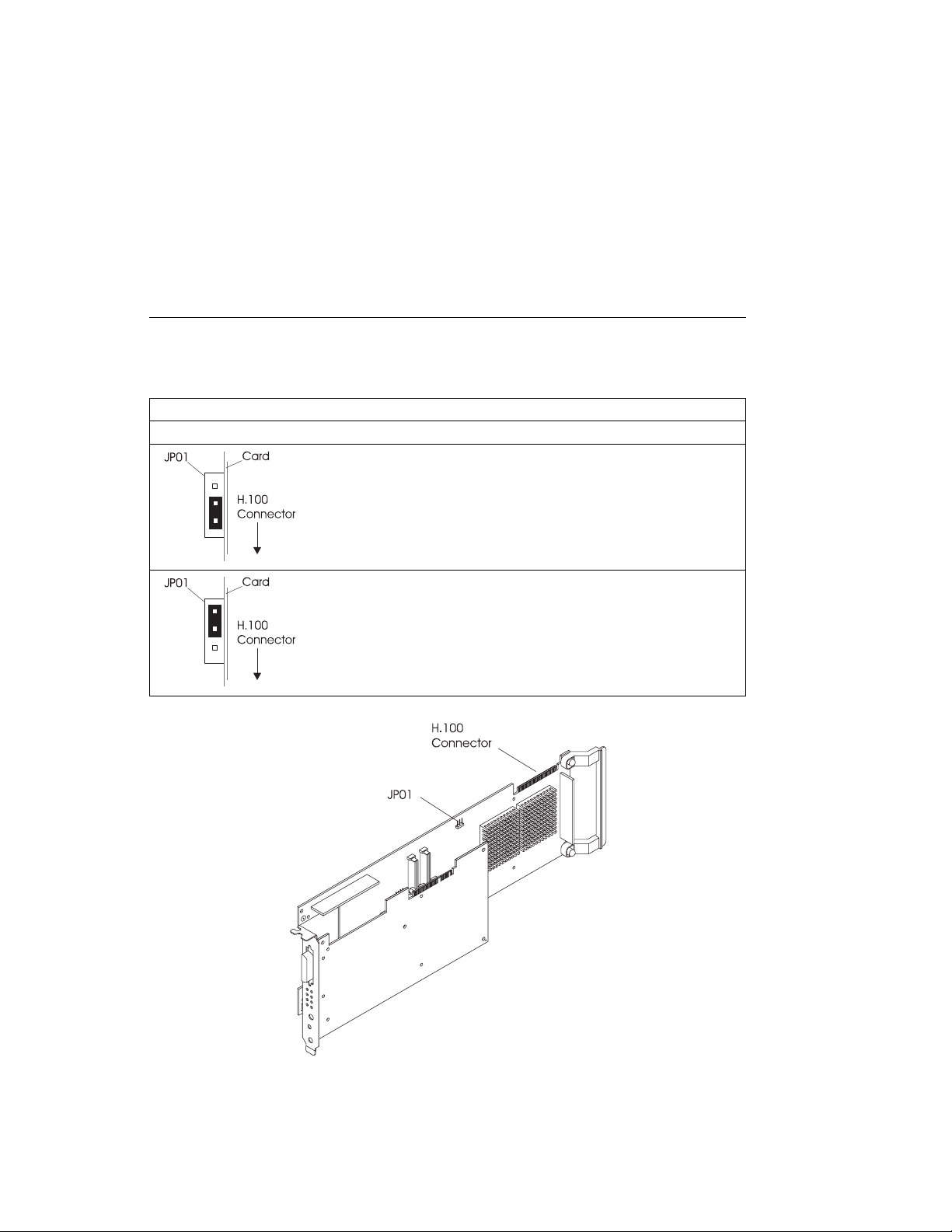
Jumper Installation Information
Before installing this adapter, set jumper JP01 as follows:
Table 1-1. Jumper Installation Information
Jumper Positions Condition
If the adapter to be installed is connected to either end of the H.100
Cable (see the illustration on page 1-5), the jumper must be installed
as shown in the illustration to the left.
If the adapter to be installed is the only IBM ARTIC960RxD in the
system, then set the jumper as shown in the illustration to the left.
This is the factory setting.
If the adapter to be installed is NOT connected to either end of the
H.100 Cable (see the illustration on page 1-5), then set the jumper as
shown in the illustration to the left.
Chapter 1. Installation 1-3
Page 14

Installing the IBM ARTIC960RxD Quad Digital Trunk PCI Adapter
The following procedure describes how to install the IBM ARTIC960RxD Quad DTA
into the system unit. The steps may vary depending on your system unit. Refer to
the documentation that came with your system unit for detailed instructions on
performing the following procedures:
Note: Insure that the jumpers are set as described in “Jumper Installation
Information” on page 1-3
Be sure to perform necessary shutdown procedures to protect your system and
data.
Shut down your system unit
Remove the system unit covers
Install the IBM ARTIC960RxD Quad DTA into your system unit
Install the H.100 cable if necessary
Replace the system unit covers
1-4 Installation and User's Guide
Page 15
IBM ARTIC960RxD Quad Digital Trunk PCI Adapter Internal Cabling
Multi-drop cable assemblies are used to connect the internal busses on up to four
Quad Digital Trunk PCI Adapters. There are three top card cables, RW, RX and RY.
RW is used to connect multiple IBM ARTIC960RxD Quad DTAs to each other as well
as other adapters with H.100 connectors, see below. Cables RX and RY are used to
connect Quad DTAs or other adapters that have H.100 connectors as well as
adapters that have SC-Bus connectors, see the following two pages.
These cables are just long enough to connect four adapters that support H.100
connectors in adjacent slots.
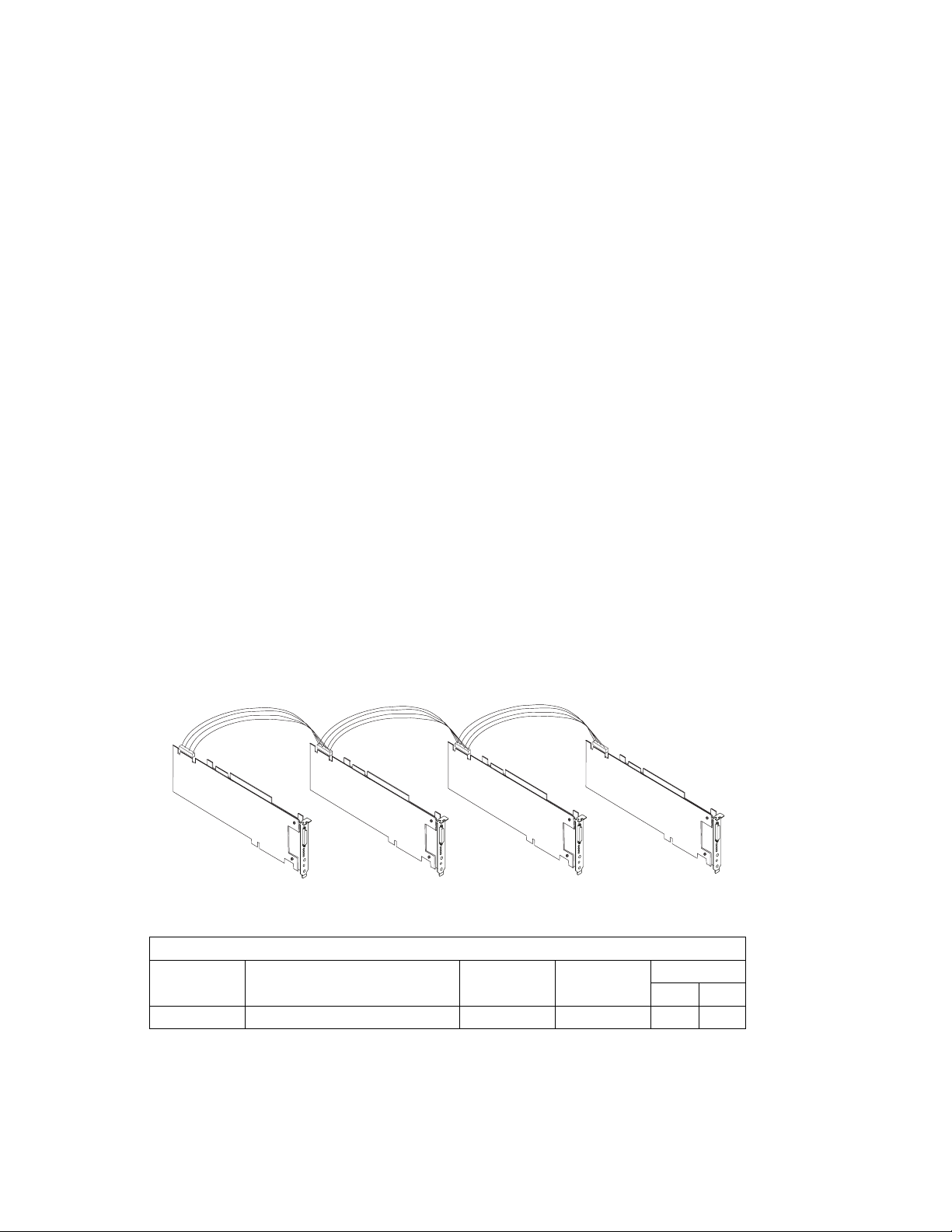
H.100, 4-Drop Cabling: The IBM ARTIC960RxD Quad DTAs have H.100 top
card connectors.
The following figure illustrates the internal cabling for the IBM ARTIC960RxD Quad
DTAs with the H.100 top card connectors cabled together. Up to four IBM
ARTIC960RxD Quad DTAs are supported and must be in adjacent slots. Refer to
Table 1-1 on page 1-3 to position the jumper on JP01 on the base card.
RW
H.100, 4-Drop Ribbon Cabling
Table 1-2. H.100, 4-drop Internal Cable Information
Cable
Letter
RW H.100, 4-drop Internal Cable 08L1215 2877 0.127 0.417
Chapter 1. Installation 1-5
Cable Name/ Description Part
Number
Feature
Code
Length
m ft
Page 16
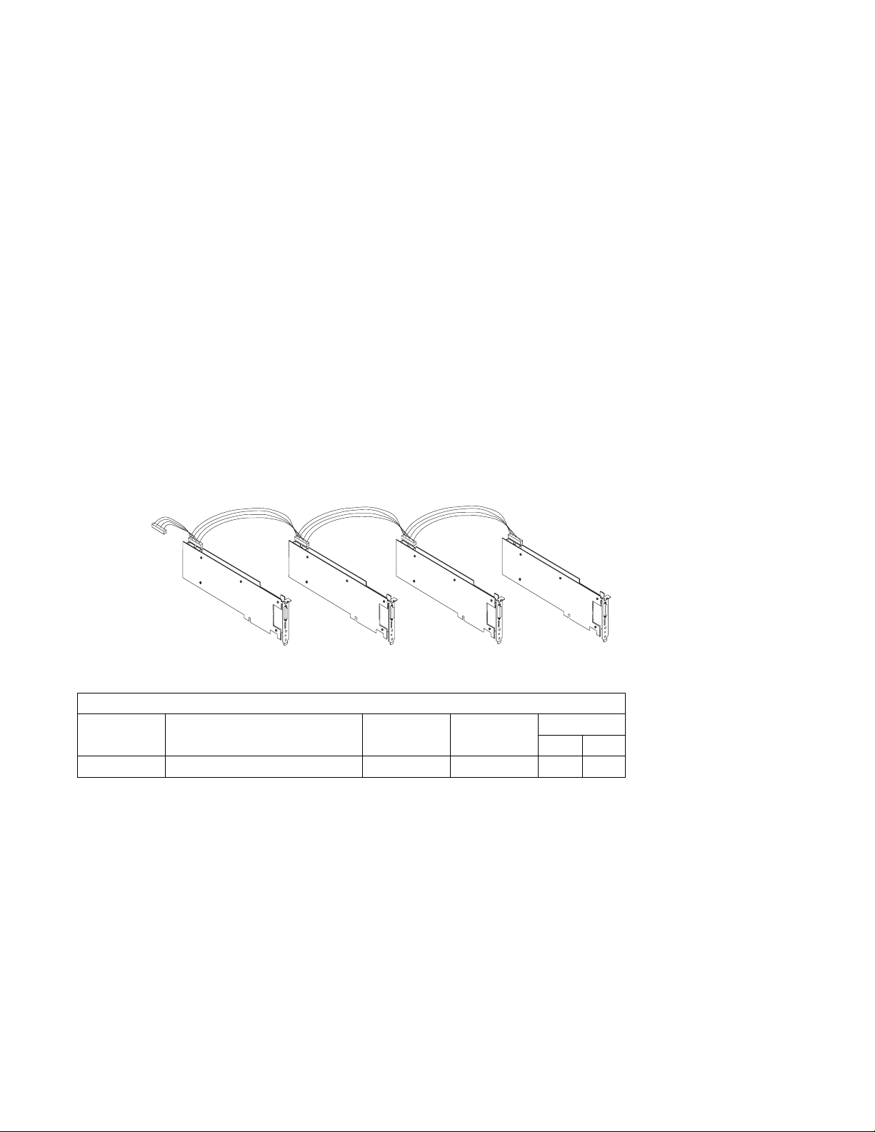
SC-Bus, 5-Drop Cable: This Multi-drop cable assembly is used to connect up to
four adapters with SC-Bus internal connectors. It has an additional SC-Bus
connector which connects to cable RY. See “H.100, 4-Drop Cable With SC-Bus
Converter Connector” on page 1-7. This allows adapters with SC-Bus connectors to
be used with the IBM ARTIC960RxD Quad DTAs and with other adapters that have
H.100 top card connectors.
The following figure illustrates the internal cabling for up to four adapters with
SC-Busses and an additional SC-Bus connector which goes to the H.100 4-drop
Cable with SC-Bus converter connector. Refer to Table 1-1 on page 1-3 to position
the jumper on JP01 on the base card.
SC-Bus
to H.100 Bus
with SC-Bus
Converter
Connector
SC-Bus, 5-Drop Cable
Table 1-3. SC-Bus, 5-Drop Cable Information
Cable
Letter
RX SC-Bus, 5-Drop Cable 08L1217 2878 0.176 0.58
Cable Name/ Description Part
RX
Number
Feature
Code
Length
m ft
1-6 Installation and User's Guide
Page 17
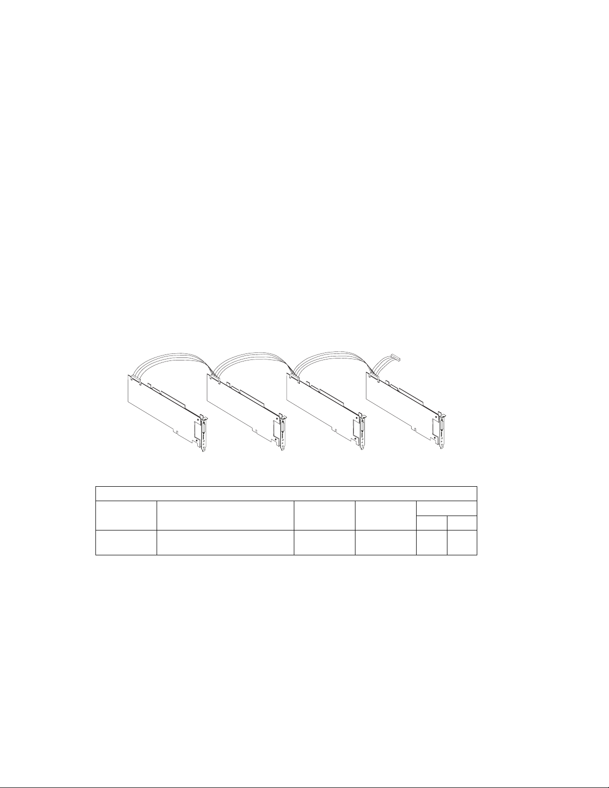
H.100, 4-Drop Cable With SC-Bus Converter Connector: This Multi-drop
cable assembly is used to connect the internal busses on up to four IBM
ARTIC960RxD Quad DTAs with H.100 connectors. It has an additional connector to
connect to cable RX. See “SC-Bus, 5-Drop Cable” on page 1-6. This allows
adapters with SC-Bus connectors to be used with the IBM ARTIC960RxD PCI
Adapters and other adapters that have H.100 connectors.
The following figure illustrates the internal cabling for up to four IBM ARTIC960RxD
Quad DTAs with an additional connector to the SC-Bus 5-drop cable with SC-Bus
converter connector. Refer to Table 1-1 on page 1-3 to position the jumper on
JP01 on the base card.
SC-Bus
RY
H.100, 4-Drop cable with SC-Bus Converter Connector
Table 1-4. H.100, 4-Drop Cable with SC-Bus Converter Connector Cable Information
Cable
Letter
RY H.100, 4-Drop Cable with SC-Bus
Cable Name/ Description Part
Number
08L1219 2879 0.176 0.58
Converter Connector
Feature
Code
Converter
Connector
Length
m ft
Note: This cable is referred to as the Four-drop, H.100 Cable with SC-Bus
Converter in other publications associated with this cable.
Chapter 1. Installation 1-7
Page 18

Connecting Telecommunications Cables
Attention
Do not connect or handle the cable during a lightning storm.
The following instructions assume that you have the adapter in the system unit and
are ready to attach an Telecommunications Cables.
1. Align the 36-pin connector of the cable with the 36-pin connector at the rear of
the IBM ARTIC960RxD Quad DTA.
2. Depress the latch buttons on either side of the cable connector and firmly press
the cable connector into the 36-pin connector.
3. Release the latch buttons and make sure that the cable connector latches are
securely seated.
If required, connect a lightning protection device to the other ends of the cable.
Refer to the instructions that came with the device.
At the very least, the grounding strap on the lightning protection device should be
connected to an earth-ground on or near the computer.
4. Connect one or more of the four ports of the optional cable to the target device.
Each connector is marked with its port number.
Telecommunications ports are numbered 0,1,2 and 3 whereas some software (such
as DirectTalk/AIX) refers to the ports as 'Trunks 1,2,3 and 4'.
Note: Moving the system unit with a cable attached can dislodge an adapter. If any
adapter or card becomes dislodged while power is applied, proceed as
follows:
1. Turn off the computer and unplug all power cords.
2. Remove the system unit cover.
3. Loosen the expansion-slot screw of the dislodged adapter. Press down
on the top edge of the adapter to reseat it. Then, re-tighten the
expansion-slot screw.
4. Reinstall the system unit cover and replug power cords.
5. Turn on the computer.
1-8 Installation and User's Guide
Page 19

Operating System Support
If the DirectTalk for AIX software is used, the IBM ARTIC960 RTE is automatically
installed as part of the DirectTalk for AIX installation. Proceed to Chapter 2.
Downloading the Operating System Support Programs and Diagnostics
The adapter diagnostic program and the support programs for AIX can be obtained
through the World Wide Web or a Bulletin Board System (BBS).
The IBM ARTIC960 Run Time Enviornment (RTE) Version 1.3 (or later) Support for
AIX is shipped with the adapter.
Downloading from the Web: Do the following.
1. Using a Web browser of your choice, type:
http://wwprodsoln.bocaraton.ibm.com/artic/file_rep.html
2. Select the operating-system support you want.
3. Download the Program file.
4. Download the Installation/file creation instructions file, and follow the steps for
installing and configuring the product support.
Chapter 1. Installation 1-9
Page 20

Downloading from the BBS: Do the following.
1. Check that your modem settings are as follows:
Data Bit 8
Parity Bit N
Stop Bit 1
2. Dial the U.S.A. number 561-443-8222.
3. Select the operating system support you want.
4. Select a Transfer Protocol supported by your communications software.
5. View on-line or download the Readme/Instruction file.
6. Follow the instructions in the readme file for downloading and installing the
program support that comes with the diagnostics.
Obtaining Operating System Software when Web/BBS Support Is
Unavailable: For those who are unable to retrieve the files from either the Web or
BBS, support is provided by telephone or E-mail.
For telephone assistance (U.S.A. ONLY), call:
1-800-426-4968 and ask for technical support for the IBM ARTIC960.
For E-mail assistance, send to:
artic@us.ibm.com
1-10 Installation and User's Guide
Page 21

Chapter 2. Product Description
The IBM ARTIC960RxD Quad DTA is a full-size, 32-bit, PCI adapter. It consists of a
base adapter (the IBM ARTIC960RxD PCI Adapter) and a mezzanine card (the Quad
T1/E1 DTA).
Part Numbers
The following table lists the part numbers for the field-replaceable units (FRUs)
associated with this adapter.
Table 2-1. IBM ARTIC960RxD Quad DTA Part Numbers
Description Part Number
IBM ARTIC960RxD PCI Adapter 87H3734
Quad T1/E1 DTA (includes the adapter bracket) 09J8829
Chapter 2. Product Description 2-1
Page 22

Features and Function
These sections describe the base adapter and the mezzanine card.
IBM ARTIC960RxD PCI Adapter—Base Adapter
The base adapter provides high-function control of I/O operations and serves to
off-load input/output tasks from the system microprocessor. The base adapter has
the following standard features:
An Intel 80960RD processor (clock-doubled RP) running at up to 33 MHz
(depends on the PCI clock on the system bus)
On-board memory, which is available only to the processor on the base adapter
and cannot be accessed through the system bus.
– 4 MB extended-data-output (EDO) dynamic random-access memory (DRAM)
– Flash read-only memory (ROM)
A 32-bit system-bus PCI interface
Two Texas Instruments TMS320C6201 digital signal processors (DSPs),
operating at a clock cycle of 200 MHz. Each DSP has 512 KB of
synchronous-burst static random-access memory (SBSRAM) and can process up
to 1 600 000 000 instructions per second.
A PLX technology 9080, which provides the 80960RD processor with access to
the SC4000s and DSPs using memory-mapped I/O and DMA access.
Two VLSI VP06967 SC4000 chips, which provide an interface to the H.100
connector. One chip provides an interface between the DSPs and the H.100
connector; the other provides an interface between the mezzanine card and the
H.100 connector.
An ECTF H.100 connector operating in SC-bus compatible mode
PMC connectors, which support attaching any mezzanine card with a PCI
mezzanine card (PMC) interface
2-2 Installation and User's Guide
Page 23

IBM Quad T1/E1 DTA—Mezzanine Card
The mezzanine card provides an interface to four T1 or E1 external network trunk
lines.
The mezzanine card has the following features:
A PMC bus interface to the base adapter
Four Siemens PEB2255-LH framing and line control (FALC) chips, which provide
the interface functions for the four trunk lines
A PLX Technology 9050 chip, which provides an interface from the PMC bus to
the FALC and SC4000 chips
A VLSI VP06967 SC4000 chip, which provides an interface from the FALCs to
the H.100 connector. This feature is used only in non-DSP line-interface
applications.
An ECTF H.100 connector operating in SC-bus compatible mode. This feature is
used only in non-DSP line-interface applications.
Passive components and a 36-pin connector, which allow the FALCs to interface
to the four external trunks
A relay, which can be used for an external alarm or indicator
Chapter 2. Product Description 2-3
Page 24

Component Locations
The following shows some component locations on the IBM ARTIC960RxD Quad
DTA.
2-4 Installation and User's Guide
Page 25

Specifications
The following describes the physical attributes, environmental conditions, and
electrical requirements for the adapter.
Size
Length: 350 millimeters (13.75 inches)
Height: 131 millimeters (5 inches)
Environment
Air Temperature:
Operating: 0°C through 55°C (32°F through 131°F)
Non-Operating: −40°C through 60°C (−40.°F through 140°F)
Humidity:
Operating: 5% through 95%.
Wet Bulb Temperature: 29°C (84.2°F)
Electrical
Power Requirements
+3.3 V dc, 0 A
+5 V dc, 4.0 A (maximum)
+12 V dc, 0 A
−12 V dc, 0 A
Optional Cables
Optional cable assemblies are available for the IBM ARTIC960RxD Quad DTA. See
Chapter 6, “Cables and Connectors” for information.
Operating System Support Programs and Publications
To help programmers develop additional applications for the IBM ARTIC960RxD
Quad DTA, a set of operating system packages containing the drivers and utilities to
support a particular operating system is available on the World Wide Web (Web). To
download from the Web, see “Operating System Support” on page 1-9.
The IBM ARTIC960 Run Time Enviornment (RTE) Version 1.3 (or later) Support for
AIX is shipped with adapter.
Chapter 2. Product Description 2-5
Page 26

2-6 Installation and User's Guide
Page 27

Chapter 3. Removing and Reinstalling the Quad T1/E1 DTA
This chapter contains information on removing and reinstalling the Quad T1/E1 DTA
from the base adapter. In this section, the IBM ARTIC960RxD PCI Adapter is
referred to as the base adapter, and the Quad T1/E1 DTA is referred to as the
mezzanine card.
Removing the Quad T1/E1 DTA
The following procedure describes how to remove the mezzanine card from the base
adapter. The procedure varies depending on your system unit. Refer to the
documentation that came with your system unit for detailed instructions on
performing the following procedures:
Shutting down your system unit
Removing the system unit covers
Removing an adapter from the system unit
Note:
Be sure to hold the IBM ARTIC960RxD Quad DTA by the edges only; do not
touch the component pins or solder joints.
If more than one adapter is installed, remove the H.100 cable and note the state
of JP01.
1. Remove the four mounting screws from the base adapter as shown in the
following figure. (The two cards are still held together by the PMC connector.)
2. Carefully separate the connector on the mezzanine card from the connector on
the base adapter using a gentle rocking motion.
Chapter 3. Removing/Reinstalling the Quad T1/E1 DTA 3-1
Page 28

Reinstalling the Quad T1/E1 DTA
The following instructions assume that you have the base adapter out of the system
unit and are ready to install the mezzanine card.
Before You Begin
Verify that the jumper on the base adapter is set properly (see page 1-3).
1. Align the connector on the mezzanine card with the PMC connector on the base
adapter.
Attention:
When the base adapter and the mezzanine card are properly aligned, the top of
the voltage keying pin on the base adapter fits into the voltage key opening on
the mezzanine card.
2. Firmly press the mezzanine card and the base adapter connectors together.
3. Install the four mounting screws; then tighten the screws.
4. Follow the procedure “Jumper Installation Information” on page 1-3.
3-2 Installation and User's Guide
Page 29

Chapter 4. Installing the Device Driver on the RS/6000 SP System
In an SP, you need to do on each node what you normally do on a standalone
system. You must make the installation files available and then install them on all
the relevant nodes.
Perform the following tasks on the Control Workstation. You should not need to
telnet
command. If not, refer to the
Administration Guide
Technical Reference
If you are unable to utilize the "dsh" command because of the setup at your site,
then you will have to telnet to each node and perform the steps below, omitting the
"dsh" prefix.
Check System Pre-Requisites
or
rlogin
to the individual SP nodes. You need to be familiar with the
Parallel System Support Program for AIX:
or
Parallel System Support Program for AIX: Command and
.
1. Log into the Control Workstation as a root.
2. Go to a temporary directory by typing:
cd /tmp
dsh
at the system prompt, then press Enter.
3. Make a "working collective" file containing a list of the relevant nodes on
which you want to perform the update in preparation for the dsh command.
Type the following, press Enter after each line:
cat > group1
nodename1
nodename2
nodename3......
CTRL-D
export WCOLL=/tmp/group1
4. Test the working collective by typing:
dsh date
then press Enter. The results should look similar to:
nodename1: Wed Apr 1ð 1ð:37:46 EDT 1996
nodename2: Wed Apr 1ð 1ð:37:46 EDT 1996
nodename3: Wed Apr 1ð 1ð:37:47 EDT 1996
nodename4: Wed Apr 1ð 1ð:37:48 EDT 1996
Chapter 4. Installing the Device Driver on the SP System 4-1
Page 30

If not, examine your nodelist file ./group1 and also ensure that the Kerberos
ticket is current to permit "rsh" to be performed. If not, you may need to
refresh it. The System Administrator should also be able to help you with
Kerberos initialization. If not, consult your support center.
If you only need to do a few nodes, use the dsh -w host1,host2,host3...
command format to explicitly exercise groups of nodes rather than using the
working collective.
5. Determine if the AIX operating system on each relevant node is at the
required level by typing:
dsh oslevel
-OR -
dsh -w <host1,host2> oslevel
at the prompt, then press Enter. <host1,host2> is a list of the hostnames for
the nodes which the adapter will be installed on.
6. The required AIX Level is: 4.2.1 and higher.
If the nodes are NOT at a supported AIX level, upgrade the AIX level on the
nodes. Contact the System Administrator for assistance.
7. Determine if the PSSP level on each node is at the required level by typing:
/usr/lpp/ssp/bin/splstdata -G -b
then press Enter. The results are in a form similar to the following:
node# hostname hdw_enet_addr srvr response install_disk
last_install_image last_install_time next_install_image lppsource_name
pssp_ver
----------------------------------------------------------------------- 1 eionð1.ppd.pok.i ð8ðð5A75A6D4 ð disk hdiskð
default Thu_Dec__4_ð9:ð7:23 default <lppsource>
<pssp level>
<lppsource> is the lppsource name for the node. <pssp level> is the pssp
level installed on the node.
8. The required PSSP level is: 2.4 and higher.
If the nodes are NOT at a supported PSSP level, upgrade the PSSP level on
the nodes. Contact the System Administrator for help.
4-2 Installation and User's Guide
Page 31

9. Record the name that appears below lppsource_name for each node on
which the adapters are being installed; you use this later.
__________________________________
10. Check if the device driver is installed in the lppsource directory by typing:
cd /spdata/sys1/install/<lppsource_name>/lppsource
at the system prompt. <lppsource_name> was recorded in the previous
step. Once in this directory, type:
ls devices.artic96ð\
at the system prompt to see if the fileset is in lppsource directory.
11. If the device driver is not in the lppsource directory, proceed to section
“Install Software on the Control Workstation” on page 4-4 to install the
software.
12. Update the SPOT (Shared Product Object Tree) by:
a. Type
smitty nim_res_op
at the system prompt. The Resource Name panel displays with
boot resources boot
highlighted.
b. Move the cursor down until the
SPOT resource
should look like:
SPOT resource
is highlighted. The
spot_AIX432 resources spot
The format of the spot name is: spot_<lppsource_name>.
<lppsource_name> was recorded in a previous step.
c. When the
SPOT resource
is highlighted, press Enter to select this
option. The Network Install Operation to Perform panel displays
with the reset option highlighted for selection.
d. Move the cursor until the cust option is highlighted and press Enter
to select this option. The Customize a SPOT panel displays with
the Source of Install Images highlighted for selection.
e. Press F4 to display the list of Install Images and select the
appropriate lppsource.
f. Move the cursor until the appropriate lppsource is displayed. For
example:
lppsource_AIX432 resources lpp_source
Chapter 4. Installing the Device Driver on the SP System 4-3
Page 32

g. Move the cursor until the fileset names and type:
devices.artic96ð
h. Press Enter to start the SPOT update. This operation can take up to
15 minutes.
13. Check if the software is already installed by typing:
dsh "lslpp -l devices.artic96ð\ 2>&1" |more
at the system prompt.
14. If the device driver is already installed on the Node, contact your service
provider to have the adapter installed.
15. If the device driver is not installed on the Node, proceed to section “Install
Device Drivers on the SP Nodes” on page 4-6.
Install Software on the Control Workstation
Note: If your system is "partitioned" i.e. there are more than one operating system
among the nodes, you may only install this adapter in nodes that have 4.2.1 and
higher.
1. If you are not logged into the Control Workstation as a root user, log in now.
You may also need to export the working collective. Refer to section “Check
System Pre-Requisites” on page 4-1.
2. Select the appropriate operating system media.
Table 4-1. Device Driver Sources
AIX 4.3.x IBM ARTIC960 RTE Disk Kit
AIX 4.2.1 IBM ARTIC960 RTE Disk Kit
3. Insert the installation media into the Control Workstation's drive.
4. Transfer the files to the Control Workstation's lppsource, as follows:
a. Type
smitty bffcreate
then press Enter.
b. Select the input device/directory. Press F4 then move the cursor to
the appropriate input device and press Enter.
4-4 Installation and User's Guide
Page 33

c. Move the cursor to the "SOFTWARE package to copy" option and
press F4 to select the software to be installed. Use the F7 key to
select the following device driver(s):
No Prerequisite Driver
devices.artic96ð
at the system prompt, then press Enter.
d. Move the cursor down to "DIRECTORY for storing software package"
and enter the appropriate lppsource destination directory:
/spdata/sys1/install/<lppsource_name>/lppsource
using the <lppsource_name> you recorded earlier.
e. Press Enter to begin copying the files.
Note: This step may take several minutes as the directory table of
contents is updated.
5. Update the SPOT (Shared Product Object Tree) by:
a. Type
smitty nim_res_op
at the system prompt. The Resource Name panel displays with
boot resources boot
highlighted.
b. Move the cursor down until the
SPOT resource
should look like:
SPOT resource
is highlighted. The
spot_AIX432 resources spot
The format of the spot name is: spot_<lppsource_name>.
<lppsource_name> was recorded in a previous step.
c. When the
SPOT resource
is highlighted, press Enter to select this
option. The Network Install Operation to Perform panel displays
with the reset option highlighted for selection.
d. Move the cursor until the cust option is highlighted and press Enter
to select this option. The Customize a SPOT panel displays with
the Source of Install Images highlighted for selection.
e. Press F4 to display the list of Install Images and select the
appropriate lppsource.
f. Move the cursor until the appropriate lppsource is displayed. For
example:
lppsource_AIX432 resources lpp_source
Chapter 4. Installing the Device Driver on the SP System 4-5
Page 34

g. Move the cursor until the fileset names and type:
devices.artic96ð
h. Press Enter to start the SPOT update. This operation can take up to
15 minutes.
6. Proceed to section “Install Device Drivers on the SP Nodes”
Install Device Drivers on the SP Nodes
1. Make sure that the lppsource directory is exported to the Nodes by typing:
showmount -e
at the system prompt. The result should be something of the form:
/spdata/sys1/install/AIX432/lppsource (everyone)
2. If the directory is not exported, you may temporarily export the directory by
typing:
exportfs -i /spdata/sys1/install/<lppsoruce_name>/lppsource
3. NFS Mount the lppsource directory by typing:
dsh mount <controlwks>:
/spdata/sys1/install/<lppsource_name>/lppsource /mnt
at the system prompt. <controlwks> is the name of the Control Workstation
known for the Nodes. <lppsource_name> is the name you recorded earlier in
section “Check System Pre-Requisites” on page 4-1.
4. Perform a preview of the files to be installed on the nodes by typing:
dsh "installp -p -acqXd /mnt device driver 2>&1" | more
at the system prompt.
the adapter. The list includes:
No Prerequisite Driver
devices.artic960
5. Then perform the device driver installation by typing:
dsh "installp -acqXd /mnt device driver 2>&1" | more
at the system prompt.
6. If the device driver is already installed on the node, contact your service
provider to have the adapter installed.
4-6 Installation and User's Guide
device driver
device driver
is the filesets that must be installed for
is defined in the previous step.
Page 35

Chapter 5. Troubleshooting
This chapter discusses how to troubleshoot possible problems with the base adapter.
If the DirectTalk for AIX is installed follow the steps in the DirectTalk for AIX guide for
running diagnostics.
Problem Determination Procedures
For system testing information, refer to the documentation that came with your
computer.
If you performed the diagnostic tests because of a suspected communications
problem and have successfully completed the tests without an error message,
additional testing may be required on the following:
Host computer or device with which you are trying to communicate (such as a
printer)
An attached communications device, such as a modem
Communications cable
To test the IBM ARTIC960RxD PCI Adapter or the Quad T1/E1 DTA, refer to the
operating system support programs you downloaded from the Web or BBS (see
“Operating System Support” on page 1-9).
If you cannot isolate the problem, have the system unit serviced.
Diagnostic Testing
The diagnostic program is designed to prompt you through making a wrap test
selection, either to test the Quad T1/E1 DTA using the 36-pin connector at the Quad
T1/E1 DTA, or to test one of the ports at the end of the cable.
Chapter 5. Troubleshooting 5-1
Page 36

Diagnostic Wrap Plugs
Table 5-1 lists the part numbers of the wrap plugs used during wrap testing. The
part number is printed on the wrap plug.
To test the telephone jack cable, use a short telephone patch cord. Connect the
patch cord between the
you are testing.
Table 5-1. Wrap Plugs
Description Part Number
36-pin wrap plug
(connector at the adapter)
RJ-48 plug cable wrap 87H3588
DB-15 cable wrap plug 34F0876
BNC cable wrap plug
(for grounded and ungrounded cables)
Transmit (Tx)
and the
87H3502
61F5394
Receive (Rx)
connectors of the port
5-2 Installation and User's Guide
Page 37

Chapter 6. Cables and Connectors
Optional cable assemblies (similar to the one in the following figure) are available for
the Quad T1/E1 DTA. They are designed to provide four ports of one electrical
interface.
Chapter 6. Cables and Connectors 6-1
Page 38

T1 RJ-48, E1 RJ-48, T1 DB-15, and E1 DB-15
These cable assemblies consist of a 36-pin male connector at one end of a
cable that branches into four individual cables, each of which provides access
to one of four independent ports.
E1 BNC (grounded and ungrounded)
These cable assemblies split first to four cables. Then, each of the four cables
splits into two, resulting in eight connectors. There is a transmit (Tx) connector
and a receive (Rx) connector for each of the four ports.
The following table lists the cable name, FRU number, and feature code (FC)
number for each optional cable.
Table 6-1. FRU and Feature Code (FC) Numbers for Optional Cables
Numbers
Cable Name
T1 RJ-48 87H3518 2709
E1 RJ-48 87H3515 2710
T1 DB-15 100 Ohm Balanced 87H3793 2871
T1 DB-15 100 Ohm Extension 54F0740 2872
E1 DB-15 120 Ohm Balanced 87H3791 2873
E1 DB-15 120 Ohm Extension 05F2045 2874
E1 DB-15 120 Ohm Balanced Isolated 47L8826 --E1 BNC 75 Ohm Unbalanced/Grounded 87H3521 2875
E1 BNC 75 Ohm Unbalanced/Ungrounded 87H3629 2876
4-Drop H.100 08L1215 2877
4-Drop SCBus 08L1217 2878
4-Drop H.100/SCBus Converter 08L1219 2879
FRU FC
Surge protection cables are also available in two versions: RJ-48 (FRU 87H3651)
and BNC (FRU 87H3656).
6-2 Installation and User's Guide
Page 39

Port Speeds
The Quad T1/E1 DTA supports four ports running simultaneously at a maximum data
rate of 2048000 bps (bits per second) duplexed. The following table shows the
maximum port speed supported for each electrical interface.
Table 6-2. Quad T1/E1 DTA Port Speeds
Electrical Interface Maximum Speed (per port)
T1 1 544 000 bps
E1 2 048 000 bps
Chapter 6. Cables and Connectors 6-3
Page 40

Connector Pin Numbers and Assignments
This section provides pin numbering and signal assignments for each of the optional
cables. For each cable, a table shows the pin assignments for the 36-pin connector
and the correlation to the four port connectors. Each signal is identified as input (I)
or output (O), as viewed from the Quad T1/E1 DTA.
36-pin Connector
The individual signals for all ports connect to the Quad T1/E1 DTA through the
36-pin connector at the rear of the card. The following shows the male 36-pin
connector at one end of the cable.
Note: A relay on the mezzanine card can be used to generate an external alarm.
The standard cables do not provide support for this function. For more
information, refer to the technical reference for the IBM ARTIC960RxD Quad
Digital Trunk PCI Adapter, which is available on the Web (see “Operating
System Support Programs and Publications” on page 2-5).
6-4 Installation and User's Guide
Page 41

RJ-48 Jack Connector
The following illustration shows an RJ-48 jack connector. Table 6-3 lists the pin
assignments for the T1 and E1 electrical interfaces. The “x” in the signal name is
the number of the port. The ID is 9h for the T1; 1h for the E1.
Table 6-3. RJ-48 Connector Pin Assignments
36-pin Connector
Signal Name I/O
TX1_x O 33 29 23 19 04
TX2_x O 34 30 24 20 05
FGND_x --- 16 12 08 04 06,03
RX1_x I 35 31 25 21 01
RX2_x I 36 32 26 22 02
RJ-48
Connector0 1 2 3
FGND --- Housing Housing
Chapter 6. Cables and Connectors 6-5
Page 42

DB-15 Connector
The following illustration shows a DB-15 connector. Table 6-4 lists the pin
assignments for the T1 and E1 electrical interfaces. The “x” in the signal name is
the number of the port. The ID is 7h for the T1; 2h for the E1.
Table 6-4. DB-15 Connector Pin Assignments
36-pin Connector
Signal Name I/O
TX1_x O 33 29 23 19 01
TX2_x O 34 30 24 20 09
FGND_x --- 16 12 08 04 02,04
RX1_x I 35 31 25 21 11
RX2_x I 36 32 26 22 03
FGND --- Housing Housing,
DB-15
Connector0 1 2 3
08, 15
6-6 Installation and User's Guide
Page 43

E1 BNC Connector (Grounded)
The following illustration shows a BNC connector. Table 6-5 lists the pin
assignments for the E1 BNC electrical interface. The “x” in the signal name is the
number of the port. The ID is 8h for the E1 grounded BNC.
Table 6-5. E1 BNC (Grounded) Connector Pin Assignments
36-pin Connector
Signal Name I/O
TX1_x O 33 29 23 19 TX inner
RX1_x I 35 31 25 21 RX inner
FGND,
TX2_x,
RX2_x
--- Housing, 20, 22, 24, 26, 30, 32, 34, 36 TX and RX
BNC
Connector0 1 2 3
conductor
conductor
outer
conductors
Chapter 6. Cables and Connectors 6-7
Page 44

E1 BNC Connector (Ungrounded)
The following illustration shows a BNC connector. Table 6-6 lists the pin
assignments for the E1 BNC electrical interface. The “x” in the signal name is the
number of the port. The ID is Ch for the E1 ungrounded BNC.
Table 6-6. E1 BNC Connector (Ungrounded) Pin Assignments
36-pin Connector
Signal Name I/O
TX1_x O 33 29 23 19 TX inner
RX1_x I 35 31 25 21 RX inner
RX2_x I 36 32 26 22 RX outer
FGND,
TX2_x
--- Housing, 20, 24, 30, 34 TX outer
BNC
Connector0 1 2 3
conductor
conductor
conductor
conductor
6-8 Installation and User's Guide
Page 45

Appendix A. Communications Statements
The following statement applies to this product. The statement for other products
intended for use with this product appears in their accompanying documentation.
Federal Communications Commission (FCC) Statement
Note: This equipment has been tested and found to comply with the limits for a
Class A digital device, pursuant to Part 15 of the FCC Rules. These limits are
designed to provide reasonable protection against harmful interference when the
equipment is operated in a commercial environment. This equipment generates,
uses, and can radiate radio frequency energy and, if not installed and used in
accordance with the instruction manual, may cause harmful interference to radio
communications. Operation of this equipment in a residential area is likely to cause
harmful interference in which case the user will be required to correct the
interference at his own expense.
Properly shielded and grounded cables and connectors must be used in order to
meet FCC emission limits. Neither the provider nor the manufacturer are responsible
for any radio or television interference caused by using other than recommended
cables and connectors or by unauthorized changes or modifications to this
equipment. Unauthorized changes or modifications could void the user's authority to
operate the equipment.
This device complies with Part 15 of the FCC Rules. Operation is subject to the
following two conditions: (1) this device may not cause harmful interference, and (2)
this device must accept any interference received, including interference that may
cause undesired operation.
European Union (EU) Statement
This product is in conformity with the protection requirements of EU Council Directive
89/336/EEC on the approximation of the laws of the Member States relating to
electromagnetic compatibility. The manufacturer cannot accept responsibility for any
failure to satisfy the protection requirements resulting from a non-recommended
modification of the product, including the fitting of option cards supplied by third
parties. Consult with your dealer or sales representative for details on your specific
hardware.
This product has been tested and found to comply with the limits for Class A
Information Technology Equipment according to CISPR 22 / European Standard EN
55022. The limits for Class A equipment were derived for commercial and industrial
Appendix A. Preface A-1
Page 46

environments to provide reasonable protection against interference with licensed
communication equipment.
Attention: This is a Class A product. In a domestic environment this product may
cause radio interference in which case the user may be required to take adequate
measures.
International Electrotechnical Commission (IEC) Statement
This product has been designed and built to comply with IEC Standard 950.
United Kingdom Telecommunications Safety Requirements
This equipment is manufactured to the International Safety Standard EN60950 and
as such is approved in the UK under the General Approval Number
NS/G/1234/J/100003 for indirect connection to the public telecommunication network.
The network adapter interfaces housed within this equipment are approved
separately, each one having its own independent approval number. These interface
adapters, supplied by the manufacturer, do not use or contain excessive voltages.
An excessive voltage is one which exceeds 70.7 V peak ac or 120 V dc. They
interface with this equipment using Safe Extra Low Voltages only. In order to
maintain the separate (independent) approval of the manufacturer's adapters, it is
essential that other optional cards, not supplied by the manufacturer, do not use
main voltages or any other excessive voltages. Seek advice from a competent
engineer before installing other adapters not supplied by the manufacturer.
Avis de conformité aux normes du ministère des Communications du Canada
Cet appareil numérique de la classe A respecte toutes les exigences du Réglement
sur le matériel brouilleur du Canada.
Canadian Department of Communications Compliance Statement
This Class A digital apparatus meets the requirements of the Canadian
Interference–Causing Equipment Regulations.
A-2 Installation and User's Guide
Page 47

VCCI Statement
The following is a summary of the VCCI Japanese statement in the box above.
This is a Class A product based on the standard of the Voluntary Control Council for
Interference by Information Technology Equipment (VCCI). If this equipment is used
in a domestic environment, radio disturbance may arise. When such trouble occurs,
the user may be required to take corrective actions.
Electromagnetic Interference (EMI) Statement - Taiwan
The following is a summary of the EMI Taiwan statement above.
Warning: This is a Class A product. In a domestic environment this product may
cause radio interference in which case the user will be required to take adequate
measures.
Appendix A. Preface A-3
Page 48

Radio Protection for Germany
Dieses Gerät ist berechtigt in Übereinstimmung mit Dem deutschen EMVG vom
9.Nov.92 das EG–Konformitätszeichen zu führen.
Der Aussteller der Konformitätserklärung ist die IBM Germany.
Dieses Gerät erfüllt die Bedingungen der EN 55022 Klasse A. Für diese von
Geräten gilt folgende Bestimmung nach dem EMVG:
Geräte dürfen an Orten, für die sie nicht ausreichend entstört sind, nur mit
besonderer Genehmigung des Bundesministers für Post und Telekommunikation
oder des Bundesamtes für Post und Telekommunikation betrieben werden. Die
Genehmigung wird erteilt, wenn keine elektromagnetischen Störungen zu erwarten
sind.
(Auszug aus dem EMVG vom 9.Nov.92, Para.3, Abs.4)
Hinweis
Dieses Genehmigungsverfahren ist von der Deutschen Bundespost noch nicht
veröffentlicht worden.
Telecommunications Statements
FCC Part 68 Compliance Information
The IBM ARTIC960RxD Quad DTA complies with Part 68 of the FCC rules. The
label located on the back side of the adapter contains, among other information, the
FCC registration number for this equipment. If requested, provide this information to
your telephone company. The card has an SOC code of 6.0N and FIC codes
04DU9-BN, 04DU9-DN, 04DU9-IKN, 04DU9-ISN, and 04DU9-IZN.
The IBM ARTIC960 4-Port T1 RJ-48 Cable, which uses USOC jack RJ-48, is an
FCC-compliant cable and modular jack available for the adapter. The adapter and
cable are designed to be connected to the telephone network or premises wiring
using a compatible modular plug that is Part 68-compliant.
If the IBM ARTIC960RxD Quad DTA causes harm to the telephone network, the
telephone company may discontinue your service temporarily. If possible, they will
notify you in advance. But if advance notice is not practical, you will be notified as
soon as possible. You will be advised of your right to file a complaint with the FCC.
A-4 Installation and User's Guide
Page 49

Your telephone company may make changes in its facilities, equipment, operations,
or procedures that could affect the proper operation of your equipment. If they do,
you will be given advance notice so as to give you an opportunity to maintain
uninterrupted service.
If trouble is experienced with this equipment, for repair or warranty information, in the
United States, call IBM at 1-800-IBM-SERV. In Canada, call IBM at 1-800-465-6600.
No repairs can be performed by the customer.
Canada Telecommunications Statement
NOTICE: The Industry Canada label identifies certified equipment. This certification
means that the equipment meets certain telecommunications network protective,
operational and safety requirements as prescribed in the appropriate Terminal
Equipment Technical Requirements document(s). The Department does not
guarantee the equipment will operate to the user’s satisfaction.
Before installing this equipment, users should ensure that it is permissible to be
connected to the facilities of the local telecommunications company. The equipment
must also be installed using an acceptable method of connection. The customer
should be aware that compliance with the preceding conditions might not prevent
degradation of service in some situations.
Repairs to certified equipment should be coordinated by a representative designated
by the supplier. Any repairs or alterations made by the user to this equipment, or
equipment malfunctions, may give the telecommunications company cause to
request the user to disconnect the equipment.
Users should ensure for their own protection that the electrical ground connections of
the power utility, telephone lines and internal metallic water pipe system, if present,
are connected together. This precaution may be particularly important in rural areas.
Caution: Users should not attempt to make such connections themselves, but
should contact the appropriate electric inspection authority, or electrician, as
appropriate.
This equipment uses a CA81A telephone jack.
Appendix A. Preface A-5
Page 50

Australian Telecommunications Statement
ATTENTION:
This card must be connected to TNV Telecommunications equipment or networks
using the E1 120 Ohm Balanced DB-15 Isolated cable only. On the 75 ohm
connection, the E1 120 Ohm Balanced DB-15 Isolated cable and an ACA approved
balun must be used.
New Zealand Telecommunications Statement
ATTENTION: New Zealand Users
The NZ Telecom Telepermit No. PTC 414/98/008 has been issued for direct
connection to the Telecom network via its E1 120-ohm balanced interface only. The
75-ohm interface may be used for connection to other equipment (e.g. PBX) but not
directly to the Telecom network.
Norway and Sweden Telecommunications Statement
ATTENTION:
This card must only be connected to the Telecommunications Network using the E1
120-ohm Balanced DB-15 Isolated cable.
A-6 Installation and User's Guide
Page 51

Index
Numerics
36-pin connector 2-3
36-pin D-shell connector 6-4
36-pin wrap plug 5-2
A
attaching an optional cable 1-8
C
cable FRU and part numbers 6-2
component locations 2-4
connecting an optional cable 1-8
D
data rates, interface 6-3
DB-15 connector 6-6
description, base adapter 2-1
device drivers, installing 1-2
digital signal processor (DSP) 2-2
documentation, base adapter 2-5
downloading diagnostics 1-9
downloading operating system
support 1-9
DSP (digital signal processor) 2-2
E
E1 BNC connector (grounded) 6-7
E1 BNC connector (ungrounded) 6-8
EDO DRAM, base adapter 2-2
F
FALC (framing and line control) 2-3
features and function, base
adapter 2-2
framing and line control (FALC) 2-3
H
H.100 bus 2-3
H.100 connector 2-2
hardware requirements 1-1
I
illustration 2-4
installing device drivers 1-2
interface port speeds 6-3
ISO 9000 ix
J
jumper positions 1-3
L
lightning protection 1-8
M
mezzanine card features 2-3
microprocessor, base adapter 2-2
O
operating system support 1-9, 2-5
optional cables 6-1
P
part numbers 2-1
PMC connector 2-2
problem determination procedures 5-1
Index X-1
Page 52

R
related information ix
removing the mezzanine card 3-1
RJ-48 cable wrap 5-2
RJ-48 jack connector 6-5
ROM, base adapter 2-2
S
specifications 2-5
synchronous-burst static
random-access memory
(SBSRAM) 2-2
T
telecommunications statements A-4
terminology ix
trademarks ix
troubleshooting 5-1
trunk lines 2-3
W
Web address 1-9, 2-5
X-2 Installation and User's Guide
Page 53

Reader's Comments — We'd Like to Hear From You
IBM ARTIC960RxD Quad DTA Installation and User's Guide
Order Number: 41L5825
Overall how satisfied are you with the information in this book?
Very
Satisfied Satisfied Neutral Dissatisfied
Overall Satisfaction ØØØØ Ø
Very
Dissatisfied
How satisfied are you that the information in this book is:
Very
Satisfied Satisfied Neutral Dissatisfied
Accurate ØØØØ Ø
Complete ØØØØ Ø
Easy to find ØØØØ Ø
Easy to understand ØØØØ Ø
Well organized ØØØØ Ø
Applicable to your tasks ØØØØ Ø
Very
Dissatisfied
Please tell us how we can improve this book:
Thank you for your response. May we contact you? Ø Yes Ø No
When you send comments to us, you grant us a nonexclusive right to use or
distribute your comments in any way we believe appropriate without incurring
any obligation to you.
X-3
Page 54

Cut or Fold
Along Line
Fold and Tape
Fold and Tape
Please do not Staple
BUSINESS REPLY MAIL
POSTAGE WILL BE PAID BY ADDRESSEE
Information Development
Department H6DS-9561
11400 Burnet Road
Austin, TX 78758-3493
Please do not Staple
Fold and Tape
NO POSTAGE
NECESSARY
IF MAILED IN THE
UNITED STATES
Fold and Tape
X-4 Installation and User's Guide
Cut or Fold
Along Line
Page 55

Page 56

IBM
Part Number: 41L5825
Printed in the United States of America
on recycled paper containing 10%
recovered post-consumer fiber.
41L5825
 Loading...