

Page 1

IBM
IBM ARTIC186
8-Port PCI Adapter
Guide to Operations
Page 2

Page 3

IBM ARTIC186
8-Port PCI Adapter
Guide to Operations
IBM
Page 4

Important Safety
See “Safety Information” on page B-2 before installing or removing an adapter.
Note
Before using this information and the product it supports, be sure to read the information under Appendix B, “Notices” on
page B-1.
Third Edition (July 1999)
This edition replaces and makes obsolete the previous edition, 87H3541, and the October 1998 edition.
Copyright International Business Machines Corporation 1998, 1999. All rights reserved.
Note to U.S. Government Users — Documentation related to restricted rights — Use, duplication or disclosure is subject to
restrictions set forth in GSA ADP Schedule Contract with IBM Corp.
Page 5

Contents
About This Book ................................................. v
Who Should Read This Book ........................................... v
Related Information . . . . . . . . . . . . . . . . . . . . . . . . . . . . . . . . . . . . . . . . . . . . . . . . v
Chapter 1. Product Description . . . . . . . . . . . . . . . . . . . . . . . . . . . . . . . . . . . . . . . 1-1
Adapter Part Numbers .............................................. 1-1
Features and Functions ............................................. 1-2
Optional Cables . . . . . . . . . . . . . . . . . . . . . . . . . . . . . . . . . . . . . . . . . . . . . . . . . . 1-2
Specifications . . . . . . . . . . . . . . . . . . . . . . . . . . . . . . . . . . . . . . . . . . . . . . . . . . . 1-2
Manuals and Software Support ......................................... 1-3
Chapter 2. Installation Requirements and Instructions ......................... 2-1
Hardware Requirements . . . . . . . . . . . . . . . . . . . . . . . . . . . . . . . . . . . . . . . . . . . . . 2-1
Hardware Tools . . . . . . . . . . . . . . . . . . . . . . . . . . . . . . . . . . . . . . . . . . . . . . . . 2-1
Preparing for Installation ............................................. 2-1
Configuration Records . . . . . . . . . . . . . . . . . . . . . . . . . . . . . . . . . . . . . . . . . . . . 2-2
Handling Static-Sensitive Devices ...................................... 2-2
Jumpers . . . . . . . . . . . . . . . . . . . . . . . . . . . . . . . . . . . . . . . . . . . . . . . . . . . . 2-3
Set Communication Clock Jumpers ..................................... 2-4
Interface Selection Jumpers ......................................... 2-6
Installation . . . . . . . . . . . . . . . . . . . . . . . . . . . . . . . . . . . . . . . . . . . . . . . . . . . . . 2-7
Step 1. Installing the ARTIC186 8-Port PCI Adapter ........................... 2-7
Step 2. Downloading the Diagnostics and Operating-System Programs ................ 2-8
Step 3. Running Diagnostics to Verify Installation ............................ 2-9
Step 4. Connecting the Cable ........................................ 2-9
Step 5. Setting Up Files ........................................... 2-9
Chapter 3. Replacing the ARTIC186 8-Port PCI Adapter ........................ 3-1
Removing the Adapter .............................................. 3-1
Installing the New Adapter ........................................... 3-2
Chapter 4. Troubleshooting . . . . . . . . . . . . . . . . . . . . . . . . . . . . . . . . . . . . . . . . . 4-1
Problem Determination . . . . . . . . . . . . . . . . . . . . . . . . . . . . . . . . . . . . . . . . . . . . . 4-1
Diagnostic Wrap Plugs .............................................. 4-1
Diagnostic Testing . . . . . . . . . . . . . . . . . . . . . . . . . . . . . . . . . . . . . . . . . . . . . . . . 4-2
Chapter 5. Cables and Connectors ..................................... 5-1
Cable Information . . . . . . . . . . . . . . . . . . . . . . . . . . . . . . . . . . . . . . . . . . . . . . . . . 5-1
Connector Information . . . . . . . . . . . . . . . . . . . . . . . . . . . . . . . . . . . . . . . . . . . . . . 5-2
Appendix A. Special Configuration Information for DOS and OS/2 ................. A-1
Creating an ICAPARM.PRM File ........................................ A-1
Adding an ICAPARM.PRM File Entry .................................... A-1
Base I/O Address Considerations ...................................... A-2
Example 1: One ARTIC186 Adapter .................................... A-2
Example 2: Multiple ARTIC186 Adapters ................................. A-3
Changing Your CONFIG.SYS File ....................................... A-3
Ctrl+Alt+Del Reset Considerations ....................................... A-3
Selecting an Interrupt Level for the ARTIC186 8-Port PCI Adapter .................... A-4
Copyright IBM Corp. 1998, 1999 iii
Page 6

Appendix B. Notices . . . . . . . . . . . . . . . . . . . . . . . . . . . . . . . . . . . . . . . . . . . . . . B-1
Trademarks and Service Marks ........................................ B-1
Safety Information . . . . . . . . . . . . . . . . . . . . . . . . . . . . . . . . . . . . . . . . . . . . . . . . B-2
Required Electronic Emission and Connectivity Notices .......................... B-3
Class A Federal Communications Commission Statement ....................... B-3
Industry Canada Compliance Statement .................................. B-3
United Kingdom . . . . . . . . . . . . . . . . . . . . . . . . . . . . . . . . . . . . . . . . . . . . . . . . B-3
European Union (EU) Electromagnetic Compatibility Directive ..................... B-3
Germany . . . . . . . . . . . . . . . . . . . . . . . . . . . . . . . . . . . . . . . . . . . . . . . . . . . . B-4
Japan . . . . . . . . . . . . . . . . . . . . . . . . . . . . . . . . . . . . . . . . . . . . . . . . . . . . . . B-5
Index . . . . . . . . . . . . . . . . . . . . . . . . . . . . . . . . . . . . . . . . . . . . . . . . . . . . . . . . X-1
iv ARTIC186 8-Port PCI Adapter GTO
Page 7

About This Book
This book contains the following information for the ARTIC186 8-Port PCI Adapter:
Description of the adapter
Installation requirements and instructions
Configuration table and information
Jumper setting information
Problem determination procedures
Optional cables and connector information
Lists of replacement parts
Who Should Read This Book
This book is written for an experienced computer operator or a person who sets up, uses, or programs the
ARTIC186 8-Port PCI Adapter with IBM computer products.
Related Information
Operating and installation documentation provided with your personal computer system.
Reference, service, and diagnostic documentation available for your computer system.
Operating system-specific information, for example DOS and Windows NT.
Copyright IBM Corp. 1998, 1999 v
Page 8

vi ARTIC186 8-Port PCI Adapter GTO
Page 9
Chapter 1. Product Description
The ARTIC186 8-Port PCI Adapter, with supporting software, enables the attachment of a
PCI-bus-compatible personal computer system to have up to eight serial communications links through
optional cables.
| Note: The ARTIC186 8-Port PCI Adapter cannot be installed in a PCI slot that supports spread spectrum.
The ARTIC186 8-Port PCI Adapter has its own microprocessor and memory, allowing it to perform
communications functions.
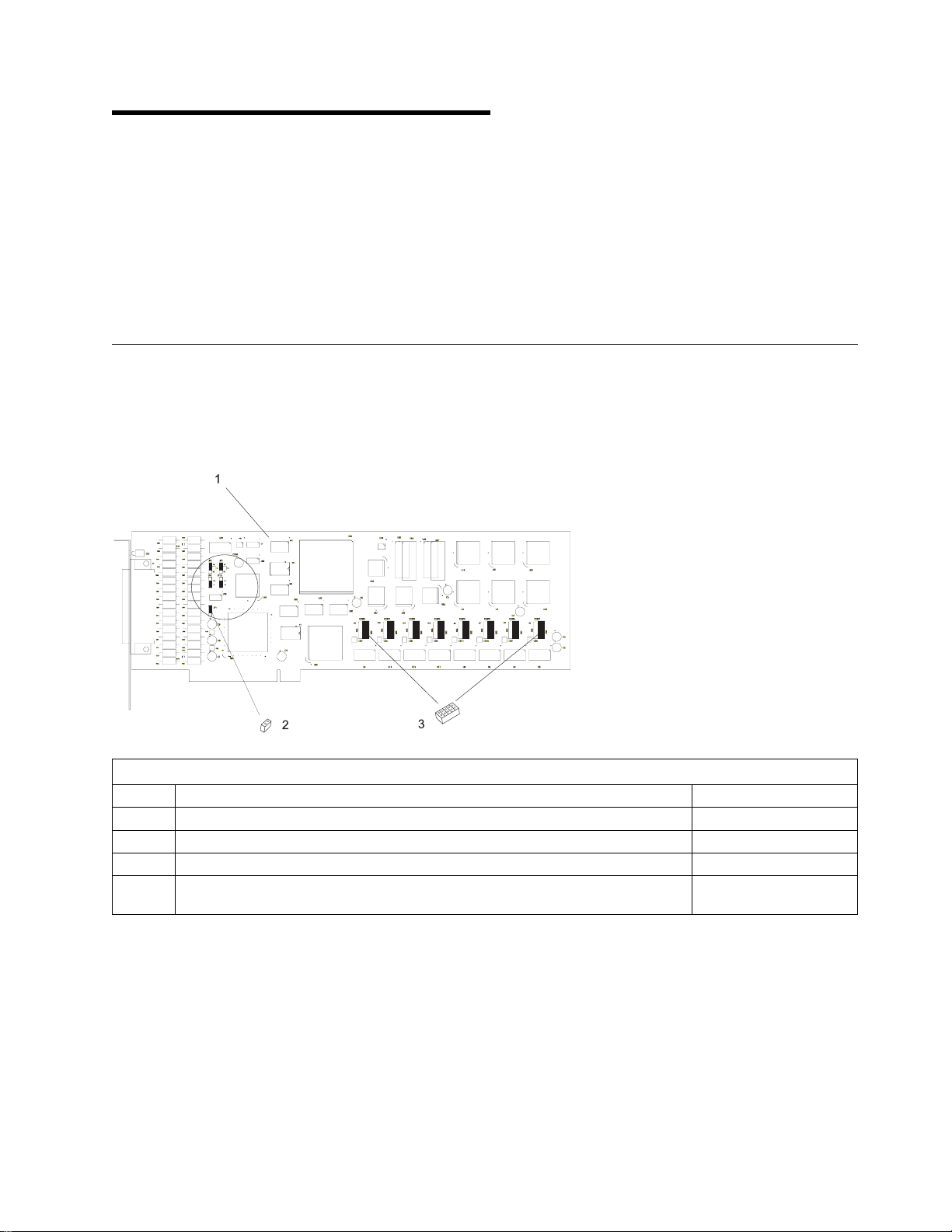
Adapter Part Numbers
Service replacement parts are called field-replaceable units (FRUs) and must be ordered by their part
numbers. The following lists the part numbers for the FRUs associated with the ARTIC186 8-Port PCI
Adapter. For cable part numbers, see Table 5-1 on page 5-1. For wrap-plug part numbers, see
“Diagnostic Wrap Plugs” on page 4-1.
Table 1-1. Part Numbers
Index Description Part Numbers
1 ARTIC186 8-Port PCI Adapter 87H3670
2 Jumper, 2-position (included with miscellaneous parts kit)
3 Jumper, 2x5-position (included with miscellaneous parts kit)
| Not
| Miscellaneous parts kit (contains indexes 2 and 3)| 53G0719
| shown
Copyright IBM Corp. 1998, 1999 1-1
Page 10

Features and Functions
The ARTIC186 8-Port PCI Adapter provides:
An 80C186 microprocessor
1 MB of dual-ported, dynamic random-access memory (DRAM)
16 KB of read-only memory, providing power-on self-test and diagnostic functions
Eight communications ports of RS-232 or RS-485 interface (or combinations of both) that can, through
optional cables, support one port at a maximum of 38.4 kbps duplexed, or all eight ports at up to 9.6
kbps duplexed
Note: Because the RS-422 interface is a subset of the RS-485 interface, applications that use
RS-422 are compatible with applications that use RS-485.
Multiple card installation capability
Optional Cables
The ARTIC186 8-Port PCI Adapter has two cable options. The two options are electrically the same, and
both provide connectors for eight devices. They do, however, offer different physical characteristics. For
more information, see Chapter 5, “Cables and Connectors.”
Specifications
Physical
Length: 342.9 millimeters (13.5 inches)
Width: 17.5 millimeters (0.7 inches)
Height: 106.7 millimeters (4.2 inches)
Weight: 23 grams (0.5 pounds)
Environment
Air temperature:
Operating: 0 to 60°C (32 to 140°F)
Non-Operating: 0 to 60°C (32 to 140°F).
Humidity:
Operating: 5% through 90%.
Electrical
Optimum Voltages: Maximum Current:
+4.8 V dc to +5.25 V dc 1.5 A
-5.5 V dc to -4.5 V dc 0 mA
+11.3 V dc to +12.7 V dc 175 mA
-10.8 V dc to -13.2 V dc 150 mA
1-2 ARTIC186 8-Port PCI Adapter GTO
Page 11

Manuals and Software Support
Manuals and software support (operating-system and diagnostic programs) are available for downloading
at:
http://www.radisys.com/support/artic/ibm
Product Description 1-3
Page 12

1-4 ARTIC186 8-Port PCI Adapter GTO
Page 13

Chapter 2. Installation Requirements and Instructions
This chapter provides the following information.
Hardware requirements
Setup and preparation instructions for installing the ARTIC186 8-Port PCI Adapter
Installation instructions
Download instructions for the software/microcode
Hardware Requirements
The ARTIC186 8-Port PCI Adapter requires the following hardware:
A full-length, 5-volt, 32-bit slot. The ARTIC186 8-Port PCI Adapter can be installed in any
PCI-compliant computer.
Notes:
| 1. The ARTIC186 8-Port PCI Adapter cannot be installed in a PCI slot that supports spread
| spectrum.
2. The FCC statement in this manual may be different than the FCC statement in the manual that
came with your system. Use the FCC statement in this manual for the system unit that will
contain the ARTIC186 8-Port PCI Adapter.
| One of the following IBM ARTIC cables (or equivalent). The cable dimensions are listed in Chapter 5,
“Cables and Connectors.”
– 8-Port Direct Modem Attach Cable
| – Portmaster 8-Port Cable
Hardware Tools
Medium-size flat-blade screwdriver
Optional:
– Medium screwstarter
– 3/16-inch nutdriver
– 1/4-inch nutdriver.
Preparing for Installation
To prepare for installing the ARTIC186 8-Port PCI Adapter, complete the Configuration Record table
(Table 2-1 on page 2-2) as you proceed through this chapter and review the following.
How to handle static-sensitive devices (page 2-2)
Jumper setting information (starting on page 2-3)
Interface selection information (page 2-6)
Copyright IBM Corp. 1998, 1999 2-1
Page 14

Configuration Records
Record the specifics of your configuration in Table 2-1. The information you record is referenced
whenever you run the diagnostics for the ARTIC186 8-Port PCI Adapter.
Table 2-1. Configuration Records
8-Port PCI Adapter
Description
Port 0
(232 or 485) ___ ___ ___ ___
Port 1
(232 or 485) ___ ___ ___ ___
Port 2
(232 or 485) ___ ___ ___ ___
Port 3
(232 or 485) ___ ___ ___ ___
Port 4
(232 or 485) ___ ___ ___ ___
Port 5
(232 or 485) ___ ___ ___ ___
Port 6
(232 or 485) ___ ___ ___ ___
Port 7
(232 or 485) ___ ___ ___ ___
0 1 2 3
Handling Static-Sensitive Devices
Components for your ARTIC186 8-Port PCI Adapter can be damaged by static discharges. To prevent
this damage, your ARTIC186 8-Port PCI Adapter is wrapped in an anti-static bag. Observe the following
precautions when handling the adapter:
Keep the adapter in its anti-static bag until you are ready to install it.
Make the least possible movement with your body to minimize the electrostatic charges created by
contact with clothing fibers, carpets, and furniture.
If possible, keep one hand on the computer chassis when you are inserting or removing an adapter.
Always turn the computer off before removing an adapter from the system unit.
Do not touch the printed circuit, connector pins, or components. Where possible, hold the adapter by
its plastic end pieces or by its edges, but do not touch the metal edge connectors.
Do not place the adapter on the system unit cover or on a metal table. The cover and metal table
increase the risk of damage because they make a discharge path from your body through the adapter.
2-2 ARTIC186 8-Port PCI Adapter GTO
Page 15

Jumpers
Figure 2-1. Location of Jumpers
Load Region Jumper: The ARTIC186 8-Port PCI Adapter can be configured to operate in either of
two regions of memory: below 1 MB or above 1 MB. During power-on self-test (POST), the adapter
requests memory and other system resources.
The operating system being used determines which window is needed. For example, the DOS operating
system cannot directly access memory devices above 1 MB. On the other hand, operating systems, such
as Windows NT, operate in the protected mode and can access memory devices in the regions above
1 MB.
The following is JP1, the load-region jumper.
Window below 1 MB: The adapter requests memory resources below 1 MB. Use this setting if the computer is
operating in a DOS environment
Window above 1 MB: The adapter requests resources above 1 MB. Use this setting for operating systems that
operate in the protected mode (such as Windows NT).
Installation Requirements and Instructions 2-3
Page 16

Set Communication Clock Jumpers
Set the communication-clock jumpers for port 0 (JP2 and JP4) and port 1 (JP3 and JP13) as shown. The
jumper settings are described beginning on page 2-4.
Figure 2-2. Communication Jumper Settings
Transmit Clock Jumpers: The transmit-clock jumpers determine whether the transmit clocks for
ports 0 and 1 are an output (the data-terminal equipment provides the clock) or an input (the
data-communications equipment provides the clock).
The following shows the settings for transmit clock jumpers.
Description
Output clock to external
device
Input clock from external
device
Port 0
JP4
Port 1
JP13
2-4 ARTIC186 8-Port PCI Adapter GTO
Page 17

Receive Clock Jumpers: The receive-clock jumpers determine whether the external receive clock
for ports 0 and 1 is driven by:
A remote clock
The transmit clock divided by 16
The transmit clock divided by 32
Note: If the transmit clock for port 0 or 1 is set as the input clock, the corresponding receive-clock jumper
(JP2 or JP3) must be set to the remote-clock position.
If the transmit clock for port 0 or 1 is set as an output clock, the corresponding receive-clock
jumper (JP2 or JP3) must be set to the divided-by-16 or divided-by-32 position.
The following shows the settings for the receive-clock jumpers.
Description
Remote clock
Transmit clock divided
by 16
Transmit clock divided
by 32
Port 0
JP2
Port 1
JP3
Installation Requirements and Instructions 2-5
Page 18

Interface Selection Jumpers
The ARTIC186 8-Port PCI Adapter has a set of jumpers used to select the serial interface used by each
port. The interface is selected on a port-by-port basis for each of the eight ports. The jumper selects
either an RS-232 or RS-485/422 interface for a given port; the default position is RS-232.
The following shows the location of the interface-selection jumpers.
Note: RS-422 is a subset of RS-485.
Set Port Protocol (RS-232 or RS-485): Position the shunt (a 2x5-position jumper) to select the
interface: RS-485 or RS-232. Each port can be configured independent of the setting of the other ports.
RS-485/422 RS-232
2-6 ARTIC186 8-Port PCI Adapter GTO
Page 19

Installation
The hardware installation process for the ARTIC186 8-Port PCI Adapter includes completing the following
procedures:
Installing the ARTIC186 8-Port PCI Adapter in the system unit
Downloading the operating system support and diagnostic programs (page 2-8)
Running diagnostics to verify installation (page 2-9)
Connecting the optional cable (page 2-9)
Setting up configuration files (page 2-9)
Step 1. Installing the ARTIC186 8-Port PCI Adapter
Use the following steps as general information for installing your ARTIC186 8-Port PCI Adapter. For
specific adapter installation instructions, consult the operating manual or the installation and setup manual
for your specific personal computer system.
1. Turn the computer off.
2. Unplug the power cords from the wall outlets.
3. Remove the cable-retaining brackets from the rear of the system unit and display.
4. Disconnect all cables from the rear of the system unit.
5. Use a flat-blade screwdriver or 1/4-inch nutdriver to remove the cover mounting screws (if present)
from the system unit.
6. Remove the system unit cover.
7. Locate an available expansion slot in your system unit.
| Note: The ARTIC186 8-Port PCI Adapter cannot be installed in a PCI slot that supports spread
| spectrum.
8. Use a flat-blade screwdriver or a 3/16-inch nutdriver to remove the screw that holds the expansion-slot
cover in place. Lift the expansion-slot cover from the system unit.
9. Hold the ARTIC186 8-Port PCI Adapter (still wrapped in the anti-static bag) in one hand and touch a
metal part of your system unit with the other hand. This places your body, the adapter, and the
system unit at the same ground potential, preventing an accidental static discharge.
10. Carefully remove the adapter from the anti-static bag. Be sure to grasp circuit boards by the edges
only; do not touch the component pins or solder joints.
Installation Requirements and Instructions 2-7
Page 20

11. Install the adapter by holding it by the top and firmly pressing it into the expansion slot.
12. Align the slot in the card-retaining bracket with the hole in the rear panel of the system unit.
13. Insert and tighten the screw to secure the card-retaining bracket to the rear panel of the system unit.
14. If you have other adapters (or options) to install, do so now. Refer to the Operating and Installation
documentation provided with your computer system if more information is required for other adapters
or options.
15. Replace the system unit cover.
16. Reconnect all cables previously removed from the system unit.
17. Plug all power cords into electrical outlets.
Step 2. Downloading the Diagnostics and Operating-System Programs
Download the adapter diagnostic and operating-system support programs from:
http://radisys.com/support/artic/ibm
For telephone assistance, call: 1-800-237-5511. At the Voice Response Unit, enter 0 (ignore all other
options).
For e-mail assistance, send to: artic@radisys.com
2-8 ARTIC186 8-Port PCI Adapter GTO
Page 21

Step 3. Running Diagnostics to Verify Installation
Before you continue with “Step 4. Connecting the Cable,” see “Diagnostic Testing” on page 4-2 to test the
ARTIC186 8-Port PCI Adapter in an Intel-based IBM-compatible system.
Step 4. Connecting the Cable
Use the following steps to connect your optional cable.
Note: The optional cables are described on page 5-1.
DANGER
Lightning protection. Do not connect or handle the cable during a lightning storm.
1. Align the connector of the cable with the adapter connector at the rear of the system unit. It can
attach to the connector only one way.
2. Firmly press the cable onto the connector.
3. Insert and tighten the screw at each side of the connector on the cable.
4. Connect your device to the other end of the cable.
You have completed the installation of the ARTIC186 8-Port PCI Adapter hardware; continue with “Step 5.
Setting Up Files.”
Step 5. Setting Up Files
See Appendix A, “Special Configuration Information for DOS and OS/2” for important setup information on
creating an ICAPARM.PRM file and changing the CONFIG.SYS file. The changes are necessary for the
correct operation of your ARTIC186 8-Port PCI Adapter.
Installation Requirements and Instructions 2-9
Page 22

2-10 ARTIC186 8-Port PCI Adapter GTO
Page 23

Chapter 3. Replacing the ARTIC186 8-Port PCI Adapter
Use these procedures to remove a failing adapter and to install a replacement.
Removing the Adapter
Note: The following steps are an example of adapter removal. For instructions specific to your computer,
refer to the hardware and service information that came with your computer.
1. Turn the computer off.
2. Disconnect the power cords from the electrical outlets.
3. Disconnect all cables from the rear of the system unit.
4. Remove the system unit cover.
5. Open the card retainer by loosening the screw.
6. Remove the adapter retaining screw.
7. Grasp the adapter by the top corners and lift straight up.
Copyright IBM Corp. 1998, 1999 3-1
Page 24

Installing the New Adapter
Note: The following steps are an example of adapter replacement. For instructions specific to your
computer, refer to the hardware and service information that came with your computer.
1. Make any necessary switch or jumper settings before installing the adapter.
2. Insert the adapter in an expansion slot.
3. Press down firmly on the adapter to seat the connector.
4. Install the adapter retaining screw.
5. Reinstall the system unit cover.
3-2 ARTIC186 8-Port PCI Adapter GTO
Page 25

Chapter 4. Troubleshooting
| This chapter contains step-by-step instructions that can help you determine if your ARTIC186 8-Port PCI
| Adapter is operating properly.
To test the ARTIC186 8-Port PCI Adapter after completing the initial installation, see “Diagnostic
Testing” on page 4-2.
To view the individual parts of the ARTIC186 8-Port PCI Adapter and obtain part numbers, see
“Adapter Part Numbers” on page 1-1.
If you suspect you have a problem, do the following.
1. Check electrical connections (that is, cable connections between devices, cable connections between
devices and wall outlets, and wall outlet condition).
2. Perform diagnostics.
Problem Determination
For system testing information, refer to the documentation supplied with your computer.
If you performed the diagnostic tests because of a suspected communications problem and the diagnostic
program completed the testing without indicating an error, check the following:
The computer or device at the other end (make sure that it is operating properly)
The base adapter
Any intermediate communication device, such as a modem
The communication cable
Note: If you are unsure of a problem area, perform the system-unit diagnostics first before proceeding
with the ARTIC186 8-Port PCI Adapter diagnostics.
Diagnostic Wrap Plugs
Diagnostic wrap tests can be performed at the connector on the adapter or at a specific port connector on
the cable. Use the menu to select the location for wrap testing. The following table lists the part numbers
for the cable-end wrap plug (the wrap plug used depends on the configuration of the serial port).
Table 4-1. Wrap Plugs
Description Part Number
78-pin wrap plug 16F2478
25-pin wrap plug RS-232 (ports 0 and 1) 6425494
25-pin wrap plug RS-232 (ports 2 and 7) 09F1799
25-pin wrap plug RS-485 (ports 0 and 7) 6425494
Copyright IBM Corp. 1998, 1999 4-1
Page 26

Diagnostic Testing
The diagnostic program prompts for the type of wrap test you want to make. You can either test the
adapter using the wrap plug at the 78-pin connector on the adapter, or test the individual ports using a
wrap plug at the end of the cable (testing the individual ports allows you to verify the operation of the
cable also).
The 78-pin connector at the adapter
If you choose to test the adapter without testing the cable, connect the 78-pin wrap plug to the
connector on the adapter. After connecting the wrap plug, start the diagnostic program (if it is not
already running) and respond to the test program prompts for this interface. The diagnostic program
runs the tests without any further intervention.
One or more ports of the cable
If you choose to test the operation of one or more of the ports to the end of the cable, connect the
appropriate wrap plug to the end of the cable for the port you want to test.
Note: Disconnect all connectors on the cable at the device end (not at the adapter) before starting
any wrap tests.
After connecting the wrap plug, start the diagnostic program. When prompted, select the port you
want to test. The diagnostic program runs the test on that port without further intervention.
After the program completes the tests, it prompts for the next test to run. Repeat the procedure for
each port you want to test.
4-2 ARTIC186 8-Port PCI Adapter GTO
Page 27

Chapter 5. Cables and Connectors
This chapter contains cable and connector information.
Cable Information
The following cables are available as options. The two options are functionally the same. However, the
modem-attach cable provides the eight connectors on cables, and the interface cable has the eight
connectors on a breakout block.
8-Port Direct Modem Attach Cable
The cable length is 1.8 meters (6 feet) long. It has a 78-pin female connector on one end and eight
cables that have a 25-pin male connector at the other end.
| Multiport Interface Cable
The cable length is 3.0 meters (9.8 feet) long. It has a 78-pin female connector on one end and eight
25-pin male connectors in a breakout box at the other end.
Note: These are the same cables that are used on the IBM ARTIC Multiport adapter.
1
2
The following are the part numbers for the cables used by the ARTIC186 8-Port PCI Adapter. For
wrap-plug part numbers, see “Diagnostic Wrap Plugs” on page 4-1.
Table 5-1. Part Numbers for the Optional Cables
Index Description Part Number
1 8-Port Direct Modem Attachment cable 71G3494
| 2| Multiport Interface cable| 00F5531
Copyright IBM Corp. 1998, 1999 5-1
Page 28

Connector Information
The figure below shows the pin numbering for the 78-pin and 25-pin connectors. The connectors and pin
| numbering are the same for the 8-Port Direct Modem Attach Cable and the Multiport Interface Cable.
| Table 5-2 and Table 5-3 describe the pin assignments for the 78-pin and 25-pin connectors. The signals
and pins used depend on the defined interface, RS-232 or RS-485.
Table 5-2. Connector Pin Assignments for RS-232
Signal Name 78-Pin Connector - Ports 25-Pin Connector
0 1 2 3 4 5 6 7
TXD 40 04 66 69 73 55 76 58 2
RXD 02 64 28 31 54 75 57 78 3
RTS 01 63 27 30 34 16 37 19 4
CTS 61 25 48 51 15 36 18 39 5
DSR 42 06 68 71 72 33 53 14 6
GND 07 08 11 43 67 70 67 70 7
CD 22 45 09 12 74 56 77 59 8
DTR 60 24 47 50 35 17 38 20 20
RI 30 65 29 32 49 52 10 13 22
TX CLK IN 23 46 15
TX CLK OUT 41 05 24
RX CLK IN 62 26 17
HRS 21 44 23
Table 5-3. Connector Pin Assignments for RS-485.
Signal Name 78-Pin Connector - Ports 25-Pin Connector
0 1 2 3 4 5 6 7
TXDA 01 63 27 30 34 16 37 19 4
TXDB 40 04 66 69 73 55 76 58 2
RXDA 61 25 48 51 15 36 18 39 5
RXDB 02 64 28 31 54 75 57 78 3
GND 07 08 11 43 67 70 67 70 7
5-2 ARTIC186 8-Port PCI Adapter GTO
Page 29

Appendix A. Special Configuration Information for DOS and
OS/2
| This appendix contains special configuration information for DOS and OS/2.
| Ensure that the ARTIC186 8-Port PCI Adapter is installed in a PCI slot that is on the primary bus (PCI
| bus 0), and that the slot does not support spread spectrum.
This appendix contains information about the following.
Creating an ICAPARM.PRM file
– Adding an entry to the ICAPARM.PRM file for the adapter
– Base I/O address considerations
Changing your CONFIG.SYS file
Ctrl+Alt+Del reset considerations
Selecting an interrupt level for the adapter
Shared-memory considerations.
Creating an ICAPARM.PRM File
After installing the software, you can create a special parameter file (ICAPARM.PRM) to change the
defaults used to initialize the ARTIC186 adapters.
| Note: This file is the same one used by the IBM ARTIC Multiport and IBM ARTIC Multiport Model II
| adapters.
ICAPARM.PRM is a small file that can be created with a simple text editor. It contains the parameters for
each adapter installed. The following two examples show the makeup of the parameter file—one for an
installation with one adapter and the other for an installation with multiple adapters. All values are
specified in hexadecimal (h).
Adding an ICAPARM.PRM File Entry
You need to add an entry to the ICAPARM.PRM file only if you want to change the following default
values or the logical card numbering. All other fields are ignored for the adapter.
MAXTASK (Maximum Task Number) = 10h
MAXPRI (Maximum Task Priority) = 10h
MAXQUEUE (Maximum Task Queue Number) = 50h
MAXTIME (Maximum Task Timer Number) = 32h.
Copyright IBM Corp. 1998, 1999 A-1
Page 30

Base I/O Address Considerations
The base I/O address for PCI adapters can present a problem for ICAPARM.PRM entries; the values
assigned are entirely up to the PCI BIOS. Because the lowest I/O address assigned to ISA versions of
the ARTIC186 adapter was 02A0h, the values 0000 through 00FFh are used to identify PCI adapters.
The lowest byte is divided into two 4-bit fields. The upper 4 bits define which PCI adapter (0 is for ARTIC
PCI); the lower 4 bits define the particular instance of the adapter. Therefore, the values 0000, 0001,...
000n represent physical PCI adapters 0 through n, where n corresponds to the index value for the adapter
in the PCI BIOS Find Device call.
The logical card-numbering can be changed by changing the order of the entries in the ICAPARM.PRM
file (see “Example 2: Multiple ARTIC186 Adapters” on page A-3).
Example 1: One ARTIC186 Adapter
The following example shows an ICAPARM.PRM file that can be used if you have one co-processor
adapter installed in your system unit:
Field Number 1 2 3 4 5 6 7 8 9 1ð 11
# ðððð ðð ðð 1ð 1ð 1ð 1ð ðF Eð1ð $
Field
Number Description
1 Beginning-Record Delimiter. If a # is not present, the line will be treated as a comment.
2 Base I/O address (ISA) or physical instance (PCI). For PCI adapters, the range is
0000–00FFh.
3 Shared Memory Address, Meg Value. Range 00–0Fh for all ARTIC186 adapters. (See Field
4).
4 Shared Memory Address, Page Value. Range 60–6Fh for all ARTIC186 adapters. Used with
Meg Value (Field 3) to define the shared memory window used by the adapter to communicate
with the system unit. The Page Value is the memory offset in 8 KB increments. A Meg Value
of 00h and a Page Value of 60h results in a window address of C0000h.
5 Maximum Task Number on the adapter. Range 00–F8h; set to 10h.
6 Maximum Task Priority. Range 01–FFh; set to 10h.
7 Maximum Task Queue Number. Range 00–FEh; set to 10h.
8 Maximum Task Timer Number. Range 00–FEh; set to 10h.
9 and 10 System Unit Address to call an adapter reset. Use the values shown: 0Fh, E010h. (Not
supported on this adapter.)
11 End-Record Delimiter. Value ';' or '$'. If this is the last adapter in the ICAPARM file, set to '$';
otherwise, set to ';'.
A-2 ARTIC186 8-Port PCI Adapter GTO
Page 31

Example 2: Multiple ARTIC186 Adapters
The following example shows an ICAPARM.PRM file for two ISA and two PCI adapters in an ISA/PCI
system. The order specifies the logical card number. For example, the first parameter line is for logical
card 0. (For an explanation of the fields, see the field descriptions under “Example 1: One ARTIC186
Adapter” on page A-2.)
Field Number 1 2 3 4 5 6 7 8 9 1ð 11
# ððð1 ðð ðð 1ð 1ð 1ð 32 ðF Eð1ð ;
# ð6Að ðð 6F 2ð 2ð 2ð 2ð ðC Eð1ð ;
# ðððð ðð ðð 1ð 1ð 5ð 32 ðF Eð1ð ;
# ð2Að ðð 6E 1ð 1ð 5ð 32 ðC Eð1ð $
In this example, logical card 0 is assigned to the second physical PCI adapter (0001), and logical card 2 is
assigned to the first physical PCI adapter (0000). The two ISA adapters are assigned to logical cards 1
and 3 by the I/O address
Changing Your CONFIG.SYS File
If OS/2 and Communications Manager/2 (CM/2) are being used, then one line of the CONFIG.SYS file
must be modified (using a text editor) to specify the location of the ICAPARM.PRM file. Change
CONFIG.SYS as follows, but substitute your specific drive paths:
Change:
DEVICE=C:\CMLIB\ICARICIO.SYS
To:
DEVICE=C:\CMLIB\ICARICIO.SYS C:\CMLIB\ICAPARM.PRM
Note: Make this change after CM/2 is configured. Later, if CM/2 is configured again, do not have it
replace the CONFIG.SYS file. However, if you must let CM/2 change CONFIG.SYS to add new
devices, just edit CONFIG.SYS again to replace the ICAPARM.PRM parameter.
If only OS/2 is being used, the following applies:
Change:
DEVICE=C:\YOUR_ARTIC_DIR\ICARICIO.SYS
To:
DEVICE=C:\YOUR_ARTIC_DIR\ICARICIO.SYS C:\YOUR_ARTIC_DIR\ICAPARM.PRM
Ctrl+Alt+Del Reset Considerations
If pressing the Ctrl+Alt+Del keys does not reset the ARTIC186 8-Port PCI Adapter, change the entries in
the ICAPARM.PRM file as follows.
An existing entry where Ctrl+Alt+Del will not reset the card:
#ð2Að ðð 6ð 1ð 1ð 1ð 7ð ðF Eð1ð;
A new entry where Ctrl+Alt+Del will NOW reset the card:
#ð2Að ðð 61 1ð 1ð 1ð 7ð ðC ðððð;
Special Configuration Information A-3
Page 32

Selecting an Interrupt Level for the ARTIC186 8-Port PCI Adapter
The ARTIC186 8-Port PCI Adapter can be configured to operate on several hardware interrupt levels.
For maximum performance, each ARTIC adapter in the system unit should have its own unique
interrupt level.
The next best configuration is to place all ARTIC adapters in the system on a single interrupt level.
If neither of the preceding configurations are possible, choose an interrupt level that must be shared
with a non-ARTIC adapter.
A-4 ARTIC186 8-Port PCI Adapter GTO
Page 33

Appendix B. Notices
This information was developed for products and services offered in the U.S.A. IBM may not offer the
products, services, or features discussed in this document in other countries. Consult your local IBM
representative for information on the products and services currently available in your area. Any reference
to an IBM product, program, or service is not intended to state or imply that only that IBM product,
program, or service may be used. Any functionally equivalent product, program, or service that does not
infringe any IBM intellectual property right may be used instead. However, it is the user’s responsibility to
evaluate and verify the operation of any non-IBM product, program, or service.
IBM may have patents or pending patent applications covering subject matter described in this document.
The furnishing of this document does not give you any license to these patents. You can send license
inquiries, in writing, to:
IBM Director of Licensing
IBM Corporation
North Castle Drive
Armonk, NY 10504-1785
U.S.A.
Trademarks and Service Marks
RadiSys is a registered trademark of RadiSys Corporation.
IBM and OS/2 are trademarks of the IBM Corporation in the United States or other countries, or both.
Microsoft, Windows, Windows NT, and the Windows logo are trademarks of Microsoft Corporation in the
United states and/or other countries.
Intel is a registered trademark of Intel Corporation.
All other trademarks, registered trademarks, service marks, and trade names are property of their
respective owners.
Copyright IBM Corp. 1998, 1999 B-1
Page 34

Safety Information
DANGER:
Electrical current from power, telephone, and
communications cables is hazardous. To avoid
shock haza rd, connect and disconnect cables
as shown below when installing, moving, or
opening the covers of this product or attached
devices.
To Connect
Turn Everything OFF.
First, attach all cables to devices.
To Disconnect
Turn Everything OFF.
First, remove power cord from
outlet.
Remove signal cables from
receptacles.
Attach signal cables to
receptacles.
Attach power cord to outlet.
Turn device ON.
Note:IntheUK,bylaw,thetelephone
cable must be connected after the power
cord.
Remove all cables from devices.
Note: In the UK, by law, the power
cord must be disconnected after the
telephone line cable.
B-2 ARTIC186 8-Port PCI Adapter GTO
Page 35

Required Electronic Emission and Connectivity Notices
Class A Federal Communications Commission Statement
Federal Communications Commission (FCC) Statement
Note: This equipment has been tested and found to comply with the limits for a Class A digital device,
pursuant to Part 15 of the FCC Rules. These limits are designed to provide reasonable protection against
harmful interference when the equipment is operated in a commercial environment. This equipment
generates, uses, and can radiate radio frequency energy and, if not installed and used in accordance with
the instruction manual, may cause harmful interference to radio communications. Operation of this
equipment in a residential area is likely to cause harmful interference, in which case the user will be
required to correct the interference at his own expense.
Properly shielded and grounded cables and connectors must be used in order to meet FCC emission
limits. IBM is not responsible for any radio or television interference caused by using other than
recommended cables and connectors or by unauthorized changes or modifications to this equipment.
Unauthorized changes or modifications could void the user's authority to operate the equipment.
This device complies with Part 15 of the FCC Rules. Operation is subject to the following two conditions:
(1) this device may not cause harmful interference, and (2) this device must accept any interference
received, including interference that may cause undesired operation.
Industry Canada Compliance Statement
This Class A digital apparatus complies with the Canadian ICES-003.
Cet appareil numérique de la classe A conform à la norme NMB-003 du Canada.
United Kingdom
Notice to United Kingdom Users
This apparatus is approved under General Approval number NS/G/1234/J/100003 for indirect connection
to public telecommunications systems in the United Kingdom.
European Union (EU) Electromagnetic Compatibility Directive
This product is in conformity with the protection requirements of EU Council Directive 89/336/EEC on the
approximation of the laws of the Member States relating to electromagnetic compatibility.
IBM cannot accept responsibility for any failure to satisfy the protection requirements resulting from a
non-recommended modification of the product, including the fitting of non-IBM option cards.
This product has been tested and found to comply with the limits for Class A Information Technology
Equipment according to CISPR 22 / European Standard EN 55022. The limits for Class A equipment
were derived for commercial and industrial environments to provide reasonable protection against
interference with licensed communication equipment.
Attention
This is a Class A product. In a domestic environment, this product may cause radio interference, in which
case, the user may be required to take adequate measures.
Notices B-3
Page 36

Germany
Zulassungsbescheinigung laut Gesetz über die
elektromagnetische Verträglichkeit von Geräten (EMVG)
vom 30. August 1995
Dieses Gerät ist berechtigt, in Übereinstimmung mit dem deutschen EMVG das EG-Konformitätszeichen -
CE - zu führen.
Der Aussteller der Konformitätserklärung ist die:
RadiSys Corporation
5445 NE Dawson Creek Drive
Hillsboro, OR 97124 U.S.A.
Informationen in Hinsicht EMVG Paragraph 3, Abs. 2:
Das Gerät erfüllt die Schutzanforderungen nach EN 50082-1 und
EN 55022 Klasse A.
EN 55022 Klasse A Geräte bedürfen folgender Hinweise:
Nach dem EMVG:
"Geräte dürfen an Orten, für die sie nicht ausreichend entstört sind, nur mit besonderer Genehmigung des
Bundesministeriums für Post und Telekommunikation oder des Bundesamtes für Post und
Telekommunikation betrieben werden. Die Genehmigung wird erteilt, wenn keine elektromagnetischen
Störungen zu erwarten sind." (Auszug aus dem EMVG, Paragraph 3, Abs. 4)
Dieses Genehmigungsverfahren ist nach Paragraph 9 EMVG in Verbindung mit der entsprechenden
Kostenverordnung (Amtsblatt 14/93) kostenpflichtig.
Nach der EN 55022:
"Dies ist eine Einrichtung der Klasse A. Diese Einrichtung kann im Wohnbereich Funkstörungen
verursachen; in diesem Fall kann vom Betreiber verlangt werden, angemessene Maβnahmen
durchzuführen und dafür aufzukommen."
Anmerkung:
Um die Einhaltung des EMVG sicherzustellen, sind die Geräte wie in den Handbüchern angegeben zu
installieren und zu betreiben.
B-4 ARTIC186 8-Port PCI Adapter GTO
Page 37

Japan
Japanese Voluntary Control Council for Interference (VCCI) Statement
This product is a Class A Information Technology Equipment and conforms to the standards set by the
Voluntary Control Council for Interference by Information Technology Equipment. In a domestic
environment this product may cause radio interference in which case the user may be required to take
adequate measures.
Notices B-5
Page 38

B-6 ARTIC186 8-Port PCI Adapter GTO
Page 39

Index
Numerics
25-pin connector 5-2
25-pin wrap plug 4-1
78-pin connector 5-2
A
adapter cables 5-1
ARTIC186 8-Port PCI Adapter
description 1-1
hardware requirements 2-1
installing 2-7
replacement parts 1-1
C
cable connector 5-2
cables
connecting 2-9
description 5-1
clock jumpers 2-4
CONFIG.SYS, changing A-3
configuration
communication clock jumpers 2-4
ICAPARM.PRM file A-1
load region jumper 2-3
port interface-selection jumpers 2-6
special information A-1
configuration records 2-2
connectors
25 pin 5-2
78 pin 5-2
ctrl+alt+del considerations A-3
H
handling static-sensitive devices 2-2
hardware requirements 2-1
I
ICAPARM.PRM file
adding an entry for the adapter A-1
base I/O address considerations A-2
example for multiple adapters A-3
example for one adapter A-2
installation
adapter 2-7
cable, adapter 2-9
requirements 2-1
tools 2-1
interface selection jumpers 2-6
interrupt level, selecting A-4
J
jumpers
communications clock 2-4
load region 2-3
port interface-selection 2-6
L
load region jumper 2-3
M
manuals 1-3
D
diagnostics
from the Web 2-8
testing 4-2
documentation support 1-3
E
electrical safety information B-2
example of ICAPARM.PRM file A-2, A-3
F
field-replaceable units (FRUs) 1-1
Copyright IBM Corp. 1998, 1999 X-1
N
notices B-1
P
part numbers
adapter 1-1
cables 5-1
wrap plugs 4-1
problem determination procedures 4-1
product description
features 1-2
optional cables 5-1
overview 1-1
product specifications 1-2
Page 40

R
related information v
replacement parts 1-1
requirements, installation 2-1
reset considerations A-3
S
safety information, electrical B-2
service parts
adapter 1-1
cables 5-1
wrap plugs 4-1
software support 1-3
special configuration information A-1
specifications, adapter 1-2
static-sensitive devices, handling 2-2
support, manuals and software 1-3
T
telephone assistance 2-8
W
Web address for diagnostics 2-8
X-2 ARTIC186 8-Port PCI Adapter GTO
Page 41

Page 42

IBM
Printed in the United States of America
on recycled paper containing 10%
recovered post-consumer fiber.
 Loading...