

Page 1

Front cover
IBM zSeries 990
Technical Guide
Structure and design - A scalable server for
an on demand world
Processor Unit, memory, and multiple
Logical Channel Subsystems
Capacity upgrade options
ibm.com/redbooks
Bill White
Mario Almeida
Dick Jorna
Page 2

Page 3

International Technical Support Organization
IBM ^ zSeries 990 Technical Guide
May 2004
SG24-6947-01
Page 4

Note: Before using this information and the product it supports, read the information in “Notices” on
page vii.
Second Edition (May 2004)
This edition applies to the IBM ^zSeries 990 server at hardware Driver Level 55.
© Copyright International Business Machines Corporation 2003, 2004. All rights reserved.
Note to U.S. Government Users Restricted Rights -- Use, duplication or disclosure restricted by GSA ADP Schedule
Contract with IBM Corp.
Page 5

Contents
Notices . . . . . . . . . . . . . . . . . . . . . . . . . . . . . . . . . . . . . . . . . . . . . . . . . . . . . . . . . . . . . . . . . vii
Trademarks . . . . . . . . . . . . . . . . . . . . . . . . . . . . . . . . . . . . . . . . . . . . . . . . . . . . . . . . . . . . . viii
Preface . . . . . . . . . . . . . . . . . . . . . . . . . . . . . . . . . . . . . . . . . . . . . . . . . . . . . . . . . . . . . . . . . ix
The team that wrote this redbook. . . . . . . . . . . . . . . . . . . . . . . . . . . . . . . . . . . . . . . . . . . . . . ix
Become a published author . . . . . . . . . . . . . . . . . . . . . . . . . . . . . . . . . . . . . . . . . . . . . . . . . . .x
Comments welcome. . . . . . . . . . . . . . . . . . . . . . . . . . . . . . . . . . . . . . . . . . . . . . . . . . . . . . . . .x
Chapter 1. zSeries 990 overview . . . . . . . . . . . . . . . . . . . . . . . . . . . . . . . . . . . . . . . . . . . . 1
1.1 Introduction . . . . . . . . . . . . . . . . . . . . . . . . . . . . . . . . . . . . . . . . . . . . . . . . . . . . . . . . . . . 3
1.2 z990 models . . . . . . . . . . . . . . . . . . . . . . . . . . . . . . . . . . . . . . . . . . . . . . . . . . . . . . . . . . 4
1.3 System functions and features . . . . . . . . . . . . . . . . . . . . . . . . . . . . . . . . . . . . . . . . . . . . 5
1.3.1 Processor . . . . . . . . . . . . . . . . . . . . . . . . . . . . . . . . . . . . . . . . . . . . . . . . . . . . . . . . 5
1.3.2 Memory . . . . . . . . . . . . . . . . . . . . . . . . . . . . . . . . . . . . . . . . . . . . . . . . . . . . . . . . . . 6
1.3.3 Self-Timed Interconnect (STI). . . . . . . . . . . . . . . . . . . . . . . . . . . . . . . . . . . . . . . . . 6
1.3.4 Channel Subsystem (CSS) . . . . . . . . . . . . . . . . . . . . . . . . . . . . . . . . . . . . . . . . . . . 6
1.3.5 Physical Channel IDs (PCHIDs) and CHPID Mapping Tool . . . . . . . . . . . . . . . . . . 7
1.3.6 Spanned channels . . . . . . . . . . . . . . . . . . . . . . . . . . . . . . . . . . . . . . . . . . . . . . . . . 7
1.3.7 I/O connectivity . . . . . . . . . . . . . . . . . . . . . . . . . . . . . . . . . . . . . . . . . . . . . . . . . . . . 8
1.3.8 Cryptographic . . . . . . . . . . . . . . . . . . . . . . . . . . . . . . . . . . . . . . . . . . . . . . . . . . . . 12
1.3.9 Parallel Sysplex support . . . . . . . . . . . . . . . . . . . . . . . . . . . . . . . . . . . . . . . . . . . . 13
1.3.10 Intelligent Resource Director (IRD) . . . . . . . . . . . . . . . . . . . . . . . . . . . . . . . . . . . 15
1.3.11 Hardware consoles . . . . . . . . . . . . . . . . . . . . . . . . . . . . . . . . . . . . . . . . . . . . . . . 15
1.3.12 Concurrent upgrades . . . . . . . . . . . . . . . . . . . . . . . . . . . . . . . . . . . . . . . . . . . . . 15
1.3.13 Performance . . . . . . . . . . . . . . . . . . . . . . . . . . . . . . . . . . . . . . . . . . . . . . . . . . . . 17
1.3.14 Reliability, Availability, and Serviceability (RAS). . . . . . . . . . . . . . . . . . . . . . . . . 17
1.3.15 Software . . . . . . . . . . . . . . . . . . . . . . . . . . . . . . . . . . . . . . . . . . . . . . . . . . . . . . . 18
1.3.16 Software support. . . . . . . . . . . . . . . . . . . . . . . . . . . . . . . . . . . . . . . . . . . . . . . . . 19
1.3.17 Summary. . . . . . . . . . . . . . . . . . . . . . . . . . . . . . . . . . . . . . . . . . . . . . . . . . . . . . . 21
Chapter 2. System structure and design . . . . . . . . . . . . . . . . . . . . . . . . . . . . . . . . . . . . 23
2.1 System structure . . . . . . . . . . . . . . . . . . . . . . . . . . . . . . . . . . . . . . . . . . . . . . . . . . . . . . 24
2.1.1 Book concept . . . . . . . . . . . . . . . . . . . . . . . . . . . . . . . . . . . . . . . . . . . . . . . . . . . . 24
2.1.2 Models . . . . . . . . . . . . . . . . . . . . . . . . . . . . . . . . . . . . . . . . . . . . . . . . . . . . . . . . . 26
2.1.3 Memory . . . . . . . . . . . . . . . . . . . . . . . . . . . . . . . . . . . . . . . . . . . . . . . . . . . . . . . . . 27
2.1.4 Ring topology . . . . . . . . . . . . . . . . . . . . . . . . . . . . . . . . . . . . . . . . . . . . . . . . . . . . 29
2.1.5 Connectivity . . . . . . . . . . . . . . . . . . . . . . . . . . . . . . . . . . . . . . . . . . . . . . . . . . . . . 31
2.1.6 Frames and cages . . . . . . . . . . . . . . . . . . . . . . . . . . . . . . . . . . . . . . . . . . . . . . . . 33
2.1.7 The MCM . . . . . . . . . . . . . . . . . . . . . . . . . . . . . . . . . . . . . . . . . . . . . . . . . . . . . . . 35
2.1.8 The PU, SC, and SD chips . . . . . . . . . . . . . . . . . . . . . . . . . . . . . . . . . . . . . . . . . . 36
2.1.9 Summary. . . . . . . . . . . . . . . . . . . . . . . . . . . . . . . . . . . . . . . . . . . . . . . . . . . . . . . . 37
2.2 System design. . . . . . . . . . . . . . . . . . . . . . . . . . . . . . . . . . . . . . . . . . . . . . . . . . . . . . . . 38
2.2.1 Design highlights. . . . . . . . . . . . . . . . . . . . . . . . . . . . . . . . . . . . . . . . . . . . . . . . . . 38
2.2.2 Book design . . . . . . . . . . . . . . . . . . . . . . . . . . . . . . . . . . . . . . . . . . . . . . . . . . . . . 39
2.2.3 Processor Unit design. . . . . . . . . . . . . . . . . . . . . . . . . . . . . . . . . . . . . . . . . . . . . . 41
2.2.4 Processor Unit functions . . . . . . . . . . . . . . . . . . . . . . . . . . . . . . . . . . . . . . . . . . . . 46
2.2.5 Memory design . . . . . . . . . . . . . . . . . . . . . . . . . . . . . . . . . . . . . . . . . . . . . . . . . . . 53
2.2.6 Modes of operation . . . . . . . . . . . . . . . . . . . . . . . . . . . . . . . . . . . . . . . . . . . . . . . . 56
2.2.7 Model configurations. . . . . . . . . . . . . . . . . . . . . . . . . . . . . . . . . . . . . . . . . . . . . . . 62
© Copyright IBM Corp. 2003, 2004. All rights reserved. iii
Page 6

2.2.8 Storage operations . . . . . . . . . . . . . . . . . . . . . . . . . . . . . . . . . . . . . . . . . . . . . . . . 67
2.2.9 Reserved storage . . . . . . . . . . . . . . . . . . . . . . . . . . . . . . . . . . . . . . . . . . . . . . . . . 70
2.2.10 LPAR storage granularity . . . . . . . . . . . . . . . . . . . . . . . . . . . . . . . . . . . . . . . . . . 70
2.2.11 LPAR Dynamic Storage Reconfiguration (DSR). . . . . . . . . . . . . . . . . . . . . . . . . 71
2.2.12 I/O subsystem . . . . . . . . . . . . . . . . . . . . . . . . . . . . . . . . . . . . . . . . . . . . . . . . . . . 71
2.2.13 Channel Subsystem . . . . . . . . . . . . . . . . . . . . . . . . . . . . . . . . . . . . . . . . . . . . . . 72
Chapter 3. I/O system structure. . . . . . . . . . . . . . . . . . . . . . . . . . . . . . . . . . . . . . . . . . . . 73
3.1 Overview . . . . . . . . . . . . . . . . . . . . . . . . . . . . . . . . . . . . . . . . . . . . . . . . . . . . . . . . . . . . 74
3.2 I/O cages. . . . . . . . . . . . . . . . . . . . . . . . . . . . . . . . . . . . . . . . . . . . . . . . . . . . . . . . . . . . 75
3.2.1 Self-Timed Interconnect (STI). . . . . . . . . . . . . . . . . . . . . . . . . . . . . . . . . . . . . . . . 77
3.2.2 STIs and I/O cage connections . . . . . . . . . . . . . . . . . . . . . . . . . . . . . . . . . . . . . . . 77
3.2.3 Balancing I/O connections . . . . . . . . . . . . . . . . . . . . . . . . . . . . . . . . . . . . . . . . . . 79
3.3 I/O and cryptographic feature cards . . . . . . . . . . . . . . . . . . . . . . . . . . . . . . . . . . . . . . . 84
3.3.1 I/O feature cards . . . . . . . . . . . . . . . . . . . . . . . . . . . . . . . . . . . . . . . . . . . . . . . . . . 84
3.3.2 Cryptographic feature cards . . . . . . . . . . . . . . . . . . . . . . . . . . . . . . . . . . . . . . . . . 85
3.3.3 Physical Channel IDs (PCHIDs) . . . . . . . . . . . . . . . . . . . . . . . . . . . . . . . . . . . . . . 86
3.4 Connectivity. . . . . . . . . . . . . . . . . . . . . . . . . . . . . . . . . . . . . . . . . . . . . . . . . . . . . . . . . . 89
3.4.1 I/O and cryptographic features support and configuration rules . . . . . . . . . . . . . . 89
3.4.2 ESCON channel . . . . . . . . . . . . . . . . . . . . . . . . . . . . . . . . . . . . . . . . . . . . . . . . . . 93
3.4.3 FICON channel . . . . . . . . . . . . . . . . . . . . . . . . . . . . . . . . . . . . . . . . . . . . . . . . . . . 97
3.4.4 OSA-Express adapter . . . . . . . . . . . . . . . . . . . . . . . . . . . . . . . . . . . . . . . . . . . . . . 99
3.4.5 Coupling Facility links . . . . . . . . . . . . . . . . . . . . . . . . . . . . . . . . . . . . . . . . . . . . . 104
3.4.6 External Time Reference (ETR) feature . . . . . . . . . . . . . . . . . . . . . . . . . . . . . . . 107
3.4.7 Cryptographic features . . . . . . . . . . . . . . . . . . . . . . . . . . . . . . . . . . . . . . . . . . . . 108
Chapter 4. Channel Subsystem . . . . . . . . . . . . . . . . . . . . . . . . . . . . . . . . . . . . . . . . . . . 109
4.1 Multiple Logical Channel Subsystem (LCSS) . . . . . . . . . . . . . . . . . . . . . . . . . . . . . . . 110
4.1.1 Logical Channel Subsystem structure. . . . . . . . . . . . . . . . . . . . . . . . . . . . . . . . . 110
4.1.2 Physical Channel ID (PCHID) . . . . . . . . . . . . . . . . . . . . . . . . . . . . . . . . . . . . . . . 113
4.1.3 Channel spanning . . . . . . . . . . . . . . . . . . . . . . . . . . . . . . . . . . . . . . . . . . . . . . . . 114
4.2 LCSS configuration management . . . . . . . . . . . . . . . . . . . . . . . . . . . . . . . . . . . . . . . . 115
4.2.1 z990 configuration management. . . . . . . . . . . . . . . . . . . . . . . . . . . . . . . . . . . . . 116
4.3 LCSS-related numbers . . . . . . . . . . . . . . . . . . . . . . . . . . . . . . . . . . . . . . . . . . . . . . . . 117
Chapter 5. Cryptography . . . . . . . . . . . . . . . . . . . . . . . . . . . . . . . . . . . . . . . . . . . . . . . . 119
5.1 Cryptographic function support . . . . . . . . . . . . . . . . . . . . . . . . . . . . . . . . . . . . . . . . . . 120
5.1.1 Cryptographic Synchronous functions . . . . . . . . . . . . . . . . . . . . . . . . . . . . . . . . 120
5.1.2 Cryptographic Asynchronous functions. . . . . . . . . . . . . . . . . . . . . . . . . . . . . . . . 120
5.2 z990 Cryptographic processors . . . . . . . . . . . . . . . . . . . . . . . . . . . . . . . . . . . . . . . . . 122
5.2.1 CP Assist for Cryptographic Function (CPACF) . . . . . . . . . . . . . . . . . . . . . . . . . 122
5.2.2 PCIX Cryptographic Coprocessor (PCIXCC) . . . . . . . . . . . . . . . . . . . . . . . . . . . 123
5.2.3 PCI Cryptographic Accelerator (PCICA) feature. . . . . . . . . . . . . . . . . . . . . . . . . 124
5.3 Cryptographic hardware features . . . . . . . . . . . . . . . . . . . . . . . . . . . . . . . . . . . . . . . . 125
5.3.1 PCIX Cryptographic Coprocessor feature. . . . . . . . . . . . . . . . . . . . . . . . . . . . . . 125
5.3.2 The PCICA feature . . . . . . . . . . . . . . . . . . . . . . . . . . . . . . . . . . . . . . . . . . . . . . . 125
5.3.3 Configuration rules . . . . . . . . . . . . . . . . . . . . . . . . . . . . . . . . . . . . . . . . . . . . . . . 126
5.3.4 z990 cryptographic feature codes . . . . . . . . . . . . . . . . . . . . . . . . . . . . . . . . . . . . 127
5.3.5 TKE workstation feature . . . . . . . . . . . . . . . . . . . . . . . . . . . . . . . . . . . . . . . . . . . 128
5.4 Cryptographic features comparison . . . . . . . . . . . . . . . . . . . . . . . . . . . . . . . . . . . . . . 128
5.5 Software requirements . . . . . . . . . . . . . . . . . . . . . . . . . . . . . . . . . . . . . . . . . . . . . . . . 129
Chapter 6. Software support . . . . . . . . . . . . . . . . . . . . . . . . . . . . . . . . . . . . . . . . . . . . . 133
6.1 Operating system support . . . . . . . . . . . . . . . . . . . . . . . . . . . . . . . . . . . . . . . . . . . . . . 134
iv IBM ^ zSeries 990 Technical Guide
Page 7

6.2 z/OS software support. . . . . . . . . . . . . . . . . . . . . . . . . . . . . . . . . . . . . . . . . . . . . . . . . 134
6.2.1 Compatibility Support for z/OS . . . . . . . . . . . . . . . . . . . . . . . . . . . . . . . . . . . . . . 134
6.2.2 Exploitation Support for z/OS . . . . . . . . . . . . . . . . . . . . . . . . . . . . . . . . . . . . . . . 137
6.2.3 HCD support . . . . . . . . . . . . . . . . . . . . . . . . . . . . . . . . . . . . . . . . . . . . . . . . . . . . 140
6.2.4 Automation changes . . . . . . . . . . . . . . . . . . . . . . . . . . . . . . . . . . . . . . . . . . . . . . 140
6.2.5 SMF support . . . . . . . . . . . . . . . . . . . . . . . . . . . . . . . . . . . . . . . . . . . . . . . . . . . . 140
6.2.6 RMF support . . . . . . . . . . . . . . . . . . . . . . . . . . . . . . . . . . . . . . . . . . . . . . . . . . . . 141
6.2.7 ICKDSF requirements. . . . . . . . . . . . . . . . . . . . . . . . . . . . . . . . . . . . . . . . . . . . . 141
6.2.8 ICSF support . . . . . . . . . . . . . . . . . . . . . . . . . . . . . . . . . . . . . . . . . . . . . . . . . . . . 141
6.2.9 Additional Exploitation Support considerations . . . . . . . . . . . . . . . . . . . . . . . . . . 142
6.3 z/VM software support . . . . . . . . . . . . . . . . . . . . . . . . . . . . . . . . . . . . . . . . . . . . . . . . 145
6.4 z/VSE and VSE/ESA software support . . . . . . . . . . . . . . . . . . . . . . . . . . . . . . . . . . . . 146
6.5 TPF software support . . . . . . . . . . . . . . . . . . . . . . . . . . . . . . . . . . . . . . . . . . . . . . . . . 146
6.6 Linux software support . . . . . . . . . . . . . . . . . . . . . . . . . . . . . . . . . . . . . . . . . . . . . . . . 147
6.7 Summary of software requirements . . . . . . . . . . . . . . . . . . . . . . . . . . . . . . . . . . . . . . 147
6.7.1 Summary of z/OS and OS/390 software requirements. . . . . . . . . . . . . . . . . . . . 147
6.7.2 Summary of z/VM, z/VSE, VSE/ESA, TPF, and Linux software requirements . . 148
6.8 Workload License Charges . . . . . . . . . . . . . . . . . . . . . . . . . . . . . . . . . . . . . . . . . . . . . 150
6.9 Concurrent upgrades considerations . . . . . . . . . . . . . . . . . . . . . . . . . . . . . . . . . . . . . 151
Chapter 7. Sysplex functions. . . . . . . . . . . . . . . . . . . . . . . . . . . . . . . . . . . . . . . . . . . . . 155
7.1 Parallel Sysplex. . . . . . . . . . . . . . . . . . . . . . . . . . . . . . . . . . . . . . . . . . . . . . . . . . . . . . 156
7.1.1 Parallel Sysplex described . . . . . . . . . . . . . . . . . . . . . . . . . . . . . . . . . . . . . . . . . 156
7.1.2 Parallel Sysplex summary. . . . . . . . . . . . . . . . . . . . . . . . . . . . . . . . . . . . . . . . . . 159
7.2 Sysplex and Coupling Facility considerations . . . . . . . . . . . . . . . . . . . . . . . . . . . . . . . 159
7.2.1 Sysplex configurations and Sysplex Timer considerations . . . . . . . . . . . . . . . . . 159
7.2.2 Coupling Facility and CFCC considerations . . . . . . . . . . . . . . . . . . . . . . . . . . . . 162
7.2.3 CFCC enhanced patch apply . . . . . . . . . . . . . . . . . . . . . . . . . . . . . . . . . . . . . . . 162
7.2.4 Coupling Facility link connectivity . . . . . . . . . . . . . . . . . . . . . . . . . . . . . . . . . . . . 164
7.2.5 Coupling Facility Resource Manager (CFRM) policy considerations . . . . . . . . . 166
7.2.6 ICF processor assignments . . . . . . . . . . . . . . . . . . . . . . . . . . . . . . . . . . . . . . . . 166
7.2.7 Dynamic CF dispatching and dynamic ICF expansion . . . . . . . . . . . . . . . . . . . . 168
7.3 System-managed CF structure duplexing . . . . . . . . . . . . . . . . . . . . . . . . . . . . . . . . . . 169
7.3.1 Benefits . . . . . . . . . . . . . . . . . . . . . . . . . . . . . . . . . . . . . . . . . . . . . . . . . . . . . . . . 169
7.3.2 CF structure duplexing . . . . . . . . . . . . . . . . . . . . . . . . . . . . . . . . . . . . . . . . . . . . 170
7.3.3 Configuration planning . . . . . . . . . . . . . . . . . . . . . . . . . . . . . . . . . . . . . . . . . . . . 170
7.4 Geographically Dispersed Parallel Sysplex . . . . . . . . . . . . . . . . . . . . . . . . . . . . . . . . 172
7.4.1 GDPS/PPRC . . . . . . . . . . . . . . . . . . . . . . . . . . . . . . . . . . . . . . . . . . . . . . . . . . . . 172
7.4.2 GDPS/XRC . . . . . . . . . . . . . . . . . . . . . . . . . . . . . . . . . . . . . . . . . . . . . . . . . . . . . 176
7.4.3 GDPS and Capacity Backup (CBU) . . . . . . . . . . . . . . . . . . . . . . . . . . . . . . . . . . 177
7.5 Intelligent Resource Director . . . . . . . . . . . . . . . . . . . . . . . . . . . . . . . . . . . . . . . . . . . 178
7.5.1 LPAR CPU management . . . . . . . . . . . . . . . . . . . . . . . . . . . . . . . . . . . . . . . . . . 179
7.5.2 Dynamic Channel Path Management . . . . . . . . . . . . . . . . . . . . . . . . . . . . . . . . . 180
7.5.3 Channel Subsystem Priority Queueing . . . . . . . . . . . . . . . . . . . . . . . . . . . . . . . . 182
7.5.4 WLM and Channel Subsystem priority . . . . . . . . . . . . . . . . . . . . . . . . . . . . . . . . 183
7.5.5 Special considerations and restrictions. . . . . . . . . . . . . . . . . . . . . . . . . . . . . . . . 184
7.5.6 References . . . . . . . . . . . . . . . . . . . . . . . . . . . . . . . . . . . . . . . . . . . . . . . . . . . . . 185
Chapter 8. Capacity upgrades . . . . . . . . . . . . . . . . . . . . . . . . . . . . . . . . . . . . . . . . . . . . 187
8.1 Concurrent upgrades . . . . . . . . . . . . . . . . . . . . . . . . . . . . . . . . . . . . . . . . . . . . . . . . . 188
8.2 Capacity Upgrade on Demand (CUoD). . . . . . . . . . . . . . . . . . . . . . . . . . . . . . . . . . . . 190
8.3 Customer Initiated Upgrade (CIU). . . . . . . . . . . . . . . . . . . . . . . . . . . . . . . . . . . . . . . . 196
8.4 On/Off Capacity on Demand (On/Off CoD) . . . . . . . . . . . . . . . . . . . . . . . . . . . . . . . . . 202
Contents v
Page 8

8.5 Capacity BackUp (CBU) . . . . . . . . . . . . . . . . . . . . . . . . . . . . . . . . . . . . . . . . . . . . . . . 206
8.6 Nondisruptive upgrades . . . . . . . . . . . . . . . . . . . . . . . . . . . . . . . . . . . . . . . . . . . . . . . 210
8.6.1 Upgrade scenarios . . . . . . . . . . . . . . . . . . . . . . . . . . . . . . . . . . . . . . . . . . . . . . . 211
8.6.2 Planning for nondisruptive upgrades . . . . . . . . . . . . . . . . . . . . . . . . . . . . . . . . . 217
8.7 Capacity planning considerations . . . . . . . . . . . . . . . . . . . . . . . . . . . . . . . . . . . . . . . . 219
8.7.1 Balanced system design . . . . . . . . . . . . . . . . . . . . . . . . . . . . . . . . . . . . . . . . . . . 219
8.7.2 Superscalar processors . . . . . . . . . . . . . . . . . . . . . . . . . . . . . . . . . . . . . . . . . . . 222
8.7.3 Integrated hardware and system assists. . . . . . . . . . . . . . . . . . . . . . . . . . . . . . . 222
8.8 Capacity measurements . . . . . . . . . . . . . . . . . . . . . . . . . . . . . . . . . . . . . . . . . . . . . . . 223
8.8.1 Large Systems Performance Reference (LSPR) . . . . . . . . . . . . . . . . . . . . . . . . 224
Chapter 9. Environmental requirements . . . . . . . . . . . . . . . . . . . . . . . . . . . . . . . . . . . . 231
9.1 Introduction . . . . . . . . . . . . . . . . . . . . . . . . . . . . . . . . . . . . . . . . . . . . . . . . . . . . . . . . . 232
9.1.1 Power and cooling requirements. . . . . . . . . . . . . . . . . . . . . . . . . . . . . . . . . . . . . 232
9.1.2 Power consumption . . . . . . . . . . . . . . . . . . . . . . . . . . . . . . . . . . . . . . . . . . . . . . 232
9.1.3 Internal Battery Feature . . . . . . . . . . . . . . . . . . . . . . . . . . . . . . . . . . . . . . . . . . . 232
9.1.4 Emergency power-off . . . . . . . . . . . . . . . . . . . . . . . . . . . . . . . . . . . . . . . . . . . . . 233
9.1.5 Cooling requirements . . . . . . . . . . . . . . . . . . . . . . . . . . . . . . . . . . . . . . . . . . . . . 233
9.2 Weights . . . . . . . . . . . . . . . . . . . . . . . . . . . . . . . . . . . . . . . . . . . . . . . . . . . . . . . . . . . . 233
9.3 Dimensions . . . . . . . . . . . . . . . . . . . . . . . . . . . . . . . . . . . . . . . . . . . . . . . . . . . . . . . . . 234
Appendix A. Hardware Management Console (HMC) . . . . . . . . . . . . . . . . . . . . . . . . . 235
z990 Hardware Management Console. . . . . . . . . . . . . . . . . . . . . . . . . . . . . . . . . . . . . . . . 238
Token ring only wiring scenario. . . . . . . . . . . . . . . . . . . . . . . . . . . . . . . . . . . . . . . . . . . 238
Ethernet only - one-path wiring scenario. . . . . . . . . . . . . . . . . . . . . . . . . . . . . . . . . . . . 240
Ethernet only - two-path wiring scenario . . . . . . . . . . . . . . . . . . . . . . . . . . . . . . . . . . . . 242
Token ring and Ethernet wiring scenario. . . . . . . . . . . . . . . . . . . . . . . . . . . . . . . . . . . . 243
Remote operations . . . . . . . . . . . . . . . . . . . . . . . . . . . . . . . . . . . . . . . . . . . . . . . . . . . . 244
Support Element . . . . . . . . . . . . . . . . . . . . . . . . . . . . . . . . . . . . . . . . . . . . . . . . . . . . . . 245
z990 HMC enhancements . . . . . . . . . . . . . . . . . . . . . . . . . . . . . . . . . . . . . . . . . . . . . . 246
Appendix B. Fiber optic cabling services. . . . . . . . . . . . . . . . . . . . . . . . . . . . . . . . . . . 249
Fiber optic cabling services from IBM . . . . . . . . . . . . . . . . . . . . . . . . . . . . . . . . . . . . . . . . 250
Summary . . . . . . . . . . . . . . . . . . . . . . . . . . . . . . . . . . . . . . . . . . . . . . . . . . . . . . . . . . . . . . 251
Glossary . . . . . . . . . . . . . . . . . . . . . . . . . . . . . . . . . . . . . . . . . . . . . . . . . . . . . . . . . . . . . . 253
Related publications . . . . . . . . . . . . . . . . . . . . . . . . . . . . . . . . . . . . . . . . . . . . . . . . . . . . 261
IBM Redbooks . . . . . . . . . . . . . . . . . . . . . . . . . . . . . . . . . . . . . . . . . . . . . . . . . . . . . . . . . . 261
Other publications . . . . . . . . . . . . . . . . . . . . . . . . . . . . . . . . . . . . . . . . . . . . . . . . . . . . . . . 261
Online resources . . . . . . . . . . . . . . . . . . . . . . . . . . . . . . . . . . . . . . . . . . . . . . . . . . . . . . . . 262
How to get IBM Redbooks . . . . . . . . . . . . . . . . . . . . . . . . . . . . . . . . . . . . . . . . . . . . . . . . . 263
Index . . . . . . . . . . . . . . . . . . . . . . . . . . . . . . . . . . . . . . . . . . . . . . . . . . . . . . . . . . . . . . . . . 265
vi IBM ^ zSeries 990 Technical Guide
Page 9

Notices
This information was developed for products and services offered in the U.S.A.
IBM may not offer the products, services, or features discussed in this document in other countries. Consult
your local IBM representative for information on the products and services currently available in your area. Any
reference to an IBM product, program, or service is not intended to state or imply that only that IBM product,
program, or service may be used. Any functionally equivalent product, program, or service that does not
infringe any IBM intellectual property right may be used instead. However, it is the user's responsibility to
evaluate and verify the operation of any non-IBM product, program, or service.
IBM may have patents or pending patent applications covering subject matter described in this document. The
furnishing of this document does not give you any license to these patents. You can send license inquiries, in
writing, to:
IBM Director of Licensing, IBM Corporation, North Castle Drive Armonk, NY 10504-1785 U.S.A.
The following paragraph does not apply to the United Kingdom or any other country where such provisions are
inconsistent with local law: INTERNATIONAL BUSINESS MACHINES CORPORATION PROVIDES THIS
PUBLICATION "AS IS" WITHOUT WARRANTY OF ANY KIND, EITHER EXPRESS OR IMPLIED,
INCLUDING, BUT NOT LIMITED TO, THE IMPLIED WARRANTIES OF NON-INFRINGEMENT,
MERCHANTABILITY OR FITNESS FOR A PARTICULAR PURPOSE. Some states do not allow disclaimer of
express or implied warranties in certain transactions, therefore, this statement may not apply to you.
This information could include technical inaccuracies or typographical errors. Changes are periodically made
to the information herein; these changes will be incorporated in new editions of the publication. IBM may make
improvements and/or changes in the product(s) and/or the program(s) described in this publication at any time
without notice.
Any references in this information to non-IBM Web sites are provided for convenience only and do not in any
manner serve as an endorsement of those Web sites. The materials at those Web sites are not part of the
materials for this IBM product and use of those Web sites is at your own risk.
IBM may use or distribute any of the information you supply in any way it believes appropriate without incurring
any obligation to you.
Information concerning non-IBM products was obtained from the suppliers of those products, their published
announcements or other publicly available sources. IBM has not tested those products and cannot confirm the
accuracy of performance, compatibility or any other claims related to non-IBM products. Questions on the
capabilities of non-IBM products should be addressed to the suppliers of those products.
This information contains examples of data and reports used in daily business operations. To illustrate them
as completely as possible, the examples include the names of individuals, companies, brands, and products.
All of these names are fictitious and any similarity to the names and addresses used by an actual business
enterprise is entirely coincidental.
COPYRIGHT LICENSE:
This information contains sample application programs in source language, which illustrates programming
techniques on various operating platforms. You may copy, modify, and distribute these sample programs in
any form without payment to IBM, for the purposes of developing, using, marketing or distributing application
programs conforming to the application programming interface for the operating platform for which the sample
programs are written. These examples have not been thoroughly tested under all conditions. IBM, therefore,
cannot guarantee or imply reliability, serviceability, or function of these programs. You may copy, modify, and
distribute these sample programs in any form without payment to IBM for the purposes of developing, using,
marketing, or distributing application programs conforming to IBM's application programming interfaces.
© Copyright IBM Corp. 2003, 2004. All rights reserved. vii
Page 10

Trademarks
The following terms are trademarks of the International Business Machines Corporation in the United States,
other countries, or both:
CICS®
DB2®
developerWorks®
DRDA®
e-business on demand™
Enterprise Storage Server®
Enterprise Systems
Architecture/390®
ECKD™
ES/9000®
ESCON®
Eserver®
eServer™
FlashCopy®
FICON®
Geographically Dispersed Parallel
Sysplex™
GDDM®
GDPS®
HiperSockets™
The following terms are trademarks of other companies:
HyperSwap™
IBM®
IMS™
Multiprise®
MQSeries®
MVS™
NetView®
OS/2®
OS/390®
Parallel Sysplex®
Processor Resource/Systems
Manager™
PR/SM™
pSeries®
Redbooks™
Redbooks (logo) ™
Resource Link™
RACF®
RETAIN®
RMF™
S/360™
S/370™
S/390®
Sysplex Timer®
System/360™
System/370™
ThinkPad®
Tivoli®
TotalStorage®
VisualAge®
VM/ESA®
VSE/ESA™
VTAM®
Wave®
WebSphere®
z/Architecture™
z/OS®
z/VM®
zSeries®
Java and all Java-based trademarks and logos are trademarks or registered trademarks of Sun
Microsystems, Inc. in the United States, other countries, or both.
UNIX is a registered trademark of The Open Group in the United States and other countries.
Other company, product, and service names may be trademarks or service marks of others.
viii IBM ^ zSeries 990 Technical Guide
Page 11

Preface
The IBM Eserver® zSeries® 990 scalable server provides major extensions to the existing
zSeries architecture and capabilities. The concept of Logical Channel Subsystems is added,
and the maximum number of Processor Units and logical partitions is increased. These
extensions provide the base for much larger zSeries servers.
This IBM® Redbook is intended for IBM systems engineers, consultants, and customers who
need to understand the zSeries 990 features, functions, availability, and services.
This publication is part of a series. For a complete understanding of the z990 scalable server
capabilities, also refer to our companion Redbooks™:
IBM Eserver zSeries 990 Technical Introduction, SG24-6863
IBM Eserver zSeries Connectivity Handbook, SG24-5444
Note that the information in this book includes features and functions announced on
April 7, 2004, and that certain functionality is not available until hardware Driver Level 55 is
installed on the z990 server.
The team that wrote this redbook
This redbook was produced by a team of specialists from around the world working at the
International Technical Support Organization, Poughkeepsie Center.
Bill White is a Project Leader and Senior Networking Specialist at the International
Technical Support Organization, Poughkeepsie Center.
Mario Almeida is a Certified Consulting IT Specialist in Brazil. He has 29 years of experience
in IBM Large Systems. His areas of expertise include zSeries and S/390® servers technical
support, large systems design, data center and backup site design and configuration, and
FICON® channels.
Dick Jorna is a Certified Senior Consulting IT Specialist in the Netherlands. He has 35 years
of experience in IBM Large Systems. During this time, he has worked in various roles within
IBM, and currently provides pre-sales technical support for the IBM ^ zSeries product
portfolio. In addition, he is a zSeries product manager, and is responsible for all zSeries
activities in his country.
Thanks to the following people for their contributions to this project:
Franck Injey
International Technical Support Organization, Poughkeepsie Center
Mike Scoba
zSeries Hardware Product Planning, IBM Poughkeepsie
First Edition authors
Franck Injey, Mario Almeida, Parwez Hamid, Brian Hatfield, Dick Jorna
© Copyright IBM Corp. 2003, 2004. All rights reserved. ix
Page 12

Become a published author
Join us for a two- to six-week residency program! Help write an IBM Redbook dealing with
specific products or solutions, while getting hands-on experience with leading-edge
technologies. You'll team with IBM technical professionals, Business Partners and/or
customers.
Your efforts will help increase product acceptance and customer satisfaction. As a bonus,
you'll develop a network of contacts in IBM development labs, and increase your productivity
and marketability.
Find out more about the residency program, browse the residency index, and apply online at:
ibm.com/redbooks/residencies.html
Comments welcome
Your comments are important to us!
We want our Redbooks to be as helpful as possible. Send us your comments about this or
other Redbooks in one of the following ways:
Use the online Contact us review redbook form found at:
ibm.com/redbooks
Send your comments in an Internet note to:
redbook@us.ibm.com
Mail your comments to:
IBM Corporation, International Technical Support Organization
Dept. HYJ Mail Station P099
2455 South Road
Poughkeepsie, NY 12601-5400
x IBM ^ zSeries 990 Technical Guide
Page 13

Chapter 1. zSeries 990 overview
This chapter gives a high-level view of the IBM Eserver zSeries 990. All the topics
mentioned in this chapter are discussed in greater detail later in this book.
The legacy of zSeries goes back more than 40 years. Actually, on April 7th, 2004, it was 40
years ago that IBM introduced its S/360™. Since then, mainframes have followed a path of
innovation with a focus on evolution to help protect investments made through the years.
The proliferation of servers in the last decade or so has increased complexity in IT
management and operations and decreased the overall efficiency of resource use. On top of
this came the need for business solutions to support business pressures on demand, which
requires an on demand operating environment capable of being supportive, adaptive, and
responsive to on demand business objectives and offering infrastructure simplification with
the values of the mainframe technology as set forward with the zSeries 990.
1
The zSeries 990 is designed for any enterprise that needs the qualities of service required to
sustain and expand their on demand computing environment. Customers requiring the ability
to meet mission-critical requirements that include unexpected demands, high numbers of
transactions, a heterogeneous application environment, and the ability to consolidate a
number of servers will find the z990 an attractive solution since it leverages the current
application portfolio with Linux and z/OS®, and simplifies the operation and management of
business applications by consolidating both Linux and mainframe applications onto the same
platform.
Customers with 9672s and z900s should consider using this server to consolidate servers
and workloads, add capacity, or expand their Linux workloads in a more cost-effective
manner. The increased capacity, bandwidth, number of channels, and logical partitions
provide customers with the ability to reduce costs, while positioning them for future
expansion.
The z990 is based on the proven IBM z/Architecture™, which was first introduced with the
z900 family of servers. It is the continuation of the zSeries z/Architecture evolution and
extends key platform characteristics with enhanced dynamic and flexible resource
management, scalability, and partitioning of predictable and unpredictable workload
environments. Additionally, the z990 availability, clustering, and Qualities of Service are built
on the superior foundation of the current zSeries technologies.
© Copyright IBM Corp. 2003, 2004. All rights reserved. 1
Page 14
The z990 servers can be configured in numerous ways to offer outstanding flexibility in the
deployment of e-business on demand™ solutions. Each z990 server can operate
independently, or as part of a Parallel Sysplex® cluster of servers. In addition to z/OS, the
z990 can host tens to hundreds of Linux images running identical or different applications in
parallel, based on z/VM® virtualization technology.
The z990 supports a high scalable standard of performance and integration by expanding on
the balanced system approach of the IBM z/Architecture. It is designed to eliminate
bottlenecks through its virtually unlimited 64-bit addressing capability, providing plenty of
“headroom” for unpredictable growth in enterprise applications.
The z990 provides a significant increase in system scalability and opportunity for server
consolidation by providing a “multi-book” system structure that supports configurations of one
to four books. Each book consists of 12 Processor Units (PUs) and associated memory, for a
maximum of 48 processors in a four-book system. All books are interconnected with a very
high-speed internal communications links via the L2 cache, which allows the system to be
operated and controlled by the PR/SM™ facility as a symmetrical, memory-coherent
multiprocessor. The logical partitioning facility provides the ability to configure and operate as
many as 30 logical partitions, which have processors, memory, and I/O resources assigned
from any of the installed books.
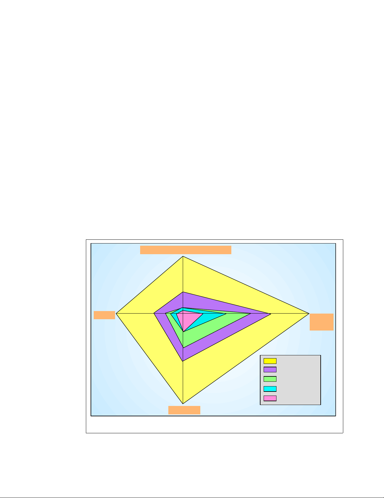
The chart in Figure 1-1 shows growth improvements along all axes. While some of the
previous generation of servers have grown more along one axis for a given family, later
families focus on the other axes. Now, with the z990, the balanced design achieves
improvement equally along all four axes.
System I/O Bandwidth
96 GBps
24 GBps
256 GB
Memory
External I/O or STI bandwidth only (Internal Coupling Channels and HiperSockets not included).
zSeries MCM internal bandwidth is 500 GB/sec. Memory bandwidth not included (not a system constraint) .
64 GB
16-way
32-way
CPUs
1.3 ns
zSeries z9XX
zSeries z900
Generation 6
Generation 5
Generation 4
0.83 ns
Cycle
Time
Figure 1-1 Balanced system design
2 IBM ^ zSeries 990 Technical Guide
Page 15
1.1 Introduction
The z990 further extends and integrates key platform characteristics: dynamic and flexible
partitioning, resource management in mixed and unpredictable workload environments,
availability, scalability, clustering, and systems management with emerging e-business on
demand application technologies (for example, WebSphere®, Java™, and Linux).
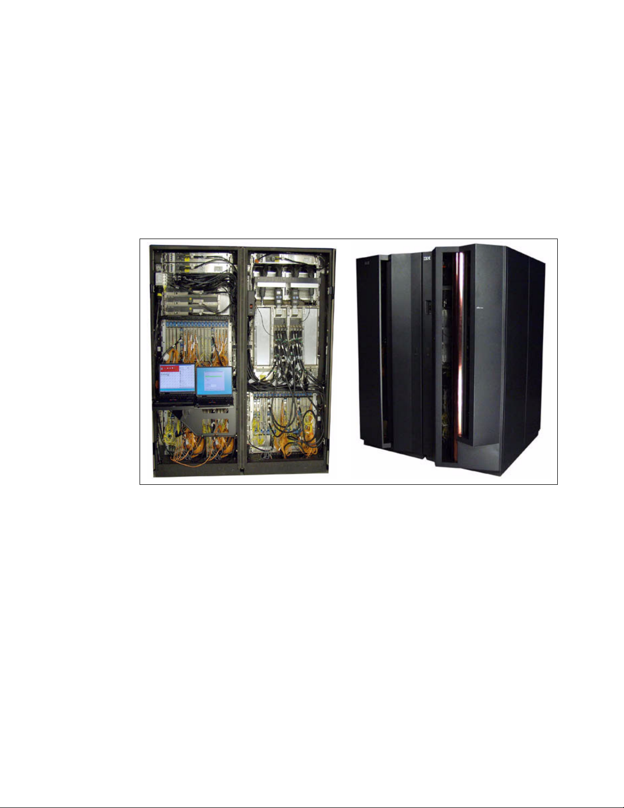
The zSeries 990 family provides a significant increase in performance over the previous
zSeries servers. The z990 introduces a different design from its predecessor, the zSeries
900. One noteworthy change is to the CEC cage, which is capable of housing up to four
books. This multi-book design provides enough Processor Units to improve total system
capacity by nearly three times over that provided by z900.
Figure 1-2 Introducing the z990 - internal and external view
The z990 introduced the superscalar microprocessor architecture. This design, and the
exploitation of the CMOS 9SG-SOI technology, improves the uniprocessor performance by
54% to 61%, compared to z900 Model 2C1. However, the true capacity increase of the
system is driven by the increased number of Processor Units per system: from 20 in the z900
to 48 Processor Units in the z990. The 48 Processor Units are packaged in four MCMs with
12 Processor Units each, plus up to 64 GB of memory and 12 STI links per book. All books
are connected via a super-fast redundant ring structure and can be individually upgraded.
The I/O infrastructure has been redesigned to handle the large increase in system
performance. The multiple Logical Channel Subsystems (LCSS) architecture on the z990
allows up to four LCSS, each with 256 channels. Channel types supported on the z990 are:
FICON Express
Coupling Links
OSA-Express
ESCON®
Chapter 1. zSeries 990 overview 3
Page 16

The following channel types, or channel cards, are not supported on the z990:
Parallel channels
4-port ESCON cards
OSA-2 cards
OSA-Express ATM cards
Pre-FICON Express cards
PCICC cards
The logical partitioning facility, PR/SM, provides the ability to configure and operate as many
as 30 logical partitions. PR/SM manages all the installed and enabled resources (processors
and memory) of the installed books as a single large SMP. Each logical partition has access
to physical resources (processors, memory, and I/O) in the whole system across multiple
books.
1.2 z990 models
The z990 has a machine type of 2084 and has four models: A08, B16, C24, and D32. The
model naming is representative of the book design of the z990, as it indicates the number of
books and the number of Processor Units available in the configuration. PUs are delivered in
single increments, orderable by feature code. A Processor Unit (PU) can be characterized as
a Central Processor (CP), Integrated Facility for Linux (IFL), Internal Coupling Facility (ICF),
zSeries Application Assist Processor (zAAP), or System Assist Processor (SAP).
The development of a multi-book system provides an opportunity for customers to increase
the capacity and/or requirements of the system in three areas:
You can add capacity by activating more CPs, IFLs, ICFs, or zAAPs on an existing book
concurrently.
You can add a new book concurrently and activate more CPs, IFLs, ICFs, or zAAPs.
You can add a new book to provide additional memory and/or STIs to support increasing
storage and/or I/O requirements. The ability to LICCC-enable more memory concurrently
to existing books is dependent on enough physical memory being present. Upgrades
requiring more memory than physically available are disruptive, requiring a planned
outage.
General rules
All models utilize a 12 PU MCM, of which eight are available for PU characterization. The
remaining four are reserved as two standard SAPs and two standard spares.
Model upgrades, from A08 to B16, from B16 to C24, or from C24 to D32, are achieved by
single book adds.
The model number designates the
use. Using feature codes, customers can order CPs, IFLs, ICFs, zAAPs, and optional SAPs,
unassigned CPs, and/or unassigned IFLs up to the maximum number of PUs for that model.
Therefore, an installation may order a model B16 with 13 CP features and three IFL features,
or a model B16 with only one CP feature.
maximum number of PUs available for an installation to
Unlike prior processor model names, which indicate the number of purchased CPs, z990
model names indicate the maximum number of Processor Units
not the actual number that have been ordered as CPs, IFLs, ICFs, zAAPs, or additional SAPs.
A software model notation is also used to indicate how many CPs are purchased and
software should be charged for. See “Software models” on page 63 for more information.
4 IBM ^ zSeries 990 Technical Guide
potentially orderable, and
Page 17
Model upgrade paths
With the exception of the z900 Model 100, any z900 model may be upgraded to a z990
model. With the advancement of Linux for S/390 and Linux on zSeries, customers may
choose to change the PU characterization of the server they are upgrading. In addition,
customers who are consolidating may not be increasing total capacity, and/or they may wish
to take advantage of the multiple Logical Channel Subsystems offered. z990-to-z990 model
upgrades and feature adds may be completed concurrently.
Model downgrades
There are no model downgrades offered. Customers may purchase unassigned CPs or IFLs
for future use. This avoids the placement of RPQ orders and subsequent sequential MES
activity, and paying software charges for capacity that is not in use.
Concurrent Processor Unit (PU) conversions
z990 servers support concurrent conversion between different PU types, providing flexibility
to meet changing business environments. Assigned CPs, unassigned CPs, assigned IFLs,
unassigned IFLs, and ICFs may be converted to assigned CPs, assigned IFLs or ICFs, or to
unassigned CPs or unassigned IFLs.
1.3 System functions and features
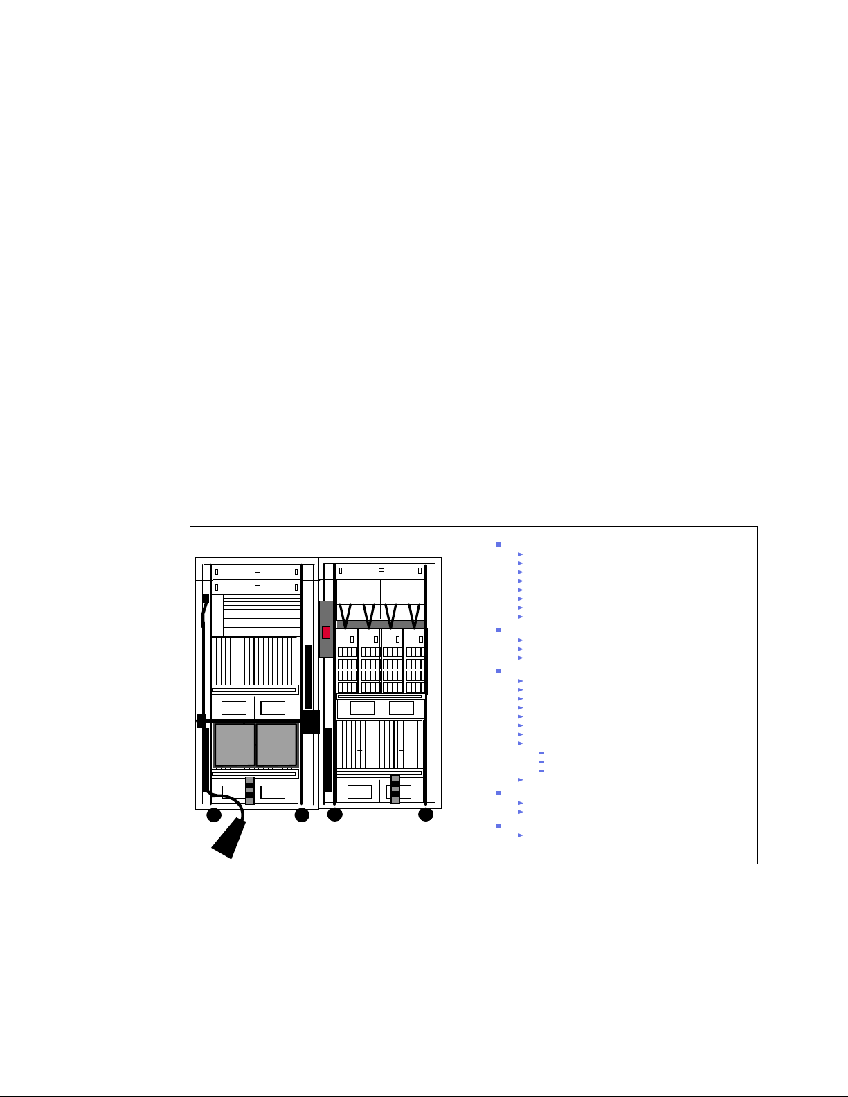
The 990 system offers the following functions and features, as shown in Figure 1-3.
Z frame
Figure 1-3 System overview
1.3.1 Processor
IBF
IBF
BPD
MDA MDA
Dual SEs
Cargo
Cargo
MDA MDA
A frame
IBF
MRU M RU
MDA MDAMDA MDA
MDA
MDA
Processor
4 flexible Models (A08, B16, C24 & D32)
64-bit Architecture
32 characterizable PUs, CMOS9G -SOI Technology
SuperScalar
Capacity Upgrade on Dem and including Mem ory and I/O
Hybrid Cooling (Air/Liquid)
Up to 30 Logical Partitions
Optional ETR feature
Memory
64 GB per Model, max system memory 256 GB
Card sizes 8, 16, 32 GB (2 cards per Book)
Bi-directional redundant Ring Structure
I/O
64-bit Architecture (42/48-bit I/O addressing in hardware)
Up to 48 x 2 GB/s Self-Timed Interconnects (STIs)
I/O cage with enhanced power
Up to 4 Logical Channel Subsystems (LCSS)
Up to 120 FICON Express™Channels
FCP SCSI over Fibre Channel
Up to 48 OSA-Express network connectors
Crypto
SSL
PCIXCC
No CHPID number required
Up to 16 HiperSockets
Parallel Sysplex technology
ICB-4 (2 GB /s), ICB-3, ICB-2, ISC- 3, IC
CF Duplexing
HMC
Alternate Service Element
IBM introduced the Processor Resource/Systems Manager™ (PR/SM) feature in February
1988, supporting a maximum of four logical partitions. In June 1992, IBM introduced support
for a maximum of 10 logical partitions and announced the Multiple Image Facility (MIF, also
known as EMIF), which allowed sharing of ESCON channels across logical partitions, and
since that time, has allowed sharing of more channels across logical partitions (such as
Chapter 1. zSeries 990 overview 5
Page 18

Coupling Links, FICON, and OSA). In June 1997, IBM announced increased support - up to
15 logical partitions on Generation 3 and Generation 4 servers.
The evolution continues and IBM is announcing support for 30 logical partitions. This support
is exclusive to z990 and z890 models.
MCM technology
The z990 12-PU MCM is smaller and more capable than the z900’s 20-PU MCM. It has
16 chips, compared to 35 for the z900. The total number of transistors is over 3 billion,
compared with approximately 2.5 billion for the z900. With this amazing technology
integration comes improvements in chip-to-substrate and substrate-to-board connections.
The z990 module uses a connection technology, Land Grid Arrays (LGA), pioneered by the
pSeries® in the p690 and the i890. LGA technology enables the z990 substrate, with only
53% of the surface area of the z900 20 PU MCM substrate, to have 23% more I/Os from the
logic package.
Both the z900 and z990 have 101 layers in the glass ceramic substrate. The z990's substrate
is thinner, shortening the paths that signals must travel to reach their destination (another chip
or exiting the MCM). Inside the low dielectric glass ceramic substrate is 0.4 km of internal
wiring that interconnects the 16 chips that are mounted on the top layer of the MCM. The
internal wiring provides power and signal paths into and out of the MCM.
The MCM on the z990 offers flexibility in enabling spare PUs via the Licensed Internal Code
Configuration Control (LIC-CC) to be used for a number of different functions. These are:
A Central Processor (CP)
A System Assist Processor (SAP)
An Internal Coupling Facility (ICF)
An Integrated Facility for Linux (IFL)
A zSeries Application Assist Processor (zAAP)
The number of CPs and SAPs assigned for particular general purpose models depends on
the configuration. The number of spare PUs is dependent on how many CPs, SAPs, ICFs,
zAAPs, and IFLs are present in a configuration.
1.3.2 Memory
The minimum system memory on any model is 16 GB. Memory size can be increased in 8 GB
increments to a maximum of 64 GB per book or 256 GB for the entire CPC. Each book has
two memory cards, which come in three physical size cards: 8 GB, 16 GB, and 32 GB.
The z990 continues to employ storage size selection by Licensed Internal Code introduced on
the G5 processors. Memory cards installed may have more usable memory than required to
fulfill the machine order. LICCC will determine how much memory is used from each card.
1.3.3 Self-Timed Interconnect (STI)
An STI is an interface to the Memory Bus Adaptor (MBA), used to gather and send data. 12
STIs per z990 physical book is supported. Each of these STIs has a bidirectional bandwidth
of 2 GBps. The maximum instantaneous bandwidth per book is 24 GBps.
1.3.4 Channel Subsystem (CSS)
A new Channel Subsystem (CSS) structure was introduced with z990 to “break the barrier” of
256 channels. With the introduction of the new system structure and all of its scalability
6 IBM ^ zSeries 990 Technical Guide
Page 19

benefits, it was essential that the Channel Subsystem also be scalable and allow “horizontal”
growth. This is facilitated by multiple Logical Channel Subsystems (LCSSs) on a single
zSeries server. The CSS has increased connectivity and is structured to provide the
following:
Four Logical Channel Subsystems (LCSS).
Each LCSS may have from one to 256 channels.
Each LCSS can be configured with 1 to 15 logical partitions.
Each LCSS supports 63K I/O devices.
Note: There is no change to the operating system maximums. One operating system
image continues to support a maximum of 256 channels, and has a maximum of 63K
subchannels available to it.
The I/O subsystem continues to be viewed as a single Input/Output Configuration Data Set
(IOCDS) across the entire system with multiple LCSS. Only one Hardware System Area
(HSA) is used for the multiple LCSSs.
A three-digit Physical Channel Identifier (PCHID) is being introduced to accommodate the
mapping of 1024 channels to four LCSSs, with 256 CHPIDs each. CHPIDs continue to exist
and will be associated with PCHIDs. An updated CHPID Mapping Tool (CMT) is being
introduced and the CHPID report from e-config is replaced by a PCHID report. The CHPID
Mapping Tool is available from Resource Link™ as a stand-alone PC-based program.
1.3.5 Physical Channel IDs (PCHIDs) and CHPID Mapping Tool
A z990 can have up to 1024 physical channels, or PCHIDs. In order for an operating system
to make use of that PCHID, it must be mapped to a CHPID within the IOCDs. Each CHPID is
uniquely defined with an LCSS and mapped to an installed PCHID. A PCHID is eligible for
mapping to any CHPID in any LCSS.
The z990 CHPID Mapping Tool (CMT) provides a method of customizing the CHPID
assignments for a z990 system to avoid attaching critical channel paths to single points of
failure. It should be used after the machine order is placed and before the system is delivered
for installation. The tool can also be used to remap CHPIDs after hardware upgrades that
increase the number of channels.
The tool maps the CHPIDs from an IOCP file to Physical Channel Identifiers (PCHIDs) that
are assigned to the I/O ports. The PCHID assignments are fixed and cannot be changed.
A list of PCHID assignments for each hardware configuration is provided in the PCHID Report
available when the z990 hardware is ordered. Unlike previous zSeries systems, there are no
default CHPID assignments. CHPIDs are assigned when the IOCP file is built. When
upgrading an existing zSeries configuration to z990, CHPIDs can be mapped by importing the
IOCP file into the z990 CHPID Mapping Tool.
1.3.6 Spanned channels
As part of the z990 LCSS, the Channel Subsystem is extended to provide the high-speed,
transparent sharing of some channel types in a manner that extends the MIF shared channel
function. Internal Channel types such as HiperSocket (IQD) and Internal Coupling Channels
(ICP) can be configured as “spanned” channels. External channels such as FICON channels,
OSA features, and External Coupling Links can be defined as spanned channels. Spanned
channels will allow the channel to be configured to multiple LCSSs, thus enabling them to be
shared by any/all of the configured logical partitions, regardless of the LCSS in which the
partition is configured.
Chapter 1. zSeries 990 overview 7
Page 20
Note: Spanned channels are not supported for ESCON channels, FICON conversion
channels (FCV), and Coupling Receiver links (CBR, CFR).
1.3.7 I/O connectivity
Here we discuss I/O connectivity.
I/O cage
Each book provides 12 STI links (48 STI maximum with four books) for I/O and coupling
connectivity, and for cryptographic feature cards. Each of these links can either be configured
for ICBs, or be connected to STI distribution cards in the I/O cage(s). The data rate for the STI
is 2 GBps.
Note: The z900 compatibility I/O cage is not supported on the z990.
The z990 I/O cage contains seven STI domains. Each domain has the capability of four I/O
slots. A subset of previous zSeries 900 I/O and cryptographic cards is supported by the I/O
cages in the z990.
Note: Parallel channels, OSA-2, OSA-Express ATM, pre-FICON Express channels, and
PCICC feature cards are not supported in the z990.
The installation of an I/O cage remains a disruptive MES, so the Plan Ahead feature remains
an important consideration when ordering a z990 system.
The z990 is a two-frame server. The z990 has a minimum of one CEC cage and one I/O cage
in the A frame. The Z frame can accommodate an additional two I/O cages, making a total of
three for the whole system. Figure 1-4 shows the layout of the frames and I/O cages.
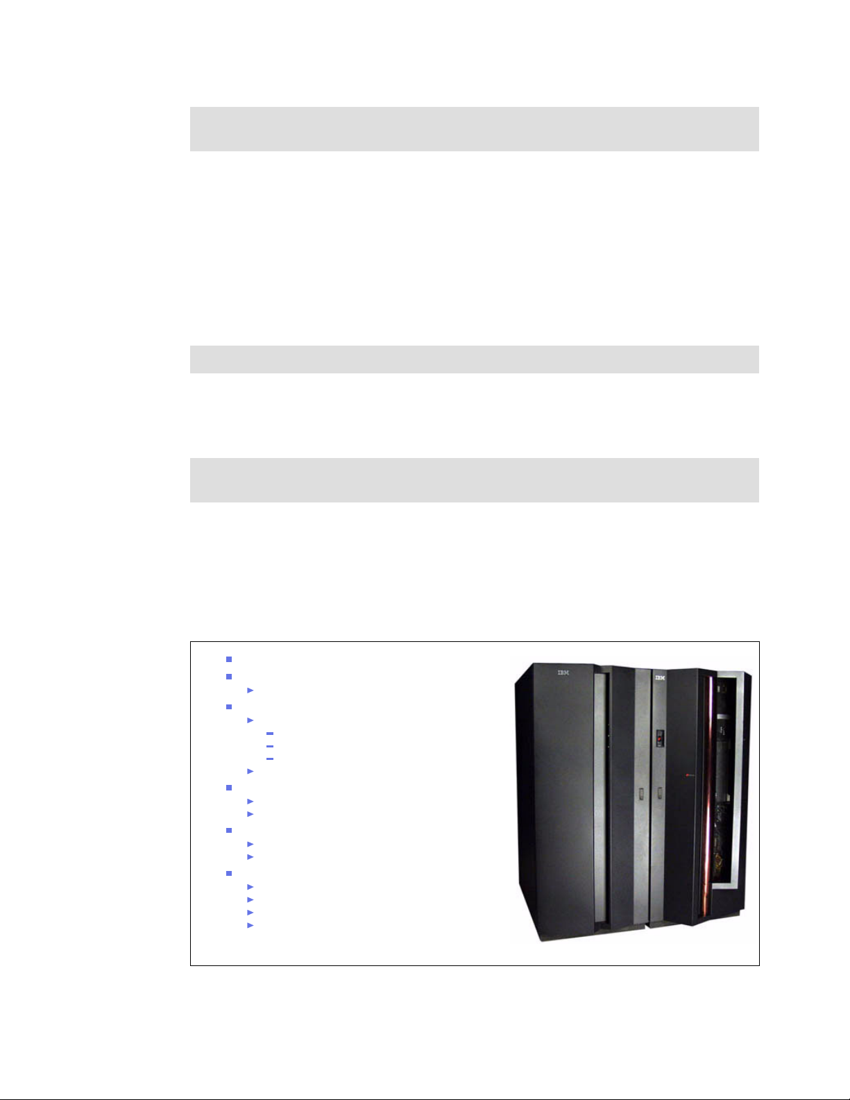
ESCON
z-Frame
A-Fr ame
FICON/FCP
FICON™Express
Networking
OSA-Express
Gigabit Ethernet
1000BASE-T Ethernet
Token Ring
HiperSockets
rd I/O
3
Cage
CEC
cage
Coupling Links
ISC-3
ICB-2, ICB-3, ICB-4, IC
Crypto
1
PCICA
PCIXCC
Not Supported
Parallel
OSA-E ATM and OSA-2
FICON (pre-FICON Express)
PCICC
2nd I/O
Cage
st I/O
Cage
Figure 1-4 I/O cage layout and supported cards and coupling links
8 IBM ^ zSeries 990 Technical Guide
Front View
Page 21

Up to 1024 ESCON channels
The high density ESCON feature (FC 2323) has 16 ports, of which 15 can be activated for
customer use. One port is always reserved as a spare, in the event of a failure of one of the
other ports.
This is not an orderable feature. The configuration tool will select the quantity of features
based upon the order quantity of ESCON FC2324 ports, distributing the ports across features
for high availability. After the first pair, ESCON FC2323 are installed in increments of one.
ESCON channels are available on a port basis in increments of four. The port quantity is
selected and LIC CC is shipped to activate the desired quantity of ports on the 16-port
ESCON FC2323. Each port utilizes a light emitting diode (LED) as the optical transceiver,
and supports use of a 62.5/125-micrometer multimode fiber optic cable terminated with a
small form factor, industry standard MT-RJ connector.
Up to 120 FICON Express channels
An increased number of FICON Express features per z990 leads the way in distinguishing
this server family, further setting it apart as enterprise class in terms of the number of
simultaneous I/O connections available for FICON Express features. z990 supports 60
FICON Express features to be plugged, providing a total of 120 available channels. This is a
25% growth over what was available on z900. These channels are available in long wave (LX)
and short wave (SX).
The FICON Express LX and SX channel cards have two ports. LX and SX ports are ordered
in increments of two. The maximum number of FICON Express cards is 60, installed in the
three I/O cages.
The same FICON Express channel card used for FICON channels is also used for FCP
channels. FCP channels are enabled on these cards as a microcode load with an FCP mode
of operation and CHPID type definition. As with FICON, FCP is available in long wavelength
(LX) and short wavelength (SX) operation, though the LX and SX cannot be intermixed on a
single card.
zSeries supports FCP channels, switches and FCP/SCSI devices with full fabric connectivity
under Linux on zSeries. Support for FCP devices means that z990 servers will be capable of
attaching to select FCP/SCSI devices, and may access these devices from Linux on zSeries.
This expanded attach ability means that customers have more choices for storage solutions,
or may have the ability to use existing storage devices, thus leveraging existing investments
and lowering total cost of ownership for their Linux implementation.
The 2 Gb capability on the FICON Express channel cards means that 2 Gb link speeds are
available for FCP channels as well.
The Fibre Channel Protocol (FCP) capability, supporting attachment to SCSI devices in Linux
environments, was made generally available in conjunction with IBM TotalStorage®
Enterprise Tape System 3590, IBM TotalStorage Enterprise Tape Drive 3592, and IBM
TotalStorage Enterprise Tape Library 3494. For VM guest mode, z/VM Version 4 Release 3 is
required to support Linux/FCP. When configured as a CHPID type FCP, FICON allows
concurrent patching of Licensed Internal Code without have to configure the channel off and
on.
Chapter 1. zSeries 990 overview 9
Page 22

The required Linux level for this function is SLES 8 from SUSE. This support allows a z990
system to access industry standard devices for Linux, using SCSI control block-based
Input/Output (I/O) devices. These industry standard devices utilize Fixed Block rather than
Extended Count Key Data (ECKD™) format. For more information, consult the IBM I/O
Connectivity Web page:
http://www.ibm.com/servers/eserver/zseries/connectivity/#fcp
FICON CTC function
Native FICON channels support CTC on the z990, z890, z900, and z800. G5 and G6 servers
can connect to a zSeries FICON CTC, as well. This FICON CTC connectivity will increase
bandwidth between G5, G6, z990, z890, z900, and z800 systems.
Because the FICON CTC function is included as part of the native FICON (FC) mode of
operation on zSeries, a FICON channel used for FICON CTC is not limited to intersystem
connectivity but will also support multiple device definitions. For example, ESCON channels
that are dedicated as CTC cannot communicate with any other device, whereas native FICON
(FC) channels are not dedicated to CTC only. Native mode can support both device and CTC
mode definition concurrently, allowing for greater connectivity flexibility.
FICON Cascaded Directors
Some time ago, IBM made the FICON Cascaded Director function generally available. This
means that a native FICON (FC) channel or a FICON CTC can connect a server to a device
or other server via two (same vendor) FICON Directors in between.
This type of cascaded support is important for disaster recovery and business continuity
solutions because it can provide high availability and extended distance connectivity, and
(particularly with the implementation of 2 Gb Inter Switch Links) has the potential for fiber
infrastructure cost savings by reducing the number of channels for interconnecting the two
sites.
The following directors and switches are supported:
CNT (INRANGE) FC/9000 64-port and 128-port models (IBM 2042)
McDATA Intrepid 6064 (IBM 2032)
McDATA Intrepid 6140 (IBM 2032)
McDATA Sphereon 4500 Fabric Switch (IBM 2031-224)
IBM TotalStorage SAN Switches 2109-F16, S16, and S08
IBM TotalStorage Director 2109-M12
FICON Cascaded Directors have the added value of ensuring high integrity connectivity.
Transmission data checking, link incidence reporting, and error checking are integral to the
FICON architecture, thus providing a true enterprise fabric.
For more information on Cascaded Directors, consult the I/O Connectivity Web page:
http://www.ibm.com/servers/eserver/zseries/connectivity/ficon_cascaded.html
OSA-Express
With the introduction of z990 and its increased processing capacity, and the availability of
multiple LCSSs, the Open Systems Adapter family of local area network (LAN) adapters is
also expanding by offering a maximum of 24 features per system (versus the maximum of 12
features per system on prior generations). The z990 can have 48 ports of LAN connectivity.
10 IBM ^ zSeries 990 Technical Guide
Page 23

You can choose any combination of OSA features: the OSA-Express Gigabit Ethernet LX
(FC1364), the OSA-Express Gigabit Ethernet SX (FC1365), the OSA-Express 1000BASE-T
Ethernet (FC1366), or OSA-Express Token Ring (FC2367). You can also carry forward your
current z900 OSA-Express features to z990, OSA-Express Gigabit Ethernet LX (FC 2364),
OSA-Express Gigabit Ethernet SX (FC 2365), OSA-Express Fast Ethernet (FC 2366), and
OSA-Express Token Ring (FC 2367).
Gigabit Ethernet
The OSA-Express GbE features (FC1364 and FC1365) have an LC Duplex connector type,
replacing the current SC Duplex connector. This conforms to the fiber optic connectors
currently in use for ISC-3 and the FICON Express features shipped after October 30, 2001.
1000BASE-T Ethernet
The z990 supports a copper Ethernet feature: 1000BASE-T Ethernet. This feature is offered
on new builds and replaces the current OSA-Express Fast Ethernet (FC 2366), which can be
brought forward to z990 on an upgrade from z900.
1000BASE-T Ethernet is capable of operating at 10, 100, or 1000 Mbps (1 Gbps) using the
same Category-5 copper cabling infrastructure that is utilized for Fast Ethernet. The Gigabit
over copper adapter allows a migration to gigabit speeds wherever there is a copper cabling
infrastructure instead of a fiber optic cabling infrastructure.
OSA-Express Integrated Console Controller (OSA-ICC)
An additional function of the OSA-Express 1000BASE-T Ethernet feature is its support as an
OSA-Express 100BASE-T Ethernet Integrated Console Controller. This function supports
TN3270E and non-SNA DFT 3270 emulation and means that 3270 emulation for console
session connections are integrated in the z990 via a port of the 1000BASE-T Ethernet
feature.
Checksum Offload for Linux and z/OS when in QDIO mode
A function introduced for the Linux on zSeries and z/OS environments, called checksum
offload, provides the capability of calculating the Transmission Control Protocol/User
Datagram Protocol (TCP/UDP) and Internet Protocol (IP) header checksums.
Checksum verifies the correctness of files. By moving the checksum calculations to a Gigabit
or 1000BASE-T Ethernet feature, host CPU cycles are reduced.
Improved performance can be realized by taking advantage of the checksum offload function
of the OSA-Express Gigabit Ethernet, and OSA-Express GbE or the 1000BASE-T Ethernet
(when operating at 1000 Mbps (1 Gbps)) features by offloading checksum processing to
OSA-Express (in QDIO mode, CHPID type OSD)) for most IPv4 packets. This support is
available with z/OS V1R5 and later as well as Linux on zSeries.
Token Ring
The OSA-Express Token Ring feature has two independent ports, each supporting
attachment to either a 4 Mbps, 16 Mbps, or 100 Mbps Token Ring Local Area Network (LAN).
The OSA-Express Token Ring feature supports autosensing as well as any of the following
settings: 4 Mbps half- or full-duplex, 16 Mbps half- or full-duplex, or 100 Mbps full-duplex.
Note: The demand for Token Ring on mainframe continues to decline. Migration from
Token Ring to an Ethernet infrastructure is recommended as part of long term planning for
Local Area Network support.
Chapter 1. zSeries 990 overview 11
Page 24

OSA-Express ATM
The OSA-Express Asynchronous Transfer Mode (ATM) features are not supported on z990.
They are not offered as a new build option and are not offered on an upgrade from z900. This
satisfies the Statement of General Direction in the hardware announcement dated April 30,
2002.
If ATM connectivity is still desired, a multiprotocol switch or router with the appropriate
network interface (for example, 1000BASE-T Ethernet, Gigabit Ethernet) can be used to
provide connectivity between the z990 and an ATM network.
OSA-2 FDDI
The OSA-2 Fiber Distributed Data Interface (FDDI) feature is not supported on z990. It is not
offered as a new build option and is not offered on an upgrade from z900. This satisfies the
Statement of General Direction in the hardware announcement dated October 4, 2001.
If FDDI connectivity is still desired, a multiprotocol switch or router with the appropriate
network interface (for example, 1000BASE-T Ethernet, Gigabit Ethernet) can be used to
provide connectivity between the z990 and a FDDI LAN.
Parallel channels and converters
Parallel channels are not supported on z990. Customers who wish to use parallel-attached
devices with z990 must obtain a parallel channel converter box such as the IBM 9034, which
may be available through IBM Global Services (IGS), or obtain a third-party parallel channel
converter box such as the Optica 34600 FXBT. In both cases, these are connected to an
ESCON channel.
For more information about Optica offerings, contact Optica directly:
http://www.opticatech.com/
1.3.8 Cryptographic
Here we discuss cryptographic functions and features.
CP Assist for cryptographic function
The zSeries cryptography is further advanced with the introduction of the Cryptographic
Assist Architecture implemented on every z990 PU. The z990 processor provides a set of
symmetric cryptographic functions, synchronously executed, which enormously enhance the
performance of the encrypt/decrypt function of SSL, Virtual Private Network (VPN), and data
storing applications that do not require FIPS 140-2 level 4 security. The on-processor crypto
functions run at z990 processor speed.
These cryptographic functions are implemented in every PU; the affinity problem of pre-z990
systems is eliminated. The Crypto Assist Architecture includes DES and T-DES data
en/decryption, MAC message authentication, and SHA-1 secure hashing. These functions
are directly available to application programs (zSeries Architecture instructions). SHA-1 is
always enabled, but other cryptographic functions are available only when the Crypto
enablement feature (FC 3863) is installed.
PCI Cryptographic Accelerator feature (PCICA)
The Peripheral Component Interconnect Cryptographic Accelerator (PCICA) feature has two
accelerator cards per feature and is an optional addition, along with the Peripheral
Component Interconnect X Cryptographic Coprocessor (PCIXCC) FC0868. The PCICA is a
very fast cryptographic processor designed to provide leading-edge performance of the
12 IBM ^ zSeries 990 Technical Guide
Page 25

complex RSA cryptographic operations used with the Secure Sockets layer (SSL) protocol
supporting e-business. The PCICA feature is designed specifically for maximum speed SSL
acceleration.
Each zSeries PCI Cryptographic Accelerator feature (PCICA) contains two accelerator cards
and can support up to 2100 SSL handshakes per second.
Note: To enable the function of the PCICA feature, the CP Assist feature (feature code
3863) must be installed.
PCI X-Cryptographic Coprocessor (PCIXCC) feature
The Peripheral Component Interconnect X Cryptographic Coprocessor (PCIXCC) feature has
one coprocessor and is an optional addition, containing support to satisfy high-end server
security requirements by providing full checking and fully programmable functions and User
Defined Extension (UDX) support.
The PCIXCC adapter is intended for applications demanding high security. The PCIXCC
feature is designed for the FIPS 140-2 Level 4 compliance rating for secure cryptographic
hardware.
Note: To enable the function of the PCIXCC feature, the CP Assist feature (feature code
3863) must be installed.
1.3.9 Parallel Sysplex support
Here we discuss Parallel Sysplex support.
ISC-3
A 4-port ISC-3 card structure is provided on the z900 family of processors. It consists of a
Mother Card with two Daughter Cards that have two ports each. Each Daughter Card is
capable of operating at 1 Gbps in compatibility mode (HiPerLink) or 2 gigabits/sec in peer
mode and up to 10 km. The mode is selected for each port via the CHPID type in the IOCDS.
InterSystem Coupling Facility-3 (ISC-3) channels provide the connectivity required for data
sharing between the Coupling Facility and the CPCs directly attached to it. ISC-3 channels
are point-to-point connections that require a unique channel definition at each end of the
channel. ISC-3 channels operating in peer mode provide connections between z990, z890,
and z900 general purpose models and z900-based Coupling Facility images. ISC-3 channels
operating in compatibility mode provide connections between z990 models and ISC HiperLink
channels on 9672 G5/G6 models.
ICB-2 (Integrated Cluster Bus 2)
The Integrated Cluster Bus-2 (ICB-2) link is a member of the family of Coupling Link options
available on z990. Like the ISC-3 link, it is used by coupled systems to pass information back
and forth over high speed links in a Parallel Sysplex environment. ICB-2 or ISC-3 links are
used to connect 9672 G5/G6 to z990 servers.
An STI-2 resides in the I/O cage and provides two output ports to support the ICB-2
connections. The STI-2 card converts the 2 GBps input into two 333 MBps ICBs. The ICB-2 is
defined in compatibility mode and the link speed is 333 MBps.
One feature is required for each end of the link. Ports are ordered in increments of one.
Chapter 1. zSeries 990 overview 13
Page 26

ICB-3 (Integrated Cluster Bus 3)
The Integrated Cluster Bus-3 (ICB-3) link is a member of the family of Coupling Link options
available on z990. Like the ISC-3 link, it is used by coupled systems to pass information back
and forth over high speed links in a Parallel Sysplex environment. ICB-3 or ISC-3 links are
used to connect z900, z800, or z890 servers (2064, 2066, or 2086) to z990 servers.
An STI-3 card resides in the I/O cage and provides two output ports to support the ICB-3
connections. The STI-3 card converts the 2 GBps input into two 1 GBps ICBs. The ICB-3 is
defined in peer mode and the link speed is 1 GBps.
One feature is required for each end of the link. Ports are ordered in increments of one.
ICB-4 (Integrated Cluster Bus 4)
The Integrated Cluster Bus-4 (ICB-4) link is a member of the family of Coupling Link options
available on z990. ICB-4 is a “native” connection used between z990 and or z890 processors.
An ICB-4 connection consists of one link that attaches directly to an STI port in the system,
does not require connectivity to a card in the I/O cage, and operates at 2 GBps. The ICB-4
works in peer mode and the link speed is 2 GBps.
One feature is required for each end of the link. Ports are ordered in increments of one.
Internal Coupling (IC)
The Internal Coupling-3 (IC) channel emulates the Coupling Facility functions in LIC between
images within a single system. No hardware is required; however, a minimum of two CHPID
numbers must be defined in the IOCDS for each connection.
System-Managed CF Structure Duplexing
System-Managed Coupling Facility (CF) Structure Duplexing provides a general purpose,
hardware-assisted, easy-to-exploit mechanism for duplexing CF structure data. This provides
a robust recovery mechanism for failures (such as loss of a single structure or CF or loss of
connectivity to a single CF) through rapid failover to the other structure instance of the duplex
pair.
The following three structure types can be duplexed using this architecture:
Cache structures
List structures
Locking structures
Support for these extensions is included in Coupling Facility Control Code (CFCC) Levels 11
12, and 13 and in z/OS V1.2, V1.3, V1.4, and V1.5 and later.
For those CF structures that support the use of System-Managed CF Structure Duplexing,
customers have the ability to dynamically enable or disable, selectively by structure, the use
of System-Managed CF Structure Duplexing.
Customers interested in deploying System-Managed CF Structure Duplexing in their test,
development, or production Parallel Sysplex will need to read the technical paper
System-Managed CF Structure Duplexing, GM13-0100 and analyze their Parallel Sysplex
environment to understand the performance and other considerations of using this function.
System-Managed CF Structure Duplexing, GM13-0100 is available at these Web sites:
http://www.ibm.com/server/eserver/zSeries/pso
http://www.ibm.com/servers/eserver/zSeries/library/techpapers/gm130103.html
14 IBM ^ zSeries 990 Technical Guide
Page 27

1.3.10 Intelligent Resource Director (IRD)
Exclusive to the IBM z/Architecture is Intelligent Resource Director (IRD), a function that
optimizes processor and channel resource utilization across logical partitions based on
workload priorities. IRD combines the strengths of the PR/SM, Parallel Sysplex clustering,
and z/OS Workload Manager.
Intelligent Resource Director uses the concept of an “LPAR cluster”, the subset of z/OS
systems in a Parallel Sysplex cluster that are running as logical partitions on the same z900
server. In a Parallel Sysplex environment, Workload Manager directs work to the appropriate
resources, based on business policy. With IRD, resources are directed to the priority work.
Together, Parallel Sysplex technology and IRD provide flexibility and responsiveness to
e-business workloads that are unrivaled in the industry.
IRD has three major functions: LPAR CPU Management, Dynamic Channel Path
Management, and Channel Subsystem Priority Queuing, which are explained in the following
sections.
Channel Subsystem Priority Queuing
Channel Subsystem Priority Queuing on the z900 allows priority queueing of I/O requests
within the Channel Subsystem, and the specification of relative priority among logical
partitions. WLM in goal mode sets priorities for a logical partition, and coordinates this activity
among clustered logical partitions.
Dynamic Channel Path Management
This feature enables customers to have channel paths that dynamically and automatically
move to those ESCON I/O devices that have a need for additional bandwidth due to high I/O
activity. The benefits are enhanced by the use of goal mode and clustered logical partitions.
LPAR CPU Management
Workload Manager (WLM) dynamically adjusts the number of logical processors within a
logical partition and the processor weight, based on the WLM policy. The ability to move the
CPU weights across an LPAR cluster provides processing power to where it is most needed,
based on WLM goal mode policy.
1.3.11 Hardware consoles
Here we discuss the Hardware Management Console and Support Element interface.
Hardware Management Console and Support Element interface
On z990 servers, the Hardware Management Console (HMC) provides the platform and user
interface that can control and monitor the status of the system via the two redundant Support
Elements installed in each z990.
The z990 server implements two fully redundant interfaces, known as the Power Service
Control Network (PSCN), between the two Support Elements and the CPC. Error detection
and automatic switchover between the two redundant Support Elements provides enhanced
reliability and availability.
1.3.12 Concurrent upgrades
The z990 servers have concurrent upgrade capability via the Capacity Upgrade on Demand
(CUoD) function. This function is also used by Customer Initiated Upgrades (CIUs) and by the
Capacity BackUp (CBU) feature implementation; more details follow.
Chapter 1. zSeries 990 overview 15
Page 28

Capacity Upgrade on Demand (CUoD)
Capacity Upgrade on Demand offers server upgrades via Licensed Internal Code (LIC)
enabling. CUoD can concurrently add processors (CPs, IFLs, ICFs, or zAAPs), and memory
to an existing configuration when no hardware changes are required, resulting in an upgraded
server. Also, I/O features can be added concurrently.
However, adequate planning is required. Proper models and memory card sizes must be
used, and the Plan Ahead feature with concurrent conditioning enablement is recommended
in order to ensure that all required infrastructure components are available.
Customer Initiated Upgrade (CIU)
Customer Initiated Upgrades are Web-based solutions for customers ordering and installing
upgrades via IBM Resource Link and the z990 Remote Support Facility (RSF). A CIU
requires a special contract and registration with IBM. The CIU uses the CUoD function to
allow concurrent upgrades for processors (CPs, IFLs, ICFs, and zAAPs), and memory,
resulting in an upgraded server.
As a CUoD, it also requires proper planning with respect to z990 model and memory card
sizes. CIU is
not available for I/O upgrades.
On/Off Capacity Upgrade on Demand (On/Off CoD)
On/Off Capacity on Demand (On/Off CoD) for z990 gives the customer the ability to
temporarily turn on unowned PUs available within the current model. This capability allows
customers to add capacity (CPs, IFLs, ICFs, and zAAPs) temporarily to meet peak workload
demands.
Note: The On/Off CoD capability can coexist with Capacity BackUp (CBU) enablement.
Both On/Off CoD and CBU LIC-CC can be installed on a z990 server, but the On/Off CoD
activation and CBU activation are mutually exclusive.
The customer has to accept contractual terms for On/Off CoD to use this capability; activation
of the additional capacity uses the CIU process. The usage is monitored and customer incurs
additional charges for both the hardware and software until the added capacity is deactivated.
Capacity BackUp (CBU)
Capacity BackUp (CBU) is a temporary upgrade for customers who have a requirement for a
robust disaster/recovery solution. It requires a special contract with IBM. CBU can
concurrently add CPs to an existing configuration when another customer’s servers are
experiencing unplanned outages.
Note: The CBU capability can coexist with On/Off CoD enablement. Both On/Off CoD and
CBU LIC-CC can be installed on a z990 server, but the On/Off CoD activation and CBU
activation are mutually exclusive.
The proper number of CBU features, one for each “backup” CP, must be ordered and
installed to restore the required capacity under disaster situations. The CBU activation can be
tested for disaster/recovery procedures validation and testing.
Since this is a temporary upgrade, the original configuration must be restored after a test or
disaster recovery situation via a concurrent CBU deactivation.
16 IBM ^ zSeries 990 Technical Guide
Page 29
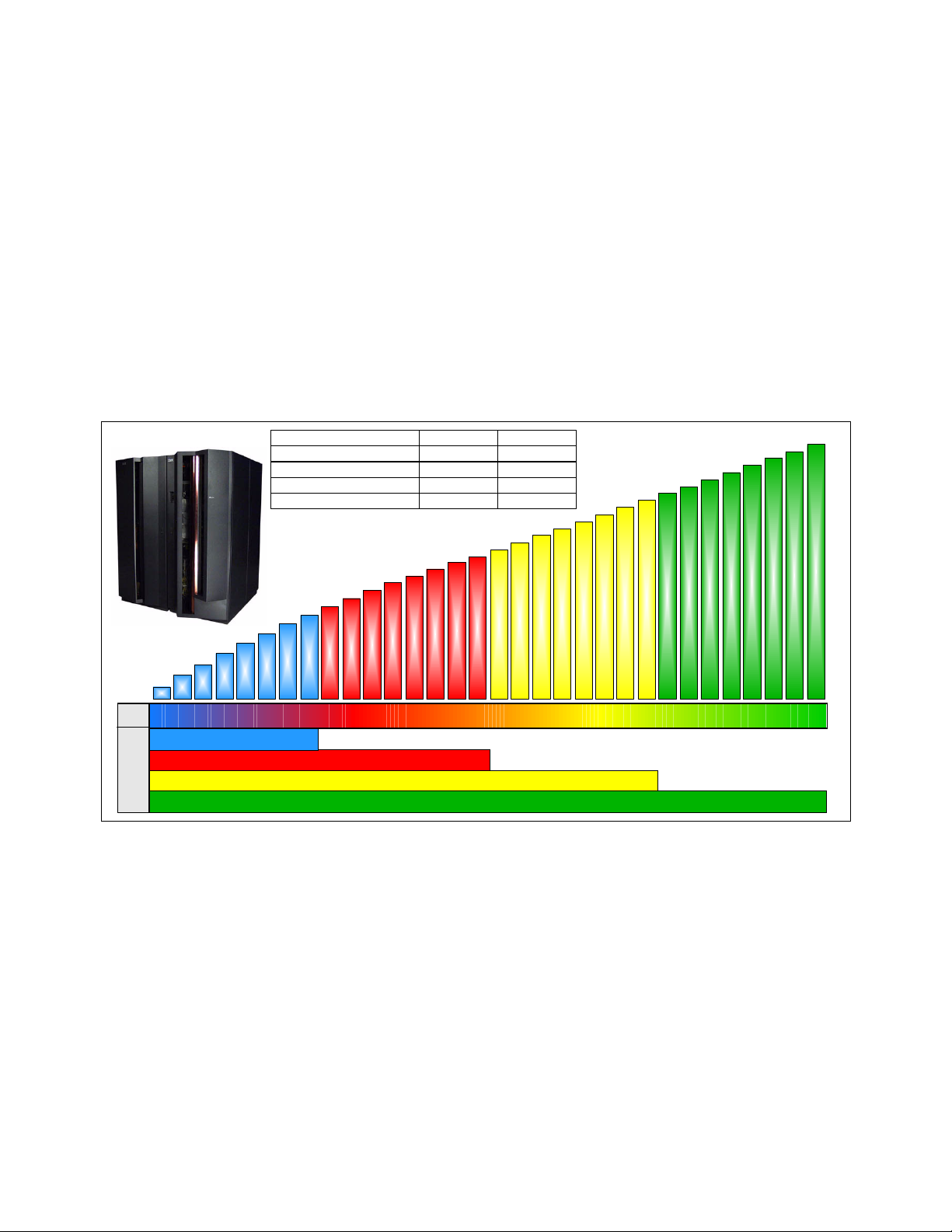
1.3.13 Performance
The IBM Large Systems Performance Reference method provides comprehensive
z/Architecture processor capacity data for different configurations of central processing units
across a wide variety of system control program and workload environments. For zSeries
z990, z/Architecture processor capacity is defined with a 3xx notation, where xx is the number
of installed Central Processor (CP) units.
The actual throughput that any user will experience will vary, depending upon considerations
such as the amount of multiprogramming in the user's job stream, the I/O configuration, and
the workload processed. Therefore, no assurance can be given that an individual user will
achieve throughput improvements equivalent to the performance ratios shown in Figure 1-5.
For more detailed performance information, consult the Large Systems Performance
Reference (LSPR), found at:
http://www.ibm.com/servers/eserver/zseries/lspr
Number of z990 CPs Base Ratio
1 CP z900-2C1 1.54 - 1.61
8 CPs z900-2C8 1.52 - 1.56
16 CPs z900-216 1.51 - 1.55
32 CPS z900-216 2.46 - 2.98
*
S/W
301 302 303 304 305 306 307 308 309 310 311 312 313 314 315 316 317 318 319 320 321 322 323 324 325 326 327 328 329 330 331 332
Model
Model A08
Model B16
Model C24
Model D32
Figure 1-5 Performance comparison, SW models, and HW models
MSU values for all z990 software models are found at:
http://www.ibm.com/servers/eserver/zseries/library/swpriceinfo
1.3.14 Reliability, Availability, and Serviceability (RAS)
The z990 RAS strategy is a building-block approach developed to meet the customer's
stringent requirements of achieving Continuous Reliable Operation (CRO). Those building
blocks are: Error Prevention, Error Detection, Recovery, Problem Determination, Service
Structure, Change Management, and Measurement and Analysis.
The initial focus is on preventing failures from occurring in the first place. This is usually
accomplished by using “Hi-Rel” (highest reliability) components from our technology
suppliers, using screening, sorting, burn-in, run-in, and by taking advantage of technology
integration. For Licensed Internal Code (LIC) and hardware design, failures are eliminated
* S/W Model refers to number
of installed CPs. Reported by
STSI instruction. Model 300
does not have any CPs.
Chapter 1. zSeries 990 overview 17
Page 30
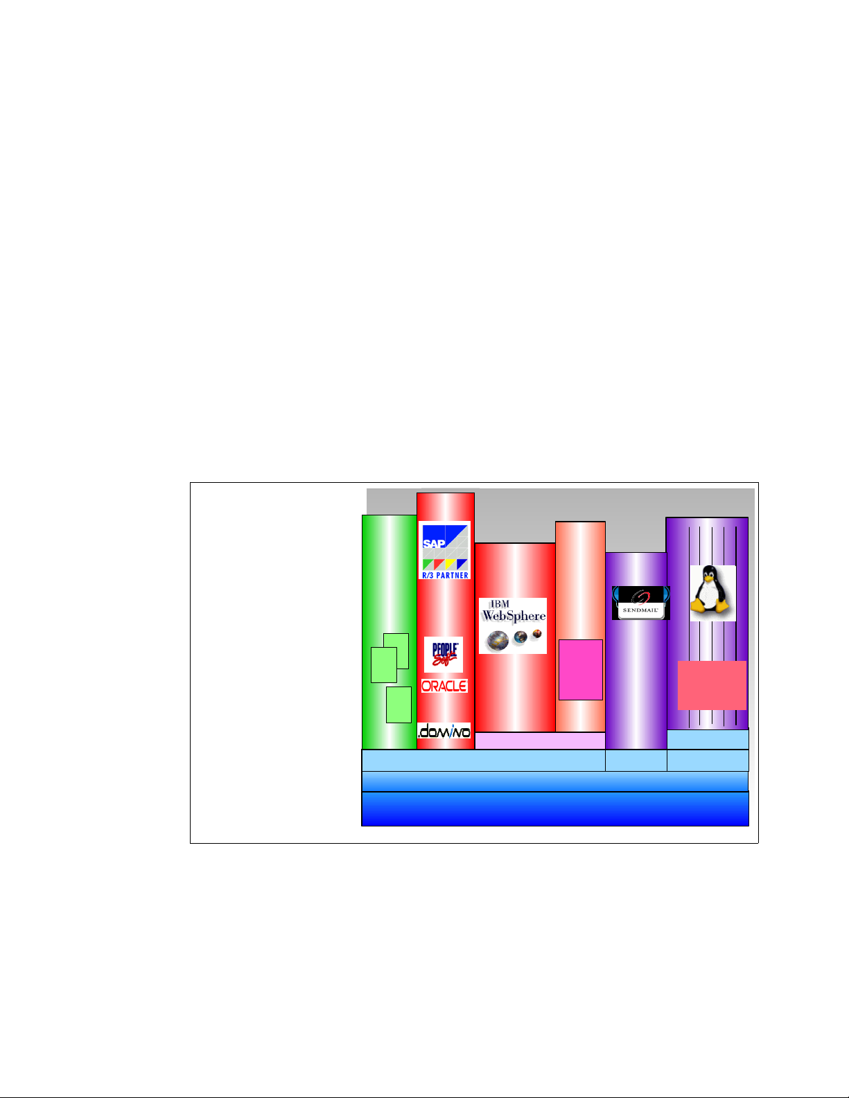
through rigorous design rules, design walk-throughs, peer reviews,
element/subsystem/system simulation, and extensive engineering and manufacturing testing.
The z990 RAS strategy is focused on a recovery design that is necessary to mask errors and
make them “transparent” to customer operations. There is an extensive hardware recovery
design implemented to be able to detect and correct array faults. In cases where total
transparency cannot be achieved, the capability exists for the customer to restart the server
with the maximum possible capacity.
1.3.15 Software
By supporting the Application Framework for e-business and Linux on zSeries, IBM provides
organizations with the choices and flexibility needed to develop a robust infrastructure that
provides the end-to-end qualities of service, speed of innovation, and affordability required for
successful e-business.
It also enables a higher degree of integration among the three classes of workload—data
transaction applications, Web applications and special function applications—that are the
basis of providing a seamless business transaction over the Web (see Figure 1-6).
The result is an infrastructure that supports a more rapid move into advanced e-business,
and a better chance of recognizing a lasting competitive advantage.
ERP
Trans-
action
Busin ess
appl.
The z990 Generation:
Trans-
action
Appl.+DB
"A heterogeneous software
model on
a homogeneous
hardware
platform"
IMS
CICS
DL/ I
DB2
Java
&
EJB
Siebel
WebSphere
e-commerce
JVM
z/OS
PR/SM LPAR (up to 30 logical partitions)
Appl *
Linux
Appl
Linux
Consoli date
Cluster/Parallel
File/Disk/Print
Linux
z/VM
zSeries Platform
Figure 1-6 z990, the versatile server
Traditional database/transaction workloads
z/OS is well positioned as the deployment platform for e-business data transaction
workloads. The traditional S/390 strengths—scalability, high availability, low total cost of
ownership, and robust security—are all necessary elements for a company seeking to create
the kind of flexible computing infrastructure required for enterprise-wide e-business solutions.
In addition, batch workloads, which never go away, even in an e-business environment, are a
strength for z/OS, particularly with its ability to run concurrent batch jobs with online and Web
18 IBM ^ zSeries 990 Technical Guide
Page 31

workloads; and batch jobs get resources as they are available. The strength of zSeries I/O
subsystem and I/O balancing capabilities are also key reasons for this platform’s excellent
support of batch workloads.
UNIX® System Services
UNIX System Services include shell functions, numerous utilities, and UNIX file systems.
Perhaps most significantly, what distinguished z/OS UNIX from other variants is that the
UNIX services were integrated into the z/OS base, not added as middleware or shipped as a
separate S/390 operating system. As a result, not only can UNIX applications be written for
zSeries, but they can also take advantage of z/OS facilities and zSeries hardware to obtain
true enterprise server qualities of service.
The importance of UNIX System Services is growing because most new applications and
middleware build upon them.
zSeries File System (zFS)
To meet the changing needs of new workloads, a different file system is available with
OS/390® R10 and beyond. This file system is complementary to the existing Hierarchical File
System (HFS), but provides enhanced performance and easier management for many
different file usage patterns often encountered with new workloads.
Linux on zSeries (and Linux for S/390)
Linux on zSeries offers a number of advantages compared to other platforms. First, it puts the
Linux applications close to the enterprise data and applications, thus reducing the chance for
bottlenecks. And since a Linux application runs in its own partition, with its own dedicated
resources, it does not impact the availability or security of the rest of the system.
A second advantage is the extremely reliable zSeries hardware, which can support up to 15
logical partitions on z900/z800 and up to 30 Linux logical partitions on z990—and thousands
of Linux images if Linux is run as a guest operating system under z/VM. Consolidation of
multiple Linux images on a single server can greatly simplify systems management.
With the large number of applications available in the open source community, many
customers will find Linux gives them a relatively low-cost way to deliver and integrate new
applications quickly. For others, Internet enablement may be quicker and easier when they
extend existing applications. Either way, zSeries support for the Application Framework for
e-business and Linux gives that choice and flexibility.
The choice of application source depends on a number of factors, including the source, the
required qualities of service, and the time allowed for development.
1.3.16 Software support
Here we discuss software support.
Compatibility and exploitation
Generally speaking, software support for the z990 comes in two steps: Compatibility support
and Exploitation support. However, there are variations specific to each operating system.
Compatibility support provides no additional functionality over and above a z900 or z800.
Compatibility only provides PTFs that allow the operating system to run on z990 or coexist in
a sysplex with z990.
Exploitation support provides the operating systems with the ability to take advantage of
greater than 15 logical partitions and multiple Logical Channel Subsystems (LCSS).
Chapter 1. zSeries 990 overview 19
Page 32

OS/390 and z/OS
OS/390 R10 and z/OS 1.2 to z/OS 1.5 and later all provide Compatibility support. In addition,
z/OS 1.4, and z/OS 1.5 or later will have Exploitation support for up to 30 logical partitions
and four LCSSs. OS/390 supports both 31-bit and 64-bit modes, while z/OS 1.2 to z/OS 1.4
have the bimodal migration accommodation available for fallback to 31-bit mode for a period
of up to 6 months.
Exploitation support can be installed on any z/OS 1.4 system, regardless of the hardware it is
running on, but obviously uses functionality as provided by that hardware. The Exploitation
support is include on z/OS 1.5 and later releases.
When z/OS or OS/390 has only Compatibility support applied, it is limited to running in
LCSS0 and may not have an LPAR ID greater than 'F'. In a z/OS only environment, if z/OS
does not have exploitation support, then it is limited to only 15 active logical partitions and up
to 256 CHPIDs. More partitions may be defined and may be physically installed, but they
cannot be used.
With Exploitation support on z/OS 1.4 or later, it is possible to fully exploit the z990
capabilities. It is possible to define up to 4 LCSS with up to 256 CHPIDs in each. Up to 30
logical partitions may be defined across the 4 LCSS. z/OS 1.5 has Exploitation support
delivered as part of the base function, but does not support 31-bit mode on z990.
Note: z/OS 1.1 is not supported on z990 or on any zSeries server participating in a
sysplex that includes a z990 server.
Linux
Linux for S/390 is available in 31-bit mode and will support Exploitation mode. Linux on
zSeries is available in 64-bit mode and will support Exploitation mode.
z/VM
All versions of z/VM support both 31-bit and 64-bit mode.
z/VM 4.4 and z/VM 5.1 and later are capable of exploiting up to 30 logical partitions and up to
four LCSSs. VM/ESA® is not supported on z990.
z/VSE
z/VSE Version 3.1 supports 31-bit mode only and Exploitation mode.
VSE/ESA™
VSE/ESA Versions 2.6 and 2.7 will support z990 with the appropriate maintenance.
TPF
TPF V4R1 is supported in 31-bit mode with Compatibility. TPF does not provide Exploitation
support.
Software pricing
The z990 product line qualifies for the same software pricing structure and software terms
and conditions that are currently available for the z900 and zSeries servers. Workload
License Charge (WLC) pricing is available when z/OS is running on the z990 server and all
other qualifying terms and conditions for WLC are met. WLC pricing is enhanced on the
variable charge products to provide greater granularity on z900 and z990 through lowering
the base charge from 45 MSUs to 3 MSUs.
20 IBM ^ zSeries 990 Technical Guide
Page 33

Parallel Sysplex License Charges (PSLC) apply for OS/390 software products and may apply
with the PSLC price option if the customer elects PSLC pricing. When servers currently
priced under the PSLC structure are upgraded to a z990 server, the customer may elect to
continue using PSLC pricing. However, if the z990 server is an upgrade from a z900 server
that has already converted to WLC pricing, the products running on the upgraded server must
be charged under the WLC structure.
VM and VSE products running on z990 servers qualify for the same pricing structures
currently available for other z900 servers. The Extended License Charge (ELC) applies for
servers over 80 MSUs. The Graduated Monthly License Charge (GMLC) applies for servers
under 80 MSUs. Customers who select WLC pricing for the z/OS environment must license
VM and VSE products with the Flat Workload License Charge (FWLC). z/VM Version 4
License, and Subscription and Support (S&S) charges, are priced per processor based on
terms and conditions.
Software charging for z990 will be based on the number of active CPs, except when
customers qualify, and elect WLC sub-capacity pricing. The z990 software MSU values are
determined when the order is placed; software charging is based on the full capacity of the
selected model. Full capacity is determined by the number of active CPs within the model.
The MSU performance ratings for the z990 server are available on the Web:
http://www.ibm.com/servers/eserver/zseries/library/swpriceinfo
1.3.17 Summary
On a physical resource level, z990 is a S/390 architecture server with a maximum of 48 PUs
and 256 GB of main memory structured in a four-book configuration. The books are
interconnected by a high speed memory coherence ring, thus building a large and very
efficient SMP. The I/O adapters are housed in three I/O cages, and provide a maximum of
1024 (maximum 256 per LCSS) channel ports.
The z900 to z990 is a “Frame Roll” MES. The z990 A and Z frames are shorter and deeper
than the z900's frames, actually taking up less space than the z900. The z900 I/O cards,
16-port ESCON, FICON Express, PCICA, and OSA Express will move to different I/O slots in
the new z990 system I/O cages.
PR/SM handles these physical resources as one contiguous space and provides, on a logical
level, up to 30 logical partitions and up to four Logical Channel Subsystems with 256 channel
paths each. Thus, a large and scalable physical resource pool is generated, managed by
PR/SM in a highly efficient way, taking advantage of LPAR clustering.
Dynamic CHPID management and I/O priority queuing were introduced with z900. These
capabilities are extended to support Linux (for S/390 and on zSeries) partitions with the same
efficiency. Since the maximum number of supported logical PUs within a partition is 24 (z/OS
V1.6, and z/VM V5.1 plans to have support for up to 24 processors in a single LPAR), multiple
copies of operating systems (z/OS and Linux) run “side-by-side” on the same hardware
platform. z990 also continues to support the latest Ethernet technology, to provide the highest
bandwidth connections to external servers.
Chapter 1. zSeries 990 overview 21
Page 34

22 IBM ^ zSeries 990 Technical Guide
Page 35

Chapter 2. System structure and design
This chapter introduces the IBM ^ zSeries 990 system structure. Significant functions
and features are described, along with their characteristics and options.
The goal is to explain how the z990 is structured, what its main components are, and how
these components interconnect from a physical and logical point of view. This information is
useful for planning purposes and will help you define the configuration that best fits your
requirements.
2
The following topics are included:
2.1, “System structure” on page 24
2.2, “System design” on page 38
© Copyright IBM Corp. 2003, 2004. All rights reserved. 23
Page 36

2.1 System structure
The z990 structure and design are the result of the continuous evolution of S/390 and zSeries
since CMOS servers were introduced in 1994. The structure and design have been
continuously improved, adding more capacity, performance, functionality, and connectivity.
The objective of z990 system structure and design is to offer a flexible infrastructure to
accommodate a wide range of operating systems and applications, whether they be
traditional or emerging e-business applications based on WebSphere, Java, and Linux, for
integration and deployment in heterogeneous business solutions.
For that purpose, the z990 introduces a superscalar microprocessor architecture, improving
uniprocessor performance, and providing an increase in the number of usable processors per
system. In order to keep a balanced system, the I/O bandwidth and available memory sizes
have been increased accordingly.
2.1.1 Book concept
The z990 Central Processor Complex (CPC) introduces a packaging concept based on
books. A book contains processors (PUs), memory, and connectors to I/O cages and ICB-4
links. Books are located in the CEC cage in Frame A. A z990 server (CPC) has at least one
book, but may have up to four books installed.
A book and its components is shown in Figure 2-1. Each book contains:
12 Processor Units (PUs). The PUs reside on microprocessor chips located on a
Multi-Chip Module (MCM).
16 GB to 64 GB physical memory. There are always two memory cards, each containing
8, 16, or 32 GB.
Three Memory Bus Adapters (MBAs), supporting up to 12 Self-Timed Interconnects
(STIs) to the I/O cages and/or ICB-4 channels.
MCM
STI Slots
Mem ory cards
Figure 2-1 Book structure and components
Up to four books can reside in the CEC cage. Books plug into cards, which plug into slots of
the CEC cage board.
24 IBM ^ zSeries 990 Technical Guide
Page 37

Power
Each book get its power from two Distributed Converter Assemblies (DCA) that reside on the
opposite side of the CEC board. The DCAs provide the required power for the book. Each
book is supported by two DCAs. The N+1 power supply design means that there is more DCA
capacity than is required for the book. If one DCA fails, the power requirement for a book can
still be satisfied from the remaining DCA. The DCAs can be concurrently maintained, which
means that replacement of one DCA can be done without taking the book down.
Between two sets of DCAs you find the location of the oscillator cards (OSC) and the optional
external time reference cards (ETR). If installed, there are two ETR ports to which an optional
Sysplex Timer® can be connected. Seen from the top, the packaging of a four-book system
appears as shown (schematically) in Figure 2-2.
Book3
Book0
Book1
Book2
Memory Cards
Memory Cards
Memory Cards
Memory Cards
MCM
MCM
MCM
MCM
DCA30
DCA31
DCA00
DCA01
DCA01
2xOSC 00/01 2xETR 00/01
DCA10
DCA11
DCA20
DCA21
Figure 2-2 Book and power packaging (top view)
Located within each book is a card on which the Memory Bus Adapters (MBAs) are located.
The card has three MBAs, each driving four STIs (see Figure 2-8 on page 32).
Figure 2-2 also illustrates the order of book installation:
In a one-book model, only book 0 is present.
A two-book model has books 0 and 1.
A three-book model has books 0, 1, and 2.
A four-book model has books 0, 1, 2, and 3.
Book installation to up to four books can be concurrent.
Cooling
The z990 is an air-cooled system assisted by refrigeration. Refrigeration is provided by a
closed-loop liquid cooling subsystem. The entire cooling subsystem has a modular
construction. Its components and functions are found throughout the cages, and are made up
of three subsystems:
1. The Modular Refrigeration Units (MRU)
– One or two MRUs (MRU0 and MRU1), located in the front of the A-cage above the
books, provide refrigeration to the content of the books together with Motor Drive
Assemblies in (MDAs) in the rear.
– A one-book system has MRU0 installed. Upgrading to a two-book system causes
MRU1 to be installed, providing all refrigeration needs for a four-book system.
Concurrent repair of an MRU is possible by taking advantage of the hybrid cooling
implementation described in the next section.
Chapter 2. System structure and design 25
Page 38

2. The Motor Scroll Assembly (MSA)
3. The Motor Drive Assembly (MDA)
– MDAs are found throughout the frames to provide air cooling where required. They are
located at the bottom front of each cage, and in between the CEC cage and I/O cage,
one in combination with the MSAs.
Hybrid cooling system
The z990 has a hybrid cooling system that is a breakthrough in lowering power consumption.
Normal cooling is provided by one or two MRUs connected to the heat sinks of all MCMs in all
books.
If one of the MRUs fails, backup MSAs are switched in to compensate for the lost refrigeration
capability with additional air cooling. At the same time, the oscillator card will be set to a
slower cycle time, slowing the system down by up to 8% of its maximum capacity, to allow the
degraded cooling capacity to maintain the proper temperature range. Running at a slower
cycle time, the MCMs will produce less heat. The slowdown process is done in steps, based
on the temperature in the books.
Figure 2-3 shows the refrigeration scope of MRU0 and MRU1.
MRU 0 MRU 1
Figure 2-3 MRU scope
2.1.2 Models
The z990 has four orderable models. The model numbers are directly related to the number of
books in the system and the maximum number of PUs that can be characterized by the
installation. For customer use, PUs can be characterized as CPs, IFLs, ICFs, zAAPs, or if
need be, additional SAPs.
The IBM 2084 model A08 has one book (A) with 12 PUs, of which eight can be
The IBM 2084 model B16 has two books (B) with 12 PUs in each book for a total of 24
The IBM 2084 model C24 has three books (C) with 12 PUs in each book for a total of 36
Book 0Book 3 Book 1 Book 2
characterized by the customer. The four remaining PUs are two system assist processors
(SAPs) and two spares.
PUs, of which 16 can be characterized by the customer. The four remaining PUs are four
system assist processors (SAPs) and four spares, two of each in each book.
PUs, of which 24 can be characterized by the customer. The remaining PUs are six
system assist processors (SAPs) and six spares, two of each in each book.
26 IBM ^ zSeries 990 Technical Guide
Page 39

The IBM 2084 model D32 has four books (D) with 12 PUs in each book for a total of 48
The last two digits of the model number reflect the maximum number of PUs that can be
characterized for installation use. The PUs can be characterized as CPs, IFLs, ICFs, zAAPs
or additional SAPs. The characters A, B, C, and D in the model number reflect the number of
books installed.
Whether one, two, three, or four books are present, to the user, all books together appear as
one Symmetric Multi Processor (SMP) with a certain number CPs, IFL, ICFs, and zAAPs a
certain amount of memory, and bandwidth to drive the I/O channels and devices. The
packaging is designed to scale to a 32-PU Symmetric Multi-Processor (SMP) server in four
books.
2.1.3 Memory
Maximum physical memory sizes are directly related to the number of books in the system.
Each book may contain a maximum of 64 GB of physical memory. The amount of memory on
each of the two memory cards in a book must be the same. The memory sizes in each book
do not have to be similar; different books may contain different amounts of memory. The
minimum orderable amount of memory is 16 GB, system-wide.
A one-book system (IBM 2084-A08) may contain 16 GB, 32 GB, or 64 GB of physical
PUs, of which 32 can be characterized by the customer. The remaining PUs are eight
system assist processors (SAPs) and eight spares, two of each in each book.
memory. Memory is orderable in 8 GB increments for customer use.
A two-book system (IBM 2084-B16) may contain up to a maximum of 128 GB of physical
memory. For all memory card distribution variations in newly built two-book systems, refer
to Table 2-1 on page 28. Memory is orderable in 8 GB increments for customer use.
A three-book system (IBM 2084-C24) may contain up to a maximum of 192 GB of physical
memory. For some memory card distribution variation in a newly built three-book system,
refer to Table 2-1 on page 28. Memory is orderable in 8 GB increments for customer use.
A four-book system (IBM 2084-D32) may contain up to a maximum of 256 GB of physical
memory. For some memory card distribution variation in a newly built four-book system,
refer to Table 2-1 on page 28. Memory is orderable in 8 GB increments for customer use.
The system physical memory is the sum of all book memories. Not all books need to contain
the same amount of memory, and not all installed memory is necessarily configured for use.
Memory sizes
The minimum orderable amount of usable memory for all models is 16 GB. Memory upgrades
are available in 8 GB increments:
IBM 2084 Model A08, from 16 to 64 GB
IBM 2084 Model B16, from 16 to 128 GB
IBM 2084 Model C24, from 16 to 192 GB
IBM 2084 Model D32, from 16 to 256 GB
Physically, the memory cards are organized as follows:
Each book always contains two memory cards. A memory card can come in three sizes:
–8 GB
– 16 GB
– 32 GB
Within a given book, the card sizes must be equal, but all books do not necessarily need to
have the same amount of physical memory installed.
Chapter 2. System structure and design 27
Page 40

A book may have more memory installed than enabled. The excess amount of memory
can be installed by a Licensed Internal Code code load (sometimes called “dial-a-Gig”),
when required by the installation.
On initial installation, the amount of physical memory in a given model is nearest to the
smallest possible size.
Memory upgrades are satisfied from already installed unused memory capacity until
exhausted. When no more unused memory is available from the installed memory cards,
cards have to be upgraded to a higher capacity, or the addition of a book with additional
memory is necessary.
Table 2-1 shows examples of memory configurations (not all possible combinations are
shown). It shows that an IBM 2084 model A08 may have 16 GB of usable memory out of a
minimum of 16 GB physically installed, and that an IBM 2084 model D32, though unlikely,
may have 16 GB of usable memory out of a minimum of 64 GB physical memory.
Table 2-1 New build 2084 physical memory card distribution
Available
Capacity
IBM 2084-A08
Physical Cards
IBM 2084-B16
Physical Cards
IBM 2084-C24
Physical Cards
IBM 2084-D32
Physical Cards
16 GB 2 x 8 GB Book1: 2 x 8 GB
Book2: 2 x 8 GB
24 GB 2 x 16 GB Book1: 2 x 8 GB
Book2: 2 x 8 GB
48 GB 2 x 32 GB Book1: 2 x 16 GB
Book2: 2 x 8 GB
64 GB 2 x 32 GB Book1: 2 x 16 GB
Book2: 2 x 16 GB
80 GB n/a Book1: 2 x 32 GB
Book2: 2 x 8 GB
96 GB n/a Book1: 2 x 32 GB
Book2: 2 x 16 GB
Book1: 2 x 8 GB
Book2: 2 x 8 GB
Book3: 2 x 8 GB
Book1: 2 x 8 GB
Book2: 2 x 8 GB
Book3: 2 x 8 GB
Book1: 2 x 8 GB
Book2: 2 x 8 GB
Book3: 2 x 8 GB
Book1: 2 x 16 GB
Book2: 2 x 8 GB
Book3: 2 x 8 GB
Book1: 2 x 16 GB
Book2: 2 x 16 GB
Book3: 2 x 8 GB
Book1: 2 x 16 GB
Book2: 2 x 16 GB
Book3: 2 x 16 GB
Book1: 2 x 8 GB
Book2: 2 x 8 GB
Book3: 2 x 8 GB
Book4: 2 x 8 GB
Book1: 2 x 8 GB
Book2: 2 x 8 GB
Book3: 2 x 8 GB
Book4: 2 x 8 GB
Book1: 2 x 8 GB
Book2: 2 x 8 GB
Book3: 2 x 8 GB
Book4: 2 x 8 GB
Book1: 2 x 8 GB
Book2: 2 x 8 GB
Book3: 2 x 8 GB
Book4: 2 x 8 GB
Book1: 2 x 16 GB
Book2: 2 x 16 GB
Book3: 2 x 8 GB
Book4: 2 x 8 GB
Book1: 2 x 16 GB
Book2: 2 x 16 GB
Book3: 2 x 16 GB
Book4: 2 x 8 GB
128 GB n/a Book1: 2 x 64 GB
Note: The amount of memory available for use in the server is the sum of all enabled
memory on all memory cards in all books.
28 IBM ^ zSeries 990 Technical Guide
Book2: 2 x 64 GB
Book1: 2 x 64 GB
Book2: 2 x 16 GB
Book3: 2 x 16 GB
Book1: 2 x 16 GB
Book2: 2 x 16 GB
Book3: 2 x 16 GB
Book4: 2 x 16 GB
Page 41

When activated, a logical partition can use memory resources located in any book. No matter
in which book the memory resides, a logical partition has access to that memory if so
allocated. Despite the book structure, the z990 is a Symmetric Multi-Processor (SMP).
Each memory card has two memory ports, and each port can access 128 bits (16 bytes).
Actually, the data access path is 140 bits wide, allowing for sophisticated sparing and
error-checking functions. Each port is capable of four fetch and four store operations
concurrently.
Memory upgrade is concurrent when it requires no change of the physical memory card. A
memory card change is disruptive.
Memory sparing
The z990 does not contain spare memory DIMMs. Instead, it has redundant memory
distributed throughout its operational memory and these are used to bypass failing memory.
Replacing memory cards requires the removal of a book and this is disruptive. The extensive
use of redundant elements in the operational memory greatly minimizes the possibility of a
failure that requires memory card replacement.
Memory upgrades
For a model upgrade that results in the addition of a book, a minimum of additional memory is
added to the system. Remember, the minimum physical memory size in a book is 16 GB.
During a model upgrade, the addition of a book is a concurrent operation. The addition of the
physical memory that is in the added book is also concurrent.
If all or part of the additional memory is enabled for installation use, it becomes available to an
active logical partition if this partition has reserved storage defined (see 2.2.9, “Reserved
storage” on page 70 for more detailed information). Or, it may be used by an already defined
logical partition that is activated after the memory addition.
Book replacement and memory
When a book must be replaced, for example, due to an unlikely MCM failure, the memory in
the failing book is removed as well. Until the failing book is replaced, Power-on Reset of the
CPC with the remaining books is not supported.
2.1.4 Ring topology
Concentric loops or rings are constructed such that in a four-book system, each book only is
connected to two others, which means that only data transfers or data transactions to the third
book require passing through one of the other books.
Book-to-book communications are organized as shown in Figure 2-4 on page 30. Book 0
communicates with book 2 and book 3; communication to book 1 must go through another
book (either book 2 or book 3).
Chapter 2. System structure and design 29
Page 42
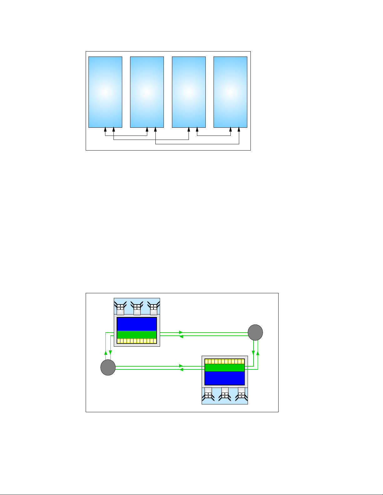
Book 0Book 3 Book 1 Book 2
Figure 2-4 Concentric ring structure
A memory-coherent director optimizes ring traffic and filters out cache traffic by not looking on
the ring for cache hits in other books if it is certain that the resources for a given logical
partition exists in the same book.
The Level 2 (L2) cache is implemented on four cache (SD) chips. Each SD chip holds 8 MB,
resulting in a 32 MB L2 cache per book. The L2 cache is shared by all PUs in the book and
has a store-in buffer design. The connection to processor memory is done through four
high-speed memory buses.
There is a ring structure within which the books maintain interbook communication at the L2
cache level. Additional books extend the function of the ring structure for interbook
communication. The ring topology is shown in Figure 2-5 and Figure 2-6 on page 31, and in
Figure 2-7 on page 31.
A book jumper completes the ring in order to be able to insert additional books into the ring
non-disruptively.
MBA Card
4 x 2 GB/S 4 x 2 GB/S
STI
STI
STI ST I
MBA
Memory Up to 64GB
MCM
MCM
Level 2 Cache 32MB
PU PUPUPU PU PU PU PU PU PU PU PU
Jumper Book
Level 2 Cache 32MB
Figure 2-5 Two-book system ring structure
4 x 2 GB/S
STI
STI
STI
STI STI
MBA
STI
STI STI
MBA
Jumper Book
Ring Structure
PU PUPUPU PU PU PU PU PU PU PU PU
Level 2 Cache 32MB
MCM
MCM
Memory Up to 64GB
MBA
MBA
STI STI
STI
MBA
STI STI
STI
STI
STI
4 x 2.5 GB/S
STI ST I
STI
STI
4 x 2.5 GB/S 4 x 2.5 GB/S
30 IBM ^ zSeries 990 Technical Guide
Page 43

MBA Card
4 x 2 GB/S 4 x 2 GB/S
STI
STI
STI STI
MBA
STI
STI STI
4 x 2 GB/S
STI
STI
STI
STI STI
MBA
MBA
Memory Up to 64GB
MCM
MCM
Level 2 Cache 32MB
PU PUPUPU PU PU PU PU PU PU PU PU
Ring Structure
Jumper Book
Figure 2-6 Three-book system ring structure
MBA Card
4 x 2 GB/S 4 x 2 GB/S
STI
STI
STI
STI STI
STI
MBA
STI STI
MBA
Memory Up to 64GB
MCM
MCM
Level 2 Cache 32MB
PU PUPUPU PU PU PU PU PU PU PU PU
PU PUPUPU PU PU PU PU PU PU PU PU
Level 2 Cache 32MB
MCM
MCM
Memory Up to 64GB
MBA
MBA
STI STI
STI STI
STI
STI
STI
4 x 2 GB/S 4 x 2 GB/S
STI
4 x 2 GB/S
STI
STI STI
MBA
MBA
STI STI
STI
4 x 2 GB/S
STI
STI
4 x 2.5 GB/S 4 x 2.5 GB/S
STI
STI
STI STI
MBA
Memory Up to 64GB
Level 2 Cache 32MB
PU PUPUPU PU PU PU PU PU PU PU PU
PU PUPUPU PU PU PU PU PU PU PU PU PU PUPUPU PU PU PU PU PU PU PU PU
Level 2 Cache 32MB
Memory Up to 64GB
MBA
STI STI
STI
STI
4 x 2.5 GB/S 4 x 2.5 GB/S
Figure 2-7 Four-book system ring structure
2.1.5 Connectivity
STI connections to I/O cages and ICB-4 links are driven from the Memory Bus Adapters
(MBAs) that are located on a separate card in the book. Figure 2-8 on page 32 shows the
location of the STI connectors and the MBA card.
MBA Card
STI
STI
STI STI
MBA
MCM
MCM
MCM
MCM
MBA
STI STI
STI
STI
MBA Card
4 x 2.5 GB/S
STI
STI STI
MBA
MBA
STI STI
STI
4 x 2.5 GB/S
STI
STI
Ring Structure
STI
STI ST I
MBA
MBA Card
STI
STI
STI
STI STI
MBA
4 x 2.5 GB/S 4 x 2.5 GB/S
Memory Up to 64GB
MCM
MCM
Level 2 Cache 32MB
PU PUPUPU PU PU PU PU PU PU PU PU
Level 2 Cache 32MB
MCM
MCM
Memory Up to 64GB
MBA
STI ST I
STI
4 x 2.5 GB/S 4 x 2.5 GB/S
MBA
STI STI
STI
STI
STI
MBA Card
4 x 2.5 GB/S
STI
STI STI
MBA
MBA
STI STI
STI
4 x 2.5 GB/S
STI
STI
Chapter 2. System structure and design 31
Page 44

MBA
LEDs
STI STI STI STI
)
FGA
MBA
P
E
E
S
STI connectors
6-ROW (720 Signal Pins
VHD M
STI ST I STI STI
MBA
STI STI STI STI
MBA card
Book front view
Figure 2-8 STI connectors and MBA card
Each book has three MBAs, each driving four STIs, resulting in 12 STIs per book.
All 12 STIs per book have a data rate of 2.0 GBps, resulting in a sustained bandwidth of 24
GBps per book. Consequently, the total instantaneous internal bandwidth of a four-book
system is 4 x 24 GBps or 96 GBps. Depending on the channel types installed, a maximum of
512 channels per CPC is currently supported.
Four STIs are related to one MBA. When configuring for availability, you should balance
channels, links, and OSAs across books, MBAs, and STIs. For z990, enhancements have
been made such that, in the unlikely event of a catastrophic failure of an MBA chip, the failure
is contained to that chip, while the other two MBAs on that book continue to operate. In a
system configured for maximum availability, alternate paths will maintain access to critical I/O
devices.
In the configuration reports, books are numbered 0, 1, 2, and 3, MBAs are numbered from 0
to 2, and the STIs are identified as jacks numbered from J.00 to J.11.
Book upgrade
As a result of a concurrent book upgrade, additional MBA and STIs connectors become
available. Since now more external connections to the I/O are potentially available, there may
be circumstances in which it might be beneficial to rebalance the total I/O configuration
across all available MBA/STIs.
Not all book upgrades will necessitate a rebalance of the I/O configuration, since the number
of STIs of the original configuration may well be able to service all existing I/O in an efficient
and balanced way.
However, if the result of the upgrade is an unbalanced I/O configuration, you should consider
rebalancing the configuration by using the additional MBA/STIs. An I/O distribution over
books, MBAs, STIs, I/O cages, and I/O cards is often desirable for both performance and
32 IBM ^ zSeries 990 Technical Guide
Page 45

availability purposes. Reports from the CHPID Mapping tool can help you validate your I/O
configuration.
Book upgrades with substantial additions of I/O cards may require the additional STIs to be
used. In that case, it is a good practice to consider rebalancing the STI configuration (FC
2400). For more information about I/O balancing, see 3.2.3, “Balancing I/O connections” on
page 79. Be aware that rebalancing of the STI configuration as a result of the addition of one
or more books is disruptive.
Book replacement and connectivity
When a book must be replaced, for example, due to an unlikely MCM failure, the MBA/STIs
connectors from the failing book are unavailable. Until the failing book is replaced, Power-On
Reset of the CPC with the remaining books is not supported.
2.1.6 Frames and cages
The z990 frames are enclosures built to Electronic Industry Association (EIA) standards. The
z990 server always has two frames that are composed of two 40 EIA frames. The A and Z
frames are bolted together and have two cage positions (top and bottom).
Frame A has the CEC cage at the top and I/O cage 1 at the bottom.
Frame Z can be one of the following configurations:
– Without I/O cage
– With one I/O cage (I/O cage 2 at the bottom)
– With two I/O cages (I/O cage 2 at the bottom and I/O cage 3 on top)
All books, the DCAs for the books, and the cooling components are located in the CEC cage
in the top half of the A-frame of the z990. In Figure 2-9, the arrows point to the front view of
the CEC cage in which four books are shown as being installed.
Z frame
IBF
IBF
BPD
I/O Cage 3
MDA MDA
MDA MDA
A frame
IBF
MRU MRU
MDA MD A
MDA
MDA
CEC Cage
I/O Cage 1I/O Cage 2
Figure 2-9 CEC cage and I/O cage locations
Chapter 2. System structure and design 33
Page 46

A frame
As shown in Figure 2-9 on page 33, the main components in the A-frame are:
1. Two Internal Battery Features (IBFs)
The optional Internal Battery Feature provides the function of a local uninterrupted power
source.
The IBF further enhances the robustness of the power design, increasing Power Line
Disturbance immunity. It provides battery power to preserve processor data in case of a
loss of power on both of the AC feeders from the utility company. The IBF can hold power
briefly over a “brownout”, or for orderly shutdown in case of a longer outage. The IBF
provides up to 20 minutes of full power, depending on I/O configuration.
2. One or two Modular Refrigeration Units (MRUs) that are air-cooled by their own internal
cooling fans.
3. The CEC cage, containing up to four books, each with two insulated refrigeration lines to
an MRU.
4. I/O Cage 1, which can house all supported types of channel cards. An I/O cage
accommodates up to 420 ESCON channels or up to 40 channels in the absence of any
other card.
5. Air-moving devices (AMD) providing N+1 cooling for the MBAs, memory, and DCAs.
Z frame
As shown in Figure 2-9 on page 33, the main components in the Z-frame are:
1. Two Internal Battery Features (IBFs) (see IBF in A frame for more information).
2. The Bulk Power Assemblies (BPAs).
3. I/O cage 2 (bottom) and I/O cage 3 (top). Note that both I/O cages are the same as the
one in the A frame, and can house all supported types of channel card.
The Z frame holds no cages, only the bottom cage (I/O cage 2), or both the bottom and top
I/O cages (I/O cage 2 and I/O cage 3).
4. The Service Element (SE) tray, which is located in front of I/O cage 2, contains the two
SEs.
I/O cages
There are 12 STI buses per book to transfer data, with a bi-directional bandwidth of 2.0 GBps
each. An STI is driven off an MBA. There are three MBAs per book, each driving four STIs,
providing an aggregated bandwidth of 24 GBps per book.
The STIs connect to I/O cages that may contain a variety of channel, coupling link,
OSA-Express, and Cryptographic feature cards:
ESCON channels (16 port cards).
FICON channels (FICON or FCP modes, two port cards).
ISC-3 links (up to four coupling links, two links per Daughter Card (ISC-D). Two Daughter
Cards plug into one Mother Card (ISC-M).
Integrated Cluster Bus (ICB) channels, both ICB-2 (333 MBps) and ICB-3 (1 GBps). Both
ICB-2 and ICB-3 (compatibility mode ICBs) require an STI extender card in the I/O cage.
OSA-Express channels:
– OSA-E Gb Ethernet
– Fast Ethernet
– 1000BASE-T Ethernet
34 IBM ^ zSeries 990 Technical Guide
Page 47

PCI Cryptographic Accelerator (PCICA, two processors per feature).
PCIX Cryptographic Coprocessor (PCIXCC, one processor per feature).
The STI-2 card provides two output ports to support the ICB-2 links. The STI-3 card
The STI-3 card provides two output ports to support the ICB-3 links. The STI-3 card
The ICB-4 channels are unique to the z990. They do not require a slot in the I/O cage and
attach directly to the STI of the communicating CPC with a bandwidth of 2.0 GBps.
2.1.7 The MCM
The z990 MultiChip Module (MCM) contains 16 chips: eight are processor chips (12 PUs),
four are System Data cache (SD) chips, one is the Storage Control (SC) chip, two chips carry
the Memory Subsystem Control function (MSC), and there is one chip for the clock
(CLK-ETR) function.
The 93 x 93 mm glass ceramic substrate on which these 16 chips are mounted has 101
layers of glass ceramic with 400 meters of internal wiring. The total number of transistors on
all chips amounts to more than 3.2 billion.
The MCM plugs into a card that is part of the book packaging, as shown in Figure 2-10. The
book itself is plugged into the CEC board to provide interconnectivity between the books, so
that a multibook system appears as a Symmetric Multi Processor (SMP). The MCM is
connected to its environment by 5184 Land Grid Arrays (LGA) connectors. Figure 2-11 on
page 36 shows the chip locations.
– High Speed Token Ring
converts the output into two 333 MBps links
converts the output into two 1GBps links.
Figure 2-10 MCM card
capacitors
PU1
PU2
SD1 SD0
SD2 SC0 SD3
PU5 PU6
CLK
PU0
PU7
MC1
PU3
PU4
MC0
capacitors
connector: cache ring / cntl power
power
Chapter 2. System structure and design 35
Page 48

MSC
PUPU
MSC
PU
PU
SD SD
SC
SD
Figure 2-11 MCM chip layout
2.1.8 The PU, SC, and SD chips
All chips use CMOS 9SG technology, except for the clock chip (CMOS 8S). CMOS 9SG is
state-of-the-art microprocessor technology based on eight-layer Copper Interconnections and
Silicon-On Insulator technologies. The chip’s lithography line width is 0.125 micron.
The eight PU chips come in two versions. The Processor Units (PUs) on the MCM in each
book are implemented with a mix of single-core and dual-core PU chips. Four single-core and
four dual-core chips are used, resulting in 12 PUs per MCM.
SD
PUPU
PU
PU
CLK
Eight PUs may be characterized for customer use, one per PU chip. The two standard SAPs
and two standard spares are initially allocated to the dual-core processor chips. Each core on
the chip runs at a cycle time of 0.83 nanoseconds. Each dual-core PU chip measures
14.1 x 18.9 mm and has 122 million transistors.
Each PU has a 512 KB on-chip Level 1 cache (L1) that is split into a 256 KB L1 cache for
instructions and a 256 KB L1 cache for data, providing large bandwidth.
SC chip
The L1 caches communicate with the L2 caches (SD chips) by two bi-directional 16-byte data
buses. There is a 2:1 bus/clock ratio between the L2 cache and the PU, controlled by the
Storage Controller (SC chip), that also acts as an L2 cache cross-point switch for L2-to-L2
ring traffic, L2-to-MSC traffic, and L2-to-MBA traffic. The L1-to-L2 interface is shared by two P
PU cores on a dual core PU chip.
36 IBM ^ zSeries 990 Technical Guide
Page 49

SD chip
The level 2 cache (L2) is implemented on the four System Data (SD) cache chips, each with a
capacity of 8 MB, providing a cache size of 32 MB. These chips measure 17.5 x 17.5 mm and
carry 521 million transistors, making them the world’s densest chips.
The dual-core PU chips share the path to the SC chip (L2 control) and the clock chip (CLK).
2.1.9 Summary
Table 2-2 summarizes all aspects of the z990 system structure.
Table 2-2 System structure summary
Number of MCMs1234
Total number of PUs12243648
IBM 2084-A08 IBM 2084-B16 IBM 2084-C24 IBM 2084-D32
Maximum number of
characterized PUs
Number of CPs 0 - 8 0 - 16 0 - 24 0 - 32
Number of IFLs 0 - 8 0 - 16 0 - 24 0 - 32
Number of ICFs 0 - 8 0 - 16 0 - 16 0 - 16
Number of zAAPs 0 - 4 0 - 8 0 - 12 0- 16
Standard SAPs2468
Standard spare PUs2468
Number of memory
cards
Enabled Memory
Sizes (multiples of 8
GB)
L1 Cache per PU 256/256 KB 256/256 KB 256/256 KB 256/256 KB
L2 Cache 32 MB 64 MB 96 MB 128 MB
Cycle time (ns) 0.83 0.83 0.83 0.83
Maximum number of
STIs
8 162432
2468
16 - 64 GB 16 - 128 GB 16 - 192 GB 16 - 256 GB
12 24 36 48
STI bandwidth/STI 2.0 GBps 2.0 GBps 2.0 GBps 2.0 GBps
Max STI bandwidth 24 GBps 48 GBps 72 GBps 96 GBps
Maximum number of
I/O cages
Number of Support
Elements
External power 3 phase 3 phase 3 phase 3 phase
Internal Battery
Feature
3333
2222
optional optional optional optional
Chapter 2. System structure and design 37
Page 50

2.2 System design
The IBM z990 Symmetrical Multi Processor (SMP) design is the next step in an evolutionary
trajectory stemming from the introduction of CMOS technology back in 1994. Over time, the
design has been adapted to the changing requirements dictated by the shift towards
e-business applications that customers are becoming more and more dependent on. The
z990, with its superscalar processor and flexible configuration options, is the next
implementation to address this ever-changing environment.
2.2.1 Design highlights
The physical packaging is a deviation from previous packaging methods in that its modular
book design creates the opportunity to address the ever-increasing costs related to building
systems with ever-increasing capacities. The modular book design is flexible and expandable
and may contain even larger capacities in the future.
The main objectives of the z990 system design, which are covered in this chapter and in the
following ones, are:
To offer a flexible infrastructure to concurrently accommodate a wide range of operating
systems and applications, from the traditional S/390 and zSeries systems to the new world
of Linux and e-business.
To have state-of-the-art
virtualization techniques, such as:
– Logical partitioning, which allows up to 30 logical servers
– z/VM, which can virtualize hundreds of servers as Virtual Machines
– HiperSockets™, which implements virtual LANs between logical and/or virtual servers
within a z990 server
This allows logical and virtual server coexistence and maximizes system utilization by
sharing hardware resources.
To h ave
e-business applications, based on z990 superscalar processor technology, architecture,
and high bandwidth channels, which offer high data rate connectivity.
To offer the
both from single system and clustered systems points of view.
To have the capability of
connectivity, avoiding server outages even in such planned situations.
To implement a system with
critical elements and sparing components of a single system, to the clustering technology
of the Parallel Sysplex environment.
To have a broad connectivity offering, supporting open standards such as Gigabit Ethernet
(GbE) and Fibre Channel Protocol (FCP) for Small Computer System Interface (SCSI).
high performance to achieve the outstanding response times required by
high capacity and scalability required by the most demanding applications,
integration capability for server consolidation, offering
concurrent upgrades for processors, memory, and I/O
high availability and reliability, from the redundancy of
To provide the highest level of
Function (CPACF). Optional PCIX Cryptographic Coprocessors and PCI Cryptographic
Accelerators for Secure Sockets Layer (SSL) transactions of e-business applications can
be added.
To b e
38 IBM ^ zSeries 990 Technical Guide
self-managing, adjusting itself on workload changes to achieve the best system
throughput, through the Intelligent Resource Director and the Workload Manager
functions.
security, each CP has a CP Assist for Cryptographic
Page 51

To have a
performance connectivity along with processor and system capacity.
The following sections describe the z990 system structure, showing a logical representation
of the data flow from PUs, L2 cache, memory cards, and MBAs, which connect I/O through
Self-Timed Interconnect (STI).
2.2.2 Book design
A book has 12 PUs, two memory cards and three MBAs connected by the System Controller
(SC). Each memory card has a capacity of 8 GB, 16 GB, or 32 GB, resulting in up to 64 GB of
memory Level 3 (L3) per book. A four-book z990 can have up to 256 GB memory. The
Storage Controller, shown as SCC CNTLR in Figure 2-12 on page 40, acts as a cross-point
switch between Processor Units (PUs), Memory Controllers (MSCs), and Memory Bus
Adapters (MBAs).
The SD chips, shown as SCD in Figure 2-12 on page 40, also incorporate a Memory
Coherent Controller (MCC) function.
Each PU chip has its own 512 KB Cache Level 1 (L1), split into 256 KB for data and 256 KB
for instructions. The L1 cache is designed as a store-through cache, meaning that altered
data is also stored to the next level of memory (L2 cache). The z990 models A08, B16, C24,
and D32 use the CMOS 9SG PU chips running at 0.83 ns.
The MCC controls a large 32 MB L2 cache, and is responsible for the interbook
communication in a ring topology connecting up to four books through two concentric loops,
called the ring structure. The MCC optimizes cache traffic and will not look for cache hits in
other books when it knows that all resources of a given logical partition are available in the
same book.
balanced system design, providing large data rate bandwidths for high
The L2 cache is the aggregate of all cache space on the SD chips, resulting in a 32 MB L2
cache per book. The SC chip (SCC) controls the access and storing of data in the four SD
chips. The L2 cache is shared by all PUs within a book and shared across books through the
ring topology, providing the communication between L2 caches across books in systems with
more than one book installed; the L2 has a store-in buffer design.
The interface between the L2 cache and processor memory (L3) is accomplished by four
high-speed memory buses and controlled by the memory controllers (MSC). Storage access
is interleaved between the storage cards, which tends to equalize storage activity across the
cards. Each memory card has two ports that each have a maximum bandwidth of 8 GBps.
Each port contains a control and a data bus, in order to further reduce any contention by
separating the address and command from the data bus.
The memory cards support store protect key caches to match the key access bandwidth with
that of the memory bandwidth.
The logical book structure is shown in Figure 2-12 on page 40.
Chapter 2. System structure and design 39
Page 52

Memory Card
PMA0
PMA1
PMA2
PMA2
PMA3PMA1
Memory Card
Store Protect Key
SM1
SM1 SM1
SM1 SM1
SM1 SM1
SM1 SM1
Store Protect Key
SM1
MCM
MSC MSC
Ring
Structure
Cache/chip
Cache/Chip
8MB
8MB
SCD
SCD
SCC
CNTLR
Cache/chip
Cache/Chip
8MB
8MB
SCD
SCD
Ring
Structure
MBA Card
MBAMBAMBA
Dual
Dual
Dual
Dual
Dual
Dual
Dual
PU PU PU PU PU PU PU PU
Cores
Cores
Cores
Cores
Cores
Cores
Cores
Dual
Cores
Up to 12 STIs
Figure 2-12 Logical book structure
There are up to 12 STI buses per book to transfer data and each STI has a bidirectional
bandwidth of 2.0 GBps. A four-book z990 server may have up to 48 STIs.
An STI is an interface from the Memory Bus Adapter (MBA) to:
An eSTI-M card in an I/O cage, to connect to:
– ESCON channels (16 port cards)
– FICON-Express channels (FICON or FCP modes, two port cards)
– OSA-Express channels (all on two port cards)
• OSA-Express Gb Ethernet
• OSA-Express Fast Ethernet
• OSA-Express 1000BASE-T Ethernet
• OSA-Express High Speed Token Ring
– ISC-3 links (up to four coupling links, two links per Daughter Card (ISC-D). Two
Daughter Cards plug into one Mother Card (ISC-M).
– PCIX Cryptographic Coprocessors (PCIXCC) in an I/O cage. Each PCIX
Cryptographic Coprocessor feature contains one cryptographic coprocessor.
– PCI Cryptographic Accelerator (PCICA) in an I/O cage. Each PCI Cryptographic
Accelerator feature contains two cryptographic accelerator cards.
An STI-2 card in an I/O cage, connecting to ICB-2 channels in 9672 G5/G6 servers.
An STI-3 card in an I/O cage, connecting to ICB-3 channels in z800 or z900 servers.
ICB-4, directly attached to the 2.0 GBps STI interface between z990 or z890 servers.
40 IBM ^ zSeries 990 Technical Guide
Page 53

Data transfer between the CEC memory and attached I/O devices or CPCs is done through
the Memory Bus Adapter. The physical path includes the Channel card (except for STI
connected CPCs), the Self-Timed Interconnect bus, and possibly a STI extender card, the
Storage Control, and the Storage Data chips.
More detailed information about I/O connectivity and channel types can be found in
Chapter 2.2.12, “I/O subsystem” on page 71.
Dual External Time Reference
The optional ETR connections, although not part of the book design, are found adjacent to
the books on the opposite side of the CEC board. The z990 servers implement an Enhanced
ETR Attachment Facility (EEAF) designed to provide a dual External Time Reference (ETR)
attachment facility. Two ETR cards are automatically shipped when Coupling Links are
ordered and provide a dual path interface to the IBM Sysplex Timers, which are used for
timing synchronization between systems in a Sysplex environment. This allows continued
operation even if a single ETR card fails. This redundant design also allows concurrent
maintenance.
2.2.3 Processor Unit design
Each PU is optimized to meet the demands of new e-business workloads, without
compromising the performance characteristics of traditional workloads. The PUs in the z990
have a superscalar design.
Superscalar processor
A scalar processor is a processor that is based on a single issue architecture, which means
that only a single instruction is executed at a time. A superscalar processor allows concurrent
execution of instructions by adding additional resources onto the microprocessor to achieve
more parallelism by creating multiple pipelines, each working on their own set of instructions.
A superscalar processor is based on a multi-issue architecture. In such a processor, where
multiple instructions can be executed at each cycle, a higher level of complexity is reached
because an operation in one pipeline may depend on data in another pipeline. A superscalar
design therefore demands careful consideration of which instruction sequences can
successfully operate in a multi-pipeline environment.
As an example, consider the following: If the branch prediction logic of the microprocessor
makes the wrong prediction, it might be necessary to remove all instructions in the parallel
pipelines also (refer to “Processor Branch History Table (BHT)” on page 44 for more details).
There are challenges in creating an efficient superscalar processor. The superscalar design
of the z990 PU has made big strides in avoiding address generation interlock situations.
Instructions requiring information from memory locations may suffer multi cycle delays to get
the memory content. The superscalar design of the z990 PU tries to overcome these delays
by continuing to execute (single cycle) instructions that do not cause delays. The technique
used is called “out-of-order operand fetching”. This means that some instructions in the
instruction stream are already underway, while earlier instructions in the instruction stream
that cause delays due to storage references take longer. Eventually, the delayed instructions
catch up with the already fetched instructions and all are executed in the designated order.
The z990 PU gets much of its superscalar performance benefits from avoiding address
generation interlocks.
It is not only the processor that contributes to the capability of the successful execution of
instructions in parallel. Given a superscalar design, compilers and interpreters must create
code that benefit optimally from the particular superscalar processor implementation. Work is
Chapter 2. System structure and design 41
Page 54

under way to update the C++ compiler and Java Virtual Machine for z/OS to better exploit the
z990 microprocessor superscalar implementation. The intent is improve the performance
advantage for e-business workloads such as WebSphere and Java applications.
By the time the Java Virtual Machine (JVM) and compilers are available, more improvement in
the throughput of the superscalar processor is expected. In order to create instruction
sequences that are least affected by interlock situations, instruction grouping rules are
enforced to create instruction streams that benefit most from the superscalar processor. It is
expected that e-business workloads will primarily benefit from this design since they tend to
use more computational instructions.
A WebSphere Application Server workload environment that runs a mix of Java and DB2
code will greatly benefit from the superscalar processor design of the z990. Measurements
already show a larger than 20% performance improvement for these types of workloads, on
top of the improvements attributed to the cycle time decrease from 1.09 ns on a z900 Turbo
model to 0.83 ns on a z990.
The superscalar design of the z990 microprocessor means that some instructions are
processed immediately and that processing steps of other instructions may occur out of the
normal sequential order, called “pipelining”. The superscalar design of the z990 offers:
Decoding of two instructions per cycle
Execution of three instructions per cycle (given that the oldest instruction is a branch)
In-order execution
Out-of-order operand fetching
Other features of the microprocessor, aimed at improving the performance of the emerging
e-business application environment, are:
Floating point performance for IEEE Binary Floating Point arithmetic is improved to assist
further exploitation of Java application environments.
A secondary cache for Dynamic Address Translation, called the Secondary level
Translation Lookaside Buffer (TLB), is provided for both L2 instruction and data caches,
increasing the number of buffer entries by a factor of eight.
The CP Assist for Cryptographic Function (CPACF) accelerates the encryption and
decryption of SSL transactions and VPN encrypted data transfers. The assist function
uses five new instructions for symmetrical clear key cryptographic encryption and
encryption operations.
Asymmetric mirroring for error detection
Each PU in the z990 servers uses mirrored instruction execution as a simple error detection
mechanism. The mirroring is dependent on a dual instruction processor design with dual
I-units, and E-units and floating point function. It is asymmetric because the mirrored
execution is delayed from the actual operation. The benefit of the asymmetric design is that
the mirrored units do not have to be closely located to the units where the actual operation
takes place, thus allowing for optimization for performance (see Figure 2-13 on page 43).
42 IBM ^ zSeries 990 Technical Guide
Page 55

From L2 Cache
From E-Unit From E-Unit
I-Unit
E-Unit
B-Unit
L1
Cache
To L2 Cache
I-Unit
E-Unit
R-Unit
Floating p
Fixed p
COMPARE
Error
Detecti on
Floating p
Fixed p
Processing Unit (PU)
Dual processor
I-Unit
E-Unit
Floating Point function
Simple yet complete error detection
mechanism
Data flow - parity checked
Address paths - parity checked
L1 Cache - parity checked
Processor logic (I - E - F) -
Duplicated, then compared output.
Error detection for mis-compare
To B-Unit
Figure 2-13 Dual (asymmetric) processor design
To B-Unit
Each PU has a dual processor and each processor has its own Instruction Unit (I-Unit) and
Execution Unit (E-Unit), which includes the floating point function. The instructions are
executed asymmetrically (not exactly in parallel) on each processor and compared after
processing.
This design simplifies error detection during instruction execution, saving additional circuits
and extra logic required to do this checking. The z990 servers also contain error-checking
circuits for data flow parity checking, address path parity checking, and L1 cache parity
checking.
Compression Unit on a chip
Each z990 PU has a Compression Unit on the chip, providing excellent hardware
compression performance. The Compression Unit is integrated with the CP Assist for
Cryptographic Function, benefiting from combining the use of buffers and interfaces.
CP Assist for Cryptographic Function
Each z990 PU has a CP Assist for Cryptographic Function on the chip. The assist provides
high performance hardware encryption and decryption support for clear key operations. To
that end, five new instructions are introduced with the cryptographic assist function.
The CP Assist for Cryptographic Function offers a set of symmetric cryptographic functions
that enhance the encryption and decryption performance of clear key operations for SSL,
VPN, and data storing applications that do not require FIPS 140-2 level 4 security. The
cryptographic architecture includes DES, T-DES data encryption and decryption, MAC
message authorization, and SHA-1 hashing.
The CP Assist for Cryptographic Function complements public key (RSA) functions and the
secure cryptographic operations provided by the PCIXCC cryptographic coprocessor card.
See Chapter 5, “Cryptography” on page 119 for more information about the cryptographic
features on the z.990.
Chapter 2. System structure and design 43
Page 56

Processor Branch History Table (BHT)
The Branch History Table (BHT) implementation on processors has a key performance
improvement effect. The BHT was originally introduced on the IBM ES/9000® 9021 in 1990
and has been improved ever since.
The z990 server BHT offers significant branch performance benefits. The BHT allows each
CP to take instruction branches based on a stored BHT, which improves processing times for
calculation routines. Using a 100-iteration calculation routine as an example (Figure 2-14),
the hardware preprocesses the branch incorrectly 99 times without a BHT. With a BHT, it
preprocesses branch correctly 98 times.
Without BHT:
Hardware branch
guess OK
Hardware branch
guess not OK
99 of 100 times
Guess Path
Actual Path
Figure 2-14 Branch History Table (BHT)
Without BHT, the processor:
– Makes an incorrect branch guess the first time through the loop (at the second branch
point in Figure 2-14).
– Preprocesses instructions for the guessed branch path.
– Starts preprocessing a new path if the branch not equal to the guess.
– Repeats this 98 more times until the last time, when the guess matches the actual
branch taken
With BHT:
Hardware branch guess OK
Hardware branch
guess OK
98 of 100 times
Guess Path
Actual Path
With BHT, the processor:
– Makes an incorrect branch guess the first time through the loop (at the second branch
point in Figure 2-14).
– Preprocesses instructions for the guessed branch path.
– Starts preprocessing a new path if the branch is not equal to the guess.
– Updates the BHT to indicate the last branch action taken at this address.
– The next 98 times, the branch path comes from the BHT.
– The last time, the guess is wrong.
The key point is that, with the BHT, the table is updated to indicate the last branch action
taken at branch addresses. Using the BHT, if a hardware branch at an address matches a
BHT entry, the branch direction is taken from the BHT. Therefore, in the diagram, the
branches are correct for the remainder of the loop through the program routine, except for the
last one.
44 IBM ^ zSeries 990 Technical Guide
Page 57

The success rate that the BHT design offers contributes a great deal to the superscalar
aspects of the z990, given the fact that the architecture rules prescribe that for successful
parallel execution of an instruction stream, the correctly predicted result of the branch is
essential.
IEEE Floating Point
The inclusion of the IEEE Standard for Binary Floating Point Arithmetic (IEEE 754-1985) in
S/390 was made to further enhance the value of this platform for this type of calculation. The
initial implementation had 121 floating-point instructions over prior S/390 CMOS models
(Hexadecimal Floating Point had 54 instructions). Later, with the introduction of the 64-bit
architecture, 12 additional instructions were added for IEEE Binary Floating Point Arithmetic
64-bit integer conversion.
The key point is that Java and C/C++ applications tend to use IEEE Binary Floating Point
operations more frequently than legacy applications. This means that the better the hardware
implementation of this set of instructions, the better the performance of e-business
applications will be.
On earlier systems, the emphasis has been on the traditional hexadecimal floating point
arithmetic. The z990 has a Binary Floating Point unit that matches the performance of the
traditional hexadecimal floating point unit by halving the number of cycles required earlier.
Translation Lookaside Buffer
The Translation Lookaside Buffer (TLB) in the Instruction and Data L1 caches now have a
secondary TLB to enhance performance. In addition, a translator unit is added to translate
misses in the secondary TLB.
Instruction fetching and instruction decode
The superscalar design of the z990 microprocessor allows for the decoding of up to two
instructions per cycle and the execution of three instructions per cycle. Execution takes place
in order, but storage accesses for instruction and operand fetching may occur out of
sequence.
Instruction fetching
Instruction fetch in non-z990 models tries to get as far ahead of instruction decode and
execution as possible because of the relatively large instruction buffers available. In the z990
microprocessor, smaller instruction buffers are used. The operation code is fetched from the
I-cache and put in instruction buffers that hold pre-fetched data awaiting decode.
Instruction decoding
The processor can decode one or two instruction per cycle. The result of the decoding
process is queued and subsequently used to form a group.
Instruction grouping
From the instruction queue, one simple branch instruction and up to two general instructions
can be issued every cycle. The instructions are taken from the instruction queue and grouped
together. The instructions are assembled according to instruction grouping rules. A complete
description of the rules is beyond the scope of this redbook.
It is the compiler’s responsibility to select instructions that best fit with the z990 superscalar
microprocessor and abide by the grouping rules to create code that best exploits the
superscalar implementation.
Chapter 2. System structure and design 45
Page 58

Extended Translation Facility
The Extended Translation Facility adds 10 instructions to the zSeries instruction set. They
enhance the performance for data conversion operations for data encoded in Unicode,
making applications enabled for Unicode and/or Globalization more efficient. These data
encoding formats are used in Web Services, Grid, and on demand environments where XML
and SOAP technologies are used. The High Level Assembler will be the first to support the
Extended Translation Facility instructions.
2.2.4 Processor Unit functions
One of the key components of the z990 server is the Processor Unit (PU). This is the
microprocessor chip where instructions are executed and the related data resides. The
instructions and the data are stored in the PU’s high-speed buffer, called the Level 1 cache.
Each PU has its own 512 KB Level 1 cache, split into 256 KB for data and 256 KB for
instructions.
The L1 cache is designed as a store-through cache, which means that altered data is
synchronously stored into the next level, the L2 cache. Each PU has multiple processors
inside and instructions are executed twice, asynchronously, on both processors.
This asymmetric mirroring of instruction execution runs one cycle behind the actual operation.
This allows the circuitry on the chip to be optimized for performance and does not
compromise the simplified error detection process that is inherent to a mirrored execution unit
design.
One or two Processor Units are contained on one processor chip. All PUs of a z990 server
reside in a MultiChip Module. An MCM holds 12 PUs, of which eight are available for
customer use, two are SAPs, and two are spares. Up to four MCMs, each contained in a
book, may be available in one z990 server.
This approach allows a z990 server to have more PUs than required for a given initial
configuration. This is a key point of the z990 design and is the foundation for the configuration
flexibility and scalability of a single server.
All PUs in a z990 server are physically identical, but at initialization time PUs can be
characterized to specific functions: CP, IFL, ICF, zAAP, or SAP. The function assigned to a PU
is set by the Licensed Internal Code loaded when the system is initialized (Power-on Reset)
and the PU is “characterized”. Only characterized PUs have a designated function;
non-characterized PUs are considered spares.
This design brings an outstanding flexibility to the z990 server, as any PU can assume any
available characterization. This also plays an essential role in z990 system availability, as
these PU assignments can be done dynamically, with no server outage, allowing:
Concurrent upgrades
Except on a fully configured model, concurrent upgrades can be done by the Licensed
Internal Code, which assigns a PU function to a previously non-characterized PU. Within
the book boundary or boundary of multiple books, no hardware changes are required, and
the upgrade can be done via Capacity Upgrade on Demand (CUoD), Customer Initiated
Upgrade (CIU), On/Off Capacity on Demand (On/Off CoD), or Capacity BackUp (CBU).
More information about capacity upgrades is provided in 8.1, “Concurrent upgrades” on
page 188.
46 IBM ^ zSeries 990 Technical Guide
Page 59

PU sparing
In the rare case of a PU failure, the failed PU’s characterization is dynamically and
transparently reassigned to a spare PU. More information on PU sparing is provided in
“Sparing rules” on page 52.
A minimum of one PU per z990 server must be ordered as one of the following:
A Central Processor (CP)
An Integrated Facility for Linux (IFL)
An Internal Coupling Facility (ICF)
The number of CPs, IFLs, ICFs, zAAPs, or SAPs assigned to particular models depends on
the configuration. The z990 12-PU MCMs have two SAPs as standard. The standard number
of SAPs in a model A08 is two; there are four in a B16, six in a C24, and eight in a D32.
Optional additional SAPs may be purchased, up to two per book.
The z990 12-PU MCMs have two spares PUs as standard. The standard number of spares in
a model A08 is two; there are four in a B16, six in a C24, and eight in a D32. The number of
additional spare PUs is dependent on the number of books in the configuration and how many
PUs are non-characterized.
Central Processors
A Central Processor is a PU that has the z/Architecture and ESA/390 instruction sets. It can
run z/Architecture, ESA/390, Linux, and TPF operating systems, and the Coupling Facility
Control Code (CFCC).
The z990 can only be used in LPAR mode. In LPAR mode, CPs can be defined as dedicated
or shared to a logical partition. Reserved CPs can be defined to a logical partition, to allow for
non-disruptive
All CPs within a z990 configuration are grouped into a CP pool. Any z/Architecture, ESA/390,
Linux, and TPF operating systems, and CFCC can run on CPs that are assigned from the CP
pool.
Within the limit of all non-characterized PUs available in the installed configuration, CPs can
be concurrently assigned to an existing configuration via Capacity Upgrade on Demand
(CUoD), Customer Initiated Upgrade (CIU), On/Off Capacity on Demand (On/Off CoD), or
Capacity BackUp (CBU). More information about all forms of concurrent CP adds are found in
Chapter 8, “Capacity upgrades” on page 187.
If the MCMs in the installed books have no available PUs left, the assignment of the next CP
may result in the need for a model upgrade and the installation of an additional book. Book
installation is a non-disruptive action, but will take more time than a simple Licensed Internal
Code upgrade. Only if reserved processors have been defined to a logical partition—and
when the operating system supports the function—can additional CP capacity be allocated to
the logical partition dynamically.
image upgrades. The z990 can have up to 32 CPs.
Integrated Facilities for Linux
An Integrated Facility for Linux (IFL) is a PU that can be used to run Linux on zSeries, Linux
for S/390, or Linux guests on z/VM operating systems. Up to 32 PUs may be characterized as
IFLs, depending on the z990 model. IFL processors can be dedicated to a Linux or a z/VM
logical partition, or be shared by multiple Linux guests and/or z/VM logical partitions running
on the same z990 server. Only z/VM, Linux on zSeries, and Linux for S/390 operating
systems can run on IFL processors.
Chapter 2. System structure and design 47
Page 60

All PUs characterized as IFL processors within a configuration are grouped into the
ICF/IFL/zAAP processor pool. The ICF/IFL/zAAP processor pool appears on the hardware
console as ICF processors. The number of ICFs shown is the sum of IFL, ICF, and zAAP
processors on the server.
IFLs do not change the software model number of the z990 server. Software product license
charges based on the software model number are not affected by the addition of IFLs.
Within the limit of all non-characterized PUs available in the installed configuration, IFLs can
be concurrently added to an existing configuration via Capacity Upgrade on Demand (CUoD),
Customer Initiated Upgrade (CIU), On/Off Capacity on Demand (On/Off CoD), but IFLs
cannot be assigned via CBU. For more information about CUoD, CIU or On/Off CoD see
Chapter 8, “Capacity upgrades” on page 187. If the installed books have no unassigned PUs
left, the assignment of the next IFL may require the installation of an additional book.
Internal Coupling Facilities
An Internal Coupling Facility (ICF) is a PU used to run the IBM Coupling Facility Control Code
(CFCC) for Parallel Sysplex environments. Within the capacity of the sum of all unassigned
PUs in up to four books, up to 16 ICFs can be characterized, depending on the z990 model.
You need at least an IBM 2084 model B16 to assign 16 ICFs. ICFs can be concurrently
assigned to an existing configuration via Capacity Upgrade on Demand (CUoD), On/Off
Capacity on Demand (On/Off CoD), or Customer Initiated Upgrade (CIU), but ICFs
assigned via CBU.
For more information about CUoD, CIU, or On/Off CoD, see Chapter 8, “Capacity upgrades”
on page 187. If the installed books have no non-characterized PUs left, the assignment of the
next ICF may require the installation of an additional book.
cannot be
The ICF processors can only be used by Coupling Facility logical partitions. ICF processors
can be dedicated to a CF logical partition, or shared by multiple CF logical partitions running
in the same z990 server.
All ICF processors within a configuration are grouped into the ICF/IFL/zAAP processor pool.
The ICF/IFL/zAAP processor pool appears on the hardware console as ICF processors. The
number of ICFs shown is the sum of IFL, ICF, and zAAP processors on the system.
Only Coupling Facility Control Code (CFCC) can run on ICF processors; ICFs do not change
the model type of the z990 server. This is important because software product license
charges based on the software model number are not affected by the addition of ICFs.
Dynamic ICF Expansion
Dynamic ICF Expansion is a function that allows a CF logical partition running on dedicated
ICFs to acquire additional capacity from the LPAR pool of shared CPs or shared ICFs. The
trade-off between using ICF features or CPs in the LPAR shared pool is the exemption from
software license fees for ICFs. Dynamic ICF Expansion is available on any z990 model that
has at least one ICF.
Dynamic ICF Expansion requires that the Dynamic CF Dispatching be turned on (DYNDISP
ON). For more information, see 7.2.7, “Dynamic CF dispatching and dynamic ICF expansion”
on page 168.
Dynamic Coupling Facility Dispatching
The Dynamic Coupling Facility Dispatching function has an enhanced dispatching algorithm
that lets you define a backup Coupling Facility in a logical partition on your system. While this
logical partition is in backup mode, it uses very little processor resource. When the backup CF
becomes active, only the resource necessary to provide coupling is allocated.
48 IBM ^ zSeries 990 Technical Guide
Page 61

The CFCC command DYNDISP controls the Dynamic CF Dispatching (use DYNDISP ON to
enable the function). For more information, see 7.2.7, “Dynamic CF dispatching and dynamic
ICF expansion” on page 168.
zSeries Application Assist Processors
The zSeries Application Assist Processor (zAAP) is a PU that is used exclusively for running
Java application workloads under z/OS. One CP must be installed with or prior to any zAAP
being installed. The number of zAAPs in a machine cannot exceed the number of CPs plus
unassigned CPs in that machine. Within the capacity of the sum of all unassigned PUs in up
to four books, up to 16 zAAPs can be characterized, depending on the z990 model. Up to four
zAAPs can be characterized per book. You need an IBM 2084 model D32 with a total of 16
assigned and unassigned CPs to assign 16 zAAPs.
Within the limit of all non-characterized PUs available in the installed configuration, zAAPs
can be concurrently added to an existing configuration via Capacity Upgrade on Demand
(CUoD), Customer Initiated Upgrade (CIU), On/Off Capacity on Demand (On/Off CoD), but
zAAPs
With On/Off CoD, you may concurrently install temporary zAAP capacity by ordering On/Off
CoD Active zAAP features up to the number of current zAAPs that are permanently
purchased. Also, the total number of On/Off CoD Active zAAPs plus zAAPs cannot exceed
the number of On/Off Active CPs plus the number of CPs plus the number unassigned CPs
on a z990 server.
For more information about CUoD, CIU, or On/Off CoD, see Chapter 8, “Capacity upgrades”
on page 187. If the installed books have no unassigned PUs left, the assignment of the next
zAAP may require the installation of an additional book.
cannot be assigned via CBU.
PUs characterized as zAAPs within a configuration are grouped into the ICF/IFL/zAAP
processor pool. The ICF/IFL/zAAP processor pool appears on the hardware console as ICF
processors. The number of ICFs shown is the sum of IFL, ICF, and zAAP processors on the
server.
zAAPs are orderable by feature code (FC 0520). Up to one zAAP can be ordered for each CP
or unassigned CP configured in the machine.
Important: The zAAP is a specific example of an assist processor that is known
generically as an Integrated Facility for Applications (IFA). The generic term IFA often
appears in panels, messages, and other online information relating to the zAAP.
zAAPs and LPAR definitions
zAAP processors can be defined as dedicated or shared processors in a logical partition and
are always related to CPs of the same partition. For a logical partition image, both CPs and
zAAPs logical processors are either dedicated or shared.
Purpose of a zAAP
zAAPs are designed for z/OS Java code execution. When Java code must be executed (that
is, under control of Websphere), the z/OS Java Virtual Machine (JVM) calls the function of the
zAAP. The z/OS dispatcher then suspends the JVM task on the CP it is running on and
dispatches it on an available zAAP. After the Java application code execution is finished, the
z/OS dispatcher redispatches the JVM task on an available CP, after which normal processing
is resumed. This reduces the CP time needed to run WebSphere applications, freeing
capacity for other workloads.
Chapter 2. System structure and design 49
Page 62

A zAAP only executes Java Virtual Machine (JVM) code and is the only authorized user of a
zAAP in association with some z/OS infrastructural code as the z/OS dispatcher and
supervisor services. A zAAP is not able to process I/O or clock comparator interruptions and
does not support operator controls like IPL.
Java application code can either run on a CP or an zAAP. The user can manage the use of
CPs such that Java application code runs only on a CP, only on an zAAP, or on both when
zAAPs are busy.
For the logical flow of a Java code execution on a zAAP, see Figure 6-3 on page 139.
Software support
zAAPs do not change the software model number of the z990 server. IBM software product
license charges based on the software model number are not affected by the addition of
zAAPs.
z/OS Version 1.6 is a prerequisite for supporting zAAPs, together with IBM SDK for z/OS Java
2 Technology Edition V1.4.1.
Exploiters of zAAPs include:
WebSphere Application Server 5.1
CICS/TS 2.3
DB2® Version 8
IMS™ Version 8
WebSphere WBI for z/OS
System Assist Processors
A System Assist Processor (SAP) is a PU that runs the Channel Subsystem Licensed Internal
Code to control I/O operations.
All SAPs perform I/O operations for all logical partitions. All z990 models have standard SAPs
configured. The IBM 2084 model A08 has two SAPs, the model B16 has four SAPs, the
model C24 has six SAPs, and the model D32 has eight SAPs as the standard configuration.
Channel cards are assigned across SAPs to balance SAP utilization and improve I/O
subsystem performance.
A standard SAP configuration provides a very well-balanced system for most environments.
However, there are application environments with very high I/O rates (typically some TPF
environments). In this case, optional additional SAPs can be ordered. Assignment of
additional SAPs can increase the capability of the Channel Subsystem to perform I/O
operations.
In z990 servers, the number of SAPs can be greater than the number of CPs and the number
of used STIs.
Optional additional orderable SAPs
An option available on all models is additional orderable SAPs. These additional SAPs
increase the capacity of the Channel Subsystem to perform I/O operations, usually suggested
for TPF environments. The maximum number of optional additional orderable SAPs depends
on the model and the number of available uncharacterized PUs in the configuration:
IBM 2084-A08: Maximum additional orderable SAPs is two.
IBM 2084-B16: Maximum additional orderable SAPs is four.
50 IBM ^ zSeries 990 Technical Guide
Page 63

IBM 2084-C24: Maximum additional orderable SAPs is six.
IBM 2084-D32: Maximum additional orderable SAPs is eight.
Optionally assignable SAPs
Assigned CPs may be optionally reassigned as SAPs instead of CPs, using the Reset Profile
on the Hardware Management Console (HMC). This reassignment increases the capacity of
the Channel Subsystem to perform I/O operations, usually for some specific workloads or I/O
intensive testing environments.
If you intend to activate a modified server configuration with a modified SAP configuration, a
reduction in the number of CPs available will reduce the number of logical processors you can
activate. Activation of a logical partition will fail if the number of logical processors you attempt
to activate exceeds the number of CPs available. To avoid a logical partition activation failure,
you should verify that the number of logical processors assigned to a logical partition does not
exceed the number of CPs available.
Note: Concurrent upgrades are not supported with CPs defined as additional SAPs.
Reserved processors
Reserved processors can be defined to a logical partition. Reserved processors are defined
by the Processor Resource/System Manager (PR/SM) to allow non-disruptive
upgrade. Reserved processors are like “spare logical processors.” They can be defined as
Shared or Dedicated.
capacity
Reserved processors can be dynamically configured online by an operating system that
supports this function if there are enough unassigned PUs available to satisfy this request.
The previous PR/SM rules regarding logical processor activation remain unchanged.
Reserved processors also provide the capability of defining to a logical partition more logical
processors than the number of available CPs, IFLs, ICFs, and zAAPs in the configuration.
This makes it possible to configure online, non-disruptively, more logical processors after
additional CPs, IFLs, ICFs, and zAAPs have been made available concurrently, via CUoD,
CIU, and On/Off CoD for CPs, IFLs, ICFs, and zAAPs, or CBU for CPs. See 8.1, “Concurrent
upgrades” on page 188 for more details.
When no reserved processors are defined to a logical partition, a processor upgrade in that
logical partition is disruptive, requiring the following tasks:
1. Partition deactivation
2. A Logical Processor definition change
3. Partition activation
The maximum number of Reserved processors that can be defined to a logical partition
depends upon the number of logical processors that are defined. For an ESA/390 mode
logical partition the sum of defined and reserved logical processors is limited to 32, including
CPs and zAAPs. However up to 24 processors, including CPs and zAAPs, are planned to be
supported by z/OS 1.6. The z/VM 5.1 is planned to support up to 24 processors, either all
CPs or all IFLs.
For more information about logical processors and reserved processors definition, see
“Logical Partitioning overview” on page 57.
Chapter 2. System structure and design 51
Page 64

Processor Unit characterization
Processor Unit (PU) characterization is done at Power-on Reset time when the server is
initialized. The z990 is always initialized in LPAR mode, and it is the PR/SM hypervisor that
has responsibility for the PU assignment.
Additional SAPs are characterized first, then CPs, followed by IFLs, ICFs, and zAAPs. For
performance reasons, CPs for a logical partition are grouped together as much as possible.
Having all CPs grouped in as few books as possible limits memory and cache interference to
a minimum.
When an additional book is added concurrently after Power-on Reset and new logical
partitions are activated, or processor capacity for active partitions is dynamically expanded,
the additional PU capacity may be assigned from the new book. It is only after the next
Power-on Reset that the Processor Unit allocation rules take into consideration the newly
installed book.
Note: Even in a multi-book system, a book failure is a CPC system failure. Until the failing
book is repaired or replaced, Power-On Reset of the z990 with the remaining books is not
supported.
Transparent CP, IFL, ICF, zAAP, and SAP sparing
Characterized PUs, whether CPs, IFLs, ICFs, zAAPs, or SAPs, are transparently spared,
following distinct rules.
The z990 server comes with two, four, six, or eight standard spare PUs, depending on the
model. CP, IFL, ICF, zAAP, and SAP sparing is completely transparent and requires no
operating system or operator intervention.
With transparent sparing, the application that was running on the failed processor is
preserved and will continue processing on a newly assigned CP, IFL, ICF, zAAP, or SAP
(allocated to one of the spare PUs) without customer intervention. If no spare PU is available,
Application preservation is invoked.
Application preservation
Application preservation is used in the case where a processor fails and there are no spare
PU available. The state of the failing processor is passed to another active processor used by
the operating system and, through operating system recovery services, the task is resumed
successfully—in most cases without customer intervention.
Dynamic SAP sparing and reassignment
Dynamic recovery is provided in case of failure of the System Assist Processor (SAP). In the
event of a SAP failure, if a spare PU is available, the spare PU will be dynamically assigned
as a new SAP. If there is no spare PU available, and more than one CP is characterized, a
characterized CP is reassigned as a SAP. In either case, there is no customer intervention
required. This capability eliminates an unplanned outage and permits a service action to be
deferred to a more convenient time.
Sparing rules
The sparing rules for the allocation of spare CPs, IFLs, ICFs, zAAPs, and SAPs depend on
the type of processor chip on which the failure occurs. On each MCM, two standard spare
PUs are available. The two standard SAPs and two standard spares are initially allocated to
dual core processor chips. Table 2-3 on page 53 illustrates the default PU-to-chip mapping.
52 IBM ^ zSeries 990 Technical Guide
Page 65

Table 2-3 PU chip allocation
Core Core X = CP, IFL, ICF, or zAAP
Single core
Dual core 8 9 X Spare
0- X -
2- X -
4- X -
6- X -
A B X Spare
C D X SAP
E F X SAP
On a single-book configuration, model A08:
– When a PU failure occurs on a dual-core chip, the two standard spares PUs are used
to recover the failing chip, even though only one of the PUs has failed.
– When a failure occurs on a PU on a single-core chip, one standard spare PU is used.
The system does not issue an RSF call in either of the above circumstances.
When a non-characterized PU is used as a spare, in case the system has run out of the
standard spares, or when all PUs have been assigned and no non-characterized PU
remains available, an RSF call occurs to request a book repair.
On a multi-book configuration, models B16, C24, or D32:
– In a first step, the standard spare PUs of the MCM where the failing PU resides is
assigned as spare, in the same manner as for a one-book system.
– In a second step, when there are not enough spares in the book with the failing PU,
non-characterized PUs in other books are used for sparing. When “cross-book” sparing
occurs, the book closest to the one with the failing PU will be used.
For example, if a PU failure in Book-1 cannot be solved within locally, spares in Book-2
or Book-0 are then selected. When no spares are available in any adjacent book,
Book-3 is approached for a spare PU.
2.2.5 Memory design
As for PUs and the I/O subsystem designs, the z990 memory design equally provides great
flexibility and high availability, allowing:
Concurrent Memory upgrades (except when the physically installed capacity is reached.)
The z990 servers may have more physically installed memory than the initial available
capacity. Memory upgrades within the physically installed capacity can be done
concurrently by the Licensed Internal Code, and no hardware changes are required.
Concurrent memory upgrades can be done via Capacity Upgrade on Demand or
Customer Initiated Upgrade. Note that memory upgrades
BackUp (CBU); see Table 8-1 on page 190 for more information.
cannot be done via Capacity
Chapter 2. System structure and design 53
Page 66

Dynamic Memory sparing
The z990 does not contain spare memory DIMMs. Instead, it has redundant memory
distributed throughout its operational memory and this is used to bypass failing memory.
Replacing memory cards requires the removal of a book and this is disruptive. The
extensive use of redundant elements in the operational memory greatly minimizes the
possibility of a failure that requires memory card replacement.
Partial Memory Restart
In the rare event of a memory card failure, Partial Memory Restart enables the system to
be restarted with only part of the original memory. In a one-book system, the failing card
will be deactivated, after which the system can be restarted with the memory on the
remaining memory card.
In a system with more than one book, all physical memory in the book containing the
failing memory card is taken offline, allowing you to bring up the system with the remaining
physical memory in the other books. In this way, processing can be resumed until a
replacement memory card is installed.
Memory error-checking and correction code detects and corrects single-bit errors, or 2-bit
errors from a chipkill failure, using the Error Correction Code (ECC). Also, because of the
memory structure design, errors due to a single memory chip failure are corrected.
Memory background scrubbing provides continuous monitoring of storage for the correction
of detected faults before the storage is used.
The memory cards use the latest fast 256 Mb, and 512 Mb, synchronous DRAMs. Memory
access is interleaved between the memory cards to equalize memory activity across the
cards.
Memory cards have 8 GB, 16 GB, or 32 GB of capacity. All memory cards installed in one
book must have the same capacity. Books may have different memory sizes, but the card size
of the two cards per book must always be the same.
The total capacity installed may have more usable memory than required for a configuration,
and Licensed Internal Code Configuration Control (LIC-CC) will determine how much
memory is used from each card. The sum of the LIC-CC provided memory from each card is
the amount available for use in the system.
Memory allocation
Memory assignment or allocation is done at Power-on Reset (POR) when the system is
initialized. Actually, PR/SM is responsible for the memory assignments; it is PR/SM that
controls the resource allocation of the CPC. Table 2-1 on page 28 shows the distribution of
physical memory across books when a system initially is installed with the amounts of
memory shown in the first column. However, the table gives no indication of
memory is allocated. Memory allocation is done as evenly as possible across all installed
books.
PR/SM has knowledge of the amount of purchased memory and how it relates to the
available physical memory in each of the installed books. PR/SM has control over all physical
memory and therefore is able to make physical memory available to the configuration when a
book is non-disruptively added. PR/SM also controls the reassignment of the content of a
specific physical memory array in one book to a memory array in another book. This is known
as the Memory Copy/Reassign function.
where the initial
Due to the memory allocation algorithm, systems that undergo a number of MES upgrades for
memory can have a variety of memory card mixes in all books of the system. If, however
54 IBM ^ zSeries 990 Technical Guide
Page 67

unlikely, memory should fail, it is technically feasible to Power-on Reset the system with the
remaining memory resources (see “Partial Memory Restart” on page 54). After Power-on
Reset, the memory distribution across the books is now different, as is the amount of
memory.
Capacity Upgrade on Demand (CUoD) for memory can be used to order more memory than
needed on the initial model, but that is required on the target model; see “Memory upgrades”
on page 29. For more information about CUoD for memory, refer to “CUoD for memory” on
page 193.
Processor memory, even though physically the same, can be configured as both Central
storage and Expanded storage.
Central storage (CS)
Central storage (CS) consists of main storage, addressable by programs, and storage not
directly addressable by programs. Non-addressable storage includes the Hardware System
Area (HSA). Central storage provides:
Data storage and retrieval for the PUs and I/O
Communication with PUs and I/O
Communication with and control of optional expanded storage
Error checking and correction
Central storage can be accessed by all processors, but cannot be shared between logical
partitions. Any system image (logical partition) must have a central storage size defined. This
defined central storage is allocated exclusively to the logical partition during partition
activation.
A logical partition can have more than 2 GB defined as central storage, but 31-bit operating
systems cannot use central storage above 2 GB; refer to 2.2.8, “Storage operations” on
page 67 for more detail.
Expanded storage (ES)
Expanded storage (ES) can optionally be defined on z990 servers. Expanded storage is
physically a section of processor storage. It is controlled by the operating system and
transfers 4 KB pages to and from central storage.
Except for z/VM, z/Architecture operating systems do
operate in 64-bit addressing mode, they can have all the required storage capacity allocated
as central storage. z/VM is an exception since, even when operating in 64-bit mode, it can
have guest virtual machines running in 31-bit addressing mode, which can use expanded
storage.
not possible to define expanded storage to a Coupling Facility image. However, any other
It is
image type can have expanded storage defined, even if that image runs a 64-bit operating
system and does not use expanded storage.
The z990 only runs in LPAR mode. Storage is placed into a single storage pool called LPAR
Single Storage Pool, which can be dynamically converted to expanded storage and back to
central storage as needed when partitions are activated or de-activated.
LPAR single storage pool
In LPAR mode, storage is not split into central storage and expanded storage at Power-on
Reset. Rather, the storage is placed into a single central storage pool that is dynamically
assigned to Expanded Storage and back to Central Storage, as needed.
not use expanded storage. As they
Chapter 2. System structure and design 55
Page 68

The Storage Assignment function of a Reset Profile on the Hardware Management Console
just shows the total “Installed Storage” and the “Customer Storage”, which is the total
installed storage minus the Hardware System Area (HSA). Logical partitions are still defined
to have Central Storage and optional Expanded Storage. Activation of logical partitions, as
well as dynamic storage reconfiguration, will cause the storage to be converted to the type
needed.
Activation of logical partitions as well as dynamic storage reconfiguration will cause the
storage to be assigned to the type needed (CS or ES). This does not require a Power-on
Reset. No new software support is required to take advantage of this function.
Hardware System Area (HSA)
The Hardware System Area (HSA) is a non-addressable storage area that contains the CPC
Licensed Internal Code and configuration-dependent control blocks. The HSA size varies
according to:
The number of defined logical partitions.
If dynamic I/O is not enabled, the size and complexity of the system I/O configuration. The
HSA may hold the configuration information for up to 63 K devices per LCSS.
If dynamic I/O is enabled, the MAXDEV value specified in HCD or IOCP, in support of
dynamic I/O configuration.
Note: The HSA is always allocated in the physical memory of Book 0.
2.2.6 Modes of operation
Figure 2-15 on page 57 shows the z990 modes of operation diagram, summarizing all
available mode combinations that are discussed in this section: z990 mode, image modes
and their processor types, operating system versions and releases, and architecture modes.
Note: The z990 models only operate in Logically Partitioned Mode. ESA/390 TPF mode is
now only available as an image mode in a logical partition.
There is no special operating mode for the 64-bit z/Architecture mode, as the architecture
mode is not an attribute of the definable images operating mode.
The 64-bit operating systems are IPLed into 31-bit mode and, optionally, can change to 64-bit
mode during their initialization. It is up to the operating system to take advantage of the
addressing capabilities provided by the architectural mode.
The operating systems supported on z990 servers are shown in Chapter 6, “Software
support” on page 133.
56 IBM ^ zSeries 990 Technical Guide
Page 69
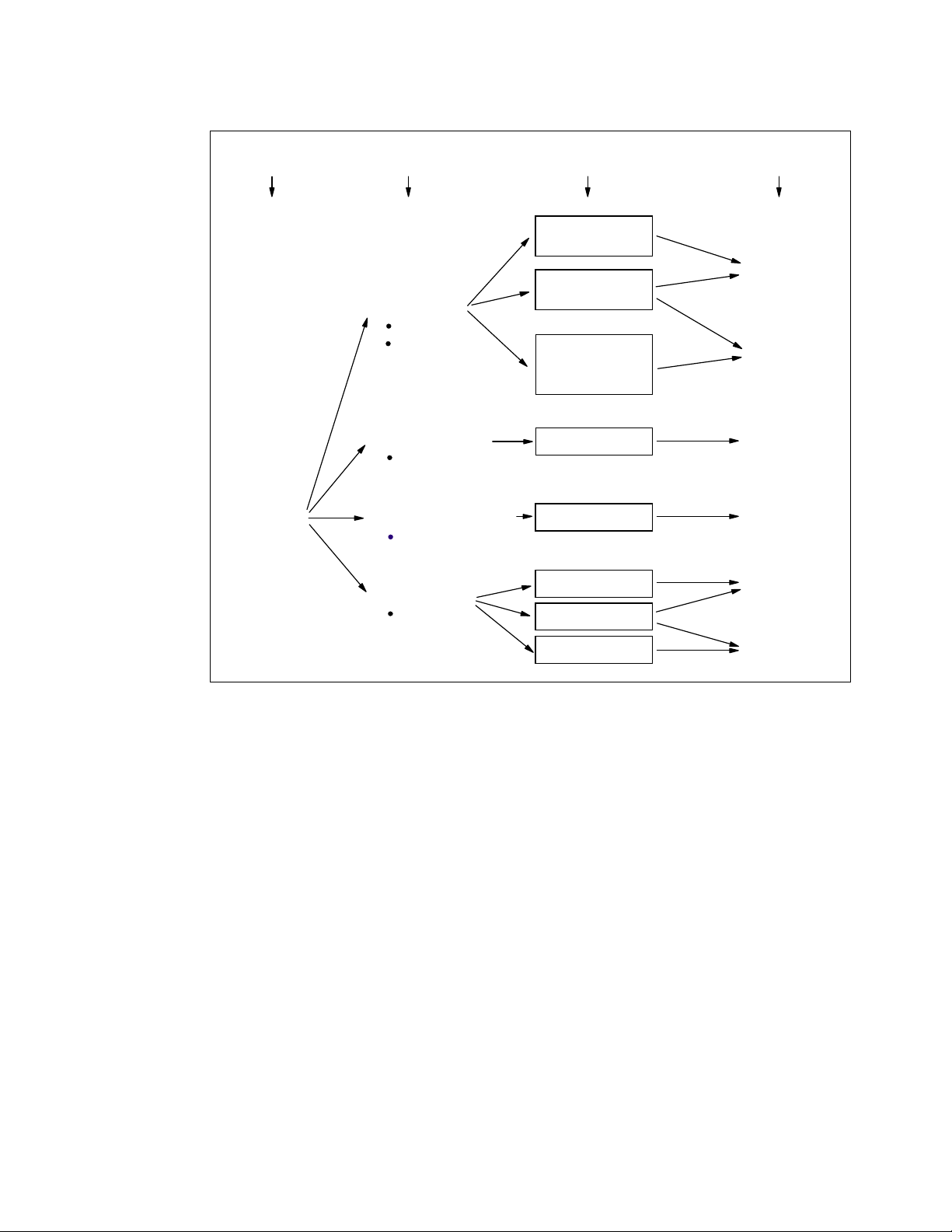
z990
Mode
Image
Modes
ESA/390 Mode
CPs
CPs and zAAPs
(z/OS 1.6 and
above only)
ESA/390 TPF Mode
CPs only
Operating
Systems
z/OS
Linux on zSeries
z/VM
OS/390 R10
z/VSE
VSE/ESA
Linux for S/390
TPF
Operating System
Addressing
Modes
64-bit
Architecture
Mode
Option
31-bit
Architecture
Mode
31-bit
Architecture
Mode
Logically
Partitioned
Mode
Coupling Facility Mode
ICFs and/or CPs
Linux Only Mode
IFLs or CPs
CFCC
Linux on zSeries
z/VM
Linux for S/390
Operating System
Option
64-bit
Architecture
Mode
64-bit
Architecture
Mode
31-bit
Architecture
Mode
Figure 2-15 z990 Modes of operation diagram
Logical Partitioning overview
Logical Partitioning is a function implemented by the Processor Resource/Systems Manager
(PR/SM), available on all z990 servers.
The z990 only runs in LPAR mode. This means that virtually all system aspects are now
controlled by PR/SM functions.
PR/SM is very much aware of the book structure introduced on the z990. However, logical
partitions do not have this awareness. Logical partitions have resources allocated to them
coming from a variety of physical resources, and have no control over these physical
resources from a systems standpoint—but the PR/SM functions do have.
PR/SM manages and optimizes allocation and dispatching work on the physical topology.
Most physical topology knowledge that was previously handled to the operating systems is
now the responsibility of PR/SM.
PR/SM always attempts to allocate all real storage for a logical partition within one book, and
attempts to dispatch a logical PU on a physical PU in a book that also has the central storage
for that logical partition. If not possible, a PU in an adjacent book is chosen. In general,
PR/SM tries to minimize the number of books required to allocate the resources of a given
logical partition. In addition, PR/SM always tries to re-dispatch a logical PU on the same
physical PU to assure that as much as possible of the L1 cache content can be reused.
Chapter 2. System structure and design 57
Page 70

PR/SM enables z990 servers to be initialized for logically partitioned operation, supporting up
to 30 logical partitions. Each logical partition can run its own operating system image in any
image mode, independently from the other logical partitions.
A logical partition can be activated or deactivated at any time, but changing the number of
defined logical partitions is disruptive, as it requires a Power-on Reset (POR). Some facilities
may not be available to all operating systems, as they may have software corequisites.
Each logical partition has the same resources as a “real” CPC, which are:
Processor(s)
Called
be
can be defined to provide the required level of processor resources to a logical partition.
Also, the
acquiring more than its defined weight, limiting its processor consumption.
For z/OS Workload License Charge (WLC), a logical partition “Defined Capacity” can be
set, enabling the
ESA/390 mode logical partitions can have CPs and zAAPs logical processors. Both logical
processor types can be defined as either all dedicated or all shared. The zAAP support is
planned to be introduced by z/OS 1.6.
Only Coupling Facility (CF) partitions can have both dedicated
processors defined.
Figure 2-16 on page 59 shows the logical processor assignment screen of the Customize
Image Profile on the Hardware Management Console (HCM), for an ESA/390 mode
image. This panel allows the definition of:
– Dedicated or shared logical processors, including CPs and zAAPs (remember that
– The initial weight, optional capping, and Workload Manager options for shared CPs (a
– The number of initial and optional reserved processors (CPs)
Logical Processor(s), they can be defined as CPs, IFLs, ICFs, or zAAPs. They can
dedicated to a partition or shared between partitions. When shared, a processor weight
capping option can be turned on, which prevents a logical partition from
soft capping function.
and shared logical
zAAPs initially appear as “Integrated Facility for Applications” on HCM panels)
shared zAAP’s weight equals a CP’s weight, but share calculation is based on the sum
of ICFs’, IFLs’ and zAAPs’ weights)
– The optional number of initial and reserved integrated facility for application (zAAPs)
58 IBM ^ zSeries 990 Technical Guide
Page 71

Figure 2-16 Logical processor assignment (HMC- Image Profile)
On the z990, the sum of defined and reserved logical processors for an ESA/390 mode
logical partition is limited to 32. However, z/OS 1.6 and z/VM 5.1 operating systems are
planned to support up to 24 processors. For z/OS, the 24 processors limit applies to the
sum of CPs and zAAPs logical processors. The weight and the number of online logical
processors of a logical partition can be dynamically managed by the LPAR CPU
Management function of the Intelligent Resource Director, to achieve the defined goals of
this specific partition and of the overall system.
Memory
Memory, either Central Storage or Expanded Storage, must be dedicated to a logical
partition. The defined storage(s) must be available during the logical partition activation;
otherwise, the activation fails.
Reserved storage can be defined to a logical partition, enabling non-disruptive memory
add to and removal from a logical partition, using the LPAR Dynamic Storage
Reconfiguration. Refer to 2.2.11, “LPAR Dynamic Storage Reconfiguration (DSR)” on
page 71 for more information.
Channels
Channels can be shared between logical partitions by including the partition name in the
partition list of a Channel Path ID (CHPID). I/O configurations are defined by the I/O
Configuration Program (IOCP) or the Hardware Configuration Dialog (HCD) in conjunction
with the CHPID Mapping Tool (CMT). The CMT is an optional, but strongly recommended,
tool used to map CHPIDs onto Physical Channel IDs (PCHIDs) that represent the physical
location of a port on a card in an I/O cage.
Chapter 2. System structure and design 59
Page 72

IOCP is available on the z/OS, OS/390, z/VM, VM/ESA, z/VSE, and VSE/ESA operating
systems, and as a stand-alone program on the z990 hardware console. HCD is available
on z/OS, z/VM, and OS/390 operating systems.
ESCON channels (CHPID type CNC or FCV) can be
Management (DCM) function of the Intelligent Resource Director. DCM enables the
system to respond to ever-changing channel requirements by moving channels from
lesser-used control units to more heavily used control units, as needed.
managed by the Dynamic CHPID
Logically partitioned mode
The z990 server can only run in LPAR Mode; up to 30 logical partitions can be defined on any
z990 server. A logical partition can be defined to operate in one of the following image modes:
ESA/390 mode, to run:
– A z/Architecture operating system image, on dedicated
– An ESA/390 operating system image, on dedicated
– A Linux operating system image, on dedicated
– A z/OS 1.6 or later operating system image, on any of the following:
• Dedicated
• Dedicated CPs
• Shared CPs
Note: zAAPs can be defined to any ESA/390 mode image (see Figure 2-16 on
page 59). However, zAAPs are supported only by z/OS 1.6 and later operating
systems. Any other operating system cannot use zAAPs, even if they are defined to the
logical partition. zAAPs are not supported for a z/OS guest under z/VM.
or shared CPs
and dedicated zAAPs
and shared zAAPs
or shared CPs
or shared CPs
or shared CPs
ESA/390 TPF mode, to run:
– A TPF operating system image, only on dedicated
Coupling Facility mode, to run a CF image, by loading the CFCC into this logical partition.
The CF image can run any of the following definitions:
• Dedicated
• Dedicated
• Dedicated
• ICFs dedicated
Linux-only mode, to run:
– A Linux operating system image, on either:
• Dedicated
• Dedicated
– A z/VM operating system image, on either:
• Dedicated
• Dedicated
Table 2-4 on page 61 shows all LPAR modes, required characterized PUs, and operating
systems, and which PU characterizations can be configured to a logical partition image. The
available combinations of dedicated (DED) and shared (SHR) processors are also shown. For
or shared CPs
or shared ICFs
and shared ICFs
and CPs shared
or shared IFLs
or shared CPs
or shared IFLs
or shared CPs
or shared CPs
60 IBM ^ zSeries 990 Technical Guide
Page 73

all combinations, an image can also have Reserved Processors defined, allowing
non-disruptive image upgrades.
Table 2-4 LPAR mode and PU usage
LPAR mode PU type Operating systems PUs usage
ESA/390 CPs z/Architecture operating systems
ESA/390 operating systems
Linux
CPs
and
zAAPs
ESA/390 TPF CPs TPF CPs DED
Coupling
Facility
Linux Only IFLs
ICFs
and/or
CPs
or
CPs
z/OS (1.6 and later) CPs DED and zAAPs DED, or
CFCC ICFs DED
Linux
z/VM
CPs DED
CPs SHR and zAAPs SHR
or CPs SHR
or CPs SHR
or ICFs SHR, or
CPs DED or CPs SHR, or
ICFs DED and ICFs SHR, or
ICFs DED and CPs SHR
IFLs DED or IFLs SHR, or
CPs DED or CPs SHR
Dynamic Add/Delete of a logical partition name
The ability to add meaningful logical partition names to the configuration without a Power-On
Reset is being introduced. Prior to this support, extra logical partitions were defined by adding
reserved names in the Input/Output Configuration Data Set (IOCDS), but one may not have
been able to predict what might be meaningful names in advance.
Dynamic add/delete of a logical partition name allows reserved logical partition 'slots' to be
created in an IOCDS in the form of extra Logical Channel Subsystem (CSS), Multiple Image
Facility (MIF) image ID pairs. A reserved partition is defined with the partition name
placeholder ‘
devices. These extra Logical Channel Subsystem MIF image ID pairs (CSSID/MIFID) can be
later assigned an logical partition name for use (or later removed) via dynamic I/O commands
using the Hardware Configuration Definition (HCD). The IOCDS still must have the extra I/O
slots defined in advance since many structures are built based upon these major I/O control
blocks in the Hardware System Area (HSA). This support is exclusive to the z990 and z890
and is applicable to z/OS V1.6, which is planned to be available in September 2004.
* ’, and cannot be assigned to an access or candidate list of channel paths or
When a logical partition is renamed, its name can be changed from ’NAME1’ to ‘
changed again from ‘
* ’ to ‘NAME2’; the logical partition number and MIFID are retained
* ’ and then
across the logical partition name change. However, the master keys in PCIXCC that were
associated with the old logical partition ‘NAME1’ are retained. There is no explicit action taken
against a cryptographic component for this.
Attention: Cryptographic cards are not tied to partition numbers or MIFIDs. They are set
up with AP numbers and domain indices. These are assigned to a partition profile of a
given name. The customer assigns these "lanes" to the partitions now and continues to
have responsibility to clear them out if he changes who is using them.
Chapter 2. System structure and design 61
Page 74

2.2.7 Model configurations
The z990 server model nomenclature is based on the number of PUs available for customer
use in each configuration. Four models of the z990 server are available:
IBM 2084 model A08: Eight PUs are available for characterization as CPs, IFLs, ICFs,
zAAPs (up to four), or additional SAPs.
IBM 2084 model B16: 16 PUs are available for characterization as CPs, IFLs, ICFs, zAAPs
(up to eight), or additional SAPs.
IBM 2084 model C24: 24 PUs are available for characterization as CPs, IFLs, ICFs,
zAAPs (up to 12), or additional SAPs.
IBM 2084 model D32: 32 PUs are available for characterization as CPs, IFLs, ICFs,
zAAPs (up to 16), or additional SAPs.
When a z990 order is configured, PUs are selected according to their intended usage. They
can be ordered as:
CP The Processor Unit purchased and activated supporting the z/OS,
Unassigned CP A Central Processor purchased for future use as a CP. It is offline and
IFL The Integrated Facility for Linux (IFL) is a Processor Unit that is
Unassigned IFL A Processor Unit purchased for future use as an IFL. It is offline and
OS/390, z/VSE, VSE/ESA, z/VM, and Linux operating systems, which
can also run the Coupling Facility Control Code (CFCC).
unavailable for use.
purchased and activated for exclusive use by the z/VM and Linux
operating systems.
unavailable for use.
ICF A Processor Unit purchased and activated for exclusive use by the
Coupling Facility Control Code (CFCC).
zAAP A Processor Unit purchased and activated for exclusive use to run
Java code under control of z/OS JVM.
Additional SAP The Optional System Assist Processor (SAP) is a Processor Unit that
is purchased and activated for use as a SAP.
Unassigned CPs are purchased PUs with the intention to be used as CPs, and usually have
this status for software charging reasons. Unassigned CPs do not count in establishing the
MSU value to be used for MLC software charging, or when charged on a per Processor Unit
basis.
Unassigned IFLs are purchased IFLs with the intention to be used as IFLs, and usually have
this status for software charging reasons. Unassigned IFLs do not count in establishing the
charge for either z/VM or Linux.
This method prevents RPQ handling in case a temporary downgrade is required. When the
capacity need arises, the unassigned CPs and IFLs can be assigned nondisruptively.
Upgrades
Concurrent CP, IFL, ICF, or zAAP upgrades are done within a z990 model. Concurrent
upgrades require PU spares. PU spares are PUs that are
each MCM and are not characterized as a CP, IFL, ICF, zAAP, or SAP.
not the two standard spares on
62 IBM ^ zSeries 990 Technical Guide
Page 75

If the upgrade request cannot be accomplished within the given model, a model upgrade is
required. A model upgrade will cause the addition of one or more books to accommodate the
desired capacity. Additional books can be installed concurrently.
Upgrades from one IBM 2084 model to another are concurrent and mean that one or more
books are added. Table 2-5 shows the possible model upgrades within the IBM 2084 model
range.
Table 2-5 z990 upgrade paths
z990 Models 2084-A08 2084-B16 2084-C24 2084-D32
2084-A08 - X X X
2084-B16 - - X X
2084-C24 - - - X
2084-D32----
Upgrade paths from IBM 2064 models (z900) offer a virtually unrestricted upgrade capability.
Upgrades from any z900 to any z990 server are supported (with the exception of the IBM
2064 model 100, which can only can be upgraded to another z900 model).There are also no
upgrade paths from IBM 9672 G5 and G6 models, nor is there an upgrade path from the IBM
2066 models (z800).
There are limited upgrade paths from the 2086-A04 model (z890) to the 2084-A08 model
(z990). For details, contact your IBM representative or IBM Business Partner.
Figure 2-17 shows all upgrade paths from z900 to z990 models, and all upgrade paths within
the z990 model range.
z900 z990
100
101-109
1C1-116
2C1-216
A08
B16
C24
D32
Figure 2-17 Supported z900-to-z990 upgrade paths
Software models
In order to recognize how many PUs are characterized as a CP, the STSI instruction returns a
value that can be seen as a software model number to determine the number of assigned
CPs. Characterization of a PU as an IFL, an ICF, or an zAAP is not reflected in the output of
the STSI instruction, since they have no effect on MLC software charging.
Chapter 2. System structure and design 63
Page 76

Table 2-6 shows that regardless of the number of books, a configuration with one
characterized CP is possible (for example, an IBM 2084 model D32 may have only one PU
characterized as a CP for customer use).
Table 2-6 z990 software models
z990 Models Software Models
IBM 2084-A08 301 - 308
IBM 2084-B16 301 - 316
IBM 2084-C24 301 - 324
IBM 2084-D32 301 - 332
Note: Software model number 300 is used for IFL or ICF only models.
This structure enables a different approach to downgrading the system in cases where a
larger system is installed on which, for software charging reasons, temporarily less CP
capacity must be assigned. It is now possible (with the use of the IBM internal e-Config tool)
to order a simultaneous downgrade.
Consider, for example, an IBM 2084-A08 ordered with six PUs for customer use. Feature
code (F/C 0716) specifies the number of PUs characterized as CPs (assume four), and a
different feature code (F/C 1716) specifies the number of unassigned CPs (assume two). The
unassigned CPs are part of the order, but cannot be used and will not be charged for MLC
software charges. Later, when the capacity need requires it, the unassigned CPs can be
assigned and will become active assigned CPs.
An unassigned CP is a PU that is purchased as a CP, but is not active in the model
configuration. An unassigned IFL is a PU that is purchased as an IFL, but is not active in the
current model configuration.
A minimum of one PU characterized as a CP, IFL, or ICF is required per system. PUs can be
characterized as CPs, IFLs, ICFs, or zAAPs. The maximum number of CPs is 32, the
maximum number of IFLs is 32, the maximum number of ICFs is 16, and the maximum
number of zAAPs amounts to 16 (up to four zAAPs per book). Not all PUs available on a
model are required to be characterized as a CP, IFL, ICF, or zAAP. Only purchased PUs are
identified by a feature code.
Feature codes related to CPs and unassigned CPs, IFLs and unassigned IFLs, ICFs, SAPs,
and zAAPs are:
Feature code 0716 for a CP
Feature code 1716 for an unassigned CP
Feature code 0516 for an IFL
Feature code 0517 for an unassigned IFL
Feature code 0518 for an ICF
Feature code 0519 for an optional SAP
Feature code 0520 for a zAAP
PU conversions
Assigned CPs, unassigned CPs, assigned IFLs, unassigned IFLs, and ICFs may be
converted to other assigned, or unassigned feature codes. Valid conversion paths are:
Conversion of feature code 0716 to 1716, 0516 or 0518 for conversion of a CP to an
unassigned CP, an IFL, or an ICF
64 IBM ^ zSeries 990 Technical Guide
Page 77

Conversion of feature code 1716 to 0716, for conversion of an unassigned CP to a CP
Conversion of feature code 0516 to 0517, 0518 or 0716, for conversion of an IFL to an
unassigned IFL, an ICF, or a CP
Conversion of feature code 0517 to 0516, for conversion of an unassigned IFL to an IFL
Conversion of feature code 0518 to 0516 or 0716, for conversion of an ICF to an IFL or a
CP
All listed conversions are usually non-disruptive. In exceptional cases the conversion may be
disruptive, for example, when an IBM 2084 model A08 with eight CPs is converted to an all
IFL system. In addition, LPAR disruption may occur when PUs must be freed before they can
be converted.
This information is also summarized in Table 2-7.
Table 2-7 PU conversions
To
CP
From
CP (0716) - Ye s Ye s No Ye s
(0716)
Unassigned
CP (1716)
IFL
(0516)
Unassigned
IFL (0517)
ICF
(0518)
Unassigned - CP (1716)
IFL (0516)
Unassigned IFL (0517)
ICF (0518)
Yes - No No No
Ye s N o - Ye s Ye s
No No Yes - No
Ye s N o Ye s N o -
Capacity Backup (CBU)
CBUs deliver temporary capacity (feature code 7800) on top of what a customer might have
installed in numbers of assigned CPs, IFLs, ICFs, zAAPs and additional SAPs. The total
number of active PUs (the sum of all assigned CPs, IFLs, ICFs, zAAPs, and additional SAPs)
plus the number of CBUs cannot exceed the total number of PUs available on the MCMs in all
books.
To determine the number of CBUs that can be added to a given configuration, some rules
must be considered:
The number of assigned CPs + IFLs + ICFs + zAAPs + additional SAPs + CBUs equals
less than 8 on an IBM 2084-A08.
The number of assigned CPs + IFLs + ICFs + zAAPs + additional SAPs + CBUs equals
less than 16 on an IBM 2084-B16.
The number of assigned CPs + IFLs + ICFs + zAAPs + additional SAPs + CBUs equals
less than 24 on an IBM 3084-C24.
The number of assigned CPs + IFLs + ICFs + zAAPs + additional SAPs + CBUs equals
less than 32 on an IBM 3084-D32.
Unassigned CPs and IFLs are ignored. In fact, they are considered spares and are available
for use as a CBU. When an unassigned CP or IFL is converted into an assigned CP or IFL, or
when additional PUs are characterized as CPs or IFLs, then the number of CBUs that can be
activated is decreased.
Chapter 2. System structure and design 65
Page 78

Software model MSU values
All software models have an MSU value that is used the determine the software license
charge for all MLC software. Table 2-8 on page 66 shows all MSU values for all software
models.
The Mainframe Charter, announced in August 2003, offers lower software charges for
selected IBM software on z990. This price/performance improvement is achieved by lowering
the original established MSU value for each software model by approximately 10%, resulting
in a list of software MSU values (Pricing MSUs) to be used for software charging.
Table 2-8 Software model MSU values
Software model MSU/ Pricing MSU Software model MSU/ Pricing MSU
301 77/70 317 886/799
302
303
304
305
306
307
308
309
310
311
312
313
314
315
316
147/132 318 927/837
213/191 319 973/878
277/248 320 1018/919
337302 321 1062/959
395/352 322 1106/999
451/402 323 1149/1037
503/448 324 1192/1076
551/492 325 1234/1114
601/538 326 1276/1151
647580 327 1317/1188
691/620 328 1358/1225
733/661 329 1398/1261
772/696 330 1436/1296
810/730 331 1474/1332
844/761 332 1512/1365
Hardware Management Console and Support Elements
All z990 models include a Hardware Management Console (HMC) and two internal Support
Elements (SEs) that are located in the Z frame.
On z990 servers, the Hardware Management Console provides the platform and user
interface that can control and monitor the status of the system. The SEs are basically used by
IBM service representatives.
Up to four Hardware Management Consoles can be ordered per z990 server, providing more
flexibility and additional points of control. The Hardware Management Console can also
provide a single point of control and single system image for a number of CPCs configured to
it.
The internal SEs for each CPC are attached by local area network (LAN) to the Hardware
Management Console, and allow the Hardware Management Console to monitor the CPC by
providing status information. Each internal SE provides the Hardware Management Console
66 IBM ^ zSeries 990 Technical Guide
Page 79

with operator controls for its associated CPC, so you can target operations in parallel to
multiple or all CPCs, or to a single CPC.
The second SE, called Alternate SE, is standard on all z990 models and serves as a backup
to the primary SE. Error detection and automatic switch-over between the two redundant SEs
provides enhanced reliability and availability. There are also two fully redundant interfaces,
known as the Power Service Control Network (PSCN), between the two SEs and the CPC.
Note: The z990 (and the z890) are the last zSeries servers offering Token Ring adapters
on the Hardware Management Consoles and Support Elements. Timely planning is
advised in preparation of migration to the Ethernet environment.
Note: Hardware Management Consoles are to become closed platforms with the next
zSeries server and will only support the HMC application. Other applications, such as for
the IBM ESCON Director and the IBM Sysplex Timer, will no longer be supported from the
HMC. Timely planning for needed console equipment for Directors and Timers is
recommended. When available, these HMCs can only communicate with Generation 5
servers and later (Multiprise® 3000, G5, G6, z800, z900, z890, z990) and TCP/IP will be
the only communication protocol supported.
For further information on the Hardware Management Console and SEs, refer to Appendix A,
“Hardware Management Console (HMC)” on page 235.
Dual External Time Reference
The z990 implements a dual External Time Reference (ETR). The optional ETR cards
provide the interface to the IBM Sysplex Timers, which are used for timing synchronization
between systems in a Sysplex environment.
If z990 models have coupling links, then two ETR cards with dual paths to each book are
installed, allowing continued operation even if a single ETR card fails. This redundant design
also allows concurrent maintenance.
2.2.8 Storage operations
In z990 servers, memory can be assigned as a combination of central storage and expanded
storage, supporting up to 30 logical partitions.
Before you activate a logical partition, central storage (and optional expanded storage) must
be defined to the logical partition. All installed storage can be configured as central storage.
Each individual logical partition can be defined with a maximum of 128 GB of central storage.
Central storage can be dynamically assigned to expanded storage and back to central
storage as needed, without a Power-on Reset (POR) (refer to “LPAR single storage pool” on
page 55 for further details).
Memory
resources for z/Architecture and ESA/390 Architecture mode logical partitions running
operating systems that support Dynamic Storage Reconfiguration (DSR) (refer to 2.2.11,
“LPAR Dynamic Storage Reconfiguration (DSR)” on page 71 for further details).
cannot be shared between system images. You can dynamically reallocate storage
Operating systems running under z/VM can exploit the z/VM capability of implementing virtual
memory to guest virtual machines. The z/VM dedicated
guest operating systems’ memories.
real storage can be “shared” between
Chapter 2. System structure and design 67
Page 80

Figure 2-18 shows the z990 modes and memory diagram, summarizing all image modes,
with their processor types and the Central Storage (CS) and Expanded Storage (ES)
definitions allowed for each mode.
z990
Mode
Logically
Partitioned
Mode
Image
Modes
ESA/390 Mode
CPs
CPs and zAAPs
ESA/390 TPF Mode
CPs only
Coupling Facility Mode
ICFs and/or CPs
Linux Only Mode
IFLs or CPs
Definable Central Storage (CS)
and Expanded Storage
CS < = 128 GB
ES = Yes
CS < = 128 GB
ES = Yes
CS < = 128 GB
ES = No
CS < = 128 GB
ES = Yes
Figure 2-18 Modes and memory diagram
Table 2-9 shows the z990 storage allocation and usage possibilities, which depend upon the
image and architecture modes.
Table 2-9 Storage definition and usage possibilities
Image mode Architecture mode
Maximum central storage Expanded storage
(addressability)
Architecture z990
definition
z990
definable
Operating
system usage
ESA/390 z/Architecture (64-bit) 16 EB 128 GB yes only by z/VM
ESA/390 (31-bit) 2 GB 128 GB yes yes
ESA/390 TPF ESA/390 (31-bit) 2 GB 128 GB yes yes
Coupling Facility CFCC (64-bit) 16 EB 128 GB no no
Linux Only z/Architecture (64-bit) 16 EB 128 GB yes
only by z/VM
ESA/390 (31-bit) 2 GB 128 GB yes yes
Remember that either a z/Architecture mode or an ESA/390 architecture mode operating
system can run in an ESA/390 image mode on a z990. Any ESA/390 image can be defined
with more than 2 GB of central storage
and can have expanded storage. These options allow
you to configure more storage resources than the operating system is capable of addressing.
ESA/390 mode
In ESA/390 mode, storage addressing can be 31- or 64-bits, depending on the operating
system architecture
and the operating system configuration.
68 IBM ^ zSeries 990 Technical Guide
Page 81

An ESA/390 mode image is always initiated in 31-bit addressing mode. During its
initialization, a z/Architecture operating system can change it to 64-bit addressing mode and
operate in the z/Architecture mode.
Some z/Architecture operating systems, like z/OS, will
and operate in 64-bit mode. The z/OS Bimodal Migration Accommodation Offering allows for
a limited amount of time to run z/OS in 31-bit mode. This offering provides fallback support to
31-bit mode in the event it is required during migration to z/OS in 64-bit mode. Beginning with
z/OS V1.5, the z/OS Bimodal Migration Accommodation Offering is no longer available.
Other z/Architecture operating systems, like the z/VM and the OS/390 Version 2 Release 10,
can be configured to change to 64-bit mode or to stay in 31-bit mode and operate in the
ESA/390 architecture mode.
always change this addressing mode
z/Architecture mode
In z/Architecture mode, storage addressing is 64-bit, allowing for an addressing range of up to
16 exabytes (16 EB). The 64-bit architecture allows a maximum of 16 EB to be used as
central storage. However, the current z990 definition limit for logical partitions is 128 GB of
central storage.
Expanded storage
z/Architecture mode. However, only z/VM is able to use expanded storage. Any other
operating system running in z/Architecture mode (like a z/OS or a Linux for zSeries image)
can also be configured to an image running an operating system in
will not address the configured expanded storage. This expanded storage remains
configured to this image and is
unused.
ESA/390 architecture mode
In ESA/390 architecture mode, storage addressing is 31-bit, allowing for an addressing range
of up to 2 GB. A maximum of 2 GB can be used for central storage. Since the processor
storage can be configured as central and expanded storage, memory above 2 GB may be
configured as expanded storage. In addition, this mode permits the use of either 24-bit or
31-bit addressing, under program control, and permits existing application programs to run
with existing control programs.
Since an ESA/390 mode image can be defined with up to 128 GB of central storage, the
central storage above 2 GB will
not be used, but remains configured to this image.
ESA/390 TPF mode
In ESA/390 TPF mode, storage addressing follows the ESA/390 architecture mode, to run the
TPF/ESA operating system in the 31-bit addressing mode.
Coupling Facility mode
In Coupling Facility mode, storage addressing is 64-bit for a Coupling Facility image running
CFLEVEL 12 or above, allowing for an addressing range up to 16 EB. However, the current
z990 definition limit for logical partitions is 128 GB of storage.
Expanded storage cannot be defined for a Coupling Facility image.
Only IBM Coupling Facility Control Code can run in Coupling Facility mode.
Linux Only mode
In Linux Only mode, storage addressing can be 31- or 64-bit, depending on the operating
system architecture
ESA/390 mode.
and the operating system configuration, in exactly the same way as in
Chapter 2. System structure and design 69
Page 82

Only Linux and z/VM operating systems can run in Linux Only mode:
Linux for zSeries uses 64-bit addressing and operates in the z/Architecture mode.
Linux for S/390 uses 31-bit addressing and operates in the ESA/390 Architecture mode.
z/VM can be configured to use 64-bit addressing and operate in the z/Architecture mode,
or to use 31-bit addressing and operate in the ESA/390 architecture mode.
2.2.9 Reserved storage
Reserved storage can optionally be defined to a logical partition allowing a non-disruptive
image memory upgrade for this partition. Reserved storage can be defined to both central
and expanded storage, and to any image mode except the Coupling Facility mode.
A logical partition must define an amount of central storage and, optionally (if not a Coupling
Facility image), an amount of expanded storage. Both central and expanded storages can
have two storage sizes defined: an initial value and a reserved value:
The initial value is the storage size allocated to the partition when it is activated.
The reserved value is an additional storage capacity beyond its initial storage size that a
logical partition can acquire dynamically. The reserved storage sizes defined to a logical
partition do not have to be available when the partition is activated. They are just
predefined storage sizes to allow a storage increase from the logical partition point of view.
Without the reserved storage definition, a logical partition storage upgrade is disruptive,
requiring:
Partition deactivation
An initial storage size definition change
Partition activation
The additional storage capacity to a logical partition upgrade can come from:
Any unused available storage
Another partition that has released some storage
A concurrent CPC memory upgrade
A concurrent logical partition storage upgrade uses Dynamic Storage Reconfiguration (DSR)
and the operating system must use the Reconfigurable Storage Units (RSUs) definition to be
able to add or remove storage units. Currently, only z/OS and OS/390 operating systems have
this support.
2.2.10 LPAR storage granularity
Storage granularity for Central Storage and Expanded Storage in LPAR mode varies as a
function of the total installed storage, as shown in Table 2-10 on page 71.
This information is required for Logical Partition Image setup and for z/OS and OS/390
Reconfigurable Storage Units definition.
70 IBM ^ zSeries 990 Technical Guide
Page 83

Table 2-10 LPAR storage granularity
Total installed memory Partition storage granularity (CS and ES)
Installed memory <= 32 GB 64 MB
32 GB < Installed memory <= 64 GB 128 MB
64 GB < Installed memory <= 128 GB 256 MB
128 GB < Installed memory <= 256 GB 512 MB
Remember that logical partitions are currently limited to a maximum size of 128 GB of
storage.
2.2.11 LPAR Dynamic Storage Reconfiguration (DSR)
Dynamic Storage Reconfiguration (DSR) on z990 servers allows an operating system running
in a logical partition to add (non-disruptively) its reserved storage amount to its configuration,
if any unused storage exists. This unused storage can be obtained when another logical
partition releases some storage, or when a concurrent memory upgrade takes place.
With enhanced DSR, the unused storage does not have to be continuous.
When an operating system running in a logical partition assigns a storage increment to its
configuration, PR/SM will check if there are any free storage increments and will dynamically
bring the storage online.
PR/SM will dynamically take offline a storage increment and will make it available to other
partitions when an operating system running in a logical partition releases a storage
increment.
2.2.12 I/O subsystem
All models have one I/O subsystem. The I/O subsystem should be considered as the physical
entity that encompasses all control functions and all connections to all devices.
The z990 I/O subsystem provides great flexibility and high availability and performance,
allowing:
High bandwidth
The z990 I/O subsystem can handle up to 96 GBps; this is four times the z900 server’s
bandwidth. Individual channels can have up to 2 GBps data rates.
Wide connectivity
A z990 server can be connected to an extensive range of interfaces, using protocols such
as Fibre Channel Protocol (FCP) for Small Computer System Interface (SCSI), Gigabit
Ethernet (GbE), Fast Ethernet (FENET), 1000Base-T Ethernet, and High Speed Token
Ring, along with FICON, ESCON, and coupling link channels.
Concurrent channel upgrades
It is possible to concurrently add channels to a z990 server provided there are unused
channel positions in an I/O cage. Additional I/O cages can be previously installed on an
initial configuration via Plan Ahead, to provide greater capacity for concurrent upgrades.
This capability may help eliminate an outage to upgrade the channel configuration. For
more information about concurrent channel upgrades, see “CUoD for I/O” on page 195.
Chapter 2. System structure and design 71
Page 84

Dynamic I/O reconfiguration
Dynamic I/O reconfiguration enhances system availability by supporting the dynamic
addition, removal, or modification of channel paths, control units, I/O devices, and I/O
configuration definitions to both hardware and software (if it has this support), without
requiring a planned outage.
ESCON port sparing and upgrading
The ESCON 16-port I/O card includes one unused port dedicated for sparing in the event
of a port failure on that card. Other unused ports are available for growth of ESCON
channels without requiring new hardware, enabling concurrent upgrades via Licensed
Internal Code.
For detailed information about the I/O system structure, see Chapter 3, “I/O system structure”
on page 73.
2.2.13 Channel Subsystem
The representation of all connections and devices is called the Channel Subsystem. The
z990 introduces the concept of Multiple Logical Channel Subsystems. Up to two Logical
Channel Subsystems (LCSSs) can be defined in the IOCDS, and this allows for the definition
of up to 512 channels. One IOCDS describes the complete I/O configuration and one HSA
after Power-On Reset (POR). The HSA is always located in the physical memory of Book 0.
Logical Channel Subsystem (LCSS)
A Logical Channel Subsystem (LCSS) is a logical collection of up to 256 CHPIDs that are
mapped to physical channels with the assistance of HCD, the Channel Mapping Tool (CMT),
and IOCP. Physical channels are represented in the system by Physical Channel IDs
(PCHIDs). The z990 supports up to two LCSSs (512 CHPIDs), but the Multiple CSS
architecture allows for more LCSSs.
Physical Channel ID (PCHID)
PCHIDs identify the physical ports on cards located in I/O cages and follow the numbering
scheme listed in Table 2-11.
Table 2-11 PCHID locations
Cage Front PCHID ## Rear PCHID ##
I/O Cage 1 100 - 1FF 200 - 2FF
I/O Cage 2 300 - 3FF 400 - 4FF
I/O Cage 3 500 - 5FF 600 - 6FF
CEC Cage 000 - 0FF reserved for ICB-4
Introduction of PCHIDs means that CHPIDs are no longer pre-assigned. It is the responsibility
of the user to assign the CHPID numbers through the use of HCD/IOCP, and the CHPID
mapping tool. Assigning a CHPID means that the CHPID number is associated with a
physical channel port location (PCHID) and an LCSS (LCSS0 or LCSS1). CHPID numbers
still range from 00 to FF and must be unique within an LCSS.
For more detailed information about the Logical Channel Subsystem structure, see 4.1.1,
“Logical Channel Subsystem structure” on page 110.
72 IBM ^ zSeries 990 Technical Guide
Page 85

Chapter 3. I/O system structure
This chapter describes the I/O system structure, the connectivity and the cryptographic
options available on the zSeries 990 server.
The z990 server I/O and cryptographic features are also discussed, including configuration
options for each feature.
The following topics are included:
3.1, “Overview” on page 74
3.2, “I/O cages” on page 75
3
3.3, “I/O and cryptographic feature cards” on page 84
3.4, “Connectivity” on page 89
© Copyright IBM Corp. 2003, 2004. All rights reserved. 73
Page 86

3.1 Overview
The z990 I/O system design provides great flexibility, high availability and performance,
allowing:
High bandwidth
The z990 I/O system can handle up to 96 GBps, which is four times the z900 server’s
bandwidth. Individual channels can have up to 2 GBps and individual Coupling Facility links
up to 2 GBps data rates.
Wide connectivity
A z990 server can be connected to an extensive range of interfaces, using protocols such as
Fibre Channel Protocol (FCP) for Small Computer System Interface (SCSI), Gigabit Ethernet
(GbE), 1000BASE-T Ethernet, 100BASE-T Ethernet, 10BASE-T Ethernet, Token Ring along
with FICON Express, ESCON, and coupling links channels.
Cryptographic functions
The z990 I/O system also supports optional cryptographic cards to complement the standard
CP Assist for Cryptographic Function (CPACF) that is implemented in every PU, enhancing
the performance of cryptographic processing.
Concurrent I/O upgrades
It is possible to concurrently add I/O cards to a z990 server provided there are unused slot
positions in an I/O cage. Additional I/O cages can be previously installed on an initial
configuration, via CUoD, to provide greater capacity for concurrent upgrades. This capability
may help eliminate an outage to upgrade the I/O configuration. See more information about
concurrent upgrades on Chapter 8, “Capacity upgrades” on page 187.
Dynamic I/O configuration
Dynamic I/O configuration enhances system availability by supporting the dynamic addition,
removal, or modification of channel paths, control units, I/O devices, and I/O configuration
definitions to both hardware and software (if it has this support) without requiring a planned
outage.
ESCON port sparing and upgrading
The ESCON 16-port I/O card includes one unused port dedicated for sparing in the event of a
port failure on that card. Other unused ports are available for growth of ESCON channels
without requiring new hardware, enabling concurrent upgrades via Licensed Internal Code
(LIC).
The following I/O feature
Up to 1024 ESCON (up to 720 ESCON on model A08)
Up to 120 Fibre Connection (FICON) Express (up to 96 FICON on model A08)
Up to 48 Open Systems Adapter (OSA) Express
Up to 16 Integrated Cluster Bus-4 (ICB-4) (up to 12 ICB-4 on model A08)
Up to 16 Integrated Cluster Bus-3 (ICB-3)
Up to eight Integrated Cluster Bus-2 (ICB-2)
Up to 48 Inter-System Channel-3 (ISC-3) in peer mode (up to 32 ISC-3 in compatibility
mode)
ports are supported in the zSeries 990 server:
Up to two External Time Reference (ETR)
74 IBM ^ zSeries 990 Technical Guide
Page 87

Note: The maximum number of Coupling Links combined (IC, ICB-2, ICB-3, ICB-4, and
active ISC-3 links) cannot exceed 64 per z990 server.
The following cryptographic feature cards are supported in the zSeries 990 server:
Up to four Peripheral Component Interconnect X Cryptographic Coprocessor (PCIXCC)
Up to 12 Peripheral Component Interconnect Cryptographic Accelerator (PCICA)
All z990 servers have two frames. The A frame holds the CEC cage on top and one I/O cage
on the bottom. The Z frame holds up to two optional I/O cages, which may be needed to
accommodate the I/O configuration requirements.
Z Frame
IBF
IBF
BPD
3rd I/O Cage
A Frame
IBF
MRU MRU
CEC Cage
(optional)
MDA MD A
2nd I/O Cage
(optional)
MDA MD A
Figure 3-1 z990 frames and cages
Additional optional I/O cages may be required to install additional I/O and cryptographic cards
during an upgrade. The first optional I/O cage is placed at the bottom of the Z frame, and the
second optional I/O cage is at the top, as shown in Figure 3-1. Although I/O or cryptographic
card installation is concurrent, an I/O cage installation requires an outage.
MDA MDA
MDA
1st I/O Cage
(standard)
MDA
3.2 I/O cages
As mentioned, the z990 server can have up to three I/O cages to house the I/O cards and
cryptographic cards required by a configuration.
Each I/O cage has 28 I/O slots available for I/O cards and cryptographic cards installation and
up to seven I/O domains. Each I/O domain is made up of up to four I/O slots, as shown in
Figure 3-2 on page 76.
Chapter 3. I/O system structure 75
Page 88

Rear of
I/O Cage
36
I/O Domain 6
I/O Slots
29-30-31-32
2 GB-STI 2 GB-STI 2 GB-STI
32
333435
D
D
I
I
C
A
/
C
C
2
I
C
/
/
A
/
O
O
C
G
G
C
1
I
/
/
O
O
G
G
I/O Domain 5
I/O Slots
20-22-25-27
2425262728293031
S
I
I
I
T
/
I
M
(1) (2)
G
/
O
O
F
E
I
/
/
O
O
F
E
I/O Domain 4
I/O Slots
19-21-24-26
22
23
S
I
T
/
I
O
M
E
F
O
F
E
2021
19
I
I
I
/
/
/
O
O
F
E
Board
I
I
/
/
O
O
A
B
23456 98 10111213141516177181
I/O Domain 0
Front of
I/O Cage
Figure 3-2 z990 I/O cage
I/O Slots
1-3-6-8
S
I
I
/
/
O
O
B
A
I
T
/
I
O
M
A
B
O
A
B
I/O Domain 1
I/O Slots
2-4-7-9
I
I
I
I
I
/
/
/
/
/
O
O
O
O
O
A
B
C
D
C
2 GB-STI2 GB-STI2 GB-STI
I/O Domain 2
I/O Slots
10-12-15-17
S
I
I
/
/
O
D
T
I
M
(2)(2)
C
D
I
I
/
/
O
O
C
D
2 GB-STI
I
I
/
/
O
O
C
D
I/O Domain 3
I/O Slots
11-13-16-18
Each I/O domain requires one Self-Timed Interconnect Multiplexer (eSTI-M) card. All I/O
cards within an I/O domain are connected to its eSTI-M card via the back plane board. A full
I/O cage requires seven eSTI-M cards, which are half-high cards, using three and a half slots.
In addition, two Distributed Converter Assembly-Cage Controller (DCA-CC) cards plug into
the I/O cage and the “other half” of slot 28 may be used for a Power Sequence Control (PSC)
card.
If one I/O domain is fully populated with ESCON cards (15 available ports and one spare per
card), up to 60 (four cards x 15 ports) ESCON channels can be installed and used. A fully
populated I/O cage with ESCON cards can have up to 420 (60 x 7 domains) ESCON
channels.
Table 3-1 lists the I/O domain-to-I/O slot relationships within an I/O cage.
Table 3-1 I/O domain-to-I/O slot relationships
Domain I/O slots in domain
0 01, 03, 06, 08
1 02, 04, 07, 09
2 10, 12, 15, 17
3 11, 13, 16, 18
4 19, 21, 24, 26
76 IBM ^ zSeries 990 Technical Guide
Page 89

Domain I/O slots in domain
5 20, 22, 25, 27
6 29, 30, 31, 32
Each eSTI-M card is connected to an STI jack located in a book’s Memory Bus Adapter
(MBA) via an STI cable. As each eSTI-M card requires one STI, up to seven STIs are
required to support one I/O cage. A fully populated three-I/O cage system requires 21 STIs.
IBM selects which slots are used for I/O cards and supplies the appropriate number of I/O
cages and STI cables, either for a new build server or for an existing server upgrade.
Important: Installing an additional I/O cage to an existing z990 server configuration is
disruptive. The Plan Ahead process allows you to avoid this outage by including, in the
initial z990 server order, the number of optional I/O cages required by a future I/O
configuration.
3.2.1 Self-Timed Interconnect (STI)
There are three Memory Bus Adapters (MBAs) on each z990 book. Each MBA has four
Self-Timed Interconnects (STIs), resulting in a total of 12 STIs on each z990 book. Each STI
has a bandwidth of 2 GBps full-duplex, resulting in a maximum bandwidth of 24 GBps per
z990 book.
Depending on the number of books in the configuration, there will be 12, 24, 36, or 48 STIs in
a z990 server, as shown in Table 3-2.
Table 3-2 Number of MBAs and STIs
z990 Model Number of books Number of MBAs Number of STIs
2084-A08 1 3 12
2084-B16 2 6 24
2084-C24 3 9 36
2084-D32 4 12 48
The z990 model D32 has a maximum bandwidth of 96 GBps.
3.2.2 STIs and I/O cage connections
Figure 3-3 on page 78 shows the STI connections from the server’s CEC cage to an I/O cage,
and to an Integrated Cluster Bus-4 (ICB-4) link.
Chapter 3. I/O system structure 77
Page 90

CEC Cage
Book
12 STIs
2 GB/sec
STIs
STI
333 MB/Sec
M
B
A
s
STI
1 GB/Sec
eSTI-M
STI
500 MB/Sec
STI
1 GB/Sec
STI-2 Extender
I/O Cage
ESCON
OSA-E
ISC-3
FICON
Express
STI
333 MB/Sec
STI
1 GB/Sec
eSTI-M
STI
500 MB/Sec
I/O Cards
ESCON
OSA-E
PCIXCC
PCICA
ICB-2
(333 MB/Sec)
STI-3 Extender
ICB-3
(1 GB/Sec)
ICB-4
(2 GB/Sec)
Crypto
Cards
Figure 3-3 STIs and I/O cage connections
A Memory Bus Adapter (MBA) STI connector, located in a book, can be connected to one of
the following:
An eSTI-M card, which creates up to four secondary STI links to connect I/O cards
An STI-2 Extender card, which has up to two ICB-2 links
An STI-3 Extender card, which has up to two ICB-3 links
An ICB-4 link, which attaches directly to an STI port
eSTI-M card
For each z990 I/O cage domain, the MBA-to-I/O card connectivity is achieved using an
eSTI-M card and a 2 GBps STI cable. These half-high eSTI-M cards plug into specific slots
(5, 14, 23, and 28) in the z990 I/O cage. Physical slot locations 5, 14, and 23 house two
half-high eSTI-M cards, while slot 28 has only one half-high card plugged in the top.
The eSTI-M card (Feature Code 0322) takes the 2 GBps link from an MBA’s STI and creates
four secondary STI links, which are connected to the I/O and cryptographic cards through the
I/O cage board. The bandwidth of the secondary link is determined by the feature card it is
attached to:
333 MBps for ESCON
500 MBps for ISC-3
1 Gbps for FICON, OSA-E, PCIXCC and PCICA
78 IBM ^ zSeries 990 Technical Guide
Page 91

Depending on the number of I/O slots plugged into the cage, there may be from one to seven
eSTI-M cards plugged into a z990 I/O cage. The eSTI-M card can be installed or replaced
concurrently.
STI-2 Extender card
The STI-2 Extender card (Feature Code 3992) takes the 2 GBps link from an MBA’s STI and
creates two secondary 333 MBps STI links, which are used to connect ICB-2 links. ICB-2 is
supported only for connection to G5/G6 servers.
The number of STI-2 Extender cards depends on the number of ICB-2 links in a configuration.
Usually, the number of STI-2 Extender cards is half the number of ICB-2 links, but for
availability reasons, two ICB-2 links are connected to two STI-2 Extender cards, each one
having one active ICB-2 link port.
The maximum number of STI-2 Extender cards in a z990 server is four cards, resulting in up
to eight ICB-2 ports. All of them can be installed in a single I/O cage. The STI-2 Extender card
can be installed or replaced concurrently.
STI-3 Extender card
The STI-3 Extender card (Feature Code 3993) takes the 2 GBps link from an MBA’s STI and
creates two secondary 1 GBps STI links, which are used to connect ICB-3 links.
The number of STI-3 Extender cards depends on the number of ICB-3 links in a configuration.
Usually, the number of STI-3 Extender cards is half the number of ICB-3 links, but for
availability reasons, two ICB-3 links are connected to two STI-3 Extender cards, each one
having one active ICB-3 link port.
The maximum number of STI-3 Extender cards in a z990 server is eight cards, resulting in up
to 16 ICB-3 ports. All of them can be installed in a single I/O cage. The STI-3 Extender card
can be installed or replaced concurrently.
3.2.3 Balancing I/O connections
The z990 server’s multi-book structure results in multiple MBAs; therefore, there are multiple
STI sets. This means that an I/O distribution over books, MBAs, STIs, I/O cages, and I/O
cards is desirable for both performance and availability purposes.
The STI links balancing across a book’s MBAs, I/O cages, and I/O cards is done by IBM at the
server’s initial configuration time. Follow-on upgrades of the initial server configuration,
including additional book(s) and/or I/O cage(s), may undo the balance of the original STI links
distribution.
The optional upgrade feature STI Rebalance (Feature Code 2400) can be requested at
upgrade configuration time to rebalance STI links across the new total number of books and
I/O cages. However, STI rebalancing is disruptive, requiring a server outage.
The processor I/O ports balancing across I/O cards, I/O cages, STI links, and a book’s MBAs
is done by the customer at I/O definition time. This is done by either the use of the CHPID
Mapping Tool to assign CHPIDs to PCHIDs, or manually by assigning installed PCHIDs to
CHPIDs. The use of the CHPID Mapping tool is strongly recommended.
The balancing may also be affected by the STI Rebalance feature (FC 2400) after a server
upgrade.
Chapter 3. I/O system structure 79
Page 92

STI links balancing across books and MBAs
Figure 3-4 shows a 2084-B16 server’s initial configuration example with two fully populated
I/O cages (seven I/O domains on each one).
2084-B16 CEC Cage
Book 0
MBA0MBA1MBA2MBA0MBA1MBA
Book 1
2
STIs
STI Links
I/O Cards
I/O Cage 1 I/O Cage 2
I/O Domains
Figure 3-4 2084-B16 initial configuration example
The 2084-B16 server has two books in the CEC cage. The STI links are distributed across
books, MBAs, and I/O cages, as a result of the initial server configuration balancing.
Nearly the same number of STIs of each book’s MBA are used and spread across the two I/O
cages, resulting in the best STI link distribution for both performance and availability.
Figure 3-5 on page 81 shows an upgrade from this 2064-B16 server to a model D32,
maintaining the same I/O cages and I/O cards.
80 IBM ^ zSeries 990 Technical Guide
Page 93

2084-D32 CEC Cage
Book 3
MBA
0
Book 0
MBA0MBA1MBA2MBA0MBA1MBA
MBA1MBA
2
Book 1
Book 2
MBA0MBA1MBA
2
2
STIs
STI Links
I/O Cards
I/O Cage 1 I/O Cage 2
I/O Domains
Figure 3-5 2084-B16-to-D32 upgrade example
This upgrade adds, concurrently, two more books in the CEC cage, and the standard upgrade
configuration will
books 2 and 3 do not have any STI connection and all STI links remain in the original books 0
and 1, resulting an unbalanced STI connections across books.
not change the STI links’ original distribution and connections. The new
To optimize Reliability, Availability, and Serviceability (RAS) characteristics of the server, the
STI Rebalance feature (Feature Code 2400) can be ordered on server upgrades, including
additional books.
STI Rebalance feature (Feature Code 2400)
Figure 3-6 on page 82 shows the previous server upgrade example, from a 2084-B16 to a
model D32, with the STI Rebalance feature (FC 2400) selected for the upgrade of the
configuration.
Chapter 3. I/O system structure 81
Page 94

2084-D32 CEC Cage
Book 3
MBA0MBA1MBA
2
Book 0
MBA0MBA1MBA2MBA0MBA1MBA2MBA0MBA1MBA
Book 1
Book 2
2
STIs
STI Links
I/O Cards
I/O Cage 1 I/O Cage 2
I/O Domains
Figure 3-6 Upgrade example with the STI Rebalance feature (FC 2400)
Now you can see that the required number of STI links is spread across all books’ MBAs,
including the two newly installed books 2 and 3, and redistributed across the existing I/O
cages. The result is a balanced STI system, as if a new build 2084-D32 server was initially
configured.
On the other hand, an upgrade
as STI cables must be reconnected to other STI locations, affecting the corresponding I/O
domains. After the Power-on Reset, SAPs are assigned to channel cards using the new STI
links configuration.
Important: If the z990 STI Rebalance feature (FC 2400) is selected at server upgrade
configuration time, and effectively results in STI rebalancing, the server upgrade will be
disruptive.
The z990 STI Rebalance feature may also change the Physical Channel ID (PCHID)
number of ICB-4 links (see 3.3.3, “Physical Channel IDs (PCHIDs)” on page 86), requiring
a corresponding update on the server’s I/O definition via HCD/HCM.
Adding a book via MES will result in STI plugging that is different from new build STI plugging
with the same number of books. FC 2400 can be ordered to replug the STIs as new builds.
The concurrent addition of a single book is supported, but be aware that regardless of how
the customer planned the previous configuration, the CHPID Mapping Tool (CMT) can be
used to evaluate the effects of FC2400 on the current configuration.
If you take the current IOCP statements and the current CFReport (provided by the IBM
Account Representative) and input these via the availability option in the CMT, it will be
82 IBM ^ zSeries 990 Technical Guide
including the STI Rebalance feature (FC 2400) is disruptive,
Page 95

possible to see any places where a control unit, or group of control units, have single
points of failure (SPOF); in this case, books and MBAs are of interest.
For the next step, use the CFReport for FC2400 along with the same IOCP statements
and repeat the availability option in the CMT. This will potentially show a different set of
SPOFs.
By comparing the two reports, you can determine if FC2400 is the right choice and what, if
any, other configuration changes will need to be made in conjunction with the install of
FC2400.
I/O port balancing across MBAs and books
At I/O definition time, the customer is able to select I/O ports for different paths of a multi-path
control unit that come from different I/O cards, different I/O domains (including different
eSTI-M cards and different STI links), different I/O cages, and different MBAs from different
books. This improves I/O throughput and system availability by avoiding single point of failure
paths.
Figure 3-7 shows a simplified example of multi-path device connectivity.
2084-D32 CEC Cage
STIs
STI Links
Book 3
MBA
0
I/O Cage 1
MBA
MBA
1
Book 0
2
Book 0
MBA
MBA
0
Book 2
1
MBA
2
Book 2
MBA
MBA
1
0
/O Cage 2
I
MBA
2
Book 1
MBA
MBA
MBA
2
1
0
Book 3
Book 1
Figure 3-7 Balancing multi-path device connectivity example
Of course, this example assumes that there are enough I/O cards available for such
connectivity distribution, and this may not be true for all channel types on a given real
configuration. However, the overall goal is to avoid, as much as possible, connectivity single
points of failures.
Chapter 3. I/O system structure 83
Page 96

The z990 CHPID Mapping Tool (CMT) can help you plan for the best I/O port selection for
high availability purposes. For more information about the z990 CMT, see “IBM z990 CHPID
Mapping Tool (CMT)” on page 116.
3.3 I/O and cryptographic feature cards
I/O cards have the I/O port(s) to connect the z990 server to external devices, networks, or to
other servers. I/O cards are plugged into I/O slots in an I/O cage, and their specific locations
are based on z990 configuration rules. There are different types of I/O cards, one for each
channel or link type. I/O cards can be installed or replaced concurrently.
Optional cryptographic cards are also plugged into an I/O slot in an I/O cage, and have
coprocessors and accelerator cards for cryptographic functions. There are two different types
of cryptographic cards, and they can be installed or replaced concurrently.
3.3.1 I/O feature cards
Table 3-3 gives a summary of all I/O feature cards that are supported on z990 servers.
Table 3-3 I/O feature cards
I/O card types Feature Codes (FC)
ESCON 2323
FICON Express LX 2319
FICON Express SX 2320
OSA-E GbE LX 1364
2364 (*)
OSA-E GbE SX 1365
2365 (*)
OSA-E 1000BASE-T Ethernet 1366
OSA-E Fast Ethernet 2366 (*)
OSA-E Token Ring 2367
ISC-3 0218 (ISC-D),
0217 (ISC-M)
ISC-3 up to 20 Km RPQ 8P2197 (ISC-D)
ETR 6154
(*) OSA-E Feature Codes 2364, 2365, and 2366 are brought forward on an upgrade only.
I/O feature cards no longer supported
The following I/O feature cards are no longer supported on z990 servers:
Parallel channel cards (z900’s FC 2304)
Parallel channel cards are not offered as a new build option and are not offered on an
upgrade from z900. Parallel control units can be connected to ESCON channels of the
z990 server through the following ESCON Converters:
– IBM 9034 (which has been withdrawn from marketing)
84 IBM ^ zSeries 990 Technical Guide
Page 97

– Optica Technologies 34600 FXBT ESCON Converter. For more information, check the
Optica Technologies Web site:
http://www.opticatech.com/34600.asp
ESCON 4-port channel cards (z900 FC 2313)
ESCON 4-port channel cards are not offered as a new build option and are replaced with
new 16-Port ESCON cards (FC 2323) during an upgrade from z900.
The 16-Port ESCON card has MT-RJ connectors.
FICON channel cards (pre-FICON Express) (z900 FC 2315 and FC 2318)
FICON channel cards (FC 2315 and FC 2318), the original pre-FICON Express cards, are
not offered as a new build option and are replaced with new FICON Express cards
(FC 2319 or FC 2320) during an upgrade from z900.
The FICON Express cards have LC Duplex connectors.
OSA-2 adapter cards (z900 FC 5201 and FC 5202)
The OSA-2 Token Ring (z900’s FC 5201) and OSA-2 Fiber Distributed Data Interface
(FDDI) (z900’s FC 5202) features are not offered as a new build option and are not offered
on an upgrade from z900.
For Token Ring connectivity, use the equivalent OSA-Express adapter.
If FDDI connectivity is still desired, a multiprotocol switch or router with the appropriate
network interface (for example, 1000BASE-T Ethernet, Gigabit Ethernet) can be used to
provide connectivity between the z990 server and a FDDI LAN, via an OSA-Express
adapter.
OSA-Express ATM adapters (z900’s FC 2362 and FC 2363)
The OSA-Express Asynchronous Transfer Mode (ATM) features are not offered as a new
build option and are not offered on an upgrade from z900.
If ATM connectivity is still desired, a multiprotocol switch or router with the appropriate
network interface (for example, 1000BASE-T Ethernet, Gigabit Ethernet) can be used to
provide connectivity between the z990 server and an ATM LAN, via an OSA-Express
adapter.
3.3.2 Cryptographic feature cards
Table 3-4 gives a summary of all cryptographic feature cards that are supported on z990
servers.
Table 3-4 Cryptographic feature cards
Cryptographic card types Feature Codes (FC)
PCIXCC 0868
PCICA 0862
Cryptographic feature card no longer supported
The following cryptographic feature card is no longer supported on z990 servers:
PCI Cryptographic Coprocessor (PCICC) (z900’s FC 0861)
The PCI Cryptographic Coprocessor (PCICC) (FC 0861) is replaced with the PCIX
Cryptographic Coprocessor (PCIXCC) (FC 0868) and the CMOS Cryptographic
Coprocessor Facility that were offered on z900. In addition, functions from the
Chapter 3. I/O system structure 85
Page 98

Cryptographic Coprocessor Facility used by known applications have also been
implemented in the PCIXCC feature.
3.3.3 Physical Channel IDs (PCHIDs)
A Physical Channel ID (PCHID) is the number assigned to a port of an I/O or cryptographic
card. Each enabled port has its own PCHID number, which is based on its I/O slot location in
the I/O cage (except for ESCON sparing).
In the case of an ICB-4 link, its PCHID number is based on its CEC cage location.
Figure 3-8 shows the rear view of the first I/O cage (bottom of the A frame), including some
I/O cards in slots 01 to 05, and the PCHID numbers of each port.
I/O Cage 1 - Front
I/O Cards
ISC-3 ISC-3
OSA-E FICON
STI-M
100
110
I/O Ports
111
120
130
STI-M
...
101
PCHIDs
121
131
I/O Slots
Figure 3-8 Physical Channel IDs (PCHIDs)
Figure 3-9 on page 87 contains the corresponding PCHID Report of the configuration
example shown in Figure 3-8.
01 02 03 04 05 ...
86 IBM ^ zSeries 990 Technical Guide
Page 99

Machine: 2084-A08 NEW1
- - - - - - - - - - - - - - - - - - - - - - - - - - - - - - - - - - - - - - - - - - - - - - - - - - - - - - - - - - Book/Jack/MBA Cage Slot F/C PCHID/Ports Comment
0/J.00/0 A01B D101 0218 100/J00 101/J01
0/J.08/2 A01B D102 0218 110/J00 111/J01
0/J.00/0 A01B 03 1364 120/J00 121/J01
0/J.08/2 A01B 04 2319 130/J00 131/J01
Legend:
A19B Top of A frame
A01B Bottom of A frame
D1xx Half high card in top of slot xx
0218 ISC D <10KM
1364 OSA Express GbE LX
2319 FICON Express LX
Figure 3-9 PCHID Report example
I/O slot 01 has an ISC-3 Daughter (ISC-D) half-high card (FC 0218) in the top, connected to
STI 0 (Jack J.00) from MBA 0 of book 0. Its two enabled ports have PCHID numbers 100 and
101.
I/O slot 04 has a FICON Express LX card (FC 2319), connected to STI 8 (Jack J.08) from
MBA 2 of book 0, and its two ports have PCHID numbers 130 and 131.
The pre-assigned PCHID number of each I/O port relates directly to its physical location (jack
location in a specific slot), except for ESCON sparing; refer to Figure 3-11 on page 96 for an
ESCON sparing example.
Table 3-5 shows the PCHID numbers range for each I/O slot of each I/O cage.
Table 3-5 PCHID numbers and locations
PCHID numbers
I/O cage slot
01 (front) 100 - 10F 300 - 30F 500 - 50F
02 (front) 110 - 11F 310 - 31F 510 - 51F
03 (front) 120 - 12F 320 - 32F 520 - 52F
04 (front) 130 - 13F 330 - 33F 530 - 53F
06 (front) 140 - 14F 340 - 34F 540 - 54F
07 (front) 150 - 15F 350 - 35F 550 - 55F
08 (front) 160 - 16F 360 - 36F 560 - 56F
09 (front) 170 - 17F 370 - 37F 570 - 57F
1st I/O cage 2nd I/O cage 3rd I/O cage
10 (front) 180 - 18F 380 - 38F 580 - 58F
11 (front) 190 - 19F 390 - 39F 590 - 59F
Chapter 3. I/O system structure 87
Page 100

PCHID numbers
I/O cage slot
12 (front) 1A0 - 1AF 3A0 - 3AF 5A0 - 5AF
13 (front) 1B0 - 1BF 3B0 - 3BF 5B0 - 5BF
15 (front) 1C0 - 1CF 3C0 - 3CF 5C0 - 5CF
16 (front) 1D0 - 1DF 3D0 - 3DF 5D0 - 5DF
17 (front) 1E0 - 1EF 3E0 - 3EF 5E0 - 5EF
18 (front) 1F0 - 1FF 3F0 - 3FF 5F0 - 5FF
19 (rear) 200 - 20F 400 - 40F 600 - 60F
20 (rear) 210 - 21F 410 - 41F 610 - 61F
21 (rear) 220 - 22F 420 - 42F 620 - 62F
22 (rear) 230 - 23F 430 - 43F 630 - 63F
24 (rear) 240 - 24F 440 - 44F 640 - 64F
25 (rear) 250 - 25F 450 - 45F 650 - 65F
26 (rear) 260 - 26F 460 - 46F 660 - 66F
27 (rear) 270 - 27F 470 - 47F 670 - 67F
1st I/O cage 2nd I/O cage 3rd I/O cage
29 (rear) 280 - 28F 480 - 48F 680 - 68F
30 (rear) 290 - 29F 490 - 49F 690 - 69F
31 (rear) 2A0 - 2AF 4A0 - 4AF 6A0 - 6AF
32 (rear) 2B0 - 2BF 4B0 - 4BF 6B0 - 6BF
Note that I/O cage slot numbers 05, 14, 23, and 28 are reserved for eSTI-M cards.
The PCHID number range from 000 to 0FF is reserved for ICB-4 links. As ICB-4 links are
directly connected to a book, Table 3-6 shows the ICB-4 PCHID numbers range for each
book.
Table 3-6 PCHID numbers for ICB-4 links
CEC cage book PCHID numbers
0 010 - 01B
1 020 - 02B
2 030 - 03B
3 000 - 00B
Important: If the STI Rebalance feature (Feature Code 2400) is selected on a z990 server
upgrade, the current ICB-4 PCHID numbers may change. This requires the corresponding
update of the ICB-4 link definition in the z990 server I/O configuration.
The server’s PCHID Report has all the installed PCHID numbers. At definition time, PCHIDs
are assigned to Channel Path IDs (CHPIDs) using the CHPID Mapping Tool, or HCD/HCM, or
88 IBM ^ zSeries 990 Technical Guide
 Loading...