

Page 1

8275 Model 416 High Performance Ethernet
Workgroup Switch
User’s Guide
Release 1.2
IBM
GC30-4026-02
Page 2

Page 3

8275 Model 416 High Performance Ethernet
Workgroup Switch
User’s Guide
Release 1.2
IBM
GC30-4026-02
Page 4

Note
Before using this information and the product it supports, be sure to read “Appendix A. Safety Information” on page 93 and
“Appendix B. Notices” on page 103.
Third Edition (December 1999)
This edition applies to Release 1.2 of the IBM 8275 Model 416 High Performance Ethernet Workgroup Switch.
Order publications through your IBM representative or the IBM branch office serving your locality. Publications are
not stocked at the address given below.
A form for readers’ comments appears at the back of this publication. If the form has been removed, address your
comments to:
Department CGF
Design & Information Development
IBM Corporation
PO Box 12195
Research Triangle Park NC 27709
U.S.A.
When you send information to IBM, you grant IBM a nonexclusive right to use or distribute the information in any
way it believes appropriate without incurring any obligation to you.
© Copyright International Business Machines Corporation 1999. All rights reserved.
US Government Users Restricted Rights – Use, duplication or disclosure restricted by GSA ADP Schedule Contract
with IBM Corp.
Page 5

Contents
Figures ...........................vii
Tables ............................ix
About this guide ........................xi
Who should use this guide .....................xi
How this guide is organized ....................xi
Accessing the softcopy library....................xi
Online support .........................xii
Obtaining service ........................xii
Summary of Changes .....................xiii
Chapter 1. Introduction......................1
Product overview ........................1
Switch functions .........................1
Layer 2 switching .......................1
Virtual local area networks (VLANs).................2
Self Learning IP ........................2
Link aggregation (trunking) ....................4
Fast spanning tree mode ....................4
Management and user interfaces..................5
Security ...........................6
Reliability and serviceability....................6
Performance .........................6
Year 2000 (Y2K) Compliance ...................6
Hardware ...........................7
Cabling requirements ......................7
Front panel..........................8
Switch LED status.......................10
Single-digit display ......................11
Base ports LEDs .......................12
Feature module LEDs .....................13
Physical characteristics .....................17
Chapter 2. Accessing the switch .................19
Types of Connectivity ......................19
Out-of-band connection .....................19
In-band connection – Telnet, Web, SNMP ..............21
Chapter 3. Configuring your switch ................25
Configuring IP information .....................25
Remote configuration using DHCP or BootP .............25
Manual configuration using the terminal interface ...........25
Configuration Changes ......................27
Making configuration changes using the terminal interface ........27
Making configuration changes using the Web interface .........29
Making configuration changes using SNMP .............30
Managing the configuration file ...................30
Chapter 4. Using the Terminal Interface ...............31
Login panel ..........................31
The Main Menu.........................32
© Copyright IBM Corp. 1999 iii
Page 6

System information .......................32
Inventory information......................33
System description ......................33
Management..........................35
Configuring network connection for the switch ............35
Configuring serial port .....................36
Configuring for DHCP or BootP ..................37
Configuring the SNMP community .................38
Configuring traps .......................41
Configuring Telnet.......................44
Ping ............................45
ARP cache .........................46
Device configuration .......................47
Configuring the switch .....................47
Configuring ports .......................48
Configuring port monitoring ...................50
Configuring spanning tree protocol (STP) ..............52
VLAN management ......................53
Trunk management menu ....................58
Statistics ...........................61
Port summary statistics .....................61
Port detailed statistics .....................62
Switch summary statistics ....................64
Switch detailed statistics ....................64
Forwarding database information .................66
Self Learning IP router table menu ................66
Self Learning IP host address menu ................67
User account management ....................70
Defining user accounts .....................70
Managing login sessions ....................71
System utilities .........................72
Saving applied changes ....................72
Logging out .........................72
Handling files ........................73
Reset utility .........................77
System reset menu ......................77
Resetting configuration data to factory default values ..........78
Resetting passwords to factory default values ............79
iv 8275-416 User’s Guide
Chapter 5. Using the Web Interface ................81
Configuring for Web Access ....................81
Web Page Layout ........................81
Starting the Web Interface.....................82
Commands .........................82
Chapter 6. Using the SNMP Interface ................85
MIBs supported ........................85
MIB II (RFC 1213) ......................85
Definitions of managed objects for bridges (RFC 1493) .........86
IEEE 802.3 Ethernet MIB (RFC 1643) ...............86
Remote monitoring (RMON) MIB (RFC 1757) ............87
IBM 8275-416 switch enterprise MIB ................87
Port ifIndex values .......................87
Chapter 7. Troubleshooting and Obtaining Service ..........89
Diagnosing Problems ......................89
Page 7

Obtaining Software .......................89
Troubleshooting in a Network ...................89
Start of Troubleshooting Process ..................89
Choosing a Troubleshooting Procedure ................90
Procedure A .........................90
Procedure B .........................90
Procedure C .........................91
Procedure D .........................91
Procedure E .........................92
Obtaining Service ........................92
Appendix A. Safety Information ..................93
Reference to Safety Booklet ....................93
Safety Notice .........................97
Appendix B. Notices ......................103
Electronic Emission Notices....................104
Federal Communications Commission (FCC) Statement ........104
Industry Canada Class A Emission Compliance Statement .......104
Avis de conformité aux normes d’Industrie Canada ..........104
European Norm (EN) Statement .................104
Japanese Voluntary Control Council for Interference (VCCI) Statement 105
Korean Communications Statement ................105
Power line harmonics compliance ................106
Taiwanese Class A Warning Statement ..............106
Class 1 Laser Statement.....................106
Class 1 LED Statement .....................106
Trademarks..........................107
Appendix C. Cable Pinout Diagrams................109
Straight-Through 10BASE-T/100BASE-TX Cables ...........109
Straight-Through 10BASE-T/100BASE-TX Cables for STP ........109
Crossover 10BASE-T/100BASE-TX Cables ..............110
Crossover 10BASE-T/100BASE-TX Cables for STP ...........110
EIA-232 Port .........................111
Null-Modem Cables.......................112
Appendix D. Interface Conventions for the Console..........113
Appendix E. Introduction to Virtual LANs (VLANs) ..........117
Virtual LANs .........................117
Benefits of VLANs ......................117
How VLANs ease change and movement..............117
How VLANs control broadcast traffic ...............117
How VLANs provide extra security ................117
VLANs and the switch .....................118
Priority and traffic classes ...................118
Overview of IEEE 820.1Q VLAN support ..............119
Configuration examples ....................120
Using unique MAC addresses ..................123
Duplicate VLAN configurations and oversubscription of switch resources 123
Index ............................125
Glossary ..........................133
Contents v
Page 8

Readers’ Comments — We’d Like to Hear from You .........137
vi 8275-416 User’s Guide
Page 9

Figures
1. Self-Learning IP in the network ..........................3
2. Front panel of the switch. ............................8
3. LEDs for the switch...............................10
4. LEDs for the base 10/100BASE-TX ports on the switch ................12
5. LEDs for the 8-port 10/100BASE-TX feature module. .................13
6. LEDs for the 8-port 100BASE-FX feature module....................14
7. LEDs for the 4-port 100BASE-FX feature module....................15
8. LEDs for the 2-port 1000BASE-SX feature module. ..................16
9. Out-of-band connectivity - locally attached terminal ..................20
10. Out-of-band connectivity - remotely attached terminal .................20
11. In-band connection ..............................22
12. Configuring BootP/static DHCP and network connection (IP information). ..........26
13. Login panel for terminal interface .........................31
14. Main menu for terminal interface .........................32
15. System information menu............................33
16. Inventory information menu ...........................33
17. System description menu............................34
18. Management menu ..............................35
19. Network connection configuration.........................35
20. Serial port configuration ............................37
21. SNMP community configuration .........................39
22. SNMP trap receiver configuration.........................41
23. Trap flags configuration ............................42
24.Traplog..................................43
25. Trap log status ...............................44
26. Telnet configuration ..............................44
27. Ping ...................................45
28. ARP cache .................................46
29. Device configuration .............................47
30. Switch configuration..............................47
31. Port configuration ..............................49
32. Port monitoring ...............................51
33. Spanning tree switch configuration/status ......................52
34. Spanning tree port configuration/status.......................53
35. VLAN management menu ...........................54
36. VLAN summary and configuration ........................54
37. VLAN Configuration Menu ...........................55
38. GARP configuration ..............................56
39. 802.1Q port configuration............................57
40. VLAN reset .................................58
41. Trunk status menu ..............................59
42. Configure trunk menu .............................60
43. Statistics Menu ...............................61
44. Port summary statistics ............................62
45. Port detailed statistics (Page 1 of 4)........................62
46. Port detailed statistics (Page 2 of 4)........................63
47. Port detailed statistics (Page 3 of 4)........................63
48. Port detailed statistics (Page 4 of 4)........................64
49. Switch summary statistics ...........................64
50. Switch detailed statistics ............................65
51. Self Learning IP statistics............................65
52. Forwarding database information .........................66
53. Self Learning IP router table menu ........................67
© Copyright IBM Corp. 1999 vii
Page 10

54. Self Learning IP host address menu........................68
55. User account management ...........................70
56. Login session management ...........................71
57. Save applied changes .............................72
58. Logout utility ................................73
59. Downloading a file to the switch .........................75
60. Uploading a file from the switch .........................76
61. System Reset menu .............................77
62. System reset menu ..............................78
63. Reset configuration data to factory defaults .....................78
64. Reset passwords to factory defaults........................79
65. Web interface panel–example ..........................82
66. Straight-Through UTP Cable (RJ-45 to RJ-45), T568A ................109
67. Straight-Through UTP Cable (RJ-45 to RJ-45), T568B ................109
68. Straight-Through STP Cable (RJ-45 to IBM Data Connector) ..............109
69. Crossover UTP Cable (RJ-45 to RJ-45), T568A ...................110
70. Crossover UTP Cable (RJ-45 to RJ-45), T568B ...................110
71. Crossover STP Cable (RJ-45 to IBM Data Connector Crossover) ............110
72. Pinout of the EIA-232 Port ...........................111
73. EIA-232 Null Modem Cable for Terminal with 25-Pin Connector .............112
74. EIA-232 Null Modem Cable for Terminal with 9-Pin Connector..............112
75. An Example of VLANs ............................118
76. Untagged device to untagged device configuration ..................120
77. 802.1Q-compliant device (tagging and GVRP) to 802.1Q-compliant device (tagging and GVRP)
configuration ................................121
78. Untagged device to 802.1Q compliant device (tagging and GVRP) configuration .......122
79. Untagged device to 802.1Q-compliant device (tagging only) configuration .........123
viii 8275-416 User’s Guide
Page 11

Tables
1. Ethernet cable requirements ...........................7
2. LED status for the switch. ...........................10
3. Problem indications on the single-digit display when the Fault LED is ON. ..........11
4. Status of LEDs for 16 base 10/100BASE-TX ports ..................12
5. Status of LEDs for 8-port 10/100BASE-TX feature module ...............13
6. Status of LEDs for 8-port 100BASE-FX feature module.................14
7. Status of LEDs for 4-port 100BASE-FX feature module.................15
8. Status of LEDs for 2-port 1000BASE-SX feature module ................16
9. Summary of physical characteristics for the switch ..................17
10. Connection methods and available user interfaces ..................19
11. Messages - while downloading files ........................73
12. Messages - while uploading files .........................74
13. MIBs Supported by the Switch. .........................85
14. Troubleshooting Symptoms and Actions ......................90
15. Special Keys and Commands Used with the Terminal Interface .............113
16. Acceptable VLAN configurations with no feature modules ...............124
© Copyright IBM Corp. 1999 ix
Page 12

x 8275-416 User’s Guide
Page 13

About this guide
This guide briefly describes the features and capabilities of the 8275 Model 416
High Performance Ethernet Workgroup Switch. However, its primary purpose is to
describe how to use the capabilities offered by the switch to configure, obtain status
information, and monitor performance of the switch in your network.
Who should use this guide
This guide is intended for the network administrator or person responsible for
integrating, maintaining and monitoring the switch in your network. The person
responsible for coordinating installation and service for the switch will also find this
manual useful.
How this guide is organized
This guide contains the following chapters and appendixes:
v “Chapter 1. Introduction” on page 1 describes the functions and capabilities of the
switch.
v “Chapter 2. Accessing the switch” on page 19 describes the various physical
methods of accessing the switch.
v “Chapter 3. Configuring your switch” on page 25 describes initial configuration of
IP information.
v “Chapter 4. Using the Terminal Interface” on page 31 describes the using
functions of the terminal interface.
v “Chapter 6. Using the SNMP Interface” on page 85 contains information about
using SNMP to manage the switch.
v “Chapter 5. Using the Web Interface” on page 81 introduces the Web interface.
v “Chapter 7. Troubleshooting and Obtaining Service” on page 89 gives
suggestions for solving problems obtaining service.
v “Appendix A. Safety Information” on page 93 contains translated safety
instructions to observe when performing troubleshooting procedures.
v “Appendix B. Notices” on page 103 lists important notices about the use of this
product.
v “Appendix C. Cable Pinout Diagrams” on page 109 describes and illustrates
pinout diagrams for Ethernet and null-modem cable connectors.
v “Appendix D. Interface Conventions for the Console” on page 113 describes the
definitions and functions of special keys and commands that are used by the
terminal interface.
v “Appendix E. Introduction to Virtual LANs (VLANs)” on page 117 briefly introduces
concepts and terminology about virtual local area Networks (VLANs).
Accessing the softcopy library
Softcopy versions of 8275-416 product documentation are available from either the
Documentation CD-ROM (shipped with the product) or the IBM Networking
Products Web site. To access product documentation shipped on the CD-ROM,
follow the instructions in the booklet that accompanies the CD-ROM. Visit the
following Web site to access the 8275-416 documentation at:
http://www.ibm.com/networking/support/docs.nsf/8275docs?OpenView
© Copyright IBM Corp. 1999 xi
Page 14

Online support
To obtain support information, including technical tips, current product information,
and code updates and fixes for the switch, visit the IBM Networking Tech Support
page at:
http://www.ibm.com/networking/support
You may also subscribe to receive e-mail notifications about code updates, tips, and
FAQs for your switch.
Obtaining service
If you need assistance in troubleshooting or you need service for your 8275-416,
call IBM at:
v 1-800-772-2227 in the United States
v 1-800-426-7378 (1-800-IBM-SERV) in Canada.
v In other locations, contact your place of purchase.
Refer to your IBM Warranty for information concerning service for the product.
xii 8275-416 User’s Guide
Page 15

Summary of Changes
Changes in this revision are indicated with revision bars in the left margin and
reflect:
v The addition of the 2-Port 1000BASE-SX Gigabit Feature Module
v The addition of these functions:
– Trunking
– Self-learning IP
– Port-based and fast spanning tree
– Enable/disable Web mode configuration from SNMP
– Enable/disable broadcast storm suppression trap
v New terminal interface panels in Chapter 4 to reflect new function for Release
1.2.
v General editorial changes
© Copyright IBM Corp. 1999 xiii
Page 16

xiv 8275-416 User’s Guide
Page 17

Chapter 1. Introduction
This chapter briefly describes the functions, capabilities, and benefits of the 8275
Model 416 High Performance Ethernet Workgroup Switch. This information helps
you to plan for and use the switch in your network.
Product overview
Fast Ethernet switching continues to evolve from high-end backbone applications to
desktop-switching applications. The switch provides a low-cost and powerful Layer
2 switch solution. It is an attractive base switch offering with the following key
functions:
v High-performance, Layer 2, managed switch
v 16 base ports (10/100BASE-TX), expandable from 18 to 32 ports, depending on
the combination of the following optional feature modules:
– 8-Port 10/100BASE-TX
– 8-Port 100BASE-FX
– 4-Port 100BASE-FX
– 2-Port 1000BASE-SX
v Robust management support; VT100 terminal interface, Web interface, SNMP
v Backplane performance 10 gigabits per second Ethernet switching
v Desktop and segment switching infrastructure
v Affordable migration to higher-performance networks
As a network administrator, you have a choice of three easy-to-use management
methods: VT100 terminal interface, Web-based, and Simple Network Management
Protocol (SNMP). These management methods enable you to configure, manage,
and control the switch locally or from anywhere on the network.
The Spanning Tree Protocol (STP) provides fault tolerance on the network.
Switch functions
This section describes the functional support included in the switch:
v Layer 2 switching
v Virtual local area networks (VLANs)
v Management and user interface
v Self-learning IP
v Link aggregation (trunking)
v Fast spanning tree mode
v Security
v Reliability and serviceability
v Performance
v Flow Control
v Year 2000 (Y2K) compliance
Layer 2 switching
The 8275-416 is a Layer 2 Ethernet switch in which frame forwarding is based on
MAC addresses and VLAN membership. The switch supports the IEEE 802.1D
(1998) and 802.1Q standards.
© Copyright IBM Corp. 1999 1
Page 18

802.3x flow control
The switch supports 802.3x flow control, which, when enabled, allows the
transmission of data frames to be inhibited for a specified period of time. The
default for 802.3x flow control is
port is in full-duplex mode.
Disabled
. 802.3x flow control is valid only when the
Broadcast storm recovery
The switch detects broadcast storms and automatically blocks broadcast traffic to
minimize the impact of the broadcast storm on the rest of the network. You can
enable or disable this function at a switch level. For all broadcast frames received
by the switch, the broadcast storm recovery operation depends on port speed and
is described as follows:
1. If the Broadcast Storm Recovery Mode is
a 10 Mbps Ethernet port exceeds 20% of the link speed, then the switch blocks
the broadcast traffic on the port until the broadcast traffic is returned to 10% or
below.
2. If the Broadcast Storm Recovery Mode is
a 100 Mbps Ethernet port exceeds 5% of the link speed, then the switch blocks
the broadcast traffic on the port until the broadcast traffic is returned to 2.5% or
below.
3. Broadcast Storm Recovery is not supported on 1000 Mbps Ethernet ports.
4. If Broadcast Storm Recovery Mode is
broadcast traffic on the Ethernet port.
5. The switch issues a trap message when traffic exceeds a port’s broadcast
threshold and when it returns to or below the port’s recovery threshold.
Enable
Enable
Disable
, and if the broadcast traffic on
, and if the broadcast traffic on
, the switch does not block the
Forwarding database
The switch port MAC addresses are stored in the forwarding database. An address
learned by the switch is removed from the forwarding database after a period of
time if no frames have been received from that address. The default value for the
aging period is 300 seconds (5 minutes), but it can be configured by the user. The
time values range from 10 seconds to 600 seconds.
The switch forwarding database stores 12 000 entries. When the database is full,
no new entries are learned until an existing entry ages out. All frames with unknown
destination addresses are multicast to all ports in the appropriate VLAN.
Virtual local area networks (VLANs)
The switch supports VLANs. “Appendix E. Introduction to Virtual LANs (VLANs)” on
page 117 provides an introduction to VLANs. It describes concepts and terminology,
as well as, the benefits of using VLANs. The switch is manageable only through the
ports which are members of the Default VLAN (VLAN 1).
Figure 36 on page 54 and Figure 37 on page 55 show examples of the panels and
descriptions of the parameters used to configure VLANs.
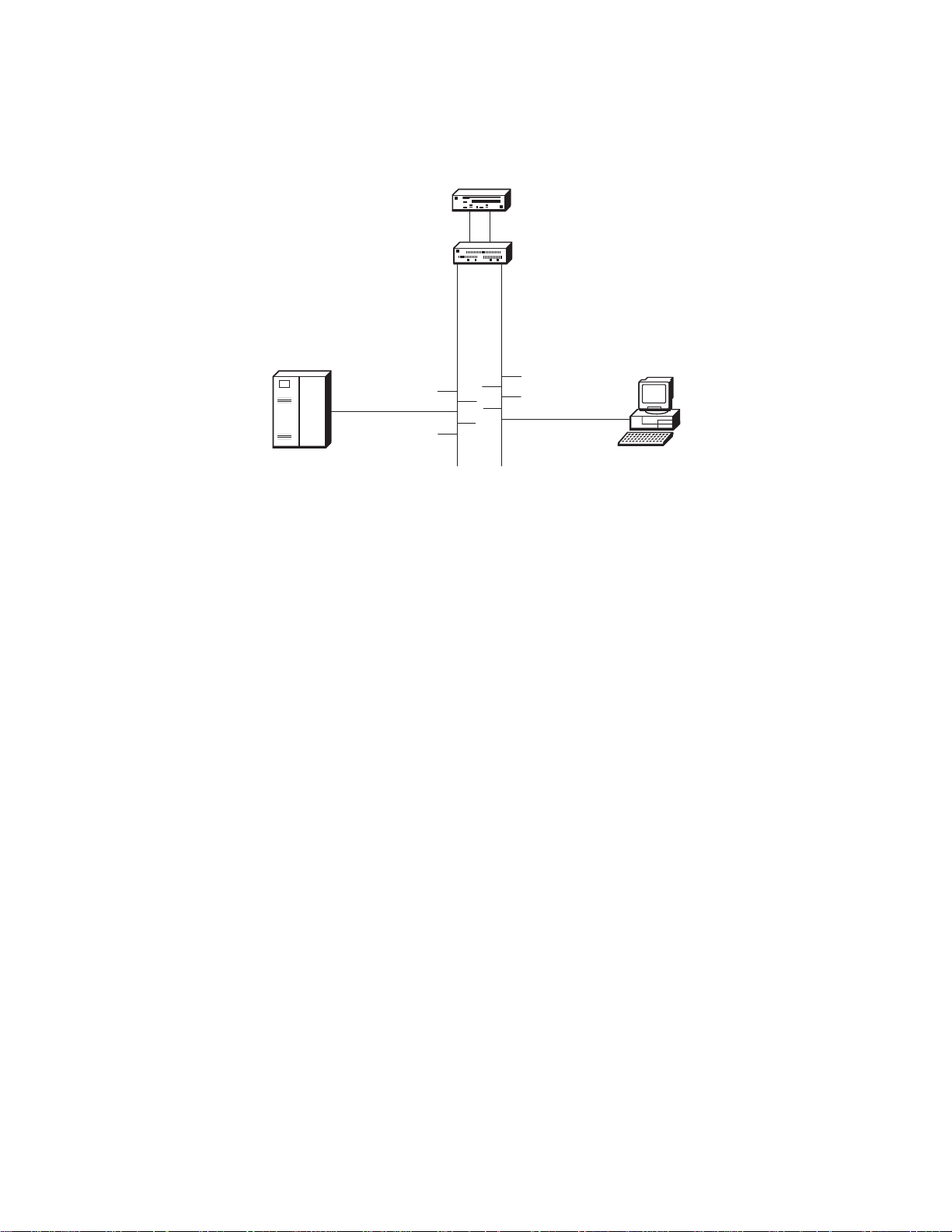
Self Learning IP
Self Learning IP is a configurable function of the switch that learns where IP
addresses are in the network so that packets normally sent from one host to
another through a router can bypass the router and be sent directly to the
destination host address. Self Learning IP is most effective when the switch is used
to “front” the router (the switch is positioned logically between the router and the
networks to which it belongs). Because of this strategic vantage point in the network
(Figure 1 on page 3), the switch has visibility to all packets flowing to and from the
2 8275-416 User’s Guide
Page 19
router, as well as between any two switch ports. The switch monitors the traffic to
determine if a Layer 2 shortcut can be used instead of subjecting the packet to
Layer 3 router processing which can be relatively lengthy.
Router
Switch
1.1.1.x
Subnet
Server
Host A
1.1.1.10
* Host = clients or servers
Figure 1. Self-Learning IP in the network
2.2.2.x
Subnet
Host B
2.2.2.20
The Self Learning IP function essentially:
v Learns the network structure, classifying attached devices as routers or hosts.
v Maintains knowledge of network structure, aging out unused devices over time.
v Expedites packet flow through the network by circumventing the router whenever
possible.
Device learning and classification is accomplished by watching ARP replies that
flow naturally through the switch with the addition of active probing to determining
whether a device is a router or a host. When an IP packet enters the switch, the
Self Learning IP function compares the destination MAC address against the list of
known routers, then checks if the destination IP address is a known host. If both
tests pass, the packet is automatically re-addressed to the destination IP host
device and is sent out the appropriate switch port.
A Router Table and Host Table are used to manage information learned about
router and host devices, respectively. To keep this network information current, the
Router Table entries are refreshed every 5 minutes while Host Table entries are
checked every 3 minutes. Devices which are no longer active are dropped from
their table; devices may be relearned at a later time as conditions change.
To use the Self Learning IP function, the switch must be configured with the
following:
v IP information (see Network Connectivity Configuration Menu in Chapter 4).
Note: For the Self Learning IP function to work, the IP information must include
a default gateway for the network.
v Enable the Self Learning IP function (see the Switch Configuration Menu in
Chapter 4).
Chapter 1. Introduction 3
Page 20

Once Self Learning IP is enabled, the following information is available:
v Self Learning IP statistics for the switch (see Switch Detailed Statistics Menu in
Chapter 4).
v IP and MAC addresses of routers learned (see Self Learning IP Router Table
Menu in Chapter 4).
v Host IP statistics (see Self Learning IP Host Address Menu in Chapter 4).
Note that the Packets Switched count included in the Switch Detailed Statistics
Menu may not reflect the absolute latest value. The information used for updating
this count is obtained as individual Host Table entries are refreshed, so while this
value can change over time, it does not necessarily update at the same frequency
as other statistics on the menu.
While intended as an autonomous feature, Self Learning IP is affected by certain
changes in switch configuration. If Self Learning IP is enabled and the switch IP
address is reset, the Self Learning IP function is automatically disabled. The Self
Learning IP Router and Host Tables are cleared whenever there is a link
aggregation configuration change (see Link aggregation (trunking) in this chapter),
forcing router and host devices to be relearned.
Link aggregation (trunking)
Link aggregation, also called
together logically to appear as one super-link. The super-link or Link Aggregation
Group (LAG) has access to the combined bandwidth of all links.
trunking
allows 802.3 MAC interfaces to be grouped
The Sun Trunking
100BASE-FX ports. All members of the trunk must support Sun Trunking
information about configuring trunks, see “Trunk management menu” on page 58.
Up to 8 trunks can be configured.
Advantages of trunking are:
v Fault tolerance: Failure of one or more of the links in the LAG are handled
gracefully. If a link of the LAG fails, the flows mapped to that link are dynamically
reassigned to the remaining links of the LAG.
v Redundancy: Link aggregation also provides automatic, point-to-point redundancy
between two devices (switch-to-switch).
Fast spanning tree mode
The IEEE 802.1D spanning tree protocol (STP) is designed to prevent loops in
Ethernet networks. To achieve this objective the STP does not allow switches to
forward data frames on a link immediately after the link is activated. The STP first
listens for spanning tree BPDUs from other switches, then determines whether to
put the link into forwarding state. When a default IEEE spanning tree timer value of
15 seconds is used for the forward delay timer, a link can start forwarding traffic 30
seconds after it becomes active on the network.
In networks with shared media hubs, there is a trend to attach network stations (or
hosts) directly to multi-port bridges (otherwise known as switches). Unfortunately,
the 802.1D spanning tree protocol has not been changed to accommodate this
trend. So, when a network station is ready to send data, the switch does not allow
the network station to communicate on the network until STP puts the port in
forwarding state. The 30 second delay forces the network station users to wait
™
1.0 specification is supported for the 10/100BASE-TX and
™
1.0. For
4 8275-416 User’s Guide
Page 21

longer before accessing the network. Even worse, some higher level protocols
running on the network station may time out, generate error messages or not work
at all.
The 802.1D standard specifies that when a link comes up on the network, the
spanning tree state is set to “Listening”. After the forward delay timer expires, the
spanning tree state is set to “Learning”, and after another forward delay timer
interval the state is set to “Forwarding”. The forward delay timer is set for the entire
network by the root bridge. The default value for this timer is 15 seconds.
With the Fast Spanning Tree function, the transition from “Listening” to “Learning”
and the transition from “Learning” to “Forwarding” takes approximately 6 to 8
seconds. The forward delay timer behavior reverts to the 802.1D standard (15
seconds) after a port goes into forwarding state or blocking state.
Fast Spanning Tree mode is configurable by port. The default is the standard
802.1D protocol. When a port is configured in Fast Spanning Tree mode, it takes
approximately 6 to 8 seconds before traffic can be forwarded on the link. Spanning
tree can also be disabled on the port. For details about configuring ports for Fast
Spanning Tree mode, see the Port Configuration Menu in Chapter 4.
Management and user interfaces
Note: The switch is manageable using the Ethernet network only through the ports
which are members of the Default VLAN (VLAN 1).
You have a choice of these easy-to-use management methods:
v A VT100 terminal interface allows you to fully manage the switch using a
standard terminal or terminal emulator connected over the network using Telnet
or connected to the switch’s serial port (EIA 232).
“Chapter 2. Accessing the switch” on page 19 describes how to access the switch
using this interface and “Chapter 4. Using the Terminal Interface” on page 31
instructs you about using this interface.
v A Web-based interface enables you to manage the switch through standard Web
browsers. There must be a physical path between the Web browser and the
switch over the Ethernet network to use this method of connectivity.
“Chapter 2. Accessing the switch” on page 19 describes how to access the switch
using this interface and “Chapter 5. Using the Web Interface” on page 81
instructs you about using this interface.
v The switch has a Simple Network Management Protocol (SNMP) agent that the
network administrator can access with a standard network manager. The
following MIBs (Management Information Base) are supported:
– MIB II (RFC 1213)
– 8275-416 Enterprise MIB
– RMON MIB (RFC 1757)
– Bridge MIB (RFC 1493)
– IEEE 802.3 Ethernet (RFC 1643)
v The switch interoperates with the following SNMP Managers:
– Any standard MIB browser (SNMPv1)
– IBM Nways
– IBM Nways Manager for HP-UX (V2.0 or later)
– IBM Nways Manager for AIX
®
Manager for Windows NT®(V2.0 or later)
®
(V2.0 or later)
Chapter 1. Introduction 5
Page 22

Security
User access security can be implemented using the following functions of the
8275-416:
v User Accounts: The switch supports up to six accounts (one user with read/write
status and five with read-only status) for terminal interface and Web access.
Access to the switch configuration panels is password protected. Only one user
name with read/write status is allowed to be configured, which prevents potential
conflicts in configuration changes. The default Read/Write user name is:
and the default password consists of blanks (no password). If you lose the
password, contact your IBM service representative.
v SNMP read/write protection based on community name.
Reliability and serviceability
The switch:
v Provides a comprehensive power-on self-test (POST) that ensures that all of its
components are functioning correctly.
v Controls a seven-segment LED that allows you to follow the boot sequence.
v Allows you to download software upgrades using any of the management
methods.
v Allows you to implement parallel paths for network traffic through the use of
spanning tree protocol (STP), which provides a level of fault tolerance and
ensures that:
– Redundant paths are disabled when the main paths are operational
– Redundant paths are enabled if the main paths fail
v Allows you to configure a port to “see” traffic going into and out of another port
on the switch (port monitoring).
v Provides statistics for all ports.
admin
,
Performance
High performance, Layer 2 switching for the switch consists of:
v Switching for up to 32 ports
v Supporting up to 12 000 end stations
v Processing 64-byte packets at the following rates:
– 14 880 packets per second to 10-Mbps ports.
– 148 800 packets per second to 100-Mbps ports
v Detecting broadcast storms and preventing them from impacting the network
(Broadcast Storm Recovery).
Year 2000 (Y2K) Compliance
The 8275-416 is Y2K compliant.
When used in accordance with its associated documentation, it is capable of
correctly processing and/or receiving date data within and between the 20th and
21st centuries providing all other products (for example, hardware, software, and
firmware) used with the switch properly exchange accurate date data.
For additional information about Year 2000 related topics, visit:
http://www.ibm.com/year2000
6 8275-416 User’s Guide
Page 23

Hardware
Cabling requirements
Ethernet cables are
them through your IBM representative.
Table 1 shows cable type and length requirements. Cable requirements depend on
the speed of the network. Cables and connecting hardware must meet the
standards specified in the ANSI/TIA/EIA 856-A or CSA T529 standards.
Table 1. Ethernet cable requirements
Ethernet Type Cable Requirements Max. Cable Length
10BASE-T Category 3, 4 or 5 100-ohm STP/UTP
100BASE-TX Category 5, 100-ohm STP or UTP
100BASE-FX 62.5-micron multimode fiber (MMF)
1000BASE-SX 50/125-micron or 62.5-micron
10/100BASE-TX
not
provided and must be separately purchased. You can order
100 m (328 ft)
cable
100 m (328 ft)
cable and connecting hardware
2 km (6561 ft) at full-duplex; 412
cabling
multimode fiber (MMF) cabling
m (1352 ft) at half-duplex
550 m (1804 ft) at full-duplex.
10BASE-T connections are MDX ports and operate correctly with standard
Category 3, 4, or 5 100-ohm UTP or STP cable and connecting hardware,
as specified in the ANSI/TIA/EIA 856-A or CSA T529 standards when
connected to MDI ports. When connecting to other MDX ports, such as
ports of other 8275-416 switches, you must use crossover cables.
Do not use telephone extension cables in 10/100BASE-TX networks. The
wire pairs in those cables are not twisted and the cables do not meet other
requirements for use in a 10BASE-T network.
For connections to 10/100BASE-TX networks, you can use only Category 5
STP or UTP cables.
100BASE-FX
For connection to 100BASE-FX networks, you can use only 62.5/125 MMF
cabling with MTRJ connectors.
1000BASE-SX
For connection to 1000BASE-SX networks, you can use 62.5/125 µm or
50/125 µm multi-mode fiber (MMF) cabling with SC fiber optic connectors.
Chapter 1. Introduction 7
Page 24
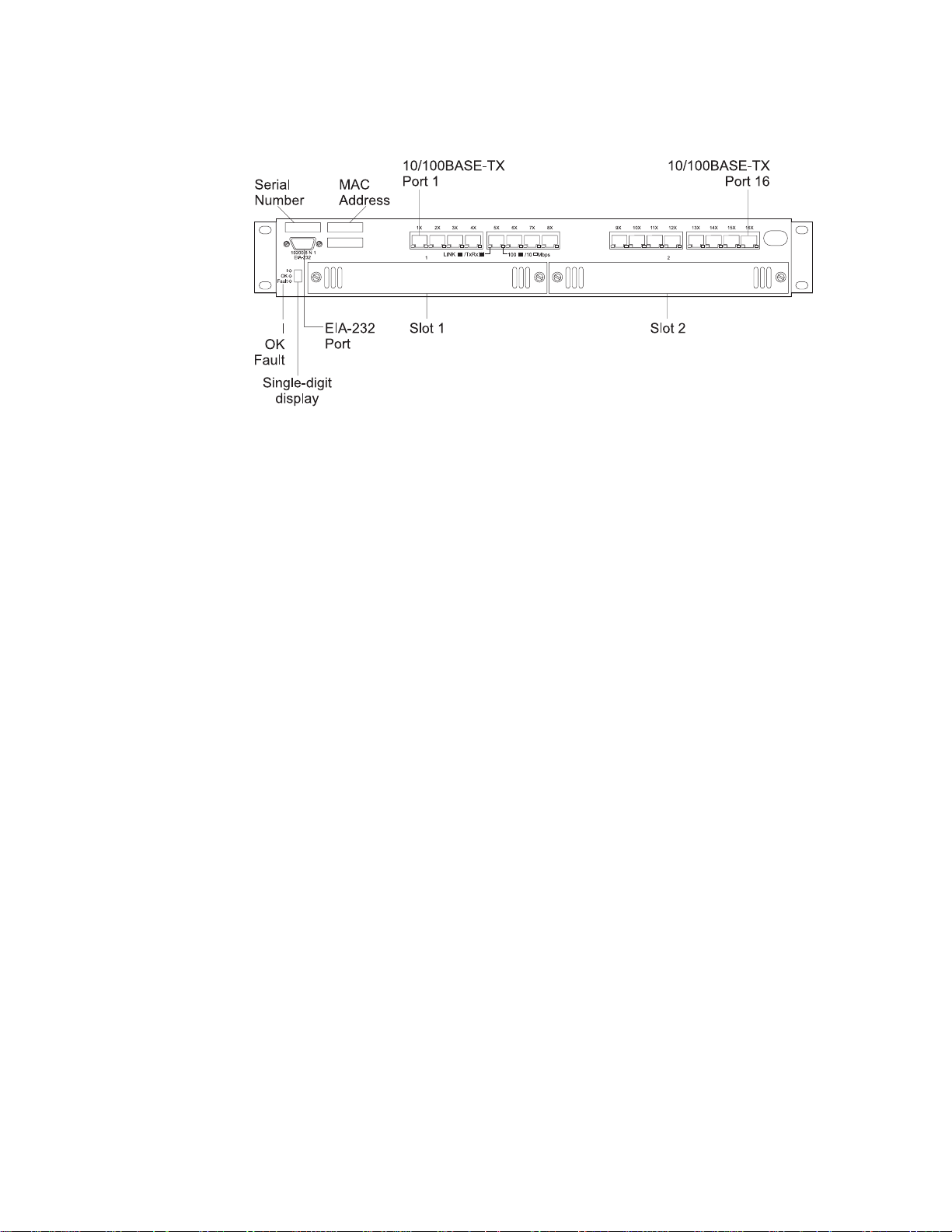
Front panel
Figure 2. Front panel of the switch.
Switch LEDs
Switch LEDs are located at the lower left corner of the front panel (left of
the single-digit display) and are identified with a vertical bar (I), OK, and
Fault. The LED identified with the vertical bar and the OK LED are Green;
the Fault LED is amber. The states of the LEDs are
They are explained later in this chapter.
on,off
,or
blinking
.
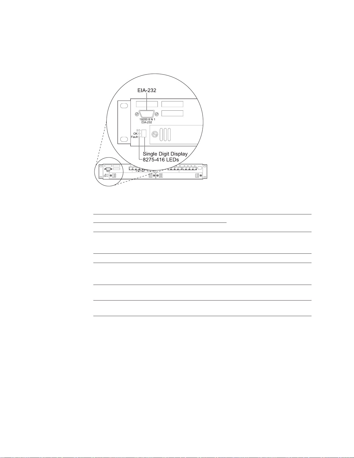
Single-Digit Display
The single-digit display is located at the lower left corner of the front panel
as shown in Figure 3 on page 10. During diagnostics, the character
displayed indicates the diagnostic test being executed. Once the switch is
operational, the character displayed is its unit ID (Table 3 on page 11).
Serial Port (EIA 232)
The serial port is a standard DB-9 male connector that provides an EIA 232
serial interface (sometimes referred to as the out-of-band management
port). Use a null-modem serial cable when connecting to a workstation
(“Appendix C. Cable Pinout Diagrams” on page 109). Use a VT100 terminal
emulator program to configure your terminal’s attached COM port as
follows:
v 19200 baud
v 8 data bits
v 1 stop bit
v No parity
v Hardware flow control OFF
See “Chapter 2. Accessing the switch” on page 19 for more information
about connectivity.
Ethernet 10/100BASE-TX Ports
The switch has 16 Ethernet 10/100BASE-TX ports. Each port has two LEDs
located at the lower right and left of the connector. Status indications of the
Port LEDs are explained later in this chapter.
8 8275-416 User’s Guide
Feature Module Slots 1 and 2
These feature modules are available to expand port connections for your
switch:
v 8-Port 10/100BASE-TX Ethernet Feature Module, P/N 30L6661
v 8-Port 100BASE-FX Ethernet Feature Module, P/N 30L6662
Page 25

v 4-Port 100BASE-FX Ethernet Feature Module, P/N 31L4054
v 2-Port 1000BASE-SX Ethernet Feature Module, P/N 30L6663
Chapter 1. Introduction 9
Page 26
Switch LED status
Switch LEDs are shown in Figure 3 and LED status is explained in the table that
follows:
Figure 3. LEDs for the switch.
Table 2. LED status for the switch.
I (Green) OK (Green) Fault (Yellow)
Off Off Off No power is present, or there is a
On On Off The switch is operational.
On Blinking Off Configuration file or Operational
On Off On There is a hardware fault. The
On Off Blinking Diagnostics are in process. The
LEDs Explanation
power supply failure. The switch is
not
operational.
Code file transfer is in process.
not
power-off or reset the switch.
switch is
switch is
not
operational.
not
yet operational.
Do
10 8275-416 User’s Guide
Note: Any other state of the LEDs indicates an LED failure.
Page 27

Single-digit display
The single-digit display (shown in Figure 3 on page 10) displays characters while
diagnostics are running after power is applied to the switch. At the successful
completion of diagnostics, the unit number appears in the display (for example, “1”
indicates Unit Number 1). Table 3 gives the meaning of other digits that can be
displayed and the corrective actions required.
Table 3. Problem indications on the single-digit display when the Fault LED is ON.
Character Problem Corrective Action
d Board RAM problem Replace the switch.
3 Detected an unsupported feature
4 PIF fault on the feature module or
5 or 6 Non-volatile memory problem. Replace the switch.
7 Switch memory problem. Replace the switch.
8 Base board loopback problem. Replace the switch.
9 or a Feature module loopback
module.
base board.
problem.
Remove the feature module and update
the operational code, or the feature
module is not fully seated in its
connector.
If feature module Fault LED is On,
remove the feature module. If no feature
module Fault LED is On, replace the
switch.
v 9 = Feature module in Slot 1 has the
fault; remove this feature module.
v a = Feature module in Slot 2 has the
fault; remove this feature module.
Chapter 1. Introduction 11
Page 28
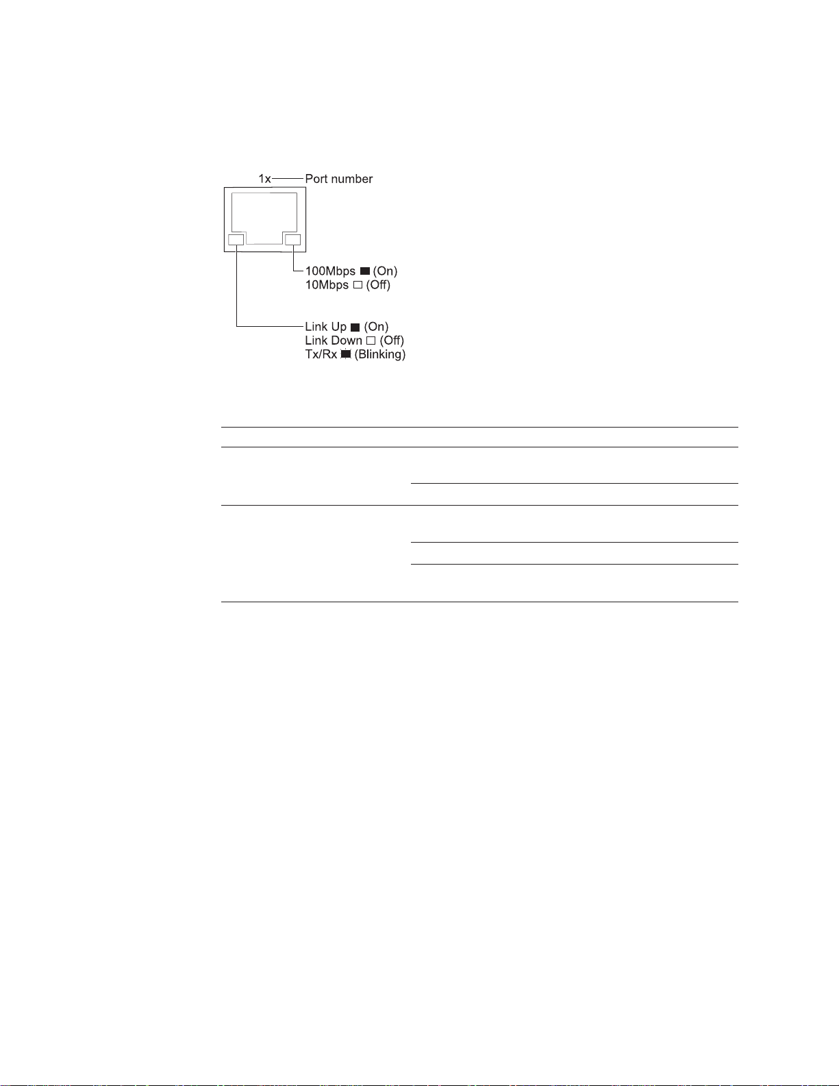
Base ports LEDs
The switch has 16 base 10/100BASE-TX ports. LED status for these 16 base ports
are shown in Figure 4 and they are explained in Table 4.
Figure 4. LEDs for the base 10/100BASE-TX ports on the switch
Table 4. Status of LEDs for 16 base 10/100BASE-TX ports
LED Color State Explanation
Right Ethernet
Port LED
Left Ethernet Port
LED
Green ON Indicates a 100-Mbps port.
OFF Indicates a 10-Mbps port.
Green ON The link is up.
OFF The link is down.
Blinking Transmitting (Tx) and Receiving (Rx)
traffic.
12 8275-416 User’s Guide
Page 29

Feature module LEDs
Each feature module has an OK and a Fault LED located at the left side of the
faceplate. The OK LED is green and the Fault LED is yellow. LED locations are
shown in Figure 5, Figure 6 on page 14, Figure 7 on page 15, and Figure 8 on
page 16; LED status of the feature modules are explained in Table 5, Table 6 on
page 14, Table 7 on page 15, and Table 8 on page 16.
Status LEDs for the 8-port 10/100BASE-TX Ethernet feature
module
8-Port 10/100BASE-TX Feature Module
15263748
OK
Fault
Feature
Module
LED
Port
LEDs
Figure 5. LEDs for the 8-port 10/100BASE-TX feature module.
Table 5. Status of LEDs for 8-port 10/100BASE-TX feature module
LED Color State Explanation
OK Green ON There is power to feature module.
OFF There is no power to feature module,
no power to the switch, or the module
has failed.
Fault Yellow ON There is a module fault.
OFF There is no module fault.
Right Ethernet
Port LED
Left Ethernet
Port LED
Green ON Indicates a 100-Mbps port.
OFF Indicates a 10-Mbps port.
Green ON The link is up.
OFF The link is down.
Blinking Transmitting (Tx) and Receiving (Rx)
traffic.
Chapter 1. Introduction 13
Page 30

Status LEDs for the 8-port 100BASE-FX Ethernet feature module
8-Port 100BASE-FX Feature Module
15263748
OK
Fault
Feature
Module
Port
LEDs
LED
Figure 6. LEDs for the 8-port 100BASE-FX feature module.
Table 6. Status of LEDs for 8-port 100BASE-FX feature module
LED Color State Explanation
OK Green ON There is power to the feature module.
OFF There is no power to the feature
module, no power to the switch, or the
module has failed.
Fault Yellow ON There is a module fault.
OFF There is no module fault.
Port LED Green ON Link is up.
OFF Link is down.
Blinking Transmitting (Tx) and receiving (Rx)
traffic.
14 8275-416 User’s Guide
Page 31

Status LEDs for the 4-port 100BASE-FX Ethernet feature module
4-Port 100BASE-FX Feature Module
1
OK
Fault
234
Link /TxRx
Feature
Module
Port
LEDs
LED
Figure 7. LEDs for the 4-port 100BASE-FX feature module.
Table 7. Status of LEDs for 4-port 100BASE-FX feature module
LED Color State Explanation
OK Green ON There is power to the feature module.
OFF There is no power to the feature module,
no power to the switch,or the module
has failed.
Fault Yellow ON There is a module fault.
OFF There is no module fault.
Port LED Green ON Link is up.
OFF Link is down.
Blinking Transmitting (Tx) and receiving (Rx)
traffic.
Chapter 1. Introduction 15
Page 32

Status LEDs for the 2-port 1000BASE-SX Ethernet feature
module
FRU 35L2357 1000SX
P/N 30L6663
OK
Fault
1 Link Tx/Rx 2
Figure 8. LEDs for the 2-port 1000BASE-SX feature module.
Table 8. Status of LEDs for 2-port 1000BASE-SX feature module
LED Color State Explanation
OK Green ON There is power to the feature module.
OFF There is no power to the feature module,
no power to the switch,or the module
has failed.
Fault Yellow ON There is a module fault.
OFF There is no module fault.
Port LED Green ON Link is up.
OFF Link is down.
Blinking Transmitting (Tx) and receiving (Rx)
traffic.
16 8275-416 User’s Guide
Page 33

Physical characteristics
Table 9 summarizes the physical characteristics for the switch:
Table 9. Summary of physical characteristics for the switch
Characteristic Specification
Physical Dimensions
Weight (estimate) 6.0 kg (13 lb)
Minimum Service Clearance
Height 63.0 mm (2.48 in.) 1.5 EIA rack units
Width 440.0 mm (17.16 in.)
Depth 355.6 mm (14 in.)
Front 15.3 mm (6 in.) for cooling, cables, and to view
LEDs
Sides 50 mm (2 in.) for cooling
Rear 15.3 mm (6 in.) for cooling and power cord
Environment
Operating Temperature
10° - 40° C (50° - 104° F)
Operating Humidity
8% - 80%
Storage Temperature
1° - 60° C (33.8° - 140° F)
Storage Humidity
8% - 80%
Shipment Temperature
-40°C - 60°C (-40°F - 140°F)
Shipment Humidity
5% - 100%
Chapter 1. Introduction 17
Page 34

18 8275-416 User’s Guide
Page 35

Chapter 2. Accessing the switch
This chapter explains the types of connections that you can use to physically
access the switch. Once the connection is established, you will configure the IP
information (either through the terminal interface or through DHCP or BootP), and
then choose which user interface you want to use to manage it. Therefore, all
interfaces support configuring the switch and obtaining information from it, thus
providing greater flexibility in how you manage your switch.
Types of Connectivity
There are two connection methods used to physically access the switch:
v Out-of-band connectivity, which provides access to the switch through the EIA
232 port.
v In-band connectivity, which provides access to the switch from a remote station
using the Ethernet network
Table 10 outlines the user interfaces that are available depending on your method
of connection.
Table 10. Connection methods and available user interfaces
Type of Connection Available User Interface
Out-of-band Terminal interface via the EIA 232 port
In-band
(terminal directly attached, or remotely
attached to modem)
v Terminal interface via Telnet
v SNMP-based management interface
v Web-based management interface
Out-of-band connection
Out-of-band connection lets you access your switch through the serial EIA 232 port.
It can be either through a locally attached PC running VT100 terminal emulation
software, or through a remotely attached PC running VT100 terminal emulation
software connected to a modem.
Locally attached terminal
To establish out-of-band connectivity using a locally attached terminal, make the
physical connections and set up using the following procedure:
1. Attach one end of a null-modem cable to the EIA 232 port of the switch as
shown in Figure 9 on page 20, and the other end to the COM port of your PC
(see “Appendix C. Cable Pinout Diagrams” on page 109).
© Copyright IBM Corp. 1999 19
Page 36

Figure 9. Out-of-band connectivity - locally attached terminal
2. Configure the VT100 terminal emulation application as follows:
v Baud rate: 19200
v Parity: None
v Data bits: 8
v Stop bits: 1
v Flow control: None
3. Log in to the terminal interface. The terminal interface requires you to log in with
a user name and password. The user name can have either Read/Write or
Read Only status. The default Read/Write user name is
password consists of blanks (no password). The default Read Only user name
guest
is
4. See “Appendix D. Interface Conventions for the Console” on page 113 for a
description of terminal interface key definitions. You may need to configure your
terminal emulation application to enable the use of these keys.
and the password consists of blanks (no password).
admin
and the
Remotely attached terminal
To establish out-of-band connectivity using a remotely attached terminal, make the
physical connections using the following procedure:
1. Unpack the modem and install it according to the manufacturer’s instructions.
2. Attach one end of the serial cable (not provided) to the EIA 232 port of the
switch and the other end to your modem as shown in Figure 10.
20 8275-416 User’s Guide
Figure 10. Out-of-band connectivity - remotely attached terminal
3. Set up the modem that is attached to the switch by following these steps:
a. Configure the modem to use the same settings as those on your switch.
v Baud rate: 19200
Page 37

v Parity: None
v Data bits: 8
v Stop bits: 1
v Flow control: None
b. Configuration command syntax varies from modem to modem. Make sure
that the modem has the following characteristics:
v Asynchronous mode
v Disable modem response
v Disable flow control (for example, AT \Q)
v Disable echo (for example, AT Q1)
v Autoanswer mode on second ring (for example, AT SO=2)
v Dumb mode - (No response in/out AT commands). This enables it to act
as a “pass thru” device (setting the modem to dumb mode [])
c. Set up the remote modem and terminal.
d. After configuring the modem, save the configuration.
e. Establish a modem link as described in the modem user documentation.
f. Login to the terminal interface. The terminal interface requires you to login
with a user name with read/write or read-only status and a password. The
default read/write user name is
(no password). The default read-only user name is
consists of blanks (no password).
g. See “Appendix D. Interface Conventions for the Console” on page 113 for a
description of terminal interface key definitions. You may need to configure
your terminal emulation application to enable use of these keys.
4. To use in-band connectivity, you must configure the switch with IP information
(IP address, subnet mask, and default gateway), and the port being used to
access the switch must be on the Default VLAN (VLAN 1). You can configure IP
information initially by using either of these methods:
v DHCP or BootP
v Terminal interface via the EIA 232 port.
admin
and the password consists of blanks
guest
and the password
To configure the IP information, see “Chapter 3. Configuring your switch” on
page 25 for details.
In-band connection – Telnet, Web, SNMP
Note: To use in-band connectivity, you must configure the switch with its IP
information (IP address, subnet mask, and default gateway), and have a
path available through the Default VLAN (VLAN 1). See “Chapter 3.
Configuring your switch” on page 25 for configuring BootP or DHCP and IP
information for your switch.
In-band connectivity allows access to the switch using the data network (as shown
in Figure 11 on page 22).
Chapter 2. Accessing the switch 21
Page 38

Figure 11. In-band connection
Terminal Interface – Telnet
Telnet console management can be performed through an Ethernet port (in-band
connection). You must configure an IP address before using Telnet console
management (Refer to “Chapter 3. Configuring your switch” on page 25 for initially
configuring IP information for your switch.
You can use any Telnet application that emulates a VT100 terminal to establish a
Telnet console management session. Up to five concurrent Telnet sessions are
supported. For security, the Telnet session can be automatically logged off after a
certain time of inactivity. You can configure the time of inactivity from 0 to 160
minutes; the default is 5 minutes.
The terminal interface is menu-driven and can be used to manage the switch
through the EIA 232 port or a Telnet session. For security, a login user ID and
password are required. Multiple user IDs and associated passwords can be created.
Two levels of access privileges are supported: read/write and read only.
See “Appendix D. Interface Conventions for the Console” on page 113 for a
description of the terminal keys. You may need to configure your terminal
application to enable use of these keys.
See “Chapter 4. Using the Terminal Interface” on page 31 for a description of the
terminal interface panels.
22 8275-416 User’s Guide
SNMP-Based Management Interface
The switch has an SNMP agent that supports SNMP Version 1 which allows it to be
managed by any SNMP-based application (for example, Nways Campus Manager
which supports the MIBs that the switch supports). See “Chapter 6. Using the
SNMP Interface” on page 85 for details about the MIBs supported by the switch.
Web-Based Management Interface
The switch has a Web server that supports HTTP 1.1 or later, and HTML 4.0 or
later. Your Web browser must support HTTP 1.1 or later, HTML 4.0 or later, and
JavaScript© 1.2.
You can use the Web interface to access and change switch parameters. Menus
similar to those available through the terminal interface are also displayed by the
Web browser. To access the switch from a Web browser, you must have configured
Page 39

the IP information for the switch. You will need a valid login user ID and password.
The accepted user IDs and passwords are the same as those configured for the
terminal interface.
The is no specific logout command to end a Web session. The Web session will be
automatically logged off after a period of inactivity. The inactivity timeout value that
is configured for the Telnet session is used by the Web interface.
See “Chapter 5. Using the Web Interface” on page 81 for starting and using the
Web interface.
Chapter 2. Accessing the switch 23
Page 40

24 8275-416 User’s Guide
Page 41

Chapter 3. Configuring your switch
After hardware installation, you must configure the IP information for your switch in
order to manage the switch using in-band connection.
First, you need to decide how you will access your switch. See “Chapter 2.
Accessing the switch” on page 19 for details about in-band and out-of-band
connection. It is assumed that when you come to this chapter you will already have
established physical connectivity.
Configuring IP information
IP information can be initially assigned through either:
v DHCP or BootP (the default), or
v Terminal interface through the EIA 232 serial port
Remote configuration using DHCP or BootP
You can configure your switch from remote locations using DHCP (Dynamic Host
Configuration Protocol) or BootP. BootP (documented in RFC 951 and RFC 1542) is
a bootstrap protocol used by a diskless workstation to learn its IP address, the
location of its boot file, and the boot server name. The switch supports “reserved” or
static DHCP, documented in RFC 1541. The DHCP or BootP server must be
available through the Default VLAN (VLAN 1).
To configure the IP information remotely using DHCP or BootP:
1. Select Management Menu from the Main Menu on the terminal interface.
2. Select Network Connectivity Configuration Menu from the Management
Menu, then specify
Current parameter. If you are not using BootP or DHCP, set the
Configuration Protocol Current
network traffic. You must reset the switch to activate the change.
BootP / Static DHCP
parameter with a value of
for the Network Configuration Protocol
Manual configuration using the terminal interface
To manually configure the IP information:
1. Log onto the terminal interface using the read/write user ID and password.
2. Select the Management Menu from the Main Menu.
3. Select Network Connectivity Configuration Menu from the Management
Menu, then specify IP address, Subnet Mask, and Default Gateway. Also,
None
ensure that
is specified for Network Configuration Protocol Current.
None
Network
to reduce
© Copyright IBM Corp. 1999 25
Page 42

Figure 12. Configuring BootP/static DHCP and network connection (IP information).
IP Address
Unique IP address of your switch. Each IP parameter is made up of four
decimal numbers. The numbers range from 0 to 255. The default for all IP
parameters consists of “0”s (that is, 0.0.0.0).
Subnet Mask
The subnet mask for the LAN.
Default Gateway
Identifies the address of the default router if the switch is a node outside
the IP range of the LAN.
Burned-in MAC Address
The default MAC address.
Locally Administered MAC Address
This is an additional parameter that you can configure. The following rules
apply:
v Bit 6 of byte 0 (called the U/L bit) indicates whether the address is
universally administered (B‘0’) or locally administered (B‘1’).
v Bit 7 of byte 0 (called the I/G bit) indicates whether the destination
address is an individual address (B‘0’) or a group address (B‘1’).
v A locally administered address must have bit 6 On (B‘1’) and bit 7 Off
(B‘0’).
MAC Address Type
Specifies if the burned-in MAC address or the locally-administered MAC
address should be used. The burned-in MAC address is the default MAC
address type.
Network Configuration Protocol Current
Specifies the network configuration protocol currently being used. Possible
values are:
v BootP / Static DHCP: the switch periodically sends requests to a BootP
or DHCP server until a response is received.
v None: the switch will be manually configured with IP information as
specified on the Network Connectivity Configuration Menu.
Network Configuration Protocol on Next Reset
When you select BootP/Static DHCP (the default), the switch periodically
26 8275-416 User’s Guide
Page 43

sends requests to a BootP or DHCP server until a response is received.
You must specify None, if you want to manually configure the switch with
the appropriate IP information. When this value is modified, you need to
issue a Save and then reset the switch in order for the new value to take
effect.
Web mode
Used to enable or disable access to the switch through the Web interface.
When enabled, you can login to the switch from the Web interface. When
disable is selected, you cannot login to the switch’s Web server. Specifying
Disable provides for more secure access to the switch. The default is
Enable.
Note: Disabling the Web interface will not disable Web sessions that are in
Configuration Changes
This section describes how to make configuration changes, apply them, and retain
the changes across a power cycle of the switch. It also provides you with specific
information about making configuration changes using the terminal interface, Web
interface, and SNMP interface.
You make configuration changes by entering data for one or more items.
Configuration changes made by one user are also seen by other users who request
the same data. Be aware that information displayed may be old data if you do not
request the latest information before making any changes.
progress; no new Web sessions will be started.
After you have make a configuration change and it is accepted:
v Selecting APPLY causes the change on the current panel to be applied but not
retained across a reset or power cycle.
v Selecting SAVE causes the change on the current panel to be applied and all
applied changes are retained across a reset or power cycle.
Making configuration changes using the terminal interface
This section provides information about making configuration changes, applying the
changes, and retaining the changes across a power cycle when using the terminal
interface.
Applying the configuration changes
On the terminal interface menus, field entries that can modified are enclosed in
either square brackets ([ ]) or angle brackets (< >).
Square brackets identify an item that you can change by typing in text. As soon as
you begin typing, the current value of the field is erased and is replaced by the new
text. You cannot perform insert or overwrite in the field. You can use the following
special keys while you are editing text fields:
v Arrow keys: These are ignored when you are editing a text field. On a field
where you have made no modifications, use arrow keys to move the cursor to
the appropriate field indicated by the direction of the arrow key.
v Backspace: Removes a character in front of the cursor.
v Delete: Gives the same result as the Back Space.
v Enter: The text is accepted and the cursor moves to the next field. On a text field
where you have made no modifications, Enter moves the cursor to the next field.
v Esc: Stops editing the field and restores the original data.
Chapter 3. Configuring your switch 27
Page 44

v Space Bar: Is an allowable key to enter text.
v Tab: Performs the same function as the Enter key.
v F4: Save. Causes the configuration data to be saved and also applied if not
already done.
Angle brackets identify an item that can be changed by selecting the desired option.
The following special keys are used while selecting a configuration option:
v Arrow keys: The text is accepted and the cursor moves to the appropriate field
indicated by the direction of the arrow key pressed. On a field where you have
made no modifications, arrow keys move the cursor to the appropriate field.
v Enter: The text is accepted and the cursor moves to the next field. On a field
where you have made no modifications, Enter moves the cursor to the next field.
v Esc: Stops modifying the field and restores the original data.
v Space Bar: Displays the next possible value for this field. Use it to cycle through
the available options to select the desired value.
v Tab: Performs the same function as the Enter key.
v F4: Save. Causes the configuration data to be saved and also applied if not
already done.
When processing data entered in a text field, all leading and trailing white-space
characters are ignored (such as, space, Tab, Esc).
Once a configuration change is made and is accepted (the cursor is no longer on
the field that was modified), the change is not put into effect until you select APPLY.
Saving the configuration changes
Note: To help remind you that a configuration change needs to be applied, APPLY
always appears on the Command Bar.
When you select APPLY, the following actions occur:
1. All configuration changes that you made are checked for correct syntax.
2. If you entered invalid configuration data (for example, data value that is out of
the supported range), an error message is displayed identifying the field that
contained the error. Errors are reported one field at a time. All data must be
valid before it can be applied.
3. When the data has been checked and you have corrected any errors,
UNSAVED DATA is displayed in the upper right corner of the panel.
If you make configuration changes and then exit a panel without applying the
changes, your changes may be lost. For example, the following results in losing any
changes made on the panel:
v You make configuration changes on the current panel and you select any of the
following commands:
– MAIN MENU
– PREV MENU
Note: Configuration changes are not automatically retained across a reset or a
power cycle. To retain changes, you must select the Save command as
described in the following section.
28 8275-416 User’s Guide
Page 45

Saving the configuration changes across a reset or power cycle
To save configuration changes across a reset or power cycle, perform one of the
following actions:
v Select F4 (Save).
v Select Save Applied Changes on the System Utilities Menu.
If you select SAVE without previously having selected APPLY for recently made
configuration changes, the changes are automatically applied.
If you request a switch reset without saving your configuration changes, you are
prompted to save them. Reply yes to save the changes or no if you do not want to
save them.
You are next prompted if you want to reset the switch. If you reply yes, the switch is
reset regardless of whether you saved the changes or not.
Making configuration changes using the Web interface
This section provides information on making configuration changes, getting the
changes put into effect, and retaining the changes across a power cycle when using
the Web Interface.
On the Web pages, field entries that can be modified are displayed in a box with a
white background. Depending on the field being modified, you can modify the text
by either:
v Typing in the appropriate text over existing text (overwriting). If the data typed in
is incorrect, the data entered is rejected and the original data is displayed.
v Selecting an option from one of the items displayed when the pull-down menu is
selected. All items in a pull-down menu are correct.
Until you select APPLY or SAVE, you can restore any modified values to their
original values by selecting the Undo.
Applying Configuration Changes
After you have modified the fields, select the APPLY or SAVE to process the
changes. Selecting APPLY makes the changes take effect but the changes are not
automatically retained across a reset or power cycle. Selecting SAVE makes the
changes take effect and also results in the changes being retained across a reset
or power cycle.
Before the Web Browser sends the request to the switch, the data for the fields
changed are verified. If any field is invalid, an error message is displayed identifying
the field that contains the error. Invalid data errors are reported one field at a time.
All configuration changes must be valid before any of the changes are sent.
If you make configuration changes and then change the page without applying or
saving the changes, the changes are not processed.
Saving configuration changes across a reset or power cycle
To save configuration changes to be retained across a reset or power cycle, select
SAVE. Configuration changes can be permanently saved by either of these actions:
v Selecting SAVE.
v Going to the System Utilities Menu and selecting Save All Applied Changes.
Chapter 3. Configuring your switch 29
Page 46

Making configuration changes using SNMP
This section provides information on making configuration changes, getting the
changes put into effect, and retaining the changes across a power cycle when using
the SNMP interface.
You make configuration changes using SNMP by issuing SNMP Set commands to
MIB objects that the switch supports as read/write.
Applying configuration changes
When the SNMP Set is received, the switch checks the data to ensure that it is
valid. If it is invalid, the SNMP error code BADVALUE is returned in the SNMP Set
Response. Otherwise, the configuration change is applied.
Saving configuration changes across a reset or power cycle
Configuration changes made using SNMP Set commands are not automatically
retained across a reset or power cycle. To get these changes retained across a
reset or power cycle, issue an SNMP Set to the swDevCtrlSaveConfiguration
object supported by the switch private MIB.
Managing the configuration file
Your switch’s configuration is written to a configuration file. Having this file available
at a remote location would allow you to restore a corrupted switch configuration.
System utilities allow you to upload files from the switch and download files to the
switch.
From the System Utilities panel, you can select to Upload File From Switch or
Download File to Switch to process a configuration file; just specify
the file type on either panel. The switch must have a path available through Default
VLAN (VLAN 1).
Config File
as
30 8275-416 User’s Guide
Page 47

Chapter 4. Using the Terminal Interface
This chapter describes the switch terminal interface. The terminal interface panels
are automatically refreshed every few seconds to provide you with current
information.
Note: The panels shown in this chapter are intended to be representative and
should not be assumed to be entirely accurate because they are subject to
change before final shipment of the product.
Login panel
The Login panel is the first panel displayed when initializing the terminal interface.
Figure 13 shows the Login panel; you need an approved user name and password
to login.
Figure 13. Login panel for terminal interface
User Name
Can be up to 8 alphanumeric characters in length. The value is not case
sensitive. The default is admin for a read/write user, and guest is the
default for a read only user.
Password
Can be up to 8 alphanumeric characters in length. The value is not case
sensitive. The default is no password.
The terminal interface provides a way to log out. From the Main Menu, select
LOGOUT or select System Utilities Menu, then select Logout. When you have
finished using the terminal interface, ensure you have saved all configuration
changes before logging out.
© Copyright IBM Corp. 1999 31
Page 48

The Main Menu
Following a successful login, the Main Menu appears (Figure 14). Information
following in this section is arranged in the order of topics on the Main Menu.
Figure 14. Main menu for terminal interface
System Information Menu
Management Menu
Device Configuration
Statistics Menu
User Account Management
System Utilities
System information
The switch manages information about its installed hardware and software. System
information contains read-only and read/write fields. The read-only fields are written
when the switch is manufactured. Through configuration you can change only the
read/write fields:
these fields must be saved to be effective. A reset is not necessary for the changes
to be effective.
Allows access to information that is maintained about the switch.
Contains selections associated with managing the switch.
Contains selections associated with configuring the switch.
Contains selections for access to statistical data that is gathered for the
switch.
Allows you to define users and passwords and their level of access.
Allows selection of the utilities available with the switch.
System Name,System Location
and
System Contact
. Changes to
32 8275-416 User’s Guide
To access system information, select System Information Menu on the Main
Menu. By selecting Inventory Information Menu and System Description Menu,
you can view information about your switch. Figure 15 on page 33 shows your
system information options.
Page 49

Figure 15. System information menu
Inventory information
Figure 16 shows the Read-Only inventory information available for your switch.
Figure 16. Inventory information menu
System description
Figure 17 on page 34 shows the system information for your switch.
Chapter 4. Using the Terminal Interface 33
Page 50

Figure 17. System description menu
System Name
The name assigned to the switch. Specify up to 31 alphanumeric
characters. The default is blank.
System Location
Indicates the physical location of the switch. Specify up to 31 alphanumeric
characters. The default is blank.
System Contact
Identifies the person responsible for your network (for example, you network
administrator) Specify up to 31 alphanumeric characters. The default is
blank.
34 8275-416 User’s Guide
Page 51

Management
Select Management Menu on the Main Menu (Figure 18) to use the management
functions of the switch.
Figure 18. Management menu
Configuring network connection for the switch
To configure the IP information, select Management Menu from the Main Menu,
then select Network Connectivity Configuration Menu from the Management
Menu. The Network Connectivity Configuration Menu appears as shown in
Figure 19.
Figure 19. Network connection configuration
Chapter 4. Using the Terminal Interface 35
Page 52

You must configure the following IP information to establish in-band connectivity to
the switch:
IP Address
Unique IP address for your switch. Each IP parameter is made up of four
decimal numbers. The numbers range from 0 to 255. The default for all IP
parameters consists of zeros (that is, 0.0.0.0).
Subnet Mask
The subnet mask for the LAN.
Default Gateway
Identifies the address of the default router if the switch is a node outside
the IP range of the LAN.
Burned-in MAC Address
The burned-in MAC address is the default MAC address used.
Locally Administered MAC Address
This is an additional parameter that you can configure. The following rules
apply:
v Bit 6 of byte 0 (called the U/L bit) indicates whether the address is
universally administered (B‘0’) or locally administered (B‘1’).
v Bit 7 of byte 0 (called the I/G bit) indicates whether the destination
address is an individual address (B‘0’) or a group address (B‘1’).
v A locally administered address must have bit 6 On (B‘1’) and bit 7 Off
(B‘0’).
MAC Address Type
Specifies if the burned-in MAC address or the locally-administered MAC
address should be used. The burned-in MAC address is the default MAC
address type.
Network Configuration Protocol Current
Specifies the network configuration protocol currently being used. Possible
values are:
v BootP / Static DHCP: the switch periodically sends requests to a BootP
or DHCP server until a response is received.
v None: the switch will be manually configured with IP information as
specified on the Network Connectivity Configuration Menu.
Network Configuration Protocol on next Reset
When you select BootP/Static DHCP (the default), the switch periodically
sends requests to a BootP or DHCP server until a response is received.
You must specify None, if you want to manually configure the switch with
the appropriate IP information. When this value is modified, you need to
issue a Save and then reset the switch in order for the new value to take
effect.
Web mode
Used to enable or disable access to the switch through the Web interface.
When enabled, you can login to the switch from the Web interface. When
disable is selected, you cannot login to the switch’s Web server. Specifying
Disable provides for more secure access to the switch. The default is
Enable.
Note: Disabling the Web interface will not disable Web sessions that are in
Configuring serial port
The switch allows you to access the switch through the serial EIA 232 port. This
type of connectivity is called out-of-band connection. See “Chapter 2. Accessing the
switch” on page 19 for descriptions of ways to access the switch.
36 8275-416 User’s Guide
progress; no new Web sessions will be started.
Page 53

On the Main Menu, select Management Menu. From the Management Menu,
select Serial Port Configuration Menu. Figure 20 shows the parameters to
configure the serial EIA 232 port.
Figure 20. Serial port configuration
You specify Login Timeout and Baud Rate:
Serial Port Login Timeout
Specifies the maximum connect time without console activity. The value is
in a range from 0 to 160 minutes. A value of 0 indicates that a console can
be connected indefinitely. The default value is 5 minutes.
Baud Rate
Specifies the communication rate of the terminal interface. Values can be
1200, 2400, 4800, 9600, 19200, 38400, 57600, or 115200. The default
value is 19200.
Configuring for DHCP or BootP
If you do not want to manually configure the switch with IP information, the switch
can obtain the IP information from a BootP or DHCP server. The switch must be
accessible through a port which is a member of the Default VLAN ID 1. When
BootP or DHCP is enabled, the switch periodically sends out requests until a
response is received from either a DHCP or BootP server. The IP information in the
BootP or DHCP response overlays any existing IP information in switch. The new IP
information is not retained across a reset until you select Save.
Note: If you configure a switch with an IP address, then DHCP frames will
effectively be ignored (that is, the configured IP address will have priority
over the address received via DHCP). However, BootP frames will have
priority over a configured IP address. A difference between BootP and DHCP
frames is that DHCP frames have 0xFFFFFFFFFFFF as the destination
MAC address, while BootP frames have the switch’s individual MAC address
as the destination address.
Configuring the DHCP
To configure the DHCP server for static DHCP, you must specify an IP address that
will be assigned to the switch. This IP address is mapped to the switch’s MAC
Chapter 4. Using the Terminal Interface 37
Page 54

address. The static DHCP does not obtain an IP address from a pool of addresses
on a DHCP server unless one is explicitly set up for a given MAC address. For
example, In Windows NT
®
, you must set up a reservation for the switch’s MAC
address. Assign an IP address from the pool of current addresses. Configure the
router, IP address, and subnet mask for the switch’s MAC address. The switch
supports no other DHCP options.
Configuring the BootP
For BootP, the BootP server must have the appropriate information configured for
the switch. A newly installed switch broadcast a BootP request over IP when it is
powered on or reset. The BootP server, using information from its BOOTPTAB file,
provides the switch with configuration information.
The following is an example of a BOOTPTAB file entry containing configuration
information for the switch:
8275_416_Switch_1:ht=ethernet:ha=0004ac6b0980:\
ip=10.1.7.7:gw=10.1.1.1:\
sm=255.255.255.0
8275_416_Switch_2:ht=ethernet:ha=0004ac6b09C0:\
ip=10.1.7.8:gw=10.1.1.1:\
sm=255.255.255.0
Where:
ht hardware type
ha host hardware address
ip host IP address
gw gateway address list
sm subnet mask
Configuration information obtained from the BootP server is not saved unless you
select SAVE. Next, configure the Network Configuration Protocol.
Configuring the switch for DHCP or BootP
If you are using DHCP or BootP, you must configure the appropriate information for
the switch. To do so, configure the Network Configuration Protocol as follows:
1. On the Main Menu, select Management Menu.
2. On the Management Menu, select Network Connectivity Configuration Menu,
then complete the network connection information shown in Figure 19 on
page 35.
Configuring the SNMP community
The switch has an SNMP agent that complies with SNMP Version 1 (SNMPv1). For
more about the SNMP specification, see the appropriate SNMP RFCs. The SNMP
agent sends traps through TCP/IP to an external SNMP manager based on your
SNMP configuration. SNMP configuration for the switch includes configuring the trap
receiver and SNMP community parameters, which are described in the following
text.
38 8275-416 User’s Guide
If you do not use the default community information, you must configure the SNMP
agent with a community name for the switch. A community name is a name
associated with the switch and with a set of SNMP managers allowed to manage it
with a specified privileged level. You can add, change or delete communities. The
switch does not have to be reset for changes to take effect. Up to six communities
are simultaneously supported.
Page 55

Community names in the SNMP community table must be unique. If you make
multiple entries using the same community name, the first entry is kept and
processed and all duplicate entries are ignored.
To configure your SNMP communities, select SNMP Community Configuration
Menu from the Management Menu. Figure 21 shows SNMP community information
you need to specify.
Figure 21. SNMP community configuration
SNMP Community Name
This name identifies each SNMP community; the name can be up to 16
characters, and it is case-sensitive. A
read only access. A
private
community is for users who have read/write
access. Two communities have default values. The default names are
Public and Private. You can replace these default community names with
unique identifiers for each community. The default values for the remaining
four community names are blank.
Client IP Address
This attribute is an IP address (or portion thereof) from which this device
will accept SNMP packets with the associated community. The requesting
entity’s IP address is logical-ANDed with the Client IP Mask and the result
must match the Client IP Address. The default value is 0.0.0.0.
Note: If the Client IP Mask is set to 0.0.0.0, a Client IP Address of 0.0.0.0
matches all IP addresses.
Client IP Mask
This attribute is a mask to be logical-ANDed with the requesting entity’s IP
address before comparison with the Client IP Address. If the result matches
with Client IP Address then the address is an authenticated IP address. For
example, if the Client IP Address is 9.47.128.0 and the corresponding Client
IP Mask is 255.255.255.0, a range of incoming IP addresses would match,
that is, the incoming IP addresses could be a value in the following range:
9.47.128.0 to 9.47.128.255.
public
community means users have
Chapter 4. Using the Terminal Interface 39
Page 56

To have a specific IP address be the only authenticated IP address, set the
Client IP Address to the required IP address and set the Client IP Mask to
255.255.255.255. The default for the Client IP Mask is 0.0.0.0.
Access Mode
This value can be read-only or read/write. A community with a read-only
access allows for switch information to be displayed. A community with a
read/write access allows for configuration changes to be made and for
information to be displayed.
A community name with read-only access is restricted from viewing SNMP
community and SNMP trap receiver information.
Status
This attribute has the following values: Enable, Disable and Delete on the
terminal and Web interface and Active, Inactive, and Delete on SNMP.
A community status of Enable/Active means that the community is active,
allowing SNMP managers associated with this community to manage the
switch according to its access right.
A community status of Disable/Inactive means that the community is not
active; no SNMP requests using this community will be accepted. In this
case the SNMP manager associated with this community cannot manage
the switch until the Status is changed back to Enable/Active.
A community status of Delete means that this name will be removed from
the table. The default Status values for the default private and public
community names are both Enable/Active. The default value is
Delete/Inactive for the 4 undefined community names.
Configuring the trap receiver
Trap messages are sent across a network to an SNMP Network Manager. These
messages alert the manager to events occurring within the switch or on the
network. Up to six simultaneous trap receivers are supported.
IP Addresses in the SNMP trap receiver table must be unique. If you make multiple
entries using the same IP address, the first entry is kept and processed and all
duplicate entries are ignored.
To configure trap receivers, select SNMP Trap Receiver Configuration Menu on
the Management Menu. Figure 22 on page 41 shows the parameters you need to
specify.
40 8275-416 User’s Guide
Page 57

Figure 22. SNMP trap receiver configuration
Trap receiver parameters are:
SNMP Community Name
IP Address
Status
Configuring traps
Configuring trap conditions
You can optionally configure which traps that the switch should generate. You do
this by selecting a status for the trap condition, that is, if it is either enabled or
disabled. If a trap condition is enabled and the condition is detected, the switch’s
SNMP agent sends the trap to all enabled trap receivers. Otherwise, no condition is
detected and no trap is sent. The default Status value for all Trap Conditions is
Enabled. The switch does not have to be reset to implement the changes. Cold
start traps are always generated; there are no associated trap conditions.
This is the SNMP community name of the remote network manager; the
name can be up to 16 characters, and is case-sensitive. The default value
for the 6 undefined community names is Delete.
Each IP address parameter is four decimal numbers. The numbers range
from 0 to 255. The default IP address is 0.0.0.0.
The status for trap receivers can be Enabled, Disabled, or Deleted. Trap
receivers with Enabled status are active and the SNMP agent sends traps
to them. Trap receivers with Disabled status are inactive and the SNMP
agent does not send traps to them. Trap receivers with a Deleted status are
removed from the table.
To configure trap conditions, select Trap Menu from the Management Menu. From
the Trap Menu, select Trap Flag Configuration Menu, then enable or disable trap
flags.
Figure 23 on page 42 shows the trap flags that you can set.
Chapter 4. Using the Terminal Interface 41
Page 58

Figure 23. Trap flags configuration
These are the trap conditions that can be enabled/disabled:
Authentication Flag
Enable/Disable authentication Flag.
Link Up/Down Flag
Enable/Disable Link Up/Link Down traps for the entire switch. When set to
Enable, the Link Up/Down traps will be sent only if the Link Trap flag setting
associated with the port (Port Configuration Menu) is set to Enable.
Multiple Users Flag
Enable/Disable Multiple User traps. When the value is set to Enable, a
Multiple User Trap is sent whenever someone logs in to the terminal
interface (EIA 232 or Telnet) and there is already an existing terminal
interface session.
Spanning Tree Flag
This flag enables the sending of new root traps and topology change
notification traps. See “Appendix E. Introduction to Virtual LANs (VLANs)”
on page 117 for more information.
Broadcast Storm Flag
This flag enables or disables the broadcast storm trap. You must also
enable Broadcast Storm Recovery Mode (see the Switch Configuration
Menu). The default is Disable. When this value is set to Enable and
Broadcast Storm Recovery mode is set to Enable, the Broadcast Storm
Start/End traps are sent when the switch enters and leaves Broadcast
Storm Recovery.
42 8275-416 User’s Guide
Trap log
The switch maintains a Trap Log; it contains a maximum of 256 entries that wrap.
Trap Log information is not retained across a switch reset.
Select Trap Menu from the Management Menu, then select Trap Log Menu from
the Trap Menu. Figure 24 on page 43 shows the entries in the trap log.
Page 59

Figure 24. Trap log
Each entry contains:
System Up Time
This entry shows how long the system has been up when the trap occurred.
Trap This entry is the name of the trap condition, which can be:
v Cold Start
v Authentication Failure
v Link Up
v Link Down
v Multiple Users
v New Spanning Tree Root
v Spanning Tree Topology Change
v Broadcast storm start/end
Checking trap log status
To check how many traps have been generated, select Trap Menu from the
Management Menu, then select Trap Log Status Menu from the Trap Menu.
You can choose to clear the trap log on this panel (Figure 25 on page 44).
Chapter 4. Using the Terminal Interface 43
Page 60

Figure 25. Trap log status
You can perform this operation on this panel:
Clear Trap Log
Configuring Telnet
You can manage the switch remotely using a Telnet connection. “Chapter 2.
Accessing the switch” on page 19 describes setting up a Telnet connection. To
configure for Telnet, select Management Menu from the Main Menu, then from the
Management Menu, select Telnet Configuration Menu (Figure 26).
Specify Yes or No.
No
causes the trap log to continue logging trap information after the last
entry.
Yes
causes the contents of the Trap Log to be erased.
44 8275-416 User’s Guide
Figure 26. Telnet configuration
Page 61

Ping
The following parameters are for configuring a Telnet session with the switch:
Telnet Login Timeout
A session is active as long as the session has not remained idle for the
value set. Specify a decimal value from 0 to 160 minutes. A value of 0
indicates that a Telnet session remains active indefinitely. The default is 5
minutes.
Note: Changing the timeout value for active sessions does not become
effective until the session is reaccessed. Any keystroke will also
activate the new timeout duration.
Maximum Number of Telnet Sessions
Specify a decimal value from 0 to 5. If the value is 0, no Telnet session can
be established. The default value is 5.
Allow New Telnet Sessions
Yes
Specify Yes or No.
until there are no more sessions available.
sessions are to be established. Any already established session remains
active until the session is ended or an abnormal network error ends it. The
default value is Yes.
The switch provides a ping utility that you can use to check connectivity between
devices in a network. To use ping, the switch must be configured correctly for
network (in-band) connection. The source and target devices must have the ping
utility enabled and running on top of TCP/IP. The switch can be pinged from any IP
workstation with which the switch is connected through the Default VLAN (VLAN 1)
(as long as there is a physical path between the switch and the workstation). The
terminal interface allows you to send one ping, three pings or a continuous ping
(one every second) to the target station.
means that new Telnet sessions can be established
No
means that no new Telnet
To use Ping, select Management Menu from the Main Menu. Then select Ping
Menu from the Management Menu (Figure 27).
Figure 27. Ping
You must supply this information:
Chapter 4. Using the Terminal Interface 45
Page 62

ARP cache
IP Address
The IP address of the target station. The value is 4 decimal bytes ranging
from 0 to 256. The default is 0.0.0.0.
Ping Count
You can select one of these values; the default value is single:
v Single–one ping is sent to target station.
v Multiple–three pings are sent to the target station.
v Continuous–a ping is sent every second.
Command
Send is the only command. To stop sending pings, press any key that
moves the cursor from the current field.
Select Management Menu from the Main Menu. Then select ARP Cache Menu
from the Management Menu to displays the ARP cache for the switch.
This is used to check connectivity between the switch and other devices. The ARP
cache identifies the MAC addresses of the IP stations communicating with the
switch. Figure 28 shows ARP Cache information.
46 8275-416 User’s Guide
Figure 28. ARP cache
Page 63

Device configuration
To configure the switch, select Device Configuration Menu on the Main Menu.
Figure 29 shows your options.
Figure 29. Device configuration
Configuring the switch
The switch allows you to set a time after which the address will timeout, and to
enable/disable broadcast storm recovery and 802.3x flow control. To set these
values, select Device Configuration Menu from the Main Menu and then select
Switch Configuration Menu (Figure 30).
Figure 30. Switch configuration
The value you specify is:
Chapter 4. Using the Terminal Interface 47
Page 64

Address Aging Timeout
Indicates the timeout period (in seconds) for aging out dynamically learned
forwarding information. The range is 10 to 600 (seconds). The default is
300 (seconds).
Broadcast Storm Recovery Mode
When you specify Enable for Broadcast Storm Recovery and the broadcast
traffic on any Ethernet port exceeds 20 percent of the link speed, the switch
blocks (discards) the broadcast traffic until the broadcast traffic returns to 10
percent or less.
When you specify Disable for Broadcast Recovery Mode, then the switch
will not block any broadcast traffic on any Ethernet port. The default is
Disable.
802.3x Flow Control Mode
Indicates if 802.3x flow control is enabled for the switch. The default is
Disable. This value applies to only full-duplex mode ports.
Self Learning IP Mode
Indicates that the self-learning IP mode is enabled or disabled. Disable is
the default.
Note: For the Self Learning IP function to work, the IP information must
include a default gateway for the network.
When you specify Enable, self-learning IP entries can be viewed on the
second panel (Page 2 of 2) of the Switch Detailed Statistics Menu (see
“Switch detailed statistics” on page 64).
Configuring ports
The switch is shipped from the factory with default port settings that allow it to
automatically determine the port type and speed.
See “Chapter 3. Configuring your switch” on page 25 for details about making and
saving configuration changes.
To configure the ports, select Device Configuration Menu from the Main Menu,
then select Port Configuration Menu from the Device Configuration Menu
(Figure 31 on page 49).
48 8275-416 User’s Guide
Page 65

Figure 31. Port configuration
You can select or change the following values:
Slot This is a read/write field. The 16 base ports are associated with slot 0. A
feature module in Slot 1 or Slot 2 can have 2, 4, or 8 ports associated with
each of them, depending on the feature module that is installed.
All
Port You can use the
option to change the value for all ports in this slot. You
can specify Enable or Disable for the Admin Mode and Link Trap fields.
Note that when All is specified and you specify Disable in the Admin Mode
field, you lose in-band connection to the switch.
Indicates the port number.
The feature slots are Slot 1 and Slot 2. Available feature modules have 2,
4, and 8 ports.
Type This is a read only field. It indicates whether a port currently belongs to a
trunk or is enabled for monitoring. Type values are:
v Trnk: indicates that this port belongs to a trunk.
v Mntr: indicates that this port is enabled for port monitoring.
STP Mode
This is a configurable parameter. It specifies the spanning tree protocol
mode for the port. STP mode values are:
v 802.1D (the default)
v Fast, indicates you want to use the fast spanning tree mode
v Off, indicates the STP mode is turned off for a particular port
STP St. (STP state)
This is a read-only field. It contains a single letter to indicate the current
spanning tree protocol state, which can be:
v D: disabled
v B: blocking
v l: listening
v L: learning
v F: forwarding
v X: indicates port is diagnostically disabled
Chapter 4. Using the Terminal Interface 49
Page 66

Admin Mode
This is a configurable value and indicates if the port is enabled or disabled.
The default for all ports is Enabled.
Physical Mode
This is a configurable value and indicates the speed and duplex setting for
the port. The value of Auto (autodetect) is valid only for 10/100BASE-TX
ports.
v Auto: automatically negotiates the speed and duplex setting
v 100 Half: 100BASE-T half-duplex
v 100 Full: 100BASE-T full duplex
v 10 Half: 10BASE-T half duplex
v 10 Full: 100BASE-T full duplex
v 100FX Half: 100BASE-FX half duplex
v 100FX Full: 100BASE-FX full duplex
v 1000SX Full: 1000BASE-SX full duplex
Physical Status
Indicates the port speed and duplex. This is a read-only field.
Link Status
Indicates if the port link is up or down. This is a read-only field.
Link Trap
This is a configurable value and can be Enabled or Disabled. It allows you
to enable or disable link status traps by port. This parameter is only valid
when Link Up/Down Flag is enabled on the Trap Flags Configuration Menu.
IfIndex
This is a read-only field. When using SNMP, the interface index (ifIndex) is
used to identify the specific interface being addressed. The ifIndex is
determined by MIB II.
Configuring port monitoring
You can select any of the Ethernet ports as a probe to monitor forwarded traffic (not
local traffic) with an external network analyzer. The selected probe port can monitor
(mirror) traffic from one port. The selected probe port also receives and transmits
network traffic (tagged frames) which allows a device connected to the probe port to
be managed over the network (in-band connectivity). However, the device must be
802.1Q aware to be remotely managed by the switch.
The monitoring port forwards frames with a VLAN membership which matches the
monitored port. The monitoring port transmits all frames as tagged. The monitoring
port does not participate in Spanning Tree Protocol (STP) and is always in a
forwarding state when the link is up. The monitoring port does not forward local
traffic, and it does not participate in GVRP.
Port Monitoring Operation
1. The monitoring port transmits all frames as tagged; therefore, a network
analyzer is remotely manageable only if it is 802.1Q-aware.
2. The monitoring port is unable to transmit frames outside of its VLAN
membership. Therefore, if the monitored port has ingress filtering disabled, any
frames received or forwarded on that port, and which are not affiliated with a
VLAN with which the monitored port is a member, will not be transmitted out of
the monitoring port.
3. The monitoring port always transmits frames with the NCFI bit set. Therefore,
frames not transmitted not on the monitored port due to untagging and a set
NCFI bit cannot be detected and filtered by the monitoring port. In this case, the
50 8275-416 User’s Guide
Page 67

monitoring port will transmit these frames, even though they are not transmitted
by the monitored port. The existence of such frames in a network is expected to
be a rare occurrence.
4. Frames not forwarded by the monitored port will not be monitored. These
include:
v Local frames
v 802.3x PAUSE frames
v Frames dropped due to ingress rules
v Frames dropped due to forwarding rules
From the Main Menu, select Device Configuration Menu and then, select Port
Monitoring Menu from the Device Configuration Menu (Figure 32).
Figure 32. Port monitoring
Specify values for the following parameters:
Port Monitoring
Used to
EnableorDisable
the port monitoring function. The default is
Disable.
Monitoring Port
This is the
slot.port
that the
monitored
that a Network Analyzer is attached to. The slot can be 0, 1 or 2. The
default is 0. The port range is 1 to 16 for Slot 0; 1 to 2, 1 to 4, or 1 to 8 for
Slots 1 and 2.
When Port Monitoring is Enabled, make sure that the monitoring port is
connected to a network analyzer and not to the network itself to avoid
potential problems.
Port to be Monitored
This is the port from which data is captured and sent to the monitoring port
(the port under analysis). The port range is 1 to 16 for Slot 0; 1 to 2, 1 to 4,
or 1 to 8 for Slots 1 and 2.
data is sent to. This is the
Chapter 4. Using the Terminal Interface 51
slot.port
Page 68

Configuring spanning tree protocol (STP)
Spanning tree switch configuration/status
The switch participates in Spanning Tree Protocol (STP). STP allows you to
configure redundant paths in the switch topology. The switch automatically blocks
redundant paths to prevent loops (that is, make it fault tolerant). If an active path is
broken and a backup path is available, the switch finds the redundant path and
enables it. Without STP, a path failure means loss of connectivity for the affected
part of the network.
The switch complies with the IEEE 802.1D standard. Refer to the IEEE 802.1D
document for STP specifications. The switch supports one Spanning Tree Protocol
(STP) for the entire switch.
To configure the Spanning Tree Protocol for the switch, select Device
Configuration Menu from the Main Menu, then select Spanning Tree Switch
Configuration/Status Menu or Spanning Tree Port Configuration/Status Menu
from the Device Configuration Menu (Figure 33).
52 8275-416 User’s Guide
Figure 33. Spanning tree switch configuration/status
The following section lists and describes the STP configuration functions and
related parameters.
Spanning Tree Algorithm
Indicates if the switch participates in Spanning Tree Protocol. A status of
Enable means that the switch participates in the STP. Disable means that
the switch does not participate in the STP. The default is Disable.
Bridge Priority
Decimal value that indicates the priority of the switch. The range is 0 to
65535. The lower the value, the higher the priority. The bridge with the
lowest priority value becomes the root (IEEE 802.1D). The default is 32768.
Maximum Age Time
When the switch is root, Maximum Age Time is the time in seconds during
which the configuration message used by the Spanning Tree Algorithm is
discarded. The range is 6 to 40 seconds. The default is 20 seconds.
Page 69

Hello Time
When the switch is root, Hello Time is the time in seconds that the switch
waits before sending the next configuration message. The range is 1 to 10
seconds. The default is 2 seconds.
Forward Delay Time
This value specifies the time spent in “Listening and Learning” mode before
forwarding packets. The range is 4 to 30 seconds. The default is 15
seconds.
Spanning tree port configuration/status
You can configure the Spanning Tree Protocol by ports. Select Device
Configuration Menu from the Main Menu. Then select Spanning Tree Port
Configuration/Status Menu from the Device Configuration Menu (Figure 34).
Figure 34. Spanning tree port configuration/status
The parameter values are:
Port Priority
Port Path Cost
VLAN management
“Appendix E. Introduction to Virtual LANs (VLANs)” on page 117 provides an
introduction to the terminology and concepts for VLANs. It is helpful to review this
material before you define values for the parameters associated with configuring
VLANs.
Decimal value which indicates the priority of port on the switch. The range
is 0 to 255. The default is 128.
This output is automatically calculated. The cost represents the shortest
distance from any switch to the root switch interval for the unit announcing
its presence on the network. The range is 1 to 65535. The port path cost
defaults to 0, which means that the path cost will be assigned dynamically
depending upon the detected speed of the port. A value of 100 is assigned
to 10 Mbps ports, and a value of 19 is assigned to 100 Mbps ports.
Chapter 4. Using the Terminal Interface 53
Page 70

From the Main Menu, select Device Configuration, and then select VLAN
Management Menu to begin configuring VLANs for your switch (Figure 35).
Figure 35. VLAN management menu
VLAN summary and configuration
From the VLAN Management Menu, select VLAN Summary and Configuration
Menu to begin configuring your VLANs (Figure 36). Note that there are four panels
on which you can define a total of 32 VLANs.
54 8275-416 User’s Guide
Figure 36. VLAN summary and configuration
The parameters for this panel are:
Unit ID
Selects the unit for which data is to be displayed or configured. In a
non-stacked environment the Unit ID is 1.
Page 71

VLAN Index
Sequential number of defined VLANs. You can configure 8 VLANs on each
of 4 pages for up to 32 VLANs.
VLAN ID
VLAN identifier. It can be any number from 2 to 4094 (ID 1 is reserved for
the default VLAN).
VLAN Name
An alphanumeric character string of up to 16 characters which identifies the
VLAN. The default name is blank. The name for VLAN ID 1 is always
Default
.
VLAN Type
The type can be the Default VLAN, a static VLAN (one that is permanently
configured and defined), or a dynamic VLAN (one that is created by GVRP
registration). A VALN maked as “Dynamic” can be made “Static” by toggling
Type
in the
field when the VLAN is being modified.
Adding or Modifying a VLAN
If you want to add a VLAN, move the cursor to the ADD VLAN command at the
bottom of the panel and press Enter. To modify an existing VLAN, move the cursor
to the line containing the VLAN and press Enter. You will be presented the VLAN
Configuration Menu (Figure 37).
Figure 37. VLAN Configuration Menu
The parameters for this panel are:
Port This value is not selectable. Indicates by slot ID and port number which port
is controlled by the fields on this line.
Slot ID
This value is not configurable. Indicates by slot ID and port number which
port is controlled by the fields on this line.
Participation
Determines the degree of participation of this port in this VLAN. The values
can be:
v Include: Indicates this port is always a member of this VLAN. This is
equivalent to registration fixed.
Chapter 4. Using the Terminal Interface 55
Page 72

v Exclude: Indicates this port is never a member of this VLAN. This is
equivalent to registration forbidden.
v Autodetect: Specifies the port is to be dynamically registered in this
VLAN by GVRP. The port will not participate in this VLAN unless a join
request is received on this port. This is equivalent to registration normal.
Tagging
Indicates the tagging behavior for this port in the VLAN. The values can be:
v Tagged: Specifies to transmit traffic for this VLAN as tagged frames.
v Untagged: Specifies to transmit traffic for this VLAN as untagged frames.
Type This value is not configurable. Indicates the port type. The values can be:
v Static: Indicates that the port is configured to be statically included in this
VLAN.
v Dynamic: Indicates that this port is to be dynamically registered in this
VLAN by GVRP.
v Monitor: Indicates that this is a monitoring port.
v blank (no text): Indicates that this port is excluded from being a member
of this VLAN.
If a monitoring port is configured, its VLAN membership always follows the
VLAN membership of the port being monitored. However, the VLAN
Configuration Menu always displays the monitoring port’s actual
configuration; this configuration will take effect when the port is no longer a
monitoring port.
Generic Attributes Registration Protocol (GARP) configuration
See Figure 38 for the GARP configuration parameters.
Figure 38. GARP configuration
56 8275-416 User’s Guide
GVRP Used to enable or disable GVRP (GARP VLAN Registration Protocol). The
default is Disabled.
GARP Timers
v Join Time: Specifies the interval between the transmission of GARP
PDUs registering (or reregistering) membership for a VLAN or multicast
Page 73

group. This value applies per port and per GARP. The value can be from
10 to 100 centiseconds (0.1 to 1.0 seconds). The default is 20
centiseconds (0.2 seconds).
v Leave Time: Specifies the period of time to wait after receiving an
unregister request for a VLAN or a multicast group before deleting the
VLAN entry. This can be considered a buffer time for another station to
assert registration for the same attribute in order to maintain
uninterrupted service. Values can be from 200 to 6000 centiseconds (2.0
to 60 seconds). The default is 60 centiseconds (0.6 seconds).
v Leave All Time: Controls how frequently Leave All PDUs are generated.
A Leave All PDU indicates that all registrations will be shortly
unregistered. Participants will need to rejoin in order to maintain
registration. This value applies per port and per GARP participation. The
value can be from 200 to 6000 centiseconds (2.0 to 60 seconds). The
default is 60 centiseconds (0.6 seconds).
802.1Q port configuration
See Figure 39 for parameters used to configure your 802.1Q ports.
Figure 39. 802.1Q port configuration
Port Indicates by a slot ID and port number which port is controlled by the fields
All
on this line.
specifies all ports on all slots.
Port VLAN ID
Indicates the VLAN ID that this port will assign to untagged frames or
priority-tagged frames received on this port. The value must be the ID of an
existing VLAN. The default is 1.
Acceptable Frame Types
Specifies the frames that will be passed through this port. The values can
VLAN onlyorAdmit All
be
. For VLAN only, untagged frames or priority
frames received on this port are discarded. For Admit All, untagged frames
or priority frames received on this port are accepted and assigned the value
of the Port VLAN ID for this port. With either option, VLAN tagged frames
are forwarded in accordance with the 802.1Q VLAN Specification.
Ingress Filtering
Indicates that ingress filtering is enabled or disabled. The default is
Chapter 4. Using the Terminal Interface 57
Page 74

Disabled. If disabled is specified, frames received with VLAN IDs which do
not match the VLAN membership of the receiving port are admitted and
forwarded to ports which are members of that VLAN.
GVRP Indicates that GVRP is enabled or disabled. The default is Disabled.
VLAN reset
This function allows you to reset VLAN configuration parameters to those default
parameters provided by the factory.
See Figure 40 for an example of the panel used to reset a VLAN.
Figure 40. VLAN reset
Trunk management menu
Link aggregation, also called trunking, allows multiple 802.3 MAC interfaces to be
grouped together logically to appear as one super-link. The super-link or Link
Aggregation Group (LAG) has access to the combined bandwidth of all links. Link
aggregation also provides automatic, point-to-point redundancy between two
devices (switch-to-switch). Each link in the trunk must be running at the same link
speed and in full-duplex mode (half-duplex mode is not supported).
Configuring a trunk
To configure (or create) a trunk, select Device Configuration on the Main Menu,
then select Trunk Management. The Trunk Status Menu (Figure 41 on page 59) is
displayed; it consist of two panels; Page 1 of 2 and Page 2 of 2. You can define up
to four trunks on each of these panels for a total of 8 trunks. To Configure a trunk,
complete the configuration information on the Trunk Status Menu, then move the
cursor to the ifIndex field, press Enter, and the Configure Trunk Menu (Figure 42 on
page 60) is displayed. Complete the configuration information on the Configure
Trunk Menu.
58 8275-416 User’s Guide
Page 75

Figure 41. Trunk status menu
ifIndex
Trunk interface number (ifIndex) values are fixed at 33 to 40. The interface
number is assigned by the switch and in a range above the numbers of the
ports (for example, ifIndex 33 to 36 is shown on panel 1of 2, and 37 to 40
is shown on panel 2 of 2). This field is not configurable.
Trunk Name
Defines the unique name for the trunk. You can use up to 15 alphanumeric
characters. There is no default trunk name.
Flush Timer
Specifies the time that all trunk ports will be disabled during trunk
transitions. This is done to ensure that frames are not misordered when
flows are re-assigned to new ports. “N/A” indicates the trunk is not
configured. The range of values is 100 to 4000 milliseconds (0.1 second to
4 seconds). The default is 1000 milliseconds (1 second).
Spanning Tree State
Specifies that spanning tree is either Enabled or Disabled for the trunk.
Trunk State
Specifies whether the trunk is Empty, LinkUp, or LinkDown. Empty indicates
the trunk is not configured.
Member Ports
Defines the port numbers associated with a specific trunk.
Chapter 4. Using the Terminal Interface 59
Page 76

Figure 42. Configure trunk menu
Name Defines the unique name for the trunk. You can use up to 15 alphanumeric
characters. There is no default trunk name.
Flush Timer
This value should match your network hold-time (that is, the time that the
switch holds a frame before forwarding or discarding it). The range is 100 to
4000 milliseconds (0.1 second to 4 seconds). The default is 1000
milliseconds (1 second).
Restore to Default
You can select yes or no. The default is No.
Admin Mode
Indicates whether the trunk group is Enabled or Disabled. The default is
Enable.
STP Mode
This is the value specified for STP Mode on the Port Configuration Menu. It
specifies the spanning tree protocol (STP) mode for the port; values are:
v 802.1D: the default
v Fast: indicates fast STP mode for this port
v Off: indicates STP is turned off for this port
Link Trap
Indicates whether link traps are Enabled or Disabled; Enable is the default.
60 8275-416 User’s Guide
Port This field is not configurable. For Slot 0, indicates the number of the port
(ports 1 to 8 are listed on the first panel (page 1 of 2) and ports 9 to 16 are
listed on the second panel (page 2 of 2)). For Slots 1 and 2, indicates the
number of the port (ports 1 and 2, 1 to 4, or 1 to 8 are listed on the first
panel) if the feature module is installed.
Include in Trunk
Indicates whether the port is included in trunk. You can specify No or Yes;
No is the default.
Page 77

Statistics
To access statistics, select Statistics Menu on the Main Menu. Traffic statistics are
kept by port. Details and summaries of packets broadcast, transmitted, and
switched, as well as error packets and discarded packets are the types of statistics
kept for your switch.
Figure 43 shows the types of statistics that you can select to view from the
Statistics Menu.
After making your selection, the panels containing statistics will refresh every few
seconds. All counters may not update every few seconds. Even though the refresh
rate is every few seconds, some counters will not change. For example, the
Self-Learning Statistics counters update on an as needed basis whenever a host
gets updated.
Note: A description for each statistic may be obtained by pressing Help on the
associated Web statistics panel.
Figure 43. Statistics Menu
Port summary statistics
To view a summary of port statistics, select Port Summary Statistics Menu from
the Statistics Menu. See Figure 44 on page 62 for a summary of port statistics that
are collected.
Chapter 4. Using the Terminal Interface 61
Page 78

Figure 44. Port summary statistics
Port detailed statistics
To view detailed port statistics, select Port Detailed Statistics Menu from the
Statistics Menu. Detailed port statistics can be viewed on four consecutive panels
(Figure 45, Figure 46 on page 63, Figure 47 on page 63, and Figure 48 on page 64).
To view the next panel, move the cursor to NEXT PAGE (at the bottom of each
panel) and press Enter.
62 8275-416 User’s Guide
Figure 45. Port detailed statistics (Page 1 of 4)
Page 79

Figure 46. Port detailed statistics (Page 2 of 4)
Figure 47. Port detailed statistics (Page 3 of 4)
Chapter 4. Using the Terminal Interface 63
Page 80

Figure 48. Port detailed statistics (Page 4 of 4)
Switch summary statistics
To view a summary of switch statistics, select Switch Summary Statistics Menu
from the Statistics Menu. See Figure 49 for a summary of the switch statistics that
are collected.
Figure 49. Switch summary statistics
Switch detailed statistics
To view detailed switch statistics, select Switch Detailed Statistics Menu (Page 1
of 2) from the Statistics Menu. See Figure 50 on page 65 for the detailed switch
statistics that are collected.
64 8275-416 User’s Guide
Page 81

To view Self Learning IP statistics, select Switch Detailed Statistics Menu (Page 2
of 2) from the Statistics Menu. See Figure 51 for an example of the statistics that
are collected for Self Learning IP.
Figure 50. Switch detailed statistics
Figure 51. Self Learning IP statistics
Packets switched
8-byte value containing the total number of packets directly switched by the
self-learning IP function since it was enabled. The count is all inclusive for
the switch, regardless of the routers or hosts involved. The value starts at 0
whenever the function is enabled and continues to increment until you reset
the function or the switch.
Known routers
Current number of known routers identified by the self-learning IP function
Chapter 4. Using the Terminal Interface 65
Page 82

since it was enabled. You cannot clear this counter. The value starts at 0
when the function is enabled and changes over time as routers are learned
and age-out.
Active Hosts
Current number of hosts (IP addresses) identified by the self-learning IP
function since it was last enabled. You cannot clear this counter. The value
starts at 0 when the function is enabled and changes over time as hosts
are learned and age out, reflecting the dynamic nature of host traffic as it
traverses the switch.
Forwarding database information
To view forwarding database information, select Forwarding Database Menu from
the Statistics Menu. See Figure 52 for the forwarding database information.
Figure 52. Forwarding database information
Self Learning IP router table menu
To view statistics about known routers whenever the Self Learning IP function is
enabled, select Statistics Menu from the Main Menu, then select Self Learning IP
Router Table Menu. See Figure 53 on page 67 for the router statistics.
66 8275-416 User’s Guide
Page 83

Figure 53. Self Learning IP router table menu
The description of the information collected is:
Number of known router entries
Current number of known routers identified by the Self Learning IP function
since it was enabled. This is the same value that is found on the Switch
Detailed Statistics Menu.
IP Address
The IP address of the router.
MAC Address
The MAC address of the router.
Notes:
1. The table is displayed in the order of increasing IP addresses.
2. The table can contain up to 32 entries, with up to 11 entries per page; up to 3
pages.
3. Only the number of pages that contain data are displayed.
Self Learning IP host address menu
To view information about IP host addresses that are collected when the Self
Learning IP function is enabled, select Statistics Menu from the Main Menu, then
select Self Learning IP Host Address Menu. See Figure 54 on page 68 for the
host IP statistics.
Chapter 4. Using the Terminal Interface 67
Page 84

Figure 54. Self Learning IP host address menu
Number of active host entries
Current number of hosts (IP addresses) identified by the Self Learning IP
function since it was last enabled. This is the same value that is displayed
on the Switch Detailed Statistics Menu.
IP Address of Host to Display
You specify the IP address of the host for which you want to view
information.
Host MAC Address
MAC address associated with the host’s IP address.
Host Unit.Slot.Port
Unit, slot, and port number for this host. If the port is part a trunk, then this
line is labeled “Trunk ifIndex” and the value is the ifIndex for this trunk.
Host Packets Switched
The number of IP packets destined for this host’s IP address that were
switched directly to this host address, bypassing the router, since the host
was last learned by the self-learning IP function.
Router (Gateway) IP Address
The IP address of the router to which this host communicates when
sending IP traffic to a different subnet (as viewed by the self-learning IP
function).
68 8275-416 User’s Guide
Router (Gateway) MAC Address
The MAC address of the router to which this host communicates when
sending IP traffic to a different subnet (as viewed by the self-leaning IP
function).
Notes:
1. When the panel is first displayed, the lines for the Host MAC Address, Router
MAC Address, Host Unit.Slot.Port, and Host Packets Switched are blank. After
the IP Address is entered and Apply is selected, these lines appear.
2. If the specified Host IP address is not found, the message “Information for <IP
address> is not available” where <IP address> is the value that was entered for
“IP Address of Host to Display”.
Page 85

3. The latest value for the Host Packets Switched count is shown whenever the
host information is displayed or manually refreshed. Changes in the count value
are also reflected in the Packets Switched value on the Switch Detailed
Statistics Menu.
Chapter 4. Using the Terminal Interface 69
Page 86

User account management
On the Main Menu, select User Account Management Menu to use the functions
for managing user accounts.
Defining user accounts
On the User Account Management Menu, select User Accounts Menu. Figure 55
shows the User Accounts Menu where you specify user names, passwords, and
access mode.
Figure 55. User account management
The switch allows you to add and delete users and set user passwords for the
switch. You are to provide the following information:
User Name
User name can be up to eight alphanumeric characters and is not case
sensitive. Up to six user names (accounts) can be defined; one with
read/write access mode and five with read only access mode.
Password
The password can be up to eight alphanumeric characters and is not case
sensitive. A blank password indicates no password. The default value is
blank.
Confirm Password
The confirm password can be up to eight alphanumeric characters and is
not case sensitive. You should use the same password as defined in the
Password field. A blank confirm password indicates no password. The
default value is blank.
Access Mode
This value is not configurable. User access mode can be:
Read/Write
Only one user can be defined with read/write access mode per
switch. This user can change the status of other users, add and
delete users, change passwords and change configurations, and
use system utilities.
Read Only
Up to five users can be defined with read only access mode per
70 8275-416 User’s Guide
Page 87

Status
Status applies to Read only user names; status can be Enable, Disable or
Delete. Enable means that the user name is authorized to access the
switch. Disable means that the user name is not allowed to access the
switch. Delete means the user will be removed from the list upon an apply
or save. The status of the read/write user name is always Enabled.
Managing login sessions
On the User Account Management Menus, select Login Sessions Menu
(Figure 56), which allows you to close a single session or close all active Telnet
sessions.
switch. When Read only users are logged in, the message
READONLY appears at the top right corner of all panels.
A user with read only access is restricted from accessing the SNMP
Community Configuration menu, SNMP Trap Receiver Configuration
menu, User Account Management menu, and System Utilities
menu. When a read only user tries to modify a configuration
parameter on a menu, the data is not accepted and is not
processed.
Figure 56. Login session management
These fields are read-only:
v Connection From (the letter “T” at the right of the IP address indicates that this is
a Telnet session)
v Slot.Port
v User Name
v Session Time (the time shown indicates how long this session has been active)
These fields are configurable
Status
Specifies that the individual session is Open or Closed. Toggle to the
selection (Open or Closed), press Enter, then Apply your selection.
Chapter 4. Using the Terminal Interface 71
Page 88

Close All Active Telnet Sessions
Specifies if all Telnet sessions are to be Closed or not. Toggle to the
selection (Yes or No) , press Enter, then Apply your selection.
System utilities
The system utilities can be used only by users with read/write access. You can use
the system utilities by selecting System Utilities Menu on the Main Menu.
Figure 57 shows the available utilities.
Saving applied changes
To permanently save configuration changes either select F4 to save or go to the
System Utilities Menu and select Save Applied Changes, as shown in Figure 57.
Logging out
72 8275-416 User’s Guide
Figure 57. Save applied changes
When you have finished using the terminal interface, ensure you have saved and
applied all configuration changes before you log out. The terminal interface provides
an orderly way to log out. One way is to use the LOGOUT command on the Main
Menu. Another way to log out is to select System Utilities Menu from the Main
menu, then select Logout as shown in Figure 58 on page 73.
Page 89

Handling files
Figure 58. Logout utility
To upload or download a file, select System Utilities Menu from the Main Menu.
Then make the appropriate selection from the System Utilities Menu.
The switch can download or upload files. Downloading is the transfer of files from a
remote server into the switch. Uploading is the transfer of files from the switch to a
remote server.
You can retrieve configuration settings from the switch as a binary file and send a
binary configuration file to the switch. This allows you to back up the configuration
or to easily update the configuration of multiple switches. Additionally, you can
provide a configuration file to IBM support personnel for problem determination.
The last-saved configuration used by the switch is retained after a code update or a
reset.
The switch displays result messages to indicate the status of a file transfer. Table 11
and Table 12 on page 74 show the messages along with explanations for each.
Downloading code or configuration to the switch
Table 11. Messages - while downloading files
Message Explanation
TFTP in progress... The switch has initiated the file transfer with the TFTP
server.
Can't start...previous transfer is not
complete yet!
TFTP receive complete...storing in flash...For Code only: The file has been successfully
Another TFTP operation is still taking place. Only one
TFTP operation can occur at a given time. This
includes both download and upload operations. Wait
until the previous operation completes.
transferred to the switch and passed all the verification
tests. It is now being stored permanently in flash
memory.
Chapter 4. Using the Terminal Interface 73
Page 90

Table 11. Messages - while downloading files (continued)
Message Explanation
TFTP receive complete... updating configurationFor Configuration only: The switch has received the file
and will verify its integrity. The file will be stored in
flash if it passes the integrity checks. The switch will
reset itself after storing the file in order for the newly
loaded configuration to take effect.
File transfer operation completed successfully.The file has successfully been stored in flash. The
switch must be reset now for the new code to become
operational.
File failed CRC check! The switch received the file, but detected a CRC error.
Because the file is corrupted, it will not be stored in
flash. Try obtaining another copy of the file.
This file is not intended for this product!The switch received the file, but detected that the file
was not meant for the switch. The file will not be
stored in flash. If this is for a code update, obtain the
correct software image from the IBM Web site. If this is
for configuration, make sure that the configuration file
originated from a 8275-416 switch.
Failure while storing in flash! The switch successfully received the file, and began
storing the image in flash; however, an error occurred
during the process. For code only, the flash is most
likely corrupt now and new code will have to be
downloaded via the bootcode utility function. For
configuration, retry the download. If the file transfer still
fails, contact your IBM service representative.
File transfer failed! A general error occurred. The most likely cause for this
message is when the switch cannot complete the
TFTP operation. This may happen if you have not
entered the correct IP address for the TFTP server, or
if an IP address has not been set up on the switch.
Check to see if your IP addresses are configured
correctly.Also, make sure that you can ping the TFTP
server from the Ping Menu. This error could also occur
if you entered an incorrect path or file name. Check to
make sure these fields match the file location on the
TFTP server.
74 8275-416 User’s Guide
Uploading trap log, error log, configuration or system trace from
the switch
Table 12. Messages - while uploading files
Message Explanation
TFTP in process... The switch has initiated the file transfer with the TFTP
server.
Can't start...previous transfer is not
complete yet!
Error while preparing file for transfer.Before uploading a file, the switch must prepare that
Another TFTP operation is still taking place. Only one
TFTP operation can occur at a given time. This
includes both download and upload operations. Wait
until the previous operation completes.
file for transfer. This message means that there was a
problem either in reading the information required for
making the file, or there was a problem creating the
file. Contact your IBM service representative.
Page 91

Table 12. Messages - while uploading files (continued)
Message Explanation
File transfer failed! A general error occurred. The most likely cause of this
message is when the switch cannot complete the
TFTP operation. This may happen if you have not
entered the correct IP address for the TFTP server, or
if an IP address has not been set up on the switch.
Check to see if your IP addresses are configured
correctly.Also, make sure that you can ping the TFTP
server from the Ping Menu. This error could also occur
if you entered an incorrect path or file name. Check to
make sure these fields match the file location on the
TFTP server.
File transfer completed successfullyThe switch successfully sent the file to the TFTP
server.
Downloading a file to the switch
Downloading is the transfer of files from a remote server into the switch. The
download operation is initiated by selecting Download File to Switch Menu on the
System Utilities Menu (Figure 59). While the download is in process, you may see
messages displayed. Table 11 on page 73 shows messages that can appear during
the download process.
Figure 59. Downloading a file to the switch
Uploading a file from the switch
Uploading is the transfer of files from the switch to a remote server (Figure 60 on
page 76).
Chapter 4. Using the Terminal Interface 75
Page 92

Figure 60. Uploading a file from the switch
The following parameters apply to uploading and downloading of files.
File Type
The file types are:
For Download
v Code (the default)
v Configuration
For Upload
v Configuration
v Error log
v System trace
v Trap log (the default)
Upload or Download Mode
The mode is either XMODEM or TFTP. XMODEM is valid only when the file
transfer is initiated by the serial EIA 232 port. The default value is
XMODEM.
Start Transfer Now
Enter Yes or No. The value is No whenever the panel is initially displayed.
File Name
The file name can be up to 16 alphanumeric characters. The switch
remembers the last file name used. The default value is blank.
File path can be appended to the file name if the string is less than 17
characters. Otherwise, the File Path field will need to be used and the File
Name will be appended to the File Path as is. An example would be File
Path set to
c:\tftp\code\
and File Name set to
e1r1v1.opr
.
76 8275-416 User’s Guide
Note: File Name, File Path, and TFTP Server IP Address are applicable
only if the Transfer Mode is TFTP.
File Path
The directory path where the file is located or where it is to be uploaded to.
The switch remembers the last file path used. The default value is blank.
TFTP Server IP Address
The IP address of the server where the file is located. It is valid only when
the Transfer Mode is TFTP. The address is 4 decimal bytes ranging from 0
to 255. The default value is zeros.
Page 93

Reset utility
You can reset the switch without powering it off. Reset means that all network
connections are terminated and the boot code executes. The switch uses the stored
configuration to initialize the switch. You are prompted for confirmation if you want
the reset to proceed. A successful reset is indicated by the LEDs on the switch.
After selecting Reset Menu from the System Utilities Menu, you are given the
choice of the resets you can request as shown Figure 61.
Figure 61. System Reset menu
System reset menu
Reset the system by indicating the particular unit as shown in Figure 62 on page 78.
You must identify the switch to reset.
None
is the default.
Chapter 4. Using the Terminal Interface 77
Page 94

Figure 62. System reset menu
Resetting configuration data to factory default values
You can reset the configuration to factory default values without powering off the
switch. The factory defaults are not restored until the switch is reset. The switch is
automatically reset when this command is processed. You are prompted to confirm
that you want the reset to proceed.
Reset the configuration data to the factory defaults by indicating the particular unit
as shown in Figure 63. You must identify the switch to reset.
None
is the default.
78 8275-416 User’s Guide
Figure 63. Reset configuration data to factory defaults
Page 95

Resetting passwords to factory default values
You can reset user passwords to factory default values without powering off the
switch. The factory defaults are not restored until the switch is reset. The switch is
automatically reset when this command is processed. You are prompted to confirm
that you want the reset to proceed.
Reset the passwords by indicating the particular unit as shown in Figure 64. You
must identify the switch to reset. None is the default.
Figure 64. Reset passwords to factory defaults
Chapter 4. Using the Terminal Interface 79
Page 96

80 8275-416 User’s Guide
Page 97

Chapter 5. Using the Web Interface
You can manage your switch through your Web browser and Internet connection.
This is referred to as Web-based management. To access the switch, your Web
browser must support:
v HTML version 4.0, or later
v HTTP version 1.1, or later
v JavaScript™version 1.2, or later
This chapter explains how to access the switch Web-based management panels to
configure and manage your switch.
It is important to note that there are equivalent functions in the Web interface as in
the terminal interface (that is, there are usually the same menus to accomplish a
task). For example, when you log in, there is a Main Menu with the same functions
available, and so on. The Web login session will be automatically logged off based
on the Telnet timeout settings. There are several differences between the Web and
terminal interface. For example, on the Web interface the entire forwarding
database can be displayed, and the terminal interface only displays 10 entries
starting at specified addresses.
So, if you have read “Chapter 3. Configuring your switch” on page 25 and
“Chapter 4. Using the Terminal Interface” on page 31, navigating the Web interface
will not be difficult. This chapter is a brief introduction to the Web interface.
Configuring for Web Access
To have Web access to the switch:
v Configure the switch for in-band connectivity (see “Chapter 2. Accessing the
switch” on page 19).
v Enable Web mode (see “Configuring network connection for the switch” on
page 35.)
Web Page Layout
A Web interface panel for the switch Web page consists of three frames (Figure 65
on page 82). Frame 1, across the top, appears a banner graphic of the switch.
Frame 2, at the bottom-left displays a hierarchical-tree view. The tree consists of a
combination of folders, subfolders, and configuration and status HTML pages. You
can think of the folders and subfolders as branches and the configuration and
status HTML pages as leafs. Only the selection of a leaf (not a folder or subfolder)
will cause Frame 2 to display a new HTML page. A folder or subfolder has no
corresponding Frame 3 HTML page. Frame 3, the bottom-right frame, displays the
currently selected device configuration status or the user configurable information
that you have selected from the tree view of Frame 2, or both. You can resize each
of these frames. There are no fixed-sized frames.
© Copyright IBM Corp. 1999 81
Page 98

Figure 65. Web interface panel–example
Starting the Web Interface
Note: You must configure the IP address of the switch before using the Web
interface.
Follow these steps to bring up the switch Web interface:
1. Enter the IP address of the switch in the Web browser address field.
2. When the Login panel is displayed, enter the appropriate User Name and
Password. The User Name and associated password are the same ones used
for the terminal interface. Click on the Login button. The navigation tree is
displayed in Frame 2, and the System Description Menu is displayed in Frame
3.
3. Make your selection by clicking on the appropriate item in the navigation tree in
Frame 2.
Note: There is an inactivity timeout associated with a Web session. The timeout
value is the same one that is used for Telnet sessions.
Commands
The following command buttons are used throughout the Web interface panels for
the switch:
82 8275-416 User’s Guide
Undo Restores any changes made on the panel to their original value since the
last Apply or Save.
Save Implements and saves the changes you just made. Some settings may
require you to reset the system in order for them to take effect.
Page 99

Apply Implements the changes you just made. Some settings may require you to
reset the system for them to take effect.
Refresh
The Refresh button that appears next to the Apply button in Web interface
panels refreshes the data on the panel.
Restart
Refreshes the list and displays the data starting at the beginning of the list.
Next Displays the next set of information in the list.
Chapter 5. Using the Web Interface 83
Page 100

84 8275-416 User’s Guide
 Loading...