

Page 1

8275 Model 416 High Performance Ethernet
Workgroup Switch
User’s Guide
IBM
GC30-4026-00
Page 2

Page 3

8275 Model 416 High Performance Ethernet
Workgroup Switch
User’s Guide
IBM
GC30-4026-00
Page 4

Note
Before using this information and the product it supports, be sure to read “Appendix A. Safety Information” on page 67 and
“Appendix B. Notices” on page 73.
First Edition (May 1999)
This edition applies to Release 1.0 of the IBM 8275 Model 416 High Performance Ethernet Workgroup Switch.
Order publications through your IBM representative or the IBM branch office serving your locality. Publications are
not stocked at the address given below.
A form for readers’ comments appears at the back of this publication. If the form has been removed, address your
comments to:
Department CGF
Design & Information Development
IBM Corporation
PO Box 12195
RESEARCH TRIANGLE PARK NC 27709
USA
When you send information to IBM, you grant IBM a nonexclusive right to use or distribute the information in any
way it believes appropriate without incurring any obligation to you.
© Copyright International Business Machines Corporation 1999. All rights reserved.
US Government Users Restricted Rights – Use duplication or disclosure restricted by GSA ADP Schedule Contract
with IBM Corp.
Page 5

Contents
Figures ........................... vii
Tables ........................... ix
About This Guide ....................... xi
Who Should Use This Guide ................... xi
How This Manual is Organized................... xi
Accessing the Softcopy Library .................. xi
Online Support ........................ xii
Obtaining Service ....................... xii
Chapter 1. Introduction ..................... 1
Product Overview ....................... 1
8275-416 Functions....................... 1
Layer 2 Switching ...................... 1
Management and User Interfaces................. 2
Security .......................... 3
Reliability and Serviceability................... 3
Performance ........................ 3
Year 2000 (Y2K) ....................... 3
Hardware .......................... 4
Cabling Requirements ..................... 4
Front Panel ......................... 5
8275-416 Status LEDs..................... 6
Ethernet Port LEDs ...................... 77
Feature Module LEDs ..................... 8
Physical Characteristics .................... 9
Chapter 2. Accessing the 8275-416 ................11
Connectivity Methods ......................11
Out-of-Band Connectivity ....................11
In-Band Connectivity - Telnet, Web, SNMP .............13
Chapter 3. Configuring your 8275-416 ...............17
Configuring IP information ....................17
Concepts About Making Configuration Changes ............19
Making Configuration Changes .................19
Processing Configuration Changes ................19
Saving Configuration Changes Across a Reset or Power Cycle......20
Making Configuration Changes via the Terminal Interface .........20
Making Configuration Changes .................20
Applying (Processing) Configuration Changes ............21
Saving Configuration Changes Across a Reset or Power Cycle......21
Making Configuration Changes via the Web Interface ..........22
Making Configuration Changes .................22
Processing Configuration Changes ................22
Saving Configuration Changes Across a Reset or Power Cycle......23
Making Configuration Changes via SNMP ..............23
Making Configuration Changes .................23
Processing Configuration Changes ................23
Saving Configuration Changes Across a Reset or Power Cycle......23
Chapter 4. Using the Terminal Interface ..............25
© Copyright IBM Corp. 1999 iii
Page 6

Login Panel..........................25
The Main Menu ........................26
System Information .......................26
Inventory Information .....................27
System Description ......................28
Management .........................29
Configuring the 8275-416 for Network Connectivity ..........29
Configuring Serial Port.....................30
Configuring for DHCP or BootP Server...............31
Configuring SNMP ......................33
Configuring Traps ......................36
Configuring Telnet ......................38
Ping ...........................39
ARP Cache.........................40
Device Configuration ......................42
Configuring the 8275-416....................4246
Configuring Spanning Tree Protocol (STP) .............46
Configuring Broadcast Storm Recovery ..............48
Configuring 802.3x Flow Control .................49
Statistics ...........................50
Port Summary Statistics ....................50
Port Detailed Statistics.....................50
Management Statistics.....................51
User Account Management ....................52
System Utilities ........................53
Saving Applied Changes ....................53
Logging Out ........................53
Handling Files ........................54
Reset Utility.........................56
Resetting System ......................57
Resetting Configuration Data to Factory Default Values.........57
Resetting Passwords to Factory Default Values ...........58
Debug Utility ........................59
iv 8275-416 User’s Guide
Chapter 5. Using the Web Interface ................61
Web Page Layout .......................61
Starting the Web Interface ....................61
Commands .........................62
Chapter 6. Troubleshooting and Obtaining Service ..........63
Diagnosing Problems ......................63
Obtaining Software .......................63
Troubleshooting in a Network ...................63
Start of Troubleshooting Process ..................63
Choosing a Troubleshooting Procedure ...............64
Procedure A ........................64
Procedure B ........................64
Procedure C ........................65
Procedure D ........................65
Obtaining Service .......................65
Appendix A. Safety Information..................67
Appendix B. Notices ......................73
Notice to Users of Online Versions of This Book ............73
Electronic Emission Notices ....................73
Page 7

Federal Communications Commission (FCC) Statement ........73
Industry Canada Class A Emission Compliance Statement .......74
Avis de conformité aux normes d’Industrie Canada ..........74
European Norm (EN) Statement .................74
Japanese Voluntary Control Council for Interference (VCCI) Statement . . . 75
Korean Communications Statement ................75
Taiwanese Class A Warning Statement...............76
Class 1 Laser Statement .....................76
Class 1 LED Statement .....................76
Trademarks..........................76
Appendix C. Cable Pinout Diagrams ................79
Straight-Through 10BASE-T/100BASE-TX Cables............79
Straight-Through 10BASE-T/100BASE-TX Cables for STP ........80
Crossover 10BASE-T/100BASE-TX Cables ..............80
Crossover 10BASE-T/100BASE-TX Cables for STP ...........81
EIA-232 Port .........................81
Null-Modem Cables .......................82
Appendix D. Interface Conventions for the Console..........83
Index ............................87
Readers’ Comments — We’d Like to Hear from You..........93
Contents v
Page 8

vi 8275-416 User’s Guide
Page 9

Figures
1. Front Panel of the 8275-416 . ................. 5
2. Status LEDs for the 8275-416 .................. 6
3. Port Status LEDs for the 8275-416 and the 10/100BASE-TX Ethernet
Feature Module. ...................... 7
4. Status LEDs for the 10/100BASE-TX Ethernet Feature Module...... 8
5. Status LEDs for the 100BASE-FX Ethernet Feature Module. ...... 9
6. Out-of-Band Connectivity — Locally Attached Terminal ........12
7. Out-of-Band Connectivity — Remotely Attached Terminal .......12
8. In-Band Connectivity ....................14
9. Configuring BootP/Static DHCP. ................18
10. Configuring Network Connectivity (IP Information). .........18
11. Log In Panel for Terminal Interface ...............25
12. Main Menu for Terminal Interface ................26
13. System Information Menu...................27
14. Inventory Information ....................27
15. System Description .....................28
16. Management Menu .....................29
17. Network Connectivity Configuration ...............29
18. Serial Port Configuration ...................31
19. Server Configuration.....................33
20. SNMP Community Configuration ................34
21. SNMP Trap Receiver Configuration ...............35
22. Trap Flags Configuration ...................36
23.TrapLog.........................37
24. Trap Log Status ......................38
25. Telnet Configuration .....................39
26. Ping...........................40
27. ARP Cache ........................41
28. Device Configuration ....................42
29. Switch Configuration.....................43
30. Port Configuration .....................44
31. Port Monitoring ......................46
32. Spanning Tree Switch Configuration/Status ............47
33. Spanning Tree Port Configuration/Status .............48
34. Broadcast Storm Recovery ..................49
35. 802.3x Flow Control.....................49
36. Port Summary Statistics ...................50
37. Port Detailed Statistics ....................51
38. Management Statistics ....................51
39. User Account Management Menu ................52
40. Save Applied Changes Menu .................53
41. Logout Utility .......................54
42. Downloading File to the 8275-416 . ...............55
43. Uploading File from the 8275-416 . ...............55
44. Reset Menu........................57
45. Reset Menu........................57
46. Reset Configuration Data to Factory Defaults ...........58
47. Reset Passwords to Factory Defaults ..............59
48. Straight-Through UTP Cable (RJ-45 to RJ-45), T568A ........79
49. Straight-Through UTP Cable (RJ-45 to RJ-45), T568B ........79
50. Straight-Through STP Cable (RJ-45 to IBM Data Connector)......80
51. Crossover UTP Cable (RJ-45 to RJ-45), T568A...........80
52. Crossover UTP Cable (RJ-45 to RJ-45), T568B...........80
© Copyright IBM Corp. 1999 vii
Page 10

53. Crossover STP Cable (RJ-45 to IBM Data ConnectorCrossover) ....81
54. Pinout of the EIA-232 Port ..................81
55. EIA-232 Modem Cable for Terminal with 25-Pin Connector ......82
56. EIA-232 Modem Cable for Terminal with 9-Pin Connector .......82
viii 8275-416 User’s Guide
Page 11

Tables
1. Ethernet Cable Requirements ................. 4
2. Connectivity Methods and Available User Interfaces .........11
3. MIBs Supported by the 8275-416 . ...............14
4. Troubleshooting— Isolating Problems ..............64
5. Special Keys and Commands Used with the Terminal Interface .....83
© Copyright IBM Corp. 1999 ix
Page 12

x 8275-416 User’s Guide
Page 13

About This Guide
This manual briefly describes the features and capabilities of the 8275 Model 416
High Performance Ethernet Workgroup Switch. However, its primary purpose is to
describe how to use the capabilities offered by the 8275-416 to configure, obtain
status information, and monitor performance of the switch in your network.
Who Should Use This Guide
This manual is intended for the network administrator or person responsible for
integrating, maintaining and monitoring the 8275-416 in your network. The person
responsible for coordinating installation and service for the 8275-416 will also find
this manual useful.
How This Manual is Organized
This manual contains the following chapters and appendixes:
v Chapter 1. Introduction describes the functions and capabilities of the 8275-416 .
v Chapter 2. Accessing the 8275-416 describes the various physical methods of
accessing the 8275-416 .
v Chapter 3. Configuring your 8275-416 describes initial configuration of IP
information.
v Chapter 4. Using the Terminal Interface describes the using functions of the
terminal interface.
v Chapter 5. Using the Web Interface introduces the Web interface.
v Chapter 6. Troubleshooting and Obtaining Service gives suggestions for solving
problems obtaining service.
v Appendix A. Safety Information contains translated safety instructions to observe
when performing troubleshooting proccedures.
v Appendix B. Notices lists important notices about the use of this product.
v Appendix C. Cable Pinout Diagrams describes and illustrates pinout diagrams for
ethernet and null modem cable connectors.
v Appendix D. Interface Conventions for the Console describes the definitions and
functions of special keys and commands that are used by the terminal interface.
Accessing the Softcopy Library
Softcopy versions of 8275-416 product documentation is available from either the
Documentation CD-ROM (shipped with the product) or the IBM Networking
Products Web site. To access product documentation shipped on the CD-ROM,
follow the instructions in the booklet that accompanies the CD-ROM. Visit the
following Web site to access the 8275-416 documentation at:
http://www.networking.ibm.com/did/8275bks.html
© Copyright IBM Corp. 1999 xi
Page 14

Online Support
To obtain support information, including technical tips, current product information,
and code updates and fixes for the 8275-416 , visit the IBM Networking Tech
Support page at:
http://www.networking.ibm.com/support
You may also subscribe to receive e-mail notifications about code updates, tips, and
FAQs for your 8275-416 .
Obtaining Service
If you need assistance in troubleshooting or you need service for your 8275–416,
call IBM at:
v 1 800 772-2227 in the United States
v 1 800 426-7378 (1 800 IBM-SERV) in Canada.
v In other locations, contact your place of purchase.
Refer to your IBM Warranty for information concerning service for the product.
xii 8275-416 User’s Guide
Page 15

Chapter 1. Introduction
This chapter briefly describes the functions, capabilities, and benefits of the 8275
Model 416 High Performance Ethernet Workgroup Switch. This information helps
you to plan for and use the 8275-416 in your network.
Product Overview
Fast Ethernet switching continues to evolve from high-end backbone applications to
desktop switching applications. The 8275-416 provides a low cost and powerful
Layer 2 switch solution. It is an attractive base switch offering with the following key
functions:
v High performance, Layer 2, managed switch
v 16 base ports (10/100BASE-TX), expandable to 24 or 32 ports. The expansion
can be any combination of the following optional feature modules:
– 8-Port 10/100BASE-TX
– 8-Port 100BASE-FX
v Robust management support; VT100 terminal interface, Web interface, SNMP
v Backplane performance 10 Giga-bits per second Ethernet switching
v Desktop and segment switching infrastructure
v Affordable migration to higher performance networks
Network administrators have a choice of three easy-to-use management methods:
VT100 interface, Web-based, and Simple Network Management Protocol (SNMP).
These management methods enable the network administrator to configure,
manage, and control the 8275-416 locally or from anywhere on the network.
The Spanning Tree Protocol (STP) provides fault tolerance on the network.
8275-416 Functions
This section describes the functional support included in the 8275-416 :
v Layer 2 switching
v Management and user interface
v Security
v Reliability and serviceability
v Performance
v Flow Control
v Y2K
Layer 2 Switching
The 8275-416 is a frame-based Layer 2 Ethernet switch. In a Layer 2 switch, frame
forwarding is based on MAC addresses. The 8275-416 supports the IEEE P802.1D
(1990) standard.
© Copyright IBM Corp. 1999 1
Page 16

802.3x Flow Control
The 8275-416 supports the 802.3x flow control, which, when enabled allows the
transmission of data frames to be inhibited for a specified period of time. The
default for 802.3x flow control is
port is in full duplex mode.
Disabled
. 802.3x flow control is valid only when the
Broadcast Storm Recovery
The 8275-416 detects broadcast storms and automatically blocks broadcast traffic
to minimize the impact of the broadcast storm on the rest of the network. You can
enable or disable this function at a switch level. If broadcast storm recovery is
enabled, each port will monitor incoming broadcast traffic. If the broadcast traffic
exceeds 20 percent of the port speed, the broadcast traffic on this port is blocked
until the broadcast traffic returns to 20 percent or below port speed. The default for
broadcast storm recovery is
Disabled
.
Address Aging
An address recognized by the switch is removed from the port lookup tables after a
period of time if no frames have been received from that address. The default value
for the aging period is 300 seconds (5 minutes), but it can be changed by the user.
The time values range from 10 seconds to 1000000 seconds.
If a port lookup table is full and a frame is received with a new address that needs
to be added to the table, the frame is sent multicast.
Management and User Interfaces
The network administrator has a choice of these easy-to-use management
methods:
v A VT100 terminal interface allows the network administrator to fully manage the
8275-416 using a standard terminal or terminal emulator connected over the
network using Telnet or connected to the 8275-416 ’s serial port (EIA 232).
“Chapter 2. Accessing the 8275-416” on page 11 describes how to access the
8275-416 using this interface and “Chapter 4. Using the Terminal Interface” on
page 25 instructs you about using this interface.
v A Web-based interface enables you to manage the 8275-416 through standard
Web browsers. There must be a physical path between the Web browser and the
8275-416 over the Ethernet network to use this method of connectivity.
“Chapter 2. Accessing the 8275-416” on page 11 describes how to access the
8275-416 using this interface and “Chapter 5. Using the Web Interface” on
page 61 instructs you about using this interface.
v The 8275-416 has a Simple Network Management Protocol (SNMP) agent that
the network administrator can access with a standard Network Manager. The
following MIBs (Management Information Base) are supported:
– MIB II (RFC 1213)
– 8275-416 Enterprise MIB
– RMON MIB (RFC 1757)
– Bridge MIB (RFC 1493)
– IEEE 802.3 Ethernet (RFC 1643)
v 8275-416 interoperates with the following SNMP Managers:
– Any standard MIB Browser (SNMP V1)
2 8275-416 User’s Guide
Page 17

– IBM Nways Manager for NT (V2.0 or later)
– IBM Nways Manager for HP-UX (V2.0 or later)
– IBM Nways Manager for AIX (V2.0 or later)
Security
User access security can be implemented using the following functions of the
8275-416 :
v User Accounts: The 8275-416 supports up to six accounts (one user with
Read/Write status and five with Read Only status) for terminal interface and Web
access. Access to the 8275-416 configuration panels is password protected. Only
one user name with Read/Write status is allowed to be configured, which
prevents potential conflicts in configuration changes. The default Read/Write user
name is:
the password, contact your IBM service representative.
v SNMP read/write protection based on community name.
admin
Reliability and Serviceability
The 8275-416 :
v Provides a comprehensive Power-On Self Test (POST) that ensures that all of its
components are functioning correctly.
v Controls a seven-segment LED that allows you to follow the boot sequence.
v Allows you to download software upgrades using any of the management
methods.
v Allows you to implement parallel paths for network traffic through the use of
Spanning Tree Protocol (STP) which provides a level of fault tolerance and
ensures that:
– Redundant paths are disabled when the main paths are operational
– Redundant paths are enabled if the main paths fail
v Allows you to configure a port to “see” traffic going into and out of another port
on the 8275-416 (Port Mirroring).
v Provides statistics for all ports.
, and the default password is blanks (no password). If you lose
Performance
Year 2000 (Y2K)
High performance, Layer 2 switching for the 8275-416 consists of:
v Switching for up to 32 ports
v Supporting up to 12 000 end stations
v Processing 64-bytes packets at the following rates:
– 14 880 packets per second to 10 Mbps ports.
– 148 800 packets per second to 100 Mbps ports
v Detecting broadcast storms and preventing them from impacting the network
(Broadcast Storm Control).
The 8275-416 is Y2K ready.
Chapter 1. Introduction 3
Page 18

When used in accordance with its associated documentation, it is capable of
correctly processing and/or receiving date data within and between the 20th and
21st centuries - providing all other products (for example, hardware, software, and
firmware) used with the 8275-416 properly exchange accurate date data.
For additional information about Year 2000 related topics, visit:
http://www.ibm.com/year2000
Hardware
Cabling Requirements
Ethernet cables are
not
provided and must be separately purchased. You can order
them through your IBM representative.
Table 1 shows cable type and length requirements. Cable requirements depend on
the speed of the network. Cables and connecting hardware must meet the
standards specified in the ANSI/TIA/EIA 856-A or CSA T529 standards.
Table 1. Ethernet Cable Requirements
Ethernet Type Cable Requirements Max. Cable Length
10BASE-T Category 3, 4, 5, 100-ohm STP/UTP cable 100 m (328 ft)
100BASE-TX Category 5, 100-ohm STP or UTP cable and
connecting hardware
100BASE-FX 62.5 micron multimode fiber-optic cabling 2 km (6561 ft) at full
100 m (328 ft)
duplex; 412 m (1352 ft)
at half duplex
10/100BASE-TX
10BASE-T connections are MDX ports and operate correctly with standard
Category 3, 4, 5, 100-ohm UTP or STP cable and connecting hardware, as
specified in the ANSI/TIA/EIA 856-A or CSA T529 standards when
connected to MDI ports. When connecting to other MDX ports, such as
ports of other 8275-416 switches, you must use crossover cables.
Do not use telephone extension cables in 10/100BASE-TX networks. The
wire pairs in those cables are not twisted and the cables do not meet other
requirements for use in a 10BASE-T network.
4 8275-416 User’s Guide
For connections to 10/100BASE-TX networks, you can use only Category 5
STP or UTP cables.
100BASE-FX
For connection to 100BASE-FX networks, you can use only 62.5/125 MMF
cabling with MTRJ connectors.
Page 19
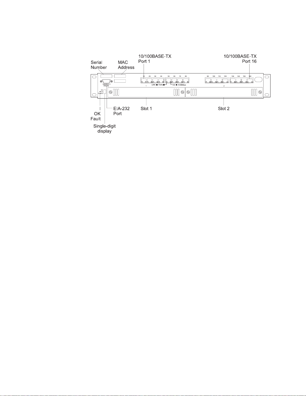
Front Panel
Figure 1. Front Panel of the 8275-416 .
8275-416 LEDs
8275-416 LEDs are located at the lower left corner of the front panel (left of
the single-digit display and are identified with a vertical bar (I), OK, and
Fault. The LED for the vertical bar is Green, as is the OK LED; the Fault
LED’s color is amber. The states of the LEDs are on, off, or blinking, are
explained later in this chapter.
Single-Digit Display
The single digit display is located at the lower left corner of the front panel
as shown in Figure 2 on page 6. During diagnostics, the character displayed
indicates the diagnostic test being executed. Once the 8275-416 is
operational, the character displayed is its Unit ID.
Serial Port (EIA 232)
The serial port is a standard DB-9 male connector that provides an
EIA–232 serial interface (sometimes referred to as the out-of-band
management port). Use a null-modem serial cable when connecting to a
workstation (see “Appendix C. Cable Pinout Diagrams” on page 79). Use a
VT100 terminal emulator program to configure your terminal’s attached
COM port as follows:
v 19 200 baud
v 8 data bits
v 1 stop bit
v No parity
v Hardware flow control OFF
See “Chapter 2. Accessing the 8275-416” on page 11 for more information
about connectivity.
Ethernet 10/100BASE-TX Ports
The 8275-416 has 16 Ethernet 10/100BASE-TX ports. Each port has two
LEDs located at the lower right and left of the connector. Status indications
of the Port LEDs are explained later in this chapter.
Feature Module Slots 1 and 2
These feature modules are available to expand port connections to your
8275-416 :
Chapter 1. Introduction 5
Page 20
v 8-Port 10/100BASE-TX Ethernet Feature Module, IBM P/N 35L2355
v 8-Port 100BASE-FX Ethernet Feature Module, IBM P/N 35L2356
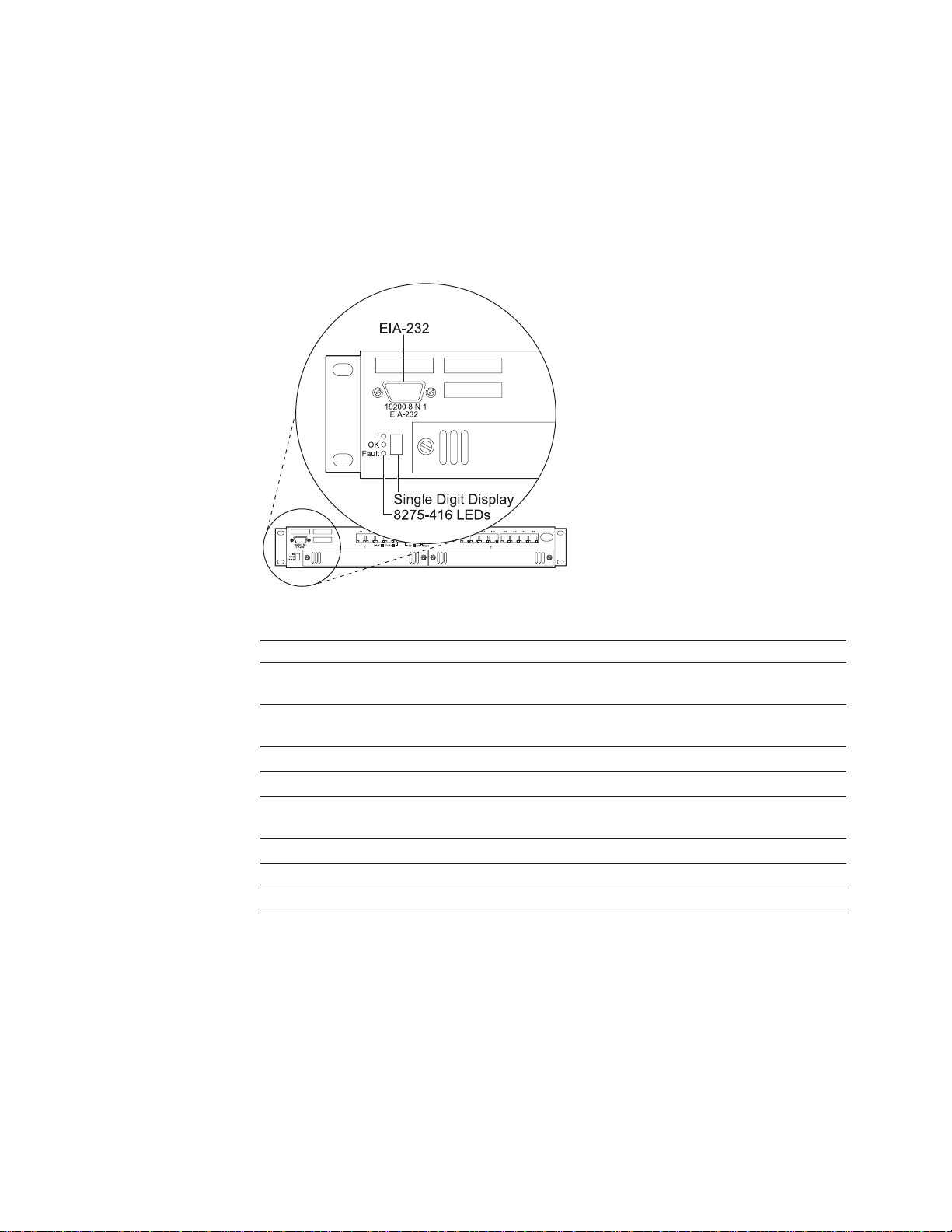
8275-416 Status LEDs
8275-416 Status LEDs are shown in Figure 2 and their indications are explained in
the table that follows:
Figure 2. Status LEDs for the 8275-416 .
LED Color State Explanation
I Green ON There is power to the 8275-416 and the
power supply is OK.
OFF There is no power is present, or there
is a power supply failure.
OK Green ON The 8275-416 is operational.
OFF The 8275-416 is not operational.
Blinking Operational code or configuration file
transfer is in process.
Fault Yellow ON Indicates a hardware fault.
OFF No hardware fault.
Blinking Diagnostics is in process.
6 8275-416 User’s Guide
Page 21
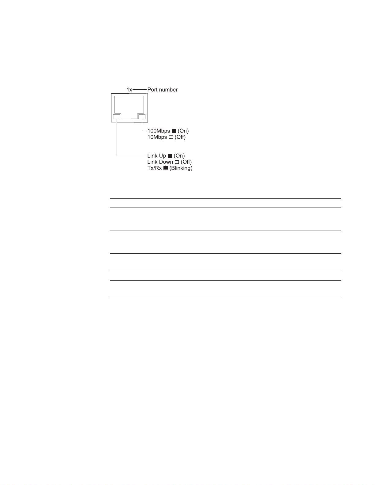
Ethernet Port LEDs
Port LEDs on the 8275-416 and the 10/100BASE-TX Ethernet feature module are
shown in Figure 3 and they are explained in the table that follows.
Figure 3. Port Status LEDs for the 8275-416 and the 10/100BASE-TX Ethernet Feature
Module.
LED Color State Explanation
Right Ethernet
Port LED
Left Ethernet Port
LED
Green ON Indicates a 100 Mbps port. This LED
being On only has meaning if the link
is up.
OFF Indicates a 10 Mbps port. This LED
being Off only has meaning if the link
is up.
Green ON Link is up.
OFF Link is down.
Blinking Transmitting (Tx) and Receiving (Rx)
traffic.
Chapter 1. Introduction 7
Page 22
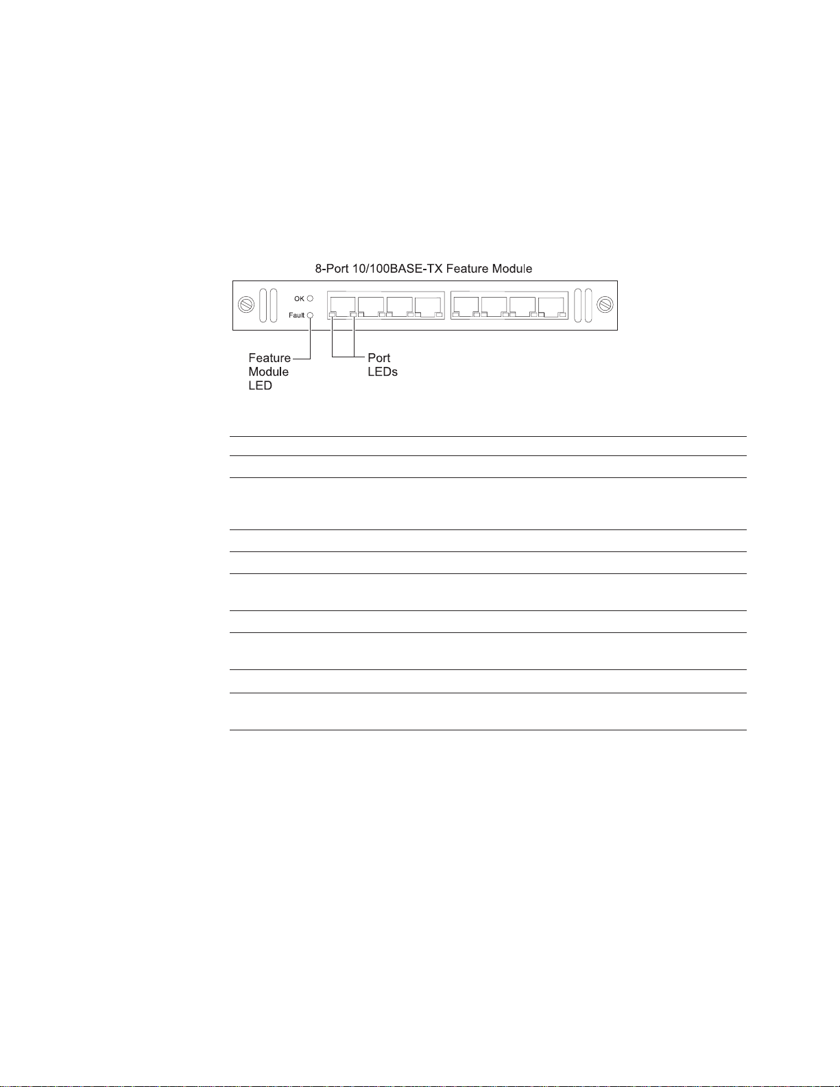
Feature Module LEDs
Each feature module has an OK and a Fault LED located at the left side of the
faceplate. The OK LED is Green and the Fault LED is amber. These LEDs are
shown in Figure 4 and Figure 5 on page 9. They indicate the status of the feature
module and are explained in the table that follows.
Status LEDs for the 10/100BASE-TX Ethernet Feature Module
Figure 4. Status LEDs for the 10/100BASE-TX Ethernet Feature Module.
LED Color State Explanation
OK Green ON There is power to feature module.
Fault Yellow ON There is a module fault.
Right Ethernet
Port LED
Left Ethernet Port
LED
OFF There is no power to feature module,
no power to the 8275-416 , or the
module has failed.
OFF There is no module fault.
Green ON Indicates a 100 Mbps port.
OFF Indicates a 10 Mbps port.
Green ON Link is up.
OFF Link is down.
Blinking Transmitting (Tx) and Receiving (Rx)
traffic.
8 8275-416 User’s Guide
Page 23

Status LEDs for the 100BASE-FX Ethernet Feature Module
Figure 5. Status LEDs for the 100BASE-FX Ethernet Feature Module.
LED Color State Explanation
OK Green ON There is power to the feature
module.
OFF There is no power to the feature
module, no power to the 8275-416
or the module has failed.
Fault Yellow ON There is a module fault.
OFF There is no hardware fault.
Port LED Green ON Link is up.
OFF Link is down.
Blinking Transmitting (Tx) and receiving (Rx)
traffic.
Physical Characteristics
Physical characteristics for the 8275-416 are summarized in the following table:
Characteristic Specification
Physical Dimensions
Weight (estimate) 6.0 kg (13 lb)
Service Clearance
Height 63.0 mm (2.48 in.) 1.5 EIA rack units
Width 440.0 mm (17.16 in.)
Depth 355.6 mm (14 in.)
Front Minimum of 15.3 mm (6 in.) for
cooling, cables, and to view LEDs
Sides Minimum of 50 mm (2 in.) for cooling
Rear Minimum of 15.3 mm (6 in.) for
cooling and power cord
Chapter 1. Introduction 9
Page 24

Characteristic Specification
Operating Environment
Operating Temperature
10° - 40° C (50° - 104° F)
Operating Humidity
8% - 80%
Storage Temperature
1° - 60° C (33.8° - 140° F)
Storage Humidity
8% - 80%
Shipment Temperature
40°C - 60°C (104°F - 140°F)
Shipment Humidity
5% - 100%
10 8275-416 User’s Guide
Page 25

Chapter 2. Accessing the 8275-416
You have several ways to physically make connection (connectivity) and access the
8275-416 . Once connected, you will want to initially configure the IP information
(either through the terminal interface or through DHCP or BootP), then choose
which user interface you want to use to manage it. Therefore, all interfaces support
configuring the 8275-416 and obtaining information from it, thus providing greater
flexibility in how you manage your 8275-416 . This chapter explains the ways you
can connect to your 8275-416 .
Connectivity Methods
There are two connectivity methods used to physically access the 8275-416 :
v Out-of-band connectivity, in which access to the 8275-416 is through the EIA 232
port.
v In-band connectivity, which is the ability to access the 8275-416 from a remote
station using the Ethernet network
Table 2 outlines the user interfaces that are available depending on your method of
connectivity.
Table 2. Connectivity Methods and Available User Interfaces
Connectivity Method Available User Interface
Out-of-band Terminal interface via the EIA 232 port
In-Band
(terminal directly attached, or remotely
attached to modem)
v Terminal interface via Telnet
v SNMP-based management interface
v Web-based management interface
Out-of-Band Connectivity
Out-of-band connectivity lets you access your 8275-416 through the EIA 232 port. It
can be either through a locally attached PC (personal computer) running VT100
terminal emulation software, or through a remotely attached PC running VT100
terminal emulation software.
Locally Attached Terminal
To establish out-of-band connectivity using a locally attached terminal, make the
physical connections and set up using the following procedure:
1. Attach one end of a null-modem cable to the EIA 232 port of the 8275-416 as
shown in Figure 6 on page 12, and the other end to the COM port of your PC
(see “Appendix C. Cable Pinout Diagrams” on page 79).
© Copyright IBM Corp. 1999 11
Page 26
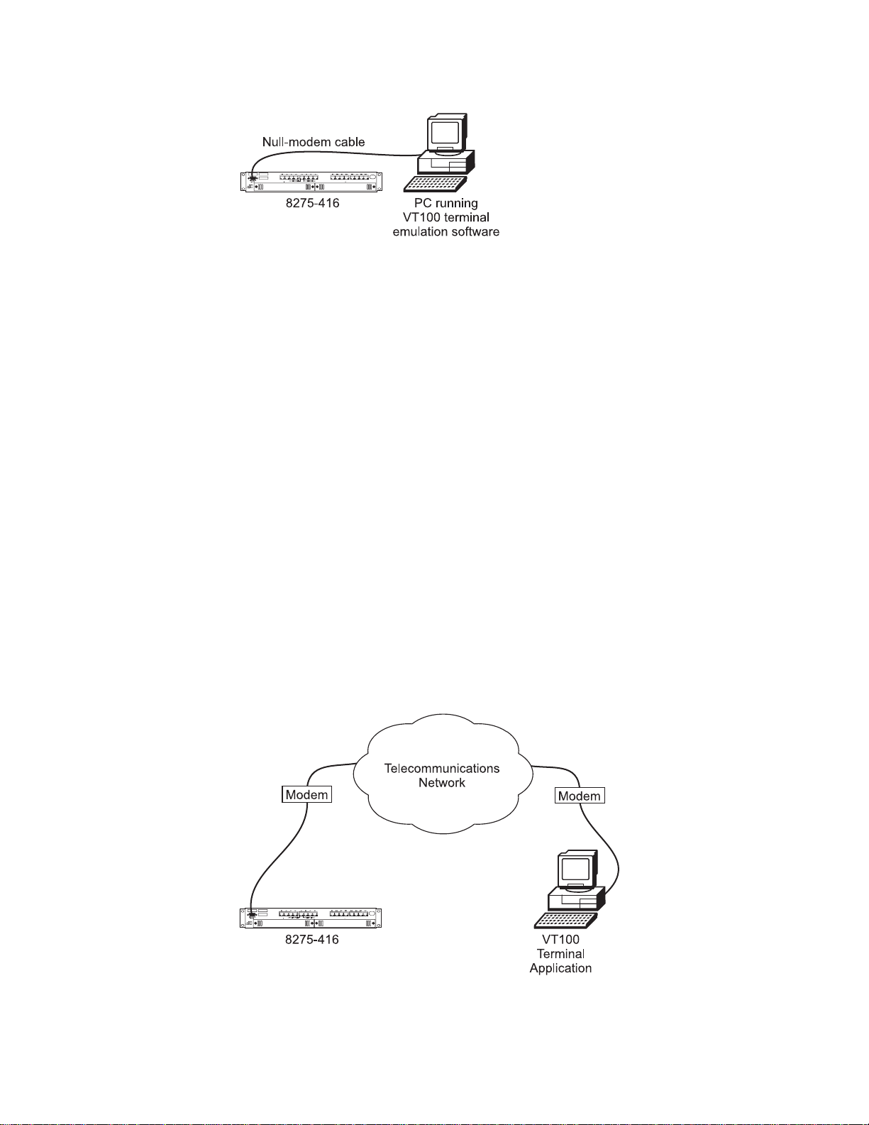
Figure 6. Out-of-Band Connectivity — Locally Attached Terminal
2.
Configure the VT100 terminal emulation application as follows:
v Baud rate: 19200
v Parity: None
v Data bits: 8
v Stop bits: 1
v Flow control: None
3. Log in to the terminal interface. The terminal interface requires you to log in with
a user name and password. The user name must have Read/Write status. The
admin
default user name is:
4. See “Appendix D. Interface Conventions for the Console” on page 83 for a
description of terminal interface key definitions. You may need to configure your
terminal emulation application to enable use of these keys.
, and the password is blanks (no password).
Remotely Attached Terminal
To establish out-of-band connectivity using a remotely attached terminal, make the
physical connections using the following procedure:
1. Unpack the modem and install it according to the manufacturer’s instructions.
2. Attach one of the serial cable (not provided) to the EIA 232 port of the 8275-416
and the other end to your modem as shown in Figure 7.
12 8275-416 User’s Guide
Figure 7. Out-of-Band Connectivity — Remotely Attached Terminal
3. Set up the modem that is attached to the 8275-416 by following these steps:
Page 27

a. Connect the other end of the cable to the modem.
b. Configure the modem to use the same settings as those on your 8275-416 .
v Baud rate: 19200
v Parity: None
v Data bits: 8
v Stop bits: 1
v Flow control: None
c. Set up the remote modem and terminal.
d. Configuration command syntax varies from modem to modem. Make sure
that the modem has the following characteristics:
v Asynchronous mode
v Disable modem response
v Disable flow control (for example, AT \Q)
v Disable echo (for example, AT Q1)
v Autoanswer mode on second ring (for example, AT SO=2)
e. Setup the remote modem and terminal.
f. After configuring the modem, save the configuration.
g. Establish a modem link as described in the modem user documentation.
h. Log in to the terminal interface. The terminal interface requires you to log in
with a user name and password. The user name must have Read/Write
admin
status. The default user name is:
password).
i. See “Appendix D. Interface Conventions for the Console” on page 83 for a
description of terminal interface key definitions. You may need to configure
your terminal emulation application to enable use of these keys.
, and the password is blanks (no
4. In order to use in-band connectivity, the 8275-416 must be configured with IP
information (IP address, subnet mask, and default gateway). You can configure
IP information initially by using either of these methods:
v DHCP or BootP
v Terminal interface via the EIA 232 port.
5.
To configure the IP information, see “Chapter 3. Configuring your 8275-416” on
page 17 for details.
In-Band Connectivity - Telnet, Web, SNMP
Note: In order to use in-band connectivity, you must configure the 8275-416 with its
IP information (IP address, subnet mask, and default gateway). See
“Chapter 3. Configuring your 8275-416” on page 17 for configuring BootP or
DHCP and IP information for your 8275-416 .
In-band connectivity allows access to the 8275-416 using the data network (as
shown in Figure 8 on page 14).
Chapter 2. Accessing the 8275-416 13
Page 28
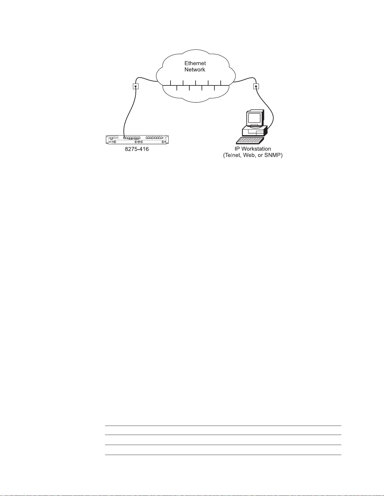
Figure 8. In-Band Connectivity
Terminal Interface - Telnet
Telnet console management can be performed through an Ethernet port (In-band
connectivity). You must configure an Ethernet IP address before using Telnet
console management (Refer to “Chapter 3. Configuring your 8275-416” on page 17
for initially configuring IP information for your 8275-416 .
You can use any Telnet application that emulates a VT100 terminal to establish a
Telnet Console management session. Up to five concurrent Telnet sessions are
supported. For security, the Telnet session can be automatically logged off after a
certain time of inactivity. You configure the time of inactivity from 0 to 60 minutes;
the default is 5 minutes.
The terminal interface is menu driven and can be used to manage the 8275-416
through the EIA 232 port or a Telnet session. For security, a log in userid and
password is required. Multiple userids and associated passwords can be created.
Two levels of access privileges are supported: read/write and read-only.
See “Appendix D. Interface Conventions for the Console” on page 83 for a
description of the terminal keys. You may need to configure your terminal
application to enable use of these keys.
See “Chapter 4. Using the Terminal Interface” on page 25 for a description of the
terminal interface panels.
14 8275-416 User’s Guide
SNMP-Based Management Interface
The 8275-416 has an SNMP agent that supports SNMP Version 1 which allows it to
be managed by any SNMP-based application (for example, Nways Campus
Manager which supports the MIBs that the 8275-416 supports). MIBs supported by
the 8275-416 are shown in Table 3.
Table 3. MIBs Supported by the 8275-416 .
MIBs Supported
MIB-II (RFC 1213)
Definitions of Managed Objects for Bridges (RFC 1493)
Page 29

Table 3. MIBs Supported by the 8275-416 . (continued)
MIBs Supported
IEEE 802.3 Ethernet MIB (RFC 1643)
RMON MIB (RFC 1757)
IBM 8275-416 MIB
The SNMP-based application must specify the appropriate community name that
the 8275-416 is configured to support. Real-time trap messages can be configured
to be sent to designated trap receivers. All configuration information on the switch
has read/write access via SNMP. All status information is also available via SNMP.
See “Chapter 4. Using the Terminal Interface” on page 25 for details about SNMP
support for the 8275-416 .
Web-Based Management Interface
The 8275-416 has a Web server that supports HTTP 1.1 and HTML 3.2 or later.
The Web browser must support HTTP 1.1 or HTML 3.2 or later.
The Web interface provides an interface to access and change 8275-416
parameters. Menus similar to those available through the terminal interface are also
displayed by the Web browser. To access the 8275-416 from a Web browser, you
must have configured the IP information for the 8275-416 . You will need a valid log
in userid and password. The accepted userids and passwords are the same as
those configured for the terminal interface.
See “Chapter 5. Using the Web Interface” on page 61 for starting and using the web
interface.
Chapter 2. Accessing the 8275-416 15
Page 30

16 8275-416 User’s Guide
Page 31

Chapter 3. Configuring your 8275-416
After hardware installation, you must configure the IP address for your 8275-416 for
it to be fully manageable in your network with the factory-default configuration. You
might want to change some of the defaults at a later time.
First, you need to decide how you will access your 8275-416 . See “Chapter 2.
Accessing the 8275-416” on page 11 for details about in-band and out-of-band
connectivity. It is assumed that when you come to this chapter you will already have
established connectivity.
Configuring IP information
IP information can be initially assigned either through:
v DHCP or BootP (the default), or
v Terminal interface through the EIA 232 serial port.
Your 8275-416 can be configured from remote locations using DHCP (Dynamic
Host Configuration Protocol) or BootP. BootP (documented in RFC 951 and RFC
1542) is a bootstrap protocol used by a diskless workstation to learn its IP address,
the location of its boot file, and the boot server name. The 8275-416 supports
“reserved” or static DHCP, documented in RFC 1541.
If you are using DHCP or BootP, the DHCP or BootP server must be configured
with the appropriate information for the 8275-416 . If you are not using BootP or
DHCP, set the Network Configuration Protocol with a value of
network traffic.
When you use DHCP or BootP to get the 8275-416 ’s IP information, you configure
the Network Configuration Protocol by selecting Server Configuration Menu from
the Management Menu in the Terminal interface, and by defining the values as
shown in Figure 9 on page 18:
None
to reduce
© Copyright IBM Corp. 1999 17
Page 32
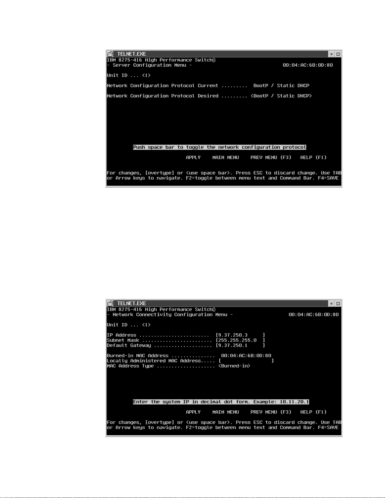
Figure 9. Configuring BootP/Static DHCP.
Network Configuration Protocol Desired
When you select BootP/Static DHCP (the default), the 8275-416 periodically
sends requests to a BootP or DHCP server until a response is received.
None When you select None, you must manually configure the 8275-416 with the
appropriate IP information.
To manually configure the IP information using the terminal interface, select
Network Connectivity Configuration Menu from the Management Menu. Then,
specify the information as described in the following text on the panel as shown in
Figure 10
18 8275-416 User’s Guide
Figure 10. Configuring Network Connectivity (IP Information).
Page 33

You must configure the following IP information to establish in-band connectivity
(access through SNMP, Telnet, and Web interfaces) with the 8275-416 :
IP Address
Unique IP address of your 8275-416 . Each IP parameter is made up of
four decimal numbers. The numbers range from 0 to 255. The default for all
IP parameters are
Subnet Mask
Specifies the subnet mask for the LAN.
Default Gateway
If the 8275-416 is a node outside the IP range of the LAN.
Burned-in MAC Address
The burned-in MAC address is the default MAC address used.
Locally Administered MAC Address
A locally administered MAC address for the 8275-416 is an additional
parameter that you can configure. The following rules apply when specifying
a locally administered MAC address:
v Bit 6 of byte 0 (called the U/L bit) indicates whether the address is
universally administered (B‘0’) or locally administered (B‘1’).
v Bit 7 of byte 0 (called the I/G bit) indicates whether the destination
address is an individual address (B‘0’) or a group address (B‘1’).
v A locally administered address must have bit 6 On (B‘1’) and bit 7 Off
(B‘0’).
zeros
(that is, 0.0.0.0).
MAC Address Type
The burned-in MAC address is the default MAC address type.
Concepts About Making Configuration Changes
This section provides key concepts about making configuration changes, getting the
changes put into effect, and retaining the changes across a power cycle of the
8275-416 .
This chapter provides you specific information about making configuration changes
using the Terminal interface, Web interface, and the SNMP interface.
Making Configuration Changes
Configuration changes are made by entering data for one or more items.
Error checking is done on the data entered to ensure that it is valued before it is
processed, When the check is done and the result depends on the method used to
initiate the change.
Configuration changes made by one user are also seen by other users when the
same data is requested. Be aware that information displayed may be old data if the
latest information is not requested prior to making any changes.
Processing Configuration Changes
Once you make a configuration change and it is accepted, the change is not put
into effect until you issue an APPLY command. Apply makes the changes take
Chapter 3. Configuring your 8275-416 19
Page 34

effect, but the changes are not automatically retained across a reset or power cycle.
SAVE makes the changes take effect and also result in the changes being retained
across a reset or power cycle.
Saving Configuration Changes Across a Reset or Power Cycle
In order for configuration changes to be retained across a reset or power cycle, you
must issue a SAVE command.
Making Configuration Changes via the Terminal Interface
This section provides information about making configuration changes, getting the
changes put into effect, and retaining the changes across a power cycle when using
the Terminal Interface.
Making Configuration Changes
On the terminal interface menus, field entries that can be modified are surrounded
by either square brackets ([ ]) or angle brackets (< >).
Square brackets identify an item that can be changed by typing in text. As soon as
you begin typing, the current value of the field is erased and is replaced by the new
text. In other words, no insert or overwrite modes can be performed in the field. You
can use the following special keys while you are editing text fields:
v Arrow keys: Arrow keys are ignored when you are editing a text field. On a field
where no modifications have been made, arrow keys are used to move the
cursor to the appropriate field indicated by the direction of the arrow key pressed.
v Back Space: Removes a character in front of the cursor.
v Delete: Gives the same result as the Backspace.
v Enter: The text is accepted and the cursor moves to the next field. On a text field
where no modifications have been made, Enter moves the cursor to the next
field.
v ESC: Stops editing the field and restores the original data.
v Space Bar: May be an allowable key to enter text.
v Tab: Performs the same function as the Enter key.
v F4: Represents SAVE. Causes the configuration data to be saved and also
applied if not already done.
20 8275-416 User’s Guide
Angle brackets identify an item that can be changed by selecting the desired option.
The following special keys are used while selecting a configuration option:
v Arrow keys: The text is accepted and the cursor moves to the appropriate field
indicated by the direction of the arrow key pressed. On a field where no
modifications have been made, arrow key just moves the cursor to the
appropriate field.
v Enter: The text is accepted and the cursor moves to the next field. On a field
where no modifications have been made, Enter moves the cursor to the next
field.
v ESC: Stops modifying the field and restores the original data.
v Space Bar: Displays the next possible value for this field. Used to cycle through
the available options to select the desired value.
v Tab: Performs the same function as the Enter key.
Page 35

v F4: Represents SAVE. Causes the configuration data to be saved and also
applied if not already done.
When processing data entered in a text field, all leading and trailing whitespace
characters are ignored (such as, space, Tab, ESC).
Once a configuration change is made and is accepted (the cursor is no longer on
the field that was modified), the change is not put into effect until you issue an
APPLY.
Applying (Processing) Configuration Changes
Note: To help you know when a configuration change needs to be applied, as soon
as the first change is accepted, “APPLY” appears on the Command Bar.
When you select APPLY, the following occurs:
v All configuration changes associated with this panel are processed, that is,
syntax checking is performed on the data, if applicable, and if that is successful,
the configuration change is put into effect (processed).
v If invalid configuration data was entered (such as, data value is out of the
supported range), none of the changes on the panel have been processed yet
and an error message is displayed identifying the field containing the error.
Invalid data errors are reported one field at a time. All configuration changes
must be valid before any of the changes are processed.
v If the configuration change is processed successfully and UNSAVED DATA is not
already displayed on the upper right corner of the panel, then UNSAVED DATA is
displayed.
v APPLY no longer appears on the panel
If you make configuration changes and then exit a panel without applying the
changes, your changes are lost. For example, the following results in losing any
changes made on the panel:
v You make configuration changes on the current panel and your select any of the
following commands:
– MAIN MENU
– PREV MENU
– HELP MENU
– NEXT PAGE
– PREV PAGE
v You make configuration changes on the current panel and you select a different
slot or port.
Note: Configuration changes are not automatically retained across a reset or a
power cycle. To retain changes, you must issue a SAVE command as
described in the following section.
Saving Configuration Changes Across a Reset or Power Cycle
For configuration changes to be retained across a reset or power cycle, you need to
issue a SAVE command. Configuration changes made via the terminal interface can
be permanently saved by either:
v Pressing the F4 (Save) key.
Chapter 3. Configuring your 8275-416 21
Page 36

v Selecting Save Applied Changes on the System Utilities Menu.
As a reminder that there are configuration changes that need to be saved,
“UNSAVED DATA” appears in the upper right corner of the panel. Once you issue a
SAVE, the following happens:
1. SAVING DATA appears on the panel while the 8275-416 is in the process of
permanently saving the current operational configuration data.
2. DATA SAVED appears on the panel when the 8275-416 completes saving the
current operational configuration.
3. UNSAVED DATA no longer appears on the panel until the next configuration
change is made.
If you issue a SAVE without previously having made an Apply for recently made
configuration changes, the changes are automatically applied when the SAVE is
issued.
If you initiate a reset of the switch without permanently saving previously made
configuration changes, you are prompted with a message to continue without saving
the configuration change.
Making Configuration Changes via the Web Interface
This section provides information on making configuration changes, getting the
changes put into effect, and retaining the changes across a power cycle when using
the Web Interface.
Making Configuration Changes
On the Web pages, field entries that can be modified are displayed in a box with a
white background. Depending on the field being modified, you can modify the text
by:
v Typing in the appropriate text over existing text (overwriting). If the data typed in
is syntactically incorrect, the data entered is rejected and the original data is
displayed.
v Selecting an option from one of the items displayed when the pull-down menu is
selected. All items in a pull-down menu are syntactically correct.
Until the Apply or Save button is selected, you can restore any modified values to
their original data by selecting the Undo button.
Processing Configuration Changes
Once the desired fields are modified, select the Apply button or Save button to
process the changes. Apply makes the changes take effect but the changes are not
automatically retained across a reset or power cycle. Save makes the changes take
effect and also results in the changes being retained across a reset or power cycle.
Before the Web Browsers sends the request to the switch, the data for the fields
changed are verified. If any field is invalid, an error message is displayed identifying
the field that contains the error. Invalid data errors are reported one field at a time.
All configuration changes must be valid before any of the changes are sent.
22 8275-416 User’s Guide
Page 37

If you make configuration changes and then change the page without Applying or
Saving the changes, the changes are not processed.
Saving Configuration Changes Across a Reset or Power Cycle
In order for configuration changes to be retained across a reset or power cycle, you
must issue a SAVE command. Configuration changes can be permanently saved by
either of these actions:
v Clicking the SAVE button.
v Going to the System Utilities Menu and selecting Save All Applied Changes.
Making Configuration Changes via SNMP
This section provides information on making configuration changes, getting the
changes put into effect, and retaining the changes across a power cycle when using
SNMP.
Making Configuration Changes
You make configuration changes via SNMP by issuing SNMP Set commands to
MIB objects that the 8275-416 supports as read-write.
Processing Configuration Changes
When the SNMP Set is received, the 8275-416 checks the data to ensure that it is
valid. If it is invalid, the SNMP error code BADVALUE is returned in the SNMP Set
Response. Otherwise, the configuration change is processed and put into effect.
Saving Configuration Changes Across a Reset or Power Cycle
Configuration changes made via SNMP Set commands are not automatically
retained across a reset or power cycle. To get these changes retained across a
reset or power cycle, you must issue a SAVE. This can be done via the 8275-416
private MIB using swDevCtrlSaveConfiguration.
Chapter 3. Configuring your 8275-416 23
Page 38

24 8275-416 User’s Guide
Page 39

Chapter 4. Using the Terminal Interface
This chapter describes the 8275-416 terminal interface. To use the terminal
interface it would be helpful to have skills and experience in using Ethernet
networking products and to be familiar with networking concepts such as IP device
management, bridging, switching, and collecting/evaluating trap and monitoring data
The terminal interface panels are automatically refreshed every few seconds to
provide you with current information.
Note: The panels shown in this chapter are intended to be representative and
should not be assumed to be entirely accurate because they are subject to
change before shipment of the product.
Login Panel
The Login panel is the first panel displayed when initializing the terminal interface.
Figure 11 shows the Login panel; you need an approved user name and password
to log in.
Figure 11. Log In Panel for Terminal Interface
User Name Can be up to 8 alphanumeric characters in length. The value is not
case sensitive. The default is admin for a read/write user, and
guest is the default for a read only user.
Password Can be up to 8 alphanumeric characters in length. The value is not
case sensitive. The default is all blanks (blanks indicate no
password).
The terminal interface provides a way to logout. Either use the LOGOUT command
on the Main Menu or from the Main Menu, select System Utilities Menu, then
select Logout. When you have finished using the terminal interface, ensure you
have saved all configuration changes before logging out.
© Copyright IBM Corp. 1999 25
Page 40

The Main Menu
Following a successful login, the Main Menu appears (see Figure 12). Information
following in this section is arranged in the order of topics on the Main Menu.
Figure 12. Main Menu for Terminal Interface
System Information Menu
Management Menu
Device Configuration
Statistics Menu
User Account Management
System Utilities
System Information
The 8275-416 manages information about the hardware and software version
installed in the 8275-416 . System information contains read only and read/write
fields. The read only fields are written when the 8275-416 is manufactured. Through
configuration you can change only the read/write fields:
Location
effective. A reset is not necessary for the changes to be effective.
Allows access to information that is maintained about the 8275-416 .
Contains selections associated with managing the 8275-416 .
Contains selections associated with configuring the 8275-416 .
Contains selections for access to statistical data that is gathered for the
8275-416 .
Allows you to define users and passwords and their level of access.
Allows selection of the utilities available with the 8275-416 .
System Name,System
and
System Contact
. Changes to these fields must be saved to be
26 8275-416 User’s Guide
Page 41

To access system information, select System Information Menu on the Main
Menu. By selecting Inventory Information Menu and System Description Menu,
you can view information about your 8275-416 .Figure 13 shows your system
information options.
Figure 13. System Information Menu
Inventory Information
Figure 14 shows you inventory information available for your 8275-416 .
Figure 14. Inventory Information
Chapter 4. Using the Terminal Interface 27
Page 42

System Description
Figure 15 shows you a system description for your 8275-416 .
Figure 15. System Description
28 8275-416 User’s Guide
Page 43

Management
Select Management Menu on the Main Menu (SeeFigure 16.) to use the
management functions of the 8275-416 .
Figure 16. Management Menu
Configuring the 8275-416 for Network Connectivity
To configure the IP information using the terminal interface, select Network
Connectivity Configuration Menu from the Management Menu. The Network
Connectivity Configuration Menu appears as shown in Figure 17.
Figure 17. Network Connectivity Configuration
Chapter 4. Using the Terminal Interface 29
Page 44

You must configure the following IP information to establish in-band connectivity to
8275-416 :
IP Address
Unique IP address for your 8275-416 . Each IP parameter is made up of
four decimal numbers. The numbers range from 0 to 255. The default for all
IP parameters are
Subnet Mask
Specifies the subnet mask for the LAN.
Default Gateway
If the 8275-416 is a node outside the IP range of the LAN.
Burned-in MAC Address
The burned-in MAC address is the default MAC address used.
Locally Administered MAC Address
A locally administered MAC address for the 8275-416 is an additional
parameter that you can configure. The following rules apply when specifying
a locally administered MAC address:
v Bit 6 of byte 0 (called the U/L bit) indicates whether the address is
universally administered (B‘0’) or locally administered (B‘1’).
v Bit 7 of byte 0 (called the I/G bit) indicates whether the destination
address is an individual address (B‘0’) or a group address (B‘1’).
v A locally administered address must have bit 6 On (B‘1’) and bit 7 Off
(B‘0’).
zeros
(that is, 0.0.0.0).
MAC Address Type
The burned-in MAC address is the default MAC address type.
Configuring Serial Port
The 8275-416 allows you to access the 8275-416 through the serial EIA 232 port.
This type of connectivity is called
direct local attach, or remote attached through a locally attached modem. See
“Chapter 2. Accessing the 8275-416” on page 11 for descriptions of ways to access
the 8275-416 .
On the Main Menu, select Management Menu. From the Management Menu,
select Serial Port Configuration Menu. Figure 18 on page 31 shows the
parameters to configure the serial EIA 232 port.
Out-of-band connectivity
. Attachment can be
30 8275-416 User’s Guide
Page 45

Figure 18. Serial Port Configuration
You specify Login Timeout and Baud Rate:
Serial Port Login Timeout:
Specifies the maximum connect time without console activity. The value is
in a range from 0 to 160 minutes. A value of 0 indicates that a console can
be connected indefinitely. The default value is 5 minutes.
Baud Rate :
Specifies the communication rate of the terminal interface. Values can be
1200, 2400, 4800, 9600, 19200, 38400, 57600, or 115200. The default
value is 19200.
Configuring for DHCP or BootP Server
If you do not want to manually configure the 8275-416 with IP information, the
8275-416 can obtain the IP information from a BootP or DHCP server. When BootP
or DHCP is enabled, the 8275-416 periodically send out requests until a response
is received from either a DHCP or BootP server. The IP information in the BootP or
DHCP response overlays any existing IP information in 8275-416 . The new IP
information is not retained across a reset until a SAVE is issued.
DHCP
To configure static DHCP, you must specify an IP address that will be assigned to
the 8275-416. This IP address is mapped to the 8275-416’s MAC address. The
static DHCP does not obtain an IP address from a pool of addresses on a DHCP
server unless one is explicitly set up for a given MAC address. For example, In
Windows NT, a reservation must be set up for the 8275-416’s MAC address. It
should be assigned an IP address from the pool of current addresses. The router,
IP address, and subnet mask should all be configured for the 8275-416’s MAC
address. No other DHCP options are supported other than gateway/router address,
IP address, subnet mask.
Chapter 4. Using the Terminal Interface 31
Page 46

BootP
For BootP, the BootP server must have the appropriate information configured for
the 8275-416 . A newly installed 8275-416 broadcast a BootP request over IP when
it is powered on or reset. The BootP server, using information from its BOOTPTAB
file, provides the 8275-416 with configuration information. In addition to obtaining
the IP address and the subnet mask, the 8275-416 can attach to a configuration
server to obtain a configuration file. The configuration file is an ASCII file containing
8275-416 commands. The commands are executed as soon as the configuration
file is transferred via TFTP to the 8275-416 . The 8275-416 updates its
configuration file with the information contained in the BootP message. The
following is an example of a BOOTPTAB file entry containing configuration
information for the 8275-416 :
8275_416_Switch_1:ht=ethernet:ha=0004ac6b0980:\
ip=10.1.7.7:gw=10.1.1.1:\
sm=255.255.255.0
8275_416_Switch_2:ht=ethernet:ha=0004ac6b09C0:\
ip=10.1.7.8:gw=10.1.1.1:\
sm=255.255.255.0
Where:
ht hardware type
ha host hardware address
ip host IP address
gw gateway address list
sm subnet mask
Configuration information obtained from the BootP server is not saved unless you
issue the SAVE command. Next, configure the Network Configuration Protocol.
Configuring 8275-416 for DHCP or BootP Server
If you are using DHCP or BootP, the DHCP or BootP server must be configured
with the appropriate information for the 8275-416 .
If you are not using BootP or DHCP, set the Network Configuration Protocol with a
None
value of
When you use DHCP or BootP to get the 8275-416 ’s IP information, you configure
the Network Configuration Protocol by selecting Server Configuration Menu from
the Management Menu. The Server Configuration Menu is shown in Figure 19 on
page 33.
to reduce network traffic.
32 8275-416 User’s Guide
Page 47

Figure 19. Server Configuration
Define one of the following values:
Unit ID
Network Configuration Protocol Desired
Configuring SNMP
The 8275-416 has an SNMP agent that complies with SNMP Version 1 (SNMPV1).
For more about the SNMP specification, see the appropriate SNMP RFCs. The
SNMP agent sends traps through TCP/IP to an external SNMP manager based on
your SNMP configuration. SNMP configuration for the 8275-416 includes configuring
the trap receiver and SNMP community parameters, which are described in the
following text.
Configuring the SNMP Community
The SNMP agent must be configured with a community name for the 8275-416 . A
community name is a name associated with the 8275-416 and with a set of SNMP
managers allowed to manage it with a specified privileged level. You can add,
change or delete communities. The 8275-416 does not have to be reset for
changes to take effect. Up to six communities are simultaneously supported.
Up to 8 alphanumeric characters which identifies the 8275-416 .
When you select BootP/Static DHCP (the default), the 8275-416 periodically
sends requests to a BootP or DHCP server until a response is received. If
you are not using BOOTP or DHCP, set the Network Configuration Protocol
None
with a value of
to reduce network traffic.
To configure your SNMP communities, select SNMP Community Configuration
Menu from the Management Menu. Figure 20 on page 34 shows SNMP community
information you need to specify.
Chapter 4. Using the Terminal Interface 33
Page 48

Figure 20. SNMP Community Configuration
SNMP Community Name:
Name identifies each SNMP community and can be a string up to 32
characters. A
private
communities have default values. The default names are Public and
Private. You can replace these default community names with unique
identifiers for each community. The default value for the remaining four
community names are blank.
Access Mode:
This value can be read only or read/write. A community with a read only
access allows for 8275-416 information to be displayed. A community with a
read/write access allows for configuration changes to be made and for
information to be displayed.
Client IP Address
This attribute is an IP address (or portion thereof) from which this device
will accept SNMP packets with the associated community. The requesting
entity’s IP address is combined with the Client IP Mask before being
compared to the Client Ip Address. Note: If the Client IP Mask is set to
0.0.0.0, a Client IP Address of 0.0.0.0 matches all IP addresses.
Client IP Mask
This attribute is a mask to be combined with the requesting entity’s IP
address before comparison with Client IP Address. If the result matches
with Client IP Address then the address is an authenticated IP address . For
example, if the Client IP Address is 9.47.128.0 and the corresponding Client
Ip Mask is 255.255.255.0, a range of incoming IP addresses would match,
ie the incoming IP addresses could be a value in the following range:
9.47.128.0 - 9.47.128.255.
community is for users who have read/write access. Two
public
community means users have read only access. A
34 8275-416 User’s Guide
Status:
This attribute has the following values: Enable, Disable and Delete on the
Terminal and Web interface and Active, Inactive, and Delete via SNMP. A
status value of Enable/Active means that the community is active, allowing
SNMP managers associated using this community to manage the
Page 49

Roadrunner according to its access right. A status value of Disable/Inactive
means that the community is not active; no SNMP requests using this
community will be accepted. In this case the SNMP manager associated
with this community cannot manage the 8275-416 until the Status is
changed back to Enable/Active. A status value of Delete means that this
name will be removed from the table. The default Status values for the
default private and public communitiy names are both Enable/Active. The
default value is Disable/Inactive for remaining four communities.
Configuring the Trap Receiver
Trap messages are sent across a network to an SNMP Network Manager. These
messages alert the manager to events occurring within the 8275-416 or on the
network. Up to six simultaneous Trap Receivers are supported.
To configure Trap Receivers, select SNMP Trap Receiver Configuration Menu on
the Management Menu. Figure 21 shows the parameters you need to specify.
Figure 21. SNMP Trap Receiver Configuration
Trap Receiver parameters are:
SNMP Community Name:
The SNMP community name of the remote network manager. The name
can be up to 32 characters. The default value is “blank”.
IP Address:
Each IP address parameters is four decimal numbers. The numbers range
from 0 to 255. The default IP address is 0.0.0.0.
Status:
The status for trap receivers can be Enabled, Disabled, or Deleted. Trap
receivers with enabled status are active and the SNMP agent sends traps
to them. Trap receivers with disable status are inactive the SNMP agent
does not send traps to them. Trap receivers with a deleted status are
removed from the table.
Chapter 4. Using the Terminal Interface 35
Page 50
Configuring Traps
Configuring Trap Conditions
You can optionally configure which traps that the 8275-416 should generate. You do
this by selecting a status for the trap condition, that is, if it is either enabled or
disabled. If a trap condition is enabled and the condition is detected, 8275-416 ’s
SNMP agent sends the trap to all enabled trap receivers. Otherwise, no condition is
detected and no trap is sent. The default Status value for all Trap Conditions is
Enabled. The 8275-416 does not have to be reset to implement the changes. Warm
start and cold start traps are always generated; there are no associated trap
conditions.
To configure trap conditions, select Trap Menu from the Management Menu, the
select you condition to configure from the Trap Menu. Your choices are viewing the
trap log, enabling/disabling trap flags, and checking the trap log status.
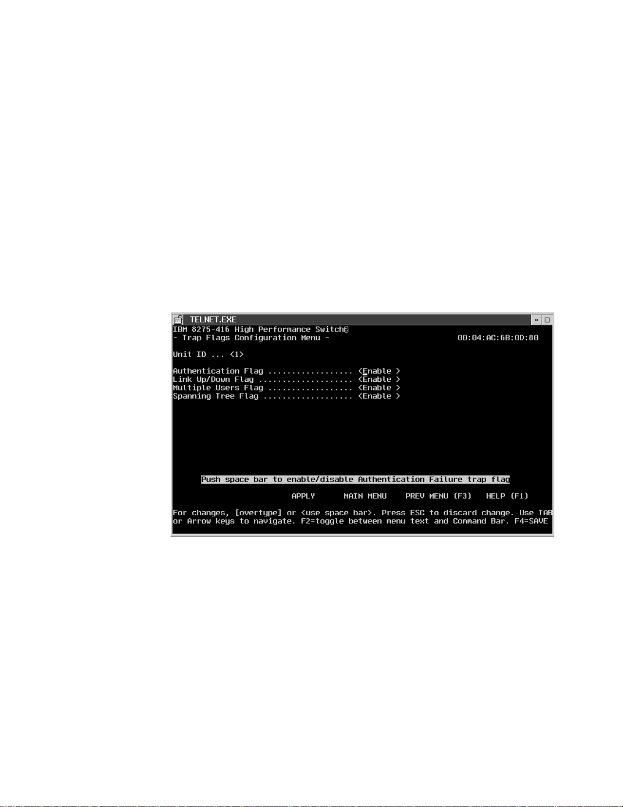
Figure 22 shows the trap flags that you can set.
36 8275-416 User’s Guide
Figure 22. Trap Flags Configuration
The following are the definitions of the Trap Conditions:
Authentication Failure:
Enable/Disable authentication traps.
Link Up/Down:
Enable/Disable Link Up/Link Down traps.
Multiple Users:
Enable/Disable Multiple User traps.
Spanning Tree:
Enable/Disable Spanning Tree traps.
Page 51

Trap Log
The 8275-416 maintains a Trap Log; it contains a maximum of 64 entries which
wrap. Select Trap Menu from the Management Menu, then select Trap Log Menu
from the Trap Menu. Figure 23 shows the entries in the trap log.
Figure 23. Trap Log
Each entry contains:
System Up Time:
This entry shows how long the system has been continuously operational.
Trap: This entry is the name (a 16-byte character string) of the trap condition;
which are:
v Warm Start
v Cold Start
v Authentication Failure
v Link Up
v Link Down
v Multiple Users
v New Spanning Tree Root
v Spanning Tree Topology Change
The following are valid operations of Trap Log:
Display:
The newest to oldest traps are listed. Use this operation to view all Trap
Log entries.
Clear: This operation empties Trap Log. Use this operation to clear the Trap Log.
Trap Log information is not retained across a switch reset.
Chapter 4. Using the Terminal Interface 37
Page 52

Checking Trap Log Status
By selecting Trap Menu from the Management Menu, then selecting Trap Log
Status Menu from the Trap Menu, you can check the status of how many traps that
have been generated. You can choose to clear the trap log on this panel (see
Figure 24.
Figure 24. Trap Log Status
Configuring Telnet
You can manage the 8275-416 remotely using a Telnet connection. “Chapter 2.
Accessing the 8275-416” on page 11 describes setting up a Telnet connection. To
configure for Telnet, select Management Menu from the Main Menu, then from the
Management Menu, select Telnet Configuration Menu (see Figure 25 on page 39).
38 8275-416 User’s Guide
Page 53

Ping
Figure 25. Telnet Configuration
The following parameters are for configuring a Telnet session with the 8275-416 :
Telnet Login Timeout
A session is active as long as the session has not remained idle for the
value set. Specify a decimal value from 0 to 160 minutes. A value of 0
indicates that a Telnet session remains active indefinitely. The default is 5
minutes.
Maximum Number of Telnet Sessions
Specify a decimal value from 0 to 5. If the value is 0, no telnet session can
be established. The default value is 5.
Allow New Telnet Sessions:
Specify a value of Yes or No. A value of Yes means that new telnet
sessions will be establish until there are no more sessions available. A
value of No means that no new telnet session are to be established. If there
are no sessions at the moment, and you indicate that the value is to be
applied or saved, then no Telnet connections are allowed. Any already
established session remains active until the session is ended or an
abnormal network error ends it. The default value is Yes.
The 8275-416 provides a Ping utility that can be used to check connectivity
between devices in a network. To use ping, the 8275-416 must be configured
correctly for network (in-band) connectivity. The source and target devices must
have the ping utility enabled and running on top of TCP/IP. The 8275-416 can be
pinged from any IP workstation (as long as there is a physical path between the
8275-416 and the workstation). The terminal interface allows you to send one ping,
three pings or a continuous ping to the target station.
To use Ping, select Management Menu from the Main Menu. Then select Ping
Menu from the Management Menu (see Figure 26 on page 40).
Chapter 4. Using the Terminal Interface 39
Page 54

ARP Cache
Figure 26. Ping
You must supply this information:
IP Address:
The IP address of the target station. The value is 4 decimal bytes ranging
from 0 to 255. The default is 0.0.0.0.
Ping Count:
You can select one of these values; the default value is single:
v Single — one ping is sent to target station.
v Multiple — three pings are sent to the target station.
v Continuous — a ping is sent every second.
Command:
Send is the only command. To stop sending pings, press F3 (PREV MENU)
or select the Main Menu when sending continuous pings.
Select Management Menu from the Main Menu. Then, select ARP Cache Menu
from the Management Menu to displays the ARP cache for the 8275-416 .
This is used to check connectivity between the 8275-416 and other devices. The
ARP cache identifies the MAC address of the IP stations communicating with the
8275-416 . SeeFigure 27 on page 41 for ARP Cache information.
40 8275-416 User’s Guide
Page 55

Figure 27. ARP Cache
Chapter 4. Using the Terminal Interface 41
Page 56

Device Configuration
To configure the 8275-416 , select Device Configuration Menu on the Main Menu.
Figure 28 shows your options.
Figure 28. Device Configuration
Configuring the 8275-416
Address Aging Timeout
The 8275-416 allows you to set a time after which its address will timeout; the
address aging timeout. This value can be set by selecting Device Configuration
Menu from the Main Menu, then selecting Switch Configuration Menu (see
Figure 29 on page 43).
42 8275-416 User’s Guide
Page 57
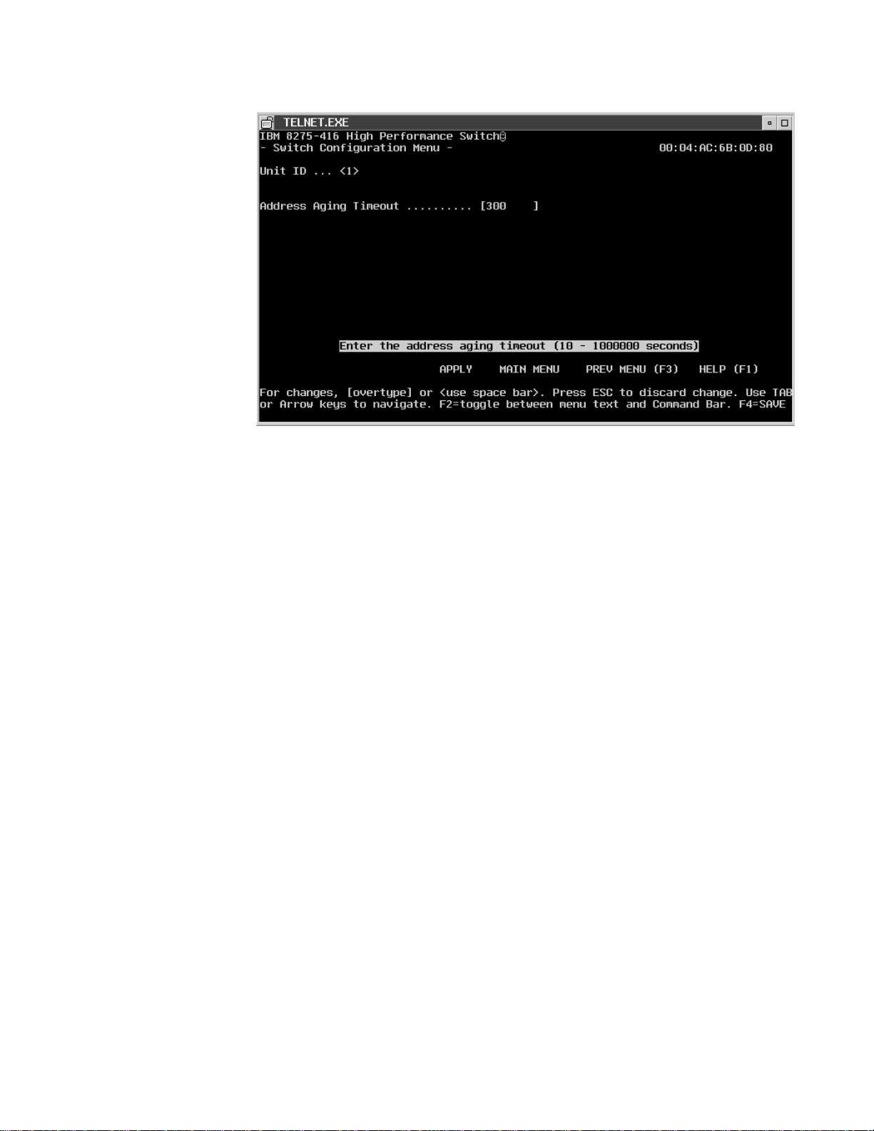
Figure 29. Switch Configuration
The value you specify is:
Address Aging Timeout
The value can be in a range from 0 — 1,000,000 (seconds). The default is
300 (seconds).
Configuring Ports
The 8275-416 is shipped from the factory with default port settings that allow it to
automatically determine the port type and speed.
See “Chapter 3. Configuring your 8275-416” on page 17 for details about making
and saving configuration changes.
You can configure the ports by selecting Device Configuration Menu from the
Main Menu, then by selecting Port Configuration Menu from the Device
Configuration Menu. (see Figure 30 on page 44).
Chapter 4. Using the Terminal Interface 43
Page 58

Figure 30. Port Configuration
You can select or change the following values:
Slot The 16 base ports are associated with slot 0. A feature module in Slot 1 or
Slot 2 have ports 1-8 associated with them.
Port Indicates the port number. Ports are identified by a slot and port number.
The slot and port number are separated by a period (.). The base set of
ports are considered to be on slot 0. The feature slots are Slot 1 and Slot 2.
For each slot, the ports are numbered 1 to 8. Since there are 16 base
ports, each 8275-416 has ports 0.1 to 0.16. Ports on a feature module
located in Slot 1 are numbered 1.1 to 1.8, and ports on a feature module in
Slot 2 are numbered 2.1. to 2.8.
Admin Mode
This value indicates if the port is Enabled or Disabled. The default for all
ports is Enabled. At start-up, each port is reset and the spanning tree state
reported is Disabled until the Link is Up. The 8275-416 ensures that the
station is at the correct speed and duplex setting, turns on the port LED
that indicates Link is Up. Once the Link is up, the port transmits and
receives frames and participates in the spanning tree protocol as defined by
the spanning tree configuration.
Physical Mode
The value of Auto (autodetect) is valid only for 10/100BASE-TX ports.
44 8275-416 User’s Guide
Link Trap
This value can be Enabled or Disabled. It allows you to enable traps by
port.
read only fields
The read only fields are:
v STP- indicates if the port participates in Spanning Tree Protocol (STP)
v Physical Status - indicates if port is full-duplex or half-duplex.
v Link Status - indicates if the port link is up or down.
v IfIndex - When using SNMP, the interface index (ifIndex) is sometimes
used to identify the specific interface being addressed. On a 8275-416 ,
Page 59

each Ethernet port is an interface and so is the IP Agent being used for
managing it (which is also referred to as the Management Interface).
v The value returned for ifNumber in the MIB-II Interface table does not
include the Management Interface (that is, the value of ifNumber only
reflects the number of ports in the switch). If there are 32 ports, ifNumber
will incorrectly be 32 instead of being 33.
v Port ifIndex Values - The ifIndex values for the 8275-416 ports start with
1 and increment by 1 for each port physically in the box. Each ifIndex
value maps, one for one, with an Ethernet port.
v Example scenarios:
– if there are 32 ports (16 base ports, 8 ports in slot 1, 8 ports in slot 2)
- ifIndex 1 is slot 0, port1
- ifIndex 9 is slot 0, port 9
- ifIndex 17 is slot 1, port 1
- ifIndex 25 is slot 2, port 1
– if there are 24 ports (16 base ports, 8 ports in slot 2)
- ifIndex 1 is slot 0, port1
- ifIndex 9 is slot 0, port 9
- ifIndex 17 is slot 2, port 1
The Management Interface always has an ifIndex of 1000.
Port MAC Address
Each port is automatically configured with a burned-in MAC address. This
address is used as the source address of spanning tree frames and may be
used in 802.3x PAUSE frames for the 8275-416 .
Configuring Port Monitoring
Any of the Ethernet ports can be selected as a probe to monitor forwarded traffic
(not local traffic) with an external network analyzer. The selected probe port can
monitor (mirror) traffic from one port.
From the Main Menu, select Device Configuration Menu. Then, select Port
Monitoring Menu from the Device Configuration Menu. (See Figure 31 on
page 46.)
Chapter 4. Using the Terminal Interface 45
Page 60

Figure 31. Port Monitoring
Specify values for the following parameters:
Port Monitoring:
Used to
Disable.
Monitoring Port:
This is the
that a Network Analyzer is attached to. The slot can be 0, 1 or 2. The
default is 0. The port range is 1 to 16 for Slot 0; 1-8 for Slots 1 and 2.
Port to be Monitored:
This is the port from which data is captured and sent to the monitoring port;
the port under analysis. The port range is 1 to16 for Slot 0; 1-8 for Slots 1
and 2.
EnableorDisable
slot.port
that the
the port monitoring function. The default is
monitored
Configuring Spanning Tree Protocol (STP)
Spanning Tree Switch Configuration/Status
The 8275-416 participates in Spanning Tree Protocol (STP). STP allows you to
configure redundant paths in the switch topology, and have the 8275-416
automatically blocks redundant paths to prevent loops (fault tolerant). If an active
path is broke and a backup path is available, the 8275-416 finds the redundant path
and enables it (fault tolerant). Without STP, a path failure means loss of connectivity
for the affected part of the network, forcing manually established connectivity or
redundant loops in the network.
data is sent to. This is the
slot.port
46 8275-416 User’s Guide
The 8275-416 complies with the IEEE 802.1D standard. Refer to the IEEE 802.1D
document for STP specifications. 8275-416 supports one STP for the entire switch.
You can configure the Spanning Tree Protocol for the 8275-416 . Select Device
Configuration Menu from the Main Menu. Then select Spanning Tree Switch
Page 61
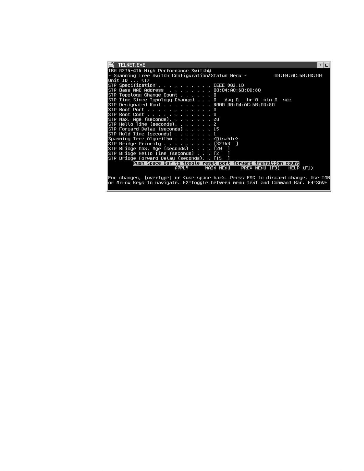
Configuration/Status from the Device Configuration Menu. (See Figure 32 .)
Figure 32. Spanning Tree Switch Configuration/Status
The following section lists and describes the STP configuration functions and
related parameters.
Spanning Tree Algorithm:
Indicates if the 8275-416 participates in Spanning Tree Protocol. A status of
Enable means that 8275-416 participates in the STP. Disable means that
8275-416 does not participate in the STP. The default is Enable.
Bridge Priority:
Decimal value which indicates the priority of the 8275-416 . This value
ranges from 0 to 65535. The default value is 32768. The lower the value,
the higher the priority. The 8275-416 with the lowest priority value becomes
root
the
(IEEE 802.1D). The default is 32768.
Maximum Age Time:
When the 8275-416 is
which the configuration message used by the Spanning Tree Algorithm is
discarded. The range is between 6 to 40 seconds. The default value is 20
seconds.
Hello Time:
When the 8275-416 is
8275-416 waits before sending the next configuration message. The value
is range between 1 and 10 seconds. The default value is 2 seconds.
Forward Delay Time:
This value specifies the time spent in ″Listening and Learning″ mode before
forwarding packets. The range is between 4 to 30 seconds. The default is
15 seconds.
root
, Maximum Age Time is the time in seconds after
root
, Hello Time is the time in seconds that the
Cost: This output is automatically calculated. The cost represents the shortest
distance from any switch to the root switch interval for the unit announcing
Chapter 4. Using the Terminal Interface 47
Page 62

its presence on the network. The range is between 0 to 65,535. The default
value is 0. If Status is Enable, the 8275-416 participates in the Spanning
Tree Protocol.
Spanning Tree Port Configuration/Status
You can configure the Spanning Tree Protocol by ports. Select Device
Configuration Menu from the Main Menu. Then select Spanning Tree Port
Configuration/Status Menu from the Device Configuration Menu. (See Figure 33.)
Figure 33. Spanning Tree Port Configuration/Status
The parameter values are:
Port Priority:
Decimal value which indicates the priority of the 8275-416 . This value
ranges from 0 to 255. The lower the value, the higher the priority. The
8275-416 with the lowest priority value becomes the
The default is 128.
Port Path Cost:
This output is automatically calculated. The cost represents the shortest
distance from any switch to the root switch interval for the unit announcing
its presence on the network. The range is between 0 to 65535. The default
value starts at 0, then it is 100 for 10Mbps ports; and it is 19 for 100Mbps
ports.
Configuring Broadcast Storm Recovery
Select Device Configuration on the Main Menu. Then, from the Device
Configuration Menu, select Broadcast Storm Recovery Menu. Broadcast storm
recovery can be enabled or disabled; the default is Disable. (See Figure 34 on
page 49.)
root
(IEEE 802.1D).
48 8275-416 User’s Guide
Page 63
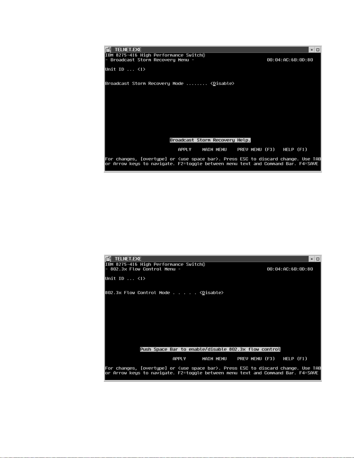
Figure 34. Broadcast Storm Recovery
Configuring 802.3x Flow Control
Select Device Configuration on the Main Menu. Then, from the Device
Configuration Menu, select 802.3x Flow Control Menu. 802.3x Flow Control can
be enabled or disabled; the default is Disable. (See Figure 35.)
Figure 35. 802.3x Flow Control
Chapter 4. Using the Terminal Interface 49
Page 64

Statistics
To access statistics, select Statistics Menu on the Main Menu. Traffic statistics are
kept by port. Details and summaries of packets broadcast, transmitted, and
switched, as well as, error packets and discarded packets are the types of statistics
kept for your 8275-416 .
After making your selection, the screens containing statistics will refresh every few
seconds. The following panels represent examples of the types of statistics that you
can select from the Statistics Menu.
Port Summary Statistics
See Figure 36 for a summary of port statistics.
Figure 36. Port Summary Statistics
Port Detailed Statistics
See Figure 37 on page 51 for a summary of port statistics.
50 8275-416 User’s Guide
Page 65

Figure 37. Port Detailed Statistics
Management Statistics
See Figure 38 for a summary of port statistics.
Figure 38. Management Statistics
Chapter 4. Using the Terminal Interface 51
Page 66

User Account Management
On the Main Menu, select User Account Management Menu.Figure 39 shows the
data entry screen for specifying your user names, passwords, and access mode.
Figure 39. User Account Management Menu
The 8275-416 allows you to add and delete users and set user passwords for the
8275-416 . You are to provide the following information:
User Name:
User name can be up to eight alphanumeric characters. The User Name is
not case sensitive. Up to six user names (accounts) can be defined; one
with read/write access mode and five with read only access mode.
Password:
The password can be up to eight alphanumeric characters and is not case
sensitive. A blank password indicates no password. The default value is
blank.
Confirm Password:
The confirm password can be up to eight alphanumeric characters. The
confirm password is not case sensitive. A blank confirm password indicates
no password. The default value is blank.
Access Mode:
This value is not configurable. User access mode can be:
read/write
Only one user can be defined with read/write access mode per
8275-416 . This user can change the status of other users, add and
delete users, change passwords and change configurations, and
use system utilities.
52 8275-416 User’s Guide
read only
Up to five users can be defined with read only access mode per
8275-416 . The message of read only appears on configuration
screens when a read only user is logged in.
Page 67
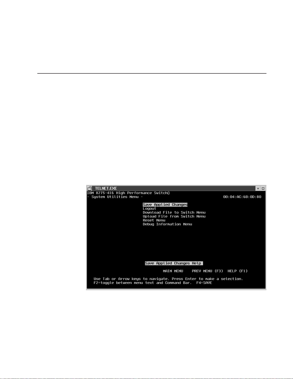
Status:
Status can be Enable, Disable or Delete. Enable means that the user name
is authorized to access the 8275-416 . Disable means that the user name is
not allowed to access the 8275-416 . Delete means the user will be
removed from the list upon an apply or save.
System Utilities
The system utilities can be used only by users with read/write access. You can use
the system utilities by selecting System Utilities Menu on the Main Menu.
Figure 40 shows the available utilities.
Saving Applied Changes
There are two ways to save applied changes which result in the changes being
retained across a reset:
v Pressing the F4 key.
v Selecting Save Applied Changes on the System Utilities Menu.
You can permanently save configuration changes by pressing the F4 key or going
to the System Utilities Menu and selecting Save Applied Changes, as shown in
Figure 40.
Logging Out
Figure 40. Save Applied Changes Menu
When you have finished using the terminal interface, ensure you have saved and
applied all configuration changes before you Logout. The terminal interface provides
an orderly way to logout. One way is to use the Logout command on the Main
Menu. Another way to Logout is to select System Utilities Menu from the Main
menu, then select Logout as shown in Figure 41 on page 54.
Chapter 4. Using the Terminal Interface 53
Page 68

Handling Files
Figure 41. Logout Utility
To upload or download a file, select System Utilities Menu from the Main Menu.
Then make the appropriate selection from the System Utilities Menu.
The 8275-416 can download or upload files. Downloading is the transfer of files
from a remote server into the 8275-416 . Uploading is the transfer of files from the
8275-416 to a remote server.
Configuration settings can be retrieved from the 8275-416 as a binary file. A binary
configuration file can be sent to the 8275-416 . This allows you to back up the
configuration or to easily update the configuration of multiple 8275-416 s.
Additionally, a configuration file may be provided to IBM support personnel for
problem determination.
The last-saved configuration used by the 8275-416 is retained after a code update
or a reset.
Downloading a File to the 8275-416
Downloading is the transfer of files from a remote server into the 8275-416 . (See
Figure 42 on page 55.)
54 8275-416 User’s Guide
Page 69

Figure 42. Downloading File to the 8275-416 .
Uploading a File from the 8275-416
Uploading is the transfer of files from the 8275-416 to a remote server. (See
Figure 43.)
Figure 43. Uploading File from the 8275-416 .
The following parameters apply to uploading and downloading of files.
File Type:
The file types are:
For Download
Chapter 4. Using the Terminal Interface 55
Page 70

v Code (the default)
v Configuration
For Upload
v Configuration
v Error log
v System trace
v Trap log (the default)
Upload or Download Mode
The mode is either XMODEM or TFTP. XMODEM is only valid when file
transfer is initiated via the serial EIA 232 port. The default value is
XMODEM.
Start Transfer Now:
You indicate Yes or No.
File Name:
The file name can be up to 16 alphanumeric characters. The 8275-416
remembers the last file name used. The default value is blank.
Note: File Name, File Path, and TFTP Server IP Address are applicable
only if the Transfer Mode is TFTP.
File Path:
The directory path where the file is located. The 8275-416 remembers the
last file path used. The default value is blank.
Reset Utility
TFTP Server IP Address:
The IP address of the server where the file is located. It is valid only when
the Transfer Mode is TFTP. The address is 4 decimal bytes ranging from 0
to 255. The default value is zeroes.
8275-416 allows you to reset the 8275-416 without powering off. Reset means that
all network connections are terminated and the boot code executes. The 8275-416
uses the stored configuration to initialize the 8275-416 . You are prompted for
confirmation if you want the reset to proceed. A successful reset is evidenced by
the LEDs on the 8275-416 .
After selecting Reset Menu from the System Utilities Menu, you are given the
choice of the resets you can request as shown Figure 44 on page 57.
56 8275-416 User’s Guide
Page 71

Figure 44. Reset Menu
Resetting System
Reset the system by indicating the particular unit as shown in Figure 45. You must
identify the 8275-416 to reset. None is the default.
Figure 45. Reset Menu
Resetting Configuration Data to Factory Default Values
8275-416 allows you to reset the configuration to factory default values without
powering off. The factory defaults are not restored until the 8275-416 is reset. The
Chapter 4. Using the Terminal Interface 57
Page 72

8275-416 is automatically reset when this command is processed. You are
prompted for confirmation if you want the reset to proceed.
Reset the configuration data to the factory defaults by indicating the particular unit
as shown in Figure 46. You must identify the 8275-416 to reset. None is the default.
Figure 46. Reset Configuration Data to Factory Defaults
Resetting Passwords to Factory Default Values
8275-416 allows you to reset user passwords to factory default values without
powering off. The factory defaults are not restored until the 8275-416 is reset. The
8275-416 is automatically reset when this command is processed. You are
prompted for confirmation if you want the reset to proceed.
Reset the passwords by indicating the particular unit as shown in Figure 47 on
page 59. You must identify the 8275-416 to reset. None is the default.
58 8275-416 User’s Guide
Page 73

Debug Utility
Figure 47. Reset Passwords to Factory Defaults
Select the Debug Menufrom the System Utilities Menu panel.
Note: Using the Debug function may alter the state of the 8275-416 and cause
unexpected results. The intended for use of this Debug function is for trained
personel only.
You are prompted to indicate if want to continue (Y=yes or N=no). If you press ″Y″,
the debug command line interface is used.
Debug utility is only valid via the EIA-232 interface; it does not work via Web or
telnet.
Chapter 4. Using the Terminal Interface 59
Page 74

60 8275-416 User’s Guide
Page 75

Chapter 5. Using the Web Interface
You can manage your 8275-416 through your Web browser and Internet
connection. This type of management is referred to as Web-based management.
The following are the basic requirements for Web browsers to access the 8275-416
:
v Support for HTML version 4.0, or later
v Support for HTTP version 1.1, or later
v Support for JavaScript version 1.2, or later
This chapter explains how to access the 8275-416 Web-based management panels
to configure and manage your 8275-416 .
It is important to note that there are equivalent functions offered in the Web
interface as in the terminal interface (that is, there are usually the same menus to
accomplish a task). For example, you log in, there is a Main Menu with the same
functions available, and so on. The only difference is that the panels are web-like in
design. So, if you have read “Chapter 3. Configuring your 8275-416” on page 17
and “Chapter 4. Using the Terminal Interface” on page 25, navigating the Web
interface will not be difficult. This chapter is a brief introduction to the Web interface.
Web Page Layout
A Web interface panel for the 8275-416 Web page consists of three frames. Frame
1, across the top, appears a banner graphic of the 8275-416 . Frame 2, at the
bottom-left displays a hierarchical-tree view. The tree consists of a combination of
folders, sub-folders, and configuration and status HTML pages. You can think of the
folders and sub-folders as branches and the configuration and status HTML pages
as leafs. Only the selection of a leaf (not a folder or sub-folder) will cause Frame 2
to display a new HTML page. A folder or sub-folder has no corresponding Frame 3
HTML page. Frame 3, the bottom-right frame, displays the currently selected device
configuration status or the user configurable information that you have selected
from the Tree View of Frame 2, or both. You can resize each of these frames.
There are no fixed-sized frames.
Starting the Web Interface
Note: You must configure the IP address of the 8275-416 before using the Web
interface.
Follow these steps to bring up the 8275-416 Web interface:
1. Enter the IP address of the 8275-416 in the address field of your Web browser
and press Enter.
2. Log in with your user name and password. Press Enter
3. The navigation tree is displayed in Frame 2, and the System Description Menu
is displayed in Frame 3. Make your selection by clicking on the appropriate item
in the navigation tree in Frame 2.
4.
© Copyright IBM Corp. 1999 61
Page 76

Commands
The following commands are used throughout the Web interface panels or the
8275-416 :
Undo Restores any changes made on the panel to their original value since the
last Apply or Save.
Save Implements and saves the changes you just made. Some settings may
require you to reset the system in order for them to take effect.
Apply Implements the changes you just made. Some settings may require you to
reset the system for them to take effect.
Refresh
The Refresh button that appears next to the Apply button in Web interface
panels refreshes the data on the panel.
Restart
Refreshes the list and displays the data starting at the beginning of the list.
Next Displays the next set of information in the list.
62 8275-416 User’s Guide
Page 77

Chapter 6. Troubleshooting and Obtaining Service
Diagnosing Problems
This chapter contains procedures that help you to troubleshoot problems with your
8275-416 and its connections to other devices.
Be sure you read “Appendix A. Safety Information” on page 67 before proceeding.
Obtaining Software
To obtain support information, including technical tips, current product information,
and code updates and fixes the 8275-416 , visit the IBM Networking Tech Support
page at:
http://www.networking.ibm.com/support
You may also subscribe to receive e-mail notifications about code updates, tips, and
FAQs for your 8275-416 .
Troubleshooting in a Network
The 8275-416 terminal interface, Web interface, and SNMP management agent give
you access to important statistics and other information about the network. To
obtain these statistics, see “Chapter 4. Using the Terminal Interface” on page 25
and “Chapter 5. Using the Web Interface” on page 61 and select the appropriate
screens.
Start of Troubleshooting Process
If one or more devices (such as workstations) connected to an 8275-416 are unable
to communicate with other devices in the network, use the following steps to start
the troubleshooting process:
1. Locate the 8275-416 to which the device is connected. Use the network sketch,
the label on the cable connected to the device, or other network records to help
you locate the 8275-416 .
2. Have available any documentation associated with the feature modules that are
installed on the 8275-416 .
3. If you have an EIA 232 console session set up, ( see “Chapter 2. Accessing the
8275-416” on page 11), you can use it to determine if diagnostics have been
completed correctly.
4. Observe the LEDs on the 8275-416 front panel. The location of these LEDs is
shown in Figure 2 on page 6 with explanations of the LED status conditions in
the accompanying table. Ignore the feature module LEDs at this time. Review
this information before proceeding with the troubleshooting process.
5. If the LED status are not OK, locate in Table 4 on page 64, the symptom that
best describes the communication problem and the LED status you observed.
Then go the section that contains the recommended actions for resolving the
problem and follow that procedure.
© Copyright IBM Corp. 1999 63
Page 78

Choosing a Troubleshooting Procedure
Use Table 4 to determine which troubleshooting procedure you should use. Unless
otherwise stated, references to the OK and Fault LEDs are those on the 8275-416 .
Table 4. Troubleshooting— Isolating Problems
Symtom and LED State Action
The Fault LED, the OK LED are off, and the fan is not
running.
The Fault LED is On. If the Fault LED is blinking,
diagnostics are in process.
None of the devices connected to the 8275-416 can
communicate , the Fault LED is Off and the Power (I)
LED is On.
A single device connected to the 8275-416 is having
trouble communicating.
A feature module Fault LED is On. Remove and replace the feature
Note: The term “segment” refers to a single cable or interconnected cables
between a port and the device at the other end.
Procedure A
Go to “Procedure A”
Go to “Procedure B”
Go to “Procedure C” on page 65
Go to “Procedure D” on page 65
module.
Procedure B
Use this procedure if all LEDs are Off:
1. Verify that the ac power outlet to which the 8275-416 power supply is connected
is active. If an uninterruptible power supply (UPS) is being used to provide ac
power, ensure that the UPS is working correctly.
2. Verify that the power cord is installed correctly.
3. If the preceding conditions are satisfied, the power supply is defective. See
“Obtaining Service” on page 65.
Use this procedure if the Fault LED is On
1. Reset the 8275-416 by disconnecting the power cord from the outlet, waiting 10
seconds, and reconnecting the power cord to the outlet. If this corrects the
problem, resume using the 8275-416 .
2. One or more bad feature modules can cause this symptom, and the remaining
ports might continue to operate.
a. If you have feature modules, remove them.
b. Reset the 8275-416 .
c. If the 8275-416 comes up, reinstall the feature modules one at a time, and
reset the 8275-416 to determine the failing feature module.
3. If the problem is not corrected, the 8275-416 is defective. See “Obtaining
Service” on page 65.
64 8275-416 User’s Guide
Page 79

Procedure C
Procedure D
Use this procedure if all devices connected to the 8275-416 are having
communication problems, the Fault LED is Off and the OK LED is On:
1. Reset the 8275-416 by disconnecting the power cord from the outlet, waiting 10
seconds, and reconnecting the power cord to the ac outlet.
v If the problem goes away, resume using the 8275-416 .
v If the status LEDs indicate a failure, go to “Procedure B” on page 64.
v If the problem persists, check all the configuration parameters.
v If the problem has still not been resolved, go to “Procedure D” and try to get
individual ports working.
Use this procedure if one device connected to the 8275-416 is having a
communication problem, the Fault LED is Off, the OK LED is On and other attached
devices can communicate through the 8275-416 :
1. If the port LED is Off (left LED on 10/100BASE-TX port and single port LED on
100BASE-FX port), check the cable and the attached device. Check the
configuration settings to ensure they are OK.
2. If the port Link LED is On:
a. Check the port configuration and make sure the port admin mode is
Enabled.
b. If the above check is OK, try pinging the attached device from the 8275-416
. Make sure the 8275-416 is configured for in-band connectivity.
c. If ping is successfully received, go to Step 5.
d. If the ping is not received, go to Step 3.
3. Restart the communications program on the failed connected device.
v If the communications program appears to start without errors, observe the
port LED on the 8275-416 port. If it is On it might have gone away. Check the
port configuration parameters for possible causes of the failure.
v If the problem persists, go to Step 4.
4. For each device that is having a communication problem, connect its segment
to another identically configured Ethernet port on the 8275-416 . Try each of the
remaining ports to determine if the problem will go away.
v If the problem goes away, the problem might be in the 8275-416 . See
“Obtaining Service”.
5. The problem does not appear to be in the 8275-416 and the cables and devices
Obtaining Service
There are no user-serviceable parts inside the 8275-416 chassis. The 8-Port
10/100BASE-TX and 8-Port 100BASE-FX feature modules are individually
replaceable by the user.
v If the problem persists, continue with Step 5.
connected to the 8275-416 . The problem might be in the network applications
or other software running on the devices that are having the communication
problem. Refer to the networking software documentation for software problem
determination procedures, or consult your network administrator for assistance.
Chapter 6. Troubleshooting and Obtaining Service 65
Page 80

If you need assistance in troubleshooting or you need service for your 8275–416,
call IBM at:
v 1 800 772-2227 in the United States
v 1 800 426-7378 (1 800 IBM-SERV) in Canada.
v In other locations, contact your place of purchase.
Refer to your IBM Warranty for information concerning service for the product, or
contact the place where you purchased the product.
66 8275-416 User’s Guide
Page 81

Appendix A. Safety Information
Danger: Before you begin to install this product, read the safety information in
Caution: Safety Information—Read This First
safe procedures for cabling and plugging in electrical equipment.
Gevaar: Voordat u begint met de installatie van dit produkt, moet u eerst de
veiligheidsinstructies lezen in de brochure
SD21-0030. Hierin wordt beschreven hoe u electrische apparatuur op een
eerst,
veilige manier moet bekabelen en aansluiten.
Danger: Avant de procéder à l’installation de ce produit, lisez d’abord les consignes
de sécurité dans la brochure
préalable,
connecter les appareils électriques en toute sécurité.
SD21-0030. Cette brochure décrit les procédures pour câbler et
, SD21-0030. This booklet describes
PAS OP! Veiligheidsinstructies—Lees dit
ATTENTION: Consignes de sécurité—A lire au
Perigo: Antes de começar a instalar este produto, leia as informações de
segurança contidas em
Primeiro,
instalação de cabos e conexões em equipamentos elétricos.
© Copyright IBM Corp. 1999 67
SD21-0030. Esse folheto descreve procedimentos de segurança para a
Cuidado: Informações Sobre Segurança—Leia Isto
Page 82

Fare! Før du installerer dette produkt, skal du læse sikkerhedsforskrifterne i
Sikkerhedsforskrifter—Læs dette først
fremgangsmåde, du skal bruge ved tilslutning af kabler og udstyr.
Gevaar Voordat u begint met het installeren van dit produkt, dient u eerst de
veiligheidsrichtlijnen te lezen die zijn vermeld in de publikatie
Information - Read This First
voor het aansluiten van elektrische appratuur.
, SD21-0030. In dit boekje vindt u veilige procedures
SD21-0030. Vejledningen beskriver den
Caution: Safety
NB:
68 8275-416 User’s Guide
VAARA: Ennen kuin aloitat tämän tuotteen asennuksen, lue julkaisussa
Turvaohjeet—Lue tämä ensin
ohjeet siitä, miten sähkölaitteet kaapeloidaan ja kytketään turvallisesti.
Danger : Avant d’installer le présent produit, consultez le livret
Informations pour la sécurité — Lisez-moi d’abord
procédures à respecter pour effectuer les opérations de câblage et brancher les
équipements électriques en toute sécurité.
, SD21-0030, olevat turvaohjeet. Tässä kirjasessa on
Attention :
, SD21-0030, qui décrit les
Varoitus:
Page 83

Vorsicht: Bevor mit der Installation des Produktes begonnen wird, die
Sicherheitshinweise in
Achtung: Sicherheitsinformationen—Bitte zuerst lesen,
IBM
Form SD21-0030. Diese Veröffentlichung beschreibt die Sicherheitsvorkehrungen
für das Verkabeln und Anschließen elektrischer Geräte.
Vigyázat: Mielôtt megkezdi a berendezés üzembe helyezését, olvassa el a
Safety Information— Read This First,
SD21-0030 könyvecskében leírt biztonsági
Caution:
információkat. Ez a könyv leírja, milyen biztonsági intézkedéseket kell megtenni az
elektromos berendezés huzalozásakor illetve csatlakoztatásakor.
Pericolo: prima di iniziare l’installazione di questo prodotto, leggere le informazioni
relative alla sicurezza riportate nell’opuscolo
— Prime informazioni da leggere
in cui sono descritte le procedure per il cablaggio
Attenzione: Informazioni di sicurezza
ed il collegamento di apparecchiature elettriche.
Appendix A. Safety Information 69
Page 84

Fare: Før du begynner å installere dette produktet, må du lese
sikkerhetsinformasjonen i
SD21-0030 som beskriver sikkerhetsrutinene for kabling og tilkobling av elektrisk
utstyr.
Perigo: Antes de iniciar a instalação deste produto, leia as informações de
segurança
documento descreve como efectuar, de um modo seguro, as ligações eléctricas
dos equipamentos.
Cuidado: Informações de Segurança — Leia Primeiro
Advarsel: Sikkerhetsinformasjon — Les dette først
, SD21-0030. Este
,
70 8275-416 User’s Guide
Page 85

Peligro: Antes de empezar a instalar este producto, lea la información de
seguridad en
Atención: Información de Seguridad — Lea Esto Primero,
SD21-0030.
Este documento describe los procedimientos de seguridad para cablear y enchufar
equipos eléctricos.
Varning — livsfara: Innan du börjar installera den här produkten bör du läsa
säkerhetsinformationen i dokumentet
SD21-0030. Där beskrivs hur du på ett säkert sätt ansluter elektrisk
först,
Varning: Säkerhetsföreskrifter— Läs detta
utrustning.
Appendix A. Safety Information 71
Page 86

72 8275-416 User’s Guide
Page 87

Appendix B. Notices
References in this publication to IBM products, programs, or services do not imply
that IBM intends to make these available in all countries in which IBM operates. Any
reference to an IBM product, program, or service is not intended to state or imply
that only IBM’s product, program, or service may be used. Any functionally
equivalent product, program, or service that does not infringe any of IBM’s
intellectual property rights may be used instead of the IBM product, program, or
service. Evaluation and verification of operation in conjunction with other products,
except those expressly designated by IBM, are the user’s responsibility.
IBM may have patents or pending patent applications covering subject matter in this
document. The furnishing of this document does not give you any license to these
patents. You can send license inquiries, in writing, to:
IBM Director of Licensing
IBM Corporation
North Castle Drive
Armonk, NY 10504-1785
USA
Notice to Users of Online Versions of This Book
For online versions of this book, you are authorized to:
v Copy, modify, and print the documentation contained on the media, for use within
your enterprise, provided you reproduce the copyright notice, all warning
statements, and other required statements on each copy or partial copy.
v Transfer the original unaltered copy of the documentation when you transfer the
related IBM product (which may be either machines you own, or programs, if the
program’s license terms permit a transfer). You must, at the same time, destroy
all other copies of the documentation.
You are responsible for payment of any taxes, including personal property taxes,
resulting from this authorization.
THERE ARE NO WARRANTIES, EXPRESS OR IMPLIED, INCLUDING THE
WARRANTIES OF MERCHANTABILITY AND FITNESS FOR A PARTICULAR
PURPOSE.
Some jurisdictions do not allow the exclusion of implied warranties, so the above
exclusion may not apply to you.
Your failure to comply with the terms above terminates this authorization. Upon
termination, you must destroy your machine-readable documentation.
Electronic Emission Notices
Federal Communications Commission (FCC) Statement
This equipment has been tested and found to comply with the limits for a Class A
digital device, pursuant to Part 15 of the FCC Rules. These limits are designed to
provide reasonable protection against harmful interference when the equipment is
operated in a commercial environment. This equipment generates, uses, and can
radiate radio frequency energy and, if not installed and used in accordance with the
© Copyright IBM Corp. 1999 73
Page 88

instruction manual, may cause harmful interference to radio communications.
Operation of this equipment in a residential area is likely to cause harmful
interference, in which case the user will be required to correct the interference at
his own expense.
Properly shielded and grounded cables and connectors must be used in order to
meet FCC emission limits. IBM is not responsible for any radio or television
interference caused by using other than recommended cables and connectors or by
unauthorized changes or modifications to this equipment. Unauthorized changes or
modifications could void the user’s authority to operate the equipment.
This device complies with Part 15 of the FCC Rules. Operation is subject to the
following two conditions: (1) this device may not cause harmful interference, and (2)
this device must accept any interference received, including interference that may
cause undesired operation.
Industry Canada Class A Emission Compliance Statement
This Class A digital apparatus complies with Canadian ICES-003.
Avis de conformité aux normes d’Industrie Canada
Cet appareil numérique de la classe A est conform à la norme NMB-003 du
Canada.
European Norm (EN) Statement
This product is in conformity with the protection requirements of EU Council
Directive 89/336/EEC on the approximation of the laws of the Member States
relating to electromagnetic compatibility. IBM cannot accept responsibility for any
failure to satisfy the protection requirements resulting from a non-recommended
modification of the product, including the fitting of non-IBM option cards.
This product has been tested and found to comply with the limits for Class A
Information Technology Equipment according to CISPR 22/European Standard EN
55022. The limits for Class A equipment were derived from commercial and
industrial environments to provide reasonable protection against interference with
licensed communication equipment.
Warning: This is a Class A product. In a domestic environment this product may
cause radio interference in which case the user may be required to take adequate
measures.
Zulassungsbescheinigung laut dem Deutschen Gesetz über die
elektromagnetische Verträglichkeit von Geräten (EMVG) vom 30. August 1995
(bzw. der EMC EG Richlinie 89/336)
Dieses Gerät ist berechtigt in Übereinstimmung mit dem Deutschen EMVG das
EG-Konformitätszeichen - CE - zu führen.
74 8275-416 User’s Guide
Verantwortlich für die Konformitätserklärung nach Paragraph 5 des EMVG ist die
IBM Deutschland Informationssysteme GmbH, 70548 Stuttgart.
Page 89

Informationen in Hinsicht EMVG Paragraph 3 Abs. (2) 2:
Das Gerät erfüllt die Schutzanforderungen nach EN 50082-1 und EN 55022 Klasse A.
EN 55022 Klasse A Geräte müssen mit folgendem Warnhinweis versehen
werden:“Warnung: dies ist eine Einrichtung der Klasse A. Diese Einrichtung kann im
Wohnbereich Funkstörungen verursachen; in diesem Fall kann vom Betreiber
verlangt werden, angemessene Maßnahmen durchzuführen und dafür
aufzukommen.”
EN 50082-1 Hinweis:“Wird dieses Gerät in einer industriellen Umgebung betrieben
(wie in EN 50082-2 festgelegt), dann kann es dabei eventuell gestört werden. In
solch einem Fall ist der Abstand bzw. die Abschirmung zu der industriellen
Störquelle zu vergrößern.”
Anmerkung:Um die Einhaltung des EMVG sicherzustellen sind die Geräte, wie in
den IBM Handbüchern angegeben, zu installieren und zu betreiben.
Japanese Voluntary Control Council for Interference (VCCI) Statement
This product is a Class A Information Technology Equipment and conforms to the
standards set by the Voluntary Control Council for Interference by Information
Technology Equipment (VCCI). In a domestic environment this product may cause
radio interference, in which case the user may be required to take adequate
measures.
Korean Communications Statement
Please note that this device has been certified for business purpose with regard to
electromagnetic interference. If you find this is not suitable for your use, you may
exchange it for one of residential use.
Appendix B. Notices 75
Page 90

Taiwanese Class A Warning Statement
Class 1 Laser Statement
Class 1 Laser Product
Laser Klasse 1
Laser Klass 1
Luokan 1 Laserlaite
Appareil À Laser de Classe 1
To IEC 825-1:1993
Class 1 LED Statement
Class 1 LED Product
LED Klasse 1
LED Klass 1
Luokan 1 Ledlaite
Appareil À LED de Classe 1
To IEC 825-1:1993
Trademarks
76 8275-416 User’s Guide
IBM is a trademark of the International Business Corporation in the United States
and/or other countries.
Page 91

Other company, product, and service names may be trademarks or service marks
of other companies.
Appendix B. Notices 77
Page 92

78 8275-416 User’s Guide
Page 93
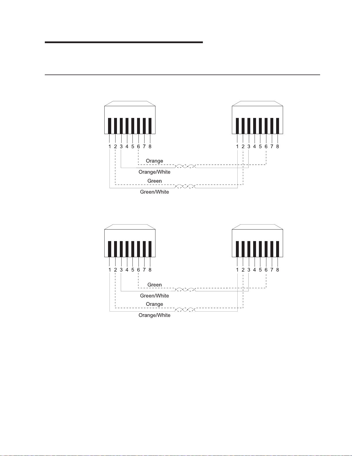
Appendix C. Cable Pinout Diagrams
This appendix specifies Ethernet and null-modem cable pinouts.
Straight-Through 10BASE-T/100BASE-TX Cables
Figure 48. Straight-Through UTP Cable (RJ-45 to RJ-45), T568A
Figure 49. Straight-Through UTP Cable (RJ-45 to RJ-45), T568B
© Copyright IBM Corp. 1999 79
Page 94

Straight-Through 10BASE-T/100BASE-TX Cables for STP
Figure 50. Straight-Through STP Cable (RJ-45 to IBM Data Connector)
Crossover 10BASE-T/100BASE-TX Cables
Figure 51. Crossover UTP Cable (RJ-45 to RJ-45), T568A
Figure 52. Crossover UTP Cable (RJ-45 to RJ-45), T568B
80 8275-416 User’s Guide
Page 95

Crossover 10BASE-T/100BASE-TX Cables for STP
Figure 53. Crossover STP Cable (RJ-45 to IBM Data ConnectorCrossover)
EIA-232 Port
Figure 54. Pinout of the EIA-232 Port
Appendix C. Cable Pinout Diagrams 81
Page 96

Null-Modem Cables
Figure 55. EIA-232 Modem Cable for Terminal with 25-Pin Connector
Figure 56. EIA-232 Modem Cable for Terminal with 9-Pin Connector
82 8275-416 User’s Guide
Page 97

Appendix D. Interface Conventions for the Console
Table 5 summarizes the meaning of special keys and commands that can be used
by the terminal interface. You may need to configure your VT100 terminal emulation
application to recognize some of these keys.
Active keys are clearly identified at the lower portion of each screen in the terminal
interface.
Table 5. Special Keys and Commands Used with the Terminal Interface
Special Keys/
Text/Commands
Brackets Identifies fields that can be modified.
Description
Angle (< >)
Field entries surrounded by angle brackets identify an item
that has a predifined set of options. Use the spacebar to
toggle through the available values. Pressing the Esc key
before moving off the field restores the current operational
value to the field. The change is not activated until Apply is
selected.
Square ([ ])
Field entries surrounded by square brackets identify an item
that can be changed by typing in text. Characters within a
text field cannot be modified using the cursor keys. No
insert or overwrite modes can be performed in the field. The
text in the field is erased and replaced by the new text.
Pressing the Esc key before moving off the field restores
the current operational value to the field. The change is not
activated until Apply is selected.
Arrow Keys Use to move between items within the menu body, within the
Command Bar, between the menu body and Command Bar. Up and
Down arrow keys move the cursor between lines. Right and Left
arrow keys move the cursor between columns. Arrow keys are
ignored when data is entered in a text field.
Right Arrow key
The right arrow key moves the cursor to the next field to
the immediate right.
Left Arrow key
The left arrow key moves the cursor to the previous field to
the immediate left.
Down Arrow key
The down arrow key moves the cursor vertically down to
the first character in the next row in the same position as
the original row or wraps to the next section of the menu.
Up Arrow key:
The up arrow key moves the cursor vertically up to the first
character in the previous row in the same position as the
original row or wraps to the next section of the menu.
© Copyright IBM Corp. 1999 83
Page 98

Table 5. Special Keys and Commands Used with the Terminal Interface (continued)
Special Keys/
Text/Commands
Tab Used to move to the next field.
Shift-Tab Not supported by VT100
Cntl-Tab Not supported by VT100
Back Space Used to remove the character in front of the cursor when entering
Blinking Text Warning or confirmation messages
Cursor The software does not have control over the cursor shape. Cursor
Delete Acts like the Backspace key in a text field
End Not supported
Enter Used to make a selection.
Esc When modifying field data enclosed in square backets ([ ]) or angle
Home Key Not supported
Insert Not supported
Spacebar When the cursor is on a modifiable field indicated by angle brackets,
Description
v When navigating between fields, Tab is used to move forward to
the next field and acts like the right arrow key.
v When in a text field which has been modified, Tab performs the
same function as the Enter key. When in a text field and no text
has been changed, Tab moves you to the next field.
text enclosed in square brackets.
shape is controlled by the terminal emulation.
v On a login screen and press Enter, the User ID and password are
processed for login.
v On a non-leaf menu option and press Enter, the selected menu is
displayed. (A non-leaf menu is a panel that contains a list of menu
names that can be selected.)
v On the Unit ID or Slot ID and press Spacebar, the item toggles
through the available values for that item. After a value is
determined, pressing Enter updates the screen with the
appropriate data for that Unit ID and Slot ID.
v On a field being modified and press Enter, the text is accepted
and undergoes syntax checking and the cursor is moved to the
next modifiable field.
v On a text field where no modifications have been made, Enter
moves the cursor to the next field.
brackets (< >), press Esc to stop modifying the field and go back to
the original data.
use the space bar to toggle through the options for that field. When
the cursor is on a modifiable field indicated by square brackets, the
space bar may be an allowable key to enter text.
84 8275-416 User’s Guide
Page 99

Table 5. Special Keys and Commands Used with the Terminal Interface (continued)
Special Keys/
Description
Text/Commands
Function keys
F1 Takes you to the Help Menu.
F2 Toggles between the menu body and the Command bar.
The first item is selected when toggling.
F3 Takes you back to the previous menu.
F4 This is the Save key and is used to save changed
configuration data. It is the same as going to the System
Utilities Menu and selecting Save Configuration Changes.
There is no undo after configuration changes have been
saved. Pressing F4 after making configuration changes
causes configuration changes to be automatically Applied
(F4 is used to Apply and Save configuration changes).
MAC Addresses
v MAC addresses are displayed and entered as 12 hexadecimal
digits in canonical format.
v Any alphabetic character (A-F) is displayed as uppercase. When
you enter the MAC address, upper and lower case characters are
accepted.
v Any illegal characters for a MAC address are not accepted.
Uppercase Words in
Identifies commands.
the Menu
READ ONLY When in the upper right corner of the screen, indicates that the
current user has Read Only access.
UNSAVED DATA When in the upper right corner of screen, indicates that there are
unsaved changes; and that any changes made since the last SAVE
was issued will not be retained across a power cycle.
SAVING DATA After a SAVE is issued, indicates the Save is in process.
DATA SAVED Save operation has completed successfully.
NEXT PAGE Command used to display next screen.
PREV PAGE Command used to display previous screen.
LOGOUT Command used to end this login session.
CLEAR CTRS Command used to set to 0 the counters associated with this screen.
SEND Command used to begin sending pings.
APPLY Command used to cause configuration changes to take effect. Apply
appears on the screen once a change has been made.
REFRESH Command used to refresh the screen with the current status or
configured values.
MAIN MENU Command used to display the Main Menu.
PREV MENU Command used to display the previous menu screen.
HELP Command used to display the Help Menu.
Appendix D. Interface Conventions for the Console 85
Page 100

86 8275-416 User’s Guide
 Loading...