

Page 1
8271 N
WAYS
E
THERNET
LAN S
WITCH
M
ODELS
F12
AND
F24
Q
UICK INSTALLATION
G
UIDE
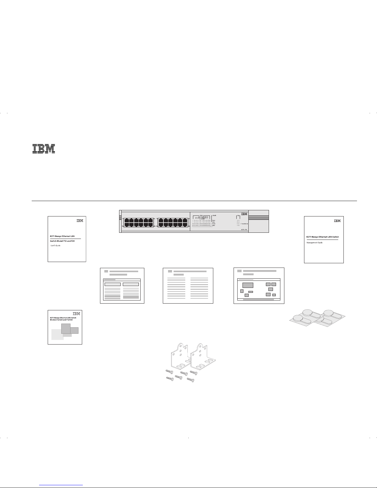
Package Contents
Quick Reference Guide
Version 2.0
User’s Guide
Quick Installation Guide
CD-ROM
8271 Model F12 (02L0878)
8271 Model F24 (02L0879)
Release Notes
4 x rubber feet
6 x mounting brackets and 6 x fixing screws
Management Guide
Page 2
Installing the Switch
DANGER: SD21-0030.
The User’s Guide also contains further information
on the following steps.
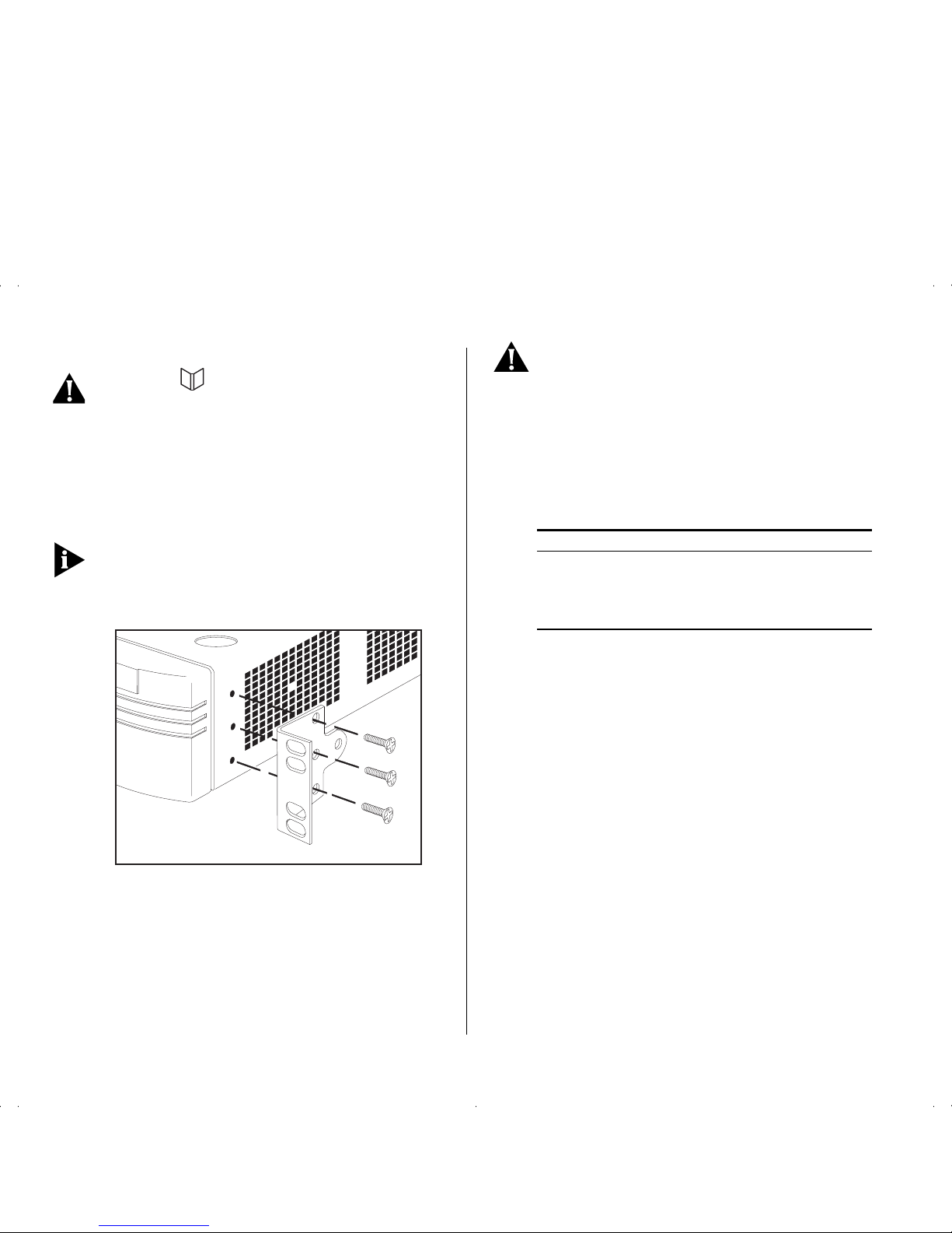
Installing the Switch into a 19-inch Rack
Fit the brackets as shown in the figure below to
each side of the unit. Following the manufacturer’s
instructions, secure the unit into the rack.
You must use the screws supplied with the mounting
brackets. Damage caused to the unit by using incorrect
screws will invalidate your warranty.
Powering-up the Switch
1
Plug the power cord into the power socket at the rear of
the Switch.
2
Plug the other end of the power cord into your power
outlet.
DANGER:
It is essential that the mains socket
outlet is installed near to the unit and is accessible. You can only disconnect the unit by removing
the appliance coupler from the unit.
The Switch powers-up and runs through its Power
On Self Test (POST), which takes approximately 12
seconds. When the POST is complete, check the
Power/Self Test LED to see that your Switch is operating correctly
Setting Up for Management
For information about setting up the Switch for
management, see Chapter 3 of the User’s Guide.
Further Information
■
You can find further information about installing
and powering-up the Switch in the IBM 8271
Nways Ethernet LAN Switch Model F12 and F24
User’s Guide.
■
For information about setting up the Switch for
management, refer to Chapter 2 of the IBM Nways
Ethernet LAN Switch Management Guide.
Color State
Green The Switch is powered-up and operating
normally.
Yellow The Switch has failed its POST.
Off The Switch is not receiving power.
Part Number: 35L2189
Published: January, 1999
 Loading...