

Page 1

Power Systems
7316-TF4 18.5-Inch Flat Panel
Rack-Mounted Monitor and Keyboard
Page 2

Page 3

Power Systems
7316-TF4 18.5-Inch Flat Panel
Rack-Mounted Monitor and Keyboard
Page 4

Note
Before using this information and the product it supports, read the information in “Safety notices” on page v, “Notices” on
page 51, the IBM Systems Safety Notices manual, G229-9054, and the IBM Environmental Notices and User Guide, Z125–5823.
This edition applies to IBM Power Systems servers that contain the POWER8 processor and to all associated
models.
© Copyright IBM Corporation 2014, 2015.
US Government Users Restricted Rights – Use, duplication or disclosure restricted by GSA ADP Schedule Contract
with IBM Corp.
Page 5

Contents
Safety notices .................................v
Installing the 7316-TF4 18.5-Inch Flat Panel Rack-Mounted monitor and keyboard....1
What's new in Installing the 7316-TF4 18.5-Inch Flat Panel Rack-Mounted monitor and keyboard .......1
PDF file for Installing the 7316-TF4 17-Inch Flat Panel Rack-Mounted monitor and keyboard ........1
Installing the 7316-TF4 17-Inch Flat Panel Rack-Mounted Monitor and Keyboard ...........1
Overview of 7316-TF4 18.5-Inch Flat Panel Rack-Mounted Monitor and Keyboard ............2
Console features .................................2
Check Your Inventory ...............................2
The IBM Documentation CD .............................4
Hardware and software requirements .........................4
Using the documentation browser ..........................4
Notices and statements in this document .........................5
Console unit specifications..............................5
Rail-to-rail depth measurements ...........................5
Dimensions and weight..............................6
Installing the 7316-TF4 18.5-Inch Flat Panel Rack-Mounted Monitor and Keyboard ............6
Installing the keyboard in the console unit ........................8
Installing the console unit in the rack ..........................9
Installing the optional console switch..........................16
Using the TFT-LCD display ..............................18
Using the on-screen display (OSD) menu ........................18
Using the control buttons.............................18
Using the display menu .............................19
Maintaining the TFT-LCD display ...........................20
Technical specifications ..............................21
Supported resolution timing charts ..........................22
Hardware maintenance information ...........................27
Replaceable components ..............................27
Power cords ..................................28
Replacing the keyboard ..............................30
Replacing the cable-management arm .........................32
Replacing the slide-rail assemblies ...........................34
Replacing the console unit .............................40
Removing the console unit from the rack .......................40
Moving the keyboard ..............................42
Removing and replacing the outer slide-rails ......................43
Installing the console unit in the rack.........................46
Notices ...................................51
Privacy policy considerations .............................52
Trademarks ...................................53
Electronic emission notices ..............................53
Class A Notices .................................53
Class B Notices .................................57
Terms and conditions ................................60
© Copyright IBM Corp. 2014, 2015 iii
Page 6

iv Power Systems: 7316-TF4 18.5-Inch Flat Panel Rack-Mounted Monitor and Keyboard
Page 7

Safety notices
Safety notices may be printed throughout this guide:
v DANGER notices call attention to a situation that is potentially lethal or extremely hazardous to
people.
v CAUTION notices call attention to a situation that is potentially hazardous to people because of some
existing condition.
v Attention notices call attention to the possibility of damage to a program, device, system, or data.
World Trade safety information
Several countries require the safety information contained in product publications to be presented in their
national languages. If this requirement applies to your country, safety information documentation is
included in the publications package (such as in printed documentation, on DVD, or as part of the
product) shipped with the product. The documentation contains the safety information in your national
language with references to the U.S. English source. Before using a U.S. English publication to install,
operate, or service this product, you must first become familiar with the related safety information
documentation. You should also refer to the safety information documentation any time you do not
clearly understand any safety information in the U.S. English publications.
Replacement or additional copies of safety information documentation can be obtained by calling the IBM
Hotline at 1-800-300-8751.
German safety information
Das Produkt ist nicht für den Einsatz an Bildschirmarbeitsplätzen im Sinne§2der
Bildschirmarbeitsverordnung geeignet.
Laser safety information
IBM®servers can use I/O cards or features that are fiber-optic based and that utilize lasers or LEDs.
Laser compliance
IBM servers may be installed inside or outside of an IT equipment rack.
© Copyright IBM Corp. 2014, 2015 v
Page 8

DANGER
When working on or around the system, observe the following precautions:
Electrical voltage and current from power, telephone, and communication cables are hazardous. To
avoid a shock hazard:
v If IBM supplied the power cord(s), connect power to this unit only with the IBM provided power
cord. Do not use the IBM provided power cord for any other product.
v Do not open or service any power supply assembly.
v Do not connect or disconnect any cables or perform installation, maintenance, or reconfiguration
of this product during an electrical storm.
v The product might be equipped with multiple power cords. To remove all hazardous voltages,
disconnect all power cords.
v Connect all power cords to a properly wired and grounded electrical outlet. Ensure that the outlet
supplies proper voltage and phase rotation according to the system rating plate.
v Connect any equipment that will be attached to this product to properly wired outlets.
v When possible, use one hand only to connect or disconnect signal cables.
v Never turn on any equipment when there is evidence of fire, water, or structural damage.
v Do not attempt to switch on power to the machine until all possible unsafe conditions are
corrected.
v Assume that an electrical safety hazard is present. Perform all continuity, grounding, and power
checks specified during the subsystem installation procedures to ensure that the machine meets
safety requirements.
v Do not continue with the inspection if any unsafe conditions are present.
v Disconnect the attached power cords, telecommunications systems, networks, and modems before
you open the device covers, unless instructed otherwise in the installation and configuration
procedures.
v Connect and disconnect cables as described in the following procedures when installing, moving,
or opening covers on this product or attached devices.
To Disconnect:
1. Turn off everything (unless instructed otherwise).
2. Remove the power cords from the outlets.
3. Remove the signal cables from the connectors.
4. Remove all cables from the devices.
To Connect:
1. Turn off everything (unless instructed otherwise).
2. Attach all cables to the devices.
3. Attach the signal cables to the connectors.
4. Attach the power cords to the outlets.
5. Turn on the devices.
Sharp edges, corners and joints may be present in and around the system. Use care when
handling equipment to avoid cuts, scrapes and pinching.
(D005)
DANGER
vi Power Systems: 7316-TF4 18.5-Inch Flat Panel Rack-Mounted Monitor and Keyboard
Page 9
Observe the following precautions when working on or around your IT rack system:
v Heavy equipment–personal injury or equipment damage might result if mishandled.
v Always lower the leveling pads on the rack cabinet.
v Always install stabilizer brackets on the rack cabinet.
v To avoid hazardous conditions due to uneven mechanical loading, always install the heaviest
devices in the bottom of the rack cabinet. Always install servers and optional devices starting
from the bottom of the rack cabinet.
v Rack-mounted devices are not to be used as shelves or work spaces. Do not place objects on top
of rack-mounted devices.
v Each rack cabinet might have more than one power cord. Be sure to disconnect all power cords in
the rack cabinet when directed to disconnect power during servicing.
v Connect all devices installed in a rack cabinet to power devices installed in the same rack
cabinet. Do not plug a power cord from a device installed in one rack cabinet into a power
device installed in a different rack cabinet.
v An electrical outlet that is not correctly wired could place hazardous voltage on the metal parts of
the system or the devices that attach to the system. It is the responsibility of the customer to
ensure that the outlet is correctly wired and grounded to prevent an electrical shock.
CAUTION
v Do not install a unit in a rack where the internal rack ambient temperatures will exceed the
manufacturer's recommended ambient temperature for all your rack-mounted devices.
v Do not install a unit in a rack where the air flow is compromised. Ensure that air flow is not
blocked or reduced on any side, front, or back of a unit used for air flow through the unit.
v Consideration should be given to the connection of the equipment to the supply circuit so that
overloading of the circuits does not compromise the supply wiring or overcurrent protection. To
provide the correct power connection to a rack, refer to the rating labels located on the
equipment in the rack to determine the total power requirement of the supply circuit.
v (For sliding drawers.) Do not pull out or install any drawer or feature if the rack stabilizer brackets
are not attached to the rack. Do not pull out more than one drawer at a time. The rack might
become unstable if you pull out more than one drawer at a time.
v (For fixed drawers.) This drawer is a fixed drawer and must not be moved for servicing unless
specified by the manufacturer. Attempting to move the drawer partially or completely out of the
rack might cause the rack to become unstable or cause the drawer to fall out of the rack.
(R001)
Safety notices vii
Page 10

CAUTION:
Removing components from the upper positions in the rack cabinet improves rack stability during
relocation. Follow these general guidelines whenever you relocate a populated rack cabinet within a
room or building.
v Reduce the weight of the rack cabinet by removing equipment starting at the top of the rack
cabinet. When possible, restore the rack cabinet to the configuration of the rack cabinet as you
received it. If this configuration is not known, you must observe the following precautions:
– Remove all devices in the 32U position (compliance ID RACK-001 or 22U (compliance ID RR001)
and above.
– Ensure that the heaviest devices are installed in the bottom of the rack cabinet.
– Ensure that there are little-to-no empty U-levels between devices installed in the rack cabinet
below the 32U (compliance ID RACK-001 or 22U (compliance ID RR001) level, unless the
received configuration specifically allowed it.
v If the rack cabinet you are relocating is part of a suite of rack cabinets, detach the rack cabinet from
the suite.
v If the rack cabinet you are relocating was supplied with removable outriggers they must be
reinstalled before the cabinet is relocated.
v Inspect the route that you plan to take to eliminate potential hazards.
v Verify that the route that you choose can support the weight of the loaded rack cabinet. Refer to the
documentation that comes with your rack cabinet for the weight of a loaded rack cabinet.
v Verify that all door openings are at least 760 x 230 mm (30 x 80 in.).
v Ensure that all devices, shelves, drawers, doors, and cables are secure.
v Ensure that the four leveling pads are raised to their highest position.
v Ensure that there is no stabilizer bracket installed on the rack cabinet during movement.
v Do not use a ramp inclined at more than 10 degrees.
v When the rack cabinet is in the new location, complete the following steps:
– Lower the four leveling pads.
– Install stabilizer brackets on the rack cabinet.
– If you removed any devices from the rack cabinet, repopulate the rack cabinet from the lowest
position to the highest position.
v If a long-distance relocation is required, restore the rack cabinet to the configuration of the rack
cabinet as you received it. Pack the rack cabinet in the original packaging material, or equivalent.
Also lower the leveling pads to raise the casters off of the pallet and bolt the rack cabinet to the
pallet.
(R002)
(L001)
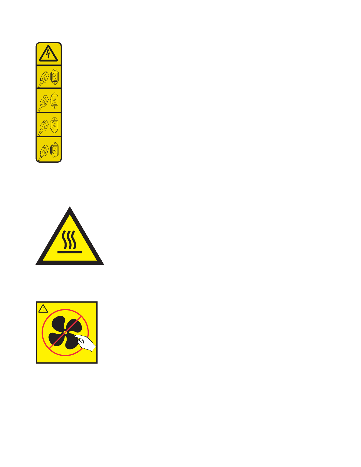
DANGER: Hazardous voltage, current, or energy levels are present inside any component that has this
label attached. Do not open any cover or barrier that contains this label. (L001)
(L002)
viii Power Systems: 7316-TF4 18.5-Inch Flat Panel Rack-Mounted Monitor and Keyboard
Page 11

DANGER: Rack-mounted devices are not to be used as shelves or work spaces. (L002)
(L003)
or
or
or
3
4
12
Safety notices ix
Page 12
1
2
3
4
DANGER: Multiple power cords. The product might be equipped with multiple power cords. To remove
all hazardous voltages, disconnect all power cords. (L003)
(L007)
CAUTION: A hot surface nearby. (L007)
(L008)
CAUTION: Hazardous moving parts nearby. (L008)
All lasers are certified in the U.S. to conform to the requirements of DHHS 21 CFR Subchapter J for class
1 laser products. Outside the U.S., they are certified to be in compliance with IEC 60825 as a class 1 laser
product. Consult the label on each part for laser certification numbers and approval information.
x Power Systems: 7316-TF4 18.5-Inch Flat Panel Rack-Mounted Monitor and Keyboard
Page 13

CAUTION:
This product might contain one or more of the following devices: CD-ROM drive, DVD-ROM drive,
DVD-RAM drive, or laser module, which are Class 1 laser products. Note the following information:
v Do not remove the covers. Removing the covers of the laser product could result in exposure to
hazardous laser radiation. There are no serviceable parts inside the device.
v Use of the controls or adjustments or performance of procedures other than those specified herein
might result in hazardous radiation exposure.
(C026)
CAUTION:
Data processing environments can contain equipment transmitting on system links with laser modules
that operate at greater than Class 1 power levels. For this reason, never look into the end of an optical
fiber cable or open receptacle. Although shining light into one end and looking into the other end of
a disconnected optical fiber to verify the continuity of optic fibers many not injure the eye, this
procedure is potentially dangerous. Therefore, verifying the continuity of optical fibers by shining
light into one end and looking at the other end is not recommended. To verify continuity of a fiber
optic cable, use an optical light source and power meter. (C027)
CAUTION:
This product contains a Class 1M laser. Do not view directly with optical instruments. (C028)
CAUTION:
Some laser products contain an embedded Class 3A or Class 3B laser diode. Note the following
information: laser radiation when open. Do not stare into the beam, do not view directly with optical
instruments, and avoid direct exposure to the beam. (C030)
CAUTION:
The battery contains lithium. To avoid possible explosion, do not burn or charge the battery.
Do Not:
v ___ Throw or immerse into water
v ___ Heat to more than 100°C (212°F)
v ___ Repair or disassemble
Exchange only with the IBM-approved part. Recycle or discard the battery as instructed by local
regulations. In the United States, IBM has a process for the collection of this battery. For information,
call 1-800-426-4333. Have the IBM part number for the battery unit available when you call. (C003)
(C048)
CAUTION regarding IBM provided VENDOR LIFT TOOL:
v Operation of LIFT TOOL by authorized personnel only.
v LIFT TOOL intended for use to assist, lift, install, remove units (load) up into rack elevations. It is
not to be used loaded transporting over major ramps nor as a replacement for such designated tools
like pallet jacks, walkies, fork trucks and such related relocation practices. When this is not
practicable, specially trained persons or services must be used (for instance, riggers or movers).
v Read and completely understand the contents of LIFT TOOL operator's manual before using.
Failure to read, understand, obey safety rules, and follow instructions may result in property
damage and/or personal injury. If there are questions, contact the vendor's service and support.
Local paper manual must remain with machine in provided storage sleeve area. Latest revision
manual available on vendor's web site.
v Test verify stabilizer brake function before each use. Do not over-force moving or rolling the LIFT
TOOL with stabilizer brake engaged.
v Do not move LIFT TOOL while platform is raised, except for minor positioning.
Safety notices xi
Page 14

v Do not exceed rated load capacity. See LOAD CAPACITY CHART regarding maximum loads at
center versus edge of extended platform.
v Only raise load if properly centered on platform. Do not place more than 200 lb (91 kg) on edge of
sliding platform shelf also considering the load's center of mass/gravity (CoG).
v Do not corner load the platform tilt riser accessory option. Secure platform riser tilt option to main
shelf in all four (4x) locations with provided hardware only, prior to use. Load objects are designed
to slide on/off smooth platforms without appreciable force, so take care not to push or lean. Keep
riser tilt option flat at all times except for final minor adjustment when needed.
v Do not stand under overhanging load.
v Do not use on uneven surface, incline or decline (major ramps).
v Do not stack loads.
v Do not operate while under the influence of drugs or alcohol.
v Do not support ladder against LIFT TOOL.
v Tipping hazard. Do not push or lean against load with raised platform.
v Do not use as a personnel lifting platform or step. No riders.
v Do not stand on any part of lift. Not a step.
v Do not climb on mast.
v Do not operate a damaged or malfunctioning LIFT TOOL machine.
v Crush and pinch point hazard below platform. Only lower load in areas clear of personnel and
obstructions. Keep hands and feet clear during operation.
v No Forks. Never lift or move bare LIFT TOOL MACHINE with pallet truck, jack or fork lift.
v Mast extends higher than platform. Be aware of ceiling height, cable trays, sprinklers, lights, and
other overhead objects.
v Do not leave LIFT TOOL machine unattended with an elevated load.
v Watch and keep hands, fingers, and clothing clear when equipment is in motion.
v Turn Winch with hand power only. If winch handle cannot be cranked easily with one hand, it is
probably over-loaded. Do not continue to turn winch past top or bottom of platform travel.
Excessive unwinding will detach handle and damage cable. Always hold handle when lowering,
unwinding. Always assure self that winch is holding load before releasing winch handle.
v A winch accident could cause serious injury. Not for moving humans. Make certain clicking sound
is heard as the equipment is being raised. Be sure winch is locked in position before releasing
handle. Read instruction page before operating this winch. Never allow winch to unwind freely.
Freewheeling will cause uneven cable wrapping around winch drum, damage cable, and may cause
serious injury. (C048)
Power and cabling information for NEBS (Network Equipment-Building System)
GR-1089-CORE
The following comments apply to the IBM servers that have been designated as conforming to NEBS
(Network Equipment-Building System) GR-1089-CORE:
The equipment is suitable for installation in the following:
v Network telecommunications facilities
v Locations where the NEC (National Electrical Code) applies
The intrabuilding ports of this equipment are suitable for connection to intrabuilding or unexposed
wiring or cabling only. The intrabuilding ports of this equipment must not be metallically connected to the
interfaces that connect to the OSP (outside plant) or its wiring. These interfaces are designed for use as
intrabuilding interfaces only (Type 2 or Type 4 ports as described in GR-1089-CORE) and require isolation
from the exposed OSP cabling. The addition of primary protectors is not sufficient protection to connect
these interfaces metallically to OSP wiring.
xii Power Systems: 7316-TF4 18.5-Inch Flat Panel Rack-Mounted Monitor and Keyboard
Page 15

Note: All Ethernet cables must be shielded and grounded at both ends.
The ac-powered system does not require the use of an external surge protection device (SPD).
The dc-powered system employs an isolated DC return (DC-I) design. The DC battery return terminal
shall not be connected to the chassis or frame ground.
The dc-powered system is intended to be installed in a common bonding network (CBN) as described in
GR-1089-CORE.
Safety notices xiii
Page 16

xiv Power Systems: 7316-TF4 18.5-Inch Flat Panel Rack-Mounted Monitor and Keyboard
Page 17

Installing the 7316-TF4 18.5-Inch Flat Panel Rack-Mounted monitor and keyboard
Learn how to install the 7316-TF4 18.5-Inch Flat Panel Rack-Mounted Monitor and Keyboard.
What's new in Installing the 7316-TF4 18.5-Inch Flat Panel Rack-Mounted monitor and keyboard
Read about new or significantly changed information in installing the 7316-TF4 18.5-Inch Flat Panel
Rack-Mounted Monitor and Keyboard since the previous update of this topic collection.
June 2015
v Added voltage specifications.
June 2014
v Added information for IBM Power Systems™servers that contain the POWER8®processor.
PDF file for Installing the 7316-TF4 17-Inch Flat Panel Rack-Mounted monitor and keyboard
You can view and print a PDF file of this information.
Installing the 7316-TF4 17-Inch Flat Panel Rack-Mounted Monitor and Keyboard
This document helps you to install the 7316-TF4 17-Inch Flat Panel Rack-Mounted Monitor and Keyboard
in the rack.
The latest version of this document is maintained online, see 7316-TF4 18.5-Inch Flat Panel Rack-Mounted
Monitor and Keyboard (http://www.ibm.com/support/knowledgecenter/POWER8/p8egg/
p8egg_840_kickoff.htm).
Saving PDF files
Large PDF files can be difficult to open online. For best results, save the PDF file to your local drive for
viewing or printing. Follow these steps:
1. Right-click the PDF link in your browser.
2. Click the option that saves the PDF locally.
3. Navigate to the directory in which you want to save the PDF file.
4. Click Save.
Downloading Adobe Reader
You need Adobe Reader installed on your system to view or print these PDF files. You can download a
free copy from the Adobe Reader website.
© Copyright IBM Corp. 2014, 2015 1
Page 18

Overview of 7316-TF4 18.5-Inch Flat Panel Rack-Mounted Monitor and Keyboard
This topic collection provides the overview of the 7316-TF4 18.5-Inch Flat Panel Rack-Mounted Monitor
and Keyboard.
The IBM 7316-TF4 18.5-Inch Flat Panel Rack-Mounted Monitor and Keyboard is a flat-panel display and
keyboard tray in one unit. The console unit occupies 1U
console switch behind the standard console in the rack to attach more than one server to the flat-panel
display and keyboard. If firmware and documentation updates are available, you can download them
from the IBM website.
Note: The 1 EIA unit in racks are measured in vertical increments of 1.75 inches each. Each 1.75-inch
increment is called an “EIA.” In some countries, the same increment may be referred to as a “U.”
1
of space in a rack. You can install an optional
Console features
Learn about the 7316-TF4 18.5-Inch Flat Panel Rack-Mounted Monitor and Keyboard console features.
The standard console has the following features:
v Mounts on slide-rails in the rack to enable easy movement and storage of the monitor
v Toolless rack installation in the 1U space of IBM rack configurations
v 18.5-inch, 16:9 ratio LCD panel with a VGA connection to the server or KVM switch
v Support for widescreen and previous (through scaling) resolutions
v Compatible with worldwide power and regulatory requirements
v Cable-management arm comes preinstalled on the rear of the console
v Can be shipped installed in an IBM rack
Check Your Inventory
Find information about the parts shipped along with the 7316-TF4 18.5-Inch Flat Panel Rack-Mounted
Monitor and Keyboard console.
Note: The illustrations in this topic might differ slightly from your hardware.
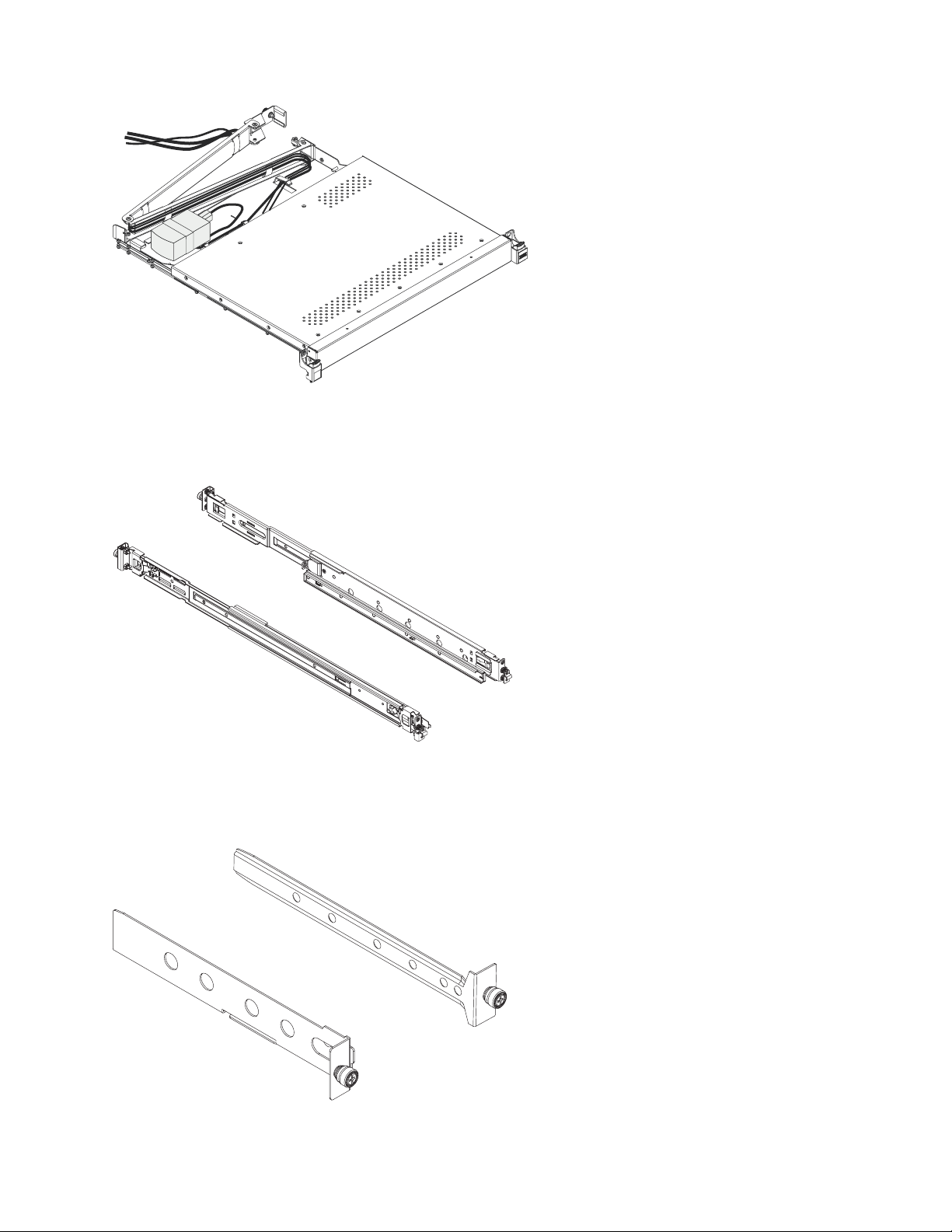
The console kit contains the following items:
v One console unit with built-in flat-panel display and cable-management arm (A 1 m power cord is
routed along the cable-management arm and is secured with cable straps.)
2 Power Systems: 7316-TF4 18.5-Inch Flat Panel Rack-Mounted Monitor and Keyboard
Page 19
P8EGB500-0
Important: The ac adapter that is connected to the flat-panel display is not intended for use with other
products. Do not disassemble the flat-panel display or remove the ac adapter.
v Two outer rails
P8EGB501-0
v Two console-switch mounting brackets, one with a channel (for routing the power, video, and
keyboard-and-mouse cables) and six screws.
P8EGB502-0
Installing the 7316-TF4 18.5-Inch Flat Panel Rack-Mounted monitor and keyboard 3
Page 20

v One 2.8-m (9-ft) IEC connector power cable
P8EGB503-0
v Bag with M5 clip nuts, M5 stability screws, and M5 shipping screws
v IBM Documentation CD
You need the following tools to replace customer replaceable units (CRU):
v One #1 Phillips screwdriver (to install or remove the inner slide-rails)
v One #2 Phillips screwdriver (to unscrew the shipping screws from the rack if you move the rack to
another location; to replace the cable-management arm)
See the documentation that comes with your rack or console switch for more information about those
products.
The IBM Documentation CD
Learn about the IBM Documentation CD shipped along with the 7316-TF4 18.5-Inch Flat Panel
Rack-Mounted Monitor and Keyboard console.
The IBM Documentation CD contains documentation for the console unit in Portable Document Format
(PDF) and includes the IBM Documentation Browser to help you find information quickly.
Hardware and software requirements
Learn about the hardware and software requirements to run the IBM Documentation CD.
The IBM Documentation CD requires the following minimum hardware and software:
v Microsoft Windows XP, Windows 2000, or Red Hat Linux
v 100 MHz microprocessor
v 32 MB of RAM
v Adobe Acrobat Reader 3.0 (or later) or xpdf, which comes with Linux operating systems
Using the documentation browser
Learn about how to use the documentation browser.
Use the Documentation Browser to browse the contents of the CD, read brief descriptions of the
documents, and view documents, using Adobe Acrobat Reader or xpdf. The Documentation Browser
automatically detects the regional settings in use in your server and displays the documents in the
language for that region (if available). If a document is not available in the language for that region, the
English-language version is displayed.
Use one of the following procedures to start the Documentation Browser:
v If Autostart is enabled, insert the CD into the CD or DVD drive. The Documentation Browser starts
automatically.
v If Autostart is disabled or is not enabled for all users, use one of the following procedures:
– If you are using a Windows operating system, insert the CD into the CD or DVD drive and click
Start --> Run. In the Open field, type e:\win32.bat.
where e is the drive letter of the CD or DVD drive, and click OK.
– If you are using Red Hat Linux, insert the CD into the CD or DVD drive; then, run the following
command from the /mnt/cdrom directory: sh runlinux.sh
4 Power Systems: 7316-TF4 18.5-Inch Flat Panel Rack-Mounted Monitor and Keyboard
Page 21

Select the console unit from the Product menu. The Available Topics list displays all the documents for
the console unit. Some documents might be in folders. A plus sign (+) indicates each folder or document
that has additional documents under it. Click the plus sign to display the additional documents.
When you select a document, a description of the document is displayed under Topic Description.To
select more than one document, press and hold the Ctrl key while you select the documents. Click View
Book to view the selected document or documents in Acrobat Reader or xpdf. If you selected more than
one document, all the selected documents are opened in Acrobat Reader or xpdf.
To search all the documents, type a word or word string in the Search field and click Search. The
documents in which the word or word string appears are listed in order of the most occurrences. Click a
document to view it, and press Crtl+F to use the Acrobat search function, or press Alt+F to use the xpdf
search function within the document. Click Help for detailed information about using the Documentation
Browser.
Notices and statements in this document
This topic provides the information on the notices and statements used in this document.
The caution and danger statements in this document are also in the multilingual Safety Information
document. Each statement is numbered for reference to the corresponding statement in the Safety
Information document.
The following notices and statements are used in this document:
Note: These notices provide important tips, guidance, or advice.
Important: These notices provide information or advice that might help you avoid inconvenient or
problem situations.
Attention: These notices indicate potential damage to programs, devices, or data. An attention notice is
placed just before the instruction or situation in which damage might occur.
CAUTION:
These statements indicate situations that can be potentially hazardous to you. A caution statement is
placed just before the description of a potentially hazardous procedure step or situation.
DANGER
These statements indicate situations that can be potentially lethal or extremely hazardous to you. A
danger statement is placed just before the description of a potentially lethal or extremely hazardous
procedure step or situation.
Console unit specifications
This topic collection provides the information about the specifications of the console unit.
The following sections provide the console unit specifications.
Rail-to-rail depth measurements
This topic provides the information about the rail-to-rail depth measurement to install the 7316-TF4
18.5-Inch Flat Panel Rack-Mounted Monitor and Keyboard.
The console unit fits in a rack with the front to rear rail dimensions as shown in the following table. The
console unit dimensions are measured outside-to-outside and are for IBM and non-IBM racks with
unthreaded and threaded holes.
Installing the 7316-TF4 18.5-Inch Flat Panel Rack-Mounted monitor and keyboard 5
Page 22
Table 1. Console unit rack post distances
Rack configuration Rack post distances
No console switch 613 - 909 mm (24.1 - 35.8 in.]
Provision for a console switch 706 - 909 mm (27.9 - 35.8 in.]
Dimensions and weight
This topic provides the information about the dimensions and weight of the console unit.
The following table describes the console unit dimensions and weight.
Table 2. Console unit dimensions and weight
Height 44 mm (1.75 in.) (display in stored position)
Width 434 mm (17 in.) (main chassis only, slide-rails not
included, faceplate not included)
Depth 434 mm (17 in.) (chassis behind EIA mounting flange,
bezel in front of EIA flange not included,
cable-management arm not included)
Bezel depth 35 mm (1.4 in.) (including latches and IBM Logo)
Bezel width 482 mm (19 in.) (includes latches)
Maximum forward extension 650 mm (25.6 in.)
Weight 10.4 kg (23 lb)
Installing the 7316-TF4 18.5-Inch Flat Panel Rack-Mounted Monitor and Keyboard
This topic collection provides the information to install the 7316-TF4 18.5-Inch Flat Panel Rack-Mounted
Monitor and Keyboard console.
The console unit occupies 1U of mounting space in a rack. To install the console unit in the rack,
complete the steps in the following sections. Removing the rack doors and side panels, and removing the
rack devices that are above and below where you want to install the console unit, might make installation
easier.
See the documentation that comes with your rack for additional information.
Guidelines for rack mounting the console unit:
v Elevated operating ambient - If installed in a closed or multi-unit rack assembly, the operating ambient
temperature of the rack environment might be greater than room ambient. Therefore, consideration
should be given to installing the equipment in an environment compatible with the maximum ambient
temperature (Tma) specified by the manufacturer.
v Reduced air flow - Installation of the equipment in a rack should be such that the amount of air flow
required for safe operation of the equipment is not compromised.
v Mechanical loading - Mounting of the equipment in the rack should be such that a hazardous
condition is not achieved due to uneven mechanical loading.
v Circuit overloading - Consideration should be given to the connection of the equipment to the supply
circuit and the effect that overloading of the circuits might have on overcurrent protection and supply
wiring. Appropriate consideration of equipment nameplate ratings should be used when addressing
this concern.
6 Power Systems: 7316-TF4 18.5-Inch Flat Panel Rack-Mounted Monitor and Keyboard
Page 23

v Reliable earthing - Reliable earthing of rack-mounted equipment should be maintained. Particular
attention should be given to supply connections other than direct connections to the branch circuit (for
example, use of power strips).
DANGER
When working on or around the system, observe the following precautions:
Electrical voltage and current from power, telephone, and communication cables are hazardous. To
avoid a shock hazard:
v If IBM supplied the power cord(s), connect power to this unit only with the IBM provided power
cord. Do not use the IBM provided power cord for any other product.
v Do not open or service any power supply assembly.
v Do not connect or disconnect any cables or perform installation, maintenance, or reconfiguration
of this product during an electrical storm.
v The product might be equipped with multiple power cords. To remove all hazardous voltages,
disconnect all power cords.
v Connect all power cords to a properly wired and grounded electrical outlet. Ensure that the outlet
supplies proper voltage and phase rotation according to the system rating plate.
v Connect any equipment that will be attached to this product to properly wired outlets.
v When possible, use one hand only to connect or disconnect signal cables.
v Never turn on any equipment when there is evidence of fire, water, or structural damage.
v Do not attempt to switch on power to the machine until all possible unsafe conditions are
corrected.
v Assume that an electrical safety hazard is present. Perform all continuity, grounding, and power
checks specified during the subsystem installation procedures to ensure that the machine meets
safety requirements.
v Do not continue with the inspection if any unsafe conditions are present.
v Disconnect the attached power cords, telecommunications systems, networks, and modems before
you open the device covers, unless instructed otherwise in the installation and configuration
procedures.
v Connect and disconnect cables as described in the following procedures when installing, moving,
or opening covers on this product or attached devices.
To Disconnect:
1. Turn off everything (unless instructed otherwise).
2. Remove the power cords from the outlets.
3. Remove the signal cables from the connectors.
4. Remove all cables from the devices.
To Connect:
1. Turn off everything (unless instructed otherwise).
2. Attach all cables to the devices.
3. Attach the signal cables to the connectors.
4. Attach the power cords to the outlets.
5. Turn on the devices.
Sharp edges, corners and joints may be present in and around the system. Use care when
handling equipment to avoid cuts, scrapes and pinching.
(D005)
CAUTION:
This product is equipped with a 3-wire (two conductors and ground) power cable and plug. Use this
power cable with a properly grounded electrical outlet to avoid electrical shock. C018
Installing the 7316-TF4 18.5-Inch Flat Panel Rack-Mounted monitor and keyboard 7
Page 24
Installing the keyboard in the console unit
Learn how to install the keyboard in the console unit.
To install the keyboard in the console unit, complete the following steps:
1. Place the console unit on a table or other flat surface and make sure that the right side of the unit
extends approximately 76 mm (3 in.) over the edge of the surface. This will help you route the
keyboard-and-mouse cable more easily later in the procedure.
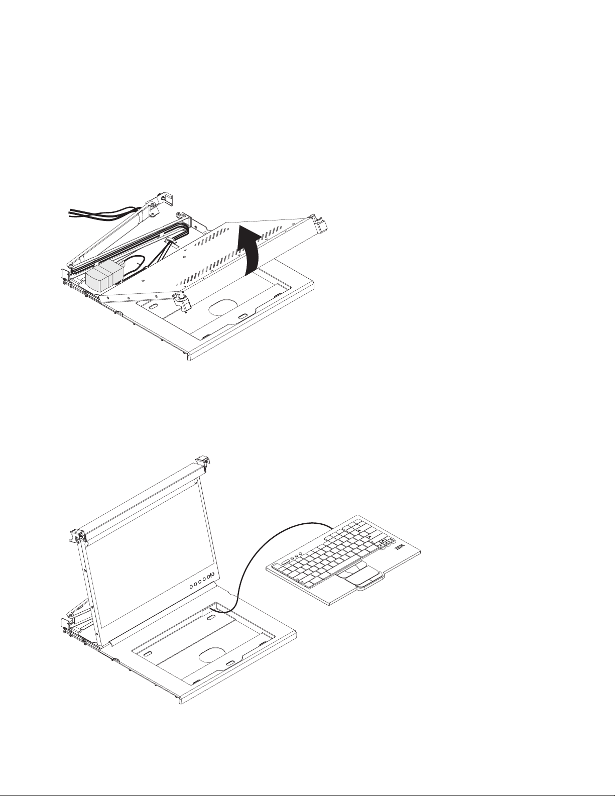
2. Carefully lift the front of the flat-panel display to the full upright position.
P8EGB504-0
Attention: Do not extend the keyboard feet. The flat-panel display screen might be damaged if the
feet are extended when the display is closed.
3. Hold the keyboard near the keyboard tray and carefully route the keyboard-and-mouse cable down
through the keyboard tray cutout and up through the cutout that is behind the flat-panel display. (See
the illustration.) Carefully pull the cable through the cutouts.
p
U
g
n
e
P
D
m
g
e
o
P
c
H
a
d
e
p
n
rt
s
s
te
E
k
c
a
In
le
e
B
e
s
|
u
D
a
k
P
rL
c
S
1
c
1
F
rtS
P
0
9F1
F
9
8
F
I
8
7
F
U
7
6
F
5
F
4
F
4
3
F
3
c
s
E
E
2
F
2
W
1
F
1
Q
c
~
A
o
`
k
L
b
s
a
T
p
a
C
ift
h
S
nC
F
J
Y
6
H
T
5
G
R
B
F
V
D
C
S
X
Z
lt
A
t
rl
\
2
1
F
_
0
O
K
M
N
r
+
=
}
te
n
]
E
-
{
ift
[
h
“
S
P
‘
:
;
?
/
L
>
t
rl
.
C
<
,
lt
A
P8EGB505-0
4. Peel the backing of the double-sided foam tape that is preinstalled on the front of the console tray.
8 Power Systems: 7316-TF4 18.5-Inch Flat Panel Rack-Mounted Monitor and Keyboard
Page 25

5. Place the keyboard in the tray and exert a small amount of pressure on the keyboard to secure it to
the double-sided tape.
6. Close the flat-panel display.
Attention:
v When you route the keyboard-and-mouse cable, make sure that the cable does not hang below the
underside of the keyboard where it might be damaged if it interferes with the devices in the rack
space below the console unit.
v Make sure that you route all cables through the cable-routing features on the console frame behind
the display and along the cable-management arm.
7. Route the cable along the cable-management arm, securing the cables with the hook-and-loop fastener
strips.
Installing the console unit in the rack
Learn how to install the console unit in the rack.
Review the documentation that comes with your rack for safety and cabling information. When you
install your system in a rack, observe the following guidelines:
v Make sure that the room air temperature is below 35°C (95°F).
v Do not block any air vents; usually 15 cm (6 in.) of air space provides proper airflow.
v Plan the device installation starting from the bottom of the rack.
v Install the heaviest device in the bottom of the rack.
v Do not extend more than one device out of the rack at the same time.
v Connect all power cords to properly wired and grounded electrical outlets.
v Do not overload the power outlet when you install multiple devices in the rack.
v You can install the outer slide-rails in a square-hole rack, round-hole rack, or threaded-hole rack and
no tools are required.
To install the console unit in the rack, complete the following steps:
1. Place the console unit on a stable, flat surface.
Attention: The video cable is connected to the flat-panel display. As you install the console unit in
the rack, be careful that you do not pinch or cut the video cable.
2. Select a 1U location in the rack for the console unit.
3. Remove the shipping screw from each outer slide-rail.
Installing the 7316-TF4 18.5-Inch Flat Panel Rack-Mounted monitor and keyboard 9
Page 26

Slide-rail rear
Shipping screw
Slide-rail front
Shipping screw
P8EGB506-0
4. (For non-threaded hole racks) Install an M5 clip nut in the front of the rack in the top hole of the 1
U-space position that you select. The clip nuts are in the bag of screws that come with the console
unit.
M5 clip nut
M5 clip nut
P8EGB507-0
5. To attach the outer slide-rail to the rack, complete the following steps.
Note: Install the rear slide-rail bracket on the rear of the rack first; then, install the front slide-rail
bracket on the front of the rack.
a. Holding the slide-rail horizontally, align the rear slide-rail bracket so that the bracket is on the
outside of the rack mounting flanges.
b. Press the rear slide-rail bracket towards the rack flange and then pull it towards the front of the
rack until the locking bracket clicks into place behind the rack flange.
10 Power Systems: 7316-TF4 18.5-Inch Flat Panel Rack-Mounted Monitor and Keyboard
Page 27

Slide-rail rear
P8EGB508-0
c. Extend the slide-rail and press the front slide-rail bracket towards the rack flange and then push
it towards the rear of the rack until the locking bracket clicks into place behind the rack flange.
Slide-rail front
P8EGB509-0
d. Repeat steps 5a to 5c to attach the other outer slide-rail.
Note: Make sure that the two pins in the slide-rail brackets are pressed completely into the rack
holes and that the bracket is flush with the rack flange. You might have to move the slide-rail up
and down several times, and press on the end of the bracket to release the pins so that they are
correctly in the holes in the rack flange.
Installing the 7316-TF4 18.5-Inch Flat Panel Rack-Mounted monitor and keyboard 11
Page 28

P8EGB510-0
6. Remove the rollers from the rail and fasten them to the display using three screws on each rail.
Rear
Front
P8EGB530-0
Carefully slide the console unit into the ball-bearing assemblies in the rails. Carefully slide the rollers
on the console unit into the notch in the slide-rails as shown in the illustration.
12 Power Systems: 7316-TF4 18.5-Inch Flat Panel Rack-Mounted Monitor and Keyboard
Page 29

P8EGB511-0
7. Press in both release latches 1; then, grasp both sides of the console unit and push it completely into
the rack 2. There will be resistance initially as the inner and outer rails are aligned. Pull the console
unit out halfway, and then push it back in to seat the console unit in the rails. Do this a few times
until the console unit moves smoothly in the rails.
Release latch
1
2
1
Release latch
8. On the right rail, align the C-channel on the end of the cable-management arm with the bracket on
the console unit. Slide the C-channel onto the bracket until the cable-management arm thumbscrew
aligns with the hole in the bracket. Tighten the thumbscrew.
2
Installing the 7316-TF4 18.5-Inch Flat Panel Rack-Mounted monitor and keyboard 13
P8EGB512-0
Page 30

Thumbscrew
Cable-management arm
P8EGB513-0
9. Connect all cables to either a server or a console switch in the rack. Connect the power cord to the
short jumper cord on the cable-management arm, and then connect the power cord to a properly
grounded electrical outlet or power distribution unit (PDU). For information about installing a
console switch behind the console unit in the rack, see Installing the Optional Console Switch.
10. Fully extend the console unit from the front of the rack, and then neatly route the cables within the
rack and secure them with cable straps along the way.
Important: If you have excess video cable, do not coil it as shown in the following illustration.
14 Power Systems: 7316-TF4 18.5-Inch Flat Panel Rack-Mounted Monitor and Keyboard
Page 31

P8EGB514-0
To minimize the electrical interference if you have excess video cable, arrange the cable in
figure-eight loops, as shown in the following illustration. Secure the cable in the middle with a cable
tie or strap.
Cable tie
P8EGB515-0
(Optional for all racks) To secure the slide-rails to the rack after installation, install an M5 flat-head
stabilizer screw in the top hole on the front of each slide-rail.
Installing the 7316-TF4 18.5-Inch Flat Panel Rack-Mounted monitor and keyboard 15
Page 32

Stabilizer
screw
Stabilizer
screw
P8EGB516-0
Before you move a rack with a console unit to another location, secure the front of the console unit
to the rack with two M5 shipping screws that come in the bag of screws (see the illustration).
Shipping
screw
Shipping
screw
P8EGB517-0
11. See Using the TFT-LCD display for information about operating the display. See the keyboard
documentation for information about operating the keyboard.
Installing the optional console switch
Learn how to install the optional console switch.
You can use a console switch to attach more than one server to a single display and keyboard. The
optional console switch is available separately.
16 Power Systems: 7316-TF4 18.5-Inch Flat Panel Rack-Mounted Monitor and Keyboard
Page 33

Depending on the depth of the console switch and the depth of the rack, you might be able to mount a
console switch behind the console unit in the same 1U space. To mount the console switch behind the
console unit, use the custom mounting brackets that come with the console unit.
Important: The console switch extends beyond the rear rack-cabinet mounting flanges when you install
the switch behind the console unit.
Note:
v In this procedure, left and right refer to orientations as you are facing the rear of the rack.
v The console switch mounting brackets are supplied in the miscellaneous hardware kit.
v The mounting brackets have several pre-drilled holes and can support most console switch designs.
To install a console switch behind the tray, complete the following steps:
1. Attach the left-side bracket to the left side of the console switch using two 8-32 screws. Then, attach
the right-side bracket to the right side of the console switch.
Note: The left-side bracket has a channel for you to route the power, video, and keyboard-and-mouse
cables. Make sure that you attach the brackets to the console switch so that the channel on the
left-side bracket faces upward.
2. Install the console switch behind the flat-panel monitor and keyboard tray using four (two on each
side) of the Phillips screws supplied in your miscellaneous hardware kit.
Console
switch
screw
A
8
7
6
5
4
3
2
1
Console
switch screw
P8EGB519-0
3. Route the power, video, and keyboard-and-mouse cables through the channel in the left-side bracket
on the console switch. Then, connect the video, keyboard, and mouse connectors to the console
switch.
4. For information about connecting the flat-panel monitor, thin keyboard, and servers to the console
switch, see the documentation provided with the console switch.
Installing the 7316-TF4 18.5-Inch Flat Panel Rack-Mounted monitor and keyboard 17
Page 34

Using the TFT-LCD display
This topic collection provides the information about using the TFT-LCD display.
This chapter contains information about using the TFT-LCD display. For most applications, the factory
default settings on the display do not require adjustment.
Using the on-screen display (OSD) menu
Learn how to use the OSD menu to adjust the characteristics of the image that is being displayed.
Using the control buttons
Learn how to use the control buttons on the TFT - LCD display.
The control buttons on the lower right of the LCD display are shown in the following illustration.
P8EGB520-0
v Brightness/Contrast: Press this button to access the controls.
v Left arrow and right arrow buttons:
– Press the right arrow button to select the function that is to be adjusted.
– Press the left arrow or right arrow button to decrease or increase the value of the selected
adjustment or to select the correct setting.
v Exit button: Press this button to exit the menu or return 1 level in the menu.
v Select/Menu button: Press this button to access, select, or confirm a menu option.
18 Power Systems: 7316-TF4 18.5-Inch Flat Panel Rack-Mounted Monitor and Keyboard
Page 35

v Power button: Press this button to turn on and turn off the display power. This indicator shows the
status of the display operation:
– Green: Normal operation
– Flashing green: Standby power
– Black: Power is off
Using the display menu
Learn how to use the display menu on the TFT - LCD display.
To activate the display menu, press the Select/Menu button. The Main menu is displayed.
P8EGB521-0
The menu choices are described in the following list:
v Brightness/Contrast
– Brightness - Brightness Slider Default 50, incremental adjustment by 0 from1-100
– Contrast - Contrast Slider Default 50, incremental adjustment by 0 from1-100
v Display Settings
– Wide Mode
- 1:1 - Uses exact pixel count from video controller
- Aspect - Uses pixel ratio but scales to largest available picture
- Fill - Default. Scales incoming image to utilize full screen
– Horizontal Position - Screen picture adjustment - Default at 50 Center of the Screen, incremental
adjustment by 1 pixel from0-100
– Vertical Position - Screen picture adjustment - Default at 50 Center of the Screen, incremental
adjustment by 1 pixel from0-100
– Sharpness - Visual reference to light and dark - Default 50, incremental adjustment by 10 from 0 -
100
– Pixel Clock - Analog input control - Default Panel Dependent
– Phase - Analog input control - Default Panel Dependent
– Display Info - Display Resolution and Refresh Rate
– Reset Display settings - Reset Display Settings to Factory Default - confirmation required
v Color Settings
– Standard
– Warm
Installing the 7316-TF4 18.5-Inch Flat Panel Rack-Mounted monitor and keyboard 19
Page 36

– Cool
– Custom Color - If selected, the following RGB default values are displayed:
- Red - Default 50, incremental adjustment by 1, from0-100
- Blue - Default 50, incremental adjustment by 1, from0-100
- Green - Default 50, incremental adjustment by 1, from0-100
– Reset Color Settings - Resets color to factory default - confirmation required
v Auto Adjust - Auto adjustment - confirmation required
v Other Settings
– Language
- English - Converts OSD UI into local language chosen by user (default language)
- Spanish - Converts OSD UI into local language chosen by user
- French - Converts OSD UI into local language chosen by user
- German - Converts OSD UI into local language chosen by user
- Japanese - Converts OSD UI into local language chosen by user
- Korean - Converts OSD UI into local language chosen by user
- Simple Chinese - Converts OSD UI into local language chosen by user
– Menu Timer Sliding scale by 5 second increments, from 5 to 100 - default is 20
– DDC/CI On/Off - default is On
– LCD Conditioning On/Off - default is Off
– Reset Reset Other settings to Factory Default - confirmation required
v Factory Reset - Reset all settings to default
Maintaining the TFT-LCD display
Learn how to maintain the TFT-LCD display.
Statement 8:
P8EGB522-0
CAUTION: Never remove the cover on a power supply or any part that has the following label attached.
P8EGB523-0
Hazardous voltage, current, and energy levels are present inside any component that has this label
attached. There are no serviceable parts inside these components. If you suspect a problem with one of
these parts, contact a service technician.
Before you perform any maintenance on the display, turn off the power. Observe the following guidelines
when you clean the display:
v Gently wipe the device covers and the screen with a soft cloth.
20 Power Systems: 7316-TF4 18.5-Inch Flat Panel Rack-Mounted Monitor and Keyboard
Page 37

v Remove finger marks and grease with a damp cloth and mild detergent; do not use solvents or
abrasives.
v Never use flammable cleaning material to clean an IBM display or any other electronic device.
Technical specifications
This topic provides the detailed technical specifications of the TFT-LCD display unit.
The technical specifications for the console unit are described in the following list.
LCD Panel
Size 18.5-inch diagonal
Display area (horizontal x vertical) 376.32 x 301.056 mm
Type TFT active matrix
Pixel pitch (horizontal x vertical) 0.294 x 0.294 mm
Characteristics
Brightness 250 cd /m2 (Typ.)
Contrast ratio 1000:1 (Typ.)
Display color 16.7 M colors
Viewing Angle Horizontal - 170°
Vertical - 160°
Aspect Ratio 16:9 (Native)
Scaling 1:1, Aspect and Fill
Display resolution
Optimum mode 1280 x 1024 at 60 Hz
Maximum mode 1280 x 1024 at 70 Hz
Note: For the supported display resolutions, see, Supported resolution timing charts.
Connector VGA
Power Supply ac 100 - 240 V, 60 - 50 Hz
dc 12 V/ 5.0 A
Power Consumption
Standard usage 17 watts
Maximum 22 watts
Power supply maximum 40 Watts
Power Saving Less than 1 Watts
Environmental conditions
Operating temperature 0°C to 50°C
Operating humidity 10% to 80%
Operating altitude maximum 3000 meters
Storage temperature -20°C to +60°C
Installing the 7316-TF4 18.5-Inch Flat Panel Rack-Mounted monitor and keyboard 21
Page 38

Storage humidity 5% to 95%
Storage altitude maximum 3000 meters
Supported resolution timing charts
This topic provides the detailed supported resolution timing charts for the TFT-LCD display unit.
The following tables are the supported resolution timing charts. Although additional resolutions might
work, these are the supported signals.
Table 3. 640 x 480 timing chart
Type Standard
Timing name 640 x 480 @ 60 Hz 640 x 480 @ 75 Hz
Horizontal frequency
and polarity
Vertical frequency
and polarity
Pixel clock 25.175 MHz 31.5 MHz
Scan type Noninterlaced Noninterlaced
Horizontal
Period 31.778 µs 800 pixels 26.667 µs 840 pixels
Display 25.422 µs 640 pixels 20.317 µs 640 pixels
Blanking 6.356 µs 160 pixels 6.349 µs 200 pixels
Sync 3.813 µs 96 pixels 2.032 µs 64 pixels
Back porch 1.907 µs 48 pixels 3.810 µs 120 pixels
Front porch 0.636 µs 16 pixels 0.508 µs 16 pixels
Vertical
Total 16.683 ms 525 lines 13.333 ms 500 lines
Display 15.253 ms 480 lines 12.800 ms 480 lines
Blanking 1.430 ms 45 lines 0.533 ms 20 lines
Sync 0.064 ms 2 lines 0.080 ms 3 lines
Back porch 1.049 ms 33 lines 0.427 ms 16 lines
Front porch 0.318 ms 10 lines 0.027 ms 1 line
31.469 kHz Negative 37.5 kHz Negative
59.94 Hz Negative 75 Hz Negative
Table 4. 800 x 600 timing chart
Type Standard
Timing name 800 x 600 @ 60 Hz 800 x 600 @ 75 Hz
Horizontal frequency
and polarity
Vertical frequency
and polarity
Pixel clock 40 MHz 49.5 MHz
Scan type Noninterlaced Noninterlaced
Horizontal
Period 26.400 µs 1056 pixels 21.333 µs 1056 pixels
37.879 kHz Positive 46.875 kHz Positive
60.317 Hz Positive 75 Hz Positive
22 Power Systems: 7316-TF4 18.5-Inch Flat Panel Rack-Mounted Monitor and Keyboard
Page 39

Table 4. 800 x 600 timing chart (continued)
Type Standard
Display 20.000 µs 800 pixels 16.162 µs 800 pixels
Blanking 6.400 µs 256 pixels 5.172 µs 256 pixels
Sync 3.200 µs 128 pixels 1.616 µs 80 pixels
Back porch 2.200 µs 88 pixels 3.232 µs 160 pixels
Front porch 1.000 µs 40 pixels 0.323 µs 16 pixels
Vertical
Total 16.579 ms 628 lines 13.333 ms 625 lines
Display 15.840 ms 600 lines 12.800 ms 600 lines
Blanking 0.739 ms 28 lines 0.533 ms 25 lines
Sync 0.106 ms 4 lines 0.064 ms 3 lines
Back porch 0.607 ms 23 lines 0.448 ms 21 lines
Front porch 0.026 ms 1 line 0.021 ms 1 line
Table 5. 1024 x 768 timing chart
Type Standard
Timing name 800 x 600 @ 60 Hz 800 x 600 @ 75 Hz
Horizontal frequency
48.363 kHz Negative 60.023 kHz Negative
and polarity
Vertical frequency
60.004 Hz Negative 75.029 Hz Negative
and polarity
Pixel clock 65 MHz 78.75 MHz
Scan type Noninterlaced Noninterlaced
Horizontal
Period 20.677 µs 1344 pixels 16.660 µs 1312 pixels
Display 15.754 µs 1024 pixels 13.003 µs 1024 pixels
Blanking 4.923 µs 320 pixels 3.657 µs 288 pixels
Sync 2.092 µs 136 pixels 1.219 µs 96 pixels
Back porch 2.462 µs 160 pixels 2.235 µs 176 pixels
Front porch 0.369 µs 24 pixels 0.203 µs 16 pixels
Vertical
Total 16.666 ms 806 lines 13.328 ms 800 lines
Display 15.880 ms 768 lines 12.795 ms 768 lines
Blanking 0.786 ms 38 lines 0.533 ms 32 lines
Sync 0.124 ms 6 lines 0.050 ms 3 lines
Back porch 0.600 ms 29 lines 0.466 ms 28 lines
Front porch 0.062 ms 3 lines 0.017 ms 1 line
Table 6. 1152 x 864 timing chart
Type Standard
Timing name 1152 x 864 @ 60 Hz 1152 x 864 @ 75 Hz
Installing the 7316-TF4 18.5-Inch Flat Panel Rack-Mounted monitor and keyboard 23
Page 40

Table 6. 1152 x 864 timing chart (continued)
Type Standard
Horizontal frequency
and polarity
Vertical frequency
and polarity
Pixel clock 80 MHz 108 MHz
Scan type Noninterlaced Noninterlaced
Horizontal
Period 18.400 µs 1472 pixels 14.815 µs 1600 pixels
Display 14.400 µs 1152 pixels 10.667 µs 1152 pixels
Blanking 4.000 µs 320 pixels 4.148 µs 448 pixels
Sync 1.200 µs 96 pixels 1.185 µs 128 pixels
Back porch 2.400 µs 192 pixels 2.370 µs 256 pixels
Front porch 0.400 µs 32 pixels 0.593 µs 64 pixels
Vertical
Total 16.652 ms 905 lines 13.333 ms 900 lines
Display 15.898 ms 864 lines 12.800 ms 864 lines
Blanking 0.754 ms 41 lines 0.533 ms 36 lines
Sync 0.055 ms 3 lines 0.044 ms 3 lines
Back porch 0.681 ms 37 lines 0.474 ms 32 lines
Front porch 0.018 ms 1 line 0.015 ms 1 line
54.348 kHz Positive 67.5 kHz Positive
60.053 Hz Positive 75 Hz Positive
Table 7. 1366 x 768 timing chart
Type Standard
Timing name 1366 x 768 @ 60 Hz 1366 x 768 @ 75 Hz
Horizontal frequency
and polarity
Vertical frequency
and polarity
Pixel clock 85.5 MHz 110.195 MHz
Scan type Noninterlaced Noninterlaced
Horizontal
Period 20.959 µs 1792 pixels 16.625 µs 1832 pixels
Display 15.976 µs 1366 pixels 12.396 µs 1366 pixels
Blanking 4.983 µs 426 pixels 4.231 µs 466 pixels
Sync 1.310 µs 112 pixels 1.307 µs 144 pixels
Back porch 2.929 µs 250 pixels 2.120 µs 234 pixels
Front porch 0.749 µs 64 pixels 0.799 µs 88 pixels
Vertical
Total 16.662 ms 795 lines 13.333 ms 802 lines
Display 16.097 ms 768 lines 12.768 ms 768 lines
Blanking 0.566 ms 27 lines 0.565 ms 34 lines
47.712 kHz Positive 60.15 kHz Positive
60.053 Hz Positive 75 Hz Positive
24 Power Systems: 7316-TF4 18.5-Inch Flat Panel Rack-Mounted Monitor and Keyboard
Page 41

Table 7. 1366 x 768 timing chart (continued)
Type Standard
Sync 0.126 ms 6 lines 0.049 ms 3 lines
Back porch 0.377 ms 18 lines 0.498 ms 30 lines
Front porch 0.063 ms 3 lines 0.015 ms 1 line
Table 8. 1280 x 800 timing chart
Type Standard
Timing name 1280 x 800 @ 60 Hz 1280 x 800 @ 75 Hz
Horizontal frequency
49.702 kHz Negative 62.795 kHz Negative
and polarity
Vertical frequency
59.81 Hz Positive 74.934 Hz Positive
and polarity
Pixel clock 83.5 MHz 106.5 MHz
Scan type Noninterlaced Noninterlaced
Horizontal
Period 20.120 µs 1680 pixels 15.925 µs 1696 pixels
Display 15.329 µs 1280 pixels 12.019 µs 1280 pixels
Blanking 4.790 µs 400 pixels 3.906 µs 416 pixels
Sync 1.533 µs 128 pixels 1.202 µs 128 pixels
Back porch 2.395 µs 200 pixels 1.935 µs 206 pixels
Front porch 0.862 µs 72 pixels 0.751 µs 80 pixels
Vertical
Total 16.720 ms 831 lines 13.345 ms 838 lines
Display 16.096 ms 800 lines 12.740 ms 800 lines
Blanking 0.624 ms 31 lines 0.605 ms 38 lines
Sync 0.121 ms 6 lines 0.096 ms 6 lines
Back porch 0.443 ms 22 lines 0.462 ms 29 lines
Front porch 0.060 ms 3 lines 0.048 ms 3 lines
Table 9. 1280 x 1024 timing chart
Type Standard
Timing name 1280 x 1024 @ 60 Hz 1280 x 1024 @ 75 Hz
Horizontal frequency
63.981 kHz Positive 79.976 kHz Positive
and polarity
Vertical frequency
60.02 Hz Positive 75.025 Hz Positive
and polarity
Pixel clock 108 MHz 135 MHz
Scan type Noninterlaced Noninterlaced
Horizontal
Period 15.630 µs 1688 pixels 12.504 µs 1688 pixels
Display 11.852 µs 1280 pixels 9.481 µs 1280 pixels
Blanking 3.778 µs 408 pixels 3.022 µs 408 pixels
Installing the 7316-TF4 18.5-Inch Flat Panel Rack-Mounted monitor and keyboard 25
Page 42

Table 9. 1280 x 1024 timing chart (continued)
Type Standard
Sync 1.037 µs 112 pixels 1.067 µs 144 pixels
Back porch 2.296 µs 248 pixels 1.837 µs 248 pixels
Front porch 0.444 µs 48 pixels 0.119 µs 16 pixels
Vertical
Total 16.661 ms 1066 lines 13.329 ms 1066 lines
Display 16.005 ms 1024 lines 12.804 ms 1024 lines
Blanking 0.656 ms 42 lines 0.525 ms 42 lines
Sync 0.047 ms 3 lines 0.038 ms 3 lines
Back porch 0.594 ms 38 lines 0.475 ms 38 lines
Front porch 0.016 ms 1 line 0.013 ms 1 line
Table 10. 1440 x 900 timing chart
Type Standard
Timing name 1440 x 900 @ 60 Hz 1440 x 900 @ 75 Hz
Horizontal frequency
and polarity
Vertical frequency
and polarity
Pixel clock 106.5 MHz 136.75 MHz
Scan type Noninterlaced Noninterlaced
Horizontal
Period 17.878 µs 1904 pixels 14.157 µs 1936 pixels
Display 13.521 µs 1440 pixels 10.530 µs 1440 pixels
Blanking 4.357 µs 464 pixels 3.627 µs 496 pixels
Sync 1.427 µs 152 pixels 1.112 µs 152 pixels
Back porch 2.178 µs 232 pixels 1.814 µs 248 pixels
Front porch 0.751 µs 80 pixels 0.702 µs 96 pixels
Vertical
Total 16.698 ms 934 lines 13.336 ms 942 lines
Display 16.090 ms 900 lines 12.741 ms 900 lines
Blanking 0.608 ms 34 lines 0.595 ms 42 lines
Sync 0.107 ms 6 lines 0.085 ms 6 lines
Back porch 0.447 ms 25 lines 0.467 ms 33 lines
Front porch 0.054 ms 3 lines 0.042 ms 3 lines
55.935 kHz Negative 70.635 kHz Negative
59.887 Hz Positive 74.984 Hz Positive
Table 11. 1600 x 1200 timing chart
Type Standard
Timing name 1600 x 1200 @ 60 Hz 1600 x 1200 @ 75 Hz
Horizontal frequency
and polarity
75 kHz Positive 65.29 kHz Negative
26 Power Systems: 7316-TF4 18.5-Inch Flat Panel Rack-Mounted Monitor and Keyboard
Page 43

Table 11. 1600 x 1200 timing chart (continued)
Type Standard
Vertical frequency
and polarity
Pixel clock 162 MHz 146.25 MHz
Scan type Noninterlaced Noninterlaced
Horizontal
Period 13.333 µs 2160 pixels 15.316 µs 2240 pixels
Display 9.877 µs 1600 pixels 11.487 µs 1680 pixels
Blanking 3.457 µs 560 pixels 3.829 µs 560 pixels
Sync 1.185 µs 192 pixels 1.203 µs 176 pixels
Back porch 1.877 µs 304 pixels 1.915 µs 280 pixels
Front porch 0.395 µs 64 pixels 0.711 µs 104 pixels
Vertical
Total 16.667 ms 1250 lines 16.679 ms 1084 lines
Display 16.000 ms 1200 lines 16.082 ms 1050 lines
Blanking 0.667 ms 50 lines 0.597 ms 39 lines
Sync 0.040 ms 3 lines 0.092 ms 6 lines
Back porch 0.613 ms 46 lines 0.459 ms 30 lines
Front porch 0.013 ms 1 line 0.046 ms 3 lines
60 Hz Positive 59.954 Hz Positive
Hardware maintenance information
This topic collection provides the information about the IBM Customer-replaceable units (CRUs) for the
console unit and instructions for the replacement parts.
Replaceable components
This topic provides the information about the replaceable components of the 7316-TF4 18.5-Inch Flat
Panel Rack-Mounted Monitor and Keyboard console.
Field replaceable units (FRUs) must be replaced only by a trained service technician, unless they are
classified as customer replaceable units (CRUs).
Tier 1 CRU: Replacement of Tier 1 CRUs is your responsibility. If IBM installs a Tier 1 CRU at your
request without a service contract, you will be charged for the installation.
Tier 2 CRU: You may install a Tier 2 CRU yourself or request IBM to install it, at no additional charge,
under the type of warranty service that is designated for your product.
For more information about the terms of the warranty and getting service and assistance, see the
Warranty Information document that comes with the optional device.
IBM CRU part numbers are subject to change without notice. This section contains a listing of the CRU
part numbers that are available as of the date of this document was written.
Installing the 7316-TF4 18.5-Inch Flat Panel Rack-Mounted monitor and keyboard 27
Page 44

1U standard console
Right rail
Left rail
P8EGB524-0
Table 12. Field replaceable units for the IBM 1U 18.5-inch Standard Console
Description CRU part number (Tier 1)
IBM 1U 18.5-inch Standard Console, without keyboard 47C2521
Standard slide-rail kit (inner and outer rails) 44X3116
Cable-management arm 44X3114
Miscellaneous parts kit (includes shipping screws,
console switch mounting brackets and mounting screws)
Power cord that connects the power supply to a power
distribution unit (PDU)
44X3120
39M5377
You need the following tools to replace customer replaceable units:
v One #1 Phillips screwdriver (to install or remove the inner slide-rails)
v One #2 Phillips screwdriver (to replace the cable-management arm)
Power cords
This topic provides the information about the power cords and the part number of the power cords for
different countries across the world.
For your safety, IBM provides a power cord with a grounded attachment plug to use with this IBM
product. To avoid electrical shock, always use the power cord and plug with a properly grounded outlet.
IBM power cords used in the United States and Canada are listed by Underwriter's Laboratories (UL) and
certified by the Canadian Standards Association (CSA).
28 Power Systems: 7316-TF4 18.5-Inch Flat Panel Rack-Mounted Monitor and Keyboard
Page 45

For units intended to be operated at 115 volts: Use a UL-listed and CSA-certified cord set consisting of a
minimum 18 AWG, Type SVT or SJT, three-conductor cord, a maximum of 15 feet in length and a parallel
blade, grounding-type attachment plug rated 15 amperes, 125 volts.
For units intended to be operated at 230 volts (U.S. use): Use a UL-listed and CSA-certified cord set
consisting of a minimum 18 AWG, Type SVT or SJT, three-conductor cord, a maximum of 15 feet in
length and a tandem blade, grounding-type attachment plug rated 15 amperes, 250 volts.
For units intended to be operated at 230 volts (outside the U.S.): Use a cord set with a grounding-type
attachment plug. The cord set should have the appropriate safety approvals for the country in which the
equipment will be installed.
IBM power cords for a specific country or region are usually available only in that country or region.
Table 13. Power cord part numbers and associated regions
IBM power cord part number Used in these countries and regions
39M5206 China
39M5102 Australia, Fiji, Kiribati, Nauru, New Zealand, Papua
New Guinea
39M5123 Afghanistan, Albania, Algeria, Andorra, Angola,
Armenia, Austria, Azerbaijan, Belarus, Belgium, Benin,
Bosnia and Herzegovina, Bulgaria, Burkina Faso,
Burundi, Cambodia, Cameroon, Cape Verde, Central
African Republic, Chad, Comoros, Congo (Democratic
Republic of), Congo (Republic of), Cote D’Ivoire (Ivory
Coast), Croatia (Republic of), Czech Republic, Dahomey,
Djibouti, Egypt, Equatorial Guinea, Eritrea, Estonia,
Ethiopia, Finland, France, French Guyana, French
Polynesia, Germany, Greece, Guadeloupe, Guinea,
Guinea Bissau, Hungary, Iceland, Indonesia, Iran,
Kazakhstan, Kyrgyzstan, Laos (People’s Democratic
Republic of), Latvia, Lebanon, Lithuania, Luxembourg,
Macedonia (former Yugoslav Republic of), Madagascar,
Mali, Martinique, Mauritania, Mauritius, Mayotte,
Moldova (Republic of), Monaco, Mongolia, Morocco,
Mozambique, Netherlands, New Caledonia, Niger,
Norway, Poland, Portugal, Reunion, Romania, Russian
Federation, Rwanda, Sao Tome and Principe, Saudi
Arabia, Senegal, Serbia, Slovakia, Slovenia (Republic of),
Somalia, Spain, Suriname, Sweden, Syrian Arab Republic,
Tajikistan, Tahiti, Togo, Tunisia, Turkey, Turkmenistan,
Ukraine, Upper Volta, Uzbekistan, Vanuatu, Vietnam,
Wallis and Futuna, Yugoslavia (Federal Republic of),
Zaire
39M5130 Denmark
39M5144 Bangladesh, Lesotho, Macao, Maldives, Namibia, Nepal,
Pakistan, Samoa, South Africa, Sri Lanka, Swaziland,
Uganda
Installing the 7316-TF4 18.5-Inch Flat Panel Rack-Mounted monitor and keyboard 29
Page 46

Table 13. Power cord part numbers and associated regions (continued)
IBM power cord part number Used in these countries and regions
39M5151 Abu Dhabi, Bahrain, Botswana, Brunei Darussalam,
Channel Islands, China (Hong Kong S.A.R.), Cyprus,
Dominica, Gambia, Ghana, Grenada, Iraq, Ireland,
Jordan, Kenya, Kuwait, Liberia, Malawi, Malaysia, Malta,
Myanmar (Burma), Nigeria, Oman, Polynesia, Qatar,
Saint Kitts and Nevis, Saint Lucia, Saint Vincent and the
Grenadines, Seychelles, Sierra Leone, Singapore, Sudan,
Tanzania (United Republic of), Trinidad and Tobago,
United Arab Emirates (Dubai), United Kingdom, Yemen,
Zambia, Zimbabwe
39M5158 Liechtenstein, Switzerland
39M5165 Chile, Italy, Libyan Arab Jamahiriya
39M5172 Israel
39M5095 220 - 240 V Antigua and Barbuda, Aruba, Bahamas,
Barbados, Belize, Bermuda, Bolivia, Brazil, Caicos
Islands, Canada, Cayman Islands, Colombia, Costa Rica,
Cuba, Dominican Republic, Ecuador, El Salvador, Guam,
Guatemala, Haiti, Honduras, Jamaica, Japan, Mexico,
Micronesia (Federal States of), Netherlands Antilles,
Nicaragua, Panama, Peru, Philippines, Taiwan, United
States of America, Venezuela
39M5081 110 - 120 V Antigua and Barbuda, Aruba, Bahamas,
Barbados, Belize, Bermuda, Bolivia, Caicos Islands,
Canada, Cayman Islands, Colombia, Costa Rica, Cuba,
Dominican Republic, Ecuador, El Salvador, Guam,
Guatemala, Haiti, Honduras, Jamaica, Mexico, Micronesia
(Federal States of), Netherlands Antilles, Nicaragua,
Panama, Peru, Philippines, Saudi Arabia, Thailand,
Taiwan, United States of America, Venezuela
39M5219 Korea (Democratic People’s Republic of), Korea (Republic
of)
39M5199 Japan
39M5068 Argentina, Paraguay, Uruguay
39M5226 India
39M5233 Brazil
Replacing the keyboard
Learn how to replace the keyboard from the console unit.
Before you replace the keyboard, remove any devices that are directly above the console unit so that you
have access to disconnect the cables. See the documentation that comes with the device for removal
instructions.
You can also remove the console unit from the rack for easier cable access. See the instructions in
Removing the console unit from the rack; then, return to step 5 in this procedure.
To replace a keyboard in the console unit, complete the following steps:
1. Close the flat-panel display.
2. Disconnect the keyboard-and-mouse cable from the server or console switch.
30 Power Systems: 7316-TF4 18.5-Inch Flat Panel Rack-Mounted Monitor and Keyboard
Page 47

3. Carefully unfasten the hook-and-loop fastener strips from the cable-management arm and remove
the keyboard-and-mouse cable.
L012
P8EGB525-0
CAUTION: Pinch hazard. (L012)
4. Fully extend the console unit out of the rack.
5. Lift the front of the flat-panel display and raise the display to the full upright position.
P8EGB504-0
6. Remove the old keyboard from the console unit.
7. Unpack the replacement keyboard.
Note: Do not extend the keyboard feet. The flat-panel display screen might be damaged if the feet is
extended when the display is closed.
8. Hold the new keyboard near the keyboard tray and carefully route the keyboard-and-mouse cable
down through the keyboard tray cutout and up through the cutout that is behind the flat-panel
display. (See the illustration.) Carefully pull the cable through the cutouts.
Installing the 7316-TF4 18.5-Inch Flat Panel Rack-Mounted monitor and keyboard 31
Page 48

p
U
g
n
e
P
D
m
g
e
o
P
c
H
a
d
e
p
n
rt
s
s
te
E
k
c
a
In
le
e
B
e
s
|
u
D
a
k
P
rL
c
S
1
c
1
F
rtS
P
0
9F1
F
9
8
F
I
8
7
F
U
7
6
F
5
F
4
4
3F
F
3
c
s
E
E
2
F
2
W
1
F
1
Q
c
~
A
o
`
k
L
b
s
a
T
p
a
t
C
if
h
S
nC
F
J
Y
6
H
T
5
G
R
B
F
V
D
C
S
X
Z
lt
A
t
rl
\
2
1
F
_
0
O
K
M
N
r
+
=
}
te
n
]
E
-
{
ift
[
h
“
S
P
‘
:
;
?
/
L
>
t
rl
.
C
<
,
lt
A
P8EGB505-0
9. Place the keyboard in the tray and exert a small amount of pressure on the keyboard to secure it to
the double-sided tape on the front of the console tray.
10. Close the flat-panel display.
11. If you removed the console unit from the rack, go to “Installing the console unit in the rack” to
complete the procedure.
Note: When you route the keyboard-and-mouse cable, make sure that the cable does not hang below
the underside of the keyboard where it might be damaged if it interferes with the devices in the rack
space below the console unit.
12. Route the keyboard-and-mouse cable along the cable-management arm, securing the cable with the
hook-and-loop fastener strips.
13. Reconnect the keyboard-and-mouse cable.
Replacing the cable-management arm
Learn how to replace the cable-management arm from the console unit.
Before you replace the cable-management arm, remove any devices that are directly above and below the
console unit so that you can disconnect the cables and detach the cable-management arm. See the
documentation that comes with the device for removal instructions.
You can also remove the console unit from the rack for easier access. See the instructions in Removing the
console unit from the rack; then, return to step 5 in this procedure.
To replace the cable-management arm, complete the following steps:
1. If a console switch is installed behind the console unit, remove the console switch from the rack.
2. Turn off the display and disconnect the power cord from the short jumper cord on the
cable-management arm from the electrical outlet or power distribution unit (PDU). Disconnect from
the server or console switch any cables that are connected to the console unit (keyboard-and-mouse,
video, and power cables).
3. Close the flat-panel display.
4. Temporarily remove all cables from the cable-management arm.
32 Power Systems: 7316-TF4 18.5-Inch Flat Panel Rack-Mounted Monitor and Keyboard
Page 49

5. Remove the screw that attaches the front cable-management arm bracket to the console unit and
then, remove the cable-management arm.
Screw
Cable-management arm
Washers
P8EGB526-0
6. Unpack the replacement cable-management arm.
7. Remove the two washers on the cable-management arm bracket and replace them with the new
washers that come with the replacement cable-management arm.
8. Align the screw holes in the new cable-management arm with the bracket and secure it with the
screw that you removed in step 5.
9. If you removed the console unit from the rack, go to Installing the console unit in the rack to
complete the procedure.
10. Route the cables that you removed in step 2 along the new cable-management arm and secure them
along the way with the hook-and-loop fastener strips.
11. Align the C-channel on the end of the cable-management arm with the bracket on the console unit.
Slide the C-channel onto the bracket until the cable-management arm thumbscrew aligns with the
hole in the bracket. Tighten the thumbscrew.
Installing the 7316-TF4 18.5-Inch Flat Panel Rack-Mounted monitor and keyboard 33
Page 50

Thumbscrew
Cable-management arm
P8EGB513-0
12. If you removed a console switch from behind the console unit, reinstall it now.
13. Reconnect to the server or console switch all cables that you removed in step 2.
14. Connect power to the display.
Replacing the slide-rail assemblies
Learn how to replace the slide-rail assemblies.
Note: To make sure that the slide-rail assemblies fit correctly, replace both the outer and inner slide-rails
at the same time.
To replace the outer and inner slide-rails for the console unit, complete the following steps:
1. If a console switch is installed behind the console unit, remove the console switch from the rack.
2. Turn off the display and disconnect the power cord from the short jumper cord on the
cable-management arm from the electrical outlet or power distribution unit (PDU). Disconnect from
the server or console switch any cables that are connected to the console unit (keyboard-and-mouse,
video, and power cables).
3. Close the flat-panel display.
4. If you installed the optional flat-head stabilizer screws in the top hole on the front of each slide-rail,
remove them and set them aside.
34 Power Systems: 7316-TF4 18.5-Inch Flat Panel Rack-Mounted Monitor and Keyboard
Page 51

Stabilizer
screw
Stabilizer
screw
P8EGB516-0
5. Remove the console unit from the rack:
a. Remove the thumbscrew that attaches the cable-management arm to the outer slide-rail bracket.
Slide the C-channel on the cable-management arm completely away from the bracket on the
console unit.
Thumbscrew
Cable-management arm
P8EGB513-0
Installing the 7316-TF4 18.5-Inch Flat Panel Rack-Mounted monitor and keyboard 35
Page 52

L012
P8EGB525-0
CAUTION: Pinch hazard. (L012)
b. Fully extend the console unit out of the rack.
c. Press in both release latches 1.
Release latch
1
2
1
Release latch
d. Grasp both sides of the console unit and pull it completely out of the rack 2.
e. Place the console unit on a table or other flat surface.
6. To close the extended rails, press up on the release latch 1 and push the extended rail towards the
rack so that it is fully closed 2.
2
P8EGB512-0
36 Power Systems: 7316-TF4 18.5-Inch Flat Panel Rack-Mounted Monitor and Keyboard
Page 53

2
1
P8EGB527-0
7. Remove the rear bracket of the outer slide-rail from the rack by pulling the blue tab out 1 while you
move the end of the slide-rail away from the rack flange and toward the center of the rack 2.
2
1
P8EGB528-0
8. Remove the front bracket of the outer slide-rail from the rack by pulling the blue tab out 1 while you
pull the end of the slide-rail away from the rack flange and toward the center of the rack 2.
Installing the 7316-TF4 18.5-Inch Flat Panel Rack-Mounted monitor and keyboard 37
Page 54

1
2
P8EGB529-0
Repeat step 7 and step 8 for the other outer slide-rail.
9. Remove the shipping screw from each new outer slide-rail.
Slide-rail rear
Shipping screw
Slide-rail front
Shipping screw
P8EGB506-0
10. To attach the outer slide-rail to the rack, complete the following steps.
Note: Install the rear slide-rail bracket to the rear of the rack first; then, install the front slide-rail
bracket to the front of the rack.
a. Holding the slide-rail horizontally, align the rear slide-rail bracket so that the bracket is on the
outside of the rack mounting flanges.
38 Power Systems: 7316-TF4 18.5-Inch Flat Panel Rack-Mounted Monitor and Keyboard
Page 55

b. Press the rear slide-rail bracket toward the rack flange and then pull it towards the front of the
rack until the locking bracket clicks into place behind the rack flange.
Slide-rail rear
P8EGB508-0
c. Extend the slide-rail and press the front slide-rail bracket toward the rack flange and then push it
towards the rear of the rack until the locking bracket clicks into place behind the rack flange.
Slide-rail front
P8EGB509-0
d. Repeat steps 10a to 10c to attach the other outer slide-rail.
11. Use a #1 Phillips screwdriver to remove the four screws that attach each inner slide-rail to the
console unit. Then, attach the corresponding new inner slide-rails to the unit, using the same
hardware. Make sure that you orient the inner slide rails correctly (see the illustration).
Installing the 7316-TF4 18.5-Inch Flat Panel Rack-Mounted monitor and keyboard 39
Page 56

Rear
Front
P8EGB530-0
12. Go to Installing the console unit in the rack for instructions for reinstalling the console unit in the
rack, and then install any other devices that you removed from the rack.
Replacing the console unit
This topic collection provides the information on how to replace the console unit.
The procedures that are provided in this section to replace the console unit in the rack consist of the
following tasks:
1. Removing the existing console unit from the rack
2. Moving the keyboard from the existing console unit to the replacement console unit
3. Removing and replacing the outer slide-rails
Note: The replacement console unit comes with inner slide-rails attached. To make sure that the
slide-rail assemblies fit correctly, replace the existing outer slide-rails with the new rails that come
with the replacement console unit.
4. Installing the replacement console unit in the rack.
Removing the rack doors and side panels might make removal of the existing console unit and
installation of the replacement easier. See the documentation that comes with the rack for additional
information.
Removing the console unit from the rack
Learn how to remove the console unit from the rack.
To remove the console unit from the rack, complete the following steps:
1. If a console switch is installed behind the console unit, remove the console switch from the rack.
2. Turn off the display and disconnect the power cord from the short jumper cord on the
cable-management arm from the electrical outlet or power distribution unit (PDU). Disconnect from
the server or console switch any cables that are connected to the console unit (keyboard-and-mouse,
video, and power cables).
3. Close the flat-panel display.
4. Remove the console unit from the rack:
a. Remove the thumbscrew that attaches the cable-management arm to the outer slide-rail bracket.
Slide the C-channel on the cable-management arm completely away from the bracket on the
40 Power Systems: 7316-TF4 18.5-Inch Flat Panel Rack-Mounted Monitor and Keyboard
Page 57

console unit.
Thumbscrew
Cable-management arm
L012
P8EGB525-0
CAUTION: Pinch hazard. (L012)
b. Fully extend the console unit out of the rack.
c. Press in both release latches 1.
P8EGB513-0
Installing the 7316-TF4 18.5-Inch Flat Panel Rack-Mounted monitor and keyboard 41
Page 58

Release latch
1
2
1
Release latch
d. Grasp both sides of the console unit and pull it completely out of the rack 2.
e. Place the console unit on a table or other flat surface.
2
P8EGB512-0
Moving the keyboard
Learn how to move the keyboard from the console unit.
To move the keyboard from the existing console unit to the replacement console unit, complete the
following steps:
1. Carefully lift the flat-panel display to the full upright position.
2. Remove the keyboard-and-mouse cable from the keyboard tray, and then remove the keyboard from
the console unit and set it aside.
3. Place the replacement console unit on a table or other flat surface and make sure that the right side of
the unit extends approximately 76 mm (3 in.) over the edge of the surface. This will help you route
the keyboard-and-mouse cable more easily.
4. Hold the keyboard near the keyboard tray and carefully route the keyboard-and-mouse cable down
through the keyboard tray cutout and up through the cutout that is behind the flat-panel display. (See
the illustration.) Carefully pull the cable through the cutouts.
42 Power Systems: 7316-TF4 18.5-Inch Flat Panel Rack-Mounted Monitor and Keyboard
Page 59

p
U
g
n
e
P
D
m
g
e
o
P
c
H
a
d
e
p
n
rt
s
s
te
E
k
c
a
In
le
e
B
e
s
|
u
D
a
k
P
rL
c
S
1
c
1
F
rtS
P
0
9F1
F
9
8
F
I
8
7
F
U
7
6
F
5
F
4
4
3F
F
3
E
c
2
s
F
E
2
W
1
F
1
Q
c
~
A
o
`
k
L
b
s
a
T
p
a
t
C
if
h
S
nC
F
J
Y
6
H
T
5
G
R
B
F
V
D
C
S
X
Z
lt
A
t
rl
\
2
1
F
_
0
O
K
M
N
r
+
=
}
te
n
]
E
-
{
ift
[
h
“
S
P
‘
:
;
?
/
L
>
t
rl
.
C
<
,
lt
A
P8EGB505-0
5. Place the keyboard in the tray and exert a small amount of pressure on the keyboard to secure it to
the double-sided tape on the front of the console tray.
6. Close the flat-panel display.
Attention:
v When you route the keyboard-and-mouse cable, make sure that the cable does not hang below the
underside of the keyboard where it might be damaged if it interferes with the devices in the rack
space below the console unit.
v Make sure that you route all cables through the cable-routing features on the console frame behind
the display and along the cable-management arm.
7. Close the flat-panel display.
Removing and replacing the outer slide-rails
Learn how to remove and replace the outer slide-rails.
To remove and replace the outer slide-rails, complete the following steps:
1. Remove the rear bracket of the outer slide-rail from the rack by pulling the blue tab out 1 while you
move the end of the slide-rail away from the rack flange and toward the center of the rack 2.
Installing the 7316-TF4 18.5-Inch Flat Panel Rack-Mounted monitor and keyboard 43
Page 60

2
1
P8EGB528-0
2. Remove the front bracket of the outer slide-rail from the rack by pulling the blue tab out 1 while you
pull the end of the slide-rail away from the rack flange and toward the center of the rack 2. Repeat
step 1 and step 2 for the other outer slide-rail.
44 Power Systems: 7316-TF4 18.5-Inch Flat Panel Rack-Mounted Monitor and Keyboard
Page 61

1
2
P8EGB529-0
3. Remove the shipping screw from each new outer slide-rail.
Slide-rail rear
Shipping screw
Slide-rail front
Shipping screw
P8EGB506-0
4. To attach the outer slide-rail to the rack, complete the following steps.
Note: Install the rear slide-rail bracket to the rear of the rack first; then, install the front slide-rail
bracket to the front of the rack.
a. Holding the slide-rail horizontally, align the rear slide-rail bracket so that the bracket is on the
outside of the rack mounting flanges.
Installing the 7316-TF4 18.5-Inch Flat Panel Rack-Mounted monitor and keyboard 45
Page 62

b. Press the rear slide-rail bracket towards the rack flange and then pull it towards the front of the
rack until the locking bracket clicks into place behind the rack flange.
Slide-rail rear
P8EGB508-0
c. Extend the slide-rail and press the front slide-rail bracket towards the rack flange and then push it
towards the rear of the rack until the locking bracket clicks into place behind the rack flange.
Slide-rail front
P8EGB509-0
d. Repeat steps 4a to 4c to attach the other outer slide-rail.
Installing the console unit in the rack
Learn how to install the console unit in the rack.
To install the console unit in the rack, complete the following steps:
1. Extend the inner part of the outer slide-rails and slide them forward to the front of the outer rails.
Carefully slide the rollers on the console unit into the notch in the slide-rails as shown in the
illustration.
46 Power Systems: 7316-TF4 18.5-Inch Flat Panel Rack-Mounted Monitor and Keyboard
Page 63

P8EGB511-0
2. Press in both release latches 1; then, grasp both sides of the console unit and push it completely into
the rack 2. There will be resistance initially as the inner and outer rails are aligned. Pull the console
unit out halfway, and then push it back in to seat the console unit in the rails. Do this a few times
until the console unit moves smoothly in the rails.
Release latch
1
2
1
Release latch
3. Align the C-channel on the end of the cable-management arm with the bracket on the console unit.
Slide the C-channel onto the bracket until the cable-management arm thumbscrew aligns with the
hole in the bracket. Tighten the thumbscrew.
2
Installing the 7316-TF4 18.5-Inch Flat Panel Rack-Mounted monitor and keyboard 47
P8EGB512-0
Page 64

Thumbscrew
Cable-management arm
4. Reinstall the stabilizer screws if you have removed them.
Stabilizer
screw
P8EGB513-0
Stabilizer
screw
P8EGB516-0
5. If you removed a console switch from behind the console unit, reinstall it now.
6. Reconnect to the server or console switch all cables that you removed.
48 Power Systems: 7316-TF4 18.5-Inch Flat Panel Rack-Mounted Monitor and Keyboard
Page 65

7. Connect power to the display.
8. Fully extend the console unit from the front of the rack, and then neatly route the cables within the
rack and secure them with cable straps along the way.
Important: If you have excess video cable, do not coil it as shown in the following illustration.
P8EGB514-0
To minimize the electrical interference if you have excess video cable, arrange the cable in figure-eight
loops, as shown in the following illustration. Secure the cable in the middle with a cable tie or strap.
Cable tie
P8EGB515-0
Installing the 7316-TF4 18.5-Inch Flat Panel Rack-Mounted monitor and keyboard 49
Page 66

50 Power Systems: 7316-TF4 18.5-Inch Flat Panel Rack-Mounted Monitor and Keyboard
Page 67

Notices
This information was developed for products and services that are offered in the USA. This material may
be available from IBM in other languages. However, you may be required to own a copy of the product
or product version in that language in order to access it.
IBM may not offer the products, services, or features discussed in this document in other countries.
Consult your local IBM representative for information on the products and services currently available in
your area. Any reference to an IBM product, program, or service is not intended to state or imply that
only that IBM product, program, or service may be used. Any functionally equivalent product, program,
or service that does not infringe any IBM intellectual property right may be used instead. However, it is
the user's responsibility to evaluate and verify the operation of any non-IBM product, program, or
service.
IBM may have patents or pending patent applications covering subject matter described in this
document. The furnishing of this document does not grant you any license to these patents. You can send
license inquiries, in writing, to:
IBM Director of Licensing
IBM Corporation
North Castle Drive, MD-NC119
Armonk, NY 10504-1785
United States of America
The following paragraph does not apply to the United Kingdom or any other country where such
provisions are inconsistent with local law: INTERNATIONAL BUSINESS MACHINES CORPORATION
PROVIDES THIS PUBLICATION "AS IS" WITHOUT WARRANTY OF ANY KIND, EITHER EXPRESS OR
IMPLIED, INCLUDING, BUT NOT LIMITED TO, THE IMPLIED WARRANTIES OF
NON-INFRINGEMENT, MERCHANTABILITY OR FITNESS FOR A PARTICULAR PURPOSE. Some
states do not allow disclaimer of express or implied warranties in certain transactions, therefore, this
statement may not apply to you.
This information could include technical inaccuracies or typographical errors. Changes are periodically
made to the information herein; these changes will be incorporated in new editions of the publication.
IBM may make improvements and/or changes in the product(s) and/or the program(s) described in this
publication at any time without notice.
Any references in this information to non-IBM websites are provided for convenience only and do not in
any manner serve as an endorsement of those websites. The materials at those websites are not part of
the materials for this IBM product and use of those websites is at your own risk.
IBM may use or distribute any of the information you supply in any way it believes appropriate without
incurring any obligation to you.
Any performance data contained herein was determined in a controlled environment. Therefore, the
results obtained in other operating environments may vary significantly. Some measurements may have
been made on development-level systems and there is no guarantee that these measurements will be the
same on generally available systems. Furthermore, some measurements may have been estimated through
extrapolation. Actual results may vary. Users of this document should verify the applicable data for their
specific environment.
Information concerning non-IBM products was obtained from the suppliers of those products, their
published announcements or other publicly available sources. IBM has not tested those products and
© Copyright IBM Corp. 2014, 2015 51
Page 68

cannot confirm the accuracy of performance, compatibility or any other claims related to non-IBM
products. Questions on the capabilities of non-IBM products should be addressed to the suppliers of
those products.
All statements regarding IBM's future direction or intent are subject to change or withdrawal without
notice, and represent goals and objectives only.
All IBM prices shown are IBM's suggested retail prices, are current and are subject to change without
notice. Dealer prices may vary.
This information is for planning purposes only. The information herein is subject to change before the
products described become available.
This information contains examples of data and reports used in daily business operations. To illustrate
them as completely as possible, the examples include the names of individuals, companies, brands, and
products. All of these names are fictitious and any similarity to the names and addresses used by an
actual business enterprise is entirely coincidental.
If you are viewing this information in softcopy, the photographs and color illustrations may not appear.
The drawings and specifications contained herein shall not be reproduced in whole or in part without the
written permission of IBM.
IBM has prepared this information for use with the specific machines indicated. IBM makes no
representations that it is suitable for any other purpose.
IBM's computer systems contain mechanisms designed to reduce the possibility of undetected data
corruption or loss. This risk, however, cannot be eliminated. Users who experience unplanned outages,
system failures, power fluctuations or outages, or component failures must verify the accuracy of
operations performed and data saved or transmitted by the system at or near the time of the outage or
failure. In addition, users must establish procedures to ensure that there is independent data verification
before relying on such data in sensitive or critical operations. Users should periodically check IBM's
support websites for updated information and fixes applicable to the system and related software.
Homologation statement
This product may not be certified in your country for connection by any means whatsoever to interfaces
of public telecommunications networks. Further certification may be required by law prior to making any
such connection. Contact an IBM representative or reseller for any questions.
Privacy policy considerations
IBM Software products, including software as a service solutions, (“Software Offerings”) may use cookies
or other technologies to collect product usage information, to help improve the end user experience, to
tailor interactions with the end user, or for other purposes. In many cases no personally identifiable
information is collected by the Software Offerings. Some of our Software Offerings can help enable you to
collect personally identifiable information. If this Software Offering uses cookies to collect personally
identifiable information, specific information about this offering’s use of cookies is set forth below.
This Software Offering does not use cookies or other technologies to collect personally identifiable
information.
If the configurations deployed for this Software Offering provide you as the customer the ability to collect
personally identifiable information from end users via cookies and other technologies, you should seek
your own legal advice about any laws applicable to such data collection, including any requirements for
notice and consent.
52 Power Systems: 7316-TF4 18.5-Inch Flat Panel Rack-Mounted Monitor and Keyboard
Page 69

For more information about the use of various technologies, including cookies, for these purposes, see
IBM’s Privacy Policy at http://www.ibm.com/privacy and IBM’s Online Privacy Statement at
http://www.ibm.com/privacy/details the section entitled “Cookies, Web Beacons and Other
Technologies” and the “IBM Software Products and Software-as-a-Service Privacy Statement” at
http://www.ibm.com/software/info/product-privacy.
Trademarks
IBM, the IBM logo, and ibm.com are trademarks or registered trademarks of International Business
Machines Corp., registered in many jurisdictions worldwide. Other product and service names might be
trademarks of IBM or other companies. A current list of IBM trademarks is available on the web at
Copyright and trademark information at www.ibm.com/legal/copytrade.shtml.
Adobe, the Adobe logo, PostScript, and the PostScript logo are either registered trademarks or trademarks
of Adobe Systems Incorporated in the United States, and/or other countries.
Linux is a registered trademark of Linus Torvalds in the United States, other countries, or both.
Microsoft and Windows are trademarks of Microsoft Corporation in the United States, other countries, or
both.
Red Hat, the Red Hat "Shadow Man" logo, and all Red Hat-based trademarks and logos are trademarks
or registered trademarks of Red Hat, Inc., in the United States and other countries.
Electronic emission notices
When attaching a monitor to the equipment, you must use the designated monitor cable and any
interference suppression devices supplied with the monitor.
Class A Notices
The following Class A statements apply to the IBM servers that contain the POWER8 processor and its
features unless designated as electromagnetic compatibility (EMC) Class B in the feature information.
Federal Communications Commission (FCC) statement
Note: This equipment has been tested and found to comply with the limits for a Class A digital device,
pursuant to Part 15 of the FCC Rules. These limits are designed to provide reasonable protection against
harmful interference when the equipment is operated in a commercial environment. This equipment
generates, uses, and can radiate radio frequency energy and, if not installed and used in accordance with
the instruction manual, may cause harmful interference to radio communications. Operation of this
equipment in a residential area is likely to cause harmful interference, in which case the user will be
required to correct the interference at his own expense.
Properly shielded and grounded cables and connectors must be used in order to meet FCC emission
limits. IBM is not responsible for any radio or television interference caused by using other than
recommended cables and connectors or by unauthorized changes or modifications to this equipment.
Unauthorized changes or modifications could void the user's authority to operate the equipment.
This device complies with Part 15 of the FCC rules. Operation is subject to the following two conditions:
(1) this device may not cause harmful interference, and (2) this device must accept any interference
received, including interference that may cause undesired operation.
Industry Canada Compliance Statement
This Class A digital apparatus complies with Canadian ICES-003.
Notices 53
Page 70

Avis de conformité à la réglementation d'Industrie Canada
Cet appareil numérique de la classe A est conforme à la norme NMB-003 du Canada.
European Community Compliance Statement
This product is in conformity with the protection requirements of EU Council Directive 2004/108/EC on
the approximation of the laws of the Member States relating to electromagnetic compatibility. IBM cannot
accept responsibility for any failure to satisfy the protection requirements resulting from a
non-recommended modification of the product, including the fitting of non-IBM option cards.
This product has been tested and found to comply with the limits for Class A Information Technology
Equipment according to European Standard EN 55022. The limits for Class A equipment were derived for
commercial and industrial environments to provide reasonable protection against interference with
licensed communication equipment.
European Community contact:
IBM Deutschland GmbH
Technical Regulations, Department M372
IBM-Allee 1, 71139 Ehningen, Germany
Tele: +49 (0) 800 225 5423 or +49 (0) 180 331 3233
email: halloibm@de.ibm.com
Warning: This is a Class A product. In a domestic environment, this product may cause radio
interference, in which case the user may be required to take adequate measures.
VCCI Statement - Japan
The following is a summary of the VCCI Japanese statement in the box above:
This is a Class A product based on the standard of the VCCI Council. If this equipment is used in a
domestic environment, radio interference may occur, in which case, the user may be required to take
corrective actions.
Japanese Electronics and Information Technology Industries Association (JEITA)
Confirmed Harmonics Guideline (products less than or equal to 20 A per phase)
Japanese Electronics and Information Technology Industries Association (JEITA)
Confirmed Harmonics Guideline with Modifications (products greater than 20 A per
phase)
54 Power Systems: 7316-TF4 18.5-Inch Flat Panel Rack-Mounted Monitor and Keyboard
Page 71

Electromagnetic Interference (EMI) Statement - People's Republic of China
Declaration: This is a Class A product. In a domestic environment this product may cause radio
interference in which case the user may need to perform practical action.
Electromagnetic Interference (EMI) Statement - Taiwan
The following is a summary of the EMI Taiwan statement above.
Warning: This is a Class A product. In a domestic environment this product may cause radio interference
in which case the user will be required to take adequate measures.
IBM Taiwan Contact Information:
Electromagnetic Interference (EMI) Statement - Korea
Notices 55
Page 72

Germany Compliance Statement
Deutschsprachiger EU Hinweis: Hinweis für Geräte der Klasse A EU-Richtlinie zur
Elektromagnetischen Verträglichkeit
Dieses Produkt entspricht den Schutzanforderungen der EU-Richtlinie 2004/108/EG zur Angleichung der
Rechtsvorschriften über die elektromagnetische Verträglichkeit in den EU-Mitgliedsstaaten und hält die
Grenzwerte der EN 55022 Klasse A ein.
Um dieses sicherzustellen, sind die Geräte wie in den Handbüchern beschrieben zu installieren und zu
betreiben. Des Weiteren dürfen auch nur von der IBM empfohlene Kabel angeschlossen werden. IBM
übernimmt keine Verantwortung für die Einhaltung der Schutzanforderungen, wenn das Produkt ohne
Zustimmung von IBM verändert bzw. wenn Erweiterungskomponenten von Fremdherstellern ohne
Empfehlung von IBM gesteckt/eingebaut werden.
EN 55022 Klasse A Geräte müssen mit folgendem Warnhinweis versehen werden:
"Warnung: Dieses ist eine Einrichtung der Klasse A. Diese Einrichtung kann im Wohnbereich
Funk-Störungen verursachen; in diesem Fall kann vom Betreiber verlangt werden, angemessene
Maßnahmen zu ergreifen und dafür aufzukommen."
Deutschland: Einhaltung des Gesetzes über die elektromagnetische Verträglichkeit von Geräten
Dieses Produkt entspricht dem “Gesetz über die elektromagnetische Verträglichkeit von Geräten
(EMVG)“. Dies ist die Umsetzung der EU-Richtlinie 2004/108/EG in der Bundesrepublik Deutschland.
Zulassungsbescheinigung laut dem Deutschen Gesetz über die elektromagnetische Verträglichkeit von
Geräten (EMVG) (bzw. der EMC EG Richtlinie 2004/108/EG) für Geräte der Klasse A
Dieses Gerät ist berechtigt, in Übereinstimmung mit dem Deutschen EMVG das EG-Konformitätszeichen
- CE - zu führen.
Verantwortlich für die Einhaltung der EMV Vorschriften ist der Hersteller:
International Business Machines Corp.
New Orchard Road
Armonk, New York 10504
Tel: 914-499-1900
Der verantwortliche Ansprechpartner des Herstellers in der EU ist:
IBM Deutschland GmbH
Technical Regulations, Abteilung M372
IBM-Allee 1, 71139 Ehningen, Germany
Tel: +49 (0) 800 225 5423 or +49 (0) 180 331 3233
email: halloibm@de.ibm.com
Generelle Informationen:
Das Gerät erfüllt die Schutzanforderungen nach EN 55024 und EN 55022 Klasse A.
56 Power Systems: 7316-TF4 18.5-Inch Flat Panel Rack-Mounted Monitor and Keyboard
Page 73

Electromagnetic Interference (EMI) Statement - Russia
Class B Notices
The following Class B statements apply to features designated as electromagnetic compatibility (EMC)
Class B in the feature installation information.
Federal Communications Commission (FCC) statement
This equipment has been tested and found to comply with the limits for a Class B digital device,
pursuant to Part 15 of the FCC Rules. These limits are designed to provide reasonable protection against
harmful interference in a residential installation.
This equipment generates, uses, and can radiate radio frequency energy and, if not installed and used in
accordance with the instructions, may cause harmful interference to radio communications. However,
there is no guarantee that interference will not occur in a particular installation.
If this equipment does cause harmful interference to radio or television reception, which can be
determined by turning the equipment off and on, the user is encouraged to try to correct the interference
by one or more of the following measures:
v Reorient or relocate the receiving antenna.
v Increase the separation between the equipment and receiver.
v Connect the equipment into an outlet on a circuit different from that to which the receiver is
connected.
v Consult an IBM-authorized dealer or service representative for help.
Properly shielded and grounded cables and connectors must be used in order to meet FCC emission
limits. Proper cables and connectors are available from IBM-authorized dealers. IBM is not responsible for
any radio or television interference caused by unauthorized changes or modifications to this equipment.
Unauthorized changes or modifications could void the user's authority to operate this equipment.
This device complies with Part 15 of the FCC rules. Operation is subject to the following two conditions:
(1) this device may not cause harmful interference, and (2) this device must accept any interference
received, including interference that may cause undesired operation.
Industry Canada Compliance Statement
This Class B digital apparatus complies with Canadian ICES-003.
Avis de conformité à la réglementation d'Industrie Canada
Cet appareil numérique de la classe B est conforme à la norme NMB-003 du Canada.
Notices 57
Page 74

European Community Compliance Statement
This product is in conformity with the protection requirements of EU Council Directive 2004/108/EC on
the approximation of the laws of the Member States relating to electromagnetic compatibility. IBM cannot
accept responsibility for any failure to satisfy the protection requirements resulting from a
non-recommended modification of the product, including the fitting of non-IBM option cards.
This product has been tested and found to comply with the limits for Class B Information Technology
Equipment according to European Standard EN 55022. The limits for Class B equipment were derived for
typical residential environments to provide reasonable protection against interference with licensed
communication equipment.
European Community contact:
IBM Deutschland GmbH
Technical Regulations, Department M372
IBM-Allee 1, 71139 Ehningen, Germany
Tele: +49 (0) 800 225 5423 or +49 (0) 180 331 3233
email: halloibm@de.ibm.com
VCCI Statement - Japan
Japanese Electronics and Information Technology Industries Association (JEITA)
Confirmed Harmonics Guideline (products less than or equal to 20 A per phase)
Japanese Electronics and Information Technology Industries Association (JEITA)
Confirmed Harmonics Guideline with Modifications (products greater than 20 A per
phase)
IBM Taiwan Contact Information
58 Power Systems: 7316-TF4 18.5-Inch Flat Panel Rack-Mounted Monitor and Keyboard
Page 75

Electromagnetic Interference (EMI) Statement - Korea
Germany Compliance Statement
Deutschsprachiger EU Hinweis: Hinweis für Geräte der Klasse B EU-Richtlinie zur
Elektromagnetischen Verträglichkeit
Dieses Produkt entspricht den Schutzanforderungen der EU-Richtlinie 2004/108/EG zur Angleichung der
Rechtsvorschriften über die elektromagnetische Verträglichkeit in den EU-Mitgliedsstaaten und hält die
Grenzwerte der EN 55022 Klasse B ein.
Um dieses sicherzustellen, sind die Geräte wie in den Handbüchern beschrieben zu installieren und zu
betreiben. Des Weiteren dürfen auch nur von der IBM empfohlene Kabel angeschlossen werden. IBM
übernimmt keine Verantwortung für die Einhaltung der Schutzanforderungen, wenn das Produkt ohne
Zustimmung von IBM verändert bzw. wenn Erweiterungskomponenten von Fremdherstellern ohne
Empfehlung von IBM gesteckt/eingebaut werden.
Deutschland: Einhaltung des Gesetzes über die elektromagnetische Verträglichkeit von Geräten
Dieses Produkt entspricht dem “Gesetz über die elektromagnetische Verträglichkeit von Geräten
(EMVG)“. Dies ist die Umsetzung der EU-Richtlinie 2004/108/EG in der Bundesrepublik Deutschland.
Zulassungsbescheinigung laut dem Deutschen Gesetz über die elektromagnetische Verträglichkeit von
Geräten (EMVG) (bzw. der EMC EG Richtlinie 2004/108/EG) für Geräte der Klasse B
Dieses Gerät ist berechtigt, in Übereinstimmung mit dem Deutschen EMVG das EG-Konformitätszeichen
- CE - zu führen.
Verantwortlich für die Einhaltung der EMV Vorschriften ist der Hersteller:
International Business Machines Corp.
New Orchard Road
Armonk, New York 10504
Tel: 914-499-1900
Der verantwortliche Ansprechpartner des Herstellers in der EU ist:
IBM Deutschland GmbH
Technical Regulations, Abteilung M372
IBM-Allee 1, 71139 Ehningen, Germany
Tel: +49 (0) 800 225 5423 or +49 (0) 180 331 3233
email: halloibm@de.ibm.com
Generelle Informationen:
Das Gerät erfüllt die Schutzanforderungen nach EN 55024 und EN 55022 Klasse B.
Notices 59
Page 76

Terms and conditions
Permissions for the use of these publications are granted subject to the following terms and conditions.
Applicability: These terms and conditions are in addition to any terms of use for the IBM website.
Personal Use: You may reproduce these publications for your personal, noncommercial use provided that
all proprietary notices are preserved. You may not distribute, display or make derivative works of these
publications, or any portion thereof, without the express consent of IBM.
Commercial Use: You may reproduce, distribute and display these publications solely within your
enterprise provided that all proprietary notices are preserved. You may not make derivative works of
these publications, or reproduce, distribute or display these publications or any portion thereof outside
your enterprise, without the express consent of IBM.
Rights: Except as expressly granted in this permission, no other permissions, licenses or rights are
granted, either express or implied, to the publications or any information, data, software or other
intellectual property contained therein.
IBM reserves the right to withdraw the permissions granted herein whenever, in its discretion, the use of
the publications is detrimental to its interest or, as determined by IBM, the above instructions are not
being properly followed.
You may not download, export or re-export this information except in full compliance with all applicable
laws and regulations, including all United States export laws and regulations.
IBM MAKES NO GUARANTEE ABOUT THE CONTENT OF THESE PUBLICATIONS. THE
PUBLICATIONS ARE PROVIDED "AS-IS" AND WITHOUT WARRANTY OF ANY KIND, EITHER
EXPRESSED OR IMPLIED, INCLUDING BUT NOT LIMITED TO IMPLIED WARRANTIES OF
MERCHANTABILITY, NON-INFRINGEMENT, AND FITNESS FOR A PARTICULAR PURPOSE.
60 Power Systems: 7316-TF4 18.5-Inch Flat Panel Rack-Mounted Monitor and Keyboard
Page 77

Page 78

Printed in USA
 Loading...