

Page 1

ERserver
7212 Model 102 External Storage Device Enclosure
7212 Model 102 Storage Device Enclosure
Service Guide
SY44-0084-04
Page 2

Page 3

ER s e r v e r
7212 Model 102 External Storage Device Enclosure
7212 Model 102 Storage Device Enclosure
Service Guide
SY44-0084-04
Page 4

©
US
Note!
Before using this information and the product it supports, be sure to read the general information
under “Notices” on page v.
Fifth Edition (May 2004)
This edition, SY44–0084–04, applies to Model 102 of the 7212 External Storage Device Enclosure and to all
subsequent releases and modifications until otherwise indicated in new editions. This edition applies only to the
specified model of the device.
Copyright International Business Machines Corporation 2001, 2004. All rights reserved.
Government Users Restricted Rights – Use, duplication or disclosure restricted by GSA ADP Schedule Contract
with IBM Corp.
Page 5

©
Contents
Notices . . . . . . . . . . . . . . .v
Safety and Environmental Notices . . . . . . .vi
Danger Notices . . . . . . . . . . . .vi
Caution Notices . . . . . . . . . . . . vii
Attention Notices . . . . . . . . . . . vii
Product Recycling and Disposal . . . . . . vii
Battery Return Program . . . . . . . . . viii
Environmental Design . . . . . . . . . viii
Electronic Emission Notices . . . . . . . . . viii
Federal Communications Commission (FCC)
Statement . . . . . . . . . . . . . . viii
Trademarks . . . . . . . . . . . . . . .x
About This Guide . . . . . . . . . .xi
Related Publications . . . . . . . . . . .xi
How to send your comments . . . . . . . . xii
Chapter 1. General Information . . . . .1
System Requirement . . . . . . . . . . . .3
RS/6000 and pSeries Systems . . . . . . . .3
AS/400 and iSeries Systems . . . . . . . .4
SCSI Bus Cables . . . . . . . . . . . . .4
Specifications . . . . . . . . . . . . . .8
Media Drive Environment and Use . . . . . . .9
Media Grades . . . . . . . . . . . . .9
Media Handling and Storage . . . . . . . .9
Environmental Issues . . . . . . . . . .9
Drive Cleaning . . . . . . . . . . . .9
SCSI Hardware Issues . . . . . . . . . .10
Microcode Updates . . . . . . . . . . .10
Summary . . . . . . . . . . . . . .10
Step 17 . . . . . . . . . . . . . . . .21
Step 18 . . . . . . . . . . . . . . . .21
Step 19 . . . . . . . . . . . . . . . .22
Step 20 . . . . . . . . . . . . . . . .23
Step 21 (AS/400 or iSeries Only) . . . . . . .23
Step 22 (AS/400 or iSeries Only) . . . . . . .24
Step 23 . . . . . . . . . . . . . . . .24
Step 24 . . . . . . . . . . . . . . . .25
Chapter 3. Removal and Replacement
Procedures . . . . . . . . . . . . .27
Handling Static-Sensitive Devices . . . . . . .27
Safety Considerations . . . . . . . . . . .27
Removing and Replacing the Cover . . . . . .28
Removing a Storage Device from the Enclosure . .29
Installing a Storage Device in the Enclosure . . .31
Removing and Replacing the Power Supply . . .33
Removing and Replacing the Cooling Fans . . . .35
Removing and Replacing the Power Switch
Assembly . . . . . . . . . . . . . . .36
Removing and Replacing the LED Status Light
Cable . . . . . . . . . . . . . . . .37
Removing and Replacing the Status Interface Card 38
Removing and Replacing the Power Distribution
Cable . . . . . . . . . . . . . . . .39
Removing and Replacing the SCSI Cable . . . .39
Installing a Split SCSI Bus Cable . . . . . .39
Installing a Single SCSI Bus Cable . . . . . .41
Securing the Internal SCSI Cables . . . . . .42
Removing and Replacing the SCSI Address Cables 44
Removing and Replacing the Audio Cable Assembly 45
Chapter 2. Maintenance Analysis
Procedures . . . . . . . . . . . . .11
Purpose of the MAPs . . . . . . . . . . .11
Flowchart of the MAPs (RS/6000 and pSeries
Systems) . . . . . . . . . . . . . . .12
Flowchart of the MAPs (AS/400 and iSeries
Systems) . . . . . . . . . . . . . . .13
Step 1 . . . . . . . . . . . . . . . .14
Step 2 . . . . . . . . . . . . . . . .14
Step 3 . . . . . . . . . . . . . . . .14
Step 4 . . . . . . . . . . . . . . . .15
Step 5 . . . . . . . . . . . . . . . .15
Step 6 . . . . . . . . . . . . . . . .16
Step 7 . . . . . . . . . . . . . . . .16
Step 8 . . . . . . . . . . . . . . . .17
Step 9 . . . . . . . . . . . . . . . .17
Step 10 . . . . . . . . . . . . . . . .18
Step 11 . . . . . . . . . . . . . . . .18
Step 12 . . . . . . . . . . . . . . . .19
Step 13 . . . . . . . . . . . . . . . .19
Step 14 . . . . . . . . . . . . . . . .19
Step 15 . . . . . . . . . . . . . . . .20
Step 16 . . . . . . . . . . . . . . . .20
Copyright IBM Corp. 2001, 2004
Chapter 4. Servicing the DDS–4, 4mm
Tape Drive . . . . . . . . . . . . .47
Handling Static-Sensitive Devices . . . . . . .47
Manually Removing a Tape Cartridge . . . . .47
Chapter 5. Servicing the DAT 72, 4mm
Tape Drive . . . . . . . . . . . . .51
Handling Static-Sensitive Devices . . . . . . .51
Manually Removing a Tape Cartridge . . . . .51
Chapter 6. Servicing the VXA
Technology Tape Drive . . . . . . . .55
Handling Static-Sensitive Devices . . . . . . .55
Manually Removing a Tape Cartridge . . . . .55
Chapter 7. Servicing the SLR60 or
SLR100 Tape Drive . . . . . . . . .59
Handling Static-Sensitive Devices . . . . . . .59
Manually Removing a Tape Cartridge . . . . .59
iii
Page 6

iv
Chapter 8. Servicing the DVD-RAM
Drive . . . . . . . . . . . . . . .61
Handling Static-Sensitive Devices . . . . . . .61
Manually Removing a DVD Disc from the Drive . .62
Chapter 9. Servicing the DVD-ROM
Drive . . . . . . . . . . . . . . .63
Handling Static-Sensitive Devices . . . . . . .63
Manually Removing a DVD Disc from the Drive . .64
Chapter 10. Parts Diagram and Parts
List . . . . . . . . . . . . . . . .65
How To Use This Parts List . . . . . . . . .65
Example of Parts Listing . . . . . . . . .65
Assembly 1: Parts Diagram . . . . . . . . .66
Appendix A. Power Cables . . . . . .69
Appendix B. Safety Inspection
Procedures . . . . . . . . . . . . .71
7212 Storage Device Enclosure Service Guide
Page 7

be
to
©
Notices
This information was developed for products and services offered in the U.S.A.
IBM may not offer the products, services, or features discussed in this document in
other countries. Consult your local IBM representative for information on the
products and services currently available in your area. Any reference to an IBM
product, program, or service is not intended to state or imply that only that IBM
product, program, or service may be used. Any functionally equivalent product,
program, or service that does not infringe any IBM intellectual property right may
used instead. However, it is the user’s responsibility to evaluate and verify the
operation of any non-IBM product, program, or service.
IBM may have patents or pending patent applications covering subject matter
described in this document. The furnishing of this document does not give you
any license to these patents. You can send license inquiries, in writing, to:
IBM Director of Licensing
IBM Corporation
500 Columbus Avenue
Thornwood, NY 10594
U.S.A.
license inquiries regarding double-byte (DBCS) information, contact the IBM
For
Intellectual Property Department in your country or send inquiries, in writing, to:
World Trade Asia Corporation
IBM
Licensing
2-31 Roppongi 3-chome, Minato-ku
Tokyo 106-0032, Japan
following paragraph does not apply to the United Kingdom or any other
The
country where such provisions are inconsistent with local law:
INTERNATIONAL BUSINESS MACHINES CORPORATION PROVIDES THIS
PUBLICATION “AS IS” WITHOUT WARRANTY OF ANY KIND, EITHER
EXPRESS OR IMPLIED, INCLUDING, BUT NOT LIMITED TO, THE IMPLIED
WARRANTIES OF NON-INFRINGEMENT, MERCHANTABILITY OR FITNESS
FOR A PARTICULAR PURPOSE. Some states do not allow disclaimer of express or
implied warranties in certain transactions, therefore, this statement may not apply
you.
This information could include technical inaccuracies or typographical errors.
Changes are periodically made to the information herein; these changes will be
incorporated in new editions of the publication. IBM may make improvements
and/or changes in the product(s) and/or the program(s) described in this
publication at any time without notice.
Any references in this information to non-IBM Web sites are pro0vided for
convenience only and do not in any manner serve as an endorsement of those Web
sites. The materials at those Web sites are not part of the materials for this IBM
product and use of those Web sites is at your own risk.
Any performance data contained herein was determined in a controlled
environment. Therefore, the results obtained in other operating environments may
vary significantly. Some measurements may have been made on development-level
Copyright IBM Corp. 2001, 2004
v
Page 8

If
or in
A
on
vi
systems and there is no guarantee that these measurements will be the same on
generally available systems. Furthermore, some measurement may have been
estimated through extrapolation. Actual results may vary. Users of this document
should verify the applicable data for their specific environment.
Information concerning non-IBM products was obtained from the suppliers of
those products, their published announcements or other publicly available sources.
IBM has not tested those products and cannot confirm the accuracy of
performance, compatibility or any other claims related to non-IBM products.
Questions on the capabilities of non-IBM products should be addressed to the
suppliers of those products.
All statements regarding IBM’s future direction or intent are subject to change or
withdrawal without notice, and represent goals and objectives only.
This information contains examples of data and reports used in daily business
operations. To illustrate them as completely as possible, the examples include the
names of individuals, companies, brands, and products. All of these names are
fictitious and any similarity to the names and addresses used by an actual business
enterprise is entirely coincidental.
you are viewing this information softcopy, the photographs and color
illustrations may not appear.
The drawings and specifications contained herein shall not be reproduced in whole
part without the written permission of IBM.
IBM has prepared this publication for use by hardware service representatives in
the maintenance or repair of the specific machines indicated. IBM makes no
representations that it is suitable for any other purpose.
Safety and Environmental Notices
Danger Notices
danger notice calls attention to a situation that is potentially lethal or extremely
hazardous to people.
Use the following danger notices throughout this book.
DANGER
prevent a possible electrical shock from touching two surfaces with
To
different electrical grounds, use one hand, when possible, to connect or
disconnect signal cables. (RSFTD004)
DANGER
An electrical outlet that is not correctly wired could place hazardous voltage
metal parts of the system or the products that attach to the system. It is the
customer’s responsibility to ensure that the outlet is correctly wired and
grounded to prevent an electrical shock. (RSFTD201)
7212 Storage Device Enclosure Service Guide
Page 9
to or
A
or
to
Do
An
DANGER
prevent a possible electrical shock when adding or removing any devices
To
from the system, ensure that the power cords for those devices are
unplugged before the signal cables are connected or disconnected. If possible,
disconnect all power cords from the existing system before you add or
remove a device. (RSFTD203)
DANGER
To prevent a possible electrical shock when installing the device, ensure that
the power cord for that device is unplugged before installing signal cables.
(RSFTD204)
DANGER
Do not attempt to open the covers of the power supply. Power supplies are
not serviceable and are to be replaced as a unit. (RSFTD217)
Caution Notices
caution notice calls attention to a situation that is potentially hazardous to
people because of some existing condition.
Use the following caution notices throughout this book.
CAUTION:
Ensure that all rack-mounted units are fastened in the rack frame. Do not extend
exchange any rack-mounted units when the stabilizer is not installed.
(RSFTC222)
CAUTION:
When the unit is extended, its weight can turn over a rack that is not steady.
Before you pull the unit out of the rack, ensure that a rack stabilizer is attached
the bottom front of the rack.
not pull out more than one unit at a time. The rack can turn over if you pull
out more than one unit at a time. (RSFTC224)
Attention Notices
attention notice indicates the possibility of damage to a program, device,
system, or data.
Product Recycling and Disposal
Components of the system, such as structural parts and circuit cards, can be
recycled where recycling facilities exist. IBM does not currently collect and recycle
used IBM products from customers in the United States other than those products
that are involved in trade-in programs. Companies are available to disassemble,
reutilize, recycle, or dispose of electronic products. Contact an IBM account
representative for more information.
The system unit contains batteries and circuit boards with lead solder. Before you
dispose of this unit, these batteries and circuit boards must be removed and
Notices
vii
Page 10

In
or
v
v
v
v
discarded according to local regulations or recycled where facilities exist. This book
contains specific information on each battery type where applicable.
Battery Return Program
the United States, IBM has established a collection process for reuse, recycling,
proper disposal of used IBM batteries and battery packs. For information on
proper disposal of the batteries in this unit, please contact IBM at 1-800-426-4333.
Please have the IBM part number that is listed on the battery available when you
make your call. For information on battery disposal outside the United States,
contact your local waste disposal facility.
Environmental Design
The environmental efforts that have gone into the design of the system signify
IBM’s commitment to improve the quality of its products and processes. Some of
these accomplishments include the elimination of the use of Class I
ozone-depleting chemicals in the manufacturing process, reductions in
manufacturing wastes, and increased product energy efficiency. For more
information, contact an IBM account representative.
Electronic Emission Notices
The following Statement applies to this IBM product. The statement for other IBM
products intended for use with this product will appear in their accompanying
manuals.
Federal Communications Commission (FCC) Statement
Note: This equipment has been tested and found to comply with the limits for a
class B digital devices, pursuant to Part 15 of the FCC Rules. These limits are
designed to provide reasonable protection against harmful interference in a
residential installation. This equipment generates, uses, and can radiate radio
frequency energy and, if not installed and used in accordance with the instructions,
may cause harmful interference to radio communications. However, there is no
guarantee that interference will not occur in a particular installation. If this
equipment does cause harmful interference to radio or television reception, which
can be determined by turning the equipment off and on, the user is encouraged to
try to correct the interference by one or more of the following measures:
Reorient or relocate the receiving antenna.
Increase the separation between the equipment and receiver.
Connect the equipment into an outlet on a circuit different from that to which
the receiver is connected.
Consult an IBM authorized dealer or service representative for help.
Properly
meet FCC emission limits. Proper cables and connectors are available from IBM
authorized dealers. IBM is not responsible for any radio or television interference
caused by using other than recommended cables or connectors or by unauthorized
changes or modifications to this equipment. Unauthorized changes or
modifications could void the user’s authority to operate the equipment.
shielded and grounded cables and connectors must be used in order to
This device complies with Part 15 of the FCC Rules. Operation is subject to the
following two conditions: (1) this device may not cause harmful interferences, and
(2) this device must accept any interferences received, including interference that
may cause undesired operation.
viii
7212 Storage Device Enclosure Service Guide
Page 11

EN
or
be
Responsible Party:
International Business Machines Corporation
New Orchard Road
Armonk, NY 10504
Telephone: 1-919-543-2193
Industry Canada Compliance Statement
This Class B digital apparatus meets the requirements of the Canadian
Interference-Causing Equipment Regulations.
Avis de conformité à la réglementation d’Industrie Canada
Cet appareil numérique de la classe B respecte toutes les exigences du Réglement
sur le matériel brouilleur du Canada.
European Community Compliance Statement
This product is in conformity with the protection requirements of EC Council
Directive 89/336/EEC on the approximation of the laws of the Member States
relating to electromagnetic compatibility. IBM cannot accept responsibility for any
failure to satisfy the protection requirements resulting from a non-recommended
modification of the product, including the fitting of non-IBM option cards.
This product has been tested and found to comply with the limits for Class B
Information Technology Equipment according to CISPR 22 / European Standard
55022. The limits for Class B equipment were derived for typical residential
environments to provide reasonable protection against interference with licensed
communication devices.
Properly shielded and grounded cables and connectors (IBM part number 75G5958
its equivalent) must be used in order to reduce the potential for causing
interference to radio and TV communications and to other electrical or electronic
equipment. Such cables and connectors are available from IBM authorized dealers.
IBM cannot accept responsibility for an interference caused by using other than
recommended cables and connectors.
Germany Only: This product is in conformity with the EN55022 Class B emission
limits.
Japanese Voluntary Control Council for Interference (VCCI) Statement
This product is a Class B Information Technology Equipment and conforms to the
standards set by the Voluntary Control Council for Interference by Information
Technology Equipment (VCCI). This product is aimed to be used in a domestic
environment. When used near a radio or TV receiver, it may become the cause of
radio interference. Read the instructions for correct handling.
Korean Government Ministry of Communication (MOC) Statement
Please note that this device has been approved for non-business purposes and may
used in any environment including residential areas.
Notices
ix
Page 12

e
x
Trademarks
The following terms are trademarks of International Business Machines
Corporation in the United States, or other countries, or both:
AIX
Application System/400
AS/400
(Stylized)
eServer
IBM
iSeries
Operating System/400
OS/400
pSeries
RISC System/6000
RS/6000
400
Other company, product, and service names may be the trademarks or service
marks of others.
7212 Storage Device Enclosure Service Guide
Page 13

It
a
v
v
©
About This Guide
This guide describes how to service the 7212 Model 102 Storage Device Enclosure.
contains the following chapters:
Chapter 1, “General Information,” describes the 7212 Storage Enclosure, gives the
system requirement, discusses SCSI bus cables, and lists hardware specifications.
Chapter 2, “Maintenance Analysis Procedures,” provides the maintenance analysis
procedures (MAPs) required to service the 7212 Model 102 Storage Device
Enclosure.
Chapter 3, “Removal and Replacement Procedures,” provides the removal and
replacement procedures required to service the 7212 Model 102 Storage Device
Enclosure.
Chapter 4, “Servicing the DDS–4, 4mm Tape Drive,” describes procedures to follow
when a problem is detected with an installed 4mm tape drive feature.
Chapter 5, “Servicing the DAT 72, 4mm Tape Drive,” describes procedures to
follow when a problem is detected with an installed DAT 72 tape drive feature.
Chapter 6, “Servicing the VXA Technology Tape Drive,” describes procedures to
follow when a problem is detected with an installed 4mm tape drive feature.
Chapter 7, “Servicing the SLR60 or SLR100 Tape Drive,” describes procedures to
follow when a problem is detected with an installed SLR tape drive feature.
Chapter 9, “Servicing the DVD–RAM Drive,” describes procedures to follow when
problem is detected with an installed DVD-RAM drive feature.
Chapter 10, “Servicing the DVD–ROM Drive,” describes procedures to follow
when a problem is detected with an installed DVD-ROM drive feature.
Chapter 11, “Parts Diagram and Parts List,” provides the parts diagram and parts
list required to service the 7212 Model 102 Storage Device Enclosure.
Appendix A, “Power Cables,” provides power cable information for different
countries.
Appendix B, “Safety Inspection Procedures,” provides procedures to identify
unsafe conditions when servicing the 7212 Storage Enclosure.
Store this guide with your system manuals.
Related Publications
7212 Model 102 Storage Device Enclosure Setup and Operator Guide, SA41-0054,
provides information about installing and operating the 7212 Storage Enclosure.
IBM Externally Attached Devices Safety Information SA26-2004, provides
translations of danger and caution notices.
Copyright IBM Corp. 2001, 2004
xi
Page 14

v If
v If
–
–
If
v
v
v
How to send your comments
Your feedback is important in helping to provide the most accurate and
high-quality information. If you have any comments about this book or any other
IBM documentation, fill out the readers’ comment form at the back of this book.
you prefer to send comments by mail, use the readers’ comment form with the
address that is printed on the back. If you are mailing a readers’ comment form
from a country other than the United States, you can give the form to the local
IBM branch office or IBM representative for postage-paid mailing.
you prefer to send comments by FAX, use either of the following numbers:
United States, Canada, and Puerto Rico: 1-800-937-3430
Other countries: 1-507-253-5192
you prefer to send comments electronically, use the following e-mail address:
v
RCHCLERK@us.ibm.com
sure to include the following:
Be
The name of the book.
The publication number of the book.
The page number or topic to which your comment applies.
xii
7212 Storage Device Enclosure Service Guide
Page 15
in 1
v
v
v
v
v
v
in
v
v
is a
©
Chapter 1. General Information
The 7212 Model 102 Storage Device Enclosure is an external enclosure that
provides convenient storage expansion capabilities for select IBM eServer, pSeries,
and RS/6000 computer systems. The 7212 Storage Enclosure is designed to mount
EIA Unit (1.75″) of a standard 19-inch rack using an optional rack mount
hardware feature kit, or be configured for desktop mounting. The design of the
7212 Storage Enclosure allows for easy customer setup and installation. The 7212
Storage Enclosure has two bays that can accommodate any two of the following
storage device features:
DDS-4, 4mm tape drive
DAT 72, 4mm tape drive
VXA technology tape drive
DVD-RAM drive
DVD-ROM drive
Bay Blank (to be used to cover an empty bay when only one drive is installed in
the 7212 Storage Enclosure)
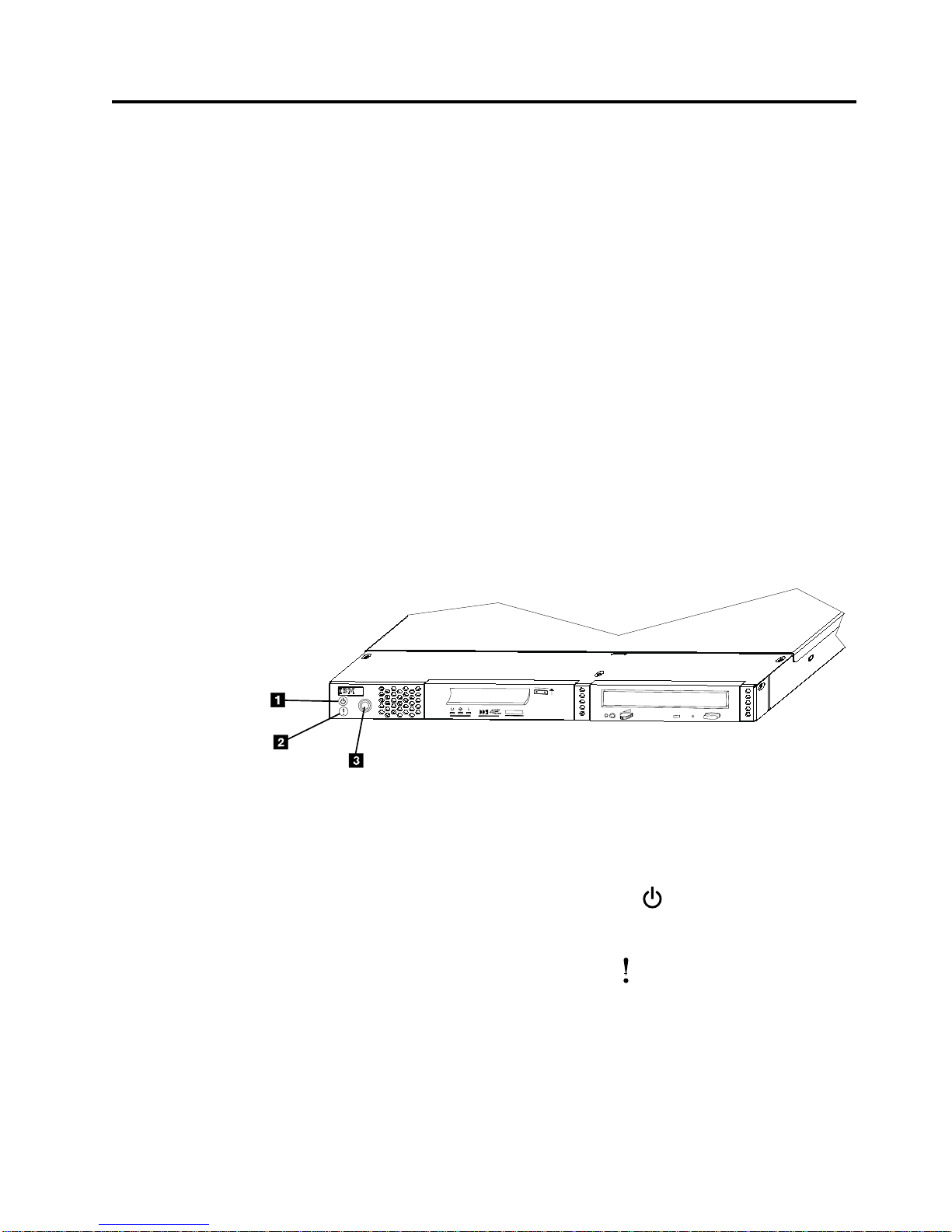
Figure 1 shows the 7212 Storage Enclosure with a DDS-4 4mm tape drive installed
Bay A and a DVD-RAM drive installed in Bay B.
7212
RBBTW504-0
BAY A
BAY B
Figure 1. Front view of the 7212 Storage Enclosure
The 7212 Storage Enclosure has the following components on the front of the unit:
Status Lights
The following status lights are located on the left front of the enclosure:
The Power-on light 1 is a green symbol
that illuminated when the
7212 Storage Enclosure is powered on and no fault condition exists for
the enclosure.
The fault light 2 is an amber symbol
that is illuminated when there
fault condition with the 7212 Storage Enclosure cooling fans.
Power
Switch
Bay A Bay A, on the left front of the 7212 Storage Enclosure (see Figure 1), can
Copyright IBM Corp. 2001, 2004
The power switch 3 is a push button switch that enables the power to be
turned on or off. Push and release the button to toggle power to the 7212
Storage Enclosure on and off.
accommodate any one of the four storage devices or a bay blank.
1
Page 16
If a
to
To
2
Bay B Bay B, on the right front of the 7212 Storage Enclosure (see Figure 1 on
page 1), can accommodate any one of the four storage devices or a bay
blank.
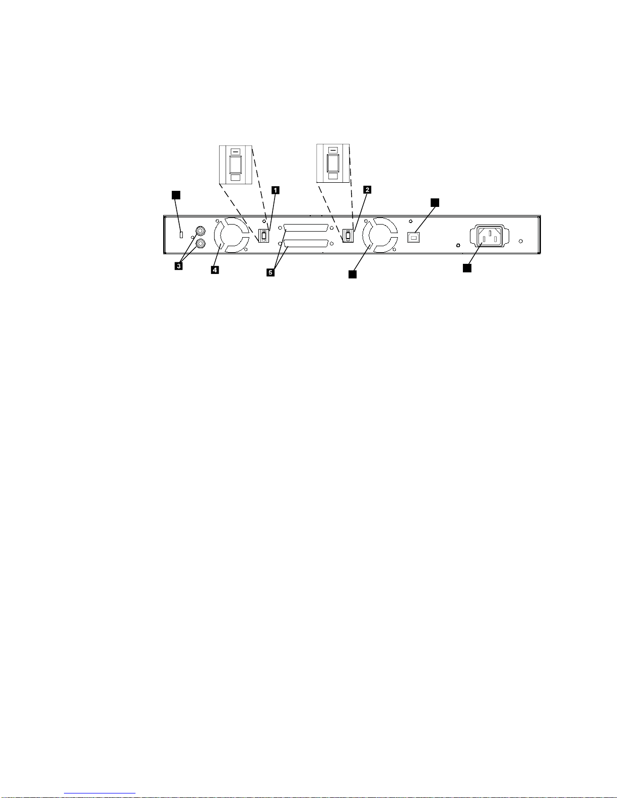
The rear of the 7212 Storage Enclosure has the following components:
3
+
5
+
9
3
+
5
+
6
Figure 2. Rear view of the 7210 DVD-RAM Drive
SCSI Address Switches
The Bay A 2 and Bay B 1 SCSI address switches are used to identify
the installed storage devices to the host system.
Note: The SCSI address switches are supplied as part of the device feature
kits since the various supported devices each have unique
requirements for the address switches. Therefore if no drive is
installed in a device bay, then no SCSI address switch is installed for
that bay.
Audio
Jack Connectors
DVD-ROM or DVD-RAM drive is installed in Bay B, the audio jack
connectors 3 can be used to attach the drive to a stereo amplifier.
7
8
RBBTV542-0
Note:
The audio jack connectors are supplied as part of the device feature
kits, since the various supported devices each have unique
requirements for the audio jack connectors. The audio jack
connectors are supplied only with the DVD-ROM Drive and the
DVD-RAM Drive feature kits. Audio jack connectors can only be
used for a DVD-ROM drive or DVD-RAM drive installed in device
bay B (see Figure 1 on page 1). If a DVD-ROM drive or DVD-RAM
drive is not installed in device bay B, no audio jack connectors are
installed in the 7212 Storage Enclosure.
Cooling Fans
The 7212 Storage Enclosure utilizes two internal cooling fans (4 and 6)
regulate the internal temperature of the enclosure. Air exits the 7212
Storage Enclosure at the two cooling fan locations.
Note:
the cooling fan exits at the rear of the enclosure and the air inlet
holes at the front of the enclosure have sufficient clearance to ensure
airflow.
7212 Storage Device Enclosure Service Guide
ensure proper operation, place the 7212 Storage Enclosure so that
Page 17

1.
2.
3.
4.
SCSI Bus Connectors
The 7212 Storage Enclosure provides two, 68 pin, rear mounted, SCSI bus
connectors 5 for attaching the 7212 Storage Enclosure to the host SCSI
bus. These two external SCSI connectors represent the two ends of the
internal SCSI bus cables. The internal SCSI bus cable can be configured to
support either a single SCSI bus with one host system or with a split SCSI
bus allowing SCSI connections to two hosts. Devices installed in the two
enclosure device bays are attached to the internal SCSI bus cables so that
the installed devices can be on a single or split SCSI bus.
Note: The SCSI interface mode (Low Voltage Differential or Single Ended)
that the 7212 Storage Enclosure will operate in, is dependent on the
type of drives installed in the 7212 Storage Enclosure and the host
system SCSI adapter type.
Signal USB Port
Fault
The rear of the 7212 Storage Enclosure has a Fault Signal USB Series B Port
7. This port is provided for installations that have provisions for remote
fault monitoring of devices. If the 7212 Storage Enclosure experiences a
fault condition (power loss or fan failure) the Pin 2 signal of the USB port
will go from a high state to a low state.
Power
Security Clip Hole
System Requirement
The following sections describe the host system requirements for the 7212 Model
102 Storage Enclosure:
Notes:
The USB port pin 2 is an open collector and must be connected to a
monitoring receiver that is active for the port to have a valid output
signal.
Pin 2 signal voltage is dependent on the electrical design of the
monitoring receiver.
Pin 4 is ground.
Pins 1 and 3 are not connected.
Cable Connector
The 7212 Storage Enclosure receives power through a cable connected to
the power cable connector 8.
The 7212 Storage Enclosure can be secured to a rack or other stationary
object using a security cable and clips that are inserted into the security
clip hole 9 and then attached to a secure object. Contact your IBM
marketing representative or business partner to purchase a security cable.
RS/6000 and pSeries Systems
The 7210 Model 025 DVD-RAM Drive requires a host system platform with an AIX
operating system at level 4.3.3 with update CD LCD4-0995-14 or AIX level 5.1 with
update CD LCD4-1103-01 or higher.
For a list of supported processors and adapters, contact your IBM marketing
representative or business partner.
Chapter 1. General Information
3
Page 18
1
3
No 10 m
No
No
No
No No 1
2
3
4
AS/400 and iSeries Systems
The 7212 Storage Enclosure requires only a supported AS/400 or iSeries system
processor with an OS/400 operating system at level V5R1 (or higher) and a PCI
Magnetic Media Controller (FC 2718 or FC 2768) or a PCI-X ULTRA TAPE
CONTROLLER (FC 5702) or PCI-X TAPE/DASD CONTROLLER (FC 5705). See the
order configurator information for the correct controller to be used for your host
system model.
For a list of supported processors and adapters, contact your IBM marketing
representative or business partner.
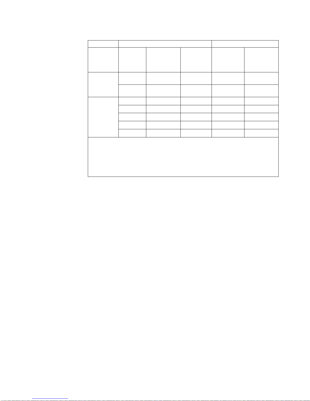
SCSI Bus Cables
The following table shows the various SCSI cable feature codes that can be ordered
depending on the host system adapter to which the product will be attached.
Table 1. SCSI Cable Features for pSeries or RS/6000
pSeries &
RS/6000
Adapter
Feature
6203, 6205,
Integrated
Ultra2 SCSI
Adapter, or
Integrated
Ultra3 SCSI
Adapter
(LVD/SE) or
5703, 5710,
5711, 5712
PCI-X
Adapter
6206 Ultra
SCSI Adapter
(SE)
configuration.
SCSI Cable Description
Length
0.5 m
1.5 m
2.5 m
4.5 m
Connectors MES Feature
VHDCI/HD68 5600/9765
VHDCI/HD68 5601/9761
VHDCI/HD68 5602/9762
VHDCI/HD68 5604/9764
VHDCI/HD68 5610/9760
0.5 m
0.7 m
1.5 m
2.5 m
5.0 m
HD68/HD68 5303/9733
HD68/HD68 5301/9751
HD68/HD68 5300/9750
HD68/HD68 5302/9752
HD68/HD68 5305/9755
Cable
SCSI Cable Application
Adapter to
7212-102
7212-102 to
2nd Device
Yes
Yes
Yes
Yes
Yes
Yes
Yes
Yes
Yes
Use Table 3 on page 6 to determine the maximum SCSI cable length per SCSI bus
Yes
Yes
Yes
Yes
Yes
The SCSI Terminator feature for all 7212 cable configurations is 5097.
Attaching a second device to the SCSI bus after the 7212 Storage enclosure is only
supported when the internal SCSI cable is configured with a single SCSI bus.
Note: For more detailed descriptions of these cables, contact your IBM marketing
representative or business partner.
7212 Storage Device Enclosure Service Guide
Page 19
1
3
No
No
No
No 1
2
3
Table 2. SCSI Cable Features for iSeries or AS/400
iSeries &
AS/400
SCSI Cable Description
Length
Connectors MES Feature
Cable
SCSI Cable Application
Adapter to
7212-102
7212-102 to
2nd Device
Adapter
Feature
2718, 2768
1.5 m
HD68/HD68 5300/9750
Yes
Yes
Magnetic
Media
2.5 m
HD68/HD68 5302/9752
Yes
Controller
5702, 5703,
5705, 5710,
5711, 5712,
5715 PCI
Adapters
0.5 m
1.5 m
2.5 m
4.5 m
VHDCI/HD68 5600/9765
VHDCI/HD68 5601/9761
VHDCI/HD68 5602/9762
VHDCI/HD68 5604/9764
10.0 m VHDCI/HD68 5610/9760
Yes
Yes
Yes
Yes
Yes
Yes
Yes
Use Table 4 on page 7 to determine the maximum SCSI cable length per SCSI bus
configuration.
The SCSI Terminator feature for all 7212 cable configurations is 5097.
Attaching a second device to the SCSI bus after the 7212 Storage enclosure is only
supported when the internal SCSI cable is configured with a single SCSI bus.
Note: For more detailed descriptions of these cables, contact your IBM marketing
representative or business partner.
Chapter 1. General Information
5
Page 20

NA
or
NA
or
1
NA 9 m 9 m 10 m 10 m
9 m 9 m 9 m 10 m 10 m
9 m 9 m 9 m 10 m 10 m
10 m 10 m 10 m 10 m 10 m
or
10 m 10 m
1
NA 10 m 10 m 10 m 10 m
10 m 10 m 10 m 10 m 10 m
10 m 10 m 10 m 10 m 10 m
10 m 10 m 10 m 10 m 10 m
or
10 m 10 m 10 m 10 m 10 m 1
6
Table 3 details the maximum total length external SCSI cable for each configuration
supported on the 7212 Storage Enclosure connected to an RS/6000 or pSeries host.
Table 3. Maximum SCSI Cable Lengths per Configuration for RS/6000 or pSeries
pSeries or RS/6000
SCSI Bus
Configuration
6206 Ultra SCSI
adapter with one
7212 Enclosure per
adapter port
6203, 6205, Integrated
Ultra2 SCSI, or
Integrated Ultra3
SCSI adapter or 5703,
5710, 5711, 5712
PCI-X adapter with
one 7212 Enclosure
per adapter port
Device in
7212 Bay A
Blank
DDS-4 or
DAT 72
VXA
SLR60 or
SLR100
DVD-RAM
DVD-ROM
Blank
DDS-4 or
DAT 72
VXA
SLR60 or
SLR1000
DVD-RAM
Blank
1.5 m
1.5 m
1.5 m
1.5 m
10.5 m
10.5 m
10.5 m
1.5 m
DDS-4 or
DAT 72
1.5 m
1.5 m
1.5 m
1.5 m
1.5 m
10.5 m
10.5 m
10.5 m
10.5 m
1.5 m
Device in 7212 Bay B
VXA
1.5 m
1.5 m
1.5 m
1.5 m
1.5 m
10.5 m
10.5 m
10.5 m
10.5 m
1.5 m
SLR60 or
SLR100
1.5 m
1.5 m
1.5 m
1.5 m
1.5 m
10.5 m
10.5 m
10.5 m
10.5 m
1.5 m
DVD-RAM or
DVD-ROM
1.5 m
1.5 m
1.5 m
1.5 m
1.5 m
10.5 m
10.5 m
10.5 m
10.5 m
1.5 m
DVD-ROM
6203, 6205, Integrated
Ultra2 SCSI, or
Integrated Ultra3
SCSI adapter or 5703,
5710, 5711, 5712
PCI-X adapter with
two 7212 Enclosures
per adapter port
Blank
DDS-4 or
DAT 72
VXA
SLR60 or
SLR100
DVD-RAM
Not Supported
Not
Supported
Not
Supported
DVD-ROM
6203, 6205, Integrated
Ultra2 SCSI, or
Integrated Ultra3
SCSI adapter or 5703,
5710, 5711, 5712
PCI-X adapter with
one 7212 Enclosure
and one LVD Single
Device Bridge Box
Blank
DDS-4 or
DAT 72
VXA
SLR60 or
SLR100
DVD-RAM
per adapter port
DVD-ROM
Attaching a second device to the SCSI bus after the 7212 Storage enclosure is only supported when the internal
SCSI cable is configured with a single SCSI bus.
7212 Storage Device Enclosure Service Guide
Page 21

NA
NA
1
NA
1
NA
1
Table 4 details the maximum total length external SCSI cable for each configuration
supported on the 7212 Storage Enclosure connected to an AS/400 or iSeries host.
Table 4. Maximum SCSI Cable Lengths per Configuration for AS/400 or iSeries
iSeries or AS/400 SCSI
Bus Configuration
2718, 2768 Magnetic
Media Controller with
one 7212 Enclosure per
adapter port
6203, 6205, Integrated
Ultra2 SCSI, or
Integrated Ultra3 SCSI
adapter or 5702, 5703,
5710, 5711, 5712, 5715
PCIX adapter with one
7212 Enclosure per
adapter port
6203, 6205, Integrated
Ultra2 SCSI, or
Integrated Ultra3 SCSI
adapter or 5703, 5710,
5711, 5712, 5715 PCIX
adapter with two 7212
Enclosures per adapter
port
6203, 6205, Integrated
Ultra2 SCSI, or
Integrated Ultra3 SCSI
adapter with one 7212
Enclosure and one LVD
Single Device Bridge
Box per adapter port
Attaching a second device to the SCSI bus after the 7212 Storage enclosure is only supported when the internal
SCSI cable is configured with a single SCSI bus.
Device in 7212
Bay A
Blank
VXA
SLR60 or
SLR100
DVD-RAM or
DVD-ROM
Blank
VXA
SLR60 or
SLR100
DVD-RAM or
DVD-ROM
Blank
VXA
SLR60 or
SLR100
DVD-RAM or
DVD-ROM
Blank
VXA
SLR60 or
SLR100
DVD-RAM or
DVD-ROM
Blank
2.5 m
2.5 m
2.5 m
10.0 m
10.0 m
10.0 m
10.0 m
10.0 m
10.0 m
10.0 m
10.0 m
10.0 m
Device in 7212 Bay B
VXA
2.5 m
2.5 m
2.5 m
2.5 m
10.0 m
10.0 m
10.0 m
10.0 m
10.0 m
10.0 m
10.0 m
10.0 m
10.0 m
10.0 m
10.0 m
10.0 m
SLR60 or
SLR100
2.5 m
2.5 m
2.5 m
2.5 m
10.0 m
10.0 m
10.0 m
10.0 m
10.0 m
10.0 m
10.0 m
10.0 m
10.0 m
10.0 m
10.0 m
10.0 m
DVD-RAM or
DVD-ROM
2.5 m
2.5 m
2.5 m
2.5 m
10.0 m
10.0 m
10.0 m
10.0 m
10.0 m
10.0 m
10.0 m
10.0 m
10.0 m
10.0 m
10.0 m
10.0 m
Chapter 1. General Information
7
Page 22

44 mm
V AC
50 to 60
16 to
10 to
20 to
8 to
1
8
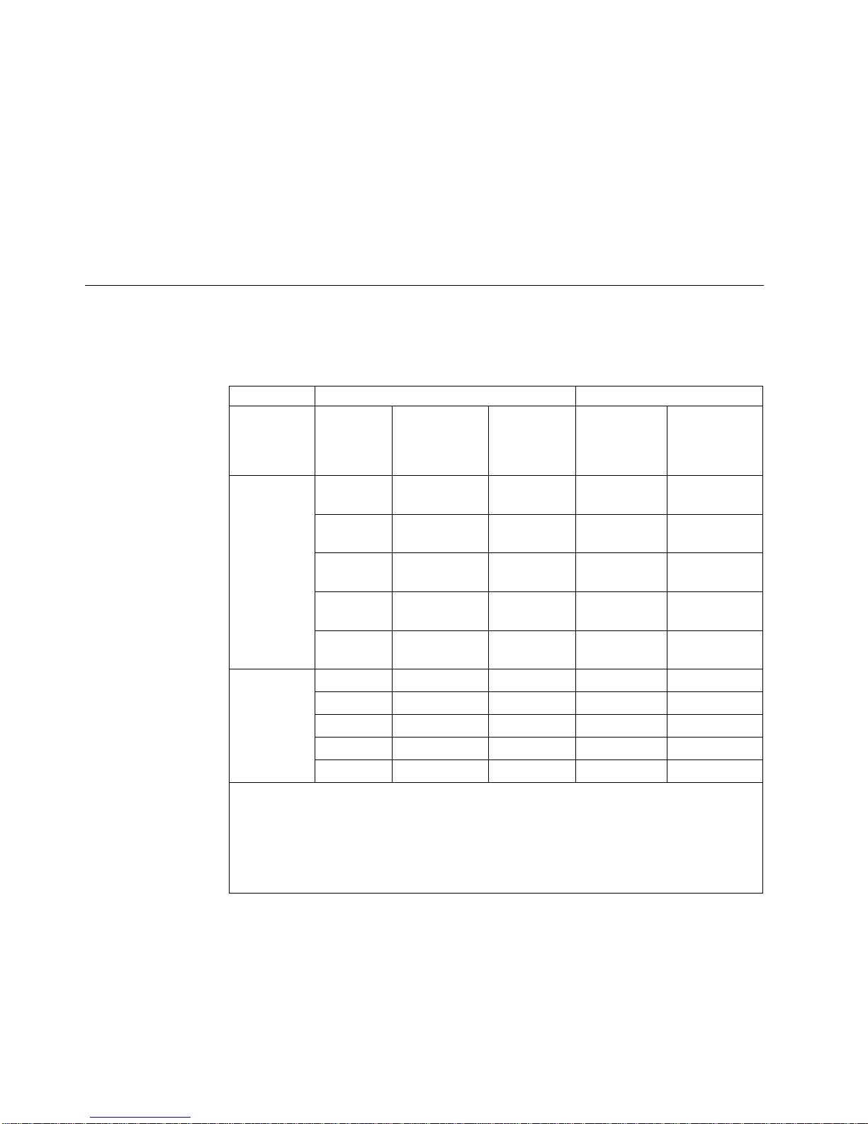
Specifications
Table 5. Specifications for the 7212 Model 102 Storage Device Enclosure
Physical Specifications
Width
Depth
Height
Weight
428 mm (16.85 in.)
483 mm (19.0 in.)
(1.72 in.)
8.3 kg (18.2 lb)
1
Power Specifications
kVA
0.047 @ 120 V AC
100 to 125, or 200 to 240
Hertz
Btu Maximum (watts)
Power Factor
Altitude
205 Btu/hr (60 watts) @ 240 V AC
0.8 to 0.9
2135 m (7000 ft)
Performance Specifications
Dependant on device, media type, and SCSI bus configuration.
Recommended Environment
Environmental Factor
Temperature
Operating
32°C
Non-operating
52°C
(60 to 90°F)
Relative Humidity
80%
(noncondensing)
Maximum Wet Bulb
23°C
(73°F)
Weight with two DDS-4, 4mm tape drives installed and no rack slides.
(50 to 126°F)
80%
23°C
(73°F)
7212 Storage Device Enclosure Service Guide
Page 23

a
to
a
we
it
is
a
No
Media Drive Environment and Use
IBM’s goal is to provide you with a product that you can configure and use
reliably. Removable media drives require specific maintenance and environmental
conditions to operate well over time. Using high quality, data grade media,
handling and storing this media properly, operating the removable media drive in
clean environment and keeping the removable media drive properly cleaned can
help you to avoid problems with your IBM product.
Media Grades
IBM may use two different grades of media. At the discretion of IBM, Program
Transmittal Fixes (PTFs) may be supplied on media that is designed to be written
only once and read from several times. This media is not designed to be used as
backup medium.
IBM also sells media designed to be used for storage. IBM supports the media that
sell. If IBM service personnel analysis indicates a problem with non-IBM media
may be necessary for the customer to replace the media.
Media Handling and Storage
Most media is supplied in a sealed cartridge. It is provided this way so that the
media will remain in a clean environment. Opening the cartridge allows dirt and
airborne particles to enter and then become a source of contamination. The
cartridge should only be opened by the drive and not an operator. The media also
held under proper tension inside the cartridge. If the cartridge is dropped, this
tension will be relaxed. Inserting a dropped cartridge into a drive can cause
incorrect loading and result in a jam. This will ruin the media and can cause
physical damage if the cartridge is not removed properly.
When the media is stored, it must be replaced in the protective containers and
stored on the end. The storage area must be clean, dry, normal room temperature
and away from any magnetic fields.
Environmental Issues
Removable media drives are designed to operate in a clean environment. Problem
factors are dirt, dust, fibers and airborne particles. Airborne particles are the most
difficult to address. When media is installed in the drive, the clearance between the
heads and the media is measured in microns. Particles can damage the media or
the head if they come in contact with either. Customers are responsible to provide
clean operating environment for the drive and system.
Drive Cleaning
matter how clean the environment, debris may build up on the heads of any
drive. Over time, this builds up and causes errors in reading and writing.
Customers are responsible to clean the drive in accordance with the cleaning
information provided with the drive.
IBM only supports the use of IBM cleaning cartridges for IBM drives.
Chapter 1. General Information
9
Page 24

If a
or
10
SCSI Hardware Issues
SCSI bus cables and terminators may affect drive performance. IBM cables and
terminators are designed specifically to keep the SCSI bus as free of noise as
possible. Use of non-IBM cables or terminators may adversely affect the SCSI bus
performance. If IBM service personnel analysis indicates a problem with non-IBM
cables, it may be necessary for the customer to replace them with the appropriate
IBM cables.
Microcode Updates
IBM constantly works to provide the best possible products. To make certain that
the drives work their very best, IBM occasionally releases changed microcode for
the drives. When a microcode change is developed, IBM makes it available to you
through the service organization or by electronic delivery.
For RS/6000 and pSeries Host Systems
Microcode changes are available from the following IBM Web site:
http://techsupport.services.ibm.com/server/mdownload
Microcode can be installed by your IBM authorized service personnel or your
system administrator.
For AS/400 and iSeries Host Systems
AS/400 and iSeries system technical support is available from the following IBM
Web site:
http://www-912.ibm.com/
Microcode can be installed by your IBM authorized service personnel or your
system administrator.
Summary
Your drive must be installed in the cleanest possible environment. Additionally,
IBM drives require high quality, data grade media and cleaning on a regular basis.
Media must also be stored and handled properly. Improper use, storage or
handling of drives or media may void your IBM warranty or service agreement
defective drive under the terms and conditions of the IBM warranty or service
agreement. It is our objective to work with you to identify the cause of any drive
problems and provide a solution.
drive stops functioning due to a component failure during the drive warranty
maintenance time, IBM will replace the drive unit. IBM will replace any
7212 Storage Device Enclosure Service Guide
Page 25
on
or
to
Do
If a
to
©
Chapter 2. Maintenance Analysis Procedures
DANGER
prevent a possible electrical shock from touching two surfaces with
To
different electrical grounds, use one hand, when possible, to connect or
disconnect signal cables. (RSFTD004)
DANGER
electrical outlet that is not correctly wired could place hazardous voltage
An
metal parts of the system or the products that attach to the system. It is the
customer’s responsibility to ensure that the outlet is correctly wired and
grounded to prevent an electrical shock. (RSFTD201)
CAUTION:
Ensure that all rack-mounted units are fastened in the rack frame. Do not extend
exchange any rack-mounted units when the stabilizer is not installed.
(RSFTC222)
CAUTION:
When the unit is extended, its weight can turn over a rack that is not steady.
Before you pull the unit out of the rack, ensure that a rack stabilizer is attached
the bottom front of the rack.
not pull out more than one unit at a time. The rack can turn over if you pull
out more than one unit at a time. (RSFTC224)
Purpose of the MAPs
Maintenance analysis procedures (MAPs) are used to check the:
Power cable
Power supply
Terminator
problem is detected, the procedure isolates the problem to the failing field
replaceable unit (FRU).
SCSI address
SCSI cable
Configuration
Drive
Fan
For instructions about removing or replacing a FRU, refer to Chapter 3, “Removal
and Replacement Procedures,” on page 27
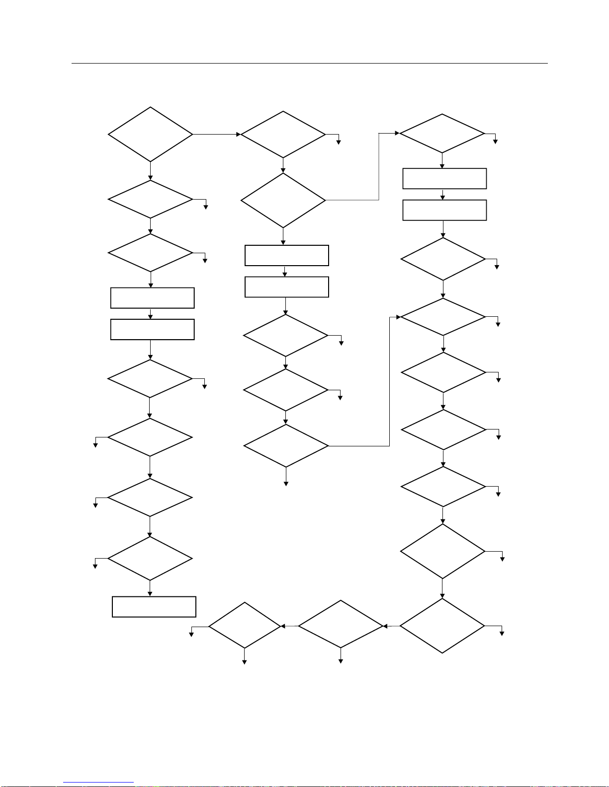
The following flowchart provides a graphic to be used as a guide to the MAP. For
detailed instructions on how to perform each procedure safely and correctly, refer
the steps in this chapter.
Copyright IBM Corp. 2001, 2004
11
Page 26

12
Flowchart of the MAPs (RS/6000 and pSeries Systems)
no
Replace power
switch and
return to Step 1
no
Replace power
supply and
return to Step 1
no
Replace status
interface card and
return to Step 1
Step 1
Does the
7212-102
power up?
no
Step 2
Electrical outlet
OK?
Contact service
yes
Step 3
Power cable
OK?
yes
Exchange
power cable
Shut the system down
and power off
Remove cover and
prepare unit
Step 4
Any visual
problem?
Fix problem and
no
Step 5
Power Switch
OK?
yes
Step 6
Power Supply
OK?
yes
Step 7
Status interface
card OK?
yes
Replace the LED cable
and return to Step 1
yes
no
personnel
no
yes
return to Step 1
Step 8
Are either of the
fans bad?
no
Step 9
Did drive
complete
POST?
Shut the system down
and power off
Remove cover and
prepare unit
Step 10
Any visual
problem?
Step 11
Power distribution
cable OK?
Step 12
Drives power
up normal?
Replace failing
drive and
return to Step 1
Fail
Replace FRU/contact
service personnel
yes
Replace
fans and
return to Step 1
no
yes
Fix problem and
return to Step 1
no
no
Replace power
distribution cable and
yes
return to Step 1
yes
no
Step 20
Run AIX
diagnostics
Problem fixed
yes
Pass
Step 13
Media
OK?
yes
and return to Step 1
Shut the system down
and power off
Remove cover and
prepare unit
Step 14
Any visual
problem?
Fix problem and
no
return to Step 1
Step 15
SCSI Address
OK?
yes
Step 16
Internal SCSI
cable OK?
Replace SCSI
yes
return to Step 1
Step 17
External SCSI
cable OK?
Replace SCSI
yes
return to Step 1
Step 18
Terminator
OK?
yes
terminator and
return to Step 1
Step 19
Run Configuration
Manager
no
Replace media
yes
no
Fix SCSI
address and
return to Step 1
no
cable and
no
cable and
no
Replace
RBBTW521-0
Figure 3. RS/6000 and pSeries Systems Flowchart of the Maintenance Analysis Procedures (MAPs)
7212 Storage Device Enclosure Service Guide
Page 27
Flowchart of the MAPs (AS/400 and iSeries Systems)
no
Replace power
switch and
return to Step 1
no
Replace power
supply and
return to Step 1
no
Replace status
interface card and
return to Step 1
Step 1
Does the
7212-102
power up?
no
Step 2
Electrical outlet
OK?
Contact service
yes
Step 3
Power cable
OK?
yes
Exchange
power cable
Shut the system down
and power off
Remove cover and
prepare unit
Step 4
Any visual
problem?
Fix problem and
no
Step 5
Power Switch
OK?
yes
Step 6
Power Supply
OK?
yes
Step 7
Status interface
card OK?
yes
Replace the LED cable
and return to Step 1
Retry and
replace
on failure
yes
no
personnel
no
yes
return to Step 1
no
Are either of the
Shut the system down
Remove cover and
Step 24
Did the Verify
test pass?
yes
Problem fixed
Step 8
fans bad?
no
Step 9
Did drive
complete
POST?
no
and power off
prepare unit
Step 10
Any visual
problem?
no
Step 11
Power distribution
cable OK?
distribution cable and
yes
Step 12
Drives power
up normal?
no
Replace failing
drive and
return to Step 1
fail
yes
Replace
fans and
return to Step 1
yes
yes
Fix problem and
return to Step 1
no
Replace power
return to Step 1
yes
Step 23
Clean the
drives and
retry
pass
Problem
fixed
Shut the system down
and power off
Remove cover and
prepare unit
Any visual
SCSI Address
Internal SCSI
cable OK?
External SCSI
cable OK?
Terminator
Are the devices
configured to
Are the devices
communicating with
yes
the system?
Step 13
Media
OK?
yes
Step 14
problem?
no
Step 15
OK?
yes
Step 16
yes
Step 17
yes
Step 18
OK?
yes
Step 21
system?
no
Step 22
RBBTW528-0
no
Replace media
and return to Step 1
yes
Fix problem and
return to Step 1
no
Fix SCSI
address and
return to Step 1
no
Replace SCSI
cable and
return to Step 1
no
Replace SCSI
cable and
return to Step 1
no
Replace
terminator and
return to Step 1
yes
Go to
Step 20
no
Contact support
personnel
Figure 4. AS/400 and iSeries Systems Flowchart of the Maintenance Analysis Procedures (MAPs)
Chapter 2. Maintenance Analysis Procedures
13
Page 28
on
1.
2.
3.
go to
On
On
1.
2.
3.
NO
Go to
NO
Go to
14
Step 1
DANGER
electrical outlet that is not correctly wired could place hazardous voltage
An
metal parts of the system or the products that attach to the system. It is the
customer’s responsibility to ensure that the outlet is correctly wired and
grounded to prevent an electrical shock. (RSFTD201)
This step verifies whether the power is operating properly.
Make sure that the 7212 Storage Enclosure power cable is plugged into an
electrical outlet.
Press the Power On button on the 7212 Storage Enclosure.
Check the state of the power On and Fault lights on the front of the 7212
Storage Enclosure.
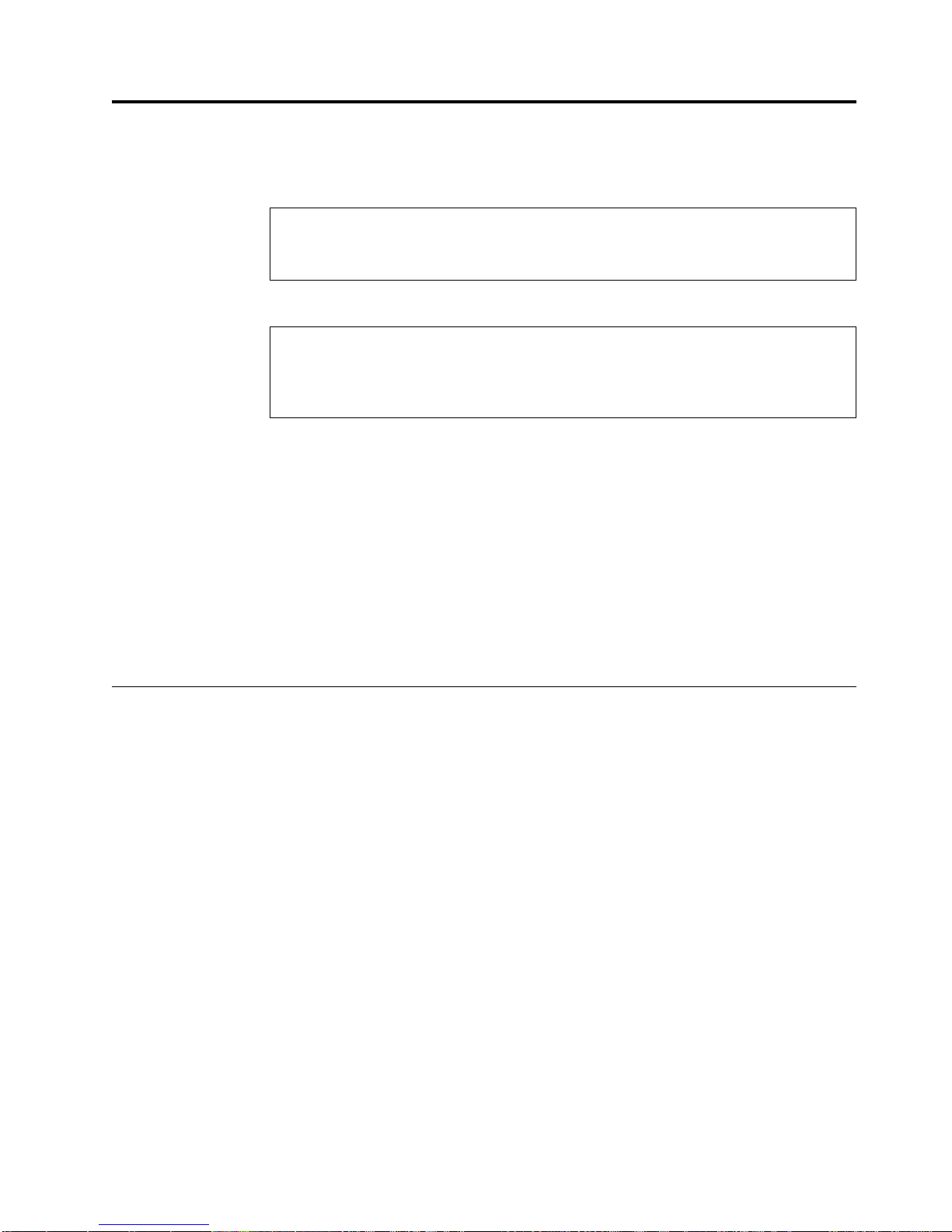
Table 6. Status Light States
Power-On
Light Status
Off
Off
Fault Light
Status
Off
Off
Service Action
Repeat Step 1 several times. If neither light illuminates, then
Step 2.
This indicates normal operation. Go to Step 9.
This indicates that there may be a fan failure. Go to Step 8.
Step 2
Step 3
This step tests the voltage at the electrical outlet.
Press the 7212 Storage Enclosure power switch to turn off the power.
Unplug the 7212 Storage Enclosure power cable from the electrical outlet and
from the 7212 Storage Enclosure.
Measure the voltage at the electrical outlet.
the voltage from the electrical outlet correct?
Is
Contact your service personnel for further instructions.
YES
Step 3.
This step determines whether the power cable is functional.
Make sure that all of the conductors in the power cable have continuity, and that
there are no short circuits.
Does the power cable have continuity and are there no short circuits?
Replace the power cable, then go to Step 1.
YES
Step 4.
7212 Storage Device Enclosure Service Guide
Page 29

1. Do a
2.
3.
4.
5.
6.
7.
NO
If
1.
2.
On or In
3.
On
NO
in
to
Step 4
This step performs a visual and physical check in an attempt top fix the problem.
controlled system shutdown (refer to the instructions in the 7212 Model
102 Storage Device Enclosure Setup and Operator Guide).
Ensure that the power to the host is off.
Turn off the power to the 7212 Storage Enclosure.
Unplug the 7212 Storage Enclosure from the electrical source.
Perform the cover removal procedure. Refer to “Removing and Replacing the
Cover” on page 28.
Visually inspect all of the internal components in the enclosure. Look for any
signs of wear, damage, contamination, or excessive heat.
Physically check each cable connection and ensure all cables are fully seated
and secured.
Are their any signs of damage, wear, or loose cables?
Step 5
Plug the enclosure into an electrical source and press the power On
switch to determine if the connection inspection fixed the problem.
the enclosure does not power on, go to Step 5. If the enclosure
powers on and appears to run normally, reassemble the enclosure,
and then return to Step 1.
YES
Replace the damaged component or reseat the cable, reassemble
the enclosure and then return to Step 1.
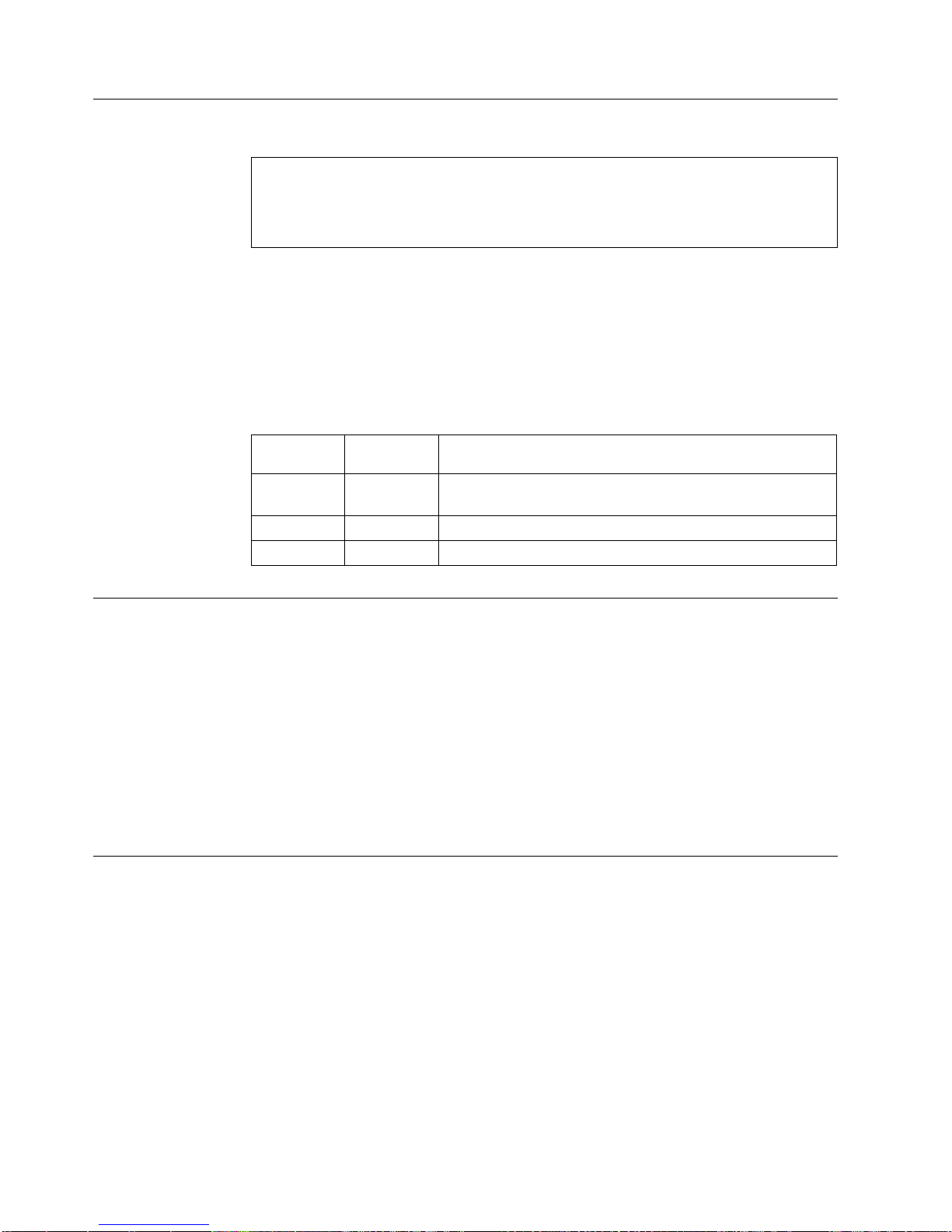
This step checks the Power On/Off switch to determine if this is the source of the
problem.
Unplug the 7212 Storage Enclosure from the electrical source.
Press the power switch on the enclosure to determine whether it latches in the
position.
Unplug the power switch cable from the power supply and test the electrical
continuity of the cable pins, as illustrated in Table 7.
Table 7. Power Switch Cable Pin Continuity
Power button
position
Off (out)
(in)
Continuity between
cable pins 1 and 2
Open Circuit
Continuity
Continuity between
cable pins 3 and 4
Open Circuit
Continuity
Continuity between
other cable pin pairs
Open Circuit
Open Circuit
Does the power switch latch in the On position and support the continuity as
shown in Table 7?
YES
Adjust the power switch bracket to ensure the button moves freely
the chassis hole. If the power button does not latch in the On
position or if the cable does not have continuity, replace the power
switch assembly (see “Removing and Replacing the Power Switch
Assembly” on page 36), reassemble the enclosure, and then return
Step 1.
Reassemble the power switch assembly and then go to Step 6.
Chapter 2. Maintenance Analysis Procedures
15
Page 30

1.
2.
3.
4.
5.
6.
7. On
v
v
NO
1.
2.
3.
4.
5.
6.
16
Step 6
This step checks the power supply voltage levels as the possible source of the
problem.
Press the power switch to turn off the power to the 7212 Storage Enclosure.
Unplug the 7212 Storage Enclosure from the electrical outlet.
Disconnect the power supply connector (J1) from the internal power
distribution cable.
Connect the power cable to both the 7212 Storage Enclosure and to the
electrical outlet.
Press the power switch to turn on the power.
Ensure the fan is operating on the power supply.
the power supply connector J1 (see Figure 5), check the following:
The +12V signal falls between a minimum of +11.5 volts and a maximum of
+12.6 volts
The +5V signal falls between a minimum of +4.8 volts and a maximum of
+5.25 volts
Step 7
Figure 5. Power Supply Connector J1
Are the voltages good, and is the power supply fan operating?
Replace the power supply (see “Removing and Replacing the
Power Supply” on page 33), reassemble the enclosure, and then
return to Step 1.
YES
Reconnect the power supply to the internal power distribution
cable and then go to Step 7.
This step checks the LED cable as the possible source of the problem.
Press the power switch to turn off the power to the 7212 Storage Enclosure.
Unplug the 7212 Storage Enclosure from the electrical outlet.
Disconnect the LED cable from the status interface card.
Connect the power cable to both the 7212 Storage Enclosure and to the
electrical outlet.
Press the power switch to turn on the power to the enclosure.
Check the voltage on the status interface card J1 connector pins with the 7212
cooling fans set to the states listed in Table 8 on page 17. This table lists the
front panel status light states that would occur if the LED cable is plugged into
the J1 connector.
The fans can be turned to an OFF state by disconnecting the fan cable from
Note:
the status interface board.
7212 Storage Device Enclosure Service Guide
Page 31

J1
J1
3
0v
On On
0v
On
0v On
0v
Do
NO
to
1.
2.
3.
NO Go to
1.
2.
NO If
Go to
Table 8. Status Interface Card Voltages
voltage
between
pins 1 and 2
voltage
between pins
and 4
4.8v < x <
7212
Right-side
cooling fan
7212 Left-side
cooling fan
7212 front
panel power
light
Green
7212 front
panel fault
light
Off
5.4v
4.8v < x <
Off
Off
Yellow
5.4v
4.8v < x <
Off
Off
Yellow
5.4v
4.8v < x <
Off
Off
Off
Yellow
5.4v
the voltages measured on the status interface board J1 connector comply
with Table 8?
Replace the status interface card (see “Removing and Replacing the
Power Supply” on page 33), reassemble the enclosure, and then
return to Step 1.
Step 8
Step 9
YES
Replace the LED cable, reassemble the enclosure, and then return
Step 1.
This step examines the cooling fan as the possible source of the problem.
Press the power switch to turn on the power to the 7212 Storage Enclosure.
Observe the fault light on the front of the enclosure.
Observe the cooling fans on the rear of the enclosure. Ensure the fans are
blowing air out of the enclosure and that they are operating at a constant
speed, not making abnormal noises.
the fault light come on and stay on, or are either of the fans operating
Does
abnormally?
Step 9.
YES
Replace the failing cooling fan (see “Removing and Replacing the
Cooling Fans” on page 35), and then return to Step 1.
This step examines the drive as the possible source of the problem.
Press the power switch to turn on the power to the 7212 Storage Enclosure.
Observe each of the drive status indicator lights during & after POST.
the drives power up and complete the Power On Self Test (POST) normally?
Do
YES
the drives do not power up, go to Step 10. If the drives power
up, but with status lights reporting an error condition follow the
recommended drive service action as appropriate (refer to the
drive descriptive chapters in the 7212 Model 102 Storage Device
Enclosure Setup and Operator Guide), and then go to Step 1.
Step 13.
Chapter 2. Maintenance Analysis Procedures
17
Page 32

1. Do a
2.
3.
4.
5.
6.
7.
NO
If
1.
2.
3.
4.
5.
6.
7. On
v
v
18
Step 10
This step performs a visual and physical check in an attempt top fix the problem.
controlled system shutdown (refer to the instructions in the 7212 Model
102 Storage Device Enclosure Setup and Operator Guide).
Ensure that the power to the host is off.
Turn off the power to the 7212 Storage Enclosure.
Unplug the 7212 Storage Enclosure from the electrical source.
Perform the cover removal procedure. Refer to “Removing and Replacing the
Cover” on page 28.
Visually inspect all of the internal components in the enclosure. Look for any
signs of wear, damage, contamination, or excessive heat.
Physically check each cable connection and ensure all cables are fully seated
and secured.
Are their any signs of damage, wear, or loose cables?
Step 11
Plug the enclosure into an electrical source and press the power On
switch to determine if the connection inspection fixed the problem.
the enclosure does not power up normally, go to Step 11. If the
enclosure powers on and appears to run normally, reassemble the
enclosure, and then return to Step 1.
YES
Replace the damaged component or reseat the cable, reassemble
the enclosure and then return to Step 1.
This step checks the power distribution cable as the possible source of the problem.
Press the power switch to turn off the power to the 7212 Storage Enclosure.
Disconnect the power distribution cable from the device installed in Bay A.
Disconnect the power distribution cable from the device installed in Bay B.
Disconnect the power distribution cable from the status interface card.
Connect the power cable to both the 7212 Storage Enclosure and to the
electrical outlet.
Press the power switch to turn on the power.
each of the three device power distribution cable connectors (see Figure 6),
check the following:
The +12V signal falls between a minimum of +11.5 volts and a maximum of
+12.6 volts
The +5V signal falls between a minimum of +4.8 volts and a maximum of
+5.25 volts
Figure 6. Device Power Cable Connector
7212 Storage Device Enclosure Service Guide
Page 33

NO
1.
2.
3.
NO
1.
2.
3.
NO If
1. Do a
2.
3.
4.
Are the voltages good at each connector?
Replace the power distribution cable (see “Removing and
Replacing the Power Distribution Cable” on page 39), reassemble
the enclosure, and then return to Step 1.
Step 12
Step 13
YES
Reattach the power cables to the devices and then go to Step 12.
This step examines the drives as the possible source of the problem.
Press the power switch to turn off the power to the 7212 Storage Enclosure.
Disconnect the power distribution cable, SCSI cable, and SCSI address cable
from the drive in Bay A.
Press the power switch to turn on the power.
the drive in Bay B power up and complete the Power On Self Test (POST)
Does
normally?
Turn off the power, reconnect the cables to the drive in Bay A, and
then disconnect the cables from the back of the drive in Bay B. If
the drive in Bay A then powers on normally, replace the drive in
Bay B and then return to Step 1. If not, go to Step 15.
YES
Replace the drive in Bay A and then return to Step 1.
This step checks whether the media is the source of the problem.
Press the media unload button on the drive (refer to the drive descriptive
chapters in the 7212 Model 102 Storage Device Enclosure Setup and Operator
Guide).
Remove the used media. If the media fails to unload, refer to drive specific
chapters (4, 5, and 6) in this manual for manual media unload procedures.
Power the 7212 Storage Enclosure off and then back on. Insert new media and
then power the 7212 Storage Enclosure off and then back on.
the installed drives power up and complete the POST normally?
Do
YES
Step 14
This step performs a visual and physical check in an attempt top fix the problem.
102 Storage Device Enclosure Setup and Operator Guide).
Ensure that the power to the host is off.
Turn off the power to the 7212 Storage Enclosure.
Unplug the 7212 Storage Enclosure from the electrical source.
the drives do not power up, go to Step 11. If the drives power
up, but with status lights reporting an error condition, follow the
recommended drive service action (refer to the drive descriptive
chapters in the 7212 Model 102 Storage Device Enclosure Setup and
Operator Guide), and then go to Step 1.
Discard the used media and then go to Step 14.
controlled system shutdown (refer to the instructions in the 7212 Model
Chapter 2. Maintenance Analysis Procedures
19
Page 34

6.
7.
8.
NO
If
is
NO
To
to
Go to
1.
2.
3.
4.
Is
NO
to
20
5.
Perform the cover removal procedure. Refer to “Removing and Replacing the
Cover” on page 28.
Visually inspect all of the internal components in the enclosure. Look for any
signs of wear, damage, contamination, or excessive heat.
Physically check each cable connection and ensure all cables are fully seated
and secured.
Ensure that the internal SCSI cables are connected correctly for the desired SCSI
configuration (split or single SCSI bus.)
Are their any signs of damage, wear, or loose cables?
Plug the enclosure into an electrical source and press the power On
switch to determine if the connection inspection fixed the problem.
the enclosure does not power up normally, go to Step 15. If the
enclosure powers on and appears to run normally, reassemble the
enclosure, and then return to Step 1.
Step 15
Step 16
YES
Replace the damaged component or reseat the cable, reassemble
the enclosure and then return to Step 1.
This step checks that the SCSI address switch settings are correct and that the
address cables are plugged into the drives correctly.
Are the SCSI addresses set correctly with the SCSI cables plugged securely and
the cable in good condition?
Replace the cable, if necessary. Set the SCSI address switch to the
proper address and securely seat the cables, then return to Step 1.
set the SCSI address switch and secure the cables correctly, refer
the instructions in the 7212 Model 102 Storage Device Enclosure
Setup and Operator Guide.
YES
Step 16.
This step determines whether the internal SCSI bus cable is the source of the
problem.
Press the power switch to turn off the power to the 7212 Storage Enclosure.
Disconnect the internal SCSI cable from the drives.
Inspect the SCSI cable and connectors for signs of damage, such as bent pins or
damaged wires.
Ensure that the internal SCSI cables are connected correctly for the desired SCSI
configuration (split or single SCSI bus.)
the internal SCSI cable in good condition?
YES
7212 Storage Device Enclosure Service Guide
Replace the internal SCSI cable (see “Removing and Replacing the
SCSI Cable” on page 39), reassemble the enclosure, and then return
Step 1.
Reassemble the enclosure, and then go to Step 17.
Page 35

to
Is
NO
Go to
Is
NO
on
If
Go to
If
Step 17
This step ensures that the external SCSI bus cable connection is proper.
Inspect the SCSI bus cable for damage, such as bent pins or damaged wires.
Ensure that the SCSI bus cable is properly connected to both the host system and
the 7212 Storage Enclosure. Verify that the supported maximum SCSI bus length
and number of devices is not exceeded. Verify that a supported host adapter is
being used (see Table 1 on page 4 and Table 3 on page 6).
the SCSI bus cable properly connected to the host system and to the 7212
Storage Enclosure?
Replace the cable if it is damaged or too long. Remove any devices
from SCSI bus that are not supported by the configuration. Correct
any adapter problems. Plug the SCSI bus cable into both the host
system and the 7212 Storage Enclosure, then go to Step 18.
Step 18
YES
Step 18.
This step ensures that the external terminator connection is proper.
Inspect the terminator for damage and ensure it has the correct part number.
Ensure that the terminator is properly connected to the last device on the SCSI bus.
Note: If the enclosure is configured with a split SCSI bus, the terminators are
mounted inside the enclosure.
the terminator properly connected to the last device on the SCSI bus?
Replace the terminator if it is damaged or the wrong part number.
Ensure that the terminator is properly connected to the last device
the SCSI bus, then go to Step 19.
the host system is an AS/400 or iSeries system, go to Step 21
(AS/400 or iSeries Only).
YES
Step 19.
the host system is an AS/400 or iSeries system, go to Step 21
(AS/400 or iSeries Only).
Chapter 2. Maintenance Analysis Procedures
21
Page 36

by
1.
2. At
to
3.
v
v
v
If
Is
NO Go to
Go to
22
Step 19
You are here because the host system is an RS/6000 or pSeries host system.
This step verifies that the 7212 Storage Enclosure has been properly configured to
the host system.
Check the configuration of the 7212 Storage Enclosure to the host system software
doing the following:
Log into the host system (AIX operating system).
Note: You must have root authority to install or remove the 7212 Storage
Enclosure from the system. To obtain root authority, see your system
administrator.
the system prompt, type
lsdev -Cs scsi
and press Enter. The command lists all of the SCSI devices that are connected
the host system. Figure 7 shows an example of the screen that displays. The
screen lists:
1
2
3
Device name
Device Status
SCSI adapter slot number
4
5
SCSI address (begins with 7th digit)
Description of the SCSI device
hdisk0 Available 00-00-0S-0,0 2.0GB SCSI Disk Drive
hdisk1 Available 00-02-01-2,0 4.5GB 16 Bit SCSI Disk Drive
hdisk2 Available 00-02-01-3,0 16 Bit SCSI Disk Drive
rmt0 Available 00-02-01-4,0 Differential SCSI 8mm Tape Drive
rmt1 Available 00-02-01-5,0 4.0 GB 4mm Tape Drive
cd1 Available 00-03-01-1,0 SCSI Multimedia CD-ROM Drive
cd2 Available 00-03-01-2,0 16 Bit LVD SCSI DVD-ROM Drive
rmt2 Available 00-03-01-3,0 LVD SCSI 4mm Tape Drive
Figure 7. Screen Display of SCSI Devices Attached to the host system
From the list of SCSI devices, identify the 7212 Storage Enclosure drive
features. These are listed as:
Differential SCSI 4mm Tape Drive
SCSI 4mm Tape Drive
SCSI DVD-RAM Drive
the status of the 7212 Storage Enclosure drive feature is displayed as
Available, the device has successfully been configured. If the status is not
displayed as Available, refer to your host system manuals.
RBBTV547-1
the 7212 Storage Enclosure properly configured to the host system?
YES
7212 Storage Device Enclosure Service Guide
Step 20.
Step 20 to verify that the problem is fixed
Page 37

1.
2.
3.
4.
5.
NO
If
1. At
2. In
3. In
Step 20
This step runs the AIX diagnostics to determine the problem or to verify a fix.
Press the power switch to turn on the power.
Press the load/unload button to eject any media currently loaded in the
devices.
Obtain the appropriate test media for the device. Inspect the test media for
damage and debris. If the quality of the test media is questionable, replace it
with new test media.
Load the test media into the drive.
For the preceding step, use only the test media; do not substitute with
Note:
other media.
Run the diagnostics on the 7212 Storage Enclosure. For instructions, refer to
your AIX manuals.
all of the diagnostic routines pass?
Do
Exchange the FRU isolated by the diagnostics and identified by the
service request number.
Note:
check that the connectors are properly seated. If the drive
has recently been replaced because of a similar problem,
contact your service personnel.
YES
completes the MAPs for RS/6000 or pSeries host systems.
This
The problem is fixed.
Step 21 (AS/400 or iSeries Only)
You are here because the host system is an AS/400 or iSeries host system. This
step verifies that the installed devices are properly configured to the host system.
the command line on the Main Menu, type
wrkcfgsts
then press Enter. The Work with Configuration Status display appears.
the Type field, type
*dev
the Configuration Description field, type
*tap
the drive is the FRU that is isolated by the diagnostics,
then press Enter twice.
Does the device that you are configuring appear under the Description column,
and can you vary it on and off successfully?
Note: To determine the number of the device that you are configuring, see
″Performing the Checkout Procedure,″ in the 7212 Model 102 Storage Device
Enclosure Setup and Operator Guide
NO
YES Go to Step 23.
Continue with Step 22 (AS/400 or iSeries Only).
Chapter 2. Maintenance Analysis Procedures
23
Page 38

or
1. At
2. At
3. At
4. At
5. At
6. In
7. At
8.
on
9. In
NO
Do
NO
24
Step 22 (AS/400 or iSeries Only)
This step verifies whether the installed devices can communicate with the AS/400
iSeries host system.
the command line on any AS/400 or iSeries menu, type
strsst
then press Enter.
the System Service Tools (SST) screen, type 1 (Start a service tool), then
press Enter.
the Start a Service Tool screen, type 7 (Hardware service manager), then
press Enter.
the Hardware Service Manager screen, type 2 (Logical hardware resources),
then press Enter.
the Logical Hardware Resources screen, type 1 (System bus resources), then
press Enter.
the Description column of the Logical Hardware Resources on System Bus
screen, locate the input/output processor (IOP) device (the SCSI controller) to
which the 7207 Tape Drive is attached. Type 6 (I/O Debug), then press Enter
(refer to ″Performing the Checkout Procedure,″ in the 7212 Model 102 Storage
Device Enclosure Setup and Operator Guide).
the Select IOP Debug Function screen, type 4 (IPL I/O processor), then press
Enter twice. The host system performs an initial program load (IPL), refreshes
its settings, and displays the message Re-IPL of IOP was successful.
After the IPL completes, press F12 to return to the Logical Hardware Resources
System Bus screen.
the Description and Type-Model fields of the Logical Hardware Resources on
System Bus screen, locate the IOP storage device (the SCSI controller) to which
the 7207 Tape Drive is attached. Type 9 (Resources associated with IOP), then
press Enter.
The Logical Hardware Resources Associated with IOP screen displays with a list of
devices that are configured to the SCSI controller. The 7207 Tape Drive and its tape
controller appear in the list and display a status of Operational.
Are the 7207 tape drive and a tape controller listed under the Storage IOP
column, and is their status operational?
YES Exit the System Service Tool to a command line, then continue with Step
Step 23
This step cleans the installed drives and attempts the failing operation again.
Clean the tape drive (refer to the appropriate device chapters in the 7212 Model 102
Storage Enclosure Setup and Operator Guide). Then, attempt the failing operation
again.
the installed devices perform the failing operation correctly?
7212 Storage Device Enclosure Service Guide
Contact your next level of support for further instructions.
23.
Continue with Step 24.
Page 39

1. At
2.
NO
1.
2.
3. If
If no
Step 24
YES Cleaning the devices corrected the problem.
This step verifies that the installed devices can read from and write to the media
properly.
the command line on any AS/400 or iSeries menu, type
vfytap
then press Enter.
Follow the screen prompts.
Does the tape verification test complete successfully?
Perform the following:
Power off the tape drive and then power it back on to attempt to reset
the error.
Obtain a new test cartridge and repeat Step 24.
the test fails again, replace the failing device.
YES
problem was identified, the problem may be intermittent, related to
the tape quality, or relating to the environment. If a FRU was replaced or
changed and no more errors occur, the problem is fixed.
completes the MAPs for the AS/400 or iSeries host system.
This
Chapter 2. Maintenance Analysis Procedures
25
Page 40

26
7212 Storage Device Enclosure Service Guide
Page 41

to or
v Do
v
v
v
be
or
Do
©
Chapter 3. Removal and Replacement Procedures
This chapter describes the procedures to follow when removing and replacing the
7212 Storage Enclosure field replaceable units (FRUs).
DANGER
To prevent a possible electrical shock from touching two surfaces with
different electrical grounds, use one hand, when possible, to connect or
disconnect signal cables. (RSFTD004)
DANGER
prevent a possible electrical shock when adding or removing any devices
To
from the system, ensure that the power cords for those devices are
unplugged before the signal cables are connected or disconnected. If possible,
disconnect all power cords from the existing system before you add or
remove a device. (RSFTD203)
Attention: The 7212 Storage Enclosure is a precision device that requires
reasonable care in handling to prevent data loss or permanent damage to the
device. Avoid bumping or dropping the 7212 Storage Enclosure or device features.
Ensure all media is removed from the device before the drive is moved.
Handling Static-Sensitive Devices
Attention: Electronic assemblies are sensitive to static electricity discharge. When
handling an electronic component, wrap it an antistatic bag to prevent damage.
Take the following precautions:
not remove the electronic component from the antistatic bag until you are
ready to install it.
With the component still in its antistatic bag, touch it to the metal frame of an
electrically grounded surface.
Hold the component by the frame. Avoid touching the solder joints or pins.
Handle the component carefully to prevent permanent damage.
Safety Considerations
When the 7212 Storage Enclosure is installed in a rack system, special care should
taken to ensure a safe work environment is maintained. The following
information should be considered when working with a rack-installed enclosure:
Consideration should be given to the connection of the equipment to the supply
circuit, so that overloading of circuits does not compromise the rack supply wiring
over-current protection. To provide the correct power connection to the rack,
refer to the rating labels located on the equipment installed the rack to determine
the total power requirement for the supply circuit.
not install this unit in a rack where the internal rack ambient temperatures will
exceed 40 degrees Celsius.
Copyright IBM Corp. 2001, 2004
27
Page 42

To
on
or
to
Do
1.
2.
3.
5.
6.
7.
28
Do not install this unit in a rack where the air flow is compromised.
ensure proper cooling, place the unit so that the cooling fan exits at the rear of
the unit and the air inlet holes at the front of the unit have sufficient clearance to
ensure airflow.
DANGER
An electrical outlet that is not correctly wired could place hazardous voltage
metal parts of the system or the products that attach to the system. It is the
customer’s responsibility to ensure that the outlet is correctly wired and
grounded to prevent an electrical shock. (RSFTD201)
CAUTION:
Ensure that all rack-mounted units are fastened in the rack frame. Do not extend
exchange any rack-mounted units when the stabilizer is not installed.
(RSFTC222)
CAUTION:
When the unit is extended, its weight can turn over a rack that is not steady.
Before you pull the unit out of the rack, ensure that a rack stabilizer is attached
the bottom front of the rack.
not pull out more than one unit at a time. The rack can turn over if you pull
out more than one unit at a time. (RSFTC224)
Removing and Replacing the Cover
Use the following procedure to prepare the 7212 Storage Enclosure for removal or
installation of a storage device.
Note: Before performing this procedure, ensure that there is no activity on the
SCSI bus or operations being performed by the installed devices. Turning off
the 7212 Storage Enclosure during activity on the bus could result in loss of
data.
Remove any media from the installed devices.
Turn off the power to the 7212 Storage Enclosure.
Remove the 7212 Storage Enclosure from the host system configuration (follow
the procedure in the 7212 Model 102 Storage Device Enclosure Setup and Operator
Guide).
DANGER
prevent a possible electrical shock when installing the device, ensure that
To
the power cord for that device is unplugged before installing signal cables.
(RSFTD204)
4.
Unplug the 7212 Storage Enclosure power cable from the electrical outlet.
Disconnect the power cable from the 7212 Storage Enclosure.
Disconnect the SCSI bus (signal) cable from the 7212 Storage Enclosure.
Place the 7212 Storage Enclosure on a flat work surface.
7212 Storage Device Enclosure Service Guide
Page 43

1.
2.
3.
is a CD or
4.
8.
Remove the six screws (two on each side 1 and two on the back 2) that
secure the top cover of the enclosure to the chassis. Lift the rear of the cover
and slide it back and away to remove it. Set the cover and screws aside for
replacement later.
Figure 8. Removing the Cover Screws
The to install the cover, reverse this procedure.
Removing a Storage Device from the Enclosure
Prepare the 7212 Storage Enclosure for device removal by following the
procedure in “Removing and Replacing the Cover” on page 28.
Determine which device is to be removed from the 7212 Storage Enclosure.
Note the locations of any cables that are attached to the selected device. Note
the locations of the device mounting brackets (see 1 in Figure 10 on page 30)
and screws.
Disconnect the power cable, SCSI cable, SCSI address cable, and (if the device
DVD) the audio cable.
Remove the two mounting screws that secure the two device mounting
brackets (see 1 in Figure 9 on page 30) to the bottom of the 7212 Storage
Enclosure.
RBBTV517-0
Chapter 3. Removal and Replacement
29
Page 44

6.
30
1
RBBTV546-0
Figure 9. Removing the Mounting Clip Screws
5.
Lift the two device mounting brackets (see 1 in Figure 10) upward and out of
the 7212 Storage Enclosure. Set the two device mounting brackets and two
mounting screws aside for use in securing a new device into the 7212 Storage
Enclosure.
Figure 10. Removing the Mounting Clips from a Device or Blank Panel
Slide the device out of the 7212 Storage Enclosure.
7212 Storage Device Enclosure Service Guide
RBBTV550-0
Page 45

1.
2.
3.
4.
5.
Note: The new device to be installed in the 7212 Storage Enclosure may require a
different SCSI address cable and audio cable than those used by the
removed device. Remove the old SCSI address cable and audio cable from
the 7212 Storage Enclosure as appropriate. The SCSI address cables are
removed by depressing the tabs on the switch and guiding the switch cable
out of the chassis.
7.
Note the location of the two flat head screws (one on each side of the device).
Remove the two flat head screws and set aside for use in securing a new
device into the 7212 Storage Enclosure (see Figure 11 for screw locations).
This completes the device removal procedure. Follow the steps in “Installing a
Storage Device in the Enclosure” to install a device.
Installing a Storage Device in the Enclosure
Prepare the 7212 Storage Enclosure for device installation by removing a
device, using the steps in “Removing and Replacing the Cover” on page 28.
Determine into which bay the device is to be installed. If a device is already
installed in the bay, follow the procedure in “Removing a Storage Device from
the Enclosure” on page 29 to remove the device.
Locate the 7212 Storage Enclosure device field upgrade kit that you plan to
install.
Prepare the device for installation into the 7212 Storage Enclosure by installing
and tightening the 2 flat head screws into the device side mount holes as
shown in Figure 11 (Do not attach Mounting brackets at this time).
Install the screws in the lowest set of device side mount screw holes
Note:
with one screw in the front left corner of the device and one screw in
the rear right corner of the device.
RBBTV529-0
Figure 11. Installing the Device Mounting Screws
Slide the device into the 7212 Storage Enclosure through the front opening of
the enclosure as shown in Figure 12 on page 32. Position the device so that is
fully inserted into the 7212 Storage Enclosure and centered within the
enclosure opening.
Chapter 3. Removal and Replacement
31
Page 46

32
RBBTV531-0
Figure 12. Installing the Devices in the Enclosure
6.
Grasp the finger tab of a device mounting bracket and place one of the M3
pan head screws 2 into the slot of the mounting bracket (see Figure 13).
While holding the pan head screw in place with a screwdriver, carefully lower
the mounting bracket down into the 7212 Storage Enclosure so that mounting
bracket engages one of the flat head screws 1 on the side of the device.
Screw the pan head screw into the bottom of the 7212 Storage Enclosure.
Repeat the process for the second bracket. Two brackets are required.
2
1
Figure 13. Installing the Mounting Bracket
7212 Storage Device Enclosure Service Guide
RBBTV543-0
Page 47

8. If
9. If
is
To
1.
2.
of
3.
4.
5.
6.
7.
Recheck that the device is fully inserted into the 7212 Storage Enclosure and
centered in the enclosure opening. While holding the device in position,
tighten the two mounting screws (see 2 in Figure 13 on page 32). into the
bottom of the 7212 Storage Enclosure.
the device is a DDS–4 tape, VXA technology tape, CD-ROM, or DVD-RAM
drive, install the SCSI address cable included in the device feature kit. At the
rear of the 7212 Storage Enclosure locate the rectangular hole adjacent to the
cooling fan that is directly behind the bay where the device is installed (see
1 and 2 in Figure 2 on page 2). If the rectangular hole is covered with
tape, remove the tape. Thread the SCSI address cable into the 7212 Storage
Enclosure through the rectangular hole, ensure that the address switch is
upright, then snap the switch into the rectangular hole.
the device being installed is a CD-ROM or DVD-RAM drive and the drive
installed in bay B (see Figure 1 on page 1), install the audio connector
assembly included in the device feature kit. At the rear of the 7212 Storage
Enclosure locate the two circular holes adjacent to the right most cooling fan
that is directly behind bay B (see 3 in Figure 2 on page 2). If the circular
holes are covered with tape, remove the tape. From the inside of the 7212
Storage Enclosure, slide the audio connectors into the two circular holes, using
the screw provided, attach the connector to the rear of the 7212 Storage
Enclosure. Fasten the cylindrical EMC shield to the bottom of the 7212 Storage
Enclosure using the clamp and screw provided in the kit.
10.
Route cables in the 7212 Storage Enclosure so that they do not interfere with
the fans or other components in the enclosure. Use the cable clamps in the
7212 Storage Enclosure to restrain the cables. Connect the drive power cable,
SCSI cable, SCSI address cable, and (if the device is a CD or DVD) the audio
cable as appropriate.
11.
Install the cover. Lift the rear of the cover and slide it forward and onto the
7212 Storage Enclosure. Install the six screws (two on each side 1 and two on
the back 2 ) that secure the top cover of the enclosure to the chassis.
Removing and Replacing the Power Supply
remove the power supply from the 7212 Storage Enclosure:
Perform the cover removal procedure. Refer to “Removing and Replacing the
Cover” on page 28.
Disconnect the power switch cable 3 from the power supply by pinching the
retaining tabs on the sides of the connector and pulling the cable connector out
the power supply assembly.
Disconnect the power supply connector from the power distribution cable 4.
Remove the mounting screw 1 located on the rear of the enclosure to the
right of the external power connector.
Remove the two internal mounting screws 2 on the side of the power supply
assembly.
Lift the front of the power supply assembly and pull the assembly forward. Lift
the assembly out and away from the enclosure.
DANGER
not attempt to open the covers of the power supply. Power supplies are
Do
not serviceable and are to be replaced as a unit. (RSFTD217)
Chapter 3. Removal and Replacement
33
Page 48

v
v
34
RBBTW508-0
1
+
2
+
Figure 14. Removing and Replacing the Power Supply
To replace the power supply, reverse the removal procedure. Make sure to:
Tilt the power supply assembly and insert the rear of the assembly first, making
sure the external power connector aligns with the access hole.
Arrange the cables so that they do not interfere with the cooling fan blades or
the replacement of the cover. Ensure that they do not obstruct airflow through
the fan.
7212 Storage Device Enclosure Service Guide
Page 49

To
1.
2.
3.
4.
To
Removing and Replacing the Cooling Fans
remove the cooling fan:
Perform the cover removal procedure. Refer to “Removing and Replacing the
Cover” on page 28.
Disconnect the appropriate fan cable 1 from the status interface card.
Remove the two screws, lockwashers, and nuts (2 or 3, as appropriate) that
secure the cooling fan to the rear of the 7212 Storage Enclosure.
Lift the cooling fan out of the 7212 Storage Enclosure.
RBBTW511-0
Figure 15. Removing the Cooling Fans
replace the cooling fan, reverse this procedure. Make sure that the cooling fan is
oriented so that air blows out of the 7212 Storage Enclosure.
Chapter 3. Removal and Replacement
35
Page 50

1.
2.
of
3.
of
4.
on
To
1.
2.
to
36
Removing and Replacing the Power Switch Assembly
Use the following steps to remove the power switch assembly:
Perform the cover removal procedure. Refer to “Removing and Replacing the
Cover” on page 28.
Disconnect the power switch cable 1 from the power supply by pinching the
retaining tabs on the sides of the connector and pulling the cable connector out
the power supply assembly.
Remove the two screws 2 that secure the power switch bracket to the bottom
the 7212 Storage Enclosure chassis.
Gently pull the switch assembly towards the rear of the enclosure and lift it
free.
The status LED cables are mounted to the power switch bracket. Refer to
Note:
the procedure in “Removing and Replacing the LED Status Light Cable”
page 37 for removal information.
Figure 16. Removing the Power Switch Cable Assembly
replace the power switch cable assembly, reverse this procedure.
Notes:
Use the LED status light cable replacement procedure to reinstall the LED
cable.
Make sure to properly align the power button in the center of the chassis hole
avoid binding.
7212 Storage Device Enclosure Service Guide
RBBTW513-0
Page 51

1.
2.
3.
4.
To
Removing and Replacing the LED Status Light Cable
Use the following steps to remove the LED status light:
Perform the cover removal procedure. Refer to “Removing and Replacing the
Cover” on page 28.
Perform the power switch assembly removal procedure. Refer to “Removing
and Replacing the Power Switch Assembly” on page 36.
The status LED cables are mounted to the power switch bracket. Push the
round LED lights forward and down and guide them carefully through the
hole in the bottom of the switch bracket to free the cable.
Disconnect the LED cable from the status interface card.
RBBTW510-0
Figure 17. Removing the Status Interface Cable Assembly
replace the status interface cable assembly, reverse this procedure.
Note: Ensure the green LED is positioned above the yellow LED in the bracket.
Chapter 3. Removal and Replacement
37
Page 52

1.
2.
3.
To
38
Removing and Replacing the Status Interface Card
Use the following steps to remove the status interface card:
Perform the cover removal procedure. Refer to “Removing and Replacing the
Cover” on page 28.
Disconnect the fan cables, power supply cable, and LED cable from the status
interface card. Remove the four screws 1 that secure the card to the bottom of
the 7212 Storage Enclosure chassis.
Lift the card up and out of the enclosure.
Figure 18. Removing the Status Interface Card
replace the status interface card, reverse this procedure.
RBBTW514-0
7212 Storage Device Enclosure Service Guide
Page 53

1.
2.
3.
4.
5.
1.
2.
3.
4.
5.
To
1.
2.
on
3.
in
Removing and Replacing the Power Distribution Cable
Use the following steps to remove the SCSI cable:
Perform the cover removal procedure. Refer to “Removing and Replacing the
Cover” on page 28.
Disconnect the power cable connectors from the rear of each drive.
Disconnect the power cable connector from the power source.
Disconnect the power cable connector from the status interface card.
Guide the cable out of the enclosure.
replace the power distribution cable, reverse this procedure.
To
Removing and Replacing the SCSI Cable
Use the following steps to remove the SCSI cable:
Perform the cover removal procedure. Refer to “Removing and Replacing the
Cover” on page 28.
Disconnect the SCSI cable connectors from the rear of each drive.
Remove the four hex screws ( 1 and 2 in Figure 19) that secure the external
SCSI connectors to the rear of the 7212 Storage Enclosure chassis.
Open any clamps securing the cable or connectors and free the cable.
Guide the cable out of the enclosure.
1
+
Figure 19. Removing the SCSI Cable
replace the SCSI cable, use one of the following procedures.
Installing a Split SCSI Bus Cable
Use the following procedure to install a split SCSI bus cable configuration in the
7212 Storage Device Enclosure:
Attach one external connector to the bottom SCSI slot on the rear of the
enclosure chassis. Use the hex screws provided to attach the connector.
Guide the cable to the rear of the device installed in Bay B (See 2 in Figure 20
page 40) and connect the cable to the device.
Attach one of the terminators provided to the end of this SCSI cable.
Note: The internal SCSI cable routing will look similar to the examples illustrated
Figure 20 on page 40 and Figure 21 on page 41. The single device is
shown as an example installed in Bay B in Figure 21 on page 41. The single
device can also be installed in Bay A.
2
+
RBBTW515-0
Chapter 3. Removal and Replacement
39
Page 54

of
5.
6.
7.
8.
1.
2.
40
4.
Attach the second SCSI cable external connector to the top SCSI slot on the rear
the enclosure chassis. Use the connector screws provided to attach the
connector.
Guide the cable to the rear of the device installed in Bay A (See 1 in
Figure 20) and connect the cable to the device.
Attach one of the terminators provided to the end of this SCSI cable.
Secure the SCSI cables and terminators to the enclosure chassis using the cable
clamps provided. Refer to “Securing the Internal SCSI Cables” on page 42 for
the placement of the cable clamps.
Reassemble the enclosure and return it to the rack or place of operation.
Notes:
Make sure the cables do not interfere with other cables, fans, the installed
devices or the enclosure power supply 3.
The terminators 4 should be secured to the enclosure support structure 5
using the rectangular, two-part clamps provided.
Figure 20. Example of a Split SCSI bus Cable connection with Two Installed Devices
7212 Storage Device Enclosure Service Guide
RBBTV551-0
Page 55

1.
2.
on
in
of
4.
on
5.
6.
on
7.
8.
1.
2.
RBBTV555-0
Figure 21. Example of a Split SCSI bus Cable connection with One Installed Device
Installing a Single SCSI Bus Cable
Use the following procedure to install a single SCSI bus cable configuration in the
7212 Storage Device Enclosure:
Attach one external connector to the bottom SCSI slot on the rear of the
enclosure chassis. Use the hex screws provided to attach the connector.
Guide the cable to the rear of the device installed in Bay B (See 2 in Figure 22
page 42) and connect the cable to the device.
Note: The internal SCSI cable routing will look similar to the examples illustrated
Figure 22 on page 42 and Figure 23 on page 42. The single device is
shown as an example installed in Bay B in Figure 23 on page 42. The single
device can also be installed in Bay A.
Attach the second SCSI cable external connector to the top SCSI slot on the rear
3.
the enclosure chassis. Use the connector screws provided to attach the
connector.
Guide the cable to the rear of the device installed in Bay A (See 1 in Figure 22
page 42) and connect the cable to the device.
Ensure the short SCSI bridge cable connectors are seated securely in the SCSI
cables and route the cable around the vertical support structure separating the
installed devices.
Secure the SCSI cables and cable bridge connectors to the enclosure chassis
using the cable clamps provided. Refer to “Securing the Internal SCSI Cables”
page 42 for the placement of the cable clamps.
Attach a terminator to the end of the SCSI bus 4.
Reassemble the enclosure and return it to the rack or place of operation.
Notes:
Make sure the cables do not interfere with other cables, fans, the installed
devices or the enclosure power supply 3.
The SCSI cable connections should be secured to the enclosure support
structure 5 using the rectangular, two-part clamps provided.
Chapter 3. Removal and Replacement
41
Page 56

to
42
RBBTV552-0
Figure 22. Example of a Single SCSI bus Cable connection with Two Installed Devices
Figure 23. Example of a Single SCSI bus Cable connection with One Installed Device
Securing the Internal SCSI Cables
After installing the cables, the cable clamps should be installed. The two
self-adhesive connector clamps (see 1 in Figure 24 on page 43) and the three
cable clamps (see 2 in Figure 24 on page 43) included with the assembly are used
secure the cable assembly to the enclosure. This prevents the cables from
moving or interfering with the device performance.
7212 Storage Device Enclosure Service Guide
RBBTV556-0
Page 57

RBBTV559-0
Figure 24. The SCSI Cable Clamps
Mount the two connector clamps on the raised, support structure on the bottom of
the enclosure (see Figure 25.) Mount the three cable guide clamps in the
approximate places indicated in Figure 25 so that the SCSI cables can be easily
channeled through the clamp openings.
RBBTV553-0
Figure 25. Placing the Internal SCSI Cable Clamps
Secure the internally installed terminators or the SCSI cable bridge connectors in
the rectangular clamps secured to the chassis support bar. Lift the flat clamp cover
(see 3 in Figure 24) off the clamp assembly, place the terminator or connector in
the clamp cradle (see 4 in Figure 24), and then press the clamp cover in place,
securing the SCSI cable.
Chapter 3. Removal and Replacement
43
Page 58

1.
2.
3.
4.
5.
in
To
44
Removing and Replacing the SCSI Address Cables
Use the following steps to remove the SCSI address cables:
Perform the cover removal procedure. Refer to “Removing and Replacing the
Cover” on page 28.
Disconnect the SCSI address cable connector from the rear of the drive.
Press the sides of the SCSI address bracket that secures the cable to the rear of
the enclosure chassis.
With the side clips of the bracket pressed, push the bracket and cable out
through the back of the 7212 Storage Enclosure chassis.
Guide the cable out of the enclosure.
Some of the internal components are not shown in the following illustration
Note:
order to more clearly show locations referenced.
RBBTW518-0
Figure 26. Removing the SCSI Address Cable
replace the SCSI address cable, reverse this procedure.
Note: Ensure that the address switch is installed correctly, in the upright position.
7212 Storage Device Enclosure Service Guide
Page 59

1.
2.
3.
4.
5.
To
Removing and Replacing the Audio Cable Assembly
Use the following steps to remove the audio cable:
Perform the cover removal procedure. Refer to “Removing and Replacing the
Cover” on page 28.
Disconnect the audio cable connector from the rear of the drive in Bay B.
Remove the screw that secures the torroid to the bottom of the enclosure
chassis.
Remove the screw ( 1 in Figure 27) that secures the external audio jacks to
the rear of the 7212 Storage Enclosure chassis.
Guide the cable out of the enclosure.
1
+
2
+
Figure 27. Removing the Audio Cable
replace the audio cable, reverse this procedure.
RBBTW516-0
Chapter 3. Removal and Replacement
45
Page 60

46
7212 Storage Device Enclosure Service Guide
Page 61

v Do
v
v
v
1.
2. If
3.
4.
©
Chapter 4. Servicing the DDS–4, 4mm Tape Drive
This chapter describes procedures to follow when a problem is detected with an
installed 4mm tape drive feature. For additional information about the status
lights, operating features, and rear connections on the 4mm tape drive feature,
refer to Chapter 7 in the 7212 Model 102 Storage Device Enclosure Setup and Operator
Guide
Before using or servicing any FRU, let it acclimate to the operating environment
for as long as it has been away from the environment or for 24 hours, whichever is
less.
Handling Static-Sensitive Devices
Attention:
Storage devices drives are sensitive to static electricity discharge. To
prevent damage, when handling a storage device drive wrap it in an antistatic bag.
Take the following precautions:
not remove the drive from its antistatic bag until you are ready to install it.
With the drive still in its antistatic bag, touch it to the metal frame of an
electrically grounded surface.
Hold the drive by the frame. Avoid touching the solder joints or pins.
Handle the drive carefully to prevent permanent damage.
Manually Removing a Tape Cartridge
Attention:
your tape cartridge, the tape drive , or both. Use this procedure only after you
have:
Turned the power to the 7212 Storage Enclosure off and on again to clear
potential hang conditions.
available, issued the
menu.
Disconnected the 7212 Storage Enclosure from the system, and turned the
power to the 7212 Storage Enclosure on and off again several times.
Attempted an emergency eject of the cartridge by pressing and holding the
unload button for at least five seconds.
The procedure for manually removing a tape cartridge could damage
Unload SCSI
command from your system command
Copyright IBM Corp. 2001, 2004
47
Page 62

1.
2.
in
3.
a.
b.
c.
d.
48
The following procedure describes how to manually remove a data cartridge from
the tape drive. If this procedure is performed, replace the drive, discard the used
media, and use new media.
Remove the drive from the 7212 Storage Enclosure (see “Removing a Storage
Device from the Enclosure” on page 29).
Remove the mounting rails by removing the four screws (1 in Figure 28) near
the lower edge of the drive (two on each side). Access the screws through holes
the side of each rail.
Remove the front bezel (the bezel snaps on) by doing the following:
Use a small screwdriver to depress one of the bezel tabs 2.
Pull the bezel down from the top.
Lift the bezel off the bottom locating tabs.
Remove the bezel from the unit.
Figure 28. Removing the Mounting Rails from the Drive
7212 Storage Device Enclosure Service Guide
RBBTW507-0
Page 63

5.
on
6.
7.
4.
Remove the top lid of the drive mechanism (4 screws 3).
Insert a 1.5 mm hexagonal key or a small Phillips screwdriver into the aperture
the right side of the drive looking from rear. This gives you access to the
motor worm wheel, as shown in Figure 29. Turn the hexagonal key or small
screwdriver counter-clockwise to release the cartridge.
Note: This may take more than 1000 turns
Figure 29. Turning the Motor Worm Wheel to Release the Cartridge
Reassemble the drive in reverse order.
Replace the drive and media.
Chapter 4. Removal and Replacement
49
Page 64

50
7212 Storage Device Enclosure Service Guide
Page 65

v Do
v
v
v
1.
2. If
3.
4.
©
Chapter 5. Servicing the DAT 72, 4mm Tape Drive
This chapter describes procedures to follow when a problem is detected with an
installed DAT 72 tape drive feature. For additional information about the status
lights, operating features, and rear connections on the DAT 72 tape drive feature,
refer to Chapter 8 in the 7212 Model 102 Storage Device Enclosure Setup and Operator
Guide
Before using or servicing any FRU, let it acclimate to the operating environment
for as long as it has been away from the environment or for 24 hours, whichever is
less.
Handling Static-Sensitive Devices
Attention:
Storage devices drives are sensitive to static electricity discharge. To
prevent damage, when handling a storage device drive wrap it in an antistatic bag.
Take the following precautions:
not remove the drive from its antistatic bag until you are ready to install it.
With the drive still in its antistatic bag, touch it to the metal frame of an
electrically grounded surface.
Hold the drive by the frame. Avoid touching the solder joints or pins.
Handle the drive carefully to prevent permanent damage.
Manually Removing a Tape Cartridge
Attention:
your tape cartridge, the tape drive , or both. Use this procedure only after you
have:
Turned the power to the 7212 Storage Enclosure off and on again to clear
potential hang conditions.
available, issued the
menu.
Disconnected the 7212 Storage Enclosure from the system, and turned the
power to the 7212 Storage Enclosure on and off again several times.
Attempted an emergency eject of the cartridge by pressing and holding the
unload button for at least five seconds.
The procedure for manually removing a tape cartridge could damage
Unload SCSI
command from your system command
Copyright IBM Corp. 2001, 2004
51
Page 66

1.
2.
in
3.
a.
b.
c.
d.
52
The following procedure describes how to manually remove a data cartridge from
the tape drive. If this procedure is performed, replace the drive, discard the used
media, and use new media.
Remove the drive from the 7212 Storage Enclosure (see “Removing a Storage
Device from the Enclosure” on page 29).
Remove the mounting rails by removing the four screws (1 in Figure 30) near
the lower edge of the drive (two on each side). Access the screws through holes
the side of each rail.
Remove the front bezel (the bezel snaps on) by doing the following:
Use a small screwdriver to depress one of the bezel tabs 2.
Pull the bezel down from the top.
Lift the bezel off the bottom locating tabs.
Remove the bezel from the unit.
Figure 30. Removing the Mounting Rails from the Drive
7212 Storage Device Enclosure Service Guide
RBBUB505-0
Page 67

5.
on
6.
7.
4.
Remove the top lid of the drive mechanism (4 screws 3).
Insert a 1.5 mm hexagonal key or a small Phillips screwdriver into the aperture
the right side of the drive looking from rear. This gives you access to the
motor worm wheel, as shown in Figure 31. Turn the hexagonal key or small
screwdriver counter-clockwise to release the cartridge.
Note: This may take more than 1000 turns
Figure 31. Turning the Motor Worm Wheel to Release the Cartridge
Reassemble the drive in reverse order.
Replace the drive and media.
Chapter 5. Removal and Replacement
53
Page 68

54
7212 Storage Device Enclosure Service Guide
Page 69

v Do
v
v
v
1.
2. If
3.
4.
©
Chapter 6. Servicing the VXA Technology Tape Drive
This chapter describes procedures to follow when a problem is detected with an
installed VXA technology tape drive feature. For additional information about the
status lights, operating features, and rear connections on the VXA tape drive
feature, refer to Chapter 8in the 7212 Model 102 Storage Device Enclosure Setup and
Operator Guide
Before using or servicing any FRU, let it acclimate to the operating environment
for as long as it has been away from the environment or for 24 hours, whichever is
less.
Handling Static-Sensitive Devices
Attention:
Storage devices drives are sensitive to static electricity discharge. To
prevent damage, when handling a storage device drive wrap it in an antistatic bag.
Take the following precautions:
not remove the drive from its antistatic bag until you are ready to install it.
With the drive still in its antistatic bag, touch it to the metal frame of an
electrically grounded surface.
Hold the drive by the frame. Avoid touching the solder joints or pins.
Handle the drive carefully to prevent permanent damage.
Manually Removing a Tape Cartridge
Attention:
your tape cartridge, the tape drive , or both. Use this procedure only after you
have:
Turned the power to the 7212 Storage Enclosure off and on again to clear
potential hang conditions.
available, issued the
menu.
Disconnected the 7212 Storage Enclosure from the system, and turned the
power to the 7212 Storage Enclosure on and off again several times.
Attempted an emergency eject of the cartridge by pressing and holding the
unload button for at least five seconds.
The procedure for manually removing a tape cartridge could damage
Unload SCSI
command from your system command
Copyright IBM Corp. 2001, 2004
55
Page 70

1.
2.
a.
b.
c.
d.
56
The following procedure describes how to manually remove a data cartridge from
the tape drive. If this procedure is performed, replace the drive, discard the used
media, and use new media.
Remove the drive from the 7212 Storage Enclosure (see “Removing a Storage
Device from the Enclosure” on page 29).
Remove the front bezel (the bezel snaps on) by doing the following:
Use a small screwdriver to press the bezel tabs 1 on each side of the
drive.
Rotate the bottom of the bezel toward the front to release the bezel
attachments on the top of the drive.
Lift the bezel off the top locating tabs.
Remove the bezel from the unit.
1
Figure 32. Removing the Bezel and Top Cover from the Drive
2
RBBU2514-0
7212 Storage Device Enclosure Service Guide
Page 71

a.
b.
4.
5.
6.
7.
8.
9.
a.
b.
3.
Remove the top lid of the drive mechanism by doing the following:
Use a small screwdriver to press the top tabs 2 on each side of the drive.
Slide the cover approximately 5mm to the rear, and then lift the cover off.
Locate the large thumb wheel below the right side of the data cartridge.
Gently rotate the thumb wheel (see 1 in Figure 33) counter-clockwise to
remove slack from the tape by winding the media onto the take-up reel.
Insert a Phillips head screwdriver in the Load Motor Access hole (see 2 in
Figure 33). Rotate the load motor clockwise to unwind the tape path. Unwind
the mechanism until tape slack appears.
Once tape slack appears, gently rotate the thumb wheel again to remove the
slack from the tape by winding the media onto the take-up reel.
Repeat steps 6 and 7 until all of the tape media is wound onto the cartridge
take-up wheel.
When the tape is completely rewound into the cartridge, turn the load motor
clockwise until the tape cartridge is lifted out of the drive mechanism and
ejected.
10.
Remove the tape cartridge.
2
1
Figure 33. Turning the Load Motor to Release the Cartridge
11.
Install the bezel.
Insert Bezel top catch tabs into their the respective openings in the top of
the drive chassis so that notches catch on drive chassis.
Open bezel door by inserting one index finger through the door opening.
Attention: You will need to keep the door open until the bezel has been fully
seated to be sure the door is positioned behind the door opening mechanism.
With the bezel door open, and top catch tabs inserted into their slots rotate
c.
the bezel down slowly, ensuring the side catch tabs clip on the inside of
the metal drive chassis.
RBBU2511-0
Chapter 6. Removal and Replacement
57
Page 72

e.
or
58
d.
Ensure chassis tabs located on bottom edge of the metal drive chassis fit
into the notches on the bottom of the bezel.
After the bezel is installed on the drive, make sure that the front door
opens and closes without resistance. If the door appears stuck when you
try and open in, then the bezel is installed improperly. Remove the bezel
and repeat the bezel installation procedure, insuring that the door is kept
open while installing the bezel.
Attention: Attempting to force the door open with the bezel installed
incorrectly may result in damage to both the bezel and drive, requiring repair
replacement.
12.
Attach the top cover.
13.
Reassemble the enclosure in reverse order.
14.
Replace the drive and media.
7212 Storage Device Enclosure Service Guide
Page 73

v Do
v
v
v
If a
v
v
To
1.
2.
©
Chapter 7. Servicing the SLR60 or SLR100 Tape Drive
This chapter describes procedures to follow when a problem is detected with an
installed SLR60 or SLR100 tape drive feature. For additional information about the
status lights, operating features, and rear connections on the SLR tape drive
feature, refer to Chapter 10 in the 7212 Model 102 Storage Device Enclosure Setup and
Operator Guide
Before using or servicing any FRU, let it acclimate to the operating environment
for as long as it has been away from the environment or for 24 hours, whichever is
less.
Handling Static-Sensitive Devices
Attention:
Storage devices drives are sensitive to static electricity discharge. To
prevent damage, when handling a storage device drive wrap it in an antistatic bag.
Take the following precautions:
not remove the drive from its antistatic bag until you are ready to install it.
With the drive still in its antistatic bag, touch it to the metal frame of an
electrically grounded surface.
Hold the drive by the frame. Avoid touching the solder joints or pins.
Handle the drive carefully to prevent permanent damage.
Manually Removing a Tape Cartridge
power failure or a drive failure prevents the tape cartridge from ejecting, the
cartridge can be removed manually.
Before manually removing the tape cartridge, reset the autoloader to clear potential
error conditions and try all procedures available to remove the tape cartridge. If
the tape does not eject, proceed with the manual removal.
Attention: The procedure that follows may result in damage to your tape
cartridge. If you use this procedure, you must replace the drive. If you choose to
return the drive and the stuck tape to IBM for maintenance, the tape will be
scrapped.
The procedure for removing a tape cartridge varies for the following two
conditions:
Standby position - with the bridge moved away from the cartridge
Locked position - with the bridge engaged to the cartridge
determine which position the tape unit is in, open the tape unit door and check
To
the location of the bridge.
manually remove a tape cartridge:
Perform the drive removal procedure. Refer to the 7212 Model 102 Storage
Device Enclosure Setup and Operator Guide.
Place the tape drive assembly on a flat work surface and position the drive so
that it faces you.
Copyright IBM Corp. 2001, 2004
59
Page 74

If
4.
5.
6.
7.
8.
9.
60
3.
the tape drive is in the Locked position, the bridge C is positioned to
prevent the tape cartridge from being removed. Open the tape unit door.
Locate the metal axle B inside the tape unit. Look towards the lower right
corner.
Insert a pointed object (for example, a pen or screwdriver) into the tape unit
and push the axle inward.
Push the bridge C to the right. The tape unit is now in Standby position.
Locate the hook shaped metal rod A inside the tape unit in the upper left
corner.
Insert a pointed object (for example, a pen or screwdriver) into the tape unit
and push the metal rod downward.
Pull the metal rod forward until the cartridge ejects. The cartridge D is
pushed out the tape unit door and can be removed.
Figure 34. Manually Removing a Tape Cartridge
Note: Service personnel should record the fact that the tape cartridge had to be
manually removed.
7212 Storage Device Enclosure Service Guide
RBBU9510-0
Page 75

v Do
v
v
v
©
Chapter 8. Servicing the DVD-RAM Drive
This chapter describes procedures to follow when a problem is detected with an
installed DVD-RAM drive feature. For additional information about the status
lights, operating features, and rear connections on the DVD-RAM drive feature,
refer to Chapter 9 in the 7212 Model 102 Storage Device Enclosure Setup and Operator
Guide
Before using or servicing any FRU, let it acclimate to the operating environment
for as long as it has been away from the environment or for 24 hours, whichever is
less.
Handling Static-Sensitive Devices
Attention:
Storage devices drives are sensitive to static electricity discharge. To
prevent damage, when handling a storage device drive wrap it in an antistatic bag.
Take the following precautions:
not remove the drive from its antistatic bag until you are ready to install it.
With the drive still in its antistatic bag, touch it to the metal frame of an
electrically grounded surface.
Hold the drive by the frame. Avoid touching the solder joints or pins.
Handle the drive carefully to prevent permanent damage.
Copyright IBM Corp. 2001, 2004
61
Page 76

If a
To
1.
2.
3.
62
Manually Removing a DVD Disc from the Drive
power failure or a DVD-RAM drive failure prevents the DVD disc tray from
ejecting, the disc can be removed manually.
manually remove the DVD disc:
Turn off the power to the 7212 Storage Enclosure.
Insert a solid metal rod (such as a paper clip or bristol wrench) into the manual
unload hole until resistance is met, then push to unlatch the DVD disc tray.
(Figure 35 shows the manual unload hole 1 in the DVD-RAM drive. The
metal rod should have a diameter of 2 mm (0.08 in.) or less.
Note: This step may have to be repeated several times.
DVD
RAM
COMPACT
dsc
l
RBBTWP520-0
Figure 35. Location of the Manual Unload Hole in the DVD-RAM Drive
Gently pull out the disc tray and remove the disc.
RBBTV538-0
Figure 36. Removing a Disc
7212 Storage Device Enclosure Service Guide
Page 77

v Do
v
v
v
©
Chapter 9. Servicing the DVD-ROM Drive
This chapter describes procedures to follow when a problem is detected with an
installed DVD-ROM drive feature. For additional information about the status
lights, operating features, and rear connections on the DVD-ROM drive feature,
refer to Chapter 12 in the 7212 Model 102 Storage Device Enclosure Setup and Operator
Guide
Before using or servicing any FRU, let it acclimate to the operating environment
for as long as it has been away from the environment or for 24 hours, whichever is
less.
Handling Static-Sensitive Devices
Attention:
Storage devices drives are sensitive to static electricity discharge. To
prevent damage, when handling a storage device drive wrap it in an antistatic bag.
Take the following precautions:
not remove the drive from its antistatic bag until you are ready to install it.
With the drive still in its antistatic bag, touch it to the metal frame of an
electrically grounded surface.
Hold the drive by the frame. Avoid touching the solder joints or pins.
Handle the drive carefully to prevent permanent damage.
Copyright IBM Corp. 2001, 2004
63
Page 78

If a
To
1.
2.
3.
64
Manually Removing a DVD Disc from the Drive
power failure or a DVD-ROM drive failure prevents the DVD disc tray from
ejecting, the disc can be removed manually.
manually remove the DVD disc:
Turn off the power to the 7212 Storage Enclosure.
Insert a solid metal rod (such as a paper clip or bristol wrench) into the manual
unload hole until resistance is met, then push to unlatch the DVD disc tray.
(Figure 37 shows the manual unload hole 1 in the DVD-ROM drive. The
metal rod should have a diameter of 2 mm (0.08 in.) or less.
Note: This step may have to be repeated several times.
DVD
ROM
COMPACT
dsc
l
RBBTWP527-0
Figure 37. Location of the Manual Unload Hole in the DVD-ROM Drive
Gently pull out the disc tray and remove the disc.
RBBTV538-0
Figure 38. Removing a Disc
7212 Storage Device Enclosure Service Guide
Page 79

AR
NP
NR
00 00 in
R
v
v v
v v v
3-
1
1
-1
1
-2
2
-3
1
-4
NR
-5
AR
-6 NP 1
-7
R
©
Chapter 10. Parts Diagram and Parts List
This chapter provides the parts diagram and parts list required to service the 7212
Model 102 Storage Device Enclosure.
How To Use This Parts List
(As Required) in the Units column indicates that the quantity is not the
same for all machines.
(Non-Procurable) in the Part Number column indicates that the part is
non-procurable and that the individual parts or the next higher assembly
should be ordered.
(Not Recommended) in the Units column indicates that the part is
procurable but not recommended for field replacement, and that the next
higher assembly should be ordered.
the Asm- Index column indicates that the part is either not shown or
not referenced in the illustration.
(Restricted) in the Units column indicates that the part has a restricted
availability.
Indent
The indenture is marked by a series of dots located before the parts
description. The indenture indicates the relationship of a part to the next
higher assembly. For example:
Indent
(No dot)
(One dot)
(Two dots)
(Three dots)
Relationship of Parts
MAIN ASSEMBLY
Detail or sub assembly parts of a main assembly
Detailor sub assembly part of a one-dot sub assembly
Detail part of a two-dot sub assembly
Example of Parts Listing
Asm-
Index
Part Number Units Description
2512667
2513714
5373637
5356429
1847630
1847602
5373639
0416629
Cover Asm, Rear, Red
Cover Asm, Rear, White
For Next Higher Asm, see Assembly 1-2.
vSeal, Top
vClip, Retaining
vFinger Stock Asm
vvChannel, Finger Stock
vSeal, Bottom
vCover, Rear, Without Paint
vScrew, Panel
Copyright IBM Corp. 2001, 2004
65
Page 80

66
Assembly 1: Parts Diagram
4
3
26
6
7
5
8
2
9
1
10
11
23
22
21
24
25
12
13
14
RBBTW526-3
15
20
16
17
18
19
7212 Storage Device Enclosure Service Guide
Page 81

Assembly 1: (continued)
Asm–
Index
Part
Number
Units Description
1–1 19P4013 1 Power switch assembly
–2 19P4012 1 LED cable asembly
–3 19P3805 1 Power supply
–4 19P4009 1 Cover
–5 19P4450 1 Power distribution cable
–6 19P4011 1 Status interface card
–7 92F0324 1 50 to 68 pin interposer (DVD-RAM only)
–8 19P5037 1 Cable assembly, SCSI-2 internal
–9 19P4010 2 Cooling fan
–10 19P4172 1 Cable, SCSI address (DVD)
–10 19P4169 1 Cable, SCSI address (DDS-4)
–10 19P5591 1 Cable, SCSI address (VXA)
–10 24R0063 1 Cable, SCSI address (SLR60/100)
–11 19P4173 1 Audio jack cable (CD-ROM)
–11 19P4175 1 Audio jack cable (DVD-RAM)
–12 NP 1 Chassis
–13 19P4481 4 Screw, flat head, drive mount
–14 04N5967 1 DVD-RAM drive
–14 97P5716 1 DVD-RAM2 drive
–14 80P2293 1 DVD-ROM drive
–15 19P4898 1 VXA drive
–16 19P1412 1 CD-ROM drive
–17 19P0802 1 DDS-4 drive
–17 18P8779 1 DAT 72 drive
–18 19P4090 1 SLR60 drive
–19 09L5276 1 SLR100 drive
–20 19P4181 1 Drive blank
–21 19P4017 4 Bracket, drive mount
–22 19P4018 1 Label, LED
–23 19P4019 1 Label, IBM logo
–24 19P5078 2 Cable clamp base, rectangular C-clamp
–25 19P5079 2 Cable clamp cover, rectangular C-clamp
–26 59F4585 1 Toroid
–00 19P4756 5 Cable clamp, kwik clip 5/16 inch
–00 19P4757 3 Cable clamp, kwik clip 7/16 inch
–00 19P5080 1 Label, Split SCSI Bus
–00 19P5081 1 Label, Single SCSI Bus
–00 19P0051 1 Device-to-device SCSI bus cable, 0.5 meter HD68-HD68
–00 19P4507 1 Device-to-device SCSI bus cable, 0.5 meter VHDCI-HD68
–00 19P0873 1 Device-to-device SCSI bus cable, 0.7 meter VHDCI-HD68
–00 19P0048 1 Device-to-device SCSI bus cable, 10.0 meter VHDCI-HD68
–00 19P4506 1 Device-to-device SCSI bus cable, 1.5 meter HD68-HD68
–00 19P4508 1 Device-to-device SCSI bus cable, 1.5 meter VHDCI-HD68
–00 19P0279 1 Device-to-device SCSI bus cable, 2.5 meter VHDCI-HD68
–00 19P0050 1 Device-to-device SCSI bus cable, 4.5 meter VHDCI-HD68
–00 19P0052 1 Device-to-device SCSI bus cable, 5.0 meter VHDCI-HD68
–00 19P1307 1 Device-to-device SCSI bus cable, 2.5 meter HD68-HD68
–00 61X8867 5 Rubber foot
–00 19P4482 1 Rack mount hardware kit
–00 19P4016 1 Rack spacer bar
Chapter 10. Parts Diagram and List
67
Page 82

68
Assembly 1: (continued)
Asm–
Index
Part
Number
Units Description
–00 19P0005 1 Rack slide rails
–00 34L0145 2 Terminator, LVD
–00 19P4754 13 Screw, M3 x 4mm low profile
–00 19P4755 6 Screw, M3 x 6mm flat head
–00 21F8763 1 DDS-4 cleaning cartridge
–00 59H4457 1 DDS-4 test cartridge
–00 19P4879 1 VXA Test cartridge
–00 19P4880 1 VXA Cleaning cartridge
–00 35L0967 1 SLR Test cartridge
–00 35L0844 1 SLR Cleaning cartridge
–00 81F8902 1 Test CD-ROM disc
–00 97H7611 1 CD-ROM drive bezel
–00 19P2410 1 Test DVD-RAM disc
–00 18P8166 1 Test DVD-RAM2 disc
–00 19P0489 1 Cleaning kit, DVD (disc and lens)
7212 Storage Device Enclosure Service Guide
Page 83

To
v
v
a
A,
v
v
v
9
be
1
2 ©
Appendix A. Power Cables
avoid electrical shock, a power cable with a grounded attachment plug has been
provided. Use only properly grounded outlets.
Power cables used in the United States and Canada are listed by Underwriter’s
Laboratories (UL) and certified by the Canadian Standards Association (CSA). The
power cables consist of:
Electrical cables, type SVT or SJT.
Attachment plugs complying with National Electrical Manufacturers Association
(NEMA) 5-15P, that is:
“For 115 V operation use a UL Listed Cable Set consisting of a minimum 18
AWG, Type SVT or SJT three conductor cable a maximum of 15 feet in length
and a parallel blade, grounding type attachment plug rated at 15 A, 125 V.”
“For 230 V operation in the United States use a UL Listed Cable Set consisting of
minimum 18 AWG, Type SVT or SJT three conductor cable a maximum of 15
feet in length, and a tandem blade, grounding type attachment plug rated at 15
250 V.”
Appliance couplers complying with International Electrotechnical Commission
(IEC) Standard 320, Sheet C13.
Power cables used in other countries consist of:
Electrical cables, type HD21.
Attachment plugs approved by the appropriate testing organization for the
specific countries where they are used.
“For units set at 230 V (outside of U. S.): Use a Cable Set consisting of a
minimum 18 AWG cable and grounding type attachment plug rated 15 A, 250 V.
The Cable Set should have the appropriate safety approvals for the country in
which the equipment is to be installed and marked 'HAR'.”
Table
lists the power cable part number, the country where the power cable can
used, and an index number to be matched with the receptacles shown in
Figure 39 on page 70. If your power cable does not match this information, contact
your local dealer.
Table 9. Power Cable Information
Part Number
1838574 Japan
6952300 US/Canada
Country or Region
Bahamas, Barbados, Bolivia, Brazil, Canada, Costa
Rica, Dominican Republic, Ecuador, El Salvador,
Guatemala, Guyana, Haiti, Honduras, Jamaica,
Japan, Netherlands Antilles, Panama, Peru,
Philippines, Taiwan, Thailand, Tobago, Trinidad,
U.S.A. (except Chicago), Venezuela
Bahamas, Barbados, Bermuda, Bolivia, Brazil,
Canada, Cayman Islands, Colombia, Costa Rica,
Dominican Republic, Ecuador, El Salvador,
Guatemala, Guyana, Haiti, Honduras, Jamaica,
Japan, Korea (South), Mexico, Netherlands
Antilles, Nicaragua, Panama, Peru, Philippines,
Puerto Rico, Saudi Arabia, Suriname, Taiwan,
Trinidad, U.S.A. (except Chicago), Venezuela
Index
Copyright IBM Corp. 2001, 2004
69
Page 84

2
3
4
5
6
7
8
9
10
11
70
Table 9. Power Cable Information (continued)
Part Number
6952301 6 ft Chicago
13F9940 Australia
13F9979 France
Country or Region
Chicago, U.S.A.
Argentina, Australia, New Zealand, Uruguay
Abu Dhabi, Austria, Belgium, Bulgaria, Botswana,
Index
Egypt, Finland, France, Germany, Greece, Iceland,
Indonesia, Korea (South), Lebanon, Luxembourg,
Macau, Netherlands, Norway, Portugal, Saudi
Arabia, Spain, Sudan, Sweden, Turkey, Yugoslavia
13F9997 Denmark
14F0015 South Africa
Denmark
Bangladesh, Burma, Pakistan, South Africa, Sri
Lanka
14F0033 United
Kingdom
Bahrain, Bermuda, Brunei, Channel Islands,
Cyprus, Ghana, Hong Kong, India, Iraq, Ireland,
Jordan, Kenya, Kuwait, Malawi, Malaysia,
Nigeria, Oman, People’s Republic of China, Qatar,
Sierra Leone, Singapore, Tanzania, Uganda,
United Arab Emirates (Dubai), United Kingdom,
Zambia
14F0051 Switzerland
14F0069 Italy
14F0087 Israel
6952291 Colombia
Liechtenstein, Switzerland
Chile, Ethiopia, Italy
Israel
Colombia, Paraguay
123
4
56 7 8
910 11
26415-00
Figure 39. Types of Receptacles
7212 Storage Device Enclosure Service Guide
Page 85

on
to or
©
Appendix B. Safety Inspection Procedures
DANGER
To prevent a possible electrical shock from touching two surfaces with
different electrical grounds, use one hand, when possible, to connect or
disconnect signal cables. (RSFTD004)
DANGER
An electrical outlet that is not correctly wired could place hazardous voltage
metal parts of the system or the products that attach to the system. It is the
customer’s responsibility to ensure that the outlet is correctly wired and
grounded to prevent an electrical shock. (RSFTD201)
DANGER
To prevent a possible electrical shock when adding or removing any devices
from the system, ensure that the power cords for those devices are
unplugged before the signal cables are connected or disconnected. If possible,
disconnect all power cords from the existing system before you add or
remove a device. (RSFTD203)
Use the following procedures to identify unsafe conditions. Be cautious of potential
safety hazards not covered by the procedures. If unsafe conditions are present,
determine how serious the hazards are and whether you should continue before
correcting the problem.
Figure 40 shows the components to review during the service inspection.
Figure 40. Performing the Safety Inspection
Copyright IBM Corp. 2001, 2004
RBBTW505-0
71
Page 86

1. Do a
2.
3.
4.
on
5.
6.
7.
to or
8.
9.
72
Perform the following safety checks.
controlled system shutdown. Refer to the instructions in the 7212 Model
102 Storage Device Enclosure Setup and Operator Guide.
Turn off the power to all external devices connected to the system unit.
Turn off the power to the 7212 Storage Enclosure(1 in Figure 40 on page 71).
Turn off the power to the system unit 2.
DANGER
An electrical outlet that is not correctly wired could place hazardous voltage
metal parts of the system or the products that attach to the system. It is the
customer’s responsibility to ensure that the outlet is correctly wired and
grounded to prevent an electrical shock. (RSFTD201)
Unplug the 7212 Storage Enclosure external power cable from the electrical
outlet.
Unplug the system unit power cable from the electrical outlet.
Check the 7212 Storage Enclosure external power cable for damage.
DANGER
prevent a possible electrical shock from touching two surfaces with
To
different electrical grounds, use one hand, when possible, to connect or
disconnect signal cables. (RSFTD004)
DANGER
prevent a possible electrical shock when adding or removing any devices
To
from the system, ensure that the power cords for those devices are
unplugged before the signal cables are connected or disconnected. If possible,
disconnect all power cords from the existing system before you add or
remove a device. (RSFTD203)
Check the external SCSI bus (signal) cable 3 for damage.
Check the SCSI bus terminator for damage.
10.
Check the covers for sharp edges, damage, or alterations that expose the
internal parts of the 7212 Storage Enclosure.
11.
Check the covers for proper fit. They should be in place and secure.
12.
Check the product label at the back of the 7212 Storage Enclosure to make
sure it matches the voltage at your outlet.
DANGER
Dangerous
voltage being measured. (RSFTD005)
13.
Check the voltage level at the outlet and also check for proper grounding.
14.
With the external power cable (1 in Figure 41 on page 73) connected to the
7212 Storage Enclosure, check to ensure 1.0 ohm or less resistance between the
ground lug on the external power cable plug and the metal frame.
7212 Storage Device Enclosure Service Guide
Page 87

If
1
+
2
+
7
Figure 41. Rear View of the 7212 Storage Enclosure
Note: Use an analog meter to measure grounding resistance; do not use a
digital multimeter.
15.
the 7212 Storage Enclosure passes the test in the previous step, plug its
external power cable into the electrical outlet. If the 7212 Storage Enclosure
does not pass the test, see Chapter 2, “Maintenance Analysis Procedures,” on
page 11 for more information. If problems persist, contact your service
representative.
The Safety Information Label located on top of the power supply under the
Note:
top cover, shows the following symbol:
RBBTW506-0
This symbol indicates a hazard arising from dangerous voltage inside. Do not
open.
A38M0010
Appendix B. Safety Inspection Procedures
73
Page 88

74
7212 Storage Device Enclosure Service Guide
Page 89

h
h No
Readers’ Comments — We’d Like to Hear from You
7212 Model 102 External Storage Device Enclosure
7212 Model 102 Storage Device Enclosure
Service Guide
Publication No. SY44-0084-04
Overall, how satisfied are you with the information in this book?
Very Satisfied Satisfied Neutral Dissatisfied Very
Dissatisfied
Overall satisfaction hhhhh
How satisfied are you that the information in this book is:
Very Satisfied Satisfied Neutral Dissatisfied Very
Dissatisfied
Accurate hhhhh
Complete hhhhh
Easy to find hhhhh
Easy to understand hhhhh
Well organized hhhhh
Applicable to your tasks hhhhh
Please tell us how we can improve this book:
Thank you for your responses. May we contact you?
Yes
When you send comments to IBM, you grant IBM a nonexclusive right to use or distribute your comments in any
way it believes appropriate without incurring any obligation to you.
Name
Company or Organization
Phone No.
Address
Page 90

or
___________________________________________________________________________________________________
Readers’ Comments — We’d Like to Hear from You
SY44-0084-04
Fold
_________________________________________________________________________________________
and Tape
Please do not staple
Fold and Tape
NO
POSTAGE
NECESSARY
MAILED IN THE
IF
UNITED
STATES
Cut or Fold
Line
Along
BUSINESS REPLY MAIL
FIRST-CLASS MAIL PERMIT NO. 40 ARMONK, NEW YORK
POSTAGE WILL BE PAID BY ADDRESSEE
International Business Machines Corporation
Information Development
Department 542
3605 Hwy 52 North
Rochester, Minnesota 55901-7829
_________________________________________________________________________________________
Fold
and Tape
Please do not staple
Fold and Tape
SY44-0084-04
Fold
Cut
Along Line
Page 91

Page 92

Part Number: 24R1295
Printed in USA
SY44-0084-04
24R1295
P/N:
(1P)
 Loading...