

Page 1

7208 Mod el 345 External 8mm Tape Drive
72 08 M od el 345 8mm Tape Driv e
Service Guid e
SY32-0411-00
Page 2

Page 3

7208 Mod el 345 External 8mm Tape Drive
72 08 M od el 345 8mm Tape Driv e
Service Guid e
SY32-0411-00
Page 4

Note!
Before using this information and the product it supports, be sure to read the general information under “Notices” on
page v.
First Edition (November, 2000)
This edition, SY32–0411–00, applies to Model 345 of the 7208 8mm Tape Drive and to all subsequent releases and
modifications until otherwise indicated in new editions. This edition applies only to the specified model of the
device.
© Copyright International Business Machines Corporation 2000. All rights reserved.
US Government Users Restricted Rights – Use, duplication or disclosure restricted by GSA ADP Schedule Contract
with IBM Corp.
Page 5

Contents
Notices ...............v
Safety and Environmental Notices .......vi
Danger Notices ............vi
Caution Notices ............vii
Attention Notices ...........vii
Product Recycling and Disposal ......vii
Battery Return Program .........vii
Environmental Design..........vii
Electronic Emission Notices.........viii
Federal Communications Commission (FCC)
Statement..............viii
Trademarks ..............ix
About This Guide ..........xi
Related Publications ...........xi
How to send your comments ........xii
Chapter 1. Reference Information ....1
FrontView...............1
Operator Controls ...........2
Indicator Lights ............2
Liquid Crystal Display ..........4
Rear View ...............5
Rear View of the Drive ...........6
Internal View ..............6
Specifications ..............7
Cleaning the Tape Drive ..........8
Chapter 2. Using the Media ......11
Types of 8mm Cartridges ..........11
Guidelines for Using Tape Cartridges......12
Storage and Shipping Environments ......13
Operating in Harsh Environments .......13
Setting the Write-Protect Switch .......14
Ordering Tape Cartridges..........15
Chapter 3. Maintenance Analysis
Procedures.............17
Purpose of the MAPs ...........17
Flowchart of the MAPs ..........18
Step 1 ................19
Step 2 ................19
Step 3 ................19
Step 4 ................20
Step 5 ................20
Step 6 ................21
Step 7 ................21
Step 8 ................22
Step 9 ................22
Step 10 ................22
Step 11 ................22
Step 12 ................23
Step 13 ................23
Step 14 ................24
Step 15 ................24
Step 16 ................24
Chapter 4. Removal and Replacement
Procedures.............25
Handling Static-Sensitive Devices .......25
Removing and Replacing the Cover ......26
Removing and Replacing the Drive ......27
Removing and Replacing the Power Supply . . . 28
Removing and Replacing the Cooling Fan ....30
Manually Removing a Tape Cartridge .....31
Chapter 5. Parts Diagram and Parts
List ................35
How To Use This Parts List .........35
Example of Parts Listing .........35
Assembly 1: Parts Diagram .........36
Appendix A. Power Cables ......39
Appendix B. Fault Symptom Codes and
Error Recovery Procedure Numbers . . 41
Appendix C. Error Recovery
Procedures.............49
© Copyright IBM Corp. 2000 iii
Page 6

iv 7208 Model 345 Service Guide
Page 7

Notices
This information was developed for products and services offered in the U.S.A.
IBM may not offer the products, services, or features discussed in this document in
other countries. Consult your local IBM representative for information on the
products and services currently available in your area. Any reference to an IBM
product, program, or service is not intended to state or imply that only that IBM
product, program, or service may be used. Any functionally equivalent product,
program, or service that does not infringe any IBM intellectual property right may
be used instead. However, it is the user’s responsibility to evaluate and verify the
operation of any non-IBM product, program, or service.
IBM may have patents or pending patent applications covering subject matter
described in this document. The furnishing of this document does not give you
any license to these patents. You can send license inquiries, in writing, to:
IBM Director of Licensing
IBM Corporation
500 Columbus Avenue
Thornwood, NY 10594
U.S.A.
For license inquiries regarding double-byte (DBCS) information, contact the IBM
Intellectual Property Department in your country or send inquiries, in writing, to:
IBM World Trade Asia Corporation
Licensing
2-31 Roppongi 3-chome, Minato-ku
Tokyo 106, Japan
The following paragraph does not apply to the United Kingdom or any other
country where such provisions are inconsistent with local law:
INTERNATIONAL BUSINESS MACHINES CORPORATION PROVIDES THIS
PUBLICATION “AS IS” WITHOUT WARRANTY OF ANY KIND, EITHER
EXPRESS OR IMPLIED, INCLUDING, BUT NOT LIMITED TO, THE IMPLIED
WARRANTIES OF NON-INFRINGEMENT, MERCHANTABILITY OR FITNESS
FOR A PARTICULAR PURPOSE. Some states do not allow disclaimer of express or
implied warranties in certain transactions, therefore, this statement may not apply
to you.
This information could include technical inaccuracies or typographical errors.
Changes are periodically made to the information herein; these changes will be
incorporated in new editions of the publication. IBM may make improvements
and/or changes in the product(s) and/or the program(s) described in this
publication at any time without notice.
Any references in this information to non-IBM Web sites are provided for
convenience only and do not in any manner serve as an endorsement of those Web
sites. The materials at those Web sites are not part of the materials for this IBM
product and use of those Web sites is at your own risk.
Any performance data contained herein was determined in a controlled
environment. Therefore, the results obtained in other operating environments may
vary significantly. Some measurements may have been made on development-level
© Copyright IBM Corp. 2000 v
Page 8

systems and there is no guarantee that these measurements will be the same on
generally available systems. Furthermore, some measurement may have been
estimated through extrapolation. Actual results may vary. Users of this document
should verify the applicable data for their specific environment.
Information concerning non-IBM products was obtained from the suppliers of
those products, their published announcements or other publicly available sources.
IBM has not tested those products and cannot confirm the accuracy of
performance, compatibility or any other claims related to non-IBM products.
Questions on the capabilities of non-IBM products should be addressed to the
suppliers of those products.
All statements regarding IBM’s future direction or intent are subject to change or
withdrawal without notice, and represent goals and objectives only.
This information contains examples of data and reports used in daily business
operations. To illustrate them as completely as possible, the examples include the
names of individuals, companies, brands, and products. All of these names are
fictitious and any similarity to the names and addresses used by an actual business
enterprise is entirely coincidental.
If you are viewing this information softcopy, the photographs and color
illustrations may not appear.
The drawings and specifications contained herein shall not be reproduced in whole
or in part without the written permission of IBM.
IBM has prepared this publication for use by customer personnel for operating and
planning for the specific machines indicated. IBM makes no representations that it
is suitable for any other purpose.
Safety and Environmental Notices
Danger Notices
A danger notice calls attention to a situation that is potentially lethal or extremely
hazardous to people.
Use the following danger notices throughout this book.
DANGER
To prevent a possible electrical shock from touching two surfaces with
different electrical grounds, use one hand, when possible, to connect or
disconnect signal cables. (RSFTD004)
DANGER
An electrical outlet that is not correctly wired could place hazardous voltage
on metal parts of the system or the products that attach to the system. It is the
customer’s responsibility to ensure that the outlet is correctly wired and
grounded to prevent an electrical shock. (RSFTD201)
vi 7208 Model 345 Service Guide
Page 9

DANGER
To prevent a possible electrical shock when adding or removing any devices
to or from the system, ensure that the power cords for those devices are
unplugged before the signal cables are connected or disconnected. If possible,
disconnect all power cords from the existing system before you add or
remove a device. (RSFTD203)
DANGER
To prevent a possible electrical shock when installing the device, ensure that
the power cord for that device is unplugged before installing signal cables.
(RSFTD204)
Caution Notices
A caution notice calls attention to a situation that is potentially hazardous to
people because of some existing condition.
Attention Notices
An attention notice indicates the possibility of damage to a program, device,
system, or data.
Product Recycling and Disposal
Components of the system, such as structural parts and circuit cards, can be
recycled where recycling facilities exist. IBM does not currently collect and recycle
used IBM products from customers in the United States other than those products
that are involved in trade-in programs. Companies are available to disassemble,
reutilize, recycle, or dispose of electronic products. Contact an IBM account
representative for more information.
The system unit contains batteries and circuit boards with lead solder. Before you
dispose of this unit, these batteries and circuit boards must be removed and
discarded according to local regulations or recycled where facilities exist. This book
contains specific information on each battery type where applicable.
Battery Return Program
In the United States, IBM has established a collection process for reuse, recycling,
or proper disposal of used IBM batteries and battery packs. For information on
proper disposal of the batteries in this unit, please contact IBM at 1-800-426-4333.
Please have the IBM part number that is listed on the battery available when you
make your call. For information on battery disposal outside the United States,
contact your local waste disposal facility.
Environmental Design
The environmental efforts that have gone into the design of the system signify
IBM’s commitment to improve the quality of its products and processes. Some of
these accomplishments include the elimination of the use of Class I
ozone-depleting chemicals in the manufacturing process, reductions in
manufacturing wastes, and increased product energy efficiency. For more
information, contact an IBM account representative.
Notices vii
Page 10

Electronic Emission Notices
The following Statement applies to this IBM product. The statement for other IBM
products intended for use with this product will appear in their accompanying
manuals.
Federal Communications Commission (FCC) Statement
Note: This equipment has been tested and found to comply with the limits for a
class B digital devices, pursuant to Part 15 of the FCC Rules. These limits are
designed to provide reasonable protection against harmful interference in a
residential installation. This equipment generates, uses, and can radiate radio
frequency energy and, if not installed and used in accordance with the instructions,
may cause harmful interference to radio communications. However, there is no
guarantee that interference will not occur in a particular installation. If this
equipment does cause harmful interference to radio or television reception, which
can be determined by turning the equipment off and on, the user is encouraged to
try to correct the interference by one or more of the following measures:
v Reorient or relocate the receiving antenna.
v Increase the separation between the equipment and receiver.
v Connect the equipment into an outlet on a circuit different from that to which
the receiver is connected.
v Consult an IBM authorized dealer or service representative for help.
Properly shielded and grounded cables and connectors must be used in order to
meet FCC emission limits. Proper cables and connectors are available from IBM
authorized dealers. IBM is not responsible for any radio or television interference
caused by using other than recommended cables or connectors or by unauthorized
changes or modifications to this equipment. Unauthorized changes or
modifications could void the user’s authority to operate the equipment.
This device complies with Part 15 of the FCC Rules. Operation is subject to the
following two conditions: (1) this device may not cause harmful interferences, and
(2) this device must accept any interferences received, including interference that
may cause undesired operation.
Responsible Party:
International Business Machines Corporation
New Orchard Road
Armonk, NY 10504
Telephone: 1-919-543-2193
Industry Canada Compliance Statement
This Class B digital apparatus meets the requirements of the Canadian
Interference-Causing Equipment Regulations.
Avis de conformitéàla réglementation d’Industrie Canada
Cet appareil numérique de la classe B respecte toutes les exigences du Réglement
sur le matériel brouilleur du Canada.
European Community Compliance Statement
viii 7208 Model 345 Service Guide
Page 11

This product is in conformity with the protection requirements of EC Council
Directive 89/336/EEC on the approximation of the laws of the Member States
relating to electromagnetic compatibility. IBM cannot accept responsibility for any
failure to satisfy the protection requirements resulting from a non-recommended
modification of the product, including the fitting of non-IBM option cards.
This product has been tested and found to comply with the limits for Class B
Information Technology Equipment according to CISPR 22 / European Standard
EN 55022. The limits for Class B equipment were derived for typical residential
environments to provide reasonable protection against interference with licensed
communication devices.
Properly shielded and grounded cables and connectors (IBM part number 75G5958
or its equivalent) must be used in order to reduce the potential for causing
interference to radio and TV communications and to other electrical or electronic
equipment. Such cables and connectors are available from IBM authorized dealers.
IBM cannot accept responsibility for an interference caused by using other than
recommended cables and connectors.
Germany Only: This product is in conformity with the EN55022 Class B emission
limits.
Japanese Voluntary Control Council for Interference (VCCI) Statement
This product is a Class B Information Technology Equipment and conforms to the
standards set by the Voluntary Control Council for Interference by Information
Technology Equipment (VCCI). This product is aimed to be used in a domestic
environment. When used near a radio or TV receiver, it may become the cause of
radio interference. Read the instructions for correct handling.
Trademarks
Korean Government Ministry of Communication (MOC) Statement
Please note that this device has been approved for non-business purposes and may
be used in any environment including residential areas.
The following terms are trademarks of International Business Machines
Corporation in the United States, or other countries, or both:
AIX
IBM
RISC
RISC System/6000
RS/6000
Other company, product, and service names may be the trademarks or service
marks of others.
Notices ix
Page 12

x 7208 Model 345 Service Guide
Page 13

About This Guide
This guide describes how to install and use the 7208 Model 345 8mm Tape Drive.
It contains the following chapters:
Chapter 1, “Reference Information,” describes the 7208 Tape Drive, gives the
system requirement, and lists hardware specifications.
Chapter 2, “Using the Media,” describes the media to use in the 7208 Tape Drive.
Chapter 3, “Maintenance Analysis Procedures,” describes a series of procedures
designed to evaluate and correct a problem with the 7208 Tape Drive.
Chapter 4, “Removal and Replacement Procedures,” describes the procedures to
follow when removing and replacing the field replaceable units (FRUs).
Chapter 5, “Parts Diagram and Parts List,” provides the parts diagram and parts
list required to service the 7208 Model 345 Tape Drive.
Appendix A, “Power Cables,” provides power cable information for different
countries.
Appendix B, “Fault Symptom Codes and Error Recovery Procedure Numbers,”
provides information about the error codes reported by the drive.
Appendix C, “Error Recovery Procedures,” provides information and recovery
procedures for resolving the error codes reported by the drive.
Store this guide with your system manuals.
Related Publications
v 7208 Model 345 8mm Tape Drive Setup and Operator Guide, SA26–2008, provides
installation and operating information for the 7208 Model 345 Tape Drive.
v IBM Externally Attached Devices Safety Information, SA26-2004, provides
translations of danger notices.
© Copyright IBM Corp. 2000 xi
Page 14

How to send your comments
Your feedback is important in helping to provide the most accurate and
high-quality information. If you have any comments about this book or any other
IBM documentation, fill out the readers’ comment form at the back of this book.
v If you prefer to send comments by mail, use the readers’ comment form with the
address that is printed on the back. If you are mailing a readers’ comment form
from a country other than the United States, you can give the form to the local
IBM branch office or IBM representative for postage-paid mailing.
v If you prefer to send comments by FAX, use either of the following numbers:
– United States, Canada, and Puerto Rico: 1-800-937-3430
– Other countries: 1-507-253-5192
v If you prefer to send comments electronically, use one of these e-mail addresses:
– Comments on books:
RCHCLERK@us.ibm.com
IBMMAIL, to IBMMAIL(USIB56RZ)
Be sure to include the following:
v The name of the book.
v The publication number of the book.
v The page number or topic to which your comment applies.
xii 7208 Model 345 Service Guide
Page 15
Chapter 1. Reference Information
The 7208 Model 345 8mm Tape Drive is an external storage device that connects to
a host system and stores additional data.
The 7208 Tape Drive:
v Saves and restores system data files
v Archives important records
v Distributes upgrades to operating system software
The sections that follow describe the operator controls, indicator lights, and liquid
crystal display (LCD) on the 7208 Tape Drive. This chapter also shows connector
locations, lists hardware specifications, and describes how to clean the tape drive.
Front View
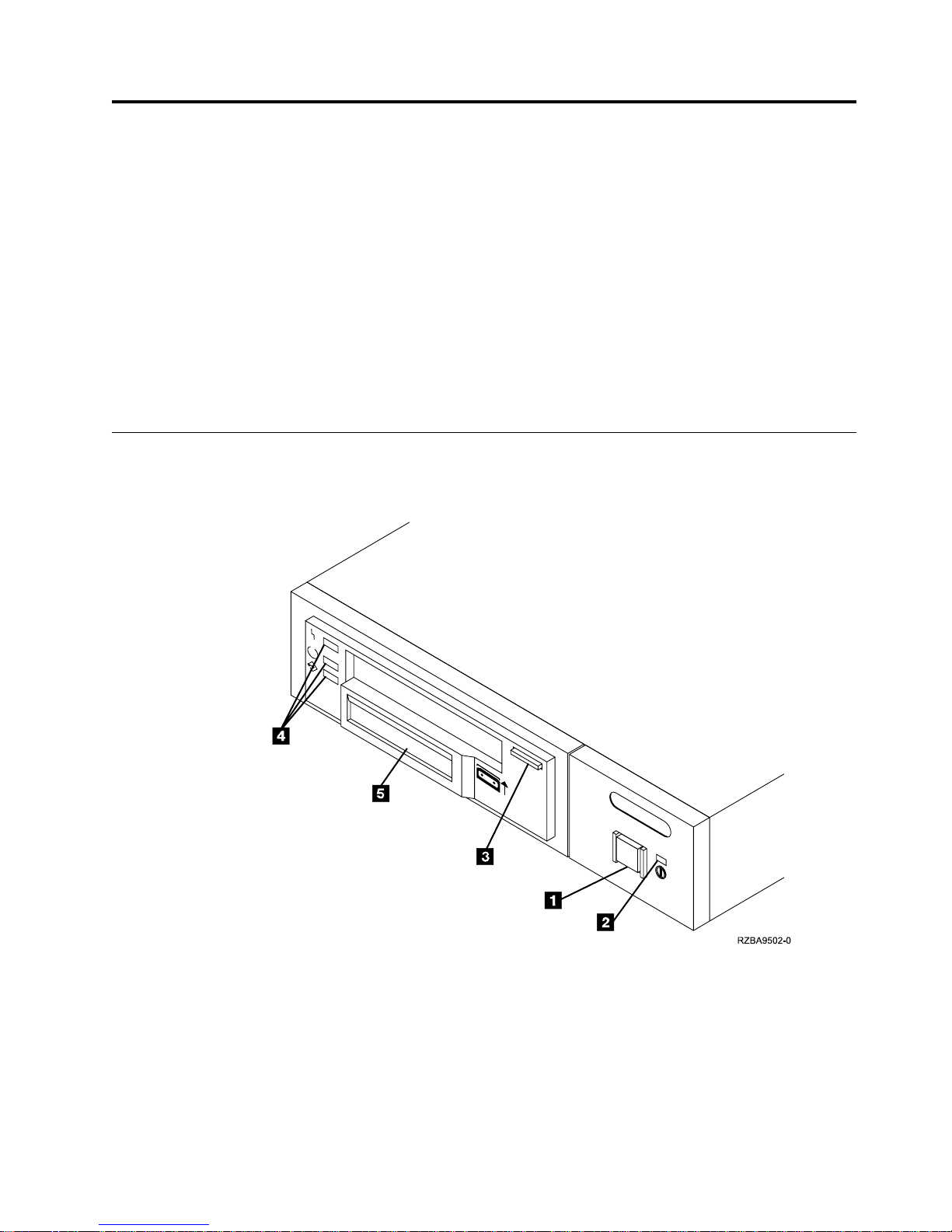
Figure 1 shows the front view of the 7208 Model 345 Tape Drive.
Figure 1. Front View of the 7208 Model 345 Tape Drive
© Copyright IBM Corp. 2000 1
Page 16
Operator Controls
The 7208 Tape Drive has the following operator controls.
Power Switch
The power switch (1 in Figure 1 on page 1) is a push button switch that enables
the power to be turned on or off. When the 7208 Tape Drive is on, the power-on
light 2 is on.
Note: The
Standardization (ISO) symbol for a push button switch.
Unload Button
The unload button 3 enables a tape cartridge to be ejected. The unload button
operates only when the 7208 Tape Drive power is on. To remove a tape cartridge,
press and hold the unload button for about one second.
Indicator Lights
The 7208 Model 345 Tape Drive has the following indicator lights.
Power-On Light
When the 7208 Tape Drive is turned on, the power-on light 2 comes on and stays
on.
Status Lights
Three status lights 4 and their ISO symbols appear on the 7208 Tape Drive as
follows:
The combinations of the lights and their definitions are shown in Table 1.
symbol beside the power switch is an International Organization for
Table 1. Status Lights on the 7208 Tape Drive
Status Lights Status Status of 7208 Tape Drive
2 7208 Model 345 Service Guide
Fault On
Ready
Activity On
Fault
Ready
Activity
On
OfforOn
Off
Off
The Power-On Self Test (POST) is running.
One of the following conditions exists:
v The power is off (Fault light is off).
v The POST has completed successfully, but
no tape cartridge has been inserted. If the
Fault light is on, cleaning is required. See
“Cleaning the Tape Drive” on page 8.
Page 17

Table 1. Status Lights on the 7208 Tape Drive (continued)
Status Lights Status Status of 7208 Tape Drive
Fault
Ready
OfforOn
Off
A tape cartridge has been inserted:
v The 7208 Tape Drive is ready to receive
commands from the system (whether the
Fault light is on or off).
v If the Fault light is on, cleaning is
required. See “Cleaning the Tape Drive”
on page 8.
Activity
Flashing or Off
v If the Activity light flashes, a tape
cartridge is in the drive and tape
movement is occurring. If the light is off,
no tape movement is occurring.
Fault
Ready
Activity
Fault
Ready
Activity
Flashing
OfforOn
Off, On, or Flashing
On
OfforOn
Flashing or Off
The 7208 Tape Drive has detected an
internal fault that requires corrective action:
v Reset the error by turning the power off
to the 7208 Tape Drive, then turning it
back on, or by holding down the unload
button for about 15 seconds.
v If the Fault light still flashes after the
reset, contact your service representative.
The tape drive requires cleaning. See
“Cleaning the Tape Drive” on page 8.
v If the Ready light is on, a tape cartridge
is in the drive. If the light is off, a
cartridge is not in the drive.
v If the Activity light flashes, a tape
cartridge is in the drive and tape
movement is occurring. If the light is off,
no tape movement is occurring.
Chapter 1. Reference Information 3
Page 18

Liquid Crystal Display
The 7208 Tape Drive features a liquid crystal display (LCD) (5 in Figure 1 on
page 1). The LCD provides operating and error messages.
Table 2 shows a list of messages that display on the LCD.
Table 2. LCD Messages
Reset Messages
RESET The first message to appear during the power-on sequence.
MODEL:
SUBMOD: The submodel number of the tape drive.
SN: The serial number of the tape drive.
CODE: The level of the tape drive’s firmware.
LAST CLN: The number of hours since the last cleaning.
COMPRESSION:
SINGLE ENDED or
DIFFERENTIAL
WIDE The width of the SCSI bus (measured in bits or bytes).
SCSI ID:
LANGUAGE:
Tape Drive Status Messages
READY-NOTAPE The tape drive is ready to accept a cartridge.
V‾V LOADING.... The tape drive is loading the tape.
V‾V READY-TAPE The tape drive successfully loaded the tape and is ready for
V‾V ILLEGAL TAPE An unsuitable tape has been loaded and rejected.
<< EJECT======
V‾V EJECT PREVNT
Tape Motion Messages
V↑V READ+uuuuu=
V↓V WRITE+uuuu=
V/V PROTECTED
V/V ILLEGAL WRT
Variable information about the tape drive, in this case
IBM-60GB.
Whether data compression is turned on (the default) or
turned off.
The type of SCSI input/output electrical interface.
The SCSI address of the tape drive (0 through 15). The
default is 0.
The current language used on the LCD. To change the
language, turn off the power to the tape drive. Press and
hold the unload button immediately after turning the
power back on. When the desired language displays, release
the unload button.
read or write operations.
The unload button was pressed. The tape drive will eject
the cartridge as soon as it finishes the current operation.
The unload button was pressed, and the system software
has issued a command to prevent the eject function.
The tape drive is reading data. The + sign appears when
the data is compressed. The boxes (u) represent the amount
of tape processed (out of a total of six boxes). The = sign
represents the amount of unprocessed tape.
The tape drive is writing data. The + sign appears when the
data is compressed.
The tape drive cannot write data because the data cartridge
is write-protected.
The tape drive cannot write to the type of data cartridge
inserted. This message remains until a proper tape is
inserted or a tape motion command is issued.
4 7208 Model 345 Service Guide
Page 19
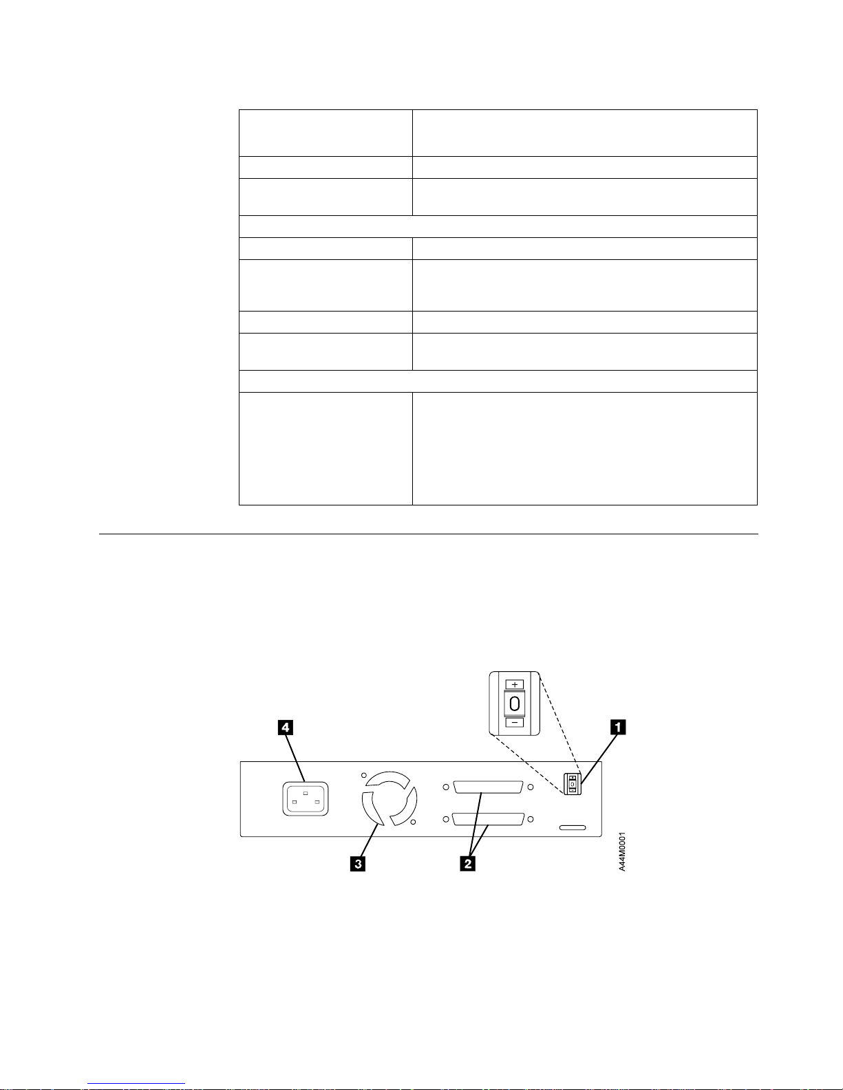
Table 2. LCD Messages (continued)
>> SEARCHuu====
<< SEARCHuu====
<< REWINDuuu=== The rewind function is in progress.
V×V ERASEu=====
Cleaning Messages
V))V CLEAN SOON The tape drive needs to be cleaned.
V))V MUST CLEAN
V))V CLEANING Cleaning is in progress.
V))V DEPLETED
Error Conditions
LAST 3 ERRORS
ERR 1: xx yy zz
ERR 2: xx yy zz
ERR 3: xx yy zz
A high-speed search is in progress.
The tape drive is erasing data on the tape. As the data is
erased, the equal signs (=) change to boxes (u).
The tape drive must be cleaned when advanced
metal-evaporated (AME) media is inserted after using metal
particle (MP) media.
The cleaning tape in the cartridge is used up and the tape
drive will eject it. Insert a new cleaning cartridge.
A hardware error has occurred. The LCD displays the last
three error codes, with ERR 1: xx yy zz as the most
recent. xx = the fault symptom code (FSC). yy and zz =
additional information for product support personnel (the
information may or may not be present). To resolve the
error, refer to “Appendix B. Fault Symptom Codes and
Error Recovery Procedure Numbers” on page 41.
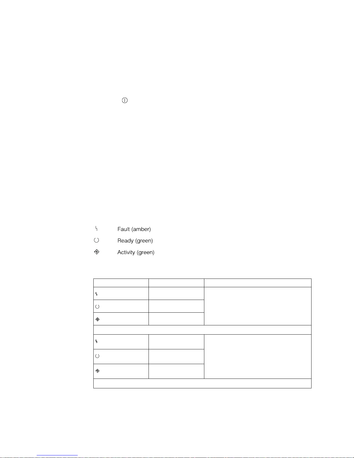
Rear View
Figure 2 shows the connector locations on the 7208 Model 345 Tape Drive:
1 SCSI address switch 3 Fan
2 SCSI bus cable connectors 4 Power cable connector
Figure 2. Rear View of the 7208 Model 345 Tape Drive
Chapter 1. Reference Information 5
Page 20
Rear View of the Drive
Figure 3 shows the connector locations on the drive:
1 Internal SCSI bus connector 3 Internal SCSI address connector
2 Power supply connector
Figure 3. Connector Locations on the Drive
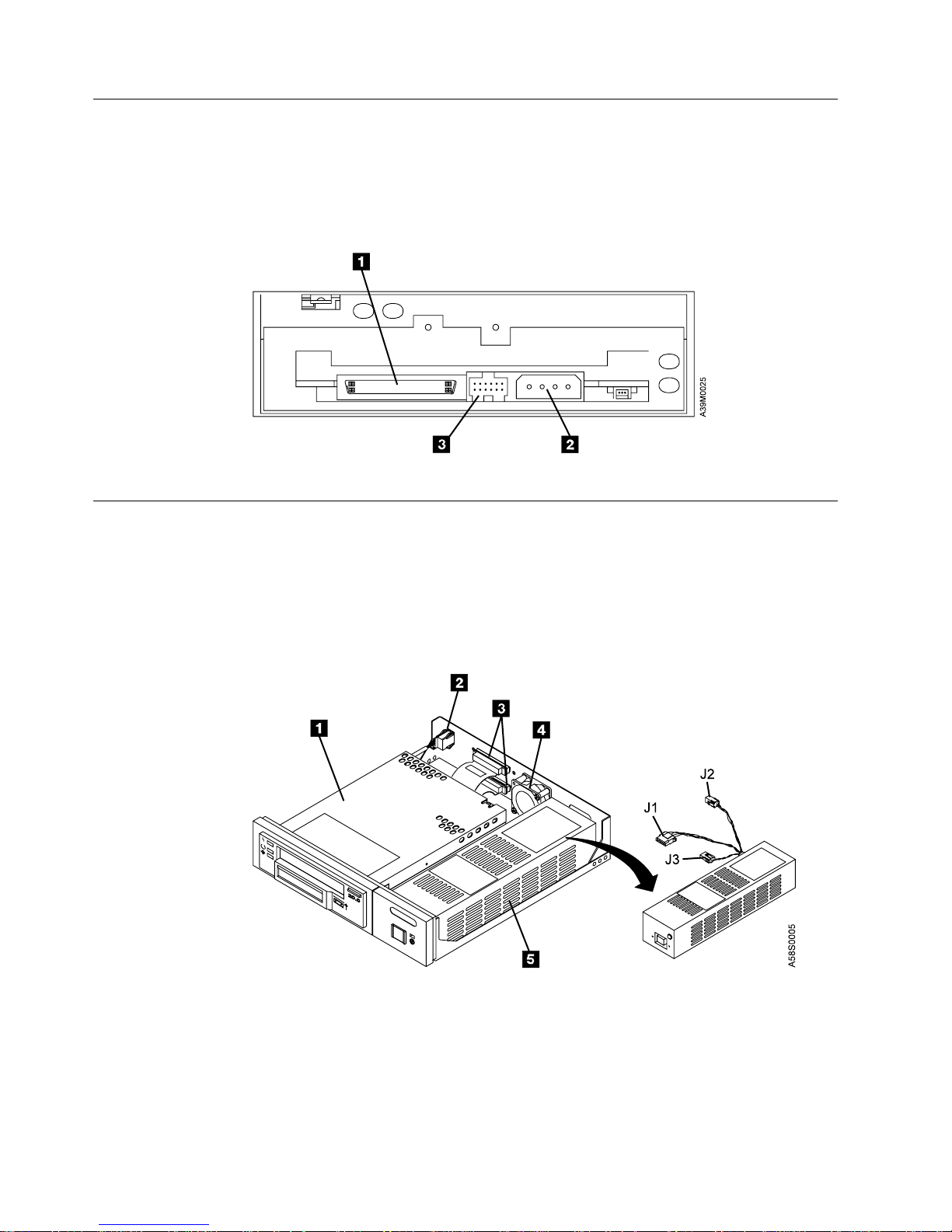
Internal View
Figure 4 shows the inside of the 7208 Model 345 Tape Drive:
1 Drive 4 Cooling fan
2 SCSI address cable 5 Power supply
3 SCSI bus connectors
Figure 4. Internal View of the 7208 Model 345 Tape Drive
6 7208 Model 345 Service Guide
Page 21

Specifications
Table 3. Specifications for the 7208 Model 345 Tape Drive
Physical Specifications
Width 250 mm (9.8 in.)
Depth 275 mm (10.8 in.)
Height 55 mm (2.2 in.)
Weight 3.2 kg (7.1 lb)
Power Specifications
kVA 0.023 @ 120 V ac
V ac 100 to 125, or 200 to 240
Hertz 50 to 60
Btu Maximum (watts) 41.6 Btu/hr (12.2 watts) @ 240 V ac
Power Factor 0.4 to 0.6
Other Specifications
Altitude 2135 m (7000 ft)
Recommended Environment
Environmental Factor Operating Non-operating
Temperature
16 to 32°C
(60 to 90°F)
Relative Humidity
20 to 80% 20 to 95%
(noncondensing)
23°C
Maximum Wet Bulb
(73°F)
Note: The operating limits include media. The storage and shipping limits do not include
media. For media storage and shipping limits, see “Storage and Shipping Environments”
on page 13.
1to60°C
(34 to 140°F)
27°C
(81°F)
Chapter 1. Reference Information 7
Page 22

Cleaning the Tape Drive
Clean the 7208 Tape Drive when the fault light comes on solid (see Table 1 on
page 2), or when the LCD indicates cleaning is required (see Table 2 on page 4).
Note: If you use AME with SmartClean cartridges exclusively, the IBM M2 tape
drive automatically performs the cleaning operation using the cleaning
material in the cartridges. If you do not use SmartClean cartridges
exclusively, the drive may require regular cleaning with an IBM AME 8mm
cleaning cartridge.
The 7208 Tape Drive counts the number of hours of tape motion and indicates
when it is time to clean the tape drive by displaying the message CLEAN SOON and
turning on the Fault status light.
To clean the tape drive, use only the IBM AME 8mm Cleaning Cartridge (part
number 35L1409). For uninterrupted operation, have one or more spare cleaning
cartridges available.
Attention: Do not operate the 7208 Model 345 Tape Drive in a poor air-quality
environment. If your environment contains an excessive amount of particulates,
they may permanently damage the media, the drive, or both. Contact your service
representative for more information.
To load the cleaning cartridge:
1. Make sure that the 7208 Tape Drive power is on and the Power-On Self Test
has completed.
2. Grasp the cleaning cartridge (1 in Figure 5) by the outer edges, with the
window side up and the write-protect switch 2 facing you.
Figure 5. Loading the Cleaning Cartridge
8 7208 Model 345 Service Guide
Page 23

3. Slide the cartridge into the opening on the front of the 7208 Tape Drive until
the loading mechanism pulls the cartridge into the drive and the drive door
closes.
After the cleaning cartridge has been fully inserted into the 7208 Tape Drive, the
remainder of the cleaning process is automatic. The 7208 Tape Drive:
1. Loads the cleaning tape into the tape drive
2. Turns on the Fault status light (if the light is off)
3. Cleans the drive by moving the cleaning tape forward for approximately two
minutes (the Fault status light comes on and the message CLEANING displays)
4. Unloads and ejects the cleaning tape when the cleaning operation is complete
5. Indicates a successful cleaning operation by turning off the Fault status light
The cleaning cartridge can be used for a maximum of 18 cleaning operations. If
you attempt to use the depleted cartridge, the 7208 Tape Drive automatically
detects the error, ejects the cartridge, and displays the message DEPLETED. The Fault
status light remains on to indicate that cleaning is still required. Replace the
depleted cartridge with a new cleaning cartridge.
Chapter 1. Reference Information 9
Page 24

10 7208 Model 345 Service Guide
Page 25

Chapter 2. Using the Media
Use only IBM 8mm cartridges with the 7208 Tape Drive.
Types of 8mm Cartridges
The 7208 Model 345 Tape Drive is shipped with an advanced metal-evaporated
(AME) SmartClean data cartridge, an AME test cartridge, and a cleaning cartridge.
The 7208 Tape Drive reads and writes to new Advanced Metal Evaporated (AME)
data cartridges with SmartClean technology. SmartClean cartridges are designed to
combine the extremely reliable AME recording media with a short segment of tape
drive head cleaning material. The new SmartClean cartridges are easily identified
by their cobalt-blue color and are available from in 75m, 150m, and 225m lengths.
Although extensive use is not recommended, M2 can write to AME cartridges
designed for the first-generation MammothTape technology tape drives. When
these cartridges are used, M2 requires regularly scheduled manual cleaning using a
MammothTape cleaning cartridge. Such maintenance is greatly reduced by using
only SmartClean media in M2.
Data Cartridge
Use the AME data cartridge for saving or restoring your programs or data.
Large and small labels are shipped with the data cartridge. To avoid problems with
loading and unloading a tape, use only the small label on the tape cartridge and
place the label in location 1 shown in Figure 6. Place the large label on the
cartridge container.
Figure 6. Placement of Label on an 8mm Data Cartridge
© Copyright IBM Corp. 2000 11
Page 26

Test Cartridge
Use the specially labeled test cartridge to perform diagnostics on the drive. Do not
use it to save or restore programs or data.
Cleaning Cartridge
Use the specially labeled cleaning cartridge to clean the tape drive (see “Cleaning
the Tape Drive” on page 8).
To order additional cartridges, refer to “Ordering Tape Cartridges” on page 15.
Guidelines for Using Tape Cartridges
Observe the following guidelines for using media with the 7208 Model 345 Tape
Drive:
Attention: Do not use video-grade cartridges, as they are hazardous to the 7208
Tape Drive and will void your warranty.
Before using a cartridge, let it acclimate to the operating environment for as long
as it has been away from the environment or for 24 hours, whichever is less.
Use only IBM 8mm cartridges with the 7208 Model 345 Tape Drive. IBM only
supports the use of IBM media. To order tape cartridges, see “Ordering Tape
Cartridges” on page 15.
Attention: Clean the 7208 Tape Drive:
v Whenever you replace a worn tape
v Whenever you replace a defective tape
v Whenever the CLEANING message displays
For more information, see “Cleaning the Tape Drive” on page 8.
Do not write to previously written software distribution tapes. Often these tapes
will not support being rewritten without modifications to the cartridge. If the
cartridge is modified, it is possible to cause tape jams or tape misalignment.
Back up and then discard any tape that repeatedly produces error messages. (The
error information is in the System Error Log.)
Do not open the door that covers the tape in the data cartridge. This door protects
the magnetic tape from dirt, dust, and damage.
Do not touch the tape material. Any substance transferred to the tape by touching
could cause loss of data.
Do not operate the 7208 Tape Drive in a dusty environment.
Do not store tape cartridges or the 7208 Tape Drive in a dusty environment.
Do not store tape cartridges flat. Store tape cartridges vertically on the long narrow
spine in their protective case.
12 7208 Model 345 Service Guide
Page 27

Storage and Shipping Environments
Before using an 8mm tape cartridge, let it acclimate by placing the cartridge in the
operating environment for as long as it has been away from the environment, or
for 24 hours, whichever is less.
Acclimation is necessary for any data cartridge that has been exposed to a different
humidity environment or to temperature changes of 11°C (20°F) or more.
The 8mm data cartridge can be stored and shipped in a wide variety of
environments. Table 4 provides a description of these environments.
Table 4. Recommended Environment for 8mm Data Cartridges
Environmental Factor Storage Shipping
Temperature
Relative Humidity
(noncondensing)
Maximum Wet Bulb
Operating in Harsh Environments
The 7208 Tape Drive is ideally suited to streaming operations, as opposed to
multiple stop-and-start, random-search tape operations. When the tape is used for
frequent stop-and-start operations, it is beneficial to still have as much streaming
movement as possible. This can be accomplished by ensuring that any save or
restore operation is the only active operation being performed.
Do not use as an archival tape any tape that has been used outside of the ranges
specified in Table 4 for an extended period of time. The magnetic and physical
strength of the tape will have deteriorated as a result of its exposure to the
environment. Do not store important data on such a tape; transfer the data to a
newer tape for reliable archiving.
5to32°C
(41 to 90°F)
20 to 80% 20 to 80%
26°C
(79°F)
−40 to 45°C
(−40 to 113°F)
26°C
(79°F)
Chapter 2. Media 13
Page 28

Setting the Write-Protect Switch
The position of the write-protect switch on the 8mm tape cartridge determines
when you can write to the tape.
v When the switch is set to the left in the SAVE position 1, data cannot be written
to or read from the tape (data is saved).
v When the switch is set to the right in the REC (Record) position 2, data can be
written to and read from the tape.
Figure 7. Setting the Write-Protect Switch
14 7208 Model 345 Service Guide
Page 29

Ordering Tape Cartridges
Table 5 lists the tape cartridges that you can order for the 7208 Model 345 Tape
Drive. To order cartridges in the United States and Canada, call 1-888-IBM-MEDIA.
To order cartridges in other locations, contact your local provider of IBM storage
products.
Table 5. Tape Cartridges for the 7208 Model 345 Tape Drive
IBM Part Number Type of Cartridge Length
35L1044
09L5323
09L5322
35L1409 8mm Cleaning Cartridge ––
20 GB 8mm AME with SmartClean
Data Cartridge
40 GB 8mm AME with SmartClean
Data Cartridge
60 GB 8mm AME with SmartClean
Data Cartridge
75 m (246 ft)
150 m (492 ft)
225 m (738 ft)
Chapter 2. Media 15
Page 30

16 7208 Model 345 Service Guide
Page 31

Chapter 3. Maintenance Analysis Procedures
DANGER
To prevent a possible electrical shock from touching two surfaces with
different electrical grounds, use one hand, when possible, to connect or
disconnect signal cables. (RSFTD004)
DANGER
An electrical outlet that is not correctly wired could place hazardous voltage
on metal parts of the system or the products that attach to the system. It is the
customer’s responsibility to ensure that the outlet is correctly wired and
grounded to prevent an electrical shock. (RSFTD201)
Purpose of the MAPs
Maintenance analysis procedures (MAPs) are used to check the:
Power cable Configuration SCSI bus (signal) cable
Power supply Drive SCSI address
Terminator Fan
Media Drive head
If a problem is detected, the procedure isolates the problem to the failing field
replaceable unit (FRU), such as the 7208 Tape Drive cover, drive, power supply, or
cooling fan.
For instructions about removing or replacing a FRU, refer to “Chapter 4. Removal
and Replacement Procedures” on page 25.
Figure 8 on page 18 provides a flowchart to be used as a guide to the MAPs. For
detailed instructions on how to perform each procedure safely and correctly, refer
to the steps in this chapter.
© Copyright IBM Corp. 2000 17
Page 32

Flowchart of the MAPs
Figure 8. Flowchart of the Maintenance Analysis Procedures (MAPs)
18 7208 Model 345 Service Guide
Page 33

Step 1
Step 2
This step verifies whether the 7208 Tape Drive is receiving electrical power and the
fan is operating properly.
1. Make sure that the 7208 Tape Drive power cable is plugged into an electrical
outlet.
2. Make sure that the 7208 Tape Drive power is on by checking that:
v The power-on light is on.
v There is airflow from the fan at the rear of the unit.
Is the power-on light on and is there airflow from the fan?
NO While watching for the power-on light to come on, press the power switch
again. Repeat this procedure several times. If the power-on light fails to
come on or if there is no airflow from the fan, go to Step 2.
YES Go to Step 8.
This step tests the voltage at the electrical outlet.
1. Do a controlled system shutdown (refer to the instructions in Chapter 2,
“Setting Up the 7208 Tape Drive,” in the 7208 Model 345 8mm Tape Drive Setup
and Operator Guide).
2. Ensure that the power to the host system is off.
3. Press the 7208 Tape Drive power switch to turn off the power.
4. Unplug the 7208 Tape Drive power cable from the electrical outlet and from the
7208 Tape Drive.
5. Measure the voltage at the electrical outlet.
Step 3
Is the voltage from the electrical outlet correct?
NO Contact your service personnel for further instructions.
YES Go to Step 3.
This step determines whether the power cable is functional.
Make sure that all of the conductors in the power cable have continuity, and that
there are no short circuits.
Does the power cable have continuity and are there no short circuits?
NO Replace the power cable, then go to Step 1.
YES Go to Step 4.
Chapter 3. Maintenance Analysis Procedures 19
Page 34

Step 4
Step 5
This step prepares the 7208 Tape Drive to determine whether the power supply,
fan, or tape drive is the cause of the problem.
1. Remove the cover of the 7208 Tape Drive. Refer to “Removing and Replacing
the Cover” on page 26.
2. Disconnect the power supply connector (J1) from the drive.
3. Disconnect the power supply connector (J2) between the power supply and the
cooling fan.
4. Plug the 7208 Tape Drive power cable into the 7208 Tape Drive and into a
grounded electrical outlet.
5. Press the 7208 Tape Drive power switch to turn on the power.
Does the power-on light come on and stay on?
NO Replace the power supply, then go to Step 5. Refer to “Removing and
Replacing the Power Supply” on page 28.
YES Go to Step 5.
This step checks the power supply voltage levels as the possible source of the
problem.
1. Press the power switch to turn off the power.
2. Disconnect the power supply connector (J1) from the drive.
3. Disconnect the power supply connector (J2) between the power supply and the
cooling fan.
4. Connect the power cable to both the 7208 Tape Drive and to the electrical
outlet.
5. Press the power switch to turn on the power.
6. On the power supply connector J1 (see Figure 9), check the following:
v The +12V signal falls between a minimum of +11.5 volts and a maximum of
+12.6 volts
v The +5V signal falls between a minimum of +4.8 volts and a maximum of
+5.25 volts
Figure 9. Power Supply Connector J1
20 7208 Model 345 Service Guide
Page 35

Step 6
7. On the power supply connector J2 (see Figure 10), check that the +12V signal
falls between a minimum of +11.5 volts and a maximum of +12.6 volts.
Figure 10. Power Supply Connector J2
Are the voltages good, and does the power-on light come on and stay on?
NO Replace the power supply, and then return to Step 4. Refer to “Removing
and Replacing the Power Supply” on page 28.
YES Go to Step 6.
This step examines the cooling fan as the possible source of the problem.
1. Press the power switch to turn off the power.
2. Reconnect the power supply connector (J2) to the cooling fan.
3. Press the power switch to turn on the power.
Step 7
Does the power-on light come on and stay on, and is there airflow from the fan?
NO Replace the cooling fan, then return to Step 6. Refer to “Removing and
Replacing the Cooling Fan” on page 30.
YES Go to Step 7.
This step examines the drive as the possible source of the problem.
1. Press the power switch to turn off the power.
2. Reconnect the power supply connector (J2) to the drive.
3. Press the power switch to turn on the power.
Does the power-on light come on and stay on, and is there airflow from the fan?
NO Replace the drive, then return to Step 7. Refer to “Removing and Replacing
the Drive” on page 27.
YES Go to Step 8.
Chapter 3. Maintenance Analysis Procedures 21
Page 36

Step 8
Step 9
This step examines the drive as the possible source of the problem.
While pressing the power switch to turn on the power, watch for the following:
v The three status lights come on for approximately 10 seconds, then go out.
v The LCD displays the message READY-NOTAPE or READY-TAPE.
Did the three status lights come on and go out, and did the message
READY-NOTAPE or READY-TAPE display?
NO Refer to “Appendix B. Fault Symptom Codes and Error Recovery
Procedure Numbers” on page 41 and follow the problem determination
steps.
YES Go to Step 9.
This step checks whether the SCSI address switch setting is correct.
Is the SCSI address set correctly?
NO Set the SCSI address to the correct setting, then return to Step 1. Refer to
the instructions for setting the SCSI address in the 7208 Model 345 8mm
Tape Drive Setup and Operator Guide.
Step 10
Step 11
YES Go to Step 10.
This step examines the tape cartridge as the possible source of the problem.
1. If there is a tape cartridge currently in the drive, press the unload button to
eject it. If the cartridge fails to eject, refer to “Manually Removing a Tape
Cartridge” on page 31.
2. With the power turned on to the 7208 Tape Drive, insert a blank IBM AME
data cartridge.
3. Check that after approximately 20 seconds, the Ready light comes on and stays
on, and the LCD displays the message READY-TAPE.
Did the cartridge load correctly?
NO Refer to “Appendix B. Fault Symptom Codes and Error Recovery
Procedure Numbers” on page 41 and follow the problem determination
steps.
YES Go to Step 11.
This step describes the reassembly process.
1. Press the power switch to turn off the power.
2. Unplug the power cable from the electrical outlet.
3. Make sure that the power supply connector (J1) is plugged into the drive.
4. Make sure that the power supply connector (J2) is plugged into the cooling fan.
22 7208 Model 345 Service Guide
Page 37

Step 12
5. Make sure that all other cables are properly connected, and that the wires are
routed away from the cooling fan.
6. Perform the cover replacement procedure. Refer to “Removing and Replacing
the Cover” on page 26.
7. Plug the power cable into the electrical outlet.
8. Press the power switch to turn on the power.
Does the power-on light come and stay on, and is there airflow from the fan?
NO Verify that the 7208 Tape Drive was reassembled correctly. If the power-on
light still does not come on and there is no airflow from the fan, go to Step
1.
YES Go to Step 12.
This step ensures that the external SCSI bus cable connection is proper.
Ensure that the SCSI bus cable is properly connected to both the host system and
to the 7208 Tape Drive.
Is the SCSI bus cable properly connected to the host system and to the 7208
Tape Drive?
Step 13
NO Plug the SCSI bus cable into both the host system and the 7208 Tape Drive,
then go to Step 13.
YES Go to Step 13.
This step ensures that the terminator is properly connected.
Ensure that the correct LVD terminator is used and properly connected to the last
device on the SCSI bus.
Is the correct LVD terminator properly connected to the last device on the SCSI
bus?
NO Ensure that the terminator is properly connected to the last device on the
SCSI bus, then go to Step 14.
YES Go to Step 14.
Chapter 3. Maintenance Analysis Procedures 23
Page 38

Step 14
Step 15
Step 16
This step verifies that the 7208 Tape Drive is properly configured to the host
system. Refer to your system manuals and the 7208 Model 345 8mm Tape Drive
Setup and Operator Guide to determine whether the 7208 Tape Drive is properly
configured.
Does the 7208 Tape Drive that you are configuring appear under the Description
column, and can it be powered off and on successfully?
NO Go to Step 15.
YES Go to Step 16.
This step verifies whether the 7208 Tape Drive can communicate with the host
system. Refer to your system manuals for instructions about determining if the
host system is communicating with the 7208 Tape Drive.
Are the 7208 Tape Drive and the host system communicating?
NO Contact your service personnel for further instructions.
YES Go to Step 16.
This step runs the AIX diagnostics.
Run the diagnostics on the 7208 Tape Drive. Have the test cartridge available for
when the diagnostics prompt you to load the cartridge. From the AIX command
prompt, type:
diag
and then press Enter. For additional instructions on running diagnostics, refer to
your AIX manuals.
Do all of the diagnostics routines pass?
NO Replace the FRU isolated by the diagnostics and identified by the service
request number.
Note: If the drive is the FRU isolated by the diagnostics, check that the J1
connector is properly seated. If the drive has recently been replaced
because of a similar problem, contact your service personnel.
YES If no problem was identified, the problem may be intermittent, related to
the tape quality, or relating to the environment. If a FRU was replaced or
changed and no more errors occur, the problem is fixed.
This completes the MAPs.
24 7208 Model 345 Service Guide
Page 39

Chapter 4. Removal and Replacement Procedures
This chapter describes the procedures to follow when removing and replacing the
field replaceable units (FRUs), such as the 7208 Tape Drive cover, drive, power
supply, and cooling fan. It also describes how to manually remove a tape cartridge.
DANGER
To prevent a possible electrical shock from touching two surfaces with
different electrical grounds, use one hand, when possible, to connect or
disconnect signal cables. (RSFTD004)
DANGER
To prevent a possible electrical shock when adding or removing any devices
to or from the system, ensure that the power cords for those devices are
unplugged before the signal cables are connected or disconnected. If possible,
disconnect all power cords from the existing system before you add or
remove a device. (RSFTD203)
Before installing any FRU, let it acclimate to the operating environment for as long
as it has been away from the environment or for 12 hours, whichever is less.
Handling Static-Sensitive Devices
Attention: Tape drives are sensitive to static electricity discharge. When handling
a tape drive, wrap it in an antistatic bag to prevent damage.
Take the following precautions:
v Do not remove the drive from the antistatic bag until you are ready to install it.
v With the drive still in its antistatic bag, touch it to the metal frame of an
electrically grounded surface.
v Hold the drive by the frame. Avoid touching the solder joints or pins.
v Handle the drive carefully to prevent permanent damage.
© Copyright IBM Corp. 2000 25
Page 40

Removing and Replacing the Cover
To remove the cover from the 7208 Tape Drive:
1. If a tape cartridge is loaded in the drive, eject it.
2. Do a controlled system shutdown (refer to the instructions in Chapter 2,
“Setting up the 7208 Tape Drive,” in the 7208 Model 345 8mm Tape Drive Setup
and Operator Guide).
3. If it is on, turn off the power to the 7208 Tape Drive.
4. Unplug the 7208 Tape Drive power cable from the electrical outlet.
5. Disconnect the power cable from the 7208 Tape Drive.
6. Disconnect the SCSI bus (signal) cable from the 7208 Tape Drive.
7. Tilt the 7208 Tape Drive on its side and remove the four cover mounting screws
from the bottom (see Figure 11).
8. Remove the cover by sliding it to the rear (see the directional arrow in
Figure 11).
To replace the cover, reverse the removal procedure.
Figure 11. Removing and Replacing the Cover
26 7208 Model 345 Service Guide
Page 41

Removing and Replacing the Drive
To remove the drive from the 7208 Tape Drive:
1. Perform the cover removal procedure. Refer to “Removing and Replacing the
Cover” on page 26.
2. Tilt the 7208 Tape Drive on its side. Support the drive (1 in Figure 12) while
removing the four screws 2 that secure the drive to the chassis.
3. Support the drive while returning the 7208 Tape Drive to its original position.
4. Disconnect the power supply connector (J1) 3 from the drive.
5. Disconnect the internal SCSI bus cable 4 from the drive.
Note: To remove the cable, grasp the connector and pull it towards you. Do
not pull on the cable.
6. Disconnect the internal SCSI address cable 5 from the drive.
7. Slide the drive forward and out of the chassis.
Figure 12. Removing and Replacing the Drive
Chapter 4. Removal and Replacement Procedures 27
Page 42

To replace the drive, reverse the removal procedure. Make sure to:
v Correctly insert and engage each cable to its proper connector.
v Arrange the cables so that they do not interfere with the cooling fan blades or
the replacement of the cover.
v After installing the cover, align the drive with the front of the cover, then tighten
the four screws (2 in Figure 12 on page 27) that secure the drive to the chassis.
Note: The power supply connector J3 is not used in the 7208 Model 345 Tape
Drive.
Removing and Replacing the Power Supply
DANGER
Do not attempt to open the covers of the power supply. Power supplies are
not serviceable and are to be replaced as a unit. (RSFTD217)
To remove the power supply from the 7208 Tape Drive:
1. Perform the cover removal procedure. Refer to “Removing and Replacing the
Cover” on page 26.
2. Tilt the 7208 Tape Drive (1 in Figure 13 on page 29) on its side. Support the
power supply while removing the power supply mounting screw 2 from the
bottom.
3. Support the power supply while returning the 7208 Tape Drive to its original
position.
4. Disconnect the power supply connector (J1) 3 from the drive.
5. Disconnect the power supply connector (J2) 4 between the power supply and
the cooling fan.
6. Grasp the rear of the power supply 5 and while pressing it toward the front
panel, lift the rear of the power supply, then remove it from the chassis.
7. Push the power switch push button 6 out of the front panel and set it aside.
8. Remove the electromagnetic interference (EMI) gasket 7 and save it for
installation with the replacement power supply.
28 7208 Model 345 Service Guide
Page 43

Figure 13. Removing and Replacing the Power Supply
To replace the power supply, reverse the removal procedure. Make sure to:
v Align the power supply on the base of the chassis and inside the two tabs (8
in Figure 13).
v Insert the EMI gasket 7 between the power supply and the drive.
v To reduce radiated noise, perform five full (360°) twists of the J1 power cable
3.
v With its locking features in a horizontal position, insert the power switch push
button 6 into the front panel and press until it locks in place.
Note: If the power switch does not work properly, loosen the power supply
mounting screw 2, slide the power supply to the rear of the chassis, and
retighten the mounting screw.
v Arrange the cables so that they do not interfere with the cooling fan blades or
the replacement of the cover. Ensure that they do not obstruct airflow through
the fan.
Note: The power supply connector J3 is not used in the 7208 Tape Drive.
Chapter 4. Removal and Replacement Procedures 29
Page 44

Removing and Replacing the Cooling Fan
To remove the cooling fan:
1. Perform the cover removal procedure. Refer to “Removing and Replacing the
Cover” on page 26.
2. Disconnect the power supply connector (J2) (1 in Figure 14) between the
power supply and the cooling fan.
3. Remove the two screws, lockwashers, and nuts 2 that secure the cooling fan
to the rear of the 7208 Tape Drive.
4. Lift the cooling fan out of the 7208 Tape Drive.
To replace the cooling fan, reverse the removal procedure. Make sure that the
cooling fan is oriented so that air flows out from the rear of the 7208 Tape Drive.
Figure 14. Removing and Replacing the Cooling Fan
30 7208 Model 345 Service Guide
Page 45

Manually Removing a Tape Cartridge
If a power failure or a drive failure prevents the tape cartridge from ejecting, the
cartridge can be removed manually.
Before manually removing the tape cartridge, turn off the 7208 Tape Drive, then
turn it on again to clear potential error conditions. Press the unload button. If the
tape does not eject, proceed with the manual removal.
Attention: The procedure that follows may result in damage to your tape
cartridge. If you use this procedure, you must replace the drive. If you choose to
return the drive and the stuck tape to IBM for maintenance, the tape will be
scrapped.
To manually remove a tape cartridge:
1. Perform the cover removal procedure. Refer to “Removing and Replacing the
Cover” on page 26.
2. Perform the drive removal procedure. Refer to “Removing and Replacing the
Drive” on page 27.
3. Using a Torx screwdriver, remove the three T-6 screws that secure the top
cover of the drive (one on the rear and two sides of the drive). See Figure 15.
Figure 15. Removing the Top Cover of the Drive
4. Slide the cover to the rear of the drive and remove it completely.
5. If it obvious that the tape must be destroyed before it can be removed,
perform the following procedure. Otherwise, go to step 6 on page 32.
Attention: This procedure will destroy the tape cartridge and its data. Use
the following procedure only if the loaded tape is known to be damaged or
cannot be unloaded by another method.
a. Cut the tape at a convenient location.
b. Manually unload the tape cartridge (see step 9 on page 34).
Chapter 4. Removal and Replacement Procedures 31
Page 46

6. Position the drive so that it faces you.
7. Take up slack in the tape by using the following instructions to move the
drive’s trolleys and the supply reel motor.
Attention: To avoid damaging the tape, do not touch it.
v To move the drive’s trolleys:
a. On the left side panel of the drive (toward the rear) locate the hole
marked UNLOAD (1 in Figure 16).
b. Insert a 2.5-mm L-Hex (allen) wrench approximately 43 mm (2 in.) into
the UNLOAD hole. Position it so that it seats securely into the inner socket.
c. Turn the wrench in the direction marked on the drive (clockwise).
d. Rotate the wrench until the trolleys 2 stop moving. This may take
more than 120 turns of the wrench.
Figure 16. Moving the Trolleys
32 7208 Model 345 Service Guide
Page 47

v To move the supply reel motor:
a. On the bottom of the drive, locate the hole marked UNLOAD (1 in
Figure 17) and cut the seal above the hole.
b. Insert a non-metallic probe (such as the wooden end of a swab)
approximately 0.64 cm (0.25 in.) into the UNLOAD hole and position it so
that it rests on the inner flange 2.
c. Gently push the flange with the probe in the direction marked on the
drive (clockwise).
d. Repeat the preceding step until there is no slack in the tape. This may
take many motions to retract all of the tape. Perform this motion until
you feel a definite tightening in the flange tension.
Figure 17. Moving the Supply Reel Motor. The drive is turned upside down.
8. Ensure that the tape is fully retracted into the cartridge.
Chapter 4. Removal and Replacement Procedures 33
Page 48

9. Unload the tape cartridge by doing the following:
a. At the left front of the drive, insert a 2.5-mm L-Hex wrench into the hole
marked UNLOAD (1 in Figure 18).
b. Turn the wrench in the direction marked on the drive (counterclockwise)
until the tape ejects.
Figure 18. Unloading the Tape Cartridge
10. Replace the cover of the drive (reverse the removal procedure).
11. Replace the drive (refer to “Removing and Replacing the Drive” on page 27).
Note: Service personnel should record on the service action report the error
message that displayed on the LCD and the fact that the tape cartridge had
to be manually removed.
34 7208 Model 345 Service Guide
Page 49

Chapter 5. Parts Diagram and Parts List
This chapter provides the parts diagram and parts list required to service the 7208
Model 345 Tape Drive.
How To Use This Parts List
AR (As Required) in the Units column indicates that the quantity is not
the same for all machines.
NP (Non-Procurable) in the Part Number column indicates that the part
is non-procurable and that the individual parts or the next higher
assembly should be ordered.
NR (Not Recommended) in the Units column indicates that the part is
procurable but not recommended for field replacement, and that
the next higher assembly should be ordered.
00 (Not Shown) in the Asm- Index column indicates that the part is
either not shown or not referenced in the illustration.
R (Restricted) in the Units column indicates that the part has a
restricted availability.
Indenture The indenture is marked by a series of dots located before the
parts description. The indenture indicates the relationship of a part
to the next higher assembly. For example:
Indenture Relationship of Parts
(No dot) MAIN ASSEMBLY
(One dot) v Detail parts of a main assembly
(One dot) v Sub assembly of the main assembly
(Two dots) vvDetail part of a one-dot sub assembly
(Two dots) vvSub assembly of a one-dot sub assembly
(Three dots) vvvDetail part of a two-dot sub assembly
Example of Parts Listing
AsmIndex
3- 2512667
-1 5373637 1 vSeal, Top
-2 5356429 2 vClip, Retaining
-3 1847630 1 vFinger Stock Asm
-4 1847602 NR vvChannel, Finger Stock
-5 5373639 AR vSeal, Bottom
-6 NP 1 vCover, Rear, Without Paint
Part Number Units Description
2513714
1
1
Cover Asm, Rear, Red
Cover Asm, Rear, White
For Next Higher Asm, see Assembly 1-2.
© Copyright IBM Corp. 2000 35
Page 50

Assembly 1: Parts Diagram
36 7208 Model 345 Service Guide
Page 51

Assembly 1: (continued)
Asm–
Index
1–1 59H3759 1 Power supply
–2 1622401 2 Nut, cooling fan, M3 hex
–3 1622344 2 Washer, cooling fan
–4 42F7300 1 Cooling fan
–5 46G2677 1 Screw, power supply, M3 x 6mm
–6 46G2676 2 Screw, cooling fan, M3 x 25mm
–7 59H2694 1 Cable, SCSI address
–8 46G2677 4 Screw, cover, M3 x 6mm
–9 59H2689 1 Chassis
–10 59H3771 1 Bezel assembly
–11 59H2690 1 Cable, SCSI-2 internal
–12 19P0708 1 Drive (60GB LVD IBM M2)
–13 46G2677 4 Screw, drive
–14 59H3846 1 Cover, includes feet
–15 1622673 2 Screw, bezel
–16 74G8497 1 Push button, power supply
–17 19P0694 1 Logo
–18 19P1434 1 Label, SCSI LVD
–19 71F0734 1 EMI gasket
–00 09L5322 1 Data cartridge, 225 m
–00 09L5323 1 Data cartridge, 150 m
–00 35L1044 1 Data cartridge, 75 m
–00 59H2677 1 Test cartridge (short length for customer engineer use)
–00 35L1409 1 Cleaning cartridge
–00 19P0051 1 Device-to-device SCSI bus cable, 0.5 meter (1.75 feet) HD68 to HD68
–00 19P0279 1 VHDCI/HD68 SCSI cable, 2.5 meter
–00 19P0050 1 VHDCI/HD68 SCSI cable, 4.5 meter
–00 19P0048 1 VHDCI/HD68 SCSI cable, 10 meter
–00 35L0145 1 Terminator, SCSI LVD
Part
Number Units Description
Chapter 5. Parts Diagram and List 37
Page 52

38 7208 Model 345 Service Guide
Page 53

Appendix A. Power Cables
To avoid electrical shock, a power cable with a grounded attachment plug has been
provided. Use only properly grounded outlets.
Power cables used in the United States and Canada are listed by Underwriter’s Laboratories
(UL) and certified by the Canadian Standards Association (CSA). The power cables consist
of:
v Electrical cables, type SVT or SJT.
v Attachment plugs complying with National Electrical Manufacturers Association (NEMA)
5-15P, that is:
“For 115 V operation use a UL Listed Cable Set consisting of a minimum 18 AWG, Type
SVT or SJT three conductor cable a maximum of 15 feet in length and a parallel blade,
grounding type attachment plug rated at 15 A, 125 V.”
“For 230 V operation in the United States use a UL Listed Cable Set consisting of a
minimum 18 AWG, Type SVT or SJT three conductor cable a maximum of 15 feet in
length, and a tandem blade, grounding type attachment plug rated at 15 A, 250 V.”
v Appliance couplers complying with International Electrotechnical Commission (IEC)
Standard 320, Sheet C13.
Power cables used in other countries consist of:
v Electrical cables, type HD21.
v Attachment plugs approved by the appropriate testing organization for the specific
countries where they are used.
“For units set at 230 V (outside of U. S.): Use a Cable Set consisting of a minimum 18
AWG cable and grounding type attachment plug rated 15 A, 250 V. The Cable Set should
have the appropriate safety approvals for the country in which the equipment is to be
installed and marked 'HAR'.”
Table 6 lists the power cable part number, the country where the power cable can be used,
and an index number to be matched with the receptacles shown in Figure 19 on page 40. If
your power cable does not match this information, contact your local dealer.
Table 6. Power Cable Information
Part Number Country Index
1838574 Japan Bahamas, Barbados, Bolivia, Brazil, Canada, Costa
Rica, Dominican Republic, Ecuador, El Salvador,
Guatemala, Guyana, Haiti, Honduras, Jamaica,
Japan, Netherlands Antilles, Panama, Peru,
Philippines, Taiwan, Thailand, Tobago, Trinidad,
U.S.A. (except Chicago), Venezuela
6952300 US/Canada Bahamas, Barbados, Bermuda, Bolivia, Brazil,
Canada, Cayman Islands, Colombia, Costa Rica,
Dominican Republic, Ecuador, El Salvador,
Guatemala, Guyana, Haiti, Honduras, Jamaica,
Japan, Korea (South), Mexico, Netherlands
Antilles, Nicaragua, Panama, Peru, Philippines,
Puerto Rico, Saudi Arabia, Suriname, Taiwan,
Trinidad, U.S.A. (except Chicago), Venezuela
6952301 6 ft Chicago Chicago, U.S.A. 2
13F9940 Australia Argentina, Australia, New Zealand, Uruguay 3
1
2
© Copyright IBM Corp. 2000 39
Page 54

Table 6. Power Cable Information (continued)
Part Number Country Index
13F9979 France Abu Dhabi, Austria, Belgium, Bulgaria, Botswana,
4
Egypt, Finland, France, Germany, Greece, Iceland,
Indonesia, Korea (South), Lebanon, Luxembourg,
Macau, Netherlands, Norway, Portugal, Saudi
Arabia, Spain, Sudan, Sweden, Turkey, Yugoslavia
13F9997 Denmark Denmark 5
14F0015 South Africa Bangladesh, Burma, Pakistan, South Africa, Sri
6
Lanka
14F0033 United
Kingdom
Bahrain, Bermuda, Brunei, Channel Islands,
Cyprus, Ghana, Hong Kong, India, Iraq, Ireland,
7
Jordan, Kenya, Kuwait, Malawi, Malaysia,
Nigeria, Oman, People’s Republic of China, Qatar,
Sierra Leone, Singapore, Tanzania, Uganda,
United Arab Emirates (Dubai), United Kingdom,
Zambia
14F0051 Switzerland Liechtenstein, Switzerland 8
14F0069 Italy Chile, Ethiopia, Italy 9
14F0087 Israel Israel 10
6952291 Colombia Colombia, Paraguay 11
123
56 7 8
910 11
4
26415-00
Figure 19. Types of Receptacles
40 7208 Model 345 Service Guide
Page 55

Appendix B. Fault Symptom Codes and Error Recovery
Procedure Numbers
Use Table 7 to resolve error messages that appear on the LCD of the 7208 Model
345 Tape Drive:
1. Determine the fault symptom code (FSC) in the error message (the first two
digits in the message). For example, in error message ERR 1: AD 58 C0, the
FSC is AD.
2. Locate the FSC in Table 7 and identify the error recovery procedure (ERP)
number for that FSC.
3. Locate the ERP number in Table 8 on page 49, and identify the recommended
error recovery procedure.
Note: Abbreviations in the Description column are defined as follows:
EOD End Of Data
EOT End Of Tape
LBOP Logical Beginning Of Partition
LBOT Logical Beginning Of Tape
LEOP Logical End Of Partition
LEOT Logical End Of Tape
PBOP Physical Beginning Of Partition
PBOT Physical Beginning Of Tape
PEOT Physical End Of Tape
PEOP Physical End Of Partition
Note: Items in the Cause column are defined as follows:
A = Application software O = Operator
B = Bus (SCSI) S = System
D = Drive T = Tape
I = Informational message
Table 7. Fault Symptom Codes (FSC) and Error Recovery Procedure (ERP) Numbers
FSC Description ERP Number Cause
02
03
04
The tape is at an incorrect position to perform a
WRITE operation.
Tape is write protected for the requested WRITE
operation.
An LEOT or LEOP was encountered on the current
WRITE operation.
2
5
10 I
O = 50%
S = 50%
D=5%
O = 90%
T=5%
© Copyright IBM Corp. 2000 41
Page 56

Table 7. Fault Symptom Codes (FSC) and Error Recovery Procedure (ERP) Numbers (continued)
FSC Description ERP Number Cause
05 The operation has aborted (as requested). 11
06
08 The compression data integrity check failed. 12 D = 100%
09
0A
0B
0C An EOD mark was encountered on a READ operation. 13 I
0D
0E
0F A READ operation was issued to blank tape. 4 I
10 The READ operation has aborted (as requested). 11
11
14
15
16 A media error was detected during a READ operation. 8,6
17 A hardware error occurred during a READ operation. 12 D = 100%
18 READ decompression failed — HW error. 12 D = 100%
19
1C The tape is in an unknown or incompatible format. 14 T = 100%
1D
26
27
28
An LEOT or LEOP was encountered on the last WRITE
operation.
An LEOT or LEOP was detected during a READ
operation.
A length mismatch was encountered on a READ
operation.
An uncorrectable block was encountered on a READ
operation.
A filemark was encountered during a READ or
VERIFY operation.
An illegal condition exists that prohibits a READ or
VERIFY operation.
Too many permanent READ errors occurred. The drive
cannot synchronize the data.
PEOT or PEOP was encountered on a READ or
VERIFY operation.
An incorrect filemark was encountered during a READ
operation.
Cyclic Redundancy Check (CRC) failed during the read
operation after decompression
A setmark was encountered during a READ or VERIFY
operation. A setmark is a location finding mark that is
set on the tape.
A WRITE FILEMARKS (WFM) command was received
when the tape was not at a legal position to write.
The tape is write-protected for WRITE FILEMARKS
(WFM).
An LEOT or LEOP was encountered during a WRITE
FILEMARKS (WFM).
10 I
10 I
15 I
8,6
10 I
2
8,6
2,8,6
8,6 T = 100%
12 D = 100%
10 I
2
5I
10 I
D = 50%
O = 50%
D = 10%
T = 90%
D = 50%
S = 50%
D = 50%
O = 50%
D = 10%
T = 90%
D = 50%
O = 50%
D = 10%
T = 90%
O = 50%
S = 50%
42 7208 Model 345 Service Guide
Page 57

Table 7. Fault Symptom Codes (FSC) and Error Recovery Procedure (ERP) Numbers (continued)
FSC Description ERP Number Cause
31
32
33
34
35
36
37
38
3A
3B
3D
47
4B
A setmark was encountered during a SPACE or
LOCATE operation.
A filemark was detected during SPACE or LOCATE
operation.
An EOD was encountered on a SPACE or LOCATE
operation.
A PEOT or PEOP was encountered on a SPACE or
LOCATE operation.
A PBOT or PBOP was encountered on a SPACE or
LOCATE operation.
A format error occurred during a SPACE or LOCATE
operation.
An uncorrectable block was encountered during a
SPACE or LOCATE operation.
A media error occurred during a SPACE or LOCATE
operation.
An incorrect filemark was encountered during a
SPACE operation.
The SPACE/LOCATE operation has aborted (as
requested).
There is no information at this position on tape. The
tape drive cannot perform a space operation.
An incompatible media cartridge was rejected after
loading.
The tape is at an illegal position for an ERASE
operation.
10 I
10 I
10 I
8,6 T = 100%
2I
8,6
8,6
8,6
3 T = 100%
11
8,6
14
2
D = 20%
T = 80%
D = 10%
T = 90%
D = 20%
T = 80%
D = 50%
O = 50%
D = 20%
T = 80%
O = 90%
T = 10%
O = 50%
S = 50%
D=5%
4C The tape is write-protected for an ERASE operation. 5
4E The ERASE operation has aborted (as requested). 11
58
61
A hardware error occurred during the SEND
DIAGNOSTIC operation.
The microcode header was not valid when loading
firmware.
63 The CONTROL LOAD image is not valid. 8,6 T = 100%
65 The EEPROM load image is not valid. 8,6 T = 100%
66 The Boot microcode is downlevel. 8,6 T = 100%
O = 90%
T=5%
D=5%
O = 90%
S=5%
12 D = 100%
8,6 T = 100%
Appendix B. Fault Symptom Codes 43
Page 58

Table 7. Fault Symptom Codes (FSC) and Error Recovery Procedure (ERP) Numbers (continued)
FSC Description ERP Number Cause
67 The drive cannot program one of the memory areas. 12 D = 100%
69
Cyclic Redundancy Check (CRC) in the LOAD IMAGE
operation was not correct.
8,6 T = 100%
6D The READ BUFFER command failed. 12 D = 100%
71
The tape is at an illegal position to format the
partition.
2
72 The partitions are too big for the tape. 2 O = 100%
74 The partition format of the tape failed. 8,6 T = 100%
D = 50%
O = 50%
D=5%
75 The partition format was aborted. 8,6
O = 90%
S=5%
79 The drive failed to position the tape to a new partition. 8,6 T = 100%
D=5%
7A The partition switch operation was aborted. 11
O = 90%
S=5%
8C A controller firmware logic error occurred. 12 D = 100%
8D The software detected a hardware problem. 12 D = 100%
93 A PEOP was detected. 10 A = 100%
94
95
96
97
98
The drive failed to perform the WRITE SETMARK
operation.
A WRITE failure occurred after the retry limit was
exceeded.
A WFM failure occurred after the retry limit was
exceeded.
A WRITE EOD failure occurred after the retry limit
was exceeded.
The Buffer Record Table (BRT), which is a list of block
addresses, contains an incorrect value.
6 T = 100%
D = 30%
8,6
T = 70%
D = 30%
8,6
T = 70%
D = 30%
8,6
T = 70%
12 D = 100%
99 The buffer is empty, which caused a fill error. 12 D = 100%
A timeout occurred during the search function because
9A
the data interpreter did not encounter the required
12 D = 100%
text.
9B
9C
9D
The read-back-check operation detected a different
block type from what was written (old data is not
being fully overwritten).
A formatter interrupt timeout occurred during a
WRITE operation.
A permanent write error was encountered, causing the
write recovery to fail.
1
8,6
12 D = 100%
8,6
D = 50%
T = 50%
D = 30%
T = 70%
44 7208 Model 345 Service Guide
Page 59

Table 7. Fault Symptom Codes (FSC) and Error Recovery Procedure (ERP) Numbers (continued)
FSC Description ERP Number Cause
9E
The permanent write error rewrite threshold has been
reached.
1
8,6
Servo zone read-back-check failure on a write. The
9F
servo zone is a written section on the tape that verifies
8,6
that the tape is correctly aligned with the drive head.
A1
A2
A tape drive head synchronization error occurred
during a WRITE operation.
An underrun error occurred during a WRITE
operation.
8,6
12 D = 100%
A3 An Logical Port write buffer CRC error occurred. 12 D = 100%
A4 A Physical Port WRITE buffer CRC error occurred. 12 D = 100%
A5
Buffer positioning was lost during a WRITE about
process.
12 D = 100%
A6 An Logical Port READ buffer CRC error occurred. 12 D = 100%
A7 A Physical Port READ buffer CRC error occurred. 12 D = 100%
A8 A Physical Port parity error occurred. 12 D = 100%
AC A servo software error occurred. 12 D = 100%
AD A servo hardware error occurred. 8,6
AE The drive is not tracking correctly. 8,6
AF
An PEOT or PEOP was encountered during a motion
command
2 D = 100%
B0 The drive is not tracking — the tape is damaged. 8,6
B3 A LBOT or LBOP WRITE failure occurred 8,6
B4 A LBOT failure occurred. 8,6
B5 The read manager could not read the LBOT or LBOP. 8,6
B6
And End Of Tape (EOT) mark was encountered when
the buffer was being emptied.
2I
C0 A power-on reset occurred. 3 I
C1 The tape may have been changed. 3 I
C2 The MODE SELECT parameters have changed. 3 I
C3 New microcode was loaded. 3 I
C4 The operator requested media removal. 11 I
C5 An incompatible media that was inserted was rejected. 14 I
C6 The drive is not ready, the cause is not known. 7,3 I
D = 30%
T = 70%
D = 30%
T = 70%
D = 90%
T = 10%
D = 10%
T = 90%
D = 40%
T = 60%
D = 40%
T = 60%
D = 30%
T = 70%
D = 30%
T = 70%
D = 30%
T = 70%
Appendix B. Fault Symptom Codes 45
Page 60

Table 7. Fault Symptom Codes (FSC) and Error Recovery Procedure (ERP) Numbers (continued)
FSC Description ERP Number Cause
C7
C8 A backup positioning command is required. 2 I
C9
CA The log threshold was met. 3 I
CB The log Parameter was changed. 3 I
CC
CD An illegal Operation Code was used. 2
CE An incorrect field or reserved bits were set in the CDB. 2
CF This Logical Unit (LUN) is not supported. 2
D0
D1 An illegal bit is set in the identify message. 2
D2 Media removal is prevented. 2
D3
D4
D6
D7
D8
DA Illegal bits were set in an ID message. 2
DB
The drive is not ready, but it is in process of becoming
ready.
The specified command requires a tape and none is
loaded.
The length of the parameter has caused an error in
Command Descriptor Block (CDB).
An incorrect field exists in the Parameter List (Mode
Data).
The command issued has a mode mismatch
(variable/fixed).
An illegal Transfer Length in was encountered in the
CDB.
Could not change the MODE SELECT parameters since
the tape was not at Logical Beginning Of Tape (LBOT)
(or Logical Beginning Of Partition (LBOP)).
The drive cannot read the media because it is in an
incompatible format.
The commands overlapped and caused a bad
Initiator-Target-Logical Unit (ITL) connection.
The drive cannot write to tape because the cartridge is
not AME format.
3I
7,3 I
2
2
2
2
2
14
2
14 I
D = 50%
S = 50%
D = 50%
S = 50%
D = 50%
S = 50%
D = 50%
S = 50%
D = 50%
S = 50%
D = 50%
S = 50%
D = 50%
S = 50%
D = 50%
S = 50%
D = 50%
S = 50%
D = 50%
S = 50%
D = 50%
S = 50%
D = 50%
S = 50%
D = 50%
S = 50%
46 7208 Model 345 Service Guide
Page 61

Table 7. Fault Symptom Codes (FSC) and Error Recovery Procedure (ERP) Numbers (continued)
FSC Description ERP Number Cause
A parameter was out of range in the last LOG SELECT
DC
or MODE SELECT command. The parameter was
rounded to a valid value and the operation was
7 T = 100%
completed.
DD
The drive is not ready. The head cannot locate the file
marks on the tape.
2
DF A host error exists in the message system. 10 I
DE The density specified is not supported. 2
The command was aborted in the Command
E0
Descriptor Block (CDB) phase (because of a parity or
other error), or a reconnect attempt failed after the
12 B = 100%
allowed number of retries.
E1
E2
E3
E4
E5
E6
E7
The operation was aborted prior to the Data phase
because of an incorrect message.
The operation was aborted in the Data phase because
of an initialize error was detected.
The operation was aborted in the Data phase because
of an incorrect message.
The operation was aborted after the Data phase
because of an incorrect message.
The operation was aborted after the Data phase
because of an unspecified error.
An ABORT operation occurred which was caused by a
SCSI Bus Parity Error.
An ABORT operation sent by the initiator has been
completed.
12 B = 100%
12 B = 100%
12 B = 100%
12 B = 100%
12 B = 100%
12 B = 100%
12 B = 100%
E8 The drive needs cleaning. 1 I
E9 Cleaning has occurred. 10 I
EA An incorrect mode was specified for data compression. 2
EB Download in progress. 3
EC Log parameter overflow (recovered error). 10 I
ED
The tape history log indicates a worn tape; replace the
tape.
6 T=100%
EE Service may be required. 12
F0 Tape alert async notification test. 10 I
F1 Tape alert async notification. 10 I
FA The serial number is incorrect or blank. 12 D = 100%
FC
The head synchronization value in the EEPROM is out
of range.
12 D = 100%
D = 50%
S = 50%
D = 50%
S = 50%
D = 50%
S = 50%
D = 50%
S = 50%
D = 90%
T = 10%
Appendix B. Fault Symptom Codes 47
Page 62

Table 7. Fault Symptom Codes (FSC) and Error Recovery Procedure (ERP) Numbers (continued)
FSC Description ERP Number Cause
FD The EEPROM contains meaningless information. 12 D = 100%
1
If the read-back-check criteria are not met for a data or short filemark block (that is, if the block is not perfect), the
block is rewritten. If rewrite activity is excessive, the tape drive moves the tape backward, reads the tape to verify
that blocks are written, and then moves the tape backward again. It then performs a write splice operation and
rewrites the blocks. If the rewrite threshold is exceeded for any block, the tape drive returns Check Condition status
with the sense key set to Medium Error (3h) and the FSC set to 9Eh. If the recovery splice operation cannot be
completed, the FSC is 9Dh.
48 7208 Model 345 Service Guide
Page 63

Appendix C. Error Recovery Procedures
Use Table 8 to resolve error messages that appear on the LCD of the 7208 Model
345 Tape Drive:
1. Determine the fault symptom code (FSC) in the error message (the first two
digits in the message). For example, in error message ERR 1: AD 58 C0, the
FSC is AD.
2. Locate the FSC in Table 7 on page 41 and identify the error recovery procedure
(ERP) number for that FSC.
3. Locate the ERP number in Table 8, and identify the recommended error
recovery procedure. If two or more ERP codes are listed for the fault symptom
code in Table 7 on page 41, perform the action for the first code, then perform
the action for the second code, and so on.
Table 8. Error Recovery Procedures
ERP
Number
Recommended Error Recovery Procedure
1 Warning Message, clean drive.
Application program error or user error using application. Retry operation. If
2
this problem continues, notify application provider.
3 Reissue the failed command or command sequence.
Application attempted to read a blank tape. Either write to the tape or replace
4
the tape with a tape containing data.
Tape is write protected and a write or erase was attempted. Either write-enable
5
the tape or insert a write-enabled tape.
Perform the following until the operation can be completed:
1. Clean the drive
2. Retry the operation
3. Clean the drive
6
4. Replace the tape cartridge
5. If the error persists and there is an error in the system error log, call your
service representative
7 Insert a data cartridge into the tape drive.
Perform one of the following actions:
v Reset the tape drive by holding down the unload button until the RESET
8
9 Clean the tape drive and repeat the operation.
10 No action is necessary.
11
12 The tape drive requires maintenance.
13
14 The media type is not supported. Clean the drive and retry the operation with
15
message appears; then release the button.
v Send a SCSI bus reset (a hard reset).
User has pushed the unload button. No action is required; the tape drive
performed the requested operation.
The tape drive has encountered the end of the media on a read or write
operation. Mount the next tape and continue the tape operation.
supported media.
The block size requested on the read operation does not match the block size
that the tape was written at. Change the application’s block size.
© Copyright IBM Corp. 2000 49
Page 64

50 7208 Model 345 Service Guide
Page 65

Readers’ Comments — We’d Like to Hear from You
7208 Model 345 External 8mm Tape Drive
7208 Model 345 8mm Tape Drive
Service Guide
Publication No. SY32-0411-00
Overall, how satisfied are you with the information in this book?
Very Satisfied Satisfied Neutral Dissatisfied Very
Dissatisfied
Overall satisfaction hhhhh
How satisfied are you that the information in this book is:
Very Satisfied Satisfied Neutral Dissatisfied Very
Dissatisfied
Accurate hhhhh
Complete hhhhh
Easy to find hhhhh
Easy to understand hhhhh
Well organized hhhhh
Applicable to your tasks hhhhh
Please tell us how we can improve this book:
Thank you for your responses. May we contact you? h Yes h No
When you send comments to IBM, you grant IBM a nonexclusive right to use or distribute your comments in any
way it believes appropriate without incurring any obligation to you.
Name Address
Company or Organization
Phone No.
Page 66

___________________________________________________________________________________________________
Readers’ Comments — We’d Like to Hear from You
SY32-0411-00
_________________________________________________________________________________________
Fold and Tape Please do not staple Fold and Tape
NO POSTAGE
NECESSARY
IF MAILED IN THE
UNITED STATES
Cut or Fold
Along Line
BUSINESS REPLY MAIL
FIRST-CLASS MAIL PERMIT NO. 40 ARMONK, NEW YORK
POSTAGE WILL BE PAID BY ADDRESSEE
International Business Machines Corporation
Information Development
Department 542
3605 Hwy 52 North
Rochester, Minnesota 55901-7829
_________________________________________________________________________________________
Fold and Tape Please do not staple Fold and Tape
SY32-0411-00
Cut or Fold
Along Line
Page 67

Page 68

Part Number: 19P0665
Printed in U.S.A.
SY32-0411-00
(1P) P/N: 19P0665
 Loading...