

Page 1

COVER Book Cover
------------------------------------------------------------------------- 7208 20GB External 8mm Tape Drive
Model 341
Setup and Operator Guide
Document Number SA37-0319-00
Part Number 59H2733
--------------------------------------------------------------------------
7208 Model 341 Setup and Operator Guide
Book Cover
¦ Copyright IBM Corp. 1997
COVER - 1
Page 2

NOTICES Notices
+--- Note! ----------------------------------------------------------+
¦ Before using this information and the product it supports, be sure ¦
¦ to read the general information under "Notices" in topic FRONT_1. ¦
¦ ¦
+--------------------------------------------------------------------+
7208 Model 341 Setup and Operator Guide
Notices
¦ Copyright IBM Corp. 1997
NOTICES - 1
Page 3

EDITION Edition Notice
First Edition (April 1997)
The following paragraph does not apply to any country where such provisions are inconsistent with local law.
INTERNATIONAL BUSINESS MACHINES CORPORATION PROVIDES THIS PUBLICATION "AS IS" WITHOUT WARRANTY OF ANY
KIND, EITHER EXPRESS OR IMPLIED, INCLUDING BUT NOT LIMITED TO THE IMPLIED WARRANTIES OF MERCHANTABILITY
OR FITNESS FOR A PARTICULAR PURPOSE.
Some states do not allow disclaimer of express or implied warranties in certain transactions; therefore, this statement may not apply to
you.
Order publications through your IBM representative or the IBM branch office serving your locality. Publications are not stocked at the
address given below.
A reader's comment form is provided at the back of this publication. If the form has been removed, address your comments about this
book to:
IBM Corporation, Department 61C, 9000 South Rita Road, Tucson, Arizona 85744-0001, U.S.A.
When you send information to IBM, you grant IBM a nonexclusive right to use or distribute the information in any way it believes
appropriate without incurring any obligation to you.
¦ Copyright International Business Machines Corporation 1997. All
rights reserved.
Note to U.S. Government Users -- Documentation related to restricted rights -- Use, duplication or disclosure is subject to restrictions set
forth in GSA ADP Schedule Contract with IBM Corp.
7208 Model 341 Setup and Operator Guide
Edition Notice
¦ Copyright IBM Corp. 1997
EDITION - 1
Page 4

CONTENTS Table of Contents
COVER Book Cover
NOTICES Notices
EDITION Edition Notice
CONTENTS Table of Contents
FRONT_1 Notices
FRONT_1.1 Safety Notices
FRONT_1.1.1 Danger Notice
FRONT_1.1.2 Caution Notice
FRONT_1.1.3 Attention Notice
FRONT_1.2 End of Life (EOL) Plan
FRONT_1.3 Electronic Emission Notices
FRONT_1.4 Trademarks
FRONT_2 About This Guide
FRONT_2.1 Related Publications
1.0 Chapter 1. General Information
1.1 System Requirement
1.2 Enabling the 7208 Tape Drive as an IPL Device
1.3 Specifications
2.0 Chapter 2. Setting Up the 7208 Tape Drive
2.1 Performing the Installation
2.1.1 Step 1. Using the Inventory Checklist
2.1.2 Step 2. Checking the Electrical Outlets
2.1.3 Step 3. Assembling the Materials
2.1.4 Step 4. Setting the SCSI Address
2.1.5 Step 5. Placing the 7208 Tape Drive
2.1.6 Step 6. Performing a System Shutdown
2.1.7 Step 7. Connecting the SCSI Bus Cable
2.1.8 Step 8. Installing the SCSI Terminator
2.1.9 Step 9. Connecting the Power Cables
2.1.10 Step 10. Performing the 7208 Tape Drive Checkout Procedure
3.0 Chapter 3. Using the 7208 Tape Drive
3.1 Operator Controls
3.1.1 Power Switch
3.1.2 Unload Button
3.2 Indicator Lights
3.2.1 Power-On Light
3.2.2 Status Lights
3.3 Liquid Crystal Display
3.3.1 Changing the Display Language
3.4 Loading and Unloading Tape Cartridges
3.4.1 Loading a Tape Cartridge
3.4.2 Unloading a Tape Cartridge
3.5 Cleaning the Tape Drive
4.0 Chapter 4. Removing the 7208 Tape Drive
4.1 Removal Checklist
5.0 Chapter 5. Using the Media
5.1 Types of Tape Cartridges
5.2 Storage and Shipping Environments
5.3 Operating in Harsh Environments
5.4 Setting the Write-Protect Switch
5.5 Ordering Tape Cartridges
A.0 Appendix A. Power Cables
B.0 Appendix B. Fault Symptom Codes and Error Recovery Procedure Numbers
C.0 Appendix C. Error Recovery Procedures
BACK_1 Communicating Your Comments to IBM
COMMENTS Readers' Comments -- We'd Like to Hear from You
7208 Model 341 Setup and Operator Guide
Table of Contents
¦ Copyright IBM Corp. 1997
CONTENTS - 1
Page 5

FRONT_1 Notices
References in this publication to IBM products, programs, or services do not imply that IBM intends to make these available in all countries
in which IBM operates.
Any reference to an IBM program or other IBM product in this publication is not intended to state or imply that only IBM's program or other
product may be used. Any functionally equivalent program that does not infringe any of IBM's intellectual property rights may be used
instead of the IBM product. Evaluation and verification of operation in conjunction with other products, except those expressly designated
by IBM, is the user's responsibility.
IBM may have patents or pending patent applications covering subject matter in this document. The furnishing of this document does not
give you any license to these patents. You can send license inquiries, in writing, to the IBM Director of Licensing, IBM Corporation, 500
Columbus Avenue, Thornwood, NY 10594, U.S.A.
Subtopics
FRONT_1.1 Safety Notices
FRONT_1.2 End of Life (EOL) Plan
FRONT_1.3 Electronic Emission Notices
FRONT_1.4 Trademarks
7208 Model 341 Setup and Operator Guide
Notices
¦ Copyright IBM Corp. 1997
FRONT_1 - 1
Page 6

FRONT_1.1 Safety Notices
When using this product, observe the danger, caution, and attention notices contained in this guide. Each danger and caution notice
contains a reference number (72XXDxxx or 72XXCxxx). Use the reference number to check the translation in
External Devices Safety
Information
, SA26-7003.
Examples of danger, caution, and attention notices follow.
Subtopics
FRONT_1.1.1 Danger Notice
FRONT_1.1.2 Caution Notice
FRONT_1.1.3 Attention Notice
7208 Model 341 Setup and Operator Guide
Safety Notices
¦ Copyright IBM Corp. 1997
FRONT_1.1 - 1
Page 7

FRONT_1.1.1 Danger Notice
A danger notice calls attention to a situation that is potentially lethal or extremely hazardous to people. The following is a sample danger
notice:
DANGER
+--------------------------------------------------------+
¦ An electrical outlet that is not correctly wired could ¦
PICTURE 1 ¦ place hazardous voltage on metal parts of the system ¦
¦ or the products that attach to the system. It is the ¦
¦ customer's responsibility to ensure that the outlet is ¦
¦ correctly wired and grounded to prevent an electrical ¦
¦ shock. (72XXD201) ¦
+--------------------------------------------------------+
7208 Model 341 Setup and Operator Guide
Danger Notice
¦ Copyright IBM Corp. 1997
FRONT_1.1.1 - 1
Page 8

FRONT_1.1.2 Caution Notice
A caution notice calls attention to a situation that is potentially hazardous to people because of some existing condition. The following is a
sample caution notice:
CAUTION:
Do not attempt to use the handle on the module to lift the
PICTURE 2 entire device (module and enclosure) as a unit. First
remove the module; then, use two hands to lift the
enclosure. (72XXC356)
7208 Model 341 Setup and Operator Guide
Caution Notice
¦ Copyright IBM Corp. 1997
FRONT_1.1.2 - 1
Page 9

FRONT_1.1.3 Attention Notice
An attention notice indicates the possibility of damage to a program, device, system, or data. The following is a sample attention notice:
Attention: Do not operate the 7208 Tape Drive in a poor air-quality environment. If your environment contains an excessive amount of
particulates, contact your service representative for more information.
7208 Model 341 Setup and Operator Guide
Attention Notice
¦ Copyright IBM Corp. 1997
FRONT_1.1.3 - 1
Page 10

FRONT_1.2 End of Life (EOL) Plan
This box is a purchased unit. Therefore, it is the sole responsibility of the purchaser to dispose of it in accordance with local laws and
regulations at the time of disposal.
This unit contains recyclable materials. The materials should be recycled where facilities are available and according to local regulations.
In some areas IBM may provide a product take-back program that ensures proper handling of the product. Contact your IBM
representative for more information.
7208 Model 341 Setup and Operator Guide
End of Life (EOL) Plan
¦ Copyright IBM Corp. 1997
FRONT_1.2 - 1
Page 11

FRONT_1.3 Electronic Emission Notices
The following statement applies to this IBM product. The statement for other IBM products intended for use with this product will appear
in their accompanying manuals.
7208 20GB External 8mm Tape Drive Model 341
Federal Communications Commission (FCC) Statement
Note: This equipment has been tested and found to comply with the limits
for a Class B digital device, pursuant to Part 15 of the FCC Rules. These
limits are designed to provide reasonable protection against harmful
interference in a residential installation. This equipment generates,
uses, and can radiate radio frequency energy and, if not installed and
used in accordance with the instructions, may cause harmful interference
to radio communications. However, there is no guarantee that interference
will not occur in a particular installation. If this equipment does cause
harmful interference to radio or television reception, which can be
determined by turning the equipment off and on, the user is encouraged to
try to correct the interference by one or more of the following measures:
Reorient or relocate the receiving antenna.
Increase the separation between the equipment and receiver.
Connect the equipment into an outlet on a circuit different from that to which the receiver is connected.
Consult an IBM authorized dealer or service representative for help.
Properly shielded and grounded cables and connectors must be used in order
to meet FCC emission limits. Proper cables and connectors are available
from IBM authorized dealers. IBM is not responsible for any radio or
television interference caused by using other than recommended cables and
connectors or by unauthorized changes or modifications to this equipment.
Unauthorized changes or modifications could void the user's authority to
operate the equipment.
This device complies with Part 15 of the FCC Rules. Operation is subject
to the following two conditions: (1) this device may not cause harmful
interference, and (2) this device must accept any interference received,
including interference that may cause undesired operation.
Responsible Party:
International Business Machines Corporation
Old Orchard Road
Armonk, NY 10504
Telephone: 1-919-543-2193
Industry Canada Compliance Statement
This Class B digital apparatus meets the requirements of the Canadian Interference-Causing Equipment Regulations.
Avis de conformité à la réglementation d'Industrie Canada
Cet appareil numérique de la classe B respecte toutes les exigences du Règlement sur le matériel brouilleur du Canada.
European Community Compliance Statement
This product is in conformity with the protection requirements of EC Council Directive 89/336/EEC on the approximation of the laws of the
Member States relating to electromagnetic compatibility. IBM cannot accept responsibility for any failure to satisfy the protection
requirements resulting from a non-recommended modification of the product, including the fitting of non-IBM option cards.
This product has been tested and found to comply with the limits for Class B Information Technology Equipment according to CISPR 22 /
European Standard EN 55022. The limits for Class B equipment were derived for typical residential environments to provide reasonable
protection against interference with licensed communication devices.
Properly shielded and grounded cables and connectors (IBM part number 21H1955 or its equivalent) must be used in order to reduce the
potential for causing interference to radio and TV communications and to other electrical or electronic equipment. Such cables and
connectors are available from IBM authorized dealers. IBM cannot accept responsibility for an interference caused by using other than
recommended cables and connectors.
Germany Only: This product is in conformity with the EN55022 class B emission limits.
Japanese Voluntary Control Council for Interference (VCCI) Statement
This equipment is Class 2 Equipment (information equipment to be used in and around residential districts) which is in conformance with
the standard set by Voluntary Control for Interference by Data Processing Equipment and Electronic Office Machines (VCCI) with an aim
to prevent radio interference in residential districts.
This equipment could cause interference to reception when used in proximity to radio and television receivers.
Please handle the equipment properly according to the instruction manual.
7208 Model 341 Setup and Operator Guide
Electronic Emission Notices
¦ Copyright IBM Corp. 1997
FRONT_1.3 - 1
Page 12

Korean Government Ministry of Communication (MOC) Statement
Please note that this device has been approved for non-business purposes and may be used in any environment including residential
areas.
7208 Model 341 Setup and Operator Guide
Electronic Emission Notices
¦ Copyright IBM Corp. 1997
FRONT_1.3 - 2
Page 13

FRONT_1.4 Trademarks
The following terms are trademarks of the IBM Corporation in the United States or other countries or both:
AIX
IBM
RS/6000
The following terms are trademarks of other companies:
CSA Canadian Standards Association
UL Underwriter's Laboratories
7208 Model 341 Setup and Operator Guide
Trademarks
¦ Copyright IBM Corp. 1997
FRONT_1.4 - 1
Page 14

FRONT_2 About This Guide
This guide describes how to install and use the 7208 Tape Drive Model 341. It contains the following topics:
Chapter 1, "General Information," describes the 7208 Tape Drive, gives the system requirement, tells how to enable the tape drive as an
initial program load (IPL) device, and lists hardware specifications.
Chapter 2, "Setting Up the 7208 Tape Drive," tells how to install the 7208 Tape Drive.
Chapter 3, "Using the 7208 Tape Drive," describes the operator controls, indicator lights, and liquid crystal display (LCD) on the 7208
Tape Drive. It also tells how to load and unload a tape cartridge, and how to clean the tape drive.
Chapter 4, "Removing the 7208 Tape Drive," tells how to remove the 7208 Tape Drive after it has been installed.
Chapter 5, "Using the Media," describes the media to use in the 7208 Tape Drive.
Appendix A, "Power Cables," provides power cable information for different countries.
Appendix B, "Fault Symptom Codes and Error Recovery Procedure Numbers," lists codes needed to resolve error messages.
Appendix C, "Error Recovery Procedures," lists instructions for resolving error messages.
Store this guide with your system manuals.
Subtopics
FRONT_2.1 Related Publications
7208 Model 341 Setup and Operator Guide
About This Guide
¦ Copyright IBM Corp. 1997
FRONT_2 - 1
Page 15

FRONT_2.1 Related Publications
7208 20GB External 8mm Tape Drive Model 341 Service Guide
, SA37-0320, provides service and maintenance information for the
7208 Tape Drive.
External Devices Safety Information
, SA26-7003, provides translations of danger and caution notices.
AIX System Management Guide: Operating System and Devices
, SC23-2525, provides information about how to manage the AIX
operating system.
7208 Model 341 Setup and Operator Guide
Related Publications
¦ Copyright IBM Corp. 1997
FRONT_2.1 - 1
Page 16
1.0 Chapter 1. General Information
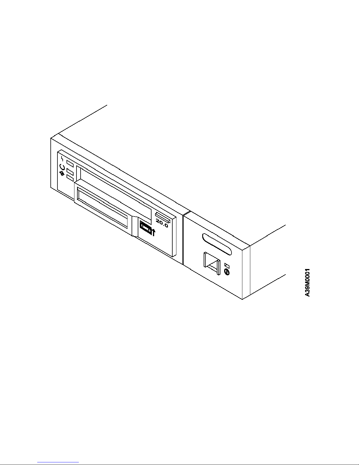
The 7208 20GB External 8mm Tape Drive Model 341 is an external storage device that connects to the IBM RS/6000 and stores
additional data.
The 7208 Tape Drive can:
Save and restore system data files
Archive important records
Distribute upgrades to operating system software
The 7208 Tape Drive Model 341 uses a fast/wide differential interface and
meets the Small Computer Systems Interface-2 (SCSI-2) standard X3.131-1994
of the American National Standards Institute (ANSI).
Figure 1 shows the front view of the 7208 Tape Drive.
Figure 1. Front View of the 7208 Tape Drive Model 341
The 7208 Tape Drive Model 341 features the following:
Tape cartridge capacity of up to 20GB per cartridge (where GB equals 1 000 000 000 bytes).
Data transfer rate of 3MB per second (where MB equals 1 000 000 bytes).
Data compression hardware that increases tape cartridge capacity up to 40GB and transfer rate up to 6MB per second. (This feature
is controlled by the system software and does not require special handling by the 7208 Tape Drive operator.)
Note: The actual capacity per cartridge varies, depending on the application and the type of data cartridge being used.
A liquid crystal display (LCD) that provides operating and error messages.
Subtopics
1.1 System Requirement
1.2 Enabling the 7208 Tape Drive as an IPL Device
1.3 Specifications
7208 Model 341 Setup and Operator Guide
Chapter 1. General Information
¦ Copyright IBM Corp. 1997
1.0 - 1
Page 17

1.1 System Requirement
The system requirement for the 7208 Tape Drive is any RS/6000 platform with an AIX operating system at level 4.1.5, 4.2, or higher.
7208 Model 341 Setup and Operator Guide
System Requirement
¦ Copyright IBM Corp. 1997
1.1 - 1
Page 18

1.2 Enabling the 7208 Tape Drive as an IPL Device
The 7208 Tape Drive has been enabled as an initial program load (IPL) device for certain models of the RS/6000. The applicable
RS/6000 models and their required firmware are:
RS/6000 Machine Type Required Level and Model Number of System Firmware
7043 Model 140 TIG97038 or later
7043 Model 240 DOR97038 or later
7025 Model F40 TR97038 or later
7026 Model H10 TR97038 or later
Note: To determine your current level of firmware and to obtain a firmware upgrade, refer to instructions that may be included with your
7208 Tape Drive or check your RS/6000 service documentation.
7208 Model 341 Setup and Operator Guide
Enabling the 7208 Tape Drive as an IPL Device
¦ Copyright IBM Corp. 1997
1.2 - 1
Page 19

1.3 Specifications
+------------------------------------------------------------------------+
¦ Figure 2. Specifications for the 7208 Tape Drive Model 341 ¦
+------------------------------------------------------------------------¦
¦ Physical Specifications ¦
+------------------------------------------------------------------------¦
¦ Width ¦ 250 mm (9.8 in.) ¦
+-----------------------+------------------------------------------------¦
¦ Depth ¦ 275 mm (10.8 in.) ¦
+-----------------------+------------------------------------------------¦
¦ Height ¦ 55 mm (2.2 in.) ¦
+-----------------------+------------------------------------------------¦
¦ Weight ¦ 5 kg (11 lb) ¦
+------------------------------------------------------------------------¦
¦ Power Specifications ¦
+------------------------------------------------------------------------¦
¦ kVA ¦ 0.041 ¦
+-----------------------+------------------------------------------------¦
¦ V ac ¦ 100 to 125, or 200 to 240 ¦
+-----------------------+------------------------------------------------¦
¦ Hertz ¦ 50 to 60 ¦
+-----------------------+------------------------------------------------¦
¦ Btu Average (watts) ¦ 67 Btu/hr (20 watts) ¦
+-----------------------+------------------------------------------------¦
¦ Power Factor ¦ 0.58 ¦
+------------------------------------------------------------------------¦
¦ Other Specifications ¦
+------------------------------------------------------------------------¦
¦ Maximum Altitude ¦ 3048 m (10,000 ft) ¦
+------------------------------------------------------------------------¦
¦ Recommended Environment ¦
+------------------------------------------------------------------------¦
¦ Environmental ¦ Operating ¦ Storage ¦ Shipping ¦
¦ Factor ¦ ¦ ¦ ¦
+-----------------+------------------+-----------------+-----------------¦
¦ Temperature ¦ 16 to 32°C ¦ 1 to 60°C ¦ -40 to 60°C ¦
¦ ¦ (60 to 90°F) ¦ (34 to 140°F) ¦ (-40 to 140°F) ¦
+-----------------+------------------+-----------------+-----------------¦
¦ Relative ¦ ¦ ¦ ¦
¦ Humidity ¦ 20 to 80% ¦ 10 to 80% ¦ 10 to 90% ¦
¦ (noncondensing) ¦ ¦ ¦ ¦
+-----------------+------------------+-----------------+-----------------¦
¦ Maximum Wet ¦ 23°C ¦ 29°C ¦ 29°C ¦
¦ Bulb ¦ (73°F) ¦ (84°F) ¦ (84°F) ¦
+------------------------------------------------------------------------¦
¦ Note: The operating limits include media. The storage and shipping ¦
¦ limits do not include media. For media storage and shipping limits, ¦
¦ see "Storage and Shipping Environments" in topic 5.2. ¦
+------------------------------------------------------------------------+
7208 Model 341 Setup and Operator Guide
Specifications
¦ Copyright IBM Corp. 1997
1.3 - 1
Page 20

2.0 Chapter 2. Setting Up the 7208 Tape Drive
This topic provides step-by-step instructions on how to properly install the 7208 Tape Drive Model 341.
DANGER
+--------------------------------------------------------+
PICTURE 4 ¦ To prevent a possible electrical shock when adding or ¦
¦ removing any devices to or from the system, ensure ¦
¦ that the power cords for those devices are unplugged ¦
¦ before the signal cables are connected or ¦
¦ disconnected. If possible, disconnect all power cords ¦
¦ from the existing system before you add or remove a ¦
¦ device. (72XXD203) ¦
+--------------------------------------------------------+
Before installing the 7208 Tape Drive, let it acclimate to the operating
environment for as long as it has been away from the environment or for 24
hours, whichever is less.
Attention: The 7208 Tape Drive is a precision device that requires reasonable care in handling to prevent data loss or permanent
damage. Avoid bumping or dropping the 7208 Tape Drive.
To unpack the 7208 Tape Drive, simply remove the packing material from the box it was shipped in.
Subtopics
2.1 Performing the Installation
7208 Model 341 Setup and Operator Guide
Chapter 2. Setting Up the 7208 Tape Drive
¦ Copyright IBM Corp. 1997
2.0 - 1
Page 21

2.1 Performing the Installation
To install the 7208 Tape Drive, complete the following steps.
Subtopics
2.1.1 Step 1. Using the Inventory Checklist
2.1.2 Step 2. Checking the Electrical Outlets
2.1.3 Step 3. Assembling the Materials
2.1.4 Step 4. Setting the SCSI Address
2.1.5 Step 5. Placing the 7208 Tape Drive
2.1.6 Step 6. Performing a System Shutdown
2.1.7 Step 7. Connecting the SCSI Bus Cable
2.1.8 Step 8. Installing the SCSI Terminator
2.1.9 Step 9. Connecting the Power Cables
2.1.10 Step 10. Performing the 7208 Tape Drive Checkout Procedure
7208 Model 341 Setup and Operator Guide
Performing the Installation
¦ Copyright IBM Corp. 1997
2.1 - 1
Page 22

2.1.1 Step 1. Using the Inventory Checklist
Make sure that you received the following items:
Power cable (for the appropriate cable see the appendix, "Power Cables," on topic A.0)
The
External Devices Warranty Information
(U.S., Canada, and Puerto Rico only)
The
7208 20GB External 8mm Tape Drive Model 341 Setup and Operator Guide
(this guide)
The
7208 20GB External 8mm Tape Drive Model 341 Service Guide
The
External Devices Safety Information
manual
One of the following:
A system-to-device SCSI bus cable and a terminator (if the 7208 Tape Drive is the only device connected to the RS/6000)
A device-to-device SCSI bus cable (if the 7208 Tape Drive connects to another SCSI device)
Data cartridge
Test cartridge
Cleaning cartridge
7208 Model 341 Setup and Operator Guide
Step 1. Using the Inventory Checklist
¦ Copyright IBM Corp. 1997
2.1.1 - 1
Page 23

2.1.2 Step 2. Checking the Electrical Outlets
Make sure that the electrical outlets you use are properly grounded.
7208 Model 341 Setup and Operator Guide
Step 2. Checking the Electrical Outlets
¦ Copyright IBM Corp. 1997
2.1.2 - 1
Page 24

2.1.3 Step 3. Assembling the Materials
Refer to your system management or system hardware manuals to locate the information that you need to connect the 7208 Tape Drive.
__ 1. Get your system unit books now. You may find the needed information under the topics:
Installing an external SCSI tape drive
SCSI controllers
External SCSI devices
Do not continue until you have located the manual that describes how to:
__ 2. Determine where the SCSI controller is located (where you make the cable connection).
Record the controller location here PICTURE 5
__ 3. Determine an unused SCSI address for the 7208 Tape Drive.
Record the address here PICTURE 6
7208 Model 341 Setup and Operator Guide
Step 3. Assembling the Materials
¦ Copyright IBM Corp. 1997
2.1.3 - 1
Page 25

2.1.4 Step 4. Setting the SCSI Address
The SCSI address is a unique address that identifies the 7208 Tape Drive to your system unit. Use the SCSI address switch to set the
SCSI address of the 7208 Tape Drive. The switch ( 1 in Figure 3) is located on the rear of the tape drive. Figure 3 also shows the SCSI
bus cable connectors 2 , the cooling fan 3 , and the power cable connector 4 .
Note: Do not select a SCSI address that is already in use.
Figure 3. Rear View of the 7208 Tape Drive Model 341
To set the SCSI address, do the following:
Press the + or - pushbutton to set the SCSI address switch to the address that you have previously determined in "Step 3.
Assembling the Materials" in topic 2.1.3.
7208 Model 341 Setup and Operator Guide
Step 4. Setting the SCSI Address
¦ Copyright IBM Corp. 1997
2.1.4 - 1
Page 26

2.1.5 Step 5. Placing the 7208 Tape Drive
The 7208 Tape Drive can be located anywhere that is convenient to your system unit. The only restrictions are the length of the power
cord and the SCSI cable. Recommended locations are:
Away from the floor
In a horizontal position
Where the tape cartridge can be easily inserted
Where the liquid crystal display (LCD) can be easily viewed (for more information about the LCD, see "Liquid Crystal Display" in topic
3.3)
Where the airflow around the unit is not obstructed
To place the 7208 Tape Drive, do the following in sequence:
__ 1. Set the tape drive in the location that you have previously determined.
__ 2. Connect the power cable to the 7208 Tape Drive. (Do not plug it into the electrical outlet at this time.)
The external devices that attach to the system unit can be stacked. When
stacking external devices, do not place more than 30 pounds on top of the
7208 Tape Drive.
7208 Model 341 Setup and Operator Guide
Step 5. Placing the 7208 Tape Drive
¦ Copyright IBM Corp. 1997
2.1.5 - 1
Page 27

2.1.6 Step 6. Performing a System Shutdown
Attention: Do not attach the 7208 Tape Drive to a system unit that is powered on. This can damage the 7208 Tape Drive, the system
unit, or both.
To perform a system shutdown, do the following:
Note: Before doing a controlled shutdown of the system unit, notify other users who may be using the system.
__ 1. If it is on, do a controlled fast shutdown of the system unit by typing
shutdown -F from the system console. (You must have root authority to perform the shutdown; see your system administrator.)
Depending on your system configuration, the shutdown may take several minutes.
__ 2. When the message Halt Completed displays on the system console, turn off the power to the system unit.
__ 3. Turn off the power to all external devices connected to the system unit.
__ 4. Unplug the power cables to all external devices from their electrical outlets.
__ 5. Unplug the system unit power cable from the electrical outlet.
7208 Model 341 Setup and Operator Guide
Step 6. Performing a System Shutdown
¦ Copyright IBM Corp. 1997
2.1.6 - 1
Page 28

2.1.7 Step 7. Connecting the SCSI Bus Cable
To connect the SCSI bus cable, do the following:
__ 1. On the rear of the 7208 Tape Drive, insert the device connector end of the SCSI bus cable into one of the connectors. See Figure
4.
__ 2. Push in until the cable is seated.
__ 3. Tighten the two thumbscrews (finger tight).
+------------------------------------------------------------------------+
¦ ¦
¦ ¦
¦ ¦
¦ PICTURE 8 ¦
¦ ¦
¦ ¦
+------------------------------------------------------------------------+
Figure 4. Connecting the SCSI Bus Cable to the 7208 Tape Drive
__ 4. Connect the other end of the SCSI bus cable as follows:
If the 7208 Tape Drive is the only device attached to the system, connect the cable to the system unit (see Figure 5 in topic 2.1.8).
If the 7208 Tape Drive is part of a multiple-device configuration, connect the SCSI cable to the next device (see Figure 6 in topic
2.1.8).
7208 Model 341 Setup and Operator Guide
Step 7. Connecting the SCSI Bus Cable
¦ Copyright IBM Corp. 1997
2.1.7 - 1
Page 29

2.1.8 Step 8. Installing the SCSI Terminator
Make sure to install a terminator on the last device in the configuration.
To install the SCSI terminator, do the following:
Align the SCSI terminator with the appropriate connector, push in until the terminator is seated, and tighten the thumbscrews finger
tight.
If the 7208 Tape Drive is the only SCSI device attached to the system, install the terminator on one of the connectors of the 7208
Tape Drive (see Figure 5).
+------------------------------------------------------------------------+
¦ ¦
¦ ¦
¦ ¦
¦ PICTURE 9 ¦
¦ ¦
¦ ¦
+------------------------------------------------------------------------+
Figure 5. Example of Attaching One SCSI Device to the System Unit
If more than one device attaches to the system, move the terminator to the last device as shown in Figure 6.
+------------------------------------------------------------------------+
¦ ¦
¦ ¦
¦ ¦
¦ PICTURE 10 ¦
¦ ¦
¦ ¦
+------------------------------------------------------------------------+
Figure 6. Example of Attaching Multiple SCSI Devices to the System Unit
Notes:
1. The terminator and the SCSI bus cable can be connected to either the top or bottom SCSI connector on the 7208 Tape Drive.
2. Only one external terminator is required to terminate the SCSI bus. You do not need to use the terminator shipped with the 7208 Tape
Drive if a terminator has been previously installed.
7208 Model 341 Setup and Operator Guide
Step 8. Installing the SCSI Terminator
¦ Copyright IBM Corp. 1997
2.1.8 - 1
Page 30

2.1.9 Step 9. Connecting the Power Cables
To connect the power cables, do the following:
__ 1. Plug the 7208 Tape Drive power cable into an electrical outlet.
__ 2. Plug the power cables for all external devices into electrical outlets.
__ 3. Plug the system unit power cable into an electrical outlet.
__ 4. Turn on the power to all of the external devices.
__ 5. Review the information in "Indicator Lights" in topic 3.2 and "Liquid Crystal Display" in topic 3.3. Then turn on the power to the 7208
Tape Drive and watch for the following:
a. The power-on light comes on and stays on.
b. All three status lights come on, then turn off after approximately 35 seconds (indicating that the Power-On Self Test (POST) has
completed successfully).
Note: For machines with certain adapters, POST may not complete until the system is powered on.
c. A series of messages display on the LCD, ending with the message READY-NOTAPE. (If you change the display language while
powering on, the READY-NOTAPE message and all subsequent messages appear in the chosen language. For more information,
see "Changing the Display Language" in topic 3.3.1.)
__ 6. Turn on the power to the system unit.
Note: If the POST does not complete successfully, the 7208 Tape Drive has detected an internal fault and must be repaired. Contact
your service representative. Do not continue with the installation at this time.
7208 Model 341 Setup and Operator Guide
Step 9. Connecting the Power Cables
¦ Copyright IBM Corp. 1997
2.1.9 - 1
Page 31

2.1.10 Step 10. Performing the 7208 Tape Drive Checkout Procedure
To perform the checkout procedure, do the following:
__ 1. Configure the 7208 Tape Drive to the RS/6000 software by doing the following:
a. Log into the RS/6000 (AIX operating system).
Note: You must have root authority to install or remove the 7208 Tape Drive from the system. To obtain root authority, see your
system administrator.
b. At the system prompt, type lsdev -Cs scsi and press Enter. The command lists all of the SCSI devices that are connected to the
RS/6000. Figure 7 shows an example of the screen that displays. The screen lists:
1 Device name
2 Device status
3 SCSI adapter slot number
4 Description of the SCSI device
5 SCSI address (begins with 7th digit)
+------------------------------------------------------------------------+
¦ ¦
¦ ¦
¦ ¦
¦ PICTURE 11 ¦
¦ ¦
¦ ¦
+------------------------------------------------------------------------+
Figure 7. Screen Display of SCSI Devices Attached to the RS/6000
c. From the list of SCSI devices, identify the 7208 Tape Drive (listed as the Differential SCSI 8mm Tape Drive):
If the status of the 7208 Tape Drive is displayed as
Available
, the device has successfully been configured.
If the status is not displayed as
Available
, refer to Topic 2, "Maintenance Analysis Procedures," in the
7208 20GB External
8mm Tape Drive Model 341 Service Guide
. For more information about configuring the 7208 Tape Drive to the system
software, refer to your AIX or RS/6000 manuals.
d. This completes the 7208 Tape Drive installation.
Store the test cartridge and the cleaning cartridge for future use. Store all 7208 Tape Drive publications with your system manuals.
7208 Model 341 Setup and Operator Guide
Step 10. Performing the 7208 Tape Drive Checkout Procedure
¦ Copyright IBM Corp. 1997
2.1.10 - 1
Page 32

3.0 Chapter 3. Using the 7208 Tape Drive
This topic describes the operator controls and indicator lights on the 7208 Tape Drive. It also describes the liquid crystal display, gives
instructions for loading and unloading a tape cartridge, and tells how to clean the tape drive.
Figure 8 shows the front view of the 7208 Tape Drive Model 341.
Figure 8. Front View of the 7208 Tape Drive Model 341
Subtopics
3.1 Operator Controls
3.2 Indicator Lights
3.3 Liquid Crystal Display
3.4 Loading and Unloading Tape Cartridges
3.5 Cleaning the Tape Drive
7208 Model 341 Setup and Operator Guide
Chapter 3. Using the 7208 Tape Drive
¦ Copyright IBM Corp. 1997
3.0 - 1
Page 33

3.1 Operator Controls
The 7208 Tape Drive has the following operator controls.
Subtopics
3.1.1 Power Switch
3.1.2 Unload Button
7208 Model 341 Setup and Operator Guide
Operator Controls
¦ Copyright IBM Corp. 1997
3.1 - 1
Page 34

3.1.1 Power Switch
The power switch ( 4 in Figure 8 in topic 3.0) is a momentary pushbutton switch that enables the power to be turned on or off. When the
7208 Tape Drive is on, the power-on light 5 is on.
Note: The PICTURE 13 symbol located next to the power switch is an International Organization for Standardization (ISO) symbol for a
pushbutton switch.
7208 Model 341 Setup and Operator Guide
Power Switch
¦ Copyright IBM Corp. 1997
3.1.1 - 1
Page 35

3.1.2 Unload Button
The unload button 3 enables a tape cartridge to be ejected. The unload button operates only when the 7208 Tape Drive power is on. To
remove a tape cartridge, press and hold the unload button for about one second.
7208 Model 341 Setup and Operator Guide
Unload Button
¦ Copyright IBM Corp. 1997
3.1.2 - 1
Page 36

3.2 Indicator Lights
The 7208 Tape Drive has the following indicator lights.
Subtopics
3.2.1 Power-On Light
3.2.2 Status Lights
7208 Model 341 Setup and Operator Guide
Indicator Lights
¦ Copyright IBM Corp. 1997
3.2 - 1
Page 37

3.2.1 Power-On Light
When the 7208 Tape Drive is turned on, the power-on light 5 comes on and stays on.
7208 Model 341 Setup and Operator Guide
Power-On Light
¦ Copyright IBM Corp. 1997
3.2.1 - 1
Page 38

3.2.2 Status Lights
Three status lights 1 and their ISO symbols appear on the 7208 Tape Drive as follows:
PICTURE 14 Fault (amber)
PICTURE 15 Ready (green)
PICTURE 16 Activity (green)
The combinations of the lights and their definitions are shown in
Figure 9.
+------------------------------------------------------------------------+
¦ Figure 9. Definition of Status Light States ¦
+------------------------------------------------------------------------¦
¦ Status ¦ ¦ ¦
¦ Lights ¦ State ¦ Status ¦
+-------------+--------------+-------------------------------------------¦
¦ ¦ On ¦ The Power-On Self Test (POST) is running. ¦
¦ ¦ ¦ ¦
¦ PICTURE 17 ¦ On ¦ ¦
¦ ¦ ¦ ¦
¦ ¦ On ¦ ¦
+-------------+--------------+-------------------------------------------¦
¦ ¦ Off or On ¦ One of the following conditions exists: ¦
¦ ¦ ¦ ¦
¦ PICTURE 18 ¦ Off ¦ The power is off (Fault light is ¦
¦ ¦ ¦ off). ¦
¦ ¦ Off ¦ The POST has completed successfully, ¦
¦ ¦ ¦ but no tape cartridge has been ¦
¦ ¦ ¦ inserted. If the Fault light is on, ¦
¦ ¦ ¦ cleaning is required. See "Cleaning ¦
¦ ¦ ¦ the Tape Drive" in topic 3.5. ¦
+-------------+--------------+-------------------------------------------¦
¦ ¦ Off or On ¦ A tape cartridge has been inserted. ¦
¦ ¦ ¦ ¦
¦ PICTURE 19 ¦ On ¦ The 7208 Tape Drive is ready to ¦
¦ ¦ ¦ receive commands from the system ¦
¦ ¦ Flashing or ¦ (whether the Fault light is on or ¦
¦ ¦ Off ¦ off). ¦
¦ ¦ ¦ If the Fault light is on, cleaning is ¦
¦ ¦ ¦ required. See "Cleaning the Tape ¦
¦ ¦ ¦ Drive" in topic 3.5. ¦
¦ ¦ ¦ If the Activity light flashes, a tape ¦
¦ ¦ ¦ cartridge is in the drive and tape ¦
¦ ¦ ¦ movement is occurring. If the light ¦
¦ ¦ ¦ is off, no tape movement is ¦
¦ ¦ ¦ occurring. ¦
+-------------+--------------+-------------------------------------------¦
¦ ¦ Flashing ¦ The 7208 Tape Drive has detected an ¦
¦ ¦ ¦ internal fault that requires corrective ¦
¦ PICTURE 20 ¦ Off ¦ action. ¦
¦ ¦ ¦ ¦
¦ ¦ Off ¦ Reset the error by turning the power ¦
¦ ¦ ¦ off to the 7208 Tape Drive, then ¦
¦ ¦ ¦ turning it back on, or by holding ¦
¦ ¦ ¦ down the unload button for about 15 ¦
¦ ¦ ¦ seconds. ¦
¦ ¦ ¦ If the Fault light still flashes ¦
¦ ¦ ¦ after the reset, contact your service ¦
¦ ¦ ¦ representative. ¦
+-------------+--------------+-------------------------------------------¦
¦ ¦ On ¦ The tape drive requires cleaning. See ¦
¦ ¦ ¦ "Cleaning the Tape Drive" in topic 3.5. ¦
¦ PICTURE 21 ¦ Off or On ¦ ¦
¦ ¦ ¦ If the Ready light is on, a tape ¦
¦ ¦ Flashing or ¦ cartridge is in the drive. If the ¦
¦ ¦ Off ¦ light is off, a cartridge is not in ¦
¦ ¦ ¦ the drive. ¦
¦ ¦ ¦ If the Activity light flashes, a tape ¦
¦ ¦ ¦ cartridge is in the drive and tape ¦
¦ ¦ ¦ movement is occurring. If the light ¦
¦ ¦ ¦ is off, no tape movement is ¦
¦ ¦ ¦ occurring. ¦
+------------------------------------------------------------------------+
7208 Model 341 Setup and Operator Guide
Status Lights
¦ Copyright IBM Corp. 1997
3.2.2 - 1
Page 39

3.3 Liquid Crystal Display
The 7208 Tape Drive features a liquid crystal display (LCD) ( 2 in Figure 8 in topic 3.0). The LCD provides operating and error
messages.
Figure 10 shows a list of messages that display on the LCD.
+------------------------------------------------------------------------+
¦ Figure 10. LCD Messages ¦
+------------------------------------------------------------------------¦
¦ Reset Messages ¦
+------------------------------------------------------------------------¦
¦ RESET ¦ The first message to appear during the ¦
¦ ¦ power-on sequence. ¦
+-----------------------+------------------------------------------------¦
¦ MODEL: ¦ Variable information about the tape drive, in ¦
¦ ¦ this case IBM--20GB ¦
+-----------------------+------------------------------------------------¦
¦ SUBMOD: ¦ The submodel number of the tape drive. ¦
+-----------------------+------------------------------------------------¦
¦ SN: ¦ The serial number of the tape drive. ¦
+-----------------------+------------------------------------------------¦
¦ CODE: ¦ The level of the tape drive's firmware. ¦
+-----------------------+------------------------------------------------¦
¦ LAST CLN: ¦ The number of hours since the last cleaning. ¦
+-----------------------+------------------------------------------------¦
¦ COMPRESSION: ¦ Whether data compression is turned on (the ¦
¦ ¦ default) or turned off. ¦
+-----------------------+------------------------------------------------¦
¦ SINGLE ENDED or ¦ The type of SCSI input/output controller ¦
¦ DIFFERENTIAL ¦ (whether single ended or differential). ¦
+-----------------------+------------------------------------------------¦
¦ WIDE ¦ The type of SCSI configuration. ¦
+-----------------------+------------------------------------------------¦
¦ SCSI ID: ¦ The SCSI address of the tape drive (0 through ¦
¦ ¦ 15). ¦
+-----------------------+------------------------------------------------¦
¦ ¦ The current language used on the LCD. To ¦
¦ ¦ change the language, power the tape drive off. ¦
¦ LANGUAGE: ¦ Press and hold the unload button immediately ¦
¦ ¦ after turning the power back on. When the ¦
¦ ¦ desired language displays, release the unload ¦
¦ ¦ button. ¦
+------------------------------------------------------------------------¦
¦ Tape Drive Status Messages ¦
+------------------------------------------------------------------------¦
¦ READY-NOTAPE ¦ The tape drive is ready to accept a cartridge. ¦
+-----------------------+------------------------------------------------¦
¦ ¦ LOADING.... ¦ The tape drive is loading the tape. ¦
+-----------------------+------------------------------------------------¦
¦ ¦ READY-TAPE ¦ The tape drive successfully loaded the tape ¦
¦ ¦ and is ready for read or write operations. ¦
+-----------------------+------------------------------------------------¦
¦ ¦ ILLEGAL TAPE ¦ An unsuitable tape has been loaded and ¦
¦ ¦ rejected. ¦
+-----------------------+------------------------------------------------¦
¦ ¦ The unload button was pressed. The tape drive ¦
¦ << EJECT====== ¦ will eject the cartridge as soon as it ¦
¦ ¦ finishes the current operation. ¦
+-----------------------+------------------------------------------------¦
¦ ¦ EJECT PREVNT ¦ The system software has issued a command to ¦
¦ ¦ prevent the eject function. ¦
+------------------------------------------------------------------------¦
¦ Tape Motion Messages ¦
+------------------------------------------------------------------------¦
¦ ¦ The tape drive is reading data. The + sign ¦
¦ ¦ appears when the data is compressed. The ¦
¦ READ+¦¦¦¦¦= ¦ boxes (¦) represent the amount of tape ¦
¦ ¦ processed (out of a total of six boxes). The ¦
¦ ¦ = sign represents the amount of unprocessed ¦
¦ ¦ tape. ¦
+-----------------------+------------------------------------------------¦
¦ WRITE+¦¦¦¦= ¦ The tape drive is writing data. The + sign ¦
¦ ¦ appears when the data is compressed. ¦
+-----------------------+------------------------------------------------¦
¦ / PROTECTED ¦ The tape drive cannot write data because the ¦
¦ ¦ data cartridge is write-protected. ¦
+-----------------------+------------------------------------------------¦
¦ ¦ The tape drive cannot write to the type of ¦
¦ / ILLEGAL WRT ¦ data cartridge inserted. This message remains ¦
¦ ¦ until a proper tape is inserted or a tape ¦
¦ ¦ motion command is issued. ¦
+-----------------------+------------------------------------------------¦
7208 Model 341 Setup and Operator Guide
Liquid Crystal Display
¦ Copyright IBM Corp. 1997
3.3 - 1
Page 40

¦ >> SEARCH¦¦==== ¦ A high-speed search is in progress. ¦
¦ << SEARCH¦¦==== ¦ ¦
+-----------------------+------------------------------------------------¦
¦ << REWIND¦¦¦=== ¦ The rewind function is in progress. ¦
+-----------------------+------------------------------------------------¦
¦ ¦ The tape drive is erasing data on the tape. ¦
¦ ¦ ERASE¦===== ¦ As the data is erased, the equal signs (=) ¦
¦ ¦ change to boxes (¦). ¦
+------------------------------------------------------------------------¦
¦ Cleaning Messages ¦
+------------------------------------------------------------------------¦
¦ `` CLEAN SOON ¦ The tape drive needs to be cleaned. ¦
+-----------------------+------------------------------------------------¦
¦ ¦ The tape drive must be cleaned when advanced ¦
¦ `` MUST CLEAN ¦ metal-evaporated (AME) media is inserted after ¦
¦ ¦ using metal particle (MP) media. ¦
+-----------------------+------------------------------------------------¦
¦ `` CLEANING ¦ Cleaning is in progress. ¦
+-----------------------+------------------------------------------------¦
¦ ¦ The cleaning tape in the cartridge is used up ¦
¦ `` DEPLETED ¦ and the tape drive will eject it. Insert a ¦
¦ ¦ new cleaning cartridge. ¦
+------------------------------------------------------------------------¦
¦ Error Conditions ¦
+------------------------------------------------------------------------¦
¦ ¦ A hardware error has occurred. The LCD ¦
¦ ¦ displays the last three error codes, with ERR ¦
¦ LAST 3 ERRORS ¦ 1: xx yy zz as the most recent. xx = the ¦
¦ ¦ fault symptom code (FSC). yy and zz = ¦
¦ ERR 1: xx yy zz ¦ additional information for product support ¦
¦ ERR 2: xx yy zz ¦ personnel (the information may or may not be ¦
¦ ERR 3: xx yy zz ¦ present). To resolve the error, refer to ¦
¦ ¦ Appendix B, "Fault Symptom Codes and Error ¦
¦ ¦ Recovery Procedure Numbers" in topic B.0. ¦
+------------------------------------------------------------------------+
Subtopics
3.3.1 Changing the Display Language
7208 Model 341 Setup and Operator Guide
Liquid Crystal Display
¦ Copyright IBM Corp. 1997
3.3 - 2
Page 41

3.3.1 Changing the Display Language
The text on the 7208 Tape Drive LCD is available in English, French, German, Italian, Portuguese, and Spanish. To change the language:
1. Power the tape drive off.
2. Press and hold the unload button immediately after turning on the power to the 7208 Tape Drive.
3. The LCD cycles through the available languages. When the desired language displays, release the unload button.
7208 Model 341 Setup and Operator Guide
Changing the Display Language
¦ Copyright IBM Corp. 1997
3.3.1 - 1
Page 42

3.4 Loading and Unloading Tape Cartridges
To load and unload a tape cartridge, do the following. For information about the type of media to use, refer to Chapter 5, "Using the
Media" in topic 5.0.
Note: To avoid problems with loading and unloading, use only one label on a cartridge.
Subtopics
3.4.1 Loading a Tape Cartridge
3.4.2 Unloading a Tape Cartridge
7208 Model 341 Setup and Operator Guide
Loading and Unloading Tape Cartridges
¦ Copyright IBM Corp. 1997
3.4 - 1
Page 43

3.4.1 Loading a Tape Cartridge
To load a tape cartridge:
1. Make sure that the 7208 Tape Drive power is on (the power-on light should be on).
2. Grasp the cartridge 1 by the outer edges, with the window side up and the write-protect switch 2 facing you.
Note: See "Setting the Write-Protect Switch" in topic 5.4 to make sure that the write-protect switch is properly set.
Figure 11. Loading a Tape Cartridge into the 7208 Tape Drive
3. Slide the cartridge into the opening on the front of the 7208 Tape Drive until the loading mechanism pulls the cartridge into the drive and
the drive door closes (see Figure 11). The message LOADING displays.
To indicate that the load operation was successful, the message READY-TAPE displays and the Ready status light comes on.
7208 Model 341 Setup and Operator Guide
Loading a Tape Cartridge
¦ Copyright IBM Corp. 1997
3.4.1 - 1
Page 44

3.4.2 Unloading a Tape Cartridge
To unload a tape cartridge:
1. Make sure that the 7208 Tape Drive power is on (the power-on light should be on).
2. Press the unload button.
The 7208 Tape Drive rewinds, unloads, and ejects the tape. The process may take from 15 seconds to several minutes, depending on
the position of the tape and the amount of data written. On the LCD, the message EJECT displays, followed by the message
READY-NOTAPE. The status lights respond as follows:
The Ready light turns off.
The Activity light flashes during the unload operation.
The Activity light turns off when the cartridge is ejected from the tape drive.
Subtopics
3.4.2.1 Resolving Unload Error Messages
7208 Model 341 Setup and Operator Guide
Unloading a Tape Cartridge
¦ Copyright IBM Corp. 1997
3.4.2 - 1
Page 45

3.4.2.1 Resolving Unload Error Messages
If the tape cartridge fails to eject and the LCD displays the last three error messages (ERR 1 being the most recent), an error condition
has occurred. To resolve the error condition:
1. Write down the error message shown on the LCD. This may be helpful if additional analysis is needed.
2. Press the 7208 Tape Drive power switch to turn off the power.
3. Manually reset the drive by pressing the 7208 Tape Drive power switch (to turn on the power).
a. Wait approximately 35 seconds for the POST to complete.
b. Wait for the READY-TAPE message to display.
4. Press the unload button.
5. When the cartridge ejects, refer to Appendix B, "Fault Symptom Codes and Error Recovery Procedure Numbers" in topic B.0 to
resolve the error message that you wrote down in Step 1.
If the cartridge does not eject, refer to the section on manually removing
a tape cartridge in the 7208 20GB External 8mm Tape Drive Model 341
Service Guide.
7208 Model 341 Setup and Operator Guide
Resolving Unload Error Messages
¦ Copyright IBM Corp. 1997
3.4.2.1 - 1
Page 46

3.5 Cleaning the Tape Drive
Clean the 7208 Tape Drive tape drive:
After you use a metal particle (MP) tape (such as a 112-meter tape, a 160-meter tape, or all tapes that were compatible with previous
8mm drives)
After a maximum of 72 hours of tape motion
You must clean the tape drive after using MP media. If you use MP media
after using advanced metal-evaporated (AME) media, the LCD prompts you to
clean the tape drive by displaying the message MUST CLEAN.
The 7208 Tape Drive counts the number of hours of tape motion and indicates when it is time to clean the tape drive by displaying the
message CLEAN SOON and turning on the Fault status light.
To clean the tape drive, use only the IBM 8mm Cleaning Cartridge (part number 59H2898). For uninterrupted operation, have one or
more spare cleaning cartridges available.
Attention: Do not operate the 7208 Tape Drive Model 341 in a poor air-quality environment. If your environment contains an excessive
amount of particulates, they may permanently damage the media, the drive, or both. Contact your service representative for more
information.
To load the cleaning cartridge:
1. Make sure that the 7208 Tape Drive power is on and the Power-On Self Test has completed.
2. Grasp the cleaning cartridge by the outer edges, with the window side up and the write-protect switch facing you (refer to Figure 11 in
topic 3.4.1).
3. Slide the cartridge into the opening on the front of the 7208 Tape Drive until the loading mechanism pulls the cartridge into the drive and
the drive door closes.
After the cleaning cartridge has been fully inserted into the 7208 Tape Drive, the remainder of the cleaning process is automatic. The
7208 Tape Drive:
1. Loads the cleaning tape into the tape drive
2. Turns on the Fault status light (if the light is off)
3. Cleans the drive by moving the cleaning tape forward for approximately two minutes (the Fault status light comes on and the message
CLEANING displays)
4. Unloads and ejects the cleaning tape when the cleaning operation is complete
5. Indicates a successful cleaning operation by turning off the Fault status light
The cleaning cartridge can be used for a minimum of 18 cleaning operations. If you attempt to use the depleted cartridge, the 7208 Tape
Drive automatically detects the error, ejects the cartridge, and displays the message DEPLETED. The Fault status light remains on to
indicate that cleaning is still required. Replace the depleted cartridge with a new cleaning cartridge.
7208 Model 341 Setup and Operator Guide
Cleaning the Tape Drive
¦ Copyright IBM Corp. 1997
3.5 - 1
Page 47

4.0 Chapter 4. Removing the 7208 Tape Drive
DANGER
+--------------------------------------------------------+
PICTURE 23 ¦ To prevent a possible electrical shock when adding or ¦
¦ removing any devices to or from the system, ensure ¦
¦ that the power cords for those devices are unplugged ¦
¦ before the signal cables are connected or ¦
¦ disconnected. If possible, disconnect all power cords ¦
¦ from the existing system before you add or remove a ¦
¦ device. (72XXD203) ¦
+--------------------------------------------------------+
Attention: Damage as a result of improper handling may void your
equipment warranty.
Subtopics
4.1 Removal Checklist
7208 Model 341 Setup and Operator Guide
Chapter 4. Removing the 7208 Tape Drive
¦ Copyright IBM Corp. 1997
4.0 - 1
Page 48

4.1 Removal Checklist
When moving the 7208 Tape Drive, perform the following steps:
Attention: Failure to perform the following steps in sequence before you add or delete a device may result in data loss or a system fault.
__ 1. If loaded, remove the tape cartridge from the drive by pressing the unload button while the 7208 Tape Drive power is on.
__ 2. Remove the 7208 Tape Drive from the system configuration (for instructions, refer to your system manuals).
Attention: Failure to inform the operating system before you add or delete a device may result in data loss or a system fault.
__ 3. If it is on, do a controlled shutdown of the system unit. Refer to "Step 6. Performing a System Shutdown" in topic 2.1.6.
__ 4. Turn off the power to the 7208 Tape Drive.
__ 5. Turn off the power to all external devices attached to the system.
__ 6. Turn off the power to the system unit.
__ 7. Unplug the power cable for the 7208 Tape Drive from the electrical outlet.
__ 8. Unplug the system unit power cable from the electrical outlet.
Attention: When SCSI bus cables are connected to a system unit, they must also be connected to a device. Do not leave the SCSI bus
cable connected to the system if the device for that cable has been removed.
__ 9. Disconnect the SCSI bus cable from the system unit.
__ 10. Disconnect the SCSI bus cable from the 7208 Tape Drive.
__ 11. Ensure that the terminator is on the last device on the SCSI bus (see "Step 8. Installing the SCSI Terminator" in topic 2.1.8).
__ 12. Remove the 7208 Tape Drive and place it in the new location.
__ 13. Reinstall the 7208 Tape Drive (refer to Chapter 2, "Setting Up the 7208 Tape Drive" in topic 2.0).
7208 Model 341 Setup and Operator Guide
Removal Checklist
¦ Copyright IBM Corp. 1997
4.1 - 1
Page 49

5.0 Chapter 5. Using the Media
Observe the following guidelines for using media with the 7208 Tape Drive Model 341:
Attention: Do not use video-grade cartridges, as they are hazardous to the 7208 Tape Drive and will void your warranty.
Before using a cartridge, let it acclimate to the operating environment for as long as it has been away from the environment or for 24
hours, whichever is less.
Use only IBM 8mm cartridges with the 7208 Tape Drive Model 341. The 7208 Tape Drive:
- Reads from and writes to advanced metal-evaporated (AME) cartridges
- Reads from metal particle (MP) cartridges
To order tape cartridges, see "Ordering Tape Cartridges" in topic 5.5.
Attention: Clean the 7208 Tape Drive tape drive:
- After you use an MP tape cartridge prior to using an AME cartridge
- Whenever you replace a worn tape
- Whenever you replace a defective tape
- Whenever the CLEANING message displays
For more information, see "Cleaning the Tape Drive" in topic 3.5.
Do not write to previously written software distribution tapes. Often these tapes will not support being rewritten without modifications to
the cartridge. If the cartridge is modified, it is possible to cause tape jams or tape misalignment.
Back up and then discard any tape that repeatedly produces error messages. (The error information is in the System Error Log.)
Do not open the door that covers the tape in the data cartridge. This door protects the magnetic tape from dirt, dust, and damage.
Do not touch the tape material. Any substance transferred to the tape by touching could cause loss of data.
Do not operate the 7208 Tape Drive in a dusty environment.
Do not store tape cartridges or the 7208 Tape Drive in a dusty environment.
Store tape cartridges vertically.
Subtopics
5.1 Types of Tape Cartridges
5.2 Storage and Shipping Environments
5.3 Operating in Harsh Environments
5.4 Setting the Write-Protect Switch
5.5 Ordering Tape Cartridges
7208 Model 341 Setup and Operator Guide
Chapter 5. Using the Media
¦ Copyright IBM Corp. 1997
5.0 - 1
Page 50

5.1 Types of Tape Cartridges
The 7208 Tape Drive Model 341 is shipped with an AME data cartridge, an AME test cartridge, and a cleaning cartridge.
Data Cartridge
Use the AME data cartridge for saving or restoring your programs or data.
To avoid problems with loading and unloading a tape, use only one label on the tape cartridge. Place the label in location 1 or 2 as
shown in Figure 12.
Figure 12. Placement of Label on an 8mm Data Cartridge
Test Cartridge
Reserve the specially labeled test tape cartridge to perform diagnostics on the drive. Do not use it to save or restore programs or data.
Cleaning Cartridge
Use the specially labeled cleaning cartridge to clean the 7208 Tape Drive tape drive (see "Cleaning the Tape Drive" in topic 3.5).
To order additional cartridges, refer to "Ordering Tape Cartridges" in topic 5.5.
7208 Model 341 Setup and Operator Guide
Types of Tape Cartridges
¦ Copyright IBM Corp. 1997
5.1 - 1
Page 51

5.2 Storage and Shipping Environments
Before using the cartridges, let them acclimate to the operating environment by placing the cartridge in the operating environment for as
long as it has been away from the environment or for 24 hours, whichever is less.
Acclimation is necessary on any data cartridge exposed to a different humidity environment or to temperature changes of 11°C (20°F) or
more.
The 8mm data cartridge can be stored and shipped in a variety of environments. Figure 13 provides a description of these environments.
+------------------------------------------------------------------------+
¦ Figure 13. Recommended Environment for 8mm Data Cartridges ¦
+------------------------------------------------------------------------¦
¦ Environmental Factor ¦ Storage ¦ Shipping ¦
+-----------------------+------------------------+-----------------------¦
¦ Temperature ¦ 5°C to 32°C ¦ -40 to 45°C ¦
¦ ¦ (41° to 90°F) ¦ (-40 to 113°F) ¦
+-----------------------+------------------------+-----------------------¦
¦ Relative Humidity ¦ 20 to 60% ¦ 5 to 80% ¦
¦ (noncondensing) ¦ ¦ ¦
+-----------------------+------------------------+-----------------------¦
¦ Maximum Wet Bulb ¦ 26°C ¦ 26°C ¦
¦ ¦ (79°F) ¦ (79°F) ¦
+------------------------------------------------------------------------+
7208 Model 341 Setup and Operator Guide
Storage and Shipping Environments
¦ Copyright IBM Corp. 1997
5.2 - 1
Page 52

5.3 Operating in Harsh Environments
The 7208 Tape Drive is ideally suited to streaming operations, as opposed to multiple stop-and-start, random-search tape operations.
When the tape is used for frequent stop-and-start operations, it is beneficial to still have as much streaming movement as possible. This
can be accomplished by assuring that any save or restore operation is the only active operation being performed by a device connected to
the SCSI I/O controller.
Do not use as an archival tape any tape that has been used outside of the ranges specified in Figure 13 in topic 5.2 for an extended
period of time. The magnetic and physical strength of the tape will have deteriorated as a result of its exposure to the environment. Do not
store important data on such a tape; transfer the data to a newer tape for reliable archiving.
7208 Model 341 Setup and Operator Guide
Operating in Harsh Environments
¦ Copyright IBM Corp. 1997
5.3 - 1
Page 53

5.4 Setting the Write-Protect Switch
The position of the write-protect switch on the 8mm tape cartridge determines when you can write to the tape.
When the switch is set to SAVE 1 , data cannot be written to the tape.
When the switch is set to REC (Record) 2 , data can be written to and read from the tape.
Figure 14 shows the write-protect switch in the REC and SAVE positions.
An attempt to write to a data cartridge with the switch in the SAVE position will cause an error.
7208 Model 341 Setup and Operator Guide
Setting the Write-Protect Switch
¦ Copyright IBM Corp. 1997
5.4 - 1
Page 54

Figure 14. Setting the Write-Protect Switch
7208 Model 341 Setup and Operator Guide
Setting the Write-Protect Switch
¦ Copyright IBM Corp. 1997
5.4 - 2
Page 55

5.5 Ordering Tape Cartridges
Figure 15 lists the tape cartridges that you can order for the 7208 Tape Drive Model 341. To order cartridges in the United States and
Canada, call 1-888-IBM-MEDIA. To order cartridges in other locations, contact your local provider of IBM storage products.
+------------------------------------------------------------------------+
¦ Figure 15. Tape Cartridges for the 7208 Tape Drive Model 341 ¦
+------------------------------------------------------------------------¦
¦ IBM Part Number ¦ Type of Cartridge ¦ Length ¦
+-----------------+------------------------------------+-----------------¦
¦ 59H2671 ¦ 8mm 2.5GB AME Cartridge ¦ 22.5 m ¦
¦ ¦ (short length) ¦ (74 ft) ¦
+-----------------+------------------------------------+-----------------¦
¦ 59H2678 ¦ 8mm 20GB AME Data Cartridge ¦ 170 m ¦
¦ ¦ ¦ (558 ft) ¦
+-----------------+------------------------------------+-----------------¦
¦ 59H2898 ¦ 8mm Cleaning Cartridge ¦ -- ¦
¦ ¦ (To be used only with 20GB drives) ¦ ¦
+------------------------------------------------------------------------+
7208 Model 341 Setup and Operator Guide
Ordering Tape Cartridges
¦ Copyright IBM Corp. 1997
5.5 - 1
Page 56

A.0 Appendix A. Power Cables
To avoid electrical shock, a power cable with a grounded
PICTURE 26 attachment plug is provided. Use only properly grounded
outlets.
Power cables used in the United States and Canada are
listed by Underwriter's Laboratories and certified by the
Canadian Standards Association. The power cables consist
of:
Electrical cables, type SVT or SJT.
Attachment plugs complying with National Electrical
Manufacturers Association (NEMA) 5-15P, that is:
"For 115 V operation use a UL Listed Cable Set
consisting of a minimum 18 AWG, Type SVT or SJT three
conductor cable a maximum of 15 feet in length and a
parallel blade, grounding type attachment plug rated
at 15 A, 125 V."
"For 230 V operation in the United States use a UL
Listed Cable Set consisting of a minimum 18 AWG, Type
SVT or SJT three conductor cable a maximum of 15 feet
in length, and a tandem blade, grounding type
attachment plug rated at 15 A, 250 V."
Appliance couplers complying with International
Electrotechnical Commission (IEC) Standard 320, Sheet
C13.
Power cables used in other countries consist of:
Electrical cables, type HD21.
Attachment plugs approved by the appropriate testing
organization for the specific countries where they are
used.
"For units set at 230 V (outside of U. S.): Use a
Cable Set consisting of a minimum 18 AWG cable and
grounding type attachment plug rated 15 A, 250 V. The
Cable Set should have the appropriate safety approvals
for the country in which the equipment will be
installed and marked 'HAR'."
Figure 16 lists the power cable part number, the country
where the power cable can be used, and an index number to
be matched with the receptacles shown in Figure 17. If
your power cable does not match this information, contact
your local dealer.
+------------------------------------------------------------------------+
¦ Figure 16. Power Cable Information ¦
+------------------------------------------------------------------------¦
¦ Part Number ¦ Country ¦ Index ¦
+--------------------+-----------------------------------------+---------¦
¦ 1838574 ¦ Bahamas, Barbados, Bolivia, Brazil, ¦ 1 ¦
¦ Japan ¦ Canada, Costa Rica, Dominican Republic, ¦ ¦
¦ ¦ Ecuador, El Salvador, Guatemala, ¦ ¦
¦ ¦ Guyana, Haiti, Honduras, Jamaica, ¦ ¦
¦ ¦ Japan, Netherlands Antilles, Panama, ¦ ¦
¦ ¦ Peru, Philippines, Taiwan, Thailand, ¦ ¦
¦ ¦ Tobago, Trinidad, U.S.A. (except ¦ ¦
¦ ¦ Chicago), Venezuela ¦ ¦
+--------------------+-----------------------------------------+---------¦
¦ 6952300 ¦ Bahamas, Barbados, Bermuda, Bolivia, ¦ 2 ¦
¦ US/Canada ¦ Brazil, Canada, Cayman Islands, ¦ ¦
¦ ¦ Colombia, Costa Rica, Dominican ¦ ¦
¦ ¦ Republic, Ecuador, El Salvador, ¦ ¦
¦ ¦ Guatemala, Guyana, Haiti, Honduras, ¦ ¦
¦ ¦ Jamaica, Japan, Korea (South), Mexico, ¦ ¦
¦ ¦ Netherlands Antilles, Nicaragua, ¦ ¦
¦ ¦ Panama, Peru, Philippines, Puerto Rico, ¦ ¦
¦ ¦ Saudi Arabia, Suriname, Taiwan, ¦ ¦
¦ ¦ Trinidad, U.S.A. (except Chicago), ¦ ¦
¦ ¦ Venezuela ¦ ¦
+--------------------+-----------------------------------------+---------¦
¦ 6952301 ¦ Chicago, U.S.A. ¦ 2 ¦
¦ 6 ft ¦ ¦ ¦
¦ Chicago ¦ ¦ ¦
+--------------------+-----------------------------------------+---------¦
7208 Model 341 Setup and Operator Guide
Appendix A. Power Cables
¦ Copyright IBM Corp. 1997
A.0 - 1
Page 57

¦ 13F9940 ¦ Argentina, Australia, New Zealand ¦ 3 ¦
¦ Australia ¦ ¦ ¦
+--------------------+-----------------------------------------+---------¦
¦ 13F9979 ¦ Abu Dhabi, Austria, Belgium, Bosnia, ¦ 4 ¦
¦ France ¦ Botswana, Bulgaria, Croatia, Egypt, ¦ ¦
¦ ¦ Finland, France, Germany, Greece, ¦ ¦
¦ ¦ Iceland, Indonesia, Korea (South), ¦ ¦
¦ ¦ Lebanon, Luxembourg, Macau, Macedonia, ¦ ¦
¦ ¦ Netherlands, Norway, Portugal, Saudi ¦ ¦
¦ ¦ Arabia, Serbia, Slovenia, Spain, Sudan, ¦ ¦
¦ ¦ Sweden, Turkey ¦ ¦
+--------------------+-----------------------------------------+---------¦
¦ 13F9997 ¦ Denmark ¦ 5 ¦
¦ Denmark ¦ ¦ ¦
+--------------------+-----------------------------------------+---------¦
¦ 14F0015 ¦ Bangladesh, Burma, Pakistan, South ¦ 6 ¦
¦ South Africa ¦ Africa, Sri Lanka ¦ ¦
+--------------------+-----------------------------------------+---------¦
¦ 14F0033 ¦ Bahrain, Bermuda, Brunei, Channel ¦ 7 ¦
¦ United Kingdom ¦ Islands, Cyprus, Ghana, Hong Kong, ¦ ¦
¦ ¦ India, Iraq, Ireland, Jordan, Kenya, ¦ ¦
¦ ¦ Kuwait, Malawi, Malaysia, Nigeria, ¦ ¦
¦ ¦ Oman, People's Republic of China, ¦ ¦
¦ ¦ Qatar, Sierra Leone, Singapore, ¦ ¦
¦ ¦ Tanzania, Uganda, United Arab Emirates ¦ ¦
¦ ¦ (Dubai), United Kingdom, Zambia ¦ ¦
+--------------------+-----------------------------------------+---------¦
¦ 14F0051 ¦ Liechtenstein, Switzerland ¦ 8 ¦
¦ Switzerland ¦ ¦ ¦
+--------------------+-----------------------------------------+---------¦
¦ 14F0069 ¦ Chile, Ethiopia, Italy ¦ 9 ¦
¦ Italy ¦ ¦ ¦
+--------------------+-----------------------------------------+---------¦
¦ 14F0087 ¦ Israel ¦ 10 ¦
¦ Israel ¦ ¦ ¦
+------------------------------------------------------------------------+
7208 Model 341 Setup and Operator Guide
Appendix A. Power Cables
¦ Copyright IBM Corp. 1997
A.0 - 2
Page 58

Figure 17. Types of Receptacles
7208 Model 341 Setup and Operator Guide
Appendix A. Power Cables
¦ Copyright IBM Corp. 1997
A.0 - 3
Page 59

B.0 Appendix B. Fault Symptom Codes and Error Recovery Procedure Numbers
Use Figure 18 to resolve error messages that appear on the LCD of the 7208 Tape Drive Model 341:
1. Determine the fault symptom code (FSC) in the error message (the first two digits in the message). For example, in error message
ERR 1: AD 58 C0, the FSC is AD.
2. Locate the FSC in Figure 18 and identify the error recovery procedure (ERP) number for that FSC.
3. Locate the ERP number in Figure 19 in topic C.0, and identify the recommended error recovery procedure.
+------------------------------------------------------------------------+
¦ Figure 18. Fault Symptom Codes (FSC) and Error Recovery Procedure ¦
¦ (ERP) Numbers ¦
+------------------------------------------------------------------------¦
¦ FSC ¦ Description ¦ ERP ¦ Cause ¦
¦ ¦ ¦ Number ¦ ¦
+-----------+------------------------------------+-----------+-----------¦
¦ 02 ¦ Invalid position for WRITE ¦ 2 ¦ - ¦
+-----------+------------------------------------+-----------+-----------¦
¦ 03 ¦ Tape is write protected for WRITE ¦ 5 ¦ - ¦
+-----------+------------------------------------+-----------+-----------¦
¦ 04 ¦ LEOT encountered on current WRITE ¦ 10 ¦ - ¦
+-----------+------------------------------------+-----------+-----------¦
¦ 05 ¦ Operation has aborted (as ¦ 11 ¦ - ¦
¦ ¦ requested) ¦ ¦ ¦
+-----------+------------------------------------+-----------+-----------¦
¦ 06 ¦ LEOT encountered on the last WRITE ¦ 10 ¦ - ¦
+-----------+------------------------------------+-----------+-----------¦
¦ 08 ¦ Compression data integrity check ¦ 12 ¦ 100% ¦
¦ ¦ failed ¦ ¦ ¦
+-----------+------------------------------------+-----------+-----------¦
¦ 09 ¦ Detected LEOT during READ ¦ 10 ¦ - ¦
+-----------+------------------------------------+-----------+-----------¦
¦ 0A ¦ Length mismatch on READ ¦ 15 ¦ - ¦
+-----------+------------------------------------+-----------+-----------¦
¦ 0B ¦ Uncorrectable block on READ ¦ 8,6 ¦ T = 90% ¦
¦ ¦ ¦ ¦ D = 10% ¦
+-----------+------------------------------------+-----------+-----------¦
¦ 0C ¦ EOD encountered on READ ¦ 13 ¦ - ¦
+-----------+------------------------------------+-----------+-----------¦
¦ 0D ¦ Filemark encountered during a READ ¦ 10 ¦ - ¦
+-----------+------------------------------------+-----------+-----------¦
¦ 0E ¦ Illegal condition for READ ¦ 2 ¦ - ¦
+-----------+------------------------------------+-----------+-----------¦
¦ 0F ¦ READ issued at blank tape ¦ 4 ¦ - ¦
+-----------+------------------------------------+-----------+-----------¦
¦ 10 ¦ READ operation has aborted (as ¦ 11 ¦ - ¦
¦ ¦ requested) ¦ ¦ ¦
+-----------+------------------------------------+-----------+-----------¦
¦ 11 ¦ Too many permanent READ errors, ¦ 8,6 ¦ T = 90% ¦
¦ ¦ cannot sync ¦ ¦ D = 10% ¦
+-----------+------------------------------------+-----------+-----------¦
¦ 14 ¦ PEOT or PEOP encountered on a READ ¦ 2,8,6 ¦ - ¦
¦ ¦ or VERIFY ¦ ¦ ¦
+-----------+------------------------------------+-----------+-----------¦
¦ 15 ¦ Bad filemark encountered during a ¦ 8,6 ¦ T = 100% ¦
¦ ¦ READ ¦ ¦ ¦
+-----------+------------------------------------+-----------+-----------¦
¦ 16 ¦ Medium error detected during a ¦ 8,6 ¦ T = 90% ¦
¦ ¦ READ ¦ ¦ D = 10% ¦
+-----------+------------------------------------+-----------+-----------¦
¦ 17 ¦ Hardware error during a READ ¦ 12 ¦ D = 100% ¦
+-----------+------------------------------------+-----------+-----------¦
¦ 18 ¦ READ decompression failed - HW ¦ 12 ¦ D = 100% ¦
¦ ¦ error ¦ ¦ ¦
+-----------+------------------------------------+-----------+-----------¦
¦ 19 ¦ READ decompression CRC failed ¦ 12 ¦ D = 100% ¦
+-----------+------------------------------------+-----------+-----------¦
¦ 1C ¦ Unknown or incompatible format ¦ 14 ¦ T = 100% ¦
+-----------+------------------------------------+-----------+-----------¦
¦ 1D ¦ Hit setmark on READ ¦ 10 ¦ - ¦
+-----------+------------------------------------+-----------+-----------¦
¦ 26 ¦ Not at legal place to WFM ¦ 2 ¦ - ¦
+-----------+------------------------------------+-----------+-----------¦
¦ 27 ¦ Tape is write protected for WFM ¦ 5 ¦ - ¦
+-----------+------------------------------------+-----------+-----------¦
¦ 28 ¦ LEOT encountered during WFM ¦ 10 ¦ - ¦
+-----------+------------------------------------+-----------+-----------¦
¦ 31 ¦ Setmark detected on SPACE/LOCATE ¦ 10 ¦ - ¦
+-----------+------------------------------------+-----------+-----------¦
¦ 32 ¦ Filemark detected during ¦ 10 ¦ - ¦
7208 Model 341 Setup and Operator Guide
Appendix B. Fault Symptom Codes and Error Recovery Procedure Numbers
¦ Copyright IBM Corp. 1997
B.0 - 1
Page 60

¦ ¦ SPACE/LOCATE ¦ ¦ ¦
+-----------+------------------------------------+-----------+-----------¦
¦ 33 ¦ EOD encountered on SPACE/LOCATE ¦ 10 ¦ - ¦
+-----------+------------------------------------+-----------+-----------¦
¦ 34 ¦ PEOT encountered on SPACE/LOCATE ¦ 8,6 ¦ - ¦
+-----------+------------------------------------+-----------+-----------¦
¦ 35 ¦ PBOT encountered on SPACE/LOCATE ¦ 2 ¦ - ¦
+-----------+------------------------------------+-----------+-----------¦
¦ 36 ¦ Format error during SPACE/LOCATE ¦ 8,6 ¦ T = 80% ¦
¦ ¦ ¦ ¦ D = 20% ¦
+-----------+------------------------------------+-----------+-----------¦
¦ 37 ¦ Uncorrectable block during a ¦ 8,6 ¦ T = 90% ¦
¦ ¦ SPACE/LOCATE ¦ ¦ D = 10% ¦
+-----------+------------------------------------+-----------+-----------¦
¦ 38 ¦ Medium error during SPACE/LOCATE ¦ 8,6 ¦ T = 80% ¦
¦ ¦ ¦ ¦ D = 20% ¦
+-----------+------------------------------------+-----------+-----------¦
¦ 3A ¦ Bad filemark during SPACE (2.3GB ¦ 3 ¦ T = 100% ¦
¦ ¦ mode only) ¦ ¦ ¦
+-----------+------------------------------------+-----------+-----------¦
¦ 3B ¦ SPACE/LOCATE has aborted (as ¦ 11 ¦ - ¦
¦ ¦ requested) ¦ ¦ ¦
+-----------+------------------------------------+-----------+-----------¦
¦ 3D ¦ Lost in space ¦ 8,6 ¦ T = 80% ¦
¦ ¦ ¦ ¦ D = 20% ¦
+-----------+------------------------------------+-----------+-----------¦
¦ 47 ¦ Incompatible medium rejected after ¦ 14 ¦ - ¦
¦ ¦ loading ¦ ¦ ¦
+-----------+------------------------------------+-----------+-----------¦
¦ 4B ¦ Illegal position for ERASE ¦ 2 ¦ - ¦
+-----------+------------------------------------+-----------+-----------¦
¦ 4C ¦ Tape is write protected for ERASE ¦ 5 ¦ - ¦
+-----------+------------------------------------+-----------+-----------¦
¦ 4E ¦ ERASE has aborted (as requested) ¦ 11 ¦ - ¦
+-----------+------------------------------------+-----------+-----------¦
¦ 58 ¦ Hardware error during SEND ¦ 12 ¦ D = 100% ¦
¦ ¦ DIAGNOSTIC ¦ ¦ ¦
+-----------+------------------------------------+-----------+-----------¦
¦ 61 ¦ Header in wrong format when ¦ 8,6 ¦ T = 100% ¦
¦ ¦ loading ucode ¦ ¦ ¦
+-----------+------------------------------------+-----------+-----------¦
¦ 63 ¦ Control load image not valid ¦ 8,6 ¦ T = 100% ¦
+-----------+------------------------------------+-----------+-----------¦
¦ 65 ¦ EEPROM load image not valid ¦ 8,6 ¦ T = 100% ¦
+-----------+------------------------------------+-----------+-----------¦
¦ 66 ¦ Boot code old ¦ 8,6 ¦ T = 100% ¦
+-----------+------------------------------------+-----------+-----------¦
¦ 67 ¦ Cannot program one of the memories ¦ 12 ¦ D = 100% ¦
+-----------+------------------------------------+-----------+-----------¦
¦ 69 ¦ CRC in load image was not correct ¦ 8,6 ¦ T = 100% ¦
+-----------+------------------------------------+-----------+-----------¦
¦ 6D ¦ Read buffer command failed ¦ 12 ¦ D = 100% ¦
+-----------+------------------------------------+-----------+-----------¦
¦ 71 ¦ Illegal position to format ¦ 2 ¦ - ¦
¦ ¦ partition ¦ ¦ ¦
+-----------+------------------------------------+-----------+-----------¦
¦ 72 ¦ Partitions are too big for tape ¦ 2 ¦ - ¦
+-----------+------------------------------------+-----------+-----------¦
¦ 74 ¦ Partition format of tape failed ¦ 8,6 ¦ - ¦
+-----------+------------------------------------+-----------+-----------¦
¦ 75 ¦ Partition format aborted ¦ 8,6 ¦ - ¦
+-----------+------------------------------------+-----------+-----------¦
¦ 79 ¦ Failed position to a new partition ¦ 8,6 ¦ - ¦
+-----------+------------------------------------+-----------+-----------¦
¦ 7A ¦ Partition switch aborted ¦ 11 ¦ - ¦
+-----------+------------------------------------+-----------+-----------¦
¦ 8C ¦ Software hang, we are very ¦ 12 ¦ D = 100% ¦
¦ ¦ confused ¦ ¦ ¦
+-----------+------------------------------------+-----------+-----------¦
¦ 8D ¦ Software detects a hardware ¦ 12 ¦ D = 100% ¦
¦ ¦ problem ¦ ¦ ¦
+-----------+------------------------------------+-----------+-----------¦
¦ 93 ¦ Detect PEOP ¦ 10 ¦ - ¦
+-----------+------------------------------------+-----------+-----------¦
¦ 94 ¦ Write Setmark failure ¦ 6 ¦ - ¦
+-----------+------------------------------------+-----------+-----------¦
¦ 95 ¦ WRITE failure after retry limit ¦ 8,6 ¦ T = 70% ¦
¦ ¦ exceeded ¦ ¦ D = 30% ¦
+-----------+------------------------------------+-----------+-----------¦
¦ 96 ¦ WFM failure after retry limit ¦ 8,6 ¦ T = 70% ¦
¦ ¦ exceeded ¦ ¦ D = 30% ¦
+-----------+------------------------------------+-----------+-----------¦
¦ 97 ¦ Write EOD failure after retry ¦ 8,6 ¦ T = 70% ¦
¦ ¦ limit exceeded ¦ ¦ D = 30% ¦
7208 Model 341 Setup and Operator Guide
Appendix B. Fault Symptom Codes and Error Recovery Procedure Numbers
¦ Copyright IBM Corp. 1997
B.0 - 2
Page 61

+-----------+------------------------------------+-----------+-----------¦
¦ 98 ¦ Fill error, invalid BRT ¦ 12 ¦ D = 100% ¦
+-----------+------------------------------------+-----------+-----------¦
¦ 99 ¦ Fill error, buffer empty ¦ 12 ¦ D = 100% ¦
+-----------+------------------------------------+-----------+-----------¦
¦ 9A ¦ Deformatter interrupt timeout on ¦ 12 ¦ D = 100% ¦
¦ ¦ search ¦ ¦ ¦
+-----------+------------------------------------+-----------+-----------¦
¦ 9B ¦ Overwrite (bad readback check ¦ 8,6 ¦ D = 50% ¦
¦ ¦ block type) ¦ ¦ T = 50% ¦
+-----------+------------------------------------+-----------+-----------¦
¦ 9C ¦ Formatter interrupt timeout on ¦ 12 ¦ D = 100% ¦
¦ ¦ WRITE ¦ ¦ ¦
+-----------+------------------------------------+-----------+-----------¦
¦ 9D ¦ Permanent write error, write ¦ 8,6 ¦ T = 70% ¦
¦ ¦ recovery fail ¦ ¦ D = 30% ¦
+-----------+------------------------------------+-----------+-----------¦
¦ 9E ¦ Permanent write error rewrite ¦ 8,6 ¦ T = 70% ¦
¦ ¦ threshold ¦ ¦ D = 30% ¦
+-----------+------------------------------------+-----------+-----------¦
¦ 9F ¦ Servo zone readback check failure ¦ 8,6 ¦ T = 70% ¦
¦ ¦ ¦ ¦ D = 30% ¦
+-----------+------------------------------------+-----------+-----------¦
¦ A1 ¦ Head sync error during WRITE ¦ 8,6 ¦ D = 90% ¦
¦ ¦ ¦ ¦ T = 10% ¦
+-----------+------------------------------------+-----------+-----------¦
¦ A2 ¦ Underrun error during WRITE ¦ 12 ¦ D = 100% ¦
+-----------+------------------------------------+-----------+-----------¦
¦ A3 ¦ IPORT write buffer parity error ¦ 12 ¦ D = 100% ¦
+-----------+------------------------------------+-----------+-----------¦
¦ A4 ¦ DPORT WRITE parity error ¦ 12 ¦ D = 100% ¦
+-----------+------------------------------------+-----------+-----------¦
¦ A5 ¦ PPORT WRITE parity error ¦ 12 ¦ D = 100% ¦
+-----------+------------------------------------+-----------+-----------¦
¦ A6 ¦ IPORT READ parity error ¦ 12 ¦ D = 100% ¦
+-----------+------------------------------------+-----------+-----------¦
¦ A7 ¦ DPORT READ parity error ¦ 12 ¦ D = 100% ¦
+-----------+------------------------------------+-----------+-----------¦
¦ A8 ¦ PPORT READ parity error ¦ 12 ¦ D = 100% ¦
+-----------+------------------------------------+-----------+-----------¦
¦ AC ¦ Servo software error ¦ 12 ¦ D = 100% ¦
+-----------+------------------------------------+-----------+-----------¦
¦ AD ¦ Servo hardware error ¦ 8,6 ¦ T = 90% ¦
¦ ¦ ¦ ¦ D = 10% ¦
+-----------+------------------------------------+-----------+-----------¦
¦ AE ¦ Not tracking ¦ 8,6 ¦ T = 60% ¦
¦ ¦ ¦ ¦ D = 40% ¦
+-----------+------------------------------------+-----------+-----------¦
¦ AF ¦ EOT encountered during a motion ¦ 2 ¦ D = 100% ¦
¦ ¦ command ¦ ¦ ¦
+-----------+------------------------------------+-----------+-----------¦
¦ B0 ¦ Not tracking - loss of PLL ¦ 8,6 ¦ T = 60% ¦
¦ ¦ ¦ ¦ D = 40% ¦
+-----------+------------------------------------+-----------+-----------¦
¦ B3 ¦ LBOT WRITE failure ¦ 8,6 ¦ T = 70% ¦
¦ ¦ ¦ ¦ D = 30% ¦
+-----------+------------------------------------+-----------+-----------¦
¦ B4 ¦ LBOT ATM write failure ¦ 8,6 ¦ T = 70% ¦
¦ ¦ ¦ ¦ D = 30% ¦
+-----------+------------------------------------+-----------+-----------¦
¦ B5 ¦ Read manager could not read LBOT ¦ 8,6 ¦ T = 70% ¦
¦ ¦ ¦ ¦ D = 30% ¦
+-----------+------------------------------------+-----------+-----------¦
¦ B6 ¦ EOT encountered during buffer ¦ 2 ¦ - ¦
¦ ¦ flush ¦ ¦ ¦
+-----------+------------------------------------+-----------+-----------¦
¦ C0 ¦ Power-on reset occurred ¦ 3 ¦ - ¦
+-----------+------------------------------------+-----------+-----------¦
¦ C1 ¦ Tape may have been changed ¦ 3 ¦ - ¦
+-----------+------------------------------------+-----------+-----------¦
¦ C2 ¦ Mode Select parameters have ¦ 3 ¦ - ¦
¦ ¦ changed ¦ ¦ ¦
+-----------+------------------------------------+-----------+-----------¦
¦ C3 ¦ New ucode was loaded ¦ 3 ¦ - ¦
+-----------+------------------------------------+-----------+-----------¦
¦ C4 ¦ Operator requested media removal ¦ 11 ¦ - ¦
+-----------+------------------------------------+-----------+-----------¦
¦ C5 ¦ Incompatible media was rejected ¦ 14 ¦ - ¦
+-----------+------------------------------------+-----------+-----------¦
¦ C6 ¦ Not ready, cause not known ¦ 7.3 ¦ - ¦
+-----------+------------------------------------+-----------+-----------¦
¦ C7 ¦ Not ready, in process of becoming ¦ 3 ¦ - ¦
¦ ¦ ready ¦ ¦ ¦
+-----------+------------------------------------+-----------+-----------¦
7208 Model 341 Setup and Operator Guide
Appendix B. Fault Symptom Codes and Error Recovery Procedure Numbers
¦ Copyright IBM Corp. 1997
B.0 - 3
Page 62

¦ C8 ¦ A backup positioning command is ¦ 2 ¦ - ¦
¦ ¦ required ¦ ¦ ¦
+-----------+------------------------------------+-----------+-----------¦
¦ C9 ¦ Command requires a tape and none ¦ 7.3 ¦ - ¦
¦ ¦ is loaded ¦ ¦ ¦
+-----------+------------------------------------+-----------+-----------¦
¦ CA ¦ Log Threshold met ¦ 3 ¦ - ¦
+-----------+------------------------------------+-----------+-----------¦
¦ CB ¦ Log Parameter changed ¦ 3 ¦ - ¦
+-----------+------------------------------------+-----------+-----------¦
¦ CC ¦ Parameter List Length error in CDB ¦ 2 ¦ - ¦
+-----------+------------------------------------+-----------+-----------¦
¦ CD ¦ Illegal Operation Code ¦ 2 ¦ - ¦
+-----------+------------------------------------+-----------+-----------¦
¦ CE ¦ Invalid field or reserved bits set ¦ 2 ¦ - ¦
¦ ¦ in CDB ¦ ¦ ¦
+-----------+------------------------------------+-----------+-----------¦
¦ CF ¦ This LUN is not supported ¦ 2 ¦ - ¦
+-----------+------------------------------------+-----------+-----------¦
¦ D0 ¦ Invalid field in Parameter List ¦ 2 ¦ - ¦
¦ ¦ (Mode Data) ¦ ¦ ¦
+-----------+------------------------------------+-----------+-----------¦
¦ D1 ¦ Illegal bit set in identify ¦ 2 ¦ - ¦
¦ ¦ message ¦ ¦ ¦
+-----------+------------------------------------+-----------+-----------¦
¦ D2 ¦ Media removal is prevented ¦ 2 ¦ - ¦
+-----------+------------------------------------+-----------+-----------¦
¦ D3 ¦ Command has mode mismatch ¦ 2 ¦ - ¦
¦ ¦ (variable/fixed) ¦ ¦ ¦
+-----------+------------------------------------+-----------+-----------¦
¦ D4 ¦ Illegal Transfer Length in CDB ¦ 2 ¦ - ¦
+-----------+------------------------------------+-----------+-----------¦
¦ D6 ¦ Tried to change Mode Parms and not ¦ 2 ¦ - ¦
¦ ¦ at LBOT ¦ ¦ ¦
+-----------+------------------------------------+-----------+-----------¦
¦ D7 ¦ Can't read medium incompatible ¦ 14 ¦ - ¦
¦ ¦ format ¦ ¦ ¦
+-----------+------------------------------------+-----------+-----------¦
¦ D8 ¦ Overlapped commands attempted bad ¦ 2 ¦ - ¦
¦ ¦ ITL nexus ¦ ¦ ¦
+-----------+------------------------------------+-----------+-----------¦
¦ DA ¦ Illegal bits set in ID message ¦ 2 ¦ - ¦
+-----------+------------------------------------+-----------+-----------¦
¦ DB ¦ Cannot write to tape not AME ¦ 14 ¦ T = 100% ¦
+-----------+------------------------------------+-----------+-----------¦
¦ DC ¦ Rounding has occurred ¦ 10 ¦ - ¦
+-----------+------------------------------------+-----------+-----------¦
¦ DD ¦ Not ready - head synch tape ¦ 7 ¦ - ¦
+-----------+------------------------------------+-----------+-----------¦
¦ DE ¦ Density not supported ¦ 2 ¦ - ¦
+-----------+------------------------------------+-----------+-----------¦
¦ E0 ¦ Aborted in CDB phase, parity or ¦ 12 ¦ - ¦
¦ ¦ other error ¦ ¦ ¦
+-----------+------------------------------------+-----------+-----------¦
¦ E1 ¦ Aborted prior to Data phase, bad ¦ 12 ¦ - ¦
¦ ¦ message ¦ ¦ ¦
+-----------+------------------------------------+-----------+-----------¦
¦ E2 ¦ Aborted in Data phase, init ¦ 12 ¦ - ¦
¦ ¦ detected error ¦ ¦ ¦
+-----------+------------------------------------+-----------+-----------¦
¦ E3 ¦ Aborted in Data phase, bad message ¦ 12 ¦ - ¦
+-----------+------------------------------------+-----------+-----------¦
¦ E4 ¦ Aborted after Data phase, bad ¦ 12 ¦ - ¦
¦ ¦ message ¦ ¦ ¦
+-----------+------------------------------------+-----------+-----------¦
¦ E5 ¦ Aborted after Data phase, other ¦ 12 ¦ - ¦
¦ ¦ error ¦ ¦ ¦
+-----------+------------------------------------+-----------+-----------¦
¦ E6 ¦ ABORT caused by SCSI Bus Parity ¦ 12 ¦ - ¦
¦ ¦ Error ¦ ¦ ¦
+-----------+------------------------------------+-----------+-----------¦
¦ E7 ¦ ABORT sent by initiator has been ¦ 12 ¦ - ¦
¦ ¦ completed ¦ ¦ ¦
+-----------+------------------------------------+-----------+-----------¦
¦ E8 ¦ Drive needs cleaning ¦ 1 ¦ - ¦
+-----------+------------------------------------+-----------+-----------¦
¦ EA ¦ Invalid mode (2.3GB) for data ¦ 2 ¦ - ¦
¦ ¦ compression ¦ ¦ ¦
+-----------+------------------------------------+-----------+-----------¦
¦ EB ¦ Download in progress ¦ 3 ¦ - ¦
+-----------+------------------------------------+-----------+-----------¦
¦ EC ¦ Log parameter overflow (recovered ¦ 10 ¦ - ¦
¦ ¦ error) ¦ ¦ ¦
+-----------+------------------------------------+-----------+-----------¦
7208 Model 341 Setup and Operator Guide
Appendix B. Fault Symptom Codes and Error Recovery Procedure Numbers
¦ Copyright IBM Corp. 1997
B.0 - 4
Page 63

¦ EE ¦ Service required ¦ 12 ¦ D = 100% ¦
+-----------+------------------------------------+-----------+-----------¦
¦ FA ¦ Serial number invalid or blank ¦ 12 ¦ D = 100% ¦
+-----------+------------------------------------+-----------+-----------¦
¦ FC ¦ Head sync value in EEPROM out of ¦ 12 ¦ D = 100% ¦
¦ ¦ range ¦ ¦ ¦
+-----------+------------------------------------+-----------+-----------¦
¦ FD ¦ EEPROM contains meaningless ¦ 12 ¦ D = 100% ¦
¦ ¦ information ¦ ¦ ¦
+------------------------------------------------------------------------¦
¦ Note: In the Cause column, T = Tape and D = Drive ¦
+------------------------------------------------------------------------+
7208 Model 341 Setup and Operator Guide
Appendix B. Fault Symptom Codes and Error Recovery Procedure Numbers
¦ Copyright IBM Corp. 1997
B.0 - 5
Page 64

C.0 Appendix C. Error Recovery Procedures
Use Figure 19 to resolve the error messages that appear on the LCD of the 7208 Tape Drive Model 341:
1. Determine the fault symptom code (FSC) in the error message. For example, in error message ERR 1: AD 58 C0, the FSC is AD.
2. Locate the FSC in Figure 18 in topic B.0 and identify the error recovery procedure (ERP) number for that FSC.
3. Locate the ERP number in Figure 19, and identify the recommended error recovery procedure. If two or more ERP codes are listed
for the fault symptom code in Figure 18 in topic B.0, perform the action for the first code, then perform the action for the second code,
and so on.
+------------------------------------------------------------------------+
¦ Figure 19. Error Recovery Procedures ¦
+------------------------------------------------------------------------¦
¦ ERP ¦ Recommended Error Recovery Procedure ¦
¦ Numbe¦ ¦
+------+-----------------------------------------------------------------¦
¦ 1 ¦ Warning Message, clean drive. ¦
+------+-----------------------------------------------------------------¦
¦ ¦ Application program error or user error using application. ¦
¦ 2 ¦ Retry operation. If this problem continues, notify application ¦
¦ ¦ provider. ¦
+------+-----------------------------------------------------------------¦
¦ 3 ¦ Reissue the failed command or command sequence. ¦
+------+-----------------------------------------------------------------¦
¦ 4 ¦ Application attempted to read a blank tape. Either write to ¦
¦ ¦ the tape or replace the tape with a tape containing data. ¦
+------+-----------------------------------------------------------------¦
¦ 5 ¦ Tape is write protected and a write or erase was attempted. ¦
¦ ¦ Either write-enable the tape or insert a write-enabled tape. ¦
+------+-----------------------------------------------------------------¦
¦ ¦ Perform the following until the operation can be completed: ¦
¦ ¦ ¦
¦ ¦ 1. Clean the drive ¦
¦ 6 ¦ 2. Retry the operation ¦
¦ ¦ 3. Clean the drive ¦
¦ ¦ 4. Replace the tape cartridge ¦
¦ ¦ 5. If the error persists and there is an error in the system ¦
¦ ¦ error log, call your service representative. ¦
+------+-----------------------------------------------------------------¦
¦ 7 ¦ Insert a data cartridge into the tape drive. ¦
+------+-----------------------------------------------------------------¦
¦ ¦ Perform one of the following actions: ¦
¦ ¦ ¦
¦ 8 ¦ Reset the tape drive by holding down the unload button ¦
¦ ¦ until the RESET message appears; then release the button. ¦
¦ ¦ Send a SCSI bus reset (a hard reset). ¦
+------+-----------------------------------------------------------------¦
¦ 9 ¦ Clean the tape drive and repeat the operation. ¦
+------+-----------------------------------------------------------------¦
¦ 10 ¦ No action is necessary. ¦
+------+-----------------------------------------------------------------¦
¦ 11 ¦ User has pushed the unload button. No action is required; the ¦
¦ ¦ tape drive performed the requested operation. ¦
+------+-----------------------------------------------------------------¦
¦ 12 ¦ The tape drive requires maintenance. ¦
+------+-----------------------------------------------------------------¦
¦ ¦ The tape drive has encountered the end of the media on a read ¦
¦ 13 ¦ or write operation. Mount the next tape and continue the tape ¦
¦ ¦ operation. ¦
+------+-----------------------------------------------------------------¦
¦ 14 ¦ The media type is not supported. Clean the drive and retry the ¦
¦ ¦ operation with supported media. ¦
+------+-----------------------------------------------------------------¦
¦ ¦ The block size requested on the read operation does not match ¦
¦ 15 ¦ the block size that the tape was written at. Change the ¦
¦ ¦ application's block size. ¦
+------------------------------------------------------------------------+
7208 Model 341 Setup and Operator Guide
Appendix C. Error Recovery Procedures
¦ Copyright IBM Corp. 1997
C.0 - 1
Page 65

BACK_1 Communicating Your Comments to IBM
7208 20GB External 8mm Tape Drive Model 341 Setup and Operator Guide
Publication No. SA37-0319-00
If you especially like or dislike anything about this book, please use one of the methods listed below to send your comments to IBM.
Whichever method you choose, make sure you send your name, address, and telephone number if you would like a reply.
Feel free to comment on specific errors or omissions, accuracy, organization, subject matter, or completeness of this book. However, the
comments you send should pertain to only the information in this manual and the way in which the information is presented. To request
additional publications, or to ask questions or make comments about the functions of IBM products or systems, you should talk to your
IBM representative or to your IBM authorized remarketer.
When you send comments to IBM, you grant IBM a nonexclusive right to use or distribute your comments in any way it believes
appropriate without incurring any obligation to you.
If you are mailing a readers' comment form (RCF) from a country other than the United States, you can give the RCF to the local IBM
branch office or IBM representative for postage-paid mailing.
If you prefer to send comments by mail, use the RCF at the back of this book.
If you prefer to send comments by FAX, use this number:
- United States and Canada: 520 799-2906
- Other countries: (1) 520 799-2906
The contact department is 61C/031.
Make sure to include the following in your note:
Title and publication number of this book
Page number or topic to which your comment applies.
7208 Model 341 Setup and Operator Guide
Communicating Your Comments to IBM
¦ Copyright IBM Corp. 1997
BACK_1 - 1
Page 66

COMMENTS Readers' Comments -- We'd Like to Hear from You
7208 20GB External 8mm Tape Drive Model 341 Setup and Operator Guide
Publication No. SA37-0319-00
Overall, how satisfied are you with the information in this book?
Legend:
1 Very satisfied
2 Satisfied
3 Neutral
4 Dissatisfied
5 Very dissatisfied
+------------------------------------------------------------------------+
¦ ¦ 1 ¦ 2 ¦ 3 ¦ 4 ¦ 5 ¦
+------------------------------------------+-----+-----+-----+-----+-----¦
¦ Overall satisfaction ¦ ¦ ¦ ¦ ¦ ¦
+------------------------------------------------------------------------+
How satisfied are you that the information in this book is:
+------------------------------------------------------------------------+
¦ ¦ 1 ¦ 2 ¦ 3 ¦ 4 ¦ 5 ¦
+------------------------------------------+-----+-----+-----+-----+-----¦
¦ Accurate ¦ ¦ ¦ ¦ ¦ ¦
+------------------------------------------+-----+-----+-----+-----+-----¦
¦ Complete ¦ ¦ ¦ ¦ ¦ ¦
+------------------------------------------+-----+-----+-----+-----+-----¦
¦ Easy to find ¦ ¦ ¦ ¦ ¦ ¦
+------------------------------------------+-----+-----+-----+-----+-----¦
¦ Easy to understand ¦ ¦ ¦ ¦ ¦ ¦
+------------------------------------------+-----+-----+-----+-----+-----¦
¦ Well organized ¦ ¦ ¦ ¦ ¦ ¦
+------------------------------------------+-----+-----+-----+-----+-----¦
¦ Applicable to your tasks ¦ ¦ ¦ ¦ ¦ ¦
+------------------------------------------------------------------------+
Please tell us how we can improve this book:
International Business Machines Corporation
Information Development
Department 61C
9000 South Rita Road
TUCSON AZ 85775-4401
Name . . . . . . . . . _______________________________________________
Company or Organization _______________________________________________
Address . . . . . . . . _______________________________________________
_______________________________________________
_______________________________________________
Phone No. . . . . . . . _______________________________________________
7208 Model 341 Setup and Operator Guide
Readers' Comments -- We'd Like to Hear from You
¦ Copyright IBM Corp. 1997
COMMENTS - 1
 Loading...