

Page 1

7207 Model 122 4GB External SLR5
Quarter-Inch Cartridge Tape Drive
IBM
Setup, Operator, and Service Guide
SA37-0400-00
Page 2

Page 3

7207 Model 122 4GB External SLR5
Quarter-Inch Cartridge Tape Drive
Setup, Operator, and Service Guide
IBM
SA37-0400-00
Page 4

Note!
Before using this information and the product it supports, be sure to read the general information under “Notices” on page v.
First Edition (October 1998)
The following paragraph does not apply to any country where such provisions are inconsistent with local law.
INTERNATIONAL BUSINESS MACHINES CORPORATION PROVIDES THIS PUBLICATION “AS IS” WITHOUT WARRANTY OF
ANY KIND, EITHER EXPRESS OR IMPLIED, INCLUDING BUT NOT LIMITED TO THE IMPLIED WARRANTIES OF
MERCHANTABILITY OR FITNESS FOR A PARTICULAR PURPOSE.
Some states do not allow disclaimer of express or implied warranties in certain transactions; therefore, this statement may not apply
to you.
Order publications through your IBM representative or the IBM branch office serving your locality. Publications are not stocked at the
address given below.
A reader’s comment form is provided at the back of this publication. If the form has been removed, address your comments about
this book to:
IBM Corporation, Department 61C, 9000 South Rita Road, Tucson, Arizona 85744-0001, U.S.A.
When you send information to IBM, you grant IBM a nonexclusive right to use or distribute the information in any way it believes
appropriate without incurring any obligation to you.
Copyright International Business Machines Corporation 1998. All rights reserved.
Note to U.S. Government Users — Documentation related to restricted rights — Use, duplication or disclosure is subject to
restrictions set forth in GSA ADP Schedule Contract with IBM Corp.
Page 5

Contents
Notices . . . . . . . . . . . . . . . . . . . . . . . . . . . . . . . . . . . . . . . . . . v
Safety Notices . . . . . . . . . . . . . . . . . . . . . . . . . . . . . . . . . . . . . . v
Danger Notices . . . . . . . . . . . . . . . . . . . . . . . . . . . . . . . . . . . . v
Caution Notices . . . . . . . . . . . . . . . . . . . . . . . . . . . . . . . . . . . . v
Attention Notices . . . . . . . . . . . . . . . . . . . . . . . . . . . . . . . . . . . vi
End of Life (EOL) Plan .................................. vi
Electronic Emission Notices ............................... vi
Trademarks . . . . . . . . . . . . . . . . . . . . . . . . . . . . . . . . . . . . . . . vii
About This Guide .................................... ix
Related Publications . . . . . . . . . . . . . . . . . . . . . . . . . . . . . . . . . . . ix
Chapter 1. General Information . . . . . . . . . . . . . . . . . . . . . . . . . . . 1
System Requirement . . . . . . . . . . . . . . . . . . . . . . . . . . . . . . . . . . . 2
Specifications . . . . . . . . . . . . . . . . . . . . . . . . . . . . . . . . . . . . . . . 2
Chapter 2. Setting Up the 7207 Tape Drive .................... 3
Performing the Installation ................................ 3
Step 1. Using the Inventory Checklist ....................... 3
Step 2. Checking the Electrical Outlets ...................... 4
Step 3. Running the Self Test ........................... 4
Step 4. Determining the SCSI Address ...................... 5
Step 5. Setting the SCSI Address ......................... 6
Step 6. Placing the 7207 Tape Drive ....................... 7
Step 7. Performing a System Shutdown ..................... 7
Step 8. Connecting the SCSI Bus Cable ..................... 8
Step 9. Installing the SCSI Bus Terminator .................... 9
Step 10. Connecting the Power Cables ..................... 10
Step 11. Performing the Checkout Procedure ................. 10
Chapter 3. Using the 7207 Tape Drive ...................... 13
Operator Controls . . . . . . . . . . . . . . . . . . . . . . . . . . . . . . . . . . . 13
Power Switch . . . . . . . . . . . . . . . . . . . . . . . . . . . . . . . . . . . . 13
Unload Button . . . . . . . . . . . . . . . . . . . . . . . . . . . . . . . . . . . . 13
Indicator Lights . . . . . . . . . . . . . . . . . . . . . . . . . . . . . . . . . . . . . 13
Power-On Light . . . . . . . . . . . . . . . . . . . . . . . . . . . . . . . . . . . 13
Status Light . . . . . . . . . . . . . . . . . . . . . . . . . . . . . . . . . . . . . 14
Loading Tape Cartridges ............................... 14
Unloading Tape Cartridges .............................. 16
Cleaning the Tape Drive ................................ 16
Chapter 4. Using the Media ............................ 19
Types of Tape Cartridges ............................... 19
Data Cartridge Usage and Erasure ......................... 19
Operating and Non-operating Environments .................... 20
Data Cartridge Compatibility ............................. 20
Technical Notes about Using SMIT ........................ 22
Tape Cartridge Efficiency ............................... 23
Setting the Write-Protect Switch ........................... 24
Ordering Tape Cartridges ............................... 24
Copyright IBM Corp. 1998 iii
Page 6

Chapter 5. Performing Service on the 7207 Tape Drive ........... 27
Safety Inspection Procedures ............................. 28
Maintenance Analysis Procedures .......................... 30
Step 1 . . . . . . . . . . . . . . . . . . . . . . . . . . . . . . . . . . . . . . . . . 32
Step 2 . . . . . . . . . . . . . . . . . . . . . . . . . . . . . . . . . . . . . . . . . 32
Step 3 . . . . . . . . . . . . . . . . . . . . . . . . . . . . . . . . . . . . . . . . . 32
Step 4 . . . . . . . . . . . . . . . . . . . . . . . . . . . . . . . . . . . . . . . . . 33
Step 5 . . . . . . . . . . . . . . . . . . . . . . . . . . . . . . . . . . . . . . . . . 33
Step 6 . . . . . . . . . . . . . . . . . . . . . . . . . . . . . . . . . . . . . . . . . 33
Step 7 . . . . . . . . . . . . . . . . . . . . . . . . . . . . . . . . . . . . . . . . . 33
Step 8 . . . . . . . . . . . . . . . . . . . . . . . . . . . . . . . . . . . . . . . . . 34
Step 9 . . . . . . . . . . . . . . . . . . . . . . . . . . . . . . . . . . . . . . . . . 34
Step 10 . . . . . . . . . . . . . . . . . . . . . . . . . . . . . . . . . . . . . . . . 34
Step 11 . . . . . . . . . . . . . . . . . . . . . . . . . . . . . . . . . . . . . . . . 34
Chapter 6. Moving the 7207 Tape Drive ..................... 37
Move Checklist . . . . . . . . . . . . . . . . . . . . . . . . . . . . . . . . . . . . . 37
Chapter 7. Parts List . . . . . . . . . . . . . . . . . . . . . . . . . . . . . . . . . 39
Appendix. Power Cables . . . . . . . . . . . . . . . . . . . . . . . . . . . . . . 41
Index . . . . . . . . . . . . . . . . . . . . . . . . . . . . . . . . . . . . . . . . . . . 45
iv 7207 Tape Drive Setup, Operator, and Service Guide
Page 7
Notices
References in this publication to IBM products, programs, or services do not imply that IBM intends to
make these available in all countries in which IBM operates.
Any reference to an IBM program or other IBM product in this publication is not intended to state or imply
that only IBM’s program or other product may be used. Any functionally equivalent program that does not
infringe any of IBM’s intellectual property rights may be used instead of the IBM product. Evaluation and
verification of operation in conjunction with other products, except those expressly designated by IBM, is
the user’s responsibility.
IBM may have patents or pending patent applications covering subject matter in this document. The
furnishing of this document does not give you any license to these patents. You can send license
inquiries, in writing, to the IBM Director of Licensing, IBM Corporation, 500 Columbus Avenue, Thornwood,
NY 10594, U.S.A.
Safety Notices
When using this product, observe the danger, caution, and attention notices contained in this guide. Each
danger and caution notice contains a reference number (72XXDxxx or 72XXCxxx). Use the reference
number to check the translation in
Examples of danger, caution, and attention notices follow.
External Devices Safety Information
, SA26-7003.
Danger Notices
A danger notice calls attention to a situation that is potentially lethal or extremely hazardous to people.
The following is a sample danger notice:
DANGER
An electrical outlet that is not correctly wired could place hazardous
voltage on metal parts of the system or the products that attach to
the system. It is the customer’s responsibility to ensure that the outlet
is correctly wired and grounded to prevent an electrical shock.
(72XXD201)
Caution Notices
A caution notice calls attention to a situation that is potentially hazardous to people because of some
existing condition. The following is a sample caution notice:
CAUTION:
Do not attempt to use the handle on the module to lift the entire device
(module and enclosure) as a unit. First remove the module; then, use two
hands to lift the enclosure.
Copyright IBM Corp. 1998 v
(72XXC356)
Page 8

Attention Notices
An attention notice indicates the possibility of damage to a program, device, or system, or to data. The
following is a sample attention notice:
Attention: Do not operate the 7207 Tape Drive in a poor air-quality environment. If your environment
contains an excessive amount of particulates, contact your service representative for more information.
End of Life (EOL) Plan
This box is a purchased unit. Therefore, it is the sole responsibility of the purchaser to dispose of it in
accordance with local laws and regulations at the time of disposal.
This unit contains recyclable materials. The materials should be recycled where facilities are available and
according to local regulations. In some areas IBM may provide a product take-back program that ensures
proper handling of the product. Contact your IBM representative for more information.
Electronic Emission Notices
The following statement applies to this IBM product. The statement for other IBM products intended for
use with this product will appear in their accompanying manuals.
7207 Model 122 4GB External SLR5 Quarter-Inch Cartridge Tape Drive
Federal Communications Commission (FCC) Statement
Note: This equipment has been tested and found to comply with the limits for a Class B digital device,
pursuant to Part 15 of the FCC Rules. These limits are designed to provide reasonable protection against
harmful interference in a residential installation. This equipment generates, uses, and can radiate radio
frequency energy and, if not installed and used in accordance with the instructions, may cause harmful
interference to radio communications. However, there is no guarantee that interference will not occur in a
particular installation. If this equipment does cause harmful interference to radio or television reception,
which can be determined by turning the equipment off and on, the user is encouraged to try to correct the
interference by one or more of the following measures:
Reorient or relocate the receiving antenna.
Increase the separation between the equipment and receiver.
Connect the equipment into an outlet on a circuit different from that to which the receiver is connected.
Consult an IBM authorized dealer or service representative for help.
Properly shielded and grounded cables and connectors must be used in order to meet FCC emission
limits. Proper cables and connectors are available from IBM authorized dealers. IBM is not responsible
for any radio or television interference caused by using other than recommended cables and connectors or
by unauthorized changes or modifications to this equipment. Unauthorized changes or modifications could
void the user's authority to operate the equipment.
This device complies with Part 15 of the FCC Rules. Operation is subject to the following two conditions:
(1) this device may not cause harmful interference, and (2) this device must accept any interference
received, including interference that may cause undesired operation.
vi 7207 Tape Drive Setup, Operator, and Service Guide
Page 9

Responsible Party:
International Business Machines Corporation
Old Orchard Road
Armonk, NY 10504
Telephone: 1-919-543-2193
Industry Canada Compliance Statement
This Class B digital apparatus meets the requirements of the Canadian Interference-Causing Equipment
Regulations.
Avis de conformité à la réglementation d'Industrie Canada
Cet appareil numérique de la classe B respecte toutes les exigences du Règlement sur le matériel
brouilleur du Canada.
European Community Compliance Statement
This product is in conformity with the protection requirements of EU Council Directive 89/336/EEC on the
approximation of the laws of the Member States relating to electromagnetic compatibility. IBM cannot
accept responsibility for any failure to satisfy the protection requirements resulting from a
non-recommended modification of the product, including the fitting of non-IBM option cards.
A declaration of Conformity with the requirements of the Directive has been signed by IBM SEMEA S.p.A.,
Via Tolmezzo, 15, Milano, Italy.
This product satisfies the Class B limits of EN55022.
Japanese Voluntary Control Council for Interference (VCCI) Statement
This product is a Class B Information Technology Equipment and conforms to the standards set by the
Voluntary Control Council for Interference by Information Technology Equipment (VCCI). This product is
aimed to be used in a domestic environment. When used near a radio or TV receiver, it may become the
cause of radio interference. Read the instructions for correct handling.
Korean Government Ministry of Communication (MOC) Statement
Please note that this device has been approved for non-business purposes and may be used in any
environment including residential areas.
Trademarks
The following terms are trademarks of the IBM Corporation in the United States or other countries or both:
AIX
IBM
RS/6000
The following terms are trademarks of other companies:
CSA Canadian Standards Association
UL Underwriter’s Laboratories
Notices vii
Page 10

viii 7207 Tape Drive Setup, Operator, and Service Guide
Page 11

About This Guide
This guide describes how to install and use the 7207 Model 122 4GB External SLR5 Quarter-Inch
Cartridge Tape Drive. It contains the following chapters:
Chapter 1, “General Information,” describes the 7207 Tape Drive, gives the system requirement, and lists
hardware specifications.
Chapter 2, “Setting Up the 7207 Tape Drive,” tells how to install the 7207 Tape Drive.
Chapter 3, “Using the 7207 Tape Drive,” describes the operator controls and indicator lights on the 7207
Tape Drive. It also tells how to load and unload a tape cartridge, how to retension the tape, and how to
clean the tape drive.
Chapter 4, “Using the Media,” describes the type of tape cartridges to use in the 7207 Tape Drive, as well
as the compatibility of various data cartridges. It also tells how to handle the cartridges, how to set the
write-protect switch, and how to order additional cartridges.
Chapter 5, “Performing Service on the 7207 Tape Drive,” gives instructions about conducting a safety
inspection and provides the maintenance analysis procedures (MAPs) required to service the 7207 Tape
Drive.
Chapter 6, “Moving the 7207 Tape Drive,” tells how to move the 7207 Tape Drive after it has been
installed.
Chapter 7, “Parts List,” provides a list of the parts that are necessary to service the 7207 Tape Drive.
The appendix, “Power Cables,” provides power cable information for different countries.
Store this guide with your system manuals.
Related Publications
External Devices Safety Information,
AIX System Management Guide: Operating System and Devices
about how to manage the AIX operating system.
SA26-7003, provides translations of danger and caution notices.
, SC23-2525, provides information
Copyright IBM Corp. 1998 ix
Page 12

x 7207 Tape Drive Setup, Operator, and Service Guide
Page 13
Chapter 1. General Information
The 7207 Model 122 4GB External SLR5 Quarter-Inch Cartridge Tape Drive
(referred to hereafter as the 7207-122 Tape Drive) is an external storage device
that connects to the IBM RS/6000 and provides additional data storage capability.
The 7207-122 Tape Drive includes hardware data compression, which enables
increased storage capacity and data rate.
The 7207-122 Tape Drive features:
Capacity of 4GB per cartridge (8GB at 2:1 data compression)
1
Sustained data rate of 380000 bits per second (760000 bits per second with
2:1 compression)
2
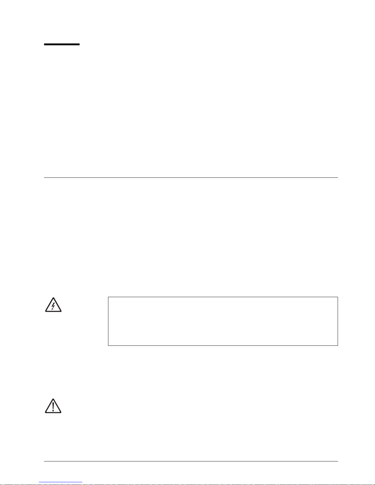
Figure 1 shows the front view of the 7207-122 Tape Drive.
Figure 1. Front View of the 7207 Model 122 4GB External SLR5 Quarter-Inch Cartridge
Tape Drive
The 7207-122 Tape Drive uses single-track linear recording (SLR5) tape drive
technology, and reads and writes to tape cartridges that are compatible with the
following recording standards defined by Quarter-Inch Cartridge Drive Standards,
Inc. (QIC):
QIC-4GB-DC (SLR5 Native Format)
QIC-2GB-DC
QIC-1000-DC
QIC-525-DC
QIC-150-DC
QIC-120-DC
A list of compatible tape cartridges and the specific recording standards to which
they are formatted is shown in “Data Cartridge Compatibility” on page 20.
The 7207-122 Tape Drive attaches to any system that uses a single-ended
interface which meets the following standards of the American National Standards
Institute (ANSI):
X3.131-1994, Small Computer System Interface-2 (SCSI-2)
X3T10/855D Revision 15A, Small Computer System Interface-3 (SCSI-3)
Parallel Interface
With the proper cables, you can attach the 7207-122 Tape Drive to a wide or
narrow SCSI bus (for a list of applicable cables, see Chapter 7, “Parts List” on
page 39). You do not need to acquire special device drivers. The 7207-122 Tape
Drive uses the native self-configuring AIX SCSI device driver.
1
1GB = one gigabyte or 1 000 000 000 bytes
2
1KB = one kilobyte or 1000 bytes
Copyright IBM Corp. 1998 1
Page 14

System Requirement
The system requirement for the 7207-122 Tape Drive is to use only a supported
RS/6000 processor or adapter, with an AIX operating system at level:
4.1.5 (with fixes as described in Authorized Program Analysis Report (APAR)
#IX69941)
4.2.0 (with fixes as described in APAR #IX69950)
4.2.1 or later
4.3.0 or later
For a list of supported processors and adapters, contact your IBM marketing
representative or business partner.
Specifications
Figure 2. Specifications for the 7207-122 Tape Drive
Physical Specifications
Width 250 mm (9.8 in.)
Depth 275 mm (10.8 in.)
Height 55 mm (2.2 in.)
Weight 3.4 kg (7 lb 8 oz)
Power Specifications
kVA 0.030 @ 120 V ac
V ac 100 to 125, or 200 to 240
Hertz 50 to 60 Hz
Btu Average (watts) 76 Btu/hr (22 watts)
Power Factor 0.3 to 0.6
Other Specifications
Maximum Altitude 2135 m (7000 ft)
Recommended Environment
Environmental Factor Operating Non-operating
Temperature
Relative Humidity
(noncondensing)
Wet Bulb Temperature
Note: The operating limits include media. The non-operating limits do not include
5 to 45°C
(41 to 113°F)
8 to 80% 10 to 90%
26°C
(79°F)
media. For media non-operating limits, see “Operating and Non-operating
Environments” on page 20.
−40 to 60°C
(−40 to 140°F)
29°C
(84°F)
2 7207 Tape Drive Setup, Operator, and Service Guide
Page 15
Chapter 2. Setting Up the 7207 Tape Drive
This chapter provides step-by-step instructions on how to properly install the
7207-122 Tape Drive.
Note: If you need assistance with the installation, contact your trained service
personnel.
DANGER
To prevent a possible electrical shock when adding or removing any
devices to or from the system, ensure that the power cords for those
devices are unplugged before the signal cables are connected or
disconnected. If possible, disconnect all power cords from the
existing system before you add or remove a device.
Before installing the 7207-122 Tape Drive, let it acclimate to the operating
environment for as long as it has been away from the environment or for 24 hours,
whichever is less.
(72XXD203)
Attention: The 7207-122 Tape Drive is a precision device that requires reasonable
care in handling to prevent data loss or permanent damage to the device. Avoid
bumping or dropping the 7207-122 Tape Drive.
To unpack the 7207-122 Tape Drive, simply remove the packing material from the
box it was shipped in.
Performing the Installation
To install the 7207-122 Tape Drive, complete the following steps.
Step 1. Using the Inventory Checklist
Make sure that you received the following items:
Power cable (for the appropriate cable see the appendix, “Power Cables,”
on page 41)
The
External Devices Warranty Information
only)
The
7207 Model 122 4GB External SLR5 Quarter-Inch Cartridge Tape Drive
Setup, Operator, and Service Guide
The
External Devices Safety Information
One of the following:
(U.S., Canada, and Puerto Rico
(this guide)
manual
Copyright IBM Corp. 1998 3
A system-to-device SCSI bus (signal) cable and a terminator (if the
7207-122 Tape Drive is the only device connected to the RS/6000)
A device-to-device SCSI bus (signal) cable (if the 7207-122 Tape Drive
connects to another SCSI device)
Page 16

Media kit that includes:
SLR5-4GB data cartridge (conforms to the QIC-4GB-DC drive standard)
SLR5-4GBSL test cartridge
Cleaning cartridge
Step 2. Checking the Electrical Outlets
Make sure that the electrical outlets that you use are properly grounded.
Step 3. Running the Self Test
Run the self test to determine whether the 7207-122 Tape Drive is functioning
properly. To run the test:
1. If the 7207-122 Tape Drive is installed, remove it by performing steps 1-12
in Chapter 6, “Moving the 7207 Tape Drive” on page 37.
Note: Make sure that the SCSI cable and terminator are not attached to
the 7207-122 Tape Drive (or the self test may not function properly).
2. Set the SCSI address switch to 9 (see “Step 5. Setting the SCSI Address”
on page 6).
3. Attach the power cable to the 7207-122 Tape Drive, then plug it into an
electrical outlet. Make sure that the power to the tape drive is off.
4. Load the SLR5-4GBSL test cartridge into the 7207-122 Tape Drive (see
“Loading Tape Cartridges” on page 14).
Note: Use only the IBM test cartridge, part number 59H3661. Use of any
other test cartridge could cause erroneous test results or lengthen
the time needed to complete the test.
5. Press the 7207-122 Tape Drive power switch to turn on the power.
After approximately 5 minutes, the status light does one of the following:
Flashes green to indicate the completion of a successful self test. Unload the
test cartridge and press the 7207-122 Tape Drive power switch to turn off the
power. Store the test cartridge in a safe location (you may need it for future
diagnostics), then go to step “Step 4. Determining the SCSI Address” on
page 5.
Flashes red to indicate an error. Replace the 7207-122 Tape Drive.
4 7207 Tape Drive Setup, Operator, and Service Guide
Page 17

Step 4. Determining the SCSI Address
The 7207-122 Tape Drive can only be set to SCSI addresses 0-7. (Addresses 8
and 9 are selectable options, but should not be used in normal operation or errors
will result; address 8 is invalid and address 9 starts the drive self test described in
the preceding step.)
Before you install the 7207-122 Tape Drive, you must find a SCSI address that is
not an address being used by another device. To find an unused SCSI address,
you must:
Identify the name and the port of the RS/6000 SCSI I/O controller that you want
to attach to
Identify the SCSI address of that SCSI I/O controller
Identify the SCSI addresses of other devices connected to that SCSI I/O
controller
Note: If you attach to a wide bus, SCSI addresses 0-15 are available but only 0-7
can be used as an address for this tape unit. Even though the 7207-122
Tape Drive uses only the range of addresses for a narrow bus, it is
designed to not impact the function of the other devices on the wide bus;
they still negotiate a wide attachment and run at appropriate data rates.
1. To identify the name and the port of an RS/6000 SCSI I/O controller that
you want to attach to, at the system prompt type lsdev -C | grep scsi and
press Enter. A list of controllers display in the following format. The names
appear in the first column (for example, scsið and scsi2). The ports appear
in the third column and in the fourth position (highlighted as follows):
Note: Column headings are for reference only; they do not appear on the
screen.
Column 1
Column 2 Column 3 Column 4
scsið Available ðð-ðð-ðS Standard SCSI I/O Controller
scsi2 Available ðð-ð2 SCSI I/O Controller
Note the name and port of the SCSI I/O controller that you want to attach to
(for example, the scsi2 controller on port 2).
2. To determine the SCSI address of the SCSI I/O controller that you noted in
the previous step, type lsattr -El scsix | grep id (where x equals the
last character in the name of the SCSI I/O controller) and press Enter. The
address of the SCSI I/O controller displays in the following format:
id 7 Adapter card SCSI I True
Note the address of the SCSI I/O controller (in this case, 7).
Chapter 2. Setting Up 5
Page 18
3. To identify the SCSI addresses used by all other devices, type
lsdev -Cs scsi and press Enter. A list of devices appears in the following
format. In the fourth position of the third column, locate all instances of the
port that you chose in step 1 on page 5. (The list may contain multiple
instances of a port. In the following example, for port 2 (identified in step 1
on page 5) there are three instances.) The addresses of the other SCSI
devices appear in the seventh position (highlighted in the example that
follows):
Column 1
hdiskð Available ðð-ðð-ðS-ð,ð 2.ðGB SCSI Disk Drive
hdisk1 Available ðð-ð2-ð1-2,ð 4.5GB 16 Bit SCSI Disk Drive
hdisk2 Available ðð-ð2-ð1-3,ð SCSI Disk Drive
rmtð Available ðð-ð2-ð1-4,ð SCSI 8mm Tape Drive
For the port chosen in step 1 on page 5, note the addresses of the other
SCSI devices attached to the RS/6000 (in this case, for port 2, the
addresses are 2, 3, and 4).
4. Determine an unused SCSI address for the 7207-122 Tape Drive (in this
case, 0 1, 5, or 6, because 7 was used by the SCSI I/O controller and 2, 3,
and 4 are used by other devices).
Column 2 Column 3 Column 4
Step 5. Setting the SCSI Address
The SCSI address is a unique address that identifies the 7207-122 Tape Drive to
your system unit. Use the SCSI address switch to set the SCSI address of the
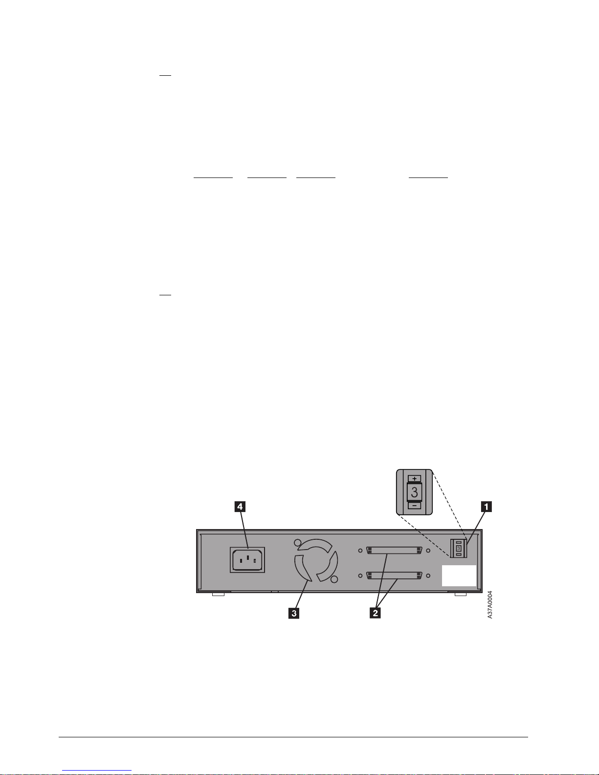
7207-122 Tape Drive. The switch (.1/ in Figure 3) is located on the rear of the
7207 Tape Drive. Figure 3 also shows the two 68-pin, wide SCSI bus cable
connectors .2/, the cooling fan .3/, and the power cable connector .4/.
Note: Set the device at the highest available address. Do not exceed address 7,
and do not select a SCSI address that is already in use (refer to “Step 4.
Determining the SCSI Address” on page 5).
Figure 3. Rear View of the 7207-122 Tape Drive
To set the SCSI address, press the + or − push button to access the address that
you have previously determined in “Step 4. Determining the SCSI Address” on
page 5.
6 7207 Tape Drive Setup, Operator, and Service Guide
Page 19

Step 6. Placing the 7207 Tape Drive
The 7207-122 Tape Drive can be located anywhere that is convenient to your
system unit. The only restrictions are the length of the power cord and the SCSI
cable. Recommended locations are:
In a clean, dirt-free environment
Away from the floor
In a horizontal position
Where the tape cartridge can be easily inserted
To place the 7207-122 Tape Drive:
1. Set the 7207-122 Tape Drive in the preferred location.
2. Connect the power cable to the 7207-122 Tape Drive. (Do not plug it into
the electrical outlet at this time.)
The external devices that attach to the system unit can be stacked. When stacking
devices, do not place more than 30 pounds on top of the 7207 Tape Drive.
Step 7. Performing a System Shutdown
Attention: Do not attach the 7207-122 Tape Drive to an RS/6000 system unit that
is powered on. This can damage the 7207 Tape Drive, the system unit, or both.
To perform a system shutdown of the RS/6000:
Note: Before doing a controlled shutdown of the system unit, notify other users
who may be using the system.
1. If it is on, do a controlled fast shutdown of the system unit by typing
shutdown -F from the system console. (You must have root authority to
perform the shutdown; see your system administrator.) Depending on your
system configuration, the shutdown may take several minutes.
2. When the message Halt Completed displays on the system console, turn
off the power to the system unit.
3. Turn off the power to all external devices connected to the system unit.
4. Unplug the power cables to all external devices from their electrical outlets.
5. Unplug the system unit power cable from the electrical outlet.
Chapter 2. Setting Up 7
Page 20

Step 8. Connecting the SCSI Bus Cable
To connect the SCSI bus cable:
1. If installed, remove the connector covers.
2. On the rear of the 7207-122 Tape Drive (.1/ in Figure 4), attach the device
connector end of the SCSI bus cable .2/ to one of the SCSI connectors
.3/.
3. Make sure that the connector is fully engaged.
4. Secure the cable to the 7207-122 Tape Drive with the thumbscrews .4/
provided on the cable.
Figure 4. Connecting the SCSI Bus Cable to the 7207-122 Tape Drive. The view is from
the side.
5. Connect the other end of the SCSI bus cable as follows:
If the 7207-122 Tape Drive is the only device attached to the system,
connect the cable to the RS/6000 (see Figure 5 on page 9).
If the 7207-122 Tape Drive is part of a multiple-device configuration,
connect the cable to the next device (see Figure 6 on page 9).
If the 7207-122 Tape Drive is installed in the middle of a narrow bus,
two 68-pin-to-50-pin device-to-device cables will be required, one for
each device on either side of the 7207-122 Tape Drive.
8 7207 Tape Drive Setup, Operator, and Service Guide
Page 21

Step 9. Installing the SCSI Bus Terminator
Make sure to install a terminator on the last device in the configuration.
To install the SCSI terminator, align it with the unused SCSI connector on
the 7207-122 Tape Drive and push in until the terminator is seated. Secure
the terminator with the thumbscrews.
If the 7207-122 Tape Drive (.1/ in Figure 5) is the only SCSI device attached
to the RS/6000 .2/, install the terminator .3/ on one of the dual connectors
.4/.
Figure 5. Example of Attaching One SCSI Device to the System Unit. The view is from the
side. The thumbscrews on the connector are not shown.
If there is more than one device (.1/ in Figure 6) attached to the RS/6000 .2/,
move the terminator .3/ to the last device.
Figure 6. Example of Attaching Multiple SCSI Devices to the System Unit
Notes:
1. The terminator and the SCSI bus cable can be connected to either the top or
bottom SCSI connector on the 7207-122 Tape Drive.
2. Only one external terminator is required to terminate the SCSI bus. You do not
need to use the terminator shipped with the 7207-122 Tape Drive if you already
have an IBM-approved terminator installed at the end of your SCSI bus.
3. If the 7207-122 Tape Drive is installed at the end of a narrow bus, do not use
the existing narrow terminator. Instead, use the 68-pin terminator that is
supplied with the device-to-device cable.
Chapter 2. Setting Up 9
Page 22

Step 10. Connecting the Power Cables
To connect the power cables:
1. Ensure that the 7207-122 Tape Drive power cable is securely attached to
the tape drive.
2. Plug the 7207-122 Tape Drive power cable into an electrical outlet.
3. Plug the power cables for all external devices and the system unit into
electrical outlets.
4. Turn on the power to all of the external devices.
5. Review the information in “Indicator Lights” on page 13. Then watch for the
power-on light to come on and stay on after you turn on the power to the
7207-122 Tape Drive.
6. Turn on the power to the system unit (RS/6000). The RS/6000
automatically adds the 7207-122 Tape Drive to its system configuration.
Step 11. Performing the Checkout Procedure
To perform the 7207-122 Tape Drive checkout procedure:
1. Verify that the 7207-122 Tape Drive has been configured to the RS/6000
operating system by doing the following:
a. If not already logged on, log into the RS/6000 (AIX operating system).
Note: You must have root authority to install or remove the 7207-122
Tape Drive from the system. To obtain root authority, see your
system administrator.
b. At the system prompt, type lsdev -Cs scsi and press Enter. The
command lists all of the SCSI devices that are connected to the
RS/6000. Figure 7 shows an example of the screen that displays. The
screen lists:
.1/ Device name
.2/ Device status
.3/ SCSI adapter slot number (the 4th digit)
.4/ Description of the SCSI device
.5/ SCSI address (begins with 7th digit)
Figure 7. Screen Display of SCSI Devices Attached to the RS/6000
10 7207 Tape Drive Setup, Operator, and Service Guide
Page 23

c. From the list of SCSI devices, identify the 7207-122 Tape Drive (listed
as the SCSI 1/4-Inch Tape Drive):
If the status of the 7207-122 Tape Drive is displayed as
Available
,
the device has successfully been configured.
If the status is not displayed as
Available
, see “Maintenance
Analysis Procedures” on page 30. For more information about
configuring the 7207-122 Tape Drive to the system software, see
your AIX or RS/6000 manuals.
d. This completes the 7207-122 Tape Drive installation.
Store the test cartridge and the cleaning cartridge for future use. Store all 7207-122
Tape Drive publications with your system manuals.
Chapter 2. Setting Up 11
Page 24

12 7207 Tape Drive Setup, Operator, and Service Guide
Page 25

Chapter 3. Using the 7207 Tape Drive
This chapter describes the operator controls and indicator lights on the 7207-122
Tape Drive. It also gives instructions for loading and unloading a tape cartridge,
and tells how to clean the tape drive.
Figure 8 shows the front view of the 7207-122 Tape Drive.
Figure 8. Front View of the 7207-122 Tape Drive
Operator Controls
The 7207-122 Tape Drive has the following operator controls.
Power Switch
The power switch (.1/ in Figure 8) is a momentary push button switch that enables
the power to be turned on or off. When the 7207-122 Tape Drive is on, the
power-on light .2/ is on.
Note: The
Unload Button
Press the unload button .3/ to open the tape drive door. Pull the door down to load
or unload a tape cartridge.
Attention: If you press the unload button during operation, the 7207-122 Tape
Drive ends the current job.
Indicator Lights
The 7207-122 Tape Drive has the following indicator lights.
symbol located next to the power switch is an International
Organization for Standardization (ISO) symbol for a push button switch.
Power-On Light
When the 7207-122 Tape Drive is turned on, the power-on light .2/ comes on and
stays on.
Copyright IBM Corp. 1998 13
Page 26

Status Light
The status light .4/ on the 7207-122 Tape Drive can turn two colors:
Green The light is solid when the drive is operating the tape cartridge; it flashes
during the cleaning cycle.
Amber The light is solid when the tape drive experiences a hardware fault
condition that may or may not be recoverable. The drive will not respond
to other commands until the fault is cleared. To clear the fault, turn the
7207-122 Tape Drive off, then on again:
If the amber light is not on, the fault was cleared and the tape drive
can be used again.
Note: Always clean the tape drive after clearing a fault and before
proceeding with further use.
If the amber light is still on and is solid, refer to Chapter 5,
“Performing Service on the 7207 Tape Drive” on page 27.
The light flashes when the cleaning cartridge has expired, or when the
tape runs off the end of the cartridge or breaks. Replace the cleaning
cartridge or the data cartridge. If the light continues to flash with a data
cartridge loaded, there may be a problem with the tape drive. Refer to
Chapter 5, “Performing Service on the 7207 Tape Drive” on page 27.
Loading Tape Cartridges
To load a tape cartridge, do the following. For information about the type of media
to use, refer to Chapter 4, “Using the Media” on page 19.
1. Make sure that the power is on to the 7207-122 Tape Drive (the power-on light
should be on).
2. Press the unload button. The tape drive door opens.
3. Pull the door down so there is sufficient clearance to load the tape cartridge.
4. Grasp the cartridge (.1/ in Figure 9 on page 15) so that the clear, plastic
cover faces up and the cartridge door .2/ is on the right.
Note: See “Setting the Write-Protect Switch” on page 24 to make sure that
the write-protect switch is properly set.
5. Slide the cartridge into the tape load compartment and close the door.
14 7207 Tape Drive Setup, Operator, and Service Guide
Page 27

Figure 9. Loading a Tape Cartridge into the 7207-122 Tape Drive
After you have loaded the tape cartridge and closed the door, the tape
automatically winds to the beginning.
Attention: Do not attempt to remove a tape cartridge while the tape is in motion.
You could cause an error and potentially damage the tape or the drive.
Retensioning the Tape
A tape cartridge in the 7207-122 Tape Drive works best when its tape is operated
as a streaming tape. If the tape has been used in streaming operations,
retensioning is not necessary. If the tape has been used in many start-and-stop
operations (non-streaming), retension it after approximately every 30 minutes of this
type of operation.
If the power is on to the 7207-122 Tape Drive when you insert a tape cartridge, the
drive immediately retensions the tape. This is the default setting. AIX system
commands may be used to change the default setting. For more information, refer
to your system documentation.
The tape drive becomes ready before the retension pass and will accept
commands from the host. If you send a command to the drive that requires tape
motion during the retension cycle, the command is executed after the retension
cycle is completed.
Chapter 3. Using 15
Page 28

Unloading Tape Cartridges
To unload a tape cartridge, press the unload button. The 7207-122 Tape Drive door
opens. Pull the door down so there is sufficient clearance to remove the tape
cartridge.
Cleaning the Tape Drive
Clean the 7207-122 Tape Drive:
After every eight hours of tape motion
If using new data cartridges, after every two hours of operation
Note: A new data cartridge is one that has not been fully written one time, or
has not been exercised for the number of passes it takes to write one
time.
Whenever read or write errors occur
If you encounter media errors while operating the tape drive in a humid or
contaminated environment, increase the cleaning frequency. You may clean the
tape drive as often as after every tape load without adverse effects to the drive.
Attention: When cleaning the tape drive, use only the IBM-approved cleaning
cartridge, part number 46G2674. Any other cleaning cartridge may damage the
drive.
If contamination is allowed to accumulate, the drive will have to perform more
rewrites and rereads, which results in slower performance of the system. Also,
contamination can cause data loss, and may be prevented by regularly scheduled
cleaning of the drive.
To clean the 7207-122 Tape Drive:
1. Make sure that the power is on to the 7207-122 Tape Drive (the power-on light
should be on).
2. Press the unload button (.3/ in Figure 8 on page 13). The tape drive door
opens.
3. Pull the door down so there is sufficient clearance to load the cleaning
cartridge.
Attention: Check to see if the white cleaning filament is visible behind the
cartridge door (.2/ in Figure 9 on page 15). If it is not, the cleaning cartridge
has reached the end of its useful life and must be replaced.
4. Grasp the cartridge so that the label faces up and the cartridge door is on the
right.
5. Slide the cartridge into the tape load compartment and close the door.
After you have inserted the cleaning cartridge into the 7207-122 Tape Drive, the
remainder of the cleaning process is automatic and takes approximately 10-12
seconds. During the cleaning operation, the status light flashes green. When the
cleaning is finished, the status light turns off.
16 7207 Tape Drive Setup, Operator, and Service Guide
Page 29

18 7207 Tape Drive Setup, Operator, and Service Guide
Page 30

Chapter 4. Using the Media
This chapter describes the types of tape cartridges to use with the 7207 Model 122
4GB External SLR5 Quarter-Inch Cartridge Tape Drive. It gives guidelines for their
usage, defines recommended storage and shipping environments, lists data
cartridge compatibility, and describes variables that affect tape cartridge efficiency.
It also tells how to set the write-protect switch.
Types of Tape Cartridges
The 7207-122 Tape Drive is shipped with a media kit that contains the following
cartridges.
Data Cartridge
Use the SLR5-4GB quarter-inch data cartridge to save or restore programs or data.
For a list of compatible data cartridges, see “Data Cartridge Compatibility” on
page 20.
Test Cartridge
Use the specially labeled SLR5-4GBSL test tape cartridge to perform diagnostic
procedures on the drive. Do not use it to save or restore programs or data.
Cleaning Cartridge
Use the specially labeled cleaning cartridge to clean the 7207-122 Tape Drive. For
instructions about how to clean the 7207-122 Tape Drive see “Cleaning the Tape
Drive” on page 16.
To order additional cartridges, refer to “Ordering Tape Cartridges” on page 24.
Data Cartridge Usage and Erasure
Do not touch the tape material in the data cartridge. Any substance transferred to
the tape by touching could cause loss of data.
Do not use worn or noisy cartridges. If a cartridge generates frequent read or write
errors, replace the cartridge.
The 7207-122 Tape Drive erases previously used tapes as it overwrites them. The
tape drive overwrites from the beginning of the tape or it can append to the end of
existing data.
Data cartridges that contain the QIC-4GB-DC (and below) format may be bulk
erased. To properly erase a QIC-4GB-DC data cartridge with a bulk eraser device,
the erasure coercivity rating must be 3000 oersted minimum.
Copyright IBM Corp. 1998 19
Page 31

Operating and Non-operating Environments
Before using a tape cartridge, let it acclimate to the operating environment for as
long as it has been away from the environment or for 24 hours, whichever is less.
(To determine the appropriate operating environment, see “Specifications” on
page 2.)
Acclimation is necessary for any data cartridge exposed to a different humidity
environment or to temperature changes of 11°C (20°F) or more.
The recommended non-operating environment for SLR5-4GB quarter-inch data
cartridges is shown in Figure 10.
Figure 10. Recommended Non-operating Environment for SLR5-4GB Quarter-Inch Data
Cartridges
Environmental Factor Non-operating Environment
Temperature
Relative Humidity (noncondensing) 8 to 80%
Wet Bulb Temperature 26°C (79°F)
−5 to 45°C
(23 to 113°F)
Whenever possible, it is recommended that you store the cartridge in the following
room-environment conditions:
Temperature of 20°C, ±5°C (68°F, ±9°F)
Relative humidity of 50% (±20%)
Data Cartridge Compatibility
The 7207 Model 122 4GB External SLR5 Quarter-Inch Cartridge Tape Drive reads
and writes to data cartridges that are compatible with the recording formats listed
on page 1. These recording formats are defined by Quarter-Inch Cartridge Drive
Standards, Inc. (QIC). Figure 11 lists data cartridges that support these formats
and can be used by the 7207-122 Tape Drive.
20 7207 Tape Drive Setup, Operator, and Service Guide
Page 32

Figure 11. Data Tape Cartridges Compatible with the 7207-122 Tape Drive
Data Cartridge
Type
DC5010-DC
(MLR1)
SLR5-4GB R/W No No No No No
DC9250 No R/W No No No No
DC9200 No R/W No No No No
DC9120 No No R/W No No No
DC9100 No No R/W No No No
DC6525 No No No R/W R/W R/W
DC6320 No No No R/W R/W R/W
DC6080 No No No R/W R/W R/W
DC6250 No No No No R/W R/W
DC6150 No No No No R/W R/W
DC6037 No No No No R/W R/W
DC600A No No No No No R
DC615A No No No No No R
Notes:
1. R/W = Read and write compatible
2. R = Read only
3. No = This format cannot be written on this cartridge by the 7207-122 Tape Drive
QIC-4GB QIC-2GB QIC-1000 QIC-525 QIC-150 QIC-120
No No No No No No
Recording Formats
To change the type of QIC format written by the 7207-122 Tape Drive, you must
configure your RS/6000 to the density setting for that format. Figure 12 on page 22
lists the QIC formats and their density settings, as well as corresponding data
cartridge capacities.
When configuring the RS/6000, use the System Management Interface Tool
(SMIT). For more information about configuring QIC format settings and using
SMIT, see the
AIX System Management Guide: Operating System and Devices
.
Chapter 4. Using the Media 21
Page 33

Attention: Cartridges written in QIC-4GB format or QIC-2GB compressed format
cannot be read on the 7207 13GB Quarter-Inch Tape Drive Model 315. The
QIC-2GB uncompressed format (density setting 34) is the recommended format for
interchange with the 7207-315 Tape Drive.
Figure 12. Density Settings for QIC Data Cartridge Recording Formats
QIC Format
QIC-4GB-DC (compressed) 166
QIC-4GB-DC 38 4GB
QIC-2GB-DC (compressed) 162
QIC-2GB-DC 34 2.5GB
QIC-1000-DC 21 1.2GB
QIC-525-DC 17 525MB
QIC-150-DC 16 250MB
QIC-120-DC 15 125MB
Notes:
1. Capacity varies, depending on the specific cartridge that you select.
2. 1MB = one megabyte or 1000 000 bytes.
Density
Setting
Cartridge Capacity
(see Note)
8GB
(with 2:1 compression)
5GB
(with 2:1 compression)
Technical Notes about Using SMIT
Handling Compression
You cannot turn compression on and off in SMIT. The default setting is off, with no
option to turn it on. However, you can make compression available for the
QIC-4GB-DC and QIC-2GB-DC formats by selecting the proper density options.
Density 166 is the default density, and is the QIC-4GB-DC format operating with
data compression on. With 2:1 compression, the cartridge capacity is 8GB and the
data rate is 760000 bits per second. If you select density 38, the QIC-4GB-DC
format writes in uncompressed mode.
Compression is handled in a similar fashion for the QIC-2GB-DC format. If you
select density 162, the format writes with compression on. If you select density 34,
the format writes with compression off.
Restrictions on Block Size
SMIT allows you to select block size. Only certain block size selections are valid for
the 7207-122 Tape Drive. Valid block sizes depend on the format written, which
you control by the density setting. Figure 13 defines the block size restrictions.
22 7207 Tape Drive Setup, Operator, and Service Guide
Page 34

Figure 13. Block Size Restrictions for the 7207-122 Tape Drive
Allowed Block Sizes (in bytes)
(see Notes)
Format
QIC-4GB-DC Yes Yes Yes
QIC-2GB-DC Yes Yes Yes
QIC-1000-DC Yes Yes Yes
QIC-525-DC Yes Yes Yes
QIC-150-DC Yes Yes No
QIC-120-DC Yes Yes No
Notes:
1. To select the variable block mode, set the block size to 0 (the maximum allowable
variable block size is 32768 bytes).
2. Use of block sizes other than those described above will not cause an error while
using SMIT, but will result in an error when you attempt to write with the 7207-122
Tape Drive.
3. If you attempt a read operation with a block size other than the one written on the
tape cartridge, an illegal length error may result.
0 512 1024
Tape Cartridge Efficiency
Tape cartridge efficiency refers to the amount of data that can be stored on a tape
cartridge and the rate at which the data can be read from the tape. The following
variables affect the amount of data that can be stored on a SLR5-4GB quarter-inch
tape cartridge:
Mode of operation (streaming or nonstreaming)
Size of the data file
Number of file marks (empty physical blocks on a tape) per file
Variable postambles and preambles (separators between physical blocks on a
tape)
Type of format (QIC-4GB-DC, QIC-2GB-DC, QIC-1000-DC, QIC-525-DC,
QIC-150-DC, or QIC-120-DC)
Compressibility of data (if running with compression on)
Chapter 4. Using the Media 23
Page 35

Setting the Write-Protect Switch
The position of the write-protect switch on the SLR5-4GB quarter-inch tape
cartridge determines when you can write to the tape (see Figure 15 on page 25).
When the switch is set to
When the switch is set to
To set the switch, insert a small screwdriver into the arrow and gently turn it to the
desired position. The arrow must face one of the two directions shown in Figure 15
on page 25; do not leave it in any other position.
Ordering Tape Cartridges
Figure 14 lists the tape cartridges that you can order for the 7207 Model 122 4GB
External SLR5 Quarter-Inch Cartridge Tape Drive. To order cartridges in the United
States and Canada, call 1-888-IBM-MEDIA. To order cartridges in other locations,
contact your local provider of IBM storage products.
Figure 14. Tape Cartridges for the 7207-122 Tape Drive
IBM Part
Number
59H3660 SLR5-4GB Data Cartridge
16G8436 DC9250 Data Cartridge
21F8730 DC9120 Data Cartridge 1.2GB
21F8697 DC6525 Data Cartridge 525MB
21F8583 DC6320 Data Cartridge 320MB
21F8578 DC6150 Data Cartridge 150MB
59H3661 SLR5-4GBSL Test Cartridge Not applicable
46G2674 Cleaning Cartridge Not applicable
data cannot be written to the tape.
data can be written to and read from the tape.
Type of Cartridge Capacity
4GB
(8GB with 2:1 compression)
2.5GB
(5GB with 2:1 compression)
24 7207 Tape Drive Setup, Operator, and Service Guide
Page 36

Figure 15. Setting the Write-Protect Switch
Chapter 4. Using the Media 25
Page 37

26 7207 Tape Drive Setup, Operator, and Service Guide
Page 38

Chapter 5. Performing Service on the 7207 Tape Drive
This chapter provides service procedures that qualified service personnel may use
during problem isolation. It includes safety inspection procedures to identify unsafe
conditions, and maintenance analysis procedures to isolate a problem with the
operation of the 7207-122 Tape Drive. When performing service on the 7207-122
Tape Drive, make sure to identify unsafe conditions before proceeding with problem
isolation and repair.
To obtain service for IBM hardware at any time during the problem isolation
process, call 1-800-IBM-SERV.
Observe the following safety notices when performing a safety inspection or
maintenance analysis on the 7207-122 Tape Drive.
DANGER
To prevent a possible electrical shock from touching two surfaces
with different electrical grounds, use one hand, when possible, to
connect or disconnect signal cables.
(72XXD004)
DANGER
To prevent a possible electrical shock when adding or removing any
devices to or from the system, ensure that the power cords for those
devices are unplugged before the signal cables are connected or
disconnected. If possible, disconnect all power cords from the
existing system before you add or remove a device.
DANGER
An electrical outlet that is not correctly wired could place hazardous
voltage on metal parts of the system or the products that attach to
the system. It is the customer’s responsibility to ensure that the
outlet is correctly wired and grounded to prevent an electrical shock.
(72XXD203)
(72XXD201)
Copyright IBM Corp. 1998 27
Page 39

Safety Inspection Procedures
Use the following procedures to identify unsafe conditions. Be cautious of potential
safety hazards not covered by the procedures.
Figure 16 shows the components to review during the service inspection.
Figure 16. Safety Inspection
Perform the following safety checks.
1. Do a controlled system shutdown. Refer to the instructions in Chapter 2,
“Setting Up the 7207 Tape Drive.”
2. Turn off the power to the 7207-122 Tape Drive (.1/ in Figure 16).
3. Unplug the 7207-122 Tape Drive external power cable from the electrical outlet.
4. Turn off the power to the system unit .2/.
5. Unplug the system unit power cable from the electrical outlet.
6. Check the 7207-122 Tape Drive external power cable for damage.
7. Check the 7207-122 Tape Drive external SCSI bus (signal) cable .3/ for
damage.
8. Check the SCSI bus terminator for damage.
9. Check the covers for sharp edges, damage, or alterations that expose the
internal parts of the 7207-122 Tape Drive.
10. Check the covers for proper fit. They should be in place and secure.
11. Check the product label on the bottom of the 7207-122 Tape Drive to make
sure it matches the voltage at your outlet.
12. Check the voltage level at the outlet and also check for proper grounding (see
Figure 17 on page 29).
28 7207 Tape Drive Setup, Operator, and Service Guide
Page 40

Figure 17. AC Grounding Diagram (50 Hz and 60 Hz)
13. With the external power cable connected to the 7207-122 Tape Drive, check to
ensure that 1.0 ohm or less resistance exists between the ground lug on the
external power cable plug and the metal frame. See Figure 18.
Figure 18. Safety Inspection - Rear View of the 7207-122 Tape Drive
Note: Use an analog meter to measure grounding resistance; do not use a
Chapter 5. Performing Service 29
digital multimeter.
Page 41

14. If the 7207-122 Tape Drive passes the test in the previous steps, plug its
external power cable into the electrical outlet. If the 7207-122 Tape Drive does
not pass the test, see “Maintenance Analysis Procedures” on page 30 for more
information. If problems persist, contact your service representative.
Note: Safety Information Label, Part Number 85F7884, located on top of the
power supply under the top cover, shows the following symbol:
A44M0010
This symbol indicates a hazard arising from dangerous voltage inside. Do
not open.
Maintenance Analysis Procedures
Maintenance analysis procedures (MAPs) are used to check the:
Power cable SCSI cable Terminator
SCSI address Configuration Drive
If a problem is detected, the procedure isolates the problem to the failing unit, such
as the tape drive, SCSI cable, or terminator. To correct the problem, remove the
7207-122 Tape Drive from the host system and contact your IBM service
representative. For instructions on removing the 7207-122 Tape Drive, see
Chapter 6, “Moving the 7207 Tape Drive” on page 37.
Attention: If the 7207-122 Tape Drive is isolated as the FRU that needs
replacement, replace the entire unit. Do not attempt to open the unit for repairs;
opening the 7207-122 Tape Drive may void your warranty.
Figure 19 on page 31 provides a flowchart to be used as a guide to the MAPs. For
detailed instructions on how to perform each procedure safely and correctly, refer to
the steps in this chapter.
30 7207 Tape Drive Setup, Operator, and Service Guide
Page 42

Figure 19. Flowchart of the Maintenance Analysis Procedures (MAPs)
Chapter 5. Performing Service 31
Page 43

Step 1
Step 2
This step verifies whether the power and the fan operate properly.
1. Make sure that the 7207-122 Tape Drive power cable is plugged into an
electrical outlet.
2. Make sure that the 7207-122 Tape Drive power is on by checking that:
The power-on light is on.
There is airflow from the fan at the rear of the unit.
Is the power-on light on and is there airflow from the fan?
NO While watching for the power-on light to come on, press the power
switch. Repeat this procedure several times. If the power-on light
fails to come on or there is no airflow from the fan, go to Step 2.
YES Go to Step 5.
This step tests the voltage at the electrical outlet.
Step 3
1. Do a controlled system shutdown (refer to the instructions in Chapter 2,
“Setting Up the 7207 Tape Drive,” on page 3).
2. Press the 7207-122 Tape Drive power switch to turn off the power.
3. Unplug the 7207-122 Tape Drive power cable from the electrical outlet and
from the 7207-122 Tape Drive.
4. Measure the voltage at the electrical outlet.
Is the voltage from the electrical outlet correct?
NO Contact your service personnel for further instructions.
YES Go to Step 3.
This step determines whether the power cable is functional.
Make sure that all of the conductors in the power cable have continuity, and that
there are no short circuits.
Does the power cable have continuity and are there no short circuits?
NO Replace the power cable, then go to Step 1.
YES Go to Step 4.
32 7207 Tape Drive Setup, Operator, and Service Guide
Page 44

Step 4
Step 5
This step verifies whether the power and the fan operate properly.
1. Plug the power cable into the 7207-122 Tape Drive and into the electrical
outlet.
2. Make sure that the 7207-122 Tape Drive power is on by checking that:
The power-on light is on.
There is airflow from the fan at the rear of the unit.
Does the power-on light come on and stay on?
NO Replace the 7207-122 Tape Drive.
YES Go to Step 5.
This step checks whether the SCSI address is set correctly.
Is the SCSI address set correctly?
Step 6
Step 7
NO Set the SCSI address switch to the proper address, then go to Step
6. To set the SCSI address switch, see the instructions in “Step 5.
Setting the SCSI Address” on page 6.
YES Go to Step 6.
This step ensures that the connection of the external SCSI bus cable is proper.
Ensure that the SCSI bus cable is properly connected to both the RS/6000 and to
the 7207-122 Tape Drive.
Is the SCSI bus cable properly connected to the RS/6000 and to the 7207-122
Tape Drive?
NO Plug the SCSI bus cable into the RS/6000 and into the 7207-122
Tape Drive. Then go to Step 7.
YES Go to Step 7.
This step ensures that the terminator connection is proper.
Ensure that the terminator is properly connected to the last device on the SCSI
bus.
Is the terminator properly connected to the last device on the SCSI bus?
NO Ensure that the terminator is properly connected to the last device
YES Go to Step 8.
Chapter 5. Performing Service 33
on the SCSI bus, then go to Step 8.
Page 45

Step 8
Step 9
This step verifies that the 7207-122 Tape Drive has been properly configured to the
RS/6000.
1. Clean the tape drive. See “Cleaning the Tape Drive” on page 16.
2. At the system prompt, type cfgmgr to configure the 7207-122 Tape Drive and
make its status Available.
To ensure that the 7207-122 Tape Drive has been correctly configured to the
RS/6000, see Chapter 2, “Setting Up the 7207 Tape Drive,” on page 3.
Is the 7207-122 Tape Drive properly configured to the RS/6000?
NO Go to Step 9.
YES Go to Step 9.
This step runs the AIX diagnostics to determine the problem.
Run the diagnostics on the 7207-122 Tape Drive. Have the test cartridge (part
number 59H3661) available for when the diagnostics prompt you to load the
cartridge. For instructions on running diagnostics, refer to your AIX manuals.
Step 10
Step 11
Do all of the diagnostic routines pass?
NO Go to Step 10.
YES Go to Step 11.
This step determines whether it is necessary to run the 7207-122 Tape Drive self
test.
Did the AIX diagnostics isolate the 7207-122 Tape Drive as the failing FRU?
NO Replace the FRU that was isolated by the diagnostics and identified
by the service request number.
YES Go to Step 11.
This step runs the 7207-122 Tape Drive self test to determine the problem.
1. If the 7207-122 Tape Drive is installed, remove it by performing steps 1-12 in
Chapter 6, “Moving the 7207 Tape Drive” on page 37.
Note: Make sure that the SCSI cable and terminator are not attached to the
7207-122 Tape Drive (or the self test may not function properly).
2. Attach the power cable to the 7207-122 Tape Drive, then plug it into an
electrical outlet. Make sure that the power to the tape drive is off.
3. Set the address switch to 9 (see “Step 5. Setting the SCSI Address” on
page 6).
34 7207 Tape Drive Setup, Operator, and Service Guide
Page 46

4. Load the SLR5-4GBSL test cartridge into the 7207-122 Tape Drive (see
“Loading Tape Cartridges” on page 14).
Note: Use only the IBM test cartridge, part number 59H3661. Use of any other
test cartridge could cause erroneous test results or lengthen the time
needed to complete the test.
5. Press the 7207-122 Tape Drive power switch to turn on the power.
After approximately 5 minutes, the status light does one of the following:
Flashes red to indicate an error
Flashes green to indicate the completion of a successful self test
Did the 7207-122 Tape Drive self test terminate with a flashing green status
light?
NO Replace the 7207 Tape Drive.
Note: If the 7207-122 Tape Drive is the FRU that was isolated by
the diagnostics and has recently been replaced because of
a similar problem, contact your service personnel.
YES The problem is either fixed or has not been isolated by the self test.
A more in-depth analysis may be required. Contact your next level
of service support.
Chapter 5. Performing Service 35
Page 47

36 7207 Tape Drive Setup, Operator, and Service Guide
Page 48

Chapter 6. Moving the 7207 Tape Drive
DANGER
To prevent a possible electrical shock when adding or removing any
devices to or from the system, ensure that the power cords for those
devices are unplugged before the signal cables are connected or
disconnected. If possible, disconnect all power cords from the
existing system before you add or remove a device.
Attention: Damage as a result of improper handling may void your equipment
warranty.
Move Checklist
When moving the 7207-122 Tape Drive, perform the following steps:
(72XXD203)
Attention: Failure to perform the following steps in sequence before you add or
delete a device may result in data loss or system failure.
1. If loaded, remove the tape cartridge from the drive by pressing the unload
button while the 7207-122 Tape Drive power is on.
2. Remove the 7207-122 Tape Drive from the system configuration (for
instructions, refer to your system manuals).
Attention: Failure to inform the operating system before you add or delete a device
may result in data loss or a system fault.
3. If it is on, do a controlled shutdown of the system unit. Refer to “Step 7.
Performing a System Shutdown” on page 7.
4. Turn off the power to the 7207-122 Tape Drive.
5. Turn off the power to all external devices attached to the system.
6. Turn off the power to the system unit.
7. Unplug the power cable for the 7207-122 Tape Drive from the electrical
outlet.
Attention: When SCSI bus (signal) cables are connected to a system unit, they
must also be connected to a device. Do not leave the SCSI bus cable connected to
the system if the device for that cable has been removed.
8. Unplug the system unit power cable from the electrical outlet.
9. Disconnect the SCSI bus cable from the system unit.
10. Disconnect the SCSI bus cable from the 7207-122 Tape Drive.
11. Move the 7207-122 Tape Drive and place it in the new location.
12. Ensure that the terminator is on the last device on the SCSI bus (see “Step
Copyright IBM Corp. 1998 37
9. Installing the SCSI Bus Terminator” on page 9).
Page 49

13. Reinstall the 7207-122 Tape Drive (see Chapter 2, “Setting Up the 7207
Tape Drive” on page 3).
38 7207 Tape Drive Setup, Operator, and Service Guide
Page 50

Chapter 7. Parts List
The following is a list of parts that are needed to service the 7207 Model 122 4GB
External SLR5 Quarter-Inch Cartridge Tape Drive.
Part
Number
59H4434 1 Complete tape drive assembly (with drive)
06H6036 1 System-to-device SCSI bus cable, 1.0 meter (3 feet) (for
52G9921 1 Device-to-device SCSI bus cable, 0.3 meter (1 foot) (HD68 to
52G9501 1 System-to-device SCSI bus cable, 1.5 meter (5 feet) (for
59H2891 1 System-to-device SCSI bus cable, 1.0 meter (3 feet) (for
06H6037 1 Device-to-device SCSI bus cable, 1.0 meter (3 feet) (for
52G9907 1 Terminator, SCSI-2 fast/wide single-ended
59H3660 1 SLR5-4GB data cartridge, 457 meters (1500 feet)
59H3661 1 SLR5-4GBSL test cartridge, 47 meters (155 feet)
46G2674 1 Cleaning cartridge
Units Description
fast/wide, differential PCI adapter; HD68 to HD68 connectors).
This cable can be used for a device-to-device attachment, if a
long cable is required.
HD68 (wide bus) connectors)
fast/wide, single-ended adapter; CC68 to HD68 connectors)
narrow, single-ended adapter; HD50 to HD68 connectors)
narrow, single-ended device; LD50 to HD68 connectors)
Copyright IBM Corp. 1998 39
Page 51

40 7207 Tape Drive Setup, Operator, and Service Guide
Page 52

Appendix. Power Cables
To avoid electrical shock, a power cable with a grounded attachment plug has
been provided. Use only properly grounded outlets.
Power cables used in the United States and Canada are listed by Underwriter’s
Laboratories (UL) and certified by the Canadian Standards Association (CSA). The
power cables consist of:
Electrical cables, type SVT or SJT.
Attachment plugs complying with National Electrical Manufacturers Association
(NEMA) 5-15P, that is:
“For 115 V operation use a UL Listed Cable Set consisting of a minimum 18
AWG, Type SVT or SJT three conductor cable a maximum of 15 feet in length
and a parallel blade, grounding type attachment plug rated at 15 A, 125 V.”
“For 230 V operation in the United States use a UL Listed Cable Set consisting
of a minimum 18 AWG, Type SVT or SJT three conductor cable a maximum of
15 feet in length, and a tandem blade, grounding type attachment plug rated at
15 A, 250 V.”
Appliance couplers complying with International Electrotechnical Commission
(IEC) Standard 320, Sheet C13.
Power cables used in other countries consist of:
Electrical cables, type HD21.
Attachment plugs approved by the appropriate testing organization for the
specific countries where they are used.
“For units set at 230 V (outside of U. S.): Use a Cable Set consisting of a
minimum 18 AWG cable and grounding type attachment plug rated 15 A, 250
V. The Cable Set should have the appropriate safety approvals for the country
in which the equipment is to be installed and marked 'HAR'.”
Figure 20 lists the power cable part number, the country where the power cable
can be used, and an index number to be matched with the receptacles shown in
Figure 21 on page 43. If your power cable does not match this information, contact
your local dealer.
Copyright IBM Corp. 1998 41
Page 53

Figure 20. Power Cable Information
Part Number Country Index
1838574 Japan Bahamas, Barbados, Bolivia, Brazil, Canada, Costa Rica,
Dominican Republic, Ecuador, El Salvador, Guatemala,
Guyana, Haiti, Honduras, Jamaica, Japan, Netherlands Antilles,
Panama, Peru, Philippines, Taiwan, Thailand, Tobago,
Trinidad, U.S.A. (except Chicago), Venezuela
6952300 US/Canada Bahamas, Barbados, Bermuda, Bolivia, Brazil, Canada,
Cayman Islands, Colombia, Costa Rica, Dominican Republic,
Ecuador, El Salvador, Guatemala, Guyana, Haiti, Honduras,
Jamaica, Japan, Korea (South), Mexico, Netherlands Antilles,
Nicaragua, Panama, Peru, Philippines, Puerto Rico, Saudi
Arabia, Suriname, Taiwan, Trinidad, U.S.A. (except Chicago),
Venezuela
6952301 6 ft Chicago Chicago, U.S.A. 2
13F9940 Australia Argentina, Australia, New Zealand, Uruguay 3
13F9979 France Abu Dhabi, Austria, Belgium, Bulgaria, Botswana, Egypt,
Finland, France, Germany, Greece, Iceland, Indonesia, Korea
(South), Lebanon, Luxembourg, Macau, Netherlands, Norway,
Portugal, Saudi Arabia, Spain, Sudan, Sweden, Turkey,
Yugoslavia
13F9997 Denmark Denmark 5
14F0015 South Africa Bangladesh, Burma, Pakistan, South Africa, Sri Lanka 6
14F0033 United Kingdom Bahrain, Bermuda, Brunei, Channel Islands, Cyprus, Ghana,
Hong Kong, India, Iraq, Ireland, Jordan, Kenya, Kuwait, Malawi,
Malaysia, Nigeria, Oman, People's Republic of China, Qatar,
Sierra Leone, Singapore, Tanzania, Uganda, United Arab
Emirates (Dubai), United Kingdom, Zambia
14F0051 Switzerland Liechtenstein, Switzerland 8
14F0069 Italy Chile, Ethiopia, Italy 9
14F0087 Israel Israel 10
6952291 Colombia Colombia, Paraguay 11
1
2
4
7
42 7207 Tape Drive Setup, Operator, and Service Guide
Page 54

123
56 7 8
910 11
4
Figure 21. Types of Receptacles
Appendix. Power Cables 43
Page 55

44 7207 Tape Drive Setup, Operator, and Service Guide
Page 56

Index
Numerics
7207-122 Tape Drive
altitude specification 2
attachment to narrow or wide SCSI bus 1
cables
power 10, 41
SCSI bus 3, 8, 39
capacity 1
cleaning 16
compatibility with recording standards 1, 20
conformance to ANSI standards 1
data rate 1
definition 1
depth 2
device driver 1
disposal vi
electronic emissions vi
handling 3
height 2
installing 3
inventory checklist 3
lights
power-on 13
status 14
loading tape cartridges 14
moving 37
parts list 39
power cables 10, 41
power specifications 2
power switch 13
preventing data loss or damage 3, 16
recommended environment 2
recyclable materials vi
relative humidity, recommended 2
safety inspection procedures 28
SCSI bus cables 3, 8, 39
servicing 27
stacking 7
system attachment 1
system requirement 2
tape cartridges, types to use 19
temperature, recommended 2
type of interface 1
unload button 13
unloading tape cartridges 16
unpacking 3
weight 2
wet bulb temperature, recommended 2
width 2
A
AIX device driver
See
device driver
AIX operating system
See
system requirement
altitude specification 2
American National Standards Institute (ANSI) 1
ANSI, applicable standards 1
APAR 2
attention notice, definition vi
authorized program analysis report (APAR) 2
B
block size
restrictions 23
selecting 22
bus terminator
See
terminator, installing
C
cables
in ship group 3
list of 39
power
connecting 10
list of 41
SCSI bus
connecting 8
list of 39
required 3
capacity 1
cartridges
See
tape cartridges
caution notice, definition v
checkout procedure, performing 10
cleaning cartridge 4, 14, 16, 19, 24
cleaning the 7207-122 Tape Drive 16
compression
effect on capacity and data rate 1
making available 22
cooling fan
See
fan
D
danger notice, definition v
data cartridge
bulk erasure 19
changing a recording format 21
Copyright IBM Corp. 1998 45
Page 57

data cartridge
compatible recording formats 1, 20
compression, making available 22
efficiency 23
erasure 19
in ship group 4
operating and non-operating environments 20
ordering 24
setting the write-protect switch 24, 25
type to use 19
usage 19
data rate 1
density
role in making compression available 22
settings for recording formats 21, 22
depth, of 7207-122 Tape Drive 2
device driver 1
disposal of 7207-122 Tape Drive vi
(continued)
E
electronic emissions vi
end of life (EOL) plan vi
environment, recommended 2
errors, media 16
MAPs 30
media 19
media errors 16
moving the 7207-122 Tape Drive 37
P
parts list 39
placing the 7207-122 Tape Drive 7
power cable connector 6
power cables
connecting 10
list of 41
receptacles 43
specifications 41
power specifications 2
power switch 13
power-on light 13
problem isolation
See
maintenance analysis procedures (MAPs)
Q
QIC standards 1
Quarter-Inch Cartridge Drive Standards, Inc. (QIC) 1
F
fan 6
fault condition 14
FCC statement vi
Federal Communications Commission (FCC)
statement vi
H
handling the 7207-122 Tape Drive 3
height, of 7207-122 Tape Drive 2
I
installing the 7207-122 Tape Drive 3
interface, type used by the 7207-122 Tape Drive 1
inventory checklist 3
L
lights
power-on 13
status 14
loading tape cartridges 14
M
maintenance analysis procedures (MAPs) 30
R
recording formats, for compatible tape cartridges 1
recyclable materials in 7207-122 Tape Drive vi
relative humidity, recommended 2
retensioning tape cartridges 15
RS/6000, connection to 7207-122 Tape Drive 1
S
safety inspection procedures 28
safety notices, how to use v
attention notice, definition vi
caution notice, definition v
danger notice, definition v
SCSI
address, determining and setting 5, 6
attachment of 7207-122 to narrow or wide bus 1
bus cable connectors 6
bus cable, connecting 8
bus terminator, installing 9
SCSI device driver
See
device driver
self test 4
servicing the 7207-122 Tape Drive 27
setting up the 7207-122 Tape Drive 3
single-ended interface 1
slow performance 16
SLR5 tape drive technology 1
46 7207 Tape Drive Setup, Operator, and Service Guide
Page 58

SLR5-4GB quarter-inch data cartridge
See
data cartridge
SLR5-4GBSL test cartridge
See
test cartridge
small computer systems interface (SCSI)
See
SCSI
SMIT (System Management Interface Tool) 21, 22
specifications, for 7207-122 Tape Drive 2
stacking the 7207-122 Tape Drive 7
standards, ANSI 1
status light 14
system attachment 1
System Management Interface Tool (SMIT) 21, 22
system requirement 2
system shutdown, performing 7
T
tape cartridges
bulk erasure 19
cleaning cartridge 19
compatible recording formats 1, 20
compression, making available 22
data cartridge
changing a recording format 21
operating and non-operating environments 20
setting the write-protect switch 24, 25
type to use 19
usage and erasure 19
efficiency 23
in ship group 4
loading 14
ordering 24
retensioning 15
test cartridge 19
unloading 16
temperature, recommended 2
terminator, installing 9
test cartridge 4, 19, 24
U
unload button 13
unloading tape cartridges 16
unpacking the 7207-122 Tape Drive 3
W
warranty
conditions for voiding 30
in inventory checklist 3
weight, of 7207-122 Tape Drive 2
wet bulb temperature, recommended 2
width, of 7207-122 Tape Drive 2
write-protect switch, setting 24, 25
Index 47
Page 59

Page 60

Readers' Comments — We'd Like to Hear from You
7207 Model 122 4GB External SLR5
Quarter-Inch Cartridge Tape Drive
Setup, Operator, and Service Guide
Publication No. SA37-0400-00
Overall, how satisfied are you with the information in this book?
Overall satisfaction ØØØ Ø Ø
Very
Satisfied Satisfied Neutral Dissatisfied
Very
Dissatisfied
How satisfied are you that the information in this book is:
Accurate ØØØ Ø Ø
Complete ØØØ Ø Ø
Easy to find ØØØ Ø Ø
Easy to understand ØØØ Ø Ø
Well organized ØØØ Ø Ø
Applicable to your tasks ØØØ Ø Ø
Very
Satisfied Satisfied Neutral Dissatisfied
Very
Dissatisfied
Please tell us how we can improve this book:
Thank you for your responses. May we contact you? Ø Yes Ø No
When you send comments to IBM, you grant IBM a nonexclusive right to use or distribute your comments
in any way it believes appropriate without incurring any obligation to you.
Name Address
Company or Organization
Phone No.
Page 61

Readers' Comments — We'd Like to Hear from You
SA37-0400-00
IBM
Fold and Tape Please do not staple Fold and Tape
NO POSTAGE
NECESSARY
IF MAILED IN THE
UNITED STATES
Cut or Fold
Along Line
BUSINESS REPLY MAIL
FIRST-CLASS MAIL PERMIT NO. 40 ARMONK, NEW YORK
POSTAGE WILL BE PAID BY ADDRESSEE
International Business Machines Corporation
Information Development
Department 61C
9000 South Rita Road
Tucson, Arizona 85775-4401
Fold and Tape Please do not staple Fold and Tape
SA37-0400-00
Cut or Fold
Along Line
Page 62

Page 63

IBM
Part Number: 59H4370
Printed in the United States of America
on recycled paper containing 10%
recovered post-consumer fiber.
SA37-ð4ðð-ðð
59H437ð
 Loading...