

Page 1

7206 Model 220 External 4mm Tape Drive
7206 M odel 220
4mm Tape Drive
Service Gui de
SY32-0409-01
Page 2

Page 3

7206 Model 220 External 4mm Tape Drive
7206 M odel 220
4mm Tape Drive
Service Gui de
SY32-0409-01
Page 4

Note!
Before using this information and the product it supports, be sure to read the general information under “Notices” on
page v.
First Edition (February, 2000)
This edition, SY32–0409–01, applies to Model 220 of the 7206 4mm Tape Drive and to all subsequent releases and
modifications until otherwise indicated in new editions. This edition applies only to the specified model of the
device.
© Copyright International Business Machines Corporation 2000. All rights reserved.
US Government Users Restricted Rights – Use, duplication or disclosure restricted by GSA ADP Schedule Contract
with IBM Corp.
Page 5

Contents
Notices ...............v
Safety and Environmental Notices .......vi
Danger Notices ............vi
Caution Notices ............vii
Attention Notices ...........vii
Product Recycling and Disposal ......vii
Battery Return Program .........viii
Environmental Design .........viii
Electronic Emission Notices.........viii
Federal Communications Commission (FCC)
Statement..............viii
Trademarks...............x
About This Guide ..........xi
Related Publications ...........xi
How to send your comments ........xii
Chapter 1. Reference Information ....1
FrontView...............2
Operator Controls ...........2
Emergency Eject Feature .........3
Indicator Lights ............3
Rear View ...............6
Internal View ..............7
Rear View of the Drive ...........8
System Requirement ............9
Specifications ..............9
Cleaning the Tape Drive ..........10
Chapter 2. Using the Media ......13
Types of Tape Cartridges ..........13
Recommendations for Data Cartridge Usage . . . 14
Data Cartridge Erasure ..........14
Storage and Shipping Environments ......14
Tape Cartridge Storage .........15
Operating in Harsh Environments .......16
Setting the Write-Protect Switch .......16
Chapter 3. Maintenance Analysis
Procedures.............17
Purpose of the MAPs ...........17
Flowchart of the MAPs ..........18
Step 1: Power and Fan...........19
Step 2: Electrical Outlet Voltage........19
Step 3: Power Cable ...........20
Step 4: Power Supply, Fan, and Tape Drive ....20
Step 5: Cooling Fan............21
Step 6: Tape Drive ............21
Step 7: SCSI Address Switch.........22
Step 8: SCSI Address Cable .........22
Step 9: Tape Drive Status Lights .......22
Step 10: Power Supply Voltage Level ......23
Step 11: Reassembly ...........24
Step 12: External SCSI Cable Connection ....24
Step 13: Terminator Connection........25
Step 14: Configuration...........25
Step 15: AIX Diagnostics ..........26
Chapter 4. Removal and Replacement
Procedures.............27
Handling Static-Sensitive Devices .......27
Removing and Replacing the Cover ......28
Removing and Replacing the Drive ......30
Removing and Replacing the Power Supply . . . 32
Removing and Replacing the Cooling Fan ....34
Manually Removing a Tape Cartridge .....35
Chapter 5. Parts Diagram and Parts
List ................37
How To Use This Parts List .........37
Example of Parts Listing .........37
Assembly 1: Parts Diagram .........38
Appendix A. Power Cables ......41
Appendix B. Ordering Tape Cartridges 45
Appendix C. Safety Inspection
Procedures.............47
Readers’ Comments — We’d Like to
Hear from You ...........51
© Copyright IBM Corp. 2000 iii
Page 6

iv 7206 Model 220 Service Guide
Page 7

Notices
This information was developed for products and services offered in the U.S.A.
IBM may not offer the products, services, or features discussed in this document in
other countries. Consult your local IBM representative for information on the
products and services currently available in your area. Any reference to an IBM
product, program, or service is not intended to state or imply that only that IBM
product, program, or service may be used. Any functionally equivalent product,
program, or service that does not infringe any IBM intellectual property right may
be used instead. However, it is the user’s responsibility to evaluate and verify the
operation of any non-IBM product, program, or service.
IBM may have patents or pending patent applications covering subject matter
described in this document. The furnishing of this document does not give you
any license to these patents. You can send license inquiries, in writing, to:
IBM Director of Licensing
IBM Corporation
500 Columbus Avenue
Thornwood, NY 10594
U.S.A.
For license inquiries regarding double-byte (DBCS) information, contact the IBM
Intellectual Property Department in your country or send inquiries, in writing, to:
IBM World Trade Asia Corporation
Licensing
2-31 Roppongi 3-chome, Minato-ku
Tokyo 106, Japan
The following paragraph does not apply to the United Kingdom or any other
country where such provisions are inconsistent with local law:
INTERNATIONAL BUSINESS MACHINES CORPORATION PROVIDES THIS
PUBLICATION “AS IS” WITHOUT WARRANTY OF ANY KIND, EITHER
EXPRESS OR IMPLIED, INCLUDING, BUT NOT LIMITED TO, THE IMPLIED
WARRANTIES OF NON-INFRINGEMENT, MERCHANTABILITY OR FITNESS
FOR A PARTICULAR PURPOSE. Some states do not allow disclaimer of express or
implied warranties in certain transactions, therefore, this statement may not apply
to you.
This information could include technical inaccuracies or typographical errors.
Changes are periodically made to the information herein; these changes will be
incorporated in new editions of the publication. IBM may make improvements
and/or changes in the product(s) and/or the program(s) described in this
publication at any time without notice.
Any references in this information to non-IBM Web sites are provided for
convenience only and do not in any manner serve as an endorsement of those Web
sites. The materials at those Web sites are not part of the materials for this IBM
product and use of those Web sites is at your own risk.
© Copyright IBM Corp. 2000 v
Page 8

Any performance data contained herein was determined in a controlled
environment. Therefore, the results obtained in other operating environments may
vary significantly. Some measurements may have been made on development-level
systems and there is no guarantee that these measurements will be the same on
generally available systems. Furthermore, some measurement may have been
estimated through extrapolation. Actual results may vary. Users of this document
should verify the applicable data for their specific environment.
Information concerning non-IBM products was obtained from the suppliers of
those products, their published announcements or other publicly available sources.
IBM has not tested those products and cannot confirm the accuracy of
performance, compatibility or any other claims related to non-IBM products.
Questions on the capabilities of non-IBM products should be addressed to the
suppliers of those products.
All statements regarding IBM’s future direction or intent are subject to change or
withdrawal without notice, and represent goals and objectives only.
If you are viewing this information softcopy, the photographs and color
illustrations may not appear.
The drawings and specifications contained herein shall not be reproduced in whole
or in part without the written permission of IBM.
IBM has prepared this publication for use by hardware service representatives in
the maintenance or repair of the specific machines indicated. IBM makes no
representations that it is suitable for any other purpose.
Safety and Environmental Notices
Danger Notices
A danger notice calls attention to a situation that is potentially lethal or extremely
hazardous to people.
Use the following danger notices throughout this book.
DANGER
To prevent a possible electrical shock from touching two surfaces with
different electrical grounds, use one hand, when possible, to connect or
disconnect signal cables. (RSFTD004)
DANGER
Dangerous voltage being measured. (RSFTD005)
vi 7206 Model 220 Service Guide
Page 9

DANGER
Up to 240 V ac is present at the power module connectors when the main
power cord is connected to a power source. (RSFTD010)
DANGER
An electrical outlet that is not correctly wired could place hazardous voltage
on metal parts of the system or the products that attach to the system. It is the
customer’s responsibility to ensure that the outlet is correctly wired and
grounded to prevent an electrical shock. (RSFTD201)
DANGER
To prevent a possible electrical shock when adding or removing any devices
to or from the system, ensure that the power cords for those devices are
unplugged before the signal cables are connected or disconnected. If possible,
disconnect all power cords from the existing system before you add or
remove a device. (RSFTD203)
DANGER
To prevent a possible electrical shock when installing the device, ensure that
the power cord for that device is unplugged before installing signal cables.
(RSFTD204)
DANGER
Do not attempt to open the covers of the power supply. Power supplies are
not serviceable and are to be replaced as a unit. (RSFTD217)
Caution Notices
A caution notice calls attention to a situation that is potentially hazardous to
people because of some existing condition.
Use the following caution notices throughout this book.
Attention Notices
An attention notice indicates the possibility of damage to a program, device,
system, or data.
Product Recycling and Disposal
Components of the system, such as structural parts and circuit cards, can be
recycled where recycling facilities exist. IBM does not currently collect and recycle
used IBM products from customers in the United States other than those products
that are involved in trade-in programs. Companies are available to disassemble,
reutilize, recycle, or dispose of electronic products. Contact an IBM account
representative for more information.
The system unit contains batteries and circuit boards with lead solder. Before you
dispose of this unit, these batteries and circuit boards must be removed and
discarded according to local regulations or recycled where facilities exist. This book
contains specific information on each battery type where applicable.
Notices vii
Page 10

Battery Return Program
In the United States, IBM has established a collection process for reuse, recycling,
or proper disposal of used IBM batteries and battery packs. For information on
proper disposal of the batteries in this unit, please contact IBM at 1-800-426-4333.
Please have the IBM part number that is listed on the battery available when you
make your call. For information on battery disposal outside the United States,
contact your local waste disposal facility.
Environmental Design
The environmental efforts that have gone into the design of the system signify
IBM’s commitment to improve the quality of its products and processes. Some of
these accomplishments include the elimination of the use of Class I
ozone-depleting chemicals in the manufacturing process, reductions in
manufacturing wastes, and increased product energy efficiency. For more
information, contact an IBM account representative.
Electronic Emission Notices
The following Statement applies to this IBM product. The statement for other IBM
products intended for use with this product will appear in their accompanying
manuals.
Federal Communications Commission (FCC) Statement
Note: This equipment has been tested and found to comply with the limits for a
class B digital devices, pursuant to Part 15 of the FCC Rules. These limits are
designed to provide reasonable protection against harmful interference in a
residential installation. This equipment generates, uses, and can radiate radio
frequency energy and, if not installed and used in accordance with the instructions,
may cause harmful interference to radio communications. However, there is no
guarantee that interference will not occur in a particular installation. If this
equipment does cause harmful interference to radio or television reception, which
can be determined by turning the equipment off and on, the user is encouraged to
try to correct the interference by one or more of the following measures:
v Reorient or relocate the receiving antenna.
v Increase the separation between the equipment and receiver.
v Connect the equipment into an outlet on a circuit different from that to which
the receiver is connected.
v Consult an IBM authorized dealer or service representative for help.
Properly shielded and grounded cables and connectors must be used in order to
meet FCC emission limits. Proper cables and connectors are available from IBM
authorized dealers. IBM is not responsible for any radio or television interference
caused by using other than recommended cables or connectors or by unauthorized
changes or modifications to this equipment. Unauthorized changes or
modifications could void the user’s authority to operate the equipment.
This device complies with Part 15 of the FCC Rules. Operation is subject to the
following two conditions: (1) this device may not cause harmful interferences, and
(2) this device must accept any interferences received, including interference that
may cause undesired operation.
Responsible Party:
viii 7206 Model 220 Service Guide
Page 11

International Business Machines Corporation
New Orchard Road
Armonk, NY 10504
Telephone: 1-919-543-2193
Industry Canada Compliance Statement
This Class B digital apparatus meets the requirements of the Canadian
Interference-Causing Equipment Regulations.
Avis de conformitéàla réglementation d’Industrie Canada
Cet appareil numérique de la classe B respecte toutes les exigences du Réglement
sur le matériel brouilleur du Canada.
European Community Compliance Statement
This product is in conformity with the protection requirements of EC Council
Directive 89/336/EEC on the approximation of the laws of the Member States
relating to electromagnetic compatibility. IBM cannot accept responsibility for any
failure to satisfy the protection requirements resulting from a non-recommended
modification of the product, including the fitting of non-IBM option cards.
This product has been tested and found to comply with the limits for Class B
Information Technology Equipment according to CISPR 22 / European Standard
EN 55022. The limits for Class B equipment were derived for typical residential
environments to provide reasonable protection against interference with licensed
communication devices.
Properly shielded and grounded cables and connectors (IBM part number 75G5958
or its equivalent) must be used in order to reduce the potential for causing
interference to radio and TV communications and to other electrical or electronic
equipment. Such cables and connectors are available from IBM authorized dealers.
IBM cannot accept responsibility for an interference caused by using other than
recommended cables and connectors.
Germany Only: This product is in conformity with the EN55022 Class B emission
limits.
Japanese Voluntary Control Council for Interference (VCCI) Statement
This product is a Class B Information Technology Equipment and conforms to the
standards set by the Voluntary Control Council for Interference by Information
Technology Equipment (VCCI). This product is aimed to be used in a domestic
environment. When used near a radio or TV receiver, it may become the cause of
radio interference. Read the instructions for correct handling.
Korean Government Ministry of Communication (MOC) Statement
Please note that this device has been approved for non-business purposes and may
be used in any environment including residential areas.
Notices ix
Page 12

Trademarks
The following terms are trademarks of International Business Machines
Corporation in the United States, or other countries, or both:
AIX
IBM
RS/6000
Other company, product, and service names may be the trademarks or service
marks of others.
x 7206 Model 220 Service Guide
Page 13

About This Guide
Attention: Before attempting to work with the 7206 Tape Drive or using any of
the information in this guide, perform the safety inspection procedures described
in “Appendix C. Safety Inspection Procedures” on page 47.
Chapter 1, “Reference Information,” describes the operator controls, indicator
lights, connector locations, and hardware specifications of the 7206 Tape Drive. It
also tells how to clean the tape drive.
Chapter 2, “Using the Media,” describes the media to use in the 7206 Tape Drive.
Chapter 3, “Maintenance Analysis Procedures,” provides the maintenance analysis
procedures (MAPs) required to service the 7206 Tape Drive.
Chapter 4, “Removal and Replacement Procedures,” provides the removal and
replacement procedures required to service the 7206 Tape Drive.
Chapter 5, “Parts Diagram and Parts List,” provides a parts diagram and parts list
required to service the 7206 Tape Drive.
Appendix A, “Power Cables,” provides power cable information for different
countries.
Appendix B, “Safety Inspection Procedures,” provides steps to identify unsafe
conditions before working with the 7206 Tape Drive.
Store this guide with your system manuals.
Related Publications
v 7206 Model 220 4mm Tape Drive Setup and Operator Guide, SA26–2006, provides
information about installing and operating the 7206 Model 220 Tape Drive.
v IBM Externally Attached Devices Safety Information manual, SA26-2004, provides
translations of danger notices.
© Copyright IBM Corp. 2000 xi
Page 14

How to send your comments
Your feedback is important in helping to provide the most accurate and
high-quality information. If you have any comments about this book or any other
IBM documentation, fill out the readers’ comment form at the back of this book.
v If you prefer to send comments by mail, use the readers’ comment form with the
address that is printed on the back. If you are mailing a readers’ comment form
from a country other than the United States, you can give the form to the local
IBM branch office or IBM representative for postage-paid mailing.
v If you prefer to send comments by FAX, use either of the following numbers:
– United States and Canada: 1-800-937-3430
– Other countries: 1-507-253-5192
v If you prefer to send comments electronically, use one of these e-mail addresses:
– Comments on books:
RCHCLERK@us.ibm.com
IBMMAIL, to IBMMAIL(USIB56RZ)
Be sure to include the following:
v The name of the book.
v The publication number of the book.
v The page number or topic to which your comment applies.
xii 7206 Model 220 Service Guide
Page 15

Chapter 1. Reference Information
Attention: Before attempting to work with the 7206 Tape Drive or using any of
the information in this guide, perform the safety inspection procedures described
in “Appendix C. Safety Inspection Procedures” on page 47.
The 7206 Model 220 4mm Tape Drive is an external storage device that connects to
the IBM RS/6000
®
and stores additional data. The unit is a streaming tape drive
that uses Digital Data Storage (DDS) tape media.
|
|
|
|
The 7206 Tape Drive attaches to selected RS/6000 systems that use a low voltage
differential/single ended (LVD/SE) or SE Wide SCSI-2 interface which meets the
Small Computer System Interface-2 (SCSI-2) standard X3.131-1994 Rev. 10L of the
American National Standards Institute (ANSI).
The 7206 Tape Drive:
v Saves and restores system data files
v Archives important records
v Installs operating system software upgrades
The sections that follow describe the operator controls and indicator lights on the
7206 Tape Drive. This chapter also shows the connector locations, lists hardware
specifications, and describes how to clean the tape drive.
© Copyright IBM Corp. 2000 1
Page 16
Front View
|
||||
||||
|
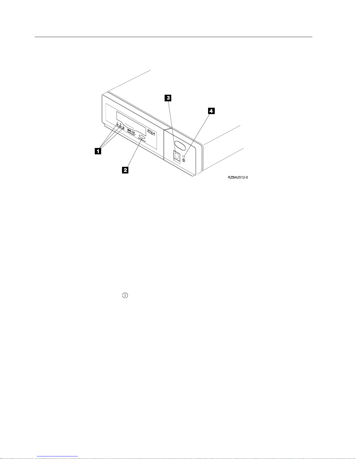
Figure 1 shows the front view of the 7206 Tape Drive.
Figure 1. Front View of the 7206 Model 220 4mm Tape Drive
1 Status lights 3 Power switch
2 Unload button 4 Power on light
|
Operator Controls
The 7206 Model 220 4mm Tape Drive has the following operator controls.
Power Switch
|
|
|
|
The power switch (3 in Figure 1) is a push button switch that enables the power
to be turned on or off. Push and release the button to turn the power on, when it
is off, or off when it is on. When the 7206 Tape Drive is on, the power-on light 4
is on.
Note: The
Organization for Standardization (ISO) symbol for a push button switch.
symbol located beside the power switch is an International
Unload Button
The unload button 2 enables the tape cartridge to be ejected. The unload button
operates only when the 7206 Tape Drive power is on. To remove a cartridge, press
and hold the unload button for about one second.
2 7206 Model 220 Service Guide
Page 17

Emergency Eject Feature
Attention: This procedure may result in loss of data.
|
|
|
|
|
|
The 7206 Tape Drive includes an emergency eject and reset feature that releases the
tape cartridge and resets the drive. Use the feature if the cartridge does not move
properly or if the unload process fails.
To perform an emergency eject of the tape cartridge or a reset of the drive, press
and hold the unload button for at least 5 seconds. If a cartridge is in the drive, it
automatically ejects without rewinding.
Indicator Lights
The 7206 Tape Drive has the following indicator lights.
Power-On Light
When the 7206 Tape Drive is turned on, the power-on light (4 in Figure 1 on
page 2) comes on and stays on.
Status Lights
Three status lights (1 in Figure 1 on page 2) and their ISO symbols appear on the
7206 Tape Drive as follows:
Ready (green)
Activity (green)
Fault (amber)
The combinations of the lights and their definitions are shown in Table 1 on page 4.
Chapter 1. Reference Information 3
Page 18

Table 1. Definition of Status Light Combinations
Ready
Flashing Off Off The Power-On Self Test (POST) is running or
Off or On On Off or Flashing The tape drive requires cleaning. See
Off Off or On Off One of the conditions exists:
On Off or On Off or Flashing A data cartridge has been inserted.
On Off or On Flashing The tape is in motion, and the 7206 Tape
Off Flashing Off The 7206 Tape Drive detected an internal
Fault Activity
Definition
the test cartridge is running.
“Cleaning the Tape Drive” on page 10.
v If the Ready light is on, a tape cartridge is
in the drive. If the light is off, a cartridge
is not in the drive.
v If the Activity light flashes, a tape
cartridge is in the drive and tape
movement is occurring. If the light is off,
no tape movement is occurring.
v The power is off (Fault light is off).
v The POST completed successfully, but no
tape cartridge has been inserted.
v If the Fault light is on, cleaning is
required. See “Cleaning the Tape Drive”
on page 10.
v The 7206 Tape Drive is ready to receive
commands from the system (whether the
Fault light is on or off).
v If the Fault light is on, cleaning is
required. See “Cleaning the Tape Drive”
on page 10.
v If the Activity light flashes, a tape
cartridge is in the drive and tape
movement is occurring. If the light is off,
no tape movement is occurring.
Drive is running an operation or is cleaning.
fault that requires corrective action.
v Reset the error by turning the power off to
the 7206 Tape Drive, then turning it back
on, or by holding down the open/close
button for 8 seconds.
v If the Fault light still flashes after the reset,
contact your service representative.
4 7206 Model 220 Service Guide
Page 19

Notes:
1. The 7206 Tape Drive needs cleaning when the tape drive turns on the Fault
status light (solid amber). The light turns on when:
v The 7206 Tape Drive determines that its soft error rate (recovered errors)
exceeds a preset soft-error rate limit, or
|
|
|
v The 7206 Tape Drive has been used for 50 tape motion hours without
cleaning. Tape motion hours are defined as the time the tape drive is moving
tape.
When the Fault light turns on (solid amber), the 7206 Tape Drive causes AIX to
log an information error (TAPE_ERR6) in the AIX log, indicating that the tape
drive needs to be cleaned.
|
2. IBM only supports the use of IBM media.
3. The 7206 Tape Drive is designed to operate in normal office environments.
Dirty environments or other poor environments may damage the tape drive. It
is the responsibility of the customer to provide the proper operating
environment.
4. When the tape drive indicates that the drive needs to be cleaned, it is the
responsibility of the customer to clean the tape drive with the recommended
cleaning cartridge.
5. If a DDS2 diagnostic cartridge (P/N 8191146) is used in the 7206 Tape Drive,
that cartridge will do automatic diagnostics.
6. If a DDS1 diagnostic cartridge (P/N 21F8762) is used, that cartridge will be
immediately ejected as an incorrect cartridge type.
Chapter 1. Reference Information 5
Page 20
Rear View
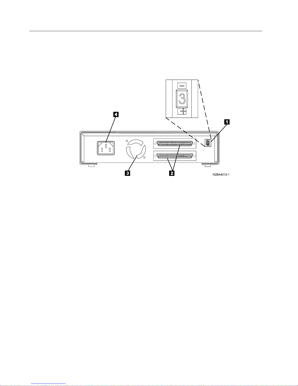
Figure 2 shows the elements on the rear of the 7206 Model 220 Tape Drive.
1 SCSI address switch 3 Cooling fan
2 SCSI bus cable connectors 4 Power cable connector
Figure 2. Rear View of the 7206 Model 220 Tape Drive
6 7206 Model 220 Service Guide
Page 21
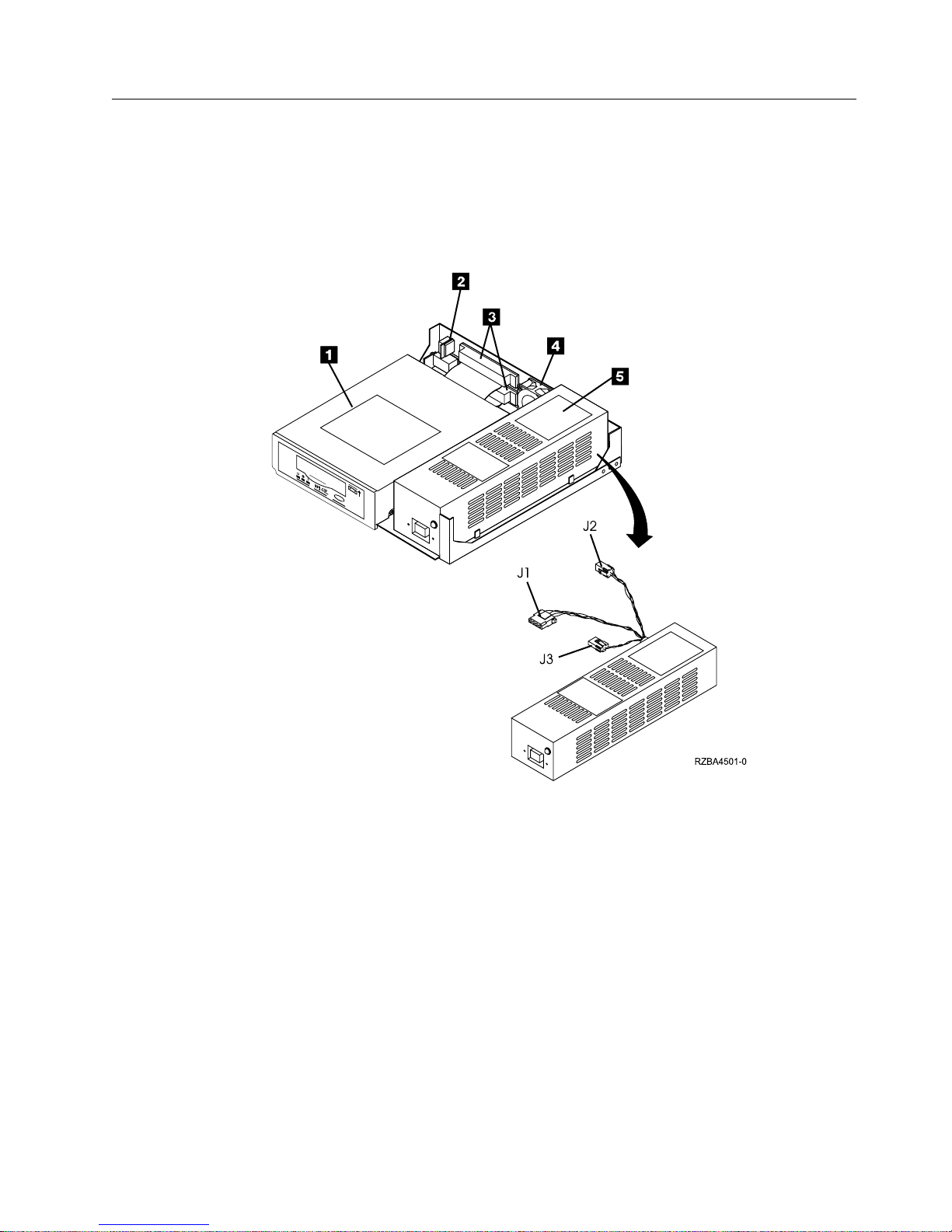
Internal View
Figure 3 shows the inside of the 7206 Model 220 Tape Drive.
1 Drive 4 Cooling fan
2 SCSI address switch 5 Power supply
3 SCSI bus cable
Figure 3. Internal View of the 7206 Model 220 Tape Drive
Chapter 1. Reference Information 7
Page 22

Rear View of the Drive
Figure 4 shows the connector locations on the drive.
1 SCSI address connector 3 Power supply connector
2 SCSI bus connector
Figure 4. Connector Locations on the Drive
8 7206 Model 220 Service Guide
Page 23

System Requirement
|
|
|
|
|
|
|
|
|
|
Specifications
The 7206 Tape Drive attaches to selected RS/6000 systems that uses a Wide Fast-20
LVD SCSI or single-ended FW SCSI adapter interface which meets the Small
Computer System Interface-2 (SCSI-2) standard X3.131-1994 Rev 10L of the
American National Standards Institute (ANSI).
The 7206 Tape Drive must be attached to a supported RS/6000 processor and
adapter with an AIX operating system at level:
v 4.1.5 (when installed with authorized program analysis report (APAR) #IX69941)
v 4.2 (when installed with APAR #IX69950) or higher
v 4.3 or higher
Table 2. Specifications for the 7206 Model 220 4mm Tape Drive
Physical Specifications
Width 250 mm (9.8 in.)
Depth 275 mm (10.8 in.)
Height 55 mm (2.2 in.)
Weight 3.7 kg (8 lb)
Power Specifications
kVA (typical) .03 @120 V ac
V ac Input 100 to 125
200 to 240
V dc Output +5 and +12
Frequency 50 to 60 Hz
Heat Output 77 Btu/hr (23 watts) @ 240 V ac
Power Factor .4 to .6
Other Specifications
Altitude 2135 m (7000 ft)
Recommended Environment
Environmental Factor Operating Non-operating
Temperature
16 to 32°C
(60 to 90°F)
Relative Humidity
20 to 80% 20 to 90%
(noncondensing)
23°C
Maximum Wet Bulb
(73°F)
10 to 43°C
(50 to 110°F)
27°C
(80°F)
Chapter 1. Reference Information 9
Page 24

Cleaning the Tape Drive
Clean the 7206 Tape Drive whenever the Fault status light comes on or a system
I/O error related to that device occurs.
|
|
|
|
|
|
|
|
|
|
|
|
|
|
Attention: Use only the recommended cleaning cartridge to clean the tape drive.
Use of other than recommended cleaning cartridges can damage your drive and
may void the warranty.
To clean the 7206 Tape Drive tape drive:
1. Make sure that the power is on to the 7206 Tape Drive. (The power-on light
should be on.)
2. If a tape cartridge is in the 7206 Tape Drive, eject and remove the cartridge.
Note: The IBM cleaning cartridge has 50 white dots on the window side that
are designed to be used to log the use of the cartridge. Each time the
cartridge is used, mark one of the dots on the cartridge with a pen or
marker. When all of the dots have been marked, discard the cleaning
cartridge.
3. Grasp the cleaning cartridge (1 in Figure 5) by the outer edges, with the
window side up and the write-protect switch 2 facing you.
4. Lift the door on the front of the 7206 Tape Drive and slide the cartridge into
the opening on the front of the 7206 Tape Drive until the loading mechanism
pulls the cartridge into the drive and the drive door closes.
Figure 5. Loading the Cleaning Cartridge
|
10 7206 Model 220 Service Guide
Page 25

After the cleaning cartridge has been inserted, the remainder of the cleaning
process is automatic. The 7206 Tape Drive:
1. Loads the cleaning cartridge into the tape drive
2. Cleans the drive by moving the cleaning tape forward for approximately 30
seconds
3. Unloads the cleaning cartridge when the cleaning operation is complete
4. Indicates a successful cleaning operation by turning off the Fault status light (if
the Fault light was on prior to the cleaning process; otherwise, the Fault light
remains solid to indicate that the cleaning cartridge is no longer usable)
If a system error occurs, clean the drive and retry the operation. If the operation
fails, replace the data cartridge, clean the drive again, then retry the operation.
To determine how many times a cleaning cartridge may be used, check the
information printed on the cartridge. If you attempt to use a depleted cleaning
cartridge, the 7206 Tape Drive automatically detects the error and ejects the
cartridge. If the Fault status light was on prior to the cleaning process, it stays on;
if the Fault light was off, the depleted cartridge causes the light to come on.
Chapter 1. Reference Information 11
Page 26

12 7206 Model 220 Service Guide
Page 27

Chapter 2. Using the Media
The 7206 Tape Drive uses 4mm data cartridges for saving and restoring system
data. It is designed to use only DDS (Digital Data Storage) data cartridges. The
cartridges are identified by one of the following DDS symbols:
|
|
|
|
|
|
|
The 7206 Tape Drive only reads and writes data to tape cartridges that are DDS-2,
3, or 4 format.
Note: The 7206 Model 220 Tape Drive only supports DDS-2, 3, and 4 tape
cartridges.
The 7206 Tape Drive has been designed to operate with DDS media that meet the
following standards of the European Computer Manufacturers Association
(ECMA):
v ECMA-198 DDS-2 format
v ECMA-236 DDS-3 format
v ECMA-288 DDS-4 format
Note: IBM only supports the use of IBM media.
Types of Tape Cartridges
The 7206 Tape Drive is shipped with the following media cartridges.
Data Cartridge Use the 4mm data cartridge to save or restore
Test Cartridge Use the specially labeled 4mm test cartridge to run
programs or data.
®
the AIX
running diagnostics, refer to your AIX manuals).
The test cartridge should not be used to save or
restore customer programs or data.
system diagnostics (for information about
Cleaning Cartridge Attention: Use of other than the IBM 4mm
To order additional cartridges, refer to “Appendix B. Ordering Tape Cartridges” on
page 45.
© Copyright IBM Corp. 2000 13
cleaning cartridge can damage your 7206 Tape
Drive and may void your warranty.
Use the specially labeled cleaning cartridge (part
number 21F8763) to clean the 7206 Tape Drive. For
instructions about how to clean the 7206 Tape
Drive, see “Cleaning the Tape Drive” on page 10).
Page 28

Recommendations for Data Cartridge Usage
The following list describes recommended guidelines that will help to protect your
data and prolong the life of your tape cartridges and the 7206 Tape Drive:
|
|
|
v Use only IBM 4mm DDS cartridges.
v Remove the tape cartridge from the drive when the drive is not in use.
v Back up and then discard any tape cartridge that repeatedly produces error
messages (the error information is in the System Error Log).
v On the data cartridge, do not open the door that covers the tape. The door
protects the tape from dirt, dust, and damage.
v Do not touch the tape. Any substance transferred to the tape by touching could
cause loss of data.
v Use only one label on a tape cartridge. Multiple or poorly placed labels can clog
the drive load mechanism.
v Do not use poor-quality tape cartridges. They can cause excessive read or write
errors, and may damage the tape drive.
v Discard any tape cartridges that are dropped, as the impact may damage the
tape’s internal mechanism.
v Make sure the environment is kept clean and constant. Do not operate in a
dusty environment and always maintain a constant environmental atmosphere.
A consistent storage and operating environment reduces media exposure to
climatic stress.
Attention: Use only the recommended cleaning cartridge to clean the tape drive.
Use of other than recommended cleaning cartridges can damage your drive and
may void the warranty.
v Printers and copiers can produce paper and toner dust. Locate the tape unit
away from these items. High traffic areas near hallways and doors can also
produce excess dust and dirt.
v All important information should be recorded on the tape label. Information,
such as the model and number of the system or tape drive, the date, the density,
any error statistics, and a log number should be included. The operating
environment and compression mode should also be noted.
Data Cartridge Erasure
|
|
|
Most bulk eraser devices do not have the capability to erase the 4mm data
cartridge. To properly erase a 4mm data cartridge with a bulk eraser device, the
erasure coercivity rating must be a minimum of 3900 Oersted.
Storage and Shipping Environments
Before using a tape cartridge, let it acclimate to the operating environment by
placing the cartridge in the operating environment for as long as it has been away
from the environment or for 24 hours, whichever is less. (To determine the
appropriate operating environment, see “Specifications” on page 9.)
Acclimation is necessary for any data cartridge exposed to a different humidity
environment or to temperature changes of 11°C (20°F) or more.
14 7206 Model 220 Service Guide
Page 29

Retrieval of archived data should be performed on a tape unit that is clean and
fully operational. Try to make the recovery environment the same as the operating
environment. Allow tapes at least 24 hours to acclimate to environment of the tape
unit.
The recommended environment for storage and shipment of 4mm data cartridges
is shown in Table 3.
Table 3. Recommended Environment for 4mm Data Cartridges
Environmental Factor Storage Shipping
Temperature
Relative Humidity
(noncondensing)
Maximum Wet Bulb
Tape Cartridge Storage
Tape drives record data using densities similar to hard disk drives. Because most
computer systems are not located in a dust-free, climate-controlled environment,
you must exercise special care when dealing with tape cartridges and tape drives.
They need to be treated as a valuable asset used to protect your business data.
5°Cto32°C
(41° to 90°F)
20 to 60% 5 to 80%
26°C
(79°F)
−40 to 52°C
(−40 to 125°F)
26°C
(79°F)
Use the following guidelines for storing your tape cartridges:
v Temperature and humidity should be kept constant at a level comfortable for
you.
v Tape cartridges should always be stored in their protective cases. The storage
case helps prevent damage from dust and physical misuse. When the tape
cartridges are not in use or being stored, they should be in their storage cases
and stood on edge in a designated storage location. Do not stack cartridges on
the flat side or stack other items on top of the tape cartridges. Handle your tape
cartridges with care to reduce archival problems.
v Stored tapes should be exercised at least once every 12 months. Run the tape
from Beginning of Data (BOD) to End of Data (EOD) and back to BOD at
normal operating speeds. Tapes stored in a warmer environment should be
exercised more frequently.
v Sunlight can damage the tape and the cartridge shell. Store tape cartridges out
of the direct sunlight
Attention: Operation outside of the environment can result in possible loss of
data or failure of the autoloader.
Chapter 2. Media 15
Page 30

Operating in Harsh Environments
Do not use as an archival tape any tape that has been used outside of the
operating ranges specified in Table 2 on page 9 for an extended period of time. The
magnetic and physical strength of the tape will have deteriorated as a result of its
exposure to the environment. Do not store important data on such a tape; transfer
the data to a newer tape for reliable archiving.
Attention: Do not operate the 7206 Tape Drive in a poor air-quality environment.
If your environment contains an excessive amount of particulates, contact your
service representative for more information.
Setting the Write-Protect Switch
The position of the write-protect switch on the 4mm tape cartridge determines
when you can write to the tape (see Figure 6).
v When the switch is set to the right 1, data can be written to and read from the
tape.
v When the switch is set to the left 2, data can only be read.
Figure 6. Setting the Write-Protect Switch
16 7206 Model 220 Service Guide
Page 31

Chapter 3. Maintenance Analysis Procedures
Purpose of the MAPs
Maintenance analysis procedures (MAPs) are used to check the:
Power cable SCSI address Drive
Power supply SCSI bus (signal) cable Fan
Terminator Configuration Drive head
If a problem is detected, the procedure isolates the problem to the failing field
replaceable unit (FRU), such as the 7206 Tape Drive drive, power supply, or
cooling fan. For instructions about removing or replacing a FRU, refer to
“Chapter 4. Removal and Replacement Procedures” on page 27.
Figure 7 on page 18 provides a flowchart to be used as a guide to the MAPs. For
detailed instructions on how to perform each procedure safely and correctly, refer
to the steps in this chapter.
© Copyright IBM Corp. 2000 17
Page 32

Flowchart of the MAPs
Figure 7. Flowchart of Maintenance Analysis Procedures (MAPs)
18 7206 Model 220 Service Guide
Page 33

Step 1: Power and Fan
This step verifies whether the power and the fan operate properly.
DANGER
An electrical outlet that is not correctly wired could place hazardous voltage
on metal parts of the system or the products that attach to the system. It is the
customer’s responsibility to ensure that the outlet is correctly wired and
grounded to prevent an electrical shock. (RSFTD201)
1. Make sure that the 7206 Tape Drive power cable is plugged into an electrical
outlet.
2. Make sure that the 7206 Tape Drive power is on by checking that:
v The power-on light is on.
v There is airflow from the fan at the rear of the unit.
Is the power-on light on and is there airflow from the fan?
NO While watching for the power-on light to come on, press the power switch
again. Repeat this procedure several times. If the power-on light fails to
come on or there is no airflow from the fan, go to Step 2: Electrical Outlet
Voltage.
YES Go to Step 7: SCSI Address Switch.
Step 2: Electrical Outlet Voltage
This step tests the voltage at the electrical outlet.
1. Do a controlled system shutdown (refer to the instructions in Chapter 2,
“Setting Up the 7206 Tape Drive,” in the 7206 Model 220 4mm Tape Drive Setup
and Operator Guide).
2. Ensure that the power to the system unit is off.
3. Press the 7206 Tape Drive power switch to turn off the power.
4. Unplug the 7206 Tape Drive power cable from the electrical outlet and from the
7206 Tape Drive.
DANGER
Dangerous voltage being measured. (RSFTD005)
5. Check the electrical outlets for proper voltage.
Is the voltage from the electrical outlet correct?
NO Contact your service personnel for further instructions.
YES Go to Step 3: Power Cable.
Chapter 3. Maintenance Analysis Procedures 19
Page 34

Step 3: Power Cable
This step determines whether the power cable is functional.
Make sure that all of the conductors in the power cable have continuity, and that
there are no short circuits.
Does the power cable have continuity and are there no short circuits?
NO Replace the power cable.
YES Go to Step 4: Power Supply, Fan, and Tape Drive.
Step 4: Power Supply, Fan, and Tape Drive
This step prepares the 7206 Tape Drive to determine whether the power supply,
fan, or tape drive is the cause of the problem.
1. Perform the cover removal procedure. Refer to “Removing and Replacing the
Cover” on page 28.
2. Plug the 7206 Tape Drive power cable into the 7206 Tape Drive and into the
electrical outlet.
3. Press the power switch to turn off the power.
DANGER
Up to 240 V ac is present at the power module connectors when the main
power cord is connected to a power source. (RSFTD010)
|
|
4. Disconnect the power supply connector (J1) from the drive (refer to Figure 3 on
page 7).
5. Disconnect the power supply connector (J2) between the power supply and the
cooling fan.
6. Press the power switch to turn on the power.
Does the power-on light come on and stay on?
NO Replace the power supply. Refer to “Removing and Replacing the Power
Supply” on page 32.
DANGER
Do not attempt to open the covers of the power supply. Power supplies are
not serviceable and are to be replaced as a unit. (RSFTD217)
YES Go to Step 5: Cooling Fan.
20 7206 Model 220 Service Guide
Page 35

Step 5: Cooling Fan
This step examines the cooling fan as the possible source of the problem.
1. Press the power switch to turn off the power.
DANGER
Up to 240 V ac is present at the power module connectors when the main
power cord is connected to a power source. (RSFTD010)
|
|
|
|
|
Step 6: Tape Drive
|
|
2. Reconnect the power supply connector (J2) to the cooling fan (refer to Figure 3
on page 7).
3. Press the power switch to turn on the power.
Does the power-on light come on and stay on, and is there airflow from the fan?
NO Power off the 7206 Tape Drive and then replace the cooling fan. Verify that
the power-on light comes on when power is restored to the device. Refer
to “Removing and Replacing the Cooling Fan” on page 34.
YES Go to Step 6: Tape Drive.
This step examines the drive as the possible source of the problem.
1. Press the power switch to turn off the power.
DANGER
Up to 240 V ac is present at the power module connectors when the main
power cord is connected to a power source. (RSFTD010)
2. Reconnect the power supply connector (J1) to the drive (refer to Figure 3 on
page 7).
3. Press the power switch to turn on the power.
Does the power-on light come on and stay on, and is there airflow from the fan?
|
|
|
|
|
NO Power off the 7206 Tape Drive and then replace the drive. Refer to
“Removing and Replacing the Drive” on page 30.
Note: If the media is still in the drive being replaced, it can be removed
manually. See “Manually Removing a Tape Cartridge” on page 35.
YES Go to Step 9: Tape Drive Status Lights.
Chapter 3. Maintenance Analysis Procedures 21
Page 36

Step 7: SCSI Address Switch
This step checks that the SCSI address switch setting is correct.
Is the SCSI address set correctly?
NO Set the SCSI address switch to the proper address, then go to Step 12:
External SCSI Cable Connection. To set the SCSI address switch, refer to
the instructions in Chapter 2, “Setting Up the 7206 Tape Drive,” in the 7206
|
Model 220 4mm Tape Drive Setup and Operator Guide.
|
|
|
YES Go to Step 8: SCSI Address Cable.
Note: You should turn the power to the 7206 Tape Drive off and then back
Step 8: SCSI Address Cable
This step checks whether the SCSI address switch is plugged into the drive.
1. Do a controlled system shutdown (refer to the instructions in Chapter 2,
“Setting Up the 7206 Tape Drive,” in the 7206 Model 220 4mm Tape Drive Setup
and Operator Guide).
2. Perform the cover removal procedure. Refer to “Removing and Replacing the
Cover” on page 28.
DANGER
To prevent a possible electrical shock from touching two surfaces with
different electrical grounds, use one hand, when possible, to connect or
disconnect signal cables. (RSFTD004)
Is the SCSI address switch plugged securely into the drive?
NO Ensure that the SCSI address switch is plugged securely into the drive,
then go to Step 11: Reassembly.
YES Go to Step 9: Tape Drive Status Lights.
on again to ensure the SCSI address setting is recognized.
Step 9: Tape Drive Status Lights
This step examines the drive as the possible source of the problem.
While pressing the power switch to turn on the power, watch to see if the three
status lights come on for approximately 10 seconds, then go out.
Did the three status lights come on for approximately 10 seconds, then go out?
NO Go to Step 10: Power Supply Voltage Level.
YES Go to Step 11: Reassembly.
22 7206 Model 220 Service Guide
Page 37

Step 10: Power Supply Voltage Level
This step checks the power supply voltage levels as the possible source of the
problem.
1. Press the power switch to turn off the power.
2. Perform the cover removal procedure. Refer to “Removing and Replacing the
Cover” on page 28.
3. Disconnect the power supply connector (J1) from the drive.
4. Disconnect the power supply connector (J2) between the power supply and the
cooling fan.
5. Connect the power cable to both the 7206 Tape Drive and the electrical outlet.
6. Press the power switch to turn on the power.
DANGER
Dangerous voltage being measured. (RSFTD005)
7. On the power supply connector J1 (see Figure 8), check the following:
v The +12V signal falls between a minimum of +11.5 volts and a maximum of
+12.6 volts
v The +5V signal falls between a minimum of +4.8 volts and a maximum of
+5.25 volts
Figure 8. Power Supply Connector J1
8. On the power supply connector J2 (see Figure 9), check that the +12V signal
falls between a minimum of +11.5 volts and a maximum of +12.6 volts.
Figure 9. Power Supply Connector J2
Are the voltages good?
NO Replace the power supply. Refer to “Removing and Replacing the Power
Supply” on page 32.
YES Replace the drive. See “Removing and Replacing the Drive” on page 30.
Note: If the media is still in the drive being replaced, it can be removed
manually. See “Manually Removing a Tape Cartridge” on page 35.
Chapter 3. Maintenance Analysis Procedures 23
Page 38

Step 11: Reassembly
This step describes the reassembly process.
1. Press the power switch to turn off the power.
2. Unplug the power cable from the electrical outlet.
3. Make sure that the power supply connector (J1) is plugged into the drive.
4. Make sure that the power supply connector (J2) is plugged into the cooling fan.
5. Make sure that all other cables are properly connected, and that the wires are
routed away from the cooling fan.
6. Perform the cover replacement procedure. Refer to “Removing and Replacing
the Cover” on page 28.
7. Plug the power cable into the electrical outlet.
8. Press the power switch to turn on the power.
Does the power-on light come and stay on, and is there airflow from the fan?
NO Verify that the 7206 Tape Drive was reassembled correctly. If the power-on
light still does not come on and there is no airflow from the fan, go to Step
1: Power and Fan.
YES Go to Step 12: External SCSI Cable Connection.
Step 12: External SCSI Cable Connection
This step ensures that the external SCSI bus cable connection is proper.
DANGER
To prevent a possible electrical shock when installing the device, ensure that
the power cord for that device is unplugged before installing signal cables.
(RSFTD204)
Ensure that the SCSI bus cable is properly connected to both the system unit and
to the 7206 Tape Drive.
Is the SCSI bus cable properly connected to the system unit and to the 7206
Tape Drive?
NO Plug the SCSI bus cable into the system unit and into the 7206 Tape Drive,
then go to Step 13: Terminator Connection.
YES Go to Step 13: Terminator Connection.
24 7206 Model 220 Service Guide
Page 39

Step 13: Terminator Connection
This step ensures that the terminator connection is proper.
DANGER
To prevent a possible electrical shock when installing the device, ensure that
the power cord for that device is unplugged before installing signal cables.
(RSFTD204)
Ensure that the terminator is properly connected to the last device on the SCSI bus.
Is the terminator properly connected to the last device on the SCSI bus?
NO Ensure that the terminator is properly connected to the last device on the
SCSI bus, then go to Step 14: Configuration.
YES Go to Step 14: Configuration.
Step 14: Configuration
This step verifies that the 7206 Tape Drive has been properly configured to the
RS/6000.
1. Clean the drive. See “Cleaning the Tape Drive” on page 10.
2. At the system prompt, type cfgmgr to configure the 7206 Tape Drive and make
it Available.
To ensure that 7206 Tape Drive has been correctly configured to the RS/6000, refer
to Chapter 2, “Setting Up the 7206 Tape Drive,” in the 7206 Model 220 4mm Tape
Drive Setup and Operator Guide.
Is the 7206 Tape Drive properly configured to the RS/6000?
NO Go to Step 15: AIX Diagnostics.
YES Go to Step 15: AIX Diagnostics.
Chapter 3. Maintenance Analysis Procedures 25
Page 40

Step 15: AIX Diagnostics
This step runs the AIX diagnostics to determine the problem.
|
|
|
|
|
|
|
|
|
Run the diagnostics on the 7206 Tape Drive. Have the test cartridge (part number
59H4457) available for when the diagnostics prompt you to load the cartridge.
From the AIX command prompt, type:
diag
and then press Enter. For additional instructions on running diagnostics, refer to
your AIX manuals.
Do all of the diagnostics routines pass?
NO Replace the FRU isolated by the diagnostics and identified by the service
request number.
Note: If the drive is the FRU isolated by the diagnostics, check that the J1
connector is properly seated. If the drive has recently been replaced
because of a similar problem, contact your service personnel.
YES If no problem was identified, the problem may be intermitant, related to
the tape quality, or relating to the environment. If a FRU was replaced or
changed and no more errors occur, the problem is fixed.
This completes the MAPs.
26 7206 Model 220 Service Guide
Page 41

Chapter 4. Removal and Replacement Procedures
This chapter describes the procedures to follow when removing and replacing the
field replaceable units (FRUs), such as the drive, power supply, and cooling fan for
the 7206 Model 220 Tape Drive. It also describes how to manually remove a tape
cartridge from the 7206 Tape Drive.
Before installing any FRU, let it acclimate to the operating environment for as long
as it has been away from the environment or for 24 hours, whichever is less.
Handling Static-Sensitive Devices
Attention: Tape drives are sensitive to static electricity discharge. To prevent
damage, when handling a tape drive wrap it in an antistatic bag.
Take the following precautions:
v Do not remove the drive from its antistatic bag until you are ready to install it.
v With the drive still in its antistatic bag, touch it to the metal frame of an
electrically grounded surface.
v Hold the drive by the frame. Avoid touching the solder joints or pins.
v Handle the drive carefully to prevent permanent damage.
© Copyright IBM Corp. 2000 27
Page 42

Removing and Replacing the Cover
To remove the cover from the 7206 Tape Drive:
1. If a tape cartridge is in the drive, eject it.
2. Do a controlled system shutdown (refer to the instructions in Chapter 2,
“Setting Up the 7206 Tape Drive,” in the 7206 Model 220 4mm Tape Drive Setup
and Operator Guide).
3. If it is on, turn off the power to the 7206 Tape Drive.
DANGER
To prevent a possible electrical shock when installing the device, ensure that
the power cord for that device is unplugged before installing signal cables.
(RSFTD204)
4. Unplug the 7206 Tape Drive power cable from the electrical outlet.
5. Disconnect the power cable from the 7206 Tape Drive.
6. Disconnect the SCSI bus cable from the 7206 Tape Drive.
7. Tilt the 7206 Tape Drive on its side and remove the four cover mounting screws
from the bottom. See Figure 10 on page 29.
8. Remove the cover by sliding it to the rear (see the directional arrow in
Figure 10 on page 29).
28 7206 Model 220 Service Guide
Page 43

To replace the cover, reverse the removal procedure.
Figure 10. Removing and Replacing the Cover. The 7206 Tape Drive is shown tilted on its
side.
Chapter 4. Removal and Replacement 29
Page 44

Removing and Replacing the Drive
To remove the drive from the 7206 Tape Drive:
1. Perform the cover removal procedure. Refer to “Removing and Replacing the
Cover” on page 28.
2. Disconnect the power supply connector (J1) (1 in Figure 11) from the drive.
3. Disconnect the SCSI bus cable 2 from the drive.
4. Disconnect the SCSI address cable 3 from the drive.
5. Tilt the 7206 Tape Drive on its side (see Figure 11). Support the drive 4 while
removing the four screws 5 that secure the drive to the chassis.
6. Support the drive while returning the 7206 Tape Drive to its original position.
7. Slide the drive out the front of the chassis.
Figure 11. Removing and Replacing the Drive
30 7206 Model 220 Service Guide
Page 45

To replace the drive, reverse the removal procedure. Make sure to
v Correctly insert and engage each cable to its proper connector.
v Arrange the cables so that they do not interfere with the cooling fan blades or
the replacement of the cover.
Note: The power supply connector J3 is not used in the 7206 Tape Drive.
Chapter 4. Removal and Replacement 31
Page 46

Removing and Replacing the Power Supply
DANGER
Do not attempt to open the covers of the power supply. Power supplies are
not serviceable and are to be replaced as a unit. (RSFTD217)
To remove the power supply from the 7206 Tape Drive:
1. Perform the cover removal procedure. Refer to “Removing and Replacing the
Cover” on page 28.
2. Tilt the 7206 Tape Drive on its side. Support the power supply (1 in
Figure 12) while removing the power supply mounting screw 2 from the
bottom.
3. Support the power supply while returning the 7206 Tape Drive to its original
position.
4. Disconnect the power supply connector (J1) (3 from the drive.
5. Disconnect the power supply connector (J2) 4 between the power supply and
the cooling fan.
6. Grasp the rear of the power supply and while pressing it toward the front
panel, lift the rear of the power supply from the chassis.
7. Push the power switch push button 5 out of the front panel and set it aside.
Figure 12. Removing and Replacing the Power Supply
32 7206 Model 220 Service Guide
Page 47

To replace the power supply, reverse the removal procedure. Make sure to:
v Align the power supply inside the two tabs (6 in Figure 12 on page 32) on the
base of the chassis.
v With its locking features in a horizontal position, insert the power switch push
button 5 into the front panel and press until it locks in place.
Note: If the power switch does not work properly, loosen the power supply
mounting screw, slide the power supply to the rear of the chassis, and
retighten the mounting screw.
v Arrange the cables so that they do not interfere with the cooling fan blades or
the replacement of the cover. Ensure that they do not obstruct airflow through
the fan.
|
|
|
Note: The power supply connector J3 is not used in the 7206 Tape Drive. Make
sure that the J3 connector is placed in a position so it will not interfere with
the operation of the drive or the fan.
|
Chapter 4. Removal and Replacement 33
Page 48

Removing and Replacing the Cooling Fan
To remove the cooling fan:
1. Perform the cover removal procedure. Refer to “Removing and Replacing the
Cover” on page 28.
2. Disconnect the power supply connector (J2) (1 in Figure 13) between the
power supply and the cooling fan.
3. Remove the two screws, lockwashers, and nuts 2 that secure the cooling fan
to the rear of the 7206 Tape Drive.
4. Lift the cooling fan out of the 7206 Tape Drive.
To replace the cooling fan, reverse the removal procedure. Make sure that the
cooling fan is oriented so that air blows out of the 7206 Tape Drive.
Figure 13. Removing and Replacing the Cooling Fan
34 7206 Model 220 Service Guide
Page 49

Manually Removing a Tape Cartridge
Attention: The procedure for manually removing a tape cartridge could damage
your tape cartridge, the 7206 Tape Drive, or both. Use this procedure only after
you have:
1. Turned the power to the 7206 Tape Drive off and on again to clear potential
hang conditions.
2. If available, issued the Unload SCSI command from your system command
menu.
3. Disconnected the 7206 Tape Drive from the system, and turned the power to
the 7206 Tape Drive on and off again several times.
|
|
|
4. Attempted an emergency eject of the cartridge by pressing and holding the
unload button for at least five seconds (see “Emergency Eject Feature” on
page 3).
|
|
The following procedure describes how to manually remove a data cartridge from
the 7206 Tape Drive. If this procedure is performed, replace the drive.
1. Remove the drive from the 7206 Tape Drive (see “Removing and Replacing the
Drive” on page 30).
2. Remove the mounting rails by removing the four screws (1 in Figure 14) near
the lower edge of the drive (two on each side). Access the screws through holes
in the side of each rail.
3. Remove the front bezel (the bezel snaps on) by doing the following:
a. Use a small screwdriver to depress one of the bezel tabs 2.
b. Pull the bezel down from the top.
c. Lift the bezel off the bottom locating tabs.
d. Remove the bezel from the unit.
Figure 14. Removing the Mounting Rails from the Drive
Chapter 4. Removal and Replacement 35
Page 50

4. Remove the top lid of the drive mechanism (4 screws).
5. Insert a 1.5 mm hexagonal key or a small Phillips screwdriver into the aperture
on the right side of the drive looking from rear. This gives you access to the
motor worm wheel, as shown in Figure 15. Turn the hexagonal key or small
screwdriver counter-clockwise to release the cartridge.
Note: This may take more than 1000 turns
Figure 15. Turning the Motor Worm Wheel to Release the Cartridge
6. Reassemble the drive in reverse order.
36 7206 Model 220 Service Guide
Page 51

Chapter 5. Parts Diagram and Parts List
How To Use This Parts List
AR (As Required) in the Units column indicates that the quantity is not
the same for all machines.
NP (Non-Procurable) in the Part Number column indicates that the part
is non-procurable and that the individual parts or the next higher
assembly should be ordered.
NR (Not Recommended) in the Units column indicates that the part is
procurable but not recommended for field replacement, and that
the next higher assembly should be ordered.
00 (Not Shown) in the Asm- Index column indicates that the part is
either not shown or not referenced in the illustration.
R (Restricted) in the Units column indicates that the part has a
restricted availability.
Indenture The indenture is marked by a series of dots located before the
parts description. The indenture indicates the relationship of a part
to the next higher assembly. For example:
Indenture Relationship of Parts
(No dot) MAIN ASSEMBLY
(One dot) v Detail parts of a main assembly
(One dot) v Sub assembly of the main assembly
(Two dots) vvDetail part of a one-dot sub assembly
(Two dots) vvSub assembly of a one-dot sub assembly
(Three dots) vvvDetail part of a two-dot sub assembly
Example of Parts Listing
AsmIndex
3- 2512667
-1 5373637 1 vSeal, Top
-2 5356429 2 vClip, Retaining
-3 1847630 1 vFinger Stock Asm
-4 1847602 NR vvChannel, Finger Stock
-5 5373639 AR vSeal, Bottom
-6 5356429 2 vClip, Retaining
-7 NP 1 vCover, Rear, Without Paint
-5 0416629 R vScrew, Panel
Part Number Units Description
2513714
1
1
Cover Asm, Rear, Red
Cover Asm, Rear, White
For Next Higher Asm, see Assembly 1-2.
© Copyright IBM Corp. 2000 37
Page 52

Assembly 1: Parts Diagram
38 7206 Model 220 Service Guide
Page 53

Assembly 1: (continued)
Asm–
Index
1–1 59H3760 1 Power supply
–2 46G2677 3 Screw, power supply, M3 x 6mm
–3 42F7300 1 Cooling fan
–4 46G2676 2 Screw, cooling fan
–5 1622401 2 Nut, cooling fan
–6 1622344 2 Washer, cooling fan, optional P/N 0338169
–7 59H2694 1 Cable, SCSI address
–8 59H2689 1 Chassis
–9 46G2677 2 Screw, cover, M3 x 6mm
–10 35L1162 1 Cable, 68–pin SCSI internal
–11 0251970 4 Screw, SCSI connectors
–12 46G2677 4 Screw, drive, M3 x 6mm
–13 34L3614 1 Tape drive, 4mm
–14 59H3847 1 Cover, includes feet
–15 74G8497 1 Push button, power supply
–00 52G4291 1 Device-to-device SCSI cable, .7 meter (2 ft) 68P to 68P
–00 06H6036 1 System-to-device SCSI cable, 1 meter (3 ft) 68P to 68P
–00 52G9501 1 System-to-device SCSI cable, 1.5 meter (5 ft) CC68 to 68P
–00 52G4337 1 System-to-device SCSI cable, 1.5 meter (5 ft)
–00 76H0518 1 Interposer, .3 meter (1 ft) VHDCI 68 to 68s
–00 52G9907 1 Terminator, SE 68 pin
–00 35L0145 1 Terminator, LVD/SE 68 pin
–00 59H4458 1 Data cartridge
–00 59H4457 1 Test cartridge
–00 21F8763 1 Cleaning cartridge
Part
Number Units Description
Chapter 5. Parts Diagram and List 39
Page 54

40 7206 Model 220 Service Guide
Page 55

Appendix A. Power Cables
To avoid electrical shock, a power cable with a grounded attachment plug has been
provided. Use only properly grounded outlets.
Power cables used in the United States and Canada are listed by Underwriter’s Laboratories
™
) and certified by the Canadian Standards Association (CSA™). The power cables
(UL
consist of:
v Electrical cables, type SVT or SJT.
v Attachment plugs complying with National Electrical Manufacturers Association (NEMA)
5-15P, that is:
“For 115 V operation use a UL Listed Cable Set consisting of a minimum 18 AWG, Type
SVT or SJT three conductor cable a maximum of 15 feet in length and a parallel blade,
grounding type attachment plug rated at 15 A, 125 V.”
“For 230 V operation in the United States use a UL Listed Cable Set consisting of a
minimum 18 AWG, Type SVT or SJT three conductor cable a maximum of 15 feet in
length, and a tandem blade, grounding type attachment plug rated at 15 A, 250 V.”
v Appliance couplers complying with International Electrotechnical Commission (IEC)
Standard 320, Sheet C13.
Power cables used in other countries consist of:
v Electrical cables, type HD21.
v Attachment plugs approved by the appropriate testing organization for the specific
countries where they are used.
“For units set at 230 V (outside of U. S.): Use a Cable Set consisting of a minimum 18
AWG cable and grounding type attachment plug rated 15 A, 250 V. The Cable Set should
have the appropriate safety approvals for the country in which the equipment is to be
installed and marked 'HAR'.”
Table 4 on page 42 lists the power cable part number, the country where the power cable can
be used, and an index number to be matched with the receptacles shown in Figure 16 on
page 43. If your power cable does not match this information, contact your local dealer.
© Copyright IBM Corp. 2000 41
Page 56

Table 4. Power Cable Information
Part Number Country Index
1838574 Japan Bahamas, Barbados, Bolivia, Brazil, Canada, Costa
Rica, Dominican Republic, Ecuador, El Salvador,
Guatemala, Guyana, Haiti, Honduras, Jamaica,
Japan, Netherlands Antilles, Panama, Peru,
Philippines, Taiwan, Thailand, Tobago, Trinidad,
U.S.A. (except Chicago), Venezuela
6952300 US/Canada Bahamas, Barbados, Bermuda, Bolivia, Brazil,
Canada, Cayman Islands, Colombia, Costa Rica,
Dominican Republic, Ecuador, El Salvador,
Guatemala, Guyana, Haiti, Honduras, Jamaica,
Japan, Korea (South), Mexico, Netherlands
Antilles, Nicaragua, Panama, Peru, Philippines,
Puerto Rico, Saudi Arabia, Suriname, Taiwan,
Trinidad, U.S.A. (except Chicago), Venezuela
6952301 6 ft Chicago Chicago, U.S.A. 2
13F9940 Australia Argentina, Australia, New Zealand, Uruguay 3
13F9979 France Abu Dhabi, Austria, Belgium, Bulgaria, Botswana,
Egypt, Finland, France, Germany, Greece, Iceland,
Indonesia, Korea (South), Lebanon, Luxembourg,
Macau, Netherlands, Norway, Portugal, Saudi
Arabia, Spain, Sudan, Sweden, Turkey, Yugoslavia
13F9997 Denmark Denmark 5
14F0015 South Africa Bangladesh, Burma, Pakistan, South Africa, Sri
Lanka
14F0033 United
Kingdom
14F0051 Switzerland Liechtenstein, Switzerland 8
14F0069 Italy Chile, Ethiopia, Italy 9
14F0087 Israel Israel 10
6952291 Colombia Colombia, Paraguay 11
Bahrain, Bermuda, Brunei, Channel Islands,
Cyprus, Ghana, Hong Kong, India, Iraq, Ireland,
Jordan, Kenya, Kuwait, Malawi, Malaysia,
Nigeria, Oman, People’s Republic of China, Qatar,
Sierra Leone, Singapore, Tanzania, Uganda,
United Arab Emirates (Dubai), United Kingdom,
Zambia
1
2
4
6
7
42 7206 Model 220 Service Guide
Page 57

123
56 7 8
910 11
4
Figure 16. Types of Receptacles
Appendix A. Power Cables 43
Page 58

44 7206 Model 220 Service Guide
Page 59

Appendix B. Ordering Tape Cartridges
All tape cartridges are not alike. The tape composition and length, and the
construction of the cartridge itself can all affect the quality and capacity of the
recording and the performance of your tape drive. A poor quality tape cartridge
may appear to work adequately in your system, yet it can leave contamination in
the tape path or impede the speed of the recording.
The length and composition of the tape, and the size, shape, and construction of
the cartridge shell must all be considered when selecting the tape cartridge to be
used with your system. We recommend using only data and cleaning cartridges
supplied by IBM. Data grade tape media is the only type of tape media that
should be used for backup and data processing. Saving money by using generic
media for data purposes will do little to save your business if your data is
destroyed and your backup tapes fail because of inferior media.
Table 5 lists the tape cartridges that you can order for the 7206 Model 220 4mm
Tape Drive. To order cartridges in the United States and Canada, call
1-888-IBM-MEDIA. To order cartridges in other locations, contact your local
|
provider of IBM storage products.
|
|
|||
|||
|
|||
Table 5. Tape Cartridges for the 7206 Model 220 4mm Tape Drive
IBM Part Number Type of Cartridge Length
59H4458
4mm Data Cartridge
21F8763 4mm Cleaning Cartridge --
150 m
(492 ft)
|
© Copyright IBM Corp. 2000 45
Page 60

46 7206 Model 220 Service Guide
Page 61

|
Appendix C. Safety Inspection Procedures
Use the following procedures to identify unsafe conditions. Be cautious of potential
safety hazards not covered by the procedures. If unsafe conditions are present,
determine how serious the hazards are and whether you should continue before
correcting the problem.
Figure 17 shows the components to review during the service inspection.
Figure 17. Safety Inspection
Perform the following safety checks.
1. Do a controlled system shutdown (refer to the instructions in Chapter 2,
“Setting Up the 7206 Tape Drive,” in the 7206 Model 220 4mm Tape Drive Setup
and Operator Guide).
2. Turn off the power to all external devices connected to the system unit.
3. Turn off the power to the 7206 Tape Drive (1 in Figure 17).
4. Turn off the power to the system unit 2.
© Copyright IBM Corp. 2000 47
Page 62

DANGER
An electrical outlet that is not correctly wired could place hazardous voltage
on metal parts of the system or the products that attach to the system. It is the
customer’s responsibility to ensure that the outlet is correctly wired and
grounded to prevent an electrical shock. (RSFTD201)
5. Unplug the 7206 Tape Drive external power cable from the electrical outlet.
6. Unplug the system unit power cable from the electrical outlet.
7. Check the 7206 Tape Drive external power cable for damage.
DANGER
To prevent a possible electrical shock when adding or removing any devices
to or from the system, ensure that the power cords for those devices are
unplugged before the signal cables are connected or disconnected. If possible,
disconnect all power cords from the existing system before you add or
remove a device. (RSFTD203)
DANGER
To prevent a possible electrical shock from touching two surfaces with
different electrical grounds, use one hand, when possible, to connect or
disconnect signal cables. (RSFTD004)
8. Check the external SCSI bus (signal) cable 3 for damage.
9. Check the SCSI bus terminator for damage.
10. Check the covers for sharp edges, damage, or alterations that expose the
internal parts of the 7206 Tape Drive.
11. Check the covers for proper fit. They should be in place and secure.
12. Check the product label on the bottom of the 7206 Tape Drive to make sure it
matches the voltage at your outlet.
DANGER
Dangerous voltage being measured. (RSFTD005)
13. Check the voltage level at the outlet and also check for proper grounding (see
Figure 18 on page 49).
48 7206 Model 220 Service Guide
Page 63

Figure 18. AC Grounding Diagram (50 Hz and 60 Hz)
14. With the external power cable (1 in Figure 19) connected to the 7206 Tape
Drive, check to ensure 1.0 ohm or less resistance between the ground lug on
the external power cable plug and the metal frame.
Figure 19. Safety Inspection - Rear View of the 7206 Model 220 4mm Tape Drive
Note: Use an analog meter to measure grounding resistance; do not use a
digital multimeter.
Appendix C. Safety Inspection Procedures 49
Page 64

15. If the 7206 Tape Drive passes the test in the previous steps, plug its external
power cable into the electrical outlet. If the 7206 Tape Drive does not pass the
test, see “Chapter 3. Maintenance Analysis Procedures” on page 17 for more
information. If problems persist, contact your service representative.
Note: Safety Information Label, Part Number 85F7884, located on top of the power
supply under the top cover, shows the following symbol:
38M0010
This symbol indicates a hazard arising from dangerous voltage inside. Do not
open.
50 7206 Model 220 Service Guide
Page 65

Readers’ Comments — We’d Like to Hear from You
7206 Model 220 External 4mm Tape Drive
7206 Model 220
4mm Tape Drive
Service Guide
Publication No. SY32-0409-01
Overall, how satisfied are you with the information in this book?
Very Satisfied Satisfied Neutral Dissatisfied Very
Dissatisfied
Overall satisfaction hhhhh
How satisfied are you that the information in this book is:
Very Satisfied Satisfied Neutral Dissatisfied Very
Dissatisfied
Accurate hhhhh
Complete hhhhh
Easy to find hhhhh
Easy to understand hhhhh
Well organized hhhhh
Applicable to your tasks hhhhh
Please tell us how we can improve this book:
Thank you for your responses. May we contact you? h Yes h No
When you send comments to IBM, you grant IBM a nonexclusive right to use or distribute your comments in any
way it believes appropriate without incurring any obligation to you.
Name Address
Company or Organization
Phone No.
Page 66

___________________________________________________________________________________________________
Readers’ Comments — We’d Like to Hear from You
SY32-0409-01
_________________________________________________________________________________________
Fold and Tape Please do not staple Fold and Tape
NO POSTAGE
NECESSARY
IF MAILED IN THE
UNITED STATES
Cut or Fold
Along Line
BUSINESS REPLY MAIL
FIRST-CLASS MAIL PERMIT NO. 40 ARMONK, NEW YORK
POSTAGE WILL BE PAID BY ADDRESSEE
International Business Machines Corporation
Information Development
Department 542
3605 Hwy 52 North
Rochester, Minnesota 55901-7829
_________________________________________________________________________________________
Fold and Tape Please do not staple Fold and Tape
SY32-0409-01
Cut or Fold
Along Line
Page 67

Page 68

Part Number: 35L0857
Printed in U.S.A.
SY32-0409-01
35L0857
 Loading...